drs61: incremental encoders, number of lines and zero ... · pdf filelines and zero pulse...
TRANSCRIPT

C
DRS61: Incremental encoders, number oflines and zero pulse width freely programmable
DRS60: Incremental Encoderswith Zero-Pulse-Teach
DA
TA
SH
EE
T
CoreTech technology permits
tailor-made solutions for every
application, due to its modular
design.
With DRS61 incremental enco-
ders, the number of lines from 1
to 8,192 and the width of the
zero pulse can be freely program-
med by the customer. Therefore,
they will be of particular interest
to end users, distributors, consul-
ting engineers and system inte-
grators.
DRS60 incremental encoders are
available with any desired number
of lines between 1 and 8,192.
Further highlights of this generation
of encoders:
· Simple zero-pulse-teach by
pressing a button located under
a cap on the rear of the encoder
· Excellent price/performance
ratio
· Long LED lifetime as a result of
automatic light regulation
· Maximum reliability as a result of
opto-ASICs with Chip-on-Board
technology
· Interchangeable collets for hollow
shaft diameters from 6 to 15 mm
and 1/4, 3/8, 1/2 inch.
Whether with face mount flange,
servo flange, blind or through hollow
shaft with connector or cable outlet,
TTL or HTL interface – DRS60/61
encoders will meet virtually any ap-
plication profile.
Thanks to this wide variety of
products, there are numerous
possible uses, for example in:
· machine tools
· textile machines
· woodworking machines
· packaging machines
Number of lines1 up to 8,192
Incremental Encoder
NEW
01-2006

PIN Signal Wire colour Explanation
(Cable outlet)
1 B black Signal line
2 Sense + grey Connected internally to Us
3 Z lilac Signal line
4 Z yellow Signal line
5 A white Signal line
6 A brown Signal line
7 N. C. orange Not connected
8 B pink Signal line
9 Screen Housing potential
10 GND blue Zero volt connected to the encoder
11 Sense – green Connectedinternally to GND
12 Us red Supply voltage 1)
1) Potential free tohousing
N. C. = Not connected
2 SICK-STEGMANN
Incremental Encoder DRS60/DRS61, face mount flange
Connector or cable outletProtection class up to IP 66Electrical interfaces TTL and HTLZero-Pulse-Teach viapressing a buttonDRS61: number of lines andzero pulse width can be freelyprogrammed by the customer
Dimensional drawing face mount flange radial
Dimensional drawing face mount flange axial
PIN and wire allocation/cable 11 core
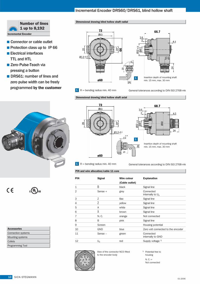
View of the connector M23 fitted to the encoder body
1
1
R = bending radius min. 40 mm1
R = bending radius min. 40 mm1
General tolerances according to DIN ISO 2768-mk
General tolerances according to DIN ISO 2768-mk
Accessories
Connection systems
Mounting systems
Programming Tool
Number of lines1 up to 8,192
Incremental Encoder
01-2006

Solid shaft 10 mm
Number of lines per revolution 00001 up to 08192, see order info
Electrical Interface TTL/RS 422, 6-channel
HTL/push-pull, 6-channel
Mass 1) Approx. 0.3 kg
Moment of inertia of the rotor 54 gcm2
Measuring step 90°/number of lines
Reference signal
Number 1
Position 2) 90° or 180°
Error limits
binary number of lines 0.035°
non-binary number of lines 0.046°
Measuring step deviation
binary number of lines 0.005°
non-binary number of lines 0.016°
Max. output frequency
TTL 820 kHz
HTL 200 kHz
Operating torque max.
with shaft seal 6,000 min-1
without shaft seal 3) 10,000 min-1
Max. angular acceleration 5 x 10⁵ rad/s2
Operating torque Typ. 0.3 Ncm
Start up torque Typ. 0.4 Ncm
Permissible shaft loading
radial 20 N
axial 10 N
Bearing lifetime 3.6 x 10 9 revolutions
Working temperature range – 20 … + 85 °C
Storage temperature range – 40 … + 100 °C
Permissible relative humidity 4) 90 %
EMC 5)
Resistance
to shocks 6) 50/11 g/ms
to vibration 7) 20/10 … 2000 g/Hz
Protection class IEC 60529
Connector outlet 8) IP 65
Cable outlet IP 66
Operating voltage range
Load current TTL/RS 422, 4.5 … 5.5 V Max. 20 mA
TTL/RS 422, 10 … 32 V Max. 20 mA
HTL/push-pull, 10 … 32 V Max. 60 mA
No-load operating current
at 10 … 32 V Typ. 100 mA
at 5 V Typ. 120 mA
Operation of zero-set 9) ≥ 100 ms
Initialisation time after power on 40 ms
3
DRS60/DRS61
Technical Data acc. to DIN 32878 DRS60/DRS61 face mount flange
Order information see page 5
5) To DIN EN 61000-6-2and DIN EN 61000-6-3
4) Condensation of the optical scanningnot permitted
6) To DIN EN 60068-2-277) To DIN EN 60068-2-68) With mating connector fitted9) Only with shaft stationary
2) Electrical, logically linked to A and B3) In case, that shaft seal has been
removed by customer
1) Concerning encoder with connector
SICK-STEGMANN
face m.
Flange type
01-2006
4 SICK-STEGMANN
Incremental Encoder DRS60/DRS61, face mount flange
Connector or cable outletProtection class up to IP 66Electrical interfaces TTL and HTLZero-Pulse-Teach viapressing a buttonDRS61: number of lines andzero pulse width can be freelyprogrammed by the customer
Accessories
Connection systems
Mounting systems
Programming Tool
Number of lines1 up to 8,192
Incremental Encoder
Supply voltage
Interfaces/drivers
Connection type
Electrical interface
4.5 … 5.5 V
TTL (RS 422)
10 … 32 V
TTL (RS 422)
10 … 32 V
HTL (push-pull)
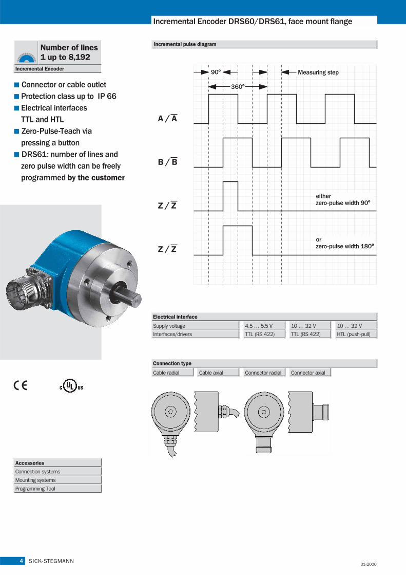
Incremental pulse diagram
Cable radial Cable axial Connector radial Connector axial
A / A
B / B
Z / Z
Z / Z
Measuring step
eitherzero-pulse width 90°
orzero-pulse width 180°
01-2006

10 … 32 V, HTL /push-pullZero-pulse width 180° = F
10 … 32 V, HTL /push-pullZero-pulse width 90° = E
10 … 32 V, TTL /RS 422Zero-pulse width 180° = D
10 … 32 V, TTL /RS 422Zero-pulse width 90° = C
4.5 … 5.5 V, TTL /RS 422Zero-pulse width 180° = B
Connector M23, 12 pin, radial = A Each number of lines from 00001
up to 08192 possible.
Always 5 characters in clear text.
4.5 … 5.5 V, TTL /RS 422Zero-pulse width 90° = A
5SICK-STEGMANN
DRS60/DRS61
D
Point 1
R
Point 2
S
Point 3
6
Point 4
0
Point 5
–
Point 6 Point 7
4
Point 8 Point 9 Point 10 Point 11 Point 12 Point 13 Point 14
Order information
Incremental Encoder DRS60, face mount flange, solid shaft
Order example Incremental Encoder DRS60
4.5 … 5.5 V, TTL/RS 422 zero-pulse width 90°; face mount flange; connector M23, 12 pin, radial; number of lines: 360
Electrical interface
D
Point 1
R
Point 2
S
Point 3
6
Point 4
0
Point 5
–
Point 6
A
Point 7
4
Point 8
A
Point 9
0
Point 10
0
Point 11
3
Point 12
6
Point 13
0
Point 14
Connection type Number of lines
Connector M23, 12 pin, axial = B
Cable 11 core, radial 1.5 m = K
Cable 11 core, radial 3 m = L
Cable 11 core, radial 5 m = M
Cable 11 core, radial 10 m = N
Cable 11 core, axial 10 m = U
Cable 11 core, axial 1.5 m = R
Cable 11 core, axial 3 m = S
Cable 11 core, axial 5 m = T
Connector M23, 12 pin, radial = A
D
Point 1
R
Point 2
S
Point 3
6
Point 4
1
Point 5
–
Point 6 Point 7
4
Point 8 Point 9
0
Point 10
8
Point 11
1
Point 12
9
Point 13
2
Point 14
Incremental-Encoder DRS61 face mount flange, solid shaft (number of lines and zero pulse width can be freely programmed by the customer)
Order example Incremental Encoder DRS61
4.5 … 5.5 Volt, TTL/RS 422; face mount flange; connector M23, 12 pin, radial; number of lines: 8,192 (factory-programmed)
Electrical interface
4.5 … 5.5 V, TTL /RS 422 = A
10 … 32 V, TTL /RS 422 = C
10 … 32 V, HTL /push-pull = E
D
Point 1
R
Point 2
S
Point 3
6
Point 4
1
Point 5
–
Point 6
A
Point 7
4
Point 8
A
Point 9
0
Point 10
8
Point 11
1
Point 12
9
Point 13
2
Point 14
Connection type Number of lines
Factory-programmed to 8,192.
Connector M23, 12 pin, axial = B
Cable 11 core, radial 1.5 m = K
Cable 11 core, axial 1.5 m = R
NEW
Mechanical interface
Face mount flange, solid shaft 10 mm = 4
Mechanical interface
Face mount flange, solid shaft 10 mm = 4
01-2006
Please order programming tool separately (see accessories page 18)1
1

6
Incremental Encoder DRS60/DRS61, servo flange
Connector or cable outletProtection class up to IP 66Electrical interfaces TTL and HTLZero-Pulse-Teach viapressing a buttonDRS61: number of lines andzero pulse width can be freelyprogrammed by the customer
PIN Signal Wire colour Explanation
(Cable outlet)
1 B black Signal line
2 Sense + grey Connected internally to Us
3 Z lilac Signal line
4 Z yellow Signal line
5 A white Signal line
6 A brown Signal line
7 N. C. orange Not connected
8 B pink Signal line
9 Screen Housing potential
10 GND blue Zero volt connected to the encoder
11 Sense – green Connectedinternally to GND
12 Us red Supply voltage 1)
1) Potential free tohousing
N. C. = Not connected
SICK-STEGMANN
Dimensional drawing servo flange radial
PIN and wire allocation/cable 11 core
View of the connector M23 fitted to the encoder body
1
R = bending radius min. 40 mm1 General tolerances according to DIN ISO 2768-mk
Dimensional drawing servo flange axial
1
R = bending radius min. 40 mm1 General tolerances according to DIN ISO 2768-mk
Accessories
Connection systems
Mounting systems
Programming Tool
Number of lines1 up to 8,192
Incremental Encoder
01-2006

Solid shaft 6 mm
Number of lines per revolution 00001 up to 08192, see order info
Electrical Interface TTL/RS 422, 6-channel
HTL/push-pull, 6-channel
Mass 1) Approx. 0.3 kg
Moment of inertia of the rotor 48 gcm2
Measuring step 90°/number of lines
Reference signal
Number 1
Position 2) 90° or 180°
Error limits
binary number of lines 0.035°
non-binary number of lines 0.046°
Measuring step deviation
binary number of lines 0.005°
non-binary number of lines 0.016°
Max. output frequency
TTL 820 kHz
HTL 200 kHz
Operating torque max.
with shaft seal 6,000 min-1
without shaft seal 3) 10,000 min-1
Max. angular acceleration 5 x 10⁵ rad/s2
Operating torque Typ. 0.2 Ncm
Start up torque Typ. 0.25 Ncm
Permissible shaft loading
radial 20 N
axial 10 N
Bearing lifetime 3.6 x 10 9 revolutions
Working temperature range – 20 … + 85 °C
Storage temperature range – 40 … + 100 °C
Permissible relative humidity 4) 90 %
EMC 5)
Resistance
to shocks 6) 50/11 g/ms
to vibration 7) 20/10 … 2000 g/Hz
Protection class IEC 60529
Connector outlet 8) IP 65
Cable outlet IP 66
Operating voltage range
Load current TTL/RS 422, 4.5 … 5.5 V Max. 20 mA
TTL/RS 422, 10 … 32 V Max. 20 mA
HTL/push-pull, 10 … 32 V Max. 60 mA
No-load operating current
at 10 … 32 V Typ. 100 mA
at 5 V Typ. 120 mA
Operation of zero-set 9) ≥ 100 ms
Initialisation time after power on 40 ms
7SICK-STEGMANN
DRS60/DRS61
Order information see page 9
servo
Technical Data acc. to DIN 32878 DRS60/DRS61 servo flange
5) To DIN EN 61000-6-2and DIN EN 61000-6-3
4) Condensation of the optical scanningnot permitted
6) To DIN EN 60068-2-277) To DIN EN 60068-2-68) With mating connector fitted9) Only with shaft stationary
2) Electrical, logically linked to A and B3) In case, that shaft seal has been
removed by customer
1) Concerning encoder with connector
Flange type
01-2006

8
Incremental Encoder DRS60/DRS61, servo flange
Connector or cable outletProtection class up to IP 66Electrical interfaces TTL and HTLZero-Pulse-Teach viapressing a buttonDRS61: number of lines andzero pulse width can be freelyprogrammed by the customer
SICK-STEGMANN
Accessories
Connection systems
Mounting systems
Programming Tool
Number of lines1 up to 8,192
Incremental Encoder
Incremental pulse diagram
Connection type
Cable radial Cable axial Connector radial Connector axial
Supply voltage
Interfaces/drivers
Electrical interface
4.5 … 5.5 V
TTL (RS 422)
10 … 32 V
TTL (RS 422)
10 … 32 V
HTL (push-pull)
A / A
B / B
Z / Z
Z / Z
Measuring step
eitherzero-pulse width 90°
orzero-pulse width 180°
01-2006

9SICK-STEGMANN
DRS60/DRS61
Order information
D
Point 1
R
Point 2
S
Point 3
6
Point 4
0
Point 5
–
Point 6 Point 7
1
Point 8 Point 9 Point 10 Point 11 Point 12 Point 13 Point 14
Incremental Encoder DRS60, servo flange, solid shaft
Order example Incremental Encoder DRS60
4.5 … 5.5 V, TTL/RS 422 zero-pulse width 90°; servo flange; connector M23, 12 pin, radial; number of lines: 360
Mechanical interfaceElectrical interface
Servo flange, solid shaft 6 mm = 1
D
Point 1
R
Point 2
S
Point 3
6
Point 4
0
Point 5
–
Point 6
A
Point 7
1
Point 8
A
Point 9
0
Point 10
0
Point 11
3
Point 12
6
Point 13
0
Point 14
D
Point 1
R
Point 2
S
Point 3
6
Point 4
1
Point 5
–
Point 6 Point 7
1
Point 8 Point 9
0
Point 10
8
Point 11
1
Point 12
9
Point 13
2
Point 14
Incremental-Encoder DRS61, servo flange, solid shaft (number of lines and zero pulse width can be freely programmed by the customer)
Order example Incremental Encoder DRS61
4.5 … 5.5 Volt, TTL/RS 422; servo flange; connector M23, 12 pin, radial; number of lines: 8,192 (factory-programmed)
D
Point 1
R
Point 2
S
Point 3
6
Point 4
1
Point 5
–
Point 6
A
Point 7
1
Point 8
A
Point 9
0
Point 10
8
Point 11
1
Point 12
9
Point 13
2
Point 14
NEW
10 … 32 V, HTL /push-pullZero-pulse width 180° = F
10 … 32 V, HTL /push-pullZero-pulse width 90° = E
10 … 32 V, TTL /RS 422Zero-pulse width 180° = D
10 … 32 V, TTL /RS 422Zero-pulse width 90° = C
4.5 … 5.5 V, TTL /RS 422Zero-pulse width 180° = B
Connector M23, 12 pin, radial = A Each number of lines from 00001
up to 08192 possible.
Always 5 characters in clear text.
4.5 … 5.5 V, TTL /RS 422Zero-pulse width 90° = A
Connection type Number of lines
Connector M23, 12 pin, axial = B
Cable 11 core, radial 1.5 m = K
Cable 11 core, radial 3 m = L
Cable 11 core, radial 5 m = M
Cable 11 core, radial 10 m = N
Cable 11 core, axial 10 m = U
Cable 11 core, axial 1.5 m = R
Cable 11 core, axial 3 m = S
Cable 11 core, axial 5 m = T
Connector M23, 12 pin, radial = A
Electrical interface
4.5 … 5.5 V, TTL /RS 422 = A
10 … 32 V, TTL /RS 422 = C
10 … 32 V, HTL /push-pull = E
Connection type Number of lines
Factory-programmed to 8,192.
Connector M23, 12 pin, axial = B
Cable 11 core, radial 1.5 m = K
Cable 11 core, axial 1.5 m = R
Mechanical interface
Servo flange, solid shaft 6 mm = 1
01-2006
Please order programming tool separately (see accessories page 18)1
1
10
Incremental Encoder DRS60/DRS61, blind hollow shaft
SICK-STEGMANN
Connector or cable outletProtection class up to IP 66Electrical interfaces TTL and HTLZero-Pulse-Teach viapressing a buttonDRS61: number of lines andzero pulse width can be freelyprogrammed by the customer
Accessories
Connection systems
Mounting systems
Collets
Programming Tool
PIN Signal Wire colour Explanation
(Cable outlet)
1 B black Signal line
2 Sense + grey Connected internally to Us
3 Z lilac Signal line
4 Z yellow Signal line
5 A white Signal line
6 A brown Signal line
7 N. C. orange Not connected
8 B pink Signal line
9 Screen Housing potential
10 GND blue Zero volt connected to the encoder
11 Sense – green Connectedinternally to GND
12 Us red Supply voltage 1)
1) Potential free tohousing
N. C. = Not connected
Dimensional drawing blind hollow shaft radial
Dimensional drawing blind hollow shaft axial
PIN and wire allocation/cable 11 core
View of the connector M23 fitted to the encoder body
1
1
R = bending radius min. 40 mm1
R = bending radius min. 40 mm1
General tolerances according to DIN ISO 2768-mk
General tolerances according to DIN ISO 2768-mk
Insertion depth of mounting shaftmin. 15 mm, max. 30 mm
Insertion depth of mounting shaftmin. 15 mm, max. 30 mm
Number of lines1 up to 8,192
Incremental Encoder
01-2006

Hollow shaft diameter 6, 8, 10, 12, 15 mm, 1/4", 3/8", 1/2"
Number of lines per revolution 00001 up to 08192, see order info
Electrical Interface TTL/RS 422, 6-channel
HTL/push-pull, 6-channel
Mass 1) Approx. 0.3 kg
Moment of inertia of the rotor See Fig. 1
Measuring step 90°/number of lines
Reference signal
Number 1
Position 2) 90° or 180°
Error limits
binary number of lines 0.035°
non-binary number of lines 0.046°
Measuring step deviation
binary number of lines 0.005°
non-binary number of lines 0.016°
Max. output frequency
TTL 820 kHz
HTL 200 kHz
Operating torque max. 3,000 min-1
Max. angular acceleration 5 x 10⁵ rad/s2
Operating torque Typ. 0.4 Ncm
Start up torque Typ. 0.6 Ncm
Permissible movement of the
drive element
radial static/dynamic movement ± 0.3/± 0.1 mm
axial static/dynamic movement ± 0.5/± 0.2 mm
Bearing lifetime 3.6 x 10 9 revolutions
Working temperature range – 20 … + 85 °C
Storage temperature range – 40 … + 100 °C
Permissible relative humidity 3) 90 %
EMC 4)
Resistance
to shocks 6) 50/11 g/ms
to vibration 6) 20/10 … 2000 g/Hz
Protection class IEC 60529
Connector outlet 7) IP 65
Cable outlet IP 66
Operating voltage range
Load current TTL/RS 422, 4.5 … 5.5 V Max. 20 mA
TTL/RS 422, 10 … 32 V Max. 20 mA
HTL/push-pull, 10 … 32 V Max. 60 mA
No-load operating current
at 10 … 32 V Typ. 100 mA
at 5 V Typ. 120 mA
Operation of zero-set 8) ≥ 100 ms
Initialisation time after power on 40 ms
11SICK-STEGMANN
DRS60/DRS61
Order information see page 13
blind
Technical Data acc. to DIN 32878 DRS60/DRS61 blind hollow shaft
Fig. 1mm
gcm2
15
42 48 54
6
Flange type
4) To DIN EN 61000-6-2and DIN EN 61000-6-3
3) Condensation of the optical scanningnot permitted
5) To DIN EN 60068-2-276) To DIN EN 60068-2-67) With mating connector fitted8) Only with shaft stationary
2) Electrical, logically linked to A and B
1) Concerning encoder with connector
01-2006

12
Incremental Encoder DRS60/DRS61, blind hollow shaft
SICK-STEGMANN
Connector or cable outletProtection class up to IP 66Electrical interfaces TTL and HTLZero-Pulse-Teach viapressing a buttonDRS61: number of lines andzero pulse width can be freelyprogrammed by the customer
Accessories
Connection systems
Mounting systems
Collets
Programming Tool
Number of lines1 up to 8,192
Incremental Encoder
Incremental pulse diagram
Connection type
Cable radial Cable axial Connector radial Connector axial
Supply voltage
Interfaces/drivers
Electrical interface
4.5 … 5.5 V
TTL (RS 422)
10 … 32 V
TTL (RS 422)
10 … 32 V
HTL (push-pull)
A / A
B / B
Z / Z
Z / Z
Measuring step
eitherzero-pulse width 90°
orzero-pulse width 180°
01-2006

13SICK-STEGMANN
Order information
DRS60/DRS61
D
Point 1
R
Point 2
S
Point 3
6
Point 4
0
Point 5
–
Point 6 Point 7
A
Point 8 Point 9 Point 10 Point 11 Point 12 Point 13 Point 14
Incremental Encoder DRS60, blind hollow shaft
Order example Incremental Encoder DRS60
4.5 … 5.5 V, TTL/RS 422 zero-pulse width 90°; blind hollow shaft; connector M23, 12 pin, radial; number of lines: 360
D
Point 1
R
Point 2
S
Point 3
6
Point 4
0
Point 5
–
Point 6
A
Point 7
A
Point 8
A
Point 9
0
Point 10
0
Point 11
3
Point 12
6
Point 13
0
Point 14
2029174
Part no.
SPZ-006-AD-A
Type Shaft diameter
6 mm
Blind hollow shaft collets
SPZ-1E4-AD-A 2029175 1/4"
SPZ-008-AD-A 2029176 8 mm
SPZ-3E8-AD-A 2029177 3/8"
SPZ-010-AD-A 2029178 10 mm
SPZ-012-AD-A 2029179 12 mm
SPZ-1E2-AD-A 2029180 1/2"
Blind hollow shaft1) = A
D
Point 1
R
Point 2
S
Point 3
6
Point 4
1
Point 5
–
Point 6 Point 7
A
Point 8 Point 9
0
Point 10
8
Point 11
1
Point 12
9
Point 13
2
Point 14
Incremental-Encoder DRS61 blind hollow shaft (number of lines and zero pulse width can be freely programmed by the customer)
Order example Incremental Encoder DRS61
4.5 … 5.5 Volt, TTL/RS 422; blind hollow shaft; connector M23, 12 pin, radial; number of lines: 8,192 (factory-programmed)
D
Point 1
R
Point 2
S
Point 3
6
Point 4
1
Point 5
–
Point 6
A
Point 7
A
Point 8
A
Point 9
0
Point 10
8
Point 11
1
Point 12
9
Point 13
2
Point 14
1) Collets for 6, 8, 10, 12 mm and 1/4",3/8" and 1/2" as accessories, separateorder item (see below).For 15 mm shaft diameter, collet is notneeded.
Mechanical interface
NEW
10 … 32 V, HTL /push-pullZero-pulse width 180° = F
10 … 32 V, HTL /push-pullZero-pulse width 90° = E
10 … 32 V, TTL /RS 422Zero-pulse width 180° = D
10 … 32 V, TTL /RS 422Zero-pulse width 90° = C
4.5 … 5.5 V, TTL /RS 422Zero-pulse width 180° = B
Connector M23, 12 pin, radial = A Each number of lines from 00001
up to 08192 possible.
Always 5 characters in clear text.
4.5 … 5.5 V, TTL /RS 422Zero-pulse width 90° = A
Electrical interface Connection type Number of lines
Connector M23, 12 pin, axial = B
Cable 11 core, radial 1.5 m = K
Cable 11 core, radial 3 m = L
Cable 11 core, radial 5 m = M
Cable 11 core, radial 10 m = N
Cable 11 core, axial 10 m = U
Cable 11 core, axial 1.5 m = R
Cable 11 core, axial 3 m = S
Cable 11 core, axial 5 m = T
Connector M23, 12 pin, radial = A
Electrical interface
4.5 … 5.5 V, TTL /RS 422 = A
10 … 32 V, TTL /RS 422 = C
10 … 32 V, HTL /push-pull = E
Connection type Number of lines
Factory-programmed to 8,192.
Connector M23, 12 pin, axial = B
Cable 11 core, radial 1.5 m = K
Cable 11 core, axial 1.5 m = R
Blind hollow shaft1) = A1) Collets for 6, 8, 10, 12 mm and 1/4",
3/8" and 1/2" as accessories, separateorder item (see below).For 15 mm shaft diameter, collet is notneeded.
Mechanical interface
01-2006
Please order programming tool separately (see accessories page 18)1
1

14
Incremental Encoder DRS60/DRS61, through hollow shaft
SICK-STEGMANN
Connector or cable outletProtection class up to IP 66Electrical interfaces TTL and HTLZero-Pulse-Teach viapressing a buttonDRS61: number of lines andzero pulse width can be freelyprogrammed by the customer
PIN Signal Wire colour Explanation
(Cable outlet)
1 B black Signal line
2 Sense + grey Connected internally to Us
3 Z lilac Signal line
4 Z yellow Signal line
5 A white Signal line
6 A brown Signal line
7 N. C. orange Not connected
8 B pink Signal line
9 Screen Housing potential
10 GND blue Zero volt connected to the encoder
11 Sense – green Connectedinternally to GND
12 Us red Supply voltage 1)
1) Potential free tohousing
N. C. = Not connected
Dimensional drawing through hollow shaft radial
PIN and wire allocation/cable 11 core
View of the connector M23 fitted to the encoder body
1
R = bending radius min. 40 mm1 General tolerances according to DIN ISO 2768-mk
Insertion depth of mounting shaftmin. 15 mm
Accessories
Connection systems
Mounting systems
Collets
Programming Tool
Number of lines1 up to 8,192
Incremental Encoder
01-2006
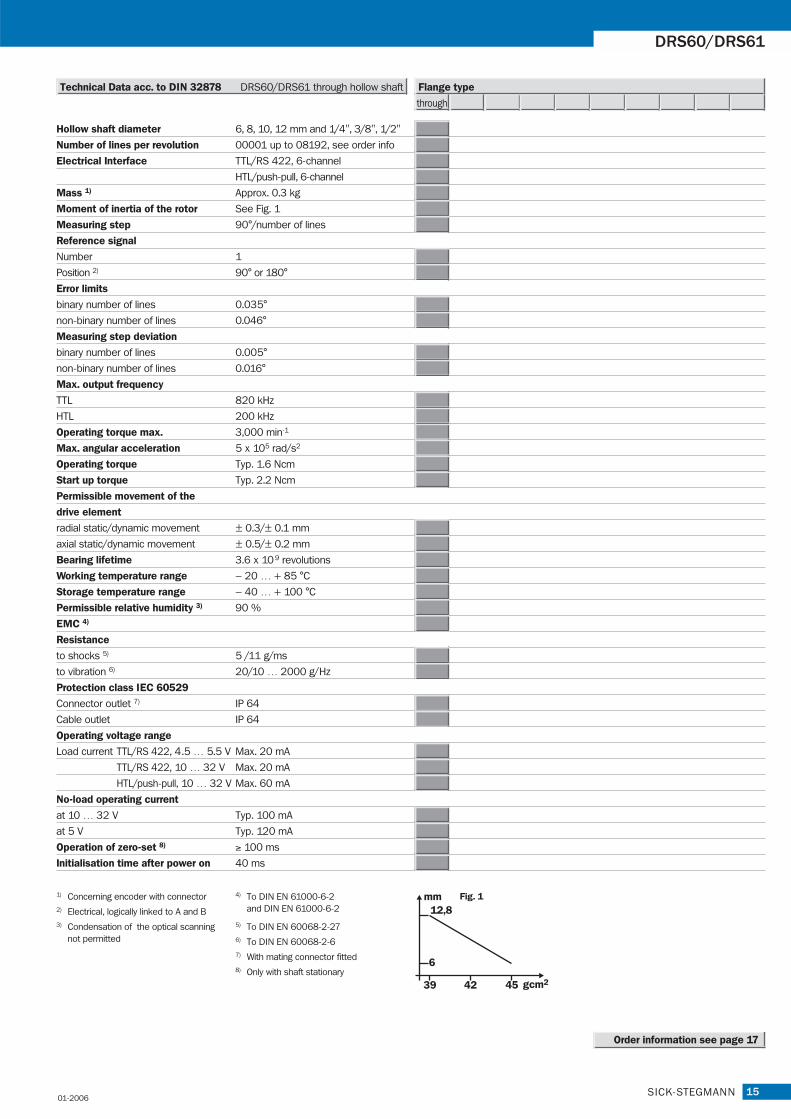
Hollow shaft diameter 6, 8, 10, 12 mm and 1/4", 3/8", 1/2"
Number of lines per revolution 00001 up to 08192, see order info
Electrical Interface TTL/RS 422, 6-channel
HTL/push-pull, 6-channel
Mass 1) Approx. 0.3 kg
Moment of inertia of the rotor See Fig. 1
Measuring step 90°/number of lines
Reference signal
Number 1
Position 2) 90° or 180°
Error limits
binary number of lines 0.035°
non-binary number of lines 0.046°
Measuring step deviation
binary number of lines 0.005°
non-binary number of lines 0.016°
Max. output frequency
TTL 820 kHz
HTL 200 kHz
Operating torque max. 3,000 min-1
Max. angular acceleration 5 x 10⁵ rad/s2
Operating torque Typ. 1.6 Ncm
Start up torque Typ. 2.2 Ncm
Permissible movement of the
drive element
radial static/dynamic movement ± 0.3/± 0.1 mm
axial static/dynamic movement ± 0.5/± 0.2 mm
Bearing lifetime 3.6 x 10 9 revolutions
Working temperature range – 20 … + 85 °C
Storage temperature range – 40 … + 100 °C
Permissible relative humidity 3) 90 %
EMC 4)
Resistance
to shocks 5) 5 /11 g/ms
to vibration 6) 20/10 … 2000 g/Hz
Protection class IEC 60529
Connector outlet 7) IP 64
Cable outlet IP 64
Operating voltage range
Load current TTL/RS 422, 4.5 … 5.5 V Max. 20 mA
TTL/RS 422, 10 … 32 V Max. 20 mA
HTL/push-pull, 10 … 32 V Max. 60 mA
No-load operating current
at 10 … 32 V Typ. 100 mA
at 5 V Typ. 120 mA
Operation of zero-set 8) ≥ 100 ms
Initialisation time after power on 40 ms
15SICK-STEGMANN
DRS60/DRS61
Order information see page 17
through
Technical Data acc. to DIN 32878 DRS60/DRS61 through hollow shaft Flange type
4) To DIN EN 61000-6-2and DIN EN 61000-6-2
3) Condensation of the optical scanningnot permitted
5) To DIN EN 60068-2-276) To DIN EN 60068-2-67) With mating connector fitted8) Only with shaft stationary
2) Electrical, logically linked to A and B
1) Concerning encoder with connector Fig. 1mm
gcm2
12,8
39 42 45
6
01-2006

16
Incremental Encoder DRS60/DRS61, through hollow shaft
SICK-STEGMANN
Connector or cable outletProtection class up to IP 66Electrical interfaces TTL and HTLZero-Pulse-Teach viapressing a buttonDRS61: number of lines andzero pulse width can be freelyprogrammed by the customer
Accessories
Connection systems
Mounting systems
Collets
Programming Tool
Number of lines1 up to 8,192
Incremental Encoder
Incremental pulse diagram
Connection type
Cable radial Connector radial
Supply voltage
Interfaces/drivers
Electrical interface
4.5 … 5.5 V
TTL (RS 422)
10 … 32 V
TTL (RS 422)
10 … 32 V
HTL (push-pull)
A / A
B / B
Z / Z
Z / Z
Measuring step
eitherzero-pulse width 90°
orzero-pulse width 180°
01-2006
17SICK-STEGMANN
DRS60/DRS61
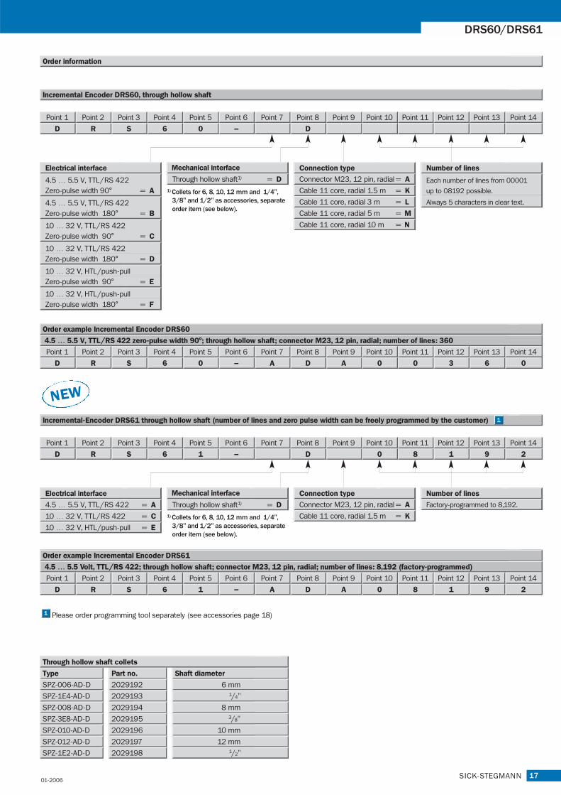
Order information
D
Point 1
R
Point 2
S
Point 3
6
Point 4
0
Point 5
–
Point 6 Point 7
D
Point 8 Point 9 Point 10 Point 11 Point 12 Point 13 Point 14
Incremental Encoder DRS60, through hollow shaft
Connector M23, 12 pin, radial = A
Cable 11 core, radial 1.5 m = K
Cable 11 core, radial 3 m = L
Cable 11 core, radial 5 m = M
Cable 11 core, radial 10 m = N
Connection type
Part no.Type Shaft diameter
Through hollow shaft collets
2029192SPZ-006-AD-D 6 mm
SPZ-1E4-AD-D 2029193 1/4"
SPZ-008-AD-D 2029194 8 mm
SPZ-3E8-AD-D 2029195 3/8"
SPZ-010-AD-D 2029196 10 mm
SPZ-012-AD-D 2029197 12 mm
SPZ-1E2-AD-D 2029198 1/2"
Through hollow shaft1) = D
D
Point 1
R
Point 2
S
Point 3
6
Point 4
1
Point 5
–
Point 6 Point 7
D
Point 8 Point 9
0
Point 10
8
Point 11
1
Point 12
9
Point 13
2
Point 14
Incremental-Encoder DRS61 through hollow shaft (number of lines and zero pulse width can be freely programmed by the customer)
Order example Incremental Encoder DRS61
4.5 … 5.5 Volt, TTL/RS 422; through hollow shaft; connector M23, 12 pin, radial; number of lines: 8,192 (factory-programmed)
Mechanical interface
D
Point 1
R
Point 2
S
Point 3
6
Point 4
1
Point 5
–
Point 6
A
Point 7
D
Point 8
A
Point 9
0
Point 10
8
Point 11
1
Point 12
9
Point 13
2
Point 14
Number of lines
1) Collets for 6, 8, 10, 12 mm and 1/4",3/8" and 1/2" as accessories, separateorder item (see below).
Connector M23, 12 pin, radial = A
Cable 11 core, radial 1.5 m = K
Connection type
Factory-programmed to 8,192.
NEW
Order example Incremental Encoder DRS60
4.5 … 5.5 V, TTL/RS 422 zero-pulse width 90°; through hollow shaft; connector M23, 12 pin, radial; number of lines: 360
D
Point 1
R
Point 2
S
Point 3
6
Point 4
0
Point 5
–
Point 6
A
Point 7
D
Point 8
A
Point 9
0
Point 10
0
Point 11
3
Point 12
6
Point 13
0
Point 14
10 … 32 V, HTL /push-pullZero-pulse width 180° = F
10 … 32 V, HTL /push-pullZero-pulse width 90° = E
10 … 32 V, TTL /RS 422Zero-pulse width 180° = D
10 … 32 V, TTL /RS 422Zero-pulse width 90° = C
4.5 … 5.5 V, TTL /RS 422Zero-pulse width 180° = B
Each number of lines from 00001
up to 08192 possible.
Always 5 characters in clear text.
4.5 … 5.5 V, TTL /RS 422Zero-pulse width 90° = A
Electrical interface Number of lines
Electrical interface
4.5 … 5.5 V, TTL /RS 422 = A
10 … 32 V, TTL /RS 422 = C
10 … 32 V, HTL /push-pull = E
Through hollow shaft1) = D1) Collets for 6, 8, 10, 12 mm and 1/4",
3/8" and 1/2" as accessories, separateorder item (see below).
Mechanical interface
01-2006
Please order programming tool separately (see accessories page 18)1
1
18
Accessories Programming Tool/Connection systems/Mounting systems
SICK-STEGMANN
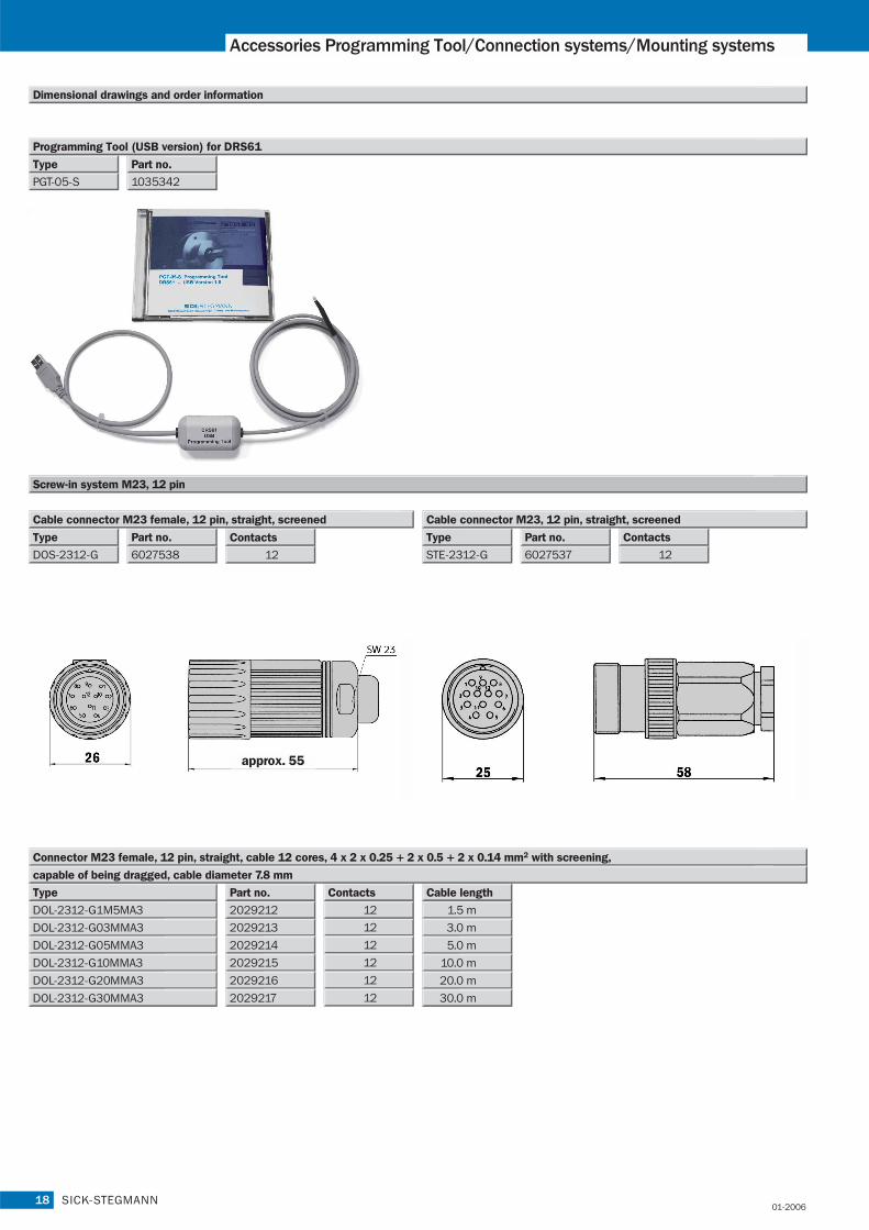
Dimensional drawings and order information
Screw-in system M23, 12 pin
6027538
Part no.
DOS-2312-G
Type
STE-2312-G
Type
12
Contacts
12
Contacts
6027537
Part no.
Cable connector M23 female, 12 pin, straight, screened Cable connector M23, 12 pin, straight, screened
approx. 55
2029213
DOL-2312-G1M5MA3
DOL-2312-G03MMA3
Type
12
12
Contacts
2029212
Part no.
1.5 m
3.0 m
2029214DOL-2312-G05MMA3 12 5.0 m
2029215DOL-2312-G10MMA3 12 10.0 m
20292162DOL-2312-G20MMA3 12 20.0 m
20292172DOL-2312-G30MMA3 12 30.0 m
Cable length
Connector M23 female, 12 pin, straight, cable 12 cores, 4 x 2 x 0.25 + 2 x 0.5 + 2 x 0.14 mm2 with screening,
capable of being dragged, cable diameter 7.8 mm
01-2006
1035342
Part no.
PGT-05-S
Type
Programming Tool (USB version) for DRS61

19SICK-STEGMANN
DRS60/DRS61
6027529
Part no.
LTG-2308-MWENC
Type
8
Wires
6027530
Part no.
LTG-2411-MW
Type
11
Wires
Cable 11 core, per meter, 4 x 2 x 0.25 + 2 x 0.5 + 1 x 0.14 mm2
with screening, cable diameter 7.5 mm
Cable 8 core, per meter, 4 x 2 x 0.15 mm2 with screening,
cable diameter 5.6 mm
6027531
Part no.
LTG-2512-MW
Type
12
Wires
6028516LTG-2612-MW 12 UV and salt water resistant
Explanation
Cable 12 core, per meter, 4 x 2 x 0.25 + 2 x 0.5 + 2 x 0.14 mm2
with screening, capable of being dragged, cable diameter 7.8 mm
Dimensional drawings and order information
Couplings
5312981
Part no.
KUP-0606-B
Type Shaft diameter
5312985
Part no.
KUP-0610-F
Type Shaft diameter
6 mm … 10 mm
5312986KUP-1010-F 10 mm … 10 mm
5312982KUP-0610-B
5312983KUP-1010-B
5312984KUP-1012-B
Bellows coupling, max. shaft offset radial ± 0.3 mm, axial 0.4 mm, angle ± 4 degrees, torsion spring stiffness 120 Nm/rad,
bellows of stainless steel, hubs of aluminium
Spring-disc coupling, max. shaft offset radial ± 0.3 mm, axial 0.4 mm, angle ± 2.5 degrees, torsion spring stiffness 50 Nm/rad,
flange of aluminium, spring-discs of glass-fibre-reinforced plastic
General tolerances according to DIN ISO 2768-mk
Cheese-head screwM2,5x8 DIN912 A2
6 mm … 6 mm
6 mm … 10 mm
10 mm … 10 mm
10 mm … 12 mm
01-2006

20
Accessories Mounting systems
SICK-STEGMANN
BEF-FA-036-050
Dimensional drawings and order information
Mechanical Adaptors
2029160
Part no.Type Adaption
To 50 mm servo flange
Adaptor flange of aluminium for face mount flange, spigot 36 mm
BEF-FA-036-060REC 2029162
Part no.Type Adaption
To 60 mm square mounting plate
Adaptor flange of aluminium for face mount flange, spigot 36 mm
BEF-FA-036-060RSA 2029163
Part no.Type Adaption
To 60 mm square mounting plate with shock absorbers
Adaptor flange of aluminium for face mount flange, spigot 36 mm
Spring washer (4x)
Hexagonal nut (4x)(secure with Loctite 241)
deep
)
01-2006

21SICK-STEGMANN
DRS60/DRS61
Dimensional drawings and order information
Mechanical Adaptors
5312987BEF-MG-50 Diameter 50 mm
Part no.Type Flange spigot
Mounting bell incl. fixing set for encoder with servo flange
2029164BEF-WF-36 Diameter 36 mm
Part no.Type Flange spigot
Mounting angle incl. fixing set for encoder with face mount flange
2029165BEF-WG-SF050
Part no.Type 2029166BEF-WK-SF
Part no.Type
Servo clamps small, Set (comprises 3 pieces) for servo flanges
with spigot diameter 50 mm
Servo clamps half ring, Set (comprises 2 pieces) for servo flanges
01-2006

22
Accessories mounting systems/Collets
SICK-STEGMANN
Collets
2029174
Part no.
SPZ-006-AD-A
Type Shaft diameter
6 mm
Part no.Type Shaft diameter
Collets for blind hollow shaft encoder Collets for through hollow shaft encoder
5312988BEF-MR-010020
Part no.
0.2 m
CircumferenceType
5312989BEF-MR-010050
Part no.
0.5 m
CircumferenceType
rial plastic (Hytrel), wheel material plastic with aluminium hub
Measuring wheel for encoder shafts with diameter 10 mm, type mate-
rial plastic (Hytrel), wheel material plastic with aluminium hub
Measuring wheel for encoder shafts with diameter 10 mm, type mate-
SPZ-1E4-AD-A 2029175 1/4"
SPZ-008-AD-A 2029176 8 mm
SPZ-3E8-AD-A 2029177 3/8"
SPZ-010-AD-A 2029178 10 mm
SPZ-012-AD-A 2029179 12 mm
SPZ-1E2-AD-A 2029180 1/2"
2029192SPZ-006-AD-D 6 mm
SPZ-1E4-AD-D 2029193 1/4"
SPZ-008-AD-D 2029194 8 mm
SPZ-3E8-AD-D 2029195 3/8"
SPZ-010-AD-D 2029196 10 mm
SPZ-012-AD-D 2029197 12 mm
SPZ-1E2-AD-D 2029198 1/2"
Dimensional drawings and order information
Mechanical Adaptors
01-2006

23SICK-STEGMANN
DRS60/DRS61
01-2006

8 0
10 3
04
/01
-06
• M
D/6
/20
00
• P
rinte
d in
Ger
man
y (0
6.0
5)
• S
ubje
ct to
cha
nge
with
out p
rior
notic
e •
The
spec
ified
pro
duct
feat
ures
and
tech
nica
l dat
a do
not
repr
esen
t any
gua
rant
ee •
01
A4
Stg
2c
int2
2
Contact:
A u s t r a l i aPhone +61 3 9497 4100
1800 33 48 02 – tollfreeE-Mail [email protected]
B e l g i u m / L u x e m b o u r gPhone +32 (0)2 466 55 66E-Mail [email protected]
B r a s i lPhone +55 11 5091-4900E-Mail [email protected]
C e s k á R e p u b l i k aPhone +420 2 57 91 18 50E-Mail [email protected]
C h i n aPhone +852-2763 6966E-Mail [email protected]
D a n m a r kPhone +45 45 82 64 00E-Mail [email protected]
D e u t s c h l a n dPhone +49 (0)2 11 53 01-250E-Mail [email protected]
E s p a ñ aPhone +34 93 480 31 00E-Mail [email protected]
F r a n c ePhone +33 1 64 62 35 00E-Mail [email protected]
G r e a t B r i t a i nPhone +44 (0)1727 831121E-Mail [email protected]
I n d i aPhone +91 (11)2696 7651E-Mail [email protected]
I t a l i aPhone +39 011 79 79 65E-Mail [email protected]
J a p a nPhone +81 (0)3 3358 1341E-Mail [email protected]
K o r e aPhone +82-2 786 6321/4E-Mail [email protected]
N e d e r l a n d sPhone +31 (0)30 229 25 44E-Mail [email protected]
N o r g ePhone +47 67 81 50 00E-Mail [email protected]
Ö s t e r r e i c hPhone +43 (0)22 36 62 28 8-0E-Mail [email protected]
P o l s k aPhone +48 22 837 40 50E-Mail [email protected]
R e p u b l i k a S l o w e n i j aPhone +386 (0)1-47 69 990E-Mail [email protected]
R u s s i aPhone +7 95 775 05 30E-Mail [email protected]
S c h w e i zPhone +41 41 619 29 39E-Mail [email protected]
S i n g a p o r ePhone +65 6744 3732E-Mail [email protected]
S u o m iPhone +358-9-25 15 800E-Mail [email protected]
S v e r i g ePhone +46 8 680 64 50E-Mail [email protected]
T ü r k i y ePhone +90 216 388 95 90 pbxE-Mail [email protected]
T a i w a nPhone +886 2 2365-6292E-Mail [email protected]
U S APhone +1 937-454-1956E-Mail [email protected]
More representatives and agencies in all major industrial nations at www.sick.com
SICK AG • Industrial Sensors • Waldkirch • Germany • www.sick.comSICK STEGMANN GmbH • Donaueschingen • Germany • www.sick-stegmann.de