druck pitot static testers - industrialto maintain its accreditation with the accuracy of the pitot...
TRANSCRIPT

Druck Pitot Static TestersHave you considered what is verifyingyour RVSM compliant Aircraft?
1
DRUCK PITOT STATIC TESTERS GE Air Data Test Sets

2
DRUCK PITOT STATIC TESTERS GE Air Data Test Sets
IntroductionThe Druck business within GE Measurement and Controls has been developing and delivering pressure sensors and pressure measurement and calibration equipment for more than 40 Years.
The current products (the ADTS 500 and 405 families) have Druck’s TERPS® (Trench Etched Resonant Pressure Sensor) technology at their core, which delivers unprecedented metrological characteristics and resultant levels of performance in the field.
This paper focuses on the main characteristics of Pitot Static Testers (also known as Air Data Test Sets) and highlights several items that should be considered pertaining to their specifications or behaviours under certain conditions. Before choosing an instrument for Aircraft calibration, there are many factors that need to be addressed including the following:
• A clear definition of what is meant by the accuracy specification
• Confirmation that all factors are included in the accuracy specification
• A clear definition of what is meant by the precision specification
• The importance of controller stability and the degree of offset from the instrument’s stated capability, as well as the impact of environmental factors that will affect the instrument – such as fluid density, fluid humidity, temperature and EMC (Electromagnetic Compatibility).
Druck’s philosophy is to provide customers with solutions aligned to their needs, where specifications meet customers’ requirements and to provide openness and transparency on the company’s instruments’ capabilities. Druck uses achieved performance data and and therefore has no need to use caveats, hidden definitions and small print in describing the products’ capabilities. Druck’s ADTS (Air Data Test Sets) have the metrological characteristics to be suitable for testing aircraft to the RVSM standard.
RVSMReduced Vertical Separation Minima or Minimum (RVSM) is the reduction of the standard vertical separation required between aircraft flying between FL290 (29,000 feet) and FL410 (41,000 feet) inclusive, from 2,000 feet to 1,000 feet (or between 8,850 and 12,500 metres from 600 metres to 300 metres).
RVSM compliance – an aircraft must be verified to be compliant and fly within these limits.
RVSM compliance is a term that is often misinterpreted and misused. The RVSM regulations describe the verification of the Aircraft flying within the 29,000 feet to 41,000 feet airspace with a vertical separation of 1,000 feet. Each aircraft has to have completed a series of tests and checks to maintain its accreditation with the accuracy of the Pitot static test set required to confirm the accuracy of the readings within the Aircraft.
It is a common practice to claim Pitot Static Testers are “RVSM compliant”.
There is no reference to the pitot static tester within the RVSM regulations, as only the aircraft itself can be deemed to be compliant with the RVSM regulations. Users should review the metrological characteristics, such as accuracy, drift and precision of these pitot static testers to determine their suitability for use on specific aircraft systems.
AccuracyAs per the VIM (Vocabulaire International de Métrologie) definition, accuracy is a qualitative term, defined as “closeness of agreement between a measured quantity value and a true quantity value of a measurand.” However, often in the aerospace industry accuracy is interpreted as a quantitative term. The term “accuracy” should be associated with the specified measurement error, including the impact of systematic error, random error and drift (in cases where accuracy is specified over a period of time). Definitions of accuracy should consider the application and the needs of the customer.
3
DRUCK PITOT STATIC TESTERS GE Air Data Test Sets
-0.60 -0.50 -0.40 -0.30 -0.20 -0.10 0.00 0.10 0.20 0.30 0.40 0.50 0.60
0.00
0.02
0.04
0.06
0.08
0.10
0.12
0.14
0.16
Expanded Uncertainty includingcalibration standard
Expanded Uncertainty totalExpanded Uncertainty Precision
Prob
abili
ty
100,000 trials
mbar
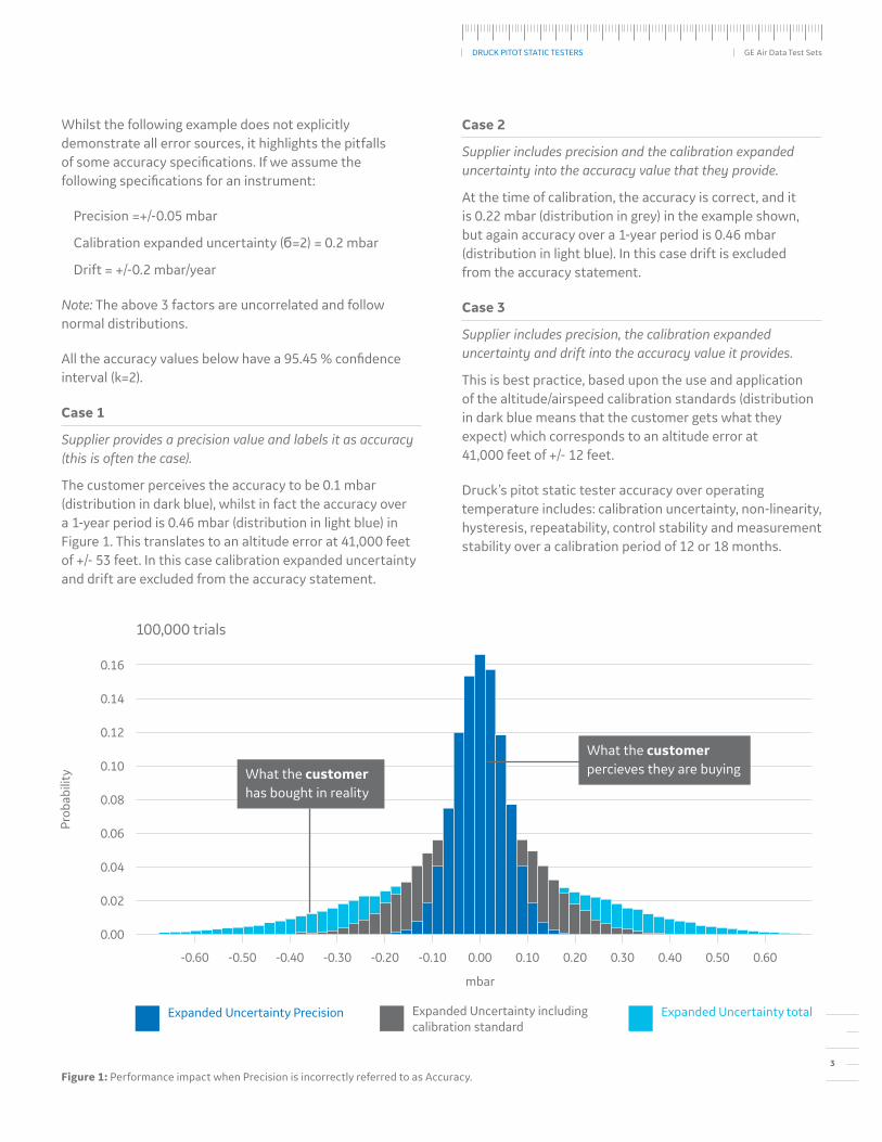
Whilst the following example does not explicitly demonstrate all error sources, it highlights the pitfalls of some accuracy specifications. If we assume the following specifications for an instrument:
Precision =+/-0.05 mbar
Calibration expanded uncertainty (б=2) = 0.2 mbar
Drift = +/-0.2 mbar/year
Note: The above 3 factors are uncorrelated and follow normal distributions.
All the accuracy values below have a 95.45 % confidence interval (k=2).
Case 1
Supplier provides a precision value and labels it as accuracy (this is often the case).
The customer perceives the accuracy to be 0.1 mbar (distribution in dark blue), whilst in fact the accuracy over a 1-year period is 0.46 mbar (distribution in light blue) in Figure 1. This translates to an altitude error at 41,000 feet of +/- 53 feet. In this case calibration expanded uncertainty and drift are excluded from the accuracy statement.
Case 2
Supplier includes precision and the calibration expanded uncertainty into the accuracy value that they provide.
At the time of calibration, the accuracy is correct, and it is 0.22 mbar (distribution in grey) in the example shown, but again accuracy over a 1-year period is 0.46 mbar (distribution in light blue). In this case drift is excluded from the accuracy statement.
Case 3
Supplier includes precision, the calibration expanded uncertainty and drift into the accuracy value it provides.
This is best practice, based upon the use and application of the altitude/airspeed calibration standards (distribution in dark blue means that the customer gets what they expect) which corresponds to an altitude error at 41,000 feet of +/- 12 feet.
Druck’s pitot static tester accuracy over operating temperature includes: calibration uncertainty, non-linearity, hysteresis, repeatability, control stability and measurement stability over a calibration period of 12 or 18 months.
Figure 1: Performance impact when Precision is incorrectly referred to as Accuracy.
What the customer has bought in reality
What the customer percieves they are buying
100,000 trials

4
DRUCK PITOT STATIC TESTERS GE Air Data Test Sets
As mentioned earlier, there are many different examples of how manufacturers of pitot static testers define accuracy, however a close examination can reveal the flaws of several of these definitions of accuracy. As an example: a case where the accuracy is very close to resolution of the device (the resolution equates to 41 % of the accuracy):
Pressure function
Range: 1 to 32 inHg
Resolution 0.001 inHg
Accuracy 0.002 inHg
Figure 2: Datasheet specification of accuracy and resolution.
DriftDrift is a very important metrological characteristic, as it will often dictate the accuracy of the instrument between two successive calibrations or how often altitude or airspeed calibration standards should be calibrated, which involves both time and cost for the user.
The graph in Figure 3 represents the typical drift for Druck’s Trench Etched Resonant Pressure Sensor (Druck’s TERPS®) and compares its drift performance over time against the drift performance claimed and achieved by other instrument manufacturers. Whilst Druck’s specification includes a 30 ppm FS drift per annum, Druck has observed that the drift performance of Druck’s TERPS® over time outperforms the specification. As more data is gathered this will be reflected in the accuracy specification and the re-calibration period.
Before purchasing any pitot static tester, the buyer should investigate whether the accuracy value stated includes drift for the recalibration period. If not, then the accuracy figures stated are valid only at the point of calibration and not over the course of time between calibrations. Knowing this will help to calculate the total cost of ownership of a pitot static tester.
Figure 3: Druck’s TERPS® drift performance versus market specifications.
Druck’s drift specification allows for 30ppm FS. This covers the maximum potential variability in Druck’s TERPS®’ performance. However, as figure 3 shows the achieved drift performance is better than the specification indicates.
50 100 150 200 250 300 350 4000
0
20
40
60
80
100
120
Days
-20
Claimed Piezoresistive SensorDrift Spec ppm FS
Druck’s TERPS® Drift ppm FS
Typical Piezoresistive Sensor Drift Spec ppm FS
ppm
TERPS drift behaviour v market speci�cationsDruck’s TERPS® drift behaviour v market specifications
5
DRUCK PITOT STATIC TESTERS GE Air Data Test Sets
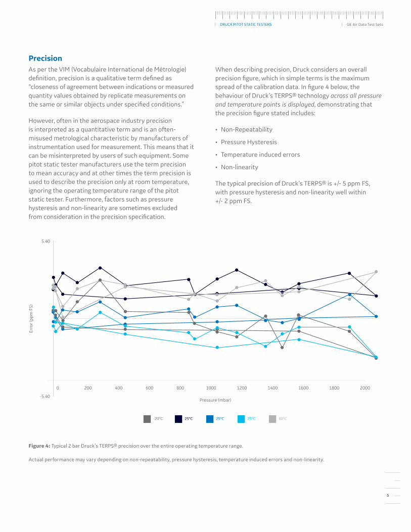
PrecisionAs per the VIM (Vocabulaire International de Métrologie) definition, precision is a qualitative term defined as “closeness of agreement between indications or measured quantity values obtained by replicate measurements on the same or similar objects under specified conditions.”
However, often in the aerospace industry precision is interpreted as a quantitative term and is an often-misused metrological characteristic by manufacturers of instrumentation used for measurement. This means that it can be misinterpreted by users of such equipment. Some pitot static tester manufacturers use the term precision to mean accuracy and at other times the term precision is used to describe the precision only at room temperature, ignoring the operating temperature range of the pitot static tester. Furthermore, factors such as pressure hysteresis and non-linearity are sometimes excluded from consideration in the precision specification.
When describing precision, Druck considers an overall precision figure, which in simple terms is the maximum spread of the calibration data. In figure 4 below, the behaviour of Druck’s TERPS® technology across all pressure and temperature points is displayed, demonstrating that the precision figure stated includes:
• Non-Repeatability
• Pressure Hysteresis
• Temperature induced errors
• Non-linearity
The typical precision of Druck’s TERPS® is +/- 5 ppm FS, with pressure hysteresis and non-linearity well within +/- 2 ppm FS.
Figure 4: Typical 2 bar Druck’s TERPS® precision over the entire operating temperature range.
5.40
-5.40
Erro
r (pp
m F
S)
200 400 600 800 1000 1200 1400 1600 18000 2000
Pressure (mbar)
25°C 60°C-20ºC 25°C 25ºC
Actual performance may vary depending on non-repeatability, pressure hysteresis, temperature induced errors and non-linearity.

6
DRUCK PITOT STATIC TESTERS GE Air Data Test Sets
Density Sensitivity of the Measuring SensorOne type of pressure sensor used in some pitot static testers is a vibrating cylinder sensor and whilst it has the potential to be accurate, it comes with some limitations.
The vibrating cylinder sensing element is in direct contact with the pressure media and is fundamentally a density sensor. As the pressure in the system changes, the density of the gas changes and it is this that is measured by the sensor, as opposed to the pressure that is directly applied. This means that vibrating cylinder technologies are media sensitive; albeit with a lot of care and the addition of a humidity sensor good repeatability can still be achieved.
Reproducibility is another issue. The reproducibility relies on having the exact same gas mixture present during the calibration of the pitot static tester present when doing the aircraft calibration. Humidity of the air in the system has a significant effect upon sensor performance. Figure 5 shows the humidity errors with just a 10% change in humidity, demonstrating that the errors are greater at higher gas temperatures and pressure range. Without humidity correction it is not possible to meet 0.1 mbar accuracy required for the test system over the normal operating range of a pitot static tester due to the change of humidity and temperature.
Figure 5: Pressure offset dependency relative to humidity.
1310mbar F.S. Vibrating cylinder Pressure o�set for 10%increase in RH
Erro
r (m
bar)
-20 0 20 40 60 80
-0.20
-0.18
-0.16
-0.14
-0.12
-0.10
-0.08
-0.06
-0.04
-0.02
0.00
Temperature (degrees celsius)
1310mbar F.S. Vibrating cylinder Pressure offset for 10% increase in Relative Humidity
7
DRUCK PITOT STATIC TESTERS GE Air Data Test Sets
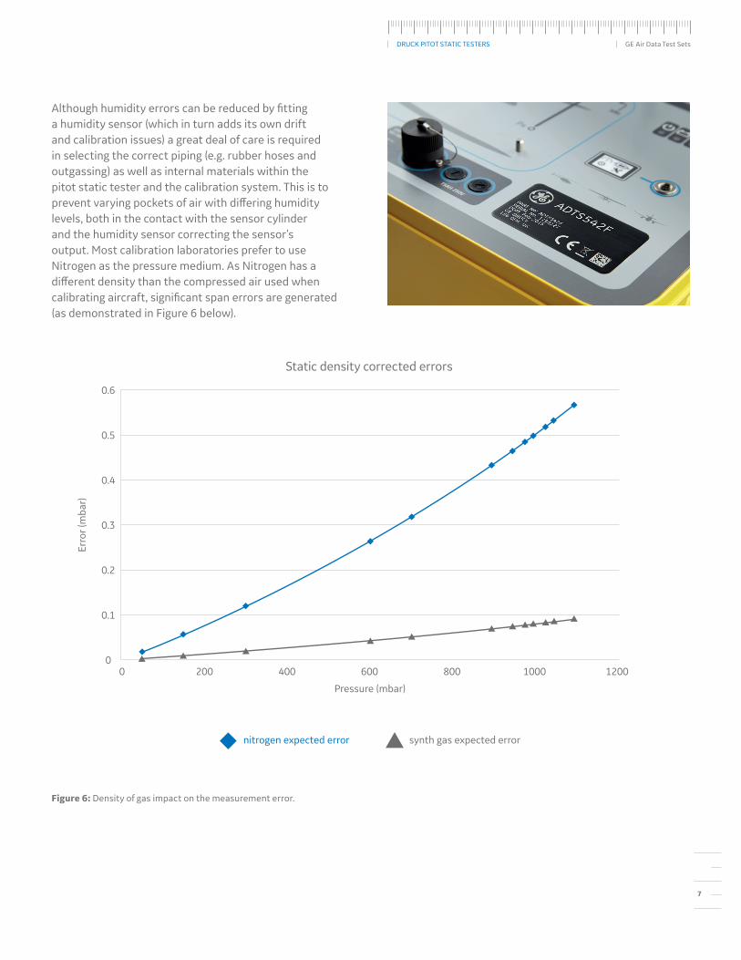
Although humidity errors can be reduced by fitting a humidity sensor (which in turn adds its own drift and calibration issues) a great deal of care is required in selecting the correct piping (e.g. rubber hoses and outgassing) as well as internal materials within the pitot static tester and the calibration system. This is to prevent varying pockets of air with differing humidity levels, both in the contact with the sensor cylinder and the humidity sensor correcting the sensor’s output. Most calibration laboratories prefer to use Nitrogen as the pressure medium. As Nitrogen has a different density than the compressed air used when calibrating aircraft, significant span errors are generated (as demonstrated in Figure 6 below).
Figure 6: Density of gas impact on the measurement error.
Pressure (mbar)
Erro
r (m
bar)
0 200 400 600 800 1000 12000
0.1
0.2
0.3
0.4
0.5
0.6
nitrogen expected error synth gas expected error
Static density corrected errorsStatic density corrected errors

8
DRUCK PITOT STATIC TESTERS GE Air Data Test Sets
Control Stability and Offset ImportanceThis is an often-overlooked factor and should be considered in the overall uncertainty evaluation. The market trend to reduce cost and size has led to some systems not being able to maintain a controlled pressure into all the variations of piping and system volumes which are used across the aviation industry. This means in some cases that the controller must be turned off to have a near-stable pressure reading (Aircraft system leaks can then make it difficult to take accurate measurements, as pressure will shift towards ambient pressure at an uncontrolled rate).
Two factors need to be considered, controller noise and controller offset.
Controller offset is simply the average difference between the commanded value and the controlled pressure. Controller noise is the deviation of the pressure around the average controlled pressure. This is shown in figure 7.
In attempting to quantify what is classed as good control performance, when describing pressure noise in terms of margin of error expressed in parts per million and if the pressure controller range is 1,128 mbar, the table below shows the pressure error for the corresponding ppm value.
Older controllers have a controller noise of 50ppm whereas Druck’s pitot static testers within the ADTS500 series have a best in class controller noise of less than 5ppm with no significant offset.
Controller noise PPM Pressure error mbar
50 0.050
20 0.023
10 0.011
5 0.006
Figure 7: Controller offset and noise.
Erro
r (m
bar)
Readings
Controller o�set and noise
-0.06
-0.04
-0.02
0.00
0.02
0.04
0.06
0.08
0.1
0.12
0 1 2 3 4 5 6 7 8 9 10
Controller o�set
controller average pressure controller noisecommanded pressure
Controller offset and noise

9
DRUCK PITOT STATIC TESTERS GE Air Data Test Sets
Height Allowable Correction The fluid head correction (the difference between the reference level of the pitot static tester and the aircraft reference level) should be corrected every time the aircraft avionics are verified and/or calibrated using the pitot static tester. Generally, the head correction is easily inputted into the pitot static tester’s memory before starting the testing.
As can be seen in Figure 8 below, the fluid head error can easily exceed the accuracy of the pitot static tester (+/-3 feet at sea level to +/-12 feet at 41,000 feet) if not corrected.
As the fluid density changes with applied pressure, the fluid head error remains reasonably consistent with the change in altitude, albeit slightly worse at lower altitude.
Figure 8: Fluid Head Error Effect on Accuracy.
Aircraft Calibration Fluid Head Error E�ect at Di�erent Altitudes
Uncorrected Height (feet)
Flui
d H
ead
Erro
r (fe
et)
0 5 10 15 20 250
2
4
6
8
10
12
14
16
18
20
Fluid Head Error at 10,000 feet Fluid Head Error at 29,000 feetFluid Head Error at 1,000 feet Fluid Head Error at 41,000 feet
Aircraft Calibration Fluid Head Error Effect at Different Altitudes

10
DRUCK PITOT STATIC TESTERS GE Air Data Test Sets
CE Marking and Radio Emissions ComplianceA factor that is commonly overlooked is the infl uence of the electromagnetic environment that a product is used within. All electronic measurement instruments are susceptible to electromagnetic interference, either conducted into the unit via the power/signal cable or via “pick up” from radiated signals. The unwanted disturbances in the electronics can aff ect the sensor and/or the measurement system resulting in signifi cant measurement errors. This is also further compounded when using wireless communications within modern instruments. At the same time the pitot static tester itself can emit interference that can aff ect other nearby products or even the aircraft avionics themselves.
As part of CE (Conformité Européenne) requirements, manufacturers shall test their product to demonstrate that the unit maintains the correct output during radiated/conducted susceptibility and emissions testing and whilst the wireless radio is operating within the product. It is worth mentioning that FCC (Federal Communications Commission) testing for the North American market requires no such susceptibility testing and therefore the supplier may not even be aware that their product has a susceptibility issue. The CE certifi cate provided by the supplier should be inspected to ensure that the CE mark covers all the relevant testing requirements (such as EMC, electrical safety, pressure equipment directive and the radio equipment directive) for the environment that the product will be used within.
An example of such diff erent environments is a standard industrial location, where the radiated susceptibility limits are 10V/m (EN61326), whereas for a military aircraft carrier the level is signifi cantly higher at 200V/m (mil-std-461). In this instance the CE marking alone will not be suffi cient to ensure that the measurement accuracy is maintained. This is an extreme example, but if users are in any doubt Druck can provide guidance on the suitability of its products within the environment in which they will be operating. There are pitot static testers available which are not marked with the CE logo or with the equivalent local regulatory markings, such as wireless labelling. Pitot static tester buyers are advised to investigate the accuracy, suitability and compliance of the product and its use in the operating region(s) and environment(s) prior to the purchase of the instrument.
ConclusionRVSM compliance is specifi c to each aircraft and so customers are advised to fully investigate the total uncertainty of their pitot static system and the tester used to validate this. Druck’s TERPS® technology has enabled Druck to produce a family of ADTS products that account for stability, NLHR (Non-Linearity, Hysteresis and Repeatability) and drift performance, across the entire spectrum of environmental conditions. By producing a series of products with in-house developed best-in-class sensing technology at their core and the supporting team’s understanding and application of metrological characteristics that underpin instrument and Aircraft performance in the fi eld, Druck’s pitot static testers lead the market.
THE AUTHORS OF THIS PAPER ARE:
Neculai Moisoi, PhD – Senior Metrologist
Neil Sands, SEng – Senior Pressure Controllers Designer
Tom Piggin, MEng CEng MIET – Lead Pressure Controllers Designer
Timothy Sparkes, IEng MIET - Capability Development Leader
Philip Bradley, CEng – Senior ADTS Application Engineer
Nigel Scoggins, MSc – Product Manager - ADTS
For all enquiries please visit https://bit.ly/2KGFPnP
Copyright 2018 Baker Hughes, a GE company, LLC. All rights reserved. GE and the GE Monogram are trademarks of the General Electric Company.