drum & container pumps - aiqsa
TRANSCRIPT

DRUM & CONTAINER PUMPSOPERATION & SERVICE GUIDE
OI-100CSEPT. 2003
AIQSAC/Adrià Gual, 2 - 43206 Reus
Tel. +34 977 31 21 68Fax +34 977 31 35 19
e-mail: [email protected]

TABLE OF CONTENTSPage
3
4 - 7
7
8 - 11
11
12
13
14
15
16
17
18
19
20
21
22
23
24
27
Section 1 - Start-up and general information
Section 2 - Instructions for electric motors
Section 3 - Instructions for pneumatic motors
Section 4 - Instruction for pump tubes
Repair section
Section 5 - Carbon brush replacement
Polypropylene pump spare parts
CPVC pump spare parts
High temperature polypropylene spare parts
PVDF pump spare parts
Stainless pump spare parts
A-1 motor spare parts
A-2 motor spare parts
SP-280P series spare parts
SP-ODP series spare parts
SP-ENC series spare parts
SP-400 series spare parts
Section 6 - Hazardous duty set-up
Certificate of conformity and warranty
2

BEFORE OPERATING THIS EQUIPMENT, THE OPERATORSHOULD THOROUGHLY READ AND UNDERSTAND ALL
INSTRUCTIONS AND SAFETY WARNING LABELS INCLUDING THEMANUFACTURER'S INSTRUCTIONS ON THE MATERIAL BEINGPUMPED.
SECTION 1: GENERAL1. The operator should wear suitable protective clothing including: face mask,
safety shield or goggles, gloves, apron, and safety shoes.2. Check a chemical resistance chart to be sure the chemical being pumped
is compatible with pump construction.3. Flammable or combustible liquids can only be handled with air driven
motors and explosion-proof electric motors in conjunction with stainlesssteel pump tubes.
4. The use of SP-PP tubes (polypropylene), SP-PVDF (polyvinylidenefluoride), SP-CPVC (CPVC), and SP-PHT (High temp. polypropylene),SP-280P, SP-ODP series motors (open) or SP-ENC series motors (TEFC)on flammable or combustible liquids is prohibited and could cause fire, injuryor death.
5. Bonding and grounding safety procedures as described in National FireProtection Code 77 must be used when handling flammables, operating ina hazardous duty environment or when the danger of static discharge ispresent. Avoid liquid splashing. Refer to Section 6.
6. All federal, state and local safety codes should be followed.7. Make sure nameplate information corresponds to voltagesupplied.
PRE-START-UP1. All connections must be properly in place and tightened securely.
Stainless steel hose clamps are required on hose and must be properlytightened. Pump hand wheel must be snug, otherwise pump couplingdamage can occur.
2. Since all pump motors and pump tubes are interchangeable, it isnecessary for the operator to read and understand operating instructionsfor both the motor and the pump tube.
3. First use pump on water to be familiar with the assembly and check motoroperation, flow rate, security of all hose connections, operation of speedcontrol knob, liquid velocity, pump drainage and dispensing nozzle.
4. Before starting motor, check to be sure hose is securely fastened inreceiving vessel so hose cannot splash chemicals, causing injury.
5. Before connecting motor to power supply, be sure motor switch is OFF("O" position) and speed control is turned down.
6. Never submerge pump below the hose connection.7. Never leave unit unattended during operation.8. Do not use speed control knob as ON/OFF switch.*9. If liquid appears below discharge assembly, check security of hose clamps
and wing nut. If leakage fails to stop, cease operation. Neutralize pump andrefer to specific parts list and operating instructions to repair. If unable torepair, contact factory.
DRUM PUMPS
3

10. When finished using pump, drain pump and hose thoroughly and operateon 1-2 gallons of clear water or neutral solution for 15-30 seconds tocompletely flush and rinse pump and hose assembly.
11. Never store the pump and hose assembly in the container. Always rinsethoroughly and hang on a wall bracket.
* The speed control switch should not be used as the main ON/OFF switch. Using the speed control switch in this manner causes excessive wear to the
potentiometer and triac and may result in premature failure. The use ofthe speed control switch does not cut power to the motor and inadvertentactivation could result in injury or death if the motor is activated when notproperly attended and secured.
SECTION 2: INSTRUCTIONS FOR MOTORS -SP-280P Series, SP-ENC Series, SP-ODP Series and SP-400Series
THIS EQUIPMENT (SP-280P, SP-ENC, SP-ODP, SP-400) MUST BE CONNECTED TO A GROUND FAULT CURRENT
INTERRUPTION DEVICE BEFORE OPERATING.
SP-280P, SP-280P-V listedOpen Drip Proof enclosure, 115V/1/50-60Hz-1.1 HP (825 watts) - 10,000 RPM,
thermal overload protection switch, manual reset on switch, 16 ft. SJT U.L. listed,3 wire cord with 3 prong molded plug.SP-280P-2 , SP-280P-2-V listed
Open Drip Proof enclosure (IP 44), 220V/1/50-60Hz-1.1 HP (825 watts) -10,000 RPM, thermal overload protection switch, Low Voltage Release (LVR),16 ft. (5 m) CE listed, Har Ho 7 cable cord with plug.1. Do not use the SP-280P series motor on flammables or in hazardous duty
environments.2. Check nameplate data to verify proper voltage.3. Before connecting plug to power supply, be sure motor switch is in the OFF
position, "O".4. Never carry motor by or pull on power cord.5. If the supply cord is damaged, it must be replaced by a special cord or
assembly available from the manufacturer or its service agent.6. If motor stops during operation, place the switch in the OFF position "O"
and allow the motor to cool. Motor will not restart if the switch is notplaced in the OFF position. 220V Models - LVR will release motor switchwhen voltage is interrupted or stopped. Motor will not turn on once poweris restored.
7. Check viscosity and specific gravity limitations before resuming operation.8. Connect power cord to suitable receptacle and never remove ground prong
from plug.9. To engage motor to pump tube, place motor on top of pump tube and turn
hand wheel part #1842 clockwise until the motor coupling and pumpcoupling are completely engaged and secured.
10. To replace cartridge brushes, refer to Section 5.11. Never submerge motor in liquid or splash motor with liquid. Operation of
motor in wet conditions can cause injury or death.
4

12. Variable Speed Models (SP280P-V, SP280P-2-V) Make sure the speedcontrol knob is turned in the OFF position before starting operation. Turnswitch handle to the ON position and slowly turn the speed control knobto the right. The pump will begin to slowly transfer. The variable speedcontrol should not be used as the main ON/OFF switch. This is consid-ered excessive wear and may result in premature failure. See #8 in thePre-Start-Up section.
13. Bond and ground where the possibility of static discharge is present.
SP-ENC, SP-ENC-V listedTEFC enclosure, 115V/1/50-60Hz - 1.1 HP (825 watts) -10,000 RPM,
thermal overload protection switch, manual reset on switch, 16 ft. SJT U.L. listed,3 wire cord with 3 prong molded plug.
SP-ENC-2, SP-ENC-2-V listedTEFC (IP 54) enclosure, 220V/1/50-60Hz - 1.1 HP (825 watts) - 10,000 RPM,
thermal overload protection switch, Low Voltage Release (LVR), 16 ft. (5 m) CElisted, Har Ho 7 cable cord with plug.
The SP-ENC series motor is a totally enclosed fan cooled motor (TEFC).The construction of a TEFC motor minimizes corrosive fumes from entering anddamaging the vital internal components of the motor. The SP-ENC is idealwhere corrosive fumes present a detriment to the operation of open motors.1. Do not use the SP-ENC series motor on flammables or in hazardous duty
environments.2. Check nameplate data to verify proper voltage.3. Before connecting plug to power supply, be sure motor switch is in the
OFF position, "O".4. Never carry motor by or pull on power cord.5. If the supply cord is damaged, it must be replaced by a special cord or
assembly available from the manufacturer or its service agent.6. If motor stops during operation, place the switch in the OFF position
"O" and allow the motor to cool.Motor will not restart if the switch is not placed in the OFF position.220V models - LVR will release motor switch when voltage is interruptedor stopped. Motor will not turn on once power is restored.
7. Check viscosity and specific gravity limitations before resumingoperation.
8. Connect power cord to suitable receptacle and never remove ground prongfrom plug.
9. To engage motor to pump tube, place motor on top of pump tube and turnhand wheel part #1842 clockwise until the motor coupling and pumpcoupling are completely engaged and secured.
10. To replace cartridge brushes, refer to Section 5.11. Never submerge motor in liquid or splash motor with liquid.12. Variable Speed Models (SP-ENC-V, SP-ENC-2-V) Make sure the speed
control knob is turned in the OFF position before starting operation. Turnswitch handle to the ON position and slowly turn the speed controlknob to the right. The pump will begin to slowly transfer. The variablespeed control should not be used as the main ON/OFF switch. This is
5

considered excessive wear and may result in premature failure. See #8 inthe Pre-Start-Up section.
13. Bond and ground where the possibility of static discharge is present.SP-ODP
Open Drip Proof enclosure, 115V/1/50-60Hz-½ HP (450 watts) - 10,000 RPM,thermal overload protection switch, manual reset switch, 16 ft. power cord.3-wire cord with molded plug.1. Do not use the SP-ODP series motor on flammables or in hazardous duty
environments.2. Check nameplate data to verify proper voltage.3. Before connecting plug to power supply, be sure motor switch is in the OFF
position, "O".4. Never carry motor by or pull on power cord.5. If the supply cord is damaged, it must be replaced by a special cord or
assembly available from the manufacturer or its service agent.6. If motor stops during operation, place the switch in the OFF position "O"
and allow the motor to cool. Motor will not restart if the switch is notplaced in the OFF position. 220V Models - LVR will release motor switchwhen voltage is interrupted or stopped. Motor will not turn on once poweris restored.
7. Check viscosity and specific gravity limitations before resuming operation.8. Connect power cord to suitable receptacle and never remove ground prong
from plug.9. To engage motor to pump tube, place motor on top of pump tube and turn
hand wheel part #1842 clockwise until the motor coupling and pumpcoupling are completely engaged and secured.
10. To replace cartridge brushes, refer to Section 5.11. Never submerge motor in liquid or splash motor with liquid. Operation of
motor in wet conditions can cause injury or death.12. Bond and ground where the possibility of static discharge is present.SP-ODP-2
Open Drip Proof enclosure, 230V/1/50-60Hz-½ HP (450 watts) - 10,000 RPM,thermal overload protection switch, manual reset switch, 16 ft. power cord.3-wire cord with molded plug.1. Do not use the SP-ODP series motor on flammables or in hazardous duty
environments.2. Check nameplate data to verify proper voltage.3. Before connecting plug to power supply, be sure motor switch is in the OFF
position, "O".4. Never carry motor by or pull on power cord.5. If the supply cord is damaged, it must be replaced by a special cord or
assembly available from the manufacturer or its service agent.6. If motor stops during operation, place the switch in the OFF position "O"
and allow the motor to cool. Motor will not restart if the switch is notplaced in the OFF position. 220V Models - LVR will release motor switchwhen voltage is interrupted or stopped. Motor will not turn on once poweris restored.
7. Check viscosity and specific gravity limitations before resuming operation.8. Connect power cord to suitable 3 prong receptacle and never remove ground
prong from plug.
6
9. To engage motor to pump tube, place motor on top of pump tube and turnhand wheel part #1842 clockwise until the motor coupling and pumpcoupling are completely engaged and secured.
10. To replace cartridge brushes, refer to Section 5.11. Never submerge motor in liquid or splash motor with liquid. Operation of
motor in wet conditions can cause injury or death.12. Bond and ground where the possibility of static discharge is present.
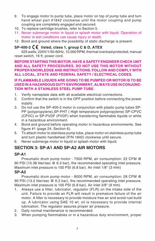
SP-400-2 listed, class 1, group C & D, ATEX625 watts, 220V/1/50-60Hz, 10,000 RPM, thermal overload protected, manual
reset switch, 16 ft. power cord.
BEFORE STARTING THIS MOTOR, HAVE A SAFETY ENGINEER CHECK UNITAND ALL SAFETY PROCEDURES. DO NOT USE THIS MOTOR WITHOUTPROPER KNOWLEDGE AND INSTRUCTIONS. FOLLOW AND COMPLY WITHALL LOCAL, STATE AND FEDERAL SAFETY / ELECTRICAL CODES.
IF FLAMMABLE LIQUIDS ARE GOING TO BE PUMPED OR MOTOR IS TO BEUSED IN A HAZARDOUS DUTY ENVIRONMENT, ALWAYS USE IN CONJUNC-TION WITH A STAINLESS STEEL PUMP TUBE.
1. Verify nameplate data with all available electrical connections.2. Confirm that the switch is in the OFF position before connecting the power
supply.3. Do not use the SP-400-2 motor in conjunction with plastic pump tubes SP-
PP (polypropylene),SP-PHT ( High temperature polypropylene) SP-CPVC(CPVC) or SP-PVDF (PVDF) when transferring flammable liquids or whilein a hazardous environment.
4. Bond and ground before operating motor in hazardous environments. Seefigure #1 (page 24, Section 6).
5. To attach motor to stainless pump tube, place motor on stainless pump tubeand turn plastic handwheel (P/N 1842) clockwise until secure.
6. Never submerge motor in liquid or splash motor with liquid.
SECTION 3: SP-A1 AND SP-A2 AIR MOTORS
SP-A1Pneumatic drum pump motor - 7500 RPM, air consumption: 22 CFM @
90 PSI (10.38 liter/sec @ 6.3 bar), the recommended operating inlet pressure.Maximum inlet pressure is 100 PSI (6.8 bar). Air Inlet 1/8" (3 mm)SP-A2
Pneumatic drum pump motor - 8000 RPM, air consumption: 28 CFM @90 PSI (13.2 liter/sec @ 6.2 bar), the recommended operating inlet pressure.Maximum inlet pressure is 100 PSI (6.8 bar). Air inlet 3/8" (9 mm)1. Always use a filter, lubricator, regulator (FLR) on the intake side of the
unit. Failure to provide an FLR will result in premature failure of the airmotor. A filter is necessary to provide moisture free air and avoid rust buildup. A lubricator using SAE 10 wt. oil is necessary to provide internallubrication. The regulator assures proper air pressure.
2. Daily normal maintenance is recommended.3. When pumping flammables or in a hazardous duty environment, proper
7

8
bonding and grounding is required according to NFPA 77 to avoid staticelectric discharge. See Fig. 2 (page 24, Section 6).
4. Never use the SP-A1 or SP-A2 motors in conjunction with plastic pumptubes SP-PP (polypropylene), SP-PVDF (PVDF), SP-CPVC (CPVC) orSP-PHT (High temperature polypropylene) when pumping flammables orin a hazardous duty environment.
5. If motor slows down or stops, disconnect air supply from motor removemotor from pump. Turn the motor shaft with your finger; it should turneasily. If it does not, check your lubricator to be sure air motor is receivingproper lubrication.
6. Check the muffler to make sure it is not clogged. A safety solvent can beused to clean the clogged muffler. A clogged muffler will cause backpressure and prevent the unit from working freely.
7. Never stand directly in path of muffler exhaust.8. Never operate the air motor without the muffler in place and tightened
properly.9. Before operation make sure the motor is securely fastened to the pump
with the handwheel, part #1842. Improper connection will result in damageto the pump coupling and possibly the pump shaft.
SECTION 4: INSTRUCTIONS FOR PUMP TUBES:polypropylene, CPVC, PVDF and stainless steel
All pump tubes are engineered with a seal-less design. Pumps can rundry and against back pressure without damage to the integrity of the pump.
MODEL NUMBER KEY = Example: SP-PP-39SP = Standard PumpPP = polypropylene39 = tube length 39" (1000 mm)
SP-PPPolypropylene construction - Hastelloy drive shaft -FPM -seal - FPM sealed
ball bearings - TFE guide sleeve - carbon grade 6038C carbon bushing - hoseconnection 1" (25 mm), ¾" (22mm) available. Maximum temperature 130°F (55°C).1. Do not use SP-PP pump tubes on flammables or in hazardous duty
environments. The insulating nature of plastic prevents proper bondingand grounding. A static electric discharge can take place and ignite fumesresulting in fire, injury or death.
2. SP-PP pumps can be run dry without damaging the structural integrity ofthe unit. Prolonged periods of dry running should be avoided.
3. Always check the chemical compatibility of the liquid being pumped withpump construction and hose you have selected.
4. Securely tighten all connections before beginning operation.5. Before starting motor, check to be sure hose is securely fastened in
receiving vessel so hose cannot splash chemicals, causing injury.6. Check temperature limitation, pressure rating and chemical compatibility
of the hose you have selected.7. Never submerge pump below the hose connection.8. If liquid appears below discharge housing, part #1028, check security of
9
hose clamps and wing nut, part #1106. If leakage fails to stop, ceaseoperation. Neutralize pump and return unit to an authorized StandardPump distributor for inspection and possible repair.
SP-PVDFPVDF (polyvinylidene fluoride) construction - natural PVDF contains no
pigment or color and is ideal for the transfer of concentrated chemicals -Hastelloy® C-276 drive shaft - TFE V-seal FPM sealed ball bearings -TFE guidesleeve - pure carbon grade 6038C carbon bushing - hose connection 1" (25 mm),¾" (22 mm). Maximum temperature 175°F (80°C) maximum.
1. Do not use SP-PVDF pump tubes on flammables or in hazardous duty en-vironments. The insulating nature of plastic prevents proper bondingand grounding. A static electric discharge can take place and ignite fumesresulting in fire, injury or death.
2. SP-PVDF pump can run dry without damaging the structural integrityof the unit. Prolonged periods of dry running should be avoided.
3. Always check the chemical compatibility of the liquid being pumped withpump construction and hose you have selected.
4. Securely tighten all connections before beginning operation.5. Before beginning operation, check to be sure hose is securely fastened in
receiving vessel. Failure to secure hose properly will allow hose to splashchemicals, causing injury.
6. Check temperature limitation, pressure rating and chemical compatibilityof the hose you have selected.
7. Never submerge pump below the hose connection.8. If liquid appears below discharge housing, part #4028, check security of
hose clamps and wing nut, part #4106. If leakage fails to stop, ceaseoperation. Neutralize pump and return unit to an authorized StandardPump distributor for inspection and possible repair.
SP-SSStainless steel 316 construction - TFE rotor - TFE V-seal - TFE guide sleeve,
stainless drive shaft, - pure carbon grade 6038C carbon bushing - FPM sealedball bearings - 1" (25 mm) hose connection. Maximum temperature 175°F (80°C).1. SP-SS pumps can be run dry without damaging the structural integrity of
the unit. Prolonged periods of dry running should be avoided.2. Always check the chemical compatibility of the liquid being pumped with
pump construction and hose you have selected.3. Check temperature limitation, pressure rating and chemical compatibility
of the hose you have selected.4. Securely tighten all connections before beginning operation. Use only
stainless steel hose clamps to secure hose and tighten securely. Use ofoptional hand clamp is recommended. See Catalog.
5. The SP-SS requires a TFE seal #2195 between the wing nut and pumpbody. Be sure this "O"-ring is in place or leakage of chemicals will occur.
6. When using the SP-SS on flammables or in hazardous duty environments,it is always necessary to bond and ground as per NFPA 77. See Fig. 1(page 24 Section 6) for illustration.

10
7. An electrically conductive hose may be employed with the SP-SS tubewhen pumping flammables. Installation must be exactly to manufacturer'sinstallation instructions. Bonding and grounding must also be used inconjunction with hose to prevent static electric discharge.
8. If liquid appears below the bearing housing, re-check security of all fittings.Re-check to be sure the TFE seal #2195 is in place. If leakage continues,cease operation, neutralize the pump and return it to an authorizedStandard Pump distributor for inspection and possible repair.
SP-CPVCCPVC construction, Hastelloy C 276 drive shaft, TFE V-seal. FPM sealed
ball bearings, TFE guide sleeve, carbon bushing, 1" (25mm) or ¾" (22mm) hosebarb available. Temperature limitation 190° F (90°C)
1. Do not use SP-CPVC pump tubes on flammables or in hazardous dutyenvironments. The insulating nature of plastic prevents proper bondingand grounding. A static electric discharge can take place and ignite fumesresulting in fire, injury or death.
2. SP-CPVC pumps can be run dry without damaging the structural integrityof the unit. Prolonged periods of dry running should be avoided.
3. Always check the chemical compatibility of the liquid being pumped withpump construction and hose you have selected.
4. Securely tighten all connections before beginning operation.5. Before starting motor, check to be sure hose is securely fastened in
receiving vessel so hose cannot splash chemicals, causing injury.6. Check temperature limitation, pressure rating and chemical compatibility
of the hose you have selected.7. Never submerge pump below the hose connection.8. If liquid appears below discharge housing, part #5028, check security of
hose clamps and wing nut, part #5106. If leakage fails to stop, ceaseoperation. Neutralize pump and return unit to an authorized StandardPump distributor for inspection and possible repair.
SP-PHTPolypropylene construction, Hastelloy C 276 drive shaft, TFE V-seal. FPM
sealed ball bearings, TFE guide sleeve, carbon bushing, 1" (25mm) or ¾" (22mm)hose barb available. Temperature limitation 190° F (90°C)
1. Do not use SP-PHT pump tubes on flammables or in hazardous dutyenvironments. The insulating nature of plastic prevents proper bondingand grounding. A static electric discharge can take place and ignite fumesresulting in fire, injury or death.
2. SP-PHT pumps can be run dry without damaging the structural integrity ofthe unit. Prolonged periods of dry running should be avoided.
3. Always check the chemical compatibility of the liquid being pumped withpump construction and hose you have selected.
4. Securely tighten all connections before beginning operation. Use onlystainless steel hose clamps to secure hose and tighten securely.
5. Before starting motor, check to be sure hose is securely fastened inreceiving vessel so hose cannot splash chemicals, causing injury.

11
6. Check temperature limitation, pressure rating and chemical compatibilityof the hose you have selected.
7. Never submerge pump below the hose connection.8. If liquid appears below discharge housing, part #6028, check security of
hose clamps and wing nut, part #6106. If leakage fails to stop, ceaseoperation. Neutralize pump and return unit to an authorized StandardPump distributor for inspection and possible repair.
REPAIR SECTIONAll SP-PP (polypropylene), SP-PVDF (PVDF), SP-CPVC (CPVC), SP-SS(stainless) and SP-PHT (high temperature polypropylene) pumps arerepaired in the same steps.
Impeller, Pump Coupling (1004) and Pump Foot replacement1. Unplug motor, remove motor from pump and store safely. Remove pump from
solution and neutralize or flush with water.2. Unscrew pump foot in a clockwise direction. (NOTE: left handed threads).
This will expose the impeller.3. Secure 1004 pump coupling on opposite end. Use a flat head screwdriver to
unscrew the impeller in a counter-clockwise direction.4. Replace impeller and pump foot in opposite order. NOTE: If 1004 pump
coupling loosens instead of the impeller, simply hold shaft with pliers andunscrew impeller. Take care not to damage threads on shaft.
Pump Housing Replacement1. Unplug motor, remove motor from pump and store safely. Remove pump
from solution and neutralize or flush with water.2. Unscrew pump foot in a clockwise direction. (NOTE: left handed threads).
This will expose the impeller.3. Secure 1004 pump coupling on opposite end. Use a flat head screwdriver
to unscrew the rotor in a counter- clockwise direction. NOTE: If 1004 couplingloosens instead of the impeller, simply hold the shaft with pliers, takingcare not to damage the shaft threads.
4. Unscrew the pump housing in a clockwise direction. NOTE the left handedthreads.
5. Replace new components in opposite order.
SECTION 5: REPLACEMENT OF CARTRIDGE BRUSHES -SP-280P AND SP-ENC MOTORS (Consult factory for brushreplacement on other models.)
THE REPLACEMENT OF BRUSHES OR ANY ELECTRICAL WORK SHOULD ONLY BE PERFORMED BY A LICENSED
ELECTRICIAN OR BY PLANT PERSONNEL FULLY TRAINED INELECTRICAL REPAIR.
1. Disconnect motor from power supply and pump tube.2. Place motor on a flat table in the upright position.3. Remove fan cover screws. Be careful not to lose the wave washer or drop it
into motor windings.

12
4. On the SP-ENC (TEFC), it is necessary to next remove the fan and thebearing cover. Again, be careful of the wave washer.
5. Back out screw holding the clamp over the brush cartridge. Do not fullyremove the screw or clamp.
6. Gently push brush cartridge toward the armature and lift up from the motorhousing side.
TO INSTALL NEW BRUSH CARTRIDGE:
7. Check to be sure the brush plate is properly located in the brush channel.The brush plate has a tab that sits on the armature side of the brush holder.Do not allow the brush plate to come in contact with the armature or ashort circuit will occur. Do not position the brush plate where it willcontact the motor housing or an electrical short circuit will occur, causinginjury or death.
8. Push cartridge gently forward and down in the brush channel. The brasslocator pins will fit into the locking channel. The cartridge can only go inone way. Re-check the connector plate below the brush cartridge.
9. Tighten the screw on the cartridge clamp. Be sure the clamp is not incontact with the armature.
10. On the SP-ENC, re-install the bearing cover. Check the wave washer ontop of the bearing.
11. Re-install fan on the SP-ENC.12. Re-install fan cover.
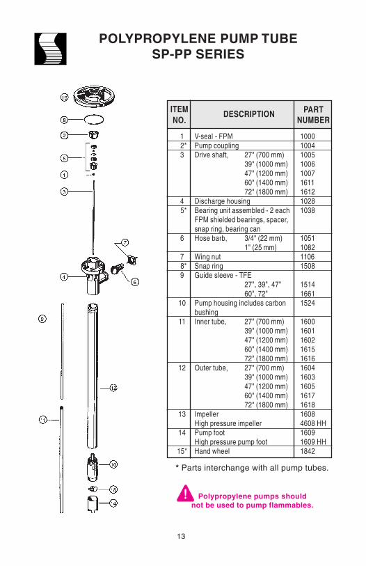
POLYPROPYLENE PUMP TUBESP-PP SERIES
V-seal - FPMPump couplingDrive shaft, 27" (700 mm)
39" (1000 mm)47" (1200 mm)60" (1400 mm)72" (1800 mm)
Discharge housingBearing unit assembled - 2 eachFPM shielded bearings, spacer,snap ring, bearing canHose barb, 3/4" (22 mm)
1" (25 mm)Wing nutSnap ringGuide sleeve - TFE
27", 39", 47"60", 72"
Pump housing includes carbonbushingInner tube, 27" (700 mm)
39" (1000 mm)47" (1200 mm)60" (1400 mm)72" (1800 mm)
Outer tube, 27" (700 mm)39" (1000 mm)47" (1200 mm)60" (1400 mm)72" (1800 mm)
ImpellerHigh pressure impellerPump footHigh pressure pump footHand wheel
PARTNUMBER
DESCRIPTION
100010041005100610071611161210281038
1051108211061508
151416611524
160016011602161516161604160316051617161816084608 HH16091609 HH1842
ITEMNO.
1 2*3
4 5*
6
7 8*9
10
11
12
13
14
15*
Polypropylene pumps shouldnot be used to pump flammables.
* Parts interchange with all pump tubes.
13

14
CPVC PUMP TUBESP-CPVC SERIES
V-seal - TFEPump couplingDrive shaft 27" (700 mm)
39" (1000 mm)47" (1200 mm)60" (1400 mm)72" (1800 mm)
Discharge housingBearing unit assembled - 2 eachFPM shielded bearings, spacer,snap ring, bearing canHose barb, 3/4" (22 mm)
1" (25 mm)Wing nutSnap ringGuide sleeve - TFE
27", 39", 47"60", 72"
Pump housing includes carbonbushingInner tube, 27" (700 mm)
39" (1000 mm)47" (1200 mm)60" (1400 mm)72" (1800 mm)
Outer tube, 27" (700 mm)39" (1000 mm)47" (1200 mm)60" (1400 mm)72" (1800 mm)
ImpellerHigh pressure impellerPump footHigh pressure pump footHand wheel
PARTNUMBER
DESCRIPTION
400010041543154415451546154750281038
5051508251061508
151416615524
560056015602561556165604560356055617561856084608 HH56095609 HH1842
ITEMNO.
1 2*3
4 5*
6
7 8*9
10
11
12
13
14
15*
* Parts interchange with all pump tubes.
CPVC pumps should not be used topump flammables.

15
HIGH TEMPERATURE PUMP TUBESP-PHT SERIES
V-seal - TFEPump couplingDrive shaft 27" (700 mm)
39" (1000 mm)47" (1200 mm)60" (1400 mm)72" (1800 mm)
Discharge housingBearing unit assembled - 2 eachFPM shielded bearings, spacer,snap ring, bearing canHose barb, 3/4" (22 mm)
1" (25 mm)Wing nutSnap ringGuide sleeve - TFE
27", 39", 47"60", 72"
Pump housing includes carbonbushingInner tube, 27" (700 mm)
39" (1000 mm)47" (1200 mm)60" (1400 mm)72" (1800 mm)
Outer tube, 27" (700 mm)39" (1000 mm)47" (1200 mm)60" (1400 mm)72" (1800 mm)
ImpellerHigh pressure impellerPump footHigh pressure pump footHand wheel
PARTNUMBER
DESCRIPTION
4000100415431544154515461547
6028
10386051608261061508
151416616524
660066016602661566166604660366056617661866084608 HH66096609 HH1842
ITEMNO.
1 2*3
4 5*
6
7 8*9
10
11
12
13
14
15*
Polypropylene pumps shouldnot be used to pump flammables.
* Parts interchange with all pump tubes.

16
PVDF PUMP TUBESP-PVDF SERIES
PARTNUMBERDESCRIPTION
Pump couplingDrive shaft 27" (700 mm)
39" (1000 mm) 47" (1200 mm)
Bearing unit assembled - 2 eachFPM shielded bearings, spacer,snap ring, bearing canSnap ringGuide sleeve - TFE
27", 39", 47"Hand wheelV-seal - TFEDischarge housingHose barb, 3/4" (22 mm)
1" (25 mm)Wing nutInner tube, 27" (700 mm)
39" (1000 mm)47" (1200 mm)
Outer tube, 27" (700 mm)39" (1000 mm)47" (1200 mm)
Pump housing includes carbonbushingImpeller - PVDFHigh pressure rotorPump footHigh pressure pump foot
10041543154415451038
1508
15141842400040284051408241064600460146024604460346054607
46084608HH46094609HH
ITEMNO.
1*2
3*
4*5
6*789
1011
12
13
14
15
* Parts interchange with all pump tubes.
PVDF pumps should notbe used to pump flammables.

17
316 STAINLESS STEEL PUMP TUBESP-SS SERIES
PARTNUMBERDESCRIPTION
Pump couplingBearing unit assembled — 2 each
FPM shielded bearings, spacer,snap ring, bearing can
Snap ringHand wheelConnection flangeDrive shaft 27" (700 mm)
39" (1000 mm)47" (1200 mm)60" (1400 mm)72" (1800 mm)
TFE guide sleeve 27" (700 mm) 39" (1000 mm) / 47" (1200 mm)
60" (1400 mm)72" (1800 mm)
Wing nutTFE sealHose barb, 1" (25 mm)Inner/outer tube assembly
27" (700 mm)39" (1000 mm)47" (1200 mm)60" (1400 mm)72" (1800 mm)
Pump housing with carbon bushingTFE impellerHigh pressure impeller'O'-ring, FPM, 2 per setPump footHigh pressure pump footV-Seal - TFE
10041038
150818422000202720282029270927102031203227112712206821952196
27002701270227132714270427064608 HH270727082708 HH4000
* Parts interchange with all pump tubes.
Read and understand operating and safetyinstructions before operating
any Standard Pump.
ITEMNO.
1* 2*
3* 5*67
8
9101112
1314
1516
17

18
AIR MOTORSP-A1
ITEM NUMBER DESCRIPTION
MufflerGasketDead end capBearing (2 req'd)Dead end plateGasket (2 req'd)BodyDrive end plateShaft sealVane (4 req'd)Dowel pin (4 req'd)ImpellerRepair Kit*
Includes item numbers 2, 4,6, 9 and 10.
A1 adapter (not shown)
123456789
10111213
14
PART NUMBER
SAF350SAC229
SAC228ASAG549SAC617SAC527SAE899SAC616
SAC190ASAE893SD324ASAE896
SK285
9007
* Items not sold separately. Item sold as part of repair kit, item 13.
Read and understand operating and safety instructions beforeoperating any Standard Pump.

19
PART NUMBER
Motor housingTrigger assembly repair kit (includes items 2-8)
TriggerThrottle valve assemblyThrottle valve sealThrottle valve springThrottle valve body assemblyValve body sealValve body sealValve body retaining pin
Speed regulator repair kit (includes items 9-12)
Speed regulator assemblyRegulator seal (2 req'd)Regulator retainerInlet bushing
Rear impeller bearingRear impeller repair kit (includes items 14 & 14A)
Rear end plate assemblyDowel (end plate)
Cylinder repair kit (includes items 15 & 16)
Cylinder assemblyDowel (cylinder)
ImpellerVane packet (4)Impeller spacerFront end plateFront impeller bearingMotor locknutMuffler (not shown)Motor coupling (not shown)A2 adapter (not shown)
ITEM NUMBER
1
23456
6A78
910111213
1414A
1516171819202122232425
DESCRIPTION
AIR MOTORSP-A2
NOTE: Part Numbers 8333 and 9014 are not shown
Read and understand operating and safety instructions beforeoperating any Standard Pump.
S317-40S317-00
S317-93S317-A302
S317-103S317-51
S317-A503S7802-291S7802-291
S317-120S317-01
S317-A249S310-169S317-118S317-38S222-22S317-02
S317-A12S308-98S317-03
S317-A3S308-98S317-53
S317-42-4S317-65S317-11S317-22S317-27SAF350
83339014

20
*Parts interchange with all Standard electric motors
SP-280P open motor shouldnot be used to pump flammables.
PARTNUMBERDESCRIPTION
Motor coverSwitch housingSwitch housing for variablespeed includes potentiometer
115V220V
Switch housing for batch controlincludes potentiometer andBCS port connection 115V
220VSwitch coverLock washerLower housingWave washerBall bearingScrew for plastic housingScrewGround screwGasket low voltage release (for 220V)Earthing leadLeadScrewBall bearingMotor couplingPower cord w/strain relief & plug
115V220V
Hexagon nutArmature 115V
220VStator 115V
220VGuide discRod connectorPressure springBrush holderCarbon brush 115V
220VMotor housing, plasticStar washerFanOverload switch, 8.5 amp 115V 5 amp 220V low voltage release
80008001
80048005
80068007800280718100812581268130P8131816281678167LVR81838185822083318333
83608705844885028701850387028504850685078508850987038510P85118512
86118704LVR
ITEMNO. 1 2* 2A*
2B*
3* 4* 5* 6* 7 8 9*10*11*
1213*14*1516*17*
18*19
20
21222324*25*
26272829*
OPEN DRIP PROOF MOTORSP-280P SERIES

21
OPEN DRIP PROOF MOTORSP-ODP SERIES
PARTNUMBERDESCRIPTION
Motor assemblyOverload switch 8.5 amp, 115V
5 amp, 220VMotor couplingCase rightActuator switch (2 req'd.)Pin rocker switchCase leftScrew #8 x ½ L pan head
Plastite (7 req'd.)Power cord w/strain 115Vrelief & plug 220V
89008611
8704 LVR83338901890389048902
890583618706
ITEMNO.
12*
3*45678
9
SP-ODP open motor shouldnot be used to pump flammables.
8 4
16
2
5
7
9
*Parts interchange with all Standard electric motors

22
TEFC MOTORSP-ENC SERIES
PARTNUMBERDESCRIPTION
Motor coverScrewArmature 115V
220VStator 115V
220VGuide discMotor housingBearing coverFanSwitch housingSwitch housing for variable speedincludes potentiometer 115V
220VSwitch housing for batch controlincludes potentiometer andBCS port connection 115V
220VSwitch coverLock washerLower housingWave washerBall bearingScrewScrewGround screwGasket
Low voltage release (for 220V)Earthing leadLeadScrewBall bearingMotor couplingPower cord w/strain relief & plug
115V220V
Hexagon nutRod connectorBrush holderCarbon brush, 115V
220VStar washerOverload switch, 8.5 amp 115V 5 amp 220V low voltage release
30003130350237013503370235043510351135128001
80048005
800680078002807181008125812681308131816281678167LVR81838185822083318333
83608705844837038508850987038511
86118704LVR
ITEMNO. 1 2 3
4
5 6 7 8 9* 9A*
9B*
10*11*12*13*14*1516*17*18*
192021*2223*24*
25*2627*28*
29*30*
SP-ENC motor should notbe used to pump flammables.
*Parts interchange with all Standard electric motors

23
EXPLOSION-PROOF MOTORSP-400-2 SERIES
PARTNUMBERDESCRIPTION
Fan coverBearing coverWave washer (2 req'd)Glass sleeveMotor housingLower housingMotor couplingStator 230VArmature 230VSwitch housingGround connectorSet screwCord without plugStrain reliefHandleCord clampPass through (4 req'd)SwitchOn / Off knobConnector terminalFanSwitch handle screw (4 req'd)Switch housing screw (4 req'd)Motor bolt nut (8 req'd)Switch housing washer (4 req'd)Motor bolt washer (8 req'd)Brush holderRod connector (2 req'd)Ball bearing (2 req'd)Carbon brush 220V (2 req'd)Switch bracketSwitch actuatorSwitch bracket screw (2 req'd)Switch actuator pinBrush tab screw (2 req'd)Brush tab (2 req'd)Fan cover screw (4 req'd)Fan cover screw washer (4 req'd)Motor bolt (4 req'd)
50135004505051375007500683333702500150088183-250288705-EXP5046-15005501050368704LVR5017????50205045504450435049-035049-0285085015-0450538703501150095015-0150168508-18508-25015-025049-015018-01
ITEMNO. 1 2 3 4 5 6 7 8 9101112131415161718192021222324252627282930313233343536373839
18
21
2019
17
16
15
13
14
12
1011
12
4
5
7
69
8
3
22
23
2426
27
25
28
29
BACK(HANDLE)
VIEW
FRONTVIEW
TOP VIEW
3130
32
36 3534 33
38
37
39

24
SECTION 6:
TRANSFERRING OF FLAMMABLES OR USE INHAZARDOUS DUTY ENVIRONMENTS
Bonding is an electrical connection between a primary metal vessel and ametal receiving vessel. See schematic.
Grounding is an electrical connection between a metal vessel, pump,motor and a constant ground; i.e. a metal rod driven into the earth.
Bonding and grounding are required when pumping flammable materialsor in hazardous duty environments. Failure to bond and ground properly can causea discharge of static electricity resulting in fire, injury or death. Follow NFPA 77and 30 procedures at all times. If in doubt, do not start pump! Be sure bondingand grounding wires are secure before starting operation. (Ground and bondwires must have less than one ohm resistance for safe usage. Check continuitybefore starting.) Always check with a safety engineer when any question arisesand periodically check safety procedures with a safety engineer.
Groundwire
Rod
No splashing
Metaldrum
Optionals:Solvent resistant safetyhose with wire ground
Motor: Explosion-ProofPump Tube: SP-SS
Metaldrum
Bondwire
Optionals:Solvent resistantsafety hosewith wire ground
Air Motor: SP-A1 or SP-A2Pump Tube: SP-SS
Groundwire
MufflerAir line
Earth ground
RodMetaldrum
Nosplashing
Metaldrum
Bondwire
Earth ground

25
Declarations
Declaration of Conformity When this unit is used as a stand alone unit itcomplies with:
Machinery Directive 98/37/EC EN60204,EN60335-2-41, EN60335-1,
Low Voltage Directive 73/23/Eec EN61010-1,EMC Directive 89/336/Eec EN55014, EN 550104,EN50081-1, EN50082-1
Declaration of Incorporation When this pump unit is to be installed into machineor is to be assembled with other machines forinstallations, it must not be put into service untilthe relevant machinery has been declared inconformity with Machine Directive 98/37/ECEN60204, EN60335-2-41, EN60335-1.
Responsible person: Donald M. Murphy, Managing Director, Standard Pump, Inc.,
Three year warranty
Standard Pump, Inc. warrants, subject to the conditions below, through either StandardPump, Inc., it’s subsidiaries, or its authorized distributors, to repair or replace free ofcharge, including labor, any part of this equipment which fails within three years of deliveryof the product to the end user. Such failure must have occurred because of defect inmaterial or workmanship and not as a result of operation of the equipment other than inaccordance with the instructions given in this material. Specific exceptions include:
● consumable items such as motor brushes, bearings, couplings and impellers.
Conditions of exceptions include:● Equipment must be returned by prepaid carriage to Standard Pump, Inc.,
its subsidiary or authorized distributor.● All repairs, modifications must have been made by or with express written
permission by Standard Pump, Inc., it’s subsidiary or authorized distributor.● Equipment which have been abused, misused, or subject to malicious or
accidental damage or electrical surge are excluded.
Warranties purporting to be on behalf of Standard Pump, Inc. made by any person, includingrepresentatives of Standard Pump, Inc, its subsidiaries, or its distributors, which do notfall within the terms of this warranty shall not be binding upon Standard Pump, Inc. unlessexpressly approved in writing by a Director or Manager of Standard Pump, Inc.
Information for returning pumps
Equipment which has been contaminated with, or exposed to, bodily fluids, toxic chemicalsor any other substance hazardous to health must be decontaminated before it is returnedto Standard Pump, Inc, or its distributor.
A returned goods authorization number (RGA #) issued by Standard Pump, Inc., its subsidiaryor authorized distributor, must be included with the returned equipment. The RGA # isrequired if the equipment has been used. If the equipment has been used, the fluidsthat have been in contact with the pump and the cleaning procedure must be specifiedalong with a statement that the equipment has been decontaminated.

26
NOTES

27
NOTES

28