dry metal forming open access journalmetal forming processes without conventional lubricants shorten...
TRANSCRIPT
Edited by Frank Vollertsen Available online at elib.suub.uni-bremen.de www.drymetalforming.de
Dry Met. Forming OAJ FMT 4 (2018) 035–046 Received January 12, 2018; published February 13, 2018
© 2018 The Authors. Selection under responsibility of BIAS - Bremer Institut für angewandte Strahltechnik GmbH. *E-mail address of corresponding author: [email protected]
Dry Metal Forming Open Access Journal
Fast Manuscript Track
Influence of laser generated micro textured coated tool surfaces on
dry deep drawing processes
Jennifer Tenner1*, Tom Häfner2, Benedict Rothammer3, Kim Krachenfels1, Rong Zhao3, MichaelSchmidt2, Stephan Tremmel3, Marion Merklein1
1Institute of Manufacturing Technology, Friedrich-Alexander-Universität Erlangen-Nürnberg (FAU), Egerlandstr. 13, 91058 Erlangen, Germany 2Institute of Photonic Technologies, Friedrich-Alexander-Universität Erlangen-Nürnberg (FAU), Konrad-Zuse-Str. 3/5, 91052 Erlangen, Germany 3Institute of Engineering Design, Friedrich-Alexander-Universität Erlangen-Nürnberg (FAU), Martensstr. 9, 91058 Erlangen, Germany
Abstract
The idea of sustainability and resource conservation promotes the development of energy-efficient and low-emission production processes. A lubricant-free sheet metal forming process is considered as one of these environmentally friendly production technologies. Metal forming processes without conventional lubricants shorten process steps and reduce additional costs, such as removal of residual lubrication from the workpiece after forming. In order to realize such a dry forming process and effectively control the material flow, amorphous carbon coatings were applied to the tool surfaces and a brushing process was carried out as a surface finishing process for roughness adjustment. Laser generated micro features on the surface should make an effective contribution to local friction adaptation. The transferability of strip drawing test to strip bending rotation test was successfully demonstrated by dry and oiled blank reference tests. The first modification of the tool sided surface was achieved by applying ta-C and a-C:H layers. The influence of the coatings on the tribological behaviour was determined in strip drawing tests for DC04 and AA5182. Additional friction adaptation is made possible by the fine and flexible laser based micro texturing of the coated tool surface. Experiments were carried out with different coverage and depth of the laser generated features in order to analyze the tribological influence. Flat and deep features with a degree of coverage of 20 %, 35 % and 50 % are considered in order to analyze the factors influencing their tribological behavior. Compared to ta-C coated references, it can be seen that micro features on the ta-C coated tool surface causes a friction reduction for DC04, independent of the features depth. However, deep laser generated features in particular lead to an increase in friction for AA5182, so that this could potentially lead to a selective local increase in friction in the flange area. For the transferability of the tribological system from the flat application case to a curved tool surface, the basics for laser based texturing of cylinder surfaces are illustrated. The limits of the holographic beam shaping technology used for this are demonstrated.
Keywords: Dry Deep Drawing, Tribology, Carbon Based Coatings, Laser Based Texturing
1 Introduction and methodology
Dry sheet metal forming is primarily promoted by ecological and economical aspects [1]. The absence of lubricants leads to higher friction and substantial wear. As part of the DFG SPP1676 priority program ‘Dry metal forming’ this project faces the challenges in dry deep drawing process by the concept of a tailored tool with locally adapted friction conditions. Different types of surface modifications are investigated in order to create tailored tribological systems for dry deep drawing. Dry deep drawing tests carried out previously showed that particularly the radius area is subject to high tribological stress. Therefore, it is important to tribologically analyze this area in laboratory tests. For
this reason, a strip bending rotation test was developed. In order to demonstrate its suitability, the results of strip bending rotation tests were compared with previous studies on lubricated and dry strip drawing tests. First of all, the transferability of the general tribological behavior and influencing factors of strip drawing test to strip bending rotation test by means of dry and lubricated reference tests is shown. The first modification of the tool sided surface was achieved by the application of tribologically effective tetrahedral amorphous (ta-C) and hydrogenated amorphous carbon based (a-C:H) coatings. The influence of the coatings on the tribological behavior was determined in strip drawing tests for DC04 and AA5182. An additional
35
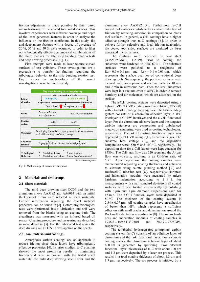
friction adjustment is made possible by laser based micro texturing of the coated tool sided surfaces. This involves experiments with different coverage and depth of the laser generated features in order to analyze the influence on the friction coefficient. In this study, flat and deep micro features with a degree of coverage of 20 %, 35 % and 50 % were examined in order to filter out tribologically effective geometrical combinations of the micro features for later strip bending rotation tests and deep drawing processes (Fig. 1).
First attempts were made to laser texture curved surfaces of test cylinders. These investigations are a prerequisite to transfer the findings regarding the tribological behavior to the strip bending rotation test. Fig. 1 shows the methodology of the current investigations presented in this study.
Fig. 1: Methodology of current investigation
2 Materials and test setups
2.1 Sheet materials
The mild deep drawing steel DC04 and the two aluminum alloys AA5182 and AA6014 with an initial thickness of 1 mm were selected as sheet materials. Further information regarding the sheet material properties can be found in [2]. Before any tribological tests were performed, basic lubrication and soil were removed from the blanks using an acetone bath. The cleanliness was measured with an infrared based oil sensor. Cleaning procedure and measuring are described in more detail in [3]. For the lubricated test series the deep drawing oil KTL N 16 was applied on the sheets
2.2 Tool material and coatings
Amorphous carbon coatings are an approach to reduce friction since these layers have tribologically effective properties [4]. In prior studies, ta-C coatings showed the most promising results in minimizing friction and wear in contact with the tested sheet materials: the mild deep drawing steel DC04 and the
aluminum alloy AA5182 [ 5 ]. Furthermore, a-C:H coated tool surfaces contribute to a certain reduction of friction by reducing adhesion in comparison to blank tool surfaces. In general, a-C:H coatings have a higher adhesive strength than ta-C coatings [6]. In order to achieve further selective and local friction adaptation, the coated tool sided surfaces are modified by laser generated micro features.
The coatings were deposited on tool steel (X155CrVMo12, 1.2379). Prior to coating, the substrates were hardened to HRC 60 ± 1. The substrate surfaces were polished to a roughness of Rz = 0.9 ± 0.1 µm and Rpk = 0.1 ± 0.01 µm, which represents the surface qualities of conventional deep drawing tools. Subsequently, the polished surfaces were cleaned with isopropanol and acetone each for 10 min and 2 min in ultrasonic bath. Then the steel substrates were kept in a vacuum oven at 80°C, in order to remove humidity and air molecules, which are adsorbed on the surface.
The a-C:H coating systems were deposited using a hybrid PVD/PECVD coating machine (H-O-T, TT-300) with a twofold rotating charging rack. The basic coating system consists of a chromium adhesive layer, a WC interlayer, a-C:H:W interlayer and the a-C:H functional layer. For the chromium adhesive layer and the tungsten carbide interlayer arc evaporation and unbalanced magnetron sputtering were used as coating technologies, respectively. The a-C:H coating functional layer was deposited by PECVD using C2H2 as precursor gas. The substrate bias voltage Ubias and the deposition temperature were -550 V and 100 °C, respectively. The deposition time for a-C:H layers were kept constant for 8580 s. The C2H2 gas flow was 220 sccm and the Ar gas flow was 40 sccm, resulting in an C2H2/Ar ratio of 5.5:1. After deposition, the coating samples were characterized regarding coating thickness and adhesion to substrate using calotte grinding method [ 7 ] and Rockwell C adhesion test [8 ], respectively. Hardness and indentation modulus were measured by micro hardness indentation according to [ 9 ]. For measurements with small standard deviations all coated surfaces were post treated mechanically by polishing with 3 µm and 1 µm diamond suspensions each for 15 min. The a-C:H function layers were deposited at 80 °C. The thickness of the coating system is 2.34 ± 0.07 µm. All coating samples have an adhesion of better than HF4, which represents a sufficient adhesion with small cracks and delamination around the Rockwell indentation according to [8]. The micro hard-ness and indentation modulus of coating samples is 1936.8 ± 109.5 HV 0.001 and 502.7 ± 28.9 GPa, respectively.
The tetrahedral hydrogen-free amorphous carbon coating system (ta-C) consists of an adhesive layer of chromium and the ta-C functional layer. For a smooth coating surface the chromium adhesive layer of about 600 nm is generated by sputtering. Two different functional layer thicknesses of ta-C with about 700 nm and 1.3 µm were deposited by a laser arc process. This results in a total coating thickness of about 1.3 µm and 1.9 µm, respectively. The arc process is initiated by a
Tenner et al. / Dry Metal Forming OAJ FMT 4 (2018) 35-46 36

laser pulse on the carbon (graphite) target [10]. In order to ensure a smooth coating, a magnetic field is used to filter the macro particles from the arc process. After the deposition the coated samples are mechanically treated by polishing and brushing with diamond paste with a grain size of 3 µm. All coating samples have an adhesion of better than HF4. The micro hardness and indentation modulus of coating samples is 5017.9 ± 1164.0 HV 0.002 and 330.6 ± 52.4 GPa, respectively. In order to reduce the roughness of the ta-C and a-C:H coatings on the friction jaws after the deposition process, the mechanical surface finishing of the brush was used [11 ]. For ta-C the roughness is Rz = 0.26 ± 0.01 µm and Rpk= 0.045 ± 0.005 µm and for a-C:H the roughness is Rz = 0.59 ± 0.07 µm and Rpk= 0.05 ± 0.009 µm. Rpk provides the target value to reduce wear-induced mechanisms such as abrasion. Therefore, the influence of the different Rz values can be subordinated.
2.3 Setup of flat strip drawing test
Flat strip drawing tests were selected to determine friction coefficients in an environment closer to real forming processes than in tribometer tests. The flat strip drawing test (Fig. 2) models the tribological conditions of the flange area of a deep drawing process. A sheet metal strip is located between an upper fixed and a lower movable friction jaw which applies a defined normal force. Within this study, the contact pressure was varied between 4.5 MPa for DC04 and 1.5 MPa for AA5182 and AA6014. Under real forming conditions the pressure in the flange area is selected in a range from 1 up to 10 MPa [12]. In all flat strip drawing tests the drawing velocity was set to 100 mm/s which is a typical velocity for deep drawing processes. During drawing of the strip the necessary drawing force is recorded. By applying the Coulomb friction law the friction coefficient µflat is determined as relation of drawing force to normal force. The friction jaws measure 100 x 55 mm. To ensure that the cutting edge is not in contact with the tools, the sheet metal strips have a width of 65 mm.
Fig. 2: Principle of flat strip drawing test
2.4 Setup of strip bending rotation test
Former numerical and experimental investigations revealed high tribological loads at the tool radii during dry deep drawing. In order to analyze this critical areas a further test setup was developed, which models the
friction conditions along the die radius. The basic principle of the strip bending rotation test is shown in Fig. 3. In a first step a sheet metal strip is located between a die and a test cylinder. The test cylinder moves downwards to apply the bending force FB which enables a two-sided contact of the strip with the tools. Then the sheet metal strip is clamped on both sides. It is possible to apply a preloading force FPL to achieve a prestraining of the strip. After clamping of the sheet metal strip, the test cylinder applies the defined normal force FN. Then the test cylinder is rotated with a defined relative velocity vrel. The torsional moment MT which is necessary to rotate the test cylinder is measured during the tests. By applying the Coulomb friction law the friction coefficient µbend is determined by MT/(FN ∙ r).
Fig. 3: Principle of strip bending rotation test
In comparison to commonly known strip drawing tests with redirection, this test setup enables higher contact pressure without failure of the strips, an easier separation of bending and friction forces and a homogenous contact pressure, which is necessary to analyze the influence of varying pressures on the tribological conditions. Compared to tribometer tests like the ring-on-disc setup an open tribological system is realized by restriction of the rotation angle to 90°. For the tests within this study the test cylinders have a radius of 15 mm, the die has a radius of 16 mm and a width of 26 mm. As well as in the flat strip drawing tests the strips are wider than the tool to avoid the cutting edge being in contact. According to [13] the contact pressure is determined using the projected pressurized contact surface Aps. Within this investigation a contact pressure of 22 MPa was defined for DC04 and a pressure of 12 MPa for AA6014 and AA5182. These levels of contact pressure match the lower boundary of contact pressures along the die radius according to numerical simulations. The velocity was set constant to 36 mm/s which equals the upper limit of the deployed devices.
3 Results and discussion
3.1 Tribological behavior of flat and bended strips
under dry conditions
In a first step, basic investigations about the tribological behavior in the two different test setups described in section 2.3 and 2.4 were conducted to analyze the transferability of the results. A comparison
Tenner et al. / Dry Metal Forming OAJ FMT 4 (2018) 35-46 37
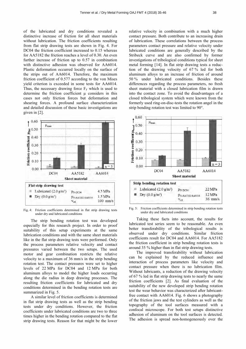
of the lubricated and dry conditions revealed a distinctive increase of friction for all sheet materials without lubrication. The friction coefficients resulting from flat strip drawing tests are shown in Fig. 4. For DC04 the friction coefficient increased to 0.15 whereas for AA5182 the friction reaches a level of 0.30. An even further increase of friction up to 0.57 in combination with distinctive adhesion was observed for AA6014. Plastic deformation occurred locally on the surface of the strips out of AA6014. Therefore, the maximum friction coefficient of 0.577 according to the von Mises yield criterion is exceeded in some tests for AA6014. Thus, the necessary drawing force FF which is used to determine the friction coefficient µ considers in this cases not only friction forces but deformation and shearing forces. A profound surface characterization and detailed discussion of these basic investigations are given in [2].
Fig. 4: Friction coefficients determined in flat strip drawing tests
under dry and lubricated conditions
The strip bending rotation test was developed especially for this research project. In order to proof suitability of this setup experiments at the same lubrication conditions and with the same sheet materials like in the flat strip drawing tests were performed. Only the process parameters relative velocity and contact pressures varied between the two setups. The used motor and gear combination restricts the relative velocity to a maximum of 36 mm/s in the strip bending rotation test. The contact pressures were set to higher levels of 22 MPa for DC04 and 12 MPa for both aluminum alloys to model the higher loads occurring along the die radius in deep drawing processes. The resulting friction coefficients for lubricated and dry conditions determined in the bending rotation tests are summarized in Fig. 5.
A similar level of friction coefficients is determined in flat strip drawing tests as well as the strip bending tests under dry conditions. However, the friction coefficients under lubricated conditions are two to three times higher in the bending rotation compared to the flat strip drawing tests. Reason for that might be the lower
relative velocity in combination with a much higher contact pressure. Both contribute to an increasing drain of lubrication. These correlations between the process parameters contact pressure and relative velocity under lubricated conditions are generally described by the Stribeck curve and are also confirmed by former investigations of tribological conditions typical for sheet metal forming [14]. In flat strip drawing tests a reduc-tion of the drawing velocity of 67 % led for both aluminum alloys to an increase of friction of around 50 % under lubricated conditions. Besides these differences regarding the process parameters, no fresh sheet material with a closed lubrication film is drawn into the contact zone. To avoid the disadvantages of a closed tribological system which were known from the formerly used ring-on-disc-tests the rotation angel in the strip bending rotation test was limited to 90°.
Fig. 5: Friction coefficients determined in strip bending rotation tests
under dry and lubricated conditions
Taking these facts into account, the results for lubricated test series seem to be reasonable. An even better transferability of the tribological results is observed under dry conditions. Similar friction coefficients result for DC04 and AA6014. For AA5182 the friction coefficient in strip bending rotation tests is around 35 % higher than in flat strip drawing tests.
The improved transferability without lubrication can be explained by the reduced influence and interaction of process parameters like velocity and contact pressure when there is no lubrication film. Without lubricants, a reduction of the drawing velocity of 67 % led in flat strip drawing tests to nearly the same friction coefficients [2]. As final evaluation of the suitability of the new developed strip bending rotation test the wear behavior was characterized after lubricant-free contact with AA6014. Fig. 6 shows a photography of the friction jaws and the test cylinders as well as the topography of the tool surfaces measured with a confocal microscope. For both test setups distinctive adhesion of aluminum on the tool surfaces is detected. The adhesion is spread non-homogeneously over the
Tenner et al. / Dry Metal Forming OAJ FMT 4 (2018) 35-46 38
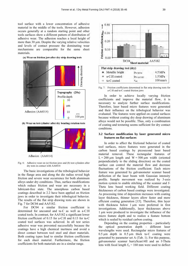
tool surface with a lower concentration of adhesive material in the middle of the tools. However, adhesion occurs generally at a random starting point and other tools surfaces show a different pattern of distribution of adhesive wear. The adhesion reaches a local height of more than 30 µm. Despite the varying relative velocities and levels of contact pressure the dominating wear mechanisms are comparable for the same sheet materials.
Fig. 6: Adhesive wear on (a) friction jaws and (b) test cylinders after
dry tests in contact with AA6014
The basic investigations of the tribological behavior in the flange area and along the die radius reveal high friction and severe wear occurrence for both aluminum alloys under dry conditions. Thus, surface modifications which reduce friction and wear are necessary in a lubricant-free state. The amorphous carbon based coatings described in 2.2 have been applied on friction jaws in order to investigate their tribological behavior. The results of the flat strip drawing tests are shown in Fig. 7 for DC04 and AA5182.
For DC04 a similar friction coefficient is determined for uncoated and ta-C as well as a-C:H coated tools. In contrast, for AA5182 a significant lower friction coefficient of 0.15 for a-C:H and 0.13 for ta-C coated tool surfaces was achieved. In all test series adhesive wear was prevented successfully because the coatings have a high chemical inertness and avoid a direct contact between tool steel and sheet materials. Both coating types lead to similar friction coefficients for each sheet material. Furthermore, the friction coefficients for both materials are in a similar range.
Fig. 7: Friction coefficients determined in flat strip drawing tests for
a-C:H and ta-C coated friction jaws
In order to achieve locally varying friction coefficients and improve the material flow, it is necessary to analyze further surface modifications. Therefore, laser based micro features were generated and their influence on the tribological behavior was evaluated. The features were applied on coated surfaces because without coating dry deep drawing of aluminum alloys would not be possible. Thus, only a combination of coating and texturing seems sufficient for dry contact conditions.
3.2 Surface modification by laser generated micro
features on flat surfaces
In order to affect the frictional behavior of coated tool surfaces, micro features were generated in the carbon based coatings by picosecond laser based material removal. These rectangular features of L = 200 µm length and W = 500 µm width (oriented perpendicularly to the sliding direction) on the coated surface can control the material flow and decrease fluctuations of the friction coefficient. Each micro feature was generated by galvanometer scanner based deflection of the laser beam with Gaussian intensity profile. Sample movement was realized by 3-axis motion system to enable stitching of the scanner and f-Theta lens based working field. Different coating thicknesses of carbon based coatings were investigated. As processing time of deposition increases with coating layer thickness, thinner layers allow faster and more efficient coating generation [15]. Therefore, thin layer with thickness below 1 µm were preferred in first investigations. Additionally, layer thicknesses above 1 µm were produced to investigate the influence of the micro feature depth and to realize a feature bottom which is sealed by residual carbon coating.
Depending on the coating properties - particularly the optical penetration depth - different laser wavelengths were used. Rectangular micro features of 0.5 µm depth in 0.5 µm thick ta-C coating were generated by parameter set A (Tab. 1). For this purpose, galvanometer scanner hurryScan14II and an f-Theta lens with focal length fA = 160 mm were used to deflect
Tenner et al. / Dry Metal Forming OAJ FMT 4 (2018) 35-46 39
the laser focal spot with spot diameter (1/e²) dA = 31 µm. Applying λA = 1064 nm the complete ta-C coating thickness was locally removed, so that the adhesive chromium layer is exposed at the feature bottom [ 16 ]. Texturing of ta-C coatings with layer thickness of about 1.3 µm was carried out with λB = 355 nm (step B, Tab. 1). The choice of this wavelength is motivated by the bandgap of 2.6 eV (≙ 477 nm) and optical penetration depth of this coating type [17]. The optical penetration depth at 355 nm is much smaller than the coating thickness. Thus, this wavelength is absorbed within the coating layer enabling the generation of a certain feature depth lower than the layer thickness [18], so the feature bottom is still covered by the residual carbon based coating. Tab. 1: Parameter settings of laser texturing steps for micro feature
generation in ta-C and a-C:H coatings. The pulse frequency for each set was 50 kHz and the hatch distance of parallel scanning lines py = 6.0 µm (except of step A: py = 10.0 µm).
Coa-ting
Step Wave-length λ in nm
Peak fluence F0 in J/cm²
Spot size d in µm
Scan speed vS in mm/s
No. of passes
N
Depth t in µm
ta-C A 1064 0.6 31 350 1 0.5
B.1 355 1.3 26 200 2 0.5 B.2 355 1.5 26 200 1 0.9
a-C:H C 1064 1.9 24 250 1 0.5
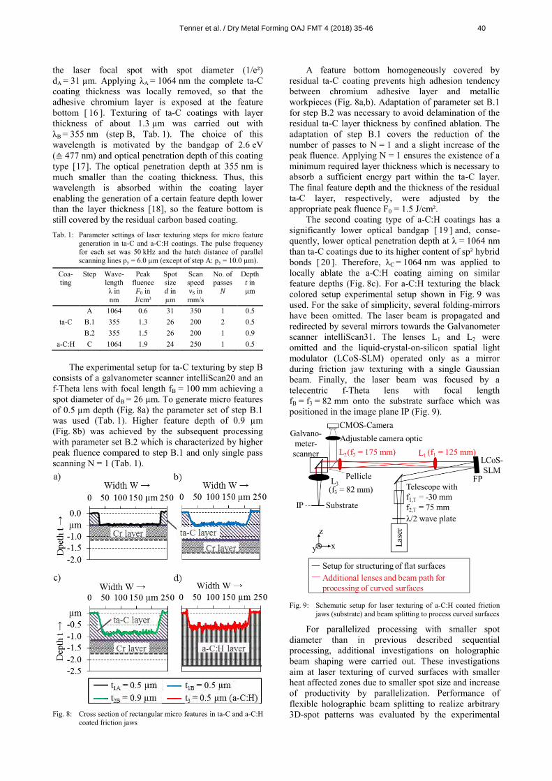
The experimental setup for ta-C texturing by step B consists of a galvanometer scanner intelliScan20 and an f-Theta lens with focal length fB = 100 mm achieving a spot diameter of dB = 26 µm. To generate micro features of 0.5 µm depth (Fig. 8a) the parameter set of step B.1 was used (Tab. 1). Higher feature depth of 0.9 µm (Fig. 8b) was achieved by the subsequent processing with parameter set B.2 which is characterized by higher peak fluence compared to step B.1 and only single pass scanning N = 1 (Tab. 1).
Fig. 8: Cross section of rectangular micro features in ta-C and a-C:H
coated friction jaws
A feature bottom homogeneously covered by residual ta-C coating prevents high adhesion tendency between chromium adhesive layer and metallic workpieces (Fig. 8a,b). Adaptation of parameter set B.1 for step B.2 was necessary to avoid delamination of the residual ta-C layer thickness by confined ablation. The adaptation of step B.1 covers the reduction of the number of passes to N = 1 and a slight increase of the peak fluence. Applying N = 1 ensures the existence of a minimum required layer thickness which is necessary to absorb a sufficient energy part within the ta-C layer. The final feature depth and the thickness of the residual ta-C layer, respectively, were adjusted by the appropriate peak fluence F0 = 1.5 J/cm².
The second coating type of a-C:H coatings has a significantly lower optical bandgap [ 19 ] and, conse-quently, lower optical penetration depth at λ = 1064 nm than ta-C coatings due to its higher content of sp² hybrid bonds [ 20 ]. Therefore, λC = 1064 nm was applied to locally ablate the a-C:H coating aiming on similar feature depths (Fig. 8c). For a-C:H texturing the black colored setup experimental setup shown in Fig. 9 was used. For the sake of simplicity, several folding-mirrors have been omitted. The laser beam is propagated and redirected by several mirrors towards the Galvanometer scanner intelliScan31. The lenses L1 and L2 were omitted and the liquid-crystal-on-silicon spatial light modulator (LCoS-SLM) operated only as a mirror during friction jaw texturing with a single Gaussian beam. Finally, the laser beam was focused by a telecentric f-Theta lens with focal length fB = f3 = 82 mm onto the substrate surface which was positioned in the image plane IP (Fig. 9).
Fig. 9: Schematic setup for laser texturing of a-C:H coated friction
jaws (substrate) and beam splitting to process curved surfaces
For parallelized processing with smaller spot diameter than in previous described sequential processing, additional investigations on holographic beam shaping were carried out. These investigations aim at laser texturing of curved surfaces with smaller heat affected zones due to smaller spot size and increase of productivity by parallelization. Performance of flexible holographic beam splitting to realize arbitrary 3D-spot patterns was evaluated by the experimental
Tenner et al. / Dry Metal Forming OAJ FMT 4 (2018) 35-46 40
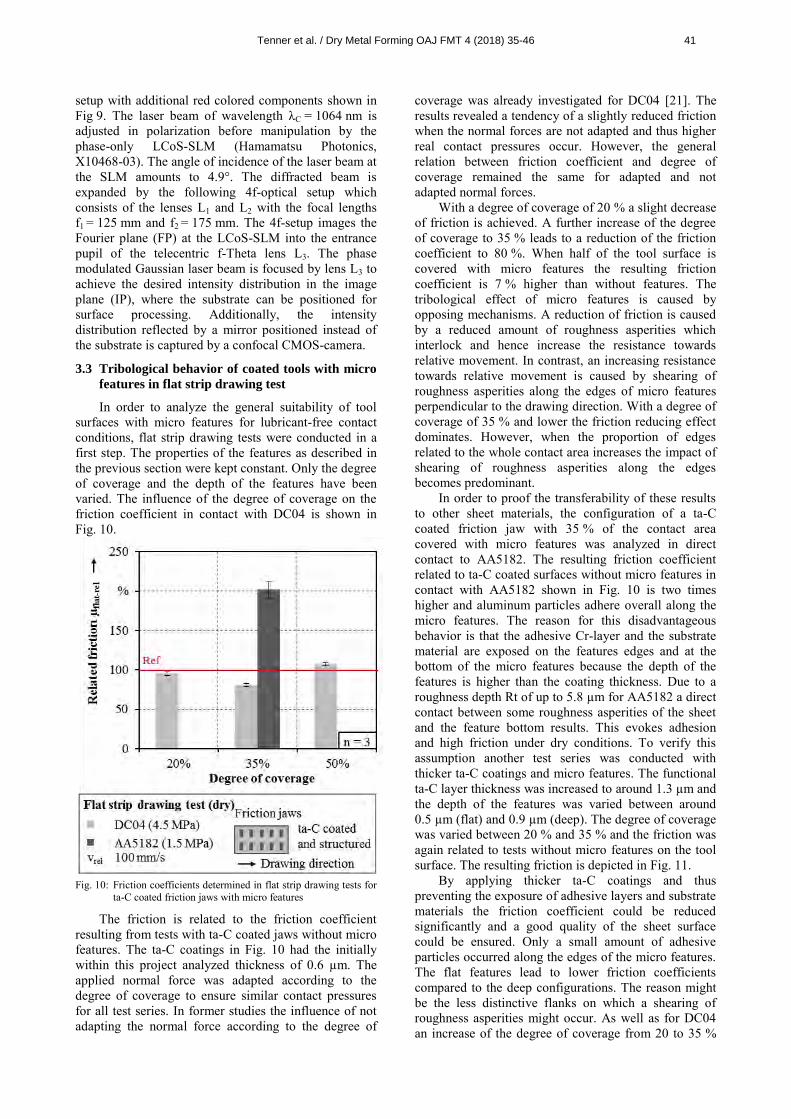
setup with additional red colored components shown in Fig 9. The laser beam of wavelength λC = 1064 nm is adjusted in polarization before manipulation by the phase-only LCoS-SLM (Hamamatsu Photonics, X10468-03). The angle of incidence of the laser beam at the SLM amounts to 4.9°. The diffracted beam is expanded by the following 4f-optical setup which consists of the lenses L1 and L2 with the focal lengths f1 = 125 mm and f2 = 175 mm. The 4f-setup images the Fourier plane (FP) at the LCoS-SLM into the entrance pupil of the telecentric f-Theta lens L3. The phase modulated Gaussian laser beam is focused by lens L3 to achieve the desired intensity distribution in the image plane (IP), where the substrate can be positioned for surface processing. Additionally, the intensity distribution reflected by a mirror positioned instead of the substrate is captured by a confocal CMOS-camera.
3.3 Tribological behavior of coated tools with micro
features in flat strip drawing test
In order to analyze the general suitability of tool surfaces with micro features for lubricant-free contact conditions, flat strip drawing tests were conducted in a first step. The properties of the features as described in the previous section were kept constant. Only the degree of coverage and the depth of the features have been varied. The influence of the degree of coverage on the friction coefficient in contact with DC04 is shown in Fig. 10.
Fig. 10: Friction coefficients determined in flat strip drawing tests for
ta-C coated friction jaws with micro features
The friction is related to the friction coefficient resulting from tests with ta-C coated jaws without micro features. The ta-C coatings in Fig. 10 had the initially within this project analyzed thickness of 0.6 µm. The applied normal force was adapted according to the degree of coverage to ensure similar contact pressures for all test series. In former studies the influence of not adapting the normal force according to the degree of
coverage was already investigated for DC04 [21]. The results revealed a tendency of a slightly reduced friction when the normal forces are not adapted and thus higher real contact pressures occur. However, the general relation between friction coefficient and degree of coverage remained the same for adapted and not adapted normal forces.
With a degree of coverage of 20 % a slight decrease of friction is achieved. A further increase of the degree of coverage to 35 % leads to a reduction of the friction coefficient to 80 %. When half of the tool surface is covered with micro features the resulting friction coefficient is 7 % higher than without features. The tribological effect of micro features is caused by opposing mechanisms. A reduction of friction is caused by a reduced amount of roughness asperities which interlock and hence increase the resistance towards relative movement. In contrast, an increasing resistance towards relative movement is caused by shearing of roughness asperities along the edges of micro features perpendicular to the drawing direction. With a degree of coverage of 35 % and lower the friction reducing effect dominates. However, when the proportion of edges related to the whole contact area increases the impact of shearing of roughness asperities along the edges becomes predominant.
In order to proof the transferability of these results to other sheet materials, the configuration of a ta-C coated friction jaw with 35 % of the contact area covered with micro features was analyzed in direct contact to AA5182. The resulting friction coefficient related to ta-C coated surfaces without micro features in contact with AA5182 shown in Fig. 10 is two times higher and aluminum particles adhere overall along the micro features. The reason for this disadvantageous behavior is that the adhesive Cr-layer and the substrate material are exposed on the features edges and at the bottom of the micro features because the depth of the features is higher than the coating thickness. Due to a roughness depth Rt of up to 5.8 µm for AA5182 a direct contact between some roughness asperities of the sheet and the feature bottom results. This evokes adhesion and high friction under dry conditions. To verify this assumption another test series was conducted with thicker ta-C coatings and micro features. The functional ta-C layer thickness was increased to around 1.3 µm and the depth of the features was varied between around 0.5 µm (flat) and 0.9 µm (deep). The degree of coverage was varied between 20 % and 35 % and the friction was again related to tests without micro features on the tool surface. The resulting friction is depicted in Fig. 11.
By applying thicker ta-C coatings and thus preventing the exposure of adhesive layers and substrate materials the friction coefficient could be reduced significantly and a good quality of the sheet surface could be ensured. Only a small amount of adhesive particles occurred along the edges of the micro features. The flat features lead to lower friction coefficients compared to the deep configurations. The reason might be the less distinctive flanks on which a shearing of roughness asperities might occur. As well as for DC04 an increase of the degree of coverage from 20 to 35 %
Tenner et al. / Dry Metal Forming OAJ FMT 4 (2018) 35-46 41
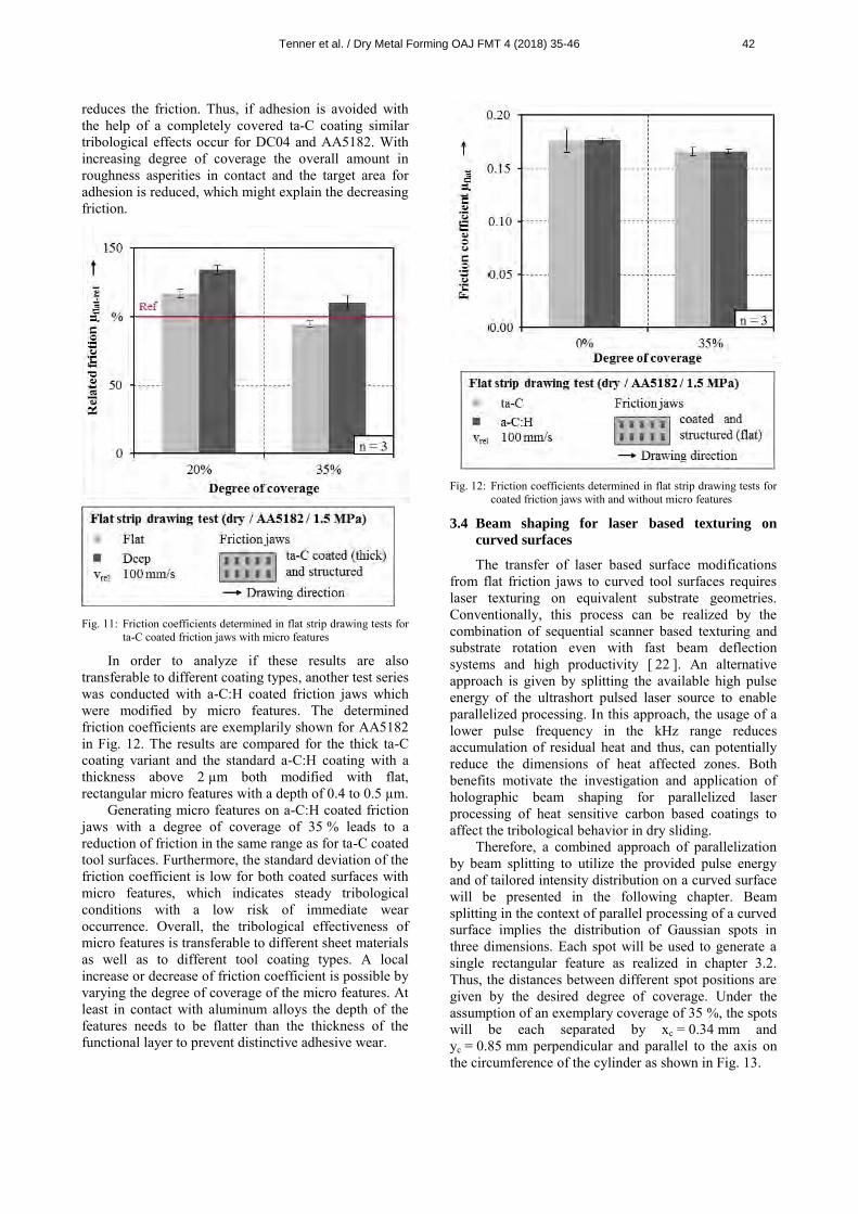
reduces the friction. Thus, if adhesion is avoided with the help of a completely covered ta-C coating similar tribological effects occur for DC04 and AA5182. With increasing degree of coverage the overall amount in roughness asperities in contact and the target area for adhesion is reduced, which might explain the decreasing friction.
Fig. 11: Friction coefficients determined in flat strip drawing tests for
ta-C coated friction jaws with micro features
In order to analyze if these results are also transferable to different coating types, another test series was conducted with a-C:H coated friction jaws which were modified by micro features. The determined friction coefficients are exemplarily shown for AA5182 in Fig. 12. The results are compared for the thick ta-C coating variant and the standard a-C:H coating with a thickness above 2 µm both modified with flat, rectangular micro features with a depth of 0.4 to 0.5 µm.
Generating micro features on a-C:H coated friction jaws with a degree of coverage of 35 % leads to a reduction of friction in the same range as for ta-C coated tool surfaces. Furthermore, the standard deviation of the friction coefficient is low for both coated surfaces with micro features, which indicates steady tribological conditions with a low risk of immediate wear occurrence. Overall, the tribological effectiveness of micro features is transferable to different sheet materials as well as to different tool coating types. A local increase or decrease of friction coefficient is possible by varying the degree of coverage of the micro features. At least in contact with aluminum alloys the depth of the features needs to be flatter than the thickness of the functional layer to prevent distinctive adhesive wear.
Fig. 12: Friction coefficients determined in flat strip drawing tests for
coated friction jaws with and without micro features
3.4 Beam shaping for laser based texturing on
curved surfaces
The transfer of laser based surface modifications from flat friction jaws to curved tool surfaces requires laser texturing on equivalent substrate geometries. Conventionally, this process can be realized by the combination of sequential scanner based texturing and substrate rotation even with fast beam deflection systems and high productivity [ 22 ]. An alternative approach is given by splitting the available high pulse energy of the ultrashort pulsed laser source to enable parallelized processing. In this approach, the usage of a lower pulse frequency in the kHz range reduces accumulation of residual heat and thus, can potentially reduce the dimensions of heat affected zones. Both benefits motivate the investigation and application of holographic beam shaping for parallelized laser processing of heat sensitive carbon based coatings to affect the tribological behavior in dry sliding.
Therefore, a combined approach of parallelization by beam splitting to utilize the provided pulse energy and of tailored intensity distribution on a curved surface will be presented in the following chapter. Beam splitting in the context of parallel processing of a curved surface implies the distribution of Gaussian spots in three dimensions. Each spot will be used to generate a single rectangular feature as realized in chapter 3.2. Thus, the distances between different spot positions are given by the desired degree of coverage. Under the assumption of an exemplary coverage of 35 %, the spots will be each separated by xc = 0.34 mm and yc = 0.85 mm perpendicular and parallel to the axis on the circumference of the cylinder as shown in Fig. 13.
Tenner et al. / Dry Metal Forming OAJ FMT 4 (2018) 35-46 42
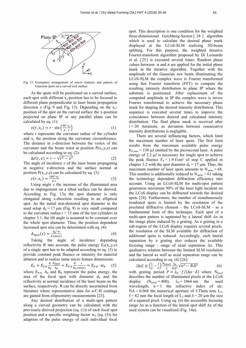
Fig. 13: Exemplary arrangement of micro features and pattern of
Gaussian spots on a curved tool surface
As the spots will be positioned on a curved surface, each spot with different xc-position has to be focused to different plane perpendicular to laser beam propagation direction z (Fig. 9 and Fig. 13). Depending on the xc-position of the spot on the curved surface the x-position projected on plane IP or any parallel plane can be calculated by eq. (1):
𝑥(𝑟, 𝑥𝑐) = 𝑟 ∙ sin (90°
𝜋
𝑥𝑐
𝑟) (1)
where r represents the curvature radius of the cylinder and xc the position along the curvature circumference. The distance in z-direction between the vertex of the curvature and the beam waist at position P(xc,y,z) can be calculated according to eq. (2):
∆𝑧(𝑟, 𝑥) = 𝑟 − √𝑟2 − 𝑥2 (2) The angle of incidence ε of the laser beam propagating in negative z-direction and the surface normal at position P(xc,y,z) can be calculated by eq. (3):
휀(𝑟, 𝑥𝑐) =180°∙𝑥𝑐
𝜋∙𝑟 (3)
Using angle ε the increase of the illuminated area due to impingement on a tilted surface can be derived. According to Fig. 13a the spot diameter is only elongated along x-direction resulting in an elliptical spot. As the initial non-distorted spot diameter in the used setup d0 = 17 µm (Fig. 9) is very small compared to the curvature radius r = 15 mm of the test cylinders in chapter 3.1, the tilt angle is assumed to be constant over the whole spot diameter. Thus, the position dependent increased spot size can be determined with eq. (4):
𝐴𝑆𝑝𝑜𝑡(휀) =𝑑0²∙𝜋
4∙cos(𝜀) (4)
Taking the angle of incidence depending reflectivity R into account, the pulse energy EP(xc,y,z) of a single spot has to be adapted according to eq. (5) to provide constant peak fluence or intensity for material ablation and to realize same micro feature dimensions:
𝐸𝑃 = 𝐸𝑃,0𝑅
𝑅0
𝐴𝑆𝑝𝑜𝑡
𝐴0= 𝐸𝑃,0
𝑅
𝑅0
1
cos(𝜀)= 𝐸𝑃,0 ∙ 𝑤𝐸 (5)
where EP,0, A0 and R0 represent the pulse energy, the area of the focal spot with diameter d0 and the reflectivity at normal incidence of the laser beam on the surface, respectively. R can be directly ascertained from literature where representative data for a-C:H coatings are gained from ellipsometry measurements [23].
Any desired distribution of a multi-spot pattern along a curved geometry can be calculated with the previously derived projection (eq. (1)) of each focal spot position and a specific weighting factor wE (eq. (5)) for adaption of the pulse energy of each individual focal
spot. This description is one condition for the weighted three-dimensional Gerchberg-Saxton [ 24 ] algorithm which is used to calculate the desired phase mask displayed at the LCoS-SLM realizing 3D-beam splitting. For this purpose, the weighted iterative Fourier-transform algorithm proposed by Di Leonardo et al. [25] is executed several times. Random phase values between -π and π are applied for the initial phase mask in the iterative algorithm. Together with the amplitude of the Gaussian raw beam illuminating the LCoS-SLM the complex wave is Fourier transformed using fast Fourier transform (FFT) to compute the resulting intensity distribution in plane IP where the substrate is positioned. After replacement of the computed amplitude in IP the complex wave is invers Fourier transformed to achieve the necessary phase mask for shaping the desired intensity distribution. This sequence is executed several times to improve the coincidence between desired and calculated intensity distribution. The final phase mask is received after i = 20 iterations, as deviation between consecutive intensity distributions is negligible.
There are several influencing factors, which limit the maximum number of laser spots. The first limit results from the maximum available pulse energy EP,max = 150 µJ emitted by the picosecond laser. A pulse energy of 2.2 µJ is necessary for single spot to achieve the peak fluence F0 = 1.9 J/cm² of step C applied in chapter 3.2 with the spot diameter d0 = 17 µm. Thus, the maximum number of laser spots amounts to Nspots = 68. This number is additionally reduced to Nspots = 61 taking the technology dependent diffraction efficiency into account. Using an LCoS-SLM for multi-spot pattern generation maximum 90% of the laser light incident on the LCoS display can be diffracted towards the desired spots [24]. Furthermore, the number of simultaneously irradiated spots is limited by the resolution of the pixelated diffractive element - the LCoS-SLM - as a fundamental limit of this technique. Each spot of a multi-spot pattern is separated by a lateral shift Δx in the image plane induced by a grating. As a grating in a sub-region of the LCoS display requires several pixels, the resolution of the SLM available for diffraction of additional spots is reduced. Accordingly, each lateral separation by a grating also reduces the available focusing range - range of axial separation Δz. This qualitative relation between the limited SLM resolution and the lateral as well as axial separation range can be calculated according to eq. (6) [26]:
|∆𝑧| ≤ (1
2−
1
𝑃)𝑁𝑝𝑖𝑥𝑒𝑙
2
𝜆0
𝑁𝐴2√𝑛2 − 𝑁𝐴2 (6)
with grating period 𝑃 = 𝜆0 ∙ 𝑓/(∆𝑥 ∙ 𝛿) where Npixel describes the number of illuminated pixels at the LCoS display (Npixel = 400), λ0 = 1064 nm the used wavelength, n = 1 the refractive index of air, NA = 0.068 the numerical aperture of f-Theta lens L3, f = 82 mm the focal length of L3 and δ = 20 µm the size of a squared pixel. Using eq. (6) the accessible focusing range Δz as a function of the lateral spot shift Δx of the used system can be visualized (Fig. 14a).
Tenner et al. / Dry Metal Forming OAJ FMT 4 (2018) 35-46 43
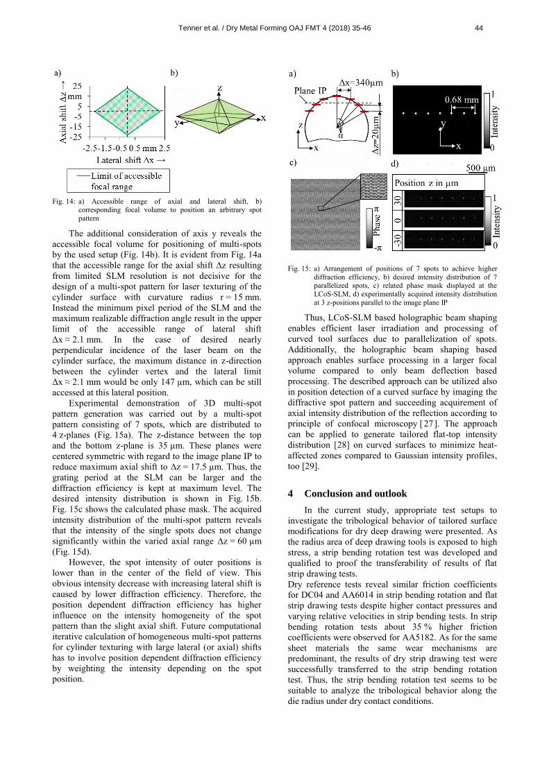
Fig. 14: a) Accessible range of axial and lateral shift, b)
corresponding focal volume to position an arbitrary spot pattern
The additional consideration of axis y reveals the accessible focal volume for positioning of multi-spots by the used setup (Fig. 14b). It is evident from Fig. 14a that the accessible range for the axial shift Δz resulting from limited SLM resolution is not decisive for the design of a multi-spot pattern for laser texturing of the cylinder surface with curvature radius r = 15 mm. Instead the minimum pixel period of the SLM and the maximum realizable diffraction angle result in the upper limit of the accessible range of lateral shift Δx ≈ 2.1 mm. In the case of desired nearly perpendicular incidence of the laser beam on the cylinder surface, the maximum distance in z-direction between the cylinder vertex and the lateral limit Δx ≈ 2.1 mm would be only 147 µm, which can be still accessed at this lateral position.
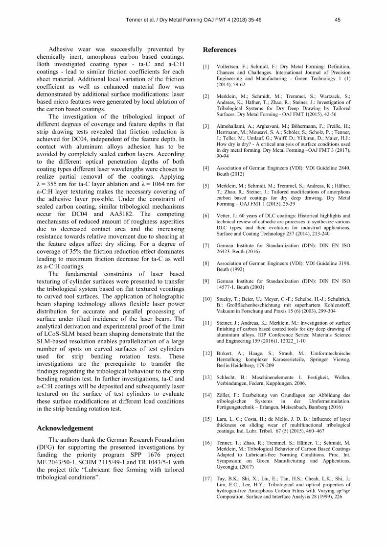
Experimental demonstration of 3D multi-spot pattern generation was carried out by a multi-spot pattern consisting of 7 spots, which are distributed to 4 z-planes (Fig. 15a). The z-distance between the top and the bottom z-plane is 35 µm. These planes were centered symmetric with regard to the image plane IP to reduce maximum axial shift to Δz = 17.5 µm. Thus, the grating period at the SLM can be larger and the diffraction efficiency is kept at maximum level. The desired intensity distribution is shown in Fig. 15b. Fig. 15c shows the calculated phase mask. The acquired intensity distribution of the multi-spot pattern reveals that the intensity of the single spots does not change significantly within the varied axial range Δz = 60 µm (Fig. 15d).
However, the spot intensity of outer positions is lower than in the center of the field of view. This obvious intensity decrease with increasing lateral shift is caused by lower diffraction efficiency. Therefore, the position dependent diffraction efficiency has higher influence on the intensity homogeneity of the spot pattern than the slight axial shift. Future computational iterative calculation of homogeneous multi-spot patterns for cylinder texturing with large lateral (or axial) shifts has to involve position dependent diffraction efficiency by weighting the intensity depending on the spot position.
Fig. 15: a) Arrangement of positions of 7 spots to achieve higher
diffraction efficiency, b) desired intensity distribution of 7 parallelized spots, c) related phase mask displayed at the LCoS-SLM, d) experimentally acquired intensity distribution at 3 z-positions parallel to the image plane IP
Thus, LCoS-SLM based holographic beam shaping enables efficient laser irradiation and processing of curved tool surfaces due to parallelization of spots. Additionally, the holographic beam shaping based approach enables surface processing in a larger focal volume compared to only beam deflection based processing. The described approach can be utilized also in position detection of a curved surface by imaging the diffractive spot pattern and succeeding acquirement of axial intensity distribution of the reflection according to principle of confocal microscopy [ 27]. The approach can be applied to generate tailored flat-top intensity distribution [28] on curved surfaces to minimize heat-affected zones compared to Gaussian intensity profiles, too [29].
4 Conclusion and outlook
In the current study, appropriate test setups to investigate the tribological behavior of tailored surface modifications for dry deep drawing were presented. As the radius area of deep drawing tools is exposed to high stress, a strip bending rotation test was developed and qualified to proof the transferability of results of flat strip drawing tests. Dry reference tests reveal similar friction coefficients for DC04 and AA6014 in strip bending rotation and flat strip drawing tests despite higher contact pressures and varying relative velocities in strip bending tests. In strip bending rotation tests about 35 % higher friction coefficients were observed for AA5182. As for the same sheet materials the same wear mechanisms are predominant, the results of dry strip drawing test were successfully transferred to the strip bending rotation test. Thus, the strip bending rotation test seems to be suitable to analyze the tribological behavior along the die radius under dry contact conditions.
Tenner et al. / Dry Metal Forming OAJ FMT 4 (2018) 35-46 44
Adhesive wear was successfully prevented by chemically inert, amorphous carbon based coatings. Both investigated coating types - ta-C and a-C:H coatings - lead to similar friction coefficients for each sheet material. Additional local variation of the friction coefficient as well as enhanced material flow was demonstrated by additional surface modifications: laser based micro features were generated by local ablation of the carbon based coatings.
The investigation of the tribological impact of different degrees of coverage and feature depths in flat strip drawing tests revealed that friction reduction is achieved for DC04, independent of the feature depth. In contact with aluminum alloys adhesion has to be avoided by completely sealed carbon layers. According to the different optical penetration depths of both coating types different laser wavelengths were chosen to realize partial removal of the coatings. Applying λ = 355 nm for ta-C layer ablation and λ = 1064 nm for a-C:H layer texturing makes the necessary covering of the adhesive layer possible. Under the constraint of sealed carbon coating, similar tribological mechanisms occur for DC04 and AA5182. The competing mechanisms of reduced amount of roughness asperities due to decreased contact area and the increasing resistance towards relative movement due to shearing at the feature edges affect dry sliding. For a degree of coverage of 35% the friction reduction effect dominates leading to maximum friction decrease for ta-C as well as a-C:H coatings.
The fundamental constraints of laser based texturing of cylinder surfaces were presented to transfer the tribological system based on flat textured vcoatings to curved tool surfaces. The application of holographic beam shaping technology allows flexible laser power distribution for accurate and parallel processing of surface under tilted incidence of the laser beam. The analytical derivation and experimental proof of the limit of LCoS-SLM based beam shaping demonstrate that the SLM-based resolution enables parallelization of a large number of spots on curved surfaces of test cylinders used for strip bending rotation tests. These investigations are the prerequisite to transfer the findings regarding the tribological behaviour to the strip bending rotation test. In further investigations, ta-C and a-C:H coatings will be deposited and subsequently laser textured on the surface of test cylinders to evaluate these surface modifications at different load conditions in the strip bending rotation test.
Acknowledgement
The authors thank the German Research Foundation (DFG) for supporting the presented investigations by funding the priority program SPP 1676 project ME 2043/50-1, SCHM 2115/49-1 and TR 1043/5-1 with the project title “Lubricant free forming with tailored tribological conditions”.
References
[1] Vollertsen, F.; Schmidt, F.: Dry Metal Forming: Definition,
Chances and Challenges. International Journal of Precision Engineering and Manufacturing - Green Technology 1 (1) (2014), 59-62
[2] Merklein, M.; Schmidt, M.; Tremmel, S.; Wartzack, S.; Andreas, K.; Häfner, T.; Zhao, R.; Steiner, J.: Investigation of Tribological Systems for Dry Deep Drawing by Tailored Surfaces. Dry Metal Forming - OAJ FMT 1(2015), 42-56
[3] Almohallami, A.; Arghavani, M.; Böhermann, F.; Freiße, H.; Herrmann, M.; Mousavi, S. A.; Schöler, S.; Scholz, P. ; Tenner, J.; Teller, M.; Umlauf, G.; Wulff, D.; Yilkiran, D.; Maier, H.J.: How dry is dry? - A critical analysis of surface conditions used in dry metal forming. Dry Metal Forming –OAJ FMT 3 (2017), 90-94
[4] Association of German Engineers (VDI): VDI Guideline 2840. Beuth (2012)
[5] Merklein, M.; Schmidt, M.; Tremmel, S.; Andreas, K.; Häfner, T.; Zhao, R.; Steiner, J.: Tailored modifications of amorphous carbon based coatings for dry deep drawing. Dry Metal Forming – OAJ FMT 1 (2015), 25-39
[6] Vetter, J.: 60 years of DLC coatings: Historical highlights and technical review of cathodic arc processes to synthesize various DLC types, and their evolution for industrial applications. Surface and Coating Technology 257 (2014), 213-240
[7] German Institute for Standardization (DIN): DIN EN ISO 26423. Beuth (2016)
[8] Association of German Engineers (VDI): VDI Guideline 3198. Beuth (1992)
[9] German Institute for Standardization (DIN): DIN EN ISO 14577-1. Beuth (2003)
[10] Stucky, T.; Beier, U.; Meyer, C.-F.; Scheibe, H.-J.; Schultrich, B.: Großflächenbeschichtung mit superhartem Kohlenstoff. Vakuum in Forschung und Praxis 15 (6) (2003), 299-304
[11] Steiner, J.; Andreas, K.; Merklein, M.: Investigation of surface finishing of carbon based coated tools for dry deep drawing of aluminium alloys. IOP Conference Series: Materials Science and Engineering 159 (2016)1, 12022_1-10
[12] Birkert, A.; Haage, S.; Straub, M.: Umformtechnische Herstellung komplexer Karosserieteile, Springer Vieweg, Berlin Heidelberg, 179-209
[13] Schlecht, B.: Maschinenelemente 1. Festigkeit, Wellen, Verbindungen, Federn, Kupplungen. 2006.
[14] Zöller, F.: Erarbeitung von Grundlagen zur Abbildung des tribologischen Systems in der Umformsimulation. Fertigungstechnik – Erlangen, Meisenbach, Bamberg (2016)
[15] Lara, L. C.; Costa, H.; de Mello, J. D. B.: Influence of layer thickness on sliding wear of multifunctional tribological coatings. Ind. Lubr. Tribol. 67 (5) (2015), 460–467
[16] Tenner, T.; Zhao, R.; Tremmel, S.; Häfner, T.; Schmidt, M. Merklein, M.: Tribological Behavior of Carbon Based Coatings Adapted to Lubricant-free Forming Conditions. Proc. Int. Symposium on Green Manufacturing and Applications, Gyeongju, (2017)
[17] Tay, B.K.; Shi, X.; Liu, E.; Tan, H.S.; Cheah, L.K.; Shi, J.; Lim, E.C.; Lee, H.Y.: Tribological and optical properties of hydrogen-free Amorphous Carbon Films with Varying sp³/sp² Composition. Surface and Interface Analysis 28 (1999), 226
Tenner et al. / Dry Metal Forming OAJ FMT 4 (2018) 35-46 45
[18] Häfner, T.; Heberle, J.; Hautmann, H.; Zhao, R.; Tenner, J.;
Tremmel, S.; Merklein, M.; Schmidt, M.: Effect of picosecond laser based modifications of amorphous carbon coatings on lubricant-free tribological systems. Journal of Laser Micro Nanoengineering (2017), 132-140
[19] Robertson, J.: Diamond-like amorphous carbon. Mat. Sc. and Eng. R37 (2002), 129-181
[20] Grill, A.: Electrical and optical properties of diamond-like carbon. Thin Solid Films (1999), 189-193
[21] Merklein, M.; Schmidt, M.; Tremmel, S.; Andreas, K.; Häfner, T.; Zhao, R.; Tenner (geb. Steiner), J.: Tailored modifications of amorphous carbon based coatings for dry deep drawing. Dry Metal Forming - OAJ FMT 2 (2016), 25-39
[22] Bruening, S. et al.: Ultrafast Scan Techniques for 3D-μm Structuring of Metal Surfaces with high repetitive ps-laser pulses. Phys. Procedia. (2011), 105-115
[23] Smith, F.W.: Optical constants of a hydrogenated amorphous carbon film. J. Appl. Phys. 55 (1984), 764-771
[24] Whyte, G.; Courtial, J.: Experimental demonstration of holographic three-dimensional light shaping using Gerchberg-Saxton algorithm. New Journal of Physics 7 (2005), 117
[25] Di Leonardo, R.; Ianni, F.; Ruocco, G.: Computer generation of optimal holograms for optical trap arrays. Opt. Expr. Vol. 15(4) (2007), 1913-1922
[26] Cvecek, K.; Eckl, J.; Eiselen, S.; Huber, H.; Schmidt, M.: Evaluation of Scanner-Based Focus Finding Methods on Rough Surfaces. JLMN 10 (3) (2015), 304-309
[27] Jesacher, A.; Roider, C.; Ritsch-Marte, M.: Enhancing diffractive multi-plane microscopy using colored illumination. Opt. Exp. 21 (9) (2013), 11150-11161
[28] Häfner, T.; Strauß, J.; Roider, C.; Heberle J.; Schmidt, M.: Tailored laser beam shaping for efficient and accurate micro-structuring. App. Phys. A (2018) accepted
[29] Rung, S.; Bischoff, C.; Jäger, E.; Umhofer, U.; Hellmann, R.: Proc. of SPIE 8967 (2014)
Tenner et al. / Dry Metal Forming OAJ FMT 4 (2018) 35-46 46