dry mine abandonment - ftp directory listing - brouard consulting
TRANSCRIPT
Dry mine abandonment
Berest, Pierre1 Brouard, Benoit2 Feuga, Bernard3
Ecole Polytechnique, Palaiseau, France1
Brouard Consulting, Paris, France2 BRGM, Orleans, France3
_______________
first presented during the SMRI Fall 2003 Conference in Chester, United Kingdom
Spring 2004 Conference 18 – 21 April
Wichita, Kansas, USA
SOLUTION MINING RESEARCH INSTITUTE 1219 Bittersweet Drive
Richmond, Texas 77469-6544, USA
Telephone and Fax: 281-232-8766
www.solutionmining.org [email protected]
TTeecchhnniiccaall CCoonnffeerreennccee
PPaappeerr
DRY MINE ABANDONMENT
BEREST Pierre1, BROUARD Benoît2, FEUGA Bernard3
1Laboratoires LMS et G3S, Ecole polytechnique, Palaiseau 91128 Cedex - France. [email protected]
Tél. 01 69 33 41 28 - Fax 01 69 33 30 28
2Brouard Consulting, 37 rue du petit-musc, 75004 Paris - France. [email protected]
Tél. 01 42 72 42 23 – Fax 01 69 33 30 28
3 BRGM, REM/RESE BP 6009 – 45060 Orléans cedex 2 – France. [email protected]
ABSTRACT: The abandonment of dry salt mines raises a difficult problem, as post-abandonment mine flooding is, in most cases, highly probable, with possible severe consequences at ground level. Several cases of active mine flooding are analyzed to compare the advantages and drawbacks of deliberate mine flooding before abandonment. Special attention is paid to the possible degradation of the marly floor layers.

- 2 - - 1 INTRODUCTION When analyzing the post-abandonment behavior of a dry mine, lessons drawn from the behavior of active mines must be taken into account. Salt mines experience a slow closure: pillars left between the galleries to support the roof during salt extraction gradually shrink; mine roofs sag; and, at the end of the process, the mines close completely, as observed in very deep mines where the process is faster. Mine closure induces overburden sagging and surface subsidence. In most cases, this process is extremely slow; its rate can be measured and predicted (Van Sambeek, 2000); it will end after a period of time that is so long (centuries or dozens of centuries) that it has no practical consequences for human activities. Several active mines have experienced rapid evolutions, two types of which can be distinguished:
(1) collapse of poorly dimensioned mines (In most cases, in such mines, the extraction ratio was too large when compared to the weight of the overburden.); and
(2) mine flooding leading to mine abandonment.
In fact, mine flooding is sometimes a direct consequence of roof collapse, as in the Retsof case (Paragraph 2.4). However, in the 1873 Varangéville Mine collapse (Paragraph 6.2), no water flow took place after the crater formed. This paper focuses on mine flooding, as it is the most frequent, as well as the most specific, accident when salt or potash mines are considered. While one tries to draw general lessons from case stories, it must be kept in mind that local circumstances often play a major role. As an example, consider the following two main categories of salt masses:
• Bedded Salt Formations, which remain approximately horizontal after they are deposited — Extraction often is managed in a layer that is several meters thick (dry mine) or a several dozens of meters thick (solution-mined caverns) located in a series of strata that include less soluble layers. These layers exhibit diverse mechanical properties, ranging from stiff anhydrite layers to the weak and alterable marls or argilite layers. This configuration can be found, for instance, in the USA (Kansas, the Permian Wellington formation; New York State, the Upper Silurian Salina Group) or in France (Lorraine, the Lower Keuper formation).
• Domal Salt Formations, which result from salt rise during geological times — The driving force for such a vertical movement is the low density of rock salt, although tectonic forces sometimes play a role. The vertical extension of these formations is large, allowing salt extraction to take place deep below the salt top, which is often located at shallow depth (Gulf of Mexico.) Domal salt is often pure — except in anomalous zones, where black salt, gas or brine pockets, and large shear stresses can be found near the flanks of the dome, at the interface between two salt masses experiencing differential displacements; or in heterogeneous zones, which contain other soluble evaporites as potash or carnallite and/or marls or anhydrite layers, often in a nearly vertical position (northern Germany). In the last case, extraction methods often differ from the standard “room-and-pillar” method used in salt-bedded formations or the salt domes of the Gulf of Mexico.

2. MINE FLOODING 2.1 Common Accidents Flooding of salt mines is a relatively frequent accident, especially in old mining works: salt was mined at shallow depth in the vicinity of “salt outcrops” (i.e., salt springs), where mining works were contiguous to zones in which the salt mass was in direct contact with ground waters. Despite considerable advances in exploration and production techniques, this type of accident remains quite common, and many recent cases are described in the literature. 2.1.1 France In Lorraine, five dry mines (Vic-sur-Seille, Dieuze, Saint Nicolas, Rosières and Einville — Rosières and Saint Nicolas were linked to form the Varangéville Mine) have been in operation since the origin of salt production in this area. Two additional shafts were dug to the floor of the 11th layer of the salt formation at Tonnoy and Crevic, but no mine was worked from these two shafts. The Vic-sur-Seille Mine, opened in 1821, was abandoned a few years later, because water or unsaturated brine inflow could not be controlled. The Dieuze Mine, whose roof was 115 m deep, was flooded by saturated brine in 1864, although flooding had no direct relation with the mine itself. (It was the consequence of the collapse of a 60-m deep room connected to the mine shaft.) Only two dry mines are still open. The smaller of these is Einville, which is open but no longer active. The larger is Varangéville, a still active mine. Several other mines have been flooded elsewhere in France: Larralde, 1901; Saint Pandelon, 1905-1962; Saint Pierre, located in the center of the city of Dax, 1894 (DARPMI, 2001.) 2.1.2 United States In the United States, the mines excavated in the five domes of the so-called "Five Islands" dome row in the state of Louisiana, near the Gulf of Mexico (Figure 1), provide typical examples of mine flooding. A mine was created in each of these domes. Belle Isle was abandoned (Walters, 1978) after severe water leaks through a shaft casing took place; Jefferson Island was flooded in a few hours (O'Gorman and Stafford, 1980; Thoms and Gehle, 1994) after an oil exploration well, operated from a lake, hit the mine (1980); the Weeks Island Mine had been converted to oil storage but was abandoned (Bauer et al., 2000) after two sinkholes, connecting shallow unsaturated waters with the mine, appeared unexpectedly at ground level (1995). Cote Blanche and Avery Island are still in operation. Outside of Louisiana, several recent floodings should be noted. The Retsof Mine, probably the largest salt mine in the world, was flooded in 1994-1995 because of roof collapse in an area where yield pillars were used (Gowan and Trader, 2000; Gowan et al., 1999; Payment, 2000; Van Sambeek, 1996; Van Sambeek et al., 2000). The Winnfield Mine was flooded (1965) after a horizontal brine flow unexpectedly jetted from a pillar (Thoms and Gehle, 2000.) 2.1.3 Germany In Germany, many cases of salt- or potash-mine flooding were reported. Rölleke (2000, p.88) states: “…as potash salt mining has developed, mines in Germany have been hit by a number of uncontrolled water influxes which have resulted in spectacular subsidence and the creation of sinkholes.” He describes three case histories for mines in northern Germany (Vienenburg I, 1930; Hedwigsburg, 1921; and Ronnenberg, 1975, which will be discussed below.) Thoma et al. (2000) describe eight floods that hit mines in Central Germany.
- 4 - - 2.2 Flooding Mechanism A dry mine is filled with air at atmospheric pressure — i.e., much lower than the pressure in the overlying or underlying aquifer layers. When pathways are created between the mine and these layers, flow toward the mine occurs. 2.2.1 Access to the Mine: Natural Discontinuities In general, salt masses are extremely impermeable, and, in natural conditions, no fracture exists except perhaps under very special circumstances, as in the vicinity of a major fault or close to the flanks of a salt dome. This factor may have played a role in the Winnfield Mine flooding (Thoms and Gehle, 2000). The LOOP oil storage near New Orleans provides another example, although in a somewhat different context (McCauley et al., 1998; Lolan et al., 1998). Mud cracks can also be observed in bedded salt. (In the Varangéville Mine, they are vertical, a few meters high, not interconnected, filled with insolubles, and probably quite impermeable.) However, surprises can occur, especially in the few dozens of meters below the salt roof, which can be affected by complex phenomena during or after salt deposition. At the Holle Mine (Republic of Congo, formerly Congo-Brazzaville), galleries were dug out below a 35-m to 55-m thickness of salt; the observed minimum was 16 m. No fault or fracture had been encountered over 8 years of operation. On June 17, 1977, a flow ingress and a fall of materials, characteristic of the levels above the salt roof, were observed. At this specific location, the salt roof was 70 m above the galleries. On June 20, a large water flow appeared, and rocky blocks fell into the gallery; the flow rate was 30 m3/h, and the brine NaCl content decreased. By June 21, the flow rate was as large as 1650 m3/h and increased to 10,000 m3/h or more on June 22. A large conical crater, 150 m in diameter and 20-m deep, developed at ground level. The final flow-rate acceleration is typical (see Paragraph 2.3), but, at this step, the main lesson to be drawn is that, in natural conditions, no significant natural brine flow can be observed: in order for water to flow to the mine, pathways need to be created or activated. 2.2.2 Shafts and Wells In some cases, pathways simply are the shafts or wells that provide access to the salt formation, particularly the annular space between the steel casing and the rock mass, through which small fluid flow may remain long unnoticed. Special attention is paid to these areas during shaft digging (rock freezing) and well completion (mobile casings, use of bitumen, etc.), but accidents sometimes occur. Rock freezing was not used during the digging of the second Belle Isle shaft, which led to water inflow and, ultimately, mine abandonment. The mine level is sometimes crossed by wells whose ends are far below the mine. Such wells must be protected by large massive pillars; otherwise, they can provide a pathway to the mine. Two cases (with no mine voids) , the Haoud Berkaoui well and the Dieuze Brejcha well, are discussed below. At the Jefferson Island Mine, an oil exploration well was drilled close to the mine edges and provided a very effective pathway for surface water to enter the mine.
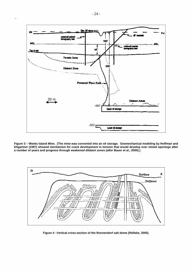
- 5 - - 2.2.3 The Jefferson Island Case The Jefferson Island dome is located 30 km south of Lafayette, Louisiana. A mine had been operating there since 1920. Several levels had been mined. In November 1980, the mine volume was 16-million cubic meters (Johnson, 2001), and salt was extracted from the 1500-ft (500-m) deepest level (Figure 2). Above the mine is Lake Peigneur, which held 7-million cubic meters of water prior to the accident. A drilling rig was on the bottom mud of the lake. On November 20, the drill reached 370 m, at which point fluid circulation was lost when one of the mine chambers was penetrated. The rig began to tilt. A whirlpool, 400 m in diameter, formed, and the well diameter rapidly increased from a couple of decimeters to 10 m, due to rapid erosion-dissolution of salt. The entire lake disappeared into a crater formed where the rig had been (Easley, 2000), leading to mine flooding. Fortunately, the 50 miners in the mine were able to evacuate safely (O'Gorman and Stafford, 1980; Thoms and Gehle, 1994.) 2.2.4 Induced Discontinuities Mining can generate large stress redistribution — not large enough to be a threat to mine stability, but large enough to allow discontinuities to open and provide access to the mine through created or activated discontinuities. The Weeks Island case is typical (Figure 3). This is a two-level room-and-pillar mine with the two levels, measured to the mine floor, 163-m (from 1902 to 1955) and 224-m (from 1955 to 1976) below the surface, respectively. The room height was 22 m to 23 m, the pillars were 30.5-m wide, and the rooms were 15.2-m wide, resulting in an extraction ratio of 55% (Bauer et al., 2000; Hoffman and Ehgartner,1996). Two sinkholes, the first one in 1992, appeared above the edge of the mine. This location is logical, as bending of the thick salt slab left between the mine roof and the dome top generates large tensile stresses in the area. Sinkhole creation was unexpected because the mine, which was stable during mining operations (Carosella, 1978), had been converted to an oil storage facility in 1981 and contained such (relatively) high fluid pressure in the mine that drastic mechanical evolutions did not seem likely. In this case, discontinuities were created inside the salt mass itself; in other cases, the discontinuity appears in non-halitic layers that cross the salt mass. One of the latter cases, the Ronnenberg case, is described below. 2.3 Rapid Flow Increase Water inflow is a very common phenomenon in all types of mines. Salt mines, however, are very sensitive to water inflow: a small amount of initial brine inflow may increase drastically as unsaturated brine leaches out the pathways through which it percolates to the mine. 2.3.1 Mechanism Typically, initial access to a dry mine can be gained through a very thin discontinuity, either activated or induced by mining operations. At the beginning of the process, the discontinuity allows a very small amount of brine to travel from the source of water to the mine through the salt formation. The water has enough time to become saturated long before it reaches the mine, but the pathway enlarges slowly, beginning at the point where the water enters the pathway and progressively reducing head losses. This evolution remains unnoticed while the brine flow increases slowly, and the line separating unsaturated brine from fully saturated brine slowly progresses to the mine. When it reaches the mine, the process
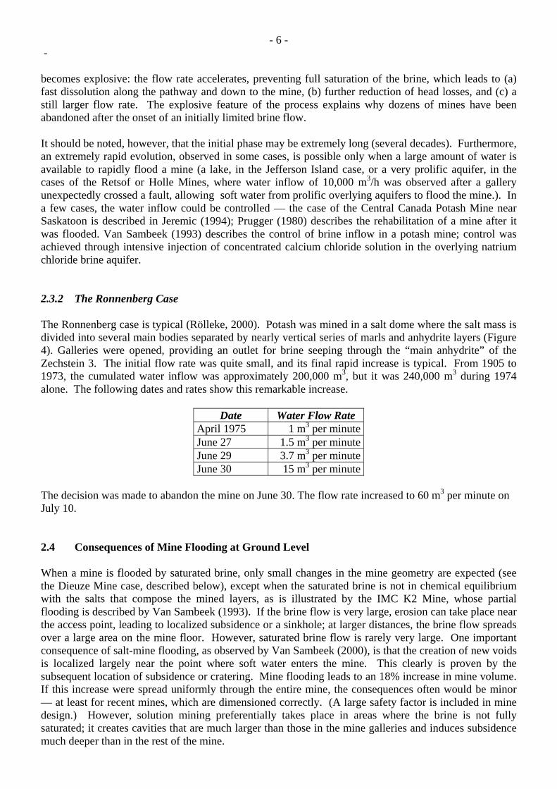
- 6 - - becomes explosive: the flow rate accelerates, preventing full saturation of the brine, which leads to (a) fast dissolution along the pathway and down to the mine, (b) further reduction of head losses, and (c) a still larger flow rate. The explosive feature of the process explains why dozens of mines have been abandoned after the onset of an initially limited brine flow. It should be noted, however, that the initial phase may be extremely long (several decades). Furthermore, an extremely rapid evolution, observed in some cases, is possible only when a large amount of water is available to rapidly flood a mine (a lake, in the Jefferson Island case, or a very prolific aquifer, in the cases of the Retsof or Holle Mines, where water inflow of 10,000 m3/h was observed after a gallery unexpectedly crossed a fault, allowing soft water from prolific overlying aquifers to flood the mine.). In a few cases, the water inflow could be controlled — the case of the Central Canada Potash Mine near Saskatoon is described in Jeremic (1994); Prugger (1980) describes the rehabilitation of a mine after it was flooded. Van Sambeek (1993) describes the control of brine inflow in a potash mine; control was achieved through intensive injection of concentrated calcium chloride solution in the overlying natrium chloride brine aquifer. 2.3.2 The Ronnenberg Case The Ronnenberg case is typical (Rölleke, 2000). Potash was mined in a salt dome where the salt mass is divided into several main bodies separated by nearly vertical series of marls and anhydrite layers (Figure 4). Galleries were opened, providing an outlet for brine seeping through the “main anhydrite” of the Zechstein 3. The initial flow rate was quite small, and its final rapid increase is typical. From 1905 to 1973, the cumulated water inflow was approximately 200,000 m3, but it was 240,000 m3 during 1974 alone. The following dates and rates show this remarkable increase.
Date Water Flow Rate April 1975 1 m3 per minuteJune 27 1.5 m3 per minuteJune 29 3.7 m3 per minuteJune 30 15 m3 per minute
The decision was made to abandon the mine on June 30. The flow rate increased to 60 m3 per minute on July 10. 2.4 Consequences of Mine Flooding at Ground Level When a mine is flooded by saturated brine, only small changes in the mine geometry are expected (see the Dieuze Mine case, described below), except when the saturated brine is not in chemical equilibrium with the salts that compose the mined layers, as is illustrated by the IMC K2 Mine, whose partial flooding is described by Van Sambeek (1993). If the brine flow is very large, erosion can take place near the access point, leading to localized subsidence or a sinkhole; at larger distances, the brine flow spreads over a large area on the mine floor. However, saturated brine flow is rarely very large. One important consequence of salt-mine flooding, as observed by Van Sambeek (2000), is that the creation of new voids is localized largely near the point where soft water enters the mine. This clearly is proven by the subsequent location of subsidence or cratering. Mine flooding leads to an 18% increase in mine volume. If this increase were spread uniformly through the entire mine, the consequences often would be minor — at least for recent mines, which are dimensioned correctly. (A large safety factor is included in mine design.) However, solution mining preferentially takes place in areas where the brine is not fully saturated; it creates cavities that are much larger than those in the mine galleries and induces subsidence much deeper than in the rest of the mine.
- 7 - - The flooding of the Retsof Mine provides a good example (Gowan et al., 1999). Rooms were 12-ft (3.6-m) high. Two sinkholes appeared during the weeks following the March 12, 1994 roof collapse and panel flooding that took place in the 2YS panel. The first sinkhole, located above 2YS, was 15-ft (4.5-m) deep; the second sinkhole, located above the neighboring 11YW panel, was 70-ft (21-m) deep — i.e., its depth was much larger than the height of the galleries and even larger than the total salt-layer thickness (Figure 5). When, at the Ronnenberg potash mine (Paragraph 2.3.2), it became clear that the mine had to be abandoned and that severe consequences were expected below densely inhabited areas, it was decided to deliberately inject water in the mine through 2 new wells in order to redistribute water inflow more evenly and transfer flooding consequences to less sensitive areas (Rölleke, 2000). In the Holle Mine (Congo), the trough created by flooding this carnallite mine was 150 m in diameter and 20-m deep, even though the galleries were only a few meters high. The Wapno Mine in Poland provides another example (A. Kunstman, personal communication; a complete description is available in Kunstman and Urbanczyk, 2003.) In 1911, a mine was opened in a small and relatively shallow salt dome partially located below the city of Wapno. From 1911 to 1960, salt was extracted from ten different levels, ranging from 384-m to 683-m deep. Galleries were dug out according to the so-called "fish-bones" pattern. Galleries were 15-m wide, 15-m high, and 100-m to 150-m long; pillars were 15-m wide. After 1960, extraction started again in the 384-m deep level; pillars were made thinner and higher. A 1-liter/minute brine flow appeared. Its density was 1.29 g/l, and its K and Mg contents were high. Analysis of the tritium contained in the brine proved that water was originating from outside the dome. Between 1972 and 1976, the brine density decreased, and the brine flow rate and NaCl content increased. These data prove that brine likely flowed toward the mine through fractures that were filled initially with K and Mg; complete leaching of these minerals took years. The zone where the brine flow entered the mine experienced large stresses, due to the high extraction ratio reached after 1960. Computations proved that tensile stresses were present at the gallery roof in this zone. The brine flow rate increased and reached 530 liters/minute on August 3, 1977, when it was decided to abandon the mine. A sudden brine inflow (15,000 m3 in 15 minutes) was observed on August 5 in the 384-m deep level; the water originated from old shallow gypsum mines located above the salt mine, which had been flooded years before. Note that the most severe disorders at ground level were not observed above the mine but, rather, several hundred meters away from the salt dome’s largest horizontal extension. In fact, the largest sinkholes resulted from shallow sand suffosion to the old gypsum mines, from which water entered the salt mine. More than 50 buildings and 1400 people were evacuated from the city. To minimize the impact of the uncontrolled mine flooding, the mine flooding rate was increased by injecting soft water from a nearby lake. The possible formation of sinkholes located outside the mine horizontal contour and the frequent creation of sinkholes and troughs significantly deeper than the mine height are two characteristic features of salt- mine flooding. In most cases, however, the flooded mine is more stable than the dry mine had been (see Paragraph 4.3). 2.5 Accidental Post-Abandonment Flooding We did not find any post-abandonment flooding cases described in the literature, probably because most mines either are still in operation or were flooded during operation or before abandonment. The post-abandonment collapse of the Tennant dry mine, in Northern Ireland, is described in Griffith (1991). In France, among eight known salt mines, one is still in operation, one is inactive but monitored, five were flooded, and one collapsed but was not flooded. A few interesting post-abandonment accidents are described.
- 8 - - When not properly plugged, shafts are a weak point after mine abandonment. Active operation of the Little River Salt Mine, Kansas, ceased in 1926, but the mine was kept open until 1938, when it was abandoned with the shaft left open and unsealed (Walters, 1978). The depth to the mine floor was 796 ft (240 m). The shaft, which originally measured 7 ft by 17 ft (2 m x 5 m) had deteriorated due to fresh water seepage over 25 years. In 1975, new owners considered storing propane in the mine. Three wells were drilled, one of them through the debris-filled shaft. A sonar survey showed considerable enlargement at the shaft bottom (A cavern, 60-ft high and 200-ft wide, had been washed out at the mine level.) and above the salt roof, at a depth of 560 ft, where shales with halite-filled vertical joints are found. (These joints are quite unstable in the presence of soft water or air.) The shaft was grouted, and the mine was later operated as an LPG storage (Walters, 1978.) During the 2002 SMRI Spring Meeting, Leo Van Sambeek made an oral presentation concerning an accident that occurred in an old abandoned salt mine at Kanopolis, Kansas, USA. We took a few notes (provided below); we hope they are reasonably accurate. The Kanopolis mine was abandoned in 1948. Its volume was 2.3-million cubic meters, with a depth of 790 ft (240 m). Its three access shafts were plugged with sand, rock, straw, etc. After the mine was abandoned, water flowed into it through the access shafts. (Before the mine was abandoned, water flow of 5 gallons per minute (1.2 m3/hr) was estimated for each of the three wells.) Air pressure slowly built up in the mine (indirect proof of salt impermeability in this context). The mine was converted to a kind of (natural) compressed air storage. In 1971, one of these three shafts experienced subrosion and shaft-filling collapse (Walters, 1978), an accident very similar to what happened at the Little River Salt Mine described above. A brick factory had been built above the abandoned mine, and bricks were piled above the head of one of the three shafts. (The pile volume was several thousands of cubic meters; the shaft head was hidden below ground at that time; and the shaft section was rectangular.) Later events have proven that the shaft had remained intact for 50 years. (The location of the pile above the shaft is not, in our opinion, a coincidence; the company took advantage of a railway access that existed when the mine was still active.) On October 26, 2000, shaft-filling material suddenly dropped into the mine, opening a sinkhole that was filled partially with some of the brick pile. The pressurized air then began to blow out from the mine through the shaft, generating a “brick rain” — bricks were flung upward to 50 m, and the “rain” lasted approximately 20 minutes. There were no casualties, but a warehouse was damaged severely. Van Sambeek presented estimates of the air flow rate through the shaft, and his calculations convincingly explained the observed facts. 3 SALT-MINE ABANDONMENT METHODS The facts presented above prove that salt-mine abandonment must be planned thoroughly, especially when such things as buildings, roads, canals or gas pipes can be found at ground level. This occurs frequently in densely inhabited areas of Europe, where salt mining was active in the past. The long-term stability of the mine must be discussed –a problem common to all mines, even if it must be kept in mind that, in the case of salt mines, a slow mine closure cannot be avoided. Mine flooding causes much more specific concerns, as its effects are more severe for salt and potash mines. Several abandonment methods can be considered.
- 9 - - 3.1 Filling the Mine with Solid Debris In most cases, this method is extremely costly, except perhaps when there are strong motives to dispose of solid wastes within a short distance from the mine or when an extreme value is attached to ground-level preservation. A recent example is provided by the Northwich Mines, Cheshire, UK, where a filling program (with debris, grout and brine) is underway. When a mine is filled with debris, the remaining voids are filled with brine to prevent any subsequent water flow (see Paragraph 4.1). In the Lapczyca area (between Wieliczka and Bochnia) in Poland (A. Kunstman, personal communication) unstable caverns are filled partially with sands to prevent any pollution that could result from cavern collapse. Of special concern in this respect is a river that provides drinkable water to a city. Sand injection is balanced by brine withdrawal in order to keep cavern pressure as constant as possible. 3.2 Intentional Mine Collapse Such a solution is often difficult to perform, as an exact assessment of mine stability is not an easy task — especially in modern mines, whose design includes a larger safety factor. In a different context (solution-mined caverns), Buffet (1998) describes a deliberate collapse: brine was pumped out from the cavern until the brine-air interface was located in the cavern itself, to remove the mechanical support provided to the cavern roof by the pressurized brine. This move proved to be not sufficient to lead to cavern collapse; further enlargement of the cavern through additional solution-mining was necessary to reach failure, and the total process took five years (Figure 7). 3.3 Indefinite Mine Monitoring Because subsequent change can be fast, the monitoring system must provide an early alert as soon as brine or water inflow appears. In the (extraordinary) Jefferson Island case, mine flooding was completed within a few hours; the Vienenburg Mine and Hedwigsburg Mine floodings were completed in 28 days and 2 days, respectively (Rölleke, 2000). At Retsof, the mine roof collapsed on March 12, 1994, and fissures immediately appeared at ground level. The first evidence of large (3-ft, or 1-m deep) subsidence was apparent by March 28; subsidence reached 12 ft (3.6 m) on April 6, and 60 ft (18 m) by mid-June (Figure 5). However, the complete flooding of the mine took 21 months (Gowan and Trader, 2000). In other cases (Weeks Island oil storage), events were spread over a much longer period, leaving enough time to make appropriate decisions (e.g., with regard to transferring oil to another site). Monitoring has several disadvantages. No definite monitoring end can be predicted, which means that the costs will be transferred to the state at some time. It also does not address the main concern of what must be done when water inflow appears. Should the population be evacuated? Should brine or water be injected rapidly into the mine to mitigate mine-flooding consequences? These questions must be answered before water inflow appears. 3.4 Filling the Mine with Water or Brine This solution has many advantages, and it is mandatory in northern Germany. It will be discussed more completely in the following.
- 10 - - 3.5 Regulations Injecting brine or water into a mine before abandonment is less costly than injecting solid materials, and it appears to be a logical process. Injecting fluids into a mine in controlled conditions is done in hope that the most probable accident (mine flooding) can be avoided or mitigated. As Northern Germany regulations state (Rölleke, 2000, p.93), “In salt mining, the mine workings must be flooded as a matter of principle after final shut-down operation. However it is necessary on a case-by-case basis to ensure that the planned flooding does not affect the integrity of the mine. If necessary, the mine must be flooded using for example NaCl or MgCl2 brines.” This general rule had only two exceptions, with the same origin — the existence in a mine of various types of salt exhibiting very different solubilities (As in this case, large dissolution of the more soluble salt is to be expected.) 4 ADVANTAGES OF MINE FILLING WITH WATER OR BRINE 4.1 Minimizing Head Gradients When mining works have been filled with brine, the mine is no longer a possible outlet for groundwaters, as rapid inflow is impossible because (a) no or small room is left for further inflow, and (b) when shafts have been filled with water or brine, the hydraulic head in the mine is larger than the fluid hydraulic head in the neighboring water-bearing formations. (Note that at the Weeks Island Mine, the mine had been filled with oil, which is lighter than water, resulting in lower-than-hydrostatic fluid pressure in the mine. Slow water inflow took place through fractures that developed above the edge of the mining works.) In fact, post-filling pressure distribution must be checked thoroughly: when the fluid/air interface in the shafts is equilibrated with the water table, brine pressure in the mine may be higher than the water pressure in surrounding water-bearing strata. Complex situations may develop, as when the mine shaft crosses water-bearing strata with distinct hydraulic heads, leading to possible fluid movements. In most cases, such movements will be much slower than the water displacements induced by unexpected mine flooding. Brine is heavier than water, and large water movements through a brine-filled mine can occur only if: (a) an aquifer layer exists beneath (or above) the mine and has a hydraulic head that is larger than the brine head in the mine (The Haoud Berkaoui case provides an illustration of this, although in a somewhat different context.), (b) a large hydraulic gradient exists between the possible inlet to and the possible outlet from the mine — a rare situation; or (c) water is deliberately pumped out from shallow aquifers above the mine. Maas (2001) describes the case of the Stassfurt area, where potash had been extracted since 1861. The part of the mine situated underneath the urban area was flooded unintentionally by fresh water between 1878 and 1922. The volume of the voids below the city was 10-million cubic meters. Active subsidence and sinkholes still occur today. Wide areas of the city are lower than the water-table level, and 1000 m3/day are pumped out to prevent these areas from being submerged; an adverse consequence is that pumping stimulates further dissolution in the mining works. It has even happened that, in some areas, brine is deliberately pumped out of a flooded mine ("bastard brining"), generally leading to rapid mine collapse (Rolfs and Crotogino, 2000.)
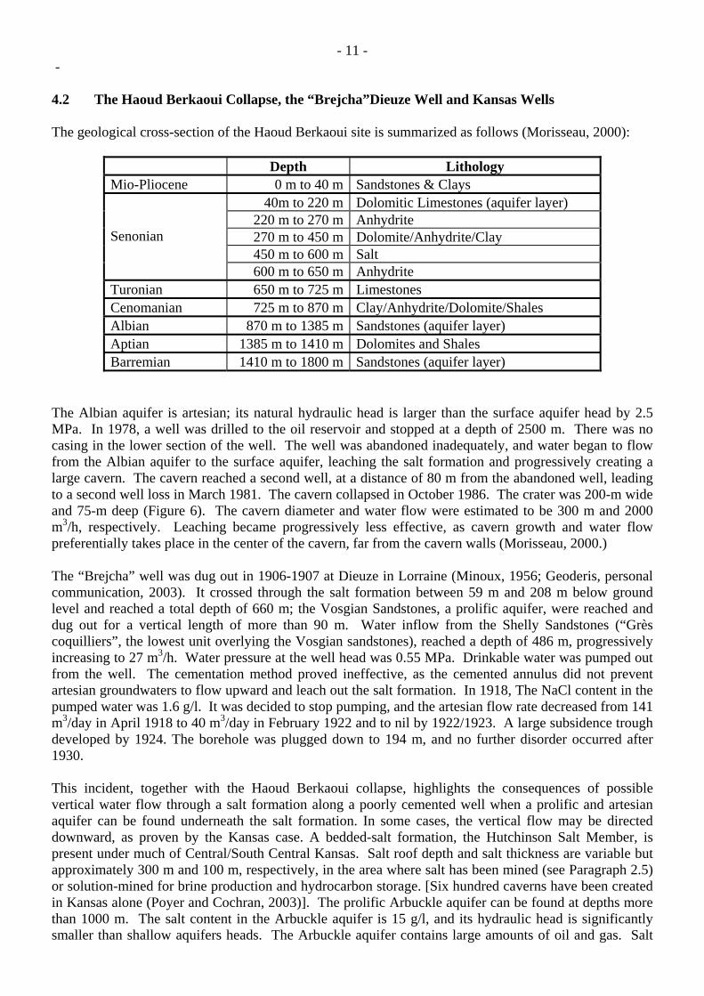
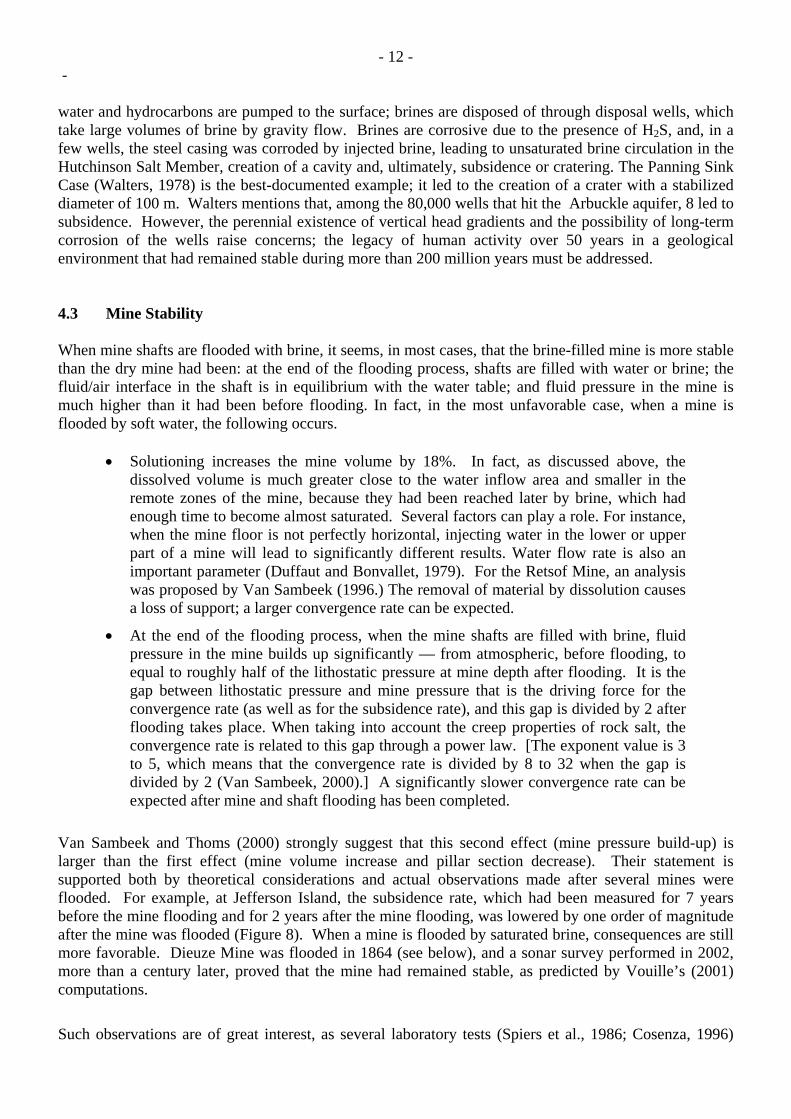
- 11 - - 4.2 The Haoud Berkaoui Collapse, the “Brejcha”Dieuze Well and Kansas Wells The geological cross-section of the Haoud Berkaoui site is summarized as follows (Morisseau, 2000):
Depth Lithology Mio-Pliocene 0 m to 40 m Sandstones & Clays
40m to 220 m Dolomitic Limestones (aquifer layer) 220 m to 270 m Anhydrite 270 m to 450 m Dolomite/Anhydrite/Clay 450 m to 600 m Salt
Senonian
600 m to 650 m Anhydrite Turonian 650 m to 725 m Limestones Cenomanian 725 m to 870 m Clay/Anhydrite/Dolomite/Shales Albian 870 m to 1385 m Sandstones (aquifer layer) Aptian 1385 m to 1410 m Dolomites and Shales Barremian 1410 m to 1800 m Sandstones (aquifer layer)
The Albian aquifer is artesian; its natural hydraulic head is larger than the surface aquifer head by 2.5 MPa. In 1978, a well was drilled to the oil reservoir and stopped at a depth of 2500 m. There was no casing in the lower section of the well. The well was abandoned inadequately, and water began to flow from the Albian aquifer to the surface aquifer, leaching the salt formation and progressively creating a large cavern. The cavern reached a second well, at a distance of 80 m from the abandoned well, leading to a second well loss in March 1981. The cavern collapsed in October 1986. The crater was 200-m wide and 75-m deep (Figure 6). The cavern diameter and water flow were estimated to be 300 m and 2000 m3/h, respectively. Leaching became progressively less effective, as cavern growth and water flow preferentially takes place in the center of the cavern, far from the cavern walls (Morisseau, 2000.) The “Brejcha” well was dug out in 1906-1907 at Dieuze in Lorraine (Minoux, 1956; Geoderis, personal communication, 2003). It crossed through the salt formation between 59 m and 208 m below ground level and reached a total depth of 660 m; the Vosgian Sandstones, a prolific aquifer, were reached and dug out for a vertical length of more than 90 m. Water inflow from the Shelly Sandstones (“Grès coquilliers”, the lowest unit overlying the Vosgian sandstones), reached a depth of 486 m, progressively increasing to 27 m3/h. Water pressure at the well head was 0.55 MPa. Drinkable water was pumped out from the well. The cementation method proved ineffective, as the cemented annulus did not prevent artesian groundwaters to flow upward and leach out the salt formation. In 1918, The NaCl content in the pumped water was 1.6 g/l. It was decided to stop pumping, and the artesian flow rate decreased from 141 m3/day in April 1918 to 40 m3/day in February 1922 and to nil by 1922/1923. A large subsidence trough developed by 1924. The borehole was plugged down to 194 m, and no further disorder occurred after 1930. This incident, together with the Haoud Berkaoui collapse, highlights the consequences of possible vertical water flow through a salt formation along a poorly cemented well when a prolific and artesian aquifer can be found underneath the salt formation. In some cases, the vertical flow may be directed downward, as proven by the Kansas case. A bedded-salt formation, the Hutchinson Salt Member, is present under much of Central/South Central Kansas. Salt roof depth and salt thickness are variable but approximately 300 m and 100 m, respectively, in the area where salt has been mined (see Paragraph 2.5) or solution-mined for brine production and hydrocarbon storage. [Six hundred caverns have been created in Kansas alone (Poyer and Cochran, 2003)]. The prolific Arbuckle aquifer can be found at depths more than 1000 m. The salt content in the Arbuckle aquifer is 15 g/l, and its hydraulic head is significantly smaller than shallow aquifers heads. The Arbuckle aquifer contains large amounts of oil and gas. Salt
- 12 - - water and hydrocarbons are pumped to the surface; brines are disposed of through disposal wells, which take large volumes of brine by gravity flow. Brines are corrosive due to the presence of H2S, and, in a few wells, the steel casing was corroded by injected brine, leading to unsaturated brine circulation in the Hutchinson Salt Member, creation of a cavity and, ultimately, subsidence or cratering. The Panning Sink Case (Walters, 1978) is the best-documented example; it led to the creation of a crater with a stabilized diameter of 100 m. Walters mentions that, among the 80,000 wells that hit the Arbuckle aquifer, 8 led to subsidence. However, the perennial existence of vertical head gradients and the possibility of long-term corrosion of the wells raise concerns; the legacy of human activity over 50 years in a geological environment that had remained stable during more than 200 million years must be addressed. 4.3 Mine Stability When mine shafts are flooded with brine, it seems, in most cases, that the brine-filled mine is more stable than the dry mine had been: at the end of the flooding process, shafts are filled with water or brine; the fluid/air interface in the shaft is in equilibrium with the water table; and fluid pressure in the mine is much higher than it had been before flooding. In fact, in the most unfavorable case, when a mine is flooded by soft water, the following occurs.
• Solutioning increases the mine volume by 18%. In fact, as discussed above, the dissolved volume is much greater close to the water inflow area and smaller in the remote zones of the mine, because they had been reached later by brine, which had enough time to become almost saturated. Several factors can play a role. For instance, when the mine floor is not perfectly horizontal, injecting water in the lower or upper part of a mine will lead to significantly different results. Water flow rate is also an important parameter (Duffaut and Bonvallet, 1979). For the Retsof Mine, an analysis was proposed by Van Sambeek (1996.) The removal of material by dissolution causes a loss of support; a larger convergence rate can be expected.
• At the end of the flooding process, when the mine shafts are filled with brine, fluid pressure in the mine builds up significantly — from atmospheric, before flooding, to equal to roughly half of the lithostatic pressure at mine depth after flooding. It is the gap between lithostatic pressure and mine pressure that is the driving force for the convergence rate (as well as for the subsidence rate), and this gap is divided by 2 after flooding takes place. When taking into account the creep properties of rock salt, the convergence rate is related to this gap through a power law. [The exponent value is 3 to 5, which means that the convergence rate is divided by 8 to 32 when the gap is divided by 2 (Van Sambeek, 2000).] A significantly slower convergence rate can be expected after mine and shaft flooding has been completed.
Van Sambeek and Thoms (2000) strongly suggest that this second effect (mine pressure build-up) is larger than the first effect (mine volume increase and pillar section decrease). Their statement is supported both by theoretical considerations and actual observations made after several mines were flooded. For example, at Jefferson Island, the subsidence rate, which had been measured for 7 years before the mine flooding and for 2 years after the mine flooding, was lowered by one order of magnitude after the mine was flooded (Figure 8). When a mine is flooded by saturated brine, consequences are still more favorable. Dieuze Mine was flooded in 1864 (see below), and a sonar survey performed in 2002, more than a century later, proved that the mine had remained stable, as predicted by Vouille’s (2001) computations.
Such observations are of great interest, as several laboratory tests (Spiers et al., 1986; Cosenza, 1996)
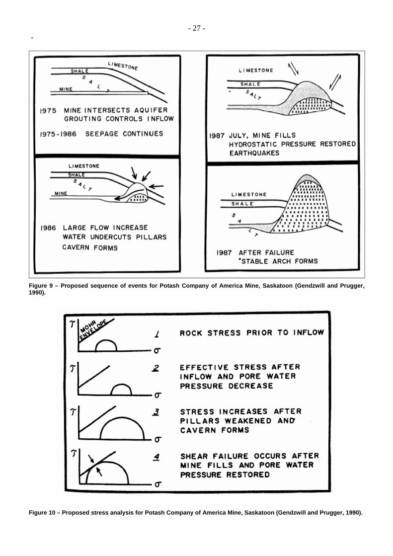
- 13 - - suggest the opposite: the creep rate of a loaded sample considerably accelerates when saturated brine is added around the sample. Such a phenomenon does not seem to affect mine pillars, probably because it is a “skin” effect. (It is effective inside a few cm-deep zone behind the salt wall — a significant depth for a sample, but not for a mine pillar.) According to Van Sambeek and Thoms (2000), it must be noted that, even if the subsidence rate above a flooded mine were lowered, the ultimate evolution of the mine remains the same: mine closure will be completed after some time, but, in most cases, the final evolution occurs over several dozens of centuries — a time period that is too long to be of practical significance. It must also be noted that creation of new voids through solutioning starts as soon as soft water enters the mine; however, stabilization of the mine by pressurized brine is effective only at the end of the process, when shaft filling with brine is completed; the filling period is most critical. 4.4 Monitoring One additional advantage of mine filling is that injection rate and location can be selected before deliberate flooding; if there are adverse consequences (discussed later), they will appear at a time when the mine and its environment can be monitored carefully and mitigating measures can be taken rapidly. 5 DISADVANTAGES OF MINE FLOODING 5.1 Post-Abandonment Fluid Movement Brine movements generated by non-uniform hydraulic heads in surrounding water-bearing strata have been considered (above). 5.2 High Effective Pressure in Porous Layers Undamaged salt is a very impermeable rock, for which the notion of an "effective" stress (i.e., total stress minus pore fluid pressure) is not likely to be relevant, as it is in the context of reservoir engineering. The same cannot be said of other rocks that are crossed by galleries and shafts. In such a case, mine flooding may have negative consequences in that it generates pore pressure build-up. In 1986, at the Potash Company of America Mine at Esterhazy (Canada), the mining works crossed the “second red bed shale”, a layer that is situated, generally, 20 m above the salt roof and below the prolific Dawson Bay aquifer (Figure 9). The water flow increased, and the mine began to collapse. A decision was made to abandon the mine by January 1987; flooding was expected to be completed by July 1987. On July 1-2, cracks began to be heard, increasing progressively in number and magnitude. Gendzwill and Prugger (1990) attribute these seismic events to restoring of fluid pressure in the overlying limestones (Figure 10), a direct consequence of mine flooding. Such seismic events induced by high-pressure fluid injection are observed frequently in oil fields or during the filling of large dams.

- 14 - - 5.3 Presence of Non-Halitic Evaporites Magnesium salts (carnallite, bischofite, kieserite, etc.) are much more soluble in water than is halite. When a mine contains such salts, preferential dissolution can occur in the areas of the mine where they are present, leading to a local volume increase far greater than the average (i.e., at the full-mine scale) volume increase. Such a case is frequent in the German Zechstein domes. Injecting NaCl-saturated brine in the mine will not prevent any problem: Natrium Chloride will crystallize, but more soluble salts will be leached, generating brine convection in the mine to restore chemical and mechanical equilibrium. Such phenomena have been discussed by Wilhelm et al. (2002). Flooding of a potash mine by halite brine and its induced structural damage from the dissolution of sylvite-carnallite are described in Van Sambeek (1993). 5.4 Weathering of Marly Rocks As noted in the introduction, there often exist large volumes of pure salt in salt domes: non-halitic minerals do not play a significant role in the mechanical behavior of a domal salt mine. The same cannot be said for bedded salt formations, which contain numerous marly or anhydritic interbedded layers. Quite often, mining voids are created in a salt layer located between two non-halitic layers; a salt slab sometimes is left at the mine floor and/or roof, but, in some places, direct contact often exists between the mine atmosphere and the non-halitic layers. When a mine is flooded, these layers may come into contact with brine eventually. It is well known that marly or clayey rocks can weather considerably if they are in contact with water or brine. This phenomenon is of utmost importance for mine stability and is discussed in more detail in the next section. However, somewhat similar weathering may occur in interbedded clayey or marly layers at the mine floor. One example of this, the events before the Varangéville 1873 collapse, is described below (Paragraph 6.2.) 6.0 WEATHERING OF MARLY LAYERS 6.1 Lessons Drawn from Brine Field Operation When discussing weathering of marls in dry mines, lessons can be drawn from the behavior of salt caverns in the same geological formation, if several obvious differences are kept in mind. Stress distribution plays a significant role when rock weathering is concerned. In caverns, wide roof spans are the main concern; in dry mines, the fraction of the overburden weight that is supported by the pillars and the ability of the pillars, roof and floor to withstand this additional load are the main mechanical problems. It is well known that weathering takes place when a cavern roof reaches the claystone or marly layers overlying the salt formation. The cavity migrates upward because of the collapse of roof layers. Such a migration is observed in the Hengelo Brine Field in the Netherlands. Bekendam et al. (2000) lists the various physico-chemical effects that, together with stress development in the roof, contribute to claystone collapse. Similar phenomena, including slow vertical roof rise in the non-halitic strata, are described by Buffet (1998) for the Gellenoncourt SG4 and SG5 caverns in Lorraine. These two caverns unintentionally coalesced, and the large resulting cavern reached the roof of the salt formation, allowing direct contact between the marly roof and the cavern brine. By 1982, the roof span at the brine-marl interface was 50-m wide. From 1982 to 1992, the system was isolated (No water was injected.), and only minor roof failure was observed. (In 1986, the roof was 213-m deep, or 4 m higher than the salt-marl interface; it was 209-m deep in 1990.) After this initial phase, roof rise accelerated: the roof depth was 172 m by October 1992 and 146 m by 1993. Eventually, the roof reached the stiff and competent Beaumont Dolomite layer, and roof progression stopped. Long-term stability of the cavern could not be
- 15 - - taken for granted, and it was decided to collapse the cavern. As described above, brine pressure in the cavern was lowered to atmospheric, but this move was not sufficient to lead to roof layer collapse. The cavern was enlarged through solution-mining, and collapse eventually was obtained in 1992 . Such a roof migration is not expected in the case of a room-and-pillar mine, unless the mine experiences partial collapse before abandonment, because a large salt slab, protecting the overlying strata, is often left at the mine roof. However, roof floor may be a concern. 6.2 The 1873 Varangéville Mine Collapse Part of the Varangéville salt mine collapsed in 1873, and its collapse illustrates the possible adverse effects of water on salt mine floor (Archives CSMSE). The mine was opened at the base of the third unit of the Lower Keuper Salt Formation, also called the 11th layer, which is 17-m to 20-m thick in this area. The main galleries were 9-m wide with an initial height of 5.5 m. The perpendicular galleries were 8-m wide, and the squared pillars were 6-m wide. The theoretical extraction ratio was 82%, but the actual ratio was probably higher. The mining objective was to extract both rock salt and brine. Explosives were used, but part of the salt was removed through solution mining. Three vertical cuts were created before the gallery face was blasted. After a time, it was decided to cut 3 vertical slots using pressurized water. The cuts were 30-cm to 40-cm wide and 3-m deep. The resulting brine was collected in a pool and brought to saturation. After the decision to increase brine production, galleries were made 17-m high instead of 5.5-m high. A mobile scaffolding bearing 18 iron tubes provided a water flow of 1.5 m3/h. The flow ran down the gallery face and dissolved the rock salt. The unsaturated brine was collected and transferred to the mine shaft through wooden gutters. Much brine was lost because gutters leaned or were obstructed by marly slurry. This brine seeped into the floor, dissolved salt seams and veins, hydrated the anhydrite and oxidized the pyrite — all leading to weakening of the floor rock. The effect of clay swelling may also be of importance in this context. Five years before the mine collapsed, fissures appeared in the pillars near the shaft, and gutters dug out in mine floor experienced rapid closure; in the Saint Julie gallery, the mine floor heaved by 80 cm. Vertical fractures, 5-cm wide, running from pillar top to bottom, were clearly visible. In October 1873, large subsidence was observed at ground level above the mine. On October 31, at 5 a.m., a fissure developed in a building, and the zone was evacuated. It was reported that the collapse took less than two seconds. Numerous fractures opened at ground level; they were located on two concentric ellipses, almost circular, 160-m and 350-m in diameter, respectively. Crests were observed inside the inner ellipse, a clear sign of compressive horizontal stresses in this circle. Inside the mine, all pillars closer than 80 m from the shaft had punctured the mine floor. Although fractures were apparent at ground level and subsidence of more than 3 m was observed, no water entered the mine, which remained dry (and is still dry) in this area. At the time, miners believed that the accident was caused by floor weathering, a consequence of unsaturated brine seepage into the floor. When the softening zone propagated below the pillars, the pillars no longer could be supported by the floor, resulting in the collapse of the mine. This explanation seems at least partly correct, as such weathering currently is observed in this mine. However, this explanation is questioned by some experts. The high extraction ratio (probably higher than the theoretical 82%) is considered as an alternative (or at least additional) explanation. When the mine became big enough, the “critical width” was reached, and the shear stresses above the mine edges were large enough to generate mine collapse. According to these more recent views, the puncturing of
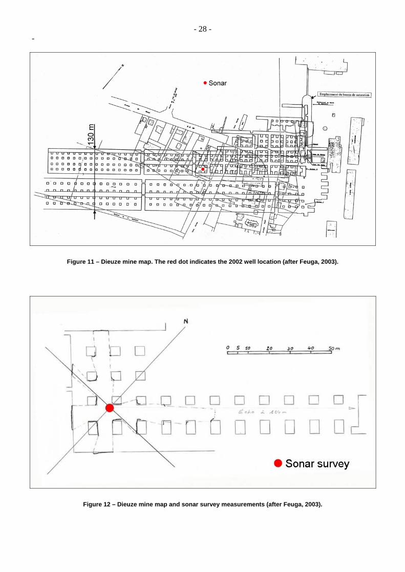
- 16 - - the floor was a secondary consequence of cratering. Floor weathering may have been instrumental in this context, but it would not be the primary cause of mine collapse. 6.3 The 1864 Dieuze Mine Flooding The Dieuze Mine had been in operation for 38 years when it was flooded in 1864 (Feuga, 2003). Two panels had been opened, each 65 m x 550 m, separated by a 10-m x 550-m central pillar (Figure 11). Each panel had been mined by a mine-and-pillar method: pillars were (4.5-m to 5-m) x (4.5-m to 5-m), and galleries were 6-m to 9-m wide. The resulting extraction ratio was 80% to 90%. The mine, implemented in the 11th layer (i.e., at the base of the third unit of the Lower Keuper Salt Formation), was 3.75-m to 4-m high, and the roof depth was approximately 115 m. A salt slab, 1.3-m thick, was left at the mine roof. Salt pillars rested directly on a claystone layer. (No salt slab was left at mine ceiling.) The salt content in the overburden is 67%. Insolubles include clay and anhydrite. The salt roof in this area is at a depth of 50 m. The mine floor is composed of argillite and anhydrite, with a small amount of halite. A gallery, opening into the mine shaft, had been dug at a depth of 60 m (i.e., below the salt roof), and a saturated brine pool was created in this gallery. On February 8, 1864, this gallery collapsed, leading to rapid flooding of the gallery by brine flowing down from the brine aquifer at the salt formation roof. Saturated brine rushed down the mine shaft, flooding the mine 60 m below. In March 1864, the brine flow was estimated to be 430 m3/h, and the mine was abandoned. For more than a century, no further evolution was observed. In 2002, Geoderis, a state agency, decided to drill a borehole to the mine. The borehole, and the sonar survey performed after the well hit the mine, proved that the mine had been preserved perfectly. The map drawn after the sonar survey measurements almost exactly matches the 140-year-old map drawn by the miners. Within an accuracy of a few centimeters, the measured mine height had not changed. Concerns had been expressed that salt pillars and/or clayey mine floors could have been weakened severely after having been kept in direct contact with saturated brine. (Such alteration of the marly layers below the floor of the somewhat similar Varangéville Mine has been observed frequently.) No such alteration can be inferred from the sonar survey results. The floor is perfectly flat, the mine height remains unchanged, and the mine appears to be perfectly stable, even if the extraction ratio is relatively high. (At 115 m, the overburden pressure is 2.5 MPa. If this overburden weight were fully transmitted to the pillars, the average load on the pillars would be 20 MPa; such a mechanical loading should have generated relatively high convergence rates before mine flooding. In fact, according to Vouille (2001), it is believed that the roof behaved as a thick, stiff, competent layer that allowed transfer of a large part of the overburden weight to the surrounding salt body.) Weathering of the argilitic floor and punching of the floor by overweighted pillars, an event feared after the 1873 Varangéville collapse, clearly did not take place in the Dieuze Mine (Feuga, 2003). 6.4 Conclusions The Dieuze and Varangéville cases lead to somewhat different conclusions with regard to floor behavior. In the Dieuze case, no floor weathering took place — even after 140 years of direct contact between the floor and saturated brine. The Varangéville case is less clear: floor weathering is observed currently in the mine, and it may have played some role in the 1873 collapse. Considering both cases, even if the floor is located in the same horizon (the base of the 11th layer, or third unit), the mineralogical composition of the rock in the two mines may differ. However, geologists (Rouchy and Blanc-Valleron, personal communication) state that these differences may not be significant.
- 17 - - The weathering of marly rocks, in the context of salt mines and caverns, has not yet been fully studied (Studies performed by Ecole des Mines de Paris have proven that marl samples from the Varangéville Mine lose strength when in contact with brine.) It is commonly observed that marls weather when in contact with brine, water or air. However, little scientific information is available, making any precise conclusion difficult. A few general comments can be made:
1. By itself, contact between brine and marls (or argillites) is probably not enough to generate fast progression of a weathered zone. Tensile stresses or high compressive stresses, resulting from a wide roof span (in a cavern) or from a high extraction ratio (in a dry mine), must also be present, as outlined by Walters (1978) and Bekendam et al. (2000).
2. Whether poro-mechanical effects play a role is still unclear. When brine is in contact with a marl layer, in a cavern, brine permeates through the marls, as its pressure is likely to be larger than the natural pore pressure of marls. Brine flows through the natural pores of the rock, but perhaps also through micro-cracks opened (in cavern roofs) by tensile stresses. Flow can also be driven by salinity gradients. These phenomena are diffusive in nature and can explain why weathering is a slow process. Weathering generally is attributed to chemical mechanisms; however, effective stresses change due to pore pressure build-up provides an alternative explanation (see Paragraph 5.2).
3. The effect of brine saturation is equivocal. Walters (1978), with respect to the Kansas case, describes the effect of soft water or unsaturated brine dissolving halite veins filling cracks inside the marly layers. Bekendam et al. (2000), along with several observations made in Lorraine, suggest that some chemical effects (still to be identified) are quite active when saturated brine is in contact with marly layers. Other experts think that argillite weathering is due to the presence of a small amount of salt that attracts soft water, leading to clay swelling: saturated brine (Dieuze) should have no weathering effect, in sharp contrast with unsaturated brine (Varangéville).
4. Sampling, when performed with no special care, results in rock deconfinement, desaturation, oxidation, or even in bacterial activity — all of which lead to severe disturbances. Conclusions drawn from laboratory tests can be misleading.
5. The layers that compose the mine roof or floor, or the salt formation roof, must be considered as a composite system. The salt or anhydrite layers are much stronger than the marly layers; they can only be broken by intense mechanical loading. Failure of these layers strips weaker layers, which are rapidly weathered through the action of water or brine. These differences may explain the sharp contrast in the behavior of two neighboring mines or the "stop-and-go" process that is observed when cavern roof rises in a non-halitic formation.
Mechanisms leading to the weathering of floor or roof layers in a salt mine still are not well understood. In this context, deliberate flooding of dry mines, a reasonable option for domal salt formations, is a matter of controversy when considering bedded salt formations.
- 18 - - 7. CONCLUSIONS As mentioned above, when a dry mine located beneath an inhabited area must be abandoned, several options can be considered:
(1) intentional mine collapse;
(2) filling the mine with debris;
(3) filling the mine with brine or water; and
(4) indefinite mine monitoring.
The authors believe that dry mine filling (with brine or soft water), which is mandatory in Northern Germany salt domes, is the first option to be considered, even for bedded salt formations. However, the existence of non-halitic layers at the mine floor may induce adverse effects that must be considered thoroughly. ACKNOWLEDGEMENTS The authors are indebted to many colleagues who provided them with comments and data: the members of the International Expert Group (IEG) commissioned by the French Mining Regulatory Authorities, B. Diamond, A. Duquesnoy, G. Durup, L. Lohff; and A. Buffet whose knowledge of Lorraine geology has been extremely helpful. Bibliographic suggestions have been received from I. Salpeteur. L. Van Sambeek and A. Kunstman kindly provided the authors with (unpublished) data concerning the Kanopolis and Wapno cases, respectively. The bibliographic study was supported partly by Geoderis, a French governmental agency. Special thanks to K. Sikora. REFERENCES Archives CSMSE - “Note sur l’accident de 1873 à la mine de Varangéville”. Varangéville Archives d’exploitation de la Compagnie des Salins du Midi et des Salines de l’Est (“A note on the Varangéville Mine Accident”, in French, unpublished.) Bauer S.J., Ehgartner B.L., Neal J.T. (2000) - “Geotechnical Studies Associated with Decommissioning the Strategic Petroleum Reserve Facility at Weeks Island, Louisiana : A Case History”. Proc. Technical Class and Technical Session SMRI Fall Meeting, San Antonio, p. 146-156. Bekendam R., Oldenziel C., Paar W. (2000) – “Subsidence Potential of the Hengelo Brine Field (Part I). Physico-Chemical Deterioration and Mechanical Failure of Salt Cavern Roof Layers”. Proc. Technical Class and Technical Session SMRI Fall Meeting, San Antonio, p. 103-118. Buffet A. (1998) - “The collapse of Compagnie des Salins SG4 and SG5 drillings”. Proc. SMRI Fall Meeting, Roma, p. 79-105. Buffet A., Hilly J., Marchal C. (1993) – “Relationship between the Composition of Raw Brines Originating from the Mining of Lorraine Salt rock (NE France) and the Lithology of the Deposit”. Proc. 7th Symp. on Salt, Kyoto, H. Kakihana, H.R. Hardy Jr, T. Hoshi, K. Toyokura eds., Elsevier, Vol. I, p.195-204.
- 19 - - Carosella M.E. (1978) - “The Use of Salt Domes for the Strategic Petroleum Reserve”. Proc. 5th Symp. on Salt , A.H. Coogan and L. Hauber ed., Northern Ohio Geological Society Inc. Pub., Vol. II, p. 69-75. Cosenza P. (1996) - “Sur les couplages entre comportement mécanique et processus de transfert de masse dans le sel gemme“. Thèse de l'Université Paris VI, Spécialité Mécanique (« Coupling between Mechanical Behavior and Mass Transfer in Rock Salt », PhD Thesis, Paris VI University, in French.) DARPMI (2001) Direction de l’Action Régionale et de la Petite et Moyenne Industrie, Ministère de l’Economie et des Finances – « L’après-mine de sel en France », Rapport interne, Février 2001 (“Post Salt-Mining in France”, Internal Report, February 2001, in French.) Duffaut P., Bonvallet J. (1979) - “Mine de sel de Varangéville. Poursuite de l'exploitation dans la concession Rhône-Poulenc”. Rapport BRGM pour le Ministère de l'Industrie. 79 SGN 708 GEG. (A BRGM Report, prepared for the French Ministry of Industry, in French, unpublished.) Feuga B. (2003) - “Old salt mine at Dieuze (France) revisited 150 years after being abandoned”. Submitted for publication in Proc. SMRI Fall Meeting, Chester. Gendzwill D.J., Prugger F.F. (1990) - “Seismic activity in a flooded Saskatchewan potash mine”. In C. Fairhurst, editor, Proc. 2nd Int. Symp. on Rockbursts and Seismicity in Mines, Minneapolis, 8-10 June 1988, Balkema, Rotterdam, p. 115-120. Gowan S.W., Trader S.M., Van Sambeek L.L. (1999) - “The discovery of an apparent brine pool associated with anomalous closure patterns and the eventual failure of the Retsof salt mine”. Proc. S.M.R.I. Fall Meeting, Washington DC, p. 241-272. Gowan S.W., Trader S. (2000) - “The mechanism of sinkhole formation above the collapse of a small yield-pillar panel in the Retsof salt mine”. Proc. Technical Class and Technical Session, SMRI Fall Meeting, San Antonio, p. 313-332. Griffith A.E. (1991) - “Tennant’s ills”. Ground Engineering, November 1991, p.18-21 Hoffman E.L., Ehgartner B.L. (1997) - “Using Three Dimensional Structural Simulations to Study the Interactions of Multiple Excavations in Salt”, SAND 97-1017C Report, Sandia National Laboratories, Albuquerque, N.M. Jeremic M.L. (1994) - “Rock Mechanics in Salt Mining”. A.A. Balkema, Rotterdam, 532 pages. Johnson K.S., Gonzales S. (1978) – “Salt deposits in the United States and Regional Geological Characteristices Important for Storage of Radioactive Waste”, Y/OWI/SUB-7414/1 Report, Office of Waste Isolation (OWI), US-DOE, Earth Resource Associates, Inc., Athens, GA, p. 60. Johnston K.S. (2001) - “Sinkholes associated with Petroleum Boreholes Drilled Through Salt Deposits in the USA”. Proc. SMRI Fall Meeting, Albuquerque, p.8-17. Kunstman A.S., Urbanczyk K.M. (2003) - “Catastrophic flooding of Wapno salt Mine (1977) and controlled flooding of Solno Mine (1986-1991) – reasons, circumstances, consequences”. To be published in the Proc. SMRI Fall Meeting, Chester. Kupfer D.H. (1980) - “Problems associated with Anomalous Zones in Louisiana Salt Stocks, USA”. Proc. 5th Symp. on Salt, Hamburg, May-June 1979, The Northern Ohio Geological Society, Inc., Vol. II, p. 119-134.

- 20 - - Lolan W.E., Valadie R.J., Ballou P.J. (1998) - “Remote Operated Vehicle (ROV) Design, Cavern Survey and Gel Plugging Agent Application to Repair Louisiana Offshore Oil Port (LOOP) Cavern 14”. Proc. SMRI Fall Meeting, Roma, p. 327-345. Maas K. (2001) - “Analysis, Modelling and Simulation of recent Subrosion in a flooded Potash Shaft”. Proc. SMRI Fall Meeting, Albuquerque, p. 272-281. McCauley T.V., Ratigan J.L., Sydansk R.D., Wilson S.D. (1998) - “Characterization of the Brine Loss Zone and Development of a Polymer Gel Plugging Agent to Repair Louisiana Offshore Oil Port (LOOP) Cavern 14”. Proc. SMRI Fall Meeting, Roma, p. 391-406. Minoux G. (1956) - “Programme technique pour l’exécution d’un forage AEP de l’Usine Kuhlman”. Rapport BRGM A 938 (Technical Program for an AEP well drilling in the Kuhlman factory, in French, unpublished). Morisseau J.M. (2000) - “Uncontrolled leaching of salt layer in an oil field in Algeria”. Proc. Technical Class and Technical Session, SMRI Fall Meeting, San Antonio, p. 330-333 Nichols N.W, Wu K.K., Kravitz J.H., O’Gorman F.E., Risbeck J.S., Durfee J.W., Wilcox W.R., Feehan R.D., Lilly D.P. (1981) - “The Jefferson Island Mine Inundation, November 20, 1980”. Mine Safety and Health Administration, U.S. Department of Labor, Report n° 202 031 (131 p.) O'Gorman F., Stafford S. (1980) - “Jefferson Island: when courage, training, saved 52 in mine flood”. Mine Safety and Health Administration, U.S. Department of Labor, Report n° 205 957 (6 p.) Payment K.A. (2000) - “Loss of the Retsof salt mine: legal analysis of liability issues”. In R.M. Geertma, editor, Proc. 8th World Salt Symp., Salt 2000, The Hague, Pays-Bas, Elsevier Science publishers B.V., Amsterdam, Vol. I, p. 399-404. Poyer C., Cochran M. (2003) - “Kansas Underground Storage Regulations”. Proc. SMRI Fall Meeting, Houston, p.199-204. Prugger F.F. (1980) - “The flooding of the Cominco potash mine and its rehabilitation”. Proc. 5th Symp. on Salt, Hamburg, May-June 1979, The Northern Ohio Geological Society, Inc., Vol. I, p. 333-340. Rölleke F.J. (2000) - “Subsidence and Sinkholes over Flooded Potash Mines in Northern Germany”. Proc. Technical Class and Technical Session, SMRI Fall Meeting, San Antonio, p. 87-101. Spiers C.J., Urai J.L, Lister G.S., Boland J.N., Zwart H.J. (1986) - “Long-term rheological and transport properties of dry and wet salt rocks” Final Report, Commission of the European Communities, EUR 11848. Thoma H., Seifert G., Kuehn F. (2000) - “Examples of the Development of Sinkholes above Flooding or Flooded Salt Mines in Central Germany and Ways of Remote Detection of Areas with a Potential Risk of Fall”. Proc. Technical Class and Technical Session, SMRI Fall Meeting, San Antonio, p. 163-184. Thoms R.L., Gehle R.M. (1994) - “The Jefferson Island mine flooding revisited”. SMRI Spring Meeting, Houston. Thoms R.L., Gehle R.M (2000) - “Winnfield mine flooding and collapse event of 1965”. Proc. Technical Class and Technical Session, SMRI Fall Meeting, San Antonio, p. 262-274.
- 21 - - Van Sambeek L.L. (1996) - “Dissolution-induced mine subsidence at the Retsof salt mine”. Proc. SMRI Fall Meeting, Cleveland, p. 289-309. Van Sambeek L., Thoms R. (2000) - “Pre- and Post-Flooding Surface Subsidence Rates at the Retsof, Belle Isle, Jefferson Island Salt Mines”. Proc. Technical Class and Technical Session, SMRI Fall Meeting, San Antonio, p. 75-85. Van Sambeek L.L. (1993) - “The IMC K2 Mine Flooding”. SMRI Fall Meeting, La Fayette. Van Sambeek L. (2000) - “Subsidence Modeling and the use of the SMRI SALT_SUB SID Software”. Proc. Technical Class and Technical Session, SMRI Fall Meeting, San Antonio, p. 11-22. Van Sambeek L.L., Gowan S.W., Payment K.A. (2000) - “Loss of the Retsof salt mine: Engineering analysis”. In R.M. Geertman ed., Proc. 8th World Salt Symposium, Salt 2000, The Hague, Netherlands, Elsevier Science Pub. B.V., Amsterdam, Vol. I, p. 411-416. Vouille G. (2001) - Communication to the GEODERIS Salt Expert Group. Walters R.F. (1978) - “Land subsidence in Central Kansas Related to Salt Dissolution”. Kansas Geological Survey Bull. 214, p.1-81. Wilhelm St., Poppei J., Mayer G., Schwarz R., Klubertanz G., Siegel P., Förster B. (2002) - “Influence of chemical reactions on the flow system and contaminant transport in a former salt mine”. Proc. Int. Conf. Uranium Mining and Hydrogeology III. Friberg Sept. 2002.
- 22 - -
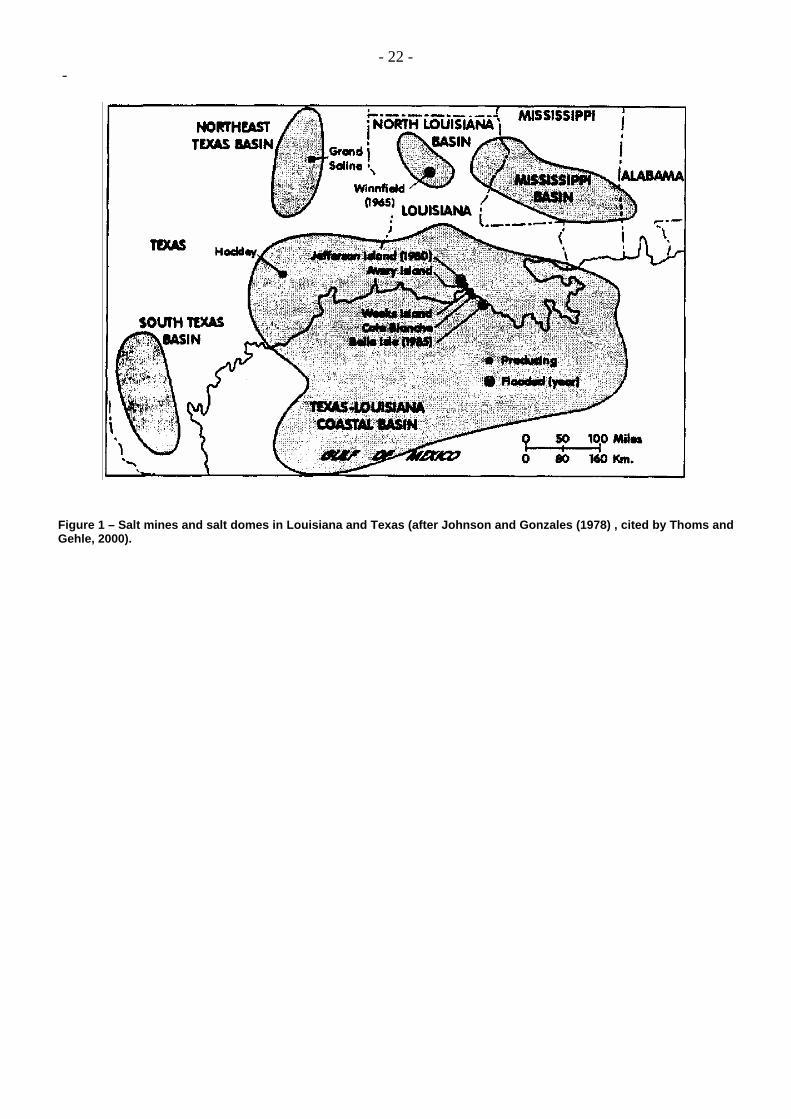
Figure 1 – Salt mines and salt domes in Louisiana and Texas (after Johnson and Gonzales (1978) , cited by Thoms and Gehle, 2000).
- 23 - -
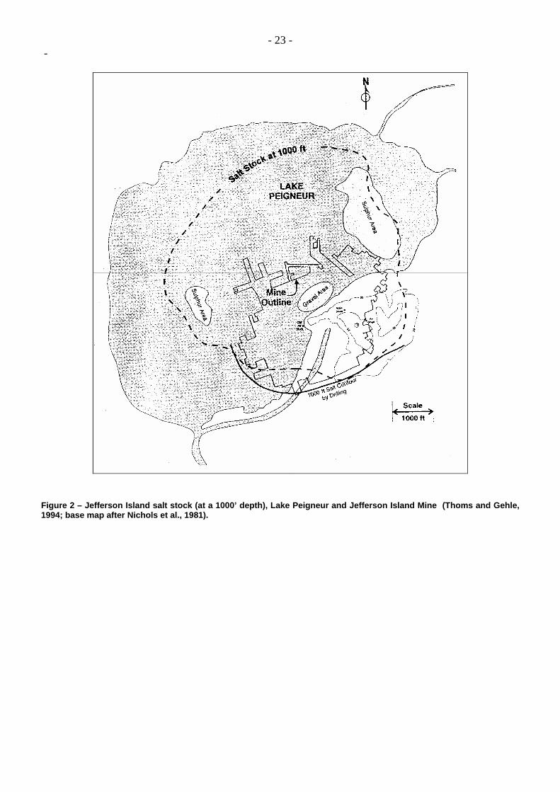
Figure 2 – Jefferson Island salt stock (at a 1000’ depth), Lake Peigneur and Jefferson Island Mine (Thoms and Gehle, 1994; base map after Nichols et al., 1981).
- 24 - -
Figure 3 – Weeks Island Mine. [The mine was converted into an oil storage. Geomechanical modeling by Hoffman and Ehgartner (1997) showed mechanism for crack development in tension that would develop over mined openings after a number of years and progress through weakened dilatant zones (after Bauer et al., 2000).]
Figure 4 –Vertical cross-section of the Ronnendorf salt dome (Rölleke, 2000).
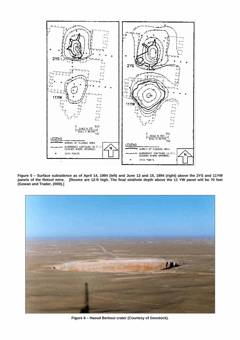
Figure 5 – Surface subsidence as of April 14, 1994 (left) and June 13 and 15, 1994 (right) above the 2YS and 11YW panels of the Retsof mine. [Rooms are 12-ft high. The final sinkhole depth above the 11 YW panel will be 70 feet (Gowan and Trader, 2000).]
Figure 6 – Haoud Berkoui crater (Courtesy of Geostock).
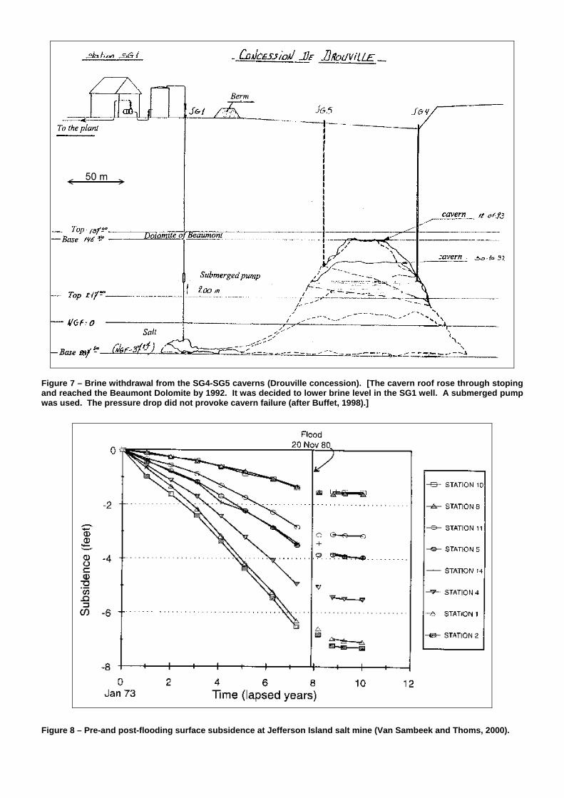
Figure 7 – Brine withdrawal from the SG4-SG5 caverns (Drouville concession). [The cavern roof rose through stoping and reached the Beaumont Dolomite by 1992. It was decided to lower brine level in the SG1 well. A submerged pump was used. The pressure drop did not provoke cavern failure (after Buffet, 1998).]
Figure 8 – Pre-and post-flooding surface subsidence at Jefferson Island salt mine (Van Sambeek and Thoms, 2000).
- 27 - -
Figure 9 – Proposed sequence of events for Potash Company of America Mine, Saskatoon (Gendzwill and Prugger, 1990).
Figure 10 – Proposed stress analysis for Potash Company of America Mine, Saskatoon (Gendzwill and Prugger, 1990).
- 28 - -
Figure 11 – Dieuze mine map. The red dot indicates the 2002 well location (after Feuga, 2003).
Figure 12 – Dieuze mine map and sonar survey measurements (after Feuga, 2003).