dryden centerwide procedure code s pressure vessels ... · 9.0 welding operations on pvs ... c....
TRANSCRIPT

Before use, check the Master List to verify that this is the current version. This document may be distributed outside of Dryden.
Dryden Flight Research Center DCP-S-065, Baseline-2 Edwards, California 93523 Expires January 11, 2015
Dryden Centerwide Procedure
Code S
Pressure Vessels & Pressurized Systems Safety
(With changes 07-26-11.) Electronically approved by Assistant Director for Management Systems
Pressure Vessels & DCP-S-065, Baseline-2 Pressurized Systems Safety Expires January 11, 2015 Page 2 of 35
Before use, check the Master List to verify that this is the current version. This document may be distributed outside of Dryden.
CONTENTS 1.0 PURPOSE OF DOCUMENT ................................................................................. 4
2.0 PROCEDURE SCOPE & APPLICABILITY ............................................................ 4
3.0 OBJECTIVES & METRICS .................................................................................... 4
4.0 WAIVER AUTHORITY ........................................................................................... 5
5.0 RESPONSIBILITIES.............................................................................................. 5 5.1 Owner or Management of Organization Responsible for PVS ........................... 5 5.2 Pressure Systems Manager (PSM) .................................................................... 6 5.3 Contracting Officer Technical Representatives (COTR) ..................................... 6 5.4 Branch Supervisors ............................................................................................ 6 5.5 Shipping & Receiving ......................................................................................... 6 5.6 Project Managers ............................................................................................... 6
6.0 FUNCTIONS AND DUTIES ................................................................................... 7 6.1 Owner or Management of Organization Responsible for PVS ........................... 7 6.2 Pressure Systems Manager (PSM) .................................................................... 7 6.3 Branch Supervisors ............................................................................................ 7
7.0 ON-SITE PVS CERTIFICATION OR RECERTIFICATION .................................... 8 7.1 Modification of PVS ............................................................................................ 8
8.0 LOCK-OUT/TAG-OUT ........................................................................................... 9
9.0 WELDING OPERATIONS ON PVS ....................................................................... 9
10.0 PRESSURE RELIEF DEVICES ......................................................................... 9
11.0 COMPRESSED GAS CYLINDERS .................................................................. 10
12.0 PVS COMPONENTS ....................................................................................... 12 12.1 Flexible Pressure Hose ................................................................................. 12 12.2 Valves & Fittings ........................................................................................... 14 12.3 Safety-Related Switches & Pressure Indicating Devices .............................. 15 12.4 Pressure Regulator ....................................................................................... 15 12.5 Air Receivers ................................................................................................ 16
13.0 SEISMIC REQUIREMENTS............................................................................. 17
14.0 PVS CONTAINING HAZARDOUS MATERIAL ................................................ 17 14.1 Hazard Identification ..................................................................................... 18
15.0 TRAINING & CERTIFICATION ........................................................................ 19 15.1 Dryden Safety, Health, & Environmental Office ............................................ 19 15.2 Records ........................................................................................................ 19
16.0 MANAGEMENT RECORDS & RECORDS RETENTION ................................. 20 16.1 Using Organizations ...................................................................................... 20 16.2 Pressure System Manager ........................................................................... 20 16.3 Training Records ........................................................................................... 20

Pressure Vessels & DCP-S-065, Baseline-2 Pressurized Systems Safety Expires January 11, 2015 Page 3 of 35
Before use, check the Master List to verify that this is the current version. This document may be distributed outside of Dryden.
17.0 RELEVANT DOCUMENTS .............................................................................. 20 17.1 Authority Documents ..................................................................................... 20 17.2 Referenced Documents ................................................................................ 21 17.3 Informational Documents .............................................................................. 21 17.4 Forms ............................................................................................................ 21
18.0 ACRONYMS & DEFINITIONS ......................................................................... 22 18.1 Acronyms ...................................................................................................... 22 18.2 Definitions ..................................................................................................... 23
Pressure Vessels & DCP-S-065, Baseline-2 Pressurized Systems Safety Expires January 11, 2015 Page 4 of 35
Before use, check the Master List to verify that this is the current version. This document may be distributed outside of Dryden.
1.0 PURPOSE OF DOCUMENT This document describes requirements and procedures, delegates authority, and assigns responsibility for managing the DFRC Pressure Vessel and Pressurized System Safety Program. It provides the minimum requirements needed to manage risk to personnel, facilities, and the environment posed by flight and ground-based pressure vessels and pressurized systems (PVS) (including boilers) and to control occupational injuries and illnesses resulting from the failure to properly operate and maintain pressure vessels and pressurized systems (PVS) at DFRC. 2.0 PROCEDURE SCOPE & APPLICABILITY Scope: This procedure applies to DFRC-owned or -operated, temporary or permanent ground-based Pressure Vessels (PV) and Pressure System (PS) and flight PVS, and to non-NASA-owned contractor or tenant PVS operated on NASA property. Scope Exclusions: The PVS listed in NASA-STD-8719.17, Section 4.2 do not require certification in accordance with NPD 8710.5 and NASA-STD-8719.17 provided they are covered under appropriate inspection and maintenance programs, designed, and fabricated to national consensus standards, and meet all applicable OSHA regulations. Pressurized systems that are part of normal baseline systems of an aircraft and are covered by aircraft Technical Orders or Manuals are also excluded from this procedure. Applicability: This procedure applies to all organizations that own or use pressure systems and/or pressure vessels. This applies to all Dryden locations. 3.0 OBJECTIVES & METRICS Objective: The Center operates only assessed and certified pressurized systems. Target: 100% of pressurized systems are assessed and certified. Metric 1: % of pressurized systems (by owning organization) not assessed. Metric 2: % of pressurized systems that are certified. Metric formulation: Tallied and analyzed on a spreadsheet. Where reported: At Executive Safety Committee. How often reported: Monthly.

Pressure Vessels & DCP-S-065, Baseline-2 Pressurized Systems Safety Expires January 11, 2015 Page 5 of 35
Before use, check the Master List to verify that this is the current version. This document may be distributed outside of Dryden.
4.0 WAIVER AUTHORITY Requests for waiver to the DFRC Pressure Vessel and Pressurized System Safety program must be submitted on form DFRC 117-1 and submitted to the Safety & Mission Assurance Office (Code S). The waiver must be reviewed by the pressure systems manager (PSM) for concurrence or nonconcurrence. The waiver must be approved by the requesting organization’s technical authority (project chief engineer, operations engineer, Safety & Mission Assurance representative, or the branch chief of the organization responsible for the requirement). For risk assessment code (RAC) 3 or higher, the Chief of Safety & Mission Assurance (RAC determination based from NASA STD-8719.17, Section 4.9.2). For RAC 1 & 2, the Center Director must approve the waiver. Waivers and variances will be processed in accordance with NPD 8710.5, NASA-STD-8719.17, and NPR 8715.3 and recorded into the pressure system database managed by the PSM. 5.0 RESPONSIBILITIES NASA’s policy for pressure systems safety is provided in NPD 8710.5. The detailed technical requirements for pressure systems are provided in NASA STD-8719.17. All employees involved with PVS must ensure that all requirements of NPD 8710.5 and NASA-STD-8719.17 are fulfilled.
5.1 Owner or Management of Organization Responsible for PVS A. Ensure that operating and maintenance procedures are developed and
implemented to assure compliance with the operational limits of the PVS.
B. Ensure personnel are properly trained, qualified, and certified (when required) to operate a specific PVS.
C. Ensure that designs or procurement specifications for new or modified PVS are reviewed and evaluated by the PSM prior to implementation.
D. Make the procedures in this chapter a contract requirement when a contractor fabricates, installs, repairs, alters, removes, inspects, tests, or performs maintenance on PVS at DFRC controlled sites
E. Ensure that periodic inspections are performed.

Pressure Vessels & DCP-S-065, Baseline-2 Pressurized Systems Safety Expires January 11, 2015 Page 6 of 35
Before use, check the Master List to verify that this is the current version. This document may be distributed outside of Dryden.
5.2 Pressure Systems Manager (PSM) A. Serve as the technical authority on national consensus standards that
apply to ground- and flight-based PVS and provide interpretation of national consensus standard application(s) to the Center.
B. Maintain the PVS configuration management program. C. Assist organizations in developing a training program for PVS
operators. D. Ensure that all PVS are certified and recertified according to NASA-
STD-8719.17.
5.3 Contracting Officer Technical Representatives (COTR)
A. Ensure safe use of PVS by reporting misuse to the PSM.
B. The COTR of any contract associated with Dryden Flight Operations will assure that the intent of this Pressure Vessels and Pressurized Systems Safety procedure is included in contractual requirements.
5.4 Branch Supervisors
A. Ensure that persons under their supervision who operate or maintain PVS have adequate training and are certified.
5.5 Shipping & Receiving
A. Ensure that any compressed gas container received (either rented or purchased) is inspected by a QA inspector. The QA inspector will verify that the content of the gas cylinder is properly identified and matches the invoice. The inspector will also verify that the hydrostatic retesting stamp is current.
B. Ensure that the PSM is notified and consulted in regards to all PVS related purchases and acquisitions.
5.6 Project Managers
A. Designate an individual with responsibility for establishing a qualification and acceptance or recertification process to ensure safe and reliable testing and use of flight PVS.
• For spaceflight PVS, qualify and accept PVS in accordance with ANSI/AIAA S-080, Space Systems Metallic Pressure Vessels, Pressurized Structures, and Pressure Components, and ANSI/AIAA S-081A, Space Systems Composite Overwrapped Pressure Vessels (COPV).
• For atmospheric flight (non-spaceflight) PVS, qualify and accept in accordance with the Federal Aviation Administration regulations.

Pressure Vessels & DCP-S-065, Baseline-2 Pressurized Systems Safety Expires January 11, 2015 Page 7 of 35
Before use, check the Master List to verify that this is the current version. This document may be distributed outside of Dryden.
B. Ensure that all PVS are dispositioned at the completion or termination of the project. (The PVS will be safely stored if the PVS is to be used again, or excessed and properly removed from service if it is no longer required.)
6.0 FUNCTIONS AND DUTIES
6.1 Owner or Management of Organization Responsible for PVS A. Notify the PSM in writing when a component has been inspected,
retested, or calibrated. B. Use DFRC 228-8, Pressure Vessels and Systems Active and Inactive
to track pertinent data associated with PVS.
6.2 Pressure Systems Manager (PSM) A. Track the inspection of PVS and input the data (including inventory,
drawings, schematics, retest intervals, etc.) into the Pressure System Database.
B. Review and concur or nonconcur with waiver requests and forward to the Chief of Safety & Mission Assurance
C. Identify specific PVS or categories of PVS that need not be subject to the requirements of the NPD and document the rationale for the exclusion.
D. Approve PVS designs and establish and maintain cognizance of all requirements and activities for PVS in-service inspection and analysis, certification, and recertification.
E. Document the certification status of all PVS transferred to or from DFRC
F. Review and concur or nonconcur with designs for the alteration and repair of existing PVS and with designs and procurement specifications for all new ground-based PVS.
6.3 Branch Supervisors
A. Maintain a training record of personnel. B. Immediately take actions to control any hazards caused by PVS. C. Maintain an inventory of active and inactive PVS under his/her control.

Pressure Vessels & DCP-S-065, Baseline-2 Pressurized Systems Safety Expires January 11, 2015 Page 8 of 35
Before use, check the Master List to verify that this is the current version. This document may be distributed outside of Dryden.
7.0 ON-SITE PVS CERTIFICATION OR RECERTIFICATION When an on-site pressurized system is certified or recertified, the contractor completing the task will provide the PSM with a system schematic that identifies each component and its location. The contractor will also provide the operational parameters of the system such as contents, maximum allowable working pressure (MAWP), temperature range, and appropriate inspection schedule. In addition, the contractor will provide (as applicable) system component data sheets to include, but not limited to:
A. System piping & instrumentation diagrams (P&IDs) B. System component (CP) sheets C. Relief device detailed component data sheets D. Pressure regulator detailed component data sheets E. Pressure vessel, heat exchanger, & Dewar detailed component data sheets F. Relief device calculations G. Relief device certification test reports H. Photo or etching of pressure vessel data plate I. Pressure vessel manufacturer’s data reports (U-forms for ASME B&PV
vessels) J. Construction, installation and/or fabrication drawings K. Design calculations and specifications (Not required for code stamped
vessels) L. Mill test reports, impact testing results, and/or material specifications (Not
required for code stamped) M. Inspection and NDE reports (Not required for code stamped) N. Hydrostatic or pneumatic test reports (Not required for code stamped) O. Weld procedure specification (WPS), procedure qualification record (PQR),
and welding performance qualification (WPQ) (Not required for code stamped)
P. Repair or alteration history (R-forms for ASME B&PV vessels) Certification and recertification of PVS under DFRC control will be accomplished in accordance with NASA-STD-8719.17.
7.1 Modification of PVS
Any changes made to the configuration of the PVS must be approved by the PSM. The owner of the PVS will provide all documentation associated with the modification to the PSM for review. This includes all calculations,

Pressure Vessels & DCP-S-065, Baseline-2 Pressurized Systems Safety Expires January 11, 2015 Page 9 of 35
Before use, check the Master List to verify that this is the current version. This document may be distributed outside of Dryden.
analysis, test results, drawing revisions, inspections, etc. Once approved, these changes will be documented into the pressure system database.
8.0 LOCK-OUT/TAG-OUT PVS that are off-line due to maintenance, repair, inspection, modification, or being out of certification will be locked-out or tagged-out in accordance with DCP-S-062, Lock-out/Tag-out, and in accordance with 29 CFR 1910.147. 9.0 WELDING OPERATIONS ON PVS
A. Welding on PVS will only be performed in accordance with procedures qualified to ASME Boiler and Pressure Vessel Code, Section IX.
B. Welding on pressure vessels will only be performed by welders qualified and current in accordance with the ASME Boiler and Pressure Vessel Code, Section IX, on such weld procedures.
C. Welding on power piping or process piping will be performed only by welders qualified in accordance with ASME B31.1 or ASME B31.3.
PVS will be returned to service only upon successful completions of all national consensus codes and standards (NCS) and NDE required testing and upon submission of the relevant NDE and testing documentation to the PSM. 10.0 PRESSURE RELIEF DEVICES
A. All pressure relief devices must be set and sized in accordance with the applicable National Consensus Standards (NCS).
NOTE: Primary pressure relief devices must never be set above the MAWP of the PVS for which it is intended to protect.
B. All pressure relief devices must be recertified in accordance with NASA-STD-8719.17.
C. The accuracy of the pressure set point of pressure safety valves (PSVs) must be periodically retested or the PSVs will be replaced. The following retest intervals will be used, consistent with the guidance of NB-23, Part 2: 1) Steam systems – Annually 2) Gas systems above 200 psi MAWP – 3 years. 3) PSVs in combination with rupture disks – 5 years. 4) Category M, corrosive, flammable, or toxic fluid systems – 2 years.

Pressure Vessels & DCP-S-065, Baseline-2 Pressurized Systems Safety Expires January 11, 2015 Page 10 of 35
Before use, check the Master List to verify that this is the current version. This document may be distributed outside of Dryden.
5) All others – in accordance with Center procedures, but no more than 5 years.
D. Pressure relief devices will only be repaired, reset, and certified by national board authorized repair organizations that maintain a current registered VR (valve repair) stamp.
NOTE: Adjustments and repairs to non-Code PSVs will comply with the applicable NCS to the extent possible.
E. The location, design, operating parameters, last test date, and due date for PRDs on each in-service PVS will be documented in the DFRC PSD.
11.0 COMPRESSED GAS CYLINDERS
A. Compressed gas cylinders must be requalified / recertified in strict accordance with 49 CFR and NASA-STD-8719.17.
B. The requalification / recertification frequency of compressed gas cylinders will be in accordance with 49 CFR.
C. The required inspections and testing for requalification of compressed gas cylinders will be in accordance with 49 CFR.
D. Compressed gas cylinders will not be refilled if the cylinder marking (retest date) indicates that it is past due for requalification / recertification.
E. All gas cylinders that are not refilled by Department of Transportation (DOT) registered requalification facilities (in possession of a current DOT requalification identification number) will be requalified / recertified in accordance with 49 CFR and documented as such within DFRC’s configuration control program. All required inspections and testing will be performed and documented in accordance with 49 CFR and maintained by the PSM and/or his designee. 1) Compressed Gas Containers or Cylinders Identification
a) The content of any compressed gas container or cylinder must be clearly identified. Such identification should be stenciled or stamped on the cylinder or a label. Commercially available three-part tag systems may also be used for identification. Color will not be used to identify container content. Color coding is not reliable because cylinder colors may vary with the supplier. Military applications use colors as visual warnings to identify the type of hazards associated with the content in the container. Visual warnings are used to supplement the written identification of the content of the container. Military standards require exact identification of the content, which is made only by means of a written title on the cylinder. Therefore, ALWAYS READ THE LABEL.

Pressure Vessels & DCP-S-065, Baseline-2 Pressurized Systems Safety Expires January 11, 2015 Page 11 of 35
Before use, check the Master List to verify that this is the current version. This document may be distributed outside of Dryden.
2) Gas Cylinders Handling
a) Use a compressed gas cylinder cart or other approved material handling device when moving cylinders. Do not roll the cylinder to move it.
b) The cylinder’s protective valve cover must be in place and the cylinder stored in an approved holding device when not in use.
c) Manifold parts such as valves, tubing, fittings, gages, etc., and the contents of the cylinder must be compatible with the gas cylinder commodity, pressure, temperature and other operating conditions.
d) When the cylinder is empty, the cylinder will be tagged and identified as “Empty”.
e) Always handle a cylinder as if it were pressurized. f) Never attempt to lift any cylinder larger than 5 liters (water volume) by
yourself. g) Do not handle oxygen cylinder with greasy, oily hands or gloves. h) Move cylinders in suitable cradles or skid boxed before lifting them with
cranes, forklifts, hoists, etc. Do not use ropes, chain, or slings to lift cylinders.
i) Do not use gas cylinders as rollers to move equipment. j) Do not use compressed gas cylinders for purposes other than as a
source of gas for which they were designed. 3) Gas Cylinders Storage
a) Locations of compressed gas cylinders and all PVS must be in strict accordance with NFPA 55 and 29 CFR 1910.
b) When in use inside public areas in buildings, protect cylinders against tampering and do not obstruct passage or exits.
c) Locations of gas cylinders with respect to other potentially noncompatible PVS must be in strict accordance with NFPA 55 and 29 CFR 1910. Cylinders of noncompatible gases or liquids must always be properly separated.
d) Store gas cylinders in a well-ventilated area. e) Store gas cylinders so that full cylinders remain separate from empty
cylinders. f) If gas cylinders larger than five (5) liters are shipped on horizontal
wooden pallets, they will be removed from their pallets and stored upright.

Pressure Vessels & DCP-S-065, Baseline-2 Pressurized Systems Safety Expires January 11, 2015 Page 12 of 35
Before use, check the Master List to verify that this is the current version. This document may be distributed outside of Dryden.
g) Do not expose containers to extreme temperatures. Cylinders may not be stored where ambient temperatures could exceed 125 degrees F. Never store near radiators or other heat sources.
h) A supply of flammable, poisons, or corrosives gases will be limited to that needed for a specific time period. Contact the Environmental Health and Safety office for guidance.
i) When cylinders are stored, firmly attach them to a wall or other suitable support to avoid falling.
j) Store cylinders with protective caps installed. k) Cylinders of noncompatible gases or liquids will be properly separated.
Keep oxidizers 20 ft from combustibles and flammables or separate them by a noncombustible barrier that is at least 5 ft high and has a fire rating of 30 minutes.
12.0 PVS COMPONENTS
12.1 Flexible Pressure Hose
Exclusion Note: Flexible hoses that pertain to aircraft ground support utilities or aircraft that have a technical order (T.O.) or aircraft maintenance manual that governs the flexible hose usage are excluded from this procedure. A. The MAWP of the hose must meet or exceed the maximum design
pressure of the system unless it is protected by a safety relief device. B. The burst pressure of the hose must be specified by the manufacturer
to be at least four times the MAWP. C. At the time of fabrication, steel braided (over braid covering) hose
assemblies will be pressure-tested by the manufacturer according to applicable national consensus codes and standards (NCS). Documentation of such testing must be included with each hose assembly. Exception: This does not apply to standard hydraulic hose or other rubber / thermoplastic hose that the manufacturer has certified to be manufactured, tested, and assembled to a national standard such as SAE or ISO.
D. Inspect, test, and certify all flexible pressure hoses in accordance with NASA-STD-8719.17.
E. Restrain the ends of flexible hoses that may subject personnel to a whipping hazard in the event of end connection failure. 1) Evaluate potential force to ensure adequate strength of the restraint
and anchor points. Do not use the manifold or other pressure

Pressure Vessels & DCP-S-065, Baseline-2 Pressurized Systems Safety Expires January 11, 2015 Page 13 of 35
Before use, check the Master List to verify that this is the current version. This document may be distributed outside of Dryden.
piping as an anchor. Tube trailers are provided with anchoring points for harnesses.
F. Keep flexible hoses as short as possible. G. Use sufficient intermediate restraint at appropriate intervals along
flexible hoses whose rupture would cause unacceptable hazard to personnel to mitigate hazards from whipping hoses.
H. Assemble flexible hoses as directed by the manufacturer’s requirements and tested in accordance with the applicable NCS. 1) Flexible hoses must not be installed with a bend radius that
exceeds the manufacturer’s recommendations I. Retest flexible hoses whose rupture would cause unacceptable hazard
to personnel or risk to mission at the flexible hose MAWP no less frequently than every 5 years.
J. Do not use flexible hoses in PVS in lieu of rigid piping or tubing unless the use of rigid piping or tubing has been determined to be impractical (such as where vibration isolation, motion allowance, or component flexibility requires their use).
K. A flexible hose that is permanently installed by welding or brazing will be included as part of the PVS inspection and testing requirements, and the retest requirement of NASA-STD-8719.17 paragraph 4.10.4.4 does not apply
L. Flush out hoses used for fluids before being turned in to tool crib for storage
M. Tag all flexible hoses with the following information: 1) Serial Number (so that it can be tracked in the Pressure System
Database) a) The serial number will begin with the letter “G” if the hose is
used for gaseous applications or the letter “F” if used for fluid applications.
b) The first set of digits in the serial number will refer to the cart # or sub-task # or building # where the hose will be used.
c) The second set of digits in the serial number will be a sequential number.
d) Example: G64-116-0001 is a flexible hose used on a gaseous nitrogen cart with sub-task 64-116 and is the first hose that got designated with a serial number. F4820-0001 is a flexible hose that is used for hydraulics in building 4820, and is the first hose that got designated with a serial number.
2) MAWP

Pressure Vessels & DCP-S-065, Baseline-2 Pressurized Systems Safety Expires January 11, 2015 Page 14 of 35
Before use, check the Master List to verify that this is the current version. This document may be distributed outside of Dryden.
3) Date due for re-test/recertification N. Immediately remove from service and destroy all flexible hoses
identified as having defects (wear, damage, etc…). 1) See the appropriate NCS and SAE- ARP1658 for damage rejection
criteria and guidance. a) Flexible hose inspection and certification
• Certification requires the following: o Manufacturers' pressure test records will be furnished
with the hose and will be maintained by the PSM. o Documentation including identification tag number or
serial number, manufacturer, nominal size, material of construction, rated working pressure, and material compatibility with working fluid.
o An inspection of the entire length of the hose for evidence of damaged fittings, kinks, broken wire braid, or other signs of degradation will be performed. Hose assemblies will be removed from service upon evidence of damage or misuse.
o Inspection records per manufacturer recommendations and/or national consensus code requirements.
• Recertification will include the following: o Documentation review o A thorough visual examination of the entire length of the
hose for evidence of damaged fittings, kinks, broken wire braid, or other signs of degradation
o A pressure test at the MAWP. The test date will be documented and the test witnessed by quality assurance.
o Replace the hoses if any degradation is found. The dates of inspection will be documented and maintained by the PSM.
12.2 Valves & Fittings
All pressure system valves and fittings will: A. Have design pressure and temperature ratings at or above the MAWP
of the pressure system in which they are installed. B. Be compatible with the system internal fluid contents C. Be fabricated, inspected, tested, and installed in accordance with
ASME B31 and all other applicable NCS.

Pressure Vessels & DCP-S-065, Baseline-2 Pressurized Systems Safety Expires January 11, 2015 Page 15 of 35
Before use, check the Master List to verify that this is the current version. This document may be distributed outside of Dryden.
D. Be inspected, tested and certified in accordance with NASA-STD-8719.17 along with the associated pressure system.
12.3 Safety-Related Switches & Pressure Indicating Devices
A. When pressure-indicating devices or pressure or temperature switches exist on a pressure system to provide safety and hazard information to personnel, critical operational information to operators or control systems, or to document compliance with Code test pressures, they will be considered safety-related devices and will meet the requirements within this section.
B. The location and last test date of all safety-related pressure-indicating devices and pressure or temperature switches will be documented in the PVS configuration management system.
C. Safety-related pressure-indicating devices must meet an appropriate NCS, such as ASME B40.100, UL-404, or MIL-G-18997.
D. Periodically verify the accuracy of all safety-related pressure indicators by means of a Center-approved procedure at an interval no less frequent than that required for PRDs on the same system.
E. The minimum acceptable accuracy across the system design pressure range for each safety-related pressure indicator will be in accordance with ASME B40.100 and the design specification.
F. If a catastrophic failure of a gauge can cause personnel injury, the pressure gauge must be equipped with a relief case. Recommend using a gauge with a case that has a solid front with pressure relief back.
G. The pressure gauge selected should have a full-scale pressure such that the operating pressure occurs in the middle half (25% to 75%) of the scale. The full-scale pressure of the gauge selected should be approximately 2 times the intended operating pressure.
H. Gages whose accuracy is not critical to the operation of the system will be marked “FOR INDICATION ONLY”.
12.4 Pressure Regulator
A. Pressure regulators used to control pressure of gases supplied from compressed gas cylinders or portable tanks must comply with OSHA regulations in 29 CFR 1910, particularly section 101, and by citation, CGA P-1.
B. PVS downstream of pressure regulators must either be certified for the MAWP of the pressure source, or appropriate PRDs (to accommodate a full open regulator failure) will be included in the PVS installation to preclude the possibility of the downstream pressure exceeding the

Pressure Vessels & DCP-S-065, Baseline-2 Pressurized Systems Safety Expires January 11, 2015 Page 16 of 35
Before use, check the Master List to verify that this is the current version. This document may be distributed outside of Dryden.
MAWP or placard rating of the lowest rated component, except as provided in the immediate following paragraph of this section.
C. When the PSM concurs that the use of PRDs is not feasible downstream of a regulator (such as due to venting or purity constraints), and if there are no pressure vessels downstream of the regulator, a pressure regulator certified in accordance with CGA Standard E-4 may be used in lieu of a certified PRD (since it precludes the possibility of downstream pressurization to a demonstrated high degree of reliability), provided its full-open discharge pressure does not exceed the placard rating of the lowest rated downstream element or component, and provided the regulator has been inspected and maintained in accordance with CGA E-4 and pressure tested within the past five years.
12.5 Air Receivers
A. Air receiver systems will meet all of the applicable requirements for certification and recertification of NPD 8710.5 and NASA-STD-8719.17.
B. Air receiver systems will meet all applicable OSHA regulations, including 29 CFR 1910.169. The specific requirements of section 169 are: All air receivers will be constructed in accordance with A.S.M.E. Boiler and Pressure Vessel Code Section VIII (i.e., vessel will have “U” stamp). 1) All safety valves used will be constructed, installed, and maintained
in accordance with A.S.M.E. B&PVC, Section VIII (i.e., relief valve will have “UV” stamp)
2) Air receivers will be so installed that all drains, handholes, and manholes therein are easily accessible. Under no circumstances will an air receiver be buried underground or located in an inaccessible place.
3) A drain pipe and valve will be installed at the lowest point of every air receiver to provide for the removal of accumulated oil and water. Adequate automatic traps may be installed in addition to drain valves. The drain valve on the air receiver will be opened and the receiver completely drained frequently and at such intervals as to prevent the accumulation of excessive amounts of liquid in the receiver.
4) Every air receiver will be equipped with an indicating pressure gage (so located as to be readily visible) and with one or more spring-loaded safety valves. The total relieving capacity of such safety valves will be such as to prevent pressure in the receiver from exceeding the maximum allowable working pressure of the receiver by more than 10 percent.
Pressure Vessels & DCP-S-065, Baseline-2 Pressurized Systems Safety Expires January 11, 2015 Page 17 of 35
Before use, check the Master List to verify that this is the current version. This document may be distributed outside of Dryden.
5) No valve of any type will be placed between the air receiver and its safety valve or valves.
6) Safety appliances, such as safety valves, indicating devices and controlling devices, will be constructed, located, and installed so that they cannot readily be rendered inoperative by any means, including the elements.
7) All safety valves will be tested frequently and at regular intervals to determine whether they are in good operating condition.
13.0 SEISMIC REQUIREMENTS All new or modified sections of existing fixed PVS that present an unacceptable risk of failure if subjected to severe seismic loadings will be designed for current seismic loadings as required by the applicable NCS and with loading levels specified by the United States Geological Service. Contact Code F for specific requirements regarding seismic loading. 14.0 PVS CONTAINING HAZARDOUS MATERIAL Extra precautions will be observed when handling or using PVS that contain hazardous materials. For questions regarding safe handling and use of questionable or known hazardous material contact the senior industrial hygienist at the Safety, Health, and Environmental Office. Gases that are hazardous and are occasionally used at DFRC are:
A. Acetylene – Acetylene is a fuel gas used primarily in welding operations. Care must be taken to ensure acetylene is not stored near an oxidizer such as oxygen. Acetylene cylinders will be transferred, handled, stored, and utilized in accordance with Compressed Gas Association Pamphlet G-1, which is incorporated by reference to OSHA regulations. 29 CFR 1910.102 & NFPA
B. Hydrogen – Hydrogen is a highly flammable gas that requires special
handling. Precautions required when handling or using either gaseous or liquid hydrogen include: 1) The area around the hydrogen container and the container will be properly
vented. 2) The location of the hydrogen containers, depending on their volume, will
meet strict requirements as to distance from oxidizer gases, personnel, electrical equipment, etc.
3) Hydrogen storage areas will be permanently placarded such as "HYDROGEN-FLAMMABLE GAS-NO SMOKING-NO OPEN FLAMES."

Pressure Vessels & DCP-S-065, Baseline-2 Pressurized Systems Safety Expires January 11, 2015 Page 18 of 35
Before use, check the Master List to verify that this is the current version. This document may be distributed outside of Dryden.
4) Hydrogen will not be stored in incompatible containers.
For details in the safe handling and utilization of gaseous and liquid hydrogen see 29 CFR 1910.103, Hydrogen. See AIAA G-095-2004 for specific guidance
C. Oxygen – Oxygen cylinders in storage will be separated from fuel gas
cylinders or combustible materials by a minimum distance of 20 ft or by a barrier of noncombustible material at least 5 ft high, and above the line of sight of the oxygen and fuel cylinders with a fire-resistance rating of at least 30 minimum. See 29 CFR 1910.104 for specific guidance.
14.1 Hazard Identification
A. NO SMOKING signs will be posted where flammable compressed gas cylinders are stored.
B. Compressed gas cylinders will be inspected by the user for condition and for proper labeling before being put into use. The contents of any compressed gas cylinder must be clearly identified. Such identification should be stenciled or stamped on the cylinder or a label. Commercially available three-part tag systems may also be used for identification and inventory. Do not use the content of any compressed gas cylinder if the content cannot be legibly identified. .
C. Personnel in working areas where compressed gas cylinders are in use will be made aware of the hazards the specific gases pose and the precautions needed to control or eliminate these hazards. MSDSs for each gas will be made accessible to employees in accordance with DCP-S-066, Communication of Chemical Hazards.
D. Toxic, flammable, corrosive, or gases that present other hazards used in a laboratory setting will be handled in accordance with requirements in DCP-S-072, Laboratory Safety.
E. Additional specific required hazard identification of PVS will be in accordance with NFPA 55 and 29 CFR 1910.

Pressure Vessels & DCP-S-065, Baseline-2 Pressurized Systems Safety Expires January 11, 2015 Page 19 of 35
Before use, check the Master List to verify that this is the current version. This document may be distributed outside of Dryden.
15.0 TRAINING & CERTIFICATION Supervisors of personnel who operate, maintain, repair, inspect, test and/or work with PVS will ensure that employees receive proper classroom and hands on practical training or certifications prior to operating, maintaining, repairing, inspecting, testing and/or working with PVS. Training will consist of formal classroom and hands-on training on the system/s that the employee will be operating or working near. Required training courses or equivalents include, but are not limited to, the following:
1. Safety in High Pressure Systems 2. Compressed Gas Cylinder Safety 3. Flexible Hose Safety
Refresher training is required every three years.
15.1 Dryden Safety, Health, & Environmental Office
The Safety, Health, and Environmental office will maintain records of occupational injuries that are reportable to OSHA in accordance with 29 CFR 1960, Subpart 1, Recording and Reporting Requirements.
15.2 Records
A. Using organizations and management of the organization responsible
for the PVS – PVS using organizations and management of the organization responsible for the PVS will notify the Pressure Systems Manager of all active and inactive PVS and will report to the PSM immediately when a PVS changes status.
B. Pressure system manager – The PSM and/or his designee will
maintain a consolidation pressure systems database of all PVS under DFRC control. This information will be available to authorized persons and NASA HQ on request.
Records pertaining to DFRC PVS will be kept in accordance with NPD 1440.6, NASA Records Management, on each PVS whether active or inactive until the PVS has been excessed, salvaged, or in other ways removed from DFRC control. Records will then be retired in accordance with requirements with NPD 1441.1D, Records Retention Schedule.
C. Training Records – Employee’s training records and personnel
certifications will be maintained by his/her supervisor in a central location where the records are accessible to the supervisor, employee,

Pressure Vessels & DCP-S-065, Baseline-2 Pressurized Systems Safety Expires January 11, 2015 Page 20 of 35
Before use, check the Master List to verify that this is the current version. This document may be distributed outside of Dryden.
and authorized persons. Training records and personnel certifications will be maintained in SATERN. On-site contractors are responsible for maintaining training records for their employees.
D. Results of inspections will be incorporated in the pressure system
database. 16.0 MANAGEMENT RECORDS & RECORDS RETENTION
16.1 Using Organizations
A listing of active and inactive PVS will be maintained by Supervisors who control PVS. This listing will be available to the PSM on request. DFRC 228-8, DFRC Pressure Vessels Active and Inactive, will be used for this purpose.
16.2 Pressure System Manager
The PSM will maintain a consolidation database of all PVS under DFRC control. This information will be available to authorized persons and NASA HQ on request. Records pertaining to DFRC PVS will be kept on each PVS whether active or inactive until the PVS has been excessed, salvaged, or in other ways removed from DFRC control.
16.3 Training Records
Employee’s training records will be maintained by his/her supervisor or in a central location where the records are accessible to the supervisor, employee, and authorized persons. On-site contractors are responsible for maintaining training records for their employees.
Records are preserved, maintained, and disposed of in accordance with NPR 1441.1, NASA Records Retention Schedules, and DFRC records management procedures. Destruction of any records, regardless of format, without an approved schedule is a violation of Federal law. 17.0 RELEVANT DOCUMENTS
17.1 Authority Documents
NASA-STD-8719.17
NASA Technical Standard, Requirements for Ground-Based Pressure Vessels and Pressurized Systems (PVS).
NPD 8700.1 NASA Policy for Safety and Mission Success

Pressure Vessels & DCP-S-065, Baseline-2 Pressurized Systems Safety Expires January 11, 2015 Page 21 of 35
Before use, check the Master List to verify that this is the current version. This document may be distributed outside of Dryden.
NPD 8710.5 NASA Safety Policy for Pressure Vessels and Pressurized Systems.
NPR 8715.3 NASA General Safety Program Requirements
17.2 Referenced Documents
See Appendix A for a detailed list of references. Also see:
DCP-S-062 Lockout-Tagout DCP-S-066 Communication of Chemical Hazards DCP-S-072 Laboratory Safety
17.3 Informational Documents
Flexible Hoses:
CGA E-9 Standard for Flexible, PTFE-Lined Pigtails for
Compressed Gas Service ISO 1436-1 Rubber hoses and hose assemblies – Wire-braid-
reinforced hydraulic types- Specification- Part 1: Oil based fluid applications
ISO 1436-2 Rubber hoses and hose assemblies – Wire-braid-reinforced hydraulic types- Specification- Part 2: Water based fluid applications
Parker Safety Guide for Selecting and Using Hose, Tubing, Fittings and Related Accessories SAE ARP1658 Hose Assemblies, Installed, Visual Inspection Guide For SAE J1273 Recommended Practices for Hydraulic Hose Assemblies SAE J517 Hydraulic Hose
17.4 Forms
DFRC 117-1 Waiver Request and Authorization DFRC 228-8 Pressure Vessels and Systems Active and Inactive

Pressure Vessels & DCP-S-065, Baseline-2 Pressurized Systems Safety Expires January 11, 2015 Page 22 of 35
Before use, check the Master List to verify that this is the current version. This document may be distributed outside of Dryden.
18.0 ACRONYMS & DEFINITIONS
18.1 Acronyms
API American Petroleum Institute ASME American Society of Mechanical Engineers CP Component Sheet CFR Code of Federal Regulations CGA Compressed Gas Association COTR Contracting Officer’s Technical Representative COTS Commercial Off the Shelf DOT Department of Transportation FS Factor of Safety HVAC Heating, Ventilating, and Air Conditioning IGSCC Intergranular Stress Corrosion Cracking ISI In Service Inspection kPa Kilo Pascal Absolute
MAWP Maximum Allowable Working Pressure MDMT Minimum Design Metal Temperature
NB National Board of Boiler and Pressure Vessel Inspectors
NBIC National Board Inspection Code, NB-23 NCS National Consensus Codes and Standards NDE Nondestructive Examination NFPA National Fire Protection Association
NPS Nominal Pipe Size OSHA Occupational Safety and Health Association
P&IDs Piping & Instruction Diagram PQR Welding Procedure Qualification Record
PRD Pressure Relief Device to include PSV, rupture disc, or other device
PSD Pressure Systems Database psi Pounds per Square Inch psia Pounds per Square Inch Absolute
psig Pounds per Square Inch Gauge PSM Pressure Systems Manager
Pressure Vessels & DCP-S-065, Baseline-2 Pressurized Systems Safety Expires January 11, 2015 Page 23 of 35
Before use, check the Master List to verify that this is the current version. This document may be distributed outside of Dryden.
PSV Pressure Safety Valve PVS Pressure Vessels and Pressurized Systems RAC Risk Assessment Code STE Special Test Equipment UL Underwriters Laboratories Incorporated WPQ Welder Performance Qualification WPS Welding Procedure Specification
18.2 Definitions
Certification The official approval process for ensuring and
documenting the integrity of PVS.
Code PVS Pressure vessels and pressurized systems that are designed, fabricated, installed, Code stamped, and maintained in strict conformance with the requirements of the national consensus code or standard (NCS) specified as applicable by the PSM.
Configuration Management
The identification, control, accounting, and verification of requirements and implementation documentation for formal orderly control of the PVS configuration.
Commercial Off the Shelf (COTS)
Commercial items that require no unique government modification or maintenance over the life cycle of the product to meet the needs of the procuring agency. A commercial item is one customarily used for non-Governmental purposes that has been or will be sold, leased, or licensed (or offered for sale, lease, or license) in quantity to the general public. An item that includes modifications customarily available in the commercial marketplace or minor modifications made to meet NASA requirements is still a commercial item.
De-rated Vessel or System
A vessel or system judged unsafe, unsuitable, or unnecessary at the original design pressure (or temperature) and subsequently rated at a lower pressure (or temperature) for safe operation within factors of safety of the appropriate national consensus codes and standards.
Design Pressure
Piping Design Pressure The design pressure of each component in a piping system will be not less than the pressure at the most

Pressure Vessels & DCP-S-065, Baseline-2 Pressurized Systems Safety Expires January 11, 2015 Page 24 of 35
Before use, check the Master List to verify that this is the current version. This document may be distributed outside of Dryden.
severe condition of coincident internal or external pressure and temperature (minimum or maximum) expected during service The most severe condition is that which results in the greatest required component thickness and the highest component rating. When more than one set of pressure-temperature conditions exist for a piping system, the conditions governing the rating of components conforming to listed standards may differ from the conditions governing the rating of components designed in accordance with ASME B31.3 para. 304. When a pipe is separated into individualized pressure-containing chambers (including jacketed piping, blanks, etc.), the partition wall will be designed on the basis of the most severe coincident temperature (minimum or maximum) and differential pressure between the adjoining chambers expected during service. VESSEL DESIGN PRESSURE Vessels covered by ASME B&PV Section VIII will be designed for at least the most severe condition of coincident pressure and temperature expected in normal operation. For this condition and for test conditions, the maximum difference in pressure between the inside and outside of a vessel, or between any two chambers of a combination unit, will be considered.
Design Temperatures
Piping Design Temperature The design temperature of each component in a piping system is the temperature at which, under the coincident pressure, the greatest thickness or highest component rating is required in accordance with ASME B31.3 para. 301.2. (To satisfy the requirements of ASME B31.3 para. 301.2, different components in the same piping system may have different design temperatures.) In establishing design temperatures, consider at least the fluid temperatures, ambient temperatures, solar radiation, heating or cooling medium temperatures, and the applicable provisions of ASME B31.3 paras. 301.3.2, 301.3.3, and 301.3.4. Piping Design Minimum Temperature.

Pressure Vessels & DCP-S-065, Baseline-2 Pressurized Systems Safety Expires January 11, 2015 Page 25 of 35
Before use, check the Master List to verify that this is the current version. This document may be distributed outside of Dryden.
The design minimum temperature is the lowest component temperature expected in service. This temperature may establish special design requirements and material qualification requirements. See also ASME B31.3 paras. 301.4.4 and 323.2.2. Pressure Vessel Design Temperature Maximum. Except as required in ASME B&PV Section Div. 1, UW-2(d)(3), the maximum temperature used in design will be not less than the mean metal temperature (through the thickness) expected under operating conditions for the part considered (see 3-2). If necessary, the metal temperature will be determined by computation or by measurement from equipment in service under equivalent operating conditions. Minimum The minimum metal temperature used in design will be the lowest expected in service except when lower temperatures are permitted by the rules of ASME B&PV Division 1 (see UCS-66 and UCS-160) (See footnote 36). The minimum mean metal temperature will be determined by the principles described above. Consideration will include the lowest operating temperature, operational upsets, autorefrigeration, atmospheric temperature, and any other sources of cooling. The MDMT marked on the nameplate will correspond to a coincident pressure equal to the MAWP. When there are multiple MAWP’s, the largest value will be used to establish the MDMT marked on the nameplate. Additional MDMT’s corresponding with other MAWP’s may also be marked on the nameplate. Design temperatures that exceed the temperature limit in the applicability column shown in ASME Section II, Part D, Subpart 1, Tables 1A, 1B, and 3 are not permitted. In addition, design temperatures for vessels under external pressure will not exceed the maximum temperatures given on the external pressure charts. The design of zones with different metal temperatures may be based on their determined temperatures.
DOT Service Those uses of PVS covered by the regulations contained in 49 CFR.

Pressure Vessels & DCP-S-065, Baseline-2 Pressurized Systems Safety Expires January 11, 2015 Page 26 of 35
Before use, check the Master List to verify that this is the current version. This document may be distributed outside of Dryden.
PVS fabricated, installed, inspected, tested, operated and maintained in accordance with Title 49 of the Code of Federal Regulations
Excluded PVS A PVS that is not required to meet the certification (or recertification) requirements of NPD 8710.5, NASA Safety Policy for Pressure Vessels and Pressurized Systems, and need not be included in the PVS configuration management system. Excluded PVS are subject to all applicable laws, regulations, safety requirements, NASA requirements, and appropriate NCS and must be maintained in accordance with applicable NCS.
Existing PVS PVS will be considered to be “Existing PVS” if installed no later than 6 months from the date of original issue of this document.
Flight PVS An assembly of components under pressure, including vessels, piping, valves, relief devices, pumps, expansion joints, gages, etc., that are fabricated in accordance with program requirements specifically for use in aircraft or spacecraft.
Factor of Safety (FS)
Unless otherwise noted, this refers to the material design factor of safety on structural failure and is equal to the lesser of the material strength divided by the material stress under anticipated loading or the actual buckling load divided by the anticipated buckling load.
Flexible Hose A non-rigid piping component excluding bellows expansion joints.
Ground-based PVS
All PVS, including PVS based on barges, ships, or other transport vehicles, not specifically excluded in Flight weight PVS used for their intended purpose aboard active air or space craft, even though on the ground, are not included in this definition, but flight weight PVS converted to ground use are included.
Hydraulics Hydraulic systems using commercially available hydraulic fluid. Note: Associated pneumatic storage, actuation devices, or components that are used in a hydraulic system are

Pressure Vessels & DCP-S-065, Baseline-2 Pressurized Systems Safety Expires January 11, 2015 Page 27 of 35
Before use, check the Master List to verify that this is the current version. This document may be distributed outside of Dryden.
not considered hydraulics. Pressurized hydraulic fluid containing devices are included if the system is included.
Hydrostatic Test
A leak test performed on PVS using a safe non-compressible fluid (typically water, unless there is the possibility of damage due to freezing or to adverse effects of water on the piping or the process. In that case, another suitable nontoxic liquid may be used. Hydrostatic pressure tests are performed to verify the mechanical integrity of weldments and mechanical joints by subjecting the test PVS to pressure stresses above those they are expected to carry in service, however these pressure stresses are to be below the material yield stress at hydrotest temperature. Vessel Hydrostatic Test The hydrostatic test pressure at the top of the vessel will be the minimum of the test pressures calculated by multiplying the basis for calculated test pressure as defined in ASME B&PV Section VIII Div 1, for each pressure element by 1.3 and reducing this value by the hydrostatic head on that element.
In Service Inspections (ISI)
Those inspections, examinations, or tests specified in the inspection plan as determined in NASA-STD-8719.17.
Maximum Allowable Working Pressure (MAWP)
Pressure Vessels The maximum allowable working pressure for a vessel is the maximum pressure permissible at the top of the vessel in its normal operating position at the designated coincident temperature specified for that pressure. It is the least of the values found for maximum allowable working pressure for any of the essential parts of the vessel by the principles given in ASME B&PV code, and adjusted for any difference in static head that may exist between the part considered and the top of the vessel. The maximum allowable working pressure for a vessel part is the maximum internal or external pressure, including the static head thereon, as determined by the rules and formulas in ASME B&PV code, together with the effect of any combination of loadings (internal or external design pressure; weight of the vessel and normal contents under operating or test conditions (this includes additional pressure due to static head of

Pressure Vessels & DCP-S-065, Baseline-2 Pressurized Systems Safety Expires January 11, 2015 Page 28 of 35
Before use, check the Master List to verify that this is the current version. This document may be distributed outside of Dryden.
liquids); superimposed static reactions from weight of attached equipment, such as motors, machinery, other vessels, piping, linings, and insulation; the attachment of: (1) internals, (2) vessel supports, such as lugs, rings, skirts, saddles, and legs; cyclic and dynamic reactions due to pressure or thermal variations, or from equipment mounted on a vessel, and mechanical loadings; wind, snow, and seismic reactions, where required; impact reactions such as those due to fluid shock; temperature gradients and differential thermal expansion; abnormal pressures, such as those caused by deflagration) which are likely to occur, for the designated coincident temperature, excluding any metal thickness specified as corrosion allowance. Maximum allowable working pressure may be determined for more than one designated operating temperature, using for each temperature the applicable allowable stress value. Piping The term design pressure in ASME B31 code can be substituted for Maximum Allowable Working Pressure.
Nondestructive Examination
The application of technical methods to examine materials or components in ways that do not impair future usefulness and serviceability in order to detect, locate, measure, and evaluate flaws; to assess integrity, properties, and composition; and to measure geometrical characteristics.
Non-Code PVS
Any pressure vessel that is not stamped with the appropriate symbol and documented as complying with the original construction Code or any pressure piping system that does not meet the requirements of the appropriate fabrication code (e.g., ASME Section VIII, B31.1, B31.3), including PVS that were fabricated from non-Code materials by non-Code processes or organizations.
Operating Pressure
The pressure at the top of a vessel at which it normally operates. It must not exceed the maximum allowable working pressure, and it is usually kept at a suitable level below the setting of the pressure relieving devices to prevent their frequent opening.

Pressure Vessels & DCP-S-065, Baseline-2 Pressurized Systems Safety Expires January 11, 2015 Page 29 of 35
Before use, check the Master List to verify that this is the current version. This document may be distributed outside of Dryden.
Operating Temperature
The temperature that will be maintained in the metal of the part of the PVS being considered for the specified operation of the PVS.
Owner The management of the organization responsible for the PVS as defined in NPD 8710.5, NASA Safety Policy for Pressure Vessels and Pressurized Systems.
Piping Assemblies of piping components used to convey, distribute, mix, separate, discharge, meter, control, or snub fluid flows. Piping also includes pipe-supporting elements, but does not include support structures, such as building frames, bents, foundations, or any equipment excluded from ASME B31 Code.
Piping Components
Mechanical elements suitable for joining or assembly into pressure-tight fluid-containing piping systems. Components include pipe, tubing, fittings, flanges, gaskets, bolting, valves, and devices such as expansion joints, flexible joints, pressure hoses, traps, strainers, in-line portions of instruments, and separators.
Piping Elements
Any material or work required to plan and install a piping system. Elements of piping include design specifications, materials, components, supports, fabrication, examination, inspection, and testing.
Piping Installation
Designed piping systems to which a selected ASME Code edition and addenda apply.
Piping System Interconnected piping subject to the same set or sets of design conditions.
Pneumatic Test
A leak test performed on PVS utilizing a non-toxic and non-flammable compressible gas (typically inert gasses such as nitrogen or helium), at a designated elevated pressure in accordance with the most applicable NCS (typically ASME B&PV or ASME B31 code). Pneumatic pressure tests are performed to verify the mechanical integrity of weldments and mechanical joints by subjecting the test PVS to pressure stresses above those they are expected to carry in service, however these pressure stresses are to be below the material yield stress at test temperature. With approval of the PSM and upon submission of a test

Pressure Vessels & DCP-S-065, Baseline-2 Pressurized Systems Safety Expires January 11, 2015 Page 30 of 35
Before use, check the Master List to verify that this is the current version. This document may be distributed outside of Dryden.
plan, pneumatic pressure tests may be performed in lieu of the standard hydrostatic test prescribed in the most applicable NCS for PVS: (1) that are so designed and/or supported that they cannot safely be filled with water; (2) not readily dried, that are to be used in services where traces of the testing liquid cannot be tolerated and the parts of which have, where possible, been previously tested by hydrostatic pressure to the pressure required by the applicable NCS. Precautions Pneumatic testing involves the hazard of released energy stored in compressed gas. Particular care must therefore be taken to minimize the chance of brittle failure during a pneumatic leak test. Test temperature is important in this regard and must be considered when the designer chooses the material of construction. See ASME B31.3 para. 345.2.2(c) and Appendix F, para. F323.4 and ASME B&PV code. The metal temperature during a pneumatic test will be maintained at least 30°F (17°C) above the minimum design metal temperature to minimize the risk of brittle fracture. [See ASME B&PV Section VII Div. 1 UG-20 and General Note (6) to Fig. UCS-66.2.1 The pressure in the PVS will be gradually increased to not more than one-half of the test pressure. Thereafter, the test pressure will be increased in steps of approximately one-tenth of the test pressure until the required test pressure has been reached. Then the pressure will be reduced to a value equal to the MAWP and held for a sufficient time to permit inspection of the PVS. Except for leakage that might occur at temporary test closures for those openings intended for welded connections, leakage is not allowed at the time of the required visual inspection.
Policy Variance
Documented and approved Center policy contrary to the policy in NPD 8710.5, NASA Safety Policy for Pressure Vessels and Pressurized Systems, or NASA-STD-8719.17.

Pressure Vessels & DCP-S-065, Baseline-2 Pressurized Systems Safety Expires January 11, 2015 Page 31 of 35
Before use, check the Master List to verify that this is the current version. This document may be distributed outside of Dryden.
Pressure Relief Device (PRD)
A device designed to open and relieve excess pressure so as to protect the PVS on which it is installed from damage due to that pressure.
Pressure Safety Valve (PSV)
A pressure relief device designed to actuate on inlet static pressure and to reclose after normal conditions have been restored. [Note: this definition is that of ASME PTC 25-2001.]
Pressure Systems Manager
The person responsible for implementation of NPD 8710.5, NASA Safety Policy for Pressure Vessels and Pressurized Systems, and NASA-STD-8719.17 at a NASA facility.
Pressure System
An assembly of piping components and pressure vessel(s) under pressure that are used to convey, distribute, mix, separate, discharge, meter, control, or snub fluid flows. Pressure systems also includes pipe-supporting elements, but does not include support structures, such as building frames, bents, foundations, or any equipment excluded from ASME B31 Code and ASME B&PV code. A pressure system may include vessels, piping, valves, relief devices, pumps, gages, etc.
Pressure Vessel
Containers used for the containment of pressure, either internal or external. This pressure may be obtained from an external source, or by the application of heat from a direct or indirect source, or any combination thereof.
Pressure Vessels and Pressurized Systems (PVS)
Pressure vessels and pressurized systems within the scope of NPD 8710.5, NASA Safety Policy for Pressure Vessels and Pressurized Systems, and NASA –STD-8719.17.
Risk Assessment Code
A numerical expression of comparative risk determined by an evaluation of both the potential severity of a condition and the likelihood of its occurrence causing an expected consequence.
Recertification The renewal of a previous certification with adjustments as necessary to accommodate new information, configuration, or operating parameter changes, or PVS degradation.
Pressure Vessels & DCP-S-065, Baseline-2 Pressurized Systems Safety Expires January 11, 2015 Page 32 of 35
Before use, check the Master List to verify that this is the current version. This document may be distributed outside of Dryden.
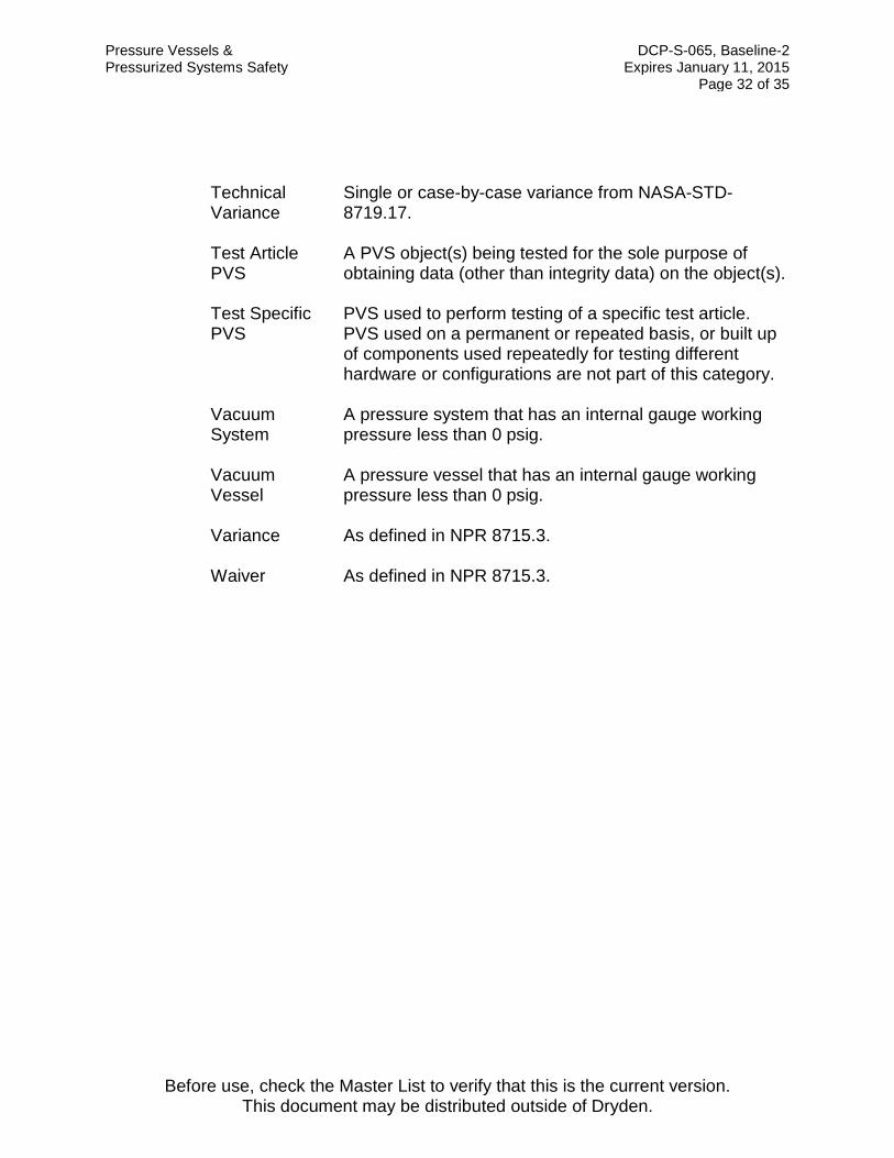
Technical Variance
Single or case-by-case variance from NASA-STD-8719.17.
Test Article PVS
A PVS object(s) being tested for the sole purpose of obtaining data (other than integrity data) on the object(s).
Test Specific PVS
PVS used to perform testing of a specific test article. PVS used on a permanent or repeated basis, or built up of components used repeatedly for testing different hardware or configurations are not part of this category.
Vacuum System
A pressure system that has an internal gauge working pressure less than 0 psig.
Vacuum Vessel
A pressure vessel that has an internal gauge working pressure less than 0 psig.
Variance As defined in NPR 8715.3.
Waiver As defined in NPR 8715.3.
Pressure Vessels & DCP-S-065, Baseline-2 Pressurized Systems Safety Expires January 11, 2015 Page 33 of 35
Before use, check the Master List to verify that this is the current version. This document may be distributed outside of Dryden.
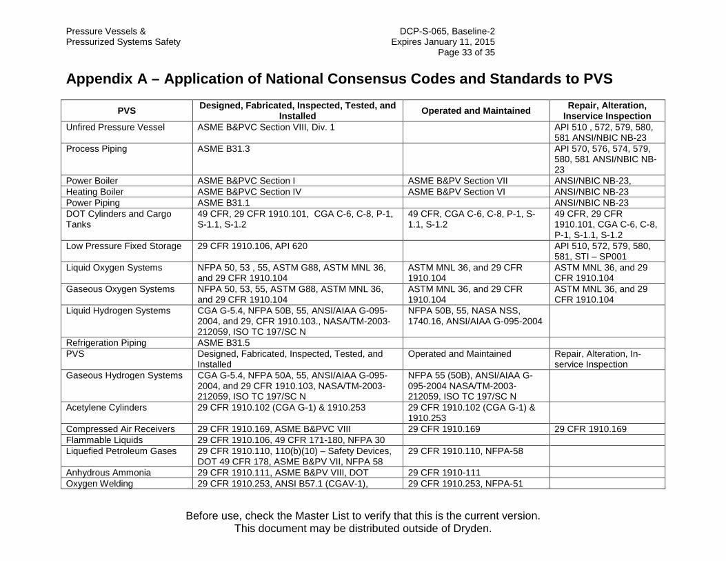
Appendix A – Application of National Consensus Codes and Standards to PVS
PVS Designed, Fabricated, Inspected, Tested, and Installed Operated and Maintained Repair, Alteration,
Inservice Inspection Unfired Pressure Vessel ASME B&PVC Section VIII, Div. 1 API 510 , 572, 579, 580,
581 ANSI/NBIC NB-23 Process Piping ASME B31.3 API 570, 576, 574, 579,
580, 581 ANSI/NBIC NB-23
Power Boiler ASME B&PVC Section I ASME B&PV Section VII ANSI/NBIC NB-23, Heating Boiler ASME B&PVC Section IV ASME B&PV Section VI ANSI/NBIC NB-23 Power Piping ASME B31.1 ANSI/NBIC NB-23 DOT Cylinders and Cargo Tanks
49 CFR, 29 CFR 1910.101, CGA C-6, C-8, P-1, S-1.1, S-1.2
49 CFR, CGA C-6, C-8, P-1, S-1.1, S-1.2
49 CFR, 29 CFR 1910.101, CGA C-6, C-8, P-1, S-1.1, S-1.2
Low Pressure Fixed Storage 29 CFR 1910.106, API 620 API 510, 572, 579, 580, 581, STI – SP001
Liquid Oxygen Systems NFPA 50, 53 , 55, ASTM G88, ASTM MNL 36, and 29 CFR 1910.104
ASTM MNL 36, and 29 CFR 1910.104
ASTM MNL 36, and 29 CFR 1910.104
Gaseous Oxygen Systems NFPA 50, 53, 55, ASTM G88, ASTM MNL 36, and 29 CFR 1910.104
ASTM MNL 36, and 29 CFR 1910.104
ASTM MNL 36, and 29 CFR 1910.104
Liquid Hydrogen Systems CGA G-5.4, NFPA 50B, 55, ANSI/AIAA G-095-2004, and 29, CFR 1910.103., NASA/TM-2003-212059, ISO TC 197/SC N
NFPA 50B, 55, NASA NSS, 1740.16, ANSI/AIAA G-095-2004
Refrigeration Piping ASME B31.5 PVS Designed, Fabricated, Inspected, Tested, and
Installed Operated and Maintained Repair, Alteration, In-
service Inspection Gaseous Hydrogen Systems CGA G-5.4, NFPA 50A, 55, ANSI/AIAA G-095-
2004, and 29 CFR 1910.103, NASA/TM-2003-212059, ISO TC 197/SC N
NFPA 55 (50B), ANSI/AIAA G-095-2004 NASA/TM-2003-212059, ISO TC 197/SC N
Acetylene Cylinders 29 CFR 1910.102 (CGA G-1) & 1910.253 29 CFR 1910.102 (CGA G-1) & 1910.253
Compressed Air Receivers 29 CFR 1910.169, ASME B&PVC VIII 29 CFR 1910.169 29 CFR 1910.169 Flammable Liquids 29 CFR 1910.106, 49 CFR 171-180, NFPA 30 Liquefied Petroleum Gases 29 CFR 1910.110, 110(b)(10) – Safety Devices,
DOT 49 CFR 178, ASME B&PV VII, NFPA 58 29 CFR 1910.110, NFPA-58
Anhydrous Ammonia 29 CFR 1910.111, ASME B&PV VIII, DOT 29 CFR 1910-111 Oxygen Welding 29 CFR 1910.253, ANSI B57.1 (CGAV-1), 29 CFR 1910.253, NFPA-51

Pressure Vessels & DCP-S-065, Baseline-2 Pressurized Systems Safety Expires January 11, 2015 Page 34 of 35
Before use, check the Master List to verify that this is the current version. This document may be distributed outside of Dryden.
NFPA-51 DOT Cylinders 49 CFR 100-180, 29 CFR 1910.101, (CGA S-1.1,
S-1.2, S-1.3) 29 CFR 1910.101, (CGA P-1, S-1.1, S-1.2)
29 CFR 1910.101, (CGA C-6, C-8) and ANSI/NB-23
Tanks (fixed) 29 CFR 1910.106 (API-12A, -12B, -12D, -12F, -620, -650, -2000), ASME B&PVC VIII, UL-58, -80, -142), AWWA D-100., UFGS 13209.N
API 510, 572, 579, 580, 581, 653
Building Services and Piping ASME B31.9 Risk Based Inspection API 580, API 581, API -
570, API -510 Pressure Gauges ASME B40.100, US-404 Pressure Relief Devices ASME PTC 25-2001 Pressure Regulator CGA E-4 Space Systems Metallic Pressure Vessels
ANSI/AIAA S-080
Space Systems Composite Overwrapped Pressure Vessels (COPV)
ANSI/AIAA S-081

Pressure Vessels & DCP-S-065, Baseline-2 Pressurized Systems Safety Expires January 11, 2015 Page 35 of 35
Before use, check the Master List to verify that this is the current version. This document may be distributed outside of Dryden.
Document History Log
IPP Review Date: 12-21-09 This page is for informational purposes and does not have to be retained with the document.
Status Change
Document Revision
Effective Date Description of Change
Baseline 01-11-10 Replaces DCP-S-009, Chapter 8. Significant rewrite of entire document.
Admin Change Baseline-1 11-17-10 Updated footer to show that the document may be
distributed outside of Dryden.
Admin change Baseline-2 07-26-11
• Updated Section 3.0. • Updated Section 17.2. • Minor editorial changes.