drylin r inch mm - igus® inc. · tum-01-30 30 .0400 -.0850 34 67 — 5.0 0.8 4.0 0.390 low...
TRANSCRIPT
Part No. Nominal di B B r t f z01/20 02/22
Standard Short
Size H7 h10 +0.05 +0.1 +0.5 +0.2
JUM-01(02)(20)(22) 10 12 29 26 3.0 0.8 1.0 2.6
JUM-01(02)(20)(22) / TUM-01-12 12 14 32 28 3.0 0.8 1.5 3.1
JUM-01(02)(20)(22) / TUM-01-16 16 18 36 30 3.5 0.8 1.7 3.6
JUM-01(02)(20)(22) / TUM-01-20 20 23 45 30 5.0 0.8 2.0 3.6
JUM-01(02)(20)(22) / TUM-01-25 25 28 58 40 5.0 0.8 2.0 4.1
JUM-01(02)(20)(22) / TUM-01-30 30 34 68 50 5.0 0.8 2.0 4.1
JUM-01(02)(20)(22) 40 44 80 60 6.0 1.3 2.5 5.1
JUM-01(02)(20)(22) 50 55 100 70 7.0 1.3 2.5 6.1
®
29.24
Dry
Lin
®R
Lin
ear
Gu
ide
Sys
tem
s
Inte
rnet
: h
ttp
://w
ww
.igu
s.co
mem
ail:
sale
s@ig
us.
com
Qu
ickS
pec
: h
ttp
://w
ww
.igu
s.co
m/i
glid
e-q
uic
ksp
ec
Tele
ph
on
e1-
800-
521-
2747
Fax
1-
401-
438-
7270
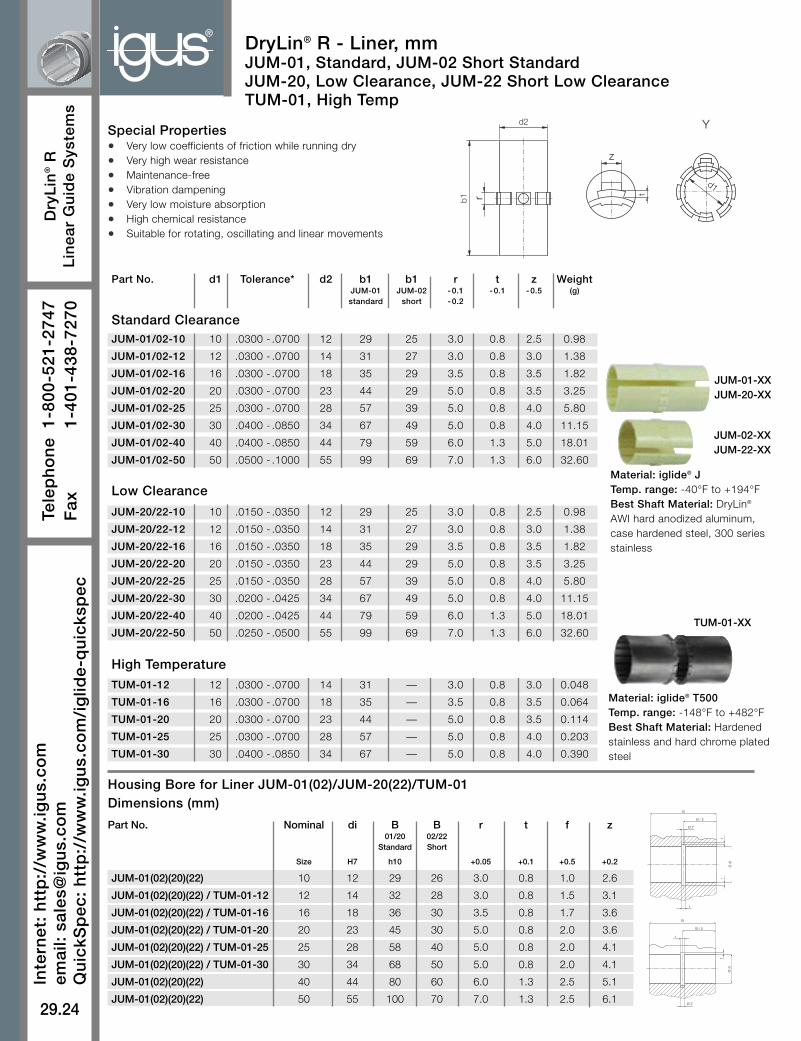
DryLin® R - Liner, mmJUM-01, Standard, JUM-02 Short StandardJUM-20, Low Clearance, JUM-22 Short Low ClearanceTUM-01, High Temp
Material: iglide® JTemp. range: -40°F to +194°FBest Shaft Material: DryLin®
AWI hard anodized aluminum,case hardened steel, 300 seriesstainless
Material: iglide® T500Temp. range: -148°F to +482°FBest Shaft Material: Hardenedstainless and hard chrome platedsteel
Special Properties• Very low coefficients of friction while running dry
• Very high wear resistance
• Maintenance-free
• Vibration dampening
• Very low moisture absorption
• High chemical resistance
• Suitable for rotating, oscillating and linear movements
rb1
d2 Y
d1
z
t
Housing Bore for Liner JUM-01(02)/JUM-20(22)/TUM-01Dimensions (mm)
Part No. d1 Tolerance* d2 b1 b1 r t z WeightJUM-01 JUM-02 -0.1 -0.1 -0.5 (g)standard short -0.2
JUM-01/02-10 10 .0300 - .0700 12 29 25 3.0 0.8 2.5 0.98
JUM-01/02-12 12 .0300 - .0700 14 31 27 3.0 0.8 3.0 1.38
JUM-01/02-16 16 .0300 - .0700 18 35 29 3.5 0.8 3.5 1.82
JUM-01/02-20 20 .0300 - .0700 23 44 29 5.0 0.8 3.5 3.25
JUM-01/02-25 25 .0300 - .0700 28 57 39 5.0 0.8 4.0 5.80
JUM-01/02-30 30 .0400 - .0850 34 67 49 5.0 0.8 4.0 11.15
JUM-01/02-40 40 .0400 - .0850 44 79 59 6.0 1.3 5.0 18.01
JUM-01/02-50 50 .0500 - .1000 55 99 69 7.0 1.3 6.0 32.60
JUM-20/22-10 10 .0150 - .0350 12 29 25 3.0 0.8 2.5 0.98
JUM-20/22-12 12 .0150 - .0350 14 31 27 3.0 0.8 3.0 1.38
JUM-20/22-16 16 .0150 - .0350 18 35 29 3.5 0.8 3.5 1.82
JUM-20/22-20 20 .0150 - .0350 23 44 29 5.0 0.8 3.5 3.25
JUM-20/22-25 25 .0150 - .0350 28 57 39 5.0 0.8 4.0 5.80
JUM-20/22-30 30 .0200 - .0425 34 67 49 5.0 0.8 4.0 11.15
JUM-20/22-40 40 .0200 - .0425 44 79 59 6.0 1.3 5.0 18.01
JUM-20/22-50 50 .0250 - .0500 55 99 69 7.0 1.3 6.0 32.60
TUM-01-12 12 .0300 - .0700 14 31 — 3.0 0.8 3.0 0.048
TUM-01-16 16 .0300 - .0700 18 35 — 3.5 0.8 3.5 0.064
TUM-01-20 20 .0300 - .0700 23 44 — 5.0 0.8 3.5 0.114
TUM-01-25 25 .0300 - .0700 28 57 — 5.0 0.8 4.0 0.203
TUM-01-30 30 .0400 - .0850 34 67 — 5.0 0.8 4.0 0.390
Low Clearance
Standard Clearance
High Temperature
JUM-01-XXJUM-20-XX
JUM-02-XXJUM-22-XX
TUM-01-XX
r
Ø Z
B / 2
B
f
Ø d
i
t
Ø d
i
r
Ø Z
B / 2
B
t

Part No. Nominal di B r t f z WSize H7 h10 +0.05 +0.1 +0.5 +0.2 +0.2
JUMO-01 / JUMO-20-10 10 12 29 3.0 0.8 1.0 2.6 7.3
JUMO-01 / JUMO-20-12 12 14 32 3.0 0.8 1.5 3.1 9.0
JUMO-01 / JUMO-20-16 16 18 36 3.5 0.8 1.7 3.6 11.6
JUMO-01 / JUMO-20-20 20 23 45 5.0 0.8 2.0 3.6 12.0
JUMO-01 / JUMO-20-25 25 28 58 5.0 0.8 2.0 4.1 14.5
JUMO-01 / JUMO-20-30 30 34 68 5.0 0.8 2.0 4.1 16.6
JUMO-01 / JUMO-20-40 40 44 80 6.0 1.3 2.5 5.1 21.0
JUMO-01 / JUMO-20-50 50 55 100 7.0 1.3 2.5 6.1 25.5
29.25
inch
mm
PD
F:
ww
w.ig
us.
com
/ig
lide-
pd
fsC
AD
: w
ww
.igu
s.co
m/i
glid
e-C
AD
Ro
HS
info
: w
ww
.igu
s.co
m/R
oH
S
Dry
Lin
®R
Lin
ear
Gu
ide
Sys
tem
s
®
➤ OJUM-01, Page 29.36➤ OJUM-03, Page 29.38➤ OJUM-06, Page 29.46
Liners of the SeriesJUMO-01 are used in:
W
f
DryLin® R - Liner, mmJUMO-01, Open, StandardJUMO-20, Open, Low Clearance
* according to igus® testing method ➤ Page 29.57
Special Properties• Open design for supported shafts
• Very low coefficients of friction while running dry
• Very high wear resistance
• Maintenance-free
• Vibration dampening
• Very low moisture absorption
• High chemical resistance
• Suitable for rotating, oscillating and linear movements
• Recommended housing bore H7
Part No. d1 Tolerance* d2 b1 W r t z Weight+0.2 -0.1 -0.2 -0.1 -0.5 (g)
JUMO-01-10 10 .0300 - .0700 12 29 7.3 3.0 0.8 2.5 0.8
JUMO-01-12 12 .0300 - .0700 14 31 9.0 3.0 0.8 3.0 1.7
JUMO-01-16 16 .0300 - .0700 18 35 11.6 3.5 0.8 3.5 2.5
JUMO-01-20 20 .0300 - .0700 23 44 12.0 5.0 0.8 3.5 4.2
JUMO-01-25 25 .0300 - .0700 28 57 14.5 5.0 0.8 4.0 5.9
JUMO-01-30 30 .0400 - .0850 34 67 16.6 5.0 0.8 4.0 12.0
JUMO-01-40 40 .0400 - .0850 44 79 21.0 6.0 1.3 5.0 20.0
JUMO-01-50 50 .0500 - .1000 55 99 25.5 7.0 1.3 6.0 36.0
JUMO-20-10 10 .0150 - .0350 12 29 7.3 3.0 0.8 2.5 0.8
JUMO-20-12 12 .0150 - .0350 14 31 9.0 3.0 0.8 3.0 1.7
JUMO-20-16 16 .0150 - .0350 18 35 11.6 3.5 0.8 3.5 2.5
JUMO-20-20 20 .0150 - .0350 23 44 12.0 5.0 0.8 3.5 4.2
JUMO-20-25 25 .0150 - .0350 28 57 14.5 5.0 0.8 4.0 5.9
JUMO-20-30 30 .0200 - .0425 34 67 16.6 5.0 0.8 4.0 12.0
JUMO-20-40 40 .0200 - .0425 44 79 21.0 6.0 1.3 5.0 20.0
JUMO-20-50 50 .0250 - .0500 55 99 25.5 7.0 1.3 6.0 36.0
* according to igus® testing method ➤ Page 29.57
Low Clearance
Standard Clearance
Ø d
i
r
Ø Z
B / 2
B
t
Installation DrawingsHousing Bore, Dimensions (mm)
rb1
d2
Y
d1
z
t
Material: iglide® JTemp. range: -40°F to +194°FBest Shaft Material: DryLin®
AWI hard anodized aluminum,case hardened steel, 300series stainless**Call for high temperatureoptions
JUMO-01/20
®
29.26
Dry
Lin
®R
Lin
ear
Gu
ide
Sys
tem
s
Inte
rnet
: h
ttp
://w
ww
.igu
s.co
mem
ail:
sale
s@ig
us.
com
Qu
ickS
pec
: h
ttp
://w
ww
.igu
s.co
m/i
glid
e-q
uic
ksp
ec
Tele
ph
on
e1-
800-
521-
2747
Fax
1-
401-
438-
7270
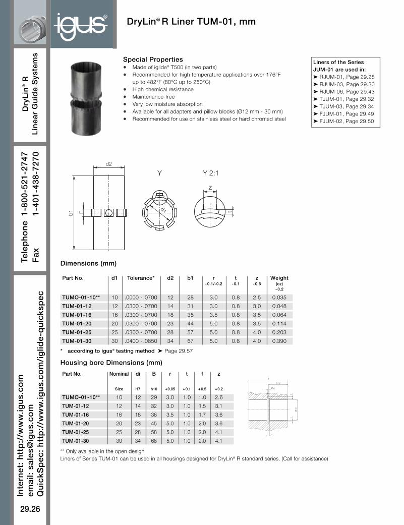
Dimensions (mm)
Housing bore Dimensions (mm)
DryLin® R Liner TUM-01, mm
** Only available in the open designLiners of Series TUM-01 can be used in all housings designed for DryLin® R standard series. (Call for assistance)
rb1
z
d2
Y Y 2:1
d1 t
Special Properties• Made of iglide® T500 (in two parts)
• Recommended for high temperature applications over 176°Fup to 482°F (80°C up to 250°C)
• High chemical resistance
• Maintenance-free
• Very low moisture absorption
• Available for all adapters and pillow blocks (Ø12 mm - 30 mm)
• Recommended for use on stainless steel or hard chromed steel
Part No. Nominal di B r t f z
Size H7 h10 +0.05 +0.1 +0.5 +0.2
TUMO-01-10** 10 12 29 3.0 1.0 1.0 2.6
TUM-01-12 12 14 32 3.0 1.0 1.5 3.1
TUM-01-16 16 18 36 3.5 1.0 1.7 3.6
TUM-01-20 20 23 45 5.0 1.0 2.0 3.6
TUM-01-25 25 28 58 5.0 1.0 2.0 4.1
TUM-01-30 30 34 68 5.0 1.0 2.0 4.1
* according to igus® testing method ➤ Page 29.57
Part No. d1 Tolerance* d2 b1 r t z Weight-0.1/-0.2 -0.1 -0.5 (oz)
-0.2
TUMO-01-10** 10 .0000 - .0700 12 28 3.0 0.8 2.5 0.035
TUM-01-12 12 .0300 - .0700 14 31 3.0 0.8 3.0 0.048
TUM-01-16 16 .0300 - .0700 18 35 3.5 0.8 3.5 0.064
TUM-01-20 20 .0300 - .0700 23 44 5.0 0.8 3.5 0.114
TUM-01-25 25 .0300 - .0700 28 57 5.0 0.8 4.0 0.203
TUM-01-30 30 .0400 - .0850 34 67 5.0 0.8 4.0 0.390
r
Ø Z
B / 2
B
f
Ø d
i
t
Liners of the SeriesJUM-01 are used in:➤ RJUM-01, Page 29.28➤ RJUM-03, Page 29.30➤ RJUM-06, Page 29.43➤ TJUM-01, Page 29.32➤ TJUM-03, Page 29.34➤ FJUM-01, Page 29.49➤ FJUM-02, Page 29.50

29.27
inch
mm
PD
F:
ww
w.ig
us.
com
/ig
lide-
pd
fsC
AD
: w
ww
.igu
s.co
m/i
glid
e-C
AD
Ro
HS
info
: w
ww
.igu
s.co
m/R
oH
S
Dry
Lin
®R
Lin
ear
Gu
ide
Sys
tem
s
®
* according to igus® testing method ➤ Page 29.57
d1
d2
dn
B
s
B1
1.5x30°
Part No. Nominal Housing Bore Tolerance for pmax. pmax. WeightSize d1 Dynamic Load Static Load (g)
Max. Min. p = 2.5 MPa p = 17.5 MPa
(N) (N)
RJM-01-08 8 16.018 16.000 .0250 - .0610 250 1750 9
RJM-01-10 10 19.021 19.000 .0320 - .0750 363 2538 14
RJM-01-12 12 22.021 22.000 .0320 - .0750 480 3360 21
RJM-01-16 16 26.021 26.000 .0320 - .0750 720 5040 28
RJM-01-20 20 32.025 32.000 .0400 - .0920 1125 7875 49
RJM-01-25 25 40.025 40.000 .0400 - .0920 1813 12688 108
RJM-01-30 30 47.025 47.000 .0400 - .0920 2550 17850 162
RJM-01-40 40 62.030 62.000 .0500 - .1120 4000 28000 334
RJM-01-50 50 75.030 75.000 .0600 - .1340 6250 43750 579
Technical Data
Part No. d1 d2 B B1 s dn
RJM-01-08 8 16 25 16.2 1.10 15.2
RJM-01-10 10 19 29 21.6 1.30 17.5
RJM-01-12 12 22 32 22.6 1.30 20.5
RJM-01-16 16 26 36 24.6 1.30 24.2
RJM-01-20 20 32 45 31.2 1.60 29.6
RJM-01-25 25 40 58 43.7 1.85 36.5
RJM-01-30 30 47 68 51.7 1.85 43.5
RJM-01-40 40 62 80 60.3 2.15 57.8
RJM-01-50 50 75 100 77.3 2.65 70.5
Special Properties
• Plain bearing made of all plastic
• Dimensions corresponds to the standard for recirculating ball bearings
• Recommended housing bore H7
• Secured by retaining clips according to DIN 471 or 472 (not included in delivery)
• Designed as a press-fit part, it will be oversized in free-state
➤ RQA-04, Page 29.53 ➤ RTA-04, Page 29.54➤ RGA-04, Page 29.55➤ RGAS-04, Page 29.56
Liners of the SeriesRJM-01 are used in:
DryLin® R Solid Plastic Bearing RJM-01, mm
Dimensions (mm)

®
29.28
Dry
Lin
®R
Lin
ear
Gu
ide
Sys
tem
s
Inte
rnet
: h
ttp
://w
ww
.igu
s.co
mem
ail:
sale
s@ig
us.
com
Qu
ickS
pec
: h
ttp
://w
ww
.igu
s.co
m/i
glid
e-q
uic
ksp
ec
Tele
ph
on
e1-
800-
521-
2747
Fax
1-
401-
438-
7270
DryLin® R Straight Linear Bearing RJUM-01, mm
Dimensions (mm)
* nominal width under 10 mm are delivered with pressfit cylindrical plain bearings* according to igus® testing method ➤ Page 29.57
Special Properties• Closed, anodized aluminum adapter
• Dimensions equivalent to the standard for recirculatingball bearings
• Equipped with JUM-01 liner made of iglide® J
• Secured by retaining clips according to DIN 471 or 472(not included in delivery)
• Recommended housing bore H7
➤ RQA-01, Page 29.53➤ RTA-01, Page 29.54➤ RGA-01, Page 29.55➤ RGAS-01, Page 29.56
RJUM-01 Bearingsare used in:
Part No. Nominal Tolerance** pmax. pmax. WeightSize Bearing Inner Dynamic Load Static Load
Diameter P = 5 MPa P = 35 MPa
(N) (N) (g)
RJZM-01-05* 5 .0250 - .0600 525 3675 5
RJZM-01-08* 8 .0320 - .0700 960 6720 9
RJUM-01-10 10 .0300 - .0880 725 5075 14
RJUM-01-12 12 .0300 - .0880 960 6720 21
RJUM-01-16 16 .0300 - .0880 1440 10080 28
RJUM-01-20 20 .0300 - .0910 2250 15750 49
RJUM-01-25 25 .0300 - .0910 3625 25375 108
RJUM-01-30 30 .0400 - .1100 5100 35700 162
RJUM-01-40 40 .0400 - .1150 8000 56000 334
RJUM-01-50 50 .0500 - .1300 12500 87500 579
Part No. d1 d2 B B1 s dnh7 h10
RJZM-01-05* 5 12 22 14.2 1.10 11.5
RJZM-01-08* 8 16 25 16.2 1.10 15.2
RJUM-01-10 10 19 29 21.6 1.30 17.5
RJUM-01-12 12 22 32 22.6 1.30 20.5
RJUM-01-16 16 26 36 24.6 1.30 24.2
RJUM-01-20 20 32 45 31.2 1.60 29.6
RJUM-01-25 25 40 58 43.7 1.85 36.5
RJUM-01-30 30 47 68 51.7 1.85 43.5
RJUM-01-40 40 62 80 60.3 2.15 57.8
RJUM-01-50 50 75 100 77.3 2.65 70.5
Load Data
Housing Bore DimensionsMETRIC
NominalSize Min. Max.
8 16.000 16.018
10 19.000 19.021
12 22.000 22.021
16 26.000 26.021
20 32.000 32.025
25 40.000 40.025
30 47.000 47.025
40 62.000 62.030
50 75.000 75.030

29.29
inch
mm
PD
F:
ww
w.ig
us.
com
/ig
lide-
pd
fsC
AD
: w
ww
.igu
s.co
m/i
glid
e-C
AD
Ro
HS
info
: w
ww
.igu
s.co
m/R
oH
S
Dry
Lin
®R
Lin
ear
Gu
ide
Sys
tem
s
®DryLin® R Straight, Low Clearance Linear Bearing RJUM-21, mm
Dimensions (mm)
Load Data
* nominal width under 10 mm are delivered with pressfit cylindrical plain bearings* according to igus® testing method ➤ Page 29.57
Special Properties• Closed, anodized aluminum adapter
• Dimensions equivalent to the standard for recirculatingball bearings
• Equipped with JUM-20 liner made of iglide® J
• Secured by retaining clips according to DIN 471 or 472(not included in delivery)
• Recommended housing bore H7
➤ RQA-01, Page 29.53➤ RTA-01, Page 29.54➤ RGA-01, Page 29.55➤ RGAS-01, Page 29.56
RJUM-21 Bearings areused in:
Part No. Nominal Tolerance** pmax. pmax. WeightSize Bearing Inner Dynamic Load Static Load (g)
Diameter P = 5 MPa P = 35 MPa
(N) (N)
RJZM-21-05* 5 .0125 - .0300 525 3675 5
RJZM-21-08* 8 .0160 - .0350 960 6720 9
RJUM-21-10 10 .0150 - .0440 725 5075 14
RJUM-21-12 12 .0150 - .0440 960 6720 21
RJUM-21-16 16 .0150 - .0440 1440 10080 28
RJUM-21-20 20 .0150 - .0440 2250 15750 49
RJUM-21-25 25 .0150 - .0440 3625 25375 108
RJUM-21-30 30 .0200 - .0550 5100 35700 162
RJUM-21-40 40 .0200 - .0575 8000 56000 334
RJUM-21-50 50 .0250 - .0650 12500 87500 579
Part No. d1 d2 B B1 s dnh7 h10
RJZM-21-05* 5 12 22 14.2 1.10 11.5
RJZM-21-08* 8 16 25 16.2 1.10 15.2
RJUM-21-10 10 19 29 21.6 1.30 17.5
RJUM-21-12 12 22 32 22.6 1.30 20.5
RJUM-21-16 16 26 36 24.6 1.30 24.2
RJUM-21-20 20 32 45 31.2 1.60 29.6
RJUM-21-25 25 40 58 43.7 1.85 36.5
RJUM-21-30 30 47 68 51.7 1.85 43.5
RJUM-21-40 40 62 80 60.3 2.15 57.8
RJUM-21-50 50 75 100 77.3 2.65 70.5

®
29.30
Dry
Lin
®R
Lin
ear
Gu
ide
Sys
tem
s
Inte
rnet
: h
ttp
://w
ww
.igu
s.co
mem
ail:
sale
s@ig
us.
com
Qu
ickS
pec
: h
ttp
://w
ww
.igu
s.co
m/i
glid
e-q
uic
ksp
ec
Tele
ph
on
e1-
800-
521-
2747
Fax
1-
401-
438-
7270
Part No. Nominal Housing Tolerance** pmax. pmax. WeightSize Bore i.d. Bearing Inner Dynamic Load Static Load (g)
h7 Diameter P =5 MPa P = 35 MPa
(mm) (N) (N)
RJZM-03-08* 8 16 .0320 - .0700 960 6720 8
RJUM-03-10 10 19 .0300 - .0880 725 5075 11
RJUM-03-12 12 22 .0300 - .0880 960 6720 17
RJUM-03-16 16 26 .0300 - .0880 1440 10080 23
RJUM-03-20 20 32 .0300 - .0910 2250 15750 44
RJUM-03-25 25 40 .0300 - .0910 3625 25375 92
RJUM-03-30 30 47 .0400 - .1100 5100 35700 145
RJUM-03-40 40 62 .0400 - .1150 8000 56000 311
RJUM-03-50 50 75 .0500 - .1300 12500 87500 542
Special Properties• Closed aluminum adapter with
- reduced outer diameter - spherical area on the outer diameter forautomatic alignment compensation - O-rings for elastic seating- hard-anodized
• Equipped with JUM-01 liner made of iglide® J
• Dimensions otherwise equivalent to the standardfor recirculating ball bearings
• Secured by retaining clips according to DIN 471 or472 (not included in delivery)
• Recommended housing bore H7• O-ring grease recommended for install
* nominal width under 10 mm are delivered with pressfit cylindrical plain bearings* according to igus® testing method ➤ Page 29.57
➤ RQA-01, Page 29.53➤ RTA-01, Page 29.54➤ RGA-01, Page 29.55➤ RGAS-01, Page 29.56
RJUM-03 Bearings areused in:
Dimensions (mm)
Load Data
Part No. d1 d2 B B1 s dn ds do o e Rh8 h10 H10 H10 h10 h10 h10 +0.1
RJZM-03-08* 8 15.8 24.9 16.4 1.10 15.0 15.5 13.2 1.86 5.0 20.0
RJUM-03-10 10 18.8 28.9 21.8 1.30 17.5 18.5 15.4 1.86 5.0 13.0
RJUM-03-12 12 21.8 31.9 22.8 1.30 20.5 21.5 18.4 1.86 6.0 18.0
RJUM-03-16 16 25.8 35.9 24.9 1.30 24.2 25.5 20.4 2.86 8.0 32.0
RJUM-03-20 20 31.8 44.8 31.5 1.60 29.6 31.5 26.4 2.86 10.0 50.0
RJUM-03-25 25 39.8 57.8 44.1 1.85 36.5 39.5 34.4 2.86 12.5 39.0
RJUM-03-30 30 46.7 67.8 52.1 1.85 43.5 46.0 41.4 2.86 15.0 57.0
RJUM-03-40 40 61.7 79.8 60.9 2.15 57.8 61.0 56.4 2.86 20.0 100.0
RJUM-03-50 50 74.7 99.8 78.0 2.65 70.5 74.0 69.4 2.86 25.0 157.0
DryLin® R Self-Aligning Linear Bearing RJUM-03, mm
Housing Bore DimensionsMETRIC
NominalSize Min. Max.
8 16.000 16.018
10 19.000 19.021
12 22.000 22.021
16 26.000 26.021
20 32.000 32.025
25 40.000 40.025
30 47.000 47.025
40 62.000 62.030
50 75.000 75.030

29.31
inch
mm
PD
F:
ww
w.ig
us.
com
/ig
lide-
pd
fsC
AD
: w
ww
.igu
s.co
m/i
glid
e-C
AD
Ro
HS
info
: w
ww
.igu
s.co
m/R
oH
S
Dry
Lin
®R
Lin
ear
Gu
ide
Sys
tem
s
®
Load Data
Part No. Nominal Housing Tolerance** pmax. pmax. WeightSize Bore Bearing Inner Dynamic Load Static Load (g)
i.d. Diameter P = 5 MPa P = 35 MPa
(mm) (N) (N)
RJZM-23-08* 8 16 .0160 - .0350 960 6720 8
RJUM-23-10 10 19 .0150 - .0440 725 5075 11
RJUM-23-12 12 22 .0150 - .0440 960 6720 17
RJUM-23-16 16 26 .0150 - .0440 1440 10080 23
RJUM-23-20 20 32 .0150 - .0455 2250 15750 44
RJUM-23-25 25 40 .0150 - .0455 3625 25375 92
RJUM-23-30 30 47 .0200 - .0550 5100 35700 145
RJUM-23-40 40 62 .0200 - .0575 8000 56000 311
RJUM-23-50 50 75 .0250 - .0650 12500 87500 542
Special Properties• Closed aluminum adapter with
- reduced outer diameter - spherical area on the outer diameter forautomatic alignment compensation - O-rings for elastic seating- hard-anodized
• Equipped with JUM-20 liner made of iglide® J
• Dimensions otherwise equivalent to the standard forrecirculating ball bearings
• Secured by retaining clips according to DIN 471 or472 (not included in delivery)
• Recommended housing bore H7• O-ring grease recommended for install
* nominal width under 10 mm are delivered with pressfit cylindrical plain bearings* according to igus® testing method ➤ Page 29.57
➤ RQA-01, Page 29.53➤ RTA-01, Page 29.54➤ RGA-01, Page 29.55➤ RGAS-01, Page 29.56
RJUM-23 Bearings areused in:
Dimensions (mm)
Part No. d1 d2 B B1 s dn ds do o e Rh8 h10 H10 H10 h10 h10 h10 +0.1
RJZM-23-08* 8 15.8 24.9 16.4 1.10 15.0 15.5 13.2 1.86 5.0 20.0
RJUM-23-10 10 18.8 28.9 21.8 1.30 17.5 18.5 15.4 1.86 5.0 13.0
RJUM-23-12 12 21.8 31.9 22.8 1.30 20.5 21.5 18.4 1.86 6.0 18.0
RJUM-23-16 16 25.8 35.9 24.9 1.30 24.2 25.5 20.4 2.86 8.0 32.0
RJUM-23-20 20 31.8 44.8 31.5 1.60 29.6 31.5 26.4 2.86 10.0 50.0
RJUM-23-25 25 39.8 57.8 44.1 1.85 36.5 39.5 34.4 2.86 12.5 39.0
RJUM-23-30 30 46.7 67.8 52.1 1.85 43.5 46.0 41.4 2.86 15.0 57.0
RJUM-23-40 40 61.7 79.8 60.9 2.15 57.8 61.0 56.4 2.86 20.0 100.0
RJUM-23-50 50 74.7 99.8 78.0 2.65 70.5 74.0 69.4 2.86 25.0 157.0
DryLin® R Self-Aligning, Low Clearance Linear Bearing RJUM-23, mm

®
29.32
Dry
Lin
®R
Lin
ear
Gu
ide
Sys
tem
s
Inte
rnet
: h
ttp
://w
ww
.igu
s.co
mem
ail:
sale
s@ig
us.
com
Qu
ickS
pec
: h
ttp
://w
ww
.igu
s.co
m/i
glid
e-q
uic
ksp
ec
Tele
ph
on
e1-
800-
521-
2747
Fax
1-
401-
438-
7270
DryLin® R Straight, Split Linear BearingTJUM-01, mm
Special Properties• Split, anodized aluminum adapter
• Dimensions equivalent to the standard forrecirculating ball bearings
• Equipped with JUM-01 liner made of iglide® J
• Secured by retaining clips according to DIN471 or 472 (not included in delivery)
• Recommended housing bore H7
Part No. d1 d2 Tolerance B B1 s dnh10 H10 H10
TJUM-01-10 10 19 - .0200 /- .0400 29 21.6 1.30 17.5
TJUM-01-12 12 22 - .0200 /- .0400 32 22.6 1.30 20.5
TJUM-01-16 16 26 - .0200 /- .0400 36 24.6 1.30 24.2
TJUM-01-20 20 32 - .0200 /- .0450 45 31.2 1.60 29.6
TJUM-01-25 25 40 - .0300 /- .0550 58 43.7 1.85 36.5
TJUM-01-30 30 47 - .0300 /- .0550 68 51.7 1.85 43.5
TJUM-01-40 40 62 - .0300 /- .0600 80 60.3 2.15 57.8
TJUM-01-50 50 75 - .0300 /- .0600 100 77.3 2.65 70.5
Dimensions (mm)
* according to igus® testing method ➤ Page 29.57
➤ RQA-01, Page 29.53➤ RTA-01, Page 29.54➤ RGA-01, Page 29.55➤ RGAS-01, Page 29.56
TJUM-01 Bearings areused in:
Part No. Nominal Tolerance* pmax. pmax. WeightSize Bearing Inner Dynamic Load Static Load (g)
Diameter P = 5 MPa P = 35 MPa
(N) (N)
TJUM-01-10 10 .0300 - .0920 725 5075 14
TJUM-01-12 12 .0300 - .0970 960 6720 19
TJUM-01-16 16 .0300 - .0970 1440 10080 27
TJUM-01-20 20 .0300 - .1030 2250 15750 49
TJUM-01-25 25 .0300 - .1030 3625 25375 106
TJUM-01-30 30 .0400 - .1240 5100 35700 166
TJUM-01-40 40 .0400 - .1240 8000 56000 347
TJUM-01-50 50 .0500 - .1460 12500 87500 577
Housing Bore DimensionsMETRIC
NominalSize Min. Max.
8 16.000 16.018
10 19.000 19.021
12 22.000 22.021
16 26.000 26.021
20 32.000 32.025
25 40.000 40.025
30 47.000 47.025
40 62.000 62.030
50 75.000 75.030
Load Data

29.33
inch
mm
PD
F:
ww
w.ig
us.
com
/ig
lide-
pd
fsC
AD
: w
ww
.igu
s.co
m/i
glid
e-C
AD
Ro
HS
info
: w
ww
.igu
s.co
m/R
oH
S
Dry
Lin
®R
Lin
ear
Gu
ide
Sys
tem
s
®DryLin® R Straight, Split, Low Clearance Linear BearingTJUM-21, mm
Special Properties• Split, anodized aluminum adapter
• Dimensions equivalent to the standard forrecirculating ball bearings
• Equipped with JUM-20 liner made of iglide® J
• Secured by retaining clips according to DIN471 or 472 (not included in delivery)
• Recommended housing bore H7
Part No. d1 d2 Tolerance B B1 s dnh10 H10 H10
TJUM-21-10 10 19 - .0200 /- .0400 29 21.6 1.30 17.5
TJUM-21-12 12 22 - .0200 /- .0400 32 22.6 1.30 20.5
TJUM-21-16 16 26 - .0200 /- .0400 36 24.6 1.30 24.2
TJUM-21-20 20 32 - .0200 /- .0450 45 31.2 1.60 29.6
TJUM-21-25 25 40 - .0300 /- .0550 58 43.7 1.85 36.5
TJUM-21-30 30 47 - .0300 /- .0550 68 51.7 1.85 43.5
TJUM-21-40 40 62 - .0300 /- .0600 80 60.3 2.15 57.8
TJUM-21-50 50 75 - .0300 /- .0600 100 77.3 2.65 70.5
Dimensions (mm)
* according to igus® testing method ➤ Page 29.57
➤ RQA-01, Page 29.53➤ RTA-01, Page 29.54➤ RGA-01, Page 29.55➤ RGAS-01, Page 29.56
TJUM-21 Bearings areused in:
Part No. Nominal Tolerance* pmax. pmax. WeightSize Bearing Inner Dynamic Load Static Load (g)
Diameter P = 5 MPa P = 35 MPa
(N) (N)
TJUM-21-10 10 .0150 - .0460 725 5075 14
TJUM-21-12 12 .0150 - .0485 960 6720 19
TJUM-21-16 16 .0150 - .0485 1440 10080 27
TJUM-21-20 20 .0150 - .0515 2250 15750 49
TJUM-21-25 25 .0150 - .0515 3625 25375 106
TJUM-21-30 30 .0200 - .0620 5100 35700 166
TJUM-21-40 40 .0200 - .0620 8000 56000 347
TJUM-21-50 50 .0250 - .0730 12500 87500 577
Load Data

®
29.34
Dry
Lin
®R
Lin
ear
Gu
ide
Sys
tem
s
Inte
rnet
: h
ttp
://w
ww
.igu
s.co
mem
ail:
sale
s@ig
us.
com
Qu
ickS
pec
: h
ttp
://w
ww
.igu
s.co
m/i
glid
e-q
uic
ksp
ec
Tele
ph
on
e1-
800-
521-
2747
Fax
1-
401-
438-
7270
DryLin® R Self-Aligning, Split Linear Bearing TJUM-03, mm
Part No. Nominal Tolerance* pmax. pmax. WeightSize Bearing Dynamic Load Static Load (g)
Inner Diameter P = 5 MPa P = 35 MPa
(N) (N)
TJUM-03-10 10 .0300 - .0920 725 5075 11
TJUM-03-12 12 .0300 - .0970 960 6720 17
TJUM-03-16 16 .0300 - .0970 1440 10080 23
TJUM-03-20 20 .0300 - .1030 2250 15750 44
TJUM-03-25 25 .0300 - .1030 3625 25375 92
TJUM-03-30 30 .0400 - .1240 5100 35700 145
TJUM-03-40 40 .0400 - .1240 8000 56000 311
TJUM-03-50 50 .0500 - .1460 12500 87500 542
Part No. d1 d2 B B1 s dn ds do o e Rh10 H10 H10 h10 h10 +0.2 0.4
TJUM-03-10 10 19 -0.020 -0.040 28.9 21.8 1.30 17.5 18.5 15.4 1.86 5.0 13.0
TJUM-03-12 12 22 -0.020 -0.040 31.9 22.8 1.30 20.5 21.5 18.4 1.86 6.0 18.0
TJUM-03-16 16 26 -0.020 -0.040 35.9 24.9 1.30 24.2 25.5 20.4 2.86 8.0 32.0
TJUM-03-20 20 32 -0.020 -0.045 44.8 31.5 1.60 29.6 31.5 26.4 2.86 10.0 50.0
TJUM-03-25 25 40 -0.030 -0.055 57.8 44.1 1.85 36.5 39.5 34.4 2.86 12.5 39.0
TJUM-03-30 30 47 -0.030 -0.055 67.8 52.1 1.85 43.5 46.0 41.4 2.86 15.0 57.0
TJUM-03-40 40 62 -0.030 -0.060 79.8 60.9 2.15 57.8 61.0 56.4 2.86 20.0 100.0
TJUM-03-50 50 75 -0.030 -0.060 99.8 78.0 2.65 70.5 74.0 69.4 2.86 25.0 157.0
Dimensions (mm)
Special Properties• Split aluminum adapter with
- spherical area on the outer diameterfor self-alignment purposes
- O-rings for elastic seating
• Dimensions otherwise equivalent to the standard forrecirculating ball bearings
• Equipped with JUM-01 liner made of iglide® J
• Secured by retaining clips according to DIN 471 or 472 (notincluded in delivery)
• Recommended housing bore H7• O-ring grease recommended for install
* according to igus® testing method ➤ Page 29.57
➤ RQA-01, Page 29.53➤ RTA-01, Page 29.54➤ RGA-01, Page 29.55➤ RGAS-01, Page 29.56
TJUM-03 Bearings areused in:
Housing Bore DimensionsMETRIC
NominalSize Min. Max.
8 16.000 16.018
10 19.000 19.021
12 22.000 22.021
16 26.000 26.021
20 32.000 32.025
25 40.000 40.025
30 47.000 47.025
40 62.000 62.030
50 75.000 75.030
Load Data

29.35
inch
mm
PD
F:
ww
w.ig
us.
com
/ig
lide-
pd
fsC
AD
: w
ww
.igu
s.co
m/i
glid
e-C
AD
Ro
HS
info
: w
ww
.igu
s.co
m/R
oH
S
Dry
Lin
®R
Lin
ear
Gu
ide
Sys
tem
s
®
DryLin® R Self-Aligning, Split, Low ClearanceLinear Bearing - TJUM-23, mm
Part No. Nominal Tolerance* pmax. pmax. WeightSize Bearing Dynamic Load Static Load (g)
Inner Diameter P = 5 MPa P = 35 MPa
(N) (N)
TJUM-23-10 10 .0150 - .0460 725 5075 11
TJUM-23-12 12 .0150 - .0485 960 6720 17
TJUM-23-16 16 .0150 - .0485 1440 10080 23
TJUM-23-20 20 .0150 - .0515 2250 15750 44
TJUM-23-25 25 .0150 - .0515 3625 25375 92
TJUM-23-30 30 .0200 - .0620 5100 35700 145
TJUM-23-40 40 .0200 - .0620 8000 56000 311
TJUM-23-50 50 .0250 - .0730 12500 87500 542
Part No. d1 d2 B B1 s dn ds do o e Rh10 H10 H10 h10 h10 +0.2 0.4
TJUM-23-10 10 19 -0.020 -0.040 28.9 21.8 1.30 17.5 18.5 15.4 1.86 5.0 13.0
TJUM-23-12 12 22 -0.020 -0.040 31.9 22.8 1.30 20.5 21.5 18.4 1.86 6.0 18.0
TJUM-23-16 16 26 -0.020 -0.040 35.9 24.9 1.30 24.2 25.5 20.4 2.86 8.0 32.0
TJUM-23-20 20 32 -0.020 -0.045 44.8 31.5 1.60 29.6 31.5 26.4 2.86 10.0 50.0
TJUM-23-25 25 40 -0.030 -0.055 57.8 44.1 1.85 36.5 39.5 34.4 2.86 12.5 39.0
TJUM-23-30 30 47 -0.030 -0.055 67.8 52.1 1.85 43.5 46.0 41.4 2.86 15.0 57.0
TJUM-23-40 40 62 -0.030 -0.060 79.8 60.9 2.15 57.8 61.0 56.4 2.86 20.0 100.0
TJUM-23-50 50 75 -0.030 -0.060 99.8 78.0 2.65 70.5 74.0 69.4 2.86 25.0 157.0
Dimensions (mm)
Special Properties• Split aluminum adapter with
- spherical area on the outer diameterfor self-alignment purposes
- O-rings for elastic seating
• Dimensions otherwise equivalent to the standard forrecirculating ball bearings
• Equipped with JUM-20 liner made of iglide® J
• Secured by retaining clips according to DIN 471 or 472(not included in delivery)
• Recommended housing bore H7• O-ring grease recommended for install
* according to igus® testing method ➤ Page 29.57
➤ RQA-01, Page 29.53➤ RTA-01, Page 29.54➤ RGA-01, Page 29.55➤ RGAS-01, Page 29.56
TJUM-23 Bearings areused in:
Load Data

®
29.36
Dry
Lin
®R
Lin
ear
Gu
ide
Sys
tem
s
Inte
rnet
: h
ttp
://w
ww
.igu
s.co
mem
ail:
sale
s@ig
us.
com
Qu
ickS
pec
: h
ttp
://w
ww
.igu
s.co
m/i
glid
e-q
uic
ksp
ec
Tele
ph
on
e1-
800-
521-
2747
Fax
1-
401-
438-
7270
DryLin® R Straight, Open Linear Bearing -OJUM-01, mm
Part No. Nominal Tolerance* pmax. pmax. WeightSize Bearing Dynamic Load Static Load (g)
Inner Diameter P = 5 MPa P = 35 MPa
(N) (N)
0º 90º 180º 0º 90º 180º
OJUM-01-10 10 .0300 - .0880 725 500 196 5075 3500 1370 11
OJUM-01-12 12 .0300 - .0880 960 635 240 6720 4445 1680 15
OJUM-01-16 16 .0300 - .0880 1440 990 396 10080 6943 2772 21
OJUM-01-20 20 .0300 - .0910 2250 1800 900 15750 12600 6300 42
OJUM-01-25 25 .0300 - .0910 3625 2953 1523 25375 20670 10658 70
OJUM-01-30 30 .0400 - .1100 5100 4250 2278 35700 29735 15946 132
OJUM-01-40 40 .0400 - .1150 8000 6810 3800 56000 47660 26660 278
OJUM-01-50 50 .0500 - .1300 12500 10750 6125 87500 75265 42875 479
Dimensions (mm)
* according to igus® testing method ➤ Page 29.57
Part No. d1 d2 B W a dn B1 s f hh7 h10 +0.1 h10 H10 H10 ±0.2 -0.5
OJUM-01-10 10 19 29 7.3 0.0 17.5 21.6 1.30 0 1.2
OJUM-01-12 12 22 32 9.0 3.0 20.5 22.6 1.30 1.33 (7°) 1.2
OJUM-01-16 16 26 36 11.6 2.2 24.2 24.6 1.30 0 1.2
OJUM-01-20 20 32 45 12.0 2.2 29.6 31.2 1.60 0 1.2
OJUM-01-25 25 40 58 14.5 3.0 36.5 43.7 1.85 -1.5 (-4.3°) 1.5
OJUM-01-30 30 47 68 16.6 3.0 43.5 51.7 1.85 2 (4.9°) 2.0
OJUM-01-40 40 62 80 21.0 3.0 57.8 60.3 2.15 1.5 (2.8°) 2.0
OJUM-01-50 50 75 100 25.5 5.0 70.5 77.3 2.65 2.5 (3.8°) 2.0
Special Properties• Open, anodized aluminum adapter for supported shafts
• Dimensions equivalent to the standard for recirculatingball bearings
• Equipped with JUMO liner made of iglide® J
• Recommended housing bore H7
• Secure the bearing with set screws(not included in the delivery)
➤ OQA-01, Page 29.53 ➤ OTA-01, Page 29.54➤ OGA-01, Page 29.55➤ OGAS-01, Page 29.56
OJUM-01 Bearings areused in:
B1B
s
W90°
fa
h
d2 dn d1
Housing Bore DimensionsMETRIC
NominalSize Min. Max.
8 16.000 16.018
10 19.000 19.021
12 22.000 22.021
16 26.000 26.021
20 32.000 32.025
25 40.000 40.025
30 47.000 47.025
40 62.000 62.030
50 75.000 75.030
Load Data
0° 90° 180°

29.37
inch
mm
PD
F:
ww
w.ig
us.
com
/ig
lide-
pd
fsC
AD
: w
ww
.igu
s.co
m/i
glid
e-C
AD
Ro
HS
info
: w
ww
.igu
s.co
m/R
oH
S
Dry
Lin
®R
Lin
ear
Gu
ide
Sys
tem
s
®DryLin® R Straight, Open, Low Clearance Linear Bearing -OJUM-21, mm
Part No. Nominal Tolerance* pmax. pmax. WeightSize Bearing Dynamic Load Static Load (g)
Inner Diameter P = 5 MPa P = 35 MPa
(N) (N)
0º 90º 180º 0º 90º 180º
OJUM-21-10 10 .0150 - .0440 725 500 196 5075 3500 1370 11
OJUM-21-12 12 .0150 - .0440 960 635 240 6720 4445 1680 15
OJUM-21-16 16 .0150 - .0440 1440 990 396 10080 6943 2772 21
OJUM-21-20 20 .0150 - .0455 2250 1800 900 15750 12600 6300 42
OJUM-21-25 25 .0150 - .0455 3625 2953 1523 25375 20670 10658 70
OJUM-21-30 30 .0200 - .0550 5100 4250 2278 35700 29735 15946 132
OJUM-21-40 40 .0200 - .0575 8000 6810 3800 56000 47660 26660 278
OJUM-21-50 50 .0250 - .0650 12500 10750 6125 87500 75265 42875 479
Dimensions (mm)
* according to igus® testing method ➤ Page 29.57
Part No. d1 d2 B W a dn B1 s f hh7 h10 +0.1 h10 H10 H10 ±0.2 -0.5
OJUM-21-10 10 19 29 7.3 0.0 17.5 21.6 1.30 0 1.2
OJUM-21-12 12 22 32 9.0 3.0 20.5 22.6 1.30 1.33 (7°) 1.2
OJUM-21-16 16 26 36 11.6 2.2 24.2 24.6 1.30 0 1.2
OJUM-21-20 20 32 45 12.0 2.2 29.6 31.2 1.60 0 1.2
OJUM-21-25 25 40 58 14.5 3.0 36.5 43.7 1.85 -1.5 (-4.3°) 1.5
OJUM-21-30 30 47 68 16.6 3.0 43.5 51.7 1.85 2 (4.9°) 2.0
OJUM-21-40 40 62 80 21.0 3.0 57.8 60.3 2.15 1.5 (2.8°) 2.0
OJUM-21-50 50 75 100 25.5 5.0 70.5 77.3 2.65 2.5 (3.8°) 2.0
Special Properties• Open, anodized aluminum adapter for supported shafts
• Dimensions equivalent to the standard for recirculatingball bearings
• Equipped with JUMO-20 liner made of iglide® J
• Recommended housing bore H7
• Secured the bearing with set screws(not included in the delivery)
➤ OQA-01, Page 29.53 ➤ OTA-01, Page 29.54➤ OGA-01, Page 29.55➤ OGAS-01, Page 29.56
OJUM-21 Bearings areused in:
B1B
s
W90°
fa
h
d2 dn d1
Load Data
0° 90° 180°

®
29.38
Dry
Lin
®R
Lin
ear
Gu
ide
Sys
tem
s
Inte
rnet
: h
ttp
://w
ww
.igu
s.co
mem
ail:
sale
s@ig
us.
com
Qu
ickS
pec
: h
ttp
://w
ww
.igu
s.co
m/i
glid
e-q
uic
ksp
ec
Tele
ph
on
e1-
800-
521-
2747
Fax
1-
401-
438-
7270
Dimensions (mm)
* according to igus® testing method ➤ Page 29.57
Special Properties• Open, aluminum adapter with
- reduced outer diameter - spherical area on the outer diameter for automatic align-ment compensation- O-rings for elastic seating- hard-anodized
• Dimensions correspond to the standard forrecirculating ball bearings
• Equipped with JUMO liner made of iglide® J
• Recommended housing bore H7
• Attachment by mounting bolts (not included in delivery)
➤ OQA-01, Page 29.53 ➤ OTA-01, Page 29.54➤ OGA-01, Page 29.55➤ OGAS-01, Page 29.56
OJUM-03 Bearings areused in:
Part No. Nominal Housing Tolerance* pmax. pmax. WeightSize bore Bearing Dynamic Load Static Load (g)
Inner Diameter P = 5 MPa P = 35 MPa
(N) (N)
0º 90º 180º 0º 90º 180º
OJUM-03-10 10 19 .0300 - .0880 725 500 196 5075 3500 1370 10
OJUM-03-12 12 22 .0300 - .0880 960 635 240 6720 4445 1680 13
OJUM-03-16 16 26 .0300 - .0880 1440 990 396 10080 6943 2772 19
OJUM-03-20 20 32 .0300 - .0910 2250 1800 900 15750 12600 6300 38
OJUM-03-25 25 40 .0300 - .0910 3625 2953 1523 25375 20670 10658 63
OJUM-03-30 30 47 .0400 - .1100 5100 4250 2278 35700 29735 15946 119
OJUM-03-40 40 62 .0400 - .1150 8000 6810 3800 56000 47660 26660 250
OJUM-03-50 50 75 .0500 - .1300 12500 10750 6125 87500 75265 42875 431
Part No. d2 ds e o do B1 s B R W a f h ah7 h10 +0.1 h10 H10 H10 h10 +0.1 ±0.2 -0.5
OJUM-03-10 18.8 18.5 5.0 1.86 15.4 21.8 1.30 28.9 13.0 7.3 0.0 0 1.2 10
OJUM-03-12 21.8 21.5 6.0 1.86 18.4 22.8 1.30 31.9 18.0 9.0 3.0 1.33 (7°) 1.2 12
OJUM-03-16 25.8 25.5 8.0 2.86 20.4 24.9 1.30 35.9 32.0 11.6 2.2 0 1.2 16
OJUM-03-20 31.8 31.5 10.0 2.86 26.4 31.5 1.60 44.8 50.0 12.0 2.2 0 1.2 20
OJUM-03-25 39.8 39.0 12.5 2.86 34.4 44.1 1.85 57.8 39.0 14.5 3.0 -1.5 (-4.3°) 1.5 25
OJUM-03-30 46.7 46.0 15.0 2.86 41.4 52.1 1.85 67.8 57.0 16.6 3.0 2 (4.9°) 2 30
OJUM-03-40 61.7 61.0 20.0 2.86 56.4 60.9 2.15 79.8 100.0 21.0 3.0 1.5 (2.8°) 2 40
OJUM-03-50 74.7 74.0 25.0 2.86 69.4 78.0 2.65 99.8 157.0 25.5 5.0 2.5 (3.8°) 2 50
DryLin® R Self Aligning, Open Linear Bearing -OJUM-03, mm
W
fa
h
e
B1B
sR
d1dods 90°
d2
Housing Bore DimensionsMETRIC
NominalSize Min. Max.
8 16.000 16.018
10 19.000 19.021
12 22.000 22.021
16 26.000 26.021
20 32.000 32.025
25 40.000 40.025
30 47.000 47.025
40 62.000 62.030
50 75.000 75.030
Load Data
0° 90° 180°

29.39
inch
mm
PD
F:
ww
w.ig
us.
com
/ig
lide-
pd
fsC
AD
: w
ww
.igu
s.co
m/i
glid
e-C
AD
Ro
HS
info
: w
ww
.igu
s.co
m/R
oH
S
Dry
Lin
®R
Lin
ear
Gu
ide
Sys
tem
s
®
Dimensions (mm)
Special Properties• Open, aluminum adapter with
- reduced outer diameter - spherical area on the outer diameter for automatic alignmentcompensation- O-rings for elastic seating- hard-anodized
• Dimensions correspond to the standard for recirculating ballbearings
• Equipped with JUMO-20 liner made of iglide® J
• Recommended housing bore H7• O-ring grease recommended for install
• Attachment by mounting bolts (not included in delivery)
➤ OQA-01, Page 29.55 ➤ OTA-01, Page 29.56➤ OGA-01, Page 29.57➤ OGAS-01, Page 29.58
OJUM-23 Bearings areused in:
Part No. Nominal Housing Tolerance* pmax. pmax. WeightSize bore Bearing Dynamic Load Static Load (g)
Inner Diameter P = 5 MPa P = 35 MPa
(N) (N)
0º 90º 180º 0º 90º 180º
OJUM-23-10 10 19 .0150 - .0440 725 500 196 5075 3500 1370 10
OJUM-23-12 12 22 .0150 - .0440 960 635 240 6720 4445 1680 13
OJUM-23-16 16 26 .0150 - .0440 1440 990 396 10080 6943 2772 19
OJUM-23-20 20 32 .0150 - .0455 2250 1800 900 15750 12600 6300 38
OJUM-23-25 25 40 .0150 - .0455 3625 2953 1523 25375 20670 10658 63
OJUM-23-30 30 47 .0200 - .0550 5100 4250 2278 35700 29735 15946 119
OJUM-23-40 40 62 .0200 - .0575 8000 6810 3800 56000 47660 26660 250
OJUM-23-50 50 75 .0250 - .0650 12500 10750 6125 87500 75265 42875 431
Part No. d2 ds e o do B1 s B R W a f h ah7 h10 +0.1 h10 H10 H10 h10 +0.1 ±0.2 -0.5
OJUM-23-10 18.8 18.5 5.0 1.86 15.4 21.8 1.30 28.9 13.0 7.3 0.0 0 1.2 10
OJUM-23-12 21.8 21.5 6.0 1.86 18.4 22.8 1.30 31.9 18.0 9.0 3.0 1.33 (7°) 1.2 12
OJUM-23-16 25.8 25.5 8.0 2.86 20.4 24.9 1.30 35.9 32.0 11.6 2.2 0 1.2 16
OJUM-23-20 31.8 31.5 10.0 2.86 26.4 31.5 1.60 44.8 50.0 12.0 2.2 0 1.2 20
OJUM-23-25 39.8 39.0 12.5 2.86 34.4 44.1 1.85 57.8 39.0 14.5 3.0 -1.5 (-4.3°) 1.5 25
OJUM-23-30 46.7 46.0 15.0 2.86 41.4 52.1 1.85 67.8 57.0 16.6 3.0 2 (4.9°) 2 30
OJUM-23-40 61.7 61.0 20.0 2.86 56.4 60.9 2.15 79.8 100.0 21.0 3.0 1.5 (2.8°) 2 40
OJUM-23-50 74.7 74.0 25.0 2.86 69.4 78.0 2.65 99.8 157.0 25.5 5.0 2.5 (3.8°) 2 50
DryLin® R Self Aligning, Open, Low Clearance Linear Bearing - OJUM-23, mm
* according to igus® testing method ➤ Page 29.57
W
fa
h
e
B1B
sR
d1dods 90°
d2
Load Data
0° 90° 180°

®
29.40
Dry
Lin
®R
Lin
ear
Gu
ide
Sys
tem
s
Inte
rnet
: h
ttp
://w
ww
.igu
s.co
mem
ail:
sale
s@ig
us.
com
Qu
ickS
pec
: h
ttp
://w
ww
.igu
s.co
m/i
glid
e-q
uic
ksp
ec
Tele
ph
on
e1-
800-
521-
2747
Fax
1-
401-
438-
7270
DryLin® R Thin Walled, Linear Bearing RJUM-02, mm
Part No. Nominal Housing Tolerance** pmax. pmax. Weight d1 d2 BSize Bore i.d. Bearing i.d. Dynamic Load Static Load (g) k7 h10
h7 Min. Max. P = 5 MPa P = 35 MPa
(N) (N)
RJZM-02-08* 8 15 .0320 - .0700 650 4550 6 8 15 24
RJUM-02-10 10 17 .0300 - .0880 650 4550 8 10 17 26
RJUM-02-12 12 19 .0300 - .0880 840 5880 10 12 19 28
RJUM-02-16 16 24 .0300 - .0880 1200 8400 17 16 24 30
RJUM-02-20 20 28 .0300 - .0910 1500 10500 18 20 28 30
RJUM-02-25 25 35 .0300 - .0910 2500 17500 42 25 35 40
RJUM-02-30 30 40 .0400 - .1100 3750 26250 56 30 40 50
RJUM-02-40 40 52 .0400 - .1150 6000 42000 113 40 52 60
RJUM-02-50 50 60 .0500 - .1300 8750 61250 147 50 60 70
Dimensions (mm)
Special Properties• Closed, anodized aluminum adapter
• Dimensions equivalent to the standard for recirculating ball bearings
• Equipped with JUM-02 liner made of iglide® J
• Secured by pressfit in a recommended housing bore
• Recommended housing bore H7 for steel housings or K7 for aluminum
Part No. Nominal Housing Tolerance** pmax. pmax. Weight d1 d2 BSize Bore Bearing i.d. Dynamic Load Static Load (g) k7 h10
i.d. Min. Max. P = 5 MPa P = 35 MPa
(N) (N)
RJZM-02-08* 8 15 .0160 - .0350 215 1510 6 8 15 24
RJUM-22-10 10 17 .0150 - .0440 146 1022 8 10 17 26
RJUM-22-12 12 19 .0150 - .0440 188 1321 10 12 19 28
RJUM-22-16 16 24 .0150 - .0440 269 1888 17 16 24 30
RJUM-22-20 20 28 .0150 - .0455 337 2360 18 20 28 30
RJUM-22-25 25 35 .0150 - .0455 562 3934 42 25 35 40
RJUM-22-30 30 40 .0200 - .0550 843 5901 56 30 40 50
RJUM-22-40 40 52 .0200 - .0575 1348 9441 113 40 52 60
RJUM-22-50 50 60 .0250 - .0650 1967 13769 147 50 60 70
Dimensions (mm)
RJUM-02, Standard Clearance
RJUM-22, Low Clearance

29.41
inch
mm
PD
F:
ww
w.ig
us.
com
/ig
lide-
pd
fsC
AD
: w
ww
.igu
s.co
m/i
glid
e-C
AD
Ro
HS
info
: w
ww
.igu
s.co
m/R
oH
S
Dry
Lin
®R
Lin
ear
Gu
ide
Sys
tem
s
®DryLin® R Closed Pillow Block,Short Design Linear Bearing RJUM-05, mm
* according to igus® testing method ➤ Page 29.57
Special Properties• Closed, anodized aluminum housing, short design
• Contains JUM-02-XX liner
Part No. Nominal Tolerance* pmax. pmax. WeightSize Bearing Dynamic Load Static Load (g)
Inner Diameter P = 5 MPa P = 35 MPa
(N) (N)
RJUM- -10 10 .0300 - .0880 650 4550 71
RJUM- -12 12 .0300 - .0880 840 5880 78
RJUM- -16 16 .0300 - .0880 1200 8400 106
RJUM- -20 20 .0300 - .0910 1500 10500 132
RJUM- -25 25 .0300 - .0910 2500 17500 253
RJUM- -30 30 .0400 - .1100 3750 26250 374
RJUM- -40 40 .0400 - .1150 6000 42000 713
RJUM- -50 50 .0500 - .1300 8750 61250 1.168
Part No. d1 H H1 A M E S S1 S2 N1 N2 L+0.01 ±0.15-0.014
RJUM- -10 10 16 33 40 20.0 29 8.0 M 5 4.3 16 11 26
RJUM- -12 12 17 33 40 20.0 29 8.0 M 5 4.3 16 11 28
RJUM- -16 16 19 38 45 22.5 34 8.0 M 5 4.3 18 11 30
RJUM- -20 20 23 45 53 26.5 40 9.5 M 6 5.3 22 13 30
RJUM- -25 25 27 54 62 31.0 48 11.0 M 8 6.6 26 18 40
RJUM- -30 30 30 60 67 33.5 53 11.0 M 8 6.6 29 18 50
RJUM- -40 40 39 76 87 43.5 69 15.0 M10 8.4 38 22 60
RJUM- -50 50 47 92 103 51.5 82 18.0 M12 10.5 46 26 70
Dimensions (mm)
M
S
L
HH
1d1
N1
N2
S1S2
EA
Supplement the part number with one of the following choices.Example: RJUM- -10 for a standard version
For Standard version use (See page 27.24)
For Low Clearance version use (See page 27.24)
05
05
35
Load Data
XX
XX
XX
XX
XX
XX
XX
XX

®
29.42
Dry
Lin
®R
Lin
ear
Gu
ide
Sys
tem
s
Inte
rnet
: h
ttp
://w
ww
.igu
s.co
mem
ail:
sale
s@ig
us.
com
Qu
ickS
pec
: h
ttp
://w
ww
.igu
s.co
m/i
glid
e-q
uic
ksp
ec
Tele
ph
on
e1-
800-
521-
2747
Fax
1-
401-
438-
7270
DryLin® R Adjustable Pillow Block,Short Design Linear Bearing RJUME-05, mm
Special Properties• Adjustable, anodized aluminum housing, short design
• Contains JUM-02-XX liner
• With adjustable clearance for shaft dimensions 12 to 40 mm
Part No. Nominal Tolerance pmax. pmax. WeightSize Bearing Dynamic Load Static Load (g)
Inner Diameter P = 5 MPa P = 35 MPa
(N) (N)
RJUME- -12 12 adjustable 840 5880 78
RJUME- -16 16 adjustable 1200 8400 106
RJUME- -20 20 adjustable 1500 10500 132
RJUME- -25 25 adjustable 2500 17500 253
RJUME- -30 30 adjustable 3750 26250 374
RJUME- -40 40 adjustable 6000 42000 713
Dimensions (mm)
Part No. d1 H H1 A M E E1 S S1 S2 Sb N1 N2 L+0.01 ±0.15 ±0.15-0.014
RJUME- -12 12 17 33 40 20.0 29 18.0 8.0 4.3 M 5 2 16 11 28
RJUME- -16 16 19 38 45 22.5 34 19.0 8.0 4.3 M 5 2 18 11 30
RJUME- -20 20 23 45 53 26.5 40 20.0 9.5 5.3 M 6 2 22 13 30
RJUME- -25 25 27 54 62 31.0 48 25.5 11.0 6.6 M 8 2 26 18 40
RJUME- -30 30 30 60 67 33.5 53 30.5 11.0 6.6 M 8 2 29 18 50
RJUME- -40 40 39 76 87 43.5 69 36.0 15.0 8.4 M10 2 38 22 60
d1
MS1S2
N2 N1
Sb
S
LEA
E1
HH
1
Load Data
Supplement the part number with one of the following choices.Example: RJUME- -12 for a standard version
For Standard version use (See page 27.24)
For Low Clearance version use (See page 27.24)
05
05
35
XX
XX
XX
XX
XX
XX

29.43
inch
mm
PD
F:
ww
w.ig
us.
com
/ig
lide-
pd
fsC
AD
: w
ww
.igu
s.co
m/i
glid
e-C
AD
Ro
HS
info
: w
ww
.igu
s.co
m/R
oH
S
Dry
Lin
®R
Lin
ear
Gu
ide
Sys
tem
s
®DryLin® R Closed Pillow Block,Long Design Linear Bearing RJUM-06, mm
Special Properties• Closed, anodized aluminum housing, long design
• Contains JUM-01-XX liner
Dimensions (mm)
* according to igus® testing method ➤ Page 29.57
Part No. Nominal Tolerance* pmax. pmax. WeightSize Bearing Dynamic Load Static Load (kg)
Inner Diameter P = 5 MPa P = 35 MPa
(N) (N)
RJUM- -12 12 .0300 - .0880 960 6720 0.121
RJUM- -16 16 .0300 - .0880 1440 10080 0.211
RJUM- -20 20 .0300 - .0910 2250 15750 0.323
RJUM- -25 25 .0300 - .0910 3625 25375 0.651
RJUM- -30 30 .0400 - .1100 5100 35700 1.050
RJUM- -40 40 .0400 - .1150 8000 56000 1.820
RJUM- -50 50 .0500 - .1300 12500 87500 3.250
Part No. d1 H H1 A M E1 E2 S S1 S2 N1 N2 L+0.01 ±0.15 ±0.15
-0.014
RJUM- -12 12 18 35 43 21.5 32 23 8.0 M 5 4.3 16.5 11 39
RJUM- -16 16 22 42 53 26.5 40 26 10.0 M 6 5.3 21.0 13 43
RJUM- -20 20 25 50 60 30.0 45 32 11.0 M 8 6.6 24.0 18 54
RJUM- -25 25 30 60 78 39.0 60 40 15.0 M10 8.4 29.0 22 67
RJUM- -30 30 35 70 87 43.5 68 45 15.0 M10 8.4 34.0 22 79
RJUM- -40 40 45 90 108 54.0 86 58 18.0 M12 10.5 44.0 26 91
RJUM- -50 50 50 105 132 66.0 108 50 20.0 M16 13.5 49.0 34 113
M
H
H1
d1
S1
SN
2N
1
S2
E2
AE1
L
Load Data
Supplement the part number with one of the following choices.Example: RJUM- -12 for a standard version
For Standard version use (See page 27.24)
For Low Clearance version use (See page 27.24)
06
06
36
XX
XX
XX
XX
XX
XX
XX

®
29.44
Dry
Lin
®R
Lin
ear
Gu
ide
Sys
tem
s
Inte
rnet
: h
ttp
://w
ww
.igu
s.co
mem
ail:
sale
s@ig
us.
com
Qu
ickS
pec
: h
ttp
://w
ww
.igu
s.co
m/i
glid
e-q
uic
ksp
ec
Tele
ph
on
e1-
800-
521-
2747
Fax
1-
401-
438-
7270
DryLin® R Floating Pillow BlockRJUM-06 LL, mm
Dimensions (mm)
* according to igus® testing method ➤ Page 29.57
Part No. Nominal Tolerance* pmax. WeightSize Bearing (N) (kg)
Inner Diameter
RJUM- -12 LL 12 .0300 - .0880 560 0.050
RJUM- -16 LL 16 .0300 - .0880 920 0.080
RJUM- -20 LL 20 .0300 - .0910 2100 0.130
RJUM- -25 LL 25 .0300 - .0910 3550 0.280
RJUM- -30 LL 30 .0400 - .1100 5300 0.430
Part No. d1 H H1 A E1 E2 S1 L A1 A2 H2 H3±0.15 ±0.15
RJUM- -12 LL 12 18 28 43 32 23 M 5 39 20 13 6 11
RJUM- -16 LL 16 22 35 53 40 26 M 6 43 26 15 7 11
RJUM- -20 LL 20 25 41 60 45 32 M 8 54 32 19 7 12.5
RJUM- -25 LL 25 30 50 78 60 40 M 10 67 40 23 9 15
RJUM- -30 LL 30 35 59 87 68 45 M 10 79 48 28 10 15
HH
1
A2
H2
3
A1
d1
H3
E2 L
E1A
S1
Special Properties• For extreme misalignments• Closed, anodized aluminum housing, long design
• Contains JUM-01-XX liner• Compensation of angle errors +/- 3.5°
• Same properties as standard pillow block
• Compensation of parallelism errors up to 6mm
• Compensates for angular errors and bending of the shaft
Load Data
Supplement the part number with one of the following choices.Example: RJUM- -12 LL for a standard floating version
For Standard floating version use (See page 27.24)
For Low Clearance floating version use (See page 27.24)
06
06
36
XX
XX
XX
XX
XX

29.45
inch
mm
PD
F:
ww
w.ig
us.
com
/ig
lide-
pd
fsC
AD
: w
ww
.igu
s.co
m/i
glid
e-C
AD
Ro
HS
info
: w
ww
.igu
s.co
m/R
oH
S
Dry
Lin
®R
Lin
ear
Gu
ide
Sys
tem
s
®
Dimensions (mm)
DryLin® R Split Pillow Block TJUM-05, mm
Special Properties• Split, anodized aluminum housing, bolted
• Contains JUM-02-XX liner
• Replacement of the liner without disassembling the shaft
Part No. d1 H H1 A M E S S1 S2 N1 N2 L±0.02 ±0.15
TJUM- -16 16 19 38 45 22.5 34 8.0 M 5 4.3 18 11 30
TJUM- -20 20 23 45 53 26.5 40 9.5 M 6 5.3 22 13 30
TJUM- -25 25 27 54 62 31.0 48 11.0 M 8 6.6 26 18 40
TJUM- -30 30 30 60 67 33.5 53 11.0 M 8 6.6 29 18 50
TJUM- -40 40 39 76 87 43.5 69 15.0 M10 8.4 38 22 60
Part No. Nominal Tolerance pmax. pmax. WeightSize Bearing Dynamic Load Static Load (g)
Inner Diameter P = 5 MPa P = 35 MPa(N) (N)
TJUM- -16 16 .0300 - .1200 1200 8400 105
TJUM- -20 20 .0300 - .1200 1500 10500 137
TJUM- -25 25 .0300 - .1200 2500 17500 253
TJUM- -30 30 .0400 - .1350 3750 26250 377
TJUM- -40 40 .0400 - .1350 6000 42000 720
* according to igus® testing method ➤ Page 29.57
HH
1
N2N
1
S
MA
d1
S2
L
E
S1
A AB B
Step A Step B
Load Data
Supplement the part number with one of the following choices.Example: TJUM- -16 for a standard version
For Standard version use (See page 27.24)
For Low Clearance version use (See page 27.24)
05
05
35
XX
XX
XX
XX
XX

®
29.46
Dry
Lin
®R
Lin
ear
Gu
ide
Sys
tem
s
Inte
rnet
: h
ttp
://w
ww
.igu
s.co
mem
ail:
sale
s@ig
us.
com
Qu
ickS
pec
: h
ttp
://w
ww
.igu
s.co
m/i
glid
e-q
uic
ksp
ec
Tele
ph
on
e1-
800-
521-
2747
Fax
1-
401-
438-
7270
DryLin® R Open Pillow Block,Long Design Linear Bearing OJUM-06, mm
Special Properties• Open, anodized aluminum housing, long design
• Contains JUMO-01-XX liner
Part No. d1 H H1 A M E E2 S S1 S2 N1 N2 W α L+0.01 ±0.15 ±0.15 (r)
OJUM- -12 12 18 28 43 21.5 32 23 8.0 M 5 4.3 16.5 11 10.2 78 39
OJUM- -16 16 22 35 53 26.5 40 26 10.0 M 6 5.3 21.0 13 11.6 78 43
OJUM- -20 20 25 42 60 30.0 45 32 11.0 M 8 6.6 24.0 18 12.0 60 54
OJUM- -25 25 30 51 78 39.0 60 40 15.0 M10 8.4 29.0 22 14.5 60 67
OJUM- -30 30 35 60 87 43.5 68 45 15.0 M10 8.4 34.0 22 16.6 57 79
OJUM- -40 40 45 77 108 54.0 86 58 18.0 M12 10.5 44.0 26 21.0 56 91
OJUM- -50 50 50 88 132 66.0 108 50 20.0 M16 13.5 49.0 34 25.5 54 113
Part No. Nominal Tolerance* pmax. pmax. WeightSize Bearing Dynamic Load Static Load (kg)
Inner Diameter P = 5 MPa P = 35 MPa
(N) (N)
0º 90º 180º 0º 90º 180º
OJUM- -12 12 .0300 - .0880 960 635 240 6720 4445 1680 0.095
OJUM- -16 16 .0300 - .0880 1440 990 396 10080 6943 2772 0.158
OJUM- -20 20 .0300 - .0910 2250 1800 900 15750 12600 6300 0.266
OJUM- -25 25 .0300 - .0910 3625 2953 1523 25375 20670 10658 0.530
OJUM- -30 30 .0400 - .1100 5100 4250 2278 35700 29735 15946 0.818
OJUM- -40 40 .0400 - .1150 8000 6810 3800 56000 47660 26660 1.485
OJUM- -50 50 .0500 - .1300 12500 10750 6125 87500 75265 42875 2.750
* according to igus® testing method ➤ Page 29.57
Dimensions (mm)
W
M
H
d1
E1A
E2 L
S2S1
H1
S
N1
N2
Load Data
06
06
36
XX
XX
XX
XX
XX
XX
XX
Supplement the part number with one of the following choices.Example: OJUM- -12 for a standard version
For Standard version use (See page 27.25)
For Low Clearance version use (See page 27.25)

29.47
inch
mm
PD
F:
ww
w.ig
us.
com
/ig
lide-
pd
fsC
AD
: w
ww
.igu
s.co
m/i
glid
e-C
AD
Ro
HS
info
: w
ww
.igu
s.co
m/R
oH
S
Dry
Lin
®R
Lin
ear
Gu
ide
Sys
tem
s
®DryLin® R Adjustable Pillow Block,Long Design Linear Bearing OJUME-06, mm
Special Properties• Open, anodized aluminum housing, standard
• Contains JUMO-01-XX liner made of iglide® J is fitted as standard
• Adjustable clearance: with 2 set screws (DIN 913) one side of the block can be adjusted• Recommended tolerance for the shaft: h6-h10 (see igus® supported shafts Page 29.61• Also available with the following liners:
TUMO-01: for high temperatures up to 356°F, material iglide® T500 - Example: OTUM-06-16JUMO-11: with reduced maximum clearance, material iglide® J - Example: OJUM-20-16
Part No. d1 H H1 A M E E2 S S1 S2 N1 N2 W α L+0.01 ±0.15 ±0.15 (r)
OJUME- -12 12 18 28 43 21.5 32 23 8.0 M 5 4.3 16.5 11 10.2 78 39
OJUME- -16 16 22 35 53 26.5 40 26 10.0 M 6 5.3 21.0 13 11.6 78 43
OJUME- -20 20 25 42 60 30.0 45 32 11.0 M 8 6.6 24.0 18 12.0 60 54
OJUME- -25 25 30 51 78 39.0 60 40 15.0 M10 8.4 29.0 22 14.5 60 67
OJUME- -30 30 35 60 87 43.5 68 45 15.0 M10 8.4 34.0 22 16.6 57 79
OJUME- -40 40 45 77 108 54.0 86 58 18.0 M12 10.5 44.0 26 21.0 56 91
OJUME- -50 50 50 88 132 66.0 108 50 20.0 M16 13.5 49.0 34 25.5 54 113
Part No. Nominal Tolerance* pmax. pmax. WeightSize Bearing Dynamic Load Static Load (kg)
Inner Diameter P = 5 MPa P = 35 MPa
(N) (N)
0º 90º 180º 0º 90º 180º
OJUME- -12 12 .0300 - .0880 960 635 240 6720 4445 1680 0.095
OJUME- -16 16 .0300 - .0880 1440 990 396 10080 6943 2772 0.158
OJUME- -20 20 .0300 - .0910 2250 1800 900 15750 12600 6300 0.266
OJUME- -25 25 .0300 - .0910 3625 2953 1523 25375 20670 10658 0.530
OJUME- -30 30 .0400 - .1100 5100 4250 2278 35700 29735 15946 0.818
OJUME- -40 40 .0400 - .1150 8000 6810 3800 56000 47660 26660 1.485
OJUME- -50 50 .0500 - .1300 12500 10750 6125 87500 75265 42875 2.750
* according to igus® testing method ➤ Page 29.57
Dimensions (mm)
Load Data
?
W
H1
N2N1
S
S2
S1M
d1
A
E1
LE2
S3
0° 90° 180°
Supplement the part number with one of the following choices.Example: OJUME- -12 for a standard version
For Standard version use (See page 27.25)
For Low Clearance version use (See page 27.25)
06
06
36
XX
XX
XX
XX
XX
XX
XX

®
29.48
Dry
Lin
®R
Lin
ear
Gu
ide
Sys
tem
s
Inte
rnet
: h
ttp
://w
ww
.igu
s.co
mem
ail:
sale
s@ig
us.
com
Qu
ickS
pec
: h
ttp
://w
ww
.igu
s.co
m/i
glid
e-q
uic
ksp
ec
Tele
ph
on
e1-
800-
521-
2747
Fax
1-
401-
438-
7270
DryLin® R Open Floating Pillow Block,Long Design Linear Bearing OJUM-06 LL, mm
Load Data
* according to igus® testing method ➤ Page 29.57
Special Properties• For extreme misalignments• Closed, anodized aluminum housing, long design
• Contains JUM-01-XX liner• Compensation of angle errors +/- 3.5°
• Same properties as standard pillow block
• Compensation of parallelism errors up to 6mm
• Compensates for angular errors and bending of the shaft
Dimensions (mm)
Part No. d1 H H1 A E1 E2 S1 L A1 A2 H2 H3 W α±0.15 ±0.15 -1 [°]
OJUM- -12 LL 12 18 24.5 43 32 23 M 5 39 20 13 6 11 10.2 90
OJUM- -16 LL 16 22 30.5 53 40 26 M 6 43 26 15 7 11 11.6 90
OJUM- -20 LL 20 25 37 60 45 32 M 8 54 32 19 7 12.5 12 60
OJUM- -25 LL 25 30 44 78 60 40 M10 67 40 23 9 15 14.5 60
OJUM- -30 LL 30 35 52.5 87 68 45 M10 79 48 28 10 15 16.8 60
Part No. Nominal Tolerance* pmax. pmax. pmax. WeightSize Bearing (N) (N) (N) [kg]
Inner Diameter at o° at 90° at 180°
OJUM- -12 LL 12 .0300 - .0880 560 NA 240 0.040
OJUM- -16 LL 16 .0300 - .0880 920 NA 400 0.070
OJUM- -20 LL 20 .0300 - .0910 2100 NA 900 0.115
OJUM- -25 LL 25 .0300 - .0910 3550 NA 1520 0.240
OJUM- -30 LL 30 .0400 - .1100 5300 NA 2280 0.370
H H13
d1
H3
W
A1
E1
LE2
A
S1
A2
H2
0° 90° 180°
Supplement the part number with one of the following choices.Example: OJUM- -10 for a standard version
For Standard version use (See page 27.25)
For Low Clearance version use (See page 27.25)
06
06
36
XX
XX
XX
XX
XX

29.49
inch
mm
PD
F:
ww
w.ig
us.
com
/ig
lide-
pd
fsC
AD
: w
ww
.igu
s.co
m/i
glid
e-C
AD
Ro
HS
info
: w
ww
.igu
s.co
m/R
oH
S
Dry
Lin
®R
Lin
ear
Gu
ide
Sys
tem
s
®DryLin® R Flange Pillow Block,Round Design FJUM-01, mm
Special Properties• Flange housing made of anodized aluminum, round flange
• Contains JUM-01-XX liner
Part No. d1 d2 dt d3 B Bf ts db dsh7
FJZM- -08* 8 16 24 32 25 8 3.1 3.5 6.0
FJUM- -10 10 19 29 39 29 9 4.1 4.5 7.5
FJUM- -12 12 22 32 42 32 9 4.1 4.5 7.5
FJUM- -16 16 26 36 46 36 9 4.1 4.5 7.5
FJUM- -20 20 32 43 54 45 11 5.1 5.5 9.0
FJUM- -25 25 40 51 62 58 11 5.1 5.5 9.0
FJUM- -30 30 47 62 76 68 14 6.1 6.6 11.0
FJUM- -40 40 62 80 98 80 18 8.1 9.0 14.0
FJUM- -50 50 75 94 112 100 18 8.1 9.0 15.0
Dimensions (mm)
Load Data
Part No. Nominal Tolerance** pmax. pmax. WeightSize Bearing Dynamic Load Static Load (g)
Inner Diameter P = 5 MPa P = 35 MPa
(N) (N)
FJZM- -08* 8 .0320 - .0700 960 6720 20
FJUM- -10 10 .0300 - .0880 725 5075 32
FJUM- -12 12 .0300 - .0880 960 6720 42
FJUM- -16 16 .0300 - .0880 1440 10080 51
FJUM- -20 20 .0300 - .0910 2250 15750 88
FJUM- -25 25 .0300 - .0910 3625 25375 152
FJUM- -30 30 .0400 - .1100 5100 35700 266
FJUM- -40 40 .0400 - .1150 8000 56000 552
FJUM- -50 50 .0500 - .1300 12500 87500 853
* Nominal widths under 10mm are delivered with pressfit sleeve bearings* according to igus® testing method ➤ Page 29.57
Bfts
db dsd3d2 d1
dtB
Supplement the part number with one of the following choices.Example: FJUM- -10 for a standard version
For Standard version use (See page 27.24)
For Low Clearance version use (See page 27.24)
01
01
31
XX
XX
XX
XX
XX
XX
XX
XX
XX

®
29.50
Dry
Lin
®R
Lin
ear
Gu
ide
Sys
tem
s
Inte
rnet
: h
ttp
://w
ww
.igu
s.co
mem
ail:
sale
s@ig
us.
com
Qu
ickS
pec
: h
ttp
://w
ww
.igu
s.co
m/i
glid
e-q
uic
ksp
ec
Tele
ph
on
e1-
800-
521-
2747
Fax
1-
401-
438-
7270
DryLin® R Flange Pillow Block,Square Design FJUM-02, mm
Special Properties• Flange housing made of anodized aluminum, square flange
• Contains JUM-01-XX liner
Part No. Nominal Tolerance** pmax. pmax. WeightSize Bearing Dynamic Load Static Load (g)
Inner Diameter P = 5 MPa P = 35 MPa
FJZM- -08* 8 .0320 - .0700 960 6720 17
FJUM- -10 10 .0300 - .0880 725 5075 25
FJUM- -12 12 .0300 - .0880 960 6720 32
FJUM- -16 16 .0300 - .0880 1440 10080 41
FJUM- -20 20 .0300 - .0910 2250 15750 73
FJUM- -25 25 .0300 - .0910 3625 25375 135
FJUM- -30 30 .0300 - .1100 5100 35700 228
FJUM- -40 40 .0300 - .1150 8000 56000 454
FJUM- -50 50 .0300 - .1300 12500 87500 735
Part No. d1 d2 d3 dt k B Bf ts db dsh7
FJZM- -08* 8 16 32 24 25 25 8 3.1 3.5 6.0
FJUM- -10 10 19 39 29 30 29 9 4.1 4.5 7.5
FJUM- -12 12 22 42 32 32 32 9 4.1 4.5 7.5
FJUM- -16 16 26 46 36 35 36 9 4.1 4.5 7.5
FJUM- -20 20 32 54 43 42 45 11 5.1 5.5 9.0
FJUM- -25 25 40 62 51 50 58 11 5.1 5.5 9.0
FJUM- -30 30 47 76 62 60 68 14 6.1 6.6 11.0
FJUM- -40 40 62 98 80 75 80 18 8.1 9.0 15.0
FJUM- -50 50 75 112 94 88 100 18 8.1 9.0 14.0
Dimensions (mm)
Load Data
* Nominal widths under 10mm are delivered with pressfit sleeve bearings* according to igus® testing method ➤ Page 29.57
db ds
B
k
dt
d1d2 d3
ts
Bf
Supplement the part number with one of the following choices.Example: FJUM- -10 for a standard version
For Standard version use (See page 27.24)
For Low Clearance version use (See page 27.24)
02
02
32
XX
XX
XX
XX
XX
XX
XX
XX
XX
29.51
inch
mm
PD
F:
ww
w.ig
us.
com
/ig
lide-
pd
fsC
AD
: w
ww
.igu
s.co
m/i
glid
e-C
AD
Ro
HS
info
: w
ww
.igu
s.co
m/R
oH
S
Dry
Lin
®R
Lin
ear
Gu
ide
Sys
tem
s
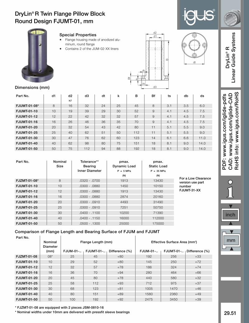
®DryLin® R Twin Flange Pillow BlockRound Design FJUMT-01, mm
Special Properties• Flange housing made of anodized alu-
minum, round flange
• Contains 2 of the JUM-02-XX liners
Part No.Nominal Flange Length (mm) Effective Surface Area (mm2)Diameter
(mm) FJUM-01-.. FJUMT-01-.. Difference (%) FJUM-01-.. FJUMT-01-.. Difference (%)
FJZMT-01-08 08* 25 45 +80 192 256 +33
FJUMT-01-10 10 29 52 +80 145 250 +72
FJUMT-01-12 12 32 57 +78 186 324 +74
FJUMT-01-16 16 36 70 +94 280 464 +66
FJUMT-01-20 20 45 80 +78 440 580 +32
FJUMT-01-25 25 58 112 +93 712 975 +37
FJUMT-01-30 30 68 123 +81 1005 1470 +46
FJUMT-01-40 40 80 151 +89 1580 2360 +49
FJUMT-01-50 50 100 192 +92 2475 3450 +39
Comparison of Flange Length and Bearing Surface of FJUM and FJUMT
Dimensions (mm)
Part No. d1 d2 d3 dt k B Bf ts db dsh7
FJUMT-01-08* 8 16 32 24 25 45 8 3.1 3.5 6.0
FJUMT-01-10 10 19 39 29 30 52 9 4.1 4.5 7.5
FJUMT-01-12 12 22 42 32 32 57 9 4.1 4.5 7.5
FJUMT-01-16 16 26 46 36 35 70 9 4.1 4.5 7.5
FJUMT-01-20 20 32 54 43 42 80 11 5.1 5.5 9.0
FJUMT-01-25 25 40 62 51 50 112 11 5.1 5.5 9.0
FJUMT-01-30 30 47 76 62 60 123 14 6.1 6.6 11.0
FJUMT-01-40 40 62 98 80 75 151 18 8.1 9.0 14.0
FJUMT-01-50 50 75 112 94 88 192 18 8.1 9.0 14.0
* FJZMT-01-08 are equipped with 2 pieces JSM-0810-16* Nominal widths under 10mm are delivered with pressfit sleeve bearings
Part No. Nominal Tolerance** pmax. pmax.Size Bearing Dynamic Load Static Load
Inner Diameter P = 5 MPa P = 35 MPa
(N) (N)
FJZMT-01-08* 8 .0320 - .0700 1913 13430
FJUMT-01-10 10 .0300 - .0880 1450 10150
FJUMT-01-12 12 .0300 - .0880 1913 13430
FJUMT-01-16 16 .0300 - .0880 2874 20160
FJUMT-01-20 20 .0300 - .0910 4493 31490
FJUMT-01-25 25 .0300 - .0910 7251 50750
FJUMT-01-30 30 .0400 - .1100 10200 71390
FJUMT-01-40 40 .0400 - .1150 16000 112000
FJUMT-01-50 50 .0500 - .1300 25000 175000
For a Low Clearanceversion use partnumber FJUMT-31-XX
d1d2
db
tsBf
d3ds
B
dt

®
29.52
Dry
Lin
®R
Lin
ear
Gu
ide
Sys
tem
s
Inte
rnet
: h
ttp
://w
ww
.igu
s.co
mem
ail:
sale
s@ig
us.
com
Qu
ickS
pec
: h
ttp
://w
ww
.igu
s.co
m/i
glid
e-q
uic
ksp
ec
Tele
ph
on
e1-
800-
521-
2747
Fax
1-
401-
438-
7270
DryLin® R Twin Flange Pillow Block Square Design FJUMT-02, mm
Special Properties• Flange housing made of anodized
aluminum, square flange
• Contains 2 of the JUM-02-XX liners
Comparison of Flange Length and Bearing Surface of FJUM and FJUMT
Dimensions (mm)
Load Data
* FJZMT-02-08 are equipped with 2 pieces JSM-0810-12* Nominal widths under 10mm are delivered with pressfit sleeve bearings
Part No.Nominal Flange Length (mm) Effective Surface Area (mm2)Diameter
(mm) FJUM-02-.. FJUMT-02-.. Difference (%) FJUM-02-.. FJUMT-02-.. Difference (%)
FJZMT-02-08 08* 25 45 +80 192 256 +33
FJUMT-02-10 10 29 52 +80 145 250 +72
FJUMT-02-12 12 32 57 +78 186 324 +74
FJUMT-02-16 16 36 70 +94 280 464 +66
FJUMT-02-20 20 45 80 +78 440 580 +32
FJUMT-02-25 25 58 112 +93 712 975 +37
FJUMT-02-30 30 68 123 +81 1005 1470 +46
FJUMT-02-40 40 80 151 +89 1580 2360 +49
FJUMT-02-50 50 100 192 +92 2475 3450 +39
Part No. d1 d2 d3 dt k B Bf ts db dsh7
FJUMT-02-08* 8 16 32 24 25 45 8 3.1 3.5 6.0
FJUMT-02-10 10 19 39 29 30 52 9 4.1 4.5 7.5
FJUMT-02-12 12 22 42 32 32 57 9 4.1 4.5 7.5
FJUMT-02-16 16 26 46 36 35 70 9 4.1 4.5 7.5
FJUMT-02-20 20 32 54 43 42 80 11 5.1 5.5 9.0
FJUMT-02-25 25 40 62 51 50 112 11 5.1 5.5 9.0
FJUMT-02-30 30 47 76 62 60 123 14 6.1 6.6 11.0
FJUMT-02-40 40 62 98 80 75 151 18 8.1 9.0 14.0
FJUMT-02-50 50 75 112 94 88 192 18 8.1 9.0 14.0
Part No. Nominal Tolerance** pmax. pmax.Size Bearing Dynamic Load Static Load
Inner Diameter P = 5 MPa P = 35 MPa
(N) (N)
FJZMT-02-08* 8 .0320 - .0700 1913 13430
FJUMT-02-10 10 .0300 - .0880 1450 10150
FJUMT-02-12 12 .0300 - .0880 1913 13430
FJUMT-02-16 16 .0300 - .0880 2874 20160
FJUMT-02-20 20 .0300 - .0910 4493 31490
FJUMT-02-25 25 .0300 - .0910 7251 50750
FJUMT-02-30 30 .0400 - .1100 10200 71390
FJUMT-02-40 40 .0400 - .1150 16000 112000
FJUMT-02-50 50 .0500 - .1300 25000 175000
For a Low Clearanceversion use partnumber FJUMT-32-XX
d1d2
db
tsBf
d3ds
B
dt

29.53
inch
mm
PD
F:
ww
w.ig
us.
com
/ig
lide-
pd
fsC
AD
: w
ww
.igu
s.co
m/i
glid
e-C
AD
Ro
HS
info
: w
ww
.igu
s.co
m/R
oH
S
Dry
Lin
®R
Lin
ear
Gu
ide
Sys
tem
s
®RQA - Quad block, Closed, mm
Standard Self-Aligning d D1 A H H1 W R N E S S1with OJUM-01 with OJUM-03
OQA-01-12 OQA-03-12 12 22 85 30 18 14 42 13 73 5.3 M6
OQA-01-16 OQA-03-16 16 26 100 35 22 17 54 13 88 5.3 M6
OQA-01-20 OQA-03-20 20 32 130 42 25 17 72 18 115 6.8 M8
OQA-01-25 OQA-03-25 25 40 160 51 30 21 88 22 140 9.0 M10
OQA-01-30 OQA-03-30 30 47 180 60 35 21 96 26 158 10.5 M12
OQA-01-40 OQA-03-40 40 62 230 77 45 27 122 34 202 13.5 M16
Standard Self-Aligning All Plastic d D1 A H H1 H3 R N E S S1with RJUM-01 with RJUM-03 with RJM-01
RQA-01-08 RQA-03-08 RQA-04-08 8 16 65 23 11.5 8 32 11 55 4.3 M5
RQA-01-12 RQA-03-12 RQA-04-12 12 22 85 32 16 13 42 13 73 5.3 M6
RQA-01-16 RQA-03-16 RQA-04-16 16 26 100 36 18 15 54 13 88 5.3 M6
RQA-01-20 RQA-03-20 RQA-04-20 20 32 130 46 23 19 72 18 115 6.6 M8
RQA-01-25 RQA-03-25 RQA-04-25 25 40 160 56 28 24 88 22 140 8.4 M10
RQA-01-30 RQA-03-30 RQA-04-30 30 47 180 64 32 27 96 26 158 10.5 M12
RQA-01-40 RQA-03-40 RQA-04-40 40 62 230 80 40 35 122 34 202 13.5 M16
OQA - Quad Block, Open, mm
M8x1
H
H1
N
A
d D1
H3
Quad block, with DryLin® Rlinear bearings
Dimensions (mm)
Dimensions (mm)
E A
R
Special Properties• Housing: aluminum
• Equipped with DryLin® R linear plain bearings,part no. RJUM-01-ø, RJUM-03-ø, or RJM-01
• Bearings are secured with retaining ringsaccording to DIN 472
• Mounting bolts DIN 912-8.8, lock washer DIN7980
S1
S
N
E A
R
Quad block open with DryLin® Rlinear bearings
d D1
W
60°
M8x1
H
H1
A
Special Properties• Housing: aluminum
• Equipped with DryLin® R linear plain bearings, Part no. OJUM-01-ø or OJUM-03-ø
• Maintenance-free
• Mounting bolts DIN 912-8.8, lock washer DIN 7980
• Securing of the bearing in the housing is done using set screws
S1
S
N
For a Low Clearance versionuse part number RQA-31-XX for standardRQA-33-XX for self-aligning
For a Low Clearance versionuse part number OQA-31-XX for standardOQA-33-XX for self-aligning
HTSPage30.17
Also available asdriven systems

®
29.54
Dry
Lin
®R
Lin
ear
Gu
ide
Sys
tem
s
Inte
rnet
: h
ttp
://w
ww
.igu
s.co
mem
ail:
sale
s@ig
us.
com
Qu
ickS
pec
: h
ttp
://w
ww
.igu
s.co
m/i
glid
e-q
uic
ksp
ec
Tele
ph
on
e1-
800-
521-
2747
Fax
1-
401-
438-
7270
RTA - Pillow Block, Closed, Twin Design, mm
Dimensions (mm)
OTA - Pillow Block, Open, Twin Design, mm
Pillow block ,twin design withDryLin® R linear plain bearings
Special Properties• Housing: aluminum
• Equipped with DryLin® R linear plain bearings, partno. RJUM-01-ø, RJUM-03-ø or. RJM-01
• Can be combined with DryLin® R housing bearing,Part No. RJUM-06-ø
• Bearings are secured with retaining rings accordingto DIN 472
• Mounting bolts DIN 912-8.8, lock washer DIN 7980
Pillow block, twin design, openwith DryLin® R linear plainbearings
Special Properties• Housing: aluminum
• Equipped with DryLin® R linear plain bearings, Part No.OJUM-01-ø or OJUM-03-ø
• Can be combined with DryLin® R housing bearing,Part No. OJUM-06-ø
• Securing of the bearing in the housing is done usingset screws
• Mounting bolts DIN 912-8.8, washer DIN 7980
Part No. d D H H1 H2 H3 H4 S1 B L M E1 E2 d1 d2Standard Self-Aligning All Plastic H6 +0.01 +0.3 ±0.02 ±0.15 ±0.15
with RJUM-01 with RJUM-03 with RJM-0 -0.02
RTA-01-08 – RTA-04-08 8 16 28 13 13 8 14 M 5 35 62 17.5 35 25 4.20 8
RTA-01-12 RTA-03-12 RTA-04-12 12 22 35 18 13 10 25 M 6 43 76 21.5 40 30 5.20 10
RTA-01-16 RTA-03-16 RTA-04-16 16 26 42 22 13 12 30 M 6 53 84 26.5 45 36 5.20 10
RTA-01-20 RTA-03-20 RTA-04-20 20 32 50 25 18 13 24 M 8 60 104 30.0 55 45 6.80 11
RTA-01-25 RTA-03-25 RTA-04-25 25 40 60 30 22 15 40 M10 78 130 39.0 70 54 8.60 15
RTA-01-30 RTA-03-30 RTA-04-30 30 47 70 35 26 16 48 M12 87 152 43.5 85 62 10.30 18
RTA-01-40 RTA-03-40 RTA-04-40 40 62 90 45 34 20 60 M16 108 176 54.0 100 80 14.25 20
Dimensions (mm)
Part No. d D H H1 H2 H3 H4 S1 B L M E1 E2 d1 d2 WStandard Self-Aligning H6 +0.01 +0.3 ±0.02 ±0.15 ±0.15
with OJUM-01 with OJUM-03 -0.02
OTA-01-12 OTA-03-12 12 22 30 18 13 10 25 M 6 43 76 21.5 40 30 5.20 10 14
OTA-01-16 OTA-03-16 16 26 35 22 13 12 30 M 6 53 84 26.5 45 36 5.20 10 17
OTA-01-20 OTA-03-20 20 32 42 25 18 13 24 M 8 60 104 30.0 55 45 6.80 11 17
OTA-01-25 OTA-03-25 25 40 51 30 22 15 40 M10 78 130 29.0 70 54 8.60 15 21
OTA-01-30 OTA-03-30 30 47 60 35 26 16 48 M12 87 152 43.5 85 62 10.30 18 21
OTA-01-40 OTA-03-40 40 62 77 45 34 20 60 M16 108 176 54.0 100 80 14.25 20 27
For a Low Clearance versionuse part number RTA-31-XX for standardRTA-33-XX for self-aligning
For a Low Clearance versionuse part number OTA-31-XX for standardOTA-33-XX for self-aligning

29.55
inch
mm
PD
F:
ww
w.ig
us.
com
/ig
lide-
pd
fsC
AD
: w
ww
.igu
s.co
m/i
glid
e-C
AD
Ro
HS
info
: w
ww
.igu
s.co
m/R
oH
S
Dry
Lin
®R
Lin
ear
Gu
ide
Sys
tem
s
®RGA Pillow Block, Closed, Long Design, mm
OGA Pillow Block, Open, Long Design, mm
Special Properties• Housing: aluminum
• Equipped with DryLin® R linear plain bearings, Part No. RJUM-01-ø, RJUM-03-ø or RJM-01
• Can be combined with DryLin® R housing bearing, Part No. RJUM-06-ø
• Bearings are secured with retaining rings according to DIN 472
Special Properties• Housing: aluminum
• Equipped with DryLin® linear plain bearings OJUM-01-øor OJUM-03-ø
• Can be combined with DryLin® R housing bearingOJUM-06-ø
• Bearings are secured with retaining rings according toDIN 472
Part No. d D H H1 H2 H3 H4 S1 B L M E1 E2 d1 d2Standard Self-Aligning All Plastic H6 +0.01 ±0.03 ±0.15 ±0.15
with RJUM-01 with RJUM-03 with RJM-01 -0.02
RGA-01-08 – RGA-04-08 8 16 28 13 10 8 14 M 4 35 32 17.5 20 25 3.2 6
RGA-01-12 RGA-03-12 RGA-04-12 12 22 35 18 11 10 25 M 5 43 39 21.5 23 32 4.2 6
RGA-01-16 RGA-03-16 RGA-04-16 16 26 42 22 13 12 30 M 6 53 43 26.5 26 40 5.2 10
RGA-01-20 RGA-03-20 RGA-04-20 20 32 50 25 18 13 24 M 8 60 54 30.0 32 45 6.8 11
RGA-01-25 RGA-03-25 RGA-04-25 25 40 60 30 22 15 40 M10 78 67 39.0 40 60 8.6 15
RGA-01-30 RGA-03-30 RGA-04-30 30 47 70 35 22 16 48 M10 87 79 43.5 45 68 8.6 15
RGA-01-40 RGA-03-40 RGA-04-40 40 62 90 45 26 20 60 M12 108 91 54.0 58 86 10.3 18
Dimensions (mm)
Dimensions (mm)
Part No.. Self- d D H H1 H2 H3 H4 S1 B L M E1 E2 d1 d2 WStandard Self-Aligning H6 +0.01 +0.3 ±0.03 ±0.15 ±0.15 +0.6
with OJUM-01 with OJUM-03 -0.02
OGA-01-12 OGA-03-12 12 22 28 18 11 8 25 M 5 43 39 21.5 23 32 4.2 8 14
OGA-01-16 OGA-03-16 16 26 35 22 13 12 30 M 6 53 43 26.5 26 40 5.2 10 17
OGA-01-20 OGA-03-20 20 32 42 25 18 13 24 M 8 60 54 30.0 32 45 6.8 11 17
OGA-01-25 OGA-03-25 25 40 51 30 22 15 40 M10 78 67 39.0 40 60 8.6 15 21
OGA-01-30 OGA-03-30 30 47 60 35 22 16 48 M10 87 79 43.5 45 68 8.6 15 21
OGA-01-40 OGA-03-40 40 62 77 45 26 20 60 M12 108 91 54.0 58 86 10.3 18 27
For a Low Clearance versionuse part number RGA-31-XX for standardRGA-33-XX for self-aligning
For a Low Clearance versionuse part number OGA-31-XX for standardOGA-33-XX for self-aligning

®
29.56
Dry
Lin
®R
Lin
ear
Gu
ide
Sys
tem
s
Inte
rnet
: h
ttp
://w
ww
.igu
s.co
mem
ail:
sale
s@ig
us.
com
Qu
ickS
pec
: h
ttp
://w
ww
.igu
s.co
m/i
glid
e-q
uic
ksp
ec
Tele
ph
on
e1-
800-
521-
2747
Fax
1-
401-
438-
7270
OGAS Pillow Block, Open, Short Design, mm
A2
H1
H2
H
øS
ød
øD
A
A1
E
E1
Special Properties• Housing: aluminum
• Equipped with DryLin® R linear plain bearings, Part No. RJUM-01-ø, RJUM-03-ø or RJM-01
• Can be combined with DryLin® R housing bearing RJUM-06-ø
• Bearings are secured with retaining rings according to DIN 472
ød
A2(° )
E3
HH
1
øD
øS
H2
A1A
E
E1
Special Properties• Housing: aluminum
• Equipped with DryLin® R linear plain bearings, Part No.OJUM-01-ø or OJUM-03-ø
• Can be combined with DryLin® R housing bearing, Part No.OJUM-06-ø
• Securing of the bearing in the housing is done using setscrews
Dimensions (mm)
Dimensions (mm)
Part No. d D H H1 A A1 A2 E E1 SStandard Self-Aligning All Plasticwith RJUM-01 with RJUM-03 with RJM-01
RGAS-01-12 RGAS-03-12 RGAS-04-12 12 22 18 35 52 42 30 20 10 5.3
RGAS-01-16 RGAS-03-16 RGAS-04-16 16 26 22 40.5 56 46 34 22 11 5.3
RGAS-01-20 RGAS-03-20 RGAS-04-20 20 32 25 48.0 70 58 40 28 14 6.4
RGAS-01-25 RGAS-03-25 RGAS-04-25 25 40 30 58.0 80 68 50 40 20 6.4
RGAS-01-30 RGAS-03-30 RGAS-04-30 30 47 35 67.0 88 76 58 48 24 6.4
RGAS-01-40 RGAS-03-40 RGAS-04-40 40 62 45 85.0 108 94 74 56 28 8.4
Part No. d D H H1 A A1 A2 E E1 E3 ( º ) SStandard Self-Aligningwith OJUM-01 with OJUM-03
OGAS-01-12 OGAS-03-12 12 22 18 28 52 42 30 20 10 14 78 5.3
OGAS-01-16 OGAS-03-16 16 26 22 33.5 56 46 34 22 11 17 78 5.3
OGAS-01-20 OGAS-03-20 20 32 25 42 70 58 40 28 14 17 60 6.4
OGAS-01-25 OGAS-03-25 25 40 30 51 80 68 50 40 20 21 60 6.4
OGAS-01-30 OGAS-03-30 30 47 35 60 88 76 58 48 24 21 54 6.4
OGAS-01-40 OGAS-03-40 40 62 45 77 108 94 74 56 28 27 54 8.4
For a Low Clearance versionuse part number RGAS-31-XX for standardRGAS-33-XX for self-aligning
For a Low Clearance versionuse part number OGAS-31-XX for standardOGAS-33-XX for self-aligning
RGAS Pillow Block, Closed, Short Design, mm