drywall metal systems - ciprianidrywall.co.uk drywall metal... · cipriani 1. drywall metal...
TRANSCRIPT

Drywall Metal Systems
CIPRIANI DRYWALL METAL SYSTEMS

1CIPRIANI DRYWALL METAL SYSTEMS
Index
GENERAL INFORMATION
SYSTEMS PROFILE UKC-Studs for Walls - I-Studs for WallsU-Track for WallsCeilings - MF SystemsCeilings - Ceiling lining System
L-SHAPED PROFILES OMEGA PROFILES STAFF ANGLES EDFE BEADL-Shaped profiles - Omega profiles - Channel for OmegaStaff angles edge bead
FLEX PROFILESFlex profiles
CLP PROFILES FOR PRIMARY STRUCTURESCLP profiles for primary structures
ACCESSORIESAccessories SystemAccessories for CD5027 Accessories - Brackets - Squared + Accessories - Hanging rodsAccessories CLP primary structures
METAL GRID SUSPENSION SYSTEMS FOR SUSPENDED CEILINGSHD24 SystemST24 SystemCR24 SystemHD15 SystemHD35 SystemBE24 SystemSV24 SystemL-W-F Perimeter profiles - Special profilesGYPS42 System
page 3
page 8page 9
page 14page 15
page 20page 21
page 25
page 29
page33page 34page 35page 36
page 40page 43page 46page 49page 52page 55page 58page 61page 64


3CIPRIANI DRYWALL METAL SYSTEMS
General Information
INTRODUCTION
To trace the CIPRIANI family back to its origins, in the city of Rovereto, in Trentino region,
we have to go back to the first years of 19th century. The family committed itself to industrial
production in several fields such as chemistry, engineering, food, printing and publishing. In
1961, CIPRIANI started off the manufacturing of cold formed profiles for building industry,
a brand new product at the time. By the middle of 1970s the final decision: all the attention
was focused on the production of metal systems for plasterboard and suspended ceilings.
Today, CIPRIANI PROFILATI is still a family-owned business company arrived at its fourth
generation and yet it steadily maintains the market leadership in this field.
The whole production is carried out in the new factory situated in Rovereto (Italy) industrial
area. The factory stands on a 40.000 sqm area, of which 20.000 sqm are covered. The site
has been built in a strategic position, at about 1 km from the A22 “Rovereto Sud” highway
junction and close to the railway goods yard.
Through the continuous research and the development at the company’s own laboratories,
unique production technology has been developed and is protected by several international
patents, CIPRIANI has achieved quality and quantity standards of absolute excellence.
The company is made up of a team of professional engineers and business people who are
ready to work proactively and positively in the market.
At home and abroad, CIPRIANI PROFILATI is known for quality, reliability and professionalism,
our distribution network is helped by our high level of service.
Thanks to its corporate identity, CIPRIANI PROFILATI has gained the confidence of its
customers and over time become an invaluable business partner.
SYSTEM CERTIFICATION:UNI EN ISO 9001
(SGS certificate n° IT 07/1415)
PRODUCTS CERTIFICATION:CE marking according toStandards DIN EN 14195
PRODUCTS CERTIFICATION:NF Certification
According to AFAQ AFNOR NF 411
Adherent Member of
Cipriani Profilati complies with and meets the requirements of Regulation (EU) No 305/2011 OF THE EUROPEAN PARLIAMENT AND OF THE COUNCIL of 9 March 2011 laying down harmonized conditions for the marketing of construction products and repealing Council Directive 89/106/EEC.
CERT
IFIÉ PAR CSTB
PRODUCTS CERTIFICATIONS
4 CIPRIANI DRYWALL METAL SYSTEMS
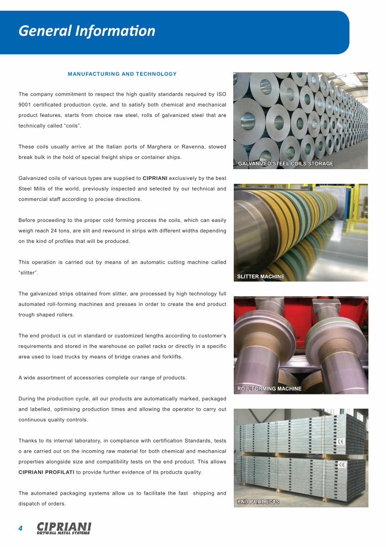
MANUFACTURING AND TECHNOLOGY
The company commitment to respect the high quality standards required by ISO
9001 certificated production cycle, and to satisfy both chemical and mechanical
product features, starts from choice raw steel, rolls of galvanized steel that are
technically called “coils”.
These coils usually arrive at the Italian ports of Marghera or Ravenna, stowed
break bulk in the hold of special freight ships or container ships.
Galvanized coils of various types are supplied to CIPRIANI exclusively by the best
Steel Mills of the world, previously inspected and selected by our technical and
commercial staff according to precise directions.
Before proceeding to the proper cold forming process the coils, which can easily
weigh reach 24 tons, are slit and rewound in strips with different widths depending
on the kind of profiles that will be produced.
This operation is carried out by means of an automatic cutting machine called
“slitter”.
The galvanized strips obtained from slitter, are processed by high technology full
automated roll-forming machines and presses in order to create the end product
trough shaped rollers.
The end product is cut in standard or customized lengths according to customer’s
requirements and stored in the warehouse on pallet racks or directly in a specific
area used to load trucks by means of bridge cranes and forklifts.
A wide assortment of accessories complete our range of products.
During the production cycle, all our products are automatically marked, packaged
and labelled, optimising production times and allowing the operator to carry out
continuous quality controls.
Thanks to its internal laboratory, in compliance with certification Standards, tests
o are carried out on the incoming raw material for both chemical and mechanical
properties alongside size and compatibility tests on the end product. This allows
CIPRIANI PROFILATI to provide further evidence of its products quality.
The automated packaging systems allow us to facilitate the fast shipping and
dispatch of orders.
General Information
GALVANIZED STEEL COILS STORAGE
SLITTER MACHINE
ROLLFORMING MACHINE
END PRODUCTS
5CIPRIANI DRYWALL METAL SYSTEMS
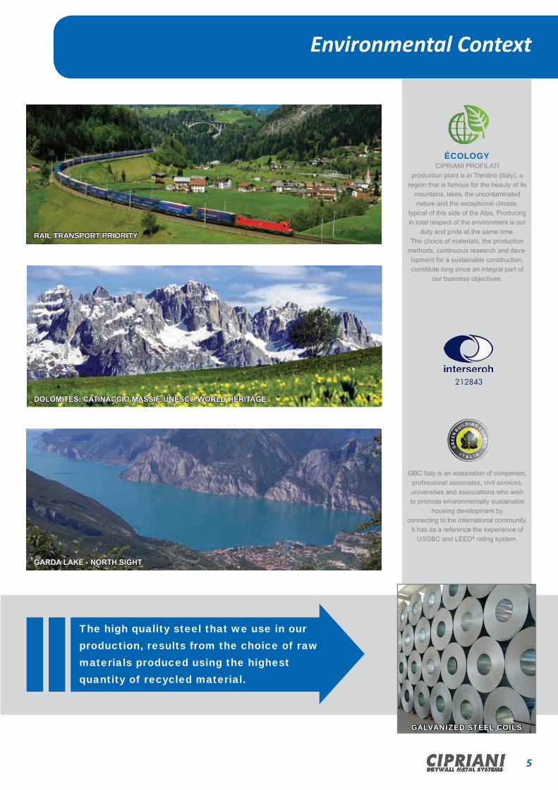
Environmental Context
The high quality steel that we use in our production, results from the choice of raw materials produced using the highest quantity of recycled material.
RAIL TRANSPORT PRIORITY
GARDA LAKE - NORTH SIGHT
DOLOMITES: CATINACCIO MASSIF, UNESCO WORLD HERITAGE
ÉCOLOGYCIPRIANI PROFILATI
production plant is in Trentino (Italy), a region that is famous for the beauty of its
mountains, lakes, the uncontaminated nature and the exceptional climate,
typical of this side of the Alps. Producing in total respect of the environment is our
duty and pride at the same time. The choice of materials, the production
methods, continuous research and deve-lopment for a sustainable construction, constitute long since an integral part of
our business objectives.
GBC Italy is an association of companies, professional associates, civil services, universities and associations who wish to promote environmentally sustainable
housing development by connecting to the international community.
It has as a reference the experience of USGBC and LEED® rating system.
212843
GALVANIZED STEEL COILS

SYSTEMS PROFILES UK

8 CIPRIANI DRYWALL METAL SYSTEMS
SECTION PROFILE CODE DIMENSIONS (mm) PACK SIZE
C-StudThickness 0,50mm
4850607092146
KC483405KC503405KC603405KC703405KC923405KC1463405
4850607092146
32 34 120 12 no packs x 10 no lengths
C-StudThickness 0,60mm
7092
KC703406KC923406
7092
32 34 120 12 no packs x 10 no lengths
C-StudThickness 0,70mm
70146
KC703407KC1463407
70146
32 34 120 12 no packs x 10 no lengths
C-StudThickness 0,10mm 92 KC923410 92 32 34 120 12 no packs x
10 no lengths
32 34
BASE
0,50g f
Base SideDescription Number of piecesSide
32 34
BASE
C-Studs for Walls
SECTION PROFILE CODE DIMENSIONS (mm) PACK SIZE
I-StudThickness 0,50mm
48506070
KI483805KI503805KI603805KI703805
5060
38
I-StudThickness 0,70mm
6070
KI603807KI703807
70 38
I-StudThickness 0,90mm
92146
KI923809KI1463809
92146
3838
BaseDescription Number of piecesSide
I-Studs for Walls
32 34
BASE
0,60g f
32 34
BASE
1,00g f
0,50g f
0,70g f
0,70g f
0,90g f
TITOLO
1 di 1
A. Esposito 03/04/2013Disegnato Controllato Approvato Data
Revisione Foglio
CLP
CLASSE DI TOLLERANZA GENERALE (mm): Designazionesecondo UNI EN ISO 22768 - Scostamenti limite ammessiper campi di dimensioni nominali lineari - CLASSE FINE
L>=0.5L<=3± 0.05
L>30L<=120± 0.15
L>3L<=6± 0.05
L>6L<=30± 0.1
L>120L<=400± 0.2
L>1000L<=2000± 0.5
L>400L<=1000± 0.3
L>2000L<=4000± 1.0
Scala
--
Cipriani Profilati s.r.l. - Ogni diritto sui contenuti del presente disegno è riservato ai sensi dellanormativa vigente. La sua riproduzione, la pubblicazione e la distribuzione, totale o parziale,(tra cui, a titolo esemplificativo e non esaustivo, i testi, le immagini, i disegni grafici) sonoespressamente vietate in assenza di autorizzazione scritta da parte dell'azienda sopra citata.
Codice disegnoCIPRIANI PROFILATI s.r.l. - Via Pineta,31 - 38068 Rovereto (TN) ItalyP.Iva 01173470228 - Tel. +39 0464 421412 - Fax. +39 0464 431330
E-mail: [email protected] - Web: www.ciprianiprofilati.it
Toll. Angolare± 0.1°
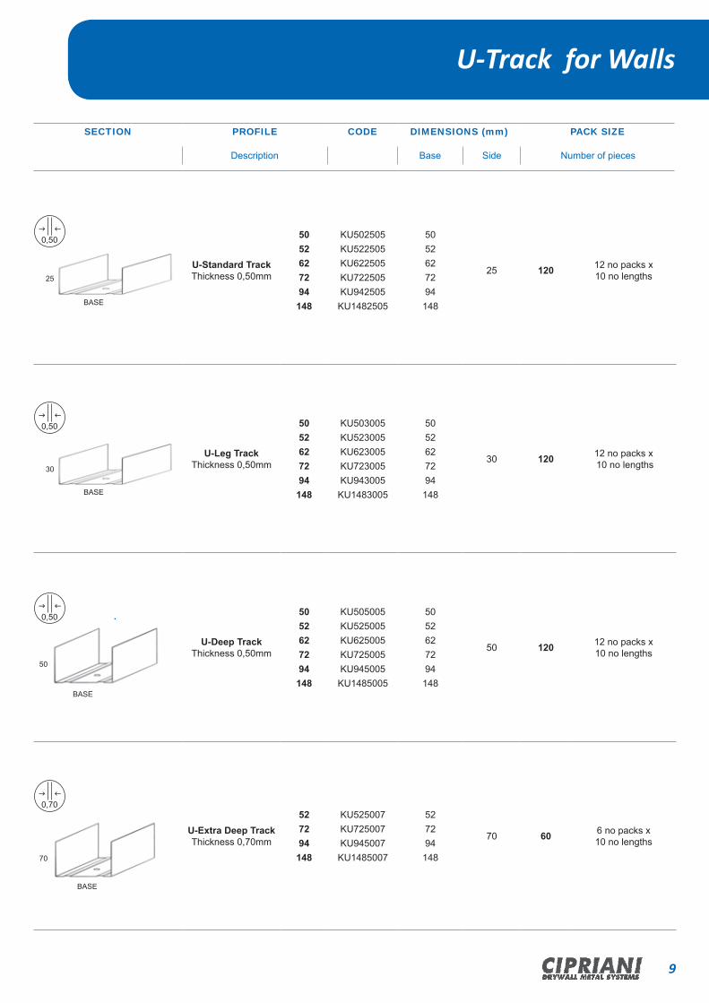
9CIPRIANI DRYWALL METAL SYSTEMS
SECTION PROFILE CODE DIMENSIONS (mm) PACK SIZE
U-Standard TrackThickness 0,50mm
5052627294148
KU502505KU522505KU622505KU722505KU942505KU1482505
5052627294148
25 120 12 no packs x 10 no lengths
U-Leg TrackThickness 0,50mm
5052627294148
KU503005KU523005KU623005KU723005KU943005KU1483005
5052627294148
30 120 12 no packs x 10 no lengths
U-Deep TrackThickness 0,50mm
5052627294148
KU505005KU525005KU625005KU725005KU945005KU1485005
5052627294148
50 120 12 no packs x 10 no lengths
U-Extra Deep TrackThickness 0,70mm
527294148
KU525007KU725007KU945007KU1485007
527294148
70 60 6 no packs x 10 no lengths
BaseDescription Number of piecesSide
BASE
25
BASE
30
0,50g f
0,50g f
0,50g f
U-Track for Walls
BASE
70
0,70g f
BASE
50
C-Studs for Walls
I-Studs for Walls
10 CIPRIANI DRYWALL METAL SYSTEMS
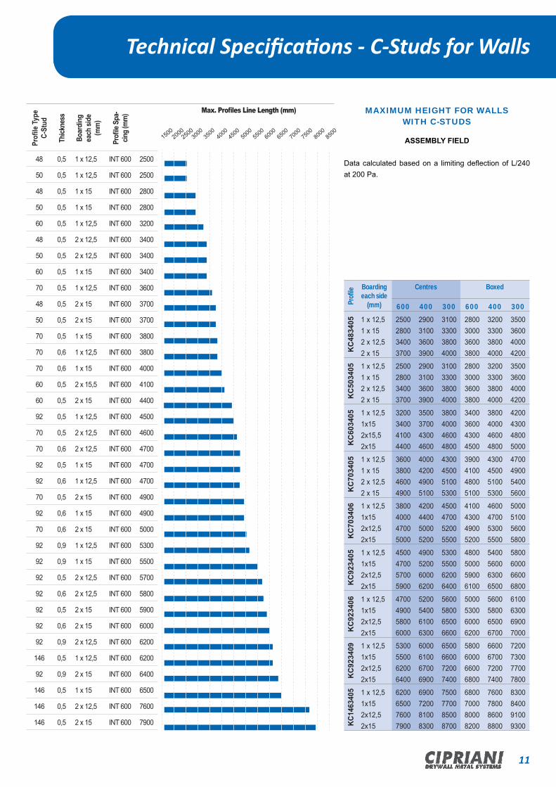
Technical Specifications - C-Studs for Walls Technical Specifications - PARTITION WALLS
32
4
23
32
1
2
3
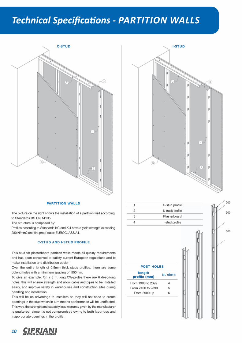
PARTITION WALLS
The picture on the right shows the installation of a partition wall according to Standards BS EN 14195.The structure is composed by:Profiles according to Standards KC and KU have a yield strength exceeding 280 N/mm2 and fire proof class: EUROCLASS A1.
C-STUD AND I-STUD PROFILE
This stud for plasterboard partition walls meets all quality requirements and has been conceived to satisfy current European regulations and to make installation and distribution easier.Over the entire length of 0,5mm thick studs profiles, there are some oblong holes with a minimum spacing of 500mm.To give an example: On a 3 m. long CW-profile there are 6 deep-long holes, this will ensure strength and allow cable and pipes to be installed easily, and improve safety in warehouses and construction sites during handling and installation.This will be an advantage to installers as they will not need to create openings in the stud which in turn means performance will be unaffected.This way, the strength and capacity load warranty given by the manufacturer is unaltered, since it’s not compromised owing to both laborious andinappropriate openings in the profile.
200
500
500
POST HOLES
length profile (mm) N. slots
From 1900 to 2399 From 2400 to 2899
From 2900 up
456
C-STUD I-STUD
1 C-stud profile
2 U-track profile
3 Plasterboard
4 I-stud profile
11CIPRIANI DRYWALL METAL SYSTEMS
Prof
ile Boarding each side
(mm)
Centres Boxed
600 400 300 600 400 300
KC
4834
05 1 x 12,51 x 152 x 12,52 x 15
2500280034003700
2900310036003900
3100330038004000
2800300036003800
3200330038004000
3500360040004200
KC
5034
05 1 x 12,51 x 152 x 12,52 x 15
2500280034003700
2900310036003900
3100330038004000
2800300036003800
3200330038004000
3500360040004200
KC
6034
05 1 x 12,51x152x15,52x15
3200340041004400
3500370043004600
3800400046004800
3400360043004500
3800400046004800
4200430048005000
KC
7034
05 1 x 12,51 x 152 x 12,52 x 15
3600380046004900
4000420049005100
4300450051005300
3900410048005100
4300450051005300
4700490054005600
KC
7034
06 1 x 12,51x152x12,52x15
3800400047005000
4200440050005200
4500470052005500
4100430049005200
4600470053005500
5000510056005800
KC
9234
05 1 x 12,51x152x12,52x15
4500470057005900
4900520060006200
5300550062006400
4800500059006100
5400560063006500
5800600066006800
KC
9234
06 1 x 12,51x152x12,52x15
4700490058006000
5200540061006300
5600580065006600
5000530060006200
5600580065006700
6100630069007000
KC
9234
09 1 x 12,51x152x12,52x15
5300550062006400
6000610067006900
6500660072007400
5800600066006800
6600670072007400
7200730077007800
KC14
6340
5 1 x 12,51x152x12,52x15
6200650076007900
6900720081008300
7500770085008700
6800700080008200
7600780086008800
8300840091009300
Profi
le Ty
pe
C-St
ud
Thick
ness
Boar
ding
ea
ch si
de(m
m)
Profi
le Sp
a-cin
g (m
m)
48 0,5 1 x 12,5 INT 600 2500
50 0,5 1 x 12,5 INT 600 2500
48 0,5 1 x 15 INT 600 2800
50 0,5 1 x 15 INT 600 2800
60 0,5 1 x 12,5 INT 600 3200
48 0,5 2 x 12,5 INT 600 3400
50 0,5 2 x 12,5 INT 600 3400
60 0,5 1 x 15 INT 600 3400
70 0,5 1 x 12,5 INT 600 3600
48 0,5 2 x 15 INT 600 3700
50 0,5 2 x 15 INT 600 3700
70 0,5 1 x 15 INT 600 3800
70 0,6 1 x 12,5 INT 600 3800
70 0,6 1 x 15 INT 600 4000
60 0,5 2 x 15,5 INT 600 4100
60 0,5 2 x 15 INT 600 4400
92 0,5 1 x 12,5 INT 600 4500
70 0,5 2 x 12,5 INT 600 4600
70 0,6 2 x 12,5 INT 600 4700
92 0,5 1 x 15 INT 600 4700
92 0,6 1 x 12,5 INT 600 4700
70 0,5 2 x 15 INT 600 4900
92 0,6 1 x 15 INT 600 4900
70 0,6 2 x 15 INT 600 5000
92 0,9 1 x 12,5 INT 600 5300
92 0,9 1 x 15 INT 600 5500
92 0,5 2 x 12,5 INT 600 5700
92 0,6 2 x 12,5 INT 600 5800
92 0,5 2 x 15 INT 600 5900
92 0,6 2 x 15 INT 600 6000
92 0,9 2 x 12,5 INT 600 6200
146 0,5 1 x 12,5 INT 600 6200
92 0,9 2 x 15 INT 600 6400
146 0,5 1 x 15 INT 600 6500
146 0,5 2 x 12,5 INT 600 7600
146 0,5 2 x 15 INT 600 7900
Max. Profiles Line Length (mm)
15002000
250030
0035
0040
0045
0050
0055
0060
0065
0070
0075
0080
0085
00
Technical Specifications - C-Studs for Walls
MAXIMUM HEIGHT FOR WALLS WITH C-STUDS
ASSEMBLY FIELD
Data calculated based on a limiting deflection of L/240 at 200 Pa.
Technical Specifications - PARTITION WALLS

12 CIPRIANI DRYWALL METAL SYSTEMS
Technical Specifications - I-Studs for Walls
Prof
ile
Boarding each side
(mm)
Centres
600 400 300K
I483
805 1 x 12,5
1 x 152 x 12,52 x 15
290031003700 3900
3400350039004200
3700380042004400
KI5
0380
5 1 x 12,51 x 152 x 12,52 x 15
290031003700 3900
3400350039004200
3700380042004400
KI6
0380
5 1 x 12,51x152x12,52x15
3600380044004600
4000420047004900
4400450050005200
KI6
0380
7 1 x 12,51 x 152 x 12,52 x 15
4100420047004900
4600470051005300
5000510055005600
KI7
0380
5 1 x 12,51x152x12,52x15
4100430049005200
4600470053005500
5000510056005800
KI7
0380
7 1 x 12,51x152x12,52x15
4600470053005500
5100530057005900
5600570061006300
KI9
2380
9 1 x 12,51x152x12,52x15
6000610068006900
6800690074007500
7400750079008000
KI14
6380
9 1 x 12,51x152x12,52x15
7900810088009000
8900900096009800
970098001040010500
Profi
le Ty
pe
Thick
ness
Board
ing
each
side
(mm)
Profi
le Sp
acing
(m
m)
48 0,5 1 x 12,5 INT 600 2900
50 0,5 1 x 12,5 INT 600 2900
48 0,5 1 x 15 INT 600 3100
50 0,5 1 x 15 INT 600 3100
60 0,5 1 x 12, INT 600 3600
48 0,5 2 x 12,5 INT 600 3700
50 0,5 2 x 12,5 INT 600 3700
60 0,5 1 x 15 INT 600 3800
48 0,5 2 x 15 INT 600 3900
50 0,5 2 x 15 INT 600 3900
60 0,7 1 x 12,5 INT 600 4100
70 0,5 1 x 12,5 INT 600 4100
60 0,7 1 x 15 INT 600 4200
70 0,5 1 x 15 INT 600 4300
60 0,5 2 x 12,5 INT 600 4400
60 0,5 2 x 15 INT 600 4600
70 0,7 1 x 12,5 INT 600 4600
60 0,7 2 x 12,5 INT 600 4700
70 0,7 1 x 15 INT 600 4700
60 0,7 2 x15 INT 600 4900
70 0,5 2 x 12,5 INT 600 4900
70 0,5 2 x 15 INT 600 5200
70 0,7 2 x 12,5 INT 600 5300
70 0,7 2 x 15 INT 600 5500
92 0,9 1 x 12,5 INT 600 6000
92 0,9 1 x 15 INT 600 6100
92 0,9 2 x 12,5 INT 600 6800
92 0,9 2 x 15 INT 600 6900
146 0,9 1 x 12,5 INT 600 8400
146 0,9 1 x 15 INT 600 8500
146 0,9 2 x 12,5 INT 600 9100
146 0,9 2 x 15 INT 600 9400
Max. Profiles Line Length (mm)
25003000
35004000
45005000
55006000
65007000
75008000
85009000
9500
MAXIMUM HEIGHT FOR WALLS WITH I-STUDS
ASSEMBLY FIELD
Data calculated based on a limiting deflection of L/240 at 200 Pa.

13CIPRIANI DRYWALL METAL SYSTEMS
INDICATIVE INCIDENCE PER SQM
Ref. Profile Description Incidence per sqm
1 CD451805C 45x18 Profile
orC 48x18Profile
2 ml
2 UD201805 U 20x18x28 Channel Varies depending on walls length
3 C.126C.129C.130C.131
Adjustable Bracket 2 pieces
4 Plasterboard
INDICATIVE INCIDENCE PER SQM
Ref. Profile Description Incidence per sqm
1 CW C-Shaped Profile 2 m l
2 UW U-Shaped Channel Varies depending on walls length
3 C.010C.069
Wall Square 70x35Wall Square 120x35 2 pieces
4 Plasterboard
The following drawings show two possible assembly methods for wall linings with metal profiles according to Standards BS EN14195. These profiles according to standards CE have a yield strength exceeding 280 N/sq mm and fire proof class: EUROCLASS A1.
Technical Specifications WALLS LINING
4
1
2
3
≤120
0
2
4
≤120
0
1
3
Max. Spacing between profiles 600 mm Max. Spacing between profiles 600 mm
Technical Specifications - I-Studs for Walls

14 CIPRIANI DRYWALL METAL SYSTEMS
SECTION PROFILE CODE DIMENSIONS (mm) PACK SIZE
Ceiling Furring - MF5Thickness 0,50mm KO522605 52 26 26 200 20 no packs x
10 no lengths
Perimeter Channel -MF6Thickness 0,50mm KD282005 27 28 20 300 30 no packs x
10 no lengths
Primary Channel - MF7Thickness 0,90mm KD451509 45 15 15 250 25 no packs x
10 no lengths
BaseDescription Number of piecesSide
52
0,50g f
26
15
45
28
20
28
Side
ACCESSORY: code description page number reference
LW252505 Angle 63
Ceilings - MF System
0,90g f

15CIPRIANI DRYWALL METAL SYSTEMS
Ceilings - Ceiling Lining System
SECTION PROFILE CODE DIMENSIONS (mm) PACK SIZE
Wall/Ceiling LinerThickness 0,50mm 45 CD451805 45 18 18 200 20 no packs x
10 no lengths
Perimeter TrackThickness 0,50mm 20 UD201805 20 28 18 200 12 no packs x
10 no lengths
BaseDescription Number of piecesSide
20
18
28
Side
ACCESSORY: code description page number reference
F.203F.204F.205F.206F.207F.208
Reinforced
Suspensions
80 mm Length
180 mm Length
240 mm Length
320 mm Length
400 mm Length
480 mm Length
33
C.129C.126C.130C.131
Fixing Bracket
50x80 mm50x120 mm50x60 mm50x40 mm
35
F.201 Wall/Ceiling liner Connector 33
18
45

16 CIPRIANI DRYWALL METAL SYSTEMS
Technical SpecificationCeilings MF SYSTEM
CEILING TOTAL WEIGHT (A) SUSPENSION HANGER CENTRES (mm)
Less than 15 1200
CEILING TOTAL WEIGHT (B) MF PRIMARY SUPPORT CHANNEL CENTRES (MM)
Between 15 and 30Between 35 and 40Between 45 and 50
1200900600
CEILING TOTAL WEIGHT (C) MF CEILING CHANNEL CENTRES (MM)
Less than 15 450
BA
C
6
1
2
4
3
5
100
1 CEILING FURRING
2 PRIMARY CHANNEL
3 HANGER
4 PRE-FORMED CLIPS
5 PERIMETER CHANNEL
6 PLASTERBOARD
1/3A
Omega 150
1 di 1
A. Esposito 03/04/2013Disegnato Controllato Approvato Data
Revisione Foglio
2013-005-00044-A
CLASSE DI TOLLERANZA GENERALE (mm): Designazionesecondo UNI EN ISO 22768 - Scostamenti limite ammessiper campi di dimensioni nominali lineari - CLASSE FINE
L>=0.5L<=3± 0.05
L>30L<=120± 0.15
L>3L<=6± 0.05
L>6L<=30± 0.1
L>120L<=400± 0.2
L>1000L<=2000± 0.5
L>400L<=1000± 0.3
L>2000L<=4000± 1.0
Scala
Cipriani Profilati s.r.l. - Ogni diritto sui contenuti del presente disegno è riservato ai sensi dellanormativa vigente. La sua riproduzione, la pubblicazione e la distribuzione, totale o parziale,(tra cui, a titolo esemplificativo e non esaustivo, i testi, le immagini, i disegni grafici) sonoespressamente vietate in assenza di autorizzazione scritta da parte dell'azienda sopra citata.
Codice disegnoCIPRIANI PROFILATI s.r.l. - Via Pineta,31 - 38068 Rovereto (TN) ItalyP.Iva 01173470228 - Tel. +39 0464 421412 - Fax. +39 0464 431330
E-mail: [email protected] - Web: www.ciprianiprofilati.it
Toll. Angolare± 0.1°
UB 150
1 di 1
A. Esposito 03/04/2013Disegnato Controllato Approvato Data
Revisione Foglio
2013-005-00045-A
CLASSE DI TOLLERANZA GENERALE (mm): Designazionesecondo UNI EN ISO 22768 - Scostamenti limite ammessiper campi di dimensioni nominali lineari - CLASSE FINE
L>=0.5L<=3± 0.05
L>30L<=120± 0.15
L>3L<=6± 0.05
L>6L<=30± 0.1
L>120L<=400± 0.2
L>1000L<=2000± 0.5
L>400L<=1000± 0.3
L>2000L<=4000± 1.0
Scala
--
Cipriani Profilati s.r.l. - Ogni diritto sui contenuti del presente disegno è riservato ai sensi dellanormativa vigente. La sua riproduzione, la pubblicazione e la distribuzione, totale o parziale,(tra cui, a titolo esemplificativo e non esaustivo, i testi, le immagini, i disegni grafici) sonoespressamente vietate in assenza di autorizzazione scritta da parte dell'azienda sopra citata.
Codice disegnoCIPRIANI PROFILATI s.r.l. - Via Pineta,31 - 38068 Rovereto (TN) ItalyP.Iva 01173470228 - Tel. +39 0464 421412 - Fax. +39 0464 431330
E-mail: [email protected] - Web: www.ciprianiprofilati.it
Toll. Angolare± 0.1°
To join primary channels with nuts and bolts the minimum
overlap is 150mm.
To join furring sections overlap by at least 150mm and either crimp or screw fix both sides in two places.
17CIPRIANI DRYWALL METAL SYSTEMS
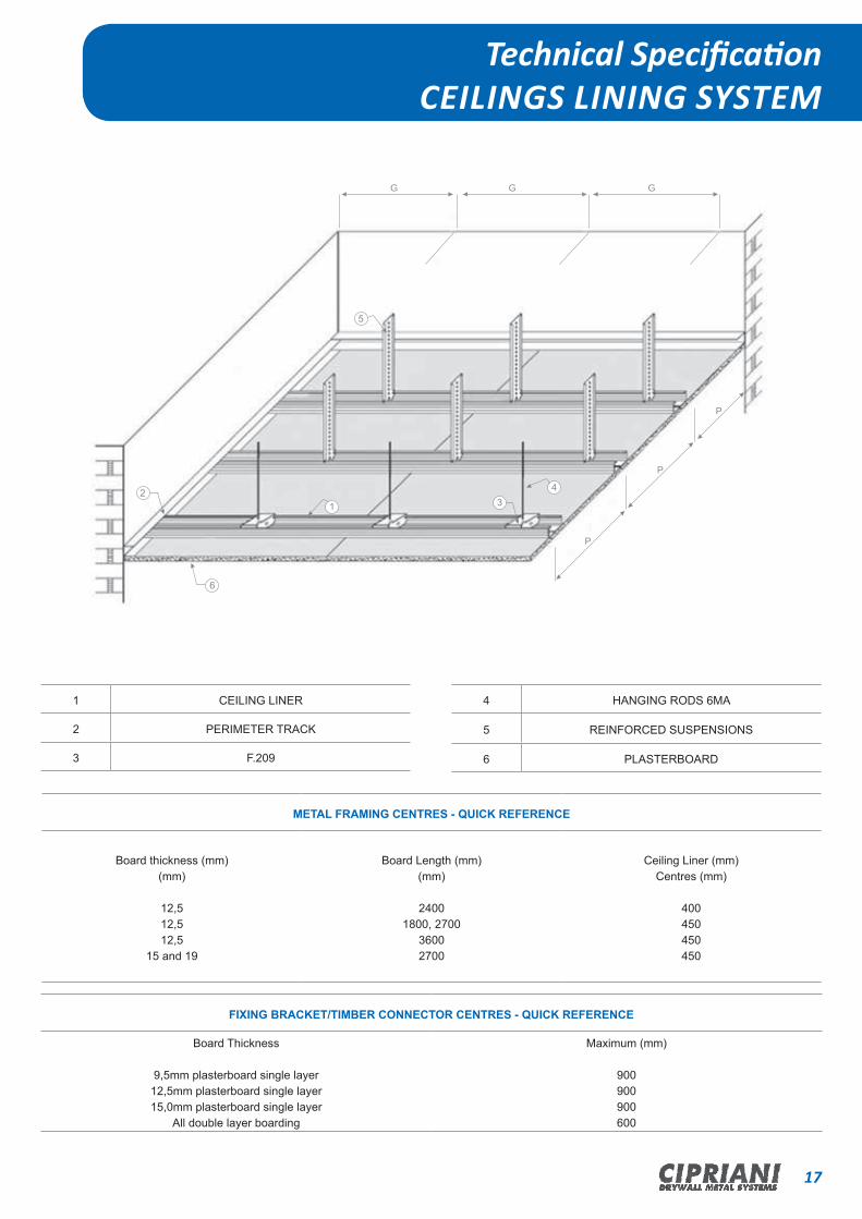
METAL FRAMING CENTRES - QUICK REFERENCE
Board thickness (mm)(mm)
12,512,512,5
15 and 19
Board Length (mm)(mm)
24001800, 2700
36002700
Ceiling Liner (mm)Centres (mm)
400450450450
FIXING BRACKET/TIMBER CONNECTOR CENTRES - QUICK REFERENCE
Board Thickness
9,5mm plasterboard single layer12,5mm plasterboard single layer15,0mm plasterboard single layer
All double layer boarding
Maximum (mm)
900900900600
1 CEILING LINER
2 PERIMETER TRACK
3 F.209
Technical SpecificationCEILINGS LINING SYSTEM
4 HANGING RODS 6MA
5 REINFORCED SUSPENSIONS
6 PLASTERBOARD
G G
P
P
2
6
431
G
5
P


L-SHAPED PROFILES OMEGA PROFILES
STAFF ANGLES EDGE BEADS
FOR ALL SYSTEMS

20 CIPRIANI DRYWALL METAL SYSTEMS
Staff angles - Edge BeadsL-Shaped Profiles - Omega Profiles Channels for omega
SECTION PROFILE CODE DIMENSIONS (mm) PACK SIZE
L 30 x 20L 30 x 30
L-Shaped profileThickness 0,60 mm
LW302006LW303006 30 20
30 500 50 no packs x 10 no lengths
L 30 x 40L 40 x 40L 50 x 40
L-Shaped profileThickness 0,60 mmThickness 0,70 mmThickness 0,60 mm
LW304006LW404007LW504006
40304050
250 25 no packs x 10 no lengths
L 40 x 50 Variable angleThickness 0,70 mm LW405007 50 40 250 50 no packs x
10 no lengths
OM 4215OM 4220OM 4270OM 4236
OmegaThickness 0,60 mm
OM421506OM422006OM422706OM423606
42
15202736
200 20 no packs x 10 no lengths
OM 4215OM 4220OM 4270OM 4236
OmegaThickness 1,00 mm
OM421510OM422010OM422710OM423610
42
15202736
200 20 no packs x 10 no lengths
UD 1628---
UD 2225UD 2830UD 3830
Channel for omegaThickness 0,60 mm
UD162806---
UD222506UD283006UD383006
16--- 222838
28--- 252730
360
300
45 no packs x 8 no lengths
25 no packs x 12 no lengths
Base SideDescription Number of pieces
SID
E
BASE
SID
E
BASE
SID
E
BASE
SIDE
42
1,0g f
SIDE
42
0,6g f
(Length 3.000 mm)
(Length 3.000 mm)
(Length 3.000 mm)

21CIPRIANI DRYWALL METAL SYSTEMS
Staff angles - Edge Beads
SECTION PROFILE CODE DIMENSIONS (mm) PACK SIZE
90° Staff angleThickness 0,50 mm LW303005 30 30 500 50 no packs x
10 no lengths
135° Staff angleThickness 0,50 mm LW31135G 30 30 500 50 no packs x
10 no lengths
Variable AnglePatented variable staff angle
Thickness 0,60 mmLW30AVBR 30 30 500 50 no packs x
10 no lengths
Edge beadThickness 0,50 mm LW153005 15 30 500 50 no packs x
10 no lengths
Base SideDescription Number of pieces
(Length 3.000 mm)Other lengths available
on demand
(Length 3.000 mm)Other lengths available
on demand
(Length 3.000 mm)
(Length 3.000 mm)


FLEX PROFILES

24 CIPRIANI DRYWALL METAL SYSTEMS
FLEX SPECIAL PROFILES
These special profiles allow the creation of curved partition walls,
ceilings, vaults and decorative coverings.
The range of CIPRIANI FLEX profiles can meet all your requirements
as the range includes:
• channels for walls
• profiles for ceilings
• staff angles
• edge beads
FLEX profiles, combined with standard profiles, allow the construction
of complex plasterboard structures with special shapes.
CIPRIANI PROFILATI manufactures these profiles to a high standard,
profiles are packaged for ease of handling and to make safety a priority.
STEEL
CIPRIANI profiles are made of carbon steel type DX51D hot-galvanized
using “sendzimir” process with a yield strength exceeding 280 N/sqmm
and defined by European Standards UNI EN 10327.
The profiles zinc coating varies from 100 g/sqm. to 275 g/sqm depending
on needs.
The surface of all profiles is also protected by chromic acid chemical
passivation.
For all profiles thicknesses, please refer to profiles individual specifications
contained in this catalogue. Profiles thicknesses tolerances are defined
by Standards UNI EN 10143.
CIPRIANI has an "In House" laboratory for material testing, this
guarantees to our customers that a high degree of quality, this will
ensure that safety will be achieved.
STORAGE SUGGESTIONS
As humidity and atmospheric agents in general may oxidize and cause
white rust formation on the profile surface of material, please take the
following precautions:
• Store profiles in covered and ventilated area;
• keep material away from corrosive agents such as combustion
outputs, chemical vapors and dust caused by manufacturing
• protect profiles with polyethylene covers which make sure that
Product Features
air is recirculated to avoid condensation;
• In case of outdoors storage (not recommended) put the packs at a
slight angle to allow any water infiltration to drain freely.
ACCESSORIES
The range of accessories suitable for CIPRIANI FLEX profiles is the same
those used for standard profiles.
For a detailed description, please refer to the accessories section in this
catalogue.
25CIPRIANI DRYWALL METAL SYSTEMS
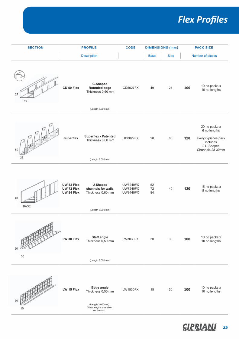
Flex Profiles
SECTION PROFILE CODE DIMENSIONS (mm) PACK SIZE
CD 50 FlexC-Shaped
Rounded edge Thickness 0,60 mm
CD5027FX 49 27 100 10 no packs x 10 no lengths
Superflex Superflex - Patented Thickness 0,60 mm UD8029FX 28 80 120
20 no packs x 6 no lengths
every 6-pieces pack includes
2 U-Shaped Channels 28-30mm
UW 52 FlexUW 72 FlexUW 94 Flex
U-Shaped channels for wallsThickness 0,60 mm
UW5240FXUW7240FXUW9440FX
527294
40 120 15 no packs x 8 no lengths
LW 30 Flex Staff angleThickness 0,50 mm LW3030FX 30 30 100 10 no packs x
10 no lengths
LW 15 Flex Edge angleThickness 0,50 mm LW1530FX 15 30 100 10 no packs x
10 no lengths
27
49
80
28
40
BASE
30
30
30
15
Base SideDescription Number of pieces
(Length 3.000 mm)
(Length 3.000 mm)
(Length 3.000 mm)
(Length 3.000 mm)
(Length 3.000mm)Other lengths available
on demand

26 CIPRIANI DRYWALL METAL SYSTEMS
Flex Profiles Applications: C-Shaped Profile - Superflex Patented - U-Shaped Channel - Staff Angle-edge bead
APPLICATIONS: creation of tunnels, vaults, ceilings, partitions and wall linings with curved configurations.
APPLICATIONS: Designed to carry out a variety of curved configurations,it offers a great deal of flexibility.
APPLICATIONS: The best solution for construction of curved partition walls of every shape and size
APPLICATIONS: The finishing and reinforcement of curved edges and corners with a great deal of flexibility.

CLP PROFILES FOR PRIMARY
STRUCTURES

28 CIPRIANI DRYWALL METAL SYSTEMS
Product Features
FEATURES
CIPRIANI CLP profiles for primary structures can be used for suspended
ceilings installation for both standard and concealed systems.
In case of in sight structure the French Standards DTU 58/1 contemplate
a camber up to 1/300th of span between CLP profiles (As an example:
with a span of 1000 mm the camber must be 3.33mm).
The maximum camber depends both on the span (meant as the distance
between supports or point of supports), and on the borne load (made of
the weight of the ceiling and of the support structure).
The load tables on the next page have been created to make design and
installations decision quicker and more precise.
Please note that if CIPRIANI CLP profiles are used as primary support
structure, a secondary structure connected by means of adjustable
supports, the maximum allowed camber is 1/300th, regardless of the kind
of false ceiling chosen.
For a correct assembly of the structure, please follow some easy directions
for use:
• CLP main profiles must be connected by means of stiffening profiles
(CD5027 or CD5015) so as to form a rigid structure (see table below);
• CLP profiles longitudinal joints should not be assembled lined up at
the same distance, but alternately. Bolts of the right size should be
used in all available fixing holes;
• Bolts should be assembled in wall squares as well, including
screw anchors in the walls;
• CLP profiles longitudinal Joints should be placed as close as possible
to support points;
• Longitudinal joints and wall squares must always be assembled in
pairs and never one by one.
DISTANCE BETWEEN STIFFENING PROFILESProfil Span betweenCLP
profiles (mm)Distance between stiffening
profiles (mm)CLP054 1250 - 3500 625 - 1750
CLP070 1750 - 4000 875 - 2000
CLP085 3000 - 4000 1500 - 2000
CLP120 3500 - 4500 1750 - 2250
CLP085 4100 - 5000 1400 - 1700
CLP120 4600 - 6500 1500 - 2000
1
1
2
2
3
3
4
4
5
5
6
6
7
7
8
8
A A
B B
C C
D D
E E
F F
Assieme struttura CLP
1 di 1
G.Carbonari 26/09/2012Disegnato Controllato Approvato Data
Revisione Foglio
2011-005-00030-A
CLASSE DI TOLLERANZA GENERALE (mm): Designazionesecondo UNI EN ISO 22768 - Scostamenti limite ammessiper campi di dimensioni nominali lineari - CLASSE FINE
L>=0.5L<=3± 0.05
L>30L<=120± 0.15
L>3L<=6± 0.05
L>6L<=30± 0.1
L>120L<=400± 0.2
L>1000L<=2000± 0.5
L>400L<=1000± 0.3
L>2000L<=4000± 1.0
Scala
--
Cipriani Profilati s.r.l. - Ogni diritto sui contenuti del presente disegno è riservato ai sensi dellanormativa vigente. La sua riproduzione, la pubblicazione e la distribuzione, totale o parziale,(tra cui, a titolo esemplificativo e non esaustivo, i testi, le immagini, i disegni grafici) sonoespressamente vietate in assenza di autorizzazione scritta da parte dell'azienda sopra citata.
Codice disegnoCIPRIANI PROFILATI s.r.l. - Via Pineta,31 - 38068 Rovereto (TN) ItalyP.Iva 01173470228 - Tel. +39 0464 421412 - Fax. +39 0464 431330
E-mail: [email protected] - Web: www.ciprianiprofilati.it
Toll. Angolare± 0.1°
LISTA PARTINoteMaterialePeso (Kg)DescrizioneN. DisegnoQtàPos
3226,97Assieme struttura CLP2011-005-00030-A11
B
A
1. Ø 6 X 15 mm NUT AND BOLT2. C-SHAPED PROFILE FOR FALSE
CEILINGS
3. LONGITUDINAL JOINT4. WALL SQUARE5. “T” MAIN RUNNER
6. STIFFENING PROFILE7. CLP PROFILE8. F.218
9. F.22410. F.22011. F.219
1. 4.2.
3.
5.
9.
8.
7.
6.
11.
10.

29CIPRIANI DRYWALL METAL SYSTEMS
CLP Profiles for Primary Structures
SECTION PROFILE CODE DIMENSIONS (mm) PACK SIZE
CLP 120
Profile CLP
Thickness 1,20 mmThickness 1,00 mm
CLP12012CLP12010 40 120 6.500
5.500 72 18 no packs x 4 no lengths
CLP 08506CLP 08508CLP 08510
Profile CLP
Thickness 0,60 mmThickness 0,80 mmThickness 1,00 mm
CLP08506CLP08508CLP08510
40 855.0005.0005.500
108 27 no packs x 4 no lengths
CLP 07008CLP 07006
Profile CLP
Thickness 0,80 mm Thickness 0,60 mm
CLP07008CLP07006 40 70 5.000 144 36 no packs x
4 no lengths
CLP 05406CLP 05405
Profile CLP
Thickness 0,60 mm Thickness 0,50 mm
CLP05406CLP05405 40 54 5.000 180 45 no packs x
4 no lengths
ACCESSORY: code description page number reference
F.210F.211F.212F.213
Wall Square 36
F.218F.221 Click-on Support 36
F.219 Click-on Support 36
ACCESSORY: code description page number reference
F.214F.215F.216F.217
Longitudinal Joint 36
F.220 Click-on Support 36
F.224 Click-on support 36
Base LengthDescription Number of piecesSide
Product Features
30 CIPRIANI DRYWALL METAL SYSTEMS
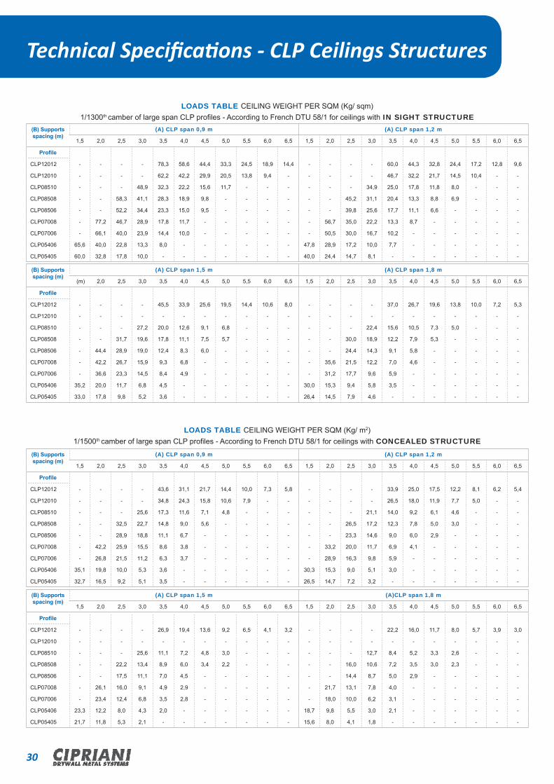
Technical Specifications - CLP Ceilings Structures
LOADS TABLE CEILING WEIGHT PER SQM (Kg/ sqm)1/1300th camber of large span CLP profiles - According to French DTU 58/1 for ceilings with IN SIGHT STRUCTURE
(B) Supports spacing (m)
(A) CLP span 0,9 m (A) CLP span 1,2 m
1,5 2,0 2,5 3,0 3,5 4,0 4,5 5,0 5,5 6,0 6,5 1,5 2,0 2,5 3,0 3,5 4,0 4,5 5,0 5,5 6,0 6,5
Profile
CLP12012 - - - - 78,3 58,6 44,4 33,3 24,5 18,9 14,4 - - - - 60,0 44,3 32,8 24,4 17,2 12,8 9,6
CLP12010 - - - - 62,2 42,2 29,9 20,5 13,8 9,4 - - - - - 46,7 32,2 21,7 14,5 10,4 - -
CLP08510 - - - 48,9 32,3 22,2 15,6 11,7 - - - - - - 34,9 25,0 17,8 11,8 8,0 - - -
CLP08508 - - 58,3 41,1 28,3 18,9 9,8 - - - - - - 45,2 31,1 20,4 13,3 8,8 6,9 - - -
CLP08506 - - 52,2 34,4 23,3 15,0 9,5 - - - - - - 39,8 25,6 17,7 11,1 6,6 - - - -
CLP07008 - 77,2 46,7 28,9 17,8 11,7 - - - - - - 56,7 35,0 22,2 13,3 8,7 - - - - -
CLP07006 - 66,1 40,0 23,9 14,4 10,0 - - - - - - 50,5 30,0 16,7 10,2 - - - - - -
CLP05406 65,6 40,0 22,8 13,3 8,0 - - - - - - 47,8 28,9 17,2 10,0 7,7 - - - - - -
CLP05405 60,0 32,8 17,8 10,0 - - - - - - - 40,0 24,4 14,7 8,1 - - - - - - -
(B) Supports spacing (m)
(A) CLP span 1,5 m (A) CLP span 1,8 m
(m) 2,0 2,5 3,0 3,5 4,0 4,5 5,0 5,5 6,0 6,5 1,5 2,0 2,5 3,0 3,5 4,0 4,5 5,0 5,5 6,0 6,5
Profile
CLP12012 - - - - 45,5 33,9 25,6 19,5 14,4 10,6 8,0 - - - - 37,0 26,7 19,6 13,8 10,0 7,2 5,3
CLP12010 - - - - - - - - - - - - - - - - - - - - - -
CLP08510 - - - 27,2 20,0 12,6 9,1 6,8 - - - - - - 22,4 15,6 10,5 7,3 5,0 - - -
CLP08508 - - 31,7 19,6 17,8 11,1 7,5 5,7 - - - - - 30,0 18,9 12,2 7,9 5,3 - - - -
CLP08506 - 44,4 28,9 19,0 12,4 8,3 6,0 - - - - - - 24,4 14,3 9,1 5,8 - - - - -
CLP07008 - 42,2 26,7 15,9 9,3 6,8 - - - - - - 35,6 21,5 12,2 7,0 4,6 - - - - -
CLP07006 - 36,6 23,3 14,5 8,4 4,9 - - - - - - 31,2 17,7 9,6 5,9 - - - - - -
CLP05406 35,2 20,0 11,7 6,8 4,5 - - - - - - 30,0 15,3 9,4 5,8 3,5 - - - - - -
CLP05405 33,0 17,8 9,8 5,2 3,6 - - - - - - 26,4 14,5 7,9 4,6 - - - - - - -
LOADS TABLE CEILING WEIGHT PER SQM (Kg/ m2)1/1500th camber of large span CLP profiles - According to French DTU 58/1 for ceilings with CONCEALED STRUCTURE
(B) Supports spacing (m)
(A) CLP span 0,9 m (A) CLP span 1,2 m
1,5 2,0 2,5 3,0 3,5 4,0 4,5 5,0 5,5 6,0 6,5 1,5 2,0 2,5 3,0 3,5 4,0 4,5 5,0 5,5 6,0 6,5
Profile
CLP12012 - - - - 43,6 31,1 21,7 14,4 10,0 7,3 5,8 - - - - 33,9 25,0 17,5 12,2 8,1 6,2 5,4
CLP12010 - - - - 34,8 24,3 15,8 10,6 7,9 - - - - - - 26,5 18,0 11,9 7,7 5,0 - -
CLP08510 - - - 25,6 17,3 11,6 7,1 4,8 - - - - - - 21,1 14,0 9,2 6,1 4,6 - - -
CLP08508 - - 32,5 22,7 14,8 9,0 5,6 - - - - - - 26,5 17,2 12,3 7,8 5,0 3,0 - - -
CLP08506 - - 28,9 18,8 11,1 6,7 - - - - - - - 23,3 14,6 9,0 6,0 2,9 - - - -
CLP07008 - 42,2 25,9 15,5 8,6 3,8 - - - - - - 33,2 20,0 11,7 6,9 4,1 - - - - -
CLP07006 - 26,8 21,5 11,2 6,3 3,7 - - - - - - 28,9 16,3 9,8 5,9 - - - - - -
CLP05406 35,1 19,8 10,0 5,3 3,6 - - - - - - 30,3 15,3 9,0 5,1 3,0 - - - - - -
CLP05405 32,7 16,5 9,2 5,1 3,5 - - - - - - 26,5 14,7 7,2 3,2 - - - - - - -
(B) Supports spacing (m)
(A) CLP span 1,5 m (A)CLP span 1,8 m
1,5 2,0 2,5 3,0 3,5 4,0 4,5 5,0 5,5 6,0 6,5 1,5 2,0 2,5 3,0 3,5 4,0 4,5 5,0 5,5 6,0 6,5
Profile
CLP12012 - - - - 26,9 19,4 13,6 9,2 6,5 4,1 3,2 - - - - 22,2 16,0 11,7 8,0 5,7 3,9 3,0
CLP12010 - - - - - - - - - - - - - - - - - - - - - -
CLP08510 - - - 25,6 11,1 7,2 4,8 3,0 - - - - - - 12,7 8,4 5,2 3,3 2,6 - - -
CLP08508 - - 22,2 13,4 8,9 6,0 3,4 2,2 - - - - - 16,0 10,6 7,2 3,5 3,0 2,3 - - -
CLP08506 - - 17,5 11,1 7,0 4,5 - - - - - - - 14,4 8,7 5,0 2,9 - - - - -
CLP07008 - 26,1 16,0 9,1 4,9 2,9 - - - - - - 21,7 13,1 7,8 4,0 - - - - - -
CLP07006 - 23,4 12,4 6,8 3,5 2,8 - - - - - - 18,0 10,0 6,2 3,1 - - - - - -
CLP05406 23,3 12,2 8,0 4,3 2,0 - - - - - - 18,7 9,8 5,5 3,0 2,1 - - - - - -
CLP05405 21,7 11,8 5,3 2,1 - - - - - - - 15,6 8,0 4,1 1,8 - - - - - - -

ACCESSORIES Technical Specifications - CLP Ceilings Structures
32 CIPRIANI DRYWALL METAL SYSTEMS
Product Features
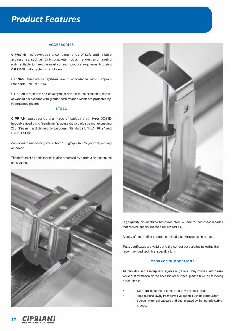
ACCESSORIES
CIPRIANI has developed a complete range of safe and reliable accessories, such as joints, brackets, hooks, hangers and hanging rods, suitable to meet the most common practical requirements during CIPRIANI metal systems installation.
CIPRIANI Suspension Systems are in accordance with European Standards UNI EN 13964.
CIPRIANI ‘s research and development has led to the creation of someadvanced accessories with greater performance which are protected byinternational patents!
STEEL
CIPRIANI accessories are made of carbon steel type DX51D hot-galvanized using “sendzimir” process with a yield strength exceeding 280 N/sq mm and defined by European Standards UNI EN 10327 and UNI EN 14195.
Accessories zinc coating varies from 100 g/sqm. to 275 g/sqm depending on needs.
The surface of all accessories is also protected by chromic acid chemical passivation.
High quality nickel-plated tempered steel is used for some accessories that require special mechanical properties.
A copy of the traction strength certificate is available upon request.
Tests certificates are valid using the correct accessories following therecommended technical specifications
STORAGE SUGGESTIONS
As humidity and atmospheric agents in general may oxidize and cause white rust formation on the accessories surface, please take the following precautions:
• Store accessories in covered and ventilated area;• keep material away from corrosive agents such as combustion outputs, chemical vapours and dust created by the manufacturing process.

33CIPRIANI DRYWALL METAL SYSTEMS
Accessories Systems
ACCESSORY DESCRIPTION CODE Number of pieces / BOX
WEIGHTKg/package
systems
EXTENSION
Length 300 mmLength 500 mm
To extend C-Shaped Profile CD48
F.222F.223
400400 2,41
LONGITUDINAL JOINT
For C-Shaped Profile for ceilings 45x18mm
F.201 100 3,93
LONGITUDINAL JOINT
For C-Shaped Profile for ceilings 48x18mm
F.202 100 2,21
PIVOT SPACER HOOKFor C-Shaped Profile for
ceilings C 45x18mm and C 48x18mm
6MA threaded hole and 6mm through holes for
HANGING RODS
F.209
100 6,13
REINFORCED SUSPENSIONS
80 mm Length180 mm Length240 mm Length320 mm Length400 mm Length480 mm Length
4mm holes for C-Shaped Profile for ceilings C 45x18mm
and C48x18mm
F.203F.204F.205F.206F.207F.208
10010050505050
2,214,983,324,305,576,67
Product Features

34 CIPRIANI DRYWALL METAL SYSTEMS
Accessories - Brackets - Squared
Accessories - Hanging Rods
Accessories for CD5027
ACCESSORY DESCRIPTION CODE Number of pieces / BOX
WEIGHTKg/package systems
HOOK WITH SPRINGFor CD5015 and CD5027 Profiles Rounded Edge
C.002 100 3,62
SPACER HOOK6mm Through Hole
For CD5015 and CD5027 Profiles Rounded Edge
C.091 100 3,05
SPACER HOOK6mm Through Hole
For CD5015 and CD5027 Profiles Rounded Edge
C.035 100 3,05
ORTHOGONAL UNION HOOK
For CD5027 ProfileRounded Edge
Patented
C.007 100 1,46
ORTHOGONAL CLICK-ON SPACER
HOOK For CD5027 Profile
Rounded Edge
Patented
C.113 50 2,30
SPACER HOOK20 mm30 mm
for CD5015 and CD5027 ProfilesRounded Edge
C.101C.103 100 3,82
4,52
LONGITUDINAL JOINT
For CD5015 ProfileC.008 100 3,12
LONGITUDINAL JOINT
For CD5027 ProfileC.009 100 4,62
27
35CIPRIANI DRYWALL METAL SYSTEMS
Accessories - Brackets - Squared
ADJUSTABLE BRACKET
50x40 mm50x60 mm
For C50 Profiles
C.131C.130 100 2,75
3,34
ADJUSTABLE BRACKET
50x80 mm50x120 mm
For C50 Profiles
C.129C.126 100 4,13
5,70
AC
CE
SS
OR
Y
DE
SC
RIP
TIO
N
CO
DE
Num
ber
of
piec
es /
BO
X
WE
IGH
T
Kg/
pack
age
SQUARE70x35 mm
C.010 100 2,96
SQUARE120x35 mm
C.069 100 4,16
AC
CE
SS
OR
Y
DE
SC
RIP
TIO
N
CO
DE
Num
ber
of
piec
es /
BO
X
WE
IGH
T
Kg/
pack
age
Accessories - Hanging Rods
ADJUSTABLE DOUBLE SPRING
FOR HANGING RODS
C.039 100 1,65
4 mm HANGING ROD
125 mm Length250 mm Length375 mm Length500 mm Length750 mm Length1000 mm Length1500 mm Length2000 mm Length2500 mm Length3000 mm Length4000 mm Length
C.040.IC.017.IC.041.IC.018.IC.042.IC.019.IC.043.IC.044.IC.140.IC.138.IC.139.I
100
50
1,602,804,105,307,0010,4015,3020,4012,8015,3020,40
4 mm HANGING ROD
125 mm Length250 mm Length375 mm Length500 mm Length750 mm Length
1000 mm Length1500 mm Length2000 mm Length2500 mm Length3000 mm Length4000 mm Length
C.040.O / 90C.017.O / 90C.041.O / 90C.018.O / 90C.042.O / 90C.019.O / 90C.043.O / 90C.044.O / 90C.140.O / 90C.138.O / 90C.139.O / 90
100
50
1,602,804,105,307,0010,4015,3020,4012,8015,3020,40
4 mm HANGING ROD
125 mm Length250 mm Length375 mm Length500 mm Length750 mm Length
1000 mm Length1500 mm Length2000 mm Length2500 mm Length3000 mm Length4000 mm Length
C.040.J / VC.017.J / VC.041.J / VC.018.J / VC.042.J / VC.019.J / VC.043.J / VC.044.J / VC.140.J / VC.138.J / VC.139.J / V
100
50
1,602,804,105,307,0010,4015,3020,4012,8015,3020,40
TYPE "I" TYPE "J"
TYPE "V"
TYPE "90"
TYPE "0"
syst
ems
syst
ems
AC
CE
SS
OR
Y
DE
SC
RIP
TIO
N
CO
DE
Num
ber
of
piec
es /
BO
X
WE
IGH
T
Kg/
pack
age
syst
ems
AC
CE
SS
OR
Y
DE
SC
RIP
TIO
N
CO
DE
Num
ber
of
piec
es /
BO
X
WE
IGH
T
Kg/
pack
age
syst
ems

36 CIPRIANI DRYWALL METAL SYSTEMS
WALL SQUAREFor Profiles:CLP12012 CLP12010
F.210 50 8,10
LONGITUDINAL JOINT
For Profiles:CLP12012 CLP12010
F.214 50 14,10
CLICK-ON SUPPORT For C-Shaped profiles for ceilings CD45 and CD48
For C-Shaped profile CD50276A
Pressed Edge In 2 sections and suitable
for use with all CLP profiles
F.218 100 5,48
BOTTOM SUPPORTFor Ø 6 mm Threaded Bar Suitable for use with all CLP profiles
F.220 100 4,95
PROFILE SUPPORTFor T Profiles for
suspended ceilings. In 2 sections and suitable for use with all CLP profiles
F.224 100 5,87
WALL SQUAREFor Profiles:
CLP08510 - CLP08508 - CLP08506
CLP07008 - CLP07006CLP05406 - CLP05405
F.211
F.212
F.213
50
5,95
4,70
2,64
LONGITUDINAL JOINT
For Profiles:CLP08510 - CLP08508
- CLP08506CLP07008 - CLP07006CLP05406 - CLP05405
F.215
F.216
F.217
50
11,27
6,70
4,13
CLICK-ON SUPPORT For C-Shaped profiles for ceilings CD45 and CD48
For C-Shaped profile CD50276A
Rounded Edge In 2 sections and suitable
for use with all CLP profiles
F.221 100 5,48
TOP SUPPORTFor Ø 8 mm Threaded Bar In 2 sections and
suitable for use with all CLP profiles
F.219 100 7,63
AC
CE
SS
OR
Y
DE
SC
RIP
TIO
N
CO
DE
Num
ber
of
piec
es /
BO
X
WE
IGH
T
Kg/
pack
age
syst
ems
AC
CE
SS
OR
Y
DE
SC
RIP
TIO
N
CO
DE
Num
ber
of
piec
es /
BO
X
WE
IGH
T
Kg/
pack
age
syst
ems
Accessories - CLP Primary structures

METAL GRID SYSTEM FOR SUSPENDED CEILINGS
38 CIPRIANI DRYWALL METAL SYSTEMS
Product Features
INNOVATION IN SUSPENDED CEILINGS
TeebuildTM AND TeetaniumTM
CIPRIANI PROFILATI, a family-run group, believes in research and
development to ensure a continuous improvement of its products,
services and offers.
The passion for what we do is a key component in how we develop and
manufacture our products. The development of new building systems
is the result of constant study and the ability to innovate.
While developing each of our new products ( profiles, accessories, ceiling
grid.. ), we look to consider ease of instalation and customer satisfaction.
Thanks to our business philosophy and our long-time experience in the
field of ceiling grid, we have created the new metal grid systems
TeebuildTM and TeetaniumTM.
These new grid systems, have a classic “click” on installation which
confirms the perfect connection between various profiles,they are
protected by seven international patents.
The new clip junction has been designed and made of stainless steel, to
ensure maximum strength and greater safety when profiles are
assembled, and at the same time offer flexibility of being fully demountable
Demounting is quick and easy, just apply pressure to the button on
the centre of the clip. The ‘click’ produced by the tab confirms that
the clip has been released and that profiles are released, no tools are
required,it is so easy!
Thanks to a new type of coupling obtained directly on the clip, in the
new systems TeebuildTM and TeetaniumTM, the application of the clip to
the profile has been made even more secure.
An innovative and exclusive anti-torsion lock system, created on
TeebuildTM and TeetaniumTM profiles vertical side, guarantees extreme
rigidity and great stability under load.
For the production of the TeetaniumTM structure, we patented the use of
a brand new material in our field, it is strong with unique features and
unrivaled mechanical properties.
Both TeebuildTM and TeetaniumTM grid structures are produced ac-
cording to the EN 13964 European regulation and in full compliance
with the highest quality standards. They combine practicality of use
and great flexibility in every situation. To be brief: maximum output with
minimum effort!
The new TeetaniumTM grid system is available in a large range of sizes 15
mm, 24 mm and 35 mm. In addition, the TeebuildTM system is available in
42 mm uncapped for the installation of plasterboard. Each size can be
chosen in the following dimensions: 600 mm, 610 mm, 625 mm and 675 mm.
39CIPRIANI DRYWALL METAL SYSTEMS
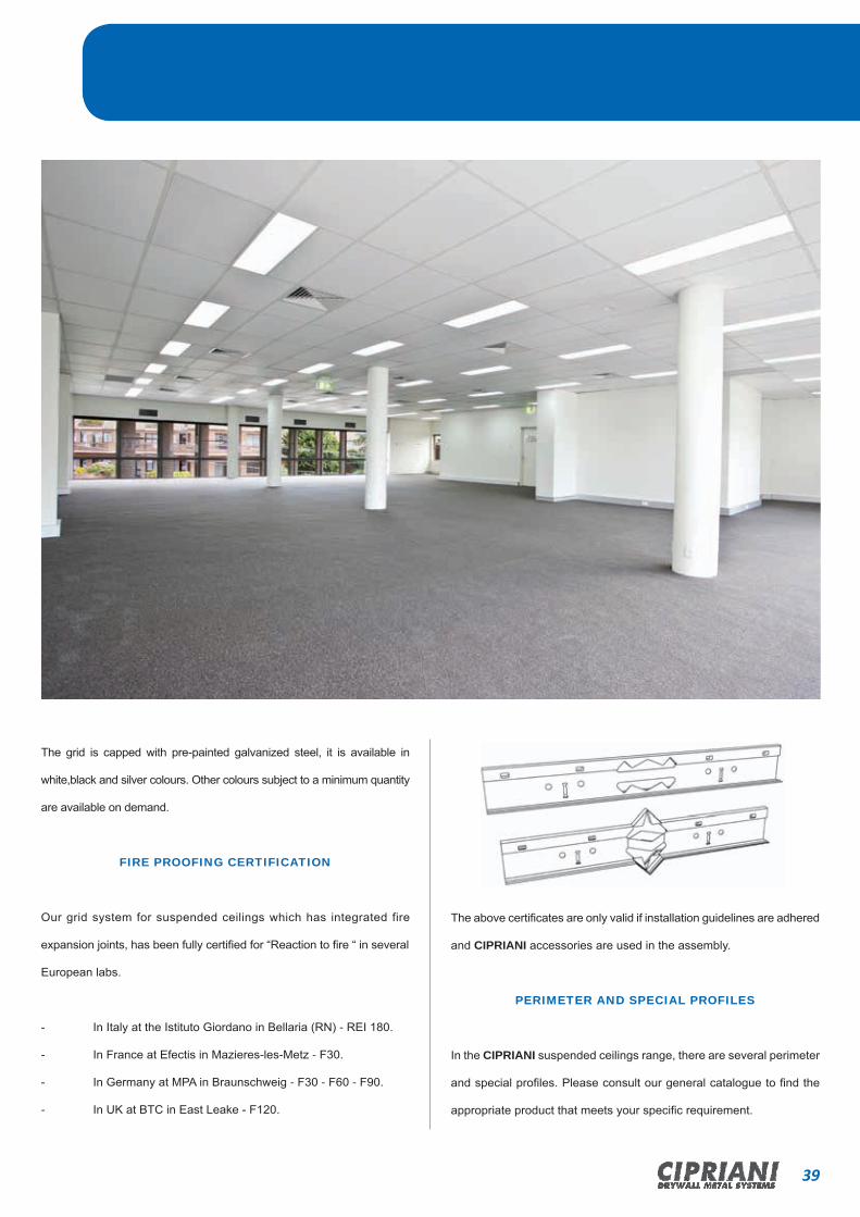
The grid is capped with pre-painted galvanized steel, it is available in
white,black and silver colours. Other colours subject to a minimum quantity
are available on demand.
FIRE PROOFING CERTIFICATION
Our grid system for suspended ceilings which has integrated fire
expansion joints, has been fully certified for “Reaction to fire “ in several
European labs.
- In Italy at the Istituto Giordano in Bellaria (RN) - REI 180.
- In France at Efectis in Mazieres-les-Metz - F30.
- In Germany at MPA in Braunschweig - F30 - F60 - F90.
- In UK at BTC in East Leake - F120.
The above certificates are only valid if installation guidelines are adhered
and CIPRIANI accessories are used in the assembly.
PERIMETER AND SPECIAL PROFILES
In the CIPRIANI suspended ceilings range, there are several perimeter
and special profiles. Please consult our general catalogue to find the
appropriate product that meets your specific requirement.
Product Features

40 CIPRIANI DRYWALL METAL SYSTEMS
HD24 System TeetaniumTM
Exposed 24mm “T” GridClick-on Overlapping Assembly
C
HANGER PERIMETER PROFILE
MAIN RUNNER
600 CROSS TEE1200 CROSS TEE
BA
ACCESSORIES page number reference 63
C.039 - HANGING RODS V WIRE LW302006
MAIN RUNNER
1200 CROSS TEE
600 CROSS TEE
X
YY38
24
38
24
24
38
X
X X
X
L
X X
X
L
L
Structure according to EN 13964.
Fire Proofing Certification - upon request.
Standard colours: White – Black – Silver (other colours available on demand).
Corrosion resistance according to-Standards UNI EN 13964 B class.Extra corrosion resistence according to UNI EN13964 C class (only on demand).
For profiles with different lengths, make a specific request to CIPRIANI PROFILATI.
The load per square meter should be uniformly distributed (not granted additional load points). The arrow of flexion was calculated in accordan-ce with the class 1 (L/500) of EN 13964, providing that the installation of the substructure takes place as shown in the drawings.
Concentrated loads or additional weights such as lights, smoke detectors, air ducts, suspended signs, etc..are not allowed.
The maximum loads per m2 shown in the table include panels’ weight and any additional weight such as mineral wool or glass fiber to improve the acoustic and fire resistance features.
41CIPRIANI DRYWALL METAL SYSTEMS
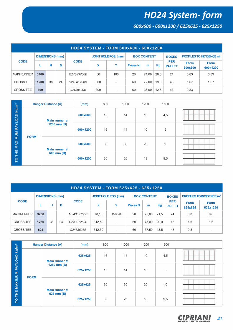
HD24 System- form600x600 - 600x1200 / 625x625 - 625x1250
HD24 SYSTEM - FORM 600x600 - 600x1200
CODEDIMENSIONS (mm)
CODEJOINT HOLE POS. (mm) BOX CONTENT BOXES
PER PALLET
PROFILES TO INCIDENCE m2
L H B X Y Pieces N. m KgForm
600x600Form
600x1200
MAIN RUNNER 3700
38 24
M24383700B 50 100 20 74,00 20,5 24 0,83 0,83
CROSS TEE 1200 C24381200B 300 - 60 72,00 19,0 48 1,67 1,67
CROSS TEE 600 C2438600B 300 - 60 36,00 12,5 48 0,83 -
HD24 SYSTEM - FORM 625x625 - 625x1250
CODEDIMENSIONS (mm)
CODEJOINT HOLE POS. (mm) BOX CONTENT BOXES
PER PALLET
PROFILES TO INCIDENCE m2
L H B X Y Pieces N. m KgForm
625x625Form
625x1250
MAIN RUNNER 3750
38 24
M24383750B 78,13 156,20 20 75,00 21,5 24 0,8 0,8
CROSS TEE 1250 C24381250B 312,50 - 60 75,00 20,0 48 1,6 1,6
CROSS TEE 625 C2438625B 312,50 - 60 37,50 13,5 48 0,8 -
TO T
HE
MA
XIM
UM
PAY
LOA
D k
g/m
2 Hanger Distance (A) (mm) 800 1000 1200 1500
FORM
Main runner at1200 mm (B)
600x600 16 14 10 4,5
600x1200 16 14 10 5
Main runner at600 mm (B)
600x600 30 30 20 10
600x1200 30 26 18 9,5
TO T
HE
MA
XIM
UM
PAY
LOA
D k
g/m
2 Hanger Distance (A) (mm) 800 1000 1200 1500
FORM
Main runner at1250 mm (B)
625x625 16 14 10 4,5
625x1250 16 14 10 5
Main runner at625 mm (B)
625x625 30 30 20 10
625x1250 30 26 18 9,5

42 CIPRIANI DRYWALL METAL SYSTEMS
HD24 SYSTEM - FORM 610x610 - 610x1220
DIMENSIONS (mm)CODE
JOINT HOLE POS. (mm) BOX CONTENT BOXES PER
PALLET
PROFILES TO INCIDENCE m2
L H B X Y Pieces N. m KgForm
610x610Form
610x1220
MAIN RUNNER 3657,6
38 24
M24383658B 76,20 152,40 20 73,15 19,5 24 0,82 0,82
CROSS TEE 1219,2 C24381220B 304,80 - 60 73,15 19,5 48 1,64 1,64
CROSS TEE 609,6 C2438610B 304,80 - 60 36,58 13,0 48 0,82 -
HD24 System - form610x610 - 610x1220 / 675x675 - 675x1350
TO T
HE
MA
XIM
UM
PAY
LOA
D k
g/m
2 Hanger Distance (A) (mm) 800 1000 1200 1500
FORM
Main runner at1220 mm (B)
610x610 16 14 10 4,5
610x1220 16 14 10 5
Main runner at610 mm (B)
610x610 30 30 20 10
610x1220 30 26 18 9,5
TO T
HE
MA
XIM
UM
PAY
LOA
D k
g/m
2 Hanger Distance (A) (mm) 1000 1350 1400 1600
FORM
Main runner at1350mm (B) 675x675 13 13 10 -
Main runner at675 mm (B) 675x675 22 18 15 8
HD24 SYSTEM - FORM 675x675 - 675x1350
DIMENSIONS (mm)CODE
JOINT HOLE POS. (mm) BOX CONTENT BOXES PER
PALLET
PROFILES INCIDENCE m2
L H B X Y Pieces N. m KgForm
675x675Form
675x1350
MAIN RUNNER 3712,5
38 24
M24383713B 84,38 168,75 20 74,25 21,0 24 1,48 0,74
CROSS TEE 1350 C24381350B 337,5 - 60 81 24,0 48 - 1,48
CROSS TEE 675 C2438675B 337,5 - 60 40,5 14,0 48 1,48 0,74
43CIPRIANI DRYWALL METAL SYSTEMS
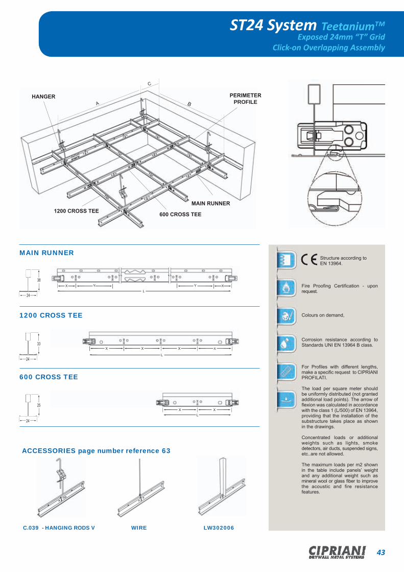
ST24 System TeetaniumTM
Exposed 24mm “T” GridClick-on Overlapping Assembly
C
HANGER PERIMETER PROFILE
MAIN RUNNER
600 CROSS TEE1200 CROSS TEE
BA
ACCESSORIES page number reference 63
C.039 - HANGING RODS V WIRE LW302006
MAIN RUNNER
1200 CROSS TEE
600 CROSS TEE
YYX X
L
38
24
24
25
XX X
L
X X
X
L
33
24
Structure according to EN 13964.
Fire Proofing Certification - upon request.
Colours on demand,
Corrosion resistance according to Standards UNI EN 13964 B class.
For Profiles with different lengths, make a specific request to CIPRIANI PROFILATI.
The load per square meter should be uniformly distributed (not granted additional load points). The arrow of flexion was calculated in accordance with the class 1 (L/500) of EN 13964, providing that the installation of the substructure takes place as shown in the drawings. Concentrated loads or additional weights such as lights, smoke detectors, air ducts, suspended signs, etc..are not allowed.
The maximum loads per m2 shown in the table include panels’ weight and any additional weight such as mineral wool or glass fiber to improve the acoustic and fire resistance features.

44 CIPRIANI DRYWALL METAL SYSTEMS
ST24 SYSTEM - FORM 600x600 - 600x1200
DIMENSIONS (mm)CODE
JOINT HOLE POS. (mm) BOX CONTENT BOXES PER
PALLET
PROFILES TO INCIDENCE m2
L H B X Y Pieces N. m KgForm
600x600Form
600x1200
MAIN RUNNER 3700 38
24
M24383700B 50 100 20 74,00 20,5 24 0,83 0,83
CROSS TEE 1200 33 C24331200B 300 - 60 72,00 17,0 48 1,67 1,67
CROSS TEE 600 25 C2425600B 300 - 60 36,00 7,5 48 0,83 -
ST24 SYSTEM - FORM 625x625 - 625x1250
DIMENSIONS (mm)CODE
JOINT HOLE POS. (mm) BOX CONTENT BOXES PER
PALLET
PROFILES TO INCIDENCE m2
L H B X Y Pieces N. m KgForm
625x625Form
625x1250
MAIN RUNNER 3750 38
24
M24383750B 78,13 156,20 20 75,00 21,5 24 0,8 0,8
CROSS TEE 1250 33 C24331250B 312,50 - 60 75,00 18,0 48 1,6 1,6
CROSS TEE 625 25 C2425625B 312,50 - 60 37,50 8,5 48 0,8 -
ST24 System - form600x600 - 600x1200 / 625x625 - 625x1250
TO T
HE
MA
XIM
UM
PAY
LOA
D k
g/m
2 Hanger Distance (A) (mm) 800 1000 1200 1500
FORM
Main runner at1200 mm (B)
600x600 12,7 10,5 7,5 -
600x1200 14 11,5 8 -
Main runner at600 mm (B)
600x600 30 30 20 10
600x1200 30 26 18 9,5
TO T
HE
MA
XIM
UM
PAY
LOA
D k
g/m
2 Hanger Distance (A) (mm) 800 1000 1200 1500
FORM
Main runner at1250 mm (B)
625x625 12,7 10,5 7,5 -
625x1250 14 11,5 8 -
Main runner at625 mm (B)
625x625 30 30 20 10
625x1250 30 26 18 9,5

45CIPRIANI DRYWALL METAL SYSTEMS
ST24 SYSTEM - FORM 610x610 – 610x1220
DIMENSIONS (mm)CODE
JOINT HOLE POS. (mm) BOX CONTENT BOXES PER
PALLET
PROFILES TO INCIDENCE m2
L H B X Y Pieces N. m KgForm
610x610Form
610x1220
MAIN RUNNER 3657,6 38
24
M24383658B 76,20 152,40 20 73,15 19,5 24 0,82 0,82
CROSS TEE 1219,2 33 C24331220B 304,80 - 60 73,15 17,5 48 1,64 1,64
CROSS TEE 609,6 25 C2425610B 304,80 - 60 36,58 8,0 48 0,82 -
ST24 System - form610x610 - 610x1220 / 675x675 - 675x1350
ST24 SYSTEM - FORM 675x675 – 675x1350
DIMENSIONS (mm)CODE
JOINT HOLE POS. (mm) BOX CONTENT BOXES PER
PALLET
PROFILES TO INCIDENCE m2
L H B X Y Pieces N. m KgForm
675x675Form
675x1350
MAIN RUNNER 3712,5 38
24
M24383713B 84,38 168,75 20 74,25 21,0 24 1,48 0,74
CROSS TEE 1350 33 C24331350B 337,5 - 60 81 20,0 48 - 1,48
CROSS TEE 675 25 C2425675B 337,5 - 60 40,5 10,0 48 1,48 0,74
TO T
HE
MA
XIM
UM
PAY
LOA
D k
g/m
2 Hanger Distance (A) (mm) 800 1000 1200 1500
FORM
Main runner at1220 mm (B)
610x610 12,7 10,5 7,5 -
610x1220 14 11,5 30 26
Main runner at610 mm (B)
610x610 30 30 20 10
610x1220 30 26 18 9,5
TO T
HE
MA
XIM
UM
PAY
LOA
D k
g/m
2 Hanger Distance (A) (mm) 1000 1350 1400 1600 1600
FORM
Main runner at1350 mm (B) 675x675 9 9 7 - -
Main runner at675 mm (B) 675x675 22 18 15 8 8

46 CIPRIANI DRYWALL METAL SYSTEMS
C
HANGER PERIMETER PROFILE
MAIN RUNNER
600 CROSS TEE1200 CROSS TEE
BA
MAIN RUNNER
1200 CROSS TEE
600 CROSS TEE
YYX X
L
38
24
24
25
XX X
L
X X
X
L
33
24
CR24 Corrosion Protected System TeetaniumTM
According to EN 13964 C Class - Exposed 24mm “T” GridClick-on Overlapping assembly
ACCESSORIES page number reference 63
CORNER
Structure according to EN 13964.
Corrosion resistance according to Standards EN 13964 C class.
Colours on demand.
For Profiles with different lengths make a specific request to CIPRIANI PROFILATI.
The load per square meter should be uniformly distributed (not granted additional load points). The arrow of flexion was calculated in accordance with the class 1 (L/500) of EN 13964, providing that the installation of the substructure takes place as shown in the drawings.
Concentrated loads or additional weights such as lights, smoke detectors, air ducts, suspended signs, etc..are not allowed.
The maximum loads per m2 shown in the table include panels’ weight and any additional weight such as mineral wool or glass fiber to improve the acoustic and fire resistance features.
47CIPRIANI DRYWALL METAL SYSTEMS
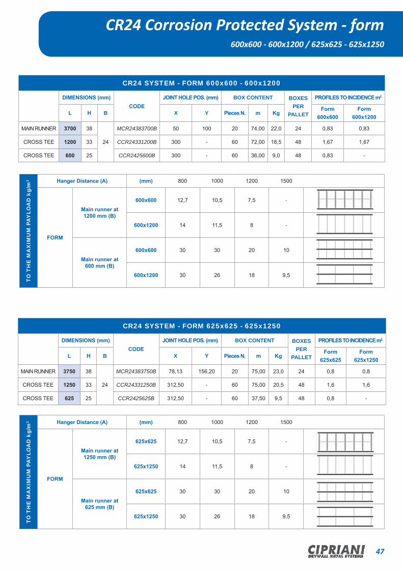
CR24 SYSTEM - FORM 600x600 - 600x1200
DIMENSIONS (mm)CODE
JOINT HOLE POS. (mm) BOX CONTENT BOXES PER
PALLET
PROFILES TO INCIDENCE m2
L H B X Y Pieces N. m KgForm
600x600Form
600x1200
MAIN RUNNER 3700 38
24
MCR24383700B 50 100 20 74,00 22,0 24 0,83 0,83
CROSS TEE 1200 33 CCR24331200B 300 - 60 72,00 18,5 48 1,67 1,67
CROSS TEE 600 25 CCR2425600B 300 - 60 36,00 9,0 48 0,83 -
CR24 SYSTEM - FORM 625x625 - 625x1250
DIMENSIONS (mm)CODE
JOINT HOLE POS. (mm) BOX CONTENT BOXES PER
PALLET
PROFILES TO INCIDENCE m2
L H B X Y Pieces N. m KgForm
625x625Form
625x1250
MAIN RUNNER 3750 38
24
MCR24383750B 78,13 156,20 20 75,00 23,0 24 0,8 0,8
CROSS TEE 1250 33 CCR24331250B 312,50 - 60 75,00 20,5 48 1,6 1,6
CROSS TEE 625 25 CCR2425625B 312,50 - 60 37,50 9,5 48 0,8 -
CR24 Corrosion Protected System - form600x600 - 600x1200 / 625x625 - 625x1250
TO T
HE
MA
XIM
UM
PAY
LOA
D k
g/m
2 Hanger Distance (A) (mm) 800 1000 1200 1500
FORM
Main runner at1200 mm (B)
600x600 12,7 10,5 7,5 -
600x1200 14 11,5 8 -
Main runner at600 mm (B)
600x600 30 30 20 10
600x1200 30 26 18 9,5
TO T
HE
MA
XIM
UM
PAY
LOA
D k
g/m
2 Hanger Distance (A) (mm) 800 1000 1200 1500
FORM
Main runner at1250 mm (B)
625x625 12,7 10,5 7,5 -
625x1250 14 11,5 8 -
Main runner at625 mm (B)
625x625 30 30 20 10
625x1250 30 26 18 9,5
48 CIPRIANI DRYWALL METAL SYSTEMS
HD15 System TeetaniumTM
CR24 SYSTEM - FORM 610x610 – 610x1220
DIMENSIONS (mm)CODE
JOINT HOLE POS. (mm) BOX CONTENT BOXES PER
PALLET
PROFILES TO INCIDENCE m2
L H B X Y Pieces N. m KgForm
610x610Form
610x1220
MAIN RUNNER 3657,6 38
24
MCR24383658B 76,20 152,40 20 73,15 21,0 24 0,82 0,82
CROSS TEE 1219,2 33 CCR24331220B 304,80 - 60 73,15 20,0 48 1,64 1,64
CROSS TEE 609,6 25 CCR2425610B 304,80 - 60 36,58 9,5 48 0,82 -
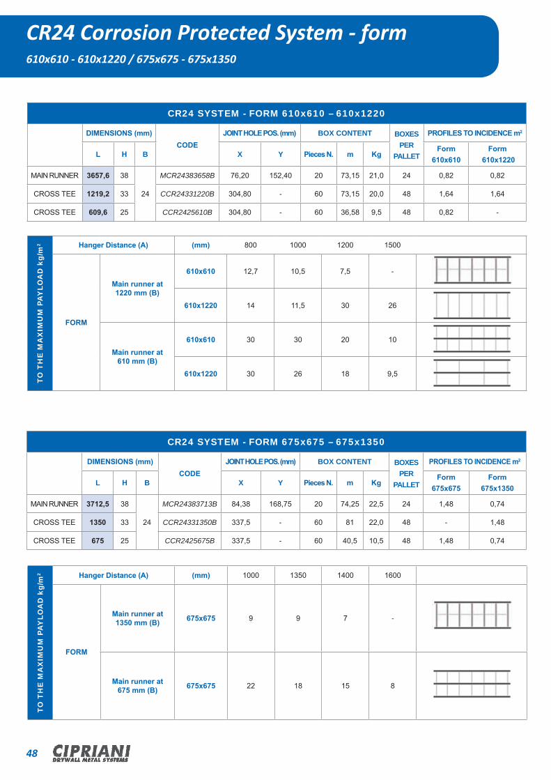
CR24 Corrosion Protected System - form610x610 - 610x1220 / 675x675 - 675x1350
CR24 SYSTEM - FORM 675x675 – 675x1350
DIMENSIONS (mm)CODE
JOINT HOLE POS. (mm) BOX CONTENT BOXES PER
PALLET
PROFILES TO INCIDENCE m2
L H B X Y Pieces N. m KgForm
675x675Form
675x1350
MAIN RUNNER 3712,5 38
24
MCR24383713B 84,38 168,75 20 74,25 22,5 24 1,48 0,74
CROSS TEE 1350 33 CCR24331350B 337,5 - 60 81 22,0 48 - 1,48
CROSS TEE 675 25 CCR2425675B 337,5 - 60 40,5 10,5 48 1,48 0,74
TO T
HE
MA
XIM
UM
PAY
LOA
D k
g/m
2 Hanger Distance (A) (mm) 800 1000 1200 1500
FORM
Main runner at1220 mm (B)
610x610 12,7 10,5 7,5 -
610x1220 14 11,5 30 26
Main runner at610 mm (B)
610x610 30 30 20 10
610x1220 30 26 18 9,5
TO T
HE
MA
XIM
UM
PAY
LOA
D k
g/m
2 Hanger Distance (A) (mm) 1000 1350 1400 1600
FORM
Main runner at1350 mm (B) 675x675 9 9 7 -
Main runner at675 mm (B) 675x675 22 18 15 8

49CIPRIANI DRYWALL METAL SYSTEMS
HD15 System TeetaniumTM
Exposed 15mm “T” GridClick-on Overlapping Assembly
C
HANGER PERIMETER PROFILE
MAIN RUNNER
600 CROSS TEE1200 CROSS TEE
BA
ACCESSORIES page number reference 63
C.039 - HANGING RODS V WIRE LW302006
MAIN RUNNER
1200 CROSS TEE
600 CROSS TEE
38
15
38
15
38
15
X
YYX
X X
X
L
X X
X
L
L
Structure according to EN 13964.
Fire Proofing Certification - n progress.
Standard colours: White – Black – Silver (other colours available on demand).
Corrosion resistance according to Standards UNI EN 13964 B class.
For profiles with different lengths, make a specific request to CIPRIANI PROFILATI.
The load per square meter should be uniformly distributed (not granted additional load points). The arrow of flexion was calculated in accordance with the class 1 (L/500) of EN 13964, providing that the installation of the substructure takes place as shown in the drawings.
Concentrated loads or additional weights such as lights, smoke detectors, air ducts, suspended signs, etc..are not allowed.
The maximum loads per m2 shown in the table include panels’ weight and any additional weight such as mineral wool or glass fiber to improve the acoustic and fire resistance features.

50 CIPRIANI DRYWALL METAL SYSTEMS
HD15 SYSTEM - FORM 600x600 – 600x1200
DIMENSIONS (mm)CODE
JOINT HOLE POS. (mm) BOX CONTENT BOXES PER
PALLET
PROFILES TO INCIDENCE m2
L H B X Y Pieces N. m KgForm
600x600Form
600x1200
MAIN RUNNER 3700
38 15
M15383700B 50 100 20 74,00 22,2 24 0,83 0,83
CROSS TEE 1200 C15381200B 300 - 60 72,00 20,4 48 1,67 1,67
CROSS TEE 600 C1538600B 300 - 60 36,00 10,2 48 0,83 -
HD15 SYSTEM - FORM 625x625 – 625x1250
DIMENSIONS (mm)CODE
JOINT HOLE POS. (mm) BOX CONTENT BOXES PER
PALLET
PROFILES TO INCIDENCE m2
L H B X Y Pieces N. m KgForm
625x625Form
625x1250
MAIN RUNNER 3750
38 15
M15383750B 78,13 156,20 20 75,00 22,5 24 0,8 0,8
CROSS TEE 1250 C15381250B 312,50 - 60 75,00 21,2 48 1,6 1,6
CROSS TEE 625 C1538625B 312,50 - 60 37,50 11,6 48 0,8 -
HD15 System - form600x600 - 600x1200 / 625x625 - 625x1250
TO T
HE
MA
XIM
UM
PAY
LOA
D k
g/m
2 Hanger Distance (A) (mm) 800 1000 1200 1500
FORM
Main runner at1200 mm (B)
600x600 11,5 8,5 6 -
600x1200 12 9,5 6,5 -
Main runner at600 mm (B)
600x600 20 20 15 7
600x1200 20 20 15 7,5
TO T
HE
MA
XIM
UM
PAY
LOA
D k
g/m
2 Hanger Distance (A) (mm) 800 1000 1200 1500
FORM
Main runner at1250 mm (B)
625x625 11,5 8,5 6 -
625x1250 12 9,5 6,5 -
Main runner at625 mm (B)
625x625 20 20 15 7
625x1250 20 20 15 7,5

51CIPRIANI DRYWALL METAL SYSTEMS
HD15 SYSTEM - FORM 610x610 – 610x1220
DIMENSIONS (mm)CODE
JOINT HOLE POS. (mm) BOX CONTENT BOXES PER
PALLET
PROFILES TO INCIDENCE m2
L H B X Y Pieces N. m KgForm
610x610Form
610x1220
MAIN RUNNER 3657,6
38 15
M15383658B 76,20 152,40 20 73,15 22,0 24 0,82 0,82
CROSS TEE 1219,2 C15381220B 304,80 - 60 73,15 20,8 48 1,64 1,64
CROSS TEE 609,6 C1538610B 304,80 - 60 36,58 11,4 48 0,82 -
HD15 System - form610x610 - 610x1220 / 675x675 - 675x1350
HD15 SYSTEM - FORM 675x675 – 675x1350
DIMENSIONS (mm)CODE
JOINT HOLE POS. (mm) BOX CONTENT BOXES PER
PALLET
PROFILES TO INCIDENCE m2
L H B X Y Pieces N. m KgForm
675x675Form
675x1350
MAIN RUNNER 3712,5
38 15
M15383713B 84,38 168,75 20 74,25 22,0 24 1,48 0,74
CROSS TEE 1350 C15381350B 337,5 - 60 81 20,0 48 - 1,48
CROSS TEE 675 C1538675B 337,5 - 60 40,5 10,5 48 1,48 0,74
TO T
HE
MA
XIM
UM
PAY
LOA
D k
g/m
2 Hanger Distance (A) (mm) 800 1000 1200 1500
FORM
Main runner at1220 mm (B)
610x610 11,5 8,5 6 -
610x1220 12 9,5 6,5 -
Main runner at610 mm (B)
610x610 20 20 15 7
610x1220 20 20 15 7,5
TO T
HE
MA
XIM
UM
PAY
LOA
D k
g/m
2 Hanger Distance (A) (mm) 800 1000 1200 1500
FORM
Main runner at1350 mm (B) 675x675 13 13 10 -
Main runner at675 mm (B) 675x675 22 18 15 8

52 CIPRIANI DRYWALL METAL SYSTEMS
HD35 System TeetaniumTM
Exposed 35mm “T” GridClick-on Overlapping Assembly
C
HANGER PERIMETER PROFILE
MAIN RUNNER
1200 CROSS TEE1200 CROSS TEE
BA
MAIN RUNNER
1200 CROSS TEE
600 CROSS TEE
X
YY38
35
38
35
35
38
X
X X
X
L
X X
X
L
L
ACCESSORIES page number reference 63
C.039 - HANGING RODS V WIRE LW302006
Structure according to EN 13964.
Fire Proofing Certification - In progress.
Standard colours: White – Black – Silver (other colours available on demand).
Corrosion resistance according to Standards UNI EN 13964 B class.
For profiles with different lengths, make a specific request to CIPRIANI PROFILATI.
The load per square meter should be uniformly distributed (not granted additional load points). The arrow of flexion was calculated in accordance with the class 1 (L/500) of EN 13964, providing that the installation of the substructure takes place as shown in the drawings.
Concentrated loads or additional weights such as lights, smoke detectors, air ducts, suspended signs, etc..are not allowed.
The maximum loads per m2 shown in the table include panels’ weight and any additional weight such as mineral wool or glass fiber to improve the acoustic and fire resistance features.
53CIPRIANI DRYWALL METAL SYSTEMS
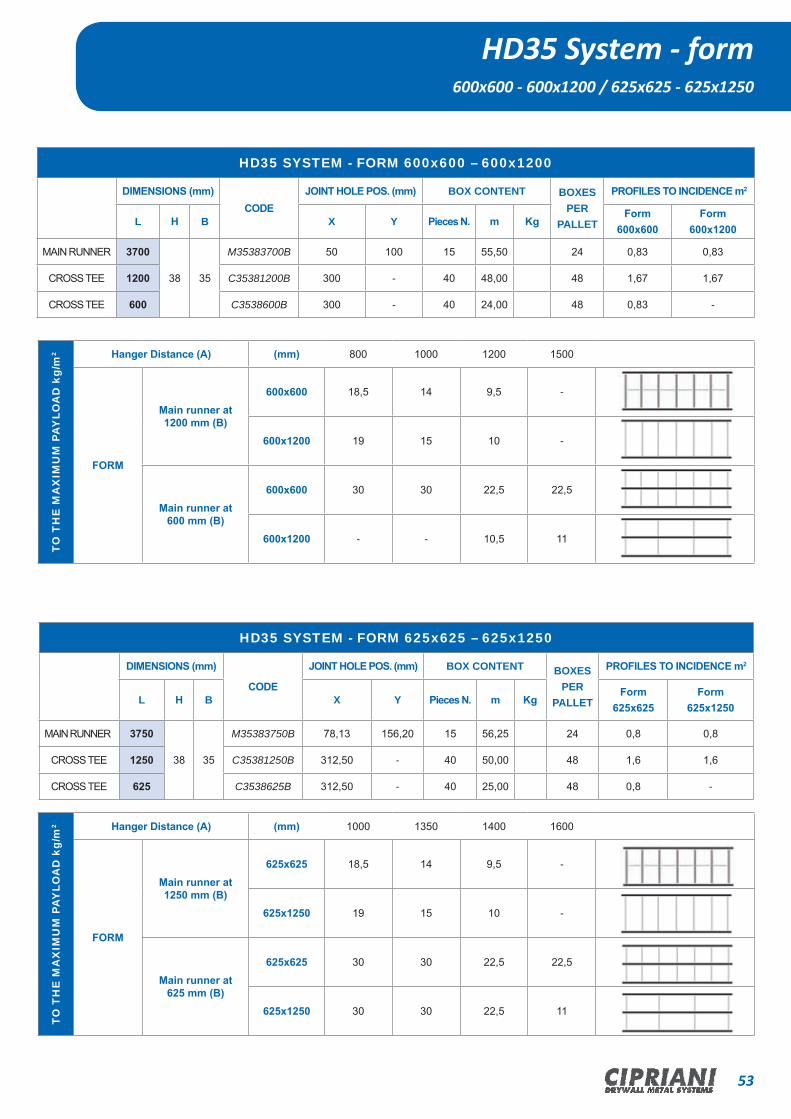
HD35 SYSTEM - FORM 600x600 – 600x1200
DIMENSIONS (mm)CODE
JOINT HOLE POS. (mm) BOX CONTENT BOXES PER
PALLET
PROFILES TO INCIDENCE m2
L H B X Y Pieces N. m KgForm
600x600Form
600x1200
MAIN RUNNER 3700
38 35
M35383700B 50 100 15 55,50 24 0,83 0,83
CROSS TEE 1200 C35381200B 300 - 40 48,00 48 1,67 1,67
CROSS TEE 600 C3538600B 300 - 40 24,00 48 0,83 -
HD35 SYSTEM - FORM 625x625 – 625x1250
DIMENSIONS (mm)
CODE
JOINT HOLE POS. (mm) BOX CONTENT BOXES PER
PALLET
PROFILES TO INCIDENCE m2
L H B X Y Pieces N. m KgForm
625x625Form
625x1250
MAIN RUNNER 3750
38 35
M35383750B 78,13 156,20 15 56,25 24 0,8 0,8
CROSS TEE 1250 C35381250B 312,50 - 40 50,00 48 1,6 1,6
CROSS TEE 625 C3538625B 312,50 - 40 25,00 48 0,8 -
HD35 System - form600x600 - 600x1200 / 625x625 - 625x1250
TO T
HE
MA
XIM
UM
PAY
LOA
D k
g/m
2 Hanger Distance (A) (mm) 800 1000 1200 1500
FORM
Main runner at1200 mm (B)
600x600 18,5 14 9,5 -
600x1200 19 15 10 -
Main runner at600 mm (B)
600x600 30 30 22,5 22,5
600x1200 - - 10,5 11
TO T
HE
MA
XIM
UM
PAY
LOA
D k
g/m
2 Hanger Distance (A) (mm) 1000 1350 1400 1600
FORM
Main runner at1250 mm (B)
625x625 18,5 14 9,5 -
625x1250 19 15 10 -
Main runner at625 mm (B)
625x625 30 30 22,5 22,5
625x1250 30 30 22,5 11
54 CIPRIANI DRYWALL METAL SYSTEMS
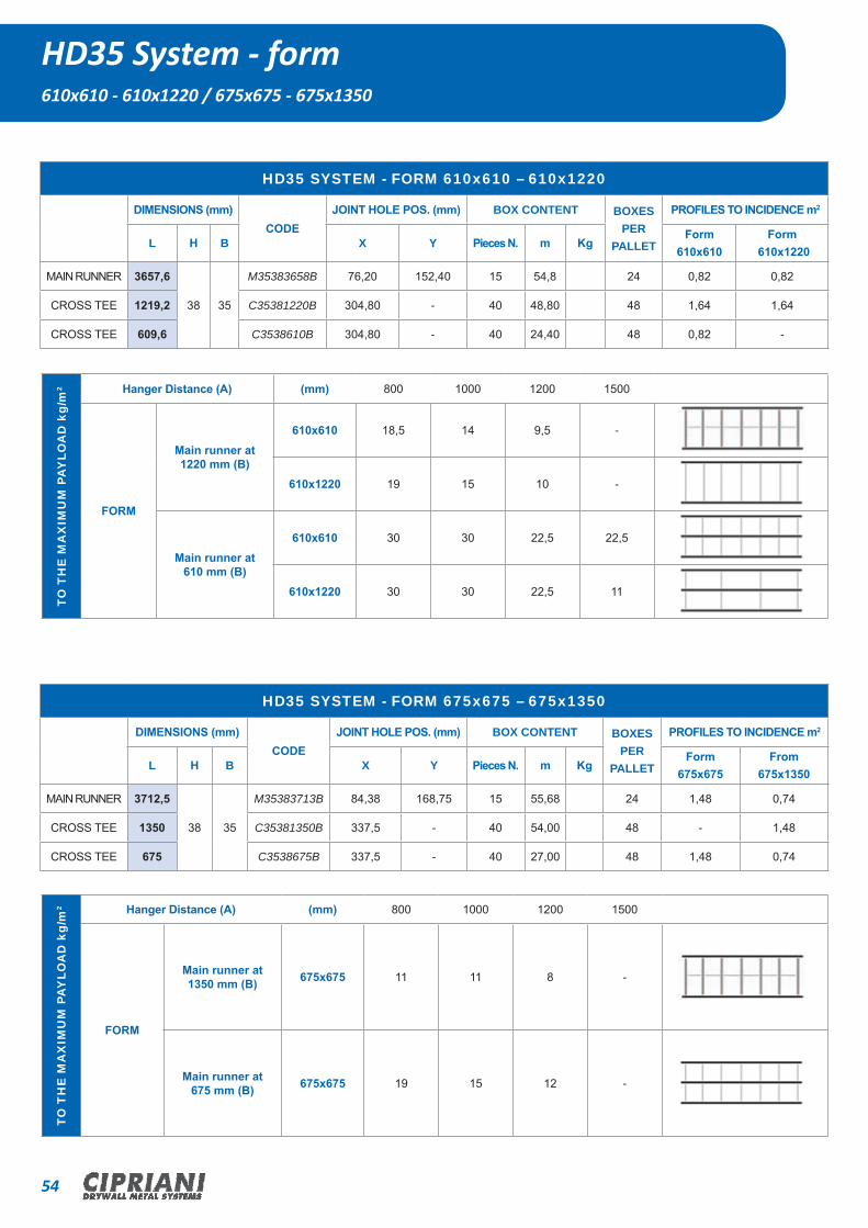
HD35 SYSTEM - FORM 610x610 – 610x1220
DIMENSIONS (mm)CODE
JOINT HOLE POS. (mm) BOX CONTENT BOXES PER
PALLET
PROFILES TO INCIDENCE m2
L H B X Y Pieces N. m KgForm
610x610Form
610x1220
MAIN RUNNER 3657,6
38 35
M35383658B 76,20 152,40 15 54,8 24 0,82 0,82
CROSS TEE 1219,2 C35381220B 304,80 - 40 48,80 48 1,64 1,64
CROSS TEE 609,6 C3538610B 304,80 - 40 24,40 48 0,82 -
HD35 System - form610x610 - 610x1220 / 675x675 - 675x1350
HD35 SYSTEM - FORM 675x675 – 675x1350
DIMENSIONS (mm)CODE
JOINT HOLE POS. (mm) BOX CONTENT BOXES PER
PALLET
PROFILES TO INCIDENCE m2
L H B X Y Pieces N. m KgForm
675x675From
675x1350
MAIN RUNNER 3712,5
38 35
M35383713B 84,38 168,75 15 55,68 24 1,48 0,74
CROSS TEE 1350 C35381350B 337,5 - 40 54,00 48 - 1,48
CROSS TEE 675 C3538675B 337,5 - 40 27,00 48 1,48 0,74
TO T
HE
MA
XIM
UM
PAY
LOA
D k
g/m
2 Hanger Distance (A) (mm) 800 1000 1200 1500
FORM
Main runner at1220 mm (B)
610x610 18,5 14 9,5 -
610x1220 19 15 10 -
Main runner at610 mm (B)
610x610 30 30 22,5 22,5
610x1220 30 30 22,5 11
TO T
HE
MA
XIM
UM
PAY
LOA
D k
g/m
2 Hanger Distance (A) (mm) 800 1000 1200 1500
FORM
Main runner at1350 mm (B) 675x675 11 11 8 -
Main runner at675 mm (B) 675x675 19 15 12 -
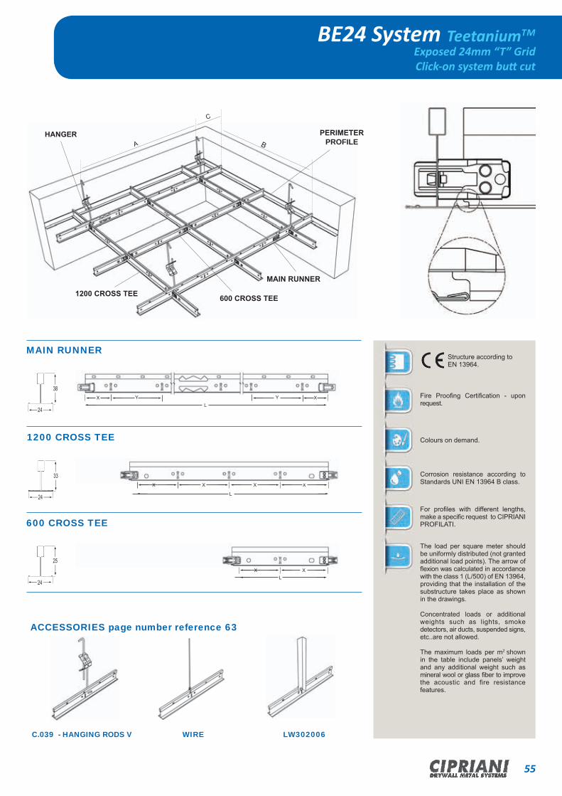
55CIPRIANI DRYWALL METAL SYSTEMS
BE24 System TeetaniumTM
Exposed 24mm “T” GridClick-on system butt cut
C
HANGER PERIMETER PROFILE
MAIN RUNNER
600 CROSS TEE1200 CROSS TEE
BA
ACCESSORIES page number reference 63
C.039 - HANGING RODS V WIRE LW302006
MAIN RUNNER
1200 CROSS TEE
600 CROSS TEE
24
25
38
24
33
24
YYX X
L
Structure according to EN 13964.
Fire Proofing Certification - upon request.
Colours on demand.
Corrosion resistance according to Standards UNI EN 13964 B class.
For profiles with different lengths, make a specific request to CIPRIANI PROFILATI.
The load per square meter should be uniformly distributed (not granted additional load points). The arrow of flexion was calculated in accordance with the class 1 (L/500) of EN 13964, providing that the installation of the substructure takes place as shown in the drawings.
Concentrated loads or additional weights such as lights, smoke detectors, air ducts, suspended signs, etc..are not allowed.
The maximum loads per m2 shown in the table include panels’ weight and any additional weight such as mineral wool or glass fiber to improve the acoustic and fire resistance features.
XX X
L
X X
X
L

56 CIPRIANI DRYWALL METAL SYSTEMS
BE24 SYSTEM - FORM 600x600 – 600x1200
DIMENSIONS (mm)CODE
JOINT HOLE POS. (mm) BOX CONTENT BOXES PER
PALLET
PROFILES TO INCIDENCE m2
L H B X Y Pieces N. m KgForm
600x600Form
600x1200
MAIN RUNNER 3700 38
24
MA24383700B 50 100 20 74,00 20,5 24 0,83 0,83
CROSS TEE 1200 33 CA24331200B 300 - 60 72,00 17,0 48 1,67 1,67
CROSS TEE 600 25 CA2425600B 300 - 60 36,00 7,5 48 0,83 -
BE24 SYSTEM - FORM 625x625 – 625x1250
DIMENSIONS (mm)CODE
JOINT HOLE POS. (mm) BOX CONTENT BOXES PER
PALLET
PROFILES TO INCIDENCE m2
L H B X Y Pieces N. m KgForm
625x625Form
625x1250
MAIN RUNNER 3750 38
24
MA24383750B 78,13 156,20 20 75,00 21,5 24 0,8 0,8
CROSS TEE 1250 33 CA24331250B 312,50 - 60 75,00 18,5 48 1,6 1,6
CROSS TEE 625 24 CA2425625B 312,50 - 60 37,50 8,5 48 0,8 -
BE24 System - form600x600 - 600x1200 / 625x625 - 625x1250
TO T
HE
MA
XIM
UM
PAY
LOA
D k
g/m
2 Hanger Distance (A) (mm) 800 1000 1200 1500
FORM
Main runner at1200 mm (B)
600x600 12,7 10,5 7,5 -
600x1200 14 11,5 8 -
Main runner at600 mm (B)
600x600 30 30 20 10
600x1200 30 26 18 9,5
TO T
HE
MA
XIM
UM
PAY
LOA
D k
g/m
2 Hanger Distance (A) (mm) 800 1000 1200 1500
FORM
Main runner at1250 mm (B)
625x625 12,7 10,5 7,5 -
625X1250 14 11,5 8 -
Main runner at625 mm (B)
625x625 30 30 20 10
625X1250 30 26 18 9,5

57CIPRIANI DRYWALL METAL SYSTEMS
BE24 SYSTEM - FORM 610x610 – 610x1220
DIMENSIONS (mm)CODE
JOINT HOLE POS. (mm) BOX CONTENT BOXES PER
PALLET
PROFILES TO INCIDENCE m2
L H B X Y Pieces N. m KgForm
610x610Form
610x1220
MAIN RUNNER 3657,6 38
24
MA24383658B 76,20 152,40 20 73,15 19,5 24 0,82 0,82
CROSS TEE 1219,2 33 CA24331220B 304,80 - 60 73,15 17,5 48 1,64 1,64
CROSS TEE 609,6 25 CA2425610B 304,80 - 60 36,58 8,0 48 0,82 -
BE24 System - form610x610 - 610x1220 / 675x675 - 675x1350
BE24 SYSTEM - FORM 675x675 – 675x1350
DIMENSIONS (mm)CODE
JOINT HOLE POS. (mm) BOX CONTENT BOXES PER
PALLET
PROFILES TO INCIDENCE m2
L H B X Y Pieces N. m KgForm
675x6725Form
675x1350
MAIN RUNNER 3712,5 38
24
MA24383713B 84,38 168,75 20 74,25 21,0 24 1,48 0,74
CROSS TEE 1350 33 CA24331350B 337,5 - 60 81 20,0 48 - 1,48
CROSS TEE 675 25 CA2425675B 337,5 - 60 40,5 10,0 48 1,48 0,74
TO T
HE
MA
XIM
UM
PAY
LOA
D k
g/m
2 Hanger Distance (A) (mm) 800 1000 1200 1500
FORM
Main runner at1220 mm (B)
610x610 12,7 10,5 7,5 -
610x1220 14 11,5 30 26
Main runner at610 mm (B)
610x610 30 30 20 10
610x1220 30 26 18 9,5
TO T
HE
MA
XIM
UM
PAY
LOA
D k
g/m
2 Hanger Distance (A) (mm) 1000 1350 1400 1600
FORM
Main runner at1350 mm (B) 675x675 9 9 7 -
Main runner at675 mm (B) 675x675 22 18 15 8
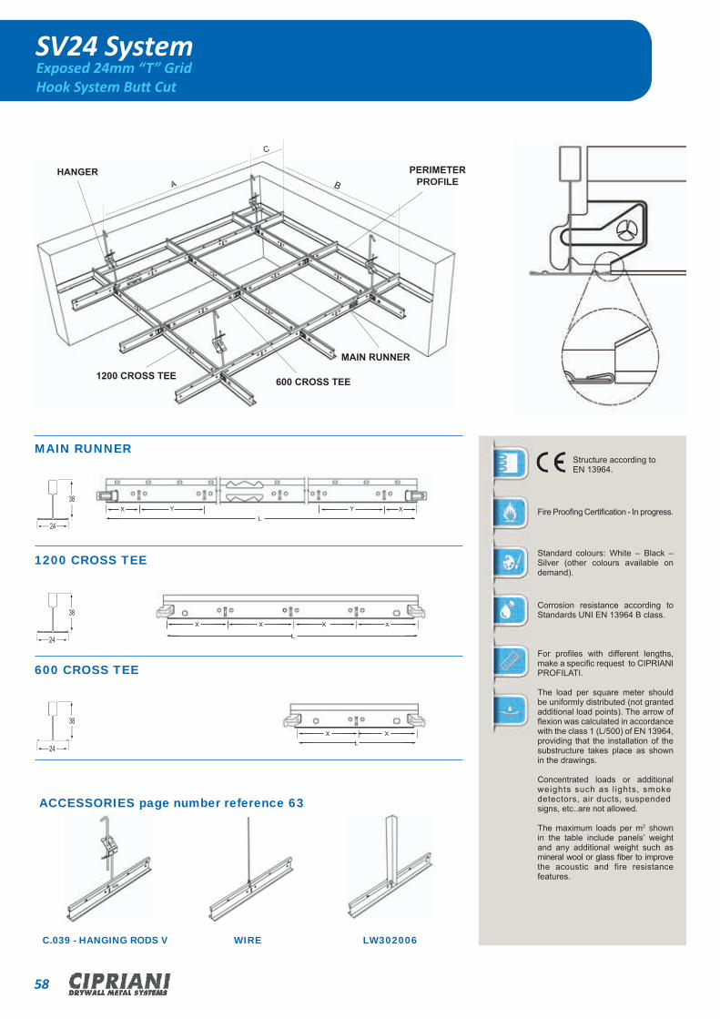
58 CIPRIANI DRYWALL METAL SYSTEMS
SV24 SystemExposed 24mm “T” GridHook System Butt Cut
C
HANGER PERIMETER PROFILE
MAIN RUNNER
600 CROSS TEE1200 CROSS TEE
BA
ACCESSORIES page number reference 63
C.039 - HANGING RODS V WIRE LW302006
structure according to EN 13964.
Fire Proofing Certification. In progress
The given value for thickness refers to the laminate steel that compose the galvani-zed steel profile.
Colours on demand.
Corrosion resistance according to Standards UNI EN 13964 B class.Résistance à la corrosion extra selon UNI EN13964 classe C (seulement sur demande).
On request is available a special traversio-ne length 300mm.
The load per square meter should be uniformly distributed (not granted additio-nal load points). The arrow of flexion was calculated in accordance with the class 1 (L/500) of EN 13964, providing that the installation of the substructure takes place as shown in the drawings.
MAIN RUNNER
1200 CROSS TEE
600 CROSS TEE
YY38
24
38
24
24
38
X X
L
Structure according to EN 13964.
Fire Proofing Certification - In progress.
Standard colours: White – Black – Silver (other colours available on demand).
Corrosion resistance according to Standards UNI EN 13964 B class.
For profiles with different lengths, make a specific request to CIPRIANI PROFILATI.
The load per square meter should be uniformly distributed (not granted additional load points). The arrow of flexion was calculated in accordance with the class 1 (L/500) of EN 13964, providing that the installation of the substructure takes place as shown in the drawings.
Concentrated loads or additional weights such as l ights, smoke detectors, air ducts, suspended signs, etc..are not allowed.
The maximum loads per m2 shown in the table include panels’ weight and any additional weight such as mineral wool or glass fiber to improve the acoustic and fire resistance features.
XX X
L
X X
X
L

59CIPRIANI DRYWALL METAL SYSTEMS
SV24 SYSTEM - FORM 600x600 - 600x1200
DIMENSIONS (mm)CODE
JOINT HOLE POS. (mm) BOX CONTENT BOXES PER
PALLET
PROFILES TO INCIDENCE m2
L H B X YPieces
N.m Kg
Form 600x600
Form600x1200
MAIN RUNNER 3700
38 24
P24383700B 50 100 20 74,00 25,3 24 0,83 0,83
CROSS TEE 1200 IA24381200B 300 - 60 72,00 21,6 48 1,67 1,67
CROSS TEE 600 TA2438600B 300 - 60 36,00 12,8 48 0,83 -
SV24 SYSTEM - FORM 625x625 - 625x1250
DIMENSIONS (mm)CODE
JOINT HOLE POS. (mm) BOX CONTENT BOXES PER
PALLET
PROFILES TO INCIDENCE m2
L H B X Y Pieces N. m KgForm
625x625Form
625x1250
MAIN RUNNER 3750
38 24
P24383750B 78,13 156,20 20 75,00 25,7 24 0,8 0,8
CROSS TEE 1250 IA24381250B 312,50 - 60 75,00 22,6 48 1,6 1,6
CROSS TEE 625 TA2438625B 312,50 - 60 37,50 11,3 48 0,8 -
SV24 System - form600x600 - 600x1200 / 625x625 - 625x1250
TO T
HE
MA
XIM
UM
PAY
LOA
D k
g/m
2 Hanger Distance (A) (mm) 800 1000 1200 1500
FORM
Main runner at1200 mm (B)
600x600 16 14 10 4,5
600x1200 16 14 10 5
Main runner at600 mm (B)
600x600 30 30 20 10
600x1200 30 26 18 9,5
TO T
HE
MA
XIM
UM
PAY
LOA
D k
g/m
2 Hanger Distance (A) (mm) 800 1000 1200 1500
FORM
Main runner at1250 mm (B)
625X625 16 14 10 4,5
625X1250 16 14 10 5
Main runner at625 mm (B)
625X625 30 30 20 10
625X1250 30 26 18 9,5

60 CIPRIANI DRYWALL METAL SYSTEMS
SV24 System - form610x610 - 610x1220
SV24 SYSTEM - FORM 610x610 – 610x1220
DIMENSIONS (mm)CODE
JOINT HOLE POS. (mm) BOX CONTENT BOXES PER
PALLET
PROFILES TO INCIDENCE m2
L H B X YPieces
N.m Kg
Form610x610
Form610x1220
MAIN RUNNER 3657,6
38 24
P24383658B 76,20 152,40 20 73,15 25,0 24 0,82 0,82
CROSS TEE 1219,2 IA24381220B 304,80 - 60 73,15 25,0 48 1,64 1,64
CROSS TEE 609,6 TA2438610B 304,80 - 60 36,58 11,0 48 0,82 -
TO T
HE
MA
XIM
UM
PAY
LOA
D k
g/m
2 Hanger Distance (A) (mm) 800 1000 1200 1500
FORM
Main runner at1220 mm (B)
610x610 16 14 10 4,5
610x1220 16 14 10 5
Main runner at610 mm (B)
610x610 30 30 20 10
610x1220 30 26 18 9,5

61CIPRIANI DRYWALL METAL SYSTEMS
L-W-F Perimeter Profiles - Special Profiles
PROFILE DESCRIPTION TYPE BOX CONTENT
L-Shaped perimeter profile
thickness 0,50
(Length 3.000mm)
L-19-B 50 150 28,0
L-Shaped perimeter profile
thickness 0,50
(Length 3.000mm)
L-24-B 50 150 31,0
L-Shaped perimeter profile
thickness 0,50
(Length 3.000mm)
L-30-B 30 90 23,5
L-Shaped perimeter profile
thickness 0,50
(Length 3.000mm)
L-29-B 50 150 29,0
L-Shaped perimeter profile
thickness 0,50
(Length 3.000mm)
L-32-B 40 120 23,8
Double L-Shaped perimeter profile
thickness 0,50
(Length 3.000mm)
W-10-B 25 75 20,4
F-Shaped profile for vertical joint
thickness 0,50
(Length 3.000mm)
F-13-B 14 42 16,1
F-Shaped profile for vertical joint
thickness 0,50
(Length 3.000mm)
F-16-B 12 36 14,2
Pieces N. m kg
SECTION PROFILE CODE LENGTH BOX CONTENT
Spacer profile APD 600/625 10 1,5
Short cross bar 24x38mmHook-on Assembly
TA-24-38-300-B TA-24-38-305-BTA-24-38-312-B
300305
312,5120
10,811,011,3
Short cross bar 15x38mmHook-on Assembly
TA-15-38-300-BTA-15-38-305-BTA-15-38-312-B
300305
312,5120
10,211,411,6
Main runner length on demand P2438P1538 on demand - 20,4
(mm) Pieces n. kgDescription
19
24
24
24
30
30
12
24
19
10
38
33
13
21,5
38
35
21,5
16
50 100
29
19
32
19

62 CIPRIANI DRYWALL METAL SYSTEMS
Technical SpecificationsACCESSORIES REQUIREMENT
ACCESSORIES REQUIRED PER SQUARE METER.
The values reported in this page are purely indicative and they can change depending on the extension of the interested area. In particular for perimeter profiles, the reported values are based on average values, not considering any scrap or assembly waste. All values refer to 1 sqm of false ceiling.
MAIN RUNNER POSITION
(mm)
CEILING TILE SIZE
(mm)
PERIMETRAL TRIM
(m)
PANEL CLIPS
(n°)
HANGERS AND FASTENERS
(n°)
1200 600x600 0,70 5,56 0,70
1200 600x1200 0,70 5,56 0,70
600 600x600 0,70 5,56 1,40
600 600x1200 0,70 5,56 1,40
1250 625x625 0,70 5,12 1,50*
1250 625x1250 0,70 2,56 1,50*
625 625x625 0,70 5,12 1,50*
625 625x1250 0,70 2,56 1,50*
(*) Quantity defined by Standards DIN 18168.
HANGER
1200 CROSS TEE 600 CROSS TEE
MAIN RUNNER
PERIMETER TRIM

63CIPRIANI DRYWALL METAL SYSTEMS
Technical Specifications - LOADS TABLE
PERIMETER PROFILES
The reported values refer to the maximum static load that can be applied, considering the profile’s projecting arm and a maximum camber of 1/300 of the projection measurement.
The profile fixing elements are considered a maximum distance of 300mm and load is considered to be evenly distributed.
PROFILE THICKNESS PROJECTION MAX LOAD
(mm) (mm) (Kg/m)
L-19 0,5 19 6,7
L-24 0,5 24 6,5
W-10 0,5 31 6,3
ACCESSORIES
The reported values refer to the most commonly used type of hanging systems and are purely given as an indication.
ACCESSORIES MAX LOAD (Kg)
DOUBLE WOVEN WIRE 31
HOOK WITH SPRING AND HANGING ROD 15
DOUBLE SPRING WITH HANGING RODS 25
ACCESSORY DESCRIPTION CODE BOXPieces N.
WEIGHTKg/package
AccessoryDOUBLER SPRING C.039 100 1,65
AccessoryHOOK WITH SPRING C.066 100 3,35
AccessoryWIRE
HDG STEEL Ø 2mm- - -
AccessoryCORNER
L 20 x 20 galvanizedL 25 x 25 galvanized
LW202005LW252505 - -
ACCESSORY: descriptionpage
number reference
HANGING RODS 47

64 CIPRIANI DRYWALL METAL SYSTEMS
GYPS42 System TeebuildTM
Structure T 42mmfor plasterboard
A
B
C
Max
wei
ght
allo
wed
per
su
spen
ded
ceili
ng s
quar
e Distance between centres – Suspension
(mm)800 1000 1100 1200
Distance between centres of the main
runner 1200 mm 22 kg/m2 16 kg/m2 13 kg/m2 10 kg/m2
Distance between centres of the main
runner 600 mm 40 kg/m2 35 kg/m2 29 kg/m2 22 kg/m2
structure according to EN13964 - EN14195
Fire resistance class A1.
Corrosion resistance standard – B class.
A MAX 1200 mmB MAX 400 mmC MAX 400 mmD 500 mm
X = 50 mmY = 100 mmZ = 300 mm
The load per square meter must be evenly distributed (additional charge points are not admitted). The camber has been calculated accordingly to class 1 (L/500) of the EN 13964, granted that structure assembly occurs as described in the drawings.
Concentrated loads or additional weights such as lights, smoke detectors, air ducts, suspended signs, etc..are not allowed.
The maximum loads per m2 shown in the table include panels’ weight and any additional weight such as
HANGER PERIMETER PROFILE
MAIN RUNNER
1200 CROSS TEE D
MAIN RUNNER - M42383700
CROSS TEE - C42381200
CROSS TEE - C4238600
38
42
38
42
42
38
PROFILE PERIMETER - UW413005 da 3 m30
41
YYX X
3700
ZZ Z
1200
Z Z
Z
600

Authorized Dealer
2014 Edition
CIPRIANI PROFILATI
Company Headquarter:Piazza Luigi di Savoia, 22 - 20124 Milano (MI) - Italy
Operating and Administrative Haedquarter:Via Pineta, 31 - 38068 Rovereto (TN) - Italy
Tel: +39 0464 02 03 77Fax: +39 0464 02 03 85
Registration VAT Number:IT01173470228
CIPRIANI DRYWALL METAL SYSTEMS