ds europe by s2tech srl
TRANSCRIPT
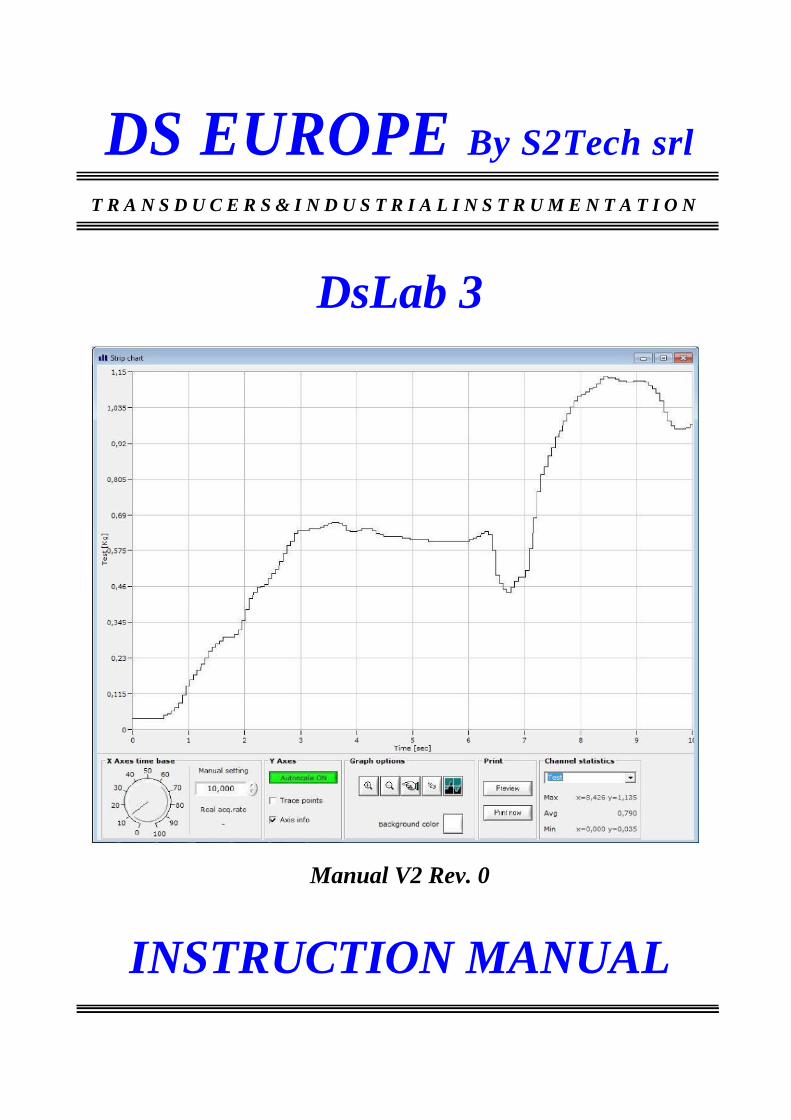
DS EUROPE By S2Tech srl T R A N S D U C E R S & I N D U S T R I A L I N S T R U M E N T A T I O N
DsLab 3
Manual V2 Rev. 0
INSTRUCTION MANUAL

- 2/31 -
DOCUMENT REVISIONS
Software Version
V 3.3.0
Manual Version
V2 R0
Notes
The information contained in this manual is subject to change without notice. S2Tech accepts no responsibility for any errors contained herein or for incidental or consequential damages resulting from the furnishing, performance or use of this material. Is prohibited - without prior written consent - any reproduction, adaptation, or translation of this manual, or parts thereof.
S2Tech srl –DsLab3 Instruction Manual

- 3/31 -
INTRODUCTION
1. This manual is an integral part of the supply and is delivered with the material, even if not listed on the
invoice. Moreover, it can be sent on request during the negotiation of purchase if the customer mentions
the application to which it is intended.
The number of supplied manuals can drop to a single copy, unless otherwise requested by the Customer,
for orders where multiple measurement systems are delivered.
2. Products covered by this manual are designed and manufactured for general use and, as consequence, it
is not possible to specify every possible application of the limits of use. It is mandatory for the
Customer the introduction of security measures to avoid damage to persons or property and damages of
shutdowns, etc.
In the case of dangerous uses, it is required to the User to inform the Supplier, so that additional safety
measures can be suggested or forgo ordering and delivery.
3. Instruments hereafter described are not certified measuring instruments and Customer is obliged to verify
the compliance of the instrument to his needs.
4. Instruments hereafter mentioned, even if connected to transducers or otherwise, are only parts of
machinery or equipment; they are sold in thousands of pieces every year for disparate applications,
having to meet different regulations always not known to the Supplier; S2Tech is forced to refuses all
responsibility of Use indicating in this manual and the most elementary precautions essential for proper
use, or best practices usual for the application of these devices in general purpose applications.
It is underlined the need – for the Customer - for a complete and specific insurance coverage particularly
when these machines are intended to countries such as the U.S. and Canada.
5. Instruments produced by S2Tech are of high professional quality, are rugged and designed for maximum
safety and reliability and the limitations and precautions hereafter listed are willing to underline to the
Customer/User the importance of avoiding any possible damage.
6. During production, instruments undergo several intermediate inspections and a final inspection that
includes test functionality of all features.
7. Periodically, random sampling is performed, and electrical, thermal, and mechanical tests are performed
to verify production conformity to product specifications.
As above, guarantees that the product has been shipped in perfect working order.
S2TECH S.r.l.
Via Imperia 28
20142 MILANO Tel. 02 8910142
Fax. 02 89124848
www.s2tech.it E-mail : [email protected]
S2Tech srl –DsLab3 Instruction Manual

- 4/31 -
SUMMARY 1. Introduction ....................................................................................... 5
2. Requirements..................................................................................... 5
Computer 5
Measurement instrument ................................................................................................................. 5
Performance of measurement system ............................................................................................. 5
Measuring limits of the acquisition system .................................................................................... 7
3. Software installation ......................................................................... 8
Installation sequence: ...................................................................................................................... 9
Activation code (CAN & Modbus) ............................................................................................... 10
4. Use of the DSLab3 program .......................................................... 11
Checks before execution ............................................................................................................... 11
Execution ...................................................................................................................................... 12
Establishing the connection .......................................................................................................... 13
S2Tech Connection Settings for CAN products ........................................................................... 14
Impostazione dei dati da visualizzare – Channel Manager ........................................................... 15
Modbus mode ............................................................................................................................ 15
CAN mode ................................................................................................................................. 16
5. Data acquisition ............................................................................... 22
Program Interface .......................................................................................................................... 22
Acquisition Menu – acquisition type......................................................................................... 22
File Menu .................................................................................................................................. 24
Channel Menu ........................................................................................................................... 25
Display Menu ............................................................................................................................ 25
Software Menu .......................................................................................................................... 25
Acquisition interface ..................................................................................................................... 26
Numerical data display window ................................................................................................ 26
System status Window .............................................................................................................. 27
Strip Charts Window ................................................................................................................. 28
6. Conditions of sale ............................................................................ 31
S2Tech srl –DsLab3 Instruction Manual

1. Introduction
DsLab3 software allows data acquisition from general purpose instruments,
supporting CANopen protocol and specific instruments of S2Tech with Modbus
protocol.
2. Requirements
Computer DsLab3 software can be installed on Windows 32-bit operating systems and is
compatible with Windows 2000, Windows XP (Home or Professional), Windows
Vista, Windows 7 (32 and 64 bit) and 8 (32 and 64 bit).
NOTE: For good quality of the measurements is good to pay great attention to
the quality of the earth connections used for the different components of the
measurement system and for all the components of the application, such as
inverters or other power organs that can generate electrical noise.
Take care not to cause earth loops, making sure that the measuring system has
common earth connections, as short as possible.
Measurement instrument
DsLab3 software allows the measurement and the transfer of data acquired
from the following S2Tech products, using the CANopen protocol and Modbus
RTU protocol:
• PITAGORA, firmware version 2.11 or higher.
• CANopen digital Load Cells, firmware (CM3_2013) or higher.
• CANopen digital Pressure Transducers, firmware (CM3_2013) higher. • CANopen Magnetostrictive Transducers,. firmware 1.00 (CM3_2014) or
higher
• CANopen 942DBCan Strain Link, (CM3_2009) or higher
• All S2Tech transducers / instruments with Modbus RTU protocol
Performance of measurement system
The transfer of the measured data, from the instrument to the computer, is a
function of:
• Connection speed, as set for the connection, and quality of the
connection itself;
• Characteristics of the USB connection on your computer (prefer USB 2.0
connections);
• Length of the connections for the CAN or Modbus network (RS485);
• Performance of the computer used for the measurement, of the
operating system, the capacity of the video card (limitations will result in

- 6/31 -
the operation of the measuring system using a video card without a
dedicated memory; in such case it is advisable to turn off real-time
preview of the acquired signal);
• Number of sensors / devices present and active on the CAN or Modbus
network.
• A/D Sampling frequencies used to sample the phenomena to be
detected, set in the individual measuring instruments.
For the characteristics and type of the CAN connections, refer to what is
available on the website www.can-cia.org.
S2Tech srl –DsLab3 Instruction Manual

- 7/31 -
Measuring limits of the acquisition system
The performance of the measurement system are affected by the number of
channels to be measured, by the number of devices on the CAN or Modbus
network, by the way data are published on the network by the different
devices, by the length of the connections and the characteristics of the
computer used for the management of the measures. The graphical
visualization of a large number of channels needs a greater workload at the
expense of performance. If fast acquisitions is needed, it may be necessary to
exclude the strip chart visualization.
In the program, moreover, are considered the following operating parameters:
Parameter Can Modbus RS485 Modbus RS232 e
USB
N. max channels 8 / device 8 / device 8 / device
N.max device 127 255 1
Available
readings/channel
1 ( PDO
Factory set )
13 ( selectable by
the User in the
measure field)
13 (selectable by the
User in the measure
field)
Min. Sync value 5msec - -
Max. Sync value 60sec - -
Although not specifically indicated, S2Tech reserves the right to make changes
or variations in view of a constant and continuous improvement of the product.
The above is provided as an indication, as a result of the tests conducted by us
on the test computer.
S2Tech srl –DsLab3 Instruction Manual

- 8/31 -
3. Software installation
DsLab3 software communicates with devices using two protocols: Modbus and CAN. The software installation must be performed by a Windows user who has administrative rights.
The installation CD-ROM, supplied by S2Tech, install on Your computer the
following drivers:
• By selecting CANopen, the driver for the IXXAT USB to Can converter is installed (driver vci_218_setup.exe).
• By selecting USB, the drivers for the USB version of PITAGORA is
installed (driver VCPDriver.exe - Virtual Com Port).
• By selecting RS232/RS485, no additional driver will be installed, and you can communicate via Modbus protocol, on any installed RS232 or RS485 serial com port.
If there are problems installing the driver CANopen, refer to the documentation that came with the IXXAT CAN interface or the IXXAT web site ( www.ixxat.de ).
DsLab3 software is supplied on CD-ROM, or can be downloaded from the
website at www.s2tech.it .
The installation creates a DsLab3 folder in the Program Files directory. The installation software creates, in Start \ All Programs, a link to the software and an icon is set up on the desktop.
S2Tech srl –DsLab3 Instruction Manual
- 9/31 -
Installation sequence:
1. Insert the CD and run the setup.exe file. The setup includes the installation
files necessary for the application and installation of the needed drivers
(CAN / Modbus) for communication with the device.
2. Pitagora CAN - At this stage do not connect the USBtoCAN interface to
the PC (if you are using the device Can).
3. After software installation a restart of your computer is needed.
4. Connect USBtoCAN interface (only for devices Can) and finish the
installation of the operating system files needed for the proper
management of the interface. At the end of the installation process, verify
that the USB LED on the IXXAT interface is turned on, signaling that the
device connection is working properly. Note that USBtoCAN interface will be
properly handled by Your computer if it is always inserted on the USB port
where it has been installed the first time.
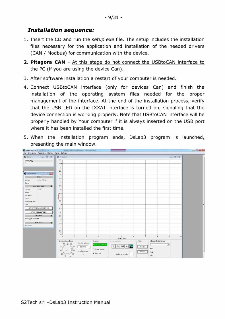
5. When the installation program ends, DsLab3 program is launched,
presenting the main window.
S2Tech srl –DsLab3 Instruction Manual

- 10/31 -
Activation code (CAN & Modbus)
Measurement system is provided with a paper/PDF sheet containing the
activation code linked to the type of interface to use.
• For IXXAT interface USB to CAN, code is tied to the serial number of the
interface (eg. HW123456)
• For the Modbus protocol it is linked to the serial number of the instrument,
shown on the label on the top of the instrument, or shown on the display
during the power on (eg SN 1234)
If the interface is not provided by S2Tech, at the purchase the program prior
notice must be given indicating the serial number of the interface You intend to
use, so that and activation code can be generated for the program You wish to
use. Product activation and binding to the Instrument’s serial number is
required for all devices.
Prior activation, make sure You have connected to the computer's USB port the
USB/CAN interface (USB LED powered on).
When first acquisition is activated (FAST, LONG
or DELAYED) a window is presented where you
must enter the activation code.
Type it, as shown in the provided
documentation.
This procedure is performed at the first use of the program and is no longer
performed if the program accepts the input code.
If a new instrument/USBtoCAN interface is connected to the program, then a
new activation code is needed and the program will not acquire any
measurements until the activation procedure is correctly ended.
S2Tech srl –DsLab3 Instruction Manual

- 11/31 -
4. Use of the DSLab3 program
Checks before execution
Before You run the program DsLab3, verify that:
a) The measurement system, consisting of the transducer connected to the
measuring instrument PITAGORA or other CANopen / Modbus
transducers or devices are working correctly.
b) In the case of CAN connection, the measuring system should be
connected to the IXXAT CAN interface installed in the PC (Green LED
powered on, close to the USB CAN / USB converter label) and that the
CAN bus is terminated with two 120 ohm resistors, to both ends, if You
do not use the wiring and equipment supplied by S2Tech S.r.l. Proper
selection of network cable is important (twisted pairs, shielded CAN cable
to be used).
c) If the DSLab3 program works as MASTER CAN on the network (NMT
functions active and/or SYNC activated) there must not be other units on
the network that operate as CAN MASTER.
d) Is USB connection has been chosen, verify that the Virtual COM port is
present on the list of the peripheral active on the computer.
S2Tech srl –DsLab3 Instruction Manual
- 12/31 -
Execution
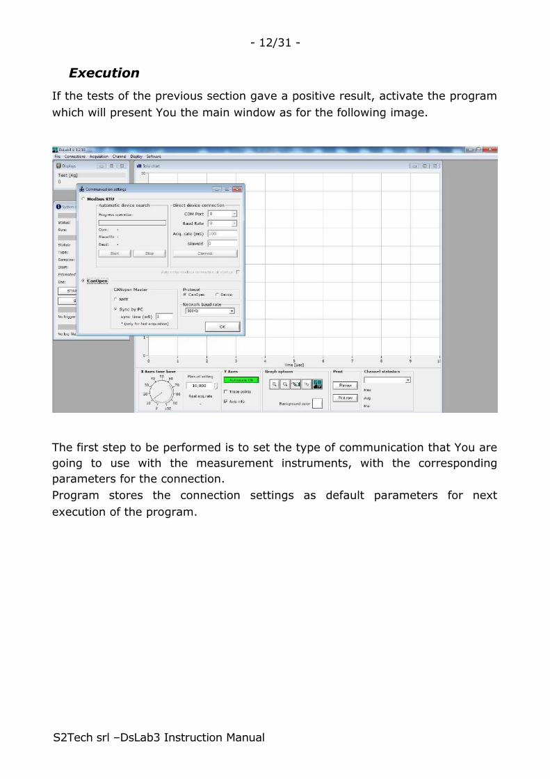
If the tests of the previous section gave a positive result, activate the program
which will present You the main window as for the following image.
The first step to be performed is to set the type of communication that You are
going to use with the measurement instruments, with the corresponding
parameters for the connection.
Program stores the connection settings as default parameters for next
execution of the program.
S2Tech srl –DsLab3 Instruction Manual

- 13/31 -
Establishing the connection
The [Communication settings] window allows you to set the connection
parameters with the device, which may be via CAN or Modbus.
CAN connection settings
• Network baud rate – sets the transmission speed of the network.
• CANopen Master
o NMT enabled - Enable the services CANopen Network Management
(NMT) of DsLab3.
o Sync enabled – Enables the SYNC Master of DsLab3.
• Protocol
o CanOpen – select the CANopen protocol.
o Deimo – select the Deimo protocol
(NOT SUITABLE for general purpose applications)
NOTE: Under normal conditions, the DsLab3’s SYNC service is ENABLED, and is
needed to disable NMT and Sync solely if on the network there is another
CANopen master.
S2Tech srl –DsLab3 Instruction Manual

- 14/31 -
S2Tech Connection Settings for CAN products
For a measurement chain consists solely of products provided by S2Tech srl,
use the following configuration, unless otherwise indicated in consideration of
the characteristics of the application.
Parameter Value Note
Network baud rate 500Kb
NMT Active
Sync Active
Protocol CANopen
ID 26
If the measurement system is not working, check the CAN LED placed on the
CAN/USB adapter. If it is not powered on or it is red, check the connections of
the network, verify the presence of the two line terminating resistors and verify
that all attached devices are set with parameters corresponding to those set in
the communications program.
S2Tech srl –DsLab3 Instruction Manual

- 15/31 -
Impostazione dei dati da visualizzare – Channel Manager
The [Channel Manager] window, also recalled with the Channel menu \ Setup
is used to set the channels to be acquired and displayed on the strip chart
graph, on the numeric displays and to be save on the data files. Depending on
the connection type and used protocol, this window may presents different
data fields for setting the characteristics of the channels.
Modbus mode
The S2Tech Modbus device, when properly connected to the PC, is queried by
the DSLab program, at the start, in order to know the hardware installed on
the different available slot. The term "slot" refers to a data acquisition card
installed inside the instrument PITAGORA (depending on the configuration
required at time of order).
Each slot provides a set of measurements that can be converted into
"channels", to be display and handled by the DsLab3 software.
Each channel is defined as the sum of the selection performed using the drop
down list "Slot", referable to the slot of interest (A, B, C or D) and the drop
S2Tech srl –DsLab3 Instruction Manual

- 16/31 -
down list "Measure" where the measurement type is selected among those
available for the selected slot.
Enter through the box "Label" the name/description of the channel You are
going to set up and a unit of measure by means of the box "Eng.Unit".
For each channel it is also possible then to configure:
1. Linearization / conversion of measures (Linearization).
2. Properties of numeric digital displays (Display properties) and graph
representation of the measured data (Chart trace properties).
3. Trigger activated acquisition (Trigger options)
In order to apply the desired settings to the Channel of interest, select it from
the "Channel List" table, so that the channel that you want to change settings
is active. confirms the selection of the channel object
for changes to the acquisition parameters (in the example, channel 1 has been
selected).
The pushbutton allows you to define a new channel. If you select
from the list of available channels an existing channel as template, after
setting the appropriate information of Node reference and Mapping for the new
channel (not the same as an existing channel), by pressing this button You will
create the new channel, based on the settings of the existing channel.
The pushbutton is used to confirm and save all the settings
and / or variations made to the selected channel.
Use instead the pushbutton to remove and delete the selected
channel (no confirmation is asked).
CAN mode
Configuration
The Configuration block configures the
measures to display.
The basic data are:
• Node – CANopen node, from
which it to be taken the PDO that
contains the data to be acquired, shown (strip chart and/or numeric
display) and saved.
• Mapping – Chooses the portion of the PDO that carries the data of
interest and the location of the data within the PDO. The suffix "a" refers
to the first 4 bytes of the PDO, while the suffix "b" indicates the last 4
bytes of the PDO selected.
S2Tech srl –DsLab3 Instruction Manual
- 17/31 -
PDO-1a PDO-1b
PDO-2a PDO-2b
PDO-3a PDO-3b
PDO-4a PDO-4b
• Label – Label assigned by the User to the measure channel.
• Unit - Units of measure (optional) to be displayed next to the acquired
value.
• Channel type – channels defined on the channel list may be Rea! (linked
to an existing physical resource (A/D channel) of the connected
Instrument, or Virtua!, if they are the defined as the result of
math operations on real channels (optional feature)
The configuration of the channel, relatively to the CAN network, is required to
indicate to the program the characteristics of the data packets, said PDO, in the
CAN network (Node and reference PDO) so to associate the measurement units,
the display characteristics and / or conversion into mechanical units or the
different display properties. An instrument can make available different types of
data and this requires the selection of information (such as PDO type) to be
used for the acquisition of the measure of interest.
S2Tech default configuration parameters
Each instrument on the CAN network is characterized by a unique node
reference (NODE). This parameter, in addition to the baud rate is needed to
connect to the instrument and receive the available measures.
According to the type of instrument to which You are connecting, different type
of measures may be available. Please refer to the connected product’s
instruction manual, for a list of the available measurement and their
description.
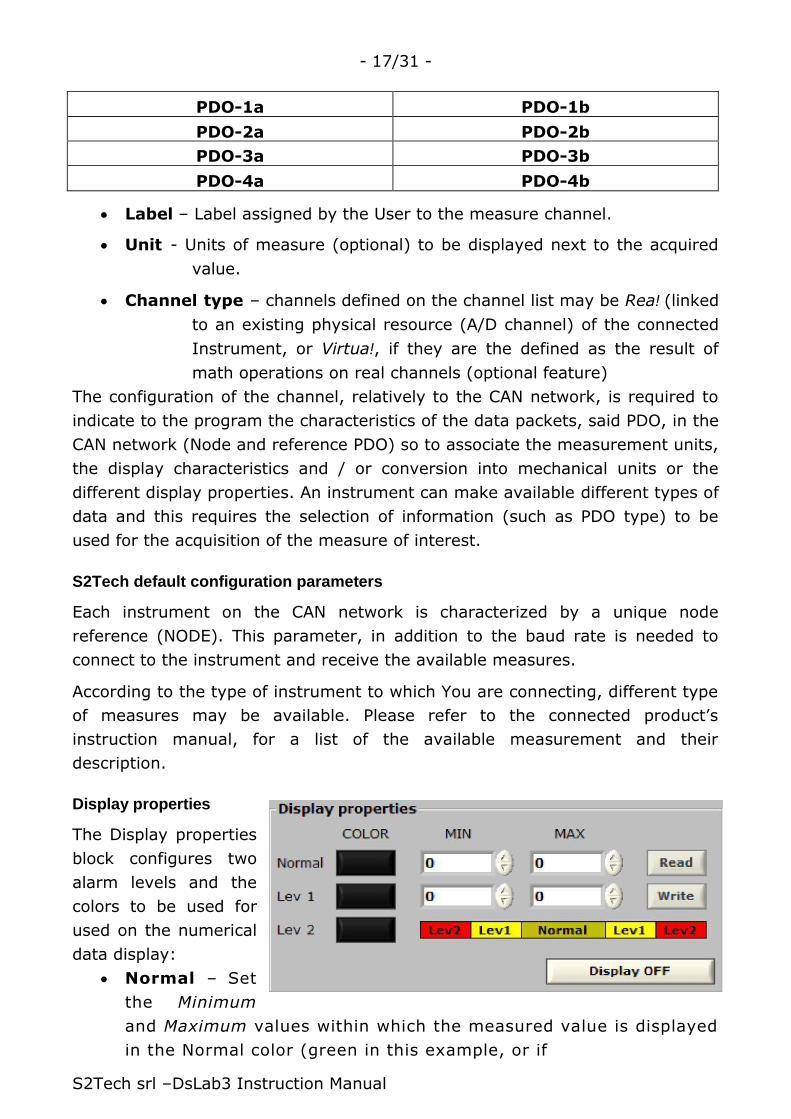
Display properties
The Display properties
block configures two
alarm levels and the
colors to be used for
used on the numerical
data display:
• Normal – Set
the Minimum
and Maximum values within which the measured value is displayed
in the Normal color (green in this example, or if
S2Tech srl –DsLab3 Instruction Manual

- 18/31 -
Normal MIN ≤ measurement ≤ Normal MAX).
• Level 1 – Set the Minimum and Maximum values within which the value
of the measurement is displayed in the color Lev 1 (in Yellow for the
above example), if Lev 1 MIN ≤ measure ≤ Normal MIN or Normal MAX
≤ measure ≤ Lev 1 MAX.
• Level 2 – Sets the color used for displaying of the measurement, when
the measurement value exceeds / is larger than the limits set for Lev 1
(in Red, measur3 ≤ Lev 1 Min and measure ≥ Lev 1 MAX).
The program requires and checks that the values of the limits
of the Normal zone are internal to the values of limits of zone
Lev1, as well as the numerical values of the limits set for Lev1
must be internal to the values set for the Lev2.
The pushbutton / activates /
deactivates the numeric display of the selected channel.
DECIMAL POINT setting in Display properties
The decimal point position is automatically set by the program.
To change the decimal point position, modify it directly on the setup menu of
the PITAGORA instrument so that any change is automatically transferred to
the computer (for the procedure, see section 6 of the PITAGORA instruction
manual).
When connecting to a PITAGORA instrument, DSLab queries the device for the
value of the PSDP parameter (see PITAGORA’s manual) and if value is defined
for the decimal point position, then also the acquired value on the DSLab will
be shown using the same settings of the instrument.
K factor
The K factor block configures, for each channel, a multiplier
coefficient that is applied on the measurements of the channel
where it is needed a value different from 1 (no K effect on the measurements).
Each channel can have a different K value assigned and the defined value is
displayed on the channel list.
S2Tech srl –DsLab3 Instruction Manual

- 19/31 -
Chart trace properties
The Chart trace properties block configure the color and
line thickness of the line corresponding to the selected
channel for the Strip Chart graphical display of the acuired
data; pushbutton /
enables or disables the graphical
representation of the selected track.
By pressing the Color pushbutton you set the color of the graphical trace
that will be represented with a thickness equal to the amount set as Line width.
It is suggested to choose a high contrast color with reference to the
background chosen for viewing Strip Chart.
Consider the combination of the colors chosen in relation to the color of the
Cursor XY, used to display the numeric values from the waveform.
By setting the numerical values Y min and Y max, you set the display limits of
the Y axis for the selected channel, so to represent it properly when autoscaling
option is not in use.
Linearization
The Linearization block configures the parameters for the linearization of
measurement displayed on the PC, allowing the conversion of units of measure
(numeric display and Strip Charts); the data acquired by the instrument can be
used as received from the network (CAN or Modbus) or it can be converted by
an algorithm running locally on the PC; in the latter case it is necessary to set
the known points of reference for the linearization X0, Y0 and X1, Y1 enabling
the linearization function by means of the Enable control (as in the image); it is
possible to capture in real time the value of X0 and X1 from the instrument
for the selected channel, by means of pushbutton , placed to the left of
S2Tech srl –DsLab3 Instruction Manual
- 20/31 -
each control. X0 and X1 are expressed with engineering units and
resolution used internally by the instrument. For correct conversion, verify
that the value is different from X1 to X0, as should be also different Y0
from Y1.
Measurement and storing of X0 and X1 points can be performed only if the
Instrument is connected to the computer and the program is in position to
connect to it to perform the needed live measurement.
To display the resulting linearized value with a desired Decimal point position
set the appropriate value in the corresponding input field.
In example, to display two decimal enter 2 and insert the full scale value of Y1
with as integer.
EXAMPLES:
• If you want to have shown 10,00 Kg, enter 2 as decimal points and Y1
value 1000.
• If you want to see 10,000 Kg, enter 3 as decimal points and 10000 as Y1
value.
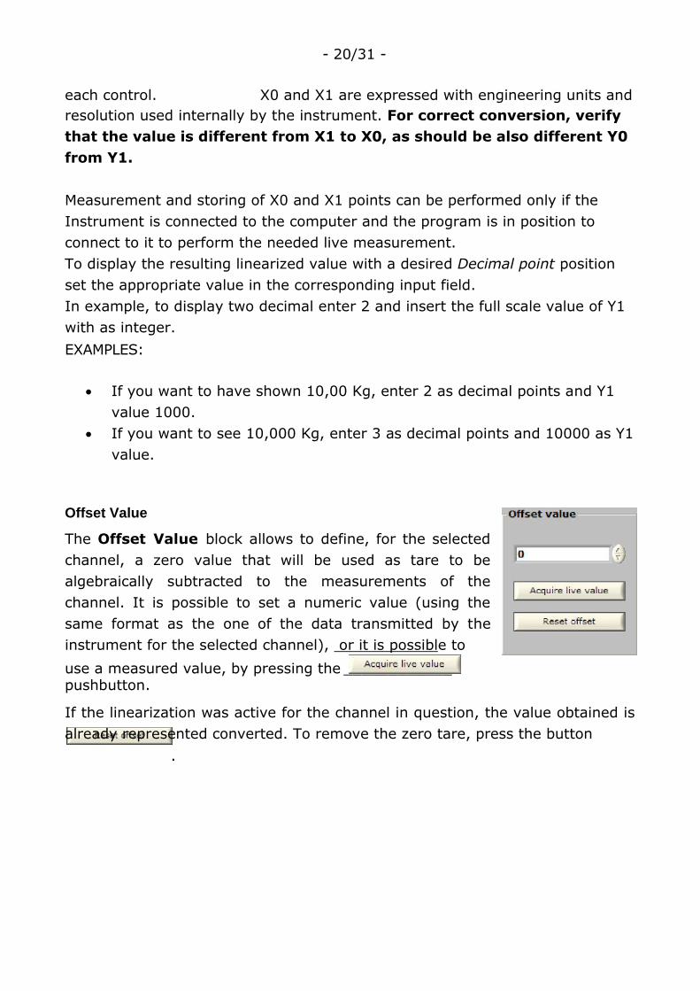
Offset Value
The Offset Value block allows to define, for the selected
channel, a zero value that will be used as tare to be
algebraically subtracted to the measurements of the
channel. It is possible to set a numeric value (using the
same format as the one of the data transmitted by the
instrument for the selected channel), or it is possible to
use a measured value, by pressing the ____________ pushbutton.
If the linearization was active for the channel in question, the value obtained is
already represented converted. To remove the zero tare, press the button
.

Trigger options
The Trigger option block allows you to set a trigger
threshold (trigger value) for only one of the available
channels. According to what has been set as logical
condition, you will have the activation of the
acquisition (with display and optional data storage) if
the value:
S2Tech srl –DsLab3 Instruction Manual

- 21/31 -
measure > set Trigger value, or if
measure < set Trigger value
The pushbutton / ________________ allows you to enable /
disable the trigger mode corresponding to the threshold set.
The program indicates the activation of this function in the "System status",
showing the channel and the set trigger value.
Before trigger condition is reached, the program displays the measurements
only through numerical display (if enabled).
Measurements data are displayed (numerical and Strip Charts) and stored in
the log file solely when the trigger condition is met.
The acquisition of the waveforms on the Strip Chart graph is temporary
stopped by opening other windows or by activating other functions.
The above affects only the graphical displaying and it is therefore advisable to
prepare all the necessary settings before starting an acquisition, so to capture
the view in its entirety.
S2Tech srl –DsLab3 Instruction Manual

- 22/31 -
5. Data acquisition
Program Interface
Through the use of the menu bar and the graphic interface of the program it is
possible to set how measurements must be acquired and represented.
Acquisition Menu – acquisition type
Allows to start the acquisition of measurements, by selecting the measurement
mode that allows the best representation of the phenomenon of interest.
• Acquisition\FAST: This measurement mode is suitable to capture fast
phenomena and is characterized by a high utilization of computer
resources (graphics, data processing and storage, if you wish to save the
data on your hard disk). To make possible the graphic display, in this
mode of operation are displayed a reduced number of acquired points
(10%). Stopping the acquisition of the program will rebuild the display of
the acquired measurements, with 100% of the measured data.
This acquisition mode has to be stopped manually, using the button
available from the System Status panel, from which
it is also possible to start the
acquisition, by using the button .
• Acquisition\ONLY FILE (hi-speed sync use):
starts acquisition WITHOUT the graphic representation of the
measurements on the strip-chart (blind acquisition); this mode allows
you to capture data at the maximum possible speed (in relation to the
management of operating system processes), avoiding that the overhead
of drawing the graphics may slow down the collection of data with
possible loss of data. The status panel (System status) informs that a
"blind" acquisition has been activated.
By activating this acquisition You will be asked for the name of the data
file that will contain the acquired measurements. During the acquisition,
the acquired data are displayed on the numeric display, for those
channels where this setting is enabled in the Channel Manager.
S2Tech srl –DsLab3 Instruction Manual

- 23/31 -
• Acquisition\DELAYED: activate acquisition with a delay set by the user. It is
possible to delay
the start of
any type of
acquisition, for a
predefined number
of seconds set by
the user.
Cannot exist –
simultaneously -
two conditions for the beginning of the acquisitions, so you need to
disable any trigger conditions set on a single channel, to have that this
acquisition mode work properly. The program requires that all the
necessary information for the selected measurement mode have been
entered. When activated, you will see a timer that shows the time
remaining before the start of the measurements. It 'possible to delay the
acquisition of a maximum of 10.000
seconds.
• Acquisition\LONG: this acquisition mode
is suitable to be used for relatively slow
phenomena, where the phenomenon is
properly sampled with a cadence
measurement set using the data entry
field "Sample every", ranging from 0.5 to
60 seconds.
The program ends after acquiring for a preset time, set by the user
in the "Duration" field, being able to make the acquisition last for a
maximum of 30 days. The acquisition can be ended, manually, by
pressing the button _______________ on the System Status panel.
• Acquisition-Stop: acquisition is ended. If acquisition was intended to save
data on a log file, it is closed.

S2Tech srl –DsLab3 Instruction Manual

- 24/31 -
File Menu
File\Create new log file: allows you to define the name and location of the data
file that you want to create. A standard Windows operating system input
window is called to define the file name and storage location.
When you set the file name it should be remembered that if you select the
name of an existing file, the data contained in it will be overwritten. The
program does not append any of the measures on existing data file.
File\Open log file: Opens a data file
previously acquired, so to be able to
display and analyze data.
Using the button a window opens
letting you select the files of interest.
The window displays basic information
related to the acquired channels, the
characteristics of the file (acquisition
duration and size), offering the
possibility to reproduce the channels
and the time window of interest.
It is possible to choose to work with all
the data contained in the file, taking
long time to process them if
phenomenon required a long time data
acquisition. Otherwise it is possible to
select a portion of interest, using the two
sliders "Acquisition time selection ", to
define the beginning and the end of the
area of interest for display and analysis of
acquired data.
The name of the file whose data are
plotted on the Strip Chart window is also reported on the top windows frame.
File info: contains some information about
the characteristics of the file.
S2Tech srl –DsLab3 Instruction Manual

.
- 25/31 -
Channel list selection: through this
section are selected channels of interest
so to show more clearly the details of the
channel (with the acquisition of multi-
channel), limiting also the processing
time for large files, obtained with high
sampling.
Having carried out the channel settings and time intervals of interest you can
export the data in a tabular format, such as text files, with the button The data
is exported as a list with columns delimited by a TAB, inserting the Timestamp
(in seconds) created during the acquisition, so to obtain all the information
necessary for proper handling of the acquired data, for example through a
spreadsheet.
NOTE: when you activate the acquisition having defined a data file, it will be
used by the program to store data in binary format, to be more efficient in
terms of performances.
The data file is closed at the end of the acquisition, when you use the
command Acquisition-Stop. When you start a new capture data, if you do
not define a new file name, the program uses the existing reference
and overwrites the previously stored data.
Having selected the channel and the time interval of interest, with the button
is generated a graph of the acquired measurements, using the maximum
definition allowed by the data acquired, while using the button
data visualization is achieved using 50% of the available data,
so you can quickly represent acquisitions characterized by a considerable
amount of data.
Channel Menu
Allows you to customize the display of the different channels that can be
acquired from the program.
Display Menu Zoom - : reduces the size of the display that represent the acquired
measurements as a numeric value. Zoom + : increases the size of the display that represent the acquired
measurements as a numeric value.
Software Menu

Displays the version of the program.
S2Tech srl –DsLab3 Instruction Manual

.
- 26/31 -
Acquisition interface
The User Interface provides several information and measurement
functions. Numerical data display window
Displays the measurement using the measurement
units defined in the "Channel Manager".
The dimensions of the display are
• increased with the function Display\Zoom +
• decreased with the function Display\Zoom -
The displays show the measured values for all channels
where "Display properties" was set to
It is possible to represent, at the
same time, measurements in expressed in A/D points or converted
measurements in engineering units via linearization. In this last case, the
decimal point is a function of the settings related to the conversion, for a
maximum of 3 digits after the decimal point.
S2Tech srl –DsLab3 Instruction Manual

- 27/31 -
System status Window
Indicates whether the acquisition is active (flashing
LED status indication and "STATUS START"), as well
as:
Information relating to the CAN network
• Connection Status
• Sync Value used to querry the devices in the
network to obtain measures
Information relating to the Modbus network
• Connection Status
• Rate of acquisition set
Informazioni relative all’acquisizione in corso
• Type (FAST / LONG / DELAYED / ONLY FILE)
• Sample rate, in seconds
• Date and start time of the acquisition
• The date and time scheduled for the end of the
acquisition (LONG and DELAYED acquisitions)
Pushbutton _____________ , to activate a FAST data acquisition.
Pushbutton __________________ , to terminate any type of active acquisition,
closing at the same time the data file on which the measures are eventually
saved.
Information regarding the trigger function for the activation of the acquisition
• Trigger Type (an increasing / decreasing measurement toward the set
trigger value)
Information about the data file created to store measures
• Name of the data file
Remember that each time a new acquisition is started, with a data file
associated to it, a new file name must be assigned, in order not to overwrite
the existing acquisitions. The program does not append any of the measures
on existing data file.
S2Tech srl –DsLab3 Instruction Manual

- 28/31 -
Strip Charts Window
Used to display graphically the data, as a strip chart, as live measurements
coming from configured channels or as data coming
from log files saved on hard disk.
Data is displayed with reference to a settable time base.
The X axis scaling is suggested by the program in
relation to the type and duration of the acquisition in
progress. It is possible to set manually the desired
value, indicating to the program the amplitude of each
division for the representation of data.
The displaying of the Y-axes can enabled or disabled by
selecting "Axis info". It is possible to activate ________ or
deactivate ___________ the autoscaling of the display of all
acquired channels.
This replaces what is set in the "Channel Manager", as minimum and maximum
for the representation of the measured data, with respect to its axis Y.
It is possible to set the background color on which are plotted the
acquired data.
It is also possible to activate the displaying of the acquired points
S2Tech srl –DsLab3 Instruction Manual
- 29/31 -
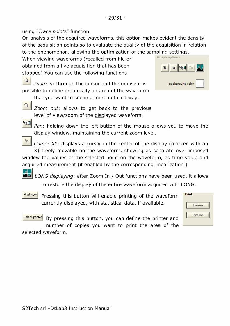
using "Trace points" function.
On analysis of the acquired waveforms, this option makes evident the density
of the acquisition points so to evaluate the quality of the acquisition in relation
to the phenomenon, allowing the optimization of the sampling settings.
When viewing waveforms (recalled from file or
obtained from a live acquisition that has been
stopped) You can use the following functions
Zoom in: through the cursor and the mouse it is
possible to define graphically an area of the waveform
that you want to see in a more detailed way.
Zoom out: allows to get back to the previous
level of view/zoom of the displayed waveform.
Pan: holding down the left button of the mouse allows you to move the
display window, maintaining the current zoom level.
Cursor XY: displays a cursor in the center of the display (marked with an
X) freely movable on the waveform, showing as separate over imposed
window the values of the selected point on the waveform, as time value and
acquired measurement (if enabled by the corresponding linearization ).
LONG displaying: after Zoom In / Out functions have been used, it allows
to restore the display of the entire waveform acquired with LONG.
Pressing this button will enable printing of the waveform
currently displayed, with statistical data, if available.
By pressing this button, you can define the printer and
number of copies you want to print the area of the
selected waveform.
S2Tech srl –DsLab3 Instruction Manual

- 30/31 -
S2Tech srl –DsLab3 Instruction Manual
The print preview windows shows information like the path of the log file from
which the plotted waveform has been loaded to be displayed, plus all the
statistical information calculated on the selected channel of interest.
Statistical block:
Allows to select from a drop down list the active
measurement channels.
After having selected the channel of interest, the program
compute the available statistics on the basis of a live
measurement or on the basis of a waveform loaded from a
log file previously saved on disk.

- 31/31 -
6. Conditions of sale
( f or a l l S2Tech products )
WARRANTY:
The number of electrical and mechanical controls carried out during production and final testing, performed on each
piece, ensures that the delivered product is free from defects in materials , workmanship and operation. The defective
product is returned after normal use within a period of 12 months from the shipment date will be repaired or
replacement free of charge at the S2Tech. Are charged to the Customer the cost of shipping, insurance, customs
clearance, etc. No warranty will be applied for misuse of the product .
In case of severe and non-repairable damages to the product the units could be returned disassembled, if no fee will be
paid by the Customer.
The instrument may contain a firmware or a software that is licensed to the Customer on a "as is" basis and it will
perform substantially in accordance with what is described in the manual.
S2Tech disclaims all other warranties, express or implied, including- among others - the warranties of merchantability
and fitness for a particular purpose, with respect to the hardware, firmware or software of the instrument and the
accompanying written materials. The warranty excludes all semiconductor integrated circuits, transistors, diodes,
microprocessors, memories, and what is excluded by any warranty by our suppliers. The delivered material must be
inspected within 10 days from the delivery and after this period must be considered accepted. S2Tech responsibility is
limited to the over mentioned and is declined any responsibility for damage to Persons or Properties or for damages due
to stop of machinery or equipment caused by the installation and use of products supplied (including, without
limitation, damages for loss or loss of profits , business interruption, loss of information or other pecuniary loss).
LIABILITY FOR DAMAGES:
S2Tech products are only parts of machinery and more complex equipment, sold in thousands of units per year, for
thousands of different applications with thousands of regulations and precautions for installation and use not known by
the Supplier. For any use or installation, which may directly or indirectly involve risk of injury or damage to Persons or
Properties, or damages for the stop of machinery or plant is a clear obligation of the Customer to inform immediately
S2Tech, before installing the product, which reserves the right to cease the negotiation or suspend the supply of the
product. S2Tech is available to suggest, without any responsibility, application hints or protection devices and
accessories, certification tests, Agencies or Consultancy specialized centers in order to reduce the risk of damage or
reset . It is also strongly recommended to read carefully the "instructions for installation and use " of the products that
can be sent - on request - during the commercial negotiation prior to the purchase of the goods and may be enclosed to
the shipment.
NOTE:
These "Conditions of Supply" are integral and complementary part of every bulletin, every invoice, every instruction
manual even if not expressly mentioned.
S2Tech srl.
S2Tech srl –DsLab3 Instruction Manual