ds1100 - fix intersection geometry check corridor: we will
TRANSCRIPT

119
DS1100 - Fix Intersection Geometry Check Corridor: we will check the STH25-4thAve corridor for errors and edit
This workflow demonstrates editing the intersection as follows:
• Fixes for the Corridor_STH25_4thAve corridor: o Adjust the beginning and end of the corridor regions to eliminate overlap or unintended gaps; o Fix the Curb to lane tapers on 4th Ave o Create geometry for variable width shoulders along intersection tapers; o Match shoulders to new polyline geometry; o Check for waterfalls; o Make sure Baselines and Regions do not extend too far or fall short of limits; o Fix the Curb Return lane target areas
Inputs:
• Corridor-STH25-4thAve.DWG Alignment/Profile Data Shortcuts EXIST surface data shortcut
Outputs: • Updated Corridor-STH25-4thAve.DWG
o Intersection offset geometry • Edge of lane alignments • Edge of widening alignments/Curb returns
o STH25-4thAve corridor

120
Notes:
1) When the intersection is first created the resulting corridor is not displayed correctly. We will Regen all (rea) to make sure it is displayed correctly. 2) We did not compute the limits of the intersection approaches correctly. This can be easily edited once we get the intersection the way we want it. 3) The intersection object does not create the variable width shoulder elements as per WisDOT Standard Detail Drawings. This is a very important aspect of our design. We will create these using basic AutoCad
commands and append them to the Corridor. 4) Our Curb Return Profiles were generated automatically by the Intersection Object. It is strongly suggested that they are displayed and checked to ensure a realistic solution. Pavement slopes in the curb
areas should be checked 5) Our curb return terraces are incorrect. 6) All corridors need to be checked for waterfall areas 7) Tapers on side road are straight-lined. This is incorrect taper method for curved roadways. 8) We did not daylight slopes behind curb radii. We will construct these slopes using Roadway Model refinement techniques in a future exercise.

121
1) Open the Corridor-STH25-4thAve.DWG. Rebuild STH25-4thAve corridor.
C3D Open Navigate to the \c3d\12345678\Design\Corridors folder Select the Corridor-STH25-4thAve.DWG Press Open Toolspace
Expand Corridors Right-Click STH25-4thAve corridor
Select Rebuild
Review Event Viewer messages.
Messages can be cleared Action→Clear All Events (optional step)
Dismiss the Event Viewer
Press the Green Checkmark button

122
2) Review corridor for errors and problems.
To inspect corridor in 3D: Select STH25-4thAve corridor from the drawing View ribbon→Navigate→ Orbit To return to Top view: Press Esc to exit Constrained Orbit mode Press Esc to deselect corridor View ribbon→Views→ Top Inspect the corridor for errors and mistakes in geometry and layout. To the right is a list of geometry errors we will address.
Straight-lined tapers on curved roadways are incorrect. This problem occurs on all four 4thAve tapers from curb to lane.
Intersection object does not create shoulder target objects to transition shoulder dimensions from normal roadway condition to acceleration/deceleration lane condition. This problem occurs on all 8 intersection tapers

123
Slope intercepts from intersecting roadways overlap behind curb radii. . This problem occurs in SW and NE quads.
Top View – SW Quad
Constrained Orbit View – SW Quad

124
Subgrade slope underneath curb doesn’t match subgrade slope under lane.

125
3) Review and edit STH25-4thAve corridor region stationing
Select the STH25-4thAve corridor Right-click→Corridor Properties Corridor Properties – STH25-4thAve dialog, Parameters tab
Note how when a Region is selected it is highlighted in the drawing Look for areas of Region overlap
BL9-RG8 overlaps with BL4-RG1 Change BL4-RG1 start station to 51+66.28' Press Apply
BL9-RG5 overlaps with BL3-RG1 Change BL3-RG1 end station to 48+33.56' Press Apply
BL10-RG9 overlaps with BL1-RG1 Change BL1-RG1 end station to 380+20.03' Press Apply
BL10-RG13 overlaps with BL2-RG1 Change BL2-RG1 start station to 389+19.82' Press Apply
Press OK C3D→Save

126
4) Change 4thAve straight line taper to curved taper. (SE quad)
Home ribbon→Layers→Layer Properties Layer Properties Manager
Select Corridor layer filter Freeze P_CRDR_FeatureLine, P_CRDR_PointMarker and P_CRDR_Link layers Select Roadway layer filter Make P_RDWY_LaneEdge the current layer Press X to close Layer Properties Manager
Home ribbon→Draw→Start, End, Radius arc command
Use Endpoint Osnap to place start point at the end of the back of curb corridor feature line. Use Endpoint Osnap to place end point at the end of the return taper created by the intersection object Key in radius value of 103.5 ft
Select newly create arc Right-Click→Convert to Polyline
New Polyline for curved taper

127
Select STH25-4thAve corridor Corridor: STH25-4thAve ribbon→Corridor Properties
Corridor Properties – STH25-4thAve dialog→Parameters tab Change BL9-RG8 start station to 50+81.28' Press Ellipsis button in BL9-RG8 Target field
Target Mapping dialog Select Object Name field for Width target of 4thAveR2L-LnGeneric (Right) subassembly
Set Width or Offset Target dialog
Change Object Type to Feature Lines, Survey Figures and Polylines Press Select from drawing button Select the curved taper polyline Press Enter
In the Selected entities to target: field
Select the STH25and4thAve-SE-Quadrant alignment Press the Red X button to remove this target Selection choice if multiple targets are found: Target to Farthest Offset
Press OK Press OK Press OK Keyin LAYTHW, press Enter to thaw corridor layers C3D→Save

128
Inspect changes in corridor
Before
After (with corridor visibility isolated)

129
5) Change 4thAve straight line taper to combination straight and curved taper. (NE quad)
Home ribbon→Layers→Layer Properties Layer Properties Manager
Select Corridor layer filter Freeze P_CRDR_FeatureLine and P_CRDR_Link layers Select Roadway layer filter Make P_RDWY_LaneEdge the current layer Press X to close Layer Properties Manager
Home ribbon→Draw→Create Line command
Use Endpoint Osnap to place start point at the end of the curb flange corridor feature line. Key in ‘SO Select 4thAve alignment Specify station along alignment: 5078 Specify offset: -14.3 Press Esc to exit transparent command Press Esc to exit Create line command
Home ribbon→Draw→Start, End, Radius arc command
Use Endpoint Osnap to place start point at the end of the line previously created (50+78) Use Endpoint Osnap to place end point at the end of the return taper created by the intersection object Key in radius value of 76.5 ft
Select newly created line and arc Key in Flatten Press Enter Remove hidden lines?: No Select newly created line Right-Click→Convert to Polyline Home ribbon→Modify→Join command Select source object: Select newly created line Select objects to join source: Select newly created arc Press Enter
New polyline for combination straight and curved taper
130
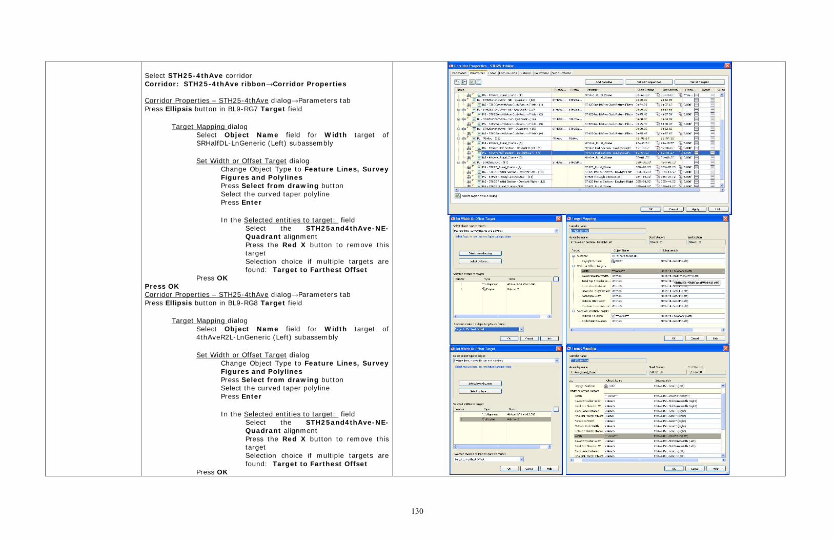
Select STH25-4thAve corridor Corridor: STH25-4thAve ribbon→Corridor Properties
Corridor Properties – STH25-4thAve dialog→Parameters tab Press Ellipsis button in BL9-RG7 Target field
Target Mapping dialog Select Object Name field for Width target of SRHalfDL-LnGeneric (Left) subassembly
Set Width or Offset Target dialog
Change Object Type to Feature Lines, Survey Figures and Polylines Press Select from drawing button Select the curved taper polyline Press Enter
In the Selected entities to target: field
Select the STH25and4thAve-NE-Quadrant alignment Press the Red X button to remove this target Selection choice if multiple targets are found: Target to Farthest Offset
Press OK Press OK Corridor Properties – STH25-4thAve dialog→Parameters tab Press Ellipsis button in BL9-RG8 Target field
Target Mapping dialog Select Object Name field for Width target of 4thAveR2L-LnGeneric (Left) subassembly
Set Width or Offset Target dialog
Change Object Type to Feature Lines, Survey Figures and Polylines Press Select from drawing button Select the curved taper polyline Press Enter
In the Selected entities to target: field
Select the STH25and4thAve-NE-Quadrant alignment Press the Red X button to remove this target Selection choice if multiple targets are found: Target to Farthest Offset
Press OK

131
Press OK Press OK Keyin LAYTHW, press Enter to thaw corridor layers C3D→Save
Before
After

132
6) Change 4thAve straight line taper to curved taper. (NW quad)
Home ribbon→Layers→Layer Properties Layer Properties Manager
Select Corridor layer filter Freeze P_CRDR_FeatureLine and P_CRDR_Link layers Select Roadway layer filter Make P_RDWY_LaneEdge the current layer Press X to close Layer Properties Manager
Home ribbon→Draw→Start, End, Radius arc command
Use Endpoint Osnap to place start point at the end of the back of curb corridor feature line. Use Endpoint Osnap to place end point at the end of the return taper created by the intersection object Key in radius value of 113.5 ft
Select newly create arc Right-Click→Convert to Polyline
New polyline for curved taper

133
Select STH25-4thAve corridor Corridor: STH25-4thAve ribbon→Corridor Properties
Corridor Properties – STH25-4thAve dialog→Parameters tab Change BL16-RG5 end station to 49+18.56' Press Ellipsis button in BL9-RG5 Target field
Target Mapping dialog Select Object Name field for Width target of 4thAveR2L-LnGeneric (Left) subassembly
Set Width or Offset Target dialog
Change Object Type to Feature Lines, Survey Figures and Polylines Press Select from drawing button Select the curved taper polyline Press Enter
In the Selected entities to target: field
Select the STH25and4thAve-NW-Quadrant alignment Press the Red X button to remove this target Selection choice if multiple targets are found: Target to Farthest Offset
Press OK Press OK Press OK Keyin LAYTHW, press Enter to thaw corridor layers C3D→Save

134
Before
After

135
7) Change 4thAve straight line taper to combination straight and curved taper. (SW quad)
Home ribbon→Layers→Layer Properties Layer Properties Manager
Select Corridor layer filter Freeze P_CRDR_FeatureLine and P_CRDR_Link layers Select Roadway layer filter Make P_RDWY_LaneEdge the current layer Press X to close Layer Properties Manager
Home ribbon→Draw→Create Line command
Use Endpoint Osnap to place start point at the end of the curb flange corridor feature line. Key in ‘SO Select 4thAve alignment Specify station along alignment: 4922 Specify offset: 14.3 Press Esc to exit transparent command Press Esc to exit Create line command
Home ribbon→Draw→Start, End, Radius arc command
Use Endpoint Osnap to place start point at the end of the line previously created (49+22) Use Endpoint Osnap to place end point at the end of the return taper created by the intersection object Key in radius value of 86.5 ft
Select newly created line and arc Key in Flatten Press Enter Remove hidden lines?: No Select newly created line Right-Click→Convert to Polyline Home ribbon→Modify→Join command Select source object: Select newly created line Select objects to join source: Select newly created arc Press Enter
New polyline for combination straight and curved taper
136
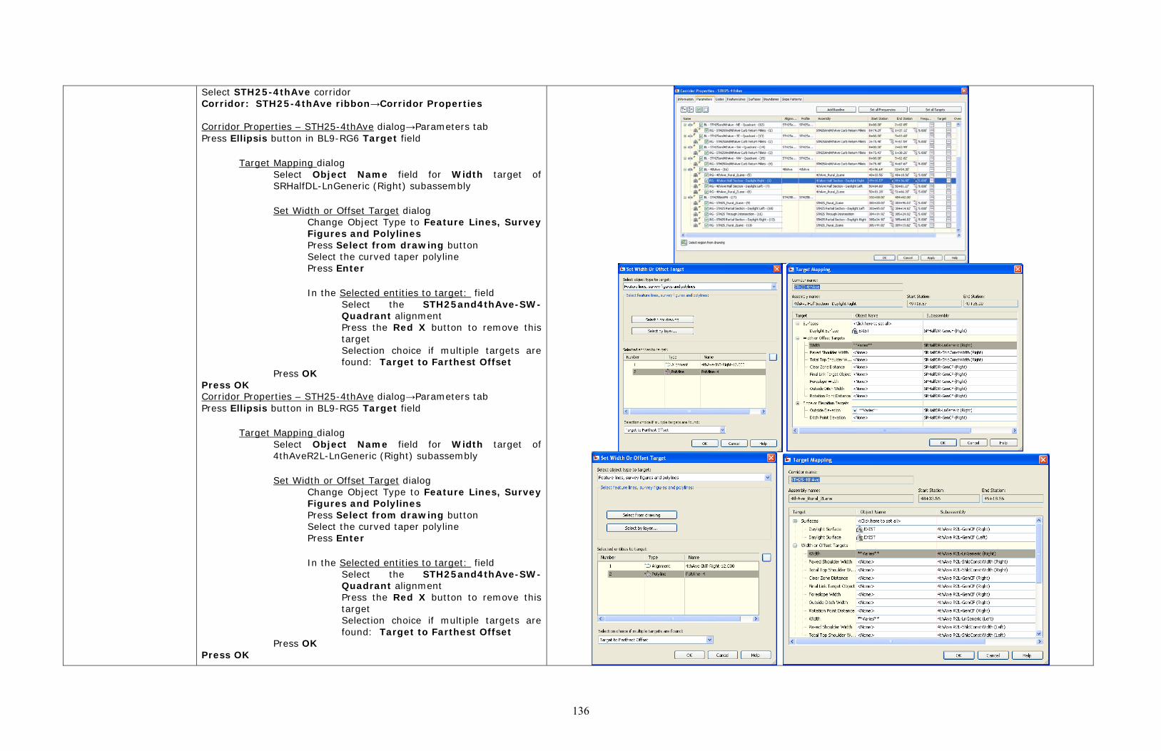
Select STH25-4thAve corridor Corridor: STH25-4thAve ribbon→Corridor Properties
Corridor Properties – STH25-4thAve dialog→Parameters tab Press Ellipsis button in BL9-RG6 Target field
Target Mapping dialog Select Object Name field for Width target of SRHalfDL-LnGeneric (Right) subassembly
Set Width or Offset Target dialog
Change Object Type to Feature Lines, Survey Figures and Polylines Press Select from drawing button Select the curved taper polyline Press Enter
In the Selected entities to target: field
Select the STH25and4thAve-SW-Quadrant alignment Press the Red X button to remove this target Selection choice if multiple targets are found: Target to Farthest Offset
Press OK Press OK Corridor Properties – STH25-4thAve dialog→Parameters tab Press Ellipsis button in BL9-RG5 Target field
Target Mapping dialog Select Object Name field for Width target of 4thAveR2L-LnGeneric (Right) subassembly
Set Width or Offset Target dialog
Change Object Type to Feature Lines, Survey Figures and Polylines Press Select from drawing button Select the curved taper polyline Press Enter
In the Selected entities to target: field
Select the STH25and4thAve-SW-Quadrant alignment Press the Red X button to remove this target Selection choice if multiple targets are found: Target to Farthest Offset
Press OK Press OK

137
Press OK Keyin LAYTHW, press Enter to thaw corridor layers C3D→Save
What happened? We just replaced all the straight-line tapers created by the intersection object with taper transitions that match the curve of the roadway. We used polylines to represent the new tapers, and adjusted corridor targets to hit taper polylines.
Before
After
138
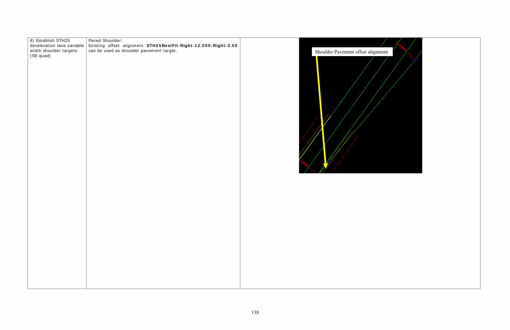
8) Establish STH25 deceleration lane variable width shoulder targets (SE quad)
Paved Shoulder: Existing offset alignment STH25BestFit-Right-12.000-Right-3.00 can be used as shoulder pavement target.
Shoulder Pavement offset alignment

139
Select STH25-4thAve corridor by picking a link at approximately station 382+00 Corridor: STH25-4thAve ribbon→Corridor Section Editor Section Editor ribbon→Parameter editor
Select a station: 380+20.03 STH25 R2L-ShldConstWidth (Right) Subassembly
Change Paved Shoulder Width to 0.001’ Press X to close Parameter Editor
Section Editor ribbon→Apply to a Station Range Start Station = 380+25 End Station = 383+95.03
Section Editor ribbon→Close Select STH25-4thAve corridor

140
Corridor: STH25-4thAve ribbon→Corridor Properties Corridor Properties – STH25-4thAve dialog→Parameters tab Press Ellipsis button in BL10-RG9 Target field
Target Mapping dialog Select Object Name field for Paved Shoulder Width target of STH26R2L-ShldConstWidth (Right) subassembly
Set Width or Offset Target dialog
Change Object Type to Alignments Select the STH25BestFit-Right-12.000-Right-3.00 alignment Press Add Press Enter
Press OK Press OK Press OK C3D→Save
What happened? We assigned the deceleration lane region of STH 25 a paved shoulder target of an offset alignment 15’ off the centerline, this lane represents edge of shoulder pavement in normal sections. We also changed the shoulder subassembly input value to create a 0.001’ wide shoulder pavement if the shoulder subassembly does not find the shoulder pavement alignment. When the deceleration lane taper starts, the shoulder subassembly attachment point follows the taper but the shoulder pavt edge stays at a 15’ offset. When the deceleration lane ends beyond a 15’ offset, no shoulder pavement is create by the subassembly.

141
CABC Shoulder: Select STH25-4thAve corridor Right-click→Isolate Objects→Hide Selected Objects Home ribbon→Layers→Layer Properties Layer Properties Manager
Select Roadway layer filter Make P_RDWY_ShldAgg the current layer Press X to close Layer Properties Manager
Home→Modify→Offset Specify offset distance
Key in 3 Press Enter
Select object to offset Pick the STH25-4thAve SE Quadrant curb return alignment
Specify point on side to offset Pick a point outside the deceleration lane (to the east of it)
Press Esc Select the new Shld Agg polyline Key in Pedit, Press Enter
Select Edit Vertex option Select next/previous until current vertex is at the point where deceleration lane meets the SE quad curb radius Select Break option Select Go Select Exit Press Esc
Select portion of polyline that is NE of the break (around curb radius and along 4th Ave Press Delete C3D→Open→Drawing
Select AliProfSTH25-Best-Fit.dwg for the AliProfs folder Press Open
(AliProfSTH25-BestFit.dwg is the active drawing) Select the STH25BestFit-Right-12.000-Right-10.000 alignment
Offset Alignment: STH25BestFit-Right-12.000-Right-10.000 ribbon→Alignment Properties
Alignment Properties→Masking tab Key in 38129.75 in the Start Station field Press OK
C3D→Save
Break polyline at this vertex
Delete this portion of polyline after break
142
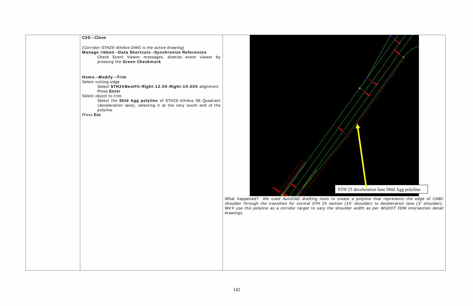
C3D→Close (Corridor-STH25-4thAve.DWG is the active drawing) Manage ribbon→Data Shortcuts→Synchronize References
Check Event Viewer messages, dismiss event viewer by pressing the Green Checkmark
Home→Modify→Trim Select cutting edge
Select STH25BestFit-Right-12.00-Right-10.000 alignment Press Enter
Select object to trim Select the Shld Agg polyline of STH25-4thAve SE Quadrant (deceleration lane), selecting it at the very south end of the polyline
Press Esc
What happened? We used AutoCAD drafting tools to create a polyline that represents the edge of CABC shoulder through the transition for normal STH 25 section (10’ shoulder) to deceleration lane (3’ shoulder). We’ll use this polyline as a corridor target to vary the shoulder width as per WisDOT FDM intersection detail drawings.
STH 25 deceleration lane Shld Agg polyline

143
Right-click→Isolate Objects→End Object Isolation Select STH25-4thAve corridor Corridor: STH25-4thAve ribbon→Corridor Properties
Corridor Properties – STH25-4thAve dialog→Parameters tab Press Ellipsis button in BL10-RG9 Target field
Target Mapping dialog Select Object Name field for Total Top Shoulder Width target of STH25 R2L-ShldConstWidth (Right) subassembly
Set Width or Offset Target dialog
Change Object Type to Feature Lines, Survey Figures and Polylines Press Select from drawing button Select the deceleration lane Shld Agg polyline Press Enter
Change Object Type to Alignments Select the STH25BestFit-Right-12.000-Right-10.00 alignment Press Add Selection choice if multiple targets are found: Target to Farthest Offset
Press OK Press OK Press OK C3D→Save

144
In the diagram to the right you can see how the Shoulder pavement width and the total shoulder width transition from 3’ and 10’ in the normal STH 25 section to 0’ and 3’ in the deceleration lane section. Modeling the shoulder width correctly is important to get the roadway subgrade width correct.
9) Repeat process (Step 8) of establishing deceleration/acceleration lane variable width shoulder targets for all acceleration and deceleration tapers in the corridor
Step 8 above documents a long sequence of AutoCAD based drawing commands to develop a polyline that represents the edge of shoulder for the northbound STH 25 deceleration lane. Understanding this documentation in this type of format is difficult because of the nature of the workflow, so instead of documenting the other 7 areas of the corridor that require this treatment I created a video to document the same processes.
Watch Fix Intersection Geometry Vbook for remainder of procedure!!!!!
Edge of Shoulder Pavt corridor feature line
Edge of CABC shoulder corridor feature line
Edge of STH 25 deceleration lane