ds435 opb ethernet media access controller (emac) · • supports reception of longer vlan type ......
TRANSCRIPT

0
OPB Ethernet Media Access Controller (EMAC) (v104a)
DS435 November 9 2005 0 0 Product Specification
IntroductionThis document provides the design specification for the 10100 Mbs Ethernet Media Access Controller (EMAC) The EMAC incorporates the applicable features described in IEEE Std 8023 MII interface specification The IEEE Std 8023 MII interface specification is referenced throughout this document and should be used as the authoritative specification Differences between IEEE Std 8023 MII interface specification and the Xilinx EMAC implementation are highlighted and explained in Specification Exceptions
Features
bull 32-bit OPB master and slave interfaces1
bull Memory mapped direct IO interface to registers and FIFOs as well as simple DMA and ScatterGather DMA
bull Data Realignment and Checksum offloading capabilities for higher system performance when C_DMA_PRESET=3
bull Media Independent Interface (MII) for connection to external 10100 Mbps PHY transceivers
- IEEE 8023-compliant MII
- Supports auto-negotiable and non auto-negotiable PHYs
- Supports 10BASE-T and 100BASE-TXFX IEEE 8023 compliant MII PHYs at full or half duplex
bull Independent internal 2K 4K 8K 16K or 32K byte TX and RX FIFOs for holding data for more than one packet (2K byte depth is sufficient for normal 1518 maximum byte packets but 4K byte depth provides better throughput 16K or 32K byte depth is required for Jumbo frames up to 9K bytes long)
LogiCOREtrade Facts
Core Specifics
Supported Device Family
QProtrade-R Virtex-IItrade QPro Virtex-II Spartan-IItrade
Spartan-IIE Spartan-3 Spartan-3E Virtex Virtex-II
Virtex-II Pro Virtex-4 Virtex-E
Version of Core opb_ethernet v104a
Resources Used
Min Max
Total Core IOs 181 181
Core FPGA IOBs 13 19
LUTs 1960 6157
FFs 1538 3198
Block RAMs 5 32
Provided with Core
Documentation Product Specification
Design File Formats NGC netlist VHDL wrapper
Constraints File NA
Verification NA
Instantiation Template NA
Reference Designs None
Design Tool Requirements
Xilinx Tools 81i or later
Verification NA
Simulation ModelSim SEEE 58d or later
Synthesis XST
Support
Support provided by Xilinx Inc
1 The master interface is only used if either simple or scatter gather DMA is included in the core at build time The core always includes a slave interface
Discontinued IP
DS435 November 9 2005 wwwxilinxcom 1Product Specification
copy 2005 Xilinx Inc All rights reserved All Xilinx trademarks registered trademarks patents and further disclaimers are as listed at httpwwwxilinxcomlegalhtm All other trademarks and registered trade-marks are the property of their respective owners All specifications are subject to change without noticeNOTICE OF DISCLAIMER Xilinx is providing this design code or information as is By providing the design code or information as one possible implementation of this feature application or standard Xil-inx makes no representation that this implementation is free from any claims of infringement You are responsible for obtaining any rights you may require for your implementation Xilinx expressly disclaims any warranty whatsoever with respect to the adequacy of the implementation including but not limited to any warranties or representations that this implementation is free from claims of infringement and any implied warranties of merchantability or fitness for a particular purpose
OPB Ethernet Media Access Controller (EMAC) (v104a)
2
D
Features (contd)
bull 16 32 or 64 entry deep FIFOs for the Transmit Length Receive Length and Transmit Status registers to support multiple packet operation
bull CSMACD compliant operation at 10 Mbps and 100 Mbps in half duplex mode
bull Programmable PHY reset signal
bull Internal loop-back capability
bull Optional support of jumbo frames up to 9K bytes in length
bull Supports unicast multicast and broadcast transmit and receive modes as well as promiscuous and 64 entry Contents Addressable Memory (CAM) based receive modes
bull Auto source address field insertion or overwrite or pass through for transmission
bull Auto pad field insertion on transmit
bull Auto Frame Check Sequence (FCS) field insertion or pass through on transmit
bull Auto pad and FCS field stripping or pass through on receive
bull Processes received pause packets
bull Supports reception of longer VLAN type frames
bull Supports MII management control writes and reads with MII PHYs
bull Programmable interframe gap
bull Provides counters and interrupts for many error conditions
bull Unaligned source and destination support
bull Checksum offloading support
Evaluation VersionThe EMAC LogiCORE is delivered with a hardware evaluation license When programmed into a Xilinx device the core will function in hardware for about 8 hours at the typical frequency of operation To use the EMAC LogiCORE without this timeout limitation a full license must be purchased
Functional DescriptionThe EMAC Interface design is a soft intellectual property (IP) core designed for implementation in several Xilinx FPGAs It supports the IEEE Std 8023 Media Independent Interface (MII) to industry standard Physical Layer (PHY) devices and communicates to a processor via an IBM On-Chip Peripheral Bus (OPB) interface The design provides a 10 Megabits per second (Mbps) and 100 Mbps (also known as Fast Ethernet) EMAC Interface This design includes many of the functions and the flexibility found in dedicated Ethernet controller devices currently on the market
The Xilinx EMAC design allows the customer to tailor the EMAC to suit their application by setting certain parameters to enabledisable features The parameterizable features of the design are discussed in EMAC Design Parameters
The EMAC is comprised of two IP blocks as shown in Figure 1 The IP Interface (IPIF) block is a subset of OPB bus interface features chosen from the full set of IPIF features to most efficiently couple the second block the EMAC core to the OPB processor bus for this packet1 based interface (this combined entity is referred to as a device) Although there are separate specifications for the IPIF design this specification addresses the specific implementation required for the EMAC design
iscontinued IP
wwwxilinxcom DS435 November 9 2005Product Specification
OPB Ethernet Media Access Controller (EMAC) (v104a)
DS435 NovProduct Sp
D
EMAC Endianess
The EMAC is designed as a big endian device (bit 0 is the most significant bit and is shown on the left of a group of bits) The 4-bit transmit and receive data interface to the external PHY is little endian (bit 3 is the most significant bit and appears on the left of the bus) The MII management interface to the PHY is serial with the most significant bit of a field being transmitted first
Figure 1 IPIF and EMAC Modules
Figure Top x-ref 1
ampSG
DMA MasterAttachment
SlaveAttachment
WritePacketFIFO
(2K 4K8K 16K
32K bytes)
ReadPacketFIFO
(2K 4K8K 16K
32K bytes)
FPGA Device
OP
B B
us (
32 b
its)
InterruptController
SWReset amp
MIR
OPB IPIF
OPB Ethernet
PHY_rx_clk
IOBRegisters
PHY_rx_data(30)
PHY_dv
PHY_rx_er
PHY_crsPHY_col
PHY_tx_clk
IOBRegisters
PHY_tx_data(30)
PHY_tx_en
PHY_tx_er
PHY_rx_en
PHY_rst_n
3-statebuf 1
3-statebuf 1
Notes 1 These buffers are automatically inserted by Platgen and are located in the opb_ethernet wrapper
PHY_mii_data
PHY_mii_clkPHY_Mii_clk_T
PHY_Mii_clk_O
PHY_Mii_data_T
PHY_Mii_data_O
PHY_Mii_data_I
MIImngmntcontrol
recv amploopback
AsyncFIFOs
TransmitAsyncFIFO
rece
ive
stat
em
achi
netr
ansm
it st
ate
mac
hine
half
dupl
exco
ntro
l
registers
errorcounters
length ampstatusFIFOs
(163264)
Receive Address Validation
CAM
SyncRegisters
OPB_Clk domain
ipif_emac_modules_blk_diagrameps
PH
Y_r
x_cl
k do
mai
nP
HY
_tx_
clk
dom
ain
PH
Y_m
ii_cl
k do
mai
n
Ethernet Protocol
Ethernet data is encapsulated in frames as shown in Figure 2 for standard Ethernet frames Figure 3 for VLAN frames Figure 4 for jumbo frames and Figure 5 for pauseflow control frames1 The fields in the frame are
1 IEEE Std 8023 uses the terms Frame and Packet interchangeably when referring to the Ethernet unit of transmission this specification does likewise
1 The EMAC design does not support the Ethernet 8-byte preamble frame type
iscontinued IP
ember 9 2005 wwwxilinxcom 3ecification
OPB Ethernet Media Access Controller (EMAC) (v104a)
4
D
transmitted from left to right The bits within the frame are transmitted from left to right (from least significant bit to most significant bit unless specified otherwise)
Preamble
The preamble field is used for synchronization and must contain seven bytes with the pattern 10101010 The pattern is transmitted from left to right If a collision is detected during the transmission of the preamble or start of frame delimiter fields the transmission of both fields will be completed For transmission this field is always automatically inserted by the EMAC and should never appear in the packet data provided to the EMAC For reception this field is always stripped from the packet data
Start Frame Delimiter
The start frame delimiter field marks the start of the frame and must contain the pattern 10101011 The pattern is transmitted from left to right If a collision is detected during the transmission of the preamble or start of frame delimiter fields the transmission of both fields will be completed The receive data valid signal from the PHY (RX_DV) may go active during the preamble but will be active prior to the start frame delimiter field For transmission this field is always automatically inserted by the EMAC and should never appear in the packet data provided to the EMAC For reception this field is always stripped from the packet data
Destination Address
The destination address field is 6 bytes in length1 The least significant bit of the destination address is used to determine if the address is an individualunicast (0) or groupmulticast (1) address Multicast addresses are used to group logically related stations The broadcast address (destination address field is all 1rsquos) is a multicast address that addresses all stations on the LAN The EMAC supports transmission and reception of unicast multicast and broadcast packets
Bits in the EMAC control register can be used to independently enable reception of unicast (destination address matches the station address in Station Address High (SAH) and Station Address Low (SAL) registers) multicast and broadcast frames An additional bit in the control register can be used to enable promiscuous mode which accepts all frames regardless of destination address This field is transmitted with the least significant bit first This field is always provided in the packet data for transmissions and is always retained in the receive packet data
Source Address
The source address field is 6 bytes in length2 This field is transmitted with the least significant bit first For transmission this field may be inserted automatically by the EMAC with information provided in the SAH and SAL registers or may be supplied as part of the packet data provided to the EMAC as indicated by a bit in the EMAC control register
When the source address is provided automatically by the EMAC a bit in the EMAC control register determines if the data in the SAH and SAL registers is inserted into the packet data in the transmit packet FIFO (ie no source address field exists in the transmit packet FIFO data) or if it overwrites a source address field provided in the transmit packet FIFO This field is always retained in the receive packet data
TypeLength
The typelength field is 2 bytes in length When used as a length field the value in this field represents the number of bytes in the following data field This value does not include any bytes that may have been inserted in the padding field following the data field The value of this field determines if it should be interpreted as a length as defined by the IEEE 8023 standard or a type field as defined by the Ethernet protocol
1 The EMAC design does not support 16-bit destination addresses as defined in the IEEE 802 standard2 The EMAC design does not support 16-bit source addresses as defined in the IEEE 802 standard
iscontinued IP
wwwxilinxcom DS435 November 9 2005Product Specification
OPB Ethernet Media Access Controller (EMAC) (v104a)
DS435 NovProduct Sp
D
The maximum length of a data field is 1500 bytes for normal (non-jumbo) frames Therefore a value in this field that exceeds 1500 (05DC hex) would indicates that a frame type rather than a length value is provided in this field The IEEE 8023 standard uses the value 1536 (0600 hex) or greater to signal a type field and that is what is used in the EMAC design Jumbo frames can have a data field as large as 8982 bytes
For reception if the field is a length field and jumbo frames are disabled the EMAC will compare the length against the actual data field length and will flag an error if they are different If the field is a type field or jumbo frames are enabled the EMAC will ignore the value and pass it along with the packet data with no further processing A typelength field value of 8100 hex indicates that the frame is a VLAN frame and a value of 8808 hex indicates a pause MAC control frame
If the frame is a VLAN type frame the EMAC must accept 4 additional bytes which are provided with the received packet data No additional processing is performed by the EMAC other than to process the additional bytes
The EMAC does not perform any processing of the typelength field on transmissions The data provided in the transmit packet is transmitted without any interpretation or validation
This field is transmitted with the least significant bit first but with the high order byte first This field is always provided in the packet data for transmissions and is always retained in the receive packet data
Data
The data field may vary from 0 to 1500 bytes in length for a normal frame and up to 8982 bytes for a jumbo frame This field is transmitted with the least significant bit first This field is always provided in the packet data for transmissions and is always retained in the receive packet data
Pad
The pad field may vary from 0 to 46 bytes in length This field is used to insure that the frame length is at least 64 bytes in length (the preamble and SFD fields are not considered part of the frame for this calculation) which is required for successful CSMACD operation The values in this field are used in the frame check sequence calculation but are not included in the length field value if it is used The length of this field and the data field combined must be at least 46 bytes If the data field contains 0 bytes the pad field will be 46 bytes If the data field is 46 bytes or more the pad field will have 0 bytes
For transmission this field may be inserted automatically by the EMAC or may be supplied as part of the packet data provided to the EMAC as indicated by a bit in the EMAC control register1
If EMAC insertion of padding is enabled in the EMAC control register the number of pad bytes to be inserted will determined by the transmit data length register and the FCS and Source address insertion enable bits in the EMAC control register resulting in the following formula
PAD (bytes) = 64 - [TXLengthReg + (ENFCS 4) + (ENSA 6)]
FCS
The FCS field is 4 bytes in length The value of the FCS field is calculated over the source address destination address lengthtype data and pad fields using a 32-bit Cyclic Redundancy Check (CRC) defined as2
G(x) = x32 + x26 + x23 + x22 + x16 + x12 + x11 + x10 + x8 + x7 + x5 + x4 + x2 + x1 + x0
1 If the pad field is inserted by the EMAC the FCS field will also be calculated and inserted by the EMAC This is necessary to insure proper FCS calculation over the pad field If the pad field is supplied as part of the transmit packet the FCS may be inserted by the EMAC or provided as part of the packet to the EMAC
2 Reference IEEE Std 8023 para 328
iscontinued IP
ember 9 2005 wwwxilinxcom 5ecification
OPB Ethernet Media Access Controller (EMAC) (v104a)
6
D
The CRC bits are placed in the FCS field with the x31 term in the left most bit of the first byte and the x0 term is the right most bit of the last byte (ie the bits of the CRC are transmitted in the order x31 x30 x1 x0) The EMAC implementation of the CRC algorithm calculates the CRC value a nibble at a time to coincide with the data size exchanged with the external PHY interface for each transmit and receive clock period
For transmission this field may be inserted automatically by the EMAC or may be supplied as part of the packet data provided to the EMAC as indicated by a bit in the EMAC control register
Figure 2 Ethernet Data Frame Format
Figure Top x-ref 2
PreambleStart of FrameDelimiter (SFD)
DestinationAddress
SourceAddress
TypeLength Data Pad Frame Check
Sequence
Number of Bytes7 1 6 6 2 0 - 1500 0 - 46 4
64 - 1518 Bytesethernet_data_frame_formateps
Figure 3 Ethernet VLAN Frame Format
Figure Top x-ref 3
Number of Bytes7 1 6 6 2 2 2 0 - 1500 0 - 46 4
68 - 1522 Bytes
ethernet_vlan_data_formateps
PreambleStart of FrameDelimiter (SFD)
DestinationAddress
SourceAddress
TypeLength
Data PadFrame Check
Sequence0X
8100VLAN
tag
Figure 4 Ethernet Jumbo Frame Format
Figure Top x-ref 4
PreambleStart of FrameDelimiter (SFD)
DestinationAddress
SourceAddress
TypeLength Data Pad Frame Check
Sequence
Number of Bytes7 1 6 6 2 1501 - 8982 0 - 46 4
1500 - 9000 Bytesethernet_jumbo_frame_formateps
Figure 5 Ethernet Pause Frame Format
Figure Top x-ref 5
Number of Bytes7 1 6 6 2 2 2 42 4
1519 - 9000 Bytes
ethernet_pause_frame_formateps
PreambleStart of FrameDelimiter (SFD)
DestinationAddress
SourceAddress
pauseperiod
ReservedFrame Check
Sequence8808 0001
iscontinued IP
wwwxilinxcom DS435 November 9 2005Product Specification
OPB Ethernet Media Access Controller (EMAC) (v104a)
DS435 NovProduct Sp
D
Interframe Gap1 and Deferring
Frames are transmitted over the serial interface with an interframe gap which is specified by the IEEE Std 8023 to be 96 bit times (96 uS for 10 MHz and 096 uS for 100 MHz) This is a minimum value and may be increased with a resulting decrease in throughput (results in a less aggressive approach to gaining access to a shared Ethernet bus) The process for deferring is different for half-duplex and full-duplex systems and is as follows
Half-Duplex
1 Even when it has nothing to transmit the EMAC monitors the bus for traffic by watching the carrier sense signal (CRS) from the external PHY Whenever the bus is busy (CRS =rsquo1rsquo) the EMAC defers to the passing frame by delaying any pending transmission of its own
2 After the last bit of the passing frame (when carrier sense signal changes from true to false) the EMAC starts the timing of the interframe gap
3 The EMAC will reset the interframe gap timer if carrier sense becomes true during the period defined by the interframe gap part 1 (IFG1) field of the IFGP register The IEEE std 8023 states that this should be the first 23 of the interframe gap timing interval (64 bit times) but may be shorter and as small as zero The purpose of this option is to support a possible brief failure of the carrier sense signal during a collision condition and is described in paragraph 42321 of the IEEE standard
4 The EMAC will not reset the interframe gap timer if carrier sense becomes true during the period defined by the interframe gap part 2 (IFG2) field of the IFGP register to ensure fair access to the bus The IEEE std 8023 states that this should be the last 13 of the interframe gap timing interval (32 bit times) but may be longer and as large as the whole interframe gap time
Full-Duplex
1 The EMAC does not use the carrier sense signal from the external PHY when in full duplex mode since the bus is not shared and only needs to monitor its own transmissions After the last bit of an EMAC transmission the EMAC starts the interframe gap timer and defers transmissions until it has reached the value represented by the combination of the IFG1 and IFG2 fields of the IFGP register
Carrier sense multiple access with collision detection (CSMACD) access method
A full duplex Ethernet bus is by definition a point to point dedicated connection between two Ethernet devices capable of simultaneous transmit and receive with no possibility of collisions
For a half duplex Ethernet bus the CSMACD media access method defines how two or more stations share a common bus
To transmit a station waits (defers) for a quiet period on the bus (no other station is transmitting (CRS =rsquo0rsquo)) and then starts transmission of its message after the interframe gap period If after initiating a transmission the message collides with the message of another station (COL -rsquo1rsquo) then each transmitting station intentionally continues to transmit (jam) for an additional predefined period (32 bit times for 10100 Mbs) to ensure propagation of the collision throughout the system
The station remains silent for a random amount of time (backoff) before attempting to transmit again
A station can experience a collision during the beginning of its transmission (the collision window) before its transmission has had time to propagate to all stations on the bus Once the collision window has passed a transmitting station has acquired the bus Subsequent collisions (late collisions) are avoided since all other (properly functioning) stations are assumed to have detected the transmission and are deferring to it
The time to acquire the bus is based on the round-trip propagation time of the bus (64 byte times for 10100 Mbs) In order to minimize processor bus transactions the EMAC design operating in half duplex mode will retain the
1 Interframe Gap and interframe spacing are used interchangeably and are equivalent
iscontinued IP
ember 9 2005 wwwxilinxcom 7ecification
OPB Ethernet Media Access Controller (EMAC) (v104a)
8
D
first 64 bytes of a transmission until the collision window has successfully passed If a collision does occur in the collision window the EMAC will retry the transmission without the need to re-acquire the packet data over the processor bus This is accomplished by using special FIFOs in the IPIF interface
Transmit Flow
The flow chart in Figure 6 shows the high level flow followed for packet transmission
Figure 6 Transmit Flow
Figure Top x-ref 6
StartTransmission
WaitBackoff
Time
SendJam
ComputeBackoff
StartTransmit
TransmitEnable
Half duplexamp Collision
TransmissionDone
TooMany
Attempts
Deferring
DoneTransmit OK
Done ExcessiveDeferral Error
Done Late Collision Error
IncrementRetry
AssembleFrame
F
F
F
F
F
LateCollision
F
T
T
T
T
T
transmit_flow
Receive Flow
The flow chart in Figure 7 shows the high level flow followed for packet reception
iscontinued IP
wwwxilinxcom DS435 November 9 2005Product Specification
OPB Ethernet Media Access Controller (EMAC) (v104a)
DS435 NovProduct Sp
D
Figure 7 Receive Flow
Figure Top x-ref 7
Startreceiving
Startreceive
Receiveenable
Donereceiving
DoneReceive OK
Donelength error
DisassembleFrame
F
Frame too small
Collision
F
F
F
T
T
T
T
Recognizeaddress
Frametoo long
ValidFCS
Extrabits
T
Validlengthtype
field
DoneFCS error
Done frametoo long error
Donealignment error
T
receive_flow
iscontinued IP
ember 9 2005 wwwxilinxcom 9ecification
OPB Ethernet Media Access Controller (EMAC) (v104a)
10
D
EMAC Design ParametersTo allow the user to generate an EMAC that is tailored for their system certain features are parameterizable in the EMAC design This allows the user to have a design that only utilizes the resources required by their system and runs at the best possible performance The features that are parameterizable in the Xilinx EMAC design are shown in Table 1
Table 1 EMAC Design Parameters
GenericFeature
DescriptionParameter Name Allowable Values
Default Value
VHDL Type
Top Level
G1 Device Block Id C_DEV_BLK_ID 0 - 255 1 integer
G2BUS clock period in pS
C_OPB_CLK_PERIOD_PS
Requirements as stated in note 1
10000 integer
G3 Device family C_FAMILY
virtex virtexe spartan2 spartan2e spartan3 qvirtex2 qrvirtex2 virtex2 virtex2p virtex4
virtex2 string
G4Device base address
C_BASEADDR See Note 2 FFFFFFFFstd logic vector
G5Device maximum address
C_HIGHADDR See Note 2 00000000std logic vector
G6MAC length and status FIFO depth
C_MAC_FIFO_DEPTH
16 32 64 64 integer
G7MAC length and status FIFO style
C_MAC_FIFO_BRAM_1_SRL_0
1 = use BRAMs0 = use SRL logic
0 integer
G8Include or exclude half duplex logic
C_HALF_DUPLEX_EXIST
1 = include half duplex logic0 = exclude half duplex logic
1 integer
G9Include or exclude jumbo frame support
C_JUMBO_EXIST
1 = support jumbo frames0 = do not support jumbo frames
0 integer
G10
Include or exclude CAM receive address validation logic
C_CAM_EXIST1 = include CAM logic0 = exclude CAM logic
0 integer
G11 CAM styleC_CAM_BRAM_0_SRL_1
1 = use SRL logic0 = use BRAMs
1 integer
OPBIPIF Interface
G12Module Identification Read
C_DEV_MIR_ENABLE
1 = MIR reads Exists0 = MIR reads Non-existent
1 integer
iscontinued IP
wwwxilinxcom DS435 November 9 2005Product Specification
OPB Ethernet Media Access Controller (EMAC) (v104a)
DS435 NovProduct Sp
D
G13
IPIF receiveread Packet FIFO depth in bits
C_IPIF_RDFIFO_DEPTH
262144(4) 131072 65536 32768 or 16384
32768 integer
G14IPIF transmitwrite Packet FIFO depth in bits
C_IPIF_WRFIFO_DEPTH
262144(4) 131072 65536 32768 or 16384
32768 integer
G15Software Reset Function
C_RESET_PRESENT
1 = software reset Exists0 = software reset Non-existent
1 integer
G16Interrupt device ID encoder
C_INCLUDE_DEV_PENCODER
1 = interrupt device ID encoder Exists0 = interrupt device ID encoder Non-existent
1 integer
G17 DMA Present C_DMA_PRESENT(3)
1 = no DMA function is required2 = simple 2 ch DMA is required3 = Scatter Gather DMA for packets is required
3 integer
G18DMA interrupt coalescing functionality
C_DMA_INTR_COALESCE
1 = DMA interrupt coalescing Exists0 = DMA interrupt coalescing Non-existent
1 integer
G19OPB address bus width (in bits)
C_OPB_AWIDTH 32 32 integer
G20OPB data bus width (in bits)
C_OPB_DWIDTH 32 32 integer
G21 Rx side DRE(5) C_RX_DRE_TYPE
0 = no DRE included1= DRE with Logic Mux2 = DRE with DSP48 Mux
0 integer
G22 Tx side DRE(5) C_TX_DRE_TYPE
0 = no DRE included1= DRE with Logic Mux2 = DRE with DSP48 Mux
0 integer
Table 1 EMAC Design Parameters (Contd)
GenericFeature
DescriptionParameter Name Allowable Values
Default Value
VHDL Type
iscontinued IP
ember 9 2005 wwwxilinxcom 11ecification
OPB Ethernet Media Access Controller (EMAC) (v104a)
12
D
Allowable Parameter Combinations
The EMAC is a synchronous design Due to the state machine control architecture of receive and transmit operations the OPB Clock must be greater than or equal to 65 MHz to allow Ethernet operation at 100 Mbs and greater than or equal to 65 Mhz for Ethernet operation at 10 Mbs
Detailed Parameter Descriptions
C_DEV_BLK_ID
The block ID is reflected as a field in the Module Identification Registers (MIR) This may be used for identification and verification of correct register access capability
C_OPB_CLK_PERIOD_PS
This clock period information is used by the IPIF sub-module for calculating the interrupt coalescing period Interrupt coalescing is optional and is only used when using Scatter Gather DMA
C_FAMILY
The family parameter is required to implement the core using family specific architecture features This parameter is automatically updated by the EDK tools based on the project target device information
C_BASEADDR and C_HIGHADDR
These values are used to generate the read and write enables for the FIFOs and registers and are byte addresses The address range defined by these parameters must be at least 0x4000 For example if the C_BASEADDR is set to 0x10000000 then C_HIGHADDR must be set to at least 0x10003FFF These parameters must be initialized since the default values have been selected so that they will generate an error during build if left unchanged
C_MAC_FIFO_DEPTH
This parameter is used to select a depth for the transmit status transmit length and receive length registers These registers are actually FIFOs and the depth represents the maximum number of entries that may be queued up before an overflow condition occurs
Selecting a larger depth will use more resources but offers the potential for higher bandwidth traffic on the Ethernet bus while reducing processor overhead The number of transmit and receive packets you will be able to
G23 Rx side CSUM(5) C_RX_INCLUDE_CSUM
0 = no CSUM support1 = CSUM support
0 integer
G24 Tx side CSUM(5) C_TX_INCLUDE_CSUM
0 = no CSUM support1 = CSUM support
0 integer
Notes 1 The OPB BUS clock frequency must be greater than or equal to 65 MHz for 100 Mbs Ethernet operation and
greater than or equal to 65 Mhz for 10 Mbs Ethernet operation2 The default value will insure that the actual value is set ie if the value is not set a compiler error will be
generated The address range must be at least 0x4000 (for example 0x10000000 and 0x10003FFF) 3 When C_DMA_PRESENT is rsquo2rsquo or rsquo3rsquo an OPB master interface is included in the core When
C_DMA_PRESENT is rsquo1rsquo no OPB master interface is used The OPB slave interface is always present4 The largest size of C_IPIF_FIFO_DEPTH is available for Virtex-II and Virtex-II Pro devices only5 DRE and CSUM are only available when C_DMA_PRESENT=3
Table 1 EMAC Design Parameters (Contd)
GenericFeature
DescriptionParameter Name Allowable Values
Default Value
VHDL Type
iscontinued IP
wwwxilinxcom DS435 November 9 2005Product Specification
OPB Ethernet Media Access Controller (EMAC) (v104a)
DS435 NovProduct Sp
D
queue up will be limited by the number of entries in these FIFOs or by the size of the packet FIFOs whichever fills up first
If the packet sizes will be small these FIFOs will fill up more quickly and should be as large as possible and conversely if the packet sizes are large the packet FIFOs will fill up first and should be as large as possible If the packet size is unknown or is distributed over all sizes than these FIFOs and the packet FIFOs should both be made as large as possible
C_MAC_FIFO_BRAM_1_SRL_0
This parameter is used to implement the status and length register FIFOs in either BRAM or in logic using SRL FIFOs This is strictly a trade off between logic and BRAM resource utilization and doesnrsquot affect performance appreciably although it may have an impact on place and route times depending on the fullness of the target device
C_HALF_DUPLEX_EXIST
This parameter controls the inclusion or exclusion of the special circuitry required for the core to operate in a half duplex environment The amount of resources used by this circuitry is significant and half duplex systems are not very common and becoming less so
When the half duplex circuitry is included selection of half duplex or full duplex mode is controlled by a bit in the EMAC control register When excluded the bit in the control register will be fixed to full duplex only regardless of the value written to that location
C_JUMBO_EXIST
This parameter modifies the core to allow the use of jumbo sized frames Normal frames are limited to a maximum of 1518 bytes Jumbo frames increases the frame size to a maximum of 9000 bytes Why 9000 Ethernet uses a 32 bit CRC that loses its effectiveness above about 12000 bytes Additionally 9000 is large enough to carry an 8 KB datagram a common size used for Network Files Storage (NFS) plus packet header overhead Since the opb_ethernet design is driven by powers of 2 the design is actually capable of processing packets up to 16383 bytes when jumbo frames are enabled
Jumbo frames is not part of the Ethernet standard and therefor is not supported by all Ethernet devices equally
In general increasing the size of the frame increases efficiency on the Ethernet bus and increases the theoretical maximum bandwidth of the Ethernet bus In an opb_ethernet system it also tends to reduce processor overhead
Enabling Jumbo frames with this parameter increases the size of some counters and the receive and transmit length register FIFOs This does increase resource usage and as a result should not be selected if jumbo frames will not be used
When jumbo frames are enabled with this parameter a bit in the EMAC control register further enables or disables the processing of receive jumbo frames Transmitting jumbo frames is always possible when this parameter is enabled
C_CAM_EXIST
This parameter include or excludes a Contents Addressable Memory (CAM) which can be used to store up to 64 MAC addresses for receive packet address validation Including this feature can significantly increase resource utilization Please refer to the section Receive Address Validation for more information on the functionality of this feature
iscontinued IP
ember 9 2005 wwwxilinxcom 13ecification
OPB Ethernet Media Access Controller (EMAC) (v104a)
14
D
C_CAM_BRAM_0_SRL_1
This parameter is used to implement the CAM in either BRAM or in logic using SRLs This is strictly a trade off between logic and BRAM resource utilization and doesnrsquot affect performance appreciably although it may have an impact on place and route times depending on the fullness of the target device
C_DEV_MIR_ENABLE
This parameter includes or excludes the Module Identification Registers in the IPIF sub module This includes the device MIR packet FIFO MIRs and the DMA MIR if the DMA module is included in the design The EMAC MIR is always included This will reduce resource utilization in those cases where the MIR functionality is not required
The software reset function (which shares an address with the Device MIR register) is not dependent on this parameter and may be present even when the MIR registers are not However the Device MIR register is dependent on the C_RESET_PRESENT parameter and will not be available if the software reset function is excluded from the design
C_IPIF_RDFIFO_DEPTH and C_IPIF_WRFIFO_DEPTH
These parameters set the depth (in bits) of the packet FIFOs The depth of the FIFOs impacts the number of BRAMS used in the system and only has a minor impact on logic resources used
Like the C_MAC_FIFO_DEPTH parameter a deeper packet FIFO will use more resources but offers the potential for higher bandwidth traffic on the Ethernet bus while reducing processor overhead
The minimum FIFO size (16384 bits = 2048 bytes) is large enough to hold one maximum normal frame of 1518 bytes However increasing the packet FIFO to hold at least two frames can significantly increase performance A minimum packet FIFO size of 131072 bits = 16384 bytes is required to hold one maximum size jumbo frame
In cases where packets are primarily small it may not be useful to have a large packet FIFO For example if all of the packets are 64 bytes a maximum depth (64 entry) length and status FIFO will limit queued packets to 4096 total bytes in the packet FIFO
Note that the largest size packet FIFOS (262144 bits = 32768 bytes) are only available in Virtex-II and newer devices (those devices with 18 Kb block RAMs)
C_RESET_PRESENT
The parameter includes or excludes the software reset function This may allow some reduction in resources if the software reset function is not required
The software reset function (which shares an address with the Device MIR register) is not dependent on the C_DEV_MIR_ENABLE parameter and may be present even when the MIR registers are not However the Device MIR register is dependent on the C_RESET_PRESENT parameter and will not be available if the software reset function is excluded from the design
C_INCLUDE_DEV_PENCODER
This parameter includes or excludes the Device Interrupt Identification Register This may allow some reduction in resources if the Device Interrupt Identification Register is not required
For more information about interrupts please read the following sections and refer to the Processor IP Reference Guide under Part 1 Embedded Processor IP under IPIF under OPB IPIF Architecture under OPB IPIF Interrupt for a complete description of the IPIF interrupt processing
iscontinued IP
wwwxilinxcom DS435 November 9 2005Product Specification
OPB Ethernet Media Access Controller (EMAC) (v104a)
DS435 NovProduct Sp
D
C_DMA_PRESENT
This parameter controls the inclusion of simple DMA (2) scatter gather DMA (3)or no DMA (1) functionality Choosing to include either DMA also automatically includes an OPB master bus interface
Including DMA can significantly increase resources but offers the potential for higher bandwidth traffic on the Ethernet bus while reducing processor overhead and increasing bandwidth on the processor bus
For more information about DMA please refer to the Processor IP Reference Guide under Part 1 Embedded Processor IP under IPIF under OPB IPIF Architecture under Direct Memory Access and Scatter Gather
C_DMA_INTR_COALESCE
This parameter includes or excludes the interrupt coalesce functionality This may allow some reduction in resources if the interrupt coalesce function is not required
Interrupt coalescing is only available when scatter gather DMA is being used and allows multiple interrupt events to queue up before being processed while guaranteeing a maximum wait bound This can reduce processor overhead by reducing the number of interrupts processed
For more information about interrupt coalescing and scatter gather DMA please read the following sections and refer to the Processor IP Reference Guide under Part 1 Embedded Processor IP under IPIF under OPB IPIF Architecture under Direct Memory Access and Scatter Gather
C_TX_DRE_TYPE and C_RX_DRE_TYPE
This parameter includes or excludes the Data Realignment Engine which allows unaligned source and desitination addresses originating from the DMA controller When this value is set to a (0) then there is no DRE functionality included When set to (1) then the DRE block is built entirely out of logic If the user wishes to save resources in exchange for DSP48s set this parameter to (2) and the muxing will be done via DSP48 blocks (2 DSP48s are consumed per TXRX) This feature is only available when C_DMA_PRESENT=3
C_TX_INCLUDE_CSUM and C_RX_INCLUDE_CSUM
This parameter includes or excludes the Checksum offloading blocks which assist software through hardware acceleration When this value is set to false then there is no CSUM capabilities included in the core and when this value is true and C_DMA_PRESENT=3 then the CSUM logic is included
C_OPB_AWIDTH and C_OPB_DWIDTH
These parameters should always be set to 32
C_MIIM_CLKDVD
C_SOURCE_ADDR_INSERT_EXIST
C_PAD_INSERT_EXIST
C_FCS_INSERT_EXIST
C_ERR_COUNT_EXIST
C_MII_EXIST
While these parameters are present in the design they should not be modified from their default values These features have not been fully tested with their secondary values and are also not supported by the software drivers
EMAC IO Signals
iscontinued IP
ember 9 2005 wwwxilinxcom 15ecification
OPB Ethernet Media Access Controller (EMAC) (v104a)
16
D
The external IO signals for the EMAC are listed in Table 2
Table 2 EMAC IO Signals
Generic Signal Name Interface IO Initial State Description
EMAC Signals
P1 PHY_rx_data(30)Ethernet
IOBI
Ethernet receive data Input from FPGA IO
P2 PHY_tx_data(30)Ethernet
IOBO 0000
Ethernet transmit data Output to FPGA IO
P3 PHY_dvEthernet
IOBI
Ethernet receive data valid Input from FPGA IO
P4 PHY_rx_erEthernet
IOBI
Ethernet receive error Input from FPGA IO
P5 PHY_tx_enEthernet
IOBO 0
Ethernet transmit enable Output to FPGA IO
P6 PHY_rx_enEthernet
IOB0 0
Ethernet receive enable controlled by control register bit 4 Output to FPGA IO
P7 PHY_tx_erEthernet
IOBO 0
Ethernet transmit error Output to FPGA IO
P8 PHY_tx_clkEthernet
IOBI
Ethernet transmit clock input from FPGA IO
P9 PHY_rx_clkEthernet
IOBI
Ethernet receive clock input from FPGA IO
P10 PHY_crsEthernet
IOBI
Ethernet carrier sense input from FPGA IO
P11 PHY_colEthernet
IOBI
Ethernet collision input from FPGA IO
P12 PHY_rst_nEthernet
IOBO 0
Ethernet PHY reset output to FPGA IO
P13 PHY_mii_clk_IEthernet
IOBI
MII management interface clock input to 3-state input buffer (not used)
P14 PHY_mii_clk_OEthernet
BufferO 0
MII management interface clock output to 3-state output buffer
P15 PHY_mii_clk_TEthernet
BufferO 0
MII management interface clock enable output to 3-state output buffer
P16 PHY_mii_data_IEthernet
BufferI
MII management interface data input from 3-state IO buffer
P17 PHY_mii_data_OEthernet
BufferO 0
MII management interface data output to 3-state IO buffer
iscontinued IP
wwwxilinxcom DS435 November 9 2005Product Specification
OPB Ethernet Media Access Controller (EMAC) (v104a)
DS435 NovProduct Sp
D
P18 PHY_mii_data_T
Ethernet Buffer
O 0MII management interface data enable output to 3-state IO buffer
OPB Signals
P19Sln_DBus(0C_OPB_DWIDTH-1)
OPB bus O 0EMAC slave output data bus
P20 Sln_xferAck OPB bus O 0EMAC slave transfer acknowledge
P21 Sln_Retry OPB bus O 0 EMAC slave retry
P22 Sln_ToutSup OPB bus O 0EMAC slave timeout suppress
P23 Sln_ErrAck OPB bus O 0EMAC slave error acknowledge
P24OPB_ABus(0C_OPB_AWIDTH-1)
OPB bus I OPB address bus
P25 OPB_BE(03) OPB bus I OPB byte enables
P26OPB_DBus(0C_OPB_DWIDTH-1)
OPB bus I OPB data bus
P27 OPB_RNW OPB bus IRead not Write (OR of all master RNW signals)
P28 OPB_select OPB bus IMaster has taken control of the bus (OR of all master selects)
P29 OPB_seqAddr OPB bus I OPB sequential address
P30 OPB_errAck OPB bus I OPB error acknowledge
P31 OPB_MnGrant OPB bus I OPB master bus grant
P32 OPB_retry OPB bus I OPB retry
P33 OPB_timeout OPB bus I OPB timeout error
P34 OPB_xferAck OPB bus IOPB transfer acknowledge
P35 Mn_request OPB bus O 0 EMAC master bus request
P36 Mn_busLock OPB bus O 0EMAC master bus arbitration lock
P37 Mn_select OPB bus O 0 EMAC master select
P38 Mn_RNW OPB bus O 0EMAC master Read not Write
P39 Mn_BE(03) OPB bus O 0EMAC master byte enables
P40 Mn_seqAddr OPB bus O 0EMAC master sequential address
Table 2 EMAC IO Signals (Contd)
Generic Signal Name Interface IO Initial State Description
iscontinued IP
ember 9 2005 wwwxilinxcom 17ecification
OPB Ethernet Media Access Controller (EMAC) (v104a)
18
D
EMAC Port DependenciesThe width of some of the EMAC signals depend on parameters selected in the design The dependencies between the EMAC design parameters and IO signals are shown in Table 3
Table 3 EMAC Parameter Port Dependencies
Generic Name Affects Depends Relationship Description
Design Parameters
G20 C_OPB_DWIDTH P18 P26 Specifies the Data Bus width
G19 C_OPB_AWIDTH P24 P41 Specifies the Address Bus width
G17 C_DMA_PRESENT G18 Specifies if DMA is present and which type
G18C_DMA_INTR_COASLESCE
G17Not used if scatter gather DMA not present (G17 is 0 1 2)
IO Signals
P19Sln_DBus(0C_OPB_DWIDTH-1)
G20 Width varies with the size of the Data bus
P24OPB_ABus(0C_OPB_AWIDTH-1)
G19 Width varies with the size of the Address bus
P26OPB_DBus(0C_OPB_DWIDTH-1)
G20 Width varies with the size of the Data bus
P41M_ABus(0C_OPB_AWIDTH-1)
G19 Width varies with the size of the Address bus
EMAC Interrupt InterfaceThe interrupt signals generated by the EMAC are provided as outputs as well as being managed by the Interrupt Source Controller in the EMAC IPIF module This interface provides many of the features commonly provided for interrupt handling Please refer to the Processor IP Reference Guide under Part 1 Embedded Processor IP under IPIF under OPB IPIF Architecture under OPB IPIF Interrupt for a complete description of the IPIF interrupt processing An overview diagram of the interrupt control structure is in Figure 8
P41Mn_ABus(0C_OPB_AWIDTH-1)
OPB bus O 0EMAC master address bus
System
P42 OPB_Clk System I System clock
P43 OPB_Rst System ISystem Reset (active high)
P44 IP2INTC_Irpt System O 0 System Interrupt
P45 Freeze System I System Freeze Input
P46 emac_intrpts(021) Genera Olsquo 0x0C0000 EMAC interrupts
Table 2 EMAC IO Signals (Contd)
Generic Signal Name Interface IO Initial State Description
iscontinued IP
wwwxilinxcom DS435 November 9 2005Product Specification
OPB Ethernet Media Access Controller (EMAC) (v104a)
DS435 NovProduct Sp
D
Figure 8 Interrupt Control Structure
Figure Top x-ref 8
Ethernet IP
IPIF0 1 2 3 4 5 6 7 8 9 10 11 12 13 14 15 16 17 18 19 20 21 22 23 24 25 26 27 28 29 30 31
Device Interrupt Enable Register (RW offset 0x0008)
Device Interrupt lsquoORrsquo
Device Interrupt Status Register (Read Only except bits 30 amp 31 offset 0x0000)
IP2Bus_Error_ sa
lsquoANDrsquo
Device Interrupt Pending Register (Read Only offset 0x0004)
Device Global InterruptEnable
(RW offset 0x001C)
Reserved (IPIF growth)
OPB Ethernet
DMASG
0 1 2 3 4 5 6 7
DMA CH2 (Rx)Interrupts
IPIF ISC
0 1 2 3 4 5 6 7
DMA CH1 (Tx)Interrupts
IPIF ISC
Ethernet Interrupts
IP ISC
0 1 2 3 4 5 6 7 21
WrFIFO RdFIFO
Priority Encoder ampInterrupt ID Register
(Read Only)(offset 0x0018)
ISCISCIPISR (RTOW offset 0x0020)
IPIER (RW offset 0x0028)
TXISR(RTOW offset 0x232C)
RXISR(RTOW offset 0x236C)
TXIER(RW offset 0x2330)
RXIER(RW offset 0x2370)
interrupt_example_etherneteps
The EMAC Interrupts values are available by reading the IP Interrupt status register (offset 0x0020) the interrupt values are shown in Figure 9 and described in Table 4
Figure 9 IPIF Interrupt Status Register (IPISR)
Figure Top x-ref 9
Reserved RAE RSE RFCS RMFE TPPR TLFO TSFO RSVD RERR RXCPRLFE
ipif_interrupt_control_registereps
RLE RLFE RCE RDFO TLFU TFSU RSVD TLFF TSFE TERR TXCP
10 11 12 13 14 15 16 17 18 19 20 21 23 2422 25 26 28 29 3027 31
iscontinued IP
ember 9 2005 wwwxilinxcom 19ecification
OPB Ethernet Media Access Controller (EMAC) (v104a)
20
D
Table 4 EMAC IP Interrupt Status Register Bit Definitions (offset 0x0020)
Bit Location
NameCore
AccessResetValue
Description
0 - 9 RSVD Read 0000000000 Unused
10 RAE ReadTOW rsquo0rsquo Receive Alignment Error interrupt
11 RLE ReadTOW rsquo0rsquo Receive Long Error interrupt
12 RSE ReadTOW rsquo0rsquo Receive Short Error interrupt
13 RLFE ReadTOW rsquo0rsquo Receive Length Field Error interrupt
14 RFCS ReadTOW rsquo0rsquo Receive FCS Error interrupt
15 RCE ReadTOW rsquo0rsquo Receive Collision Error interrupt
16 RMFE ReadTOW rsquo0rsquo Receive Missed Frame Error interrupt
17 RDFO ReadTOW rsquo0rsquo Receive Data FIFO Overrun interrupt
18 TPPR ReadTOW rsquo0rsquo Transmit Pause Packet Received interrupt
19 TLFU ReadTOW rsquo0rsquo Transmit Length FIFO Underrun interrupt
20 TLFO ReadTOW rsquo0rsquo Transmit Length FIFO Overrun interrupt
21 TSFU ReadTOW rsquo0rsquo Transmit Status FIFO Underrun interrupt
22 TSFO ReadTOW rsquo0rsquo Transmit Status FIFO Overrun interrupt
23 RSVD Read rsquo0rsquo Reserved
24 RSVD Read rsquo0rsquo Reserved
25 TLFF ReadTOW rsquo0rsquo Transmit Length FIFO Full interrupt
26 RLFE ReadTOW rsquo1rsquo Receive Length FIFO Empty interrupt
27 TSFE ReadTOW rsquo1rsquo Transmit Status FIFO Empty interrupt
28 RERR ReadTOW rsquo0rsquo Receive Error interrupt
29 TERR ReadTOW rsquo0rsquo Transmit error interrupt
30 RXCP ReadTOW rsquo0rsquo Receive complete interrupt
31 TXCP ReadTOW rsquo0rsquo Transmit complete interrupt
Detailed Interrupt Descriptions
Interrupt (data bus bit 31 emac_intrpts(0) ) -- Transmit complete interrupt
Indicates that at least one transmit has completed and that the transmit status word is available This interrupt is actually Transmit Status Register FIFO not empty This interrupt will stay set as long as at least one status word has not been read from the transmit status word register FIFO
Interrupt (data bus bit 30 emac_intrpts(1) ) -- Receive complete interrupt
Indicates that at least one successful receive has completed and that the receive status word packet data and packet data length is available This signal is not set for unsuccessful receives This interrupt is actually Receive Length Register FIFO not empty This interrupt will stay set as long as at least one length value has not been read from the receive length register FIFO
iscontinued IP
wwwxilinxcom DS435 November 9 2005Product Specification
OPB Ethernet Media Access Controller (EMAC) (v104a)
DS435 NovProduct Sp
D
Interrupt (data bus bit 29 emac_intrpts(2) ) -- Transmit error interrupt
Indicates that at least one failed transmit has completed and that the transmit status word is available This active high signal is one bus clock in width
Interrupt (data bus bit 28 emac_intrpts(3) ) -- Receive Error interrupt
Indicates that at least one failed receive has completed No receive status word packet data or packet data length is available since it is not retained for failed receives
Interrupt (data bus bit 27 emac_intrpts(4) ) -- Transmit Status FIFO Empty interrupt
This reflects the status of the transmit status FIFO empty flag It may be used to indicate that the status words for all completed transmissions have been processed Any other transmit packets already provided to the EMAC are either queued for transmit or are currently being transmitted but have not yet completed This active high signal remains active as long as the condition persists
Interrupt (data bus bit 26 emac_intrpts(5) ) --Receive Length FIFO Empty interrupt
This reflects the status of the receive length FIFO empty flag It may be used to indicate that the packet lengths for all successfully completed receives have been processed The status of this FIFO should always track the status of the receive status FIFO This active high signal remains active as long as the condition persists
Interrupt (data bus bit 25 emac_intrpts(6) ) -- Transmit Length FIFO Full interrupt
This reflects the status of the transmit length FIFO full flag It may be used to pause queueing of transmit packets until some of the queued packets have been processed by the EMAC This active high signal remains active as long as the condition persists
Interrupt (data bus bit 24 emac_intrpts(7) ) -- Reserved
Interrupt (data bus bit 23 emac_intrpts(8) ) -- Reserved
Interrupt (data bus bit 22 emac_intrpts(9) ) -- Transmit Status FIFO Overrun interrupt
Indicates that the Transmit status FIFO became full following the transmission of a packet and data was lost Care must be taken under these conditions to ensure that the transmit status words do not become out of sync with the originating packet information To insure that more data is not lost transmit status words stored in the FIFO should be processed to free up more locations Once set this bit can only be cleared with a reset
Interrupt (data bus bit 21 emac_intrpts(10) ) -- Transmit Status FIFO underrun interrupt
Indicates that an attempt was made to read the transmit status FIFO when it was empty and that the data received is not valid Once set this bit can only be cleared with a reset
Interrupt (data bus bit 20 emac_intrpts(11) ) -- Transmit Length FIFO Overrun interrupt
Indicates that more transmit packets were written to the EMAC transmit queue than the transmit length FIFO could store and data was lost This is non-recoverable condition since some or all of the packet data may have been stored in the transmit data FIFO and it can not be removed
Since there is not a transmit length entry for that packet the transmit length and data FIFOs are no longer synchronized This condition should be corrected by forcing an immediate reset of the transmit data FIFO and the transmit path in the EMAC Once set this bit can only be cleared with a reset
Interrupt (data bus bit 19 emac_intrpts(12) ) -- Transmit Length FIFO Underrun interrupt
Indicates that the EMAC attempted to remove an entry from the transmit length FIFO following the completion of a transmission and there were no entries in the FIFO This should never be possible and represents a serious
iscontinued IP
ember 9 2005 wwwxilinxcom 21ecification
OPB Ethernet Media Access Controller (EMAC) (v104a)
22
D
error This condition should be corrected by forcing an immediate reset of the transmit data FIFO and the transmit path in the EMAC condition Once set this bit can only be cleared with a reset
Interrupt (data bus bit 18 emac_intrpts(13) ) -- Transmit Pause Packet Received interrupt
Indicates that transmissions has paused as requested by a received pause packet
Interrupt (data bus bit 17 emac_intrpts(14) ) -- Receive Data FIFO Overrun interrupt
Indicates that the receive data FIFO became full during the reception of a packet and data was lost The EMAC will remove the partial packet from the receive data FIFO and no receive status or length will be stored but to insure that more data is not lost receive packets stored in the FIFO should be processed to free up more locations
Interrupt (data bus bit 16 emac_intrpts(15 ) ) -- Receive Missed Frame Error interrupt
Indicates that at least one frame addressed to the EMAC under the current address validation modes could not be received and the corresponding data was lost
Interrupt (data bus bit 15 emac_intrpts(16 ) ) -- Receive Collision Error interrupt
Indicates that at least one frame could not be received due to a collision and the corresponding data was lost
Interrupt (data bus bit 14 emac_intrpts(17) ) -- Receive FCS Error interrupt
Indicates that at least one frame addressed to the EMAC under the current address validation modes contained an FCS error and the corresponding data was discarded
Interrupt (data bus bit 13 emac_intrpts(18) ) -- Receive Length Field Error interrupt
Indicates that at least one frame addressed to the EMAC under the current address validation modes contained a length field which did not match the actual frame length and the corresponding data was discarded
Interrupt (data bus bit 12 emac_intrpts(19) ) -- Receive Short Error interrupt
Indicates that at least one frame addressed to the EMAC under the current address validation modes was shorter than allowed and the corresponding data was discarded
Interrupt (data bus bit 11 emac_intrpts(20) ) -- Receive Long Error interrupt
Indicates that at least one frame addressed to the EMAC under the current address validation modes was longer than allowed and the corresponding data was discarded
Interrupt (data bus bit 10 emac_intrpts(21) ) -- Receive Alignment Error interrupt
Indicates that at least one frame addressed to the EMAC under the current address validation modes was not integral number of bytes in length corresponding data was truncated to the last full byte
EMAC Register Definition
EMAC IPIF Registers
The EMAC design contains registers in each of the two modules (IPIF and EMAC core) The registers listed in Table 5 are contained in the IPIF module and are included for completeness of this specification Detailed descriptions of these registers are provided in the IPIF specifications listed in the Reference Documents section The presence of the DMA registers varies based on the setting of the C_DMA_PRESENT parameter The Device Interrupt Identification Register will not be present if the C_INCLUDE_DEV_PENCODER is set to rsquo0rsquo
The registers listed in Table 6 are contained in the EMAC core module and are described in detail in this specification The addresses for all registers are based on a parameter which is the base address for the entire EMAC module The address of each register is then calculated by an offset to the base address
iscontinued IP
wwwxilinxcom DS435 November 9 2005Product Specification
OPB Ethernet Media Access Controller (EMAC) (v104a)
DS435 NovProduct Sp
D
Table 5 EMAC IPIF Registers
Register Name OPB ADDRESS Access
Transmit DMA amp Scatter Gather Reset Register C_DEV_BASEADDR + 0x2300 Write
Transmit DMA amp Scatter Gather Module Identification Register
C_DEV_BASEADDR + 0x2300 Read
Transmit DMA amp Scatter Gather Control Register C_DEV_BASEADDR + 0x2304 ReadWrite
Transmit DMA amp Scatter Gather source address C_DEV_BASEADDR + 0x2308 ReadWrite
Transmit DMA amp Scatter Gather destination address
C_DEV_BASEADDR + 0x230C ReadWrite
Transmit DMA amp Scatter Gather startlength C_DEV_BASEADDR + 0x2310 ReadWrite
Transmit DMA amp Scatter Gather Status Register C_DEV_BASEADDR + 0x2314 Read
Transmit DMA amp Scatter Gather Buffer Descriptor Address
C_DEV_BASEADDR + 0x2318 ReadWrite
Transmit DMA Software Control Register C_DEV_BASEADDR + 0x231C ReadWrite
Transmit DMA amp Scatter Gather Unserviced Packet Count
C_DEV_BASEADDR + 0x2320 ReadWrite
Transmit DMA amp Scatter Gather Packet Count Threshold
C_DEV_BASEADDR + 0x2324 ReadWrite
Transmit DMA amp Scatter Gather Packet Wait Bound
C_DEV_BASEADDR + 0x2328 ReadWrite
Transmit DMA amp Scatter Gather Interrupt Status Register
C_DEV_BASEADDR + 0x232CReadToggle on
Write
Transmit DMA amp Scatter Gather Interrupt Enable Register
C_DEV_BASEADDR + 0x2330 ReadWrite
Receive DMA amp Scatter Gather Reset Register C_DEV_BASEADDR + 0x2340 Write
Receive DMA amp Scatter Gather Module Identification Register
C_DEV_BASEADDR + 0x2340 Read
Receive DMA amp Scatter Gather Control Register C_DEV_BASEADDR + 0x2344 ReadWrite
Receive DMA amp Scatter Gather source address C_DEV_BASEADDR + 0x2348 ReadWrite
Receive DMA amp Scatter Gather destination address
C_DEV_BASEADDR + 0x234C ReadWrite
Receive DMA amp Scatter Gather startlength C_DEV_BASEADDR + 0x2350 ReadWrite
Receive DMA amp Scatter Gather Status Register C_DEV_BASEADDR + 0x2354 Read
Receive DMA amp Scatter Gather Buffer Descriptor Address
C_DEV_BASEADDR + 0x2358 ReadWrite
Receive DMA Software Control Register C_DEV_BASEADDR + 0x235C ReadWrite
Receive DMA amp Scatter Gather Unserviced Packet Count
C_DEV_BASEADDR + 0x2360 ReadWrite
Receive DMA amp Scatter Gather Packet Count Threshold
C_DEV_BASEADDR + 0x2364 ReadWrite
iscontinued IP
ember 9 2005 wwwxilinxcom 23ecification
OPB Ethernet Media Access Controller (EMAC) (v104a)
24
D
EMAC Core Registers
The EMAC core registers are listed in Table 6
Receive DMA amp Scatter Gather Packet Wait Bound C_DEV_BASEADDR + 0x2368 ReadWrite
Receive DMA amp Scatter Gather Interrupt Status Register
C_DEV_BASEADDR + 0x236CReadToggle on
Write
Receive DMA amp Scatter Gather Interrupt Enable Register
C_DEV_BASEADDR + 0x2370 ReadWrite
Write Packet FIFO reset (write) Module Identification (read)
C_DEV_BASEADDR + 0x2000 ReadWrite
Write Packet FIFO Vacancy C_DEV_BASEADDR + 0x2004 Read
Write Packet FIFO Push C_DEV_BASEADDR + 0x2008 Write
Write Packet FIFO data write portC_DEV_BASEADDR + 0x2100 thru 0x28FF
Write
Read Packet FIFO reset (write) Module Identification (read)
C_DEV_BASEADDR + 0x2010 ReadWrite
Read Packet FIFO Occupancy C_DEV_BASEADDR + 0x2014 Read
Read Packet FIFO Pop C_DEV_BASEADDR + 0x2018 Write
Read Packet FIFO data read portC_DEV_BASEADDR + 0x2200 thru 0x29FF
Read
Device Interrupt Status Register C_DEV_BASEADDR + 0x0000 Read
Device Interrupt Pending Register C_DEV_BASEADDR + 0x0004 Read
Device Interrupt Enable Register C_DEV_BASEADDR + 0x0008 ReadWrite
Device Interrupt Identification Register C_DEV_BASEADDR + 0x0018 Read
Device Global Interrupt Enable C_DEV_BASEADDR + 0x001C ReadWrite
IP Interrupt Status Register C_DEV_BASEADDR + 0x0020ReadToggle on
Write
IP Interrupt Enable Register C_DEV_BASEADDR + 0x0028 ReadWrite
Device Software Reset (write) Module Identification (read) Register
C_DEV_BASEADDR + 0x0040 ReadWrite
Table 6 EMAC Core Registers
Register Name OPB ADDRESS Access
EMAC Module Identification Register (EMIR) C_DEV_BASEADDR + 0x1100 Read
EMAC Control Register (ECR) C_DEV_BASEADDR + 0x1104 ReadWrite
Interframe Gap Register (IFGP) C_DEV_BASEADDR + 0x1108 ReadWrite
Station Address High (SAH) C_DEV_BASEADDR + 0x110C ReadWrite
Station Address Low (SAL) C_DEV_BASEADDR + 0x1110 ReadWrite
Table 5 EMAC IPIF Registers (Contd)
Register Name OPB ADDRESS Access
iscontinued IP
wwwxilinxcom DS435 November 9 2005Product Specification
OPB Ethernet Media Access Controller (EMAC) (v104a)
DS435 NovProduct Sp
D
EMAC Module Identification Register (EMIR offset 0x1100)
The EMAC Version Register provides the software with a convenient method of verifying the Ethernet IP version and type
Figure 10 EMAC Module Identification Register (EMIR)
Figure Top x-ref 10
0 3 4 10 11 15 16 23 24 31
BLID
REVL
MNRV BTYP
emac_module_identification_registerepsMJRV
MII Management Control Register (MGTCR) C_DEV_BASEADDR + 0x1114 ReadWrite
MII Management Data Register (MGTDR) C_DEV_BASEADDR + 0x1118 ReadWrite
Receive Packet Length Register (RPLR) C_DEV_BASEADDR + 0x111C Read
Transmit Packet Length Register (TPLR) C_DEV_BASEADDR + 0x1120 ReadWrite
Transmit Status Register (TSR) C_DEV_BASEADDR + 0x1124 Read
Receive Missed Frame Count (RMFC) C_DEV_BASEADDR + 0x1128 Read
Receive Collision Count (RCC) C_DEV_BASEADDR + 0x112C Read
Receive FCS Error Count (RFCSEC) C_DEV_BASEADDR + 0x1130 Read
Receive Alignment Error Count (RAEC) C_DEV_BASEADDR + 0x1134 Read
Transmit Excess Deferral Count (TEDC) C_DEV_BASEADDR + 0x1138 Read
Receive Status Reg (RSR) C_DEV_BASEADDR + 0x113C Read
Receive CAM Entry High Reg (CAMH) C_DEV_BASEADDR + 0x1140 ReadWrite
Receive CAM Entry Low Reg (CAML) C_DEV_BASEADDR + 0x1144 ReadWrite
Table 7 EMAC Module Identification Register Bit Definitions
Bits NameCore
AccessResetValue
Description
0 - 3Major Version Number (MJRV)
ReadVersion ID0001 for this major version of 1
Module Major Version Number
4 - 10Minor Version Number (MNRV)
ReadVersion ID 0000010 for this minor version of 2
Module Minor Version Number
Table 6 EMAC Core Registers (Contd)
Register Name OPB ADDRESS Access
iscontinued IP
ember 9 2005 wwwxilinxcom 25ecification
OPB Ethernet Media Access Controller (EMAC) (v104a)
26
D
EMAC Control Register (ECR offset 0x1104)
The EMAC Control Register shown in Figure 11 and described in Table 8 controls the operation of the EMAC Please note that some of these bits should not be changed while transmit and receive are enabled (ECRENTX andor ECRENRX =rsquo1rsquo)
Figure 11 EMAC Control Register (ECR)
Figure Top x-ref 11
RSTTXRSTRX
ENPHYTXFCS
TXERR ILBE RSVD MA PA RXJB IPPE CAMW Reserved
emac_control_registerepsFD ENTX
ENRXTXPAD
TXSASAOE STRP UA BA REO CAME RSVD
0 1 2 3 4 5 6 7 8 9 10 11 12 13 14 15 16 17 18 19 20 21 23 2422 31
11 -15Rev Letter (REVL)
ReadVersion ID 00000 for this revision of a
Module Minor Version Letter This is a binary encoding of small case letters a through z (00000 - 11001)
16 - 23 Block ID (BLID) Read
Assigned by Platform Generator defaults to 00000001
Block ID Number Distinct number for each EMAC instantiated by Platform Generator
24 - 31Block Type (BTYP)
Read 00000001Block Type This is an 8 bit identifier unique to each IP type For EMAC this type is hex 01
Table 7 EMAC Module Identification Register Bit Definitions (Contd)
Bits NameCore
AccessResetValue
Description
iscontinued IP
wwwxilinxcom DS435 November 9 2005Product Specification
OPB Ethernet Media Access Controller (EMAC) (v104a)
DS435 NovProduct Sp
D
Table 8 EMAC Control Register Bit Definitions
Bit(s) NameCore
AccessResetValue
Description
0 FD ReadWrite rsquo0rsquo
Full Duplex Selects either full duplex mode (ie EMAC can receive and transmit simultaneously on a dedicated Ethernet bus segment) or half duplex mode Choosing half duplex enables CSMACD mode Choosing full duplex mode disables CCSMACD mode It is the responsibility of the software to ensure that this mode matches the PHY if the PHY is operating in auto-negotiation mode This bit should not be modified while transmit and receive are enabled ECRENTX andor ECRENRX =rsquo1rsquo
bull rsquo0rsquo -Half Duplex
bull rsquo1rsquo - Full Duplex
1 RSTTX ReadWrite rsquo1rsquo
Reset Transmitter Immediately resets the transmitter circuitry regardless of its current state The transmitter circuitry will remain in reset until this bit is set to rsquo0rsquo
bull rsquo0rsquo - Normal Operation
bull rsquo1rsquo - Reset
2 ENTX ReadWrite rsquo0rsquo
Enable Transmitter The transmitter circuitry will leave the idle state and begin transmission of a packet only when this bit is rsquo1rsquo and the transmit length register is not empty Setting this bit to rsquo0rsquo will cause the transmitter to enter the idle state after completion of any packet transmission in progress (graceful halt)
bull rsquo0rsquo - Disable Transmitter
bull rsquo1rsquo- Enable Transmitter
3 RSTRX ReadWrite rsquo1rsquo
Reset Receiver Immediately resets the receiver circuitry regardless of its current state The receiver circuitry will remain in reset until this bit is set to rsquo0rsquo
bull rsquo0rsquo - Normal Operation
bull rsquo1rsquo - Reset
4 ENRX ReadWrite rsquo0rsquo
Enable Receiver The receiver circuitry will leave the idle state and begin monitoring the Ethernet bus only when this bit is rsquo1rsquo Setting this bit to rsquo0rsquo will cause the receiver to enter the idle state after completion of any packet reception in progress (graceful halt) This bit also controls the output signal PHY_rx_en
bull rsquo0rsquo - Disable Receiver
bull rsquo1rsquo- Enable Receiver
iscontinued IP
ember 9 2005 wwwxilinxcom 27ecification
OPB Ethernet Media Access Controller (EMAC) (v104a)
28
D
5 ENPHY ReadWrite rsquo1rsquo
Enable PHY This value of this bit is driven to the PHY interface PHY_rst_n signal If the external PHY supports this signal and this bit is rsquo0rsquo the PHY will reset and remain in reset until this bit is set to rsquo1rsquo PHY_rst_n will also be driven active while OPB_Rst is active regardless of value of this bit PHY_rst_n can also be driven active by writing to the Device Software Reset Register if the software reset function has been included in the build The software reset function is not dependent on the value of this bit
bull rsquo0rsquo - Disable Reset PHY
bull rsquo1rsquo- Enable PHY
6 TXPAD ReadWrite rsquo1rsquo
Enable Transmit Auto Pad Insertion Enables automatic pad field insertion by the EMAC circuitry if it is necessary When this is enabled the transmit packet data provided to the EMAC should not contain pad data When this is enabled auto FCS insertion must also be selected to insure correct FCS calculation over the pad field When this is disabled the transmit packet data provided to the EMAC should contain pad data if required This bit should not be modified while transmit and receive are enabled ECRENTX =rsquo1rsquo andor ECRENRX =rsquo1rsquo
bull rsquo0rsquo - Disable Auto Pad Insertion
bull rsquo1rsquo- Enable Auto Pad Insertion
7 TXFCS ReadWrite rsquo1rsquo
Enable Transmit Auto FCS Insertion Enables automatic FCS field insertion by the EMAC circuitry When this is enabled the transmit packet data provided to the EMAC should not contain FCS data When this is disabled the transmit packet data provided to the EMAC should contain FCS data This bit should not be modified while transmit and receive are enabled ECRENTX =rsquo1rsquo andor ECRENRX =rsquo1rsquo
bull rsquo0rsquo - Disable Auto FCS Insertion
bull rsquo1rsquo- Enable Auto FCS Insertion
8 TXSA ReadWrite rsquo1rsquo
Enable Transmit Auto Source Address Insertion Enables automatic source address field insertion from the Station Address Registers by the EMAC circuitry When this is enabled the transmit packet data provided to the EMAC should not contain source address data When this is disabled the transmit packet data provided to the EMAC should contain source address data This bit should not be modified while transmit and receive are enabled ECRENTX =rsquo1rsquo andor ECRENRX =rsquo1rsquo
bull rsquo0rsquo - Disable Auto Source Address Insertion
bull rsquo1rsquo- Enable Auto Source Address Insertion
Table 8 EMAC Control Register Bit Definitions (Contd)
Bit(s) NameCore
AccessResetValue
Description
iscontinued IP
wwwxilinxcom DS435 November 9 2005Product Specification
OPB Ethernet Media Access Controller (EMAC) (v104a)
DS435 NovProduct Sp
D
9 TXERR ReadWrite rsquo0rsquo
Transmit Error Insertion The value of this bit is driven to the PHY interface TX_ER signal If the external PHY supports this mode it will inject an error encoded byte into the transmit data when operating in 100 Base-T mode The PHY will ignore this input when operating in 10Base-T mode This bit should not be modified while transmit and receive are enabled ECRENTX =rsquo1rsquo andor ECRENRX =rsquo1rsquo
bull rsquo0rsquo - Disable Error Insertion
bull rsquo1rsquo - Enable Error Insertion
10 SAOE ReadWrite rsquo1rsquo
Source Address Overwrite Enable When set to rsquo1rsquo it enables overwriting of the source address field provided in the packet data to be transmitted The source address field is overwritten with the value contained in the SAH and SAL registers When set to rsquo0rsquo the source address field is not included in the packet data to be transmitted and the value contained in the SAH and SAL registers is inserted into the packet data stream This bit is only used when auto source address insertion is enabled ECRTXSA =rsquo1rsquo
11 ILBE ReadWrite rsquo0rsquo
Internal Loop-Back Enable Enables looping of the transmit data directly to the receive data path internally to the EMAC The transmit and receive paths are isolated from the external PHY
12 STRP ReadWrite rsquo0rsquo
Pad amp FCS Strip Enable Enables stripping of receive pad and FCS fields when typelength field is a length
bull rsquo0rsquo - Disable Strip
bull rsquo1rsquo - Enable Strip
13 Reserved Read rsquo0rsquo bull Reserved This bit is reserved for future use
14 UA ReadWrite rsquo1rsquo
Enable Unicast Address Enables the EMAC to accept valid frames that have a destination address field that matches the value in the station address registers This bit should not be modified while transmit and receive are enabled ECRENTX =rsquo1rsquo andor ECRENRX =rsquo1rsquorsquo
bull rsquo0rsquo - Disable Unicast Address
bull rsquo1rsquo - Enable Unicast Address
15 MA ReadWrite rsquo0rsquo
Enable Multicast Address Enables the EMAC to accept valid frames that have a multicast (excluding broadcast) destination address field This bit should not be modified while transmit and receive are enabled ECRENTX =rsquo1rsquo andor ECRENRX =rsquo1rsquorsquo
bull rsquo0rsquo - Disable Multicast Address
bull rsquo1rsquo - Enable Multicast Address
Table 8 EMAC Control Register Bit Definitions (Contd)
Bit(s) NameCore
AccessResetValue
Description
iscontinued IP
ember 9 2005 wwwxilinxcom 29ecification
OPB Ethernet Media Access Controller (EMAC) (v104a)
30
D
16 BA ReadWrite rsquo1rsquo
Enable Broadcast Address Enables the EMAC to accept valid frames that have a broadcast destination address field This bit should not be modified while transmit and receive are enabled ECRENTX =rsquo1rsquo andor ECRENRX =rsquo1rsquo
bull rsquo0rsquo - Disable Broadcast Address
bull rsquo1rsquo - Enable Broadcast Address
17 PA ReadWrite rsquo0rsquo
Enable Promiscuous Address Mode Enables the EMAC to accept valid frames This bit should not be modified while transmit and receive are enabled ECRENTX =rsquo1rsquo andor ECRENRX =rsquo1rsquo
bull rsquo0rsquo - Disable Promiscuous Address Mode
bull rsquo1rsquo - Enable Promiscuous Address Mode
18 REO ReadWrite rsquo0rsquo
Receive Error Override Enables the EMAC to attempt to receive and store frames even if they contain errors
bull rsquo0rsquo - Disable Error Override
bull rsquo1rsquo - Enable Error Override
19 RXJB ReadWrite 0
Receive Jumbo Frames Enable Enables the EMAC to receive jumbo size frames This bit can not be set if the jumbo functionality was not included using the parameter C_JUMBO_EXIST
bull rsquo0rsquo - Disable Rx Jumbo Frames
bull rsquo1rsquo - Enable Rx Jumbo Frames
20 CAME ReadWrite 0
Receive CAM Enable Enables the EMAC to use the 64 entry CAM for receive address validation This bit can not be set if the CAM was not included using the parameter C_CAM_EXIST
bull rsquo0rsquo - Disable Rx CAM
bull rsquo1rsquo - Enable Rx CAM
21 IPPE ReadWrite rsquo0rsquo
Interpret Pause Packets Enables the EMAC to process valid received pause packets
bull rsquo0rsquo - Disable Pause Packets
bull rsquo1rsquo - Enable Pause Packets
22 Reserved Read rsquo0rsquo Reserved These bits are reserved for future use
23 CAMW ReadWrite rsquo0rsquo
Receive CAM Write This bit Writes the contents of the CAMH and CAML registers into the CAM address also provided in CAMH This bit will automatically reset to rsquo0rsquo Setting this bit will have no effect if the CAM was not included using the parameter C_CAM_EXIST
bull rsquo0rsquo - CAM Write Idle
bull rsquo1rsquo - Initiate a CAM Write
24-31 Reserved Read 0x000 Reserved These bits are reserved for future use
Table 8 EMAC Control Register Bit Definitions (Contd)
Bit(s) NameCore
AccessResetValue
Description
iscontinued IP
wwwxilinxcom DS435 November 9 2005Product Specification
OPB Ethernet Media Access Controller (EMAC) (v104a)
DS435 NovProduct Sp
D
Interframe Gap Register (IFGP offset 0x1108)
The Interframe Gap Register shown in Figure 12 and described in Table 9 controls the duration of the interframe Gap The Interframe Gap is the sum of IFGP1 and IFGP2 measuring in units of the bit time multiplied by four Please refer to the paragraph Interframe Gap and Deferring for information about how the Interframe Gap is used by the EMAC Please note that these settings should not be changed while transmit and receive are enabled (ECRENTX andor ECRENRX =rsquo1rsquo)
Figure 12 Interframe Gap Register (IFGP)
Figure Top x-ref 12
0 4 5 9 10
IFGP2
interframe_gap_registerepsIFGP1 Reserved
Table 9 Interframe Gap Register Bit Definitions
Bit(s) NameCore
AccessResetValue
Description
0-4 IFGP1 ReadWrite 10000
Interframe Gap Part 1 A value of 1 in this field would provide a 4 bit time interframe part 1 gap to be combined with the interframe part 2 gap for the total interframe gap time The reset value for this field is value recommended for most operation by IEEE Std 8023 This field should not be modified while transmit and receive are enabled ECRENTX =rsquo1rsquo andor ECRENRX =rsquo1rsquo
5-9 IFGP2 ReadWrite 01000
Interframe Gap Part 2 A value of 1 in this field would provide a 4 bit time interframe part 2 gap to be combined with the interframe part 1 gap for the total interframe gap time The reset value for this field is value recommended for most operation by IEEE Std 8023 This field should not be modified while transmit and receive are enabled ECRENTX =rsquo1rsquo andor ECRENRX =rsquo1rsquo
10-31 Reserved Read 0x000000 Reserved These bits are reserved for future use
Receive Packet Length Register (RPLR offset 0x111C)
The receive packet length register is actually a FIFO of register values each corresponding to a valid frame received The data for the frame is stored in the receive data FIFO and the status word is stored in the receive status register FIFO
The width of this register varies based on the value of the parameter C_JUMBO_EXIST If C_JUMBO_EXIST = rsquo1rsquo bits 18 through 31 are used to store the length value where as bits 21 through 31 are used when C_JUMBO_EXIST = rsquo0rsquo
iscontinued IP
ember 9 2005 wwwxilinxcom 31ecification
OPB Ethernet Media Access Controller (EMAC) (v104a)
32
D
The data is written by the EMAC when the framersquos destination address passes the current address validation modes and when the frame has been determined to be valid and the receive data FIFO had enough locations that all of the frame data has been saved The existence of data in the receive packet length FIFO (FIFO empty flag is rsquo0rsquo) may be used to initiate the processing of received packets until this FIFO is empty The interrupt Receive Complete is set when at least one entry is stored in this FIFO from a successful packet reception An interrupt Receive Length FIFO Empty also is available Reading this register causes the current value to be removed from the FIFO The Receive Packet Length register is shown in Figure 13 and described in Table 10
Reading of this register will Flush the RX_DRE of any residue data if C_RX_DRE_TYPEgt0
Figure 13 Receive Packet Length Register (RPLR)
Figure Top x-ref 13
18 19 20 21 31
Reserved RXPL
receive_packet_length_registereps
Table 10 Receive Packet Length Register Bit Definitions
Bit(s) NameCore
AccessResetValue
Description
0-17 or
0-20Reserved Read 0x00000 Reserved These bits are reserved for future use
18-31 or
21-31RXPL Read 0x000
Receive Packet Length The number of bytes of the corresponding receive packet stored in the receive data FIFO
Transmit Packet Length Register (TPLR offset 0x1120)
The transmit packet length register is actually a FIFO of register values each corresponding to a valid frame ready for transmit The data for the frame is stored in the transmit data FIFO
The width of this register varies based on the value of the parameter C_JUMBO_EXIST If C_JUMBO_EXIST = rsquo1rsquo bits 18 through 31 are used to store the length value where as bits 21 through 31 are used when C_JUMBO_EXIST = rsquo0rsquo
The data is written to the EMAC over the external processor bus interface either by simple DMA ScatterGather DMA or by direct memory mapped access
When presenting a transmit packet to the EMAC the packet data should first be written to the transmit data FIFO The existence of data in the transmit packet length FIFO (FIFO empty flag is rsquo0rsquo) is used by the EMAC to initiate the processing of transmit packets until this FIFO is empty
The Transmit Packet Length register shown in Figure 14 and described in Table 11 can be read over the processor interface but only the EMAC can remove a value from the FIFO The EMAC will remove the current length from the FIFO when it completes the corresponding transmission If multiple reads are performed prior to that completion the same value will be returned for each read operation
iscontinued IP
wwwxilinxcom DS435 November 9 2005Product Specification
OPB Ethernet Media Access Controller (EMAC) (v104a)
DS435 NovProduct Sp
D
Writing to this register will cause an automatic Write Push to happen on the Write Packet FIFO if C_TX_DRE_TYPEgt0
Figure 14 Transmit Packet Length Register (TPLR)
Figure Top x-ref 14
18 19 20 21 31
Reserved TXPL
transmit_packet_length_registereps
Table 11 Transmit Packet Length Register Bit Definitions
Bit(s) NameCore
AccessResetValue
Description
0-17or
0-20Reserved Read 0x00000 Reserved These bits are reserved for future use
18-31 or
21-31TXPL ReadWrite 0x000
Transmit Packet Length The number of bytes of the corresponding transmit packet stored in the transmit data FIFO
Receive Status Register (RSR offset 0x113C)
The receive status register shown in Figure 15 and described in Table 12 is a place holder for the receive status register that is used by the Scatter Gather DMA interface The EMAC does not need a receive status register but is required to provide the correct value in bit 31 to the generalized Scatter Gather DMA circuitry as part of a standard receive packet operation
Note that when C_RX_INCLUDE_CSUM is true this value is written into the RDPFIFO along with the RAW checksum
Figure 15 Receive Status Register (RSR)
Figure Top x-ref 15
31
Reserved RPCF
receive_status_registereps
iscontinued IP
ember 9 2005 wwwxilinxcom 33ecification
OPB Ethernet Media Access Controller (EMAC) (v104a)
34
D
Table 12 Receive Status Register Bit Definitions
Bit(s) NameCore
AccessResetValue
Description
0 - 30 Reserved NA 0x00000000Reserved These bits are unused and will always return all zeros
31 RPCF Read rsquo1rsquo
Receive Packet Complete Flag This bit is always rsquo1rsquo and is used to indicate to the software that a buffer descriptor associated with this packet has been completely processed by the DMA circuitry and is available for software use
Transmit Status Register (TSR offset 0x1124)
The transmit status register shown in Figure 16 and described in Table 13 is actually a FIFO of register values each corresponding to a frame transmission attempt The bits in this register reflect the specific status of the corresponding transmit operation including the EMAC settings which were applied to the transmit operation Reading this register causes the current value to be removed from the FIFO
Figure 16 Transmit Status Register (TSR)
Figure Top x-ref 16
0 1 2 6 7 8 31
TXED TXA Reserved TPCF
transmit_status_registerepsRFIFOU TXLC
iscontinued IP
wwwxilinxcom DS435 November 9 2005Product Specification
OPB Ethernet Media Access Controller (EMAC) (v104a)
DS435 NovProduct Sp
D
Table 13 Transmit Status Register Bit Definitions
Bit(s) NameCore
AccessReset Value Description
0 TXED Read rsquo0rsquo
Transmit Excess Deferral Error This bit is only applicable in half-duplex mode It indicates that at least one transmit frame was not able to complete transmission due to collisions that exceed the maximum number of retries (16) This bit is cleared to rsquo0rsquo when read
bull rsquo0rsquo - No excess deferrals occurred since the last read
bull rsquo1rsquo - At least one excess deferral has occurred
1 PFIFOU Read rsquo0rsquo
Packet Fifo Underrun This bit indicates that at least one transmit frame experienced a packet FIFO underrun condition during transmission This bit is cleared to rsquo0rsquo when read
bull rsquo0rsquo - No packet FIFO underruns occurred since the last read
rsquo1rsquo - At least one packet FIFO underrun has occurred
2- 6 TXA Read 0x00
Transmission Attempts The number of transmission attempts made There will be a maximum of 16 attempts
7 TXLC Read rsquo0rsquo
Transmit Late Collision Error This bit is only applicable in half-duplex mode It indicates a non-recoverable collision occurred more than 64-bit times after the start of the transmission No automatic retransmission can be attempted by the EMAC A late collision should never occur on a compliant Ethernet network
bull rsquo0rsquo - No late collisions occurred
bull rsquo1rsquo - Late collision occurred
8 - 30 Reserved NA 0x000000Reserved These bits are unused and will always return all zeros
31 TPCF Read rsquo1rsquo
Transmit Packet Complete Flag This bit is always rsquo1rsquo and is used to indicate to the software that a buffer descriptor associated with this packet has been completely processed by the DMA circuitry and is available for software use
Station Address High Register (SAH offset 0x110C)
The station address high register shown inFigure 17 and described in Table 14 contains the high-order 16 bits of the 48 bit station address
iscontinued IP
ember 9 2005 wwwxilinxcom 35ecification
OPB Ethernet Media Access Controller (EMAC) (v104a)
36
D
Figure 17 Station Address High (SEH) Register
Figure Top x-ref 17
16 31
Reserved SAH
station_address_high_registereps
Table 14 Station Address High Register Bit Definitions
Bit(s) NameCore
AccessResetValue
Description
0-15 Reserved Read 0x0000 Reserved These bits are reserved for future use
16-31 SAH ReadWrite 0x0000Station Address High This register should not be modified while transmit and receive are enabled ECRENTX =rsquo1rsquo andor ECRENRX =rsquo1rsquo
Station Address Low Register (SAL offset 0x1110)
The station address low register shown inFigure 18 and described in Table 15 contains the low-order 32 bits of the 48 bit station address
Figure 18 Station Address Low (SAL) Register
Figure Top x-ref 18
310
SAL
station_address_low_registereps
Table 15 Station Address Low Register Bit Definitions
Bit(s) NameCore
AccessResetValue
Description
0-31 D0 - D31 ReadWrite 0x00000000
Station Address Low This register should not be modified while transmit and receive are enabled ECRENTX =rsquo1rsquo andor ECRENRX =rsquo1rsquorsquo
MII Management Control Register (MGTCR offset 0x1114)
The MII management control register shown in Figure 19 and described in Table 16 is used with the MII management data register to perform read and writes between the EMAC and the external PHY device via the MII management interface
iscontinued IP
wwwxilinxcom DS435 November 9 2005Product Specification
OPB Ethernet Media Access Controller (EMAC) (v104a)
DS435 NovProduct Sp
D
Figure 19 MII Management Control Register (MGTCR)
Figure Top x-ref 19
mii_mngmnt_control_registereps
0 1 2 6 7 11 12 13 14
SB IEPHYAD
RWN REGAD MIIRE
Reserved
Table 16 MII Management Control Register Bit Definitions
Bit(s) NameCore
AccessResetValue
Description
0 SB ReadWrite rsquo0rsquo
Start Busy writing a rsquo1rsquo to this bit initiates an MII read or write operation The EMAC will clear this bit to rsquo0rsquo when the operation has been completed
bull rsquo0rsquo - No MII Operation in Progress
bull rsquo1rsquo- MII Read or Write in Progress
1 RWN ReadWrite rsquo1rsquo
Read Write Not This bit indicates the direction of the MII operation
bull rsquo0rsquo - Write to PHY register
bull rsquo1rsquo- Read from PHY register
2-6 PHYAD ReadWrite 0x00PHY Address This field is used to specify the address of the PHY to be accessed
7-11 REGAD ReadWrite 0x00Register Address This field is used to specify the register in the PHY to be accessed
12 IE ReadWrite rsquo0rsquo
MII Management Interface Enable This bit controls the 3-state drivers for the MII management signal interface to the PHY
bull rsquo0rsquo - The MII management signals to the PHY are 3-stated
bull rsquo1rsquo - The MII management signals to the PHY are driven and controlled by the EMAC management interface
13 MIIRE Read rsquo0rsquo
MII Management Read Error Indicates that a read from a PHY register is invalid and the operation should be retried This is indicated during a read turn-around cycle when the PHY does not drive the MDIO signal to the low state This bit is cleared to rsquo0rsquo when read
bull rsquo0rsquo - No read errors occurred since the last read
bull rsquo1rsquo - At least one read error has occurred
14-31 Reserved Read 0x00000 Reserved These bits are reserved for future use
iscontinued IP
ember 9 2005 wwwxilinxcom 37ecification
OPB Ethernet Media Access Controller (EMAC) (v104a)
38
D
MII Management Data Register (MGTDR offset 0x1118)
The MII management data register shown in Figure 20 and described in Table 17 is used with the MII management control register to perform read and writes between the EMAC and the external PHY device via the MII management interface For a PHY register write operation data should be written to the data register prior to the write to the control register
Figure 20 MII Management Data Register (MGTDR)
Figure Top x-ref 20
16 31
Reserved MIID
mii_mngmnt_data_registereps
Table 17 MII Management Data Register Bit Definitions
Bit(s) NameCore
AccessResetValue
Description
0 - 15 Reserved NA 0x0000Reserved These bits are unused and will always return all zeros
16-31 MIID ReadWrite 0x0000 MII Management Data Register
Receive Missed Frame Count (RMFC offset 0x1128)
The receive missed frame count register is shown in Figure 21 and described in Table 18 This register value represents the number of missed valid frames since the last reset with destination addresses that pass the current address validation modes
Figure 21 Received Missed Frame Count (RMFC) Register
Figure Top x-ref 21
16 31
Reserved RMFC
receive_missed_frame_count_registereps
Table 18 Receive Missed Frame Count Bit Definitions
Bit(s) NameCore
AccessResetValue
Description
0 - 15 Reserved NA 0x0000Reserved These bits are unused and will always return all zeros
16-31 RMFC Read 0x0000 Receive Missed Frame Count
iscontinued IP
wwwxilinxcom DS435 November 9 2005Product Specification
OPB Ethernet Media Access Controller (EMAC) (v104a)
DS435 NovProduct Sp
D
Receive Collision Count (RCC offset 0x112C)
The receive collision count register value represents the number of received frames that were interrupt by a collision since the last reset These frames may or may not have satisfied the current address validation modes This counter is not used in full duplex mode The receive collision count register is shown in Figure 22 and described in Table 19
Figure 22 Receive Collision Count (RCC) Register
Figure Top x-ref 22
16 31
Reserved RCC
receive_collision_count_registereps
Table 19 Receive Collision Count Bit Definitions
Bit(s) NameCore
AccessResetValue
Description
0 - 15 Reserved NA 0x0000Reserved These bits are unused and will always return all zeros
16-31 RCC Read 0x0000 Receive Collision Count
Receive FCS Error Count (RFCSEC offset 0x1130)
This register value represents the number of received frames since the last reset with destination addresses that pass the current address validation modes but with FCS validation failures The RFCSEC register is shown in Figure 23 and described in Table 20
Figure 23 Receive FCS Error Count (RFCSEC) Register
Figure Top x-ref 23
16 31
Reserved RFCSEC
receive_fcs_error_count_registereps
Table 20 Receive FCS Error Count Bit Definitions
Bit(s) NameCore
AccessResetValue
Description
0 - 15 Reserved NA 0x0000Reserved These bits are unused and will always return all zeros
16-31 RFCSEC Read 0x0000 Receive FCS Error Count
iscontinued IP
ember 9 2005 wwwxilinxcom 39ecification
OPB Ethernet Media Access Controller (EMAC) (v104a)
40
D
Receive Alignment Error Count (RAEC offset 0x1134)
This register value represents the number of received frames since the last reset with an odd number of nibbles that pass the current address validation modes and FCS validation with the extra nibbles truncated The RAEC register is shown in Figure 24 and described in Table 21
Figure 24 Receive Alignment Error Count (RAEC) Register
Figure Top x-ref 24
16 31
Reserved RAEC
receive_alignment_error_count_registereps
Table 21 Receive Alignment Error Count Bit Definitions
Bit(s) NameCore
AccessResetValue
Description
0 - 15 Reserved NA 0x0000Reserved These bits are unused and will always return all zeros
16-31 RAEC Read 0x0000 Receive Alignment Error Count
Transmit Excess Deferral Count (TEDC offset 0x1138)
This register value represents the number of transmitted frames since the last reset that could not be successful transmitted in 16 attempts This counter is not used in full duplex mode The TEDC register is shown in Figure 25 and described in Table 22
Figure 25 Transmit Excess Deferral Count (TEDC) Register
Figure Top x-ref 25
16 31
Reserved TEDC
transmit_exess_deferral_count_registereps
Table 22 Transmit Excess Deferral Count Bit Definitions
Bit(s) NameCore
AccessResetValue
Description
0 - 15 Reserved NA 0x0000Reserved These bits are unused and will always return all zeros
16-31 TEDC Read 0x0000 Transmit Excess Deferral Count
iscontinued IP
wwwxilinxcom DS435 November 9 2005Product Specification
OPB Ethernet Media Access Controller (EMAC) (v104a)
DS435 NovProduct Sp
D
Receive CAM Entry High Register (CAMH offset 0x1140)
The CAMH register shown in Figure 26 and described in Table 23 exists only if the CAM in included in the design (C_CAM_EXIST = rsquo1rsquo) This register contains the address of the CAM location (0 to 63) to which a MAC address will be written along with the upper 16 bits of that MAC address (similar to the SAH register) The MAC address in this register and the CAML register will be written into the CAM at the address provided in this register when ECR bit 23 is set to rsquo1rsquo
Figure 26 Receive CAM Entry High (CAMH) Register
Figure Top x-ref 26
10 15 16 31
Reserved
receive_cam_entry_high_registereps
CAM Address MAC Address
Table 23 Receive CAM Entry High Register Bit Definitions
Bit(s) NameCore
AccessResetValue
Description
0-9 Reserved Read 0000000000 Reserved These bits are reserved for future use
10-15 CAMA ReadWrite 00000 CAM entry address (0 to 63)
16-31 MACH ReadWrite 0x0000 MAC Address High
Receive CAM Entry Low Register (SAL offset 0x1144)
The SAL register shown in Figure 27 and described in Table 24 exists only if the CAM in included in the design (C_CAM_EXIST = rsquo1rsquo) This register contains the lower 32 bits of that MAC address (similar to the SAL register) The MAC address in this register and the CAMH register will be written into the CAM at the address provided in the CAMH register when ECR bit 23 is set to rsquo1rsquo
Figure 27 Receive CAM Entry Low (CAMH) Register
Figure Top x-ref 27
310
receive_cam_entry_low_registereps
MAC Address
Table 24 Receive CAM Entry Low Register Bit Definitions
Bit(s) NameCore
AccessResetValue
Description
0-31 D0 - D31 ReadWrite 0x00000000 MAC Address Low
iscontinued IP
ember 9 2005 wwwxilinxcom 41ecification
OPB Ethernet Media Access Controller (EMAC) (v104a)
42
D
EMAC Block DiagramThe top-level block diagram for the EMAC is shown in Figure 1
Block Diagram TX Control
The block diagram for the TX Control is shown in Figure 28
Figure 28 TX Control Block Diagram
Figure Top x-ref 28
TXFIFO Registers
TX ControlState Machine
InterframeGap Counter
CollisionWindow Counter
ExcessiveDeferral Counter
tx_control_block_diagrameps
RetryCounter
BackoffCounter
LFSR16
TX CRCGenerator
TX Bus FIFO
Block Diagram RX Control
The block diagram for the RX Control is shown in Figure 29
Figure 29 RX Control Block Diagram
Figure Top x-ref 29
RXFIFO Registers
RX ControlState Machine
AddressVaiidation
FCSError Counter
CollisionError Counter
rx_control_block_diagrameps
MissedFrame Counter
ByteCounter
RX CRCGenerator
RX Bus FIFO
EMAC ClocksThe EMAC design has four clock domains that are all asynchronous to each other These clock domains and any special requirements regarding them are discussed below
iscontinued IP
wwwxilinxcom DS435 November 9 2005Product Specification
OPB Ethernet Media Access Controller (EMAC) (v104a)
DS435 NovProduct Sp
D
Transmit Clock (PHY_tx_clk)
The transmit clock [PHY_tx_clk] is generated by the external PHY and must be used by the EMAC to provide transmit data [PHY_tx_data (30)] and control signals [PHY_tx_en and PHY_tx_er] to the PHY The PHY provides one clock cycle for each nibble of data transferred resulting in a 25 MHz clock for 10BASE-T operation and 25 MHz for 100BASE-T operation at +- 100 ppm with a duty cycle of between 35 and 65 inclusive The PHY derives this clock from an external oscillator or crystal
Receive Clock (PHY_rx_clk)
The receive clock [PHY_rx_clk] is also generated by the external PHY but is derived from the incoming Ethernet traffic Like the transmit clock the PHY provides one clock cycle for each nibble of data transferred resulting in a 25 MHz clock for 10BASE-T operation and 25 MHz for 100BASE-T operation with a duty cycle of between 35 and 65 inclusive while incoming data is valid [PHY_dv is rsquo1rsquo]
The minimum high and low times of the receive clock are at least 35 of the nominal period under all conditions The receive clock is used by the EMAC to sample the receive data [PHY_rx_data(30)] and control signals [PHY_dv and PHY_rx_er] from the PHY
MII Management Clock (PHY_mii_clk)
The Management Data Clock (PHY_mii_clk) is driven by the EMAC to the PHY as the reference for data transfer on the PHY_mii_data signal This signal has no maximum high and low times and need not be periodic but must have a minimum high and low time of at least 160 nS with a corresponding minimum period of 400 nS (corresponds to a maximum of 25 MHz) The MII clock will be a divide by 64 from the OPB bus clock for OPB bus frequencies of 65 to 150 MHz range resulting in a PHY_mii_clk of approximately 1 to 23 MHz
Processor Bus Clock (OPB_Clk)
The majority of the EMAC operation functions in the processor bus clock domain This clock must be greater than to equal to 65 MHz in order to transmit and receive Ethernet data at 100 Mbs and greater than to equal to 65 MHz in order to transmit and receive Ethernet data at 10 Mbs
PHY Interface Signals
PHY_rst_n
Some PHYs use a reset input to establish or re-establish a known initial state The EMAC provides the PHY reset signal (PHY_rst_n) for this purpose This active low output is driven active when OPB_Rst is active when the EMAC Control Register bit 5 is rsquo0rsquo or when a soft reset is performed by writing to the Device Software Reset Register (offset 0x0040) when the software reset function is included in the build (C_RESET_PRESENT = rsquo1rsquo)
PHY_tx_en
The EMAC uses the Transmit Enable signal (PHY_tx_en) to indicate to the PHY that it is providing nibbles at the MII interface for transmission It is asserted synchronously to PHY_tx_clk with the first nibble of the preamble and remains asserted while all nibbles have been transmitted PHY_tx_en is negated prior to the first PHY_tx_clk following the final nibble of a frame
This signal is transferred between the PHY_tx_clk and processor clock domains at the asynchronous TX bus FIFO interface The clock to output delay of this signal must be 0 to 25 nS Figure 30 shows PHY_tx_en timing during a transmission with no collisions
iscontinued IP
ember 9 2005 wwwxilinxcom 43ecification
OPB Ethernet Media Access Controller (EMAC) (v104a)
44
D
PHY_rx_en
The EMAC uses the Receive Enable signal (PHY_rx_en) to indicate to the PHY that the PHY should pass or block receive ethernet data The value of this signal is controlled by the EMAC control register (ECR) bit 4 This signal is not used by many PHY devices
Figure 30 Transmission with no collision
Figure Top x-ref 30
transmission_with_no_collisioneps
PHY_tx_clkPHY_tx_en
PHY_tx_data[30]
PHY_cr5
PHY_col
0ns 50ns 100ns 150ns
0 Preamble SFD D0 D1 CRC 0
PHY_tx_data(30)
The EMAC drives the Transmit Data bus [PHY_tx_data(30)] synchronously to PHY_tx_clk PHY_tx_data(0) is the least significant bit The PHY will transmit the value of PHY_tx_data on every clock cycle that PHY_tx_en is asserted This bus is transferred between the PHY_tx_clk and processor clock domains at the asynchronous TX bus FIFO interface
The clock to output delay of this signal must be 0 to 25 nS The order of the bits nibbles and bytes for transmit and receive are shown in Figure 31
Figure 31 ByteNibble Transmit and Receive Order
Figure Top x-ref 31
Serial Bit StreamFirst bit
D4 D5 D6 D7LSB MST
LSB
MSB
D0
D1
D2
D3
D0 D1 D2 D3
Second nibbleFirst nibble
byte_nibble_transmit_receive_ordereps
PHY_tx_er
The EMAC drives the Transmit coding Error signal (PHY_tx_er) synchronously to PHY_tx_clk When PHY_tx_er is asserted for one or more PHY_tx_clk periods while PHY_tx_en is also asserted and the PHY is operating in 100Mbs mode the PHY transmits one or more symbols that are not part of the valid data or delimiter set somewhere in the frame being transmitted
PHY_tx_er has no effect on PHY operation in 10Mbs mode or when PHY_tx_en is de-asserted This signal is transferred between the PHY_tx_clk and processor clock domains at the asynchronous TX bus FIFO interface
iscontinued IP
wwwxilinxcom DS435 November 9 2005Product Specification
OPB Ethernet Media Access Controller (EMAC) (v104a)
DS435 NovProduct Sp
D
The clock to output delay of this signal must be 0 to 25 nS Table 25 shows the possible combinations for the transmit signals
Table 25 Possible values for PHY_tx_en PHY_tx_er PHY_tx_data[30]
PHY_tx_en PHY_tx_er PHY_tx_data[30] Indication
0 0 0000 through 1111 Normal interframe
0 1 0000 through 1111 Reserved
1 0 0000 through 1111 Normal data transmission
1 1 0000 through 1111 Transmit propagation
PHY_dv
The PHY drives the Receive Data Valid (PHY_dv) signal to indicate that the PHY is driving recovered and decoded nibbles on the PHY_rx_data(30) bus and that the data on PHY_rx_data(30) is synchronous to PHY_rx_clk PHY_dv is driven synchronously to PHY_rx_clk
PHY_dv remains asserted continuously from the first recovered nibble of the frame through the final recovered nibble and is negated prior to the first PHY_rx_clk that follows the final nibble In order for a received frame to be correctly received by the EMAC PHY_dv must encompass the frame starting no later than the Start Frame Delimiter (SFD) and excluding any End-of-Frame delimiter
This signal is transferred between the PHY_rx_clk and processor clock domains at the asynchronous RX bus FIFO interface The PHY will provide a minimum of 10 nS setup and hold time for this signal in reference to PHY_rx_clk Figure 32 shows the behavior of PHY_dv during frame reception
Figure 32 Receive With No Errors
Figure Top x-ref 32
PHY_rx_clk
PHY_dvPHY_rx_er
PHY_rx_data[30] preamble SFD D0 D1 D2 D3 CRC
receive_with_no_errorseps
PHY_rx_data(30)
The PHY drives the Receive Data bus [PHY_rx_data(30)] synchronously to PHY_rx_clk PHY_rx_data(30) contains recovered data for each PHY_rx_clk period in which PHY_dv is asserted PHY_rx_data(0) is the least significant bit The EMAC must not be affected by PHY_rx_data(30) while PHY_dv is de-asserted
Also the EMAC should ignore a special condition that occurs while PHY_dv is de-asserted when the PHY may provide a False Carrier indication by asserting the PHY_rx_er signal while driving the value lt1110gt onto PHY_rx_datalt30gt This bus is transferred between the PHY_rx_clk and processor clock domains at the asynchronous RX bus FIFO interface The PHY will provide a minimum of 10 nS setup and hold time for this signal in reference to RX_CLK
iscontinued IP
ember 9 2005 wwwxilinxcom 45ecification
OPB Ethernet Media Access Controller (EMAC) (v104a)
46
D
PHY_rx_er
The PHY drives the Receive Error signal (PHY_rx_er) synchronously to PHY_rx_clk The PHY drives PHY_rx_er for one or more PHY_rx_clk periods to indicate that an error (eg a coding error or any error that the PHY is capable of detecting) was detected somewhere in the frame presently being transferred from the PHY to the EMAC
PHY_rx_er should have no effect on the EMAC while PHY_dv is de-asserted This signal is transferred between the PHY_rx_clk and processor clock domains at the asynchronous RX bus FIFO interface The PHY will provide a minimum of 10 nS setup and hold time for this signal in reference to PHY_rx_clk Figure 33 shows the behavior of PHY_rx_er during frame reception with errors
Figure 33 Receive With Errors
Figure Top x-ref 33
PHY_rx_clk
PHY_dv
PHY_rx_er
PHY_rx_data[30] SFD D0 D1 xx CRCpreamble D3
receive_with_errorseps
Table 26 shows the possible combinations for the receive signals
Table 26 Possible values for PHY_dv PHY_rx_er and PHY_rx_data[30]
PHY_dv PHY_rx_er PHY_rx_data[30] Indication
0 0 0000 through 1111 Normal interframe
0 1 0000 Normal interframe
0 1 0000 through 1101 Reserved
0 1 1110 False carrier indication
0 1 1111 Reserved
1 0 0000 through 1111 Normal data reception
1 1 0000 through 1111 Data reception with errors
PHY_crs
The PHY drives the Carrier Sense signal (PHY_crs) active to indicate that either the transmit or receive is nonidle when operating in half duplex mode PHY_crs is de-asserted when both the transmit and receive are idle
The PHY drives PHY_crs asserted throughout the duration of a collision condition PHY_crs is not synchronous to either the PHY_tx_clk or the PHY_rx_clk The PHY_crs signal is not used in full duplex mode The PHY_crs signal is used by both the EMAC transmit and receive circuitry and is double synchronized to the processor clock as it enters the EMAC
iscontinued IP
wwwxilinxcom DS435 November 9 2005Product Specification
OPB Ethernet Media Access Controller (EMAC) (v104a)
DS435 NovProduct Sp
D
PHY_col
The PHY drives the Collision detected signal (PHY_col) active to indicate the detection of a collision on the bus The PHY drives PHY_col asserted while the collision condition persists The PHY also drives PHY_col asserted when operating at 10 Mbs for signal_quality_error (SQE) testing
PHY_col is not synchronous to either the PHY_tx_clk or the PHY_rx_clk The PHY_col signal is not used in full duplex mode The PHY_col signal is used by both the EMAC transmit and receive circuitry and is double synchronized to the processor clock as it enters the EMAC Figure 34 shows the behavior of PHY_col during frame transmission with a collision
Figure 34 Transmission With Collision
Figure Top x-ref 34
PHY_tx_clk
PHY_tx_en
PHY_tx_data[30]
PHY_crs
PHY_col
Preamble JAM 00
transmission_with_collisioneps
PHY_mii_data
The Management Data InputOutput signal (PHY_mii_data) is a bidirectional signal between the PHY and the EMAC used to transfer control and status All transfers via the PHY_mii_data are synchronous to the PHY_mii_clk signal PHY_mii_data must be driven through 3-state pins that enable either the EMAC or the PHY to drive the signal
The necessary pull-up and pull-down resistors for this signal are defined in the IEEE Std 8023 paragraph 22442 When the EMAC drives this signal it must provide a minimum of 10nS setup and hold in reference to the PHY_mii_clk signal When the PHY drives this signal it will have a clock to output delay of 0 to 300nS
Management Frame Structure
Data transferred via the PHY_mii_data is structured as frames as shown in Table 27
Table 27 Management Frame Format
Management Frame Fields
PRE ST OP PHYAD REGAD TA DATA IDLE
Read 11 01 10 AAAAA RRRRR Z0 DDDDDDDDDDDDDDDD Z
Write 11 01 01 AAAAA RRRRR 10 DDDDDDDDDDDDDDDD Z
Idle
The IDLE condition on PHY_mii_data is a high-impedance state All 3-state drivers are disabled and the PHYrsquos pull-up resistor will pull the PHY_mii_data line to a logic one
iscontinued IP
ember 9 2005 wwwxilinxcom 47ecification
OPB Ethernet Media Access Controller (EMAC) (v104a)
48
D
Preamble (PRE)
At the beginning of each management transaction the EMAC will transmit 32 contiguous logic one bits on the PHY_mii_data signal
Start of Frame (ST)
The EMAC follows the preamble with the start of frame pattern which is 01
Operation Code (OP)
The operation code is by the EMAC following the start of frame to indicate a read or write transaction A read is designated by 10 and a write by 01
PHY Address (PHYAD)
The next field transmitted by the EMAC is the 5 bit PHY address field This identifies one of up to 32 PHYs connection to the same interface The most significant bit of the address is transmitted first The special PHY address 00000 will address any PHY
Register Address (REGAD)
The EMAC follows the PHY address field with the transmission of the 5 bit register address field allowing the access of up to 32 PHY registers The most significant bit of the address is transmitted first
Turn Around (TA)
A turn around period of 2 bit times follows the register field and precedes the data field to prevent contention during a read cycle For a read both the EMAC and the PHY remain in a high-impedance state for the first bit time of the turnaround The PHY will drive a zero bit during the second bit time of the turnaround of a read transaction
During a write the EMAC must drive a one bit for the first bit time of the turnaround and a zero bit for the second bit time of the turnaround Figure 35 shows the behavior of the PHY_mii_data signal during the turnaround field of a read transaction
Figure 35 MDIO Read Turn Around
Figure Top x-ref 35
mdio_read_turnaroundeps
MDC
MDIO
0ZR
Data
The data field is 16 bits and is transmitted and received with bit 15 (MSb) first of the register being addressed
Packet FIFO InterfaceThe EMAC uses the special Mark Release and Restore features of the packet FIFOs to assist in management of transmit and receive data under special circumstances
The use of these features are discussed here as it applies to Ethernet operation Also discussed are special considerations required to support a multi-cycle dead FIFO access time following a Mark Release and Restore operation
iscontinued IP
wwwxilinxcom DS435 November 9 2005Product Specification
OPB Ethernet Media Access Controller (EMAC) (v104a)
DS435 NovProduct Sp
D
Transmit Packet FIFO Interface
The use of the special FIFO features greatly simplifies the retransmission of a packet following a collision on a half duplex bus (the features are not needed for full duplex operation) When the EMAC is ready to transmit (transmit enable is rsquo1rsquo and the transmit length register is not empty) and it is in half-duplex mode and it is not deferring it will perform a Mark in the transmit FIFO and begin reading transmit data (after a several cycle delay required by the FIFO) while counting down the length value
If no collision occurs after 64 byte times the EMAC will perform a Release to allow the FIFO locations containing the first parts of the transmit to be reused Since the EMAC will not be able to read during the several cycles following the release it will have to insure that the transmit bus FIFO contains enough nibbles to sustain continuous transmission flow until packet FIFO reads can be resumed
If a collision does occur in the first 64 byte times the EMAC will transmit the JAM pattern increment the retry count and if retries are less than 16 perform backoff and a Restore on the packet FIFO Since the EMAC will be performing backoff and deferral it will not need to access the FIFO during the Dead FIFO access time following the Restore
If a transmission was attempted 16 retries and was unsuccessful the EMAC will perform a Release and flush the remainder of the failed packet data from the transmit packet FIFO by performing the number of reads required to decrement the length counter to zero
Receive Packet FIFO Interface
The use of the special FIFO features greatly simplifies the flushing of a packet following a receive error When the EMAC detects that a packet is being received the EMAC will perform a Mark on the receive packet FIFO and begin storing receive data (after a several cycle delay required by the FIFO) while counting up the length value
The EMAC will continue reception and will store data into the receive FIFO until either the reception is successful a receive error occurs or the receive packet FIFO becomes full and overruns
Following the completion of a successful receive the EMAC will perform a Release However if an error occurs during reception or if the receive packet FIFO becomes full and overruns the EMAC will discontinue data storage into the receive packet FIFO and will flush all packet data stored there associated with the bad packet by performing a Restore There should be not be a need for special handling of the dead FIFO access time for Restore operations
When RX checksum offloading is included in the design then the Release signal will also mark the end of packet and cause the RAW checksum and RX status to be written into the FIFO This will eventually be read out of the FIFO by the DMA and put in the SR field of the RX buffer descriptor
Receive Address ValidationDestination addresses are classified as either unicast (a single station address indicated by the IG bit =rsquo0rsquo) multicast (a group of stations indicated by the IG bit =rsquo1rsquo) and the multicast subgroup broadcast (all stations on the network)
The EMAC provides flexibility for enabling each of these modes as well as a promiscuous address mode where it accepts all addresses The flow chart in Figure 36 shows the address validation process
iscontinued IP
ember 9 2005 wwwxilinxcom 49ecification
OPB Ethernet Media Access Controller (EMAC) (v104a)
50
D
Figure 36 Address Validation Process
Figure Top x-ref 36
BroadcastAddress
Multicast allEnabled
CAM Existsamp Enabled
BroadcastEnabled
UnicastEnabled
AddressValid
PauseEnabled
PromiscuousEnabled
PauseMulticast
Addr
=SAH amp SAL
=1 0f 64 CAM
Entries
MulticastAddress
TT
T T T
(16)1(17)1(15)1(20)1 (14)1 (21)1
OR
TT
T T T
T
Check Address
Notes
1 The number in parenthesis indicates bit in ECR
receive_addr_validationeps
Using the CAM for Receive Address Validation
In order to use the CAM for receive address validation it must be included in the design by setting the C_CAM_EXIST parameter = rsquo1rsquo The parameter C_CAM_BRAM_0_SRL_1 is set to select between BRAM or SRL logic based implementation This is strictly a trade off between using BRAMS or FPGA logic
The CAM is capable of holding up to 64 48 bit MAC addresses The CAM can not be read or reset To clear the CAM each of the 64 entries must be written
To write an entry to the CAM place the upper 16 bits of the MAC address in bits 16 through 31 of the CAMH register along with the CAM entry address in bits 10 through 15 The address should be in the range 0 to 63 inclusive The lower 32 bits of the MAC address must be placed in the CAML register
The write to the CAM is initiated by writing a rsquo1rsquo to bit 23 of the ECR This bit will automatically reset to rsquo0rsquo
Once all of the entries have been placed in the CAM the CAM must be enabled by writing a rsquo1rsquo to bit 20 of the ECR
iscontinued IP
wwwxilinxcom DS435 November 9 2005Product Specification
OPB Ethernet Media Access Controller (EMAC) (v104a)
DS435 NovProduct Sp
D
Error Handling
Transmit Errors
Transmit errors detected by the EMAC circuitry are noted in the transmit status word and with interrupts and an error counter for maximum software implementation flexibility
Receive Errors
The IEEE Std 8023 prevents packets with error conditions from being passed to the software interface The EMAC circuitry does provide interrupts status register bits and error counters to allow the software to monitor receive error conditions When a received frame is detected to have an error the data is discarded by using the packet FIFO mark and restore features No receive status word or length is stored for that frame
MII Management Errors
The MII Management interface will detect and indicate that a read from a PHY register is invalid and the operation should be retried when the PHY does not drive the PHY_mii_data signal to the low state during a read turn-around cycle This error condition is flagged in the MII management control register
Design ConstraintsThe Ethernet Core requires design constraints to guarantee performance These constraints should be placed in a UCF file for the top level of the design The following example of the constraint text is based on the port names of the Ethernet core If these ports are mapped to FPGA pin names that are different the FPGA pin names should be substituted for the port names in the example below
NET phy_rx_clk TNM_NET = RXCLK_GRP
NET phy_tx_clk TNM_NET = TXCLK_GRP
TIMESPEC TSTXOUT = FROM TXCLK_GRP TO PADS 10 ns
TIMESPEC TSRXIN = FROM PADS TO RXCLK_GRP 6 ns
NET opb_rst TIG
NET phy_rx_clk USELOWSKEWLINES1
NET phy_tx_clk USELOWSKEWLINES1
NET phy_tx_clk MAXSKEW= 20 ns2
NET phy_rx_clk MAXSKEW= 20 ns2
NET phy_tx_clk MAXSKEW= 10 ns3
NET phy_rx_clk MAXSKEW= 10 ns3
NET phy_rx_clk PERIOD = 40 ns HIGH 14 ns
NET phy_tx_clk PERIOD = 40 ns HIGH 14 ns
NET phy_rx_datalt3gt NODELAY2
1 Should be used only for Virtex Virtex-E Spartan-II or Spartan-IIE devices2 Should be used for all devices except Virtex-43 Should be used only for Virtex-4
iscontinued IP
ember 9 2005 wwwxilinxcom 51ecification
OPB Ethernet Media Access Controller (EMAC) (v104a)
52
C_I
PIF
_WR
FIF
O_D
EP
TH
1638
D
NET phy_rx_datalt2gt NODELAY2
NET phy_rx_datalt1gt NODELAY2
NET phy_rx_datalt0gt NODELAY2
NET phy_dv NODELAY2
NET phy_rx_er NODELAY2
NET phy_crs NODELAY2
NET phy_col NODELAY2
NET phy_rx_datalt3gt IOBDELAY=NONE3
NET phy_rx_datalt2gt IOBDELAY=NONE3
NET phy_rx_datalt1gt IOBDELAY=NONE3
NET phy_rx_datalt0gt IOBDELAY=NONE3
NET phy_dv IOBDELAY=NONE3
NET phy_rx_er IOBDELAY=NONE3
NET phy_crs IOBDELAY=NONE3
NET phy_col IOBDELAY=NONE3
Design Implementation
Device Utilization and Performance Benchmarks
Since the EMAC is a module that will be used with other design pieces in the FPGA the utilization and timing numbers reported in this section are just estimates As the EMAC is combined with other pieces of the FPGA design the utilization of FPGA resources and timing of the EMAC design will vary from the results reported here
In order to analyze the EMACrsquos timing within the FPGA a design will be created that instantiates the EMAC with the following parameters set
The EMAC benchmarks are shown in Table 28 for a Virtex-II Pro -7
Table 28 EMAC FPGA Performance and Resource Utilization Benchmarks (Virtex-II Pro -7)
Parameter Values Device Resources
C_I
PIF
_RD
FIF
O_D
EP
TH
C_D
EV
_MIR
_EN
AB
LE
C_D
MA
_PR
ES
EN
T
C_R
ES
ET
_PR
ES
EN
T
C_I
NC
LUD
E_D
EV
_PE
NC
OD
ER
C_C
AM
_BR
AM
_0_S
RL_
1
C_C
AM
_EX
IST
C_J
UM
BO
_EX
IST
C_M
AC
_FIF
O_B
RA
M_1
_SR
L_0
C_M
AC
_FIF
O_D
EP
TH
C_H
ALF
_DU
PLE
X_E
XIS
T
C_T
XR
X_D
RE
_TY
PE
C_T
XR
X_I
NC
LUD
E_C
SU
M
SlicesSlice Flip- Flops
BRAMS4-
input LUTs
fMAX
(MHz)
4 16384 0 1 0 0 0 0 0 1 16 0 0 1474 1538 5 1960 143
iscontinued IP
wwwxilinxcom DS435 November 9 2005Product Specification
OPB Ethernet Media Access Controller (EMAC) (v104a)
DS435 NovProduct Sp
1638
1638
1638
1638
1638
1638
1638
1638
1638
1638
1638
1638
3276
6553
1310
2621
2621
2621
2621
2621
2621
2621
2621
2621
3276
Notes1 I1
peres
2 Ple
D
Specification Exceptions The EMAC design currently has no exceptions to the mandatory IEEE Std 8023 MII interface requirements
Reference DocumentsThe following document contains reference information important to understanding the EMAC design
bull IEEE Std 8023
bull OPB_IPIF_V2_00_l
4 16384 0 1 0 0 0 0 0 0 16 0 0 1499 1556 2 1992 143
4 16384 0 1 0 0 0 0 0 1 16 1 0 0 1615 1706 5 2165 143
4 16384 0 1 0 1 0 0 0 1 16 1 0 0 1620 1705 5 2173 143
4 16384 0 1 1 1 0 0 0 1 16 1 0 0 1640 1715 5 2192 143
4 16384 1 1 1 1 0 0 0 1 16 1 0 0 1653 1719 5 2211 143
4 16384 1 1 1 1 0 0 0 1 32 1 0 0 1670 1722 5 2247 143
4 16384 1 1 1 1 0 0 0 0 32 1 0 0 1697 1740 2 2280 143
4 16384 1 1 1 1 0 0 0 0 64 1 0 0 1728 1743 2 2343 143
4 16384 1 1 1 1 0 0 0 1 64 1 0 0 1702 1725 5 2310 143
4 16384 1 1 1 1 0 0 1 1 64 1 0 0 1722 1741 5 2346 143
4 16384 1 1 1 1 0 1 1 1 64 1 0 0 2143 1997 17 2961 142
4 16384 1 1 1 1 1 1 1 1 64 1 0 0 2382 1934 5 3418 129
8 16384 1 1 1 1 0 1 1 1 64 1 0 0 2382 2004 18 2980 143
6 16384 1 1 1 1 0 1 1 1 64 1 0 0 2152 2012 20 1981 136
72 16384 1 1 1 1 0 1 1 1 64 1 0 0 2158 2017 24 2988 113
44 16384 1 1 1 1 0 1 1 1 64 1 0 0 2165 2023 32 3006 143
44 262144 1 1 1 1 0 1 1 1 64 1 0 0 2186 2047 47 3033 143
44 262144 1 2 1 1 0 1 1 1 64 1 0 0 3073 2706 47 4469 115
44 262144 1 3 1 1 0 1 1 1 64 1 0 0 3459 2873 47 5129 123
44 262144 1 3 1 1 1 1 1 0 64 1 0 0 3739 2832 32 5631 122
44 262144 1 3 1 1 0 1 1 1 64 1 1 0 3576 3016 47 5337 114
44 262144 1 3 1 1 1 1 1 0 64 1 1 0 3857 2977 32 5839 116
44 262144 1 3 1 1 0 1 1 1 64 1 0 1 3781 3237 47 5655 119
44 262144 1 3 1 1 1 1 1 0 64 1 0 1 4021 3198 32 6157 126
8 32768 1 3 1 1 1 0 1 1 64 1 1 0 3125 2725 7 4640 135
94 with overall effort level of high and synthesis resource sharing on into a xc2vp20-7-ff1152 device with opb_clk riod constrained to 7 nS (1428 Mhz) Turning resource sharing off in XST may increase fMAX but also may increase ources used Using -Timing based Map may also increase fMAXase refer to Table 1 for a definition of these parameters
Table 28 EMAC FPGA Performance and Resource Utilization Benchmarks (Virtex-II Pro -7) (Contd)
iscontinued IP
ember 9 2005 wwwxilinxcom 53ecification
OPB Ethernet Media Access Controller (EMAC) (v104a)
54
D
bull DMA_SG_V1_04_b
Revision History
Date Version Revision
12604 11 Initial Xilinx release
21605 12Converted to new DS template updated figures to Xilinx graphic standards reformatted tables incorporated CR198497
iscontinued IP
wwwxilinxcom DS435 November 9 2005Product Specification
- OPB Ethernet Media Access Controller (EMAC) (v104a)
-
- Introduction
- Features
- Evaluation Version
- Functional Description
- EMAC Endianess
- Ethernet Protocol
- EMAC Design Parameters
- Allowable Parameter Combinations
- Detailed Parameter Descriptions
- EMAC IO Signals
- EMAC Port Dependencies
- EMAC Interrupt Interface
- Detailed Interrupt Descriptions
- EMAC Register Definition
- EMAC IPIF Registers
- EMAC Core Registers
- EMAC Module Identification Register (EMIR offset 0x1100)
- EMAC Control Register (ECR offset 0x1104)
- Interframe Gap Register (IFGP offset 0x1108)
- Receive Packet Length Register (RPLR offset 0x111C)
- Transmit Packet Length Register (TPLR offset 0x1120)
- Receive Status Register (RSR offset 0x113C)
- Transmit Status Register (TSR offset 0x1124)
- Station Address High Register (SAH offset 0x110C)
- Station Address Low Register (SAL offset 0x1110)
- MII Management Control Register (MGTCR offset 0x1114)
- MII Management Data Register (MGTDR offset 0x1118)
- Receive Missed Frame Count (RMFC offset 0x1128)
- Receive Collision Count (RCC offset 0x112C)
- Receive FCS Error Count (RFCSEC offset 0x1130)
- Receive Alignment Error Count (RAEC offset 0x1134)
- Transmit Excess Deferral Count (TEDC offset 0x1138)
- Receive CAM Entry High Register (CAMH offset 0x1140)
- Receive CAM Entry Low Register (SAL offset 0x1144)
- EMAC Block Diagram
- EMAC Clocks
- Transmit Clock (PHY_tx_clk)
- Receive Clock (PHY_rx_clk)
- MII Management Clock (PHY_mii_clk)
- Processor Bus Clock (OPB_Clk)
- PHY Interface Signals
- PHY_rst_n
- PHY_tx_en
- PHY_rx_en
- PHY_tx_data(30)
- PHY_tx_er
- PHY_dv
- PHY_rx_data(30)
- PHY_rx_er
- PHY_crs
- PHY_col
- PHY_mii_data
- Packet FIFO Interface
- Transmit Packet FIFO Interface
- Receive Packet FIFO Interface
- Receive Address Validation
- Using the CAM for Receive Address Validation
- Error Handling
- Transmit Errors
- Receive Errors
- MII Management Errors
- Design Constraints
- Design Implementation
- Device Utilization and Performance Benchmarks
- Specification Exceptions
- Reference Documents
- Revision History
-

OPB Ethernet Media Access Controller (EMAC) (v104a)
DS435 NovProduct Sp
D
EMAC Endianess
The EMAC is designed as a big endian device (bit 0 is the most significant bit and is shown on the left of a group of bits) The 4-bit transmit and receive data interface to the external PHY is little endian (bit 3 is the most significant bit and appears on the left of the bus) The MII management interface to the PHY is serial with the most significant bit of a field being transmitted first
Figure 1 IPIF and EMAC Modules
Figure Top x-ref 1
ampSG
DMA MasterAttachment
SlaveAttachment
WritePacketFIFO
(2K 4K8K 16K
32K bytes)
ReadPacketFIFO
(2K 4K8K 16K
32K bytes)
FPGA Device
OP
B B
us (
32 b
its)
InterruptController
SWReset amp
MIR
OPB IPIF
OPB Ethernet
PHY_rx_clk
IOBRegisters
PHY_rx_data(30)
PHY_dv
PHY_rx_er
PHY_crsPHY_col
PHY_tx_clk
IOBRegisters
PHY_tx_data(30)
PHY_tx_en
PHY_tx_er
PHY_rx_en
PHY_rst_n
3-statebuf 1
3-statebuf 1
Notes 1 These buffers are automatically inserted by Platgen and are located in the opb_ethernet wrapper
PHY_mii_data
PHY_mii_clkPHY_Mii_clk_T
PHY_Mii_clk_O
PHY_Mii_data_T
PHY_Mii_data_O
PHY_Mii_data_I
MIImngmntcontrol
recv amploopback
AsyncFIFOs
TransmitAsyncFIFO
rece
ive
stat
em
achi
netr
ansm
it st
ate
mac
hine
half
dupl
exco
ntro
l
registers
errorcounters
length ampstatusFIFOs
(163264)
Receive Address Validation
CAM
SyncRegisters
OPB_Clk domain
ipif_emac_modules_blk_diagrameps
PH
Y_r
x_cl
k do
mai
nP
HY
_tx_
clk
dom
ain
PH
Y_m
ii_cl
k do
mai
n
Ethernet Protocol
Ethernet data is encapsulated in frames as shown in Figure 2 for standard Ethernet frames Figure 3 for VLAN frames Figure 4 for jumbo frames and Figure 5 for pauseflow control frames1 The fields in the frame are
1 IEEE Std 8023 uses the terms Frame and Packet interchangeably when referring to the Ethernet unit of transmission this specification does likewise
1 The EMAC design does not support the Ethernet 8-byte preamble frame type
iscontinued IP
ember 9 2005 wwwxilinxcom 3ecification
OPB Ethernet Media Access Controller (EMAC) (v104a)
4
D
transmitted from left to right The bits within the frame are transmitted from left to right (from least significant bit to most significant bit unless specified otherwise)
Preamble
The preamble field is used for synchronization and must contain seven bytes with the pattern 10101010 The pattern is transmitted from left to right If a collision is detected during the transmission of the preamble or start of frame delimiter fields the transmission of both fields will be completed For transmission this field is always automatically inserted by the EMAC and should never appear in the packet data provided to the EMAC For reception this field is always stripped from the packet data
Start Frame Delimiter
The start frame delimiter field marks the start of the frame and must contain the pattern 10101011 The pattern is transmitted from left to right If a collision is detected during the transmission of the preamble or start of frame delimiter fields the transmission of both fields will be completed The receive data valid signal from the PHY (RX_DV) may go active during the preamble but will be active prior to the start frame delimiter field For transmission this field is always automatically inserted by the EMAC and should never appear in the packet data provided to the EMAC For reception this field is always stripped from the packet data
Destination Address
The destination address field is 6 bytes in length1 The least significant bit of the destination address is used to determine if the address is an individualunicast (0) or groupmulticast (1) address Multicast addresses are used to group logically related stations The broadcast address (destination address field is all 1rsquos) is a multicast address that addresses all stations on the LAN The EMAC supports transmission and reception of unicast multicast and broadcast packets
Bits in the EMAC control register can be used to independently enable reception of unicast (destination address matches the station address in Station Address High (SAH) and Station Address Low (SAL) registers) multicast and broadcast frames An additional bit in the control register can be used to enable promiscuous mode which accepts all frames regardless of destination address This field is transmitted with the least significant bit first This field is always provided in the packet data for transmissions and is always retained in the receive packet data
Source Address
The source address field is 6 bytes in length2 This field is transmitted with the least significant bit first For transmission this field may be inserted automatically by the EMAC with information provided in the SAH and SAL registers or may be supplied as part of the packet data provided to the EMAC as indicated by a bit in the EMAC control register
When the source address is provided automatically by the EMAC a bit in the EMAC control register determines if the data in the SAH and SAL registers is inserted into the packet data in the transmit packet FIFO (ie no source address field exists in the transmit packet FIFO data) or if it overwrites a source address field provided in the transmit packet FIFO This field is always retained in the receive packet data
TypeLength
The typelength field is 2 bytes in length When used as a length field the value in this field represents the number of bytes in the following data field This value does not include any bytes that may have been inserted in the padding field following the data field The value of this field determines if it should be interpreted as a length as defined by the IEEE 8023 standard or a type field as defined by the Ethernet protocol
1 The EMAC design does not support 16-bit destination addresses as defined in the IEEE 802 standard2 The EMAC design does not support 16-bit source addresses as defined in the IEEE 802 standard
iscontinued IP
wwwxilinxcom DS435 November 9 2005Product Specification
OPB Ethernet Media Access Controller (EMAC) (v104a)
DS435 NovProduct Sp
D
The maximum length of a data field is 1500 bytes for normal (non-jumbo) frames Therefore a value in this field that exceeds 1500 (05DC hex) would indicates that a frame type rather than a length value is provided in this field The IEEE 8023 standard uses the value 1536 (0600 hex) or greater to signal a type field and that is what is used in the EMAC design Jumbo frames can have a data field as large as 8982 bytes
For reception if the field is a length field and jumbo frames are disabled the EMAC will compare the length against the actual data field length and will flag an error if they are different If the field is a type field or jumbo frames are enabled the EMAC will ignore the value and pass it along with the packet data with no further processing A typelength field value of 8100 hex indicates that the frame is a VLAN frame and a value of 8808 hex indicates a pause MAC control frame
If the frame is a VLAN type frame the EMAC must accept 4 additional bytes which are provided with the received packet data No additional processing is performed by the EMAC other than to process the additional bytes
The EMAC does not perform any processing of the typelength field on transmissions The data provided in the transmit packet is transmitted without any interpretation or validation
This field is transmitted with the least significant bit first but with the high order byte first This field is always provided in the packet data for transmissions and is always retained in the receive packet data
Data
The data field may vary from 0 to 1500 bytes in length for a normal frame and up to 8982 bytes for a jumbo frame This field is transmitted with the least significant bit first This field is always provided in the packet data for transmissions and is always retained in the receive packet data
Pad
The pad field may vary from 0 to 46 bytes in length This field is used to insure that the frame length is at least 64 bytes in length (the preamble and SFD fields are not considered part of the frame for this calculation) which is required for successful CSMACD operation The values in this field are used in the frame check sequence calculation but are not included in the length field value if it is used The length of this field and the data field combined must be at least 46 bytes If the data field contains 0 bytes the pad field will be 46 bytes If the data field is 46 bytes or more the pad field will have 0 bytes
For transmission this field may be inserted automatically by the EMAC or may be supplied as part of the packet data provided to the EMAC as indicated by a bit in the EMAC control register1
If EMAC insertion of padding is enabled in the EMAC control register the number of pad bytes to be inserted will determined by the transmit data length register and the FCS and Source address insertion enable bits in the EMAC control register resulting in the following formula
PAD (bytes) = 64 - [TXLengthReg + (ENFCS 4) + (ENSA 6)]
FCS
The FCS field is 4 bytes in length The value of the FCS field is calculated over the source address destination address lengthtype data and pad fields using a 32-bit Cyclic Redundancy Check (CRC) defined as2
G(x) = x32 + x26 + x23 + x22 + x16 + x12 + x11 + x10 + x8 + x7 + x5 + x4 + x2 + x1 + x0
1 If the pad field is inserted by the EMAC the FCS field will also be calculated and inserted by the EMAC This is necessary to insure proper FCS calculation over the pad field If the pad field is supplied as part of the transmit packet the FCS may be inserted by the EMAC or provided as part of the packet to the EMAC
2 Reference IEEE Std 8023 para 328
iscontinued IP
ember 9 2005 wwwxilinxcom 5ecification
OPB Ethernet Media Access Controller (EMAC) (v104a)
6
D
The CRC bits are placed in the FCS field with the x31 term in the left most bit of the first byte and the x0 term is the right most bit of the last byte (ie the bits of the CRC are transmitted in the order x31 x30 x1 x0) The EMAC implementation of the CRC algorithm calculates the CRC value a nibble at a time to coincide with the data size exchanged with the external PHY interface for each transmit and receive clock period
For transmission this field may be inserted automatically by the EMAC or may be supplied as part of the packet data provided to the EMAC as indicated by a bit in the EMAC control register
Figure 2 Ethernet Data Frame Format
Figure Top x-ref 2
PreambleStart of FrameDelimiter (SFD)
DestinationAddress
SourceAddress
TypeLength Data Pad Frame Check
Sequence
Number of Bytes7 1 6 6 2 0 - 1500 0 - 46 4
64 - 1518 Bytesethernet_data_frame_formateps
Figure 3 Ethernet VLAN Frame Format
Figure Top x-ref 3
Number of Bytes7 1 6 6 2 2 2 0 - 1500 0 - 46 4
68 - 1522 Bytes
ethernet_vlan_data_formateps
PreambleStart of FrameDelimiter (SFD)
DestinationAddress
SourceAddress
TypeLength
Data PadFrame Check
Sequence0X
8100VLAN
tag
Figure 4 Ethernet Jumbo Frame Format
Figure Top x-ref 4
PreambleStart of FrameDelimiter (SFD)
DestinationAddress
SourceAddress
TypeLength Data Pad Frame Check
Sequence
Number of Bytes7 1 6 6 2 1501 - 8982 0 - 46 4
1500 - 9000 Bytesethernet_jumbo_frame_formateps
Figure 5 Ethernet Pause Frame Format
Figure Top x-ref 5
Number of Bytes7 1 6 6 2 2 2 42 4
1519 - 9000 Bytes
ethernet_pause_frame_formateps
PreambleStart of FrameDelimiter (SFD)
DestinationAddress
SourceAddress
pauseperiod
ReservedFrame Check
Sequence8808 0001
iscontinued IP
wwwxilinxcom DS435 November 9 2005Product Specification
OPB Ethernet Media Access Controller (EMAC) (v104a)
DS435 NovProduct Sp
D
Interframe Gap1 and Deferring
Frames are transmitted over the serial interface with an interframe gap which is specified by the IEEE Std 8023 to be 96 bit times (96 uS for 10 MHz and 096 uS for 100 MHz) This is a minimum value and may be increased with a resulting decrease in throughput (results in a less aggressive approach to gaining access to a shared Ethernet bus) The process for deferring is different for half-duplex and full-duplex systems and is as follows
Half-Duplex
1 Even when it has nothing to transmit the EMAC monitors the bus for traffic by watching the carrier sense signal (CRS) from the external PHY Whenever the bus is busy (CRS =rsquo1rsquo) the EMAC defers to the passing frame by delaying any pending transmission of its own
2 After the last bit of the passing frame (when carrier sense signal changes from true to false) the EMAC starts the timing of the interframe gap
3 The EMAC will reset the interframe gap timer if carrier sense becomes true during the period defined by the interframe gap part 1 (IFG1) field of the IFGP register The IEEE std 8023 states that this should be the first 23 of the interframe gap timing interval (64 bit times) but may be shorter and as small as zero The purpose of this option is to support a possible brief failure of the carrier sense signal during a collision condition and is described in paragraph 42321 of the IEEE standard
4 The EMAC will not reset the interframe gap timer if carrier sense becomes true during the period defined by the interframe gap part 2 (IFG2) field of the IFGP register to ensure fair access to the bus The IEEE std 8023 states that this should be the last 13 of the interframe gap timing interval (32 bit times) but may be longer and as large as the whole interframe gap time
Full-Duplex
1 The EMAC does not use the carrier sense signal from the external PHY when in full duplex mode since the bus is not shared and only needs to monitor its own transmissions After the last bit of an EMAC transmission the EMAC starts the interframe gap timer and defers transmissions until it has reached the value represented by the combination of the IFG1 and IFG2 fields of the IFGP register
Carrier sense multiple access with collision detection (CSMACD) access method
A full duplex Ethernet bus is by definition a point to point dedicated connection between two Ethernet devices capable of simultaneous transmit and receive with no possibility of collisions
For a half duplex Ethernet bus the CSMACD media access method defines how two or more stations share a common bus
To transmit a station waits (defers) for a quiet period on the bus (no other station is transmitting (CRS =rsquo0rsquo)) and then starts transmission of its message after the interframe gap period If after initiating a transmission the message collides with the message of another station (COL -rsquo1rsquo) then each transmitting station intentionally continues to transmit (jam) for an additional predefined period (32 bit times for 10100 Mbs) to ensure propagation of the collision throughout the system
The station remains silent for a random amount of time (backoff) before attempting to transmit again
A station can experience a collision during the beginning of its transmission (the collision window) before its transmission has had time to propagate to all stations on the bus Once the collision window has passed a transmitting station has acquired the bus Subsequent collisions (late collisions) are avoided since all other (properly functioning) stations are assumed to have detected the transmission and are deferring to it
The time to acquire the bus is based on the round-trip propagation time of the bus (64 byte times for 10100 Mbs) In order to minimize processor bus transactions the EMAC design operating in half duplex mode will retain the
1 Interframe Gap and interframe spacing are used interchangeably and are equivalent
iscontinued IP
ember 9 2005 wwwxilinxcom 7ecification
OPB Ethernet Media Access Controller (EMAC) (v104a)
8
D
first 64 bytes of a transmission until the collision window has successfully passed If a collision does occur in the collision window the EMAC will retry the transmission without the need to re-acquire the packet data over the processor bus This is accomplished by using special FIFOs in the IPIF interface
Transmit Flow
The flow chart in Figure 6 shows the high level flow followed for packet transmission
Figure 6 Transmit Flow
Figure Top x-ref 6
StartTransmission
WaitBackoff
Time
SendJam
ComputeBackoff
StartTransmit
TransmitEnable
Half duplexamp Collision
TransmissionDone
TooMany
Attempts
Deferring
DoneTransmit OK
Done ExcessiveDeferral Error
Done Late Collision Error
IncrementRetry
AssembleFrame
F
F
F
F
F
LateCollision
F
T
T
T
T
T
transmit_flow
Receive Flow
The flow chart in Figure 7 shows the high level flow followed for packet reception
iscontinued IP
wwwxilinxcom DS435 November 9 2005Product Specification
OPB Ethernet Media Access Controller (EMAC) (v104a)
DS435 NovProduct Sp
D
Figure 7 Receive Flow
Figure Top x-ref 7
Startreceiving
Startreceive
Receiveenable
Donereceiving
DoneReceive OK
Donelength error
DisassembleFrame
F
Frame too small
Collision
F
F
F
T
T
T
T
Recognizeaddress
Frametoo long
ValidFCS
Extrabits
T
Validlengthtype
field
DoneFCS error
Done frametoo long error
Donealignment error
T
receive_flow
iscontinued IP
ember 9 2005 wwwxilinxcom 9ecification
OPB Ethernet Media Access Controller (EMAC) (v104a)
10
D
EMAC Design ParametersTo allow the user to generate an EMAC that is tailored for their system certain features are parameterizable in the EMAC design This allows the user to have a design that only utilizes the resources required by their system and runs at the best possible performance The features that are parameterizable in the Xilinx EMAC design are shown in Table 1
Table 1 EMAC Design Parameters
GenericFeature
DescriptionParameter Name Allowable Values
Default Value
VHDL Type
Top Level
G1 Device Block Id C_DEV_BLK_ID 0 - 255 1 integer
G2BUS clock period in pS
C_OPB_CLK_PERIOD_PS
Requirements as stated in note 1
10000 integer
G3 Device family C_FAMILY
virtex virtexe spartan2 spartan2e spartan3 qvirtex2 qrvirtex2 virtex2 virtex2p virtex4
virtex2 string
G4Device base address
C_BASEADDR See Note 2 FFFFFFFFstd logic vector
G5Device maximum address
C_HIGHADDR See Note 2 00000000std logic vector
G6MAC length and status FIFO depth
C_MAC_FIFO_DEPTH
16 32 64 64 integer
G7MAC length and status FIFO style
C_MAC_FIFO_BRAM_1_SRL_0
1 = use BRAMs0 = use SRL logic
0 integer
G8Include or exclude half duplex logic
C_HALF_DUPLEX_EXIST
1 = include half duplex logic0 = exclude half duplex logic
1 integer
G9Include or exclude jumbo frame support
C_JUMBO_EXIST
1 = support jumbo frames0 = do not support jumbo frames
0 integer
G10
Include or exclude CAM receive address validation logic
C_CAM_EXIST1 = include CAM logic0 = exclude CAM logic
0 integer
G11 CAM styleC_CAM_BRAM_0_SRL_1
1 = use SRL logic0 = use BRAMs
1 integer
OPBIPIF Interface
G12Module Identification Read
C_DEV_MIR_ENABLE
1 = MIR reads Exists0 = MIR reads Non-existent
1 integer
iscontinued IP
wwwxilinxcom DS435 November 9 2005Product Specification
OPB Ethernet Media Access Controller (EMAC) (v104a)
DS435 NovProduct Sp
D
G13
IPIF receiveread Packet FIFO depth in bits
C_IPIF_RDFIFO_DEPTH
262144(4) 131072 65536 32768 or 16384
32768 integer
G14IPIF transmitwrite Packet FIFO depth in bits
C_IPIF_WRFIFO_DEPTH
262144(4) 131072 65536 32768 or 16384
32768 integer
G15Software Reset Function
C_RESET_PRESENT
1 = software reset Exists0 = software reset Non-existent
1 integer
G16Interrupt device ID encoder
C_INCLUDE_DEV_PENCODER
1 = interrupt device ID encoder Exists0 = interrupt device ID encoder Non-existent
1 integer
G17 DMA Present C_DMA_PRESENT(3)
1 = no DMA function is required2 = simple 2 ch DMA is required3 = Scatter Gather DMA for packets is required
3 integer
G18DMA interrupt coalescing functionality
C_DMA_INTR_COALESCE
1 = DMA interrupt coalescing Exists0 = DMA interrupt coalescing Non-existent
1 integer
G19OPB address bus width (in bits)
C_OPB_AWIDTH 32 32 integer
G20OPB data bus width (in bits)
C_OPB_DWIDTH 32 32 integer
G21 Rx side DRE(5) C_RX_DRE_TYPE
0 = no DRE included1= DRE with Logic Mux2 = DRE with DSP48 Mux
0 integer
G22 Tx side DRE(5) C_TX_DRE_TYPE
0 = no DRE included1= DRE with Logic Mux2 = DRE with DSP48 Mux
0 integer
Table 1 EMAC Design Parameters (Contd)
GenericFeature
DescriptionParameter Name Allowable Values
Default Value
VHDL Type
iscontinued IP
ember 9 2005 wwwxilinxcom 11ecification
OPB Ethernet Media Access Controller (EMAC) (v104a)
12
D
Allowable Parameter Combinations
The EMAC is a synchronous design Due to the state machine control architecture of receive and transmit operations the OPB Clock must be greater than or equal to 65 MHz to allow Ethernet operation at 100 Mbs and greater than or equal to 65 Mhz for Ethernet operation at 10 Mbs
Detailed Parameter Descriptions
C_DEV_BLK_ID
The block ID is reflected as a field in the Module Identification Registers (MIR) This may be used for identification and verification of correct register access capability
C_OPB_CLK_PERIOD_PS
This clock period information is used by the IPIF sub-module for calculating the interrupt coalescing period Interrupt coalescing is optional and is only used when using Scatter Gather DMA
C_FAMILY
The family parameter is required to implement the core using family specific architecture features This parameter is automatically updated by the EDK tools based on the project target device information
C_BASEADDR and C_HIGHADDR
These values are used to generate the read and write enables for the FIFOs and registers and are byte addresses The address range defined by these parameters must be at least 0x4000 For example if the C_BASEADDR is set to 0x10000000 then C_HIGHADDR must be set to at least 0x10003FFF These parameters must be initialized since the default values have been selected so that they will generate an error during build if left unchanged
C_MAC_FIFO_DEPTH
This parameter is used to select a depth for the transmit status transmit length and receive length registers These registers are actually FIFOs and the depth represents the maximum number of entries that may be queued up before an overflow condition occurs
Selecting a larger depth will use more resources but offers the potential for higher bandwidth traffic on the Ethernet bus while reducing processor overhead The number of transmit and receive packets you will be able to
G23 Rx side CSUM(5) C_RX_INCLUDE_CSUM
0 = no CSUM support1 = CSUM support
0 integer
G24 Tx side CSUM(5) C_TX_INCLUDE_CSUM
0 = no CSUM support1 = CSUM support
0 integer
Notes 1 The OPB BUS clock frequency must be greater than or equal to 65 MHz for 100 Mbs Ethernet operation and
greater than or equal to 65 Mhz for 10 Mbs Ethernet operation2 The default value will insure that the actual value is set ie if the value is not set a compiler error will be
generated The address range must be at least 0x4000 (for example 0x10000000 and 0x10003FFF) 3 When C_DMA_PRESENT is rsquo2rsquo or rsquo3rsquo an OPB master interface is included in the core When
C_DMA_PRESENT is rsquo1rsquo no OPB master interface is used The OPB slave interface is always present4 The largest size of C_IPIF_FIFO_DEPTH is available for Virtex-II and Virtex-II Pro devices only5 DRE and CSUM are only available when C_DMA_PRESENT=3
Table 1 EMAC Design Parameters (Contd)
GenericFeature
DescriptionParameter Name Allowable Values
Default Value
VHDL Type
iscontinued IP
wwwxilinxcom DS435 November 9 2005Product Specification
OPB Ethernet Media Access Controller (EMAC) (v104a)
DS435 NovProduct Sp
D
queue up will be limited by the number of entries in these FIFOs or by the size of the packet FIFOs whichever fills up first
If the packet sizes will be small these FIFOs will fill up more quickly and should be as large as possible and conversely if the packet sizes are large the packet FIFOs will fill up first and should be as large as possible If the packet size is unknown or is distributed over all sizes than these FIFOs and the packet FIFOs should both be made as large as possible
C_MAC_FIFO_BRAM_1_SRL_0
This parameter is used to implement the status and length register FIFOs in either BRAM or in logic using SRL FIFOs This is strictly a trade off between logic and BRAM resource utilization and doesnrsquot affect performance appreciably although it may have an impact on place and route times depending on the fullness of the target device
C_HALF_DUPLEX_EXIST
This parameter controls the inclusion or exclusion of the special circuitry required for the core to operate in a half duplex environment The amount of resources used by this circuitry is significant and half duplex systems are not very common and becoming less so
When the half duplex circuitry is included selection of half duplex or full duplex mode is controlled by a bit in the EMAC control register When excluded the bit in the control register will be fixed to full duplex only regardless of the value written to that location
C_JUMBO_EXIST
This parameter modifies the core to allow the use of jumbo sized frames Normal frames are limited to a maximum of 1518 bytes Jumbo frames increases the frame size to a maximum of 9000 bytes Why 9000 Ethernet uses a 32 bit CRC that loses its effectiveness above about 12000 bytes Additionally 9000 is large enough to carry an 8 KB datagram a common size used for Network Files Storage (NFS) plus packet header overhead Since the opb_ethernet design is driven by powers of 2 the design is actually capable of processing packets up to 16383 bytes when jumbo frames are enabled
Jumbo frames is not part of the Ethernet standard and therefor is not supported by all Ethernet devices equally
In general increasing the size of the frame increases efficiency on the Ethernet bus and increases the theoretical maximum bandwidth of the Ethernet bus In an opb_ethernet system it also tends to reduce processor overhead
Enabling Jumbo frames with this parameter increases the size of some counters and the receive and transmit length register FIFOs This does increase resource usage and as a result should not be selected if jumbo frames will not be used
When jumbo frames are enabled with this parameter a bit in the EMAC control register further enables or disables the processing of receive jumbo frames Transmitting jumbo frames is always possible when this parameter is enabled
C_CAM_EXIST
This parameter include or excludes a Contents Addressable Memory (CAM) which can be used to store up to 64 MAC addresses for receive packet address validation Including this feature can significantly increase resource utilization Please refer to the section Receive Address Validation for more information on the functionality of this feature
iscontinued IP
ember 9 2005 wwwxilinxcom 13ecification
OPB Ethernet Media Access Controller (EMAC) (v104a)
14
D
C_CAM_BRAM_0_SRL_1
This parameter is used to implement the CAM in either BRAM or in logic using SRLs This is strictly a trade off between logic and BRAM resource utilization and doesnrsquot affect performance appreciably although it may have an impact on place and route times depending on the fullness of the target device
C_DEV_MIR_ENABLE
This parameter includes or excludes the Module Identification Registers in the IPIF sub module This includes the device MIR packet FIFO MIRs and the DMA MIR if the DMA module is included in the design The EMAC MIR is always included This will reduce resource utilization in those cases where the MIR functionality is not required
The software reset function (which shares an address with the Device MIR register) is not dependent on this parameter and may be present even when the MIR registers are not However the Device MIR register is dependent on the C_RESET_PRESENT parameter and will not be available if the software reset function is excluded from the design
C_IPIF_RDFIFO_DEPTH and C_IPIF_WRFIFO_DEPTH
These parameters set the depth (in bits) of the packet FIFOs The depth of the FIFOs impacts the number of BRAMS used in the system and only has a minor impact on logic resources used
Like the C_MAC_FIFO_DEPTH parameter a deeper packet FIFO will use more resources but offers the potential for higher bandwidth traffic on the Ethernet bus while reducing processor overhead
The minimum FIFO size (16384 bits = 2048 bytes) is large enough to hold one maximum normal frame of 1518 bytes However increasing the packet FIFO to hold at least two frames can significantly increase performance A minimum packet FIFO size of 131072 bits = 16384 bytes is required to hold one maximum size jumbo frame
In cases where packets are primarily small it may not be useful to have a large packet FIFO For example if all of the packets are 64 bytes a maximum depth (64 entry) length and status FIFO will limit queued packets to 4096 total bytes in the packet FIFO
Note that the largest size packet FIFOS (262144 bits = 32768 bytes) are only available in Virtex-II and newer devices (those devices with 18 Kb block RAMs)
C_RESET_PRESENT
The parameter includes or excludes the software reset function This may allow some reduction in resources if the software reset function is not required
The software reset function (which shares an address with the Device MIR register) is not dependent on the C_DEV_MIR_ENABLE parameter and may be present even when the MIR registers are not However the Device MIR register is dependent on the C_RESET_PRESENT parameter and will not be available if the software reset function is excluded from the design
C_INCLUDE_DEV_PENCODER
This parameter includes or excludes the Device Interrupt Identification Register This may allow some reduction in resources if the Device Interrupt Identification Register is not required
For more information about interrupts please read the following sections and refer to the Processor IP Reference Guide under Part 1 Embedded Processor IP under IPIF under OPB IPIF Architecture under OPB IPIF Interrupt for a complete description of the IPIF interrupt processing
iscontinued IP
wwwxilinxcom DS435 November 9 2005Product Specification
OPB Ethernet Media Access Controller (EMAC) (v104a)
DS435 NovProduct Sp
D
C_DMA_PRESENT
This parameter controls the inclusion of simple DMA (2) scatter gather DMA (3)or no DMA (1) functionality Choosing to include either DMA also automatically includes an OPB master bus interface
Including DMA can significantly increase resources but offers the potential for higher bandwidth traffic on the Ethernet bus while reducing processor overhead and increasing bandwidth on the processor bus
For more information about DMA please refer to the Processor IP Reference Guide under Part 1 Embedded Processor IP under IPIF under OPB IPIF Architecture under Direct Memory Access and Scatter Gather
C_DMA_INTR_COALESCE
This parameter includes or excludes the interrupt coalesce functionality This may allow some reduction in resources if the interrupt coalesce function is not required
Interrupt coalescing is only available when scatter gather DMA is being used and allows multiple interrupt events to queue up before being processed while guaranteeing a maximum wait bound This can reduce processor overhead by reducing the number of interrupts processed
For more information about interrupt coalescing and scatter gather DMA please read the following sections and refer to the Processor IP Reference Guide under Part 1 Embedded Processor IP under IPIF under OPB IPIF Architecture under Direct Memory Access and Scatter Gather
C_TX_DRE_TYPE and C_RX_DRE_TYPE
This parameter includes or excludes the Data Realignment Engine which allows unaligned source and desitination addresses originating from the DMA controller When this value is set to a (0) then there is no DRE functionality included When set to (1) then the DRE block is built entirely out of logic If the user wishes to save resources in exchange for DSP48s set this parameter to (2) and the muxing will be done via DSP48 blocks (2 DSP48s are consumed per TXRX) This feature is only available when C_DMA_PRESENT=3
C_TX_INCLUDE_CSUM and C_RX_INCLUDE_CSUM
This parameter includes or excludes the Checksum offloading blocks which assist software through hardware acceleration When this value is set to false then there is no CSUM capabilities included in the core and when this value is true and C_DMA_PRESENT=3 then the CSUM logic is included
C_OPB_AWIDTH and C_OPB_DWIDTH
These parameters should always be set to 32
C_MIIM_CLKDVD
C_SOURCE_ADDR_INSERT_EXIST
C_PAD_INSERT_EXIST
C_FCS_INSERT_EXIST
C_ERR_COUNT_EXIST
C_MII_EXIST
While these parameters are present in the design they should not be modified from their default values These features have not been fully tested with their secondary values and are also not supported by the software drivers
EMAC IO Signals
iscontinued IP
ember 9 2005 wwwxilinxcom 15ecification
OPB Ethernet Media Access Controller (EMAC) (v104a)
16
D
The external IO signals for the EMAC are listed in Table 2
Table 2 EMAC IO Signals
Generic Signal Name Interface IO Initial State Description
EMAC Signals
P1 PHY_rx_data(30)Ethernet
IOBI
Ethernet receive data Input from FPGA IO
P2 PHY_tx_data(30)Ethernet
IOBO 0000
Ethernet transmit data Output to FPGA IO
P3 PHY_dvEthernet
IOBI
Ethernet receive data valid Input from FPGA IO
P4 PHY_rx_erEthernet
IOBI
Ethernet receive error Input from FPGA IO
P5 PHY_tx_enEthernet
IOBO 0
Ethernet transmit enable Output to FPGA IO
P6 PHY_rx_enEthernet
IOB0 0
Ethernet receive enable controlled by control register bit 4 Output to FPGA IO
P7 PHY_tx_erEthernet
IOBO 0
Ethernet transmit error Output to FPGA IO
P8 PHY_tx_clkEthernet
IOBI
Ethernet transmit clock input from FPGA IO
P9 PHY_rx_clkEthernet
IOBI
Ethernet receive clock input from FPGA IO
P10 PHY_crsEthernet
IOBI
Ethernet carrier sense input from FPGA IO
P11 PHY_colEthernet
IOBI
Ethernet collision input from FPGA IO
P12 PHY_rst_nEthernet
IOBO 0
Ethernet PHY reset output to FPGA IO
P13 PHY_mii_clk_IEthernet
IOBI
MII management interface clock input to 3-state input buffer (not used)
P14 PHY_mii_clk_OEthernet
BufferO 0
MII management interface clock output to 3-state output buffer
P15 PHY_mii_clk_TEthernet
BufferO 0
MII management interface clock enable output to 3-state output buffer
P16 PHY_mii_data_IEthernet
BufferI
MII management interface data input from 3-state IO buffer
P17 PHY_mii_data_OEthernet
BufferO 0
MII management interface data output to 3-state IO buffer
iscontinued IP
wwwxilinxcom DS435 November 9 2005Product Specification
OPB Ethernet Media Access Controller (EMAC) (v104a)
DS435 NovProduct Sp
D
P18 PHY_mii_data_T
Ethernet Buffer
O 0MII management interface data enable output to 3-state IO buffer
OPB Signals
P19Sln_DBus(0C_OPB_DWIDTH-1)
OPB bus O 0EMAC slave output data bus
P20 Sln_xferAck OPB bus O 0EMAC slave transfer acknowledge
P21 Sln_Retry OPB bus O 0 EMAC slave retry
P22 Sln_ToutSup OPB bus O 0EMAC slave timeout suppress
P23 Sln_ErrAck OPB bus O 0EMAC slave error acknowledge
P24OPB_ABus(0C_OPB_AWIDTH-1)
OPB bus I OPB address bus
P25 OPB_BE(03) OPB bus I OPB byte enables
P26OPB_DBus(0C_OPB_DWIDTH-1)
OPB bus I OPB data bus
P27 OPB_RNW OPB bus IRead not Write (OR of all master RNW signals)
P28 OPB_select OPB bus IMaster has taken control of the bus (OR of all master selects)
P29 OPB_seqAddr OPB bus I OPB sequential address
P30 OPB_errAck OPB bus I OPB error acknowledge
P31 OPB_MnGrant OPB bus I OPB master bus grant
P32 OPB_retry OPB bus I OPB retry
P33 OPB_timeout OPB bus I OPB timeout error
P34 OPB_xferAck OPB bus IOPB transfer acknowledge
P35 Mn_request OPB bus O 0 EMAC master bus request
P36 Mn_busLock OPB bus O 0EMAC master bus arbitration lock
P37 Mn_select OPB bus O 0 EMAC master select
P38 Mn_RNW OPB bus O 0EMAC master Read not Write
P39 Mn_BE(03) OPB bus O 0EMAC master byte enables
P40 Mn_seqAddr OPB bus O 0EMAC master sequential address
Table 2 EMAC IO Signals (Contd)
Generic Signal Name Interface IO Initial State Description
iscontinued IP
ember 9 2005 wwwxilinxcom 17ecification
OPB Ethernet Media Access Controller (EMAC) (v104a)
18
D
EMAC Port DependenciesThe width of some of the EMAC signals depend on parameters selected in the design The dependencies between the EMAC design parameters and IO signals are shown in Table 3
Table 3 EMAC Parameter Port Dependencies
Generic Name Affects Depends Relationship Description
Design Parameters
G20 C_OPB_DWIDTH P18 P26 Specifies the Data Bus width
G19 C_OPB_AWIDTH P24 P41 Specifies the Address Bus width
G17 C_DMA_PRESENT G18 Specifies if DMA is present and which type
G18C_DMA_INTR_COASLESCE
G17Not used if scatter gather DMA not present (G17 is 0 1 2)
IO Signals
P19Sln_DBus(0C_OPB_DWIDTH-1)
G20 Width varies with the size of the Data bus
P24OPB_ABus(0C_OPB_AWIDTH-1)
G19 Width varies with the size of the Address bus
P26OPB_DBus(0C_OPB_DWIDTH-1)
G20 Width varies with the size of the Data bus
P41M_ABus(0C_OPB_AWIDTH-1)
G19 Width varies with the size of the Address bus
EMAC Interrupt InterfaceThe interrupt signals generated by the EMAC are provided as outputs as well as being managed by the Interrupt Source Controller in the EMAC IPIF module This interface provides many of the features commonly provided for interrupt handling Please refer to the Processor IP Reference Guide under Part 1 Embedded Processor IP under IPIF under OPB IPIF Architecture under OPB IPIF Interrupt for a complete description of the IPIF interrupt processing An overview diagram of the interrupt control structure is in Figure 8
P41Mn_ABus(0C_OPB_AWIDTH-1)
OPB bus O 0EMAC master address bus
System
P42 OPB_Clk System I System clock
P43 OPB_Rst System ISystem Reset (active high)
P44 IP2INTC_Irpt System O 0 System Interrupt
P45 Freeze System I System Freeze Input
P46 emac_intrpts(021) Genera Olsquo 0x0C0000 EMAC interrupts
Table 2 EMAC IO Signals (Contd)
Generic Signal Name Interface IO Initial State Description
iscontinued IP
wwwxilinxcom DS435 November 9 2005Product Specification
OPB Ethernet Media Access Controller (EMAC) (v104a)
DS435 NovProduct Sp
D
Figure 8 Interrupt Control Structure
Figure Top x-ref 8
Ethernet IP
IPIF0 1 2 3 4 5 6 7 8 9 10 11 12 13 14 15 16 17 18 19 20 21 22 23 24 25 26 27 28 29 30 31
Device Interrupt Enable Register (RW offset 0x0008)
Device Interrupt lsquoORrsquo
Device Interrupt Status Register (Read Only except bits 30 amp 31 offset 0x0000)
IP2Bus_Error_ sa
lsquoANDrsquo
Device Interrupt Pending Register (Read Only offset 0x0004)
Device Global InterruptEnable
(RW offset 0x001C)
Reserved (IPIF growth)
OPB Ethernet
DMASG
0 1 2 3 4 5 6 7
DMA CH2 (Rx)Interrupts
IPIF ISC
0 1 2 3 4 5 6 7
DMA CH1 (Tx)Interrupts
IPIF ISC
Ethernet Interrupts
IP ISC
0 1 2 3 4 5 6 7 21
WrFIFO RdFIFO
Priority Encoder ampInterrupt ID Register
(Read Only)(offset 0x0018)
ISCISCIPISR (RTOW offset 0x0020)
IPIER (RW offset 0x0028)
TXISR(RTOW offset 0x232C)
RXISR(RTOW offset 0x236C)
TXIER(RW offset 0x2330)
RXIER(RW offset 0x2370)
interrupt_example_etherneteps
The EMAC Interrupts values are available by reading the IP Interrupt status register (offset 0x0020) the interrupt values are shown in Figure 9 and described in Table 4
Figure 9 IPIF Interrupt Status Register (IPISR)
Figure Top x-ref 9
Reserved RAE RSE RFCS RMFE TPPR TLFO TSFO RSVD RERR RXCPRLFE
ipif_interrupt_control_registereps
RLE RLFE RCE RDFO TLFU TFSU RSVD TLFF TSFE TERR TXCP
10 11 12 13 14 15 16 17 18 19 20 21 23 2422 25 26 28 29 3027 31
iscontinued IP
ember 9 2005 wwwxilinxcom 19ecification
OPB Ethernet Media Access Controller (EMAC) (v104a)
20
D
Table 4 EMAC IP Interrupt Status Register Bit Definitions (offset 0x0020)
Bit Location
NameCore
AccessResetValue
Description
0 - 9 RSVD Read 0000000000 Unused
10 RAE ReadTOW rsquo0rsquo Receive Alignment Error interrupt
11 RLE ReadTOW rsquo0rsquo Receive Long Error interrupt
12 RSE ReadTOW rsquo0rsquo Receive Short Error interrupt
13 RLFE ReadTOW rsquo0rsquo Receive Length Field Error interrupt
14 RFCS ReadTOW rsquo0rsquo Receive FCS Error interrupt
15 RCE ReadTOW rsquo0rsquo Receive Collision Error interrupt
16 RMFE ReadTOW rsquo0rsquo Receive Missed Frame Error interrupt
17 RDFO ReadTOW rsquo0rsquo Receive Data FIFO Overrun interrupt
18 TPPR ReadTOW rsquo0rsquo Transmit Pause Packet Received interrupt
19 TLFU ReadTOW rsquo0rsquo Transmit Length FIFO Underrun interrupt
20 TLFO ReadTOW rsquo0rsquo Transmit Length FIFO Overrun interrupt
21 TSFU ReadTOW rsquo0rsquo Transmit Status FIFO Underrun interrupt
22 TSFO ReadTOW rsquo0rsquo Transmit Status FIFO Overrun interrupt
23 RSVD Read rsquo0rsquo Reserved
24 RSVD Read rsquo0rsquo Reserved
25 TLFF ReadTOW rsquo0rsquo Transmit Length FIFO Full interrupt
26 RLFE ReadTOW rsquo1rsquo Receive Length FIFO Empty interrupt
27 TSFE ReadTOW rsquo1rsquo Transmit Status FIFO Empty interrupt
28 RERR ReadTOW rsquo0rsquo Receive Error interrupt
29 TERR ReadTOW rsquo0rsquo Transmit error interrupt
30 RXCP ReadTOW rsquo0rsquo Receive complete interrupt
31 TXCP ReadTOW rsquo0rsquo Transmit complete interrupt
Detailed Interrupt Descriptions
Interrupt (data bus bit 31 emac_intrpts(0) ) -- Transmit complete interrupt
Indicates that at least one transmit has completed and that the transmit status word is available This interrupt is actually Transmit Status Register FIFO not empty This interrupt will stay set as long as at least one status word has not been read from the transmit status word register FIFO
Interrupt (data bus bit 30 emac_intrpts(1) ) -- Receive complete interrupt
Indicates that at least one successful receive has completed and that the receive status word packet data and packet data length is available This signal is not set for unsuccessful receives This interrupt is actually Receive Length Register FIFO not empty This interrupt will stay set as long as at least one length value has not been read from the receive length register FIFO
iscontinued IP
wwwxilinxcom DS435 November 9 2005Product Specification
OPB Ethernet Media Access Controller (EMAC) (v104a)
DS435 NovProduct Sp
D
Interrupt (data bus bit 29 emac_intrpts(2) ) -- Transmit error interrupt
Indicates that at least one failed transmit has completed and that the transmit status word is available This active high signal is one bus clock in width
Interrupt (data bus bit 28 emac_intrpts(3) ) -- Receive Error interrupt
Indicates that at least one failed receive has completed No receive status word packet data or packet data length is available since it is not retained for failed receives
Interrupt (data bus bit 27 emac_intrpts(4) ) -- Transmit Status FIFO Empty interrupt
This reflects the status of the transmit status FIFO empty flag It may be used to indicate that the status words for all completed transmissions have been processed Any other transmit packets already provided to the EMAC are either queued for transmit or are currently being transmitted but have not yet completed This active high signal remains active as long as the condition persists
Interrupt (data bus bit 26 emac_intrpts(5) ) --Receive Length FIFO Empty interrupt
This reflects the status of the receive length FIFO empty flag It may be used to indicate that the packet lengths for all successfully completed receives have been processed The status of this FIFO should always track the status of the receive status FIFO This active high signal remains active as long as the condition persists
Interrupt (data bus bit 25 emac_intrpts(6) ) -- Transmit Length FIFO Full interrupt
This reflects the status of the transmit length FIFO full flag It may be used to pause queueing of transmit packets until some of the queued packets have been processed by the EMAC This active high signal remains active as long as the condition persists
Interrupt (data bus bit 24 emac_intrpts(7) ) -- Reserved
Interrupt (data bus bit 23 emac_intrpts(8) ) -- Reserved
Interrupt (data bus bit 22 emac_intrpts(9) ) -- Transmit Status FIFO Overrun interrupt
Indicates that the Transmit status FIFO became full following the transmission of a packet and data was lost Care must be taken under these conditions to ensure that the transmit status words do not become out of sync with the originating packet information To insure that more data is not lost transmit status words stored in the FIFO should be processed to free up more locations Once set this bit can only be cleared with a reset
Interrupt (data bus bit 21 emac_intrpts(10) ) -- Transmit Status FIFO underrun interrupt
Indicates that an attempt was made to read the transmit status FIFO when it was empty and that the data received is not valid Once set this bit can only be cleared with a reset
Interrupt (data bus bit 20 emac_intrpts(11) ) -- Transmit Length FIFO Overrun interrupt
Indicates that more transmit packets were written to the EMAC transmit queue than the transmit length FIFO could store and data was lost This is non-recoverable condition since some or all of the packet data may have been stored in the transmit data FIFO and it can not be removed
Since there is not a transmit length entry for that packet the transmit length and data FIFOs are no longer synchronized This condition should be corrected by forcing an immediate reset of the transmit data FIFO and the transmit path in the EMAC Once set this bit can only be cleared with a reset
Interrupt (data bus bit 19 emac_intrpts(12) ) -- Transmit Length FIFO Underrun interrupt
Indicates that the EMAC attempted to remove an entry from the transmit length FIFO following the completion of a transmission and there were no entries in the FIFO This should never be possible and represents a serious
iscontinued IP
ember 9 2005 wwwxilinxcom 21ecification
OPB Ethernet Media Access Controller (EMAC) (v104a)
22
D
error This condition should be corrected by forcing an immediate reset of the transmit data FIFO and the transmit path in the EMAC condition Once set this bit can only be cleared with a reset
Interrupt (data bus bit 18 emac_intrpts(13) ) -- Transmit Pause Packet Received interrupt
Indicates that transmissions has paused as requested by a received pause packet
Interrupt (data bus bit 17 emac_intrpts(14) ) -- Receive Data FIFO Overrun interrupt
Indicates that the receive data FIFO became full during the reception of a packet and data was lost The EMAC will remove the partial packet from the receive data FIFO and no receive status or length will be stored but to insure that more data is not lost receive packets stored in the FIFO should be processed to free up more locations
Interrupt (data bus bit 16 emac_intrpts(15 ) ) -- Receive Missed Frame Error interrupt
Indicates that at least one frame addressed to the EMAC under the current address validation modes could not be received and the corresponding data was lost
Interrupt (data bus bit 15 emac_intrpts(16 ) ) -- Receive Collision Error interrupt
Indicates that at least one frame could not be received due to a collision and the corresponding data was lost
Interrupt (data bus bit 14 emac_intrpts(17) ) -- Receive FCS Error interrupt
Indicates that at least one frame addressed to the EMAC under the current address validation modes contained an FCS error and the corresponding data was discarded
Interrupt (data bus bit 13 emac_intrpts(18) ) -- Receive Length Field Error interrupt
Indicates that at least one frame addressed to the EMAC under the current address validation modes contained a length field which did not match the actual frame length and the corresponding data was discarded
Interrupt (data bus bit 12 emac_intrpts(19) ) -- Receive Short Error interrupt
Indicates that at least one frame addressed to the EMAC under the current address validation modes was shorter than allowed and the corresponding data was discarded
Interrupt (data bus bit 11 emac_intrpts(20) ) -- Receive Long Error interrupt
Indicates that at least one frame addressed to the EMAC under the current address validation modes was longer than allowed and the corresponding data was discarded
Interrupt (data bus bit 10 emac_intrpts(21) ) -- Receive Alignment Error interrupt
Indicates that at least one frame addressed to the EMAC under the current address validation modes was not integral number of bytes in length corresponding data was truncated to the last full byte
EMAC Register Definition
EMAC IPIF Registers
The EMAC design contains registers in each of the two modules (IPIF and EMAC core) The registers listed in Table 5 are contained in the IPIF module and are included for completeness of this specification Detailed descriptions of these registers are provided in the IPIF specifications listed in the Reference Documents section The presence of the DMA registers varies based on the setting of the C_DMA_PRESENT parameter The Device Interrupt Identification Register will not be present if the C_INCLUDE_DEV_PENCODER is set to rsquo0rsquo
The registers listed in Table 6 are contained in the EMAC core module and are described in detail in this specification The addresses for all registers are based on a parameter which is the base address for the entire EMAC module The address of each register is then calculated by an offset to the base address
iscontinued IP
wwwxilinxcom DS435 November 9 2005Product Specification
OPB Ethernet Media Access Controller (EMAC) (v104a)
DS435 NovProduct Sp
D
Table 5 EMAC IPIF Registers
Register Name OPB ADDRESS Access
Transmit DMA amp Scatter Gather Reset Register C_DEV_BASEADDR + 0x2300 Write
Transmit DMA amp Scatter Gather Module Identification Register
C_DEV_BASEADDR + 0x2300 Read
Transmit DMA amp Scatter Gather Control Register C_DEV_BASEADDR + 0x2304 ReadWrite
Transmit DMA amp Scatter Gather source address C_DEV_BASEADDR + 0x2308 ReadWrite
Transmit DMA amp Scatter Gather destination address
C_DEV_BASEADDR + 0x230C ReadWrite
Transmit DMA amp Scatter Gather startlength C_DEV_BASEADDR + 0x2310 ReadWrite
Transmit DMA amp Scatter Gather Status Register C_DEV_BASEADDR + 0x2314 Read
Transmit DMA amp Scatter Gather Buffer Descriptor Address
C_DEV_BASEADDR + 0x2318 ReadWrite
Transmit DMA Software Control Register C_DEV_BASEADDR + 0x231C ReadWrite
Transmit DMA amp Scatter Gather Unserviced Packet Count
C_DEV_BASEADDR + 0x2320 ReadWrite
Transmit DMA amp Scatter Gather Packet Count Threshold
C_DEV_BASEADDR + 0x2324 ReadWrite
Transmit DMA amp Scatter Gather Packet Wait Bound
C_DEV_BASEADDR + 0x2328 ReadWrite
Transmit DMA amp Scatter Gather Interrupt Status Register
C_DEV_BASEADDR + 0x232CReadToggle on
Write
Transmit DMA amp Scatter Gather Interrupt Enable Register
C_DEV_BASEADDR + 0x2330 ReadWrite
Receive DMA amp Scatter Gather Reset Register C_DEV_BASEADDR + 0x2340 Write
Receive DMA amp Scatter Gather Module Identification Register
C_DEV_BASEADDR + 0x2340 Read
Receive DMA amp Scatter Gather Control Register C_DEV_BASEADDR + 0x2344 ReadWrite
Receive DMA amp Scatter Gather source address C_DEV_BASEADDR + 0x2348 ReadWrite
Receive DMA amp Scatter Gather destination address
C_DEV_BASEADDR + 0x234C ReadWrite
Receive DMA amp Scatter Gather startlength C_DEV_BASEADDR + 0x2350 ReadWrite
Receive DMA amp Scatter Gather Status Register C_DEV_BASEADDR + 0x2354 Read
Receive DMA amp Scatter Gather Buffer Descriptor Address
C_DEV_BASEADDR + 0x2358 ReadWrite
Receive DMA Software Control Register C_DEV_BASEADDR + 0x235C ReadWrite
Receive DMA amp Scatter Gather Unserviced Packet Count
C_DEV_BASEADDR + 0x2360 ReadWrite
Receive DMA amp Scatter Gather Packet Count Threshold
C_DEV_BASEADDR + 0x2364 ReadWrite
iscontinued IP
ember 9 2005 wwwxilinxcom 23ecification
OPB Ethernet Media Access Controller (EMAC) (v104a)
24
D
EMAC Core Registers
The EMAC core registers are listed in Table 6
Receive DMA amp Scatter Gather Packet Wait Bound C_DEV_BASEADDR + 0x2368 ReadWrite
Receive DMA amp Scatter Gather Interrupt Status Register
C_DEV_BASEADDR + 0x236CReadToggle on
Write
Receive DMA amp Scatter Gather Interrupt Enable Register
C_DEV_BASEADDR + 0x2370 ReadWrite
Write Packet FIFO reset (write) Module Identification (read)
C_DEV_BASEADDR + 0x2000 ReadWrite
Write Packet FIFO Vacancy C_DEV_BASEADDR + 0x2004 Read
Write Packet FIFO Push C_DEV_BASEADDR + 0x2008 Write
Write Packet FIFO data write portC_DEV_BASEADDR + 0x2100 thru 0x28FF
Write
Read Packet FIFO reset (write) Module Identification (read)
C_DEV_BASEADDR + 0x2010 ReadWrite
Read Packet FIFO Occupancy C_DEV_BASEADDR + 0x2014 Read
Read Packet FIFO Pop C_DEV_BASEADDR + 0x2018 Write
Read Packet FIFO data read portC_DEV_BASEADDR + 0x2200 thru 0x29FF
Read
Device Interrupt Status Register C_DEV_BASEADDR + 0x0000 Read
Device Interrupt Pending Register C_DEV_BASEADDR + 0x0004 Read
Device Interrupt Enable Register C_DEV_BASEADDR + 0x0008 ReadWrite
Device Interrupt Identification Register C_DEV_BASEADDR + 0x0018 Read
Device Global Interrupt Enable C_DEV_BASEADDR + 0x001C ReadWrite
IP Interrupt Status Register C_DEV_BASEADDR + 0x0020ReadToggle on
Write
IP Interrupt Enable Register C_DEV_BASEADDR + 0x0028 ReadWrite
Device Software Reset (write) Module Identification (read) Register
C_DEV_BASEADDR + 0x0040 ReadWrite
Table 6 EMAC Core Registers
Register Name OPB ADDRESS Access
EMAC Module Identification Register (EMIR) C_DEV_BASEADDR + 0x1100 Read
EMAC Control Register (ECR) C_DEV_BASEADDR + 0x1104 ReadWrite
Interframe Gap Register (IFGP) C_DEV_BASEADDR + 0x1108 ReadWrite
Station Address High (SAH) C_DEV_BASEADDR + 0x110C ReadWrite
Station Address Low (SAL) C_DEV_BASEADDR + 0x1110 ReadWrite
Table 5 EMAC IPIF Registers (Contd)
Register Name OPB ADDRESS Access
iscontinued IP
wwwxilinxcom DS435 November 9 2005Product Specification
OPB Ethernet Media Access Controller (EMAC) (v104a)
DS435 NovProduct Sp
D
EMAC Module Identification Register (EMIR offset 0x1100)
The EMAC Version Register provides the software with a convenient method of verifying the Ethernet IP version and type
Figure 10 EMAC Module Identification Register (EMIR)
Figure Top x-ref 10
0 3 4 10 11 15 16 23 24 31
BLID
REVL
MNRV BTYP
emac_module_identification_registerepsMJRV
MII Management Control Register (MGTCR) C_DEV_BASEADDR + 0x1114 ReadWrite
MII Management Data Register (MGTDR) C_DEV_BASEADDR + 0x1118 ReadWrite
Receive Packet Length Register (RPLR) C_DEV_BASEADDR + 0x111C Read
Transmit Packet Length Register (TPLR) C_DEV_BASEADDR + 0x1120 ReadWrite
Transmit Status Register (TSR) C_DEV_BASEADDR + 0x1124 Read
Receive Missed Frame Count (RMFC) C_DEV_BASEADDR + 0x1128 Read
Receive Collision Count (RCC) C_DEV_BASEADDR + 0x112C Read
Receive FCS Error Count (RFCSEC) C_DEV_BASEADDR + 0x1130 Read
Receive Alignment Error Count (RAEC) C_DEV_BASEADDR + 0x1134 Read
Transmit Excess Deferral Count (TEDC) C_DEV_BASEADDR + 0x1138 Read
Receive Status Reg (RSR) C_DEV_BASEADDR + 0x113C Read
Receive CAM Entry High Reg (CAMH) C_DEV_BASEADDR + 0x1140 ReadWrite
Receive CAM Entry Low Reg (CAML) C_DEV_BASEADDR + 0x1144 ReadWrite
Table 7 EMAC Module Identification Register Bit Definitions
Bits NameCore
AccessResetValue
Description
0 - 3Major Version Number (MJRV)
ReadVersion ID0001 for this major version of 1
Module Major Version Number
4 - 10Minor Version Number (MNRV)
ReadVersion ID 0000010 for this minor version of 2
Module Minor Version Number
Table 6 EMAC Core Registers (Contd)
Register Name OPB ADDRESS Access
iscontinued IP
ember 9 2005 wwwxilinxcom 25ecification
OPB Ethernet Media Access Controller (EMAC) (v104a)
26
D
EMAC Control Register (ECR offset 0x1104)
The EMAC Control Register shown in Figure 11 and described in Table 8 controls the operation of the EMAC Please note that some of these bits should not be changed while transmit and receive are enabled (ECRENTX andor ECRENRX =rsquo1rsquo)
Figure 11 EMAC Control Register (ECR)
Figure Top x-ref 11
RSTTXRSTRX
ENPHYTXFCS
TXERR ILBE RSVD MA PA RXJB IPPE CAMW Reserved
emac_control_registerepsFD ENTX
ENRXTXPAD
TXSASAOE STRP UA BA REO CAME RSVD
0 1 2 3 4 5 6 7 8 9 10 11 12 13 14 15 16 17 18 19 20 21 23 2422 31
11 -15Rev Letter (REVL)
ReadVersion ID 00000 for this revision of a
Module Minor Version Letter This is a binary encoding of small case letters a through z (00000 - 11001)
16 - 23 Block ID (BLID) Read
Assigned by Platform Generator defaults to 00000001
Block ID Number Distinct number for each EMAC instantiated by Platform Generator
24 - 31Block Type (BTYP)
Read 00000001Block Type This is an 8 bit identifier unique to each IP type For EMAC this type is hex 01
Table 7 EMAC Module Identification Register Bit Definitions (Contd)
Bits NameCore
AccessResetValue
Description
iscontinued IP
wwwxilinxcom DS435 November 9 2005Product Specification
OPB Ethernet Media Access Controller (EMAC) (v104a)
DS435 NovProduct Sp
D
Table 8 EMAC Control Register Bit Definitions
Bit(s) NameCore
AccessResetValue
Description
0 FD ReadWrite rsquo0rsquo
Full Duplex Selects either full duplex mode (ie EMAC can receive and transmit simultaneously on a dedicated Ethernet bus segment) or half duplex mode Choosing half duplex enables CSMACD mode Choosing full duplex mode disables CCSMACD mode It is the responsibility of the software to ensure that this mode matches the PHY if the PHY is operating in auto-negotiation mode This bit should not be modified while transmit and receive are enabled ECRENTX andor ECRENRX =rsquo1rsquo
bull rsquo0rsquo -Half Duplex
bull rsquo1rsquo - Full Duplex
1 RSTTX ReadWrite rsquo1rsquo
Reset Transmitter Immediately resets the transmitter circuitry regardless of its current state The transmitter circuitry will remain in reset until this bit is set to rsquo0rsquo
bull rsquo0rsquo - Normal Operation
bull rsquo1rsquo - Reset
2 ENTX ReadWrite rsquo0rsquo
Enable Transmitter The transmitter circuitry will leave the idle state and begin transmission of a packet only when this bit is rsquo1rsquo and the transmit length register is not empty Setting this bit to rsquo0rsquo will cause the transmitter to enter the idle state after completion of any packet transmission in progress (graceful halt)
bull rsquo0rsquo - Disable Transmitter
bull rsquo1rsquo- Enable Transmitter
3 RSTRX ReadWrite rsquo1rsquo
Reset Receiver Immediately resets the receiver circuitry regardless of its current state The receiver circuitry will remain in reset until this bit is set to rsquo0rsquo
bull rsquo0rsquo - Normal Operation
bull rsquo1rsquo - Reset
4 ENRX ReadWrite rsquo0rsquo
Enable Receiver The receiver circuitry will leave the idle state and begin monitoring the Ethernet bus only when this bit is rsquo1rsquo Setting this bit to rsquo0rsquo will cause the receiver to enter the idle state after completion of any packet reception in progress (graceful halt) This bit also controls the output signal PHY_rx_en
bull rsquo0rsquo - Disable Receiver
bull rsquo1rsquo- Enable Receiver
iscontinued IP
ember 9 2005 wwwxilinxcom 27ecification
OPB Ethernet Media Access Controller (EMAC) (v104a)
28
D
5 ENPHY ReadWrite rsquo1rsquo
Enable PHY This value of this bit is driven to the PHY interface PHY_rst_n signal If the external PHY supports this signal and this bit is rsquo0rsquo the PHY will reset and remain in reset until this bit is set to rsquo1rsquo PHY_rst_n will also be driven active while OPB_Rst is active regardless of value of this bit PHY_rst_n can also be driven active by writing to the Device Software Reset Register if the software reset function has been included in the build The software reset function is not dependent on the value of this bit
bull rsquo0rsquo - Disable Reset PHY
bull rsquo1rsquo- Enable PHY
6 TXPAD ReadWrite rsquo1rsquo
Enable Transmit Auto Pad Insertion Enables automatic pad field insertion by the EMAC circuitry if it is necessary When this is enabled the transmit packet data provided to the EMAC should not contain pad data When this is enabled auto FCS insertion must also be selected to insure correct FCS calculation over the pad field When this is disabled the transmit packet data provided to the EMAC should contain pad data if required This bit should not be modified while transmit and receive are enabled ECRENTX =rsquo1rsquo andor ECRENRX =rsquo1rsquo
bull rsquo0rsquo - Disable Auto Pad Insertion
bull rsquo1rsquo- Enable Auto Pad Insertion
7 TXFCS ReadWrite rsquo1rsquo
Enable Transmit Auto FCS Insertion Enables automatic FCS field insertion by the EMAC circuitry When this is enabled the transmit packet data provided to the EMAC should not contain FCS data When this is disabled the transmit packet data provided to the EMAC should contain FCS data This bit should not be modified while transmit and receive are enabled ECRENTX =rsquo1rsquo andor ECRENRX =rsquo1rsquo
bull rsquo0rsquo - Disable Auto FCS Insertion
bull rsquo1rsquo- Enable Auto FCS Insertion
8 TXSA ReadWrite rsquo1rsquo
Enable Transmit Auto Source Address Insertion Enables automatic source address field insertion from the Station Address Registers by the EMAC circuitry When this is enabled the transmit packet data provided to the EMAC should not contain source address data When this is disabled the transmit packet data provided to the EMAC should contain source address data This bit should not be modified while transmit and receive are enabled ECRENTX =rsquo1rsquo andor ECRENRX =rsquo1rsquo
bull rsquo0rsquo - Disable Auto Source Address Insertion
bull rsquo1rsquo- Enable Auto Source Address Insertion
Table 8 EMAC Control Register Bit Definitions (Contd)
Bit(s) NameCore
AccessResetValue
Description
iscontinued IP
wwwxilinxcom DS435 November 9 2005Product Specification
OPB Ethernet Media Access Controller (EMAC) (v104a)
DS435 NovProduct Sp
D
9 TXERR ReadWrite rsquo0rsquo
Transmit Error Insertion The value of this bit is driven to the PHY interface TX_ER signal If the external PHY supports this mode it will inject an error encoded byte into the transmit data when operating in 100 Base-T mode The PHY will ignore this input when operating in 10Base-T mode This bit should not be modified while transmit and receive are enabled ECRENTX =rsquo1rsquo andor ECRENRX =rsquo1rsquo
bull rsquo0rsquo - Disable Error Insertion
bull rsquo1rsquo - Enable Error Insertion
10 SAOE ReadWrite rsquo1rsquo
Source Address Overwrite Enable When set to rsquo1rsquo it enables overwriting of the source address field provided in the packet data to be transmitted The source address field is overwritten with the value contained in the SAH and SAL registers When set to rsquo0rsquo the source address field is not included in the packet data to be transmitted and the value contained in the SAH and SAL registers is inserted into the packet data stream This bit is only used when auto source address insertion is enabled ECRTXSA =rsquo1rsquo
11 ILBE ReadWrite rsquo0rsquo
Internal Loop-Back Enable Enables looping of the transmit data directly to the receive data path internally to the EMAC The transmit and receive paths are isolated from the external PHY
12 STRP ReadWrite rsquo0rsquo
Pad amp FCS Strip Enable Enables stripping of receive pad and FCS fields when typelength field is a length
bull rsquo0rsquo - Disable Strip
bull rsquo1rsquo - Enable Strip
13 Reserved Read rsquo0rsquo bull Reserved This bit is reserved for future use
14 UA ReadWrite rsquo1rsquo
Enable Unicast Address Enables the EMAC to accept valid frames that have a destination address field that matches the value in the station address registers This bit should not be modified while transmit and receive are enabled ECRENTX =rsquo1rsquo andor ECRENRX =rsquo1rsquorsquo
bull rsquo0rsquo - Disable Unicast Address
bull rsquo1rsquo - Enable Unicast Address
15 MA ReadWrite rsquo0rsquo
Enable Multicast Address Enables the EMAC to accept valid frames that have a multicast (excluding broadcast) destination address field This bit should not be modified while transmit and receive are enabled ECRENTX =rsquo1rsquo andor ECRENRX =rsquo1rsquorsquo
bull rsquo0rsquo - Disable Multicast Address
bull rsquo1rsquo - Enable Multicast Address
Table 8 EMAC Control Register Bit Definitions (Contd)
Bit(s) NameCore
AccessResetValue
Description
iscontinued IP
ember 9 2005 wwwxilinxcom 29ecification
OPB Ethernet Media Access Controller (EMAC) (v104a)
30
D
16 BA ReadWrite rsquo1rsquo
Enable Broadcast Address Enables the EMAC to accept valid frames that have a broadcast destination address field This bit should not be modified while transmit and receive are enabled ECRENTX =rsquo1rsquo andor ECRENRX =rsquo1rsquo
bull rsquo0rsquo - Disable Broadcast Address
bull rsquo1rsquo - Enable Broadcast Address
17 PA ReadWrite rsquo0rsquo
Enable Promiscuous Address Mode Enables the EMAC to accept valid frames This bit should not be modified while transmit and receive are enabled ECRENTX =rsquo1rsquo andor ECRENRX =rsquo1rsquo
bull rsquo0rsquo - Disable Promiscuous Address Mode
bull rsquo1rsquo - Enable Promiscuous Address Mode
18 REO ReadWrite rsquo0rsquo
Receive Error Override Enables the EMAC to attempt to receive and store frames even if they contain errors
bull rsquo0rsquo - Disable Error Override
bull rsquo1rsquo - Enable Error Override
19 RXJB ReadWrite 0
Receive Jumbo Frames Enable Enables the EMAC to receive jumbo size frames This bit can not be set if the jumbo functionality was not included using the parameter C_JUMBO_EXIST
bull rsquo0rsquo - Disable Rx Jumbo Frames
bull rsquo1rsquo - Enable Rx Jumbo Frames
20 CAME ReadWrite 0
Receive CAM Enable Enables the EMAC to use the 64 entry CAM for receive address validation This bit can not be set if the CAM was not included using the parameter C_CAM_EXIST
bull rsquo0rsquo - Disable Rx CAM
bull rsquo1rsquo - Enable Rx CAM
21 IPPE ReadWrite rsquo0rsquo
Interpret Pause Packets Enables the EMAC to process valid received pause packets
bull rsquo0rsquo - Disable Pause Packets
bull rsquo1rsquo - Enable Pause Packets
22 Reserved Read rsquo0rsquo Reserved These bits are reserved for future use
23 CAMW ReadWrite rsquo0rsquo
Receive CAM Write This bit Writes the contents of the CAMH and CAML registers into the CAM address also provided in CAMH This bit will automatically reset to rsquo0rsquo Setting this bit will have no effect if the CAM was not included using the parameter C_CAM_EXIST
bull rsquo0rsquo - CAM Write Idle
bull rsquo1rsquo - Initiate a CAM Write
24-31 Reserved Read 0x000 Reserved These bits are reserved for future use
Table 8 EMAC Control Register Bit Definitions (Contd)
Bit(s) NameCore
AccessResetValue
Description
iscontinued IP
wwwxilinxcom DS435 November 9 2005Product Specification
OPB Ethernet Media Access Controller (EMAC) (v104a)
DS435 NovProduct Sp
D
Interframe Gap Register (IFGP offset 0x1108)
The Interframe Gap Register shown in Figure 12 and described in Table 9 controls the duration of the interframe Gap The Interframe Gap is the sum of IFGP1 and IFGP2 measuring in units of the bit time multiplied by four Please refer to the paragraph Interframe Gap and Deferring for information about how the Interframe Gap is used by the EMAC Please note that these settings should not be changed while transmit and receive are enabled (ECRENTX andor ECRENRX =rsquo1rsquo)
Figure 12 Interframe Gap Register (IFGP)
Figure Top x-ref 12
0 4 5 9 10
IFGP2
interframe_gap_registerepsIFGP1 Reserved
Table 9 Interframe Gap Register Bit Definitions
Bit(s) NameCore
AccessResetValue
Description
0-4 IFGP1 ReadWrite 10000
Interframe Gap Part 1 A value of 1 in this field would provide a 4 bit time interframe part 1 gap to be combined with the interframe part 2 gap for the total interframe gap time The reset value for this field is value recommended for most operation by IEEE Std 8023 This field should not be modified while transmit and receive are enabled ECRENTX =rsquo1rsquo andor ECRENRX =rsquo1rsquo
5-9 IFGP2 ReadWrite 01000
Interframe Gap Part 2 A value of 1 in this field would provide a 4 bit time interframe part 2 gap to be combined with the interframe part 1 gap for the total interframe gap time The reset value for this field is value recommended for most operation by IEEE Std 8023 This field should not be modified while transmit and receive are enabled ECRENTX =rsquo1rsquo andor ECRENRX =rsquo1rsquo
10-31 Reserved Read 0x000000 Reserved These bits are reserved for future use
Receive Packet Length Register (RPLR offset 0x111C)
The receive packet length register is actually a FIFO of register values each corresponding to a valid frame received The data for the frame is stored in the receive data FIFO and the status word is stored in the receive status register FIFO
The width of this register varies based on the value of the parameter C_JUMBO_EXIST If C_JUMBO_EXIST = rsquo1rsquo bits 18 through 31 are used to store the length value where as bits 21 through 31 are used when C_JUMBO_EXIST = rsquo0rsquo
iscontinued IP
ember 9 2005 wwwxilinxcom 31ecification
OPB Ethernet Media Access Controller (EMAC) (v104a)
32
D
The data is written by the EMAC when the framersquos destination address passes the current address validation modes and when the frame has been determined to be valid and the receive data FIFO had enough locations that all of the frame data has been saved The existence of data in the receive packet length FIFO (FIFO empty flag is rsquo0rsquo) may be used to initiate the processing of received packets until this FIFO is empty The interrupt Receive Complete is set when at least one entry is stored in this FIFO from a successful packet reception An interrupt Receive Length FIFO Empty also is available Reading this register causes the current value to be removed from the FIFO The Receive Packet Length register is shown in Figure 13 and described in Table 10
Reading of this register will Flush the RX_DRE of any residue data if C_RX_DRE_TYPEgt0
Figure 13 Receive Packet Length Register (RPLR)
Figure Top x-ref 13
18 19 20 21 31
Reserved RXPL
receive_packet_length_registereps
Table 10 Receive Packet Length Register Bit Definitions
Bit(s) NameCore
AccessResetValue
Description
0-17 or
0-20Reserved Read 0x00000 Reserved These bits are reserved for future use
18-31 or
21-31RXPL Read 0x000
Receive Packet Length The number of bytes of the corresponding receive packet stored in the receive data FIFO
Transmit Packet Length Register (TPLR offset 0x1120)
The transmit packet length register is actually a FIFO of register values each corresponding to a valid frame ready for transmit The data for the frame is stored in the transmit data FIFO
The width of this register varies based on the value of the parameter C_JUMBO_EXIST If C_JUMBO_EXIST = rsquo1rsquo bits 18 through 31 are used to store the length value where as bits 21 through 31 are used when C_JUMBO_EXIST = rsquo0rsquo
The data is written to the EMAC over the external processor bus interface either by simple DMA ScatterGather DMA or by direct memory mapped access
When presenting a transmit packet to the EMAC the packet data should first be written to the transmit data FIFO The existence of data in the transmit packet length FIFO (FIFO empty flag is rsquo0rsquo) is used by the EMAC to initiate the processing of transmit packets until this FIFO is empty
The Transmit Packet Length register shown in Figure 14 and described in Table 11 can be read over the processor interface but only the EMAC can remove a value from the FIFO The EMAC will remove the current length from the FIFO when it completes the corresponding transmission If multiple reads are performed prior to that completion the same value will be returned for each read operation
iscontinued IP
wwwxilinxcom DS435 November 9 2005Product Specification
OPB Ethernet Media Access Controller (EMAC) (v104a)
DS435 NovProduct Sp
D
Writing to this register will cause an automatic Write Push to happen on the Write Packet FIFO if C_TX_DRE_TYPEgt0
Figure 14 Transmit Packet Length Register (TPLR)
Figure Top x-ref 14
18 19 20 21 31
Reserved TXPL
transmit_packet_length_registereps
Table 11 Transmit Packet Length Register Bit Definitions
Bit(s) NameCore
AccessResetValue
Description
0-17or
0-20Reserved Read 0x00000 Reserved These bits are reserved for future use
18-31 or
21-31TXPL ReadWrite 0x000
Transmit Packet Length The number of bytes of the corresponding transmit packet stored in the transmit data FIFO
Receive Status Register (RSR offset 0x113C)
The receive status register shown in Figure 15 and described in Table 12 is a place holder for the receive status register that is used by the Scatter Gather DMA interface The EMAC does not need a receive status register but is required to provide the correct value in bit 31 to the generalized Scatter Gather DMA circuitry as part of a standard receive packet operation
Note that when C_RX_INCLUDE_CSUM is true this value is written into the RDPFIFO along with the RAW checksum
Figure 15 Receive Status Register (RSR)
Figure Top x-ref 15
31
Reserved RPCF
receive_status_registereps
iscontinued IP
ember 9 2005 wwwxilinxcom 33ecification
OPB Ethernet Media Access Controller (EMAC) (v104a)
34
D
Table 12 Receive Status Register Bit Definitions
Bit(s) NameCore
AccessResetValue
Description
0 - 30 Reserved NA 0x00000000Reserved These bits are unused and will always return all zeros
31 RPCF Read rsquo1rsquo
Receive Packet Complete Flag This bit is always rsquo1rsquo and is used to indicate to the software that a buffer descriptor associated with this packet has been completely processed by the DMA circuitry and is available for software use
Transmit Status Register (TSR offset 0x1124)
The transmit status register shown in Figure 16 and described in Table 13 is actually a FIFO of register values each corresponding to a frame transmission attempt The bits in this register reflect the specific status of the corresponding transmit operation including the EMAC settings which were applied to the transmit operation Reading this register causes the current value to be removed from the FIFO
Figure 16 Transmit Status Register (TSR)
Figure Top x-ref 16
0 1 2 6 7 8 31
TXED TXA Reserved TPCF
transmit_status_registerepsRFIFOU TXLC
iscontinued IP
wwwxilinxcom DS435 November 9 2005Product Specification
OPB Ethernet Media Access Controller (EMAC) (v104a)
DS435 NovProduct Sp
D
Table 13 Transmit Status Register Bit Definitions
Bit(s) NameCore
AccessReset Value Description
0 TXED Read rsquo0rsquo
Transmit Excess Deferral Error This bit is only applicable in half-duplex mode It indicates that at least one transmit frame was not able to complete transmission due to collisions that exceed the maximum number of retries (16) This bit is cleared to rsquo0rsquo when read
bull rsquo0rsquo - No excess deferrals occurred since the last read
bull rsquo1rsquo - At least one excess deferral has occurred
1 PFIFOU Read rsquo0rsquo
Packet Fifo Underrun This bit indicates that at least one transmit frame experienced a packet FIFO underrun condition during transmission This bit is cleared to rsquo0rsquo when read
bull rsquo0rsquo - No packet FIFO underruns occurred since the last read
rsquo1rsquo - At least one packet FIFO underrun has occurred
2- 6 TXA Read 0x00
Transmission Attempts The number of transmission attempts made There will be a maximum of 16 attempts
7 TXLC Read rsquo0rsquo
Transmit Late Collision Error This bit is only applicable in half-duplex mode It indicates a non-recoverable collision occurred more than 64-bit times after the start of the transmission No automatic retransmission can be attempted by the EMAC A late collision should never occur on a compliant Ethernet network
bull rsquo0rsquo - No late collisions occurred
bull rsquo1rsquo - Late collision occurred
8 - 30 Reserved NA 0x000000Reserved These bits are unused and will always return all zeros
31 TPCF Read rsquo1rsquo
Transmit Packet Complete Flag This bit is always rsquo1rsquo and is used to indicate to the software that a buffer descriptor associated with this packet has been completely processed by the DMA circuitry and is available for software use
Station Address High Register (SAH offset 0x110C)
The station address high register shown inFigure 17 and described in Table 14 contains the high-order 16 bits of the 48 bit station address
iscontinued IP
ember 9 2005 wwwxilinxcom 35ecification
OPB Ethernet Media Access Controller (EMAC) (v104a)
36
D
Figure 17 Station Address High (SEH) Register
Figure Top x-ref 17
16 31
Reserved SAH
station_address_high_registereps
Table 14 Station Address High Register Bit Definitions
Bit(s) NameCore
AccessResetValue
Description
0-15 Reserved Read 0x0000 Reserved These bits are reserved for future use
16-31 SAH ReadWrite 0x0000Station Address High This register should not be modified while transmit and receive are enabled ECRENTX =rsquo1rsquo andor ECRENRX =rsquo1rsquo
Station Address Low Register (SAL offset 0x1110)
The station address low register shown inFigure 18 and described in Table 15 contains the low-order 32 bits of the 48 bit station address
Figure 18 Station Address Low (SAL) Register
Figure Top x-ref 18
310
SAL
station_address_low_registereps
Table 15 Station Address Low Register Bit Definitions
Bit(s) NameCore
AccessResetValue
Description
0-31 D0 - D31 ReadWrite 0x00000000
Station Address Low This register should not be modified while transmit and receive are enabled ECRENTX =rsquo1rsquo andor ECRENRX =rsquo1rsquorsquo
MII Management Control Register (MGTCR offset 0x1114)
The MII management control register shown in Figure 19 and described in Table 16 is used with the MII management data register to perform read and writes between the EMAC and the external PHY device via the MII management interface
iscontinued IP
wwwxilinxcom DS435 November 9 2005Product Specification
OPB Ethernet Media Access Controller (EMAC) (v104a)
DS435 NovProduct Sp
D
Figure 19 MII Management Control Register (MGTCR)
Figure Top x-ref 19
mii_mngmnt_control_registereps
0 1 2 6 7 11 12 13 14
SB IEPHYAD
RWN REGAD MIIRE
Reserved
Table 16 MII Management Control Register Bit Definitions
Bit(s) NameCore
AccessResetValue
Description
0 SB ReadWrite rsquo0rsquo
Start Busy writing a rsquo1rsquo to this bit initiates an MII read or write operation The EMAC will clear this bit to rsquo0rsquo when the operation has been completed
bull rsquo0rsquo - No MII Operation in Progress
bull rsquo1rsquo- MII Read or Write in Progress
1 RWN ReadWrite rsquo1rsquo
Read Write Not This bit indicates the direction of the MII operation
bull rsquo0rsquo - Write to PHY register
bull rsquo1rsquo- Read from PHY register
2-6 PHYAD ReadWrite 0x00PHY Address This field is used to specify the address of the PHY to be accessed
7-11 REGAD ReadWrite 0x00Register Address This field is used to specify the register in the PHY to be accessed
12 IE ReadWrite rsquo0rsquo
MII Management Interface Enable This bit controls the 3-state drivers for the MII management signal interface to the PHY
bull rsquo0rsquo - The MII management signals to the PHY are 3-stated
bull rsquo1rsquo - The MII management signals to the PHY are driven and controlled by the EMAC management interface
13 MIIRE Read rsquo0rsquo
MII Management Read Error Indicates that a read from a PHY register is invalid and the operation should be retried This is indicated during a read turn-around cycle when the PHY does not drive the MDIO signal to the low state This bit is cleared to rsquo0rsquo when read
bull rsquo0rsquo - No read errors occurred since the last read
bull rsquo1rsquo - At least one read error has occurred
14-31 Reserved Read 0x00000 Reserved These bits are reserved for future use
iscontinued IP
ember 9 2005 wwwxilinxcom 37ecification
OPB Ethernet Media Access Controller (EMAC) (v104a)
38
D
MII Management Data Register (MGTDR offset 0x1118)
The MII management data register shown in Figure 20 and described in Table 17 is used with the MII management control register to perform read and writes between the EMAC and the external PHY device via the MII management interface For a PHY register write operation data should be written to the data register prior to the write to the control register
Figure 20 MII Management Data Register (MGTDR)
Figure Top x-ref 20
16 31
Reserved MIID
mii_mngmnt_data_registereps
Table 17 MII Management Data Register Bit Definitions
Bit(s) NameCore
AccessResetValue
Description
0 - 15 Reserved NA 0x0000Reserved These bits are unused and will always return all zeros
16-31 MIID ReadWrite 0x0000 MII Management Data Register
Receive Missed Frame Count (RMFC offset 0x1128)
The receive missed frame count register is shown in Figure 21 and described in Table 18 This register value represents the number of missed valid frames since the last reset with destination addresses that pass the current address validation modes
Figure 21 Received Missed Frame Count (RMFC) Register
Figure Top x-ref 21
16 31
Reserved RMFC
receive_missed_frame_count_registereps
Table 18 Receive Missed Frame Count Bit Definitions
Bit(s) NameCore
AccessResetValue
Description
0 - 15 Reserved NA 0x0000Reserved These bits are unused and will always return all zeros
16-31 RMFC Read 0x0000 Receive Missed Frame Count
iscontinued IP
wwwxilinxcom DS435 November 9 2005Product Specification
OPB Ethernet Media Access Controller (EMAC) (v104a)
DS435 NovProduct Sp
D
Receive Collision Count (RCC offset 0x112C)
The receive collision count register value represents the number of received frames that were interrupt by a collision since the last reset These frames may or may not have satisfied the current address validation modes This counter is not used in full duplex mode The receive collision count register is shown in Figure 22 and described in Table 19
Figure 22 Receive Collision Count (RCC) Register
Figure Top x-ref 22
16 31
Reserved RCC
receive_collision_count_registereps
Table 19 Receive Collision Count Bit Definitions
Bit(s) NameCore
AccessResetValue
Description
0 - 15 Reserved NA 0x0000Reserved These bits are unused and will always return all zeros
16-31 RCC Read 0x0000 Receive Collision Count
Receive FCS Error Count (RFCSEC offset 0x1130)
This register value represents the number of received frames since the last reset with destination addresses that pass the current address validation modes but with FCS validation failures The RFCSEC register is shown in Figure 23 and described in Table 20
Figure 23 Receive FCS Error Count (RFCSEC) Register
Figure Top x-ref 23
16 31
Reserved RFCSEC
receive_fcs_error_count_registereps
Table 20 Receive FCS Error Count Bit Definitions
Bit(s) NameCore
AccessResetValue
Description
0 - 15 Reserved NA 0x0000Reserved These bits are unused and will always return all zeros
16-31 RFCSEC Read 0x0000 Receive FCS Error Count
iscontinued IP
ember 9 2005 wwwxilinxcom 39ecification
OPB Ethernet Media Access Controller (EMAC) (v104a)
40
D
Receive Alignment Error Count (RAEC offset 0x1134)
This register value represents the number of received frames since the last reset with an odd number of nibbles that pass the current address validation modes and FCS validation with the extra nibbles truncated The RAEC register is shown in Figure 24 and described in Table 21
Figure 24 Receive Alignment Error Count (RAEC) Register
Figure Top x-ref 24
16 31
Reserved RAEC
receive_alignment_error_count_registereps
Table 21 Receive Alignment Error Count Bit Definitions
Bit(s) NameCore
AccessResetValue
Description
0 - 15 Reserved NA 0x0000Reserved These bits are unused and will always return all zeros
16-31 RAEC Read 0x0000 Receive Alignment Error Count
Transmit Excess Deferral Count (TEDC offset 0x1138)
This register value represents the number of transmitted frames since the last reset that could not be successful transmitted in 16 attempts This counter is not used in full duplex mode The TEDC register is shown in Figure 25 and described in Table 22
Figure 25 Transmit Excess Deferral Count (TEDC) Register
Figure Top x-ref 25
16 31
Reserved TEDC
transmit_exess_deferral_count_registereps
Table 22 Transmit Excess Deferral Count Bit Definitions
Bit(s) NameCore
AccessResetValue
Description
0 - 15 Reserved NA 0x0000Reserved These bits are unused and will always return all zeros
16-31 TEDC Read 0x0000 Transmit Excess Deferral Count
iscontinued IP
wwwxilinxcom DS435 November 9 2005Product Specification
OPB Ethernet Media Access Controller (EMAC) (v104a)
DS435 NovProduct Sp
D
Receive CAM Entry High Register (CAMH offset 0x1140)
The CAMH register shown in Figure 26 and described in Table 23 exists only if the CAM in included in the design (C_CAM_EXIST = rsquo1rsquo) This register contains the address of the CAM location (0 to 63) to which a MAC address will be written along with the upper 16 bits of that MAC address (similar to the SAH register) The MAC address in this register and the CAML register will be written into the CAM at the address provided in this register when ECR bit 23 is set to rsquo1rsquo
Figure 26 Receive CAM Entry High (CAMH) Register
Figure Top x-ref 26
10 15 16 31
Reserved
receive_cam_entry_high_registereps
CAM Address MAC Address
Table 23 Receive CAM Entry High Register Bit Definitions
Bit(s) NameCore
AccessResetValue
Description
0-9 Reserved Read 0000000000 Reserved These bits are reserved for future use
10-15 CAMA ReadWrite 00000 CAM entry address (0 to 63)
16-31 MACH ReadWrite 0x0000 MAC Address High
Receive CAM Entry Low Register (SAL offset 0x1144)
The SAL register shown in Figure 27 and described in Table 24 exists only if the CAM in included in the design (C_CAM_EXIST = rsquo1rsquo) This register contains the lower 32 bits of that MAC address (similar to the SAL register) The MAC address in this register and the CAMH register will be written into the CAM at the address provided in the CAMH register when ECR bit 23 is set to rsquo1rsquo
Figure 27 Receive CAM Entry Low (CAMH) Register
Figure Top x-ref 27
310
receive_cam_entry_low_registereps
MAC Address
Table 24 Receive CAM Entry Low Register Bit Definitions
Bit(s) NameCore
AccessResetValue
Description
0-31 D0 - D31 ReadWrite 0x00000000 MAC Address Low
iscontinued IP
ember 9 2005 wwwxilinxcom 41ecification
OPB Ethernet Media Access Controller (EMAC) (v104a)
42
D
EMAC Block DiagramThe top-level block diagram for the EMAC is shown in Figure 1
Block Diagram TX Control
The block diagram for the TX Control is shown in Figure 28
Figure 28 TX Control Block Diagram
Figure Top x-ref 28
TXFIFO Registers
TX ControlState Machine
InterframeGap Counter
CollisionWindow Counter
ExcessiveDeferral Counter
tx_control_block_diagrameps
RetryCounter
BackoffCounter
LFSR16
TX CRCGenerator
TX Bus FIFO
Block Diagram RX Control
The block diagram for the RX Control is shown in Figure 29
Figure 29 RX Control Block Diagram
Figure Top x-ref 29
RXFIFO Registers
RX ControlState Machine
AddressVaiidation
FCSError Counter
CollisionError Counter
rx_control_block_diagrameps
MissedFrame Counter
ByteCounter
RX CRCGenerator
RX Bus FIFO
EMAC ClocksThe EMAC design has four clock domains that are all asynchronous to each other These clock domains and any special requirements regarding them are discussed below
iscontinued IP
wwwxilinxcom DS435 November 9 2005Product Specification
OPB Ethernet Media Access Controller (EMAC) (v104a)
DS435 NovProduct Sp
D
Transmit Clock (PHY_tx_clk)
The transmit clock [PHY_tx_clk] is generated by the external PHY and must be used by the EMAC to provide transmit data [PHY_tx_data (30)] and control signals [PHY_tx_en and PHY_tx_er] to the PHY The PHY provides one clock cycle for each nibble of data transferred resulting in a 25 MHz clock for 10BASE-T operation and 25 MHz for 100BASE-T operation at +- 100 ppm with a duty cycle of between 35 and 65 inclusive The PHY derives this clock from an external oscillator or crystal
Receive Clock (PHY_rx_clk)
The receive clock [PHY_rx_clk] is also generated by the external PHY but is derived from the incoming Ethernet traffic Like the transmit clock the PHY provides one clock cycle for each nibble of data transferred resulting in a 25 MHz clock for 10BASE-T operation and 25 MHz for 100BASE-T operation with a duty cycle of between 35 and 65 inclusive while incoming data is valid [PHY_dv is rsquo1rsquo]
The minimum high and low times of the receive clock are at least 35 of the nominal period under all conditions The receive clock is used by the EMAC to sample the receive data [PHY_rx_data(30)] and control signals [PHY_dv and PHY_rx_er] from the PHY
MII Management Clock (PHY_mii_clk)
The Management Data Clock (PHY_mii_clk) is driven by the EMAC to the PHY as the reference for data transfer on the PHY_mii_data signal This signal has no maximum high and low times and need not be periodic but must have a minimum high and low time of at least 160 nS with a corresponding minimum period of 400 nS (corresponds to a maximum of 25 MHz) The MII clock will be a divide by 64 from the OPB bus clock for OPB bus frequencies of 65 to 150 MHz range resulting in a PHY_mii_clk of approximately 1 to 23 MHz
Processor Bus Clock (OPB_Clk)
The majority of the EMAC operation functions in the processor bus clock domain This clock must be greater than to equal to 65 MHz in order to transmit and receive Ethernet data at 100 Mbs and greater than to equal to 65 MHz in order to transmit and receive Ethernet data at 10 Mbs
PHY Interface Signals
PHY_rst_n
Some PHYs use a reset input to establish or re-establish a known initial state The EMAC provides the PHY reset signal (PHY_rst_n) for this purpose This active low output is driven active when OPB_Rst is active when the EMAC Control Register bit 5 is rsquo0rsquo or when a soft reset is performed by writing to the Device Software Reset Register (offset 0x0040) when the software reset function is included in the build (C_RESET_PRESENT = rsquo1rsquo)
PHY_tx_en
The EMAC uses the Transmit Enable signal (PHY_tx_en) to indicate to the PHY that it is providing nibbles at the MII interface for transmission It is asserted synchronously to PHY_tx_clk with the first nibble of the preamble and remains asserted while all nibbles have been transmitted PHY_tx_en is negated prior to the first PHY_tx_clk following the final nibble of a frame
This signal is transferred between the PHY_tx_clk and processor clock domains at the asynchronous TX bus FIFO interface The clock to output delay of this signal must be 0 to 25 nS Figure 30 shows PHY_tx_en timing during a transmission with no collisions
iscontinued IP
ember 9 2005 wwwxilinxcom 43ecification
OPB Ethernet Media Access Controller (EMAC) (v104a)
44
D
PHY_rx_en
The EMAC uses the Receive Enable signal (PHY_rx_en) to indicate to the PHY that the PHY should pass or block receive ethernet data The value of this signal is controlled by the EMAC control register (ECR) bit 4 This signal is not used by many PHY devices
Figure 30 Transmission with no collision
Figure Top x-ref 30
transmission_with_no_collisioneps
PHY_tx_clkPHY_tx_en
PHY_tx_data[30]
PHY_cr5
PHY_col
0ns 50ns 100ns 150ns
0 Preamble SFD D0 D1 CRC 0
PHY_tx_data(30)
The EMAC drives the Transmit Data bus [PHY_tx_data(30)] synchronously to PHY_tx_clk PHY_tx_data(0) is the least significant bit The PHY will transmit the value of PHY_tx_data on every clock cycle that PHY_tx_en is asserted This bus is transferred between the PHY_tx_clk and processor clock domains at the asynchronous TX bus FIFO interface
The clock to output delay of this signal must be 0 to 25 nS The order of the bits nibbles and bytes for transmit and receive are shown in Figure 31
Figure 31 ByteNibble Transmit and Receive Order
Figure Top x-ref 31
Serial Bit StreamFirst bit
D4 D5 D6 D7LSB MST
LSB
MSB
D0
D1
D2
D3
D0 D1 D2 D3
Second nibbleFirst nibble
byte_nibble_transmit_receive_ordereps
PHY_tx_er
The EMAC drives the Transmit coding Error signal (PHY_tx_er) synchronously to PHY_tx_clk When PHY_tx_er is asserted for one or more PHY_tx_clk periods while PHY_tx_en is also asserted and the PHY is operating in 100Mbs mode the PHY transmits one or more symbols that are not part of the valid data or delimiter set somewhere in the frame being transmitted
PHY_tx_er has no effect on PHY operation in 10Mbs mode or when PHY_tx_en is de-asserted This signal is transferred between the PHY_tx_clk and processor clock domains at the asynchronous TX bus FIFO interface
iscontinued IP
wwwxilinxcom DS435 November 9 2005Product Specification
OPB Ethernet Media Access Controller (EMAC) (v104a)
DS435 NovProduct Sp
D
The clock to output delay of this signal must be 0 to 25 nS Table 25 shows the possible combinations for the transmit signals
Table 25 Possible values for PHY_tx_en PHY_tx_er PHY_tx_data[30]
PHY_tx_en PHY_tx_er PHY_tx_data[30] Indication
0 0 0000 through 1111 Normal interframe
0 1 0000 through 1111 Reserved
1 0 0000 through 1111 Normal data transmission
1 1 0000 through 1111 Transmit propagation
PHY_dv
The PHY drives the Receive Data Valid (PHY_dv) signal to indicate that the PHY is driving recovered and decoded nibbles on the PHY_rx_data(30) bus and that the data on PHY_rx_data(30) is synchronous to PHY_rx_clk PHY_dv is driven synchronously to PHY_rx_clk
PHY_dv remains asserted continuously from the first recovered nibble of the frame through the final recovered nibble and is negated prior to the first PHY_rx_clk that follows the final nibble In order for a received frame to be correctly received by the EMAC PHY_dv must encompass the frame starting no later than the Start Frame Delimiter (SFD) and excluding any End-of-Frame delimiter
This signal is transferred between the PHY_rx_clk and processor clock domains at the asynchronous RX bus FIFO interface The PHY will provide a minimum of 10 nS setup and hold time for this signal in reference to PHY_rx_clk Figure 32 shows the behavior of PHY_dv during frame reception
Figure 32 Receive With No Errors
Figure Top x-ref 32
PHY_rx_clk
PHY_dvPHY_rx_er
PHY_rx_data[30] preamble SFD D0 D1 D2 D3 CRC
receive_with_no_errorseps
PHY_rx_data(30)
The PHY drives the Receive Data bus [PHY_rx_data(30)] synchronously to PHY_rx_clk PHY_rx_data(30) contains recovered data for each PHY_rx_clk period in which PHY_dv is asserted PHY_rx_data(0) is the least significant bit The EMAC must not be affected by PHY_rx_data(30) while PHY_dv is de-asserted
Also the EMAC should ignore a special condition that occurs while PHY_dv is de-asserted when the PHY may provide a False Carrier indication by asserting the PHY_rx_er signal while driving the value lt1110gt onto PHY_rx_datalt30gt This bus is transferred between the PHY_rx_clk and processor clock domains at the asynchronous RX bus FIFO interface The PHY will provide a minimum of 10 nS setup and hold time for this signal in reference to RX_CLK
iscontinued IP
ember 9 2005 wwwxilinxcom 45ecification
OPB Ethernet Media Access Controller (EMAC) (v104a)
46
D
PHY_rx_er
The PHY drives the Receive Error signal (PHY_rx_er) synchronously to PHY_rx_clk The PHY drives PHY_rx_er for one or more PHY_rx_clk periods to indicate that an error (eg a coding error or any error that the PHY is capable of detecting) was detected somewhere in the frame presently being transferred from the PHY to the EMAC
PHY_rx_er should have no effect on the EMAC while PHY_dv is de-asserted This signal is transferred between the PHY_rx_clk and processor clock domains at the asynchronous RX bus FIFO interface The PHY will provide a minimum of 10 nS setup and hold time for this signal in reference to PHY_rx_clk Figure 33 shows the behavior of PHY_rx_er during frame reception with errors
Figure 33 Receive With Errors
Figure Top x-ref 33
PHY_rx_clk
PHY_dv
PHY_rx_er
PHY_rx_data[30] SFD D0 D1 xx CRCpreamble D3
receive_with_errorseps
Table 26 shows the possible combinations for the receive signals
Table 26 Possible values for PHY_dv PHY_rx_er and PHY_rx_data[30]
PHY_dv PHY_rx_er PHY_rx_data[30] Indication
0 0 0000 through 1111 Normal interframe
0 1 0000 Normal interframe
0 1 0000 through 1101 Reserved
0 1 1110 False carrier indication
0 1 1111 Reserved
1 0 0000 through 1111 Normal data reception
1 1 0000 through 1111 Data reception with errors
PHY_crs
The PHY drives the Carrier Sense signal (PHY_crs) active to indicate that either the transmit or receive is nonidle when operating in half duplex mode PHY_crs is de-asserted when both the transmit and receive are idle
The PHY drives PHY_crs asserted throughout the duration of a collision condition PHY_crs is not synchronous to either the PHY_tx_clk or the PHY_rx_clk The PHY_crs signal is not used in full duplex mode The PHY_crs signal is used by both the EMAC transmit and receive circuitry and is double synchronized to the processor clock as it enters the EMAC
iscontinued IP
wwwxilinxcom DS435 November 9 2005Product Specification
OPB Ethernet Media Access Controller (EMAC) (v104a)
DS435 NovProduct Sp
D
PHY_col
The PHY drives the Collision detected signal (PHY_col) active to indicate the detection of a collision on the bus The PHY drives PHY_col asserted while the collision condition persists The PHY also drives PHY_col asserted when operating at 10 Mbs for signal_quality_error (SQE) testing
PHY_col is not synchronous to either the PHY_tx_clk or the PHY_rx_clk The PHY_col signal is not used in full duplex mode The PHY_col signal is used by both the EMAC transmit and receive circuitry and is double synchronized to the processor clock as it enters the EMAC Figure 34 shows the behavior of PHY_col during frame transmission with a collision
Figure 34 Transmission With Collision
Figure Top x-ref 34
PHY_tx_clk
PHY_tx_en
PHY_tx_data[30]
PHY_crs
PHY_col
Preamble JAM 00
transmission_with_collisioneps
PHY_mii_data
The Management Data InputOutput signal (PHY_mii_data) is a bidirectional signal between the PHY and the EMAC used to transfer control and status All transfers via the PHY_mii_data are synchronous to the PHY_mii_clk signal PHY_mii_data must be driven through 3-state pins that enable either the EMAC or the PHY to drive the signal
The necessary pull-up and pull-down resistors for this signal are defined in the IEEE Std 8023 paragraph 22442 When the EMAC drives this signal it must provide a minimum of 10nS setup and hold in reference to the PHY_mii_clk signal When the PHY drives this signal it will have a clock to output delay of 0 to 300nS
Management Frame Structure
Data transferred via the PHY_mii_data is structured as frames as shown in Table 27
Table 27 Management Frame Format
Management Frame Fields
PRE ST OP PHYAD REGAD TA DATA IDLE
Read 11 01 10 AAAAA RRRRR Z0 DDDDDDDDDDDDDDDD Z
Write 11 01 01 AAAAA RRRRR 10 DDDDDDDDDDDDDDDD Z
Idle
The IDLE condition on PHY_mii_data is a high-impedance state All 3-state drivers are disabled and the PHYrsquos pull-up resistor will pull the PHY_mii_data line to a logic one
iscontinued IP
ember 9 2005 wwwxilinxcom 47ecification
OPB Ethernet Media Access Controller (EMAC) (v104a)
48
D
Preamble (PRE)
At the beginning of each management transaction the EMAC will transmit 32 contiguous logic one bits on the PHY_mii_data signal
Start of Frame (ST)
The EMAC follows the preamble with the start of frame pattern which is 01
Operation Code (OP)
The operation code is by the EMAC following the start of frame to indicate a read or write transaction A read is designated by 10 and a write by 01
PHY Address (PHYAD)
The next field transmitted by the EMAC is the 5 bit PHY address field This identifies one of up to 32 PHYs connection to the same interface The most significant bit of the address is transmitted first The special PHY address 00000 will address any PHY
Register Address (REGAD)
The EMAC follows the PHY address field with the transmission of the 5 bit register address field allowing the access of up to 32 PHY registers The most significant bit of the address is transmitted first
Turn Around (TA)
A turn around period of 2 bit times follows the register field and precedes the data field to prevent contention during a read cycle For a read both the EMAC and the PHY remain in a high-impedance state for the first bit time of the turnaround The PHY will drive a zero bit during the second bit time of the turnaround of a read transaction
During a write the EMAC must drive a one bit for the first bit time of the turnaround and a zero bit for the second bit time of the turnaround Figure 35 shows the behavior of the PHY_mii_data signal during the turnaround field of a read transaction
Figure 35 MDIO Read Turn Around
Figure Top x-ref 35
mdio_read_turnaroundeps
MDC
MDIO
0ZR
Data
The data field is 16 bits and is transmitted and received with bit 15 (MSb) first of the register being addressed
Packet FIFO InterfaceThe EMAC uses the special Mark Release and Restore features of the packet FIFOs to assist in management of transmit and receive data under special circumstances
The use of these features are discussed here as it applies to Ethernet operation Also discussed are special considerations required to support a multi-cycle dead FIFO access time following a Mark Release and Restore operation
iscontinued IP
wwwxilinxcom DS435 November 9 2005Product Specification
OPB Ethernet Media Access Controller (EMAC) (v104a)
DS435 NovProduct Sp
D
Transmit Packet FIFO Interface
The use of the special FIFO features greatly simplifies the retransmission of a packet following a collision on a half duplex bus (the features are not needed for full duplex operation) When the EMAC is ready to transmit (transmit enable is rsquo1rsquo and the transmit length register is not empty) and it is in half-duplex mode and it is not deferring it will perform a Mark in the transmit FIFO and begin reading transmit data (after a several cycle delay required by the FIFO) while counting down the length value
If no collision occurs after 64 byte times the EMAC will perform a Release to allow the FIFO locations containing the first parts of the transmit to be reused Since the EMAC will not be able to read during the several cycles following the release it will have to insure that the transmit bus FIFO contains enough nibbles to sustain continuous transmission flow until packet FIFO reads can be resumed
If a collision does occur in the first 64 byte times the EMAC will transmit the JAM pattern increment the retry count and if retries are less than 16 perform backoff and a Restore on the packet FIFO Since the EMAC will be performing backoff and deferral it will not need to access the FIFO during the Dead FIFO access time following the Restore
If a transmission was attempted 16 retries and was unsuccessful the EMAC will perform a Release and flush the remainder of the failed packet data from the transmit packet FIFO by performing the number of reads required to decrement the length counter to zero
Receive Packet FIFO Interface
The use of the special FIFO features greatly simplifies the flushing of a packet following a receive error When the EMAC detects that a packet is being received the EMAC will perform a Mark on the receive packet FIFO and begin storing receive data (after a several cycle delay required by the FIFO) while counting up the length value
The EMAC will continue reception and will store data into the receive FIFO until either the reception is successful a receive error occurs or the receive packet FIFO becomes full and overruns
Following the completion of a successful receive the EMAC will perform a Release However if an error occurs during reception or if the receive packet FIFO becomes full and overruns the EMAC will discontinue data storage into the receive packet FIFO and will flush all packet data stored there associated with the bad packet by performing a Restore There should be not be a need for special handling of the dead FIFO access time for Restore operations
When RX checksum offloading is included in the design then the Release signal will also mark the end of packet and cause the RAW checksum and RX status to be written into the FIFO This will eventually be read out of the FIFO by the DMA and put in the SR field of the RX buffer descriptor
Receive Address ValidationDestination addresses are classified as either unicast (a single station address indicated by the IG bit =rsquo0rsquo) multicast (a group of stations indicated by the IG bit =rsquo1rsquo) and the multicast subgroup broadcast (all stations on the network)
The EMAC provides flexibility for enabling each of these modes as well as a promiscuous address mode where it accepts all addresses The flow chart in Figure 36 shows the address validation process
iscontinued IP
ember 9 2005 wwwxilinxcom 49ecification
OPB Ethernet Media Access Controller (EMAC) (v104a)
50
D
Figure 36 Address Validation Process
Figure Top x-ref 36
BroadcastAddress
Multicast allEnabled
CAM Existsamp Enabled
BroadcastEnabled
UnicastEnabled
AddressValid
PauseEnabled
PromiscuousEnabled
PauseMulticast
Addr
=SAH amp SAL
=1 0f 64 CAM
Entries
MulticastAddress
TT
T T T
(16)1(17)1(15)1(20)1 (14)1 (21)1
OR
TT
T T T
T
Check Address
Notes
1 The number in parenthesis indicates bit in ECR
receive_addr_validationeps
Using the CAM for Receive Address Validation
In order to use the CAM for receive address validation it must be included in the design by setting the C_CAM_EXIST parameter = rsquo1rsquo The parameter C_CAM_BRAM_0_SRL_1 is set to select between BRAM or SRL logic based implementation This is strictly a trade off between using BRAMS or FPGA logic
The CAM is capable of holding up to 64 48 bit MAC addresses The CAM can not be read or reset To clear the CAM each of the 64 entries must be written
To write an entry to the CAM place the upper 16 bits of the MAC address in bits 16 through 31 of the CAMH register along with the CAM entry address in bits 10 through 15 The address should be in the range 0 to 63 inclusive The lower 32 bits of the MAC address must be placed in the CAML register
The write to the CAM is initiated by writing a rsquo1rsquo to bit 23 of the ECR This bit will automatically reset to rsquo0rsquo
Once all of the entries have been placed in the CAM the CAM must be enabled by writing a rsquo1rsquo to bit 20 of the ECR
iscontinued IP
wwwxilinxcom DS435 November 9 2005Product Specification
OPB Ethernet Media Access Controller (EMAC) (v104a)
DS435 NovProduct Sp
D
Error Handling
Transmit Errors
Transmit errors detected by the EMAC circuitry are noted in the transmit status word and with interrupts and an error counter for maximum software implementation flexibility
Receive Errors
The IEEE Std 8023 prevents packets with error conditions from being passed to the software interface The EMAC circuitry does provide interrupts status register bits and error counters to allow the software to monitor receive error conditions When a received frame is detected to have an error the data is discarded by using the packet FIFO mark and restore features No receive status word or length is stored for that frame
MII Management Errors
The MII Management interface will detect and indicate that a read from a PHY register is invalid and the operation should be retried when the PHY does not drive the PHY_mii_data signal to the low state during a read turn-around cycle This error condition is flagged in the MII management control register
Design ConstraintsThe Ethernet Core requires design constraints to guarantee performance These constraints should be placed in a UCF file for the top level of the design The following example of the constraint text is based on the port names of the Ethernet core If these ports are mapped to FPGA pin names that are different the FPGA pin names should be substituted for the port names in the example below
NET phy_rx_clk TNM_NET = RXCLK_GRP
NET phy_tx_clk TNM_NET = TXCLK_GRP
TIMESPEC TSTXOUT = FROM TXCLK_GRP TO PADS 10 ns
TIMESPEC TSRXIN = FROM PADS TO RXCLK_GRP 6 ns
NET opb_rst TIG
NET phy_rx_clk USELOWSKEWLINES1
NET phy_tx_clk USELOWSKEWLINES1
NET phy_tx_clk MAXSKEW= 20 ns2
NET phy_rx_clk MAXSKEW= 20 ns2
NET phy_tx_clk MAXSKEW= 10 ns3
NET phy_rx_clk MAXSKEW= 10 ns3
NET phy_rx_clk PERIOD = 40 ns HIGH 14 ns
NET phy_tx_clk PERIOD = 40 ns HIGH 14 ns
NET phy_rx_datalt3gt NODELAY2
1 Should be used only for Virtex Virtex-E Spartan-II or Spartan-IIE devices2 Should be used for all devices except Virtex-43 Should be used only for Virtex-4
iscontinued IP
ember 9 2005 wwwxilinxcom 51ecification
OPB Ethernet Media Access Controller (EMAC) (v104a)
52
C_I
PIF
_WR
FIF
O_D
EP
TH
1638
D
NET phy_rx_datalt2gt NODELAY2
NET phy_rx_datalt1gt NODELAY2
NET phy_rx_datalt0gt NODELAY2
NET phy_dv NODELAY2
NET phy_rx_er NODELAY2
NET phy_crs NODELAY2
NET phy_col NODELAY2
NET phy_rx_datalt3gt IOBDELAY=NONE3
NET phy_rx_datalt2gt IOBDELAY=NONE3
NET phy_rx_datalt1gt IOBDELAY=NONE3
NET phy_rx_datalt0gt IOBDELAY=NONE3
NET phy_dv IOBDELAY=NONE3
NET phy_rx_er IOBDELAY=NONE3
NET phy_crs IOBDELAY=NONE3
NET phy_col IOBDELAY=NONE3
Design Implementation
Device Utilization and Performance Benchmarks
Since the EMAC is a module that will be used with other design pieces in the FPGA the utilization and timing numbers reported in this section are just estimates As the EMAC is combined with other pieces of the FPGA design the utilization of FPGA resources and timing of the EMAC design will vary from the results reported here
In order to analyze the EMACrsquos timing within the FPGA a design will be created that instantiates the EMAC with the following parameters set
The EMAC benchmarks are shown in Table 28 for a Virtex-II Pro -7
Table 28 EMAC FPGA Performance and Resource Utilization Benchmarks (Virtex-II Pro -7)
Parameter Values Device Resources
C_I
PIF
_RD
FIF
O_D
EP
TH
C_D
EV
_MIR
_EN
AB
LE
C_D
MA
_PR
ES
EN
T
C_R
ES
ET
_PR
ES
EN
T
C_I
NC
LUD
E_D
EV
_PE
NC
OD
ER
C_C
AM
_BR
AM
_0_S
RL_
1
C_C
AM
_EX
IST
C_J
UM
BO
_EX
IST
C_M
AC
_FIF
O_B
RA
M_1
_SR
L_0
C_M
AC
_FIF
O_D
EP
TH
C_H
ALF
_DU
PLE
X_E
XIS
T
C_T
XR
X_D
RE
_TY
PE
C_T
XR
X_I
NC
LUD
E_C
SU
M
SlicesSlice Flip- Flops
BRAMS4-
input LUTs
fMAX
(MHz)
4 16384 0 1 0 0 0 0 0 1 16 0 0 1474 1538 5 1960 143
iscontinued IP
wwwxilinxcom DS435 November 9 2005Product Specification
OPB Ethernet Media Access Controller (EMAC) (v104a)
DS435 NovProduct Sp
1638
1638
1638
1638
1638
1638
1638
1638
1638
1638
1638
1638
3276
6553
1310
2621
2621
2621
2621
2621
2621
2621
2621
2621
3276
Notes1 I1
peres
2 Ple
D
Specification Exceptions The EMAC design currently has no exceptions to the mandatory IEEE Std 8023 MII interface requirements
Reference DocumentsThe following document contains reference information important to understanding the EMAC design
bull IEEE Std 8023
bull OPB_IPIF_V2_00_l
4 16384 0 1 0 0 0 0 0 0 16 0 0 1499 1556 2 1992 143
4 16384 0 1 0 0 0 0 0 1 16 1 0 0 1615 1706 5 2165 143
4 16384 0 1 0 1 0 0 0 1 16 1 0 0 1620 1705 5 2173 143
4 16384 0 1 1 1 0 0 0 1 16 1 0 0 1640 1715 5 2192 143
4 16384 1 1 1 1 0 0 0 1 16 1 0 0 1653 1719 5 2211 143
4 16384 1 1 1 1 0 0 0 1 32 1 0 0 1670 1722 5 2247 143
4 16384 1 1 1 1 0 0 0 0 32 1 0 0 1697 1740 2 2280 143
4 16384 1 1 1 1 0 0 0 0 64 1 0 0 1728 1743 2 2343 143
4 16384 1 1 1 1 0 0 0 1 64 1 0 0 1702 1725 5 2310 143
4 16384 1 1 1 1 0 0 1 1 64 1 0 0 1722 1741 5 2346 143
4 16384 1 1 1 1 0 1 1 1 64 1 0 0 2143 1997 17 2961 142
4 16384 1 1 1 1 1 1 1 1 64 1 0 0 2382 1934 5 3418 129
8 16384 1 1 1 1 0 1 1 1 64 1 0 0 2382 2004 18 2980 143
6 16384 1 1 1 1 0 1 1 1 64 1 0 0 2152 2012 20 1981 136
72 16384 1 1 1 1 0 1 1 1 64 1 0 0 2158 2017 24 2988 113
44 16384 1 1 1 1 0 1 1 1 64 1 0 0 2165 2023 32 3006 143
44 262144 1 1 1 1 0 1 1 1 64 1 0 0 2186 2047 47 3033 143
44 262144 1 2 1 1 0 1 1 1 64 1 0 0 3073 2706 47 4469 115
44 262144 1 3 1 1 0 1 1 1 64 1 0 0 3459 2873 47 5129 123
44 262144 1 3 1 1 1 1 1 0 64 1 0 0 3739 2832 32 5631 122
44 262144 1 3 1 1 0 1 1 1 64 1 1 0 3576 3016 47 5337 114
44 262144 1 3 1 1 1 1 1 0 64 1 1 0 3857 2977 32 5839 116
44 262144 1 3 1 1 0 1 1 1 64 1 0 1 3781 3237 47 5655 119
44 262144 1 3 1 1 1 1 1 0 64 1 0 1 4021 3198 32 6157 126
8 32768 1 3 1 1 1 0 1 1 64 1 1 0 3125 2725 7 4640 135
94 with overall effort level of high and synthesis resource sharing on into a xc2vp20-7-ff1152 device with opb_clk riod constrained to 7 nS (1428 Mhz) Turning resource sharing off in XST may increase fMAX but also may increase ources used Using -Timing based Map may also increase fMAXase refer to Table 1 for a definition of these parameters
Table 28 EMAC FPGA Performance and Resource Utilization Benchmarks (Virtex-II Pro -7) (Contd)
iscontinued IP
ember 9 2005 wwwxilinxcom 53ecification
OPB Ethernet Media Access Controller (EMAC) (v104a)
54
D
bull DMA_SG_V1_04_b
Revision History
Date Version Revision
12604 11 Initial Xilinx release
21605 12Converted to new DS template updated figures to Xilinx graphic standards reformatted tables incorporated CR198497
iscontinued IP
wwwxilinxcom DS435 November 9 2005Product Specification
- OPB Ethernet Media Access Controller (EMAC) (v104a)
-
- Introduction
- Features
- Evaluation Version
- Functional Description
- EMAC Endianess
- Ethernet Protocol
- EMAC Design Parameters
- Allowable Parameter Combinations
- Detailed Parameter Descriptions
- EMAC IO Signals
- EMAC Port Dependencies
- EMAC Interrupt Interface
- Detailed Interrupt Descriptions
- EMAC Register Definition
- EMAC IPIF Registers
- EMAC Core Registers
- EMAC Module Identification Register (EMIR offset 0x1100)
- EMAC Control Register (ECR offset 0x1104)
- Interframe Gap Register (IFGP offset 0x1108)
- Receive Packet Length Register (RPLR offset 0x111C)
- Transmit Packet Length Register (TPLR offset 0x1120)
- Receive Status Register (RSR offset 0x113C)
- Transmit Status Register (TSR offset 0x1124)
- Station Address High Register (SAH offset 0x110C)
- Station Address Low Register (SAL offset 0x1110)
- MII Management Control Register (MGTCR offset 0x1114)
- MII Management Data Register (MGTDR offset 0x1118)
- Receive Missed Frame Count (RMFC offset 0x1128)
- Receive Collision Count (RCC offset 0x112C)
- Receive FCS Error Count (RFCSEC offset 0x1130)
- Receive Alignment Error Count (RAEC offset 0x1134)
- Transmit Excess Deferral Count (TEDC offset 0x1138)
- Receive CAM Entry High Register (CAMH offset 0x1140)
- Receive CAM Entry Low Register (SAL offset 0x1144)
- EMAC Block Diagram
- EMAC Clocks
- Transmit Clock (PHY_tx_clk)
- Receive Clock (PHY_rx_clk)
- MII Management Clock (PHY_mii_clk)
- Processor Bus Clock (OPB_Clk)
- PHY Interface Signals
- PHY_rst_n
- PHY_tx_en
- PHY_rx_en
- PHY_tx_data(30)
- PHY_tx_er
- PHY_dv
- PHY_rx_data(30)
- PHY_rx_er
- PHY_crs
- PHY_col
- PHY_mii_data
- Packet FIFO Interface
- Transmit Packet FIFO Interface
- Receive Packet FIFO Interface
- Receive Address Validation
- Using the CAM for Receive Address Validation
- Error Handling
- Transmit Errors
- Receive Errors
- MII Management Errors
- Design Constraints
- Design Implementation
- Device Utilization and Performance Benchmarks
- Specification Exceptions
- Reference Documents
- Revision History
-
OPB Ethernet Media Access Controller (EMAC) (v104a)
4
D
transmitted from left to right The bits within the frame are transmitted from left to right (from least significant bit to most significant bit unless specified otherwise)
Preamble
The preamble field is used for synchronization and must contain seven bytes with the pattern 10101010 The pattern is transmitted from left to right If a collision is detected during the transmission of the preamble or start of frame delimiter fields the transmission of both fields will be completed For transmission this field is always automatically inserted by the EMAC and should never appear in the packet data provided to the EMAC For reception this field is always stripped from the packet data
Start Frame Delimiter
The start frame delimiter field marks the start of the frame and must contain the pattern 10101011 The pattern is transmitted from left to right If a collision is detected during the transmission of the preamble or start of frame delimiter fields the transmission of both fields will be completed The receive data valid signal from the PHY (RX_DV) may go active during the preamble but will be active prior to the start frame delimiter field For transmission this field is always automatically inserted by the EMAC and should never appear in the packet data provided to the EMAC For reception this field is always stripped from the packet data
Destination Address
The destination address field is 6 bytes in length1 The least significant bit of the destination address is used to determine if the address is an individualunicast (0) or groupmulticast (1) address Multicast addresses are used to group logically related stations The broadcast address (destination address field is all 1rsquos) is a multicast address that addresses all stations on the LAN The EMAC supports transmission and reception of unicast multicast and broadcast packets
Bits in the EMAC control register can be used to independently enable reception of unicast (destination address matches the station address in Station Address High (SAH) and Station Address Low (SAL) registers) multicast and broadcast frames An additional bit in the control register can be used to enable promiscuous mode which accepts all frames regardless of destination address This field is transmitted with the least significant bit first This field is always provided in the packet data for transmissions and is always retained in the receive packet data
Source Address
The source address field is 6 bytes in length2 This field is transmitted with the least significant bit first For transmission this field may be inserted automatically by the EMAC with information provided in the SAH and SAL registers or may be supplied as part of the packet data provided to the EMAC as indicated by a bit in the EMAC control register
When the source address is provided automatically by the EMAC a bit in the EMAC control register determines if the data in the SAH and SAL registers is inserted into the packet data in the transmit packet FIFO (ie no source address field exists in the transmit packet FIFO data) or if it overwrites a source address field provided in the transmit packet FIFO This field is always retained in the receive packet data
TypeLength
The typelength field is 2 bytes in length When used as a length field the value in this field represents the number of bytes in the following data field This value does not include any bytes that may have been inserted in the padding field following the data field The value of this field determines if it should be interpreted as a length as defined by the IEEE 8023 standard or a type field as defined by the Ethernet protocol
1 The EMAC design does not support 16-bit destination addresses as defined in the IEEE 802 standard2 The EMAC design does not support 16-bit source addresses as defined in the IEEE 802 standard
iscontinued IP
wwwxilinxcom DS435 November 9 2005Product Specification
OPB Ethernet Media Access Controller (EMAC) (v104a)
DS435 NovProduct Sp
D
The maximum length of a data field is 1500 bytes for normal (non-jumbo) frames Therefore a value in this field that exceeds 1500 (05DC hex) would indicates that a frame type rather than a length value is provided in this field The IEEE 8023 standard uses the value 1536 (0600 hex) or greater to signal a type field and that is what is used in the EMAC design Jumbo frames can have a data field as large as 8982 bytes
For reception if the field is a length field and jumbo frames are disabled the EMAC will compare the length against the actual data field length and will flag an error if they are different If the field is a type field or jumbo frames are enabled the EMAC will ignore the value and pass it along with the packet data with no further processing A typelength field value of 8100 hex indicates that the frame is a VLAN frame and a value of 8808 hex indicates a pause MAC control frame
If the frame is a VLAN type frame the EMAC must accept 4 additional bytes which are provided with the received packet data No additional processing is performed by the EMAC other than to process the additional bytes
The EMAC does not perform any processing of the typelength field on transmissions The data provided in the transmit packet is transmitted without any interpretation or validation
This field is transmitted with the least significant bit first but with the high order byte first This field is always provided in the packet data for transmissions and is always retained in the receive packet data
Data
The data field may vary from 0 to 1500 bytes in length for a normal frame and up to 8982 bytes for a jumbo frame This field is transmitted with the least significant bit first This field is always provided in the packet data for transmissions and is always retained in the receive packet data
Pad
The pad field may vary from 0 to 46 bytes in length This field is used to insure that the frame length is at least 64 bytes in length (the preamble and SFD fields are not considered part of the frame for this calculation) which is required for successful CSMACD operation The values in this field are used in the frame check sequence calculation but are not included in the length field value if it is used The length of this field and the data field combined must be at least 46 bytes If the data field contains 0 bytes the pad field will be 46 bytes If the data field is 46 bytes or more the pad field will have 0 bytes
For transmission this field may be inserted automatically by the EMAC or may be supplied as part of the packet data provided to the EMAC as indicated by a bit in the EMAC control register1
If EMAC insertion of padding is enabled in the EMAC control register the number of pad bytes to be inserted will determined by the transmit data length register and the FCS and Source address insertion enable bits in the EMAC control register resulting in the following formula
PAD (bytes) = 64 - [TXLengthReg + (ENFCS 4) + (ENSA 6)]
FCS
The FCS field is 4 bytes in length The value of the FCS field is calculated over the source address destination address lengthtype data and pad fields using a 32-bit Cyclic Redundancy Check (CRC) defined as2
G(x) = x32 + x26 + x23 + x22 + x16 + x12 + x11 + x10 + x8 + x7 + x5 + x4 + x2 + x1 + x0
1 If the pad field is inserted by the EMAC the FCS field will also be calculated and inserted by the EMAC This is necessary to insure proper FCS calculation over the pad field If the pad field is supplied as part of the transmit packet the FCS may be inserted by the EMAC or provided as part of the packet to the EMAC
2 Reference IEEE Std 8023 para 328
iscontinued IP
ember 9 2005 wwwxilinxcom 5ecification
OPB Ethernet Media Access Controller (EMAC) (v104a)
6
D
The CRC bits are placed in the FCS field with the x31 term in the left most bit of the first byte and the x0 term is the right most bit of the last byte (ie the bits of the CRC are transmitted in the order x31 x30 x1 x0) The EMAC implementation of the CRC algorithm calculates the CRC value a nibble at a time to coincide with the data size exchanged with the external PHY interface for each transmit and receive clock period
For transmission this field may be inserted automatically by the EMAC or may be supplied as part of the packet data provided to the EMAC as indicated by a bit in the EMAC control register
Figure 2 Ethernet Data Frame Format
Figure Top x-ref 2
PreambleStart of FrameDelimiter (SFD)
DestinationAddress
SourceAddress
TypeLength Data Pad Frame Check
Sequence
Number of Bytes7 1 6 6 2 0 - 1500 0 - 46 4
64 - 1518 Bytesethernet_data_frame_formateps
Figure 3 Ethernet VLAN Frame Format
Figure Top x-ref 3
Number of Bytes7 1 6 6 2 2 2 0 - 1500 0 - 46 4
68 - 1522 Bytes
ethernet_vlan_data_formateps
PreambleStart of FrameDelimiter (SFD)
DestinationAddress
SourceAddress
TypeLength
Data PadFrame Check
Sequence0X
8100VLAN
tag
Figure 4 Ethernet Jumbo Frame Format
Figure Top x-ref 4
PreambleStart of FrameDelimiter (SFD)
DestinationAddress
SourceAddress
TypeLength Data Pad Frame Check
Sequence
Number of Bytes7 1 6 6 2 1501 - 8982 0 - 46 4
1500 - 9000 Bytesethernet_jumbo_frame_formateps
Figure 5 Ethernet Pause Frame Format
Figure Top x-ref 5
Number of Bytes7 1 6 6 2 2 2 42 4
1519 - 9000 Bytes
ethernet_pause_frame_formateps
PreambleStart of FrameDelimiter (SFD)
DestinationAddress
SourceAddress
pauseperiod
ReservedFrame Check
Sequence8808 0001
iscontinued IP
wwwxilinxcom DS435 November 9 2005Product Specification
OPB Ethernet Media Access Controller (EMAC) (v104a)
DS435 NovProduct Sp
D
Interframe Gap1 and Deferring
Frames are transmitted over the serial interface with an interframe gap which is specified by the IEEE Std 8023 to be 96 bit times (96 uS for 10 MHz and 096 uS for 100 MHz) This is a minimum value and may be increased with a resulting decrease in throughput (results in a less aggressive approach to gaining access to a shared Ethernet bus) The process for deferring is different for half-duplex and full-duplex systems and is as follows
Half-Duplex
1 Even when it has nothing to transmit the EMAC monitors the bus for traffic by watching the carrier sense signal (CRS) from the external PHY Whenever the bus is busy (CRS =rsquo1rsquo) the EMAC defers to the passing frame by delaying any pending transmission of its own
2 After the last bit of the passing frame (when carrier sense signal changes from true to false) the EMAC starts the timing of the interframe gap
3 The EMAC will reset the interframe gap timer if carrier sense becomes true during the period defined by the interframe gap part 1 (IFG1) field of the IFGP register The IEEE std 8023 states that this should be the first 23 of the interframe gap timing interval (64 bit times) but may be shorter and as small as zero The purpose of this option is to support a possible brief failure of the carrier sense signal during a collision condition and is described in paragraph 42321 of the IEEE standard
4 The EMAC will not reset the interframe gap timer if carrier sense becomes true during the period defined by the interframe gap part 2 (IFG2) field of the IFGP register to ensure fair access to the bus The IEEE std 8023 states that this should be the last 13 of the interframe gap timing interval (32 bit times) but may be longer and as large as the whole interframe gap time
Full-Duplex
1 The EMAC does not use the carrier sense signal from the external PHY when in full duplex mode since the bus is not shared and only needs to monitor its own transmissions After the last bit of an EMAC transmission the EMAC starts the interframe gap timer and defers transmissions until it has reached the value represented by the combination of the IFG1 and IFG2 fields of the IFGP register
Carrier sense multiple access with collision detection (CSMACD) access method
A full duplex Ethernet bus is by definition a point to point dedicated connection between two Ethernet devices capable of simultaneous transmit and receive with no possibility of collisions
For a half duplex Ethernet bus the CSMACD media access method defines how two or more stations share a common bus
To transmit a station waits (defers) for a quiet period on the bus (no other station is transmitting (CRS =rsquo0rsquo)) and then starts transmission of its message after the interframe gap period If after initiating a transmission the message collides with the message of another station (COL -rsquo1rsquo) then each transmitting station intentionally continues to transmit (jam) for an additional predefined period (32 bit times for 10100 Mbs) to ensure propagation of the collision throughout the system
The station remains silent for a random amount of time (backoff) before attempting to transmit again
A station can experience a collision during the beginning of its transmission (the collision window) before its transmission has had time to propagate to all stations on the bus Once the collision window has passed a transmitting station has acquired the bus Subsequent collisions (late collisions) are avoided since all other (properly functioning) stations are assumed to have detected the transmission and are deferring to it
The time to acquire the bus is based on the round-trip propagation time of the bus (64 byte times for 10100 Mbs) In order to minimize processor bus transactions the EMAC design operating in half duplex mode will retain the
1 Interframe Gap and interframe spacing are used interchangeably and are equivalent
iscontinued IP
ember 9 2005 wwwxilinxcom 7ecification
OPB Ethernet Media Access Controller (EMAC) (v104a)
8
D
first 64 bytes of a transmission until the collision window has successfully passed If a collision does occur in the collision window the EMAC will retry the transmission without the need to re-acquire the packet data over the processor bus This is accomplished by using special FIFOs in the IPIF interface
Transmit Flow
The flow chart in Figure 6 shows the high level flow followed for packet transmission
Figure 6 Transmit Flow
Figure Top x-ref 6
StartTransmission
WaitBackoff
Time
SendJam
ComputeBackoff
StartTransmit
TransmitEnable
Half duplexamp Collision
TransmissionDone
TooMany
Attempts
Deferring
DoneTransmit OK
Done ExcessiveDeferral Error
Done Late Collision Error
IncrementRetry
AssembleFrame
F
F
F
F
F
LateCollision
F
T
T
T
T
T
transmit_flow
Receive Flow
The flow chart in Figure 7 shows the high level flow followed for packet reception
iscontinued IP
wwwxilinxcom DS435 November 9 2005Product Specification
OPB Ethernet Media Access Controller (EMAC) (v104a)
DS435 NovProduct Sp
D
Figure 7 Receive Flow
Figure Top x-ref 7
Startreceiving
Startreceive
Receiveenable
Donereceiving
DoneReceive OK
Donelength error
DisassembleFrame
F
Frame too small
Collision
F
F
F
T
T
T
T
Recognizeaddress
Frametoo long
ValidFCS
Extrabits
T
Validlengthtype
field
DoneFCS error
Done frametoo long error
Donealignment error
T
receive_flow
iscontinued IP
ember 9 2005 wwwxilinxcom 9ecification
OPB Ethernet Media Access Controller (EMAC) (v104a)
10
D
EMAC Design ParametersTo allow the user to generate an EMAC that is tailored for their system certain features are parameterizable in the EMAC design This allows the user to have a design that only utilizes the resources required by their system and runs at the best possible performance The features that are parameterizable in the Xilinx EMAC design are shown in Table 1
Table 1 EMAC Design Parameters
GenericFeature
DescriptionParameter Name Allowable Values
Default Value
VHDL Type
Top Level
G1 Device Block Id C_DEV_BLK_ID 0 - 255 1 integer
G2BUS clock period in pS
C_OPB_CLK_PERIOD_PS
Requirements as stated in note 1
10000 integer
G3 Device family C_FAMILY
virtex virtexe spartan2 spartan2e spartan3 qvirtex2 qrvirtex2 virtex2 virtex2p virtex4
virtex2 string
G4Device base address
C_BASEADDR See Note 2 FFFFFFFFstd logic vector
G5Device maximum address
C_HIGHADDR See Note 2 00000000std logic vector
G6MAC length and status FIFO depth
C_MAC_FIFO_DEPTH
16 32 64 64 integer
G7MAC length and status FIFO style
C_MAC_FIFO_BRAM_1_SRL_0
1 = use BRAMs0 = use SRL logic
0 integer
G8Include or exclude half duplex logic
C_HALF_DUPLEX_EXIST
1 = include half duplex logic0 = exclude half duplex logic
1 integer
G9Include or exclude jumbo frame support
C_JUMBO_EXIST
1 = support jumbo frames0 = do not support jumbo frames
0 integer
G10
Include or exclude CAM receive address validation logic
C_CAM_EXIST1 = include CAM logic0 = exclude CAM logic
0 integer
G11 CAM styleC_CAM_BRAM_0_SRL_1
1 = use SRL logic0 = use BRAMs
1 integer
OPBIPIF Interface
G12Module Identification Read
C_DEV_MIR_ENABLE
1 = MIR reads Exists0 = MIR reads Non-existent
1 integer
iscontinued IP
wwwxilinxcom DS435 November 9 2005Product Specification
OPB Ethernet Media Access Controller (EMAC) (v104a)
DS435 NovProduct Sp
D
G13
IPIF receiveread Packet FIFO depth in bits
C_IPIF_RDFIFO_DEPTH
262144(4) 131072 65536 32768 or 16384
32768 integer
G14IPIF transmitwrite Packet FIFO depth in bits
C_IPIF_WRFIFO_DEPTH
262144(4) 131072 65536 32768 or 16384
32768 integer
G15Software Reset Function
C_RESET_PRESENT
1 = software reset Exists0 = software reset Non-existent
1 integer
G16Interrupt device ID encoder
C_INCLUDE_DEV_PENCODER
1 = interrupt device ID encoder Exists0 = interrupt device ID encoder Non-existent
1 integer
G17 DMA Present C_DMA_PRESENT(3)
1 = no DMA function is required2 = simple 2 ch DMA is required3 = Scatter Gather DMA for packets is required
3 integer
G18DMA interrupt coalescing functionality
C_DMA_INTR_COALESCE
1 = DMA interrupt coalescing Exists0 = DMA interrupt coalescing Non-existent
1 integer
G19OPB address bus width (in bits)
C_OPB_AWIDTH 32 32 integer
G20OPB data bus width (in bits)
C_OPB_DWIDTH 32 32 integer
G21 Rx side DRE(5) C_RX_DRE_TYPE
0 = no DRE included1= DRE with Logic Mux2 = DRE with DSP48 Mux
0 integer
G22 Tx side DRE(5) C_TX_DRE_TYPE
0 = no DRE included1= DRE with Logic Mux2 = DRE with DSP48 Mux
0 integer
Table 1 EMAC Design Parameters (Contd)
GenericFeature
DescriptionParameter Name Allowable Values
Default Value
VHDL Type
iscontinued IP
ember 9 2005 wwwxilinxcom 11ecification
OPB Ethernet Media Access Controller (EMAC) (v104a)
12
D
Allowable Parameter Combinations
The EMAC is a synchronous design Due to the state machine control architecture of receive and transmit operations the OPB Clock must be greater than or equal to 65 MHz to allow Ethernet operation at 100 Mbs and greater than or equal to 65 Mhz for Ethernet operation at 10 Mbs
Detailed Parameter Descriptions
C_DEV_BLK_ID
The block ID is reflected as a field in the Module Identification Registers (MIR) This may be used for identification and verification of correct register access capability
C_OPB_CLK_PERIOD_PS
This clock period information is used by the IPIF sub-module for calculating the interrupt coalescing period Interrupt coalescing is optional and is only used when using Scatter Gather DMA
C_FAMILY
The family parameter is required to implement the core using family specific architecture features This parameter is automatically updated by the EDK tools based on the project target device information
C_BASEADDR and C_HIGHADDR
These values are used to generate the read and write enables for the FIFOs and registers and are byte addresses The address range defined by these parameters must be at least 0x4000 For example if the C_BASEADDR is set to 0x10000000 then C_HIGHADDR must be set to at least 0x10003FFF These parameters must be initialized since the default values have been selected so that they will generate an error during build if left unchanged
C_MAC_FIFO_DEPTH
This parameter is used to select a depth for the transmit status transmit length and receive length registers These registers are actually FIFOs and the depth represents the maximum number of entries that may be queued up before an overflow condition occurs
Selecting a larger depth will use more resources but offers the potential for higher bandwidth traffic on the Ethernet bus while reducing processor overhead The number of transmit and receive packets you will be able to
G23 Rx side CSUM(5) C_RX_INCLUDE_CSUM
0 = no CSUM support1 = CSUM support
0 integer
G24 Tx side CSUM(5) C_TX_INCLUDE_CSUM
0 = no CSUM support1 = CSUM support
0 integer
Notes 1 The OPB BUS clock frequency must be greater than or equal to 65 MHz for 100 Mbs Ethernet operation and
greater than or equal to 65 Mhz for 10 Mbs Ethernet operation2 The default value will insure that the actual value is set ie if the value is not set a compiler error will be
generated The address range must be at least 0x4000 (for example 0x10000000 and 0x10003FFF) 3 When C_DMA_PRESENT is rsquo2rsquo or rsquo3rsquo an OPB master interface is included in the core When
C_DMA_PRESENT is rsquo1rsquo no OPB master interface is used The OPB slave interface is always present4 The largest size of C_IPIF_FIFO_DEPTH is available for Virtex-II and Virtex-II Pro devices only5 DRE and CSUM are only available when C_DMA_PRESENT=3
Table 1 EMAC Design Parameters (Contd)
GenericFeature
DescriptionParameter Name Allowable Values
Default Value
VHDL Type
iscontinued IP
wwwxilinxcom DS435 November 9 2005Product Specification
OPB Ethernet Media Access Controller (EMAC) (v104a)
DS435 NovProduct Sp
D
queue up will be limited by the number of entries in these FIFOs or by the size of the packet FIFOs whichever fills up first
If the packet sizes will be small these FIFOs will fill up more quickly and should be as large as possible and conversely if the packet sizes are large the packet FIFOs will fill up first and should be as large as possible If the packet size is unknown or is distributed over all sizes than these FIFOs and the packet FIFOs should both be made as large as possible
C_MAC_FIFO_BRAM_1_SRL_0
This parameter is used to implement the status and length register FIFOs in either BRAM or in logic using SRL FIFOs This is strictly a trade off between logic and BRAM resource utilization and doesnrsquot affect performance appreciably although it may have an impact on place and route times depending on the fullness of the target device
C_HALF_DUPLEX_EXIST
This parameter controls the inclusion or exclusion of the special circuitry required for the core to operate in a half duplex environment The amount of resources used by this circuitry is significant and half duplex systems are not very common and becoming less so
When the half duplex circuitry is included selection of half duplex or full duplex mode is controlled by a bit in the EMAC control register When excluded the bit in the control register will be fixed to full duplex only regardless of the value written to that location
C_JUMBO_EXIST
This parameter modifies the core to allow the use of jumbo sized frames Normal frames are limited to a maximum of 1518 bytes Jumbo frames increases the frame size to a maximum of 9000 bytes Why 9000 Ethernet uses a 32 bit CRC that loses its effectiveness above about 12000 bytes Additionally 9000 is large enough to carry an 8 KB datagram a common size used for Network Files Storage (NFS) plus packet header overhead Since the opb_ethernet design is driven by powers of 2 the design is actually capable of processing packets up to 16383 bytes when jumbo frames are enabled
Jumbo frames is not part of the Ethernet standard and therefor is not supported by all Ethernet devices equally
In general increasing the size of the frame increases efficiency on the Ethernet bus and increases the theoretical maximum bandwidth of the Ethernet bus In an opb_ethernet system it also tends to reduce processor overhead
Enabling Jumbo frames with this parameter increases the size of some counters and the receive and transmit length register FIFOs This does increase resource usage and as a result should not be selected if jumbo frames will not be used
When jumbo frames are enabled with this parameter a bit in the EMAC control register further enables or disables the processing of receive jumbo frames Transmitting jumbo frames is always possible when this parameter is enabled
C_CAM_EXIST
This parameter include or excludes a Contents Addressable Memory (CAM) which can be used to store up to 64 MAC addresses for receive packet address validation Including this feature can significantly increase resource utilization Please refer to the section Receive Address Validation for more information on the functionality of this feature
iscontinued IP
ember 9 2005 wwwxilinxcom 13ecification
OPB Ethernet Media Access Controller (EMAC) (v104a)
14
D
C_CAM_BRAM_0_SRL_1
This parameter is used to implement the CAM in either BRAM or in logic using SRLs This is strictly a trade off between logic and BRAM resource utilization and doesnrsquot affect performance appreciably although it may have an impact on place and route times depending on the fullness of the target device
C_DEV_MIR_ENABLE
This parameter includes or excludes the Module Identification Registers in the IPIF sub module This includes the device MIR packet FIFO MIRs and the DMA MIR if the DMA module is included in the design The EMAC MIR is always included This will reduce resource utilization in those cases where the MIR functionality is not required
The software reset function (which shares an address with the Device MIR register) is not dependent on this parameter and may be present even when the MIR registers are not However the Device MIR register is dependent on the C_RESET_PRESENT parameter and will not be available if the software reset function is excluded from the design
C_IPIF_RDFIFO_DEPTH and C_IPIF_WRFIFO_DEPTH
These parameters set the depth (in bits) of the packet FIFOs The depth of the FIFOs impacts the number of BRAMS used in the system and only has a minor impact on logic resources used
Like the C_MAC_FIFO_DEPTH parameter a deeper packet FIFO will use more resources but offers the potential for higher bandwidth traffic on the Ethernet bus while reducing processor overhead
The minimum FIFO size (16384 bits = 2048 bytes) is large enough to hold one maximum normal frame of 1518 bytes However increasing the packet FIFO to hold at least two frames can significantly increase performance A minimum packet FIFO size of 131072 bits = 16384 bytes is required to hold one maximum size jumbo frame
In cases where packets are primarily small it may not be useful to have a large packet FIFO For example if all of the packets are 64 bytes a maximum depth (64 entry) length and status FIFO will limit queued packets to 4096 total bytes in the packet FIFO
Note that the largest size packet FIFOS (262144 bits = 32768 bytes) are only available in Virtex-II and newer devices (those devices with 18 Kb block RAMs)
C_RESET_PRESENT
The parameter includes or excludes the software reset function This may allow some reduction in resources if the software reset function is not required
The software reset function (which shares an address with the Device MIR register) is not dependent on the C_DEV_MIR_ENABLE parameter and may be present even when the MIR registers are not However the Device MIR register is dependent on the C_RESET_PRESENT parameter and will not be available if the software reset function is excluded from the design
C_INCLUDE_DEV_PENCODER
This parameter includes or excludes the Device Interrupt Identification Register This may allow some reduction in resources if the Device Interrupt Identification Register is not required
For more information about interrupts please read the following sections and refer to the Processor IP Reference Guide under Part 1 Embedded Processor IP under IPIF under OPB IPIF Architecture under OPB IPIF Interrupt for a complete description of the IPIF interrupt processing
iscontinued IP
wwwxilinxcom DS435 November 9 2005Product Specification
OPB Ethernet Media Access Controller (EMAC) (v104a)
DS435 NovProduct Sp
D
C_DMA_PRESENT
This parameter controls the inclusion of simple DMA (2) scatter gather DMA (3)or no DMA (1) functionality Choosing to include either DMA also automatically includes an OPB master bus interface
Including DMA can significantly increase resources but offers the potential for higher bandwidth traffic on the Ethernet bus while reducing processor overhead and increasing bandwidth on the processor bus
For more information about DMA please refer to the Processor IP Reference Guide under Part 1 Embedded Processor IP under IPIF under OPB IPIF Architecture under Direct Memory Access and Scatter Gather
C_DMA_INTR_COALESCE
This parameter includes or excludes the interrupt coalesce functionality This may allow some reduction in resources if the interrupt coalesce function is not required
Interrupt coalescing is only available when scatter gather DMA is being used and allows multiple interrupt events to queue up before being processed while guaranteeing a maximum wait bound This can reduce processor overhead by reducing the number of interrupts processed
For more information about interrupt coalescing and scatter gather DMA please read the following sections and refer to the Processor IP Reference Guide under Part 1 Embedded Processor IP under IPIF under OPB IPIF Architecture under Direct Memory Access and Scatter Gather
C_TX_DRE_TYPE and C_RX_DRE_TYPE
This parameter includes or excludes the Data Realignment Engine which allows unaligned source and desitination addresses originating from the DMA controller When this value is set to a (0) then there is no DRE functionality included When set to (1) then the DRE block is built entirely out of logic If the user wishes to save resources in exchange for DSP48s set this parameter to (2) and the muxing will be done via DSP48 blocks (2 DSP48s are consumed per TXRX) This feature is only available when C_DMA_PRESENT=3
C_TX_INCLUDE_CSUM and C_RX_INCLUDE_CSUM
This parameter includes or excludes the Checksum offloading blocks which assist software through hardware acceleration When this value is set to false then there is no CSUM capabilities included in the core and when this value is true and C_DMA_PRESENT=3 then the CSUM logic is included
C_OPB_AWIDTH and C_OPB_DWIDTH
These parameters should always be set to 32
C_MIIM_CLKDVD
C_SOURCE_ADDR_INSERT_EXIST
C_PAD_INSERT_EXIST
C_FCS_INSERT_EXIST
C_ERR_COUNT_EXIST
C_MII_EXIST
While these parameters are present in the design they should not be modified from their default values These features have not been fully tested with their secondary values and are also not supported by the software drivers
EMAC IO Signals
iscontinued IP
ember 9 2005 wwwxilinxcom 15ecification
OPB Ethernet Media Access Controller (EMAC) (v104a)
16
D
The external IO signals for the EMAC are listed in Table 2
Table 2 EMAC IO Signals
Generic Signal Name Interface IO Initial State Description
EMAC Signals
P1 PHY_rx_data(30)Ethernet
IOBI
Ethernet receive data Input from FPGA IO
P2 PHY_tx_data(30)Ethernet
IOBO 0000
Ethernet transmit data Output to FPGA IO
P3 PHY_dvEthernet
IOBI
Ethernet receive data valid Input from FPGA IO
P4 PHY_rx_erEthernet
IOBI
Ethernet receive error Input from FPGA IO
P5 PHY_tx_enEthernet
IOBO 0
Ethernet transmit enable Output to FPGA IO
P6 PHY_rx_enEthernet
IOB0 0
Ethernet receive enable controlled by control register bit 4 Output to FPGA IO
P7 PHY_tx_erEthernet
IOBO 0
Ethernet transmit error Output to FPGA IO
P8 PHY_tx_clkEthernet
IOBI
Ethernet transmit clock input from FPGA IO
P9 PHY_rx_clkEthernet
IOBI
Ethernet receive clock input from FPGA IO
P10 PHY_crsEthernet
IOBI
Ethernet carrier sense input from FPGA IO
P11 PHY_colEthernet
IOBI
Ethernet collision input from FPGA IO
P12 PHY_rst_nEthernet
IOBO 0
Ethernet PHY reset output to FPGA IO
P13 PHY_mii_clk_IEthernet
IOBI
MII management interface clock input to 3-state input buffer (not used)
P14 PHY_mii_clk_OEthernet
BufferO 0
MII management interface clock output to 3-state output buffer
P15 PHY_mii_clk_TEthernet
BufferO 0
MII management interface clock enable output to 3-state output buffer
P16 PHY_mii_data_IEthernet
BufferI
MII management interface data input from 3-state IO buffer
P17 PHY_mii_data_OEthernet
BufferO 0
MII management interface data output to 3-state IO buffer
iscontinued IP
wwwxilinxcom DS435 November 9 2005Product Specification
OPB Ethernet Media Access Controller (EMAC) (v104a)
DS435 NovProduct Sp
D
P18 PHY_mii_data_T
Ethernet Buffer
O 0MII management interface data enable output to 3-state IO buffer
OPB Signals
P19Sln_DBus(0C_OPB_DWIDTH-1)
OPB bus O 0EMAC slave output data bus
P20 Sln_xferAck OPB bus O 0EMAC slave transfer acknowledge
P21 Sln_Retry OPB bus O 0 EMAC slave retry
P22 Sln_ToutSup OPB bus O 0EMAC slave timeout suppress
P23 Sln_ErrAck OPB bus O 0EMAC slave error acknowledge
P24OPB_ABus(0C_OPB_AWIDTH-1)
OPB bus I OPB address bus
P25 OPB_BE(03) OPB bus I OPB byte enables
P26OPB_DBus(0C_OPB_DWIDTH-1)
OPB bus I OPB data bus
P27 OPB_RNW OPB bus IRead not Write (OR of all master RNW signals)
P28 OPB_select OPB bus IMaster has taken control of the bus (OR of all master selects)
P29 OPB_seqAddr OPB bus I OPB sequential address
P30 OPB_errAck OPB bus I OPB error acknowledge
P31 OPB_MnGrant OPB bus I OPB master bus grant
P32 OPB_retry OPB bus I OPB retry
P33 OPB_timeout OPB bus I OPB timeout error
P34 OPB_xferAck OPB bus IOPB transfer acknowledge
P35 Mn_request OPB bus O 0 EMAC master bus request
P36 Mn_busLock OPB bus O 0EMAC master bus arbitration lock
P37 Mn_select OPB bus O 0 EMAC master select
P38 Mn_RNW OPB bus O 0EMAC master Read not Write
P39 Mn_BE(03) OPB bus O 0EMAC master byte enables
P40 Mn_seqAddr OPB bus O 0EMAC master sequential address
Table 2 EMAC IO Signals (Contd)
Generic Signal Name Interface IO Initial State Description
iscontinued IP
ember 9 2005 wwwxilinxcom 17ecification
OPB Ethernet Media Access Controller (EMAC) (v104a)
18
D
EMAC Port DependenciesThe width of some of the EMAC signals depend on parameters selected in the design The dependencies between the EMAC design parameters and IO signals are shown in Table 3
Table 3 EMAC Parameter Port Dependencies
Generic Name Affects Depends Relationship Description
Design Parameters
G20 C_OPB_DWIDTH P18 P26 Specifies the Data Bus width
G19 C_OPB_AWIDTH P24 P41 Specifies the Address Bus width
G17 C_DMA_PRESENT G18 Specifies if DMA is present and which type
G18C_DMA_INTR_COASLESCE
G17Not used if scatter gather DMA not present (G17 is 0 1 2)
IO Signals
P19Sln_DBus(0C_OPB_DWIDTH-1)
G20 Width varies with the size of the Data bus
P24OPB_ABus(0C_OPB_AWIDTH-1)
G19 Width varies with the size of the Address bus
P26OPB_DBus(0C_OPB_DWIDTH-1)
G20 Width varies with the size of the Data bus
P41M_ABus(0C_OPB_AWIDTH-1)
G19 Width varies with the size of the Address bus
EMAC Interrupt InterfaceThe interrupt signals generated by the EMAC are provided as outputs as well as being managed by the Interrupt Source Controller in the EMAC IPIF module This interface provides many of the features commonly provided for interrupt handling Please refer to the Processor IP Reference Guide under Part 1 Embedded Processor IP under IPIF under OPB IPIF Architecture under OPB IPIF Interrupt for a complete description of the IPIF interrupt processing An overview diagram of the interrupt control structure is in Figure 8
P41Mn_ABus(0C_OPB_AWIDTH-1)
OPB bus O 0EMAC master address bus
System
P42 OPB_Clk System I System clock
P43 OPB_Rst System ISystem Reset (active high)
P44 IP2INTC_Irpt System O 0 System Interrupt
P45 Freeze System I System Freeze Input
P46 emac_intrpts(021) Genera Olsquo 0x0C0000 EMAC interrupts
Table 2 EMAC IO Signals (Contd)
Generic Signal Name Interface IO Initial State Description
iscontinued IP
wwwxilinxcom DS435 November 9 2005Product Specification
OPB Ethernet Media Access Controller (EMAC) (v104a)
DS435 NovProduct Sp
D
Figure 8 Interrupt Control Structure
Figure Top x-ref 8
Ethernet IP
IPIF0 1 2 3 4 5 6 7 8 9 10 11 12 13 14 15 16 17 18 19 20 21 22 23 24 25 26 27 28 29 30 31
Device Interrupt Enable Register (RW offset 0x0008)
Device Interrupt lsquoORrsquo
Device Interrupt Status Register (Read Only except bits 30 amp 31 offset 0x0000)
IP2Bus_Error_ sa
lsquoANDrsquo
Device Interrupt Pending Register (Read Only offset 0x0004)
Device Global InterruptEnable
(RW offset 0x001C)
Reserved (IPIF growth)
OPB Ethernet
DMASG
0 1 2 3 4 5 6 7
DMA CH2 (Rx)Interrupts
IPIF ISC
0 1 2 3 4 5 6 7
DMA CH1 (Tx)Interrupts
IPIF ISC
Ethernet Interrupts
IP ISC
0 1 2 3 4 5 6 7 21
WrFIFO RdFIFO
Priority Encoder ampInterrupt ID Register
(Read Only)(offset 0x0018)
ISCISCIPISR (RTOW offset 0x0020)
IPIER (RW offset 0x0028)
TXISR(RTOW offset 0x232C)
RXISR(RTOW offset 0x236C)
TXIER(RW offset 0x2330)
RXIER(RW offset 0x2370)
interrupt_example_etherneteps
The EMAC Interrupts values are available by reading the IP Interrupt status register (offset 0x0020) the interrupt values are shown in Figure 9 and described in Table 4
Figure 9 IPIF Interrupt Status Register (IPISR)
Figure Top x-ref 9
Reserved RAE RSE RFCS RMFE TPPR TLFO TSFO RSVD RERR RXCPRLFE
ipif_interrupt_control_registereps
RLE RLFE RCE RDFO TLFU TFSU RSVD TLFF TSFE TERR TXCP
10 11 12 13 14 15 16 17 18 19 20 21 23 2422 25 26 28 29 3027 31
iscontinued IP
ember 9 2005 wwwxilinxcom 19ecification
OPB Ethernet Media Access Controller (EMAC) (v104a)
20
D
Table 4 EMAC IP Interrupt Status Register Bit Definitions (offset 0x0020)
Bit Location
NameCore
AccessResetValue
Description
0 - 9 RSVD Read 0000000000 Unused
10 RAE ReadTOW rsquo0rsquo Receive Alignment Error interrupt
11 RLE ReadTOW rsquo0rsquo Receive Long Error interrupt
12 RSE ReadTOW rsquo0rsquo Receive Short Error interrupt
13 RLFE ReadTOW rsquo0rsquo Receive Length Field Error interrupt
14 RFCS ReadTOW rsquo0rsquo Receive FCS Error interrupt
15 RCE ReadTOW rsquo0rsquo Receive Collision Error interrupt
16 RMFE ReadTOW rsquo0rsquo Receive Missed Frame Error interrupt
17 RDFO ReadTOW rsquo0rsquo Receive Data FIFO Overrun interrupt
18 TPPR ReadTOW rsquo0rsquo Transmit Pause Packet Received interrupt
19 TLFU ReadTOW rsquo0rsquo Transmit Length FIFO Underrun interrupt
20 TLFO ReadTOW rsquo0rsquo Transmit Length FIFO Overrun interrupt
21 TSFU ReadTOW rsquo0rsquo Transmit Status FIFO Underrun interrupt
22 TSFO ReadTOW rsquo0rsquo Transmit Status FIFO Overrun interrupt
23 RSVD Read rsquo0rsquo Reserved
24 RSVD Read rsquo0rsquo Reserved
25 TLFF ReadTOW rsquo0rsquo Transmit Length FIFO Full interrupt
26 RLFE ReadTOW rsquo1rsquo Receive Length FIFO Empty interrupt
27 TSFE ReadTOW rsquo1rsquo Transmit Status FIFO Empty interrupt
28 RERR ReadTOW rsquo0rsquo Receive Error interrupt
29 TERR ReadTOW rsquo0rsquo Transmit error interrupt
30 RXCP ReadTOW rsquo0rsquo Receive complete interrupt
31 TXCP ReadTOW rsquo0rsquo Transmit complete interrupt
Detailed Interrupt Descriptions
Interrupt (data bus bit 31 emac_intrpts(0) ) -- Transmit complete interrupt
Indicates that at least one transmit has completed and that the transmit status word is available This interrupt is actually Transmit Status Register FIFO not empty This interrupt will stay set as long as at least one status word has not been read from the transmit status word register FIFO
Interrupt (data bus bit 30 emac_intrpts(1) ) -- Receive complete interrupt
Indicates that at least one successful receive has completed and that the receive status word packet data and packet data length is available This signal is not set for unsuccessful receives This interrupt is actually Receive Length Register FIFO not empty This interrupt will stay set as long as at least one length value has not been read from the receive length register FIFO
iscontinued IP
wwwxilinxcom DS435 November 9 2005Product Specification
OPB Ethernet Media Access Controller (EMAC) (v104a)
DS435 NovProduct Sp
D
Interrupt (data bus bit 29 emac_intrpts(2) ) -- Transmit error interrupt
Indicates that at least one failed transmit has completed and that the transmit status word is available This active high signal is one bus clock in width
Interrupt (data bus bit 28 emac_intrpts(3) ) -- Receive Error interrupt
Indicates that at least one failed receive has completed No receive status word packet data or packet data length is available since it is not retained for failed receives
Interrupt (data bus bit 27 emac_intrpts(4) ) -- Transmit Status FIFO Empty interrupt
This reflects the status of the transmit status FIFO empty flag It may be used to indicate that the status words for all completed transmissions have been processed Any other transmit packets already provided to the EMAC are either queued for transmit or are currently being transmitted but have not yet completed This active high signal remains active as long as the condition persists
Interrupt (data bus bit 26 emac_intrpts(5) ) --Receive Length FIFO Empty interrupt
This reflects the status of the receive length FIFO empty flag It may be used to indicate that the packet lengths for all successfully completed receives have been processed The status of this FIFO should always track the status of the receive status FIFO This active high signal remains active as long as the condition persists
Interrupt (data bus bit 25 emac_intrpts(6) ) -- Transmit Length FIFO Full interrupt
This reflects the status of the transmit length FIFO full flag It may be used to pause queueing of transmit packets until some of the queued packets have been processed by the EMAC This active high signal remains active as long as the condition persists
Interrupt (data bus bit 24 emac_intrpts(7) ) -- Reserved
Interrupt (data bus bit 23 emac_intrpts(8) ) -- Reserved
Interrupt (data bus bit 22 emac_intrpts(9) ) -- Transmit Status FIFO Overrun interrupt
Indicates that the Transmit status FIFO became full following the transmission of a packet and data was lost Care must be taken under these conditions to ensure that the transmit status words do not become out of sync with the originating packet information To insure that more data is not lost transmit status words stored in the FIFO should be processed to free up more locations Once set this bit can only be cleared with a reset
Interrupt (data bus bit 21 emac_intrpts(10) ) -- Transmit Status FIFO underrun interrupt
Indicates that an attempt was made to read the transmit status FIFO when it was empty and that the data received is not valid Once set this bit can only be cleared with a reset
Interrupt (data bus bit 20 emac_intrpts(11) ) -- Transmit Length FIFO Overrun interrupt
Indicates that more transmit packets were written to the EMAC transmit queue than the transmit length FIFO could store and data was lost This is non-recoverable condition since some or all of the packet data may have been stored in the transmit data FIFO and it can not be removed
Since there is not a transmit length entry for that packet the transmit length and data FIFOs are no longer synchronized This condition should be corrected by forcing an immediate reset of the transmit data FIFO and the transmit path in the EMAC Once set this bit can only be cleared with a reset
Interrupt (data bus bit 19 emac_intrpts(12) ) -- Transmit Length FIFO Underrun interrupt
Indicates that the EMAC attempted to remove an entry from the transmit length FIFO following the completion of a transmission and there were no entries in the FIFO This should never be possible and represents a serious
iscontinued IP
ember 9 2005 wwwxilinxcom 21ecification
OPB Ethernet Media Access Controller (EMAC) (v104a)
22
D
error This condition should be corrected by forcing an immediate reset of the transmit data FIFO and the transmit path in the EMAC condition Once set this bit can only be cleared with a reset
Interrupt (data bus bit 18 emac_intrpts(13) ) -- Transmit Pause Packet Received interrupt
Indicates that transmissions has paused as requested by a received pause packet
Interrupt (data bus bit 17 emac_intrpts(14) ) -- Receive Data FIFO Overrun interrupt
Indicates that the receive data FIFO became full during the reception of a packet and data was lost The EMAC will remove the partial packet from the receive data FIFO and no receive status or length will be stored but to insure that more data is not lost receive packets stored in the FIFO should be processed to free up more locations
Interrupt (data bus bit 16 emac_intrpts(15 ) ) -- Receive Missed Frame Error interrupt
Indicates that at least one frame addressed to the EMAC under the current address validation modes could not be received and the corresponding data was lost
Interrupt (data bus bit 15 emac_intrpts(16 ) ) -- Receive Collision Error interrupt
Indicates that at least one frame could not be received due to a collision and the corresponding data was lost
Interrupt (data bus bit 14 emac_intrpts(17) ) -- Receive FCS Error interrupt
Indicates that at least one frame addressed to the EMAC under the current address validation modes contained an FCS error and the corresponding data was discarded
Interrupt (data bus bit 13 emac_intrpts(18) ) -- Receive Length Field Error interrupt
Indicates that at least one frame addressed to the EMAC under the current address validation modes contained a length field which did not match the actual frame length and the corresponding data was discarded
Interrupt (data bus bit 12 emac_intrpts(19) ) -- Receive Short Error interrupt
Indicates that at least one frame addressed to the EMAC under the current address validation modes was shorter than allowed and the corresponding data was discarded
Interrupt (data bus bit 11 emac_intrpts(20) ) -- Receive Long Error interrupt
Indicates that at least one frame addressed to the EMAC under the current address validation modes was longer than allowed and the corresponding data was discarded
Interrupt (data bus bit 10 emac_intrpts(21) ) -- Receive Alignment Error interrupt
Indicates that at least one frame addressed to the EMAC under the current address validation modes was not integral number of bytes in length corresponding data was truncated to the last full byte
EMAC Register Definition
EMAC IPIF Registers
The EMAC design contains registers in each of the two modules (IPIF and EMAC core) The registers listed in Table 5 are contained in the IPIF module and are included for completeness of this specification Detailed descriptions of these registers are provided in the IPIF specifications listed in the Reference Documents section The presence of the DMA registers varies based on the setting of the C_DMA_PRESENT parameter The Device Interrupt Identification Register will not be present if the C_INCLUDE_DEV_PENCODER is set to rsquo0rsquo
The registers listed in Table 6 are contained in the EMAC core module and are described in detail in this specification The addresses for all registers are based on a parameter which is the base address for the entire EMAC module The address of each register is then calculated by an offset to the base address
iscontinued IP
wwwxilinxcom DS435 November 9 2005Product Specification
OPB Ethernet Media Access Controller (EMAC) (v104a)
DS435 NovProduct Sp
D
Table 5 EMAC IPIF Registers
Register Name OPB ADDRESS Access
Transmit DMA amp Scatter Gather Reset Register C_DEV_BASEADDR + 0x2300 Write
Transmit DMA amp Scatter Gather Module Identification Register
C_DEV_BASEADDR + 0x2300 Read
Transmit DMA amp Scatter Gather Control Register C_DEV_BASEADDR + 0x2304 ReadWrite
Transmit DMA amp Scatter Gather source address C_DEV_BASEADDR + 0x2308 ReadWrite
Transmit DMA amp Scatter Gather destination address
C_DEV_BASEADDR + 0x230C ReadWrite
Transmit DMA amp Scatter Gather startlength C_DEV_BASEADDR + 0x2310 ReadWrite
Transmit DMA amp Scatter Gather Status Register C_DEV_BASEADDR + 0x2314 Read
Transmit DMA amp Scatter Gather Buffer Descriptor Address
C_DEV_BASEADDR + 0x2318 ReadWrite
Transmit DMA Software Control Register C_DEV_BASEADDR + 0x231C ReadWrite
Transmit DMA amp Scatter Gather Unserviced Packet Count
C_DEV_BASEADDR + 0x2320 ReadWrite
Transmit DMA amp Scatter Gather Packet Count Threshold
C_DEV_BASEADDR + 0x2324 ReadWrite
Transmit DMA amp Scatter Gather Packet Wait Bound
C_DEV_BASEADDR + 0x2328 ReadWrite
Transmit DMA amp Scatter Gather Interrupt Status Register
C_DEV_BASEADDR + 0x232CReadToggle on
Write
Transmit DMA amp Scatter Gather Interrupt Enable Register
C_DEV_BASEADDR + 0x2330 ReadWrite
Receive DMA amp Scatter Gather Reset Register C_DEV_BASEADDR + 0x2340 Write
Receive DMA amp Scatter Gather Module Identification Register
C_DEV_BASEADDR + 0x2340 Read
Receive DMA amp Scatter Gather Control Register C_DEV_BASEADDR + 0x2344 ReadWrite
Receive DMA amp Scatter Gather source address C_DEV_BASEADDR + 0x2348 ReadWrite
Receive DMA amp Scatter Gather destination address
C_DEV_BASEADDR + 0x234C ReadWrite
Receive DMA amp Scatter Gather startlength C_DEV_BASEADDR + 0x2350 ReadWrite
Receive DMA amp Scatter Gather Status Register C_DEV_BASEADDR + 0x2354 Read
Receive DMA amp Scatter Gather Buffer Descriptor Address
C_DEV_BASEADDR + 0x2358 ReadWrite
Receive DMA Software Control Register C_DEV_BASEADDR + 0x235C ReadWrite
Receive DMA amp Scatter Gather Unserviced Packet Count
C_DEV_BASEADDR + 0x2360 ReadWrite
Receive DMA amp Scatter Gather Packet Count Threshold
C_DEV_BASEADDR + 0x2364 ReadWrite
iscontinued IP
ember 9 2005 wwwxilinxcom 23ecification
OPB Ethernet Media Access Controller (EMAC) (v104a)
24
D
EMAC Core Registers
The EMAC core registers are listed in Table 6
Receive DMA amp Scatter Gather Packet Wait Bound C_DEV_BASEADDR + 0x2368 ReadWrite
Receive DMA amp Scatter Gather Interrupt Status Register
C_DEV_BASEADDR + 0x236CReadToggle on
Write
Receive DMA amp Scatter Gather Interrupt Enable Register
C_DEV_BASEADDR + 0x2370 ReadWrite
Write Packet FIFO reset (write) Module Identification (read)
C_DEV_BASEADDR + 0x2000 ReadWrite
Write Packet FIFO Vacancy C_DEV_BASEADDR + 0x2004 Read
Write Packet FIFO Push C_DEV_BASEADDR + 0x2008 Write
Write Packet FIFO data write portC_DEV_BASEADDR + 0x2100 thru 0x28FF
Write
Read Packet FIFO reset (write) Module Identification (read)
C_DEV_BASEADDR + 0x2010 ReadWrite
Read Packet FIFO Occupancy C_DEV_BASEADDR + 0x2014 Read
Read Packet FIFO Pop C_DEV_BASEADDR + 0x2018 Write
Read Packet FIFO data read portC_DEV_BASEADDR + 0x2200 thru 0x29FF
Read
Device Interrupt Status Register C_DEV_BASEADDR + 0x0000 Read
Device Interrupt Pending Register C_DEV_BASEADDR + 0x0004 Read
Device Interrupt Enable Register C_DEV_BASEADDR + 0x0008 ReadWrite
Device Interrupt Identification Register C_DEV_BASEADDR + 0x0018 Read
Device Global Interrupt Enable C_DEV_BASEADDR + 0x001C ReadWrite
IP Interrupt Status Register C_DEV_BASEADDR + 0x0020ReadToggle on
Write
IP Interrupt Enable Register C_DEV_BASEADDR + 0x0028 ReadWrite
Device Software Reset (write) Module Identification (read) Register
C_DEV_BASEADDR + 0x0040 ReadWrite
Table 6 EMAC Core Registers
Register Name OPB ADDRESS Access
EMAC Module Identification Register (EMIR) C_DEV_BASEADDR + 0x1100 Read
EMAC Control Register (ECR) C_DEV_BASEADDR + 0x1104 ReadWrite
Interframe Gap Register (IFGP) C_DEV_BASEADDR + 0x1108 ReadWrite
Station Address High (SAH) C_DEV_BASEADDR + 0x110C ReadWrite
Station Address Low (SAL) C_DEV_BASEADDR + 0x1110 ReadWrite
Table 5 EMAC IPIF Registers (Contd)
Register Name OPB ADDRESS Access
iscontinued IP
wwwxilinxcom DS435 November 9 2005Product Specification
OPB Ethernet Media Access Controller (EMAC) (v104a)
DS435 NovProduct Sp
D
EMAC Module Identification Register (EMIR offset 0x1100)
The EMAC Version Register provides the software with a convenient method of verifying the Ethernet IP version and type
Figure 10 EMAC Module Identification Register (EMIR)
Figure Top x-ref 10
0 3 4 10 11 15 16 23 24 31
BLID
REVL
MNRV BTYP
emac_module_identification_registerepsMJRV
MII Management Control Register (MGTCR) C_DEV_BASEADDR + 0x1114 ReadWrite
MII Management Data Register (MGTDR) C_DEV_BASEADDR + 0x1118 ReadWrite
Receive Packet Length Register (RPLR) C_DEV_BASEADDR + 0x111C Read
Transmit Packet Length Register (TPLR) C_DEV_BASEADDR + 0x1120 ReadWrite
Transmit Status Register (TSR) C_DEV_BASEADDR + 0x1124 Read
Receive Missed Frame Count (RMFC) C_DEV_BASEADDR + 0x1128 Read
Receive Collision Count (RCC) C_DEV_BASEADDR + 0x112C Read
Receive FCS Error Count (RFCSEC) C_DEV_BASEADDR + 0x1130 Read
Receive Alignment Error Count (RAEC) C_DEV_BASEADDR + 0x1134 Read
Transmit Excess Deferral Count (TEDC) C_DEV_BASEADDR + 0x1138 Read
Receive Status Reg (RSR) C_DEV_BASEADDR + 0x113C Read
Receive CAM Entry High Reg (CAMH) C_DEV_BASEADDR + 0x1140 ReadWrite
Receive CAM Entry Low Reg (CAML) C_DEV_BASEADDR + 0x1144 ReadWrite
Table 7 EMAC Module Identification Register Bit Definitions
Bits NameCore
AccessResetValue
Description
0 - 3Major Version Number (MJRV)
ReadVersion ID0001 for this major version of 1
Module Major Version Number
4 - 10Minor Version Number (MNRV)
ReadVersion ID 0000010 for this minor version of 2
Module Minor Version Number
Table 6 EMAC Core Registers (Contd)
Register Name OPB ADDRESS Access
iscontinued IP
ember 9 2005 wwwxilinxcom 25ecification
OPB Ethernet Media Access Controller (EMAC) (v104a)
26
D
EMAC Control Register (ECR offset 0x1104)
The EMAC Control Register shown in Figure 11 and described in Table 8 controls the operation of the EMAC Please note that some of these bits should not be changed while transmit and receive are enabled (ECRENTX andor ECRENRX =rsquo1rsquo)
Figure 11 EMAC Control Register (ECR)
Figure Top x-ref 11
RSTTXRSTRX
ENPHYTXFCS
TXERR ILBE RSVD MA PA RXJB IPPE CAMW Reserved
emac_control_registerepsFD ENTX
ENRXTXPAD
TXSASAOE STRP UA BA REO CAME RSVD
0 1 2 3 4 5 6 7 8 9 10 11 12 13 14 15 16 17 18 19 20 21 23 2422 31
11 -15Rev Letter (REVL)
ReadVersion ID 00000 for this revision of a
Module Minor Version Letter This is a binary encoding of small case letters a through z (00000 - 11001)
16 - 23 Block ID (BLID) Read
Assigned by Platform Generator defaults to 00000001
Block ID Number Distinct number for each EMAC instantiated by Platform Generator
24 - 31Block Type (BTYP)
Read 00000001Block Type This is an 8 bit identifier unique to each IP type For EMAC this type is hex 01
Table 7 EMAC Module Identification Register Bit Definitions (Contd)
Bits NameCore
AccessResetValue
Description
iscontinued IP
wwwxilinxcom DS435 November 9 2005Product Specification
OPB Ethernet Media Access Controller (EMAC) (v104a)
DS435 NovProduct Sp
D
Table 8 EMAC Control Register Bit Definitions
Bit(s) NameCore
AccessResetValue
Description
0 FD ReadWrite rsquo0rsquo
Full Duplex Selects either full duplex mode (ie EMAC can receive and transmit simultaneously on a dedicated Ethernet bus segment) or half duplex mode Choosing half duplex enables CSMACD mode Choosing full duplex mode disables CCSMACD mode It is the responsibility of the software to ensure that this mode matches the PHY if the PHY is operating in auto-negotiation mode This bit should not be modified while transmit and receive are enabled ECRENTX andor ECRENRX =rsquo1rsquo
bull rsquo0rsquo -Half Duplex
bull rsquo1rsquo - Full Duplex
1 RSTTX ReadWrite rsquo1rsquo
Reset Transmitter Immediately resets the transmitter circuitry regardless of its current state The transmitter circuitry will remain in reset until this bit is set to rsquo0rsquo
bull rsquo0rsquo - Normal Operation
bull rsquo1rsquo - Reset
2 ENTX ReadWrite rsquo0rsquo
Enable Transmitter The transmitter circuitry will leave the idle state and begin transmission of a packet only when this bit is rsquo1rsquo and the transmit length register is not empty Setting this bit to rsquo0rsquo will cause the transmitter to enter the idle state after completion of any packet transmission in progress (graceful halt)
bull rsquo0rsquo - Disable Transmitter
bull rsquo1rsquo- Enable Transmitter
3 RSTRX ReadWrite rsquo1rsquo
Reset Receiver Immediately resets the receiver circuitry regardless of its current state The receiver circuitry will remain in reset until this bit is set to rsquo0rsquo
bull rsquo0rsquo - Normal Operation
bull rsquo1rsquo - Reset
4 ENRX ReadWrite rsquo0rsquo
Enable Receiver The receiver circuitry will leave the idle state and begin monitoring the Ethernet bus only when this bit is rsquo1rsquo Setting this bit to rsquo0rsquo will cause the receiver to enter the idle state after completion of any packet reception in progress (graceful halt) This bit also controls the output signal PHY_rx_en
bull rsquo0rsquo - Disable Receiver
bull rsquo1rsquo- Enable Receiver
iscontinued IP
ember 9 2005 wwwxilinxcom 27ecification
OPB Ethernet Media Access Controller (EMAC) (v104a)
28
D
5 ENPHY ReadWrite rsquo1rsquo
Enable PHY This value of this bit is driven to the PHY interface PHY_rst_n signal If the external PHY supports this signal and this bit is rsquo0rsquo the PHY will reset and remain in reset until this bit is set to rsquo1rsquo PHY_rst_n will also be driven active while OPB_Rst is active regardless of value of this bit PHY_rst_n can also be driven active by writing to the Device Software Reset Register if the software reset function has been included in the build The software reset function is not dependent on the value of this bit
bull rsquo0rsquo - Disable Reset PHY
bull rsquo1rsquo- Enable PHY
6 TXPAD ReadWrite rsquo1rsquo
Enable Transmit Auto Pad Insertion Enables automatic pad field insertion by the EMAC circuitry if it is necessary When this is enabled the transmit packet data provided to the EMAC should not contain pad data When this is enabled auto FCS insertion must also be selected to insure correct FCS calculation over the pad field When this is disabled the transmit packet data provided to the EMAC should contain pad data if required This bit should not be modified while transmit and receive are enabled ECRENTX =rsquo1rsquo andor ECRENRX =rsquo1rsquo
bull rsquo0rsquo - Disable Auto Pad Insertion
bull rsquo1rsquo- Enable Auto Pad Insertion
7 TXFCS ReadWrite rsquo1rsquo
Enable Transmit Auto FCS Insertion Enables automatic FCS field insertion by the EMAC circuitry When this is enabled the transmit packet data provided to the EMAC should not contain FCS data When this is disabled the transmit packet data provided to the EMAC should contain FCS data This bit should not be modified while transmit and receive are enabled ECRENTX =rsquo1rsquo andor ECRENRX =rsquo1rsquo
bull rsquo0rsquo - Disable Auto FCS Insertion
bull rsquo1rsquo- Enable Auto FCS Insertion
8 TXSA ReadWrite rsquo1rsquo
Enable Transmit Auto Source Address Insertion Enables automatic source address field insertion from the Station Address Registers by the EMAC circuitry When this is enabled the transmit packet data provided to the EMAC should not contain source address data When this is disabled the transmit packet data provided to the EMAC should contain source address data This bit should not be modified while transmit and receive are enabled ECRENTX =rsquo1rsquo andor ECRENRX =rsquo1rsquo
bull rsquo0rsquo - Disable Auto Source Address Insertion
bull rsquo1rsquo- Enable Auto Source Address Insertion
Table 8 EMAC Control Register Bit Definitions (Contd)
Bit(s) NameCore
AccessResetValue
Description
iscontinued IP
wwwxilinxcom DS435 November 9 2005Product Specification
OPB Ethernet Media Access Controller (EMAC) (v104a)
DS435 NovProduct Sp
D
9 TXERR ReadWrite rsquo0rsquo
Transmit Error Insertion The value of this bit is driven to the PHY interface TX_ER signal If the external PHY supports this mode it will inject an error encoded byte into the transmit data when operating in 100 Base-T mode The PHY will ignore this input when operating in 10Base-T mode This bit should not be modified while transmit and receive are enabled ECRENTX =rsquo1rsquo andor ECRENRX =rsquo1rsquo
bull rsquo0rsquo - Disable Error Insertion
bull rsquo1rsquo - Enable Error Insertion
10 SAOE ReadWrite rsquo1rsquo
Source Address Overwrite Enable When set to rsquo1rsquo it enables overwriting of the source address field provided in the packet data to be transmitted The source address field is overwritten with the value contained in the SAH and SAL registers When set to rsquo0rsquo the source address field is not included in the packet data to be transmitted and the value contained in the SAH and SAL registers is inserted into the packet data stream This bit is only used when auto source address insertion is enabled ECRTXSA =rsquo1rsquo
11 ILBE ReadWrite rsquo0rsquo
Internal Loop-Back Enable Enables looping of the transmit data directly to the receive data path internally to the EMAC The transmit and receive paths are isolated from the external PHY
12 STRP ReadWrite rsquo0rsquo
Pad amp FCS Strip Enable Enables stripping of receive pad and FCS fields when typelength field is a length
bull rsquo0rsquo - Disable Strip
bull rsquo1rsquo - Enable Strip
13 Reserved Read rsquo0rsquo bull Reserved This bit is reserved for future use
14 UA ReadWrite rsquo1rsquo
Enable Unicast Address Enables the EMAC to accept valid frames that have a destination address field that matches the value in the station address registers This bit should not be modified while transmit and receive are enabled ECRENTX =rsquo1rsquo andor ECRENRX =rsquo1rsquorsquo
bull rsquo0rsquo - Disable Unicast Address
bull rsquo1rsquo - Enable Unicast Address
15 MA ReadWrite rsquo0rsquo
Enable Multicast Address Enables the EMAC to accept valid frames that have a multicast (excluding broadcast) destination address field This bit should not be modified while transmit and receive are enabled ECRENTX =rsquo1rsquo andor ECRENRX =rsquo1rsquorsquo
bull rsquo0rsquo - Disable Multicast Address
bull rsquo1rsquo - Enable Multicast Address
Table 8 EMAC Control Register Bit Definitions (Contd)
Bit(s) NameCore
AccessResetValue
Description
iscontinued IP
ember 9 2005 wwwxilinxcom 29ecification
OPB Ethernet Media Access Controller (EMAC) (v104a)
30
D
16 BA ReadWrite rsquo1rsquo
Enable Broadcast Address Enables the EMAC to accept valid frames that have a broadcast destination address field This bit should not be modified while transmit and receive are enabled ECRENTX =rsquo1rsquo andor ECRENRX =rsquo1rsquo
bull rsquo0rsquo - Disable Broadcast Address
bull rsquo1rsquo - Enable Broadcast Address
17 PA ReadWrite rsquo0rsquo
Enable Promiscuous Address Mode Enables the EMAC to accept valid frames This bit should not be modified while transmit and receive are enabled ECRENTX =rsquo1rsquo andor ECRENRX =rsquo1rsquo
bull rsquo0rsquo - Disable Promiscuous Address Mode
bull rsquo1rsquo - Enable Promiscuous Address Mode
18 REO ReadWrite rsquo0rsquo
Receive Error Override Enables the EMAC to attempt to receive and store frames even if they contain errors
bull rsquo0rsquo - Disable Error Override
bull rsquo1rsquo - Enable Error Override
19 RXJB ReadWrite 0
Receive Jumbo Frames Enable Enables the EMAC to receive jumbo size frames This bit can not be set if the jumbo functionality was not included using the parameter C_JUMBO_EXIST
bull rsquo0rsquo - Disable Rx Jumbo Frames
bull rsquo1rsquo - Enable Rx Jumbo Frames
20 CAME ReadWrite 0
Receive CAM Enable Enables the EMAC to use the 64 entry CAM for receive address validation This bit can not be set if the CAM was not included using the parameter C_CAM_EXIST
bull rsquo0rsquo - Disable Rx CAM
bull rsquo1rsquo - Enable Rx CAM
21 IPPE ReadWrite rsquo0rsquo
Interpret Pause Packets Enables the EMAC to process valid received pause packets
bull rsquo0rsquo - Disable Pause Packets
bull rsquo1rsquo - Enable Pause Packets
22 Reserved Read rsquo0rsquo Reserved These bits are reserved for future use
23 CAMW ReadWrite rsquo0rsquo
Receive CAM Write This bit Writes the contents of the CAMH and CAML registers into the CAM address also provided in CAMH This bit will automatically reset to rsquo0rsquo Setting this bit will have no effect if the CAM was not included using the parameter C_CAM_EXIST
bull rsquo0rsquo - CAM Write Idle
bull rsquo1rsquo - Initiate a CAM Write
24-31 Reserved Read 0x000 Reserved These bits are reserved for future use
Table 8 EMAC Control Register Bit Definitions (Contd)
Bit(s) NameCore
AccessResetValue
Description
iscontinued IP
wwwxilinxcom DS435 November 9 2005Product Specification
OPB Ethernet Media Access Controller (EMAC) (v104a)
DS435 NovProduct Sp
D
Interframe Gap Register (IFGP offset 0x1108)
The Interframe Gap Register shown in Figure 12 and described in Table 9 controls the duration of the interframe Gap The Interframe Gap is the sum of IFGP1 and IFGP2 measuring in units of the bit time multiplied by four Please refer to the paragraph Interframe Gap and Deferring for information about how the Interframe Gap is used by the EMAC Please note that these settings should not be changed while transmit and receive are enabled (ECRENTX andor ECRENRX =rsquo1rsquo)
Figure 12 Interframe Gap Register (IFGP)
Figure Top x-ref 12
0 4 5 9 10
IFGP2
interframe_gap_registerepsIFGP1 Reserved
Table 9 Interframe Gap Register Bit Definitions
Bit(s) NameCore
AccessResetValue
Description
0-4 IFGP1 ReadWrite 10000
Interframe Gap Part 1 A value of 1 in this field would provide a 4 bit time interframe part 1 gap to be combined with the interframe part 2 gap for the total interframe gap time The reset value for this field is value recommended for most operation by IEEE Std 8023 This field should not be modified while transmit and receive are enabled ECRENTX =rsquo1rsquo andor ECRENRX =rsquo1rsquo
5-9 IFGP2 ReadWrite 01000
Interframe Gap Part 2 A value of 1 in this field would provide a 4 bit time interframe part 2 gap to be combined with the interframe part 1 gap for the total interframe gap time The reset value for this field is value recommended for most operation by IEEE Std 8023 This field should not be modified while transmit and receive are enabled ECRENTX =rsquo1rsquo andor ECRENRX =rsquo1rsquo
10-31 Reserved Read 0x000000 Reserved These bits are reserved for future use
Receive Packet Length Register (RPLR offset 0x111C)
The receive packet length register is actually a FIFO of register values each corresponding to a valid frame received The data for the frame is stored in the receive data FIFO and the status word is stored in the receive status register FIFO
The width of this register varies based on the value of the parameter C_JUMBO_EXIST If C_JUMBO_EXIST = rsquo1rsquo bits 18 through 31 are used to store the length value where as bits 21 through 31 are used when C_JUMBO_EXIST = rsquo0rsquo
iscontinued IP
ember 9 2005 wwwxilinxcom 31ecification
OPB Ethernet Media Access Controller (EMAC) (v104a)
32
D
The data is written by the EMAC when the framersquos destination address passes the current address validation modes and when the frame has been determined to be valid and the receive data FIFO had enough locations that all of the frame data has been saved The existence of data in the receive packet length FIFO (FIFO empty flag is rsquo0rsquo) may be used to initiate the processing of received packets until this FIFO is empty The interrupt Receive Complete is set when at least one entry is stored in this FIFO from a successful packet reception An interrupt Receive Length FIFO Empty also is available Reading this register causes the current value to be removed from the FIFO The Receive Packet Length register is shown in Figure 13 and described in Table 10
Reading of this register will Flush the RX_DRE of any residue data if C_RX_DRE_TYPEgt0
Figure 13 Receive Packet Length Register (RPLR)
Figure Top x-ref 13
18 19 20 21 31
Reserved RXPL
receive_packet_length_registereps
Table 10 Receive Packet Length Register Bit Definitions
Bit(s) NameCore
AccessResetValue
Description
0-17 or
0-20Reserved Read 0x00000 Reserved These bits are reserved for future use
18-31 or
21-31RXPL Read 0x000
Receive Packet Length The number of bytes of the corresponding receive packet stored in the receive data FIFO
Transmit Packet Length Register (TPLR offset 0x1120)
The transmit packet length register is actually a FIFO of register values each corresponding to a valid frame ready for transmit The data for the frame is stored in the transmit data FIFO
The width of this register varies based on the value of the parameter C_JUMBO_EXIST If C_JUMBO_EXIST = rsquo1rsquo bits 18 through 31 are used to store the length value where as bits 21 through 31 are used when C_JUMBO_EXIST = rsquo0rsquo
The data is written to the EMAC over the external processor bus interface either by simple DMA ScatterGather DMA or by direct memory mapped access
When presenting a transmit packet to the EMAC the packet data should first be written to the transmit data FIFO The existence of data in the transmit packet length FIFO (FIFO empty flag is rsquo0rsquo) is used by the EMAC to initiate the processing of transmit packets until this FIFO is empty
The Transmit Packet Length register shown in Figure 14 and described in Table 11 can be read over the processor interface but only the EMAC can remove a value from the FIFO The EMAC will remove the current length from the FIFO when it completes the corresponding transmission If multiple reads are performed prior to that completion the same value will be returned for each read operation
iscontinued IP
wwwxilinxcom DS435 November 9 2005Product Specification
OPB Ethernet Media Access Controller (EMAC) (v104a)
DS435 NovProduct Sp
D
Writing to this register will cause an automatic Write Push to happen on the Write Packet FIFO if C_TX_DRE_TYPEgt0
Figure 14 Transmit Packet Length Register (TPLR)
Figure Top x-ref 14
18 19 20 21 31
Reserved TXPL
transmit_packet_length_registereps
Table 11 Transmit Packet Length Register Bit Definitions
Bit(s) NameCore
AccessResetValue
Description
0-17or
0-20Reserved Read 0x00000 Reserved These bits are reserved for future use
18-31 or
21-31TXPL ReadWrite 0x000
Transmit Packet Length The number of bytes of the corresponding transmit packet stored in the transmit data FIFO
Receive Status Register (RSR offset 0x113C)
The receive status register shown in Figure 15 and described in Table 12 is a place holder for the receive status register that is used by the Scatter Gather DMA interface The EMAC does not need a receive status register but is required to provide the correct value in bit 31 to the generalized Scatter Gather DMA circuitry as part of a standard receive packet operation
Note that when C_RX_INCLUDE_CSUM is true this value is written into the RDPFIFO along with the RAW checksum
Figure 15 Receive Status Register (RSR)
Figure Top x-ref 15
31
Reserved RPCF
receive_status_registereps
iscontinued IP
ember 9 2005 wwwxilinxcom 33ecification
OPB Ethernet Media Access Controller (EMAC) (v104a)
34
D
Table 12 Receive Status Register Bit Definitions
Bit(s) NameCore
AccessResetValue
Description
0 - 30 Reserved NA 0x00000000Reserved These bits are unused and will always return all zeros
31 RPCF Read rsquo1rsquo
Receive Packet Complete Flag This bit is always rsquo1rsquo and is used to indicate to the software that a buffer descriptor associated with this packet has been completely processed by the DMA circuitry and is available for software use
Transmit Status Register (TSR offset 0x1124)
The transmit status register shown in Figure 16 and described in Table 13 is actually a FIFO of register values each corresponding to a frame transmission attempt The bits in this register reflect the specific status of the corresponding transmit operation including the EMAC settings which were applied to the transmit operation Reading this register causes the current value to be removed from the FIFO
Figure 16 Transmit Status Register (TSR)
Figure Top x-ref 16
0 1 2 6 7 8 31
TXED TXA Reserved TPCF
transmit_status_registerepsRFIFOU TXLC
iscontinued IP
wwwxilinxcom DS435 November 9 2005Product Specification
OPB Ethernet Media Access Controller (EMAC) (v104a)
DS435 NovProduct Sp
D
Table 13 Transmit Status Register Bit Definitions
Bit(s) NameCore
AccessReset Value Description
0 TXED Read rsquo0rsquo
Transmit Excess Deferral Error This bit is only applicable in half-duplex mode It indicates that at least one transmit frame was not able to complete transmission due to collisions that exceed the maximum number of retries (16) This bit is cleared to rsquo0rsquo when read
bull rsquo0rsquo - No excess deferrals occurred since the last read
bull rsquo1rsquo - At least one excess deferral has occurred
1 PFIFOU Read rsquo0rsquo
Packet Fifo Underrun This bit indicates that at least one transmit frame experienced a packet FIFO underrun condition during transmission This bit is cleared to rsquo0rsquo when read
bull rsquo0rsquo - No packet FIFO underruns occurred since the last read
rsquo1rsquo - At least one packet FIFO underrun has occurred
2- 6 TXA Read 0x00
Transmission Attempts The number of transmission attempts made There will be a maximum of 16 attempts
7 TXLC Read rsquo0rsquo
Transmit Late Collision Error This bit is only applicable in half-duplex mode It indicates a non-recoverable collision occurred more than 64-bit times after the start of the transmission No automatic retransmission can be attempted by the EMAC A late collision should never occur on a compliant Ethernet network
bull rsquo0rsquo - No late collisions occurred
bull rsquo1rsquo - Late collision occurred
8 - 30 Reserved NA 0x000000Reserved These bits are unused and will always return all zeros
31 TPCF Read rsquo1rsquo
Transmit Packet Complete Flag This bit is always rsquo1rsquo and is used to indicate to the software that a buffer descriptor associated with this packet has been completely processed by the DMA circuitry and is available for software use
Station Address High Register (SAH offset 0x110C)
The station address high register shown inFigure 17 and described in Table 14 contains the high-order 16 bits of the 48 bit station address
iscontinued IP
ember 9 2005 wwwxilinxcom 35ecification
OPB Ethernet Media Access Controller (EMAC) (v104a)
36
D
Figure 17 Station Address High (SEH) Register
Figure Top x-ref 17
16 31
Reserved SAH
station_address_high_registereps
Table 14 Station Address High Register Bit Definitions
Bit(s) NameCore
AccessResetValue
Description
0-15 Reserved Read 0x0000 Reserved These bits are reserved for future use
16-31 SAH ReadWrite 0x0000Station Address High This register should not be modified while transmit and receive are enabled ECRENTX =rsquo1rsquo andor ECRENRX =rsquo1rsquo
Station Address Low Register (SAL offset 0x1110)
The station address low register shown inFigure 18 and described in Table 15 contains the low-order 32 bits of the 48 bit station address
Figure 18 Station Address Low (SAL) Register
Figure Top x-ref 18
310
SAL
station_address_low_registereps
Table 15 Station Address Low Register Bit Definitions
Bit(s) NameCore
AccessResetValue
Description
0-31 D0 - D31 ReadWrite 0x00000000
Station Address Low This register should not be modified while transmit and receive are enabled ECRENTX =rsquo1rsquo andor ECRENRX =rsquo1rsquorsquo
MII Management Control Register (MGTCR offset 0x1114)
The MII management control register shown in Figure 19 and described in Table 16 is used with the MII management data register to perform read and writes between the EMAC and the external PHY device via the MII management interface
iscontinued IP
wwwxilinxcom DS435 November 9 2005Product Specification
OPB Ethernet Media Access Controller (EMAC) (v104a)
DS435 NovProduct Sp
D
Figure 19 MII Management Control Register (MGTCR)
Figure Top x-ref 19
mii_mngmnt_control_registereps
0 1 2 6 7 11 12 13 14
SB IEPHYAD
RWN REGAD MIIRE
Reserved
Table 16 MII Management Control Register Bit Definitions
Bit(s) NameCore
AccessResetValue
Description
0 SB ReadWrite rsquo0rsquo
Start Busy writing a rsquo1rsquo to this bit initiates an MII read or write operation The EMAC will clear this bit to rsquo0rsquo when the operation has been completed
bull rsquo0rsquo - No MII Operation in Progress
bull rsquo1rsquo- MII Read or Write in Progress
1 RWN ReadWrite rsquo1rsquo
Read Write Not This bit indicates the direction of the MII operation
bull rsquo0rsquo - Write to PHY register
bull rsquo1rsquo- Read from PHY register
2-6 PHYAD ReadWrite 0x00PHY Address This field is used to specify the address of the PHY to be accessed
7-11 REGAD ReadWrite 0x00Register Address This field is used to specify the register in the PHY to be accessed
12 IE ReadWrite rsquo0rsquo
MII Management Interface Enable This bit controls the 3-state drivers for the MII management signal interface to the PHY
bull rsquo0rsquo - The MII management signals to the PHY are 3-stated
bull rsquo1rsquo - The MII management signals to the PHY are driven and controlled by the EMAC management interface
13 MIIRE Read rsquo0rsquo
MII Management Read Error Indicates that a read from a PHY register is invalid and the operation should be retried This is indicated during a read turn-around cycle when the PHY does not drive the MDIO signal to the low state This bit is cleared to rsquo0rsquo when read
bull rsquo0rsquo - No read errors occurred since the last read
bull rsquo1rsquo - At least one read error has occurred
14-31 Reserved Read 0x00000 Reserved These bits are reserved for future use
iscontinued IP
ember 9 2005 wwwxilinxcom 37ecification
OPB Ethernet Media Access Controller (EMAC) (v104a)
38
D
MII Management Data Register (MGTDR offset 0x1118)
The MII management data register shown in Figure 20 and described in Table 17 is used with the MII management control register to perform read and writes between the EMAC and the external PHY device via the MII management interface For a PHY register write operation data should be written to the data register prior to the write to the control register
Figure 20 MII Management Data Register (MGTDR)
Figure Top x-ref 20
16 31
Reserved MIID
mii_mngmnt_data_registereps
Table 17 MII Management Data Register Bit Definitions
Bit(s) NameCore
AccessResetValue
Description
0 - 15 Reserved NA 0x0000Reserved These bits are unused and will always return all zeros
16-31 MIID ReadWrite 0x0000 MII Management Data Register
Receive Missed Frame Count (RMFC offset 0x1128)
The receive missed frame count register is shown in Figure 21 and described in Table 18 This register value represents the number of missed valid frames since the last reset with destination addresses that pass the current address validation modes
Figure 21 Received Missed Frame Count (RMFC) Register
Figure Top x-ref 21
16 31
Reserved RMFC
receive_missed_frame_count_registereps
Table 18 Receive Missed Frame Count Bit Definitions
Bit(s) NameCore
AccessResetValue
Description
0 - 15 Reserved NA 0x0000Reserved These bits are unused and will always return all zeros
16-31 RMFC Read 0x0000 Receive Missed Frame Count
iscontinued IP
wwwxilinxcom DS435 November 9 2005Product Specification
OPB Ethernet Media Access Controller (EMAC) (v104a)
DS435 NovProduct Sp
D
Receive Collision Count (RCC offset 0x112C)
The receive collision count register value represents the number of received frames that were interrupt by a collision since the last reset These frames may or may not have satisfied the current address validation modes This counter is not used in full duplex mode The receive collision count register is shown in Figure 22 and described in Table 19
Figure 22 Receive Collision Count (RCC) Register
Figure Top x-ref 22
16 31
Reserved RCC
receive_collision_count_registereps
Table 19 Receive Collision Count Bit Definitions
Bit(s) NameCore
AccessResetValue
Description
0 - 15 Reserved NA 0x0000Reserved These bits are unused and will always return all zeros
16-31 RCC Read 0x0000 Receive Collision Count
Receive FCS Error Count (RFCSEC offset 0x1130)
This register value represents the number of received frames since the last reset with destination addresses that pass the current address validation modes but with FCS validation failures The RFCSEC register is shown in Figure 23 and described in Table 20
Figure 23 Receive FCS Error Count (RFCSEC) Register
Figure Top x-ref 23
16 31
Reserved RFCSEC
receive_fcs_error_count_registereps
Table 20 Receive FCS Error Count Bit Definitions
Bit(s) NameCore
AccessResetValue
Description
0 - 15 Reserved NA 0x0000Reserved These bits are unused and will always return all zeros
16-31 RFCSEC Read 0x0000 Receive FCS Error Count
iscontinued IP
ember 9 2005 wwwxilinxcom 39ecification
OPB Ethernet Media Access Controller (EMAC) (v104a)
40
D
Receive Alignment Error Count (RAEC offset 0x1134)
This register value represents the number of received frames since the last reset with an odd number of nibbles that pass the current address validation modes and FCS validation with the extra nibbles truncated The RAEC register is shown in Figure 24 and described in Table 21
Figure 24 Receive Alignment Error Count (RAEC) Register
Figure Top x-ref 24
16 31
Reserved RAEC
receive_alignment_error_count_registereps
Table 21 Receive Alignment Error Count Bit Definitions
Bit(s) NameCore
AccessResetValue
Description
0 - 15 Reserved NA 0x0000Reserved These bits are unused and will always return all zeros
16-31 RAEC Read 0x0000 Receive Alignment Error Count
Transmit Excess Deferral Count (TEDC offset 0x1138)
This register value represents the number of transmitted frames since the last reset that could not be successful transmitted in 16 attempts This counter is not used in full duplex mode The TEDC register is shown in Figure 25 and described in Table 22
Figure 25 Transmit Excess Deferral Count (TEDC) Register
Figure Top x-ref 25
16 31
Reserved TEDC
transmit_exess_deferral_count_registereps
Table 22 Transmit Excess Deferral Count Bit Definitions
Bit(s) NameCore
AccessResetValue
Description
0 - 15 Reserved NA 0x0000Reserved These bits are unused and will always return all zeros
16-31 TEDC Read 0x0000 Transmit Excess Deferral Count
iscontinued IP
wwwxilinxcom DS435 November 9 2005Product Specification
OPB Ethernet Media Access Controller (EMAC) (v104a)
DS435 NovProduct Sp
D
Receive CAM Entry High Register (CAMH offset 0x1140)
The CAMH register shown in Figure 26 and described in Table 23 exists only if the CAM in included in the design (C_CAM_EXIST = rsquo1rsquo) This register contains the address of the CAM location (0 to 63) to which a MAC address will be written along with the upper 16 bits of that MAC address (similar to the SAH register) The MAC address in this register and the CAML register will be written into the CAM at the address provided in this register when ECR bit 23 is set to rsquo1rsquo
Figure 26 Receive CAM Entry High (CAMH) Register
Figure Top x-ref 26
10 15 16 31
Reserved
receive_cam_entry_high_registereps
CAM Address MAC Address
Table 23 Receive CAM Entry High Register Bit Definitions
Bit(s) NameCore
AccessResetValue
Description
0-9 Reserved Read 0000000000 Reserved These bits are reserved for future use
10-15 CAMA ReadWrite 00000 CAM entry address (0 to 63)
16-31 MACH ReadWrite 0x0000 MAC Address High
Receive CAM Entry Low Register (SAL offset 0x1144)
The SAL register shown in Figure 27 and described in Table 24 exists only if the CAM in included in the design (C_CAM_EXIST = rsquo1rsquo) This register contains the lower 32 bits of that MAC address (similar to the SAL register) The MAC address in this register and the CAMH register will be written into the CAM at the address provided in the CAMH register when ECR bit 23 is set to rsquo1rsquo
Figure 27 Receive CAM Entry Low (CAMH) Register
Figure Top x-ref 27
310
receive_cam_entry_low_registereps
MAC Address
Table 24 Receive CAM Entry Low Register Bit Definitions
Bit(s) NameCore
AccessResetValue
Description
0-31 D0 - D31 ReadWrite 0x00000000 MAC Address Low
iscontinued IP
ember 9 2005 wwwxilinxcom 41ecification
OPB Ethernet Media Access Controller (EMAC) (v104a)
42
D
EMAC Block DiagramThe top-level block diagram for the EMAC is shown in Figure 1
Block Diagram TX Control
The block diagram for the TX Control is shown in Figure 28
Figure 28 TX Control Block Diagram
Figure Top x-ref 28
TXFIFO Registers
TX ControlState Machine
InterframeGap Counter
CollisionWindow Counter
ExcessiveDeferral Counter
tx_control_block_diagrameps
RetryCounter
BackoffCounter
LFSR16
TX CRCGenerator
TX Bus FIFO
Block Diagram RX Control
The block diagram for the RX Control is shown in Figure 29
Figure 29 RX Control Block Diagram
Figure Top x-ref 29
RXFIFO Registers
RX ControlState Machine
AddressVaiidation
FCSError Counter
CollisionError Counter
rx_control_block_diagrameps
MissedFrame Counter
ByteCounter
RX CRCGenerator
RX Bus FIFO
EMAC ClocksThe EMAC design has four clock domains that are all asynchronous to each other These clock domains and any special requirements regarding them are discussed below
iscontinued IP
wwwxilinxcom DS435 November 9 2005Product Specification
OPB Ethernet Media Access Controller (EMAC) (v104a)
DS435 NovProduct Sp
D
Transmit Clock (PHY_tx_clk)
The transmit clock [PHY_tx_clk] is generated by the external PHY and must be used by the EMAC to provide transmit data [PHY_tx_data (30)] and control signals [PHY_tx_en and PHY_tx_er] to the PHY The PHY provides one clock cycle for each nibble of data transferred resulting in a 25 MHz clock for 10BASE-T operation and 25 MHz for 100BASE-T operation at +- 100 ppm with a duty cycle of between 35 and 65 inclusive The PHY derives this clock from an external oscillator or crystal
Receive Clock (PHY_rx_clk)
The receive clock [PHY_rx_clk] is also generated by the external PHY but is derived from the incoming Ethernet traffic Like the transmit clock the PHY provides one clock cycle for each nibble of data transferred resulting in a 25 MHz clock for 10BASE-T operation and 25 MHz for 100BASE-T operation with a duty cycle of between 35 and 65 inclusive while incoming data is valid [PHY_dv is rsquo1rsquo]
The minimum high and low times of the receive clock are at least 35 of the nominal period under all conditions The receive clock is used by the EMAC to sample the receive data [PHY_rx_data(30)] and control signals [PHY_dv and PHY_rx_er] from the PHY
MII Management Clock (PHY_mii_clk)
The Management Data Clock (PHY_mii_clk) is driven by the EMAC to the PHY as the reference for data transfer on the PHY_mii_data signal This signal has no maximum high and low times and need not be periodic but must have a minimum high and low time of at least 160 nS with a corresponding minimum period of 400 nS (corresponds to a maximum of 25 MHz) The MII clock will be a divide by 64 from the OPB bus clock for OPB bus frequencies of 65 to 150 MHz range resulting in a PHY_mii_clk of approximately 1 to 23 MHz
Processor Bus Clock (OPB_Clk)
The majority of the EMAC operation functions in the processor bus clock domain This clock must be greater than to equal to 65 MHz in order to transmit and receive Ethernet data at 100 Mbs and greater than to equal to 65 MHz in order to transmit and receive Ethernet data at 10 Mbs
PHY Interface Signals
PHY_rst_n
Some PHYs use a reset input to establish or re-establish a known initial state The EMAC provides the PHY reset signal (PHY_rst_n) for this purpose This active low output is driven active when OPB_Rst is active when the EMAC Control Register bit 5 is rsquo0rsquo or when a soft reset is performed by writing to the Device Software Reset Register (offset 0x0040) when the software reset function is included in the build (C_RESET_PRESENT = rsquo1rsquo)
PHY_tx_en
The EMAC uses the Transmit Enable signal (PHY_tx_en) to indicate to the PHY that it is providing nibbles at the MII interface for transmission It is asserted synchronously to PHY_tx_clk with the first nibble of the preamble and remains asserted while all nibbles have been transmitted PHY_tx_en is negated prior to the first PHY_tx_clk following the final nibble of a frame
This signal is transferred between the PHY_tx_clk and processor clock domains at the asynchronous TX bus FIFO interface The clock to output delay of this signal must be 0 to 25 nS Figure 30 shows PHY_tx_en timing during a transmission with no collisions
iscontinued IP
ember 9 2005 wwwxilinxcom 43ecification
OPB Ethernet Media Access Controller (EMAC) (v104a)
44
D
PHY_rx_en
The EMAC uses the Receive Enable signal (PHY_rx_en) to indicate to the PHY that the PHY should pass or block receive ethernet data The value of this signal is controlled by the EMAC control register (ECR) bit 4 This signal is not used by many PHY devices
Figure 30 Transmission with no collision
Figure Top x-ref 30
transmission_with_no_collisioneps
PHY_tx_clkPHY_tx_en
PHY_tx_data[30]
PHY_cr5
PHY_col
0ns 50ns 100ns 150ns
0 Preamble SFD D0 D1 CRC 0
PHY_tx_data(30)
The EMAC drives the Transmit Data bus [PHY_tx_data(30)] synchronously to PHY_tx_clk PHY_tx_data(0) is the least significant bit The PHY will transmit the value of PHY_tx_data on every clock cycle that PHY_tx_en is asserted This bus is transferred between the PHY_tx_clk and processor clock domains at the asynchronous TX bus FIFO interface
The clock to output delay of this signal must be 0 to 25 nS The order of the bits nibbles and bytes for transmit and receive are shown in Figure 31
Figure 31 ByteNibble Transmit and Receive Order
Figure Top x-ref 31
Serial Bit StreamFirst bit
D4 D5 D6 D7LSB MST
LSB
MSB
D0
D1
D2
D3
D0 D1 D2 D3
Second nibbleFirst nibble
byte_nibble_transmit_receive_ordereps
PHY_tx_er
The EMAC drives the Transmit coding Error signal (PHY_tx_er) synchronously to PHY_tx_clk When PHY_tx_er is asserted for one or more PHY_tx_clk periods while PHY_tx_en is also asserted and the PHY is operating in 100Mbs mode the PHY transmits one or more symbols that are not part of the valid data or delimiter set somewhere in the frame being transmitted
PHY_tx_er has no effect on PHY operation in 10Mbs mode or when PHY_tx_en is de-asserted This signal is transferred between the PHY_tx_clk and processor clock domains at the asynchronous TX bus FIFO interface
iscontinued IP
wwwxilinxcom DS435 November 9 2005Product Specification
OPB Ethernet Media Access Controller (EMAC) (v104a)
DS435 NovProduct Sp
D
The clock to output delay of this signal must be 0 to 25 nS Table 25 shows the possible combinations for the transmit signals
Table 25 Possible values for PHY_tx_en PHY_tx_er PHY_tx_data[30]
PHY_tx_en PHY_tx_er PHY_tx_data[30] Indication
0 0 0000 through 1111 Normal interframe
0 1 0000 through 1111 Reserved
1 0 0000 through 1111 Normal data transmission
1 1 0000 through 1111 Transmit propagation
PHY_dv
The PHY drives the Receive Data Valid (PHY_dv) signal to indicate that the PHY is driving recovered and decoded nibbles on the PHY_rx_data(30) bus and that the data on PHY_rx_data(30) is synchronous to PHY_rx_clk PHY_dv is driven synchronously to PHY_rx_clk
PHY_dv remains asserted continuously from the first recovered nibble of the frame through the final recovered nibble and is negated prior to the first PHY_rx_clk that follows the final nibble In order for a received frame to be correctly received by the EMAC PHY_dv must encompass the frame starting no later than the Start Frame Delimiter (SFD) and excluding any End-of-Frame delimiter
This signal is transferred between the PHY_rx_clk and processor clock domains at the asynchronous RX bus FIFO interface The PHY will provide a minimum of 10 nS setup and hold time for this signal in reference to PHY_rx_clk Figure 32 shows the behavior of PHY_dv during frame reception
Figure 32 Receive With No Errors
Figure Top x-ref 32
PHY_rx_clk
PHY_dvPHY_rx_er
PHY_rx_data[30] preamble SFD D0 D1 D2 D3 CRC
receive_with_no_errorseps
PHY_rx_data(30)
The PHY drives the Receive Data bus [PHY_rx_data(30)] synchronously to PHY_rx_clk PHY_rx_data(30) contains recovered data for each PHY_rx_clk period in which PHY_dv is asserted PHY_rx_data(0) is the least significant bit The EMAC must not be affected by PHY_rx_data(30) while PHY_dv is de-asserted
Also the EMAC should ignore a special condition that occurs while PHY_dv is de-asserted when the PHY may provide a False Carrier indication by asserting the PHY_rx_er signal while driving the value lt1110gt onto PHY_rx_datalt30gt This bus is transferred between the PHY_rx_clk and processor clock domains at the asynchronous RX bus FIFO interface The PHY will provide a minimum of 10 nS setup and hold time for this signal in reference to RX_CLK
iscontinued IP
ember 9 2005 wwwxilinxcom 45ecification
OPB Ethernet Media Access Controller (EMAC) (v104a)
46
D
PHY_rx_er
The PHY drives the Receive Error signal (PHY_rx_er) synchronously to PHY_rx_clk The PHY drives PHY_rx_er for one or more PHY_rx_clk periods to indicate that an error (eg a coding error or any error that the PHY is capable of detecting) was detected somewhere in the frame presently being transferred from the PHY to the EMAC
PHY_rx_er should have no effect on the EMAC while PHY_dv is de-asserted This signal is transferred between the PHY_rx_clk and processor clock domains at the asynchronous RX bus FIFO interface The PHY will provide a minimum of 10 nS setup and hold time for this signal in reference to PHY_rx_clk Figure 33 shows the behavior of PHY_rx_er during frame reception with errors
Figure 33 Receive With Errors
Figure Top x-ref 33
PHY_rx_clk
PHY_dv
PHY_rx_er
PHY_rx_data[30] SFD D0 D1 xx CRCpreamble D3
receive_with_errorseps
Table 26 shows the possible combinations for the receive signals
Table 26 Possible values for PHY_dv PHY_rx_er and PHY_rx_data[30]
PHY_dv PHY_rx_er PHY_rx_data[30] Indication
0 0 0000 through 1111 Normal interframe
0 1 0000 Normal interframe
0 1 0000 through 1101 Reserved
0 1 1110 False carrier indication
0 1 1111 Reserved
1 0 0000 through 1111 Normal data reception
1 1 0000 through 1111 Data reception with errors
PHY_crs
The PHY drives the Carrier Sense signal (PHY_crs) active to indicate that either the transmit or receive is nonidle when operating in half duplex mode PHY_crs is de-asserted when both the transmit and receive are idle
The PHY drives PHY_crs asserted throughout the duration of a collision condition PHY_crs is not synchronous to either the PHY_tx_clk or the PHY_rx_clk The PHY_crs signal is not used in full duplex mode The PHY_crs signal is used by both the EMAC transmit and receive circuitry and is double synchronized to the processor clock as it enters the EMAC
iscontinued IP
wwwxilinxcom DS435 November 9 2005Product Specification
OPB Ethernet Media Access Controller (EMAC) (v104a)
DS435 NovProduct Sp
D
PHY_col
The PHY drives the Collision detected signal (PHY_col) active to indicate the detection of a collision on the bus The PHY drives PHY_col asserted while the collision condition persists The PHY also drives PHY_col asserted when operating at 10 Mbs for signal_quality_error (SQE) testing
PHY_col is not synchronous to either the PHY_tx_clk or the PHY_rx_clk The PHY_col signal is not used in full duplex mode The PHY_col signal is used by both the EMAC transmit and receive circuitry and is double synchronized to the processor clock as it enters the EMAC Figure 34 shows the behavior of PHY_col during frame transmission with a collision
Figure 34 Transmission With Collision
Figure Top x-ref 34
PHY_tx_clk
PHY_tx_en
PHY_tx_data[30]
PHY_crs
PHY_col
Preamble JAM 00
transmission_with_collisioneps
PHY_mii_data
The Management Data InputOutput signal (PHY_mii_data) is a bidirectional signal between the PHY and the EMAC used to transfer control and status All transfers via the PHY_mii_data are synchronous to the PHY_mii_clk signal PHY_mii_data must be driven through 3-state pins that enable either the EMAC or the PHY to drive the signal
The necessary pull-up and pull-down resistors for this signal are defined in the IEEE Std 8023 paragraph 22442 When the EMAC drives this signal it must provide a minimum of 10nS setup and hold in reference to the PHY_mii_clk signal When the PHY drives this signal it will have a clock to output delay of 0 to 300nS
Management Frame Structure
Data transferred via the PHY_mii_data is structured as frames as shown in Table 27
Table 27 Management Frame Format
Management Frame Fields
PRE ST OP PHYAD REGAD TA DATA IDLE
Read 11 01 10 AAAAA RRRRR Z0 DDDDDDDDDDDDDDDD Z
Write 11 01 01 AAAAA RRRRR 10 DDDDDDDDDDDDDDDD Z
Idle
The IDLE condition on PHY_mii_data is a high-impedance state All 3-state drivers are disabled and the PHYrsquos pull-up resistor will pull the PHY_mii_data line to a logic one
iscontinued IP
ember 9 2005 wwwxilinxcom 47ecification
OPB Ethernet Media Access Controller (EMAC) (v104a)
48
D
Preamble (PRE)
At the beginning of each management transaction the EMAC will transmit 32 contiguous logic one bits on the PHY_mii_data signal
Start of Frame (ST)
The EMAC follows the preamble with the start of frame pattern which is 01
Operation Code (OP)
The operation code is by the EMAC following the start of frame to indicate a read or write transaction A read is designated by 10 and a write by 01
PHY Address (PHYAD)
The next field transmitted by the EMAC is the 5 bit PHY address field This identifies one of up to 32 PHYs connection to the same interface The most significant bit of the address is transmitted first The special PHY address 00000 will address any PHY
Register Address (REGAD)
The EMAC follows the PHY address field with the transmission of the 5 bit register address field allowing the access of up to 32 PHY registers The most significant bit of the address is transmitted first
Turn Around (TA)
A turn around period of 2 bit times follows the register field and precedes the data field to prevent contention during a read cycle For a read both the EMAC and the PHY remain in a high-impedance state for the first bit time of the turnaround The PHY will drive a zero bit during the second bit time of the turnaround of a read transaction
During a write the EMAC must drive a one bit for the first bit time of the turnaround and a zero bit for the second bit time of the turnaround Figure 35 shows the behavior of the PHY_mii_data signal during the turnaround field of a read transaction
Figure 35 MDIO Read Turn Around
Figure Top x-ref 35
mdio_read_turnaroundeps
MDC
MDIO
0ZR
Data
The data field is 16 bits and is transmitted and received with bit 15 (MSb) first of the register being addressed
Packet FIFO InterfaceThe EMAC uses the special Mark Release and Restore features of the packet FIFOs to assist in management of transmit and receive data under special circumstances
The use of these features are discussed here as it applies to Ethernet operation Also discussed are special considerations required to support a multi-cycle dead FIFO access time following a Mark Release and Restore operation
iscontinued IP
wwwxilinxcom DS435 November 9 2005Product Specification
OPB Ethernet Media Access Controller (EMAC) (v104a)
DS435 NovProduct Sp
D
Transmit Packet FIFO Interface
The use of the special FIFO features greatly simplifies the retransmission of a packet following a collision on a half duplex bus (the features are not needed for full duplex operation) When the EMAC is ready to transmit (transmit enable is rsquo1rsquo and the transmit length register is not empty) and it is in half-duplex mode and it is not deferring it will perform a Mark in the transmit FIFO and begin reading transmit data (after a several cycle delay required by the FIFO) while counting down the length value
If no collision occurs after 64 byte times the EMAC will perform a Release to allow the FIFO locations containing the first parts of the transmit to be reused Since the EMAC will not be able to read during the several cycles following the release it will have to insure that the transmit bus FIFO contains enough nibbles to sustain continuous transmission flow until packet FIFO reads can be resumed
If a collision does occur in the first 64 byte times the EMAC will transmit the JAM pattern increment the retry count and if retries are less than 16 perform backoff and a Restore on the packet FIFO Since the EMAC will be performing backoff and deferral it will not need to access the FIFO during the Dead FIFO access time following the Restore
If a transmission was attempted 16 retries and was unsuccessful the EMAC will perform a Release and flush the remainder of the failed packet data from the transmit packet FIFO by performing the number of reads required to decrement the length counter to zero
Receive Packet FIFO Interface
The use of the special FIFO features greatly simplifies the flushing of a packet following a receive error When the EMAC detects that a packet is being received the EMAC will perform a Mark on the receive packet FIFO and begin storing receive data (after a several cycle delay required by the FIFO) while counting up the length value
The EMAC will continue reception and will store data into the receive FIFO until either the reception is successful a receive error occurs or the receive packet FIFO becomes full and overruns
Following the completion of a successful receive the EMAC will perform a Release However if an error occurs during reception or if the receive packet FIFO becomes full and overruns the EMAC will discontinue data storage into the receive packet FIFO and will flush all packet data stored there associated with the bad packet by performing a Restore There should be not be a need for special handling of the dead FIFO access time for Restore operations
When RX checksum offloading is included in the design then the Release signal will also mark the end of packet and cause the RAW checksum and RX status to be written into the FIFO This will eventually be read out of the FIFO by the DMA and put in the SR field of the RX buffer descriptor
Receive Address ValidationDestination addresses are classified as either unicast (a single station address indicated by the IG bit =rsquo0rsquo) multicast (a group of stations indicated by the IG bit =rsquo1rsquo) and the multicast subgroup broadcast (all stations on the network)
The EMAC provides flexibility for enabling each of these modes as well as a promiscuous address mode where it accepts all addresses The flow chart in Figure 36 shows the address validation process
iscontinued IP
ember 9 2005 wwwxilinxcom 49ecification
OPB Ethernet Media Access Controller (EMAC) (v104a)
50
D
Figure 36 Address Validation Process
Figure Top x-ref 36
BroadcastAddress
Multicast allEnabled
CAM Existsamp Enabled
BroadcastEnabled
UnicastEnabled
AddressValid
PauseEnabled
PromiscuousEnabled
PauseMulticast
Addr
=SAH amp SAL
=1 0f 64 CAM
Entries
MulticastAddress
TT
T T T
(16)1(17)1(15)1(20)1 (14)1 (21)1
OR
TT
T T T
T
Check Address
Notes
1 The number in parenthesis indicates bit in ECR
receive_addr_validationeps
Using the CAM for Receive Address Validation
In order to use the CAM for receive address validation it must be included in the design by setting the C_CAM_EXIST parameter = rsquo1rsquo The parameter C_CAM_BRAM_0_SRL_1 is set to select between BRAM or SRL logic based implementation This is strictly a trade off between using BRAMS or FPGA logic
The CAM is capable of holding up to 64 48 bit MAC addresses The CAM can not be read or reset To clear the CAM each of the 64 entries must be written
To write an entry to the CAM place the upper 16 bits of the MAC address in bits 16 through 31 of the CAMH register along with the CAM entry address in bits 10 through 15 The address should be in the range 0 to 63 inclusive The lower 32 bits of the MAC address must be placed in the CAML register
The write to the CAM is initiated by writing a rsquo1rsquo to bit 23 of the ECR This bit will automatically reset to rsquo0rsquo
Once all of the entries have been placed in the CAM the CAM must be enabled by writing a rsquo1rsquo to bit 20 of the ECR
iscontinued IP
wwwxilinxcom DS435 November 9 2005Product Specification
OPB Ethernet Media Access Controller (EMAC) (v104a)
DS435 NovProduct Sp
D
Error Handling
Transmit Errors
Transmit errors detected by the EMAC circuitry are noted in the transmit status word and with interrupts and an error counter for maximum software implementation flexibility
Receive Errors
The IEEE Std 8023 prevents packets with error conditions from being passed to the software interface The EMAC circuitry does provide interrupts status register bits and error counters to allow the software to monitor receive error conditions When a received frame is detected to have an error the data is discarded by using the packet FIFO mark and restore features No receive status word or length is stored for that frame
MII Management Errors
The MII Management interface will detect and indicate that a read from a PHY register is invalid and the operation should be retried when the PHY does not drive the PHY_mii_data signal to the low state during a read turn-around cycle This error condition is flagged in the MII management control register
Design ConstraintsThe Ethernet Core requires design constraints to guarantee performance These constraints should be placed in a UCF file for the top level of the design The following example of the constraint text is based on the port names of the Ethernet core If these ports are mapped to FPGA pin names that are different the FPGA pin names should be substituted for the port names in the example below
NET phy_rx_clk TNM_NET = RXCLK_GRP
NET phy_tx_clk TNM_NET = TXCLK_GRP
TIMESPEC TSTXOUT = FROM TXCLK_GRP TO PADS 10 ns
TIMESPEC TSRXIN = FROM PADS TO RXCLK_GRP 6 ns
NET opb_rst TIG
NET phy_rx_clk USELOWSKEWLINES1
NET phy_tx_clk USELOWSKEWLINES1
NET phy_tx_clk MAXSKEW= 20 ns2
NET phy_rx_clk MAXSKEW= 20 ns2
NET phy_tx_clk MAXSKEW= 10 ns3
NET phy_rx_clk MAXSKEW= 10 ns3
NET phy_rx_clk PERIOD = 40 ns HIGH 14 ns
NET phy_tx_clk PERIOD = 40 ns HIGH 14 ns
NET phy_rx_datalt3gt NODELAY2
1 Should be used only for Virtex Virtex-E Spartan-II or Spartan-IIE devices2 Should be used for all devices except Virtex-43 Should be used only for Virtex-4
iscontinued IP
ember 9 2005 wwwxilinxcom 51ecification
OPB Ethernet Media Access Controller (EMAC) (v104a)
52
C_I
PIF
_WR
FIF
O_D
EP
TH
1638
D
NET phy_rx_datalt2gt NODELAY2
NET phy_rx_datalt1gt NODELAY2
NET phy_rx_datalt0gt NODELAY2
NET phy_dv NODELAY2
NET phy_rx_er NODELAY2
NET phy_crs NODELAY2
NET phy_col NODELAY2
NET phy_rx_datalt3gt IOBDELAY=NONE3
NET phy_rx_datalt2gt IOBDELAY=NONE3
NET phy_rx_datalt1gt IOBDELAY=NONE3
NET phy_rx_datalt0gt IOBDELAY=NONE3
NET phy_dv IOBDELAY=NONE3
NET phy_rx_er IOBDELAY=NONE3
NET phy_crs IOBDELAY=NONE3
NET phy_col IOBDELAY=NONE3
Design Implementation
Device Utilization and Performance Benchmarks
Since the EMAC is a module that will be used with other design pieces in the FPGA the utilization and timing numbers reported in this section are just estimates As the EMAC is combined with other pieces of the FPGA design the utilization of FPGA resources and timing of the EMAC design will vary from the results reported here
In order to analyze the EMACrsquos timing within the FPGA a design will be created that instantiates the EMAC with the following parameters set
The EMAC benchmarks are shown in Table 28 for a Virtex-II Pro -7
Table 28 EMAC FPGA Performance and Resource Utilization Benchmarks (Virtex-II Pro -7)
Parameter Values Device Resources
C_I
PIF
_RD
FIF
O_D
EP
TH
C_D
EV
_MIR
_EN
AB
LE
C_D
MA
_PR
ES
EN
T
C_R
ES
ET
_PR
ES
EN
T
C_I
NC
LUD
E_D
EV
_PE
NC
OD
ER
C_C
AM
_BR
AM
_0_S
RL_
1
C_C
AM
_EX
IST
C_J
UM
BO
_EX
IST
C_M
AC
_FIF
O_B
RA
M_1
_SR
L_0
C_M
AC
_FIF
O_D
EP
TH
C_H
ALF
_DU
PLE
X_E
XIS
T
C_T
XR
X_D
RE
_TY
PE
C_T
XR
X_I
NC
LUD
E_C
SU
M
SlicesSlice Flip- Flops
BRAMS4-
input LUTs
fMAX
(MHz)
4 16384 0 1 0 0 0 0 0 1 16 0 0 1474 1538 5 1960 143
iscontinued IP
wwwxilinxcom DS435 November 9 2005Product Specification
OPB Ethernet Media Access Controller (EMAC) (v104a)
DS435 NovProduct Sp
1638
1638
1638
1638
1638
1638
1638
1638
1638
1638
1638
1638
3276
6553
1310
2621
2621
2621
2621
2621
2621
2621
2621
2621
3276
Notes1 I1
peres
2 Ple
D
Specification Exceptions The EMAC design currently has no exceptions to the mandatory IEEE Std 8023 MII interface requirements
Reference DocumentsThe following document contains reference information important to understanding the EMAC design
bull IEEE Std 8023
bull OPB_IPIF_V2_00_l
4 16384 0 1 0 0 0 0 0 0 16 0 0 1499 1556 2 1992 143
4 16384 0 1 0 0 0 0 0 1 16 1 0 0 1615 1706 5 2165 143
4 16384 0 1 0 1 0 0 0 1 16 1 0 0 1620 1705 5 2173 143
4 16384 0 1 1 1 0 0 0 1 16 1 0 0 1640 1715 5 2192 143
4 16384 1 1 1 1 0 0 0 1 16 1 0 0 1653 1719 5 2211 143
4 16384 1 1 1 1 0 0 0 1 32 1 0 0 1670 1722 5 2247 143
4 16384 1 1 1 1 0 0 0 0 32 1 0 0 1697 1740 2 2280 143
4 16384 1 1 1 1 0 0 0 0 64 1 0 0 1728 1743 2 2343 143
4 16384 1 1 1 1 0 0 0 1 64 1 0 0 1702 1725 5 2310 143
4 16384 1 1 1 1 0 0 1 1 64 1 0 0 1722 1741 5 2346 143
4 16384 1 1 1 1 0 1 1 1 64 1 0 0 2143 1997 17 2961 142
4 16384 1 1 1 1 1 1 1 1 64 1 0 0 2382 1934 5 3418 129
8 16384 1 1 1 1 0 1 1 1 64 1 0 0 2382 2004 18 2980 143
6 16384 1 1 1 1 0 1 1 1 64 1 0 0 2152 2012 20 1981 136
72 16384 1 1 1 1 0 1 1 1 64 1 0 0 2158 2017 24 2988 113
44 16384 1 1 1 1 0 1 1 1 64 1 0 0 2165 2023 32 3006 143
44 262144 1 1 1 1 0 1 1 1 64 1 0 0 2186 2047 47 3033 143
44 262144 1 2 1 1 0 1 1 1 64 1 0 0 3073 2706 47 4469 115
44 262144 1 3 1 1 0 1 1 1 64 1 0 0 3459 2873 47 5129 123
44 262144 1 3 1 1 1 1 1 0 64 1 0 0 3739 2832 32 5631 122
44 262144 1 3 1 1 0 1 1 1 64 1 1 0 3576 3016 47 5337 114
44 262144 1 3 1 1 1 1 1 0 64 1 1 0 3857 2977 32 5839 116
44 262144 1 3 1 1 0 1 1 1 64 1 0 1 3781 3237 47 5655 119
44 262144 1 3 1 1 1 1 1 0 64 1 0 1 4021 3198 32 6157 126
8 32768 1 3 1 1 1 0 1 1 64 1 1 0 3125 2725 7 4640 135
94 with overall effort level of high and synthesis resource sharing on into a xc2vp20-7-ff1152 device with opb_clk riod constrained to 7 nS (1428 Mhz) Turning resource sharing off in XST may increase fMAX but also may increase ources used Using -Timing based Map may also increase fMAXase refer to Table 1 for a definition of these parameters
Table 28 EMAC FPGA Performance and Resource Utilization Benchmarks (Virtex-II Pro -7) (Contd)
iscontinued IP
ember 9 2005 wwwxilinxcom 53ecification
OPB Ethernet Media Access Controller (EMAC) (v104a)
54
D
bull DMA_SG_V1_04_b
Revision History
Date Version Revision
12604 11 Initial Xilinx release
21605 12Converted to new DS template updated figures to Xilinx graphic standards reformatted tables incorporated CR198497
iscontinued IP
wwwxilinxcom DS435 November 9 2005Product Specification
- OPB Ethernet Media Access Controller (EMAC) (v104a)
-
- Introduction
- Features
- Evaluation Version
- Functional Description
- EMAC Endianess
- Ethernet Protocol
- EMAC Design Parameters
- Allowable Parameter Combinations
- Detailed Parameter Descriptions
- EMAC IO Signals
- EMAC Port Dependencies
- EMAC Interrupt Interface
- Detailed Interrupt Descriptions
- EMAC Register Definition
- EMAC IPIF Registers
- EMAC Core Registers
- EMAC Module Identification Register (EMIR offset 0x1100)
- EMAC Control Register (ECR offset 0x1104)
- Interframe Gap Register (IFGP offset 0x1108)
- Receive Packet Length Register (RPLR offset 0x111C)
- Transmit Packet Length Register (TPLR offset 0x1120)
- Receive Status Register (RSR offset 0x113C)
- Transmit Status Register (TSR offset 0x1124)
- Station Address High Register (SAH offset 0x110C)
- Station Address Low Register (SAL offset 0x1110)
- MII Management Control Register (MGTCR offset 0x1114)
- MII Management Data Register (MGTDR offset 0x1118)
- Receive Missed Frame Count (RMFC offset 0x1128)
- Receive Collision Count (RCC offset 0x112C)
- Receive FCS Error Count (RFCSEC offset 0x1130)
- Receive Alignment Error Count (RAEC offset 0x1134)
- Transmit Excess Deferral Count (TEDC offset 0x1138)
- Receive CAM Entry High Register (CAMH offset 0x1140)
- Receive CAM Entry Low Register (SAL offset 0x1144)
- EMAC Block Diagram
- EMAC Clocks
- Transmit Clock (PHY_tx_clk)
- Receive Clock (PHY_rx_clk)
- MII Management Clock (PHY_mii_clk)
- Processor Bus Clock (OPB_Clk)
- PHY Interface Signals
- PHY_rst_n
- PHY_tx_en
- PHY_rx_en
- PHY_tx_data(30)
- PHY_tx_er
- PHY_dv
- PHY_rx_data(30)
- PHY_rx_er
- PHY_crs
- PHY_col
- PHY_mii_data
- Packet FIFO Interface
- Transmit Packet FIFO Interface
- Receive Packet FIFO Interface
- Receive Address Validation
- Using the CAM for Receive Address Validation
- Error Handling
- Transmit Errors
- Receive Errors
- MII Management Errors
- Design Constraints
- Design Implementation
- Device Utilization and Performance Benchmarks
- Specification Exceptions
- Reference Documents
- Revision History
-

OPB Ethernet Media Access Controller (EMAC) (v104a)
DS435 NovProduct Sp
D
The maximum length of a data field is 1500 bytes for normal (non-jumbo) frames Therefore a value in this field that exceeds 1500 (05DC hex) would indicates that a frame type rather than a length value is provided in this field The IEEE 8023 standard uses the value 1536 (0600 hex) or greater to signal a type field and that is what is used in the EMAC design Jumbo frames can have a data field as large as 8982 bytes
For reception if the field is a length field and jumbo frames are disabled the EMAC will compare the length against the actual data field length and will flag an error if they are different If the field is a type field or jumbo frames are enabled the EMAC will ignore the value and pass it along with the packet data with no further processing A typelength field value of 8100 hex indicates that the frame is a VLAN frame and a value of 8808 hex indicates a pause MAC control frame
If the frame is a VLAN type frame the EMAC must accept 4 additional bytes which are provided with the received packet data No additional processing is performed by the EMAC other than to process the additional bytes
The EMAC does not perform any processing of the typelength field on transmissions The data provided in the transmit packet is transmitted without any interpretation or validation
This field is transmitted with the least significant bit first but with the high order byte first This field is always provided in the packet data for transmissions and is always retained in the receive packet data
Data
The data field may vary from 0 to 1500 bytes in length for a normal frame and up to 8982 bytes for a jumbo frame This field is transmitted with the least significant bit first This field is always provided in the packet data for transmissions and is always retained in the receive packet data
Pad
The pad field may vary from 0 to 46 bytes in length This field is used to insure that the frame length is at least 64 bytes in length (the preamble and SFD fields are not considered part of the frame for this calculation) which is required for successful CSMACD operation The values in this field are used in the frame check sequence calculation but are not included in the length field value if it is used The length of this field and the data field combined must be at least 46 bytes If the data field contains 0 bytes the pad field will be 46 bytes If the data field is 46 bytes or more the pad field will have 0 bytes
For transmission this field may be inserted automatically by the EMAC or may be supplied as part of the packet data provided to the EMAC as indicated by a bit in the EMAC control register1
If EMAC insertion of padding is enabled in the EMAC control register the number of pad bytes to be inserted will determined by the transmit data length register and the FCS and Source address insertion enable bits in the EMAC control register resulting in the following formula
PAD (bytes) = 64 - [TXLengthReg + (ENFCS 4) + (ENSA 6)]
FCS
The FCS field is 4 bytes in length The value of the FCS field is calculated over the source address destination address lengthtype data and pad fields using a 32-bit Cyclic Redundancy Check (CRC) defined as2
G(x) = x32 + x26 + x23 + x22 + x16 + x12 + x11 + x10 + x8 + x7 + x5 + x4 + x2 + x1 + x0
1 If the pad field is inserted by the EMAC the FCS field will also be calculated and inserted by the EMAC This is necessary to insure proper FCS calculation over the pad field If the pad field is supplied as part of the transmit packet the FCS may be inserted by the EMAC or provided as part of the packet to the EMAC
2 Reference IEEE Std 8023 para 328
iscontinued IP
ember 9 2005 wwwxilinxcom 5ecification
OPB Ethernet Media Access Controller (EMAC) (v104a)
6
D
The CRC bits are placed in the FCS field with the x31 term in the left most bit of the first byte and the x0 term is the right most bit of the last byte (ie the bits of the CRC are transmitted in the order x31 x30 x1 x0) The EMAC implementation of the CRC algorithm calculates the CRC value a nibble at a time to coincide with the data size exchanged with the external PHY interface for each transmit and receive clock period
For transmission this field may be inserted automatically by the EMAC or may be supplied as part of the packet data provided to the EMAC as indicated by a bit in the EMAC control register
Figure 2 Ethernet Data Frame Format
Figure Top x-ref 2
PreambleStart of FrameDelimiter (SFD)
DestinationAddress
SourceAddress
TypeLength Data Pad Frame Check
Sequence
Number of Bytes7 1 6 6 2 0 - 1500 0 - 46 4
64 - 1518 Bytesethernet_data_frame_formateps
Figure 3 Ethernet VLAN Frame Format
Figure Top x-ref 3
Number of Bytes7 1 6 6 2 2 2 0 - 1500 0 - 46 4
68 - 1522 Bytes
ethernet_vlan_data_formateps
PreambleStart of FrameDelimiter (SFD)
DestinationAddress
SourceAddress
TypeLength
Data PadFrame Check
Sequence0X
8100VLAN
tag
Figure 4 Ethernet Jumbo Frame Format
Figure Top x-ref 4
PreambleStart of FrameDelimiter (SFD)
DestinationAddress
SourceAddress
TypeLength Data Pad Frame Check
Sequence
Number of Bytes7 1 6 6 2 1501 - 8982 0 - 46 4
1500 - 9000 Bytesethernet_jumbo_frame_formateps
Figure 5 Ethernet Pause Frame Format
Figure Top x-ref 5
Number of Bytes7 1 6 6 2 2 2 42 4
1519 - 9000 Bytes
ethernet_pause_frame_formateps
PreambleStart of FrameDelimiter (SFD)
DestinationAddress
SourceAddress
pauseperiod
ReservedFrame Check
Sequence8808 0001
iscontinued IP
wwwxilinxcom DS435 November 9 2005Product Specification
OPB Ethernet Media Access Controller (EMAC) (v104a)
DS435 NovProduct Sp
D
Interframe Gap1 and Deferring
Frames are transmitted over the serial interface with an interframe gap which is specified by the IEEE Std 8023 to be 96 bit times (96 uS for 10 MHz and 096 uS for 100 MHz) This is a minimum value and may be increased with a resulting decrease in throughput (results in a less aggressive approach to gaining access to a shared Ethernet bus) The process for deferring is different for half-duplex and full-duplex systems and is as follows
Half-Duplex
1 Even when it has nothing to transmit the EMAC monitors the bus for traffic by watching the carrier sense signal (CRS) from the external PHY Whenever the bus is busy (CRS =rsquo1rsquo) the EMAC defers to the passing frame by delaying any pending transmission of its own
2 After the last bit of the passing frame (when carrier sense signal changes from true to false) the EMAC starts the timing of the interframe gap
3 The EMAC will reset the interframe gap timer if carrier sense becomes true during the period defined by the interframe gap part 1 (IFG1) field of the IFGP register The IEEE std 8023 states that this should be the first 23 of the interframe gap timing interval (64 bit times) but may be shorter and as small as zero The purpose of this option is to support a possible brief failure of the carrier sense signal during a collision condition and is described in paragraph 42321 of the IEEE standard
4 The EMAC will not reset the interframe gap timer if carrier sense becomes true during the period defined by the interframe gap part 2 (IFG2) field of the IFGP register to ensure fair access to the bus The IEEE std 8023 states that this should be the last 13 of the interframe gap timing interval (32 bit times) but may be longer and as large as the whole interframe gap time
Full-Duplex
1 The EMAC does not use the carrier sense signal from the external PHY when in full duplex mode since the bus is not shared and only needs to monitor its own transmissions After the last bit of an EMAC transmission the EMAC starts the interframe gap timer and defers transmissions until it has reached the value represented by the combination of the IFG1 and IFG2 fields of the IFGP register
Carrier sense multiple access with collision detection (CSMACD) access method
A full duplex Ethernet bus is by definition a point to point dedicated connection between two Ethernet devices capable of simultaneous transmit and receive with no possibility of collisions
For a half duplex Ethernet bus the CSMACD media access method defines how two or more stations share a common bus
To transmit a station waits (defers) for a quiet period on the bus (no other station is transmitting (CRS =rsquo0rsquo)) and then starts transmission of its message after the interframe gap period If after initiating a transmission the message collides with the message of another station (COL -rsquo1rsquo) then each transmitting station intentionally continues to transmit (jam) for an additional predefined period (32 bit times for 10100 Mbs) to ensure propagation of the collision throughout the system
The station remains silent for a random amount of time (backoff) before attempting to transmit again
A station can experience a collision during the beginning of its transmission (the collision window) before its transmission has had time to propagate to all stations on the bus Once the collision window has passed a transmitting station has acquired the bus Subsequent collisions (late collisions) are avoided since all other (properly functioning) stations are assumed to have detected the transmission and are deferring to it
The time to acquire the bus is based on the round-trip propagation time of the bus (64 byte times for 10100 Mbs) In order to minimize processor bus transactions the EMAC design operating in half duplex mode will retain the
1 Interframe Gap and interframe spacing are used interchangeably and are equivalent
iscontinued IP
ember 9 2005 wwwxilinxcom 7ecification
OPB Ethernet Media Access Controller (EMAC) (v104a)
8
D
first 64 bytes of a transmission until the collision window has successfully passed If a collision does occur in the collision window the EMAC will retry the transmission without the need to re-acquire the packet data over the processor bus This is accomplished by using special FIFOs in the IPIF interface
Transmit Flow
The flow chart in Figure 6 shows the high level flow followed for packet transmission
Figure 6 Transmit Flow
Figure Top x-ref 6
StartTransmission
WaitBackoff
Time
SendJam
ComputeBackoff
StartTransmit
TransmitEnable
Half duplexamp Collision
TransmissionDone
TooMany
Attempts
Deferring
DoneTransmit OK
Done ExcessiveDeferral Error
Done Late Collision Error
IncrementRetry
AssembleFrame
F
F
F
F
F
LateCollision
F
T
T
T
T
T
transmit_flow
Receive Flow
The flow chart in Figure 7 shows the high level flow followed for packet reception
iscontinued IP
wwwxilinxcom DS435 November 9 2005Product Specification
OPB Ethernet Media Access Controller (EMAC) (v104a)
DS435 NovProduct Sp
D
Figure 7 Receive Flow
Figure Top x-ref 7
Startreceiving
Startreceive
Receiveenable
Donereceiving
DoneReceive OK
Donelength error
DisassembleFrame
F
Frame too small
Collision
F
F
F
T
T
T
T
Recognizeaddress
Frametoo long
ValidFCS
Extrabits
T
Validlengthtype
field
DoneFCS error
Done frametoo long error
Donealignment error
T
receive_flow
iscontinued IP
ember 9 2005 wwwxilinxcom 9ecification
OPB Ethernet Media Access Controller (EMAC) (v104a)
10
D
EMAC Design ParametersTo allow the user to generate an EMAC that is tailored for their system certain features are parameterizable in the EMAC design This allows the user to have a design that only utilizes the resources required by their system and runs at the best possible performance The features that are parameterizable in the Xilinx EMAC design are shown in Table 1
Table 1 EMAC Design Parameters
GenericFeature
DescriptionParameter Name Allowable Values
Default Value
VHDL Type
Top Level
G1 Device Block Id C_DEV_BLK_ID 0 - 255 1 integer
G2BUS clock period in pS
C_OPB_CLK_PERIOD_PS
Requirements as stated in note 1
10000 integer
G3 Device family C_FAMILY
virtex virtexe spartan2 spartan2e spartan3 qvirtex2 qrvirtex2 virtex2 virtex2p virtex4
virtex2 string
G4Device base address
C_BASEADDR See Note 2 FFFFFFFFstd logic vector
G5Device maximum address
C_HIGHADDR See Note 2 00000000std logic vector
G6MAC length and status FIFO depth
C_MAC_FIFO_DEPTH
16 32 64 64 integer
G7MAC length and status FIFO style
C_MAC_FIFO_BRAM_1_SRL_0
1 = use BRAMs0 = use SRL logic
0 integer
G8Include or exclude half duplex logic
C_HALF_DUPLEX_EXIST
1 = include half duplex logic0 = exclude half duplex logic
1 integer
G9Include or exclude jumbo frame support
C_JUMBO_EXIST
1 = support jumbo frames0 = do not support jumbo frames
0 integer
G10
Include or exclude CAM receive address validation logic
C_CAM_EXIST1 = include CAM logic0 = exclude CAM logic
0 integer
G11 CAM styleC_CAM_BRAM_0_SRL_1
1 = use SRL logic0 = use BRAMs
1 integer
OPBIPIF Interface
G12Module Identification Read
C_DEV_MIR_ENABLE
1 = MIR reads Exists0 = MIR reads Non-existent
1 integer
iscontinued IP
wwwxilinxcom DS435 November 9 2005Product Specification
OPB Ethernet Media Access Controller (EMAC) (v104a)
DS435 NovProduct Sp
D
G13
IPIF receiveread Packet FIFO depth in bits
C_IPIF_RDFIFO_DEPTH
262144(4) 131072 65536 32768 or 16384
32768 integer
G14IPIF transmitwrite Packet FIFO depth in bits
C_IPIF_WRFIFO_DEPTH
262144(4) 131072 65536 32768 or 16384
32768 integer
G15Software Reset Function
C_RESET_PRESENT
1 = software reset Exists0 = software reset Non-existent
1 integer
G16Interrupt device ID encoder
C_INCLUDE_DEV_PENCODER
1 = interrupt device ID encoder Exists0 = interrupt device ID encoder Non-existent
1 integer
G17 DMA Present C_DMA_PRESENT(3)
1 = no DMA function is required2 = simple 2 ch DMA is required3 = Scatter Gather DMA for packets is required
3 integer
G18DMA interrupt coalescing functionality
C_DMA_INTR_COALESCE
1 = DMA interrupt coalescing Exists0 = DMA interrupt coalescing Non-existent
1 integer
G19OPB address bus width (in bits)
C_OPB_AWIDTH 32 32 integer
G20OPB data bus width (in bits)
C_OPB_DWIDTH 32 32 integer
G21 Rx side DRE(5) C_RX_DRE_TYPE
0 = no DRE included1= DRE with Logic Mux2 = DRE with DSP48 Mux
0 integer
G22 Tx side DRE(5) C_TX_DRE_TYPE
0 = no DRE included1= DRE with Logic Mux2 = DRE with DSP48 Mux
0 integer
Table 1 EMAC Design Parameters (Contd)
GenericFeature
DescriptionParameter Name Allowable Values
Default Value
VHDL Type
iscontinued IP
ember 9 2005 wwwxilinxcom 11ecification
OPB Ethernet Media Access Controller (EMAC) (v104a)
12
D
Allowable Parameter Combinations
The EMAC is a synchronous design Due to the state machine control architecture of receive and transmit operations the OPB Clock must be greater than or equal to 65 MHz to allow Ethernet operation at 100 Mbs and greater than or equal to 65 Mhz for Ethernet operation at 10 Mbs
Detailed Parameter Descriptions
C_DEV_BLK_ID
The block ID is reflected as a field in the Module Identification Registers (MIR) This may be used for identification and verification of correct register access capability
C_OPB_CLK_PERIOD_PS
This clock period information is used by the IPIF sub-module for calculating the interrupt coalescing period Interrupt coalescing is optional and is only used when using Scatter Gather DMA
C_FAMILY
The family parameter is required to implement the core using family specific architecture features This parameter is automatically updated by the EDK tools based on the project target device information
C_BASEADDR and C_HIGHADDR
These values are used to generate the read and write enables for the FIFOs and registers and are byte addresses The address range defined by these parameters must be at least 0x4000 For example if the C_BASEADDR is set to 0x10000000 then C_HIGHADDR must be set to at least 0x10003FFF These parameters must be initialized since the default values have been selected so that they will generate an error during build if left unchanged
C_MAC_FIFO_DEPTH
This parameter is used to select a depth for the transmit status transmit length and receive length registers These registers are actually FIFOs and the depth represents the maximum number of entries that may be queued up before an overflow condition occurs
Selecting a larger depth will use more resources but offers the potential for higher bandwidth traffic on the Ethernet bus while reducing processor overhead The number of transmit and receive packets you will be able to
G23 Rx side CSUM(5) C_RX_INCLUDE_CSUM
0 = no CSUM support1 = CSUM support
0 integer
G24 Tx side CSUM(5) C_TX_INCLUDE_CSUM
0 = no CSUM support1 = CSUM support
0 integer
Notes 1 The OPB BUS clock frequency must be greater than or equal to 65 MHz for 100 Mbs Ethernet operation and
greater than or equal to 65 Mhz for 10 Mbs Ethernet operation2 The default value will insure that the actual value is set ie if the value is not set a compiler error will be
generated The address range must be at least 0x4000 (for example 0x10000000 and 0x10003FFF) 3 When C_DMA_PRESENT is rsquo2rsquo or rsquo3rsquo an OPB master interface is included in the core When
C_DMA_PRESENT is rsquo1rsquo no OPB master interface is used The OPB slave interface is always present4 The largest size of C_IPIF_FIFO_DEPTH is available for Virtex-II and Virtex-II Pro devices only5 DRE and CSUM are only available when C_DMA_PRESENT=3
Table 1 EMAC Design Parameters (Contd)
GenericFeature
DescriptionParameter Name Allowable Values
Default Value
VHDL Type
iscontinued IP
wwwxilinxcom DS435 November 9 2005Product Specification
OPB Ethernet Media Access Controller (EMAC) (v104a)
DS435 NovProduct Sp
D
queue up will be limited by the number of entries in these FIFOs or by the size of the packet FIFOs whichever fills up first
If the packet sizes will be small these FIFOs will fill up more quickly and should be as large as possible and conversely if the packet sizes are large the packet FIFOs will fill up first and should be as large as possible If the packet size is unknown or is distributed over all sizes than these FIFOs and the packet FIFOs should both be made as large as possible
C_MAC_FIFO_BRAM_1_SRL_0
This parameter is used to implement the status and length register FIFOs in either BRAM or in logic using SRL FIFOs This is strictly a trade off between logic and BRAM resource utilization and doesnrsquot affect performance appreciably although it may have an impact on place and route times depending on the fullness of the target device
C_HALF_DUPLEX_EXIST
This parameter controls the inclusion or exclusion of the special circuitry required for the core to operate in a half duplex environment The amount of resources used by this circuitry is significant and half duplex systems are not very common and becoming less so
When the half duplex circuitry is included selection of half duplex or full duplex mode is controlled by a bit in the EMAC control register When excluded the bit in the control register will be fixed to full duplex only regardless of the value written to that location
C_JUMBO_EXIST
This parameter modifies the core to allow the use of jumbo sized frames Normal frames are limited to a maximum of 1518 bytes Jumbo frames increases the frame size to a maximum of 9000 bytes Why 9000 Ethernet uses a 32 bit CRC that loses its effectiveness above about 12000 bytes Additionally 9000 is large enough to carry an 8 KB datagram a common size used for Network Files Storage (NFS) plus packet header overhead Since the opb_ethernet design is driven by powers of 2 the design is actually capable of processing packets up to 16383 bytes when jumbo frames are enabled
Jumbo frames is not part of the Ethernet standard and therefor is not supported by all Ethernet devices equally
In general increasing the size of the frame increases efficiency on the Ethernet bus and increases the theoretical maximum bandwidth of the Ethernet bus In an opb_ethernet system it also tends to reduce processor overhead
Enabling Jumbo frames with this parameter increases the size of some counters and the receive and transmit length register FIFOs This does increase resource usage and as a result should not be selected if jumbo frames will not be used
When jumbo frames are enabled with this parameter a bit in the EMAC control register further enables or disables the processing of receive jumbo frames Transmitting jumbo frames is always possible when this parameter is enabled
C_CAM_EXIST
This parameter include or excludes a Contents Addressable Memory (CAM) which can be used to store up to 64 MAC addresses for receive packet address validation Including this feature can significantly increase resource utilization Please refer to the section Receive Address Validation for more information on the functionality of this feature
iscontinued IP
ember 9 2005 wwwxilinxcom 13ecification
OPB Ethernet Media Access Controller (EMAC) (v104a)
14
D
C_CAM_BRAM_0_SRL_1
This parameter is used to implement the CAM in either BRAM or in logic using SRLs This is strictly a trade off between logic and BRAM resource utilization and doesnrsquot affect performance appreciably although it may have an impact on place and route times depending on the fullness of the target device
C_DEV_MIR_ENABLE
This parameter includes or excludes the Module Identification Registers in the IPIF sub module This includes the device MIR packet FIFO MIRs and the DMA MIR if the DMA module is included in the design The EMAC MIR is always included This will reduce resource utilization in those cases where the MIR functionality is not required
The software reset function (which shares an address with the Device MIR register) is not dependent on this parameter and may be present even when the MIR registers are not However the Device MIR register is dependent on the C_RESET_PRESENT parameter and will not be available if the software reset function is excluded from the design
C_IPIF_RDFIFO_DEPTH and C_IPIF_WRFIFO_DEPTH
These parameters set the depth (in bits) of the packet FIFOs The depth of the FIFOs impacts the number of BRAMS used in the system and only has a minor impact on logic resources used
Like the C_MAC_FIFO_DEPTH parameter a deeper packet FIFO will use more resources but offers the potential for higher bandwidth traffic on the Ethernet bus while reducing processor overhead
The minimum FIFO size (16384 bits = 2048 bytes) is large enough to hold one maximum normal frame of 1518 bytes However increasing the packet FIFO to hold at least two frames can significantly increase performance A minimum packet FIFO size of 131072 bits = 16384 bytes is required to hold one maximum size jumbo frame
In cases where packets are primarily small it may not be useful to have a large packet FIFO For example if all of the packets are 64 bytes a maximum depth (64 entry) length and status FIFO will limit queued packets to 4096 total bytes in the packet FIFO
Note that the largest size packet FIFOS (262144 bits = 32768 bytes) are only available in Virtex-II and newer devices (those devices with 18 Kb block RAMs)
C_RESET_PRESENT
The parameter includes or excludes the software reset function This may allow some reduction in resources if the software reset function is not required
The software reset function (which shares an address with the Device MIR register) is not dependent on the C_DEV_MIR_ENABLE parameter and may be present even when the MIR registers are not However the Device MIR register is dependent on the C_RESET_PRESENT parameter and will not be available if the software reset function is excluded from the design
C_INCLUDE_DEV_PENCODER
This parameter includes or excludes the Device Interrupt Identification Register This may allow some reduction in resources if the Device Interrupt Identification Register is not required
For more information about interrupts please read the following sections and refer to the Processor IP Reference Guide under Part 1 Embedded Processor IP under IPIF under OPB IPIF Architecture under OPB IPIF Interrupt for a complete description of the IPIF interrupt processing
iscontinued IP
wwwxilinxcom DS435 November 9 2005Product Specification
OPB Ethernet Media Access Controller (EMAC) (v104a)
DS435 NovProduct Sp
D
C_DMA_PRESENT
This parameter controls the inclusion of simple DMA (2) scatter gather DMA (3)or no DMA (1) functionality Choosing to include either DMA also automatically includes an OPB master bus interface
Including DMA can significantly increase resources but offers the potential for higher bandwidth traffic on the Ethernet bus while reducing processor overhead and increasing bandwidth on the processor bus
For more information about DMA please refer to the Processor IP Reference Guide under Part 1 Embedded Processor IP under IPIF under OPB IPIF Architecture under Direct Memory Access and Scatter Gather
C_DMA_INTR_COALESCE
This parameter includes or excludes the interrupt coalesce functionality This may allow some reduction in resources if the interrupt coalesce function is not required
Interrupt coalescing is only available when scatter gather DMA is being used and allows multiple interrupt events to queue up before being processed while guaranteeing a maximum wait bound This can reduce processor overhead by reducing the number of interrupts processed
For more information about interrupt coalescing and scatter gather DMA please read the following sections and refer to the Processor IP Reference Guide under Part 1 Embedded Processor IP under IPIF under OPB IPIF Architecture under Direct Memory Access and Scatter Gather
C_TX_DRE_TYPE and C_RX_DRE_TYPE
This parameter includes or excludes the Data Realignment Engine which allows unaligned source and desitination addresses originating from the DMA controller When this value is set to a (0) then there is no DRE functionality included When set to (1) then the DRE block is built entirely out of logic If the user wishes to save resources in exchange for DSP48s set this parameter to (2) and the muxing will be done via DSP48 blocks (2 DSP48s are consumed per TXRX) This feature is only available when C_DMA_PRESENT=3
C_TX_INCLUDE_CSUM and C_RX_INCLUDE_CSUM
This parameter includes or excludes the Checksum offloading blocks which assist software through hardware acceleration When this value is set to false then there is no CSUM capabilities included in the core and when this value is true and C_DMA_PRESENT=3 then the CSUM logic is included
C_OPB_AWIDTH and C_OPB_DWIDTH
These parameters should always be set to 32
C_MIIM_CLKDVD
C_SOURCE_ADDR_INSERT_EXIST
C_PAD_INSERT_EXIST
C_FCS_INSERT_EXIST
C_ERR_COUNT_EXIST
C_MII_EXIST
While these parameters are present in the design they should not be modified from their default values These features have not been fully tested with their secondary values and are also not supported by the software drivers
EMAC IO Signals
iscontinued IP
ember 9 2005 wwwxilinxcom 15ecification
OPB Ethernet Media Access Controller (EMAC) (v104a)
16
D
The external IO signals for the EMAC are listed in Table 2
Table 2 EMAC IO Signals
Generic Signal Name Interface IO Initial State Description
EMAC Signals
P1 PHY_rx_data(30)Ethernet
IOBI
Ethernet receive data Input from FPGA IO
P2 PHY_tx_data(30)Ethernet
IOBO 0000
Ethernet transmit data Output to FPGA IO
P3 PHY_dvEthernet
IOBI
Ethernet receive data valid Input from FPGA IO
P4 PHY_rx_erEthernet
IOBI
Ethernet receive error Input from FPGA IO
P5 PHY_tx_enEthernet
IOBO 0
Ethernet transmit enable Output to FPGA IO
P6 PHY_rx_enEthernet
IOB0 0
Ethernet receive enable controlled by control register bit 4 Output to FPGA IO
P7 PHY_tx_erEthernet
IOBO 0
Ethernet transmit error Output to FPGA IO
P8 PHY_tx_clkEthernet
IOBI
Ethernet transmit clock input from FPGA IO
P9 PHY_rx_clkEthernet
IOBI
Ethernet receive clock input from FPGA IO
P10 PHY_crsEthernet
IOBI
Ethernet carrier sense input from FPGA IO
P11 PHY_colEthernet
IOBI
Ethernet collision input from FPGA IO
P12 PHY_rst_nEthernet
IOBO 0
Ethernet PHY reset output to FPGA IO
P13 PHY_mii_clk_IEthernet
IOBI
MII management interface clock input to 3-state input buffer (not used)
P14 PHY_mii_clk_OEthernet
BufferO 0
MII management interface clock output to 3-state output buffer
P15 PHY_mii_clk_TEthernet
BufferO 0
MII management interface clock enable output to 3-state output buffer
P16 PHY_mii_data_IEthernet
BufferI
MII management interface data input from 3-state IO buffer
P17 PHY_mii_data_OEthernet
BufferO 0
MII management interface data output to 3-state IO buffer
iscontinued IP
wwwxilinxcom DS435 November 9 2005Product Specification
OPB Ethernet Media Access Controller (EMAC) (v104a)
DS435 NovProduct Sp
D
P18 PHY_mii_data_T
Ethernet Buffer
O 0MII management interface data enable output to 3-state IO buffer
OPB Signals
P19Sln_DBus(0C_OPB_DWIDTH-1)
OPB bus O 0EMAC slave output data bus
P20 Sln_xferAck OPB bus O 0EMAC slave transfer acknowledge
P21 Sln_Retry OPB bus O 0 EMAC slave retry
P22 Sln_ToutSup OPB bus O 0EMAC slave timeout suppress
P23 Sln_ErrAck OPB bus O 0EMAC slave error acknowledge
P24OPB_ABus(0C_OPB_AWIDTH-1)
OPB bus I OPB address bus
P25 OPB_BE(03) OPB bus I OPB byte enables
P26OPB_DBus(0C_OPB_DWIDTH-1)
OPB bus I OPB data bus
P27 OPB_RNW OPB bus IRead not Write (OR of all master RNW signals)
P28 OPB_select OPB bus IMaster has taken control of the bus (OR of all master selects)
P29 OPB_seqAddr OPB bus I OPB sequential address
P30 OPB_errAck OPB bus I OPB error acknowledge
P31 OPB_MnGrant OPB bus I OPB master bus grant
P32 OPB_retry OPB bus I OPB retry
P33 OPB_timeout OPB bus I OPB timeout error
P34 OPB_xferAck OPB bus IOPB transfer acknowledge
P35 Mn_request OPB bus O 0 EMAC master bus request
P36 Mn_busLock OPB bus O 0EMAC master bus arbitration lock
P37 Mn_select OPB bus O 0 EMAC master select
P38 Mn_RNW OPB bus O 0EMAC master Read not Write
P39 Mn_BE(03) OPB bus O 0EMAC master byte enables
P40 Mn_seqAddr OPB bus O 0EMAC master sequential address
Table 2 EMAC IO Signals (Contd)
Generic Signal Name Interface IO Initial State Description
iscontinued IP
ember 9 2005 wwwxilinxcom 17ecification
OPB Ethernet Media Access Controller (EMAC) (v104a)
18
D
EMAC Port DependenciesThe width of some of the EMAC signals depend on parameters selected in the design The dependencies between the EMAC design parameters and IO signals are shown in Table 3
Table 3 EMAC Parameter Port Dependencies
Generic Name Affects Depends Relationship Description
Design Parameters
G20 C_OPB_DWIDTH P18 P26 Specifies the Data Bus width
G19 C_OPB_AWIDTH P24 P41 Specifies the Address Bus width
G17 C_DMA_PRESENT G18 Specifies if DMA is present and which type
G18C_DMA_INTR_COASLESCE
G17Not used if scatter gather DMA not present (G17 is 0 1 2)
IO Signals
P19Sln_DBus(0C_OPB_DWIDTH-1)
G20 Width varies with the size of the Data bus
P24OPB_ABus(0C_OPB_AWIDTH-1)
G19 Width varies with the size of the Address bus
P26OPB_DBus(0C_OPB_DWIDTH-1)
G20 Width varies with the size of the Data bus
P41M_ABus(0C_OPB_AWIDTH-1)
G19 Width varies with the size of the Address bus
EMAC Interrupt InterfaceThe interrupt signals generated by the EMAC are provided as outputs as well as being managed by the Interrupt Source Controller in the EMAC IPIF module This interface provides many of the features commonly provided for interrupt handling Please refer to the Processor IP Reference Guide under Part 1 Embedded Processor IP under IPIF under OPB IPIF Architecture under OPB IPIF Interrupt for a complete description of the IPIF interrupt processing An overview diagram of the interrupt control structure is in Figure 8
P41Mn_ABus(0C_OPB_AWIDTH-1)
OPB bus O 0EMAC master address bus
System
P42 OPB_Clk System I System clock
P43 OPB_Rst System ISystem Reset (active high)
P44 IP2INTC_Irpt System O 0 System Interrupt
P45 Freeze System I System Freeze Input
P46 emac_intrpts(021) Genera Olsquo 0x0C0000 EMAC interrupts
Table 2 EMAC IO Signals (Contd)
Generic Signal Name Interface IO Initial State Description
iscontinued IP
wwwxilinxcom DS435 November 9 2005Product Specification
OPB Ethernet Media Access Controller (EMAC) (v104a)
DS435 NovProduct Sp
D
Figure 8 Interrupt Control Structure
Figure Top x-ref 8
Ethernet IP
IPIF0 1 2 3 4 5 6 7 8 9 10 11 12 13 14 15 16 17 18 19 20 21 22 23 24 25 26 27 28 29 30 31
Device Interrupt Enable Register (RW offset 0x0008)
Device Interrupt lsquoORrsquo
Device Interrupt Status Register (Read Only except bits 30 amp 31 offset 0x0000)
IP2Bus_Error_ sa
lsquoANDrsquo
Device Interrupt Pending Register (Read Only offset 0x0004)
Device Global InterruptEnable
(RW offset 0x001C)
Reserved (IPIF growth)
OPB Ethernet
DMASG
0 1 2 3 4 5 6 7
DMA CH2 (Rx)Interrupts
IPIF ISC
0 1 2 3 4 5 6 7
DMA CH1 (Tx)Interrupts
IPIF ISC
Ethernet Interrupts
IP ISC
0 1 2 3 4 5 6 7 21
WrFIFO RdFIFO
Priority Encoder ampInterrupt ID Register
(Read Only)(offset 0x0018)
ISCISCIPISR (RTOW offset 0x0020)
IPIER (RW offset 0x0028)
TXISR(RTOW offset 0x232C)
RXISR(RTOW offset 0x236C)
TXIER(RW offset 0x2330)
RXIER(RW offset 0x2370)
interrupt_example_etherneteps
The EMAC Interrupts values are available by reading the IP Interrupt status register (offset 0x0020) the interrupt values are shown in Figure 9 and described in Table 4
Figure 9 IPIF Interrupt Status Register (IPISR)
Figure Top x-ref 9
Reserved RAE RSE RFCS RMFE TPPR TLFO TSFO RSVD RERR RXCPRLFE
ipif_interrupt_control_registereps
RLE RLFE RCE RDFO TLFU TFSU RSVD TLFF TSFE TERR TXCP
10 11 12 13 14 15 16 17 18 19 20 21 23 2422 25 26 28 29 3027 31
iscontinued IP
ember 9 2005 wwwxilinxcom 19ecification
OPB Ethernet Media Access Controller (EMAC) (v104a)
20
D
Table 4 EMAC IP Interrupt Status Register Bit Definitions (offset 0x0020)
Bit Location
NameCore
AccessResetValue
Description
0 - 9 RSVD Read 0000000000 Unused
10 RAE ReadTOW rsquo0rsquo Receive Alignment Error interrupt
11 RLE ReadTOW rsquo0rsquo Receive Long Error interrupt
12 RSE ReadTOW rsquo0rsquo Receive Short Error interrupt
13 RLFE ReadTOW rsquo0rsquo Receive Length Field Error interrupt
14 RFCS ReadTOW rsquo0rsquo Receive FCS Error interrupt
15 RCE ReadTOW rsquo0rsquo Receive Collision Error interrupt
16 RMFE ReadTOW rsquo0rsquo Receive Missed Frame Error interrupt
17 RDFO ReadTOW rsquo0rsquo Receive Data FIFO Overrun interrupt
18 TPPR ReadTOW rsquo0rsquo Transmit Pause Packet Received interrupt
19 TLFU ReadTOW rsquo0rsquo Transmit Length FIFO Underrun interrupt
20 TLFO ReadTOW rsquo0rsquo Transmit Length FIFO Overrun interrupt
21 TSFU ReadTOW rsquo0rsquo Transmit Status FIFO Underrun interrupt
22 TSFO ReadTOW rsquo0rsquo Transmit Status FIFO Overrun interrupt
23 RSVD Read rsquo0rsquo Reserved
24 RSVD Read rsquo0rsquo Reserved
25 TLFF ReadTOW rsquo0rsquo Transmit Length FIFO Full interrupt
26 RLFE ReadTOW rsquo1rsquo Receive Length FIFO Empty interrupt
27 TSFE ReadTOW rsquo1rsquo Transmit Status FIFO Empty interrupt
28 RERR ReadTOW rsquo0rsquo Receive Error interrupt
29 TERR ReadTOW rsquo0rsquo Transmit error interrupt
30 RXCP ReadTOW rsquo0rsquo Receive complete interrupt
31 TXCP ReadTOW rsquo0rsquo Transmit complete interrupt
Detailed Interrupt Descriptions
Interrupt (data bus bit 31 emac_intrpts(0) ) -- Transmit complete interrupt
Indicates that at least one transmit has completed and that the transmit status word is available This interrupt is actually Transmit Status Register FIFO not empty This interrupt will stay set as long as at least one status word has not been read from the transmit status word register FIFO
Interrupt (data bus bit 30 emac_intrpts(1) ) -- Receive complete interrupt
Indicates that at least one successful receive has completed and that the receive status word packet data and packet data length is available This signal is not set for unsuccessful receives This interrupt is actually Receive Length Register FIFO not empty This interrupt will stay set as long as at least one length value has not been read from the receive length register FIFO
iscontinued IP
wwwxilinxcom DS435 November 9 2005Product Specification
OPB Ethernet Media Access Controller (EMAC) (v104a)
DS435 NovProduct Sp
D
Interrupt (data bus bit 29 emac_intrpts(2) ) -- Transmit error interrupt
Indicates that at least one failed transmit has completed and that the transmit status word is available This active high signal is one bus clock in width
Interrupt (data bus bit 28 emac_intrpts(3) ) -- Receive Error interrupt
Indicates that at least one failed receive has completed No receive status word packet data or packet data length is available since it is not retained for failed receives
Interrupt (data bus bit 27 emac_intrpts(4) ) -- Transmit Status FIFO Empty interrupt
This reflects the status of the transmit status FIFO empty flag It may be used to indicate that the status words for all completed transmissions have been processed Any other transmit packets already provided to the EMAC are either queued for transmit or are currently being transmitted but have not yet completed This active high signal remains active as long as the condition persists
Interrupt (data bus bit 26 emac_intrpts(5) ) --Receive Length FIFO Empty interrupt
This reflects the status of the receive length FIFO empty flag It may be used to indicate that the packet lengths for all successfully completed receives have been processed The status of this FIFO should always track the status of the receive status FIFO This active high signal remains active as long as the condition persists
Interrupt (data bus bit 25 emac_intrpts(6) ) -- Transmit Length FIFO Full interrupt
This reflects the status of the transmit length FIFO full flag It may be used to pause queueing of transmit packets until some of the queued packets have been processed by the EMAC This active high signal remains active as long as the condition persists
Interrupt (data bus bit 24 emac_intrpts(7) ) -- Reserved
Interrupt (data bus bit 23 emac_intrpts(8) ) -- Reserved
Interrupt (data bus bit 22 emac_intrpts(9) ) -- Transmit Status FIFO Overrun interrupt
Indicates that the Transmit status FIFO became full following the transmission of a packet and data was lost Care must be taken under these conditions to ensure that the transmit status words do not become out of sync with the originating packet information To insure that more data is not lost transmit status words stored in the FIFO should be processed to free up more locations Once set this bit can only be cleared with a reset
Interrupt (data bus bit 21 emac_intrpts(10) ) -- Transmit Status FIFO underrun interrupt
Indicates that an attempt was made to read the transmit status FIFO when it was empty and that the data received is not valid Once set this bit can only be cleared with a reset
Interrupt (data bus bit 20 emac_intrpts(11) ) -- Transmit Length FIFO Overrun interrupt
Indicates that more transmit packets were written to the EMAC transmit queue than the transmit length FIFO could store and data was lost This is non-recoverable condition since some or all of the packet data may have been stored in the transmit data FIFO and it can not be removed
Since there is not a transmit length entry for that packet the transmit length and data FIFOs are no longer synchronized This condition should be corrected by forcing an immediate reset of the transmit data FIFO and the transmit path in the EMAC Once set this bit can only be cleared with a reset
Interrupt (data bus bit 19 emac_intrpts(12) ) -- Transmit Length FIFO Underrun interrupt
Indicates that the EMAC attempted to remove an entry from the transmit length FIFO following the completion of a transmission and there were no entries in the FIFO This should never be possible and represents a serious
iscontinued IP
ember 9 2005 wwwxilinxcom 21ecification
OPB Ethernet Media Access Controller (EMAC) (v104a)
22
D
error This condition should be corrected by forcing an immediate reset of the transmit data FIFO and the transmit path in the EMAC condition Once set this bit can only be cleared with a reset
Interrupt (data bus bit 18 emac_intrpts(13) ) -- Transmit Pause Packet Received interrupt
Indicates that transmissions has paused as requested by a received pause packet
Interrupt (data bus bit 17 emac_intrpts(14) ) -- Receive Data FIFO Overrun interrupt
Indicates that the receive data FIFO became full during the reception of a packet and data was lost The EMAC will remove the partial packet from the receive data FIFO and no receive status or length will be stored but to insure that more data is not lost receive packets stored in the FIFO should be processed to free up more locations
Interrupt (data bus bit 16 emac_intrpts(15 ) ) -- Receive Missed Frame Error interrupt
Indicates that at least one frame addressed to the EMAC under the current address validation modes could not be received and the corresponding data was lost
Interrupt (data bus bit 15 emac_intrpts(16 ) ) -- Receive Collision Error interrupt
Indicates that at least one frame could not be received due to a collision and the corresponding data was lost
Interrupt (data bus bit 14 emac_intrpts(17) ) -- Receive FCS Error interrupt
Indicates that at least one frame addressed to the EMAC under the current address validation modes contained an FCS error and the corresponding data was discarded
Interrupt (data bus bit 13 emac_intrpts(18) ) -- Receive Length Field Error interrupt
Indicates that at least one frame addressed to the EMAC under the current address validation modes contained a length field which did not match the actual frame length and the corresponding data was discarded
Interrupt (data bus bit 12 emac_intrpts(19) ) -- Receive Short Error interrupt
Indicates that at least one frame addressed to the EMAC under the current address validation modes was shorter than allowed and the corresponding data was discarded
Interrupt (data bus bit 11 emac_intrpts(20) ) -- Receive Long Error interrupt
Indicates that at least one frame addressed to the EMAC under the current address validation modes was longer than allowed and the corresponding data was discarded
Interrupt (data bus bit 10 emac_intrpts(21) ) -- Receive Alignment Error interrupt
Indicates that at least one frame addressed to the EMAC under the current address validation modes was not integral number of bytes in length corresponding data was truncated to the last full byte
EMAC Register Definition
EMAC IPIF Registers
The EMAC design contains registers in each of the two modules (IPIF and EMAC core) The registers listed in Table 5 are contained in the IPIF module and are included for completeness of this specification Detailed descriptions of these registers are provided in the IPIF specifications listed in the Reference Documents section The presence of the DMA registers varies based on the setting of the C_DMA_PRESENT parameter The Device Interrupt Identification Register will not be present if the C_INCLUDE_DEV_PENCODER is set to rsquo0rsquo
The registers listed in Table 6 are contained in the EMAC core module and are described in detail in this specification The addresses for all registers are based on a parameter which is the base address for the entire EMAC module The address of each register is then calculated by an offset to the base address
iscontinued IP
wwwxilinxcom DS435 November 9 2005Product Specification
OPB Ethernet Media Access Controller (EMAC) (v104a)
DS435 NovProduct Sp
D
Table 5 EMAC IPIF Registers
Register Name OPB ADDRESS Access
Transmit DMA amp Scatter Gather Reset Register C_DEV_BASEADDR + 0x2300 Write
Transmit DMA amp Scatter Gather Module Identification Register
C_DEV_BASEADDR + 0x2300 Read
Transmit DMA amp Scatter Gather Control Register C_DEV_BASEADDR + 0x2304 ReadWrite
Transmit DMA amp Scatter Gather source address C_DEV_BASEADDR + 0x2308 ReadWrite
Transmit DMA amp Scatter Gather destination address
C_DEV_BASEADDR + 0x230C ReadWrite
Transmit DMA amp Scatter Gather startlength C_DEV_BASEADDR + 0x2310 ReadWrite
Transmit DMA amp Scatter Gather Status Register C_DEV_BASEADDR + 0x2314 Read
Transmit DMA amp Scatter Gather Buffer Descriptor Address
C_DEV_BASEADDR + 0x2318 ReadWrite
Transmit DMA Software Control Register C_DEV_BASEADDR + 0x231C ReadWrite
Transmit DMA amp Scatter Gather Unserviced Packet Count
C_DEV_BASEADDR + 0x2320 ReadWrite
Transmit DMA amp Scatter Gather Packet Count Threshold
C_DEV_BASEADDR + 0x2324 ReadWrite
Transmit DMA amp Scatter Gather Packet Wait Bound
C_DEV_BASEADDR + 0x2328 ReadWrite
Transmit DMA amp Scatter Gather Interrupt Status Register
C_DEV_BASEADDR + 0x232CReadToggle on
Write
Transmit DMA amp Scatter Gather Interrupt Enable Register
C_DEV_BASEADDR + 0x2330 ReadWrite
Receive DMA amp Scatter Gather Reset Register C_DEV_BASEADDR + 0x2340 Write
Receive DMA amp Scatter Gather Module Identification Register
C_DEV_BASEADDR + 0x2340 Read
Receive DMA amp Scatter Gather Control Register C_DEV_BASEADDR + 0x2344 ReadWrite
Receive DMA amp Scatter Gather source address C_DEV_BASEADDR + 0x2348 ReadWrite
Receive DMA amp Scatter Gather destination address
C_DEV_BASEADDR + 0x234C ReadWrite
Receive DMA amp Scatter Gather startlength C_DEV_BASEADDR + 0x2350 ReadWrite
Receive DMA amp Scatter Gather Status Register C_DEV_BASEADDR + 0x2354 Read
Receive DMA amp Scatter Gather Buffer Descriptor Address
C_DEV_BASEADDR + 0x2358 ReadWrite
Receive DMA Software Control Register C_DEV_BASEADDR + 0x235C ReadWrite
Receive DMA amp Scatter Gather Unserviced Packet Count
C_DEV_BASEADDR + 0x2360 ReadWrite
Receive DMA amp Scatter Gather Packet Count Threshold
C_DEV_BASEADDR + 0x2364 ReadWrite
iscontinued IP
ember 9 2005 wwwxilinxcom 23ecification
OPB Ethernet Media Access Controller (EMAC) (v104a)
24
D
EMAC Core Registers
The EMAC core registers are listed in Table 6
Receive DMA amp Scatter Gather Packet Wait Bound C_DEV_BASEADDR + 0x2368 ReadWrite
Receive DMA amp Scatter Gather Interrupt Status Register
C_DEV_BASEADDR + 0x236CReadToggle on
Write
Receive DMA amp Scatter Gather Interrupt Enable Register
C_DEV_BASEADDR + 0x2370 ReadWrite
Write Packet FIFO reset (write) Module Identification (read)
C_DEV_BASEADDR + 0x2000 ReadWrite
Write Packet FIFO Vacancy C_DEV_BASEADDR + 0x2004 Read
Write Packet FIFO Push C_DEV_BASEADDR + 0x2008 Write
Write Packet FIFO data write portC_DEV_BASEADDR + 0x2100 thru 0x28FF
Write
Read Packet FIFO reset (write) Module Identification (read)
C_DEV_BASEADDR + 0x2010 ReadWrite
Read Packet FIFO Occupancy C_DEV_BASEADDR + 0x2014 Read
Read Packet FIFO Pop C_DEV_BASEADDR + 0x2018 Write
Read Packet FIFO data read portC_DEV_BASEADDR + 0x2200 thru 0x29FF
Read
Device Interrupt Status Register C_DEV_BASEADDR + 0x0000 Read
Device Interrupt Pending Register C_DEV_BASEADDR + 0x0004 Read
Device Interrupt Enable Register C_DEV_BASEADDR + 0x0008 ReadWrite
Device Interrupt Identification Register C_DEV_BASEADDR + 0x0018 Read
Device Global Interrupt Enable C_DEV_BASEADDR + 0x001C ReadWrite
IP Interrupt Status Register C_DEV_BASEADDR + 0x0020ReadToggle on
Write
IP Interrupt Enable Register C_DEV_BASEADDR + 0x0028 ReadWrite
Device Software Reset (write) Module Identification (read) Register
C_DEV_BASEADDR + 0x0040 ReadWrite
Table 6 EMAC Core Registers
Register Name OPB ADDRESS Access
EMAC Module Identification Register (EMIR) C_DEV_BASEADDR + 0x1100 Read
EMAC Control Register (ECR) C_DEV_BASEADDR + 0x1104 ReadWrite
Interframe Gap Register (IFGP) C_DEV_BASEADDR + 0x1108 ReadWrite
Station Address High (SAH) C_DEV_BASEADDR + 0x110C ReadWrite
Station Address Low (SAL) C_DEV_BASEADDR + 0x1110 ReadWrite
Table 5 EMAC IPIF Registers (Contd)
Register Name OPB ADDRESS Access
iscontinued IP
wwwxilinxcom DS435 November 9 2005Product Specification
OPB Ethernet Media Access Controller (EMAC) (v104a)
DS435 NovProduct Sp
D
EMAC Module Identification Register (EMIR offset 0x1100)
The EMAC Version Register provides the software with a convenient method of verifying the Ethernet IP version and type
Figure 10 EMAC Module Identification Register (EMIR)
Figure Top x-ref 10
0 3 4 10 11 15 16 23 24 31
BLID
REVL
MNRV BTYP
emac_module_identification_registerepsMJRV
MII Management Control Register (MGTCR) C_DEV_BASEADDR + 0x1114 ReadWrite
MII Management Data Register (MGTDR) C_DEV_BASEADDR + 0x1118 ReadWrite
Receive Packet Length Register (RPLR) C_DEV_BASEADDR + 0x111C Read
Transmit Packet Length Register (TPLR) C_DEV_BASEADDR + 0x1120 ReadWrite
Transmit Status Register (TSR) C_DEV_BASEADDR + 0x1124 Read
Receive Missed Frame Count (RMFC) C_DEV_BASEADDR + 0x1128 Read
Receive Collision Count (RCC) C_DEV_BASEADDR + 0x112C Read
Receive FCS Error Count (RFCSEC) C_DEV_BASEADDR + 0x1130 Read
Receive Alignment Error Count (RAEC) C_DEV_BASEADDR + 0x1134 Read
Transmit Excess Deferral Count (TEDC) C_DEV_BASEADDR + 0x1138 Read
Receive Status Reg (RSR) C_DEV_BASEADDR + 0x113C Read
Receive CAM Entry High Reg (CAMH) C_DEV_BASEADDR + 0x1140 ReadWrite
Receive CAM Entry Low Reg (CAML) C_DEV_BASEADDR + 0x1144 ReadWrite
Table 7 EMAC Module Identification Register Bit Definitions
Bits NameCore
AccessResetValue
Description
0 - 3Major Version Number (MJRV)
ReadVersion ID0001 for this major version of 1
Module Major Version Number
4 - 10Minor Version Number (MNRV)
ReadVersion ID 0000010 for this minor version of 2
Module Minor Version Number
Table 6 EMAC Core Registers (Contd)
Register Name OPB ADDRESS Access
iscontinued IP
ember 9 2005 wwwxilinxcom 25ecification
OPB Ethernet Media Access Controller (EMAC) (v104a)
26
D
EMAC Control Register (ECR offset 0x1104)
The EMAC Control Register shown in Figure 11 and described in Table 8 controls the operation of the EMAC Please note that some of these bits should not be changed while transmit and receive are enabled (ECRENTX andor ECRENRX =rsquo1rsquo)
Figure 11 EMAC Control Register (ECR)
Figure Top x-ref 11
RSTTXRSTRX
ENPHYTXFCS
TXERR ILBE RSVD MA PA RXJB IPPE CAMW Reserved
emac_control_registerepsFD ENTX
ENRXTXPAD
TXSASAOE STRP UA BA REO CAME RSVD
0 1 2 3 4 5 6 7 8 9 10 11 12 13 14 15 16 17 18 19 20 21 23 2422 31
11 -15Rev Letter (REVL)
ReadVersion ID 00000 for this revision of a
Module Minor Version Letter This is a binary encoding of small case letters a through z (00000 - 11001)
16 - 23 Block ID (BLID) Read
Assigned by Platform Generator defaults to 00000001
Block ID Number Distinct number for each EMAC instantiated by Platform Generator
24 - 31Block Type (BTYP)
Read 00000001Block Type This is an 8 bit identifier unique to each IP type For EMAC this type is hex 01
Table 7 EMAC Module Identification Register Bit Definitions (Contd)
Bits NameCore
AccessResetValue
Description
iscontinued IP
wwwxilinxcom DS435 November 9 2005Product Specification
OPB Ethernet Media Access Controller (EMAC) (v104a)
DS435 NovProduct Sp
D
Table 8 EMAC Control Register Bit Definitions
Bit(s) NameCore
AccessResetValue
Description
0 FD ReadWrite rsquo0rsquo
Full Duplex Selects either full duplex mode (ie EMAC can receive and transmit simultaneously on a dedicated Ethernet bus segment) or half duplex mode Choosing half duplex enables CSMACD mode Choosing full duplex mode disables CCSMACD mode It is the responsibility of the software to ensure that this mode matches the PHY if the PHY is operating in auto-negotiation mode This bit should not be modified while transmit and receive are enabled ECRENTX andor ECRENRX =rsquo1rsquo
bull rsquo0rsquo -Half Duplex
bull rsquo1rsquo - Full Duplex
1 RSTTX ReadWrite rsquo1rsquo
Reset Transmitter Immediately resets the transmitter circuitry regardless of its current state The transmitter circuitry will remain in reset until this bit is set to rsquo0rsquo
bull rsquo0rsquo - Normal Operation
bull rsquo1rsquo - Reset
2 ENTX ReadWrite rsquo0rsquo
Enable Transmitter The transmitter circuitry will leave the idle state and begin transmission of a packet only when this bit is rsquo1rsquo and the transmit length register is not empty Setting this bit to rsquo0rsquo will cause the transmitter to enter the idle state after completion of any packet transmission in progress (graceful halt)
bull rsquo0rsquo - Disable Transmitter
bull rsquo1rsquo- Enable Transmitter
3 RSTRX ReadWrite rsquo1rsquo
Reset Receiver Immediately resets the receiver circuitry regardless of its current state The receiver circuitry will remain in reset until this bit is set to rsquo0rsquo
bull rsquo0rsquo - Normal Operation
bull rsquo1rsquo - Reset
4 ENRX ReadWrite rsquo0rsquo
Enable Receiver The receiver circuitry will leave the idle state and begin monitoring the Ethernet bus only when this bit is rsquo1rsquo Setting this bit to rsquo0rsquo will cause the receiver to enter the idle state after completion of any packet reception in progress (graceful halt) This bit also controls the output signal PHY_rx_en
bull rsquo0rsquo - Disable Receiver
bull rsquo1rsquo- Enable Receiver
iscontinued IP
ember 9 2005 wwwxilinxcom 27ecification
OPB Ethernet Media Access Controller (EMAC) (v104a)
28
D
5 ENPHY ReadWrite rsquo1rsquo
Enable PHY This value of this bit is driven to the PHY interface PHY_rst_n signal If the external PHY supports this signal and this bit is rsquo0rsquo the PHY will reset and remain in reset until this bit is set to rsquo1rsquo PHY_rst_n will also be driven active while OPB_Rst is active regardless of value of this bit PHY_rst_n can also be driven active by writing to the Device Software Reset Register if the software reset function has been included in the build The software reset function is not dependent on the value of this bit
bull rsquo0rsquo - Disable Reset PHY
bull rsquo1rsquo- Enable PHY
6 TXPAD ReadWrite rsquo1rsquo
Enable Transmit Auto Pad Insertion Enables automatic pad field insertion by the EMAC circuitry if it is necessary When this is enabled the transmit packet data provided to the EMAC should not contain pad data When this is enabled auto FCS insertion must also be selected to insure correct FCS calculation over the pad field When this is disabled the transmit packet data provided to the EMAC should contain pad data if required This bit should not be modified while transmit and receive are enabled ECRENTX =rsquo1rsquo andor ECRENRX =rsquo1rsquo
bull rsquo0rsquo - Disable Auto Pad Insertion
bull rsquo1rsquo- Enable Auto Pad Insertion
7 TXFCS ReadWrite rsquo1rsquo
Enable Transmit Auto FCS Insertion Enables automatic FCS field insertion by the EMAC circuitry When this is enabled the transmit packet data provided to the EMAC should not contain FCS data When this is disabled the transmit packet data provided to the EMAC should contain FCS data This bit should not be modified while transmit and receive are enabled ECRENTX =rsquo1rsquo andor ECRENRX =rsquo1rsquo
bull rsquo0rsquo - Disable Auto FCS Insertion
bull rsquo1rsquo- Enable Auto FCS Insertion
8 TXSA ReadWrite rsquo1rsquo
Enable Transmit Auto Source Address Insertion Enables automatic source address field insertion from the Station Address Registers by the EMAC circuitry When this is enabled the transmit packet data provided to the EMAC should not contain source address data When this is disabled the transmit packet data provided to the EMAC should contain source address data This bit should not be modified while transmit and receive are enabled ECRENTX =rsquo1rsquo andor ECRENRX =rsquo1rsquo
bull rsquo0rsquo - Disable Auto Source Address Insertion
bull rsquo1rsquo- Enable Auto Source Address Insertion
Table 8 EMAC Control Register Bit Definitions (Contd)
Bit(s) NameCore
AccessResetValue
Description
iscontinued IP
wwwxilinxcom DS435 November 9 2005Product Specification
OPB Ethernet Media Access Controller (EMAC) (v104a)
DS435 NovProduct Sp
D
9 TXERR ReadWrite rsquo0rsquo
Transmit Error Insertion The value of this bit is driven to the PHY interface TX_ER signal If the external PHY supports this mode it will inject an error encoded byte into the transmit data when operating in 100 Base-T mode The PHY will ignore this input when operating in 10Base-T mode This bit should not be modified while transmit and receive are enabled ECRENTX =rsquo1rsquo andor ECRENRX =rsquo1rsquo
bull rsquo0rsquo - Disable Error Insertion
bull rsquo1rsquo - Enable Error Insertion
10 SAOE ReadWrite rsquo1rsquo
Source Address Overwrite Enable When set to rsquo1rsquo it enables overwriting of the source address field provided in the packet data to be transmitted The source address field is overwritten with the value contained in the SAH and SAL registers When set to rsquo0rsquo the source address field is not included in the packet data to be transmitted and the value contained in the SAH and SAL registers is inserted into the packet data stream This bit is only used when auto source address insertion is enabled ECRTXSA =rsquo1rsquo
11 ILBE ReadWrite rsquo0rsquo
Internal Loop-Back Enable Enables looping of the transmit data directly to the receive data path internally to the EMAC The transmit and receive paths are isolated from the external PHY
12 STRP ReadWrite rsquo0rsquo
Pad amp FCS Strip Enable Enables stripping of receive pad and FCS fields when typelength field is a length
bull rsquo0rsquo - Disable Strip
bull rsquo1rsquo - Enable Strip
13 Reserved Read rsquo0rsquo bull Reserved This bit is reserved for future use
14 UA ReadWrite rsquo1rsquo
Enable Unicast Address Enables the EMAC to accept valid frames that have a destination address field that matches the value in the station address registers This bit should not be modified while transmit and receive are enabled ECRENTX =rsquo1rsquo andor ECRENRX =rsquo1rsquorsquo
bull rsquo0rsquo - Disable Unicast Address
bull rsquo1rsquo - Enable Unicast Address
15 MA ReadWrite rsquo0rsquo
Enable Multicast Address Enables the EMAC to accept valid frames that have a multicast (excluding broadcast) destination address field This bit should not be modified while transmit and receive are enabled ECRENTX =rsquo1rsquo andor ECRENRX =rsquo1rsquorsquo
bull rsquo0rsquo - Disable Multicast Address
bull rsquo1rsquo - Enable Multicast Address
Table 8 EMAC Control Register Bit Definitions (Contd)
Bit(s) NameCore
AccessResetValue
Description
iscontinued IP
ember 9 2005 wwwxilinxcom 29ecification
OPB Ethernet Media Access Controller (EMAC) (v104a)
30
D
16 BA ReadWrite rsquo1rsquo
Enable Broadcast Address Enables the EMAC to accept valid frames that have a broadcast destination address field This bit should not be modified while transmit and receive are enabled ECRENTX =rsquo1rsquo andor ECRENRX =rsquo1rsquo
bull rsquo0rsquo - Disable Broadcast Address
bull rsquo1rsquo - Enable Broadcast Address
17 PA ReadWrite rsquo0rsquo
Enable Promiscuous Address Mode Enables the EMAC to accept valid frames This bit should not be modified while transmit and receive are enabled ECRENTX =rsquo1rsquo andor ECRENRX =rsquo1rsquo
bull rsquo0rsquo - Disable Promiscuous Address Mode
bull rsquo1rsquo - Enable Promiscuous Address Mode
18 REO ReadWrite rsquo0rsquo
Receive Error Override Enables the EMAC to attempt to receive and store frames even if they contain errors
bull rsquo0rsquo - Disable Error Override
bull rsquo1rsquo - Enable Error Override
19 RXJB ReadWrite 0
Receive Jumbo Frames Enable Enables the EMAC to receive jumbo size frames This bit can not be set if the jumbo functionality was not included using the parameter C_JUMBO_EXIST
bull rsquo0rsquo - Disable Rx Jumbo Frames
bull rsquo1rsquo - Enable Rx Jumbo Frames
20 CAME ReadWrite 0
Receive CAM Enable Enables the EMAC to use the 64 entry CAM for receive address validation This bit can not be set if the CAM was not included using the parameter C_CAM_EXIST
bull rsquo0rsquo - Disable Rx CAM
bull rsquo1rsquo - Enable Rx CAM
21 IPPE ReadWrite rsquo0rsquo
Interpret Pause Packets Enables the EMAC to process valid received pause packets
bull rsquo0rsquo - Disable Pause Packets
bull rsquo1rsquo - Enable Pause Packets
22 Reserved Read rsquo0rsquo Reserved These bits are reserved for future use
23 CAMW ReadWrite rsquo0rsquo
Receive CAM Write This bit Writes the contents of the CAMH and CAML registers into the CAM address also provided in CAMH This bit will automatically reset to rsquo0rsquo Setting this bit will have no effect if the CAM was not included using the parameter C_CAM_EXIST
bull rsquo0rsquo - CAM Write Idle
bull rsquo1rsquo - Initiate a CAM Write
24-31 Reserved Read 0x000 Reserved These bits are reserved for future use
Table 8 EMAC Control Register Bit Definitions (Contd)
Bit(s) NameCore
AccessResetValue
Description
iscontinued IP
wwwxilinxcom DS435 November 9 2005Product Specification
OPB Ethernet Media Access Controller (EMAC) (v104a)
DS435 NovProduct Sp
D
Interframe Gap Register (IFGP offset 0x1108)
The Interframe Gap Register shown in Figure 12 and described in Table 9 controls the duration of the interframe Gap The Interframe Gap is the sum of IFGP1 and IFGP2 measuring in units of the bit time multiplied by four Please refer to the paragraph Interframe Gap and Deferring for information about how the Interframe Gap is used by the EMAC Please note that these settings should not be changed while transmit and receive are enabled (ECRENTX andor ECRENRX =rsquo1rsquo)
Figure 12 Interframe Gap Register (IFGP)
Figure Top x-ref 12
0 4 5 9 10
IFGP2
interframe_gap_registerepsIFGP1 Reserved
Table 9 Interframe Gap Register Bit Definitions
Bit(s) NameCore
AccessResetValue
Description
0-4 IFGP1 ReadWrite 10000
Interframe Gap Part 1 A value of 1 in this field would provide a 4 bit time interframe part 1 gap to be combined with the interframe part 2 gap for the total interframe gap time The reset value for this field is value recommended for most operation by IEEE Std 8023 This field should not be modified while transmit and receive are enabled ECRENTX =rsquo1rsquo andor ECRENRX =rsquo1rsquo
5-9 IFGP2 ReadWrite 01000
Interframe Gap Part 2 A value of 1 in this field would provide a 4 bit time interframe part 2 gap to be combined with the interframe part 1 gap for the total interframe gap time The reset value for this field is value recommended for most operation by IEEE Std 8023 This field should not be modified while transmit and receive are enabled ECRENTX =rsquo1rsquo andor ECRENRX =rsquo1rsquo
10-31 Reserved Read 0x000000 Reserved These bits are reserved for future use
Receive Packet Length Register (RPLR offset 0x111C)
The receive packet length register is actually a FIFO of register values each corresponding to a valid frame received The data for the frame is stored in the receive data FIFO and the status word is stored in the receive status register FIFO
The width of this register varies based on the value of the parameter C_JUMBO_EXIST If C_JUMBO_EXIST = rsquo1rsquo bits 18 through 31 are used to store the length value where as bits 21 through 31 are used when C_JUMBO_EXIST = rsquo0rsquo
iscontinued IP
ember 9 2005 wwwxilinxcom 31ecification
OPB Ethernet Media Access Controller (EMAC) (v104a)
32
D
The data is written by the EMAC when the framersquos destination address passes the current address validation modes and when the frame has been determined to be valid and the receive data FIFO had enough locations that all of the frame data has been saved The existence of data in the receive packet length FIFO (FIFO empty flag is rsquo0rsquo) may be used to initiate the processing of received packets until this FIFO is empty The interrupt Receive Complete is set when at least one entry is stored in this FIFO from a successful packet reception An interrupt Receive Length FIFO Empty also is available Reading this register causes the current value to be removed from the FIFO The Receive Packet Length register is shown in Figure 13 and described in Table 10
Reading of this register will Flush the RX_DRE of any residue data if C_RX_DRE_TYPEgt0
Figure 13 Receive Packet Length Register (RPLR)
Figure Top x-ref 13
18 19 20 21 31
Reserved RXPL
receive_packet_length_registereps
Table 10 Receive Packet Length Register Bit Definitions
Bit(s) NameCore
AccessResetValue
Description
0-17 or
0-20Reserved Read 0x00000 Reserved These bits are reserved for future use
18-31 or
21-31RXPL Read 0x000
Receive Packet Length The number of bytes of the corresponding receive packet stored in the receive data FIFO
Transmit Packet Length Register (TPLR offset 0x1120)
The transmit packet length register is actually a FIFO of register values each corresponding to a valid frame ready for transmit The data for the frame is stored in the transmit data FIFO
The width of this register varies based on the value of the parameter C_JUMBO_EXIST If C_JUMBO_EXIST = rsquo1rsquo bits 18 through 31 are used to store the length value where as bits 21 through 31 are used when C_JUMBO_EXIST = rsquo0rsquo
The data is written to the EMAC over the external processor bus interface either by simple DMA ScatterGather DMA or by direct memory mapped access
When presenting a transmit packet to the EMAC the packet data should first be written to the transmit data FIFO The existence of data in the transmit packet length FIFO (FIFO empty flag is rsquo0rsquo) is used by the EMAC to initiate the processing of transmit packets until this FIFO is empty
The Transmit Packet Length register shown in Figure 14 and described in Table 11 can be read over the processor interface but only the EMAC can remove a value from the FIFO The EMAC will remove the current length from the FIFO when it completes the corresponding transmission If multiple reads are performed prior to that completion the same value will be returned for each read operation
iscontinued IP
wwwxilinxcom DS435 November 9 2005Product Specification
OPB Ethernet Media Access Controller (EMAC) (v104a)
DS435 NovProduct Sp
D
Writing to this register will cause an automatic Write Push to happen on the Write Packet FIFO if C_TX_DRE_TYPEgt0
Figure 14 Transmit Packet Length Register (TPLR)
Figure Top x-ref 14
18 19 20 21 31
Reserved TXPL
transmit_packet_length_registereps
Table 11 Transmit Packet Length Register Bit Definitions
Bit(s) NameCore
AccessResetValue
Description
0-17or
0-20Reserved Read 0x00000 Reserved These bits are reserved for future use
18-31 or
21-31TXPL ReadWrite 0x000
Transmit Packet Length The number of bytes of the corresponding transmit packet stored in the transmit data FIFO
Receive Status Register (RSR offset 0x113C)
The receive status register shown in Figure 15 and described in Table 12 is a place holder for the receive status register that is used by the Scatter Gather DMA interface The EMAC does not need a receive status register but is required to provide the correct value in bit 31 to the generalized Scatter Gather DMA circuitry as part of a standard receive packet operation
Note that when C_RX_INCLUDE_CSUM is true this value is written into the RDPFIFO along with the RAW checksum
Figure 15 Receive Status Register (RSR)
Figure Top x-ref 15
31
Reserved RPCF
receive_status_registereps
iscontinued IP
ember 9 2005 wwwxilinxcom 33ecification
OPB Ethernet Media Access Controller (EMAC) (v104a)
34
D
Table 12 Receive Status Register Bit Definitions
Bit(s) NameCore
AccessResetValue
Description
0 - 30 Reserved NA 0x00000000Reserved These bits are unused and will always return all zeros
31 RPCF Read rsquo1rsquo
Receive Packet Complete Flag This bit is always rsquo1rsquo and is used to indicate to the software that a buffer descriptor associated with this packet has been completely processed by the DMA circuitry and is available for software use
Transmit Status Register (TSR offset 0x1124)
The transmit status register shown in Figure 16 and described in Table 13 is actually a FIFO of register values each corresponding to a frame transmission attempt The bits in this register reflect the specific status of the corresponding transmit operation including the EMAC settings which were applied to the transmit operation Reading this register causes the current value to be removed from the FIFO
Figure 16 Transmit Status Register (TSR)
Figure Top x-ref 16
0 1 2 6 7 8 31
TXED TXA Reserved TPCF
transmit_status_registerepsRFIFOU TXLC
iscontinued IP
wwwxilinxcom DS435 November 9 2005Product Specification
OPB Ethernet Media Access Controller (EMAC) (v104a)
DS435 NovProduct Sp
D
Table 13 Transmit Status Register Bit Definitions
Bit(s) NameCore
AccessReset Value Description
0 TXED Read rsquo0rsquo
Transmit Excess Deferral Error This bit is only applicable in half-duplex mode It indicates that at least one transmit frame was not able to complete transmission due to collisions that exceed the maximum number of retries (16) This bit is cleared to rsquo0rsquo when read
bull rsquo0rsquo - No excess deferrals occurred since the last read
bull rsquo1rsquo - At least one excess deferral has occurred
1 PFIFOU Read rsquo0rsquo
Packet Fifo Underrun This bit indicates that at least one transmit frame experienced a packet FIFO underrun condition during transmission This bit is cleared to rsquo0rsquo when read
bull rsquo0rsquo - No packet FIFO underruns occurred since the last read
rsquo1rsquo - At least one packet FIFO underrun has occurred
2- 6 TXA Read 0x00
Transmission Attempts The number of transmission attempts made There will be a maximum of 16 attempts
7 TXLC Read rsquo0rsquo
Transmit Late Collision Error This bit is only applicable in half-duplex mode It indicates a non-recoverable collision occurred more than 64-bit times after the start of the transmission No automatic retransmission can be attempted by the EMAC A late collision should never occur on a compliant Ethernet network
bull rsquo0rsquo - No late collisions occurred
bull rsquo1rsquo - Late collision occurred
8 - 30 Reserved NA 0x000000Reserved These bits are unused and will always return all zeros
31 TPCF Read rsquo1rsquo
Transmit Packet Complete Flag This bit is always rsquo1rsquo and is used to indicate to the software that a buffer descriptor associated with this packet has been completely processed by the DMA circuitry and is available for software use
Station Address High Register (SAH offset 0x110C)
The station address high register shown inFigure 17 and described in Table 14 contains the high-order 16 bits of the 48 bit station address
iscontinued IP
ember 9 2005 wwwxilinxcom 35ecification
OPB Ethernet Media Access Controller (EMAC) (v104a)
36
D
Figure 17 Station Address High (SEH) Register
Figure Top x-ref 17
16 31
Reserved SAH
station_address_high_registereps
Table 14 Station Address High Register Bit Definitions
Bit(s) NameCore
AccessResetValue
Description
0-15 Reserved Read 0x0000 Reserved These bits are reserved for future use
16-31 SAH ReadWrite 0x0000Station Address High This register should not be modified while transmit and receive are enabled ECRENTX =rsquo1rsquo andor ECRENRX =rsquo1rsquo
Station Address Low Register (SAL offset 0x1110)
The station address low register shown inFigure 18 and described in Table 15 contains the low-order 32 bits of the 48 bit station address
Figure 18 Station Address Low (SAL) Register
Figure Top x-ref 18
310
SAL
station_address_low_registereps
Table 15 Station Address Low Register Bit Definitions
Bit(s) NameCore
AccessResetValue
Description
0-31 D0 - D31 ReadWrite 0x00000000
Station Address Low This register should not be modified while transmit and receive are enabled ECRENTX =rsquo1rsquo andor ECRENRX =rsquo1rsquorsquo
MII Management Control Register (MGTCR offset 0x1114)
The MII management control register shown in Figure 19 and described in Table 16 is used with the MII management data register to perform read and writes between the EMAC and the external PHY device via the MII management interface
iscontinued IP
wwwxilinxcom DS435 November 9 2005Product Specification
OPB Ethernet Media Access Controller (EMAC) (v104a)
DS435 NovProduct Sp
D
Figure 19 MII Management Control Register (MGTCR)
Figure Top x-ref 19
mii_mngmnt_control_registereps
0 1 2 6 7 11 12 13 14
SB IEPHYAD
RWN REGAD MIIRE
Reserved
Table 16 MII Management Control Register Bit Definitions
Bit(s) NameCore
AccessResetValue
Description
0 SB ReadWrite rsquo0rsquo
Start Busy writing a rsquo1rsquo to this bit initiates an MII read or write operation The EMAC will clear this bit to rsquo0rsquo when the operation has been completed
bull rsquo0rsquo - No MII Operation in Progress
bull rsquo1rsquo- MII Read or Write in Progress
1 RWN ReadWrite rsquo1rsquo
Read Write Not This bit indicates the direction of the MII operation
bull rsquo0rsquo - Write to PHY register
bull rsquo1rsquo- Read from PHY register
2-6 PHYAD ReadWrite 0x00PHY Address This field is used to specify the address of the PHY to be accessed
7-11 REGAD ReadWrite 0x00Register Address This field is used to specify the register in the PHY to be accessed
12 IE ReadWrite rsquo0rsquo
MII Management Interface Enable This bit controls the 3-state drivers for the MII management signal interface to the PHY
bull rsquo0rsquo - The MII management signals to the PHY are 3-stated
bull rsquo1rsquo - The MII management signals to the PHY are driven and controlled by the EMAC management interface
13 MIIRE Read rsquo0rsquo
MII Management Read Error Indicates that a read from a PHY register is invalid and the operation should be retried This is indicated during a read turn-around cycle when the PHY does not drive the MDIO signal to the low state This bit is cleared to rsquo0rsquo when read
bull rsquo0rsquo - No read errors occurred since the last read
bull rsquo1rsquo - At least one read error has occurred
14-31 Reserved Read 0x00000 Reserved These bits are reserved for future use
iscontinued IP
ember 9 2005 wwwxilinxcom 37ecification
OPB Ethernet Media Access Controller (EMAC) (v104a)
38
D
MII Management Data Register (MGTDR offset 0x1118)
The MII management data register shown in Figure 20 and described in Table 17 is used with the MII management control register to perform read and writes between the EMAC and the external PHY device via the MII management interface For a PHY register write operation data should be written to the data register prior to the write to the control register
Figure 20 MII Management Data Register (MGTDR)
Figure Top x-ref 20
16 31
Reserved MIID
mii_mngmnt_data_registereps
Table 17 MII Management Data Register Bit Definitions
Bit(s) NameCore
AccessResetValue
Description
0 - 15 Reserved NA 0x0000Reserved These bits are unused and will always return all zeros
16-31 MIID ReadWrite 0x0000 MII Management Data Register
Receive Missed Frame Count (RMFC offset 0x1128)
The receive missed frame count register is shown in Figure 21 and described in Table 18 This register value represents the number of missed valid frames since the last reset with destination addresses that pass the current address validation modes
Figure 21 Received Missed Frame Count (RMFC) Register
Figure Top x-ref 21
16 31
Reserved RMFC
receive_missed_frame_count_registereps
Table 18 Receive Missed Frame Count Bit Definitions
Bit(s) NameCore
AccessResetValue
Description
0 - 15 Reserved NA 0x0000Reserved These bits are unused and will always return all zeros
16-31 RMFC Read 0x0000 Receive Missed Frame Count
iscontinued IP
wwwxilinxcom DS435 November 9 2005Product Specification
OPB Ethernet Media Access Controller (EMAC) (v104a)
DS435 NovProduct Sp
D
Receive Collision Count (RCC offset 0x112C)
The receive collision count register value represents the number of received frames that were interrupt by a collision since the last reset These frames may or may not have satisfied the current address validation modes This counter is not used in full duplex mode The receive collision count register is shown in Figure 22 and described in Table 19
Figure 22 Receive Collision Count (RCC) Register
Figure Top x-ref 22
16 31
Reserved RCC
receive_collision_count_registereps
Table 19 Receive Collision Count Bit Definitions
Bit(s) NameCore
AccessResetValue
Description
0 - 15 Reserved NA 0x0000Reserved These bits are unused and will always return all zeros
16-31 RCC Read 0x0000 Receive Collision Count
Receive FCS Error Count (RFCSEC offset 0x1130)
This register value represents the number of received frames since the last reset with destination addresses that pass the current address validation modes but with FCS validation failures The RFCSEC register is shown in Figure 23 and described in Table 20
Figure 23 Receive FCS Error Count (RFCSEC) Register
Figure Top x-ref 23
16 31
Reserved RFCSEC
receive_fcs_error_count_registereps
Table 20 Receive FCS Error Count Bit Definitions
Bit(s) NameCore
AccessResetValue
Description
0 - 15 Reserved NA 0x0000Reserved These bits are unused and will always return all zeros
16-31 RFCSEC Read 0x0000 Receive FCS Error Count
iscontinued IP
ember 9 2005 wwwxilinxcom 39ecification
OPB Ethernet Media Access Controller (EMAC) (v104a)
40
D
Receive Alignment Error Count (RAEC offset 0x1134)
This register value represents the number of received frames since the last reset with an odd number of nibbles that pass the current address validation modes and FCS validation with the extra nibbles truncated The RAEC register is shown in Figure 24 and described in Table 21
Figure 24 Receive Alignment Error Count (RAEC) Register
Figure Top x-ref 24
16 31
Reserved RAEC
receive_alignment_error_count_registereps
Table 21 Receive Alignment Error Count Bit Definitions
Bit(s) NameCore
AccessResetValue
Description
0 - 15 Reserved NA 0x0000Reserved These bits are unused and will always return all zeros
16-31 RAEC Read 0x0000 Receive Alignment Error Count
Transmit Excess Deferral Count (TEDC offset 0x1138)
This register value represents the number of transmitted frames since the last reset that could not be successful transmitted in 16 attempts This counter is not used in full duplex mode The TEDC register is shown in Figure 25 and described in Table 22
Figure 25 Transmit Excess Deferral Count (TEDC) Register
Figure Top x-ref 25
16 31
Reserved TEDC
transmit_exess_deferral_count_registereps
Table 22 Transmit Excess Deferral Count Bit Definitions
Bit(s) NameCore
AccessResetValue
Description
0 - 15 Reserved NA 0x0000Reserved These bits are unused and will always return all zeros
16-31 TEDC Read 0x0000 Transmit Excess Deferral Count
iscontinued IP
wwwxilinxcom DS435 November 9 2005Product Specification
OPB Ethernet Media Access Controller (EMAC) (v104a)
DS435 NovProduct Sp
D
Receive CAM Entry High Register (CAMH offset 0x1140)
The CAMH register shown in Figure 26 and described in Table 23 exists only if the CAM in included in the design (C_CAM_EXIST = rsquo1rsquo) This register contains the address of the CAM location (0 to 63) to which a MAC address will be written along with the upper 16 bits of that MAC address (similar to the SAH register) The MAC address in this register and the CAML register will be written into the CAM at the address provided in this register when ECR bit 23 is set to rsquo1rsquo
Figure 26 Receive CAM Entry High (CAMH) Register
Figure Top x-ref 26
10 15 16 31
Reserved
receive_cam_entry_high_registereps
CAM Address MAC Address
Table 23 Receive CAM Entry High Register Bit Definitions
Bit(s) NameCore
AccessResetValue
Description
0-9 Reserved Read 0000000000 Reserved These bits are reserved for future use
10-15 CAMA ReadWrite 00000 CAM entry address (0 to 63)
16-31 MACH ReadWrite 0x0000 MAC Address High
Receive CAM Entry Low Register (SAL offset 0x1144)
The SAL register shown in Figure 27 and described in Table 24 exists only if the CAM in included in the design (C_CAM_EXIST = rsquo1rsquo) This register contains the lower 32 bits of that MAC address (similar to the SAL register) The MAC address in this register and the CAMH register will be written into the CAM at the address provided in the CAMH register when ECR bit 23 is set to rsquo1rsquo
Figure 27 Receive CAM Entry Low (CAMH) Register
Figure Top x-ref 27
310
receive_cam_entry_low_registereps
MAC Address
Table 24 Receive CAM Entry Low Register Bit Definitions
Bit(s) NameCore
AccessResetValue
Description
0-31 D0 - D31 ReadWrite 0x00000000 MAC Address Low
iscontinued IP
ember 9 2005 wwwxilinxcom 41ecification
OPB Ethernet Media Access Controller (EMAC) (v104a)
42
D
EMAC Block DiagramThe top-level block diagram for the EMAC is shown in Figure 1
Block Diagram TX Control
The block diagram for the TX Control is shown in Figure 28
Figure 28 TX Control Block Diagram
Figure Top x-ref 28
TXFIFO Registers
TX ControlState Machine
InterframeGap Counter
CollisionWindow Counter
ExcessiveDeferral Counter
tx_control_block_diagrameps
RetryCounter
BackoffCounter
LFSR16
TX CRCGenerator
TX Bus FIFO
Block Diagram RX Control
The block diagram for the RX Control is shown in Figure 29
Figure 29 RX Control Block Diagram
Figure Top x-ref 29
RXFIFO Registers
RX ControlState Machine
AddressVaiidation
FCSError Counter
CollisionError Counter
rx_control_block_diagrameps
MissedFrame Counter
ByteCounter
RX CRCGenerator
RX Bus FIFO
EMAC ClocksThe EMAC design has four clock domains that are all asynchronous to each other These clock domains and any special requirements regarding them are discussed below
iscontinued IP
wwwxilinxcom DS435 November 9 2005Product Specification
OPB Ethernet Media Access Controller (EMAC) (v104a)
DS435 NovProduct Sp
D
Transmit Clock (PHY_tx_clk)
The transmit clock [PHY_tx_clk] is generated by the external PHY and must be used by the EMAC to provide transmit data [PHY_tx_data (30)] and control signals [PHY_tx_en and PHY_tx_er] to the PHY The PHY provides one clock cycle for each nibble of data transferred resulting in a 25 MHz clock for 10BASE-T operation and 25 MHz for 100BASE-T operation at +- 100 ppm with a duty cycle of between 35 and 65 inclusive The PHY derives this clock from an external oscillator or crystal
Receive Clock (PHY_rx_clk)
The receive clock [PHY_rx_clk] is also generated by the external PHY but is derived from the incoming Ethernet traffic Like the transmit clock the PHY provides one clock cycle for each nibble of data transferred resulting in a 25 MHz clock for 10BASE-T operation and 25 MHz for 100BASE-T operation with a duty cycle of between 35 and 65 inclusive while incoming data is valid [PHY_dv is rsquo1rsquo]
The minimum high and low times of the receive clock are at least 35 of the nominal period under all conditions The receive clock is used by the EMAC to sample the receive data [PHY_rx_data(30)] and control signals [PHY_dv and PHY_rx_er] from the PHY
MII Management Clock (PHY_mii_clk)
The Management Data Clock (PHY_mii_clk) is driven by the EMAC to the PHY as the reference for data transfer on the PHY_mii_data signal This signal has no maximum high and low times and need not be periodic but must have a minimum high and low time of at least 160 nS with a corresponding minimum period of 400 nS (corresponds to a maximum of 25 MHz) The MII clock will be a divide by 64 from the OPB bus clock for OPB bus frequencies of 65 to 150 MHz range resulting in a PHY_mii_clk of approximately 1 to 23 MHz
Processor Bus Clock (OPB_Clk)
The majority of the EMAC operation functions in the processor bus clock domain This clock must be greater than to equal to 65 MHz in order to transmit and receive Ethernet data at 100 Mbs and greater than to equal to 65 MHz in order to transmit and receive Ethernet data at 10 Mbs
PHY Interface Signals
PHY_rst_n
Some PHYs use a reset input to establish or re-establish a known initial state The EMAC provides the PHY reset signal (PHY_rst_n) for this purpose This active low output is driven active when OPB_Rst is active when the EMAC Control Register bit 5 is rsquo0rsquo or when a soft reset is performed by writing to the Device Software Reset Register (offset 0x0040) when the software reset function is included in the build (C_RESET_PRESENT = rsquo1rsquo)
PHY_tx_en
The EMAC uses the Transmit Enable signal (PHY_tx_en) to indicate to the PHY that it is providing nibbles at the MII interface for transmission It is asserted synchronously to PHY_tx_clk with the first nibble of the preamble and remains asserted while all nibbles have been transmitted PHY_tx_en is negated prior to the first PHY_tx_clk following the final nibble of a frame
This signal is transferred between the PHY_tx_clk and processor clock domains at the asynchronous TX bus FIFO interface The clock to output delay of this signal must be 0 to 25 nS Figure 30 shows PHY_tx_en timing during a transmission with no collisions
iscontinued IP
ember 9 2005 wwwxilinxcom 43ecification
OPB Ethernet Media Access Controller (EMAC) (v104a)
44
D
PHY_rx_en
The EMAC uses the Receive Enable signal (PHY_rx_en) to indicate to the PHY that the PHY should pass or block receive ethernet data The value of this signal is controlled by the EMAC control register (ECR) bit 4 This signal is not used by many PHY devices
Figure 30 Transmission with no collision
Figure Top x-ref 30
transmission_with_no_collisioneps
PHY_tx_clkPHY_tx_en
PHY_tx_data[30]
PHY_cr5
PHY_col
0ns 50ns 100ns 150ns
0 Preamble SFD D0 D1 CRC 0
PHY_tx_data(30)
The EMAC drives the Transmit Data bus [PHY_tx_data(30)] synchronously to PHY_tx_clk PHY_tx_data(0) is the least significant bit The PHY will transmit the value of PHY_tx_data on every clock cycle that PHY_tx_en is asserted This bus is transferred between the PHY_tx_clk and processor clock domains at the asynchronous TX bus FIFO interface
The clock to output delay of this signal must be 0 to 25 nS The order of the bits nibbles and bytes for transmit and receive are shown in Figure 31
Figure 31 ByteNibble Transmit and Receive Order
Figure Top x-ref 31
Serial Bit StreamFirst bit
D4 D5 D6 D7LSB MST
LSB
MSB
D0
D1
D2
D3
D0 D1 D2 D3
Second nibbleFirst nibble
byte_nibble_transmit_receive_ordereps
PHY_tx_er
The EMAC drives the Transmit coding Error signal (PHY_tx_er) synchronously to PHY_tx_clk When PHY_tx_er is asserted for one or more PHY_tx_clk periods while PHY_tx_en is also asserted and the PHY is operating in 100Mbs mode the PHY transmits one or more symbols that are not part of the valid data or delimiter set somewhere in the frame being transmitted
PHY_tx_er has no effect on PHY operation in 10Mbs mode or when PHY_tx_en is de-asserted This signal is transferred between the PHY_tx_clk and processor clock domains at the asynchronous TX bus FIFO interface
iscontinued IP
wwwxilinxcom DS435 November 9 2005Product Specification
OPB Ethernet Media Access Controller (EMAC) (v104a)
DS435 NovProduct Sp
D
The clock to output delay of this signal must be 0 to 25 nS Table 25 shows the possible combinations for the transmit signals
Table 25 Possible values for PHY_tx_en PHY_tx_er PHY_tx_data[30]
PHY_tx_en PHY_tx_er PHY_tx_data[30] Indication
0 0 0000 through 1111 Normal interframe
0 1 0000 through 1111 Reserved
1 0 0000 through 1111 Normal data transmission
1 1 0000 through 1111 Transmit propagation
PHY_dv
The PHY drives the Receive Data Valid (PHY_dv) signal to indicate that the PHY is driving recovered and decoded nibbles on the PHY_rx_data(30) bus and that the data on PHY_rx_data(30) is synchronous to PHY_rx_clk PHY_dv is driven synchronously to PHY_rx_clk
PHY_dv remains asserted continuously from the first recovered nibble of the frame through the final recovered nibble and is negated prior to the first PHY_rx_clk that follows the final nibble In order for a received frame to be correctly received by the EMAC PHY_dv must encompass the frame starting no later than the Start Frame Delimiter (SFD) and excluding any End-of-Frame delimiter
This signal is transferred between the PHY_rx_clk and processor clock domains at the asynchronous RX bus FIFO interface The PHY will provide a minimum of 10 nS setup and hold time for this signal in reference to PHY_rx_clk Figure 32 shows the behavior of PHY_dv during frame reception
Figure 32 Receive With No Errors
Figure Top x-ref 32
PHY_rx_clk
PHY_dvPHY_rx_er
PHY_rx_data[30] preamble SFD D0 D1 D2 D3 CRC
receive_with_no_errorseps
PHY_rx_data(30)
The PHY drives the Receive Data bus [PHY_rx_data(30)] synchronously to PHY_rx_clk PHY_rx_data(30) contains recovered data for each PHY_rx_clk period in which PHY_dv is asserted PHY_rx_data(0) is the least significant bit The EMAC must not be affected by PHY_rx_data(30) while PHY_dv is de-asserted
Also the EMAC should ignore a special condition that occurs while PHY_dv is de-asserted when the PHY may provide a False Carrier indication by asserting the PHY_rx_er signal while driving the value lt1110gt onto PHY_rx_datalt30gt This bus is transferred between the PHY_rx_clk and processor clock domains at the asynchronous RX bus FIFO interface The PHY will provide a minimum of 10 nS setup and hold time for this signal in reference to RX_CLK
iscontinued IP
ember 9 2005 wwwxilinxcom 45ecification
OPB Ethernet Media Access Controller (EMAC) (v104a)
46
D
PHY_rx_er
The PHY drives the Receive Error signal (PHY_rx_er) synchronously to PHY_rx_clk The PHY drives PHY_rx_er for one or more PHY_rx_clk periods to indicate that an error (eg a coding error or any error that the PHY is capable of detecting) was detected somewhere in the frame presently being transferred from the PHY to the EMAC
PHY_rx_er should have no effect on the EMAC while PHY_dv is de-asserted This signal is transferred between the PHY_rx_clk and processor clock domains at the asynchronous RX bus FIFO interface The PHY will provide a minimum of 10 nS setup and hold time for this signal in reference to PHY_rx_clk Figure 33 shows the behavior of PHY_rx_er during frame reception with errors
Figure 33 Receive With Errors
Figure Top x-ref 33
PHY_rx_clk
PHY_dv
PHY_rx_er
PHY_rx_data[30] SFD D0 D1 xx CRCpreamble D3
receive_with_errorseps
Table 26 shows the possible combinations for the receive signals
Table 26 Possible values for PHY_dv PHY_rx_er and PHY_rx_data[30]
PHY_dv PHY_rx_er PHY_rx_data[30] Indication
0 0 0000 through 1111 Normal interframe
0 1 0000 Normal interframe
0 1 0000 through 1101 Reserved
0 1 1110 False carrier indication
0 1 1111 Reserved
1 0 0000 through 1111 Normal data reception
1 1 0000 through 1111 Data reception with errors
PHY_crs
The PHY drives the Carrier Sense signal (PHY_crs) active to indicate that either the transmit or receive is nonidle when operating in half duplex mode PHY_crs is de-asserted when both the transmit and receive are idle
The PHY drives PHY_crs asserted throughout the duration of a collision condition PHY_crs is not synchronous to either the PHY_tx_clk or the PHY_rx_clk The PHY_crs signal is not used in full duplex mode The PHY_crs signal is used by both the EMAC transmit and receive circuitry and is double synchronized to the processor clock as it enters the EMAC
iscontinued IP
wwwxilinxcom DS435 November 9 2005Product Specification
OPB Ethernet Media Access Controller (EMAC) (v104a)
DS435 NovProduct Sp
D
PHY_col
The PHY drives the Collision detected signal (PHY_col) active to indicate the detection of a collision on the bus The PHY drives PHY_col asserted while the collision condition persists The PHY also drives PHY_col asserted when operating at 10 Mbs for signal_quality_error (SQE) testing
PHY_col is not synchronous to either the PHY_tx_clk or the PHY_rx_clk The PHY_col signal is not used in full duplex mode The PHY_col signal is used by both the EMAC transmit and receive circuitry and is double synchronized to the processor clock as it enters the EMAC Figure 34 shows the behavior of PHY_col during frame transmission with a collision
Figure 34 Transmission With Collision
Figure Top x-ref 34
PHY_tx_clk
PHY_tx_en
PHY_tx_data[30]
PHY_crs
PHY_col
Preamble JAM 00
transmission_with_collisioneps
PHY_mii_data
The Management Data InputOutput signal (PHY_mii_data) is a bidirectional signal between the PHY and the EMAC used to transfer control and status All transfers via the PHY_mii_data are synchronous to the PHY_mii_clk signal PHY_mii_data must be driven through 3-state pins that enable either the EMAC or the PHY to drive the signal
The necessary pull-up and pull-down resistors for this signal are defined in the IEEE Std 8023 paragraph 22442 When the EMAC drives this signal it must provide a minimum of 10nS setup and hold in reference to the PHY_mii_clk signal When the PHY drives this signal it will have a clock to output delay of 0 to 300nS
Management Frame Structure
Data transferred via the PHY_mii_data is structured as frames as shown in Table 27
Table 27 Management Frame Format
Management Frame Fields
PRE ST OP PHYAD REGAD TA DATA IDLE
Read 11 01 10 AAAAA RRRRR Z0 DDDDDDDDDDDDDDDD Z
Write 11 01 01 AAAAA RRRRR 10 DDDDDDDDDDDDDDDD Z
Idle
The IDLE condition on PHY_mii_data is a high-impedance state All 3-state drivers are disabled and the PHYrsquos pull-up resistor will pull the PHY_mii_data line to a logic one
iscontinued IP
ember 9 2005 wwwxilinxcom 47ecification
OPB Ethernet Media Access Controller (EMAC) (v104a)
48
D
Preamble (PRE)
At the beginning of each management transaction the EMAC will transmit 32 contiguous logic one bits on the PHY_mii_data signal
Start of Frame (ST)
The EMAC follows the preamble with the start of frame pattern which is 01
Operation Code (OP)
The operation code is by the EMAC following the start of frame to indicate a read or write transaction A read is designated by 10 and a write by 01
PHY Address (PHYAD)
The next field transmitted by the EMAC is the 5 bit PHY address field This identifies one of up to 32 PHYs connection to the same interface The most significant bit of the address is transmitted first The special PHY address 00000 will address any PHY
Register Address (REGAD)
The EMAC follows the PHY address field with the transmission of the 5 bit register address field allowing the access of up to 32 PHY registers The most significant bit of the address is transmitted first
Turn Around (TA)
A turn around period of 2 bit times follows the register field and precedes the data field to prevent contention during a read cycle For a read both the EMAC and the PHY remain in a high-impedance state for the first bit time of the turnaround The PHY will drive a zero bit during the second bit time of the turnaround of a read transaction
During a write the EMAC must drive a one bit for the first bit time of the turnaround and a zero bit for the second bit time of the turnaround Figure 35 shows the behavior of the PHY_mii_data signal during the turnaround field of a read transaction
Figure 35 MDIO Read Turn Around
Figure Top x-ref 35
mdio_read_turnaroundeps
MDC
MDIO
0ZR
Data
The data field is 16 bits and is transmitted and received with bit 15 (MSb) first of the register being addressed
Packet FIFO InterfaceThe EMAC uses the special Mark Release and Restore features of the packet FIFOs to assist in management of transmit and receive data under special circumstances
The use of these features are discussed here as it applies to Ethernet operation Also discussed are special considerations required to support a multi-cycle dead FIFO access time following a Mark Release and Restore operation
iscontinued IP
wwwxilinxcom DS435 November 9 2005Product Specification
OPB Ethernet Media Access Controller (EMAC) (v104a)
DS435 NovProduct Sp
D
Transmit Packet FIFO Interface
The use of the special FIFO features greatly simplifies the retransmission of a packet following a collision on a half duplex bus (the features are not needed for full duplex operation) When the EMAC is ready to transmit (transmit enable is rsquo1rsquo and the transmit length register is not empty) and it is in half-duplex mode and it is not deferring it will perform a Mark in the transmit FIFO and begin reading transmit data (after a several cycle delay required by the FIFO) while counting down the length value
If no collision occurs after 64 byte times the EMAC will perform a Release to allow the FIFO locations containing the first parts of the transmit to be reused Since the EMAC will not be able to read during the several cycles following the release it will have to insure that the transmit bus FIFO contains enough nibbles to sustain continuous transmission flow until packet FIFO reads can be resumed
If a collision does occur in the first 64 byte times the EMAC will transmit the JAM pattern increment the retry count and if retries are less than 16 perform backoff and a Restore on the packet FIFO Since the EMAC will be performing backoff and deferral it will not need to access the FIFO during the Dead FIFO access time following the Restore
If a transmission was attempted 16 retries and was unsuccessful the EMAC will perform a Release and flush the remainder of the failed packet data from the transmit packet FIFO by performing the number of reads required to decrement the length counter to zero
Receive Packet FIFO Interface
The use of the special FIFO features greatly simplifies the flushing of a packet following a receive error When the EMAC detects that a packet is being received the EMAC will perform a Mark on the receive packet FIFO and begin storing receive data (after a several cycle delay required by the FIFO) while counting up the length value
The EMAC will continue reception and will store data into the receive FIFO until either the reception is successful a receive error occurs or the receive packet FIFO becomes full and overruns
Following the completion of a successful receive the EMAC will perform a Release However if an error occurs during reception or if the receive packet FIFO becomes full and overruns the EMAC will discontinue data storage into the receive packet FIFO and will flush all packet data stored there associated with the bad packet by performing a Restore There should be not be a need for special handling of the dead FIFO access time for Restore operations
When RX checksum offloading is included in the design then the Release signal will also mark the end of packet and cause the RAW checksum and RX status to be written into the FIFO This will eventually be read out of the FIFO by the DMA and put in the SR field of the RX buffer descriptor
Receive Address ValidationDestination addresses are classified as either unicast (a single station address indicated by the IG bit =rsquo0rsquo) multicast (a group of stations indicated by the IG bit =rsquo1rsquo) and the multicast subgroup broadcast (all stations on the network)
The EMAC provides flexibility for enabling each of these modes as well as a promiscuous address mode where it accepts all addresses The flow chart in Figure 36 shows the address validation process
iscontinued IP
ember 9 2005 wwwxilinxcom 49ecification
OPB Ethernet Media Access Controller (EMAC) (v104a)
50
D
Figure 36 Address Validation Process
Figure Top x-ref 36
BroadcastAddress
Multicast allEnabled
CAM Existsamp Enabled
BroadcastEnabled
UnicastEnabled
AddressValid
PauseEnabled
PromiscuousEnabled
PauseMulticast
Addr
=SAH amp SAL
=1 0f 64 CAM
Entries
MulticastAddress
TT
T T T
(16)1(17)1(15)1(20)1 (14)1 (21)1
OR
TT
T T T
T
Check Address
Notes
1 The number in parenthesis indicates bit in ECR
receive_addr_validationeps
Using the CAM for Receive Address Validation
In order to use the CAM for receive address validation it must be included in the design by setting the C_CAM_EXIST parameter = rsquo1rsquo The parameter C_CAM_BRAM_0_SRL_1 is set to select between BRAM or SRL logic based implementation This is strictly a trade off between using BRAMS or FPGA logic
The CAM is capable of holding up to 64 48 bit MAC addresses The CAM can not be read or reset To clear the CAM each of the 64 entries must be written
To write an entry to the CAM place the upper 16 bits of the MAC address in bits 16 through 31 of the CAMH register along with the CAM entry address in bits 10 through 15 The address should be in the range 0 to 63 inclusive The lower 32 bits of the MAC address must be placed in the CAML register
The write to the CAM is initiated by writing a rsquo1rsquo to bit 23 of the ECR This bit will automatically reset to rsquo0rsquo
Once all of the entries have been placed in the CAM the CAM must be enabled by writing a rsquo1rsquo to bit 20 of the ECR
iscontinued IP
wwwxilinxcom DS435 November 9 2005Product Specification
OPB Ethernet Media Access Controller (EMAC) (v104a)
DS435 NovProduct Sp
D
Error Handling
Transmit Errors
Transmit errors detected by the EMAC circuitry are noted in the transmit status word and with interrupts and an error counter for maximum software implementation flexibility
Receive Errors
The IEEE Std 8023 prevents packets with error conditions from being passed to the software interface The EMAC circuitry does provide interrupts status register bits and error counters to allow the software to monitor receive error conditions When a received frame is detected to have an error the data is discarded by using the packet FIFO mark and restore features No receive status word or length is stored for that frame
MII Management Errors
The MII Management interface will detect and indicate that a read from a PHY register is invalid and the operation should be retried when the PHY does not drive the PHY_mii_data signal to the low state during a read turn-around cycle This error condition is flagged in the MII management control register
Design ConstraintsThe Ethernet Core requires design constraints to guarantee performance These constraints should be placed in a UCF file for the top level of the design The following example of the constraint text is based on the port names of the Ethernet core If these ports are mapped to FPGA pin names that are different the FPGA pin names should be substituted for the port names in the example below
NET phy_rx_clk TNM_NET = RXCLK_GRP
NET phy_tx_clk TNM_NET = TXCLK_GRP
TIMESPEC TSTXOUT = FROM TXCLK_GRP TO PADS 10 ns
TIMESPEC TSRXIN = FROM PADS TO RXCLK_GRP 6 ns
NET opb_rst TIG
NET phy_rx_clk USELOWSKEWLINES1
NET phy_tx_clk USELOWSKEWLINES1
NET phy_tx_clk MAXSKEW= 20 ns2
NET phy_rx_clk MAXSKEW= 20 ns2
NET phy_tx_clk MAXSKEW= 10 ns3
NET phy_rx_clk MAXSKEW= 10 ns3
NET phy_rx_clk PERIOD = 40 ns HIGH 14 ns
NET phy_tx_clk PERIOD = 40 ns HIGH 14 ns
NET phy_rx_datalt3gt NODELAY2
1 Should be used only for Virtex Virtex-E Spartan-II or Spartan-IIE devices2 Should be used for all devices except Virtex-43 Should be used only for Virtex-4
iscontinued IP
ember 9 2005 wwwxilinxcom 51ecification
OPB Ethernet Media Access Controller (EMAC) (v104a)
52
C_I
PIF
_WR
FIF
O_D
EP
TH
1638
D
NET phy_rx_datalt2gt NODELAY2
NET phy_rx_datalt1gt NODELAY2
NET phy_rx_datalt0gt NODELAY2
NET phy_dv NODELAY2
NET phy_rx_er NODELAY2
NET phy_crs NODELAY2
NET phy_col NODELAY2
NET phy_rx_datalt3gt IOBDELAY=NONE3
NET phy_rx_datalt2gt IOBDELAY=NONE3
NET phy_rx_datalt1gt IOBDELAY=NONE3
NET phy_rx_datalt0gt IOBDELAY=NONE3
NET phy_dv IOBDELAY=NONE3
NET phy_rx_er IOBDELAY=NONE3
NET phy_crs IOBDELAY=NONE3
NET phy_col IOBDELAY=NONE3
Design Implementation
Device Utilization and Performance Benchmarks
Since the EMAC is a module that will be used with other design pieces in the FPGA the utilization and timing numbers reported in this section are just estimates As the EMAC is combined with other pieces of the FPGA design the utilization of FPGA resources and timing of the EMAC design will vary from the results reported here
In order to analyze the EMACrsquos timing within the FPGA a design will be created that instantiates the EMAC with the following parameters set
The EMAC benchmarks are shown in Table 28 for a Virtex-II Pro -7
Table 28 EMAC FPGA Performance and Resource Utilization Benchmarks (Virtex-II Pro -7)
Parameter Values Device Resources
C_I
PIF
_RD
FIF
O_D
EP
TH
C_D
EV
_MIR
_EN
AB
LE
C_D
MA
_PR
ES
EN
T
C_R
ES
ET
_PR
ES
EN
T
C_I
NC
LUD
E_D
EV
_PE
NC
OD
ER
C_C
AM
_BR
AM
_0_S
RL_
1
C_C
AM
_EX
IST
C_J
UM
BO
_EX
IST
C_M
AC
_FIF
O_B
RA
M_1
_SR
L_0
C_M
AC
_FIF
O_D
EP
TH
C_H
ALF
_DU
PLE
X_E
XIS
T
C_T
XR
X_D
RE
_TY
PE
C_T
XR
X_I
NC
LUD
E_C
SU
M
SlicesSlice Flip- Flops
BRAMS4-
input LUTs
fMAX
(MHz)
4 16384 0 1 0 0 0 0 0 1 16 0 0 1474 1538 5 1960 143
iscontinued IP
wwwxilinxcom DS435 November 9 2005Product Specification
OPB Ethernet Media Access Controller (EMAC) (v104a)
DS435 NovProduct Sp
1638
1638
1638
1638
1638
1638
1638
1638
1638
1638
1638
1638
3276
6553
1310
2621
2621
2621
2621
2621
2621
2621
2621
2621
3276
Notes1 I1
peres
2 Ple
D
Specification Exceptions The EMAC design currently has no exceptions to the mandatory IEEE Std 8023 MII interface requirements
Reference DocumentsThe following document contains reference information important to understanding the EMAC design
bull IEEE Std 8023
bull OPB_IPIF_V2_00_l
4 16384 0 1 0 0 0 0 0 0 16 0 0 1499 1556 2 1992 143
4 16384 0 1 0 0 0 0 0 1 16 1 0 0 1615 1706 5 2165 143
4 16384 0 1 0 1 0 0 0 1 16 1 0 0 1620 1705 5 2173 143
4 16384 0 1 1 1 0 0 0 1 16 1 0 0 1640 1715 5 2192 143
4 16384 1 1 1 1 0 0 0 1 16 1 0 0 1653 1719 5 2211 143
4 16384 1 1 1 1 0 0 0 1 32 1 0 0 1670 1722 5 2247 143
4 16384 1 1 1 1 0 0 0 0 32 1 0 0 1697 1740 2 2280 143
4 16384 1 1 1 1 0 0 0 0 64 1 0 0 1728 1743 2 2343 143
4 16384 1 1 1 1 0 0 0 1 64 1 0 0 1702 1725 5 2310 143
4 16384 1 1 1 1 0 0 1 1 64 1 0 0 1722 1741 5 2346 143
4 16384 1 1 1 1 0 1 1 1 64 1 0 0 2143 1997 17 2961 142
4 16384 1 1 1 1 1 1 1 1 64 1 0 0 2382 1934 5 3418 129
8 16384 1 1 1 1 0 1 1 1 64 1 0 0 2382 2004 18 2980 143
6 16384 1 1 1 1 0 1 1 1 64 1 0 0 2152 2012 20 1981 136
72 16384 1 1 1 1 0 1 1 1 64 1 0 0 2158 2017 24 2988 113
44 16384 1 1 1 1 0 1 1 1 64 1 0 0 2165 2023 32 3006 143
44 262144 1 1 1 1 0 1 1 1 64 1 0 0 2186 2047 47 3033 143
44 262144 1 2 1 1 0 1 1 1 64 1 0 0 3073 2706 47 4469 115
44 262144 1 3 1 1 0 1 1 1 64 1 0 0 3459 2873 47 5129 123
44 262144 1 3 1 1 1 1 1 0 64 1 0 0 3739 2832 32 5631 122
44 262144 1 3 1 1 0 1 1 1 64 1 1 0 3576 3016 47 5337 114
44 262144 1 3 1 1 1 1 1 0 64 1 1 0 3857 2977 32 5839 116
44 262144 1 3 1 1 0 1 1 1 64 1 0 1 3781 3237 47 5655 119
44 262144 1 3 1 1 1 1 1 0 64 1 0 1 4021 3198 32 6157 126
8 32768 1 3 1 1 1 0 1 1 64 1 1 0 3125 2725 7 4640 135
94 with overall effort level of high and synthesis resource sharing on into a xc2vp20-7-ff1152 device with opb_clk riod constrained to 7 nS (1428 Mhz) Turning resource sharing off in XST may increase fMAX but also may increase ources used Using -Timing based Map may also increase fMAXase refer to Table 1 for a definition of these parameters
Table 28 EMAC FPGA Performance and Resource Utilization Benchmarks (Virtex-II Pro -7) (Contd)
iscontinued IP
ember 9 2005 wwwxilinxcom 53ecification
OPB Ethernet Media Access Controller (EMAC) (v104a)
54
D
bull DMA_SG_V1_04_b
Revision History
Date Version Revision
12604 11 Initial Xilinx release
21605 12Converted to new DS template updated figures to Xilinx graphic standards reformatted tables incorporated CR198497
iscontinued IP
wwwxilinxcom DS435 November 9 2005Product Specification
- OPB Ethernet Media Access Controller (EMAC) (v104a)
-
- Introduction
- Features
- Evaluation Version
- Functional Description
- EMAC Endianess
- Ethernet Protocol
- EMAC Design Parameters
- Allowable Parameter Combinations
- Detailed Parameter Descriptions
- EMAC IO Signals
- EMAC Port Dependencies
- EMAC Interrupt Interface
- Detailed Interrupt Descriptions
- EMAC Register Definition
- EMAC IPIF Registers
- EMAC Core Registers
- EMAC Module Identification Register (EMIR offset 0x1100)
- EMAC Control Register (ECR offset 0x1104)
- Interframe Gap Register (IFGP offset 0x1108)
- Receive Packet Length Register (RPLR offset 0x111C)
- Transmit Packet Length Register (TPLR offset 0x1120)
- Receive Status Register (RSR offset 0x113C)
- Transmit Status Register (TSR offset 0x1124)
- Station Address High Register (SAH offset 0x110C)
- Station Address Low Register (SAL offset 0x1110)
- MII Management Control Register (MGTCR offset 0x1114)
- MII Management Data Register (MGTDR offset 0x1118)
- Receive Missed Frame Count (RMFC offset 0x1128)
- Receive Collision Count (RCC offset 0x112C)
- Receive FCS Error Count (RFCSEC offset 0x1130)
- Receive Alignment Error Count (RAEC offset 0x1134)
- Transmit Excess Deferral Count (TEDC offset 0x1138)
- Receive CAM Entry High Register (CAMH offset 0x1140)
- Receive CAM Entry Low Register (SAL offset 0x1144)
- EMAC Block Diagram
- EMAC Clocks
- Transmit Clock (PHY_tx_clk)
- Receive Clock (PHY_rx_clk)
- MII Management Clock (PHY_mii_clk)
- Processor Bus Clock (OPB_Clk)
- PHY Interface Signals
- PHY_rst_n
- PHY_tx_en
- PHY_rx_en
- PHY_tx_data(30)
- PHY_tx_er
- PHY_dv
- PHY_rx_data(30)
- PHY_rx_er
- PHY_crs
- PHY_col
- PHY_mii_data
- Packet FIFO Interface
- Transmit Packet FIFO Interface
- Receive Packet FIFO Interface
- Receive Address Validation
- Using the CAM for Receive Address Validation
- Error Handling
- Transmit Errors
- Receive Errors
- MII Management Errors
- Design Constraints
- Design Implementation
- Device Utilization and Performance Benchmarks
- Specification Exceptions
- Reference Documents
- Revision History
-

OPB Ethernet Media Access Controller (EMAC) (v104a)
DS435 NovProduct Sp
D
Interframe Gap1 and Deferring
Frames are transmitted over the serial interface with an interframe gap which is specified by the IEEE Std 8023 to be 96 bit times (96 uS for 10 MHz and 096 uS for 100 MHz) This is a minimum value and may be increased with a resulting decrease in throughput (results in a less aggressive approach to gaining access to a shared Ethernet bus) The process for deferring is different for half-duplex and full-duplex systems and is as follows
Half-Duplex
1 Even when it has nothing to transmit the EMAC monitors the bus for traffic by watching the carrier sense signal (CRS) from the external PHY Whenever the bus is busy (CRS =rsquo1rsquo) the EMAC defers to the passing frame by delaying any pending transmission of its own
2 After the last bit of the passing frame (when carrier sense signal changes from true to false) the EMAC starts the timing of the interframe gap
3 The EMAC will reset the interframe gap timer if carrier sense becomes true during the period defined by the interframe gap part 1 (IFG1) field of the IFGP register The IEEE std 8023 states that this should be the first 23 of the interframe gap timing interval (64 bit times) but may be shorter and as small as zero The purpose of this option is to support a possible brief failure of the carrier sense signal during a collision condition and is described in paragraph 42321 of the IEEE standard
4 The EMAC will not reset the interframe gap timer if carrier sense becomes true during the period defined by the interframe gap part 2 (IFG2) field of the IFGP register to ensure fair access to the bus The IEEE std 8023 states that this should be the last 13 of the interframe gap timing interval (32 bit times) but may be longer and as large as the whole interframe gap time
Full-Duplex
1 The EMAC does not use the carrier sense signal from the external PHY when in full duplex mode since the bus is not shared and only needs to monitor its own transmissions After the last bit of an EMAC transmission the EMAC starts the interframe gap timer and defers transmissions until it has reached the value represented by the combination of the IFG1 and IFG2 fields of the IFGP register
Carrier sense multiple access with collision detection (CSMACD) access method
A full duplex Ethernet bus is by definition a point to point dedicated connection between two Ethernet devices capable of simultaneous transmit and receive with no possibility of collisions
For a half duplex Ethernet bus the CSMACD media access method defines how two or more stations share a common bus
To transmit a station waits (defers) for a quiet period on the bus (no other station is transmitting (CRS =rsquo0rsquo)) and then starts transmission of its message after the interframe gap period If after initiating a transmission the message collides with the message of another station (COL -rsquo1rsquo) then each transmitting station intentionally continues to transmit (jam) for an additional predefined period (32 bit times for 10100 Mbs) to ensure propagation of the collision throughout the system
The station remains silent for a random amount of time (backoff) before attempting to transmit again
A station can experience a collision during the beginning of its transmission (the collision window) before its transmission has had time to propagate to all stations on the bus Once the collision window has passed a transmitting station has acquired the bus Subsequent collisions (late collisions) are avoided since all other (properly functioning) stations are assumed to have detected the transmission and are deferring to it
The time to acquire the bus is based on the round-trip propagation time of the bus (64 byte times for 10100 Mbs) In order to minimize processor bus transactions the EMAC design operating in half duplex mode will retain the
1 Interframe Gap and interframe spacing are used interchangeably and are equivalent
iscontinued IP
ember 9 2005 wwwxilinxcom 7ecification
OPB Ethernet Media Access Controller (EMAC) (v104a)
8
D
first 64 bytes of a transmission until the collision window has successfully passed If a collision does occur in the collision window the EMAC will retry the transmission without the need to re-acquire the packet data over the processor bus This is accomplished by using special FIFOs in the IPIF interface
Transmit Flow
The flow chart in Figure 6 shows the high level flow followed for packet transmission
Figure 6 Transmit Flow
Figure Top x-ref 6
StartTransmission
WaitBackoff
Time
SendJam
ComputeBackoff
StartTransmit
TransmitEnable
Half duplexamp Collision
TransmissionDone
TooMany
Attempts
Deferring
DoneTransmit OK
Done ExcessiveDeferral Error
Done Late Collision Error
IncrementRetry
AssembleFrame
F
F
F
F
F
LateCollision
F
T
T
T
T
T
transmit_flow
Receive Flow
The flow chart in Figure 7 shows the high level flow followed for packet reception
iscontinued IP
wwwxilinxcom DS435 November 9 2005Product Specification
OPB Ethernet Media Access Controller (EMAC) (v104a)
DS435 NovProduct Sp
D
Figure 7 Receive Flow
Figure Top x-ref 7
Startreceiving
Startreceive
Receiveenable
Donereceiving
DoneReceive OK
Donelength error
DisassembleFrame
F
Frame too small
Collision
F
F
F
T
T
T
T
Recognizeaddress
Frametoo long
ValidFCS
Extrabits
T
Validlengthtype
field
DoneFCS error
Done frametoo long error
Donealignment error
T
receive_flow
iscontinued IP
ember 9 2005 wwwxilinxcom 9ecification
OPB Ethernet Media Access Controller (EMAC) (v104a)
10
D
EMAC Design ParametersTo allow the user to generate an EMAC that is tailored for their system certain features are parameterizable in the EMAC design This allows the user to have a design that only utilizes the resources required by their system and runs at the best possible performance The features that are parameterizable in the Xilinx EMAC design are shown in Table 1
Table 1 EMAC Design Parameters
GenericFeature
DescriptionParameter Name Allowable Values
Default Value
VHDL Type
Top Level
G1 Device Block Id C_DEV_BLK_ID 0 - 255 1 integer
G2BUS clock period in pS
C_OPB_CLK_PERIOD_PS
Requirements as stated in note 1
10000 integer
G3 Device family C_FAMILY
virtex virtexe spartan2 spartan2e spartan3 qvirtex2 qrvirtex2 virtex2 virtex2p virtex4
virtex2 string
G4Device base address
C_BASEADDR See Note 2 FFFFFFFFstd logic vector
G5Device maximum address
C_HIGHADDR See Note 2 00000000std logic vector
G6MAC length and status FIFO depth
C_MAC_FIFO_DEPTH
16 32 64 64 integer
G7MAC length and status FIFO style
C_MAC_FIFO_BRAM_1_SRL_0
1 = use BRAMs0 = use SRL logic
0 integer
G8Include or exclude half duplex logic
C_HALF_DUPLEX_EXIST
1 = include half duplex logic0 = exclude half duplex logic
1 integer
G9Include or exclude jumbo frame support
C_JUMBO_EXIST
1 = support jumbo frames0 = do not support jumbo frames
0 integer
G10
Include or exclude CAM receive address validation logic
C_CAM_EXIST1 = include CAM logic0 = exclude CAM logic
0 integer
G11 CAM styleC_CAM_BRAM_0_SRL_1
1 = use SRL logic0 = use BRAMs
1 integer
OPBIPIF Interface
G12Module Identification Read
C_DEV_MIR_ENABLE
1 = MIR reads Exists0 = MIR reads Non-existent
1 integer
iscontinued IP
wwwxilinxcom DS435 November 9 2005Product Specification
OPB Ethernet Media Access Controller (EMAC) (v104a)
DS435 NovProduct Sp
D
G13
IPIF receiveread Packet FIFO depth in bits
C_IPIF_RDFIFO_DEPTH
262144(4) 131072 65536 32768 or 16384
32768 integer
G14IPIF transmitwrite Packet FIFO depth in bits
C_IPIF_WRFIFO_DEPTH
262144(4) 131072 65536 32768 or 16384
32768 integer
G15Software Reset Function
C_RESET_PRESENT
1 = software reset Exists0 = software reset Non-existent
1 integer
G16Interrupt device ID encoder
C_INCLUDE_DEV_PENCODER
1 = interrupt device ID encoder Exists0 = interrupt device ID encoder Non-existent
1 integer
G17 DMA Present C_DMA_PRESENT(3)
1 = no DMA function is required2 = simple 2 ch DMA is required3 = Scatter Gather DMA for packets is required
3 integer
G18DMA interrupt coalescing functionality
C_DMA_INTR_COALESCE
1 = DMA interrupt coalescing Exists0 = DMA interrupt coalescing Non-existent
1 integer
G19OPB address bus width (in bits)
C_OPB_AWIDTH 32 32 integer
G20OPB data bus width (in bits)
C_OPB_DWIDTH 32 32 integer
G21 Rx side DRE(5) C_RX_DRE_TYPE
0 = no DRE included1= DRE with Logic Mux2 = DRE with DSP48 Mux
0 integer
G22 Tx side DRE(5) C_TX_DRE_TYPE
0 = no DRE included1= DRE with Logic Mux2 = DRE with DSP48 Mux
0 integer
Table 1 EMAC Design Parameters (Contd)
GenericFeature
DescriptionParameter Name Allowable Values
Default Value
VHDL Type
iscontinued IP
ember 9 2005 wwwxilinxcom 11ecification
OPB Ethernet Media Access Controller (EMAC) (v104a)
12
D
Allowable Parameter Combinations
The EMAC is a synchronous design Due to the state machine control architecture of receive and transmit operations the OPB Clock must be greater than or equal to 65 MHz to allow Ethernet operation at 100 Mbs and greater than or equal to 65 Mhz for Ethernet operation at 10 Mbs
Detailed Parameter Descriptions
C_DEV_BLK_ID
The block ID is reflected as a field in the Module Identification Registers (MIR) This may be used for identification and verification of correct register access capability
C_OPB_CLK_PERIOD_PS
This clock period information is used by the IPIF sub-module for calculating the interrupt coalescing period Interrupt coalescing is optional and is only used when using Scatter Gather DMA
C_FAMILY
The family parameter is required to implement the core using family specific architecture features This parameter is automatically updated by the EDK tools based on the project target device information
C_BASEADDR and C_HIGHADDR
These values are used to generate the read and write enables for the FIFOs and registers and are byte addresses The address range defined by these parameters must be at least 0x4000 For example if the C_BASEADDR is set to 0x10000000 then C_HIGHADDR must be set to at least 0x10003FFF These parameters must be initialized since the default values have been selected so that they will generate an error during build if left unchanged
C_MAC_FIFO_DEPTH
This parameter is used to select a depth for the transmit status transmit length and receive length registers These registers are actually FIFOs and the depth represents the maximum number of entries that may be queued up before an overflow condition occurs
Selecting a larger depth will use more resources but offers the potential for higher bandwidth traffic on the Ethernet bus while reducing processor overhead The number of transmit and receive packets you will be able to
G23 Rx side CSUM(5) C_RX_INCLUDE_CSUM
0 = no CSUM support1 = CSUM support
0 integer
G24 Tx side CSUM(5) C_TX_INCLUDE_CSUM
0 = no CSUM support1 = CSUM support
0 integer
Notes 1 The OPB BUS clock frequency must be greater than or equal to 65 MHz for 100 Mbs Ethernet operation and
greater than or equal to 65 Mhz for 10 Mbs Ethernet operation2 The default value will insure that the actual value is set ie if the value is not set a compiler error will be
generated The address range must be at least 0x4000 (for example 0x10000000 and 0x10003FFF) 3 When C_DMA_PRESENT is rsquo2rsquo or rsquo3rsquo an OPB master interface is included in the core When
C_DMA_PRESENT is rsquo1rsquo no OPB master interface is used The OPB slave interface is always present4 The largest size of C_IPIF_FIFO_DEPTH is available for Virtex-II and Virtex-II Pro devices only5 DRE and CSUM are only available when C_DMA_PRESENT=3
Table 1 EMAC Design Parameters (Contd)
GenericFeature
DescriptionParameter Name Allowable Values
Default Value
VHDL Type
iscontinued IP
wwwxilinxcom DS435 November 9 2005Product Specification
OPB Ethernet Media Access Controller (EMAC) (v104a)
DS435 NovProduct Sp
D
queue up will be limited by the number of entries in these FIFOs or by the size of the packet FIFOs whichever fills up first
If the packet sizes will be small these FIFOs will fill up more quickly and should be as large as possible and conversely if the packet sizes are large the packet FIFOs will fill up first and should be as large as possible If the packet size is unknown or is distributed over all sizes than these FIFOs and the packet FIFOs should both be made as large as possible
C_MAC_FIFO_BRAM_1_SRL_0
This parameter is used to implement the status and length register FIFOs in either BRAM or in logic using SRL FIFOs This is strictly a trade off between logic and BRAM resource utilization and doesnrsquot affect performance appreciably although it may have an impact on place and route times depending on the fullness of the target device
C_HALF_DUPLEX_EXIST
This parameter controls the inclusion or exclusion of the special circuitry required for the core to operate in a half duplex environment The amount of resources used by this circuitry is significant and half duplex systems are not very common and becoming less so
When the half duplex circuitry is included selection of half duplex or full duplex mode is controlled by a bit in the EMAC control register When excluded the bit in the control register will be fixed to full duplex only regardless of the value written to that location
C_JUMBO_EXIST
This parameter modifies the core to allow the use of jumbo sized frames Normal frames are limited to a maximum of 1518 bytes Jumbo frames increases the frame size to a maximum of 9000 bytes Why 9000 Ethernet uses a 32 bit CRC that loses its effectiveness above about 12000 bytes Additionally 9000 is large enough to carry an 8 KB datagram a common size used for Network Files Storage (NFS) plus packet header overhead Since the opb_ethernet design is driven by powers of 2 the design is actually capable of processing packets up to 16383 bytes when jumbo frames are enabled
Jumbo frames is not part of the Ethernet standard and therefor is not supported by all Ethernet devices equally
In general increasing the size of the frame increases efficiency on the Ethernet bus and increases the theoretical maximum bandwidth of the Ethernet bus In an opb_ethernet system it also tends to reduce processor overhead
Enabling Jumbo frames with this parameter increases the size of some counters and the receive and transmit length register FIFOs This does increase resource usage and as a result should not be selected if jumbo frames will not be used
When jumbo frames are enabled with this parameter a bit in the EMAC control register further enables or disables the processing of receive jumbo frames Transmitting jumbo frames is always possible when this parameter is enabled
C_CAM_EXIST
This parameter include or excludes a Contents Addressable Memory (CAM) which can be used to store up to 64 MAC addresses for receive packet address validation Including this feature can significantly increase resource utilization Please refer to the section Receive Address Validation for more information on the functionality of this feature
iscontinued IP
ember 9 2005 wwwxilinxcom 13ecification
OPB Ethernet Media Access Controller (EMAC) (v104a)
14
D
C_CAM_BRAM_0_SRL_1
This parameter is used to implement the CAM in either BRAM or in logic using SRLs This is strictly a trade off between logic and BRAM resource utilization and doesnrsquot affect performance appreciably although it may have an impact on place and route times depending on the fullness of the target device
C_DEV_MIR_ENABLE
This parameter includes or excludes the Module Identification Registers in the IPIF sub module This includes the device MIR packet FIFO MIRs and the DMA MIR if the DMA module is included in the design The EMAC MIR is always included This will reduce resource utilization in those cases where the MIR functionality is not required
The software reset function (which shares an address with the Device MIR register) is not dependent on this parameter and may be present even when the MIR registers are not However the Device MIR register is dependent on the C_RESET_PRESENT parameter and will not be available if the software reset function is excluded from the design
C_IPIF_RDFIFO_DEPTH and C_IPIF_WRFIFO_DEPTH
These parameters set the depth (in bits) of the packet FIFOs The depth of the FIFOs impacts the number of BRAMS used in the system and only has a minor impact on logic resources used
Like the C_MAC_FIFO_DEPTH parameter a deeper packet FIFO will use more resources but offers the potential for higher bandwidth traffic on the Ethernet bus while reducing processor overhead
The minimum FIFO size (16384 bits = 2048 bytes) is large enough to hold one maximum normal frame of 1518 bytes However increasing the packet FIFO to hold at least two frames can significantly increase performance A minimum packet FIFO size of 131072 bits = 16384 bytes is required to hold one maximum size jumbo frame
In cases where packets are primarily small it may not be useful to have a large packet FIFO For example if all of the packets are 64 bytes a maximum depth (64 entry) length and status FIFO will limit queued packets to 4096 total bytes in the packet FIFO
Note that the largest size packet FIFOS (262144 bits = 32768 bytes) are only available in Virtex-II and newer devices (those devices with 18 Kb block RAMs)
C_RESET_PRESENT
The parameter includes or excludes the software reset function This may allow some reduction in resources if the software reset function is not required
The software reset function (which shares an address with the Device MIR register) is not dependent on the C_DEV_MIR_ENABLE parameter and may be present even when the MIR registers are not However the Device MIR register is dependent on the C_RESET_PRESENT parameter and will not be available if the software reset function is excluded from the design
C_INCLUDE_DEV_PENCODER
This parameter includes or excludes the Device Interrupt Identification Register This may allow some reduction in resources if the Device Interrupt Identification Register is not required
For more information about interrupts please read the following sections and refer to the Processor IP Reference Guide under Part 1 Embedded Processor IP under IPIF under OPB IPIF Architecture under OPB IPIF Interrupt for a complete description of the IPIF interrupt processing
iscontinued IP
wwwxilinxcom DS435 November 9 2005Product Specification
OPB Ethernet Media Access Controller (EMAC) (v104a)
DS435 NovProduct Sp
D
C_DMA_PRESENT
This parameter controls the inclusion of simple DMA (2) scatter gather DMA (3)or no DMA (1) functionality Choosing to include either DMA also automatically includes an OPB master bus interface
Including DMA can significantly increase resources but offers the potential for higher bandwidth traffic on the Ethernet bus while reducing processor overhead and increasing bandwidth on the processor bus
For more information about DMA please refer to the Processor IP Reference Guide under Part 1 Embedded Processor IP under IPIF under OPB IPIF Architecture under Direct Memory Access and Scatter Gather
C_DMA_INTR_COALESCE
This parameter includes or excludes the interrupt coalesce functionality This may allow some reduction in resources if the interrupt coalesce function is not required
Interrupt coalescing is only available when scatter gather DMA is being used and allows multiple interrupt events to queue up before being processed while guaranteeing a maximum wait bound This can reduce processor overhead by reducing the number of interrupts processed
For more information about interrupt coalescing and scatter gather DMA please read the following sections and refer to the Processor IP Reference Guide under Part 1 Embedded Processor IP under IPIF under OPB IPIF Architecture under Direct Memory Access and Scatter Gather
C_TX_DRE_TYPE and C_RX_DRE_TYPE
This parameter includes or excludes the Data Realignment Engine which allows unaligned source and desitination addresses originating from the DMA controller When this value is set to a (0) then there is no DRE functionality included When set to (1) then the DRE block is built entirely out of logic If the user wishes to save resources in exchange for DSP48s set this parameter to (2) and the muxing will be done via DSP48 blocks (2 DSP48s are consumed per TXRX) This feature is only available when C_DMA_PRESENT=3
C_TX_INCLUDE_CSUM and C_RX_INCLUDE_CSUM
This parameter includes or excludes the Checksum offloading blocks which assist software through hardware acceleration When this value is set to false then there is no CSUM capabilities included in the core and when this value is true and C_DMA_PRESENT=3 then the CSUM logic is included
C_OPB_AWIDTH and C_OPB_DWIDTH
These parameters should always be set to 32
C_MIIM_CLKDVD
C_SOURCE_ADDR_INSERT_EXIST
C_PAD_INSERT_EXIST
C_FCS_INSERT_EXIST
C_ERR_COUNT_EXIST
C_MII_EXIST
While these parameters are present in the design they should not be modified from their default values These features have not been fully tested with their secondary values and are also not supported by the software drivers
EMAC IO Signals
iscontinued IP
ember 9 2005 wwwxilinxcom 15ecification
OPB Ethernet Media Access Controller (EMAC) (v104a)
16
D
The external IO signals for the EMAC are listed in Table 2
Table 2 EMAC IO Signals
Generic Signal Name Interface IO Initial State Description
EMAC Signals
P1 PHY_rx_data(30)Ethernet
IOBI
Ethernet receive data Input from FPGA IO
P2 PHY_tx_data(30)Ethernet
IOBO 0000
Ethernet transmit data Output to FPGA IO
P3 PHY_dvEthernet
IOBI
Ethernet receive data valid Input from FPGA IO
P4 PHY_rx_erEthernet
IOBI
Ethernet receive error Input from FPGA IO
P5 PHY_tx_enEthernet
IOBO 0
Ethernet transmit enable Output to FPGA IO
P6 PHY_rx_enEthernet
IOB0 0
Ethernet receive enable controlled by control register bit 4 Output to FPGA IO
P7 PHY_tx_erEthernet
IOBO 0
Ethernet transmit error Output to FPGA IO
P8 PHY_tx_clkEthernet
IOBI
Ethernet transmit clock input from FPGA IO
P9 PHY_rx_clkEthernet
IOBI
Ethernet receive clock input from FPGA IO
P10 PHY_crsEthernet
IOBI
Ethernet carrier sense input from FPGA IO
P11 PHY_colEthernet
IOBI
Ethernet collision input from FPGA IO
P12 PHY_rst_nEthernet
IOBO 0
Ethernet PHY reset output to FPGA IO
P13 PHY_mii_clk_IEthernet
IOBI
MII management interface clock input to 3-state input buffer (not used)
P14 PHY_mii_clk_OEthernet
BufferO 0
MII management interface clock output to 3-state output buffer
P15 PHY_mii_clk_TEthernet
BufferO 0
MII management interface clock enable output to 3-state output buffer
P16 PHY_mii_data_IEthernet
BufferI
MII management interface data input from 3-state IO buffer
P17 PHY_mii_data_OEthernet
BufferO 0
MII management interface data output to 3-state IO buffer
iscontinued IP
wwwxilinxcom DS435 November 9 2005Product Specification
OPB Ethernet Media Access Controller (EMAC) (v104a)
DS435 NovProduct Sp
D
P18 PHY_mii_data_T
Ethernet Buffer
O 0MII management interface data enable output to 3-state IO buffer
OPB Signals
P19Sln_DBus(0C_OPB_DWIDTH-1)
OPB bus O 0EMAC slave output data bus
P20 Sln_xferAck OPB bus O 0EMAC slave transfer acknowledge
P21 Sln_Retry OPB bus O 0 EMAC slave retry
P22 Sln_ToutSup OPB bus O 0EMAC slave timeout suppress
P23 Sln_ErrAck OPB bus O 0EMAC slave error acknowledge
P24OPB_ABus(0C_OPB_AWIDTH-1)
OPB bus I OPB address bus
P25 OPB_BE(03) OPB bus I OPB byte enables
P26OPB_DBus(0C_OPB_DWIDTH-1)
OPB bus I OPB data bus
P27 OPB_RNW OPB bus IRead not Write (OR of all master RNW signals)
P28 OPB_select OPB bus IMaster has taken control of the bus (OR of all master selects)
P29 OPB_seqAddr OPB bus I OPB sequential address
P30 OPB_errAck OPB bus I OPB error acknowledge
P31 OPB_MnGrant OPB bus I OPB master bus grant
P32 OPB_retry OPB bus I OPB retry
P33 OPB_timeout OPB bus I OPB timeout error
P34 OPB_xferAck OPB bus IOPB transfer acknowledge
P35 Mn_request OPB bus O 0 EMAC master bus request
P36 Mn_busLock OPB bus O 0EMAC master bus arbitration lock
P37 Mn_select OPB bus O 0 EMAC master select
P38 Mn_RNW OPB bus O 0EMAC master Read not Write
P39 Mn_BE(03) OPB bus O 0EMAC master byte enables
P40 Mn_seqAddr OPB bus O 0EMAC master sequential address
Table 2 EMAC IO Signals (Contd)
Generic Signal Name Interface IO Initial State Description
iscontinued IP
ember 9 2005 wwwxilinxcom 17ecification
OPB Ethernet Media Access Controller (EMAC) (v104a)
18
D
EMAC Port DependenciesThe width of some of the EMAC signals depend on parameters selected in the design The dependencies between the EMAC design parameters and IO signals are shown in Table 3
Table 3 EMAC Parameter Port Dependencies
Generic Name Affects Depends Relationship Description
Design Parameters
G20 C_OPB_DWIDTH P18 P26 Specifies the Data Bus width
G19 C_OPB_AWIDTH P24 P41 Specifies the Address Bus width
G17 C_DMA_PRESENT G18 Specifies if DMA is present and which type
G18C_DMA_INTR_COASLESCE
G17Not used if scatter gather DMA not present (G17 is 0 1 2)
IO Signals
P19Sln_DBus(0C_OPB_DWIDTH-1)
G20 Width varies with the size of the Data bus
P24OPB_ABus(0C_OPB_AWIDTH-1)
G19 Width varies with the size of the Address bus
P26OPB_DBus(0C_OPB_DWIDTH-1)
G20 Width varies with the size of the Data bus
P41M_ABus(0C_OPB_AWIDTH-1)
G19 Width varies with the size of the Address bus
EMAC Interrupt InterfaceThe interrupt signals generated by the EMAC are provided as outputs as well as being managed by the Interrupt Source Controller in the EMAC IPIF module This interface provides many of the features commonly provided for interrupt handling Please refer to the Processor IP Reference Guide under Part 1 Embedded Processor IP under IPIF under OPB IPIF Architecture under OPB IPIF Interrupt for a complete description of the IPIF interrupt processing An overview diagram of the interrupt control structure is in Figure 8
P41Mn_ABus(0C_OPB_AWIDTH-1)
OPB bus O 0EMAC master address bus
System
P42 OPB_Clk System I System clock
P43 OPB_Rst System ISystem Reset (active high)
P44 IP2INTC_Irpt System O 0 System Interrupt
P45 Freeze System I System Freeze Input
P46 emac_intrpts(021) Genera Olsquo 0x0C0000 EMAC interrupts
Table 2 EMAC IO Signals (Contd)
Generic Signal Name Interface IO Initial State Description
iscontinued IP
wwwxilinxcom DS435 November 9 2005Product Specification
OPB Ethernet Media Access Controller (EMAC) (v104a)
DS435 NovProduct Sp
D
Figure 8 Interrupt Control Structure
Figure Top x-ref 8
Ethernet IP
IPIF0 1 2 3 4 5 6 7 8 9 10 11 12 13 14 15 16 17 18 19 20 21 22 23 24 25 26 27 28 29 30 31
Device Interrupt Enable Register (RW offset 0x0008)
Device Interrupt lsquoORrsquo
Device Interrupt Status Register (Read Only except bits 30 amp 31 offset 0x0000)
IP2Bus_Error_ sa
lsquoANDrsquo
Device Interrupt Pending Register (Read Only offset 0x0004)
Device Global InterruptEnable
(RW offset 0x001C)
Reserved (IPIF growth)
OPB Ethernet
DMASG
0 1 2 3 4 5 6 7
DMA CH2 (Rx)Interrupts
IPIF ISC
0 1 2 3 4 5 6 7
DMA CH1 (Tx)Interrupts
IPIF ISC
Ethernet Interrupts
IP ISC
0 1 2 3 4 5 6 7 21
WrFIFO RdFIFO
Priority Encoder ampInterrupt ID Register
(Read Only)(offset 0x0018)
ISCISCIPISR (RTOW offset 0x0020)
IPIER (RW offset 0x0028)
TXISR(RTOW offset 0x232C)
RXISR(RTOW offset 0x236C)
TXIER(RW offset 0x2330)
RXIER(RW offset 0x2370)
interrupt_example_etherneteps
The EMAC Interrupts values are available by reading the IP Interrupt status register (offset 0x0020) the interrupt values are shown in Figure 9 and described in Table 4
Figure 9 IPIF Interrupt Status Register (IPISR)
Figure Top x-ref 9
Reserved RAE RSE RFCS RMFE TPPR TLFO TSFO RSVD RERR RXCPRLFE
ipif_interrupt_control_registereps
RLE RLFE RCE RDFO TLFU TFSU RSVD TLFF TSFE TERR TXCP
10 11 12 13 14 15 16 17 18 19 20 21 23 2422 25 26 28 29 3027 31
iscontinued IP
ember 9 2005 wwwxilinxcom 19ecification
OPB Ethernet Media Access Controller (EMAC) (v104a)
20
D
Table 4 EMAC IP Interrupt Status Register Bit Definitions (offset 0x0020)
Bit Location
NameCore
AccessResetValue
Description
0 - 9 RSVD Read 0000000000 Unused
10 RAE ReadTOW rsquo0rsquo Receive Alignment Error interrupt
11 RLE ReadTOW rsquo0rsquo Receive Long Error interrupt
12 RSE ReadTOW rsquo0rsquo Receive Short Error interrupt
13 RLFE ReadTOW rsquo0rsquo Receive Length Field Error interrupt
14 RFCS ReadTOW rsquo0rsquo Receive FCS Error interrupt
15 RCE ReadTOW rsquo0rsquo Receive Collision Error interrupt
16 RMFE ReadTOW rsquo0rsquo Receive Missed Frame Error interrupt
17 RDFO ReadTOW rsquo0rsquo Receive Data FIFO Overrun interrupt
18 TPPR ReadTOW rsquo0rsquo Transmit Pause Packet Received interrupt
19 TLFU ReadTOW rsquo0rsquo Transmit Length FIFO Underrun interrupt
20 TLFO ReadTOW rsquo0rsquo Transmit Length FIFO Overrun interrupt
21 TSFU ReadTOW rsquo0rsquo Transmit Status FIFO Underrun interrupt
22 TSFO ReadTOW rsquo0rsquo Transmit Status FIFO Overrun interrupt
23 RSVD Read rsquo0rsquo Reserved
24 RSVD Read rsquo0rsquo Reserved
25 TLFF ReadTOW rsquo0rsquo Transmit Length FIFO Full interrupt
26 RLFE ReadTOW rsquo1rsquo Receive Length FIFO Empty interrupt
27 TSFE ReadTOW rsquo1rsquo Transmit Status FIFO Empty interrupt
28 RERR ReadTOW rsquo0rsquo Receive Error interrupt
29 TERR ReadTOW rsquo0rsquo Transmit error interrupt
30 RXCP ReadTOW rsquo0rsquo Receive complete interrupt
31 TXCP ReadTOW rsquo0rsquo Transmit complete interrupt
Detailed Interrupt Descriptions
Interrupt (data bus bit 31 emac_intrpts(0) ) -- Transmit complete interrupt
Indicates that at least one transmit has completed and that the transmit status word is available This interrupt is actually Transmit Status Register FIFO not empty This interrupt will stay set as long as at least one status word has not been read from the transmit status word register FIFO
Interrupt (data bus bit 30 emac_intrpts(1) ) -- Receive complete interrupt
Indicates that at least one successful receive has completed and that the receive status word packet data and packet data length is available This signal is not set for unsuccessful receives This interrupt is actually Receive Length Register FIFO not empty This interrupt will stay set as long as at least one length value has not been read from the receive length register FIFO
iscontinued IP
wwwxilinxcom DS435 November 9 2005Product Specification
OPB Ethernet Media Access Controller (EMAC) (v104a)
DS435 NovProduct Sp
D
Interrupt (data bus bit 29 emac_intrpts(2) ) -- Transmit error interrupt
Indicates that at least one failed transmit has completed and that the transmit status word is available This active high signal is one bus clock in width
Interrupt (data bus bit 28 emac_intrpts(3) ) -- Receive Error interrupt
Indicates that at least one failed receive has completed No receive status word packet data or packet data length is available since it is not retained for failed receives
Interrupt (data bus bit 27 emac_intrpts(4) ) -- Transmit Status FIFO Empty interrupt
This reflects the status of the transmit status FIFO empty flag It may be used to indicate that the status words for all completed transmissions have been processed Any other transmit packets already provided to the EMAC are either queued for transmit or are currently being transmitted but have not yet completed This active high signal remains active as long as the condition persists
Interrupt (data bus bit 26 emac_intrpts(5) ) --Receive Length FIFO Empty interrupt
This reflects the status of the receive length FIFO empty flag It may be used to indicate that the packet lengths for all successfully completed receives have been processed The status of this FIFO should always track the status of the receive status FIFO This active high signal remains active as long as the condition persists
Interrupt (data bus bit 25 emac_intrpts(6) ) -- Transmit Length FIFO Full interrupt
This reflects the status of the transmit length FIFO full flag It may be used to pause queueing of transmit packets until some of the queued packets have been processed by the EMAC This active high signal remains active as long as the condition persists
Interrupt (data bus bit 24 emac_intrpts(7) ) -- Reserved
Interrupt (data bus bit 23 emac_intrpts(8) ) -- Reserved
Interrupt (data bus bit 22 emac_intrpts(9) ) -- Transmit Status FIFO Overrun interrupt
Indicates that the Transmit status FIFO became full following the transmission of a packet and data was lost Care must be taken under these conditions to ensure that the transmit status words do not become out of sync with the originating packet information To insure that more data is not lost transmit status words stored in the FIFO should be processed to free up more locations Once set this bit can only be cleared with a reset
Interrupt (data bus bit 21 emac_intrpts(10) ) -- Transmit Status FIFO underrun interrupt
Indicates that an attempt was made to read the transmit status FIFO when it was empty and that the data received is not valid Once set this bit can only be cleared with a reset
Interrupt (data bus bit 20 emac_intrpts(11) ) -- Transmit Length FIFO Overrun interrupt
Indicates that more transmit packets were written to the EMAC transmit queue than the transmit length FIFO could store and data was lost This is non-recoverable condition since some or all of the packet data may have been stored in the transmit data FIFO and it can not be removed
Since there is not a transmit length entry for that packet the transmit length and data FIFOs are no longer synchronized This condition should be corrected by forcing an immediate reset of the transmit data FIFO and the transmit path in the EMAC Once set this bit can only be cleared with a reset
Interrupt (data bus bit 19 emac_intrpts(12) ) -- Transmit Length FIFO Underrun interrupt
Indicates that the EMAC attempted to remove an entry from the transmit length FIFO following the completion of a transmission and there were no entries in the FIFO This should never be possible and represents a serious
iscontinued IP
ember 9 2005 wwwxilinxcom 21ecification
OPB Ethernet Media Access Controller (EMAC) (v104a)
22
D
error This condition should be corrected by forcing an immediate reset of the transmit data FIFO and the transmit path in the EMAC condition Once set this bit can only be cleared with a reset
Interrupt (data bus bit 18 emac_intrpts(13) ) -- Transmit Pause Packet Received interrupt
Indicates that transmissions has paused as requested by a received pause packet
Interrupt (data bus bit 17 emac_intrpts(14) ) -- Receive Data FIFO Overrun interrupt
Indicates that the receive data FIFO became full during the reception of a packet and data was lost The EMAC will remove the partial packet from the receive data FIFO and no receive status or length will be stored but to insure that more data is not lost receive packets stored in the FIFO should be processed to free up more locations
Interrupt (data bus bit 16 emac_intrpts(15 ) ) -- Receive Missed Frame Error interrupt
Indicates that at least one frame addressed to the EMAC under the current address validation modes could not be received and the corresponding data was lost
Interrupt (data bus bit 15 emac_intrpts(16 ) ) -- Receive Collision Error interrupt
Indicates that at least one frame could not be received due to a collision and the corresponding data was lost
Interrupt (data bus bit 14 emac_intrpts(17) ) -- Receive FCS Error interrupt
Indicates that at least one frame addressed to the EMAC under the current address validation modes contained an FCS error and the corresponding data was discarded
Interrupt (data bus bit 13 emac_intrpts(18) ) -- Receive Length Field Error interrupt
Indicates that at least one frame addressed to the EMAC under the current address validation modes contained a length field which did not match the actual frame length and the corresponding data was discarded
Interrupt (data bus bit 12 emac_intrpts(19) ) -- Receive Short Error interrupt
Indicates that at least one frame addressed to the EMAC under the current address validation modes was shorter than allowed and the corresponding data was discarded
Interrupt (data bus bit 11 emac_intrpts(20) ) -- Receive Long Error interrupt
Indicates that at least one frame addressed to the EMAC under the current address validation modes was longer than allowed and the corresponding data was discarded
Interrupt (data bus bit 10 emac_intrpts(21) ) -- Receive Alignment Error interrupt
Indicates that at least one frame addressed to the EMAC under the current address validation modes was not integral number of bytes in length corresponding data was truncated to the last full byte
EMAC Register Definition
EMAC IPIF Registers
The EMAC design contains registers in each of the two modules (IPIF and EMAC core) The registers listed in Table 5 are contained in the IPIF module and are included for completeness of this specification Detailed descriptions of these registers are provided in the IPIF specifications listed in the Reference Documents section The presence of the DMA registers varies based on the setting of the C_DMA_PRESENT parameter The Device Interrupt Identification Register will not be present if the C_INCLUDE_DEV_PENCODER is set to rsquo0rsquo
The registers listed in Table 6 are contained in the EMAC core module and are described in detail in this specification The addresses for all registers are based on a parameter which is the base address for the entire EMAC module The address of each register is then calculated by an offset to the base address
iscontinued IP
wwwxilinxcom DS435 November 9 2005Product Specification
OPB Ethernet Media Access Controller (EMAC) (v104a)
DS435 NovProduct Sp
D
Table 5 EMAC IPIF Registers
Register Name OPB ADDRESS Access
Transmit DMA amp Scatter Gather Reset Register C_DEV_BASEADDR + 0x2300 Write
Transmit DMA amp Scatter Gather Module Identification Register
C_DEV_BASEADDR + 0x2300 Read
Transmit DMA amp Scatter Gather Control Register C_DEV_BASEADDR + 0x2304 ReadWrite
Transmit DMA amp Scatter Gather source address C_DEV_BASEADDR + 0x2308 ReadWrite
Transmit DMA amp Scatter Gather destination address
C_DEV_BASEADDR + 0x230C ReadWrite
Transmit DMA amp Scatter Gather startlength C_DEV_BASEADDR + 0x2310 ReadWrite
Transmit DMA amp Scatter Gather Status Register C_DEV_BASEADDR + 0x2314 Read
Transmit DMA amp Scatter Gather Buffer Descriptor Address
C_DEV_BASEADDR + 0x2318 ReadWrite
Transmit DMA Software Control Register C_DEV_BASEADDR + 0x231C ReadWrite
Transmit DMA amp Scatter Gather Unserviced Packet Count
C_DEV_BASEADDR + 0x2320 ReadWrite
Transmit DMA amp Scatter Gather Packet Count Threshold
C_DEV_BASEADDR + 0x2324 ReadWrite
Transmit DMA amp Scatter Gather Packet Wait Bound
C_DEV_BASEADDR + 0x2328 ReadWrite
Transmit DMA amp Scatter Gather Interrupt Status Register
C_DEV_BASEADDR + 0x232CReadToggle on
Write
Transmit DMA amp Scatter Gather Interrupt Enable Register
C_DEV_BASEADDR + 0x2330 ReadWrite
Receive DMA amp Scatter Gather Reset Register C_DEV_BASEADDR + 0x2340 Write
Receive DMA amp Scatter Gather Module Identification Register
C_DEV_BASEADDR + 0x2340 Read
Receive DMA amp Scatter Gather Control Register C_DEV_BASEADDR + 0x2344 ReadWrite
Receive DMA amp Scatter Gather source address C_DEV_BASEADDR + 0x2348 ReadWrite
Receive DMA amp Scatter Gather destination address
C_DEV_BASEADDR + 0x234C ReadWrite
Receive DMA amp Scatter Gather startlength C_DEV_BASEADDR + 0x2350 ReadWrite
Receive DMA amp Scatter Gather Status Register C_DEV_BASEADDR + 0x2354 Read
Receive DMA amp Scatter Gather Buffer Descriptor Address
C_DEV_BASEADDR + 0x2358 ReadWrite
Receive DMA Software Control Register C_DEV_BASEADDR + 0x235C ReadWrite
Receive DMA amp Scatter Gather Unserviced Packet Count
C_DEV_BASEADDR + 0x2360 ReadWrite
Receive DMA amp Scatter Gather Packet Count Threshold
C_DEV_BASEADDR + 0x2364 ReadWrite
iscontinued IP
ember 9 2005 wwwxilinxcom 23ecification
OPB Ethernet Media Access Controller (EMAC) (v104a)
24
D
EMAC Core Registers
The EMAC core registers are listed in Table 6
Receive DMA amp Scatter Gather Packet Wait Bound C_DEV_BASEADDR + 0x2368 ReadWrite
Receive DMA amp Scatter Gather Interrupt Status Register
C_DEV_BASEADDR + 0x236CReadToggle on
Write
Receive DMA amp Scatter Gather Interrupt Enable Register
C_DEV_BASEADDR + 0x2370 ReadWrite
Write Packet FIFO reset (write) Module Identification (read)
C_DEV_BASEADDR + 0x2000 ReadWrite
Write Packet FIFO Vacancy C_DEV_BASEADDR + 0x2004 Read
Write Packet FIFO Push C_DEV_BASEADDR + 0x2008 Write
Write Packet FIFO data write portC_DEV_BASEADDR + 0x2100 thru 0x28FF
Write
Read Packet FIFO reset (write) Module Identification (read)
C_DEV_BASEADDR + 0x2010 ReadWrite
Read Packet FIFO Occupancy C_DEV_BASEADDR + 0x2014 Read
Read Packet FIFO Pop C_DEV_BASEADDR + 0x2018 Write
Read Packet FIFO data read portC_DEV_BASEADDR + 0x2200 thru 0x29FF
Read
Device Interrupt Status Register C_DEV_BASEADDR + 0x0000 Read
Device Interrupt Pending Register C_DEV_BASEADDR + 0x0004 Read
Device Interrupt Enable Register C_DEV_BASEADDR + 0x0008 ReadWrite
Device Interrupt Identification Register C_DEV_BASEADDR + 0x0018 Read
Device Global Interrupt Enable C_DEV_BASEADDR + 0x001C ReadWrite
IP Interrupt Status Register C_DEV_BASEADDR + 0x0020ReadToggle on
Write
IP Interrupt Enable Register C_DEV_BASEADDR + 0x0028 ReadWrite
Device Software Reset (write) Module Identification (read) Register
C_DEV_BASEADDR + 0x0040 ReadWrite
Table 6 EMAC Core Registers
Register Name OPB ADDRESS Access
EMAC Module Identification Register (EMIR) C_DEV_BASEADDR + 0x1100 Read
EMAC Control Register (ECR) C_DEV_BASEADDR + 0x1104 ReadWrite
Interframe Gap Register (IFGP) C_DEV_BASEADDR + 0x1108 ReadWrite
Station Address High (SAH) C_DEV_BASEADDR + 0x110C ReadWrite
Station Address Low (SAL) C_DEV_BASEADDR + 0x1110 ReadWrite
Table 5 EMAC IPIF Registers (Contd)
Register Name OPB ADDRESS Access
iscontinued IP
wwwxilinxcom DS435 November 9 2005Product Specification
OPB Ethernet Media Access Controller (EMAC) (v104a)
DS435 NovProduct Sp
D
EMAC Module Identification Register (EMIR offset 0x1100)
The EMAC Version Register provides the software with a convenient method of verifying the Ethernet IP version and type
Figure 10 EMAC Module Identification Register (EMIR)
Figure Top x-ref 10
0 3 4 10 11 15 16 23 24 31
BLID
REVL
MNRV BTYP
emac_module_identification_registerepsMJRV
MII Management Control Register (MGTCR) C_DEV_BASEADDR + 0x1114 ReadWrite
MII Management Data Register (MGTDR) C_DEV_BASEADDR + 0x1118 ReadWrite
Receive Packet Length Register (RPLR) C_DEV_BASEADDR + 0x111C Read
Transmit Packet Length Register (TPLR) C_DEV_BASEADDR + 0x1120 ReadWrite
Transmit Status Register (TSR) C_DEV_BASEADDR + 0x1124 Read
Receive Missed Frame Count (RMFC) C_DEV_BASEADDR + 0x1128 Read
Receive Collision Count (RCC) C_DEV_BASEADDR + 0x112C Read
Receive FCS Error Count (RFCSEC) C_DEV_BASEADDR + 0x1130 Read
Receive Alignment Error Count (RAEC) C_DEV_BASEADDR + 0x1134 Read
Transmit Excess Deferral Count (TEDC) C_DEV_BASEADDR + 0x1138 Read
Receive Status Reg (RSR) C_DEV_BASEADDR + 0x113C Read
Receive CAM Entry High Reg (CAMH) C_DEV_BASEADDR + 0x1140 ReadWrite
Receive CAM Entry Low Reg (CAML) C_DEV_BASEADDR + 0x1144 ReadWrite
Table 7 EMAC Module Identification Register Bit Definitions
Bits NameCore
AccessResetValue
Description
0 - 3Major Version Number (MJRV)
ReadVersion ID0001 for this major version of 1
Module Major Version Number
4 - 10Minor Version Number (MNRV)
ReadVersion ID 0000010 for this minor version of 2
Module Minor Version Number
Table 6 EMAC Core Registers (Contd)
Register Name OPB ADDRESS Access
iscontinued IP
ember 9 2005 wwwxilinxcom 25ecification
OPB Ethernet Media Access Controller (EMAC) (v104a)
26
D
EMAC Control Register (ECR offset 0x1104)
The EMAC Control Register shown in Figure 11 and described in Table 8 controls the operation of the EMAC Please note that some of these bits should not be changed while transmit and receive are enabled (ECRENTX andor ECRENRX =rsquo1rsquo)
Figure 11 EMAC Control Register (ECR)
Figure Top x-ref 11
RSTTXRSTRX
ENPHYTXFCS
TXERR ILBE RSVD MA PA RXJB IPPE CAMW Reserved
emac_control_registerepsFD ENTX
ENRXTXPAD
TXSASAOE STRP UA BA REO CAME RSVD
0 1 2 3 4 5 6 7 8 9 10 11 12 13 14 15 16 17 18 19 20 21 23 2422 31
11 -15Rev Letter (REVL)
ReadVersion ID 00000 for this revision of a
Module Minor Version Letter This is a binary encoding of small case letters a through z (00000 - 11001)
16 - 23 Block ID (BLID) Read
Assigned by Platform Generator defaults to 00000001
Block ID Number Distinct number for each EMAC instantiated by Platform Generator
24 - 31Block Type (BTYP)
Read 00000001Block Type This is an 8 bit identifier unique to each IP type For EMAC this type is hex 01
Table 7 EMAC Module Identification Register Bit Definitions (Contd)
Bits NameCore
AccessResetValue
Description
iscontinued IP
wwwxilinxcom DS435 November 9 2005Product Specification
OPB Ethernet Media Access Controller (EMAC) (v104a)
DS435 NovProduct Sp
D
Table 8 EMAC Control Register Bit Definitions
Bit(s) NameCore
AccessResetValue
Description
0 FD ReadWrite rsquo0rsquo
Full Duplex Selects either full duplex mode (ie EMAC can receive and transmit simultaneously on a dedicated Ethernet bus segment) or half duplex mode Choosing half duplex enables CSMACD mode Choosing full duplex mode disables CCSMACD mode It is the responsibility of the software to ensure that this mode matches the PHY if the PHY is operating in auto-negotiation mode This bit should not be modified while transmit and receive are enabled ECRENTX andor ECRENRX =rsquo1rsquo
bull rsquo0rsquo -Half Duplex
bull rsquo1rsquo - Full Duplex
1 RSTTX ReadWrite rsquo1rsquo
Reset Transmitter Immediately resets the transmitter circuitry regardless of its current state The transmitter circuitry will remain in reset until this bit is set to rsquo0rsquo
bull rsquo0rsquo - Normal Operation
bull rsquo1rsquo - Reset
2 ENTX ReadWrite rsquo0rsquo
Enable Transmitter The transmitter circuitry will leave the idle state and begin transmission of a packet only when this bit is rsquo1rsquo and the transmit length register is not empty Setting this bit to rsquo0rsquo will cause the transmitter to enter the idle state after completion of any packet transmission in progress (graceful halt)
bull rsquo0rsquo - Disable Transmitter
bull rsquo1rsquo- Enable Transmitter
3 RSTRX ReadWrite rsquo1rsquo
Reset Receiver Immediately resets the receiver circuitry regardless of its current state The receiver circuitry will remain in reset until this bit is set to rsquo0rsquo
bull rsquo0rsquo - Normal Operation
bull rsquo1rsquo - Reset
4 ENRX ReadWrite rsquo0rsquo
Enable Receiver The receiver circuitry will leave the idle state and begin monitoring the Ethernet bus only when this bit is rsquo1rsquo Setting this bit to rsquo0rsquo will cause the receiver to enter the idle state after completion of any packet reception in progress (graceful halt) This bit also controls the output signal PHY_rx_en
bull rsquo0rsquo - Disable Receiver
bull rsquo1rsquo- Enable Receiver
iscontinued IP
ember 9 2005 wwwxilinxcom 27ecification
OPB Ethernet Media Access Controller (EMAC) (v104a)
28
D
5 ENPHY ReadWrite rsquo1rsquo
Enable PHY This value of this bit is driven to the PHY interface PHY_rst_n signal If the external PHY supports this signal and this bit is rsquo0rsquo the PHY will reset and remain in reset until this bit is set to rsquo1rsquo PHY_rst_n will also be driven active while OPB_Rst is active regardless of value of this bit PHY_rst_n can also be driven active by writing to the Device Software Reset Register if the software reset function has been included in the build The software reset function is not dependent on the value of this bit
bull rsquo0rsquo - Disable Reset PHY
bull rsquo1rsquo- Enable PHY
6 TXPAD ReadWrite rsquo1rsquo
Enable Transmit Auto Pad Insertion Enables automatic pad field insertion by the EMAC circuitry if it is necessary When this is enabled the transmit packet data provided to the EMAC should not contain pad data When this is enabled auto FCS insertion must also be selected to insure correct FCS calculation over the pad field When this is disabled the transmit packet data provided to the EMAC should contain pad data if required This bit should not be modified while transmit and receive are enabled ECRENTX =rsquo1rsquo andor ECRENRX =rsquo1rsquo
bull rsquo0rsquo - Disable Auto Pad Insertion
bull rsquo1rsquo- Enable Auto Pad Insertion
7 TXFCS ReadWrite rsquo1rsquo
Enable Transmit Auto FCS Insertion Enables automatic FCS field insertion by the EMAC circuitry When this is enabled the transmit packet data provided to the EMAC should not contain FCS data When this is disabled the transmit packet data provided to the EMAC should contain FCS data This bit should not be modified while transmit and receive are enabled ECRENTX =rsquo1rsquo andor ECRENRX =rsquo1rsquo
bull rsquo0rsquo - Disable Auto FCS Insertion
bull rsquo1rsquo- Enable Auto FCS Insertion
8 TXSA ReadWrite rsquo1rsquo
Enable Transmit Auto Source Address Insertion Enables automatic source address field insertion from the Station Address Registers by the EMAC circuitry When this is enabled the transmit packet data provided to the EMAC should not contain source address data When this is disabled the transmit packet data provided to the EMAC should contain source address data This bit should not be modified while transmit and receive are enabled ECRENTX =rsquo1rsquo andor ECRENRX =rsquo1rsquo
bull rsquo0rsquo - Disable Auto Source Address Insertion
bull rsquo1rsquo- Enable Auto Source Address Insertion
Table 8 EMAC Control Register Bit Definitions (Contd)
Bit(s) NameCore
AccessResetValue
Description
iscontinued IP
wwwxilinxcom DS435 November 9 2005Product Specification
OPB Ethernet Media Access Controller (EMAC) (v104a)
DS435 NovProduct Sp
D
9 TXERR ReadWrite rsquo0rsquo
Transmit Error Insertion The value of this bit is driven to the PHY interface TX_ER signal If the external PHY supports this mode it will inject an error encoded byte into the transmit data when operating in 100 Base-T mode The PHY will ignore this input when operating in 10Base-T mode This bit should not be modified while transmit and receive are enabled ECRENTX =rsquo1rsquo andor ECRENRX =rsquo1rsquo
bull rsquo0rsquo - Disable Error Insertion
bull rsquo1rsquo - Enable Error Insertion
10 SAOE ReadWrite rsquo1rsquo
Source Address Overwrite Enable When set to rsquo1rsquo it enables overwriting of the source address field provided in the packet data to be transmitted The source address field is overwritten with the value contained in the SAH and SAL registers When set to rsquo0rsquo the source address field is not included in the packet data to be transmitted and the value contained in the SAH and SAL registers is inserted into the packet data stream This bit is only used when auto source address insertion is enabled ECRTXSA =rsquo1rsquo
11 ILBE ReadWrite rsquo0rsquo
Internal Loop-Back Enable Enables looping of the transmit data directly to the receive data path internally to the EMAC The transmit and receive paths are isolated from the external PHY
12 STRP ReadWrite rsquo0rsquo
Pad amp FCS Strip Enable Enables stripping of receive pad and FCS fields when typelength field is a length
bull rsquo0rsquo - Disable Strip
bull rsquo1rsquo - Enable Strip
13 Reserved Read rsquo0rsquo bull Reserved This bit is reserved for future use
14 UA ReadWrite rsquo1rsquo
Enable Unicast Address Enables the EMAC to accept valid frames that have a destination address field that matches the value in the station address registers This bit should not be modified while transmit and receive are enabled ECRENTX =rsquo1rsquo andor ECRENRX =rsquo1rsquorsquo
bull rsquo0rsquo - Disable Unicast Address
bull rsquo1rsquo - Enable Unicast Address
15 MA ReadWrite rsquo0rsquo
Enable Multicast Address Enables the EMAC to accept valid frames that have a multicast (excluding broadcast) destination address field This bit should not be modified while transmit and receive are enabled ECRENTX =rsquo1rsquo andor ECRENRX =rsquo1rsquorsquo
bull rsquo0rsquo - Disable Multicast Address
bull rsquo1rsquo - Enable Multicast Address
Table 8 EMAC Control Register Bit Definitions (Contd)
Bit(s) NameCore
AccessResetValue
Description
iscontinued IP
ember 9 2005 wwwxilinxcom 29ecification
OPB Ethernet Media Access Controller (EMAC) (v104a)
30
D
16 BA ReadWrite rsquo1rsquo
Enable Broadcast Address Enables the EMAC to accept valid frames that have a broadcast destination address field This bit should not be modified while transmit and receive are enabled ECRENTX =rsquo1rsquo andor ECRENRX =rsquo1rsquo
bull rsquo0rsquo - Disable Broadcast Address
bull rsquo1rsquo - Enable Broadcast Address
17 PA ReadWrite rsquo0rsquo
Enable Promiscuous Address Mode Enables the EMAC to accept valid frames This bit should not be modified while transmit and receive are enabled ECRENTX =rsquo1rsquo andor ECRENRX =rsquo1rsquo
bull rsquo0rsquo - Disable Promiscuous Address Mode
bull rsquo1rsquo - Enable Promiscuous Address Mode
18 REO ReadWrite rsquo0rsquo
Receive Error Override Enables the EMAC to attempt to receive and store frames even if they contain errors
bull rsquo0rsquo - Disable Error Override
bull rsquo1rsquo - Enable Error Override
19 RXJB ReadWrite 0
Receive Jumbo Frames Enable Enables the EMAC to receive jumbo size frames This bit can not be set if the jumbo functionality was not included using the parameter C_JUMBO_EXIST
bull rsquo0rsquo - Disable Rx Jumbo Frames
bull rsquo1rsquo - Enable Rx Jumbo Frames
20 CAME ReadWrite 0
Receive CAM Enable Enables the EMAC to use the 64 entry CAM for receive address validation This bit can not be set if the CAM was not included using the parameter C_CAM_EXIST
bull rsquo0rsquo - Disable Rx CAM
bull rsquo1rsquo - Enable Rx CAM
21 IPPE ReadWrite rsquo0rsquo
Interpret Pause Packets Enables the EMAC to process valid received pause packets
bull rsquo0rsquo - Disable Pause Packets
bull rsquo1rsquo - Enable Pause Packets
22 Reserved Read rsquo0rsquo Reserved These bits are reserved for future use
23 CAMW ReadWrite rsquo0rsquo
Receive CAM Write This bit Writes the contents of the CAMH and CAML registers into the CAM address also provided in CAMH This bit will automatically reset to rsquo0rsquo Setting this bit will have no effect if the CAM was not included using the parameter C_CAM_EXIST
bull rsquo0rsquo - CAM Write Idle
bull rsquo1rsquo - Initiate a CAM Write
24-31 Reserved Read 0x000 Reserved These bits are reserved for future use
Table 8 EMAC Control Register Bit Definitions (Contd)
Bit(s) NameCore
AccessResetValue
Description
iscontinued IP
wwwxilinxcom DS435 November 9 2005Product Specification
OPB Ethernet Media Access Controller (EMAC) (v104a)
DS435 NovProduct Sp
D
Interframe Gap Register (IFGP offset 0x1108)
The Interframe Gap Register shown in Figure 12 and described in Table 9 controls the duration of the interframe Gap The Interframe Gap is the sum of IFGP1 and IFGP2 measuring in units of the bit time multiplied by four Please refer to the paragraph Interframe Gap and Deferring for information about how the Interframe Gap is used by the EMAC Please note that these settings should not be changed while transmit and receive are enabled (ECRENTX andor ECRENRX =rsquo1rsquo)
Figure 12 Interframe Gap Register (IFGP)
Figure Top x-ref 12
0 4 5 9 10
IFGP2
interframe_gap_registerepsIFGP1 Reserved
Table 9 Interframe Gap Register Bit Definitions
Bit(s) NameCore
AccessResetValue
Description
0-4 IFGP1 ReadWrite 10000
Interframe Gap Part 1 A value of 1 in this field would provide a 4 bit time interframe part 1 gap to be combined with the interframe part 2 gap for the total interframe gap time The reset value for this field is value recommended for most operation by IEEE Std 8023 This field should not be modified while transmit and receive are enabled ECRENTX =rsquo1rsquo andor ECRENRX =rsquo1rsquo
5-9 IFGP2 ReadWrite 01000
Interframe Gap Part 2 A value of 1 in this field would provide a 4 bit time interframe part 2 gap to be combined with the interframe part 1 gap for the total interframe gap time The reset value for this field is value recommended for most operation by IEEE Std 8023 This field should not be modified while transmit and receive are enabled ECRENTX =rsquo1rsquo andor ECRENRX =rsquo1rsquo
10-31 Reserved Read 0x000000 Reserved These bits are reserved for future use
Receive Packet Length Register (RPLR offset 0x111C)
The receive packet length register is actually a FIFO of register values each corresponding to a valid frame received The data for the frame is stored in the receive data FIFO and the status word is stored in the receive status register FIFO
The width of this register varies based on the value of the parameter C_JUMBO_EXIST If C_JUMBO_EXIST = rsquo1rsquo bits 18 through 31 are used to store the length value where as bits 21 through 31 are used when C_JUMBO_EXIST = rsquo0rsquo
iscontinued IP
ember 9 2005 wwwxilinxcom 31ecification
OPB Ethernet Media Access Controller (EMAC) (v104a)
32
D
The data is written by the EMAC when the framersquos destination address passes the current address validation modes and when the frame has been determined to be valid and the receive data FIFO had enough locations that all of the frame data has been saved The existence of data in the receive packet length FIFO (FIFO empty flag is rsquo0rsquo) may be used to initiate the processing of received packets until this FIFO is empty The interrupt Receive Complete is set when at least one entry is stored in this FIFO from a successful packet reception An interrupt Receive Length FIFO Empty also is available Reading this register causes the current value to be removed from the FIFO The Receive Packet Length register is shown in Figure 13 and described in Table 10
Reading of this register will Flush the RX_DRE of any residue data if C_RX_DRE_TYPEgt0
Figure 13 Receive Packet Length Register (RPLR)
Figure Top x-ref 13
18 19 20 21 31
Reserved RXPL
receive_packet_length_registereps
Table 10 Receive Packet Length Register Bit Definitions
Bit(s) NameCore
AccessResetValue
Description
0-17 or
0-20Reserved Read 0x00000 Reserved These bits are reserved for future use
18-31 or
21-31RXPL Read 0x000
Receive Packet Length The number of bytes of the corresponding receive packet stored in the receive data FIFO
Transmit Packet Length Register (TPLR offset 0x1120)
The transmit packet length register is actually a FIFO of register values each corresponding to a valid frame ready for transmit The data for the frame is stored in the transmit data FIFO
The width of this register varies based on the value of the parameter C_JUMBO_EXIST If C_JUMBO_EXIST = rsquo1rsquo bits 18 through 31 are used to store the length value where as bits 21 through 31 are used when C_JUMBO_EXIST = rsquo0rsquo
The data is written to the EMAC over the external processor bus interface either by simple DMA ScatterGather DMA or by direct memory mapped access
When presenting a transmit packet to the EMAC the packet data should first be written to the transmit data FIFO The existence of data in the transmit packet length FIFO (FIFO empty flag is rsquo0rsquo) is used by the EMAC to initiate the processing of transmit packets until this FIFO is empty
The Transmit Packet Length register shown in Figure 14 and described in Table 11 can be read over the processor interface but only the EMAC can remove a value from the FIFO The EMAC will remove the current length from the FIFO when it completes the corresponding transmission If multiple reads are performed prior to that completion the same value will be returned for each read operation
iscontinued IP
wwwxilinxcom DS435 November 9 2005Product Specification
OPB Ethernet Media Access Controller (EMAC) (v104a)
DS435 NovProduct Sp
D
Writing to this register will cause an automatic Write Push to happen on the Write Packet FIFO if C_TX_DRE_TYPEgt0
Figure 14 Transmit Packet Length Register (TPLR)
Figure Top x-ref 14
18 19 20 21 31
Reserved TXPL
transmit_packet_length_registereps
Table 11 Transmit Packet Length Register Bit Definitions
Bit(s) NameCore
AccessResetValue
Description
0-17or
0-20Reserved Read 0x00000 Reserved These bits are reserved for future use
18-31 or
21-31TXPL ReadWrite 0x000
Transmit Packet Length The number of bytes of the corresponding transmit packet stored in the transmit data FIFO
Receive Status Register (RSR offset 0x113C)
The receive status register shown in Figure 15 and described in Table 12 is a place holder for the receive status register that is used by the Scatter Gather DMA interface The EMAC does not need a receive status register but is required to provide the correct value in bit 31 to the generalized Scatter Gather DMA circuitry as part of a standard receive packet operation
Note that when C_RX_INCLUDE_CSUM is true this value is written into the RDPFIFO along with the RAW checksum
Figure 15 Receive Status Register (RSR)
Figure Top x-ref 15
31
Reserved RPCF
receive_status_registereps
iscontinued IP
ember 9 2005 wwwxilinxcom 33ecification
OPB Ethernet Media Access Controller (EMAC) (v104a)
34
D
Table 12 Receive Status Register Bit Definitions
Bit(s) NameCore
AccessResetValue
Description
0 - 30 Reserved NA 0x00000000Reserved These bits are unused and will always return all zeros
31 RPCF Read rsquo1rsquo
Receive Packet Complete Flag This bit is always rsquo1rsquo and is used to indicate to the software that a buffer descriptor associated with this packet has been completely processed by the DMA circuitry and is available for software use
Transmit Status Register (TSR offset 0x1124)
The transmit status register shown in Figure 16 and described in Table 13 is actually a FIFO of register values each corresponding to a frame transmission attempt The bits in this register reflect the specific status of the corresponding transmit operation including the EMAC settings which were applied to the transmit operation Reading this register causes the current value to be removed from the FIFO
Figure 16 Transmit Status Register (TSR)
Figure Top x-ref 16
0 1 2 6 7 8 31
TXED TXA Reserved TPCF
transmit_status_registerepsRFIFOU TXLC
iscontinued IP
wwwxilinxcom DS435 November 9 2005Product Specification
OPB Ethernet Media Access Controller (EMAC) (v104a)
DS435 NovProduct Sp
D
Table 13 Transmit Status Register Bit Definitions
Bit(s) NameCore
AccessReset Value Description
0 TXED Read rsquo0rsquo
Transmit Excess Deferral Error This bit is only applicable in half-duplex mode It indicates that at least one transmit frame was not able to complete transmission due to collisions that exceed the maximum number of retries (16) This bit is cleared to rsquo0rsquo when read
bull rsquo0rsquo - No excess deferrals occurred since the last read
bull rsquo1rsquo - At least one excess deferral has occurred
1 PFIFOU Read rsquo0rsquo
Packet Fifo Underrun This bit indicates that at least one transmit frame experienced a packet FIFO underrun condition during transmission This bit is cleared to rsquo0rsquo when read
bull rsquo0rsquo - No packet FIFO underruns occurred since the last read
rsquo1rsquo - At least one packet FIFO underrun has occurred
2- 6 TXA Read 0x00
Transmission Attempts The number of transmission attempts made There will be a maximum of 16 attempts
7 TXLC Read rsquo0rsquo
Transmit Late Collision Error This bit is only applicable in half-duplex mode It indicates a non-recoverable collision occurred more than 64-bit times after the start of the transmission No automatic retransmission can be attempted by the EMAC A late collision should never occur on a compliant Ethernet network
bull rsquo0rsquo - No late collisions occurred
bull rsquo1rsquo - Late collision occurred
8 - 30 Reserved NA 0x000000Reserved These bits are unused and will always return all zeros
31 TPCF Read rsquo1rsquo
Transmit Packet Complete Flag This bit is always rsquo1rsquo and is used to indicate to the software that a buffer descriptor associated with this packet has been completely processed by the DMA circuitry and is available for software use
Station Address High Register (SAH offset 0x110C)
The station address high register shown inFigure 17 and described in Table 14 contains the high-order 16 bits of the 48 bit station address
iscontinued IP
ember 9 2005 wwwxilinxcom 35ecification
OPB Ethernet Media Access Controller (EMAC) (v104a)
36
D
Figure 17 Station Address High (SEH) Register
Figure Top x-ref 17
16 31
Reserved SAH
station_address_high_registereps
Table 14 Station Address High Register Bit Definitions
Bit(s) NameCore
AccessResetValue
Description
0-15 Reserved Read 0x0000 Reserved These bits are reserved for future use
16-31 SAH ReadWrite 0x0000Station Address High This register should not be modified while transmit and receive are enabled ECRENTX =rsquo1rsquo andor ECRENRX =rsquo1rsquo
Station Address Low Register (SAL offset 0x1110)
The station address low register shown inFigure 18 and described in Table 15 contains the low-order 32 bits of the 48 bit station address
Figure 18 Station Address Low (SAL) Register
Figure Top x-ref 18
310
SAL
station_address_low_registereps
Table 15 Station Address Low Register Bit Definitions
Bit(s) NameCore
AccessResetValue
Description
0-31 D0 - D31 ReadWrite 0x00000000
Station Address Low This register should not be modified while transmit and receive are enabled ECRENTX =rsquo1rsquo andor ECRENRX =rsquo1rsquorsquo
MII Management Control Register (MGTCR offset 0x1114)
The MII management control register shown in Figure 19 and described in Table 16 is used with the MII management data register to perform read and writes between the EMAC and the external PHY device via the MII management interface
iscontinued IP
wwwxilinxcom DS435 November 9 2005Product Specification
OPB Ethernet Media Access Controller (EMAC) (v104a)
DS435 NovProduct Sp
D
Figure 19 MII Management Control Register (MGTCR)
Figure Top x-ref 19
mii_mngmnt_control_registereps
0 1 2 6 7 11 12 13 14
SB IEPHYAD
RWN REGAD MIIRE
Reserved
Table 16 MII Management Control Register Bit Definitions
Bit(s) NameCore
AccessResetValue
Description
0 SB ReadWrite rsquo0rsquo
Start Busy writing a rsquo1rsquo to this bit initiates an MII read or write operation The EMAC will clear this bit to rsquo0rsquo when the operation has been completed
bull rsquo0rsquo - No MII Operation in Progress
bull rsquo1rsquo- MII Read or Write in Progress
1 RWN ReadWrite rsquo1rsquo
Read Write Not This bit indicates the direction of the MII operation
bull rsquo0rsquo - Write to PHY register
bull rsquo1rsquo- Read from PHY register
2-6 PHYAD ReadWrite 0x00PHY Address This field is used to specify the address of the PHY to be accessed
7-11 REGAD ReadWrite 0x00Register Address This field is used to specify the register in the PHY to be accessed
12 IE ReadWrite rsquo0rsquo
MII Management Interface Enable This bit controls the 3-state drivers for the MII management signal interface to the PHY
bull rsquo0rsquo - The MII management signals to the PHY are 3-stated
bull rsquo1rsquo - The MII management signals to the PHY are driven and controlled by the EMAC management interface
13 MIIRE Read rsquo0rsquo
MII Management Read Error Indicates that a read from a PHY register is invalid and the operation should be retried This is indicated during a read turn-around cycle when the PHY does not drive the MDIO signal to the low state This bit is cleared to rsquo0rsquo when read
bull rsquo0rsquo - No read errors occurred since the last read
bull rsquo1rsquo - At least one read error has occurred
14-31 Reserved Read 0x00000 Reserved These bits are reserved for future use
iscontinued IP
ember 9 2005 wwwxilinxcom 37ecification
OPB Ethernet Media Access Controller (EMAC) (v104a)
38
D
MII Management Data Register (MGTDR offset 0x1118)
The MII management data register shown in Figure 20 and described in Table 17 is used with the MII management control register to perform read and writes between the EMAC and the external PHY device via the MII management interface For a PHY register write operation data should be written to the data register prior to the write to the control register
Figure 20 MII Management Data Register (MGTDR)
Figure Top x-ref 20
16 31
Reserved MIID
mii_mngmnt_data_registereps
Table 17 MII Management Data Register Bit Definitions
Bit(s) NameCore
AccessResetValue
Description
0 - 15 Reserved NA 0x0000Reserved These bits are unused and will always return all zeros
16-31 MIID ReadWrite 0x0000 MII Management Data Register
Receive Missed Frame Count (RMFC offset 0x1128)
The receive missed frame count register is shown in Figure 21 and described in Table 18 This register value represents the number of missed valid frames since the last reset with destination addresses that pass the current address validation modes
Figure 21 Received Missed Frame Count (RMFC) Register
Figure Top x-ref 21
16 31
Reserved RMFC
receive_missed_frame_count_registereps
Table 18 Receive Missed Frame Count Bit Definitions
Bit(s) NameCore
AccessResetValue
Description
0 - 15 Reserved NA 0x0000Reserved These bits are unused and will always return all zeros
16-31 RMFC Read 0x0000 Receive Missed Frame Count
iscontinued IP
wwwxilinxcom DS435 November 9 2005Product Specification
OPB Ethernet Media Access Controller (EMAC) (v104a)
DS435 NovProduct Sp
D
Receive Collision Count (RCC offset 0x112C)
The receive collision count register value represents the number of received frames that were interrupt by a collision since the last reset These frames may or may not have satisfied the current address validation modes This counter is not used in full duplex mode The receive collision count register is shown in Figure 22 and described in Table 19
Figure 22 Receive Collision Count (RCC) Register
Figure Top x-ref 22
16 31
Reserved RCC
receive_collision_count_registereps
Table 19 Receive Collision Count Bit Definitions
Bit(s) NameCore
AccessResetValue
Description
0 - 15 Reserved NA 0x0000Reserved These bits are unused and will always return all zeros
16-31 RCC Read 0x0000 Receive Collision Count
Receive FCS Error Count (RFCSEC offset 0x1130)
This register value represents the number of received frames since the last reset with destination addresses that pass the current address validation modes but with FCS validation failures The RFCSEC register is shown in Figure 23 and described in Table 20
Figure 23 Receive FCS Error Count (RFCSEC) Register
Figure Top x-ref 23
16 31
Reserved RFCSEC
receive_fcs_error_count_registereps
Table 20 Receive FCS Error Count Bit Definitions
Bit(s) NameCore
AccessResetValue
Description
0 - 15 Reserved NA 0x0000Reserved These bits are unused and will always return all zeros
16-31 RFCSEC Read 0x0000 Receive FCS Error Count
iscontinued IP
ember 9 2005 wwwxilinxcom 39ecification
OPB Ethernet Media Access Controller (EMAC) (v104a)
40
D
Receive Alignment Error Count (RAEC offset 0x1134)
This register value represents the number of received frames since the last reset with an odd number of nibbles that pass the current address validation modes and FCS validation with the extra nibbles truncated The RAEC register is shown in Figure 24 and described in Table 21
Figure 24 Receive Alignment Error Count (RAEC) Register
Figure Top x-ref 24
16 31
Reserved RAEC
receive_alignment_error_count_registereps
Table 21 Receive Alignment Error Count Bit Definitions
Bit(s) NameCore
AccessResetValue
Description
0 - 15 Reserved NA 0x0000Reserved These bits are unused and will always return all zeros
16-31 RAEC Read 0x0000 Receive Alignment Error Count
Transmit Excess Deferral Count (TEDC offset 0x1138)
This register value represents the number of transmitted frames since the last reset that could not be successful transmitted in 16 attempts This counter is not used in full duplex mode The TEDC register is shown in Figure 25 and described in Table 22
Figure 25 Transmit Excess Deferral Count (TEDC) Register
Figure Top x-ref 25
16 31
Reserved TEDC
transmit_exess_deferral_count_registereps
Table 22 Transmit Excess Deferral Count Bit Definitions
Bit(s) NameCore
AccessResetValue
Description
0 - 15 Reserved NA 0x0000Reserved These bits are unused and will always return all zeros
16-31 TEDC Read 0x0000 Transmit Excess Deferral Count
iscontinued IP
wwwxilinxcom DS435 November 9 2005Product Specification
OPB Ethernet Media Access Controller (EMAC) (v104a)
DS435 NovProduct Sp
D
Receive CAM Entry High Register (CAMH offset 0x1140)
The CAMH register shown in Figure 26 and described in Table 23 exists only if the CAM in included in the design (C_CAM_EXIST = rsquo1rsquo) This register contains the address of the CAM location (0 to 63) to which a MAC address will be written along with the upper 16 bits of that MAC address (similar to the SAH register) The MAC address in this register and the CAML register will be written into the CAM at the address provided in this register when ECR bit 23 is set to rsquo1rsquo
Figure 26 Receive CAM Entry High (CAMH) Register
Figure Top x-ref 26
10 15 16 31
Reserved
receive_cam_entry_high_registereps
CAM Address MAC Address
Table 23 Receive CAM Entry High Register Bit Definitions
Bit(s) NameCore
AccessResetValue
Description
0-9 Reserved Read 0000000000 Reserved These bits are reserved for future use
10-15 CAMA ReadWrite 00000 CAM entry address (0 to 63)
16-31 MACH ReadWrite 0x0000 MAC Address High
Receive CAM Entry Low Register (SAL offset 0x1144)
The SAL register shown in Figure 27 and described in Table 24 exists only if the CAM in included in the design (C_CAM_EXIST = rsquo1rsquo) This register contains the lower 32 bits of that MAC address (similar to the SAL register) The MAC address in this register and the CAMH register will be written into the CAM at the address provided in the CAMH register when ECR bit 23 is set to rsquo1rsquo
Figure 27 Receive CAM Entry Low (CAMH) Register
Figure Top x-ref 27
310
receive_cam_entry_low_registereps
MAC Address
Table 24 Receive CAM Entry Low Register Bit Definitions
Bit(s) NameCore
AccessResetValue
Description
0-31 D0 - D31 ReadWrite 0x00000000 MAC Address Low
iscontinued IP
ember 9 2005 wwwxilinxcom 41ecification
OPB Ethernet Media Access Controller (EMAC) (v104a)
42
D
EMAC Block DiagramThe top-level block diagram for the EMAC is shown in Figure 1
Block Diagram TX Control
The block diagram for the TX Control is shown in Figure 28
Figure 28 TX Control Block Diagram
Figure Top x-ref 28
TXFIFO Registers
TX ControlState Machine
InterframeGap Counter
CollisionWindow Counter
ExcessiveDeferral Counter
tx_control_block_diagrameps
RetryCounter
BackoffCounter
LFSR16
TX CRCGenerator
TX Bus FIFO
Block Diagram RX Control
The block diagram for the RX Control is shown in Figure 29
Figure 29 RX Control Block Diagram
Figure Top x-ref 29
RXFIFO Registers
RX ControlState Machine
AddressVaiidation
FCSError Counter
CollisionError Counter
rx_control_block_diagrameps
MissedFrame Counter
ByteCounter
RX CRCGenerator
RX Bus FIFO
EMAC ClocksThe EMAC design has four clock domains that are all asynchronous to each other These clock domains and any special requirements regarding them are discussed below
iscontinued IP
wwwxilinxcom DS435 November 9 2005Product Specification
OPB Ethernet Media Access Controller (EMAC) (v104a)
DS435 NovProduct Sp
D
Transmit Clock (PHY_tx_clk)
The transmit clock [PHY_tx_clk] is generated by the external PHY and must be used by the EMAC to provide transmit data [PHY_tx_data (30)] and control signals [PHY_tx_en and PHY_tx_er] to the PHY The PHY provides one clock cycle for each nibble of data transferred resulting in a 25 MHz clock for 10BASE-T operation and 25 MHz for 100BASE-T operation at +- 100 ppm with a duty cycle of between 35 and 65 inclusive The PHY derives this clock from an external oscillator or crystal
Receive Clock (PHY_rx_clk)
The receive clock [PHY_rx_clk] is also generated by the external PHY but is derived from the incoming Ethernet traffic Like the transmit clock the PHY provides one clock cycle for each nibble of data transferred resulting in a 25 MHz clock for 10BASE-T operation and 25 MHz for 100BASE-T operation with a duty cycle of between 35 and 65 inclusive while incoming data is valid [PHY_dv is rsquo1rsquo]
The minimum high and low times of the receive clock are at least 35 of the nominal period under all conditions The receive clock is used by the EMAC to sample the receive data [PHY_rx_data(30)] and control signals [PHY_dv and PHY_rx_er] from the PHY
MII Management Clock (PHY_mii_clk)
The Management Data Clock (PHY_mii_clk) is driven by the EMAC to the PHY as the reference for data transfer on the PHY_mii_data signal This signal has no maximum high and low times and need not be periodic but must have a minimum high and low time of at least 160 nS with a corresponding minimum period of 400 nS (corresponds to a maximum of 25 MHz) The MII clock will be a divide by 64 from the OPB bus clock for OPB bus frequencies of 65 to 150 MHz range resulting in a PHY_mii_clk of approximately 1 to 23 MHz
Processor Bus Clock (OPB_Clk)
The majority of the EMAC operation functions in the processor bus clock domain This clock must be greater than to equal to 65 MHz in order to transmit and receive Ethernet data at 100 Mbs and greater than to equal to 65 MHz in order to transmit and receive Ethernet data at 10 Mbs
PHY Interface Signals
PHY_rst_n
Some PHYs use a reset input to establish or re-establish a known initial state The EMAC provides the PHY reset signal (PHY_rst_n) for this purpose This active low output is driven active when OPB_Rst is active when the EMAC Control Register bit 5 is rsquo0rsquo or when a soft reset is performed by writing to the Device Software Reset Register (offset 0x0040) when the software reset function is included in the build (C_RESET_PRESENT = rsquo1rsquo)
PHY_tx_en
The EMAC uses the Transmit Enable signal (PHY_tx_en) to indicate to the PHY that it is providing nibbles at the MII interface for transmission It is asserted synchronously to PHY_tx_clk with the first nibble of the preamble and remains asserted while all nibbles have been transmitted PHY_tx_en is negated prior to the first PHY_tx_clk following the final nibble of a frame
This signal is transferred between the PHY_tx_clk and processor clock domains at the asynchronous TX bus FIFO interface The clock to output delay of this signal must be 0 to 25 nS Figure 30 shows PHY_tx_en timing during a transmission with no collisions
iscontinued IP
ember 9 2005 wwwxilinxcom 43ecification
OPB Ethernet Media Access Controller (EMAC) (v104a)
44
D
PHY_rx_en
The EMAC uses the Receive Enable signal (PHY_rx_en) to indicate to the PHY that the PHY should pass or block receive ethernet data The value of this signal is controlled by the EMAC control register (ECR) bit 4 This signal is not used by many PHY devices
Figure 30 Transmission with no collision
Figure Top x-ref 30
transmission_with_no_collisioneps
PHY_tx_clkPHY_tx_en
PHY_tx_data[30]
PHY_cr5
PHY_col
0ns 50ns 100ns 150ns
0 Preamble SFD D0 D1 CRC 0
PHY_tx_data(30)
The EMAC drives the Transmit Data bus [PHY_tx_data(30)] synchronously to PHY_tx_clk PHY_tx_data(0) is the least significant bit The PHY will transmit the value of PHY_tx_data on every clock cycle that PHY_tx_en is asserted This bus is transferred between the PHY_tx_clk and processor clock domains at the asynchronous TX bus FIFO interface
The clock to output delay of this signal must be 0 to 25 nS The order of the bits nibbles and bytes for transmit and receive are shown in Figure 31
Figure 31 ByteNibble Transmit and Receive Order
Figure Top x-ref 31
Serial Bit StreamFirst bit
D4 D5 D6 D7LSB MST
LSB
MSB
D0
D1
D2
D3
D0 D1 D2 D3
Second nibbleFirst nibble
byte_nibble_transmit_receive_ordereps
PHY_tx_er
The EMAC drives the Transmit coding Error signal (PHY_tx_er) synchronously to PHY_tx_clk When PHY_tx_er is asserted for one or more PHY_tx_clk periods while PHY_tx_en is also asserted and the PHY is operating in 100Mbs mode the PHY transmits one or more symbols that are not part of the valid data or delimiter set somewhere in the frame being transmitted
PHY_tx_er has no effect on PHY operation in 10Mbs mode or when PHY_tx_en is de-asserted This signal is transferred between the PHY_tx_clk and processor clock domains at the asynchronous TX bus FIFO interface
iscontinued IP
wwwxilinxcom DS435 November 9 2005Product Specification
OPB Ethernet Media Access Controller (EMAC) (v104a)
DS435 NovProduct Sp
D
The clock to output delay of this signal must be 0 to 25 nS Table 25 shows the possible combinations for the transmit signals
Table 25 Possible values for PHY_tx_en PHY_tx_er PHY_tx_data[30]
PHY_tx_en PHY_tx_er PHY_tx_data[30] Indication
0 0 0000 through 1111 Normal interframe
0 1 0000 through 1111 Reserved
1 0 0000 through 1111 Normal data transmission
1 1 0000 through 1111 Transmit propagation
PHY_dv
The PHY drives the Receive Data Valid (PHY_dv) signal to indicate that the PHY is driving recovered and decoded nibbles on the PHY_rx_data(30) bus and that the data on PHY_rx_data(30) is synchronous to PHY_rx_clk PHY_dv is driven synchronously to PHY_rx_clk
PHY_dv remains asserted continuously from the first recovered nibble of the frame through the final recovered nibble and is negated prior to the first PHY_rx_clk that follows the final nibble In order for a received frame to be correctly received by the EMAC PHY_dv must encompass the frame starting no later than the Start Frame Delimiter (SFD) and excluding any End-of-Frame delimiter
This signal is transferred between the PHY_rx_clk and processor clock domains at the asynchronous RX bus FIFO interface The PHY will provide a minimum of 10 nS setup and hold time for this signal in reference to PHY_rx_clk Figure 32 shows the behavior of PHY_dv during frame reception
Figure 32 Receive With No Errors
Figure Top x-ref 32
PHY_rx_clk
PHY_dvPHY_rx_er
PHY_rx_data[30] preamble SFD D0 D1 D2 D3 CRC
receive_with_no_errorseps
PHY_rx_data(30)
The PHY drives the Receive Data bus [PHY_rx_data(30)] synchronously to PHY_rx_clk PHY_rx_data(30) contains recovered data for each PHY_rx_clk period in which PHY_dv is asserted PHY_rx_data(0) is the least significant bit The EMAC must not be affected by PHY_rx_data(30) while PHY_dv is de-asserted
Also the EMAC should ignore a special condition that occurs while PHY_dv is de-asserted when the PHY may provide a False Carrier indication by asserting the PHY_rx_er signal while driving the value lt1110gt onto PHY_rx_datalt30gt This bus is transferred between the PHY_rx_clk and processor clock domains at the asynchronous RX bus FIFO interface The PHY will provide a minimum of 10 nS setup and hold time for this signal in reference to RX_CLK
iscontinued IP
ember 9 2005 wwwxilinxcom 45ecification
OPB Ethernet Media Access Controller (EMAC) (v104a)
46
D
PHY_rx_er
The PHY drives the Receive Error signal (PHY_rx_er) synchronously to PHY_rx_clk The PHY drives PHY_rx_er for one or more PHY_rx_clk periods to indicate that an error (eg a coding error or any error that the PHY is capable of detecting) was detected somewhere in the frame presently being transferred from the PHY to the EMAC
PHY_rx_er should have no effect on the EMAC while PHY_dv is de-asserted This signal is transferred between the PHY_rx_clk and processor clock domains at the asynchronous RX bus FIFO interface The PHY will provide a minimum of 10 nS setup and hold time for this signal in reference to PHY_rx_clk Figure 33 shows the behavior of PHY_rx_er during frame reception with errors
Figure 33 Receive With Errors
Figure Top x-ref 33
PHY_rx_clk
PHY_dv
PHY_rx_er
PHY_rx_data[30] SFD D0 D1 xx CRCpreamble D3
receive_with_errorseps
Table 26 shows the possible combinations for the receive signals
Table 26 Possible values for PHY_dv PHY_rx_er and PHY_rx_data[30]
PHY_dv PHY_rx_er PHY_rx_data[30] Indication
0 0 0000 through 1111 Normal interframe
0 1 0000 Normal interframe
0 1 0000 through 1101 Reserved
0 1 1110 False carrier indication
0 1 1111 Reserved
1 0 0000 through 1111 Normal data reception
1 1 0000 through 1111 Data reception with errors
PHY_crs
The PHY drives the Carrier Sense signal (PHY_crs) active to indicate that either the transmit or receive is nonidle when operating in half duplex mode PHY_crs is de-asserted when both the transmit and receive are idle
The PHY drives PHY_crs asserted throughout the duration of a collision condition PHY_crs is not synchronous to either the PHY_tx_clk or the PHY_rx_clk The PHY_crs signal is not used in full duplex mode The PHY_crs signal is used by both the EMAC transmit and receive circuitry and is double synchronized to the processor clock as it enters the EMAC
iscontinued IP
wwwxilinxcom DS435 November 9 2005Product Specification
OPB Ethernet Media Access Controller (EMAC) (v104a)
DS435 NovProduct Sp
D
PHY_col
The PHY drives the Collision detected signal (PHY_col) active to indicate the detection of a collision on the bus The PHY drives PHY_col asserted while the collision condition persists The PHY also drives PHY_col asserted when operating at 10 Mbs for signal_quality_error (SQE) testing
PHY_col is not synchronous to either the PHY_tx_clk or the PHY_rx_clk The PHY_col signal is not used in full duplex mode The PHY_col signal is used by both the EMAC transmit and receive circuitry and is double synchronized to the processor clock as it enters the EMAC Figure 34 shows the behavior of PHY_col during frame transmission with a collision
Figure 34 Transmission With Collision
Figure Top x-ref 34
PHY_tx_clk
PHY_tx_en
PHY_tx_data[30]
PHY_crs
PHY_col
Preamble JAM 00
transmission_with_collisioneps
PHY_mii_data
The Management Data InputOutput signal (PHY_mii_data) is a bidirectional signal between the PHY and the EMAC used to transfer control and status All transfers via the PHY_mii_data are synchronous to the PHY_mii_clk signal PHY_mii_data must be driven through 3-state pins that enable either the EMAC or the PHY to drive the signal
The necessary pull-up and pull-down resistors for this signal are defined in the IEEE Std 8023 paragraph 22442 When the EMAC drives this signal it must provide a minimum of 10nS setup and hold in reference to the PHY_mii_clk signal When the PHY drives this signal it will have a clock to output delay of 0 to 300nS
Management Frame Structure
Data transferred via the PHY_mii_data is structured as frames as shown in Table 27
Table 27 Management Frame Format
Management Frame Fields
PRE ST OP PHYAD REGAD TA DATA IDLE
Read 11 01 10 AAAAA RRRRR Z0 DDDDDDDDDDDDDDDD Z
Write 11 01 01 AAAAA RRRRR 10 DDDDDDDDDDDDDDDD Z
Idle
The IDLE condition on PHY_mii_data is a high-impedance state All 3-state drivers are disabled and the PHYrsquos pull-up resistor will pull the PHY_mii_data line to a logic one
iscontinued IP
ember 9 2005 wwwxilinxcom 47ecification
OPB Ethernet Media Access Controller (EMAC) (v104a)
48
D
Preamble (PRE)
At the beginning of each management transaction the EMAC will transmit 32 contiguous logic one bits on the PHY_mii_data signal
Start of Frame (ST)
The EMAC follows the preamble with the start of frame pattern which is 01
Operation Code (OP)
The operation code is by the EMAC following the start of frame to indicate a read or write transaction A read is designated by 10 and a write by 01
PHY Address (PHYAD)
The next field transmitted by the EMAC is the 5 bit PHY address field This identifies one of up to 32 PHYs connection to the same interface The most significant bit of the address is transmitted first The special PHY address 00000 will address any PHY
Register Address (REGAD)
The EMAC follows the PHY address field with the transmission of the 5 bit register address field allowing the access of up to 32 PHY registers The most significant bit of the address is transmitted first
Turn Around (TA)
A turn around period of 2 bit times follows the register field and precedes the data field to prevent contention during a read cycle For a read both the EMAC and the PHY remain in a high-impedance state for the first bit time of the turnaround The PHY will drive a zero bit during the second bit time of the turnaround of a read transaction
During a write the EMAC must drive a one bit for the first bit time of the turnaround and a zero bit for the second bit time of the turnaround Figure 35 shows the behavior of the PHY_mii_data signal during the turnaround field of a read transaction
Figure 35 MDIO Read Turn Around
Figure Top x-ref 35
mdio_read_turnaroundeps
MDC
MDIO
0ZR
Data
The data field is 16 bits and is transmitted and received with bit 15 (MSb) first of the register being addressed
Packet FIFO InterfaceThe EMAC uses the special Mark Release and Restore features of the packet FIFOs to assist in management of transmit and receive data under special circumstances
The use of these features are discussed here as it applies to Ethernet operation Also discussed are special considerations required to support a multi-cycle dead FIFO access time following a Mark Release and Restore operation
iscontinued IP
wwwxilinxcom DS435 November 9 2005Product Specification
OPB Ethernet Media Access Controller (EMAC) (v104a)
DS435 NovProduct Sp
D
Transmit Packet FIFO Interface
The use of the special FIFO features greatly simplifies the retransmission of a packet following a collision on a half duplex bus (the features are not needed for full duplex operation) When the EMAC is ready to transmit (transmit enable is rsquo1rsquo and the transmit length register is not empty) and it is in half-duplex mode and it is not deferring it will perform a Mark in the transmit FIFO and begin reading transmit data (after a several cycle delay required by the FIFO) while counting down the length value
If no collision occurs after 64 byte times the EMAC will perform a Release to allow the FIFO locations containing the first parts of the transmit to be reused Since the EMAC will not be able to read during the several cycles following the release it will have to insure that the transmit bus FIFO contains enough nibbles to sustain continuous transmission flow until packet FIFO reads can be resumed
If a collision does occur in the first 64 byte times the EMAC will transmit the JAM pattern increment the retry count and if retries are less than 16 perform backoff and a Restore on the packet FIFO Since the EMAC will be performing backoff and deferral it will not need to access the FIFO during the Dead FIFO access time following the Restore
If a transmission was attempted 16 retries and was unsuccessful the EMAC will perform a Release and flush the remainder of the failed packet data from the transmit packet FIFO by performing the number of reads required to decrement the length counter to zero
Receive Packet FIFO Interface
The use of the special FIFO features greatly simplifies the flushing of a packet following a receive error When the EMAC detects that a packet is being received the EMAC will perform a Mark on the receive packet FIFO and begin storing receive data (after a several cycle delay required by the FIFO) while counting up the length value
The EMAC will continue reception and will store data into the receive FIFO until either the reception is successful a receive error occurs or the receive packet FIFO becomes full and overruns
Following the completion of a successful receive the EMAC will perform a Release However if an error occurs during reception or if the receive packet FIFO becomes full and overruns the EMAC will discontinue data storage into the receive packet FIFO and will flush all packet data stored there associated with the bad packet by performing a Restore There should be not be a need for special handling of the dead FIFO access time for Restore operations
When RX checksum offloading is included in the design then the Release signal will also mark the end of packet and cause the RAW checksum and RX status to be written into the FIFO This will eventually be read out of the FIFO by the DMA and put in the SR field of the RX buffer descriptor
Receive Address ValidationDestination addresses are classified as either unicast (a single station address indicated by the IG bit =rsquo0rsquo) multicast (a group of stations indicated by the IG bit =rsquo1rsquo) and the multicast subgroup broadcast (all stations on the network)
The EMAC provides flexibility for enabling each of these modes as well as a promiscuous address mode where it accepts all addresses The flow chart in Figure 36 shows the address validation process
iscontinued IP
ember 9 2005 wwwxilinxcom 49ecification
OPB Ethernet Media Access Controller (EMAC) (v104a)
50
D
Figure 36 Address Validation Process
Figure Top x-ref 36
BroadcastAddress
Multicast allEnabled
CAM Existsamp Enabled
BroadcastEnabled
UnicastEnabled
AddressValid
PauseEnabled
PromiscuousEnabled
PauseMulticast
Addr
=SAH amp SAL
=1 0f 64 CAM
Entries
MulticastAddress
TT
T T T
(16)1(17)1(15)1(20)1 (14)1 (21)1
OR
TT
T T T
T
Check Address
Notes
1 The number in parenthesis indicates bit in ECR
receive_addr_validationeps
Using the CAM for Receive Address Validation
In order to use the CAM for receive address validation it must be included in the design by setting the C_CAM_EXIST parameter = rsquo1rsquo The parameter C_CAM_BRAM_0_SRL_1 is set to select between BRAM or SRL logic based implementation This is strictly a trade off between using BRAMS or FPGA logic
The CAM is capable of holding up to 64 48 bit MAC addresses The CAM can not be read or reset To clear the CAM each of the 64 entries must be written
To write an entry to the CAM place the upper 16 bits of the MAC address in bits 16 through 31 of the CAMH register along with the CAM entry address in bits 10 through 15 The address should be in the range 0 to 63 inclusive The lower 32 bits of the MAC address must be placed in the CAML register
The write to the CAM is initiated by writing a rsquo1rsquo to bit 23 of the ECR This bit will automatically reset to rsquo0rsquo
Once all of the entries have been placed in the CAM the CAM must be enabled by writing a rsquo1rsquo to bit 20 of the ECR
iscontinued IP
wwwxilinxcom DS435 November 9 2005Product Specification
OPB Ethernet Media Access Controller (EMAC) (v104a)
DS435 NovProduct Sp
D
Error Handling
Transmit Errors
Transmit errors detected by the EMAC circuitry are noted in the transmit status word and with interrupts and an error counter for maximum software implementation flexibility
Receive Errors
The IEEE Std 8023 prevents packets with error conditions from being passed to the software interface The EMAC circuitry does provide interrupts status register bits and error counters to allow the software to monitor receive error conditions When a received frame is detected to have an error the data is discarded by using the packet FIFO mark and restore features No receive status word or length is stored for that frame
MII Management Errors
The MII Management interface will detect and indicate that a read from a PHY register is invalid and the operation should be retried when the PHY does not drive the PHY_mii_data signal to the low state during a read turn-around cycle This error condition is flagged in the MII management control register
Design ConstraintsThe Ethernet Core requires design constraints to guarantee performance These constraints should be placed in a UCF file for the top level of the design The following example of the constraint text is based on the port names of the Ethernet core If these ports are mapped to FPGA pin names that are different the FPGA pin names should be substituted for the port names in the example below
NET phy_rx_clk TNM_NET = RXCLK_GRP
NET phy_tx_clk TNM_NET = TXCLK_GRP
TIMESPEC TSTXOUT = FROM TXCLK_GRP TO PADS 10 ns
TIMESPEC TSRXIN = FROM PADS TO RXCLK_GRP 6 ns
NET opb_rst TIG
NET phy_rx_clk USELOWSKEWLINES1
NET phy_tx_clk USELOWSKEWLINES1
NET phy_tx_clk MAXSKEW= 20 ns2
NET phy_rx_clk MAXSKEW= 20 ns2
NET phy_tx_clk MAXSKEW= 10 ns3
NET phy_rx_clk MAXSKEW= 10 ns3
NET phy_rx_clk PERIOD = 40 ns HIGH 14 ns
NET phy_tx_clk PERIOD = 40 ns HIGH 14 ns
NET phy_rx_datalt3gt NODELAY2
1 Should be used only for Virtex Virtex-E Spartan-II or Spartan-IIE devices2 Should be used for all devices except Virtex-43 Should be used only for Virtex-4
iscontinued IP
ember 9 2005 wwwxilinxcom 51ecification
OPB Ethernet Media Access Controller (EMAC) (v104a)
52
C_I
PIF
_WR
FIF
O_D
EP
TH
1638
D
NET phy_rx_datalt2gt NODELAY2
NET phy_rx_datalt1gt NODELAY2
NET phy_rx_datalt0gt NODELAY2
NET phy_dv NODELAY2
NET phy_rx_er NODELAY2
NET phy_crs NODELAY2
NET phy_col NODELAY2
NET phy_rx_datalt3gt IOBDELAY=NONE3
NET phy_rx_datalt2gt IOBDELAY=NONE3
NET phy_rx_datalt1gt IOBDELAY=NONE3
NET phy_rx_datalt0gt IOBDELAY=NONE3
NET phy_dv IOBDELAY=NONE3
NET phy_rx_er IOBDELAY=NONE3
NET phy_crs IOBDELAY=NONE3
NET phy_col IOBDELAY=NONE3
Design Implementation
Device Utilization and Performance Benchmarks
Since the EMAC is a module that will be used with other design pieces in the FPGA the utilization and timing numbers reported in this section are just estimates As the EMAC is combined with other pieces of the FPGA design the utilization of FPGA resources and timing of the EMAC design will vary from the results reported here
In order to analyze the EMACrsquos timing within the FPGA a design will be created that instantiates the EMAC with the following parameters set
The EMAC benchmarks are shown in Table 28 for a Virtex-II Pro -7
Table 28 EMAC FPGA Performance and Resource Utilization Benchmarks (Virtex-II Pro -7)
Parameter Values Device Resources
C_I
PIF
_RD
FIF
O_D
EP
TH
C_D
EV
_MIR
_EN
AB
LE
C_D
MA
_PR
ES
EN
T
C_R
ES
ET
_PR
ES
EN
T
C_I
NC
LUD
E_D
EV
_PE
NC
OD
ER
C_C
AM
_BR
AM
_0_S
RL_
1
C_C
AM
_EX
IST
C_J
UM
BO
_EX
IST
C_M
AC
_FIF
O_B
RA
M_1
_SR
L_0
C_M
AC
_FIF
O_D
EP
TH
C_H
ALF
_DU
PLE
X_E
XIS
T
C_T
XR
X_D
RE
_TY
PE
C_T
XR
X_I
NC
LUD
E_C
SU
M
SlicesSlice Flip- Flops
BRAMS4-
input LUTs
fMAX
(MHz)
4 16384 0 1 0 0 0 0 0 1 16 0 0 1474 1538 5 1960 143
iscontinued IP
wwwxilinxcom DS435 November 9 2005Product Specification
OPB Ethernet Media Access Controller (EMAC) (v104a)
DS435 NovProduct Sp
1638
1638
1638
1638
1638
1638
1638
1638
1638
1638
1638
1638
3276
6553
1310
2621
2621
2621
2621
2621
2621
2621
2621
2621
3276
Notes1 I1
peres
2 Ple
D
Specification Exceptions The EMAC design currently has no exceptions to the mandatory IEEE Std 8023 MII interface requirements
Reference DocumentsThe following document contains reference information important to understanding the EMAC design
bull IEEE Std 8023
bull OPB_IPIF_V2_00_l
4 16384 0 1 0 0 0 0 0 0 16 0 0 1499 1556 2 1992 143
4 16384 0 1 0 0 0 0 0 1 16 1 0 0 1615 1706 5 2165 143
4 16384 0 1 0 1 0 0 0 1 16 1 0 0 1620 1705 5 2173 143
4 16384 0 1 1 1 0 0 0 1 16 1 0 0 1640 1715 5 2192 143
4 16384 1 1 1 1 0 0 0 1 16 1 0 0 1653 1719 5 2211 143
4 16384 1 1 1 1 0 0 0 1 32 1 0 0 1670 1722 5 2247 143
4 16384 1 1 1 1 0 0 0 0 32 1 0 0 1697 1740 2 2280 143
4 16384 1 1 1 1 0 0 0 0 64 1 0 0 1728 1743 2 2343 143
4 16384 1 1 1 1 0 0 0 1 64 1 0 0 1702 1725 5 2310 143
4 16384 1 1 1 1 0 0 1 1 64 1 0 0 1722 1741 5 2346 143
4 16384 1 1 1 1 0 1 1 1 64 1 0 0 2143 1997 17 2961 142
4 16384 1 1 1 1 1 1 1 1 64 1 0 0 2382 1934 5 3418 129
8 16384 1 1 1 1 0 1 1 1 64 1 0 0 2382 2004 18 2980 143
6 16384 1 1 1 1 0 1 1 1 64 1 0 0 2152 2012 20 1981 136
72 16384 1 1 1 1 0 1 1 1 64 1 0 0 2158 2017 24 2988 113
44 16384 1 1 1 1 0 1 1 1 64 1 0 0 2165 2023 32 3006 143
44 262144 1 1 1 1 0 1 1 1 64 1 0 0 2186 2047 47 3033 143
44 262144 1 2 1 1 0 1 1 1 64 1 0 0 3073 2706 47 4469 115
44 262144 1 3 1 1 0 1 1 1 64 1 0 0 3459 2873 47 5129 123
44 262144 1 3 1 1 1 1 1 0 64 1 0 0 3739 2832 32 5631 122
44 262144 1 3 1 1 0 1 1 1 64 1 1 0 3576 3016 47 5337 114
44 262144 1 3 1 1 1 1 1 0 64 1 1 0 3857 2977 32 5839 116
44 262144 1 3 1 1 0 1 1 1 64 1 0 1 3781 3237 47 5655 119
44 262144 1 3 1 1 1 1 1 0 64 1 0 1 4021 3198 32 6157 126
8 32768 1 3 1 1 1 0 1 1 64 1 1 0 3125 2725 7 4640 135
94 with overall effort level of high and synthesis resource sharing on into a xc2vp20-7-ff1152 device with opb_clk riod constrained to 7 nS (1428 Mhz) Turning resource sharing off in XST may increase fMAX but also may increase ources used Using -Timing based Map may also increase fMAXase refer to Table 1 for a definition of these parameters
Table 28 EMAC FPGA Performance and Resource Utilization Benchmarks (Virtex-II Pro -7) (Contd)
iscontinued IP
ember 9 2005 wwwxilinxcom 53ecification
OPB Ethernet Media Access Controller (EMAC) (v104a)
54
D
bull DMA_SG_V1_04_b
Revision History
Date Version Revision
12604 11 Initial Xilinx release
21605 12Converted to new DS template updated figures to Xilinx graphic standards reformatted tables incorporated CR198497
iscontinued IP
wwwxilinxcom DS435 November 9 2005Product Specification
- OPB Ethernet Media Access Controller (EMAC) (v104a)
-
- Introduction
- Features
- Evaluation Version
- Functional Description
- EMAC Endianess
- Ethernet Protocol
- EMAC Design Parameters
- Allowable Parameter Combinations
- Detailed Parameter Descriptions
- EMAC IO Signals
- EMAC Port Dependencies
- EMAC Interrupt Interface
- Detailed Interrupt Descriptions
- EMAC Register Definition
- EMAC IPIF Registers
- EMAC Core Registers
- EMAC Module Identification Register (EMIR offset 0x1100)
- EMAC Control Register (ECR offset 0x1104)
- Interframe Gap Register (IFGP offset 0x1108)
- Receive Packet Length Register (RPLR offset 0x111C)
- Transmit Packet Length Register (TPLR offset 0x1120)
- Receive Status Register (RSR offset 0x113C)
- Transmit Status Register (TSR offset 0x1124)
- Station Address High Register (SAH offset 0x110C)
- Station Address Low Register (SAL offset 0x1110)
- MII Management Control Register (MGTCR offset 0x1114)
- MII Management Data Register (MGTDR offset 0x1118)
- Receive Missed Frame Count (RMFC offset 0x1128)
- Receive Collision Count (RCC offset 0x112C)
- Receive FCS Error Count (RFCSEC offset 0x1130)
- Receive Alignment Error Count (RAEC offset 0x1134)
- Transmit Excess Deferral Count (TEDC offset 0x1138)
- Receive CAM Entry High Register (CAMH offset 0x1140)
- Receive CAM Entry Low Register (SAL offset 0x1144)
- EMAC Block Diagram
- EMAC Clocks
- Transmit Clock (PHY_tx_clk)
- Receive Clock (PHY_rx_clk)
- MII Management Clock (PHY_mii_clk)
- Processor Bus Clock (OPB_Clk)
- PHY Interface Signals
- PHY_rst_n
- PHY_tx_en
- PHY_rx_en
- PHY_tx_data(30)
- PHY_tx_er
- PHY_dv
- PHY_rx_data(30)
- PHY_rx_er
- PHY_crs
- PHY_col
- PHY_mii_data
- Packet FIFO Interface
- Transmit Packet FIFO Interface
- Receive Packet FIFO Interface
- Receive Address Validation
- Using the CAM for Receive Address Validation
- Error Handling
- Transmit Errors
- Receive Errors
- MII Management Errors
- Design Constraints
- Design Implementation
- Device Utilization and Performance Benchmarks
- Specification Exceptions
- Reference Documents
- Revision History
-

OPB Ethernet Media Access Controller (EMAC) (v104a)
DS435 NovProduct Sp
D
Figure 7 Receive Flow
Figure Top x-ref 7
Startreceiving
Startreceive
Receiveenable
Donereceiving
DoneReceive OK
Donelength error
DisassembleFrame
F
Frame too small
Collision
F
F
F
T
T
T
T
Recognizeaddress
Frametoo long
ValidFCS
Extrabits
T
Validlengthtype
field
DoneFCS error
Done frametoo long error
Donealignment error
T
receive_flow
iscontinued IP
ember 9 2005 wwwxilinxcom 9ecification
OPB Ethernet Media Access Controller (EMAC) (v104a)
10
D
EMAC Design ParametersTo allow the user to generate an EMAC that is tailored for their system certain features are parameterizable in the EMAC design This allows the user to have a design that only utilizes the resources required by their system and runs at the best possible performance The features that are parameterizable in the Xilinx EMAC design are shown in Table 1
Table 1 EMAC Design Parameters
GenericFeature
DescriptionParameter Name Allowable Values
Default Value
VHDL Type
Top Level
G1 Device Block Id C_DEV_BLK_ID 0 - 255 1 integer
G2BUS clock period in pS
C_OPB_CLK_PERIOD_PS
Requirements as stated in note 1
10000 integer
G3 Device family C_FAMILY
virtex virtexe spartan2 spartan2e spartan3 qvirtex2 qrvirtex2 virtex2 virtex2p virtex4
virtex2 string
G4Device base address
C_BASEADDR See Note 2 FFFFFFFFstd logic vector
G5Device maximum address
C_HIGHADDR See Note 2 00000000std logic vector
G6MAC length and status FIFO depth
C_MAC_FIFO_DEPTH
16 32 64 64 integer
G7MAC length and status FIFO style
C_MAC_FIFO_BRAM_1_SRL_0
1 = use BRAMs0 = use SRL logic
0 integer
G8Include or exclude half duplex logic
C_HALF_DUPLEX_EXIST
1 = include half duplex logic0 = exclude half duplex logic
1 integer
G9Include or exclude jumbo frame support
C_JUMBO_EXIST
1 = support jumbo frames0 = do not support jumbo frames
0 integer
G10
Include or exclude CAM receive address validation logic
C_CAM_EXIST1 = include CAM logic0 = exclude CAM logic
0 integer
G11 CAM styleC_CAM_BRAM_0_SRL_1
1 = use SRL logic0 = use BRAMs
1 integer
OPBIPIF Interface
G12Module Identification Read
C_DEV_MIR_ENABLE
1 = MIR reads Exists0 = MIR reads Non-existent
1 integer
iscontinued IP
wwwxilinxcom DS435 November 9 2005Product Specification
OPB Ethernet Media Access Controller (EMAC) (v104a)
DS435 NovProduct Sp
D
G13
IPIF receiveread Packet FIFO depth in bits
C_IPIF_RDFIFO_DEPTH
262144(4) 131072 65536 32768 or 16384
32768 integer
G14IPIF transmitwrite Packet FIFO depth in bits
C_IPIF_WRFIFO_DEPTH
262144(4) 131072 65536 32768 or 16384
32768 integer
G15Software Reset Function
C_RESET_PRESENT
1 = software reset Exists0 = software reset Non-existent
1 integer
G16Interrupt device ID encoder
C_INCLUDE_DEV_PENCODER
1 = interrupt device ID encoder Exists0 = interrupt device ID encoder Non-existent
1 integer
G17 DMA Present C_DMA_PRESENT(3)
1 = no DMA function is required2 = simple 2 ch DMA is required3 = Scatter Gather DMA for packets is required
3 integer
G18DMA interrupt coalescing functionality
C_DMA_INTR_COALESCE
1 = DMA interrupt coalescing Exists0 = DMA interrupt coalescing Non-existent
1 integer
G19OPB address bus width (in bits)
C_OPB_AWIDTH 32 32 integer
G20OPB data bus width (in bits)
C_OPB_DWIDTH 32 32 integer
G21 Rx side DRE(5) C_RX_DRE_TYPE
0 = no DRE included1= DRE with Logic Mux2 = DRE with DSP48 Mux
0 integer
G22 Tx side DRE(5) C_TX_DRE_TYPE
0 = no DRE included1= DRE with Logic Mux2 = DRE with DSP48 Mux
0 integer
Table 1 EMAC Design Parameters (Contd)
GenericFeature
DescriptionParameter Name Allowable Values
Default Value
VHDL Type
iscontinued IP
ember 9 2005 wwwxilinxcom 11ecification
OPB Ethernet Media Access Controller (EMAC) (v104a)
12
D
Allowable Parameter Combinations
The EMAC is a synchronous design Due to the state machine control architecture of receive and transmit operations the OPB Clock must be greater than or equal to 65 MHz to allow Ethernet operation at 100 Mbs and greater than or equal to 65 Mhz for Ethernet operation at 10 Mbs
Detailed Parameter Descriptions
C_DEV_BLK_ID
The block ID is reflected as a field in the Module Identification Registers (MIR) This may be used for identification and verification of correct register access capability
C_OPB_CLK_PERIOD_PS
This clock period information is used by the IPIF sub-module for calculating the interrupt coalescing period Interrupt coalescing is optional and is only used when using Scatter Gather DMA
C_FAMILY
The family parameter is required to implement the core using family specific architecture features This parameter is automatically updated by the EDK tools based on the project target device information
C_BASEADDR and C_HIGHADDR
These values are used to generate the read and write enables for the FIFOs and registers and are byte addresses The address range defined by these parameters must be at least 0x4000 For example if the C_BASEADDR is set to 0x10000000 then C_HIGHADDR must be set to at least 0x10003FFF These parameters must be initialized since the default values have been selected so that they will generate an error during build if left unchanged
C_MAC_FIFO_DEPTH
This parameter is used to select a depth for the transmit status transmit length and receive length registers These registers are actually FIFOs and the depth represents the maximum number of entries that may be queued up before an overflow condition occurs
Selecting a larger depth will use more resources but offers the potential for higher bandwidth traffic on the Ethernet bus while reducing processor overhead The number of transmit and receive packets you will be able to
G23 Rx side CSUM(5) C_RX_INCLUDE_CSUM
0 = no CSUM support1 = CSUM support
0 integer
G24 Tx side CSUM(5) C_TX_INCLUDE_CSUM
0 = no CSUM support1 = CSUM support
0 integer
Notes 1 The OPB BUS clock frequency must be greater than or equal to 65 MHz for 100 Mbs Ethernet operation and
greater than or equal to 65 Mhz for 10 Mbs Ethernet operation2 The default value will insure that the actual value is set ie if the value is not set a compiler error will be
generated The address range must be at least 0x4000 (for example 0x10000000 and 0x10003FFF) 3 When C_DMA_PRESENT is rsquo2rsquo or rsquo3rsquo an OPB master interface is included in the core When
C_DMA_PRESENT is rsquo1rsquo no OPB master interface is used The OPB slave interface is always present4 The largest size of C_IPIF_FIFO_DEPTH is available for Virtex-II and Virtex-II Pro devices only5 DRE and CSUM are only available when C_DMA_PRESENT=3
Table 1 EMAC Design Parameters (Contd)
GenericFeature
DescriptionParameter Name Allowable Values
Default Value
VHDL Type
iscontinued IP
wwwxilinxcom DS435 November 9 2005Product Specification
OPB Ethernet Media Access Controller (EMAC) (v104a)
DS435 NovProduct Sp
D
queue up will be limited by the number of entries in these FIFOs or by the size of the packet FIFOs whichever fills up first
If the packet sizes will be small these FIFOs will fill up more quickly and should be as large as possible and conversely if the packet sizes are large the packet FIFOs will fill up first and should be as large as possible If the packet size is unknown or is distributed over all sizes than these FIFOs and the packet FIFOs should both be made as large as possible
C_MAC_FIFO_BRAM_1_SRL_0
This parameter is used to implement the status and length register FIFOs in either BRAM or in logic using SRL FIFOs This is strictly a trade off between logic and BRAM resource utilization and doesnrsquot affect performance appreciably although it may have an impact on place and route times depending on the fullness of the target device
C_HALF_DUPLEX_EXIST
This parameter controls the inclusion or exclusion of the special circuitry required for the core to operate in a half duplex environment The amount of resources used by this circuitry is significant and half duplex systems are not very common and becoming less so
When the half duplex circuitry is included selection of half duplex or full duplex mode is controlled by a bit in the EMAC control register When excluded the bit in the control register will be fixed to full duplex only regardless of the value written to that location
C_JUMBO_EXIST
This parameter modifies the core to allow the use of jumbo sized frames Normal frames are limited to a maximum of 1518 bytes Jumbo frames increases the frame size to a maximum of 9000 bytes Why 9000 Ethernet uses a 32 bit CRC that loses its effectiveness above about 12000 bytes Additionally 9000 is large enough to carry an 8 KB datagram a common size used for Network Files Storage (NFS) plus packet header overhead Since the opb_ethernet design is driven by powers of 2 the design is actually capable of processing packets up to 16383 bytes when jumbo frames are enabled
Jumbo frames is not part of the Ethernet standard and therefor is not supported by all Ethernet devices equally
In general increasing the size of the frame increases efficiency on the Ethernet bus and increases the theoretical maximum bandwidth of the Ethernet bus In an opb_ethernet system it also tends to reduce processor overhead
Enabling Jumbo frames with this parameter increases the size of some counters and the receive and transmit length register FIFOs This does increase resource usage and as a result should not be selected if jumbo frames will not be used
When jumbo frames are enabled with this parameter a bit in the EMAC control register further enables or disables the processing of receive jumbo frames Transmitting jumbo frames is always possible when this parameter is enabled
C_CAM_EXIST
This parameter include or excludes a Contents Addressable Memory (CAM) which can be used to store up to 64 MAC addresses for receive packet address validation Including this feature can significantly increase resource utilization Please refer to the section Receive Address Validation for more information on the functionality of this feature
iscontinued IP
ember 9 2005 wwwxilinxcom 13ecification
OPB Ethernet Media Access Controller (EMAC) (v104a)
14
D
C_CAM_BRAM_0_SRL_1
This parameter is used to implement the CAM in either BRAM or in logic using SRLs This is strictly a trade off between logic and BRAM resource utilization and doesnrsquot affect performance appreciably although it may have an impact on place and route times depending on the fullness of the target device
C_DEV_MIR_ENABLE
This parameter includes or excludes the Module Identification Registers in the IPIF sub module This includes the device MIR packet FIFO MIRs and the DMA MIR if the DMA module is included in the design The EMAC MIR is always included This will reduce resource utilization in those cases where the MIR functionality is not required
The software reset function (which shares an address with the Device MIR register) is not dependent on this parameter and may be present even when the MIR registers are not However the Device MIR register is dependent on the C_RESET_PRESENT parameter and will not be available if the software reset function is excluded from the design
C_IPIF_RDFIFO_DEPTH and C_IPIF_WRFIFO_DEPTH
These parameters set the depth (in bits) of the packet FIFOs The depth of the FIFOs impacts the number of BRAMS used in the system and only has a minor impact on logic resources used
Like the C_MAC_FIFO_DEPTH parameter a deeper packet FIFO will use more resources but offers the potential for higher bandwidth traffic on the Ethernet bus while reducing processor overhead
The minimum FIFO size (16384 bits = 2048 bytes) is large enough to hold one maximum normal frame of 1518 bytes However increasing the packet FIFO to hold at least two frames can significantly increase performance A minimum packet FIFO size of 131072 bits = 16384 bytes is required to hold one maximum size jumbo frame
In cases where packets are primarily small it may not be useful to have a large packet FIFO For example if all of the packets are 64 bytes a maximum depth (64 entry) length and status FIFO will limit queued packets to 4096 total bytes in the packet FIFO
Note that the largest size packet FIFOS (262144 bits = 32768 bytes) are only available in Virtex-II and newer devices (those devices with 18 Kb block RAMs)
C_RESET_PRESENT
The parameter includes or excludes the software reset function This may allow some reduction in resources if the software reset function is not required
The software reset function (which shares an address with the Device MIR register) is not dependent on the C_DEV_MIR_ENABLE parameter and may be present even when the MIR registers are not However the Device MIR register is dependent on the C_RESET_PRESENT parameter and will not be available if the software reset function is excluded from the design
C_INCLUDE_DEV_PENCODER
This parameter includes or excludes the Device Interrupt Identification Register This may allow some reduction in resources if the Device Interrupt Identification Register is not required
For more information about interrupts please read the following sections and refer to the Processor IP Reference Guide under Part 1 Embedded Processor IP under IPIF under OPB IPIF Architecture under OPB IPIF Interrupt for a complete description of the IPIF interrupt processing
iscontinued IP
wwwxilinxcom DS435 November 9 2005Product Specification
OPB Ethernet Media Access Controller (EMAC) (v104a)
DS435 NovProduct Sp
D
C_DMA_PRESENT
This parameter controls the inclusion of simple DMA (2) scatter gather DMA (3)or no DMA (1) functionality Choosing to include either DMA also automatically includes an OPB master bus interface
Including DMA can significantly increase resources but offers the potential for higher bandwidth traffic on the Ethernet bus while reducing processor overhead and increasing bandwidth on the processor bus
For more information about DMA please refer to the Processor IP Reference Guide under Part 1 Embedded Processor IP under IPIF under OPB IPIF Architecture under Direct Memory Access and Scatter Gather
C_DMA_INTR_COALESCE
This parameter includes or excludes the interrupt coalesce functionality This may allow some reduction in resources if the interrupt coalesce function is not required
Interrupt coalescing is only available when scatter gather DMA is being used and allows multiple interrupt events to queue up before being processed while guaranteeing a maximum wait bound This can reduce processor overhead by reducing the number of interrupts processed
For more information about interrupt coalescing and scatter gather DMA please read the following sections and refer to the Processor IP Reference Guide under Part 1 Embedded Processor IP under IPIF under OPB IPIF Architecture under Direct Memory Access and Scatter Gather
C_TX_DRE_TYPE and C_RX_DRE_TYPE
This parameter includes or excludes the Data Realignment Engine which allows unaligned source and desitination addresses originating from the DMA controller When this value is set to a (0) then there is no DRE functionality included When set to (1) then the DRE block is built entirely out of logic If the user wishes to save resources in exchange for DSP48s set this parameter to (2) and the muxing will be done via DSP48 blocks (2 DSP48s are consumed per TXRX) This feature is only available when C_DMA_PRESENT=3
C_TX_INCLUDE_CSUM and C_RX_INCLUDE_CSUM
This parameter includes or excludes the Checksum offloading blocks which assist software through hardware acceleration When this value is set to false then there is no CSUM capabilities included in the core and when this value is true and C_DMA_PRESENT=3 then the CSUM logic is included
C_OPB_AWIDTH and C_OPB_DWIDTH
These parameters should always be set to 32
C_MIIM_CLKDVD
C_SOURCE_ADDR_INSERT_EXIST
C_PAD_INSERT_EXIST
C_FCS_INSERT_EXIST
C_ERR_COUNT_EXIST
C_MII_EXIST
While these parameters are present in the design they should not be modified from their default values These features have not been fully tested with their secondary values and are also not supported by the software drivers
EMAC IO Signals
iscontinued IP
ember 9 2005 wwwxilinxcom 15ecification
OPB Ethernet Media Access Controller (EMAC) (v104a)
16
D
The external IO signals for the EMAC are listed in Table 2
Table 2 EMAC IO Signals
Generic Signal Name Interface IO Initial State Description
EMAC Signals
P1 PHY_rx_data(30)Ethernet
IOBI
Ethernet receive data Input from FPGA IO
P2 PHY_tx_data(30)Ethernet
IOBO 0000
Ethernet transmit data Output to FPGA IO
P3 PHY_dvEthernet
IOBI
Ethernet receive data valid Input from FPGA IO
P4 PHY_rx_erEthernet
IOBI
Ethernet receive error Input from FPGA IO
P5 PHY_tx_enEthernet
IOBO 0
Ethernet transmit enable Output to FPGA IO
P6 PHY_rx_enEthernet
IOB0 0
Ethernet receive enable controlled by control register bit 4 Output to FPGA IO
P7 PHY_tx_erEthernet
IOBO 0
Ethernet transmit error Output to FPGA IO
P8 PHY_tx_clkEthernet
IOBI
Ethernet transmit clock input from FPGA IO
P9 PHY_rx_clkEthernet
IOBI
Ethernet receive clock input from FPGA IO
P10 PHY_crsEthernet
IOBI
Ethernet carrier sense input from FPGA IO
P11 PHY_colEthernet
IOBI
Ethernet collision input from FPGA IO
P12 PHY_rst_nEthernet
IOBO 0
Ethernet PHY reset output to FPGA IO
P13 PHY_mii_clk_IEthernet
IOBI
MII management interface clock input to 3-state input buffer (not used)
P14 PHY_mii_clk_OEthernet
BufferO 0
MII management interface clock output to 3-state output buffer
P15 PHY_mii_clk_TEthernet
BufferO 0
MII management interface clock enable output to 3-state output buffer
P16 PHY_mii_data_IEthernet
BufferI
MII management interface data input from 3-state IO buffer
P17 PHY_mii_data_OEthernet
BufferO 0
MII management interface data output to 3-state IO buffer
iscontinued IP
wwwxilinxcom DS435 November 9 2005Product Specification
OPB Ethernet Media Access Controller (EMAC) (v104a)
DS435 NovProduct Sp
D
P18 PHY_mii_data_T
Ethernet Buffer
O 0MII management interface data enable output to 3-state IO buffer
OPB Signals
P19Sln_DBus(0C_OPB_DWIDTH-1)
OPB bus O 0EMAC slave output data bus
P20 Sln_xferAck OPB bus O 0EMAC slave transfer acknowledge
P21 Sln_Retry OPB bus O 0 EMAC slave retry
P22 Sln_ToutSup OPB bus O 0EMAC slave timeout suppress
P23 Sln_ErrAck OPB bus O 0EMAC slave error acknowledge
P24OPB_ABus(0C_OPB_AWIDTH-1)
OPB bus I OPB address bus
P25 OPB_BE(03) OPB bus I OPB byte enables
P26OPB_DBus(0C_OPB_DWIDTH-1)
OPB bus I OPB data bus
P27 OPB_RNW OPB bus IRead not Write (OR of all master RNW signals)
P28 OPB_select OPB bus IMaster has taken control of the bus (OR of all master selects)
P29 OPB_seqAddr OPB bus I OPB sequential address
P30 OPB_errAck OPB bus I OPB error acknowledge
P31 OPB_MnGrant OPB bus I OPB master bus grant
P32 OPB_retry OPB bus I OPB retry
P33 OPB_timeout OPB bus I OPB timeout error
P34 OPB_xferAck OPB bus IOPB transfer acknowledge
P35 Mn_request OPB bus O 0 EMAC master bus request
P36 Mn_busLock OPB bus O 0EMAC master bus arbitration lock
P37 Mn_select OPB bus O 0 EMAC master select
P38 Mn_RNW OPB bus O 0EMAC master Read not Write
P39 Mn_BE(03) OPB bus O 0EMAC master byte enables
P40 Mn_seqAddr OPB bus O 0EMAC master sequential address
Table 2 EMAC IO Signals (Contd)
Generic Signal Name Interface IO Initial State Description
iscontinued IP
ember 9 2005 wwwxilinxcom 17ecification
OPB Ethernet Media Access Controller (EMAC) (v104a)
18
D
EMAC Port DependenciesThe width of some of the EMAC signals depend on parameters selected in the design The dependencies between the EMAC design parameters and IO signals are shown in Table 3
Table 3 EMAC Parameter Port Dependencies
Generic Name Affects Depends Relationship Description
Design Parameters
G20 C_OPB_DWIDTH P18 P26 Specifies the Data Bus width
G19 C_OPB_AWIDTH P24 P41 Specifies the Address Bus width
G17 C_DMA_PRESENT G18 Specifies if DMA is present and which type
G18C_DMA_INTR_COASLESCE
G17Not used if scatter gather DMA not present (G17 is 0 1 2)
IO Signals
P19Sln_DBus(0C_OPB_DWIDTH-1)
G20 Width varies with the size of the Data bus
P24OPB_ABus(0C_OPB_AWIDTH-1)
G19 Width varies with the size of the Address bus
P26OPB_DBus(0C_OPB_DWIDTH-1)
G20 Width varies with the size of the Data bus
P41M_ABus(0C_OPB_AWIDTH-1)
G19 Width varies with the size of the Address bus
EMAC Interrupt InterfaceThe interrupt signals generated by the EMAC are provided as outputs as well as being managed by the Interrupt Source Controller in the EMAC IPIF module This interface provides many of the features commonly provided for interrupt handling Please refer to the Processor IP Reference Guide under Part 1 Embedded Processor IP under IPIF under OPB IPIF Architecture under OPB IPIF Interrupt for a complete description of the IPIF interrupt processing An overview diagram of the interrupt control structure is in Figure 8
P41Mn_ABus(0C_OPB_AWIDTH-1)
OPB bus O 0EMAC master address bus
System
P42 OPB_Clk System I System clock
P43 OPB_Rst System ISystem Reset (active high)
P44 IP2INTC_Irpt System O 0 System Interrupt
P45 Freeze System I System Freeze Input
P46 emac_intrpts(021) Genera Olsquo 0x0C0000 EMAC interrupts
Table 2 EMAC IO Signals (Contd)
Generic Signal Name Interface IO Initial State Description
iscontinued IP
wwwxilinxcom DS435 November 9 2005Product Specification
OPB Ethernet Media Access Controller (EMAC) (v104a)
DS435 NovProduct Sp
D
Figure 8 Interrupt Control Structure
Figure Top x-ref 8
Ethernet IP
IPIF0 1 2 3 4 5 6 7 8 9 10 11 12 13 14 15 16 17 18 19 20 21 22 23 24 25 26 27 28 29 30 31
Device Interrupt Enable Register (RW offset 0x0008)
Device Interrupt lsquoORrsquo
Device Interrupt Status Register (Read Only except bits 30 amp 31 offset 0x0000)
IP2Bus_Error_ sa
lsquoANDrsquo
Device Interrupt Pending Register (Read Only offset 0x0004)
Device Global InterruptEnable
(RW offset 0x001C)
Reserved (IPIF growth)
OPB Ethernet
DMASG
0 1 2 3 4 5 6 7
DMA CH2 (Rx)Interrupts
IPIF ISC
0 1 2 3 4 5 6 7
DMA CH1 (Tx)Interrupts
IPIF ISC
Ethernet Interrupts
IP ISC
0 1 2 3 4 5 6 7 21
WrFIFO RdFIFO
Priority Encoder ampInterrupt ID Register
(Read Only)(offset 0x0018)
ISCISCIPISR (RTOW offset 0x0020)
IPIER (RW offset 0x0028)
TXISR(RTOW offset 0x232C)
RXISR(RTOW offset 0x236C)
TXIER(RW offset 0x2330)
RXIER(RW offset 0x2370)
interrupt_example_etherneteps
The EMAC Interrupts values are available by reading the IP Interrupt status register (offset 0x0020) the interrupt values are shown in Figure 9 and described in Table 4
Figure 9 IPIF Interrupt Status Register (IPISR)
Figure Top x-ref 9
Reserved RAE RSE RFCS RMFE TPPR TLFO TSFO RSVD RERR RXCPRLFE
ipif_interrupt_control_registereps
RLE RLFE RCE RDFO TLFU TFSU RSVD TLFF TSFE TERR TXCP
10 11 12 13 14 15 16 17 18 19 20 21 23 2422 25 26 28 29 3027 31
iscontinued IP
ember 9 2005 wwwxilinxcom 19ecification
OPB Ethernet Media Access Controller (EMAC) (v104a)
20
D
Table 4 EMAC IP Interrupt Status Register Bit Definitions (offset 0x0020)
Bit Location
NameCore
AccessResetValue
Description
0 - 9 RSVD Read 0000000000 Unused
10 RAE ReadTOW rsquo0rsquo Receive Alignment Error interrupt
11 RLE ReadTOW rsquo0rsquo Receive Long Error interrupt
12 RSE ReadTOW rsquo0rsquo Receive Short Error interrupt
13 RLFE ReadTOW rsquo0rsquo Receive Length Field Error interrupt
14 RFCS ReadTOW rsquo0rsquo Receive FCS Error interrupt
15 RCE ReadTOW rsquo0rsquo Receive Collision Error interrupt
16 RMFE ReadTOW rsquo0rsquo Receive Missed Frame Error interrupt
17 RDFO ReadTOW rsquo0rsquo Receive Data FIFO Overrun interrupt
18 TPPR ReadTOW rsquo0rsquo Transmit Pause Packet Received interrupt
19 TLFU ReadTOW rsquo0rsquo Transmit Length FIFO Underrun interrupt
20 TLFO ReadTOW rsquo0rsquo Transmit Length FIFO Overrun interrupt
21 TSFU ReadTOW rsquo0rsquo Transmit Status FIFO Underrun interrupt
22 TSFO ReadTOW rsquo0rsquo Transmit Status FIFO Overrun interrupt
23 RSVD Read rsquo0rsquo Reserved
24 RSVD Read rsquo0rsquo Reserved
25 TLFF ReadTOW rsquo0rsquo Transmit Length FIFO Full interrupt
26 RLFE ReadTOW rsquo1rsquo Receive Length FIFO Empty interrupt
27 TSFE ReadTOW rsquo1rsquo Transmit Status FIFO Empty interrupt
28 RERR ReadTOW rsquo0rsquo Receive Error interrupt
29 TERR ReadTOW rsquo0rsquo Transmit error interrupt
30 RXCP ReadTOW rsquo0rsquo Receive complete interrupt
31 TXCP ReadTOW rsquo0rsquo Transmit complete interrupt
Detailed Interrupt Descriptions
Interrupt (data bus bit 31 emac_intrpts(0) ) -- Transmit complete interrupt
Indicates that at least one transmit has completed and that the transmit status word is available This interrupt is actually Transmit Status Register FIFO not empty This interrupt will stay set as long as at least one status word has not been read from the transmit status word register FIFO
Interrupt (data bus bit 30 emac_intrpts(1) ) -- Receive complete interrupt
Indicates that at least one successful receive has completed and that the receive status word packet data and packet data length is available This signal is not set for unsuccessful receives This interrupt is actually Receive Length Register FIFO not empty This interrupt will stay set as long as at least one length value has not been read from the receive length register FIFO
iscontinued IP
wwwxilinxcom DS435 November 9 2005Product Specification
OPB Ethernet Media Access Controller (EMAC) (v104a)
DS435 NovProduct Sp
D
Interrupt (data bus bit 29 emac_intrpts(2) ) -- Transmit error interrupt
Indicates that at least one failed transmit has completed and that the transmit status word is available This active high signal is one bus clock in width
Interrupt (data bus bit 28 emac_intrpts(3) ) -- Receive Error interrupt
Indicates that at least one failed receive has completed No receive status word packet data or packet data length is available since it is not retained for failed receives
Interrupt (data bus bit 27 emac_intrpts(4) ) -- Transmit Status FIFO Empty interrupt
This reflects the status of the transmit status FIFO empty flag It may be used to indicate that the status words for all completed transmissions have been processed Any other transmit packets already provided to the EMAC are either queued for transmit or are currently being transmitted but have not yet completed This active high signal remains active as long as the condition persists
Interrupt (data bus bit 26 emac_intrpts(5) ) --Receive Length FIFO Empty interrupt
This reflects the status of the receive length FIFO empty flag It may be used to indicate that the packet lengths for all successfully completed receives have been processed The status of this FIFO should always track the status of the receive status FIFO This active high signal remains active as long as the condition persists
Interrupt (data bus bit 25 emac_intrpts(6) ) -- Transmit Length FIFO Full interrupt
This reflects the status of the transmit length FIFO full flag It may be used to pause queueing of transmit packets until some of the queued packets have been processed by the EMAC This active high signal remains active as long as the condition persists
Interrupt (data bus bit 24 emac_intrpts(7) ) -- Reserved
Interrupt (data bus bit 23 emac_intrpts(8) ) -- Reserved
Interrupt (data bus bit 22 emac_intrpts(9) ) -- Transmit Status FIFO Overrun interrupt
Indicates that the Transmit status FIFO became full following the transmission of a packet and data was lost Care must be taken under these conditions to ensure that the transmit status words do not become out of sync with the originating packet information To insure that more data is not lost transmit status words stored in the FIFO should be processed to free up more locations Once set this bit can only be cleared with a reset
Interrupt (data bus bit 21 emac_intrpts(10) ) -- Transmit Status FIFO underrun interrupt
Indicates that an attempt was made to read the transmit status FIFO when it was empty and that the data received is not valid Once set this bit can only be cleared with a reset
Interrupt (data bus bit 20 emac_intrpts(11) ) -- Transmit Length FIFO Overrun interrupt
Indicates that more transmit packets were written to the EMAC transmit queue than the transmit length FIFO could store and data was lost This is non-recoverable condition since some or all of the packet data may have been stored in the transmit data FIFO and it can not be removed
Since there is not a transmit length entry for that packet the transmit length and data FIFOs are no longer synchronized This condition should be corrected by forcing an immediate reset of the transmit data FIFO and the transmit path in the EMAC Once set this bit can only be cleared with a reset
Interrupt (data bus bit 19 emac_intrpts(12) ) -- Transmit Length FIFO Underrun interrupt
Indicates that the EMAC attempted to remove an entry from the transmit length FIFO following the completion of a transmission and there were no entries in the FIFO This should never be possible and represents a serious
iscontinued IP
ember 9 2005 wwwxilinxcom 21ecification
OPB Ethernet Media Access Controller (EMAC) (v104a)
22
D
error This condition should be corrected by forcing an immediate reset of the transmit data FIFO and the transmit path in the EMAC condition Once set this bit can only be cleared with a reset
Interrupt (data bus bit 18 emac_intrpts(13) ) -- Transmit Pause Packet Received interrupt
Indicates that transmissions has paused as requested by a received pause packet
Interrupt (data bus bit 17 emac_intrpts(14) ) -- Receive Data FIFO Overrun interrupt
Indicates that the receive data FIFO became full during the reception of a packet and data was lost The EMAC will remove the partial packet from the receive data FIFO and no receive status or length will be stored but to insure that more data is not lost receive packets stored in the FIFO should be processed to free up more locations
Interrupt (data bus bit 16 emac_intrpts(15 ) ) -- Receive Missed Frame Error interrupt
Indicates that at least one frame addressed to the EMAC under the current address validation modes could not be received and the corresponding data was lost
Interrupt (data bus bit 15 emac_intrpts(16 ) ) -- Receive Collision Error interrupt
Indicates that at least one frame could not be received due to a collision and the corresponding data was lost
Interrupt (data bus bit 14 emac_intrpts(17) ) -- Receive FCS Error interrupt
Indicates that at least one frame addressed to the EMAC under the current address validation modes contained an FCS error and the corresponding data was discarded
Interrupt (data bus bit 13 emac_intrpts(18) ) -- Receive Length Field Error interrupt
Indicates that at least one frame addressed to the EMAC under the current address validation modes contained a length field which did not match the actual frame length and the corresponding data was discarded
Interrupt (data bus bit 12 emac_intrpts(19) ) -- Receive Short Error interrupt
Indicates that at least one frame addressed to the EMAC under the current address validation modes was shorter than allowed and the corresponding data was discarded
Interrupt (data bus bit 11 emac_intrpts(20) ) -- Receive Long Error interrupt
Indicates that at least one frame addressed to the EMAC under the current address validation modes was longer than allowed and the corresponding data was discarded
Interrupt (data bus bit 10 emac_intrpts(21) ) -- Receive Alignment Error interrupt
Indicates that at least one frame addressed to the EMAC under the current address validation modes was not integral number of bytes in length corresponding data was truncated to the last full byte
EMAC Register Definition
EMAC IPIF Registers
The EMAC design contains registers in each of the two modules (IPIF and EMAC core) The registers listed in Table 5 are contained in the IPIF module and are included for completeness of this specification Detailed descriptions of these registers are provided in the IPIF specifications listed in the Reference Documents section The presence of the DMA registers varies based on the setting of the C_DMA_PRESENT parameter The Device Interrupt Identification Register will not be present if the C_INCLUDE_DEV_PENCODER is set to rsquo0rsquo
The registers listed in Table 6 are contained in the EMAC core module and are described in detail in this specification The addresses for all registers are based on a parameter which is the base address for the entire EMAC module The address of each register is then calculated by an offset to the base address
iscontinued IP
wwwxilinxcom DS435 November 9 2005Product Specification
OPB Ethernet Media Access Controller (EMAC) (v104a)
DS435 NovProduct Sp
D
Table 5 EMAC IPIF Registers
Register Name OPB ADDRESS Access
Transmit DMA amp Scatter Gather Reset Register C_DEV_BASEADDR + 0x2300 Write
Transmit DMA amp Scatter Gather Module Identification Register
C_DEV_BASEADDR + 0x2300 Read
Transmit DMA amp Scatter Gather Control Register C_DEV_BASEADDR + 0x2304 ReadWrite
Transmit DMA amp Scatter Gather source address C_DEV_BASEADDR + 0x2308 ReadWrite
Transmit DMA amp Scatter Gather destination address
C_DEV_BASEADDR + 0x230C ReadWrite
Transmit DMA amp Scatter Gather startlength C_DEV_BASEADDR + 0x2310 ReadWrite
Transmit DMA amp Scatter Gather Status Register C_DEV_BASEADDR + 0x2314 Read
Transmit DMA amp Scatter Gather Buffer Descriptor Address
C_DEV_BASEADDR + 0x2318 ReadWrite
Transmit DMA Software Control Register C_DEV_BASEADDR + 0x231C ReadWrite
Transmit DMA amp Scatter Gather Unserviced Packet Count
C_DEV_BASEADDR + 0x2320 ReadWrite
Transmit DMA amp Scatter Gather Packet Count Threshold
C_DEV_BASEADDR + 0x2324 ReadWrite
Transmit DMA amp Scatter Gather Packet Wait Bound
C_DEV_BASEADDR + 0x2328 ReadWrite
Transmit DMA amp Scatter Gather Interrupt Status Register
C_DEV_BASEADDR + 0x232CReadToggle on
Write
Transmit DMA amp Scatter Gather Interrupt Enable Register
C_DEV_BASEADDR + 0x2330 ReadWrite
Receive DMA amp Scatter Gather Reset Register C_DEV_BASEADDR + 0x2340 Write
Receive DMA amp Scatter Gather Module Identification Register
C_DEV_BASEADDR + 0x2340 Read
Receive DMA amp Scatter Gather Control Register C_DEV_BASEADDR + 0x2344 ReadWrite
Receive DMA amp Scatter Gather source address C_DEV_BASEADDR + 0x2348 ReadWrite
Receive DMA amp Scatter Gather destination address
C_DEV_BASEADDR + 0x234C ReadWrite
Receive DMA amp Scatter Gather startlength C_DEV_BASEADDR + 0x2350 ReadWrite
Receive DMA amp Scatter Gather Status Register C_DEV_BASEADDR + 0x2354 Read
Receive DMA amp Scatter Gather Buffer Descriptor Address
C_DEV_BASEADDR + 0x2358 ReadWrite
Receive DMA Software Control Register C_DEV_BASEADDR + 0x235C ReadWrite
Receive DMA amp Scatter Gather Unserviced Packet Count
C_DEV_BASEADDR + 0x2360 ReadWrite
Receive DMA amp Scatter Gather Packet Count Threshold
C_DEV_BASEADDR + 0x2364 ReadWrite
iscontinued IP
ember 9 2005 wwwxilinxcom 23ecification
OPB Ethernet Media Access Controller (EMAC) (v104a)
24
D
EMAC Core Registers
The EMAC core registers are listed in Table 6
Receive DMA amp Scatter Gather Packet Wait Bound C_DEV_BASEADDR + 0x2368 ReadWrite
Receive DMA amp Scatter Gather Interrupt Status Register
C_DEV_BASEADDR + 0x236CReadToggle on
Write
Receive DMA amp Scatter Gather Interrupt Enable Register
C_DEV_BASEADDR + 0x2370 ReadWrite
Write Packet FIFO reset (write) Module Identification (read)
C_DEV_BASEADDR + 0x2000 ReadWrite
Write Packet FIFO Vacancy C_DEV_BASEADDR + 0x2004 Read
Write Packet FIFO Push C_DEV_BASEADDR + 0x2008 Write
Write Packet FIFO data write portC_DEV_BASEADDR + 0x2100 thru 0x28FF
Write
Read Packet FIFO reset (write) Module Identification (read)
C_DEV_BASEADDR + 0x2010 ReadWrite
Read Packet FIFO Occupancy C_DEV_BASEADDR + 0x2014 Read
Read Packet FIFO Pop C_DEV_BASEADDR + 0x2018 Write
Read Packet FIFO data read portC_DEV_BASEADDR + 0x2200 thru 0x29FF
Read
Device Interrupt Status Register C_DEV_BASEADDR + 0x0000 Read
Device Interrupt Pending Register C_DEV_BASEADDR + 0x0004 Read
Device Interrupt Enable Register C_DEV_BASEADDR + 0x0008 ReadWrite
Device Interrupt Identification Register C_DEV_BASEADDR + 0x0018 Read
Device Global Interrupt Enable C_DEV_BASEADDR + 0x001C ReadWrite
IP Interrupt Status Register C_DEV_BASEADDR + 0x0020ReadToggle on
Write
IP Interrupt Enable Register C_DEV_BASEADDR + 0x0028 ReadWrite
Device Software Reset (write) Module Identification (read) Register
C_DEV_BASEADDR + 0x0040 ReadWrite
Table 6 EMAC Core Registers
Register Name OPB ADDRESS Access
EMAC Module Identification Register (EMIR) C_DEV_BASEADDR + 0x1100 Read
EMAC Control Register (ECR) C_DEV_BASEADDR + 0x1104 ReadWrite
Interframe Gap Register (IFGP) C_DEV_BASEADDR + 0x1108 ReadWrite
Station Address High (SAH) C_DEV_BASEADDR + 0x110C ReadWrite
Station Address Low (SAL) C_DEV_BASEADDR + 0x1110 ReadWrite
Table 5 EMAC IPIF Registers (Contd)
Register Name OPB ADDRESS Access
iscontinued IP
wwwxilinxcom DS435 November 9 2005Product Specification
OPB Ethernet Media Access Controller (EMAC) (v104a)
DS435 NovProduct Sp
D
EMAC Module Identification Register (EMIR offset 0x1100)
The EMAC Version Register provides the software with a convenient method of verifying the Ethernet IP version and type
Figure 10 EMAC Module Identification Register (EMIR)
Figure Top x-ref 10
0 3 4 10 11 15 16 23 24 31
BLID
REVL
MNRV BTYP
emac_module_identification_registerepsMJRV
MII Management Control Register (MGTCR) C_DEV_BASEADDR + 0x1114 ReadWrite
MII Management Data Register (MGTDR) C_DEV_BASEADDR + 0x1118 ReadWrite
Receive Packet Length Register (RPLR) C_DEV_BASEADDR + 0x111C Read
Transmit Packet Length Register (TPLR) C_DEV_BASEADDR + 0x1120 ReadWrite
Transmit Status Register (TSR) C_DEV_BASEADDR + 0x1124 Read
Receive Missed Frame Count (RMFC) C_DEV_BASEADDR + 0x1128 Read
Receive Collision Count (RCC) C_DEV_BASEADDR + 0x112C Read
Receive FCS Error Count (RFCSEC) C_DEV_BASEADDR + 0x1130 Read
Receive Alignment Error Count (RAEC) C_DEV_BASEADDR + 0x1134 Read
Transmit Excess Deferral Count (TEDC) C_DEV_BASEADDR + 0x1138 Read
Receive Status Reg (RSR) C_DEV_BASEADDR + 0x113C Read
Receive CAM Entry High Reg (CAMH) C_DEV_BASEADDR + 0x1140 ReadWrite
Receive CAM Entry Low Reg (CAML) C_DEV_BASEADDR + 0x1144 ReadWrite
Table 7 EMAC Module Identification Register Bit Definitions
Bits NameCore
AccessResetValue
Description
0 - 3Major Version Number (MJRV)
ReadVersion ID0001 for this major version of 1
Module Major Version Number
4 - 10Minor Version Number (MNRV)
ReadVersion ID 0000010 for this minor version of 2
Module Minor Version Number
Table 6 EMAC Core Registers (Contd)
Register Name OPB ADDRESS Access
iscontinued IP
ember 9 2005 wwwxilinxcom 25ecification
OPB Ethernet Media Access Controller (EMAC) (v104a)
26
D
EMAC Control Register (ECR offset 0x1104)
The EMAC Control Register shown in Figure 11 and described in Table 8 controls the operation of the EMAC Please note that some of these bits should not be changed while transmit and receive are enabled (ECRENTX andor ECRENRX =rsquo1rsquo)
Figure 11 EMAC Control Register (ECR)
Figure Top x-ref 11
RSTTXRSTRX
ENPHYTXFCS
TXERR ILBE RSVD MA PA RXJB IPPE CAMW Reserved
emac_control_registerepsFD ENTX
ENRXTXPAD
TXSASAOE STRP UA BA REO CAME RSVD
0 1 2 3 4 5 6 7 8 9 10 11 12 13 14 15 16 17 18 19 20 21 23 2422 31
11 -15Rev Letter (REVL)
ReadVersion ID 00000 for this revision of a
Module Minor Version Letter This is a binary encoding of small case letters a through z (00000 - 11001)
16 - 23 Block ID (BLID) Read
Assigned by Platform Generator defaults to 00000001
Block ID Number Distinct number for each EMAC instantiated by Platform Generator
24 - 31Block Type (BTYP)
Read 00000001Block Type This is an 8 bit identifier unique to each IP type For EMAC this type is hex 01
Table 7 EMAC Module Identification Register Bit Definitions (Contd)
Bits NameCore
AccessResetValue
Description
iscontinued IP
wwwxilinxcom DS435 November 9 2005Product Specification
OPB Ethernet Media Access Controller (EMAC) (v104a)
DS435 NovProduct Sp
D
Table 8 EMAC Control Register Bit Definitions
Bit(s) NameCore
AccessResetValue
Description
0 FD ReadWrite rsquo0rsquo
Full Duplex Selects either full duplex mode (ie EMAC can receive and transmit simultaneously on a dedicated Ethernet bus segment) or half duplex mode Choosing half duplex enables CSMACD mode Choosing full duplex mode disables CCSMACD mode It is the responsibility of the software to ensure that this mode matches the PHY if the PHY is operating in auto-negotiation mode This bit should not be modified while transmit and receive are enabled ECRENTX andor ECRENRX =rsquo1rsquo
bull rsquo0rsquo -Half Duplex
bull rsquo1rsquo - Full Duplex
1 RSTTX ReadWrite rsquo1rsquo
Reset Transmitter Immediately resets the transmitter circuitry regardless of its current state The transmitter circuitry will remain in reset until this bit is set to rsquo0rsquo
bull rsquo0rsquo - Normal Operation
bull rsquo1rsquo - Reset
2 ENTX ReadWrite rsquo0rsquo
Enable Transmitter The transmitter circuitry will leave the idle state and begin transmission of a packet only when this bit is rsquo1rsquo and the transmit length register is not empty Setting this bit to rsquo0rsquo will cause the transmitter to enter the idle state after completion of any packet transmission in progress (graceful halt)
bull rsquo0rsquo - Disable Transmitter
bull rsquo1rsquo- Enable Transmitter
3 RSTRX ReadWrite rsquo1rsquo
Reset Receiver Immediately resets the receiver circuitry regardless of its current state The receiver circuitry will remain in reset until this bit is set to rsquo0rsquo
bull rsquo0rsquo - Normal Operation
bull rsquo1rsquo - Reset
4 ENRX ReadWrite rsquo0rsquo
Enable Receiver The receiver circuitry will leave the idle state and begin monitoring the Ethernet bus only when this bit is rsquo1rsquo Setting this bit to rsquo0rsquo will cause the receiver to enter the idle state after completion of any packet reception in progress (graceful halt) This bit also controls the output signal PHY_rx_en
bull rsquo0rsquo - Disable Receiver
bull rsquo1rsquo- Enable Receiver
iscontinued IP
ember 9 2005 wwwxilinxcom 27ecification
OPB Ethernet Media Access Controller (EMAC) (v104a)
28
D
5 ENPHY ReadWrite rsquo1rsquo
Enable PHY This value of this bit is driven to the PHY interface PHY_rst_n signal If the external PHY supports this signal and this bit is rsquo0rsquo the PHY will reset and remain in reset until this bit is set to rsquo1rsquo PHY_rst_n will also be driven active while OPB_Rst is active regardless of value of this bit PHY_rst_n can also be driven active by writing to the Device Software Reset Register if the software reset function has been included in the build The software reset function is not dependent on the value of this bit
bull rsquo0rsquo - Disable Reset PHY
bull rsquo1rsquo- Enable PHY
6 TXPAD ReadWrite rsquo1rsquo
Enable Transmit Auto Pad Insertion Enables automatic pad field insertion by the EMAC circuitry if it is necessary When this is enabled the transmit packet data provided to the EMAC should not contain pad data When this is enabled auto FCS insertion must also be selected to insure correct FCS calculation over the pad field When this is disabled the transmit packet data provided to the EMAC should contain pad data if required This bit should not be modified while transmit and receive are enabled ECRENTX =rsquo1rsquo andor ECRENRX =rsquo1rsquo
bull rsquo0rsquo - Disable Auto Pad Insertion
bull rsquo1rsquo- Enable Auto Pad Insertion
7 TXFCS ReadWrite rsquo1rsquo
Enable Transmit Auto FCS Insertion Enables automatic FCS field insertion by the EMAC circuitry When this is enabled the transmit packet data provided to the EMAC should not contain FCS data When this is disabled the transmit packet data provided to the EMAC should contain FCS data This bit should not be modified while transmit and receive are enabled ECRENTX =rsquo1rsquo andor ECRENRX =rsquo1rsquo
bull rsquo0rsquo - Disable Auto FCS Insertion
bull rsquo1rsquo- Enable Auto FCS Insertion
8 TXSA ReadWrite rsquo1rsquo
Enable Transmit Auto Source Address Insertion Enables automatic source address field insertion from the Station Address Registers by the EMAC circuitry When this is enabled the transmit packet data provided to the EMAC should not contain source address data When this is disabled the transmit packet data provided to the EMAC should contain source address data This bit should not be modified while transmit and receive are enabled ECRENTX =rsquo1rsquo andor ECRENRX =rsquo1rsquo
bull rsquo0rsquo - Disable Auto Source Address Insertion
bull rsquo1rsquo- Enable Auto Source Address Insertion
Table 8 EMAC Control Register Bit Definitions (Contd)
Bit(s) NameCore
AccessResetValue
Description
iscontinued IP
wwwxilinxcom DS435 November 9 2005Product Specification
OPB Ethernet Media Access Controller (EMAC) (v104a)
DS435 NovProduct Sp
D
9 TXERR ReadWrite rsquo0rsquo
Transmit Error Insertion The value of this bit is driven to the PHY interface TX_ER signal If the external PHY supports this mode it will inject an error encoded byte into the transmit data when operating in 100 Base-T mode The PHY will ignore this input when operating in 10Base-T mode This bit should not be modified while transmit and receive are enabled ECRENTX =rsquo1rsquo andor ECRENRX =rsquo1rsquo
bull rsquo0rsquo - Disable Error Insertion
bull rsquo1rsquo - Enable Error Insertion
10 SAOE ReadWrite rsquo1rsquo
Source Address Overwrite Enable When set to rsquo1rsquo it enables overwriting of the source address field provided in the packet data to be transmitted The source address field is overwritten with the value contained in the SAH and SAL registers When set to rsquo0rsquo the source address field is not included in the packet data to be transmitted and the value contained in the SAH and SAL registers is inserted into the packet data stream This bit is only used when auto source address insertion is enabled ECRTXSA =rsquo1rsquo
11 ILBE ReadWrite rsquo0rsquo
Internal Loop-Back Enable Enables looping of the transmit data directly to the receive data path internally to the EMAC The transmit and receive paths are isolated from the external PHY
12 STRP ReadWrite rsquo0rsquo
Pad amp FCS Strip Enable Enables stripping of receive pad and FCS fields when typelength field is a length
bull rsquo0rsquo - Disable Strip
bull rsquo1rsquo - Enable Strip
13 Reserved Read rsquo0rsquo bull Reserved This bit is reserved for future use
14 UA ReadWrite rsquo1rsquo
Enable Unicast Address Enables the EMAC to accept valid frames that have a destination address field that matches the value in the station address registers This bit should not be modified while transmit and receive are enabled ECRENTX =rsquo1rsquo andor ECRENRX =rsquo1rsquorsquo
bull rsquo0rsquo - Disable Unicast Address
bull rsquo1rsquo - Enable Unicast Address
15 MA ReadWrite rsquo0rsquo
Enable Multicast Address Enables the EMAC to accept valid frames that have a multicast (excluding broadcast) destination address field This bit should not be modified while transmit and receive are enabled ECRENTX =rsquo1rsquo andor ECRENRX =rsquo1rsquorsquo
bull rsquo0rsquo - Disable Multicast Address
bull rsquo1rsquo - Enable Multicast Address
Table 8 EMAC Control Register Bit Definitions (Contd)
Bit(s) NameCore
AccessResetValue
Description
iscontinued IP
ember 9 2005 wwwxilinxcom 29ecification
OPB Ethernet Media Access Controller (EMAC) (v104a)
30
D
16 BA ReadWrite rsquo1rsquo
Enable Broadcast Address Enables the EMAC to accept valid frames that have a broadcast destination address field This bit should not be modified while transmit and receive are enabled ECRENTX =rsquo1rsquo andor ECRENRX =rsquo1rsquo
bull rsquo0rsquo - Disable Broadcast Address
bull rsquo1rsquo - Enable Broadcast Address
17 PA ReadWrite rsquo0rsquo
Enable Promiscuous Address Mode Enables the EMAC to accept valid frames This bit should not be modified while transmit and receive are enabled ECRENTX =rsquo1rsquo andor ECRENRX =rsquo1rsquo
bull rsquo0rsquo - Disable Promiscuous Address Mode
bull rsquo1rsquo - Enable Promiscuous Address Mode
18 REO ReadWrite rsquo0rsquo
Receive Error Override Enables the EMAC to attempt to receive and store frames even if they contain errors
bull rsquo0rsquo - Disable Error Override
bull rsquo1rsquo - Enable Error Override
19 RXJB ReadWrite 0
Receive Jumbo Frames Enable Enables the EMAC to receive jumbo size frames This bit can not be set if the jumbo functionality was not included using the parameter C_JUMBO_EXIST
bull rsquo0rsquo - Disable Rx Jumbo Frames
bull rsquo1rsquo - Enable Rx Jumbo Frames
20 CAME ReadWrite 0
Receive CAM Enable Enables the EMAC to use the 64 entry CAM for receive address validation This bit can not be set if the CAM was not included using the parameter C_CAM_EXIST
bull rsquo0rsquo - Disable Rx CAM
bull rsquo1rsquo - Enable Rx CAM
21 IPPE ReadWrite rsquo0rsquo
Interpret Pause Packets Enables the EMAC to process valid received pause packets
bull rsquo0rsquo - Disable Pause Packets
bull rsquo1rsquo - Enable Pause Packets
22 Reserved Read rsquo0rsquo Reserved These bits are reserved for future use
23 CAMW ReadWrite rsquo0rsquo
Receive CAM Write This bit Writes the contents of the CAMH and CAML registers into the CAM address also provided in CAMH This bit will automatically reset to rsquo0rsquo Setting this bit will have no effect if the CAM was not included using the parameter C_CAM_EXIST
bull rsquo0rsquo - CAM Write Idle
bull rsquo1rsquo - Initiate a CAM Write
24-31 Reserved Read 0x000 Reserved These bits are reserved for future use
Table 8 EMAC Control Register Bit Definitions (Contd)
Bit(s) NameCore
AccessResetValue
Description
iscontinued IP
wwwxilinxcom DS435 November 9 2005Product Specification
OPB Ethernet Media Access Controller (EMAC) (v104a)
DS435 NovProduct Sp
D
Interframe Gap Register (IFGP offset 0x1108)
The Interframe Gap Register shown in Figure 12 and described in Table 9 controls the duration of the interframe Gap The Interframe Gap is the sum of IFGP1 and IFGP2 measuring in units of the bit time multiplied by four Please refer to the paragraph Interframe Gap and Deferring for information about how the Interframe Gap is used by the EMAC Please note that these settings should not be changed while transmit and receive are enabled (ECRENTX andor ECRENRX =rsquo1rsquo)
Figure 12 Interframe Gap Register (IFGP)
Figure Top x-ref 12
0 4 5 9 10
IFGP2
interframe_gap_registerepsIFGP1 Reserved
Table 9 Interframe Gap Register Bit Definitions
Bit(s) NameCore
AccessResetValue
Description
0-4 IFGP1 ReadWrite 10000
Interframe Gap Part 1 A value of 1 in this field would provide a 4 bit time interframe part 1 gap to be combined with the interframe part 2 gap for the total interframe gap time The reset value for this field is value recommended for most operation by IEEE Std 8023 This field should not be modified while transmit and receive are enabled ECRENTX =rsquo1rsquo andor ECRENRX =rsquo1rsquo
5-9 IFGP2 ReadWrite 01000
Interframe Gap Part 2 A value of 1 in this field would provide a 4 bit time interframe part 2 gap to be combined with the interframe part 1 gap for the total interframe gap time The reset value for this field is value recommended for most operation by IEEE Std 8023 This field should not be modified while transmit and receive are enabled ECRENTX =rsquo1rsquo andor ECRENRX =rsquo1rsquo
10-31 Reserved Read 0x000000 Reserved These bits are reserved for future use
Receive Packet Length Register (RPLR offset 0x111C)
The receive packet length register is actually a FIFO of register values each corresponding to a valid frame received The data for the frame is stored in the receive data FIFO and the status word is stored in the receive status register FIFO
The width of this register varies based on the value of the parameter C_JUMBO_EXIST If C_JUMBO_EXIST = rsquo1rsquo bits 18 through 31 are used to store the length value where as bits 21 through 31 are used when C_JUMBO_EXIST = rsquo0rsquo
iscontinued IP
ember 9 2005 wwwxilinxcom 31ecification
OPB Ethernet Media Access Controller (EMAC) (v104a)
32
D
The data is written by the EMAC when the framersquos destination address passes the current address validation modes and when the frame has been determined to be valid and the receive data FIFO had enough locations that all of the frame data has been saved The existence of data in the receive packet length FIFO (FIFO empty flag is rsquo0rsquo) may be used to initiate the processing of received packets until this FIFO is empty The interrupt Receive Complete is set when at least one entry is stored in this FIFO from a successful packet reception An interrupt Receive Length FIFO Empty also is available Reading this register causes the current value to be removed from the FIFO The Receive Packet Length register is shown in Figure 13 and described in Table 10
Reading of this register will Flush the RX_DRE of any residue data if C_RX_DRE_TYPEgt0
Figure 13 Receive Packet Length Register (RPLR)
Figure Top x-ref 13
18 19 20 21 31
Reserved RXPL
receive_packet_length_registereps
Table 10 Receive Packet Length Register Bit Definitions
Bit(s) NameCore
AccessResetValue
Description
0-17 or
0-20Reserved Read 0x00000 Reserved These bits are reserved for future use
18-31 or
21-31RXPL Read 0x000
Receive Packet Length The number of bytes of the corresponding receive packet stored in the receive data FIFO
Transmit Packet Length Register (TPLR offset 0x1120)
The transmit packet length register is actually a FIFO of register values each corresponding to a valid frame ready for transmit The data for the frame is stored in the transmit data FIFO
The width of this register varies based on the value of the parameter C_JUMBO_EXIST If C_JUMBO_EXIST = rsquo1rsquo bits 18 through 31 are used to store the length value where as bits 21 through 31 are used when C_JUMBO_EXIST = rsquo0rsquo
The data is written to the EMAC over the external processor bus interface either by simple DMA ScatterGather DMA or by direct memory mapped access
When presenting a transmit packet to the EMAC the packet data should first be written to the transmit data FIFO The existence of data in the transmit packet length FIFO (FIFO empty flag is rsquo0rsquo) is used by the EMAC to initiate the processing of transmit packets until this FIFO is empty
The Transmit Packet Length register shown in Figure 14 and described in Table 11 can be read over the processor interface but only the EMAC can remove a value from the FIFO The EMAC will remove the current length from the FIFO when it completes the corresponding transmission If multiple reads are performed prior to that completion the same value will be returned for each read operation
iscontinued IP
wwwxilinxcom DS435 November 9 2005Product Specification
OPB Ethernet Media Access Controller (EMAC) (v104a)
DS435 NovProduct Sp
D
Writing to this register will cause an automatic Write Push to happen on the Write Packet FIFO if C_TX_DRE_TYPEgt0
Figure 14 Transmit Packet Length Register (TPLR)
Figure Top x-ref 14
18 19 20 21 31
Reserved TXPL
transmit_packet_length_registereps
Table 11 Transmit Packet Length Register Bit Definitions
Bit(s) NameCore
AccessResetValue
Description
0-17or
0-20Reserved Read 0x00000 Reserved These bits are reserved for future use
18-31 or
21-31TXPL ReadWrite 0x000
Transmit Packet Length The number of bytes of the corresponding transmit packet stored in the transmit data FIFO
Receive Status Register (RSR offset 0x113C)
The receive status register shown in Figure 15 and described in Table 12 is a place holder for the receive status register that is used by the Scatter Gather DMA interface The EMAC does not need a receive status register but is required to provide the correct value in bit 31 to the generalized Scatter Gather DMA circuitry as part of a standard receive packet operation
Note that when C_RX_INCLUDE_CSUM is true this value is written into the RDPFIFO along with the RAW checksum
Figure 15 Receive Status Register (RSR)
Figure Top x-ref 15
31
Reserved RPCF
receive_status_registereps
iscontinued IP
ember 9 2005 wwwxilinxcom 33ecification
OPB Ethernet Media Access Controller (EMAC) (v104a)
34
D
Table 12 Receive Status Register Bit Definitions
Bit(s) NameCore
AccessResetValue
Description
0 - 30 Reserved NA 0x00000000Reserved These bits are unused and will always return all zeros
31 RPCF Read rsquo1rsquo
Receive Packet Complete Flag This bit is always rsquo1rsquo and is used to indicate to the software that a buffer descriptor associated with this packet has been completely processed by the DMA circuitry and is available for software use
Transmit Status Register (TSR offset 0x1124)
The transmit status register shown in Figure 16 and described in Table 13 is actually a FIFO of register values each corresponding to a frame transmission attempt The bits in this register reflect the specific status of the corresponding transmit operation including the EMAC settings which were applied to the transmit operation Reading this register causes the current value to be removed from the FIFO
Figure 16 Transmit Status Register (TSR)
Figure Top x-ref 16
0 1 2 6 7 8 31
TXED TXA Reserved TPCF
transmit_status_registerepsRFIFOU TXLC
iscontinued IP
wwwxilinxcom DS435 November 9 2005Product Specification
OPB Ethernet Media Access Controller (EMAC) (v104a)
DS435 NovProduct Sp
D
Table 13 Transmit Status Register Bit Definitions
Bit(s) NameCore
AccessReset Value Description
0 TXED Read rsquo0rsquo
Transmit Excess Deferral Error This bit is only applicable in half-duplex mode It indicates that at least one transmit frame was not able to complete transmission due to collisions that exceed the maximum number of retries (16) This bit is cleared to rsquo0rsquo when read
bull rsquo0rsquo - No excess deferrals occurred since the last read
bull rsquo1rsquo - At least one excess deferral has occurred
1 PFIFOU Read rsquo0rsquo
Packet Fifo Underrun This bit indicates that at least one transmit frame experienced a packet FIFO underrun condition during transmission This bit is cleared to rsquo0rsquo when read
bull rsquo0rsquo - No packet FIFO underruns occurred since the last read
rsquo1rsquo - At least one packet FIFO underrun has occurred
2- 6 TXA Read 0x00
Transmission Attempts The number of transmission attempts made There will be a maximum of 16 attempts
7 TXLC Read rsquo0rsquo
Transmit Late Collision Error This bit is only applicable in half-duplex mode It indicates a non-recoverable collision occurred more than 64-bit times after the start of the transmission No automatic retransmission can be attempted by the EMAC A late collision should never occur on a compliant Ethernet network
bull rsquo0rsquo - No late collisions occurred
bull rsquo1rsquo - Late collision occurred
8 - 30 Reserved NA 0x000000Reserved These bits are unused and will always return all zeros
31 TPCF Read rsquo1rsquo
Transmit Packet Complete Flag This bit is always rsquo1rsquo and is used to indicate to the software that a buffer descriptor associated with this packet has been completely processed by the DMA circuitry and is available for software use
Station Address High Register (SAH offset 0x110C)
The station address high register shown inFigure 17 and described in Table 14 contains the high-order 16 bits of the 48 bit station address
iscontinued IP
ember 9 2005 wwwxilinxcom 35ecification
OPB Ethernet Media Access Controller (EMAC) (v104a)
36
D
Figure 17 Station Address High (SEH) Register
Figure Top x-ref 17
16 31
Reserved SAH
station_address_high_registereps
Table 14 Station Address High Register Bit Definitions
Bit(s) NameCore
AccessResetValue
Description
0-15 Reserved Read 0x0000 Reserved These bits are reserved for future use
16-31 SAH ReadWrite 0x0000Station Address High This register should not be modified while transmit and receive are enabled ECRENTX =rsquo1rsquo andor ECRENRX =rsquo1rsquo
Station Address Low Register (SAL offset 0x1110)
The station address low register shown inFigure 18 and described in Table 15 contains the low-order 32 bits of the 48 bit station address
Figure 18 Station Address Low (SAL) Register
Figure Top x-ref 18
310
SAL
station_address_low_registereps
Table 15 Station Address Low Register Bit Definitions
Bit(s) NameCore
AccessResetValue
Description
0-31 D0 - D31 ReadWrite 0x00000000
Station Address Low This register should not be modified while transmit and receive are enabled ECRENTX =rsquo1rsquo andor ECRENRX =rsquo1rsquorsquo
MII Management Control Register (MGTCR offset 0x1114)
The MII management control register shown in Figure 19 and described in Table 16 is used with the MII management data register to perform read and writes between the EMAC and the external PHY device via the MII management interface
iscontinued IP
wwwxilinxcom DS435 November 9 2005Product Specification
OPB Ethernet Media Access Controller (EMAC) (v104a)
DS435 NovProduct Sp
D
Figure 19 MII Management Control Register (MGTCR)
Figure Top x-ref 19
mii_mngmnt_control_registereps
0 1 2 6 7 11 12 13 14
SB IEPHYAD
RWN REGAD MIIRE
Reserved
Table 16 MII Management Control Register Bit Definitions
Bit(s) NameCore
AccessResetValue
Description
0 SB ReadWrite rsquo0rsquo
Start Busy writing a rsquo1rsquo to this bit initiates an MII read or write operation The EMAC will clear this bit to rsquo0rsquo when the operation has been completed
bull rsquo0rsquo - No MII Operation in Progress
bull rsquo1rsquo- MII Read or Write in Progress
1 RWN ReadWrite rsquo1rsquo
Read Write Not This bit indicates the direction of the MII operation
bull rsquo0rsquo - Write to PHY register
bull rsquo1rsquo- Read from PHY register
2-6 PHYAD ReadWrite 0x00PHY Address This field is used to specify the address of the PHY to be accessed
7-11 REGAD ReadWrite 0x00Register Address This field is used to specify the register in the PHY to be accessed
12 IE ReadWrite rsquo0rsquo
MII Management Interface Enable This bit controls the 3-state drivers for the MII management signal interface to the PHY
bull rsquo0rsquo - The MII management signals to the PHY are 3-stated
bull rsquo1rsquo - The MII management signals to the PHY are driven and controlled by the EMAC management interface
13 MIIRE Read rsquo0rsquo
MII Management Read Error Indicates that a read from a PHY register is invalid and the operation should be retried This is indicated during a read turn-around cycle when the PHY does not drive the MDIO signal to the low state This bit is cleared to rsquo0rsquo when read
bull rsquo0rsquo - No read errors occurred since the last read
bull rsquo1rsquo - At least one read error has occurred
14-31 Reserved Read 0x00000 Reserved These bits are reserved for future use
iscontinued IP
ember 9 2005 wwwxilinxcom 37ecification
OPB Ethernet Media Access Controller (EMAC) (v104a)
38
D
MII Management Data Register (MGTDR offset 0x1118)
The MII management data register shown in Figure 20 and described in Table 17 is used with the MII management control register to perform read and writes between the EMAC and the external PHY device via the MII management interface For a PHY register write operation data should be written to the data register prior to the write to the control register
Figure 20 MII Management Data Register (MGTDR)
Figure Top x-ref 20
16 31
Reserved MIID
mii_mngmnt_data_registereps
Table 17 MII Management Data Register Bit Definitions
Bit(s) NameCore
AccessResetValue
Description
0 - 15 Reserved NA 0x0000Reserved These bits are unused and will always return all zeros
16-31 MIID ReadWrite 0x0000 MII Management Data Register
Receive Missed Frame Count (RMFC offset 0x1128)
The receive missed frame count register is shown in Figure 21 and described in Table 18 This register value represents the number of missed valid frames since the last reset with destination addresses that pass the current address validation modes
Figure 21 Received Missed Frame Count (RMFC) Register
Figure Top x-ref 21
16 31
Reserved RMFC
receive_missed_frame_count_registereps
Table 18 Receive Missed Frame Count Bit Definitions
Bit(s) NameCore
AccessResetValue
Description
0 - 15 Reserved NA 0x0000Reserved These bits are unused and will always return all zeros
16-31 RMFC Read 0x0000 Receive Missed Frame Count
iscontinued IP
wwwxilinxcom DS435 November 9 2005Product Specification
OPB Ethernet Media Access Controller (EMAC) (v104a)
DS435 NovProduct Sp
D
Receive Collision Count (RCC offset 0x112C)
The receive collision count register value represents the number of received frames that were interrupt by a collision since the last reset These frames may or may not have satisfied the current address validation modes This counter is not used in full duplex mode The receive collision count register is shown in Figure 22 and described in Table 19
Figure 22 Receive Collision Count (RCC) Register
Figure Top x-ref 22
16 31
Reserved RCC
receive_collision_count_registereps
Table 19 Receive Collision Count Bit Definitions
Bit(s) NameCore
AccessResetValue
Description
0 - 15 Reserved NA 0x0000Reserved These bits are unused and will always return all zeros
16-31 RCC Read 0x0000 Receive Collision Count
Receive FCS Error Count (RFCSEC offset 0x1130)
This register value represents the number of received frames since the last reset with destination addresses that pass the current address validation modes but with FCS validation failures The RFCSEC register is shown in Figure 23 and described in Table 20
Figure 23 Receive FCS Error Count (RFCSEC) Register
Figure Top x-ref 23
16 31
Reserved RFCSEC
receive_fcs_error_count_registereps
Table 20 Receive FCS Error Count Bit Definitions
Bit(s) NameCore
AccessResetValue
Description
0 - 15 Reserved NA 0x0000Reserved These bits are unused and will always return all zeros
16-31 RFCSEC Read 0x0000 Receive FCS Error Count
iscontinued IP
ember 9 2005 wwwxilinxcom 39ecification
OPB Ethernet Media Access Controller (EMAC) (v104a)
40
D
Receive Alignment Error Count (RAEC offset 0x1134)
This register value represents the number of received frames since the last reset with an odd number of nibbles that pass the current address validation modes and FCS validation with the extra nibbles truncated The RAEC register is shown in Figure 24 and described in Table 21
Figure 24 Receive Alignment Error Count (RAEC) Register
Figure Top x-ref 24
16 31
Reserved RAEC
receive_alignment_error_count_registereps
Table 21 Receive Alignment Error Count Bit Definitions
Bit(s) NameCore
AccessResetValue
Description
0 - 15 Reserved NA 0x0000Reserved These bits are unused and will always return all zeros
16-31 RAEC Read 0x0000 Receive Alignment Error Count
Transmit Excess Deferral Count (TEDC offset 0x1138)
This register value represents the number of transmitted frames since the last reset that could not be successful transmitted in 16 attempts This counter is not used in full duplex mode The TEDC register is shown in Figure 25 and described in Table 22
Figure 25 Transmit Excess Deferral Count (TEDC) Register
Figure Top x-ref 25
16 31
Reserved TEDC
transmit_exess_deferral_count_registereps
Table 22 Transmit Excess Deferral Count Bit Definitions
Bit(s) NameCore
AccessResetValue
Description
0 - 15 Reserved NA 0x0000Reserved These bits are unused and will always return all zeros
16-31 TEDC Read 0x0000 Transmit Excess Deferral Count
iscontinued IP
wwwxilinxcom DS435 November 9 2005Product Specification
OPB Ethernet Media Access Controller (EMAC) (v104a)
DS435 NovProduct Sp
D
Receive CAM Entry High Register (CAMH offset 0x1140)
The CAMH register shown in Figure 26 and described in Table 23 exists only if the CAM in included in the design (C_CAM_EXIST = rsquo1rsquo) This register contains the address of the CAM location (0 to 63) to which a MAC address will be written along with the upper 16 bits of that MAC address (similar to the SAH register) The MAC address in this register and the CAML register will be written into the CAM at the address provided in this register when ECR bit 23 is set to rsquo1rsquo
Figure 26 Receive CAM Entry High (CAMH) Register
Figure Top x-ref 26
10 15 16 31
Reserved
receive_cam_entry_high_registereps
CAM Address MAC Address
Table 23 Receive CAM Entry High Register Bit Definitions
Bit(s) NameCore
AccessResetValue
Description
0-9 Reserved Read 0000000000 Reserved These bits are reserved for future use
10-15 CAMA ReadWrite 00000 CAM entry address (0 to 63)
16-31 MACH ReadWrite 0x0000 MAC Address High
Receive CAM Entry Low Register (SAL offset 0x1144)
The SAL register shown in Figure 27 and described in Table 24 exists only if the CAM in included in the design (C_CAM_EXIST = rsquo1rsquo) This register contains the lower 32 bits of that MAC address (similar to the SAL register) The MAC address in this register and the CAMH register will be written into the CAM at the address provided in the CAMH register when ECR bit 23 is set to rsquo1rsquo
Figure 27 Receive CAM Entry Low (CAMH) Register
Figure Top x-ref 27
310
receive_cam_entry_low_registereps
MAC Address
Table 24 Receive CAM Entry Low Register Bit Definitions
Bit(s) NameCore
AccessResetValue
Description
0-31 D0 - D31 ReadWrite 0x00000000 MAC Address Low
iscontinued IP
ember 9 2005 wwwxilinxcom 41ecification
OPB Ethernet Media Access Controller (EMAC) (v104a)
42
D
EMAC Block DiagramThe top-level block diagram for the EMAC is shown in Figure 1
Block Diagram TX Control
The block diagram for the TX Control is shown in Figure 28
Figure 28 TX Control Block Diagram
Figure Top x-ref 28
TXFIFO Registers
TX ControlState Machine
InterframeGap Counter
CollisionWindow Counter
ExcessiveDeferral Counter
tx_control_block_diagrameps
RetryCounter
BackoffCounter
LFSR16
TX CRCGenerator
TX Bus FIFO
Block Diagram RX Control
The block diagram for the RX Control is shown in Figure 29
Figure 29 RX Control Block Diagram
Figure Top x-ref 29
RXFIFO Registers
RX ControlState Machine
AddressVaiidation
FCSError Counter
CollisionError Counter
rx_control_block_diagrameps
MissedFrame Counter
ByteCounter
RX CRCGenerator
RX Bus FIFO
EMAC ClocksThe EMAC design has four clock domains that are all asynchronous to each other These clock domains and any special requirements regarding them are discussed below
iscontinued IP
wwwxilinxcom DS435 November 9 2005Product Specification
OPB Ethernet Media Access Controller (EMAC) (v104a)
DS435 NovProduct Sp
D
Transmit Clock (PHY_tx_clk)
The transmit clock [PHY_tx_clk] is generated by the external PHY and must be used by the EMAC to provide transmit data [PHY_tx_data (30)] and control signals [PHY_tx_en and PHY_tx_er] to the PHY The PHY provides one clock cycle for each nibble of data transferred resulting in a 25 MHz clock for 10BASE-T operation and 25 MHz for 100BASE-T operation at +- 100 ppm with a duty cycle of between 35 and 65 inclusive The PHY derives this clock from an external oscillator or crystal
Receive Clock (PHY_rx_clk)
The receive clock [PHY_rx_clk] is also generated by the external PHY but is derived from the incoming Ethernet traffic Like the transmit clock the PHY provides one clock cycle for each nibble of data transferred resulting in a 25 MHz clock for 10BASE-T operation and 25 MHz for 100BASE-T operation with a duty cycle of between 35 and 65 inclusive while incoming data is valid [PHY_dv is rsquo1rsquo]
The minimum high and low times of the receive clock are at least 35 of the nominal period under all conditions The receive clock is used by the EMAC to sample the receive data [PHY_rx_data(30)] and control signals [PHY_dv and PHY_rx_er] from the PHY
MII Management Clock (PHY_mii_clk)
The Management Data Clock (PHY_mii_clk) is driven by the EMAC to the PHY as the reference for data transfer on the PHY_mii_data signal This signal has no maximum high and low times and need not be periodic but must have a minimum high and low time of at least 160 nS with a corresponding minimum period of 400 nS (corresponds to a maximum of 25 MHz) The MII clock will be a divide by 64 from the OPB bus clock for OPB bus frequencies of 65 to 150 MHz range resulting in a PHY_mii_clk of approximately 1 to 23 MHz
Processor Bus Clock (OPB_Clk)
The majority of the EMAC operation functions in the processor bus clock domain This clock must be greater than to equal to 65 MHz in order to transmit and receive Ethernet data at 100 Mbs and greater than to equal to 65 MHz in order to transmit and receive Ethernet data at 10 Mbs
PHY Interface Signals
PHY_rst_n
Some PHYs use a reset input to establish or re-establish a known initial state The EMAC provides the PHY reset signal (PHY_rst_n) for this purpose This active low output is driven active when OPB_Rst is active when the EMAC Control Register bit 5 is rsquo0rsquo or when a soft reset is performed by writing to the Device Software Reset Register (offset 0x0040) when the software reset function is included in the build (C_RESET_PRESENT = rsquo1rsquo)
PHY_tx_en
The EMAC uses the Transmit Enable signal (PHY_tx_en) to indicate to the PHY that it is providing nibbles at the MII interface for transmission It is asserted synchronously to PHY_tx_clk with the first nibble of the preamble and remains asserted while all nibbles have been transmitted PHY_tx_en is negated prior to the first PHY_tx_clk following the final nibble of a frame
This signal is transferred between the PHY_tx_clk and processor clock domains at the asynchronous TX bus FIFO interface The clock to output delay of this signal must be 0 to 25 nS Figure 30 shows PHY_tx_en timing during a transmission with no collisions
iscontinued IP
ember 9 2005 wwwxilinxcom 43ecification
OPB Ethernet Media Access Controller (EMAC) (v104a)
44
D
PHY_rx_en
The EMAC uses the Receive Enable signal (PHY_rx_en) to indicate to the PHY that the PHY should pass or block receive ethernet data The value of this signal is controlled by the EMAC control register (ECR) bit 4 This signal is not used by many PHY devices
Figure 30 Transmission with no collision
Figure Top x-ref 30
transmission_with_no_collisioneps
PHY_tx_clkPHY_tx_en
PHY_tx_data[30]
PHY_cr5
PHY_col
0ns 50ns 100ns 150ns
0 Preamble SFD D0 D1 CRC 0
PHY_tx_data(30)
The EMAC drives the Transmit Data bus [PHY_tx_data(30)] synchronously to PHY_tx_clk PHY_tx_data(0) is the least significant bit The PHY will transmit the value of PHY_tx_data on every clock cycle that PHY_tx_en is asserted This bus is transferred between the PHY_tx_clk and processor clock domains at the asynchronous TX bus FIFO interface
The clock to output delay of this signal must be 0 to 25 nS The order of the bits nibbles and bytes for transmit and receive are shown in Figure 31
Figure 31 ByteNibble Transmit and Receive Order
Figure Top x-ref 31
Serial Bit StreamFirst bit
D4 D5 D6 D7LSB MST
LSB
MSB
D0
D1
D2
D3
D0 D1 D2 D3
Second nibbleFirst nibble
byte_nibble_transmit_receive_ordereps
PHY_tx_er
The EMAC drives the Transmit coding Error signal (PHY_tx_er) synchronously to PHY_tx_clk When PHY_tx_er is asserted for one or more PHY_tx_clk periods while PHY_tx_en is also asserted and the PHY is operating in 100Mbs mode the PHY transmits one or more symbols that are not part of the valid data or delimiter set somewhere in the frame being transmitted
PHY_tx_er has no effect on PHY operation in 10Mbs mode or when PHY_tx_en is de-asserted This signal is transferred between the PHY_tx_clk and processor clock domains at the asynchronous TX bus FIFO interface
iscontinued IP
wwwxilinxcom DS435 November 9 2005Product Specification
OPB Ethernet Media Access Controller (EMAC) (v104a)
DS435 NovProduct Sp
D
The clock to output delay of this signal must be 0 to 25 nS Table 25 shows the possible combinations for the transmit signals
Table 25 Possible values for PHY_tx_en PHY_tx_er PHY_tx_data[30]
PHY_tx_en PHY_tx_er PHY_tx_data[30] Indication
0 0 0000 through 1111 Normal interframe
0 1 0000 through 1111 Reserved
1 0 0000 through 1111 Normal data transmission
1 1 0000 through 1111 Transmit propagation
PHY_dv
The PHY drives the Receive Data Valid (PHY_dv) signal to indicate that the PHY is driving recovered and decoded nibbles on the PHY_rx_data(30) bus and that the data on PHY_rx_data(30) is synchronous to PHY_rx_clk PHY_dv is driven synchronously to PHY_rx_clk
PHY_dv remains asserted continuously from the first recovered nibble of the frame through the final recovered nibble and is negated prior to the first PHY_rx_clk that follows the final nibble In order for a received frame to be correctly received by the EMAC PHY_dv must encompass the frame starting no later than the Start Frame Delimiter (SFD) and excluding any End-of-Frame delimiter
This signal is transferred between the PHY_rx_clk and processor clock domains at the asynchronous RX bus FIFO interface The PHY will provide a minimum of 10 nS setup and hold time for this signal in reference to PHY_rx_clk Figure 32 shows the behavior of PHY_dv during frame reception
Figure 32 Receive With No Errors
Figure Top x-ref 32
PHY_rx_clk
PHY_dvPHY_rx_er
PHY_rx_data[30] preamble SFD D0 D1 D2 D3 CRC
receive_with_no_errorseps
PHY_rx_data(30)
The PHY drives the Receive Data bus [PHY_rx_data(30)] synchronously to PHY_rx_clk PHY_rx_data(30) contains recovered data for each PHY_rx_clk period in which PHY_dv is asserted PHY_rx_data(0) is the least significant bit The EMAC must not be affected by PHY_rx_data(30) while PHY_dv is de-asserted
Also the EMAC should ignore a special condition that occurs while PHY_dv is de-asserted when the PHY may provide a False Carrier indication by asserting the PHY_rx_er signal while driving the value lt1110gt onto PHY_rx_datalt30gt This bus is transferred between the PHY_rx_clk and processor clock domains at the asynchronous RX bus FIFO interface The PHY will provide a minimum of 10 nS setup and hold time for this signal in reference to RX_CLK
iscontinued IP
ember 9 2005 wwwxilinxcom 45ecification
OPB Ethernet Media Access Controller (EMAC) (v104a)
46
D
PHY_rx_er
The PHY drives the Receive Error signal (PHY_rx_er) synchronously to PHY_rx_clk The PHY drives PHY_rx_er for one or more PHY_rx_clk periods to indicate that an error (eg a coding error or any error that the PHY is capable of detecting) was detected somewhere in the frame presently being transferred from the PHY to the EMAC
PHY_rx_er should have no effect on the EMAC while PHY_dv is de-asserted This signal is transferred between the PHY_rx_clk and processor clock domains at the asynchronous RX bus FIFO interface The PHY will provide a minimum of 10 nS setup and hold time for this signal in reference to PHY_rx_clk Figure 33 shows the behavior of PHY_rx_er during frame reception with errors
Figure 33 Receive With Errors
Figure Top x-ref 33
PHY_rx_clk
PHY_dv
PHY_rx_er
PHY_rx_data[30] SFD D0 D1 xx CRCpreamble D3
receive_with_errorseps
Table 26 shows the possible combinations for the receive signals
Table 26 Possible values for PHY_dv PHY_rx_er and PHY_rx_data[30]
PHY_dv PHY_rx_er PHY_rx_data[30] Indication
0 0 0000 through 1111 Normal interframe
0 1 0000 Normal interframe
0 1 0000 through 1101 Reserved
0 1 1110 False carrier indication
0 1 1111 Reserved
1 0 0000 through 1111 Normal data reception
1 1 0000 through 1111 Data reception with errors
PHY_crs
The PHY drives the Carrier Sense signal (PHY_crs) active to indicate that either the transmit or receive is nonidle when operating in half duplex mode PHY_crs is de-asserted when both the transmit and receive are idle
The PHY drives PHY_crs asserted throughout the duration of a collision condition PHY_crs is not synchronous to either the PHY_tx_clk or the PHY_rx_clk The PHY_crs signal is not used in full duplex mode The PHY_crs signal is used by both the EMAC transmit and receive circuitry and is double synchronized to the processor clock as it enters the EMAC
iscontinued IP
wwwxilinxcom DS435 November 9 2005Product Specification
OPB Ethernet Media Access Controller (EMAC) (v104a)
DS435 NovProduct Sp
D
PHY_col
The PHY drives the Collision detected signal (PHY_col) active to indicate the detection of a collision on the bus The PHY drives PHY_col asserted while the collision condition persists The PHY also drives PHY_col asserted when operating at 10 Mbs for signal_quality_error (SQE) testing
PHY_col is not synchronous to either the PHY_tx_clk or the PHY_rx_clk The PHY_col signal is not used in full duplex mode The PHY_col signal is used by both the EMAC transmit and receive circuitry and is double synchronized to the processor clock as it enters the EMAC Figure 34 shows the behavior of PHY_col during frame transmission with a collision
Figure 34 Transmission With Collision
Figure Top x-ref 34
PHY_tx_clk
PHY_tx_en
PHY_tx_data[30]
PHY_crs
PHY_col
Preamble JAM 00
transmission_with_collisioneps
PHY_mii_data
The Management Data InputOutput signal (PHY_mii_data) is a bidirectional signal between the PHY and the EMAC used to transfer control and status All transfers via the PHY_mii_data are synchronous to the PHY_mii_clk signal PHY_mii_data must be driven through 3-state pins that enable either the EMAC or the PHY to drive the signal
The necessary pull-up and pull-down resistors for this signal are defined in the IEEE Std 8023 paragraph 22442 When the EMAC drives this signal it must provide a minimum of 10nS setup and hold in reference to the PHY_mii_clk signal When the PHY drives this signal it will have a clock to output delay of 0 to 300nS
Management Frame Structure
Data transferred via the PHY_mii_data is structured as frames as shown in Table 27
Table 27 Management Frame Format
Management Frame Fields
PRE ST OP PHYAD REGAD TA DATA IDLE
Read 11 01 10 AAAAA RRRRR Z0 DDDDDDDDDDDDDDDD Z
Write 11 01 01 AAAAA RRRRR 10 DDDDDDDDDDDDDDDD Z
Idle
The IDLE condition on PHY_mii_data is a high-impedance state All 3-state drivers are disabled and the PHYrsquos pull-up resistor will pull the PHY_mii_data line to a logic one
iscontinued IP
ember 9 2005 wwwxilinxcom 47ecification
OPB Ethernet Media Access Controller (EMAC) (v104a)
48
D
Preamble (PRE)
At the beginning of each management transaction the EMAC will transmit 32 contiguous logic one bits on the PHY_mii_data signal
Start of Frame (ST)
The EMAC follows the preamble with the start of frame pattern which is 01
Operation Code (OP)
The operation code is by the EMAC following the start of frame to indicate a read or write transaction A read is designated by 10 and a write by 01
PHY Address (PHYAD)
The next field transmitted by the EMAC is the 5 bit PHY address field This identifies one of up to 32 PHYs connection to the same interface The most significant bit of the address is transmitted first The special PHY address 00000 will address any PHY
Register Address (REGAD)
The EMAC follows the PHY address field with the transmission of the 5 bit register address field allowing the access of up to 32 PHY registers The most significant bit of the address is transmitted first
Turn Around (TA)
A turn around period of 2 bit times follows the register field and precedes the data field to prevent contention during a read cycle For a read both the EMAC and the PHY remain in a high-impedance state for the first bit time of the turnaround The PHY will drive a zero bit during the second bit time of the turnaround of a read transaction
During a write the EMAC must drive a one bit for the first bit time of the turnaround and a zero bit for the second bit time of the turnaround Figure 35 shows the behavior of the PHY_mii_data signal during the turnaround field of a read transaction
Figure 35 MDIO Read Turn Around
Figure Top x-ref 35
mdio_read_turnaroundeps
MDC
MDIO
0ZR
Data
The data field is 16 bits and is transmitted and received with bit 15 (MSb) first of the register being addressed
Packet FIFO InterfaceThe EMAC uses the special Mark Release and Restore features of the packet FIFOs to assist in management of transmit and receive data under special circumstances
The use of these features are discussed here as it applies to Ethernet operation Also discussed are special considerations required to support a multi-cycle dead FIFO access time following a Mark Release and Restore operation
iscontinued IP
wwwxilinxcom DS435 November 9 2005Product Specification
OPB Ethernet Media Access Controller (EMAC) (v104a)
DS435 NovProduct Sp
D
Transmit Packet FIFO Interface
The use of the special FIFO features greatly simplifies the retransmission of a packet following a collision on a half duplex bus (the features are not needed for full duplex operation) When the EMAC is ready to transmit (transmit enable is rsquo1rsquo and the transmit length register is not empty) and it is in half-duplex mode and it is not deferring it will perform a Mark in the transmit FIFO and begin reading transmit data (after a several cycle delay required by the FIFO) while counting down the length value
If no collision occurs after 64 byte times the EMAC will perform a Release to allow the FIFO locations containing the first parts of the transmit to be reused Since the EMAC will not be able to read during the several cycles following the release it will have to insure that the transmit bus FIFO contains enough nibbles to sustain continuous transmission flow until packet FIFO reads can be resumed
If a collision does occur in the first 64 byte times the EMAC will transmit the JAM pattern increment the retry count and if retries are less than 16 perform backoff and a Restore on the packet FIFO Since the EMAC will be performing backoff and deferral it will not need to access the FIFO during the Dead FIFO access time following the Restore
If a transmission was attempted 16 retries and was unsuccessful the EMAC will perform a Release and flush the remainder of the failed packet data from the transmit packet FIFO by performing the number of reads required to decrement the length counter to zero
Receive Packet FIFO Interface
The use of the special FIFO features greatly simplifies the flushing of a packet following a receive error When the EMAC detects that a packet is being received the EMAC will perform a Mark on the receive packet FIFO and begin storing receive data (after a several cycle delay required by the FIFO) while counting up the length value
The EMAC will continue reception and will store data into the receive FIFO until either the reception is successful a receive error occurs or the receive packet FIFO becomes full and overruns
Following the completion of a successful receive the EMAC will perform a Release However if an error occurs during reception or if the receive packet FIFO becomes full and overruns the EMAC will discontinue data storage into the receive packet FIFO and will flush all packet data stored there associated with the bad packet by performing a Restore There should be not be a need for special handling of the dead FIFO access time for Restore operations
When RX checksum offloading is included in the design then the Release signal will also mark the end of packet and cause the RAW checksum and RX status to be written into the FIFO This will eventually be read out of the FIFO by the DMA and put in the SR field of the RX buffer descriptor
Receive Address ValidationDestination addresses are classified as either unicast (a single station address indicated by the IG bit =rsquo0rsquo) multicast (a group of stations indicated by the IG bit =rsquo1rsquo) and the multicast subgroup broadcast (all stations on the network)
The EMAC provides flexibility for enabling each of these modes as well as a promiscuous address mode where it accepts all addresses The flow chart in Figure 36 shows the address validation process
iscontinued IP
ember 9 2005 wwwxilinxcom 49ecification
OPB Ethernet Media Access Controller (EMAC) (v104a)
50
D
Figure 36 Address Validation Process
Figure Top x-ref 36
BroadcastAddress
Multicast allEnabled
CAM Existsamp Enabled
BroadcastEnabled
UnicastEnabled
AddressValid
PauseEnabled
PromiscuousEnabled
PauseMulticast
Addr
=SAH amp SAL
=1 0f 64 CAM
Entries
MulticastAddress
TT
T T T
(16)1(17)1(15)1(20)1 (14)1 (21)1
OR
TT
T T T
T
Check Address
Notes
1 The number in parenthesis indicates bit in ECR
receive_addr_validationeps
Using the CAM for Receive Address Validation
In order to use the CAM for receive address validation it must be included in the design by setting the C_CAM_EXIST parameter = rsquo1rsquo The parameter C_CAM_BRAM_0_SRL_1 is set to select between BRAM or SRL logic based implementation This is strictly a trade off between using BRAMS or FPGA logic
The CAM is capable of holding up to 64 48 bit MAC addresses The CAM can not be read or reset To clear the CAM each of the 64 entries must be written
To write an entry to the CAM place the upper 16 bits of the MAC address in bits 16 through 31 of the CAMH register along with the CAM entry address in bits 10 through 15 The address should be in the range 0 to 63 inclusive The lower 32 bits of the MAC address must be placed in the CAML register
The write to the CAM is initiated by writing a rsquo1rsquo to bit 23 of the ECR This bit will automatically reset to rsquo0rsquo
Once all of the entries have been placed in the CAM the CAM must be enabled by writing a rsquo1rsquo to bit 20 of the ECR
iscontinued IP
wwwxilinxcom DS435 November 9 2005Product Specification
OPB Ethernet Media Access Controller (EMAC) (v104a)
DS435 NovProduct Sp
D
Error Handling
Transmit Errors
Transmit errors detected by the EMAC circuitry are noted in the transmit status word and with interrupts and an error counter for maximum software implementation flexibility
Receive Errors
The IEEE Std 8023 prevents packets with error conditions from being passed to the software interface The EMAC circuitry does provide interrupts status register bits and error counters to allow the software to monitor receive error conditions When a received frame is detected to have an error the data is discarded by using the packet FIFO mark and restore features No receive status word or length is stored for that frame
MII Management Errors
The MII Management interface will detect and indicate that a read from a PHY register is invalid and the operation should be retried when the PHY does not drive the PHY_mii_data signal to the low state during a read turn-around cycle This error condition is flagged in the MII management control register
Design ConstraintsThe Ethernet Core requires design constraints to guarantee performance These constraints should be placed in a UCF file for the top level of the design The following example of the constraint text is based on the port names of the Ethernet core If these ports are mapped to FPGA pin names that are different the FPGA pin names should be substituted for the port names in the example below
NET phy_rx_clk TNM_NET = RXCLK_GRP
NET phy_tx_clk TNM_NET = TXCLK_GRP
TIMESPEC TSTXOUT = FROM TXCLK_GRP TO PADS 10 ns
TIMESPEC TSRXIN = FROM PADS TO RXCLK_GRP 6 ns
NET opb_rst TIG
NET phy_rx_clk USELOWSKEWLINES1
NET phy_tx_clk USELOWSKEWLINES1
NET phy_tx_clk MAXSKEW= 20 ns2
NET phy_rx_clk MAXSKEW= 20 ns2
NET phy_tx_clk MAXSKEW= 10 ns3
NET phy_rx_clk MAXSKEW= 10 ns3
NET phy_rx_clk PERIOD = 40 ns HIGH 14 ns
NET phy_tx_clk PERIOD = 40 ns HIGH 14 ns
NET phy_rx_datalt3gt NODELAY2
1 Should be used only for Virtex Virtex-E Spartan-II or Spartan-IIE devices2 Should be used for all devices except Virtex-43 Should be used only for Virtex-4
iscontinued IP
ember 9 2005 wwwxilinxcom 51ecification
OPB Ethernet Media Access Controller (EMAC) (v104a)
52
C_I
PIF
_WR
FIF
O_D
EP
TH
1638
D
NET phy_rx_datalt2gt NODELAY2
NET phy_rx_datalt1gt NODELAY2
NET phy_rx_datalt0gt NODELAY2
NET phy_dv NODELAY2
NET phy_rx_er NODELAY2
NET phy_crs NODELAY2
NET phy_col NODELAY2
NET phy_rx_datalt3gt IOBDELAY=NONE3
NET phy_rx_datalt2gt IOBDELAY=NONE3
NET phy_rx_datalt1gt IOBDELAY=NONE3
NET phy_rx_datalt0gt IOBDELAY=NONE3
NET phy_dv IOBDELAY=NONE3
NET phy_rx_er IOBDELAY=NONE3
NET phy_crs IOBDELAY=NONE3
NET phy_col IOBDELAY=NONE3
Design Implementation
Device Utilization and Performance Benchmarks
Since the EMAC is a module that will be used with other design pieces in the FPGA the utilization and timing numbers reported in this section are just estimates As the EMAC is combined with other pieces of the FPGA design the utilization of FPGA resources and timing of the EMAC design will vary from the results reported here
In order to analyze the EMACrsquos timing within the FPGA a design will be created that instantiates the EMAC with the following parameters set
The EMAC benchmarks are shown in Table 28 for a Virtex-II Pro -7
Table 28 EMAC FPGA Performance and Resource Utilization Benchmarks (Virtex-II Pro -7)
Parameter Values Device Resources
C_I
PIF
_RD
FIF
O_D
EP
TH
C_D
EV
_MIR
_EN
AB
LE
C_D
MA
_PR
ES
EN
T
C_R
ES
ET
_PR
ES
EN
T
C_I
NC
LUD
E_D
EV
_PE
NC
OD
ER
C_C
AM
_BR
AM
_0_S
RL_
1
C_C
AM
_EX
IST
C_J
UM
BO
_EX
IST
C_M
AC
_FIF
O_B
RA
M_1
_SR
L_0
C_M
AC
_FIF
O_D
EP
TH
C_H
ALF
_DU
PLE
X_E
XIS
T
C_T
XR
X_D
RE
_TY
PE
C_T
XR
X_I
NC
LUD
E_C
SU
M
SlicesSlice Flip- Flops
BRAMS4-
input LUTs
fMAX
(MHz)
4 16384 0 1 0 0 0 0 0 1 16 0 0 1474 1538 5 1960 143
iscontinued IP
wwwxilinxcom DS435 November 9 2005Product Specification
OPB Ethernet Media Access Controller (EMAC) (v104a)
DS435 NovProduct Sp
1638
1638
1638
1638
1638
1638
1638
1638
1638
1638
1638
1638
3276
6553
1310
2621
2621
2621
2621
2621
2621
2621
2621
2621
3276
Notes1 I1
peres
2 Ple
D
Specification Exceptions The EMAC design currently has no exceptions to the mandatory IEEE Std 8023 MII interface requirements
Reference DocumentsThe following document contains reference information important to understanding the EMAC design
bull IEEE Std 8023
bull OPB_IPIF_V2_00_l
4 16384 0 1 0 0 0 0 0 0 16 0 0 1499 1556 2 1992 143
4 16384 0 1 0 0 0 0 0 1 16 1 0 0 1615 1706 5 2165 143
4 16384 0 1 0 1 0 0 0 1 16 1 0 0 1620 1705 5 2173 143
4 16384 0 1 1 1 0 0 0 1 16 1 0 0 1640 1715 5 2192 143
4 16384 1 1 1 1 0 0 0 1 16 1 0 0 1653 1719 5 2211 143
4 16384 1 1 1 1 0 0 0 1 32 1 0 0 1670 1722 5 2247 143
4 16384 1 1 1 1 0 0 0 0 32 1 0 0 1697 1740 2 2280 143
4 16384 1 1 1 1 0 0 0 0 64 1 0 0 1728 1743 2 2343 143
4 16384 1 1 1 1 0 0 0 1 64 1 0 0 1702 1725 5 2310 143
4 16384 1 1 1 1 0 0 1 1 64 1 0 0 1722 1741 5 2346 143
4 16384 1 1 1 1 0 1 1 1 64 1 0 0 2143 1997 17 2961 142
4 16384 1 1 1 1 1 1 1 1 64 1 0 0 2382 1934 5 3418 129
8 16384 1 1 1 1 0 1 1 1 64 1 0 0 2382 2004 18 2980 143
6 16384 1 1 1 1 0 1 1 1 64 1 0 0 2152 2012 20 1981 136
72 16384 1 1 1 1 0 1 1 1 64 1 0 0 2158 2017 24 2988 113
44 16384 1 1 1 1 0 1 1 1 64 1 0 0 2165 2023 32 3006 143
44 262144 1 1 1 1 0 1 1 1 64 1 0 0 2186 2047 47 3033 143
44 262144 1 2 1 1 0 1 1 1 64 1 0 0 3073 2706 47 4469 115
44 262144 1 3 1 1 0 1 1 1 64 1 0 0 3459 2873 47 5129 123
44 262144 1 3 1 1 1 1 1 0 64 1 0 0 3739 2832 32 5631 122
44 262144 1 3 1 1 0 1 1 1 64 1 1 0 3576 3016 47 5337 114
44 262144 1 3 1 1 1 1 1 0 64 1 1 0 3857 2977 32 5839 116
44 262144 1 3 1 1 0 1 1 1 64 1 0 1 3781 3237 47 5655 119
44 262144 1 3 1 1 1 1 1 0 64 1 0 1 4021 3198 32 6157 126
8 32768 1 3 1 1 1 0 1 1 64 1 1 0 3125 2725 7 4640 135
94 with overall effort level of high and synthesis resource sharing on into a xc2vp20-7-ff1152 device with opb_clk riod constrained to 7 nS (1428 Mhz) Turning resource sharing off in XST may increase fMAX but also may increase ources used Using -Timing based Map may also increase fMAXase refer to Table 1 for a definition of these parameters
Table 28 EMAC FPGA Performance and Resource Utilization Benchmarks (Virtex-II Pro -7) (Contd)
iscontinued IP
ember 9 2005 wwwxilinxcom 53ecification
OPB Ethernet Media Access Controller (EMAC) (v104a)
54
D
bull DMA_SG_V1_04_b
Revision History
Date Version Revision
12604 11 Initial Xilinx release
21605 12Converted to new DS template updated figures to Xilinx graphic standards reformatted tables incorporated CR198497
iscontinued IP
wwwxilinxcom DS435 November 9 2005Product Specification
- OPB Ethernet Media Access Controller (EMAC) (v104a)
-
- Introduction
- Features
- Evaluation Version
- Functional Description
- EMAC Endianess
- Ethernet Protocol
- EMAC Design Parameters
- Allowable Parameter Combinations
- Detailed Parameter Descriptions
- EMAC IO Signals
- EMAC Port Dependencies
- EMAC Interrupt Interface
- Detailed Interrupt Descriptions
- EMAC Register Definition
- EMAC IPIF Registers
- EMAC Core Registers
- EMAC Module Identification Register (EMIR offset 0x1100)
- EMAC Control Register (ECR offset 0x1104)
- Interframe Gap Register (IFGP offset 0x1108)
- Receive Packet Length Register (RPLR offset 0x111C)
- Transmit Packet Length Register (TPLR offset 0x1120)
- Receive Status Register (RSR offset 0x113C)
- Transmit Status Register (TSR offset 0x1124)
- Station Address High Register (SAH offset 0x110C)
- Station Address Low Register (SAL offset 0x1110)
- MII Management Control Register (MGTCR offset 0x1114)
- MII Management Data Register (MGTDR offset 0x1118)
- Receive Missed Frame Count (RMFC offset 0x1128)
- Receive Collision Count (RCC offset 0x112C)
- Receive FCS Error Count (RFCSEC offset 0x1130)
- Receive Alignment Error Count (RAEC offset 0x1134)
- Transmit Excess Deferral Count (TEDC offset 0x1138)
- Receive CAM Entry High Register (CAMH offset 0x1140)
- Receive CAM Entry Low Register (SAL offset 0x1144)
- EMAC Block Diagram
- EMAC Clocks
- Transmit Clock (PHY_tx_clk)
- Receive Clock (PHY_rx_clk)
- MII Management Clock (PHY_mii_clk)
- Processor Bus Clock (OPB_Clk)
- PHY Interface Signals
- PHY_rst_n
- PHY_tx_en
- PHY_rx_en
- PHY_tx_data(30)
- PHY_tx_er
- PHY_dv
- PHY_rx_data(30)
- PHY_rx_er
- PHY_crs
- PHY_col
- PHY_mii_data
- Packet FIFO Interface
- Transmit Packet FIFO Interface
- Receive Packet FIFO Interface
- Receive Address Validation
- Using the CAM for Receive Address Validation
- Error Handling
- Transmit Errors
- Receive Errors
- MII Management Errors
- Design Constraints
- Design Implementation
- Device Utilization and Performance Benchmarks
- Specification Exceptions
- Reference Documents
- Revision History
-

OPB Ethernet Media Access Controller (EMAC) (v104a)
DS435 NovProduct Sp
D
G13
IPIF receiveread Packet FIFO depth in bits
C_IPIF_RDFIFO_DEPTH
262144(4) 131072 65536 32768 or 16384
32768 integer
G14IPIF transmitwrite Packet FIFO depth in bits
C_IPIF_WRFIFO_DEPTH
262144(4) 131072 65536 32768 or 16384
32768 integer
G15Software Reset Function
C_RESET_PRESENT
1 = software reset Exists0 = software reset Non-existent
1 integer
G16Interrupt device ID encoder
C_INCLUDE_DEV_PENCODER
1 = interrupt device ID encoder Exists0 = interrupt device ID encoder Non-existent
1 integer
G17 DMA Present C_DMA_PRESENT(3)
1 = no DMA function is required2 = simple 2 ch DMA is required3 = Scatter Gather DMA for packets is required
3 integer
G18DMA interrupt coalescing functionality
C_DMA_INTR_COALESCE
1 = DMA interrupt coalescing Exists0 = DMA interrupt coalescing Non-existent
1 integer
G19OPB address bus width (in bits)
C_OPB_AWIDTH 32 32 integer
G20OPB data bus width (in bits)
C_OPB_DWIDTH 32 32 integer
G21 Rx side DRE(5) C_RX_DRE_TYPE
0 = no DRE included1= DRE with Logic Mux2 = DRE with DSP48 Mux
0 integer
G22 Tx side DRE(5) C_TX_DRE_TYPE
0 = no DRE included1= DRE with Logic Mux2 = DRE with DSP48 Mux
0 integer
Table 1 EMAC Design Parameters (Contd)
GenericFeature
DescriptionParameter Name Allowable Values
Default Value
VHDL Type
iscontinued IP
ember 9 2005 wwwxilinxcom 11ecification
OPB Ethernet Media Access Controller (EMAC) (v104a)
12
D
Allowable Parameter Combinations
The EMAC is a synchronous design Due to the state machine control architecture of receive and transmit operations the OPB Clock must be greater than or equal to 65 MHz to allow Ethernet operation at 100 Mbs and greater than or equal to 65 Mhz for Ethernet operation at 10 Mbs
Detailed Parameter Descriptions
C_DEV_BLK_ID
The block ID is reflected as a field in the Module Identification Registers (MIR) This may be used for identification and verification of correct register access capability
C_OPB_CLK_PERIOD_PS
This clock period information is used by the IPIF sub-module for calculating the interrupt coalescing period Interrupt coalescing is optional and is only used when using Scatter Gather DMA
C_FAMILY
The family parameter is required to implement the core using family specific architecture features This parameter is automatically updated by the EDK tools based on the project target device information
C_BASEADDR and C_HIGHADDR
These values are used to generate the read and write enables for the FIFOs and registers and are byte addresses The address range defined by these parameters must be at least 0x4000 For example if the C_BASEADDR is set to 0x10000000 then C_HIGHADDR must be set to at least 0x10003FFF These parameters must be initialized since the default values have been selected so that they will generate an error during build if left unchanged
C_MAC_FIFO_DEPTH
This parameter is used to select a depth for the transmit status transmit length and receive length registers These registers are actually FIFOs and the depth represents the maximum number of entries that may be queued up before an overflow condition occurs
Selecting a larger depth will use more resources but offers the potential for higher bandwidth traffic on the Ethernet bus while reducing processor overhead The number of transmit and receive packets you will be able to
G23 Rx side CSUM(5) C_RX_INCLUDE_CSUM
0 = no CSUM support1 = CSUM support
0 integer
G24 Tx side CSUM(5) C_TX_INCLUDE_CSUM
0 = no CSUM support1 = CSUM support
0 integer
Notes 1 The OPB BUS clock frequency must be greater than or equal to 65 MHz for 100 Mbs Ethernet operation and
greater than or equal to 65 Mhz for 10 Mbs Ethernet operation2 The default value will insure that the actual value is set ie if the value is not set a compiler error will be
generated The address range must be at least 0x4000 (for example 0x10000000 and 0x10003FFF) 3 When C_DMA_PRESENT is rsquo2rsquo or rsquo3rsquo an OPB master interface is included in the core When
C_DMA_PRESENT is rsquo1rsquo no OPB master interface is used The OPB slave interface is always present4 The largest size of C_IPIF_FIFO_DEPTH is available for Virtex-II and Virtex-II Pro devices only5 DRE and CSUM are only available when C_DMA_PRESENT=3
Table 1 EMAC Design Parameters (Contd)
GenericFeature
DescriptionParameter Name Allowable Values
Default Value
VHDL Type
iscontinued IP
wwwxilinxcom DS435 November 9 2005Product Specification
OPB Ethernet Media Access Controller (EMAC) (v104a)
DS435 NovProduct Sp
D
queue up will be limited by the number of entries in these FIFOs or by the size of the packet FIFOs whichever fills up first
If the packet sizes will be small these FIFOs will fill up more quickly and should be as large as possible and conversely if the packet sizes are large the packet FIFOs will fill up first and should be as large as possible If the packet size is unknown or is distributed over all sizes than these FIFOs and the packet FIFOs should both be made as large as possible
C_MAC_FIFO_BRAM_1_SRL_0
This parameter is used to implement the status and length register FIFOs in either BRAM or in logic using SRL FIFOs This is strictly a trade off between logic and BRAM resource utilization and doesnrsquot affect performance appreciably although it may have an impact on place and route times depending on the fullness of the target device
C_HALF_DUPLEX_EXIST
This parameter controls the inclusion or exclusion of the special circuitry required for the core to operate in a half duplex environment The amount of resources used by this circuitry is significant and half duplex systems are not very common and becoming less so
When the half duplex circuitry is included selection of half duplex or full duplex mode is controlled by a bit in the EMAC control register When excluded the bit in the control register will be fixed to full duplex only regardless of the value written to that location
C_JUMBO_EXIST
This parameter modifies the core to allow the use of jumbo sized frames Normal frames are limited to a maximum of 1518 bytes Jumbo frames increases the frame size to a maximum of 9000 bytes Why 9000 Ethernet uses a 32 bit CRC that loses its effectiveness above about 12000 bytes Additionally 9000 is large enough to carry an 8 KB datagram a common size used for Network Files Storage (NFS) plus packet header overhead Since the opb_ethernet design is driven by powers of 2 the design is actually capable of processing packets up to 16383 bytes when jumbo frames are enabled
Jumbo frames is not part of the Ethernet standard and therefor is not supported by all Ethernet devices equally
In general increasing the size of the frame increases efficiency on the Ethernet bus and increases the theoretical maximum bandwidth of the Ethernet bus In an opb_ethernet system it also tends to reduce processor overhead
Enabling Jumbo frames with this parameter increases the size of some counters and the receive and transmit length register FIFOs This does increase resource usage and as a result should not be selected if jumbo frames will not be used
When jumbo frames are enabled with this parameter a bit in the EMAC control register further enables or disables the processing of receive jumbo frames Transmitting jumbo frames is always possible when this parameter is enabled
C_CAM_EXIST
This parameter include or excludes a Contents Addressable Memory (CAM) which can be used to store up to 64 MAC addresses for receive packet address validation Including this feature can significantly increase resource utilization Please refer to the section Receive Address Validation for more information on the functionality of this feature
iscontinued IP
ember 9 2005 wwwxilinxcom 13ecification
OPB Ethernet Media Access Controller (EMAC) (v104a)
14
D
C_CAM_BRAM_0_SRL_1
This parameter is used to implement the CAM in either BRAM or in logic using SRLs This is strictly a trade off between logic and BRAM resource utilization and doesnrsquot affect performance appreciably although it may have an impact on place and route times depending on the fullness of the target device
C_DEV_MIR_ENABLE
This parameter includes or excludes the Module Identification Registers in the IPIF sub module This includes the device MIR packet FIFO MIRs and the DMA MIR if the DMA module is included in the design The EMAC MIR is always included This will reduce resource utilization in those cases where the MIR functionality is not required
The software reset function (which shares an address with the Device MIR register) is not dependent on this parameter and may be present even when the MIR registers are not However the Device MIR register is dependent on the C_RESET_PRESENT parameter and will not be available if the software reset function is excluded from the design
C_IPIF_RDFIFO_DEPTH and C_IPIF_WRFIFO_DEPTH
These parameters set the depth (in bits) of the packet FIFOs The depth of the FIFOs impacts the number of BRAMS used in the system and only has a minor impact on logic resources used
Like the C_MAC_FIFO_DEPTH parameter a deeper packet FIFO will use more resources but offers the potential for higher bandwidth traffic on the Ethernet bus while reducing processor overhead
The minimum FIFO size (16384 bits = 2048 bytes) is large enough to hold one maximum normal frame of 1518 bytes However increasing the packet FIFO to hold at least two frames can significantly increase performance A minimum packet FIFO size of 131072 bits = 16384 bytes is required to hold one maximum size jumbo frame
In cases where packets are primarily small it may not be useful to have a large packet FIFO For example if all of the packets are 64 bytes a maximum depth (64 entry) length and status FIFO will limit queued packets to 4096 total bytes in the packet FIFO
Note that the largest size packet FIFOS (262144 bits = 32768 bytes) are only available in Virtex-II and newer devices (those devices with 18 Kb block RAMs)
C_RESET_PRESENT
The parameter includes or excludes the software reset function This may allow some reduction in resources if the software reset function is not required
The software reset function (which shares an address with the Device MIR register) is not dependent on the C_DEV_MIR_ENABLE parameter and may be present even when the MIR registers are not However the Device MIR register is dependent on the C_RESET_PRESENT parameter and will not be available if the software reset function is excluded from the design
C_INCLUDE_DEV_PENCODER
This parameter includes or excludes the Device Interrupt Identification Register This may allow some reduction in resources if the Device Interrupt Identification Register is not required
For more information about interrupts please read the following sections and refer to the Processor IP Reference Guide under Part 1 Embedded Processor IP under IPIF under OPB IPIF Architecture under OPB IPIF Interrupt for a complete description of the IPIF interrupt processing
iscontinued IP
wwwxilinxcom DS435 November 9 2005Product Specification
OPB Ethernet Media Access Controller (EMAC) (v104a)
DS435 NovProduct Sp
D
C_DMA_PRESENT
This parameter controls the inclusion of simple DMA (2) scatter gather DMA (3)or no DMA (1) functionality Choosing to include either DMA also automatically includes an OPB master bus interface
Including DMA can significantly increase resources but offers the potential for higher bandwidth traffic on the Ethernet bus while reducing processor overhead and increasing bandwidth on the processor bus
For more information about DMA please refer to the Processor IP Reference Guide under Part 1 Embedded Processor IP under IPIF under OPB IPIF Architecture under Direct Memory Access and Scatter Gather
C_DMA_INTR_COALESCE
This parameter includes or excludes the interrupt coalesce functionality This may allow some reduction in resources if the interrupt coalesce function is not required
Interrupt coalescing is only available when scatter gather DMA is being used and allows multiple interrupt events to queue up before being processed while guaranteeing a maximum wait bound This can reduce processor overhead by reducing the number of interrupts processed
For more information about interrupt coalescing and scatter gather DMA please read the following sections and refer to the Processor IP Reference Guide under Part 1 Embedded Processor IP under IPIF under OPB IPIF Architecture under Direct Memory Access and Scatter Gather
C_TX_DRE_TYPE and C_RX_DRE_TYPE
This parameter includes or excludes the Data Realignment Engine which allows unaligned source and desitination addresses originating from the DMA controller When this value is set to a (0) then there is no DRE functionality included When set to (1) then the DRE block is built entirely out of logic If the user wishes to save resources in exchange for DSP48s set this parameter to (2) and the muxing will be done via DSP48 blocks (2 DSP48s are consumed per TXRX) This feature is only available when C_DMA_PRESENT=3
C_TX_INCLUDE_CSUM and C_RX_INCLUDE_CSUM
This parameter includes or excludes the Checksum offloading blocks which assist software through hardware acceleration When this value is set to false then there is no CSUM capabilities included in the core and when this value is true and C_DMA_PRESENT=3 then the CSUM logic is included
C_OPB_AWIDTH and C_OPB_DWIDTH
These parameters should always be set to 32
C_MIIM_CLKDVD
C_SOURCE_ADDR_INSERT_EXIST
C_PAD_INSERT_EXIST
C_FCS_INSERT_EXIST
C_ERR_COUNT_EXIST
C_MII_EXIST
While these parameters are present in the design they should not be modified from their default values These features have not been fully tested with their secondary values and are also not supported by the software drivers
EMAC IO Signals
iscontinued IP
ember 9 2005 wwwxilinxcom 15ecification
OPB Ethernet Media Access Controller (EMAC) (v104a)
16
D
The external IO signals for the EMAC are listed in Table 2
Table 2 EMAC IO Signals
Generic Signal Name Interface IO Initial State Description
EMAC Signals
P1 PHY_rx_data(30)Ethernet
IOBI
Ethernet receive data Input from FPGA IO
P2 PHY_tx_data(30)Ethernet
IOBO 0000
Ethernet transmit data Output to FPGA IO
P3 PHY_dvEthernet
IOBI
Ethernet receive data valid Input from FPGA IO
P4 PHY_rx_erEthernet
IOBI
Ethernet receive error Input from FPGA IO
P5 PHY_tx_enEthernet
IOBO 0
Ethernet transmit enable Output to FPGA IO
P6 PHY_rx_enEthernet
IOB0 0
Ethernet receive enable controlled by control register bit 4 Output to FPGA IO
P7 PHY_tx_erEthernet
IOBO 0
Ethernet transmit error Output to FPGA IO
P8 PHY_tx_clkEthernet
IOBI
Ethernet transmit clock input from FPGA IO
P9 PHY_rx_clkEthernet
IOBI
Ethernet receive clock input from FPGA IO
P10 PHY_crsEthernet
IOBI
Ethernet carrier sense input from FPGA IO
P11 PHY_colEthernet
IOBI
Ethernet collision input from FPGA IO
P12 PHY_rst_nEthernet
IOBO 0
Ethernet PHY reset output to FPGA IO
P13 PHY_mii_clk_IEthernet
IOBI
MII management interface clock input to 3-state input buffer (not used)
P14 PHY_mii_clk_OEthernet
BufferO 0
MII management interface clock output to 3-state output buffer
P15 PHY_mii_clk_TEthernet
BufferO 0
MII management interface clock enable output to 3-state output buffer
P16 PHY_mii_data_IEthernet
BufferI
MII management interface data input from 3-state IO buffer
P17 PHY_mii_data_OEthernet
BufferO 0
MII management interface data output to 3-state IO buffer
iscontinued IP
wwwxilinxcom DS435 November 9 2005Product Specification
OPB Ethernet Media Access Controller (EMAC) (v104a)
DS435 NovProduct Sp
D
P18 PHY_mii_data_T
Ethernet Buffer
O 0MII management interface data enable output to 3-state IO buffer
OPB Signals
P19Sln_DBus(0C_OPB_DWIDTH-1)
OPB bus O 0EMAC slave output data bus
P20 Sln_xferAck OPB bus O 0EMAC slave transfer acknowledge
P21 Sln_Retry OPB bus O 0 EMAC slave retry
P22 Sln_ToutSup OPB bus O 0EMAC slave timeout suppress
P23 Sln_ErrAck OPB bus O 0EMAC slave error acknowledge
P24OPB_ABus(0C_OPB_AWIDTH-1)
OPB bus I OPB address bus
P25 OPB_BE(03) OPB bus I OPB byte enables
P26OPB_DBus(0C_OPB_DWIDTH-1)
OPB bus I OPB data bus
P27 OPB_RNW OPB bus IRead not Write (OR of all master RNW signals)
P28 OPB_select OPB bus IMaster has taken control of the bus (OR of all master selects)
P29 OPB_seqAddr OPB bus I OPB sequential address
P30 OPB_errAck OPB bus I OPB error acknowledge
P31 OPB_MnGrant OPB bus I OPB master bus grant
P32 OPB_retry OPB bus I OPB retry
P33 OPB_timeout OPB bus I OPB timeout error
P34 OPB_xferAck OPB bus IOPB transfer acknowledge
P35 Mn_request OPB bus O 0 EMAC master bus request
P36 Mn_busLock OPB bus O 0EMAC master bus arbitration lock
P37 Mn_select OPB bus O 0 EMAC master select
P38 Mn_RNW OPB bus O 0EMAC master Read not Write
P39 Mn_BE(03) OPB bus O 0EMAC master byte enables
P40 Mn_seqAddr OPB bus O 0EMAC master sequential address
Table 2 EMAC IO Signals (Contd)
Generic Signal Name Interface IO Initial State Description
iscontinued IP
ember 9 2005 wwwxilinxcom 17ecification
OPB Ethernet Media Access Controller (EMAC) (v104a)
18
D
EMAC Port DependenciesThe width of some of the EMAC signals depend on parameters selected in the design The dependencies between the EMAC design parameters and IO signals are shown in Table 3
Table 3 EMAC Parameter Port Dependencies
Generic Name Affects Depends Relationship Description
Design Parameters
G20 C_OPB_DWIDTH P18 P26 Specifies the Data Bus width
G19 C_OPB_AWIDTH P24 P41 Specifies the Address Bus width
G17 C_DMA_PRESENT G18 Specifies if DMA is present and which type
G18C_DMA_INTR_COASLESCE
G17Not used if scatter gather DMA not present (G17 is 0 1 2)
IO Signals
P19Sln_DBus(0C_OPB_DWIDTH-1)
G20 Width varies with the size of the Data bus
P24OPB_ABus(0C_OPB_AWIDTH-1)
G19 Width varies with the size of the Address bus
P26OPB_DBus(0C_OPB_DWIDTH-1)
G20 Width varies with the size of the Data bus
P41M_ABus(0C_OPB_AWIDTH-1)
G19 Width varies with the size of the Address bus
EMAC Interrupt InterfaceThe interrupt signals generated by the EMAC are provided as outputs as well as being managed by the Interrupt Source Controller in the EMAC IPIF module This interface provides many of the features commonly provided for interrupt handling Please refer to the Processor IP Reference Guide under Part 1 Embedded Processor IP under IPIF under OPB IPIF Architecture under OPB IPIF Interrupt for a complete description of the IPIF interrupt processing An overview diagram of the interrupt control structure is in Figure 8
P41Mn_ABus(0C_OPB_AWIDTH-1)
OPB bus O 0EMAC master address bus
System
P42 OPB_Clk System I System clock
P43 OPB_Rst System ISystem Reset (active high)
P44 IP2INTC_Irpt System O 0 System Interrupt
P45 Freeze System I System Freeze Input
P46 emac_intrpts(021) Genera Olsquo 0x0C0000 EMAC interrupts
Table 2 EMAC IO Signals (Contd)
Generic Signal Name Interface IO Initial State Description
iscontinued IP
wwwxilinxcom DS435 November 9 2005Product Specification
OPB Ethernet Media Access Controller (EMAC) (v104a)
DS435 NovProduct Sp
D
Figure 8 Interrupt Control Structure
Figure Top x-ref 8
Ethernet IP
IPIF0 1 2 3 4 5 6 7 8 9 10 11 12 13 14 15 16 17 18 19 20 21 22 23 24 25 26 27 28 29 30 31
Device Interrupt Enable Register (RW offset 0x0008)
Device Interrupt lsquoORrsquo
Device Interrupt Status Register (Read Only except bits 30 amp 31 offset 0x0000)
IP2Bus_Error_ sa
lsquoANDrsquo
Device Interrupt Pending Register (Read Only offset 0x0004)
Device Global InterruptEnable
(RW offset 0x001C)
Reserved (IPIF growth)
OPB Ethernet
DMASG
0 1 2 3 4 5 6 7
DMA CH2 (Rx)Interrupts
IPIF ISC
0 1 2 3 4 5 6 7
DMA CH1 (Tx)Interrupts
IPIF ISC
Ethernet Interrupts
IP ISC
0 1 2 3 4 5 6 7 21
WrFIFO RdFIFO
Priority Encoder ampInterrupt ID Register
(Read Only)(offset 0x0018)
ISCISCIPISR (RTOW offset 0x0020)
IPIER (RW offset 0x0028)
TXISR(RTOW offset 0x232C)
RXISR(RTOW offset 0x236C)
TXIER(RW offset 0x2330)
RXIER(RW offset 0x2370)
interrupt_example_etherneteps
The EMAC Interrupts values are available by reading the IP Interrupt status register (offset 0x0020) the interrupt values are shown in Figure 9 and described in Table 4
Figure 9 IPIF Interrupt Status Register (IPISR)
Figure Top x-ref 9
Reserved RAE RSE RFCS RMFE TPPR TLFO TSFO RSVD RERR RXCPRLFE
ipif_interrupt_control_registereps
RLE RLFE RCE RDFO TLFU TFSU RSVD TLFF TSFE TERR TXCP
10 11 12 13 14 15 16 17 18 19 20 21 23 2422 25 26 28 29 3027 31
iscontinued IP
ember 9 2005 wwwxilinxcom 19ecification
OPB Ethernet Media Access Controller (EMAC) (v104a)
20
D
Table 4 EMAC IP Interrupt Status Register Bit Definitions (offset 0x0020)
Bit Location
NameCore
AccessResetValue
Description
0 - 9 RSVD Read 0000000000 Unused
10 RAE ReadTOW rsquo0rsquo Receive Alignment Error interrupt
11 RLE ReadTOW rsquo0rsquo Receive Long Error interrupt
12 RSE ReadTOW rsquo0rsquo Receive Short Error interrupt
13 RLFE ReadTOW rsquo0rsquo Receive Length Field Error interrupt
14 RFCS ReadTOW rsquo0rsquo Receive FCS Error interrupt
15 RCE ReadTOW rsquo0rsquo Receive Collision Error interrupt
16 RMFE ReadTOW rsquo0rsquo Receive Missed Frame Error interrupt
17 RDFO ReadTOW rsquo0rsquo Receive Data FIFO Overrun interrupt
18 TPPR ReadTOW rsquo0rsquo Transmit Pause Packet Received interrupt
19 TLFU ReadTOW rsquo0rsquo Transmit Length FIFO Underrun interrupt
20 TLFO ReadTOW rsquo0rsquo Transmit Length FIFO Overrun interrupt
21 TSFU ReadTOW rsquo0rsquo Transmit Status FIFO Underrun interrupt
22 TSFO ReadTOW rsquo0rsquo Transmit Status FIFO Overrun interrupt
23 RSVD Read rsquo0rsquo Reserved
24 RSVD Read rsquo0rsquo Reserved
25 TLFF ReadTOW rsquo0rsquo Transmit Length FIFO Full interrupt
26 RLFE ReadTOW rsquo1rsquo Receive Length FIFO Empty interrupt
27 TSFE ReadTOW rsquo1rsquo Transmit Status FIFO Empty interrupt
28 RERR ReadTOW rsquo0rsquo Receive Error interrupt
29 TERR ReadTOW rsquo0rsquo Transmit error interrupt
30 RXCP ReadTOW rsquo0rsquo Receive complete interrupt
31 TXCP ReadTOW rsquo0rsquo Transmit complete interrupt
Detailed Interrupt Descriptions
Interrupt (data bus bit 31 emac_intrpts(0) ) -- Transmit complete interrupt
Indicates that at least one transmit has completed and that the transmit status word is available This interrupt is actually Transmit Status Register FIFO not empty This interrupt will stay set as long as at least one status word has not been read from the transmit status word register FIFO
Interrupt (data bus bit 30 emac_intrpts(1) ) -- Receive complete interrupt
Indicates that at least one successful receive has completed and that the receive status word packet data and packet data length is available This signal is not set for unsuccessful receives This interrupt is actually Receive Length Register FIFO not empty This interrupt will stay set as long as at least one length value has not been read from the receive length register FIFO
iscontinued IP
wwwxilinxcom DS435 November 9 2005Product Specification
OPB Ethernet Media Access Controller (EMAC) (v104a)
DS435 NovProduct Sp
D
Interrupt (data bus bit 29 emac_intrpts(2) ) -- Transmit error interrupt
Indicates that at least one failed transmit has completed and that the transmit status word is available This active high signal is one bus clock in width
Interrupt (data bus bit 28 emac_intrpts(3) ) -- Receive Error interrupt
Indicates that at least one failed receive has completed No receive status word packet data or packet data length is available since it is not retained for failed receives
Interrupt (data bus bit 27 emac_intrpts(4) ) -- Transmit Status FIFO Empty interrupt
This reflects the status of the transmit status FIFO empty flag It may be used to indicate that the status words for all completed transmissions have been processed Any other transmit packets already provided to the EMAC are either queued for transmit or are currently being transmitted but have not yet completed This active high signal remains active as long as the condition persists
Interrupt (data bus bit 26 emac_intrpts(5) ) --Receive Length FIFO Empty interrupt
This reflects the status of the receive length FIFO empty flag It may be used to indicate that the packet lengths for all successfully completed receives have been processed The status of this FIFO should always track the status of the receive status FIFO This active high signal remains active as long as the condition persists
Interrupt (data bus bit 25 emac_intrpts(6) ) -- Transmit Length FIFO Full interrupt
This reflects the status of the transmit length FIFO full flag It may be used to pause queueing of transmit packets until some of the queued packets have been processed by the EMAC This active high signal remains active as long as the condition persists
Interrupt (data bus bit 24 emac_intrpts(7) ) -- Reserved
Interrupt (data bus bit 23 emac_intrpts(8) ) -- Reserved
Interrupt (data bus bit 22 emac_intrpts(9) ) -- Transmit Status FIFO Overrun interrupt
Indicates that the Transmit status FIFO became full following the transmission of a packet and data was lost Care must be taken under these conditions to ensure that the transmit status words do not become out of sync with the originating packet information To insure that more data is not lost transmit status words stored in the FIFO should be processed to free up more locations Once set this bit can only be cleared with a reset
Interrupt (data bus bit 21 emac_intrpts(10) ) -- Transmit Status FIFO underrun interrupt
Indicates that an attempt was made to read the transmit status FIFO when it was empty and that the data received is not valid Once set this bit can only be cleared with a reset
Interrupt (data bus bit 20 emac_intrpts(11) ) -- Transmit Length FIFO Overrun interrupt
Indicates that more transmit packets were written to the EMAC transmit queue than the transmit length FIFO could store and data was lost This is non-recoverable condition since some or all of the packet data may have been stored in the transmit data FIFO and it can not be removed
Since there is not a transmit length entry for that packet the transmit length and data FIFOs are no longer synchronized This condition should be corrected by forcing an immediate reset of the transmit data FIFO and the transmit path in the EMAC Once set this bit can only be cleared with a reset
Interrupt (data bus bit 19 emac_intrpts(12) ) -- Transmit Length FIFO Underrun interrupt
Indicates that the EMAC attempted to remove an entry from the transmit length FIFO following the completion of a transmission and there were no entries in the FIFO This should never be possible and represents a serious
iscontinued IP
ember 9 2005 wwwxilinxcom 21ecification
OPB Ethernet Media Access Controller (EMAC) (v104a)
22
D
error This condition should be corrected by forcing an immediate reset of the transmit data FIFO and the transmit path in the EMAC condition Once set this bit can only be cleared with a reset
Interrupt (data bus bit 18 emac_intrpts(13) ) -- Transmit Pause Packet Received interrupt
Indicates that transmissions has paused as requested by a received pause packet
Interrupt (data bus bit 17 emac_intrpts(14) ) -- Receive Data FIFO Overrun interrupt
Indicates that the receive data FIFO became full during the reception of a packet and data was lost The EMAC will remove the partial packet from the receive data FIFO and no receive status or length will be stored but to insure that more data is not lost receive packets stored in the FIFO should be processed to free up more locations
Interrupt (data bus bit 16 emac_intrpts(15 ) ) -- Receive Missed Frame Error interrupt
Indicates that at least one frame addressed to the EMAC under the current address validation modes could not be received and the corresponding data was lost
Interrupt (data bus bit 15 emac_intrpts(16 ) ) -- Receive Collision Error interrupt
Indicates that at least one frame could not be received due to a collision and the corresponding data was lost
Interrupt (data bus bit 14 emac_intrpts(17) ) -- Receive FCS Error interrupt
Indicates that at least one frame addressed to the EMAC under the current address validation modes contained an FCS error and the corresponding data was discarded
Interrupt (data bus bit 13 emac_intrpts(18) ) -- Receive Length Field Error interrupt
Indicates that at least one frame addressed to the EMAC under the current address validation modes contained a length field which did not match the actual frame length and the corresponding data was discarded
Interrupt (data bus bit 12 emac_intrpts(19) ) -- Receive Short Error interrupt
Indicates that at least one frame addressed to the EMAC under the current address validation modes was shorter than allowed and the corresponding data was discarded
Interrupt (data bus bit 11 emac_intrpts(20) ) -- Receive Long Error interrupt
Indicates that at least one frame addressed to the EMAC under the current address validation modes was longer than allowed and the corresponding data was discarded
Interrupt (data bus bit 10 emac_intrpts(21) ) -- Receive Alignment Error interrupt
Indicates that at least one frame addressed to the EMAC under the current address validation modes was not integral number of bytes in length corresponding data was truncated to the last full byte
EMAC Register Definition
EMAC IPIF Registers
The EMAC design contains registers in each of the two modules (IPIF and EMAC core) The registers listed in Table 5 are contained in the IPIF module and are included for completeness of this specification Detailed descriptions of these registers are provided in the IPIF specifications listed in the Reference Documents section The presence of the DMA registers varies based on the setting of the C_DMA_PRESENT parameter The Device Interrupt Identification Register will not be present if the C_INCLUDE_DEV_PENCODER is set to rsquo0rsquo
The registers listed in Table 6 are contained in the EMAC core module and are described in detail in this specification The addresses for all registers are based on a parameter which is the base address for the entire EMAC module The address of each register is then calculated by an offset to the base address
iscontinued IP
wwwxilinxcom DS435 November 9 2005Product Specification
OPB Ethernet Media Access Controller (EMAC) (v104a)
DS435 NovProduct Sp
D
Table 5 EMAC IPIF Registers
Register Name OPB ADDRESS Access
Transmit DMA amp Scatter Gather Reset Register C_DEV_BASEADDR + 0x2300 Write
Transmit DMA amp Scatter Gather Module Identification Register
C_DEV_BASEADDR + 0x2300 Read
Transmit DMA amp Scatter Gather Control Register C_DEV_BASEADDR + 0x2304 ReadWrite
Transmit DMA amp Scatter Gather source address C_DEV_BASEADDR + 0x2308 ReadWrite
Transmit DMA amp Scatter Gather destination address
C_DEV_BASEADDR + 0x230C ReadWrite
Transmit DMA amp Scatter Gather startlength C_DEV_BASEADDR + 0x2310 ReadWrite
Transmit DMA amp Scatter Gather Status Register C_DEV_BASEADDR + 0x2314 Read
Transmit DMA amp Scatter Gather Buffer Descriptor Address
C_DEV_BASEADDR + 0x2318 ReadWrite
Transmit DMA Software Control Register C_DEV_BASEADDR + 0x231C ReadWrite
Transmit DMA amp Scatter Gather Unserviced Packet Count
C_DEV_BASEADDR + 0x2320 ReadWrite
Transmit DMA amp Scatter Gather Packet Count Threshold
C_DEV_BASEADDR + 0x2324 ReadWrite
Transmit DMA amp Scatter Gather Packet Wait Bound
C_DEV_BASEADDR + 0x2328 ReadWrite
Transmit DMA amp Scatter Gather Interrupt Status Register
C_DEV_BASEADDR + 0x232CReadToggle on
Write
Transmit DMA amp Scatter Gather Interrupt Enable Register
C_DEV_BASEADDR + 0x2330 ReadWrite
Receive DMA amp Scatter Gather Reset Register C_DEV_BASEADDR + 0x2340 Write
Receive DMA amp Scatter Gather Module Identification Register
C_DEV_BASEADDR + 0x2340 Read
Receive DMA amp Scatter Gather Control Register C_DEV_BASEADDR + 0x2344 ReadWrite
Receive DMA amp Scatter Gather source address C_DEV_BASEADDR + 0x2348 ReadWrite
Receive DMA amp Scatter Gather destination address
C_DEV_BASEADDR + 0x234C ReadWrite
Receive DMA amp Scatter Gather startlength C_DEV_BASEADDR + 0x2350 ReadWrite
Receive DMA amp Scatter Gather Status Register C_DEV_BASEADDR + 0x2354 Read
Receive DMA amp Scatter Gather Buffer Descriptor Address
C_DEV_BASEADDR + 0x2358 ReadWrite
Receive DMA Software Control Register C_DEV_BASEADDR + 0x235C ReadWrite
Receive DMA amp Scatter Gather Unserviced Packet Count
C_DEV_BASEADDR + 0x2360 ReadWrite
Receive DMA amp Scatter Gather Packet Count Threshold
C_DEV_BASEADDR + 0x2364 ReadWrite
iscontinued IP
ember 9 2005 wwwxilinxcom 23ecification
OPB Ethernet Media Access Controller (EMAC) (v104a)
24
D
EMAC Core Registers
The EMAC core registers are listed in Table 6
Receive DMA amp Scatter Gather Packet Wait Bound C_DEV_BASEADDR + 0x2368 ReadWrite
Receive DMA amp Scatter Gather Interrupt Status Register
C_DEV_BASEADDR + 0x236CReadToggle on
Write
Receive DMA amp Scatter Gather Interrupt Enable Register
C_DEV_BASEADDR + 0x2370 ReadWrite
Write Packet FIFO reset (write) Module Identification (read)
C_DEV_BASEADDR + 0x2000 ReadWrite
Write Packet FIFO Vacancy C_DEV_BASEADDR + 0x2004 Read
Write Packet FIFO Push C_DEV_BASEADDR + 0x2008 Write
Write Packet FIFO data write portC_DEV_BASEADDR + 0x2100 thru 0x28FF
Write
Read Packet FIFO reset (write) Module Identification (read)
C_DEV_BASEADDR + 0x2010 ReadWrite
Read Packet FIFO Occupancy C_DEV_BASEADDR + 0x2014 Read
Read Packet FIFO Pop C_DEV_BASEADDR + 0x2018 Write
Read Packet FIFO data read portC_DEV_BASEADDR + 0x2200 thru 0x29FF
Read
Device Interrupt Status Register C_DEV_BASEADDR + 0x0000 Read
Device Interrupt Pending Register C_DEV_BASEADDR + 0x0004 Read
Device Interrupt Enable Register C_DEV_BASEADDR + 0x0008 ReadWrite
Device Interrupt Identification Register C_DEV_BASEADDR + 0x0018 Read
Device Global Interrupt Enable C_DEV_BASEADDR + 0x001C ReadWrite
IP Interrupt Status Register C_DEV_BASEADDR + 0x0020ReadToggle on
Write
IP Interrupt Enable Register C_DEV_BASEADDR + 0x0028 ReadWrite
Device Software Reset (write) Module Identification (read) Register
C_DEV_BASEADDR + 0x0040 ReadWrite
Table 6 EMAC Core Registers
Register Name OPB ADDRESS Access
EMAC Module Identification Register (EMIR) C_DEV_BASEADDR + 0x1100 Read
EMAC Control Register (ECR) C_DEV_BASEADDR + 0x1104 ReadWrite
Interframe Gap Register (IFGP) C_DEV_BASEADDR + 0x1108 ReadWrite
Station Address High (SAH) C_DEV_BASEADDR + 0x110C ReadWrite
Station Address Low (SAL) C_DEV_BASEADDR + 0x1110 ReadWrite
Table 5 EMAC IPIF Registers (Contd)
Register Name OPB ADDRESS Access
iscontinued IP
wwwxilinxcom DS435 November 9 2005Product Specification
OPB Ethernet Media Access Controller (EMAC) (v104a)
DS435 NovProduct Sp
D
EMAC Module Identification Register (EMIR offset 0x1100)
The EMAC Version Register provides the software with a convenient method of verifying the Ethernet IP version and type
Figure 10 EMAC Module Identification Register (EMIR)
Figure Top x-ref 10
0 3 4 10 11 15 16 23 24 31
BLID
REVL
MNRV BTYP
emac_module_identification_registerepsMJRV
MII Management Control Register (MGTCR) C_DEV_BASEADDR + 0x1114 ReadWrite
MII Management Data Register (MGTDR) C_DEV_BASEADDR + 0x1118 ReadWrite
Receive Packet Length Register (RPLR) C_DEV_BASEADDR + 0x111C Read
Transmit Packet Length Register (TPLR) C_DEV_BASEADDR + 0x1120 ReadWrite
Transmit Status Register (TSR) C_DEV_BASEADDR + 0x1124 Read
Receive Missed Frame Count (RMFC) C_DEV_BASEADDR + 0x1128 Read
Receive Collision Count (RCC) C_DEV_BASEADDR + 0x112C Read
Receive FCS Error Count (RFCSEC) C_DEV_BASEADDR + 0x1130 Read
Receive Alignment Error Count (RAEC) C_DEV_BASEADDR + 0x1134 Read
Transmit Excess Deferral Count (TEDC) C_DEV_BASEADDR + 0x1138 Read
Receive Status Reg (RSR) C_DEV_BASEADDR + 0x113C Read
Receive CAM Entry High Reg (CAMH) C_DEV_BASEADDR + 0x1140 ReadWrite
Receive CAM Entry Low Reg (CAML) C_DEV_BASEADDR + 0x1144 ReadWrite
Table 7 EMAC Module Identification Register Bit Definitions
Bits NameCore
AccessResetValue
Description
0 - 3Major Version Number (MJRV)
ReadVersion ID0001 for this major version of 1
Module Major Version Number
4 - 10Minor Version Number (MNRV)
ReadVersion ID 0000010 for this minor version of 2
Module Minor Version Number
Table 6 EMAC Core Registers (Contd)
Register Name OPB ADDRESS Access
iscontinued IP
ember 9 2005 wwwxilinxcom 25ecification
OPB Ethernet Media Access Controller (EMAC) (v104a)
26
D
EMAC Control Register (ECR offset 0x1104)
The EMAC Control Register shown in Figure 11 and described in Table 8 controls the operation of the EMAC Please note that some of these bits should not be changed while transmit and receive are enabled (ECRENTX andor ECRENRX =rsquo1rsquo)
Figure 11 EMAC Control Register (ECR)
Figure Top x-ref 11
RSTTXRSTRX
ENPHYTXFCS
TXERR ILBE RSVD MA PA RXJB IPPE CAMW Reserved
emac_control_registerepsFD ENTX
ENRXTXPAD
TXSASAOE STRP UA BA REO CAME RSVD
0 1 2 3 4 5 6 7 8 9 10 11 12 13 14 15 16 17 18 19 20 21 23 2422 31
11 -15Rev Letter (REVL)
ReadVersion ID 00000 for this revision of a
Module Minor Version Letter This is a binary encoding of small case letters a through z (00000 - 11001)
16 - 23 Block ID (BLID) Read
Assigned by Platform Generator defaults to 00000001
Block ID Number Distinct number for each EMAC instantiated by Platform Generator
24 - 31Block Type (BTYP)
Read 00000001Block Type This is an 8 bit identifier unique to each IP type For EMAC this type is hex 01
Table 7 EMAC Module Identification Register Bit Definitions (Contd)
Bits NameCore
AccessResetValue
Description
iscontinued IP
wwwxilinxcom DS435 November 9 2005Product Specification
OPB Ethernet Media Access Controller (EMAC) (v104a)
DS435 NovProduct Sp
D
Table 8 EMAC Control Register Bit Definitions
Bit(s) NameCore
AccessResetValue
Description
0 FD ReadWrite rsquo0rsquo
Full Duplex Selects either full duplex mode (ie EMAC can receive and transmit simultaneously on a dedicated Ethernet bus segment) or half duplex mode Choosing half duplex enables CSMACD mode Choosing full duplex mode disables CCSMACD mode It is the responsibility of the software to ensure that this mode matches the PHY if the PHY is operating in auto-negotiation mode This bit should not be modified while transmit and receive are enabled ECRENTX andor ECRENRX =rsquo1rsquo
bull rsquo0rsquo -Half Duplex
bull rsquo1rsquo - Full Duplex
1 RSTTX ReadWrite rsquo1rsquo
Reset Transmitter Immediately resets the transmitter circuitry regardless of its current state The transmitter circuitry will remain in reset until this bit is set to rsquo0rsquo
bull rsquo0rsquo - Normal Operation
bull rsquo1rsquo - Reset
2 ENTX ReadWrite rsquo0rsquo
Enable Transmitter The transmitter circuitry will leave the idle state and begin transmission of a packet only when this bit is rsquo1rsquo and the transmit length register is not empty Setting this bit to rsquo0rsquo will cause the transmitter to enter the idle state after completion of any packet transmission in progress (graceful halt)
bull rsquo0rsquo - Disable Transmitter
bull rsquo1rsquo- Enable Transmitter
3 RSTRX ReadWrite rsquo1rsquo
Reset Receiver Immediately resets the receiver circuitry regardless of its current state The receiver circuitry will remain in reset until this bit is set to rsquo0rsquo
bull rsquo0rsquo - Normal Operation
bull rsquo1rsquo - Reset
4 ENRX ReadWrite rsquo0rsquo
Enable Receiver The receiver circuitry will leave the idle state and begin monitoring the Ethernet bus only when this bit is rsquo1rsquo Setting this bit to rsquo0rsquo will cause the receiver to enter the idle state after completion of any packet reception in progress (graceful halt) This bit also controls the output signal PHY_rx_en
bull rsquo0rsquo - Disable Receiver
bull rsquo1rsquo- Enable Receiver
iscontinued IP
ember 9 2005 wwwxilinxcom 27ecification
OPB Ethernet Media Access Controller (EMAC) (v104a)
28
D
5 ENPHY ReadWrite rsquo1rsquo
Enable PHY This value of this bit is driven to the PHY interface PHY_rst_n signal If the external PHY supports this signal and this bit is rsquo0rsquo the PHY will reset and remain in reset until this bit is set to rsquo1rsquo PHY_rst_n will also be driven active while OPB_Rst is active regardless of value of this bit PHY_rst_n can also be driven active by writing to the Device Software Reset Register if the software reset function has been included in the build The software reset function is not dependent on the value of this bit
bull rsquo0rsquo - Disable Reset PHY
bull rsquo1rsquo- Enable PHY
6 TXPAD ReadWrite rsquo1rsquo
Enable Transmit Auto Pad Insertion Enables automatic pad field insertion by the EMAC circuitry if it is necessary When this is enabled the transmit packet data provided to the EMAC should not contain pad data When this is enabled auto FCS insertion must also be selected to insure correct FCS calculation over the pad field When this is disabled the transmit packet data provided to the EMAC should contain pad data if required This bit should not be modified while transmit and receive are enabled ECRENTX =rsquo1rsquo andor ECRENRX =rsquo1rsquo
bull rsquo0rsquo - Disable Auto Pad Insertion
bull rsquo1rsquo- Enable Auto Pad Insertion
7 TXFCS ReadWrite rsquo1rsquo
Enable Transmit Auto FCS Insertion Enables automatic FCS field insertion by the EMAC circuitry When this is enabled the transmit packet data provided to the EMAC should not contain FCS data When this is disabled the transmit packet data provided to the EMAC should contain FCS data This bit should not be modified while transmit and receive are enabled ECRENTX =rsquo1rsquo andor ECRENRX =rsquo1rsquo
bull rsquo0rsquo - Disable Auto FCS Insertion
bull rsquo1rsquo- Enable Auto FCS Insertion
8 TXSA ReadWrite rsquo1rsquo
Enable Transmit Auto Source Address Insertion Enables automatic source address field insertion from the Station Address Registers by the EMAC circuitry When this is enabled the transmit packet data provided to the EMAC should not contain source address data When this is disabled the transmit packet data provided to the EMAC should contain source address data This bit should not be modified while transmit and receive are enabled ECRENTX =rsquo1rsquo andor ECRENRX =rsquo1rsquo
bull rsquo0rsquo - Disable Auto Source Address Insertion
bull rsquo1rsquo- Enable Auto Source Address Insertion
Table 8 EMAC Control Register Bit Definitions (Contd)
Bit(s) NameCore
AccessResetValue
Description
iscontinued IP
wwwxilinxcom DS435 November 9 2005Product Specification
OPB Ethernet Media Access Controller (EMAC) (v104a)
DS435 NovProduct Sp
D
9 TXERR ReadWrite rsquo0rsquo
Transmit Error Insertion The value of this bit is driven to the PHY interface TX_ER signal If the external PHY supports this mode it will inject an error encoded byte into the transmit data when operating in 100 Base-T mode The PHY will ignore this input when operating in 10Base-T mode This bit should not be modified while transmit and receive are enabled ECRENTX =rsquo1rsquo andor ECRENRX =rsquo1rsquo
bull rsquo0rsquo - Disable Error Insertion
bull rsquo1rsquo - Enable Error Insertion
10 SAOE ReadWrite rsquo1rsquo
Source Address Overwrite Enable When set to rsquo1rsquo it enables overwriting of the source address field provided in the packet data to be transmitted The source address field is overwritten with the value contained in the SAH and SAL registers When set to rsquo0rsquo the source address field is not included in the packet data to be transmitted and the value contained in the SAH and SAL registers is inserted into the packet data stream This bit is only used when auto source address insertion is enabled ECRTXSA =rsquo1rsquo
11 ILBE ReadWrite rsquo0rsquo
Internal Loop-Back Enable Enables looping of the transmit data directly to the receive data path internally to the EMAC The transmit and receive paths are isolated from the external PHY
12 STRP ReadWrite rsquo0rsquo
Pad amp FCS Strip Enable Enables stripping of receive pad and FCS fields when typelength field is a length
bull rsquo0rsquo - Disable Strip
bull rsquo1rsquo - Enable Strip
13 Reserved Read rsquo0rsquo bull Reserved This bit is reserved for future use
14 UA ReadWrite rsquo1rsquo
Enable Unicast Address Enables the EMAC to accept valid frames that have a destination address field that matches the value in the station address registers This bit should not be modified while transmit and receive are enabled ECRENTX =rsquo1rsquo andor ECRENRX =rsquo1rsquorsquo
bull rsquo0rsquo - Disable Unicast Address
bull rsquo1rsquo - Enable Unicast Address
15 MA ReadWrite rsquo0rsquo
Enable Multicast Address Enables the EMAC to accept valid frames that have a multicast (excluding broadcast) destination address field This bit should not be modified while transmit and receive are enabled ECRENTX =rsquo1rsquo andor ECRENRX =rsquo1rsquorsquo
bull rsquo0rsquo - Disable Multicast Address
bull rsquo1rsquo - Enable Multicast Address
Table 8 EMAC Control Register Bit Definitions (Contd)
Bit(s) NameCore
AccessResetValue
Description
iscontinued IP
ember 9 2005 wwwxilinxcom 29ecification
OPB Ethernet Media Access Controller (EMAC) (v104a)
30
D
16 BA ReadWrite rsquo1rsquo
Enable Broadcast Address Enables the EMAC to accept valid frames that have a broadcast destination address field This bit should not be modified while transmit and receive are enabled ECRENTX =rsquo1rsquo andor ECRENRX =rsquo1rsquo
bull rsquo0rsquo - Disable Broadcast Address
bull rsquo1rsquo - Enable Broadcast Address
17 PA ReadWrite rsquo0rsquo
Enable Promiscuous Address Mode Enables the EMAC to accept valid frames This bit should not be modified while transmit and receive are enabled ECRENTX =rsquo1rsquo andor ECRENRX =rsquo1rsquo
bull rsquo0rsquo - Disable Promiscuous Address Mode
bull rsquo1rsquo - Enable Promiscuous Address Mode
18 REO ReadWrite rsquo0rsquo
Receive Error Override Enables the EMAC to attempt to receive and store frames even if they contain errors
bull rsquo0rsquo - Disable Error Override
bull rsquo1rsquo - Enable Error Override
19 RXJB ReadWrite 0
Receive Jumbo Frames Enable Enables the EMAC to receive jumbo size frames This bit can not be set if the jumbo functionality was not included using the parameter C_JUMBO_EXIST
bull rsquo0rsquo - Disable Rx Jumbo Frames
bull rsquo1rsquo - Enable Rx Jumbo Frames
20 CAME ReadWrite 0
Receive CAM Enable Enables the EMAC to use the 64 entry CAM for receive address validation This bit can not be set if the CAM was not included using the parameter C_CAM_EXIST
bull rsquo0rsquo - Disable Rx CAM
bull rsquo1rsquo - Enable Rx CAM
21 IPPE ReadWrite rsquo0rsquo
Interpret Pause Packets Enables the EMAC to process valid received pause packets
bull rsquo0rsquo - Disable Pause Packets
bull rsquo1rsquo - Enable Pause Packets
22 Reserved Read rsquo0rsquo Reserved These bits are reserved for future use
23 CAMW ReadWrite rsquo0rsquo
Receive CAM Write This bit Writes the contents of the CAMH and CAML registers into the CAM address also provided in CAMH This bit will automatically reset to rsquo0rsquo Setting this bit will have no effect if the CAM was not included using the parameter C_CAM_EXIST
bull rsquo0rsquo - CAM Write Idle
bull rsquo1rsquo - Initiate a CAM Write
24-31 Reserved Read 0x000 Reserved These bits are reserved for future use
Table 8 EMAC Control Register Bit Definitions (Contd)
Bit(s) NameCore
AccessResetValue
Description
iscontinued IP
wwwxilinxcom DS435 November 9 2005Product Specification
OPB Ethernet Media Access Controller (EMAC) (v104a)
DS435 NovProduct Sp
D
Interframe Gap Register (IFGP offset 0x1108)
The Interframe Gap Register shown in Figure 12 and described in Table 9 controls the duration of the interframe Gap The Interframe Gap is the sum of IFGP1 and IFGP2 measuring in units of the bit time multiplied by four Please refer to the paragraph Interframe Gap and Deferring for information about how the Interframe Gap is used by the EMAC Please note that these settings should not be changed while transmit and receive are enabled (ECRENTX andor ECRENRX =rsquo1rsquo)
Figure 12 Interframe Gap Register (IFGP)
Figure Top x-ref 12
0 4 5 9 10
IFGP2
interframe_gap_registerepsIFGP1 Reserved
Table 9 Interframe Gap Register Bit Definitions
Bit(s) NameCore
AccessResetValue
Description
0-4 IFGP1 ReadWrite 10000
Interframe Gap Part 1 A value of 1 in this field would provide a 4 bit time interframe part 1 gap to be combined with the interframe part 2 gap for the total interframe gap time The reset value for this field is value recommended for most operation by IEEE Std 8023 This field should not be modified while transmit and receive are enabled ECRENTX =rsquo1rsquo andor ECRENRX =rsquo1rsquo
5-9 IFGP2 ReadWrite 01000
Interframe Gap Part 2 A value of 1 in this field would provide a 4 bit time interframe part 2 gap to be combined with the interframe part 1 gap for the total interframe gap time The reset value for this field is value recommended for most operation by IEEE Std 8023 This field should not be modified while transmit and receive are enabled ECRENTX =rsquo1rsquo andor ECRENRX =rsquo1rsquo
10-31 Reserved Read 0x000000 Reserved These bits are reserved for future use
Receive Packet Length Register (RPLR offset 0x111C)
The receive packet length register is actually a FIFO of register values each corresponding to a valid frame received The data for the frame is stored in the receive data FIFO and the status word is stored in the receive status register FIFO
The width of this register varies based on the value of the parameter C_JUMBO_EXIST If C_JUMBO_EXIST = rsquo1rsquo bits 18 through 31 are used to store the length value where as bits 21 through 31 are used when C_JUMBO_EXIST = rsquo0rsquo
iscontinued IP
ember 9 2005 wwwxilinxcom 31ecification
OPB Ethernet Media Access Controller (EMAC) (v104a)
32
D
The data is written by the EMAC when the framersquos destination address passes the current address validation modes and when the frame has been determined to be valid and the receive data FIFO had enough locations that all of the frame data has been saved The existence of data in the receive packet length FIFO (FIFO empty flag is rsquo0rsquo) may be used to initiate the processing of received packets until this FIFO is empty The interrupt Receive Complete is set when at least one entry is stored in this FIFO from a successful packet reception An interrupt Receive Length FIFO Empty also is available Reading this register causes the current value to be removed from the FIFO The Receive Packet Length register is shown in Figure 13 and described in Table 10
Reading of this register will Flush the RX_DRE of any residue data if C_RX_DRE_TYPEgt0
Figure 13 Receive Packet Length Register (RPLR)
Figure Top x-ref 13
18 19 20 21 31
Reserved RXPL
receive_packet_length_registereps
Table 10 Receive Packet Length Register Bit Definitions
Bit(s) NameCore
AccessResetValue
Description
0-17 or
0-20Reserved Read 0x00000 Reserved These bits are reserved for future use
18-31 or
21-31RXPL Read 0x000
Receive Packet Length The number of bytes of the corresponding receive packet stored in the receive data FIFO
Transmit Packet Length Register (TPLR offset 0x1120)
The transmit packet length register is actually a FIFO of register values each corresponding to a valid frame ready for transmit The data for the frame is stored in the transmit data FIFO
The width of this register varies based on the value of the parameter C_JUMBO_EXIST If C_JUMBO_EXIST = rsquo1rsquo bits 18 through 31 are used to store the length value where as bits 21 through 31 are used when C_JUMBO_EXIST = rsquo0rsquo
The data is written to the EMAC over the external processor bus interface either by simple DMA ScatterGather DMA or by direct memory mapped access
When presenting a transmit packet to the EMAC the packet data should first be written to the transmit data FIFO The existence of data in the transmit packet length FIFO (FIFO empty flag is rsquo0rsquo) is used by the EMAC to initiate the processing of transmit packets until this FIFO is empty
The Transmit Packet Length register shown in Figure 14 and described in Table 11 can be read over the processor interface but only the EMAC can remove a value from the FIFO The EMAC will remove the current length from the FIFO when it completes the corresponding transmission If multiple reads are performed prior to that completion the same value will be returned for each read operation
iscontinued IP
wwwxilinxcom DS435 November 9 2005Product Specification
OPB Ethernet Media Access Controller (EMAC) (v104a)
DS435 NovProduct Sp
D
Writing to this register will cause an automatic Write Push to happen on the Write Packet FIFO if C_TX_DRE_TYPEgt0
Figure 14 Transmit Packet Length Register (TPLR)
Figure Top x-ref 14
18 19 20 21 31
Reserved TXPL
transmit_packet_length_registereps
Table 11 Transmit Packet Length Register Bit Definitions
Bit(s) NameCore
AccessResetValue
Description
0-17or
0-20Reserved Read 0x00000 Reserved These bits are reserved for future use
18-31 or
21-31TXPL ReadWrite 0x000
Transmit Packet Length The number of bytes of the corresponding transmit packet stored in the transmit data FIFO
Receive Status Register (RSR offset 0x113C)
The receive status register shown in Figure 15 and described in Table 12 is a place holder for the receive status register that is used by the Scatter Gather DMA interface The EMAC does not need a receive status register but is required to provide the correct value in bit 31 to the generalized Scatter Gather DMA circuitry as part of a standard receive packet operation
Note that when C_RX_INCLUDE_CSUM is true this value is written into the RDPFIFO along with the RAW checksum
Figure 15 Receive Status Register (RSR)
Figure Top x-ref 15
31
Reserved RPCF
receive_status_registereps
iscontinued IP
ember 9 2005 wwwxilinxcom 33ecification
OPB Ethernet Media Access Controller (EMAC) (v104a)
34
D
Table 12 Receive Status Register Bit Definitions
Bit(s) NameCore
AccessResetValue
Description
0 - 30 Reserved NA 0x00000000Reserved These bits are unused and will always return all zeros
31 RPCF Read rsquo1rsquo
Receive Packet Complete Flag This bit is always rsquo1rsquo and is used to indicate to the software that a buffer descriptor associated with this packet has been completely processed by the DMA circuitry and is available for software use
Transmit Status Register (TSR offset 0x1124)
The transmit status register shown in Figure 16 and described in Table 13 is actually a FIFO of register values each corresponding to a frame transmission attempt The bits in this register reflect the specific status of the corresponding transmit operation including the EMAC settings which were applied to the transmit operation Reading this register causes the current value to be removed from the FIFO
Figure 16 Transmit Status Register (TSR)
Figure Top x-ref 16
0 1 2 6 7 8 31
TXED TXA Reserved TPCF
transmit_status_registerepsRFIFOU TXLC
iscontinued IP
wwwxilinxcom DS435 November 9 2005Product Specification
OPB Ethernet Media Access Controller (EMAC) (v104a)
DS435 NovProduct Sp
D
Table 13 Transmit Status Register Bit Definitions
Bit(s) NameCore
AccessReset Value Description
0 TXED Read rsquo0rsquo
Transmit Excess Deferral Error This bit is only applicable in half-duplex mode It indicates that at least one transmit frame was not able to complete transmission due to collisions that exceed the maximum number of retries (16) This bit is cleared to rsquo0rsquo when read
bull rsquo0rsquo - No excess deferrals occurred since the last read
bull rsquo1rsquo - At least one excess deferral has occurred
1 PFIFOU Read rsquo0rsquo
Packet Fifo Underrun This bit indicates that at least one transmit frame experienced a packet FIFO underrun condition during transmission This bit is cleared to rsquo0rsquo when read
bull rsquo0rsquo - No packet FIFO underruns occurred since the last read
rsquo1rsquo - At least one packet FIFO underrun has occurred
2- 6 TXA Read 0x00
Transmission Attempts The number of transmission attempts made There will be a maximum of 16 attempts
7 TXLC Read rsquo0rsquo
Transmit Late Collision Error This bit is only applicable in half-duplex mode It indicates a non-recoverable collision occurred more than 64-bit times after the start of the transmission No automatic retransmission can be attempted by the EMAC A late collision should never occur on a compliant Ethernet network
bull rsquo0rsquo - No late collisions occurred
bull rsquo1rsquo - Late collision occurred
8 - 30 Reserved NA 0x000000Reserved These bits are unused and will always return all zeros
31 TPCF Read rsquo1rsquo
Transmit Packet Complete Flag This bit is always rsquo1rsquo and is used to indicate to the software that a buffer descriptor associated with this packet has been completely processed by the DMA circuitry and is available for software use
Station Address High Register (SAH offset 0x110C)
The station address high register shown inFigure 17 and described in Table 14 contains the high-order 16 bits of the 48 bit station address
iscontinued IP
ember 9 2005 wwwxilinxcom 35ecification
OPB Ethernet Media Access Controller (EMAC) (v104a)
36
D
Figure 17 Station Address High (SEH) Register
Figure Top x-ref 17
16 31
Reserved SAH
station_address_high_registereps
Table 14 Station Address High Register Bit Definitions
Bit(s) NameCore
AccessResetValue
Description
0-15 Reserved Read 0x0000 Reserved These bits are reserved for future use
16-31 SAH ReadWrite 0x0000Station Address High This register should not be modified while transmit and receive are enabled ECRENTX =rsquo1rsquo andor ECRENRX =rsquo1rsquo
Station Address Low Register (SAL offset 0x1110)
The station address low register shown inFigure 18 and described in Table 15 contains the low-order 32 bits of the 48 bit station address
Figure 18 Station Address Low (SAL) Register
Figure Top x-ref 18
310
SAL
station_address_low_registereps
Table 15 Station Address Low Register Bit Definitions
Bit(s) NameCore
AccessResetValue
Description
0-31 D0 - D31 ReadWrite 0x00000000
Station Address Low This register should not be modified while transmit and receive are enabled ECRENTX =rsquo1rsquo andor ECRENRX =rsquo1rsquorsquo
MII Management Control Register (MGTCR offset 0x1114)
The MII management control register shown in Figure 19 and described in Table 16 is used with the MII management data register to perform read and writes between the EMAC and the external PHY device via the MII management interface
iscontinued IP
wwwxilinxcom DS435 November 9 2005Product Specification
OPB Ethernet Media Access Controller (EMAC) (v104a)
DS435 NovProduct Sp
D
Figure 19 MII Management Control Register (MGTCR)
Figure Top x-ref 19
mii_mngmnt_control_registereps
0 1 2 6 7 11 12 13 14
SB IEPHYAD
RWN REGAD MIIRE
Reserved
Table 16 MII Management Control Register Bit Definitions
Bit(s) NameCore
AccessResetValue
Description
0 SB ReadWrite rsquo0rsquo
Start Busy writing a rsquo1rsquo to this bit initiates an MII read or write operation The EMAC will clear this bit to rsquo0rsquo when the operation has been completed
bull rsquo0rsquo - No MII Operation in Progress
bull rsquo1rsquo- MII Read or Write in Progress
1 RWN ReadWrite rsquo1rsquo
Read Write Not This bit indicates the direction of the MII operation
bull rsquo0rsquo - Write to PHY register
bull rsquo1rsquo- Read from PHY register
2-6 PHYAD ReadWrite 0x00PHY Address This field is used to specify the address of the PHY to be accessed
7-11 REGAD ReadWrite 0x00Register Address This field is used to specify the register in the PHY to be accessed
12 IE ReadWrite rsquo0rsquo
MII Management Interface Enable This bit controls the 3-state drivers for the MII management signal interface to the PHY
bull rsquo0rsquo - The MII management signals to the PHY are 3-stated
bull rsquo1rsquo - The MII management signals to the PHY are driven and controlled by the EMAC management interface
13 MIIRE Read rsquo0rsquo
MII Management Read Error Indicates that a read from a PHY register is invalid and the operation should be retried This is indicated during a read turn-around cycle when the PHY does not drive the MDIO signal to the low state This bit is cleared to rsquo0rsquo when read
bull rsquo0rsquo - No read errors occurred since the last read
bull rsquo1rsquo - At least one read error has occurred
14-31 Reserved Read 0x00000 Reserved These bits are reserved for future use
iscontinued IP
ember 9 2005 wwwxilinxcom 37ecification
OPB Ethernet Media Access Controller (EMAC) (v104a)
38
D
MII Management Data Register (MGTDR offset 0x1118)
The MII management data register shown in Figure 20 and described in Table 17 is used with the MII management control register to perform read and writes between the EMAC and the external PHY device via the MII management interface For a PHY register write operation data should be written to the data register prior to the write to the control register
Figure 20 MII Management Data Register (MGTDR)
Figure Top x-ref 20
16 31
Reserved MIID
mii_mngmnt_data_registereps
Table 17 MII Management Data Register Bit Definitions
Bit(s) NameCore
AccessResetValue
Description
0 - 15 Reserved NA 0x0000Reserved These bits are unused and will always return all zeros
16-31 MIID ReadWrite 0x0000 MII Management Data Register
Receive Missed Frame Count (RMFC offset 0x1128)
The receive missed frame count register is shown in Figure 21 and described in Table 18 This register value represents the number of missed valid frames since the last reset with destination addresses that pass the current address validation modes
Figure 21 Received Missed Frame Count (RMFC) Register
Figure Top x-ref 21
16 31
Reserved RMFC
receive_missed_frame_count_registereps
Table 18 Receive Missed Frame Count Bit Definitions
Bit(s) NameCore
AccessResetValue
Description
0 - 15 Reserved NA 0x0000Reserved These bits are unused and will always return all zeros
16-31 RMFC Read 0x0000 Receive Missed Frame Count
iscontinued IP
wwwxilinxcom DS435 November 9 2005Product Specification
OPB Ethernet Media Access Controller (EMAC) (v104a)
DS435 NovProduct Sp
D
Receive Collision Count (RCC offset 0x112C)
The receive collision count register value represents the number of received frames that were interrupt by a collision since the last reset These frames may or may not have satisfied the current address validation modes This counter is not used in full duplex mode The receive collision count register is shown in Figure 22 and described in Table 19
Figure 22 Receive Collision Count (RCC) Register
Figure Top x-ref 22
16 31
Reserved RCC
receive_collision_count_registereps
Table 19 Receive Collision Count Bit Definitions
Bit(s) NameCore
AccessResetValue
Description
0 - 15 Reserved NA 0x0000Reserved These bits are unused and will always return all zeros
16-31 RCC Read 0x0000 Receive Collision Count
Receive FCS Error Count (RFCSEC offset 0x1130)
This register value represents the number of received frames since the last reset with destination addresses that pass the current address validation modes but with FCS validation failures The RFCSEC register is shown in Figure 23 and described in Table 20
Figure 23 Receive FCS Error Count (RFCSEC) Register
Figure Top x-ref 23
16 31
Reserved RFCSEC
receive_fcs_error_count_registereps
Table 20 Receive FCS Error Count Bit Definitions
Bit(s) NameCore
AccessResetValue
Description
0 - 15 Reserved NA 0x0000Reserved These bits are unused and will always return all zeros
16-31 RFCSEC Read 0x0000 Receive FCS Error Count
iscontinued IP
ember 9 2005 wwwxilinxcom 39ecification
OPB Ethernet Media Access Controller (EMAC) (v104a)
40
D
Receive Alignment Error Count (RAEC offset 0x1134)
This register value represents the number of received frames since the last reset with an odd number of nibbles that pass the current address validation modes and FCS validation with the extra nibbles truncated The RAEC register is shown in Figure 24 and described in Table 21
Figure 24 Receive Alignment Error Count (RAEC) Register
Figure Top x-ref 24
16 31
Reserved RAEC
receive_alignment_error_count_registereps
Table 21 Receive Alignment Error Count Bit Definitions
Bit(s) NameCore
AccessResetValue
Description
0 - 15 Reserved NA 0x0000Reserved These bits are unused and will always return all zeros
16-31 RAEC Read 0x0000 Receive Alignment Error Count
Transmit Excess Deferral Count (TEDC offset 0x1138)
This register value represents the number of transmitted frames since the last reset that could not be successful transmitted in 16 attempts This counter is not used in full duplex mode The TEDC register is shown in Figure 25 and described in Table 22
Figure 25 Transmit Excess Deferral Count (TEDC) Register
Figure Top x-ref 25
16 31
Reserved TEDC
transmit_exess_deferral_count_registereps
Table 22 Transmit Excess Deferral Count Bit Definitions
Bit(s) NameCore
AccessResetValue
Description
0 - 15 Reserved NA 0x0000Reserved These bits are unused and will always return all zeros
16-31 TEDC Read 0x0000 Transmit Excess Deferral Count
iscontinued IP
wwwxilinxcom DS435 November 9 2005Product Specification
OPB Ethernet Media Access Controller (EMAC) (v104a)
DS435 NovProduct Sp
D
Receive CAM Entry High Register (CAMH offset 0x1140)
The CAMH register shown in Figure 26 and described in Table 23 exists only if the CAM in included in the design (C_CAM_EXIST = rsquo1rsquo) This register contains the address of the CAM location (0 to 63) to which a MAC address will be written along with the upper 16 bits of that MAC address (similar to the SAH register) The MAC address in this register and the CAML register will be written into the CAM at the address provided in this register when ECR bit 23 is set to rsquo1rsquo
Figure 26 Receive CAM Entry High (CAMH) Register
Figure Top x-ref 26
10 15 16 31
Reserved
receive_cam_entry_high_registereps
CAM Address MAC Address
Table 23 Receive CAM Entry High Register Bit Definitions
Bit(s) NameCore
AccessResetValue
Description
0-9 Reserved Read 0000000000 Reserved These bits are reserved for future use
10-15 CAMA ReadWrite 00000 CAM entry address (0 to 63)
16-31 MACH ReadWrite 0x0000 MAC Address High
Receive CAM Entry Low Register (SAL offset 0x1144)
The SAL register shown in Figure 27 and described in Table 24 exists only if the CAM in included in the design (C_CAM_EXIST = rsquo1rsquo) This register contains the lower 32 bits of that MAC address (similar to the SAL register) The MAC address in this register and the CAMH register will be written into the CAM at the address provided in the CAMH register when ECR bit 23 is set to rsquo1rsquo
Figure 27 Receive CAM Entry Low (CAMH) Register
Figure Top x-ref 27
310
receive_cam_entry_low_registereps
MAC Address
Table 24 Receive CAM Entry Low Register Bit Definitions
Bit(s) NameCore
AccessResetValue
Description
0-31 D0 - D31 ReadWrite 0x00000000 MAC Address Low
iscontinued IP
ember 9 2005 wwwxilinxcom 41ecification
OPB Ethernet Media Access Controller (EMAC) (v104a)
42
D
EMAC Block DiagramThe top-level block diagram for the EMAC is shown in Figure 1
Block Diagram TX Control
The block diagram for the TX Control is shown in Figure 28
Figure 28 TX Control Block Diagram
Figure Top x-ref 28
TXFIFO Registers
TX ControlState Machine
InterframeGap Counter
CollisionWindow Counter
ExcessiveDeferral Counter
tx_control_block_diagrameps
RetryCounter
BackoffCounter
LFSR16
TX CRCGenerator
TX Bus FIFO
Block Diagram RX Control
The block diagram for the RX Control is shown in Figure 29
Figure 29 RX Control Block Diagram
Figure Top x-ref 29
RXFIFO Registers
RX ControlState Machine
AddressVaiidation
FCSError Counter
CollisionError Counter
rx_control_block_diagrameps
MissedFrame Counter
ByteCounter
RX CRCGenerator
RX Bus FIFO
EMAC ClocksThe EMAC design has four clock domains that are all asynchronous to each other These clock domains and any special requirements regarding them are discussed below
iscontinued IP
wwwxilinxcom DS435 November 9 2005Product Specification
OPB Ethernet Media Access Controller (EMAC) (v104a)
DS435 NovProduct Sp
D
Transmit Clock (PHY_tx_clk)
The transmit clock [PHY_tx_clk] is generated by the external PHY and must be used by the EMAC to provide transmit data [PHY_tx_data (30)] and control signals [PHY_tx_en and PHY_tx_er] to the PHY The PHY provides one clock cycle for each nibble of data transferred resulting in a 25 MHz clock for 10BASE-T operation and 25 MHz for 100BASE-T operation at +- 100 ppm with a duty cycle of between 35 and 65 inclusive The PHY derives this clock from an external oscillator or crystal
Receive Clock (PHY_rx_clk)
The receive clock [PHY_rx_clk] is also generated by the external PHY but is derived from the incoming Ethernet traffic Like the transmit clock the PHY provides one clock cycle for each nibble of data transferred resulting in a 25 MHz clock for 10BASE-T operation and 25 MHz for 100BASE-T operation with a duty cycle of between 35 and 65 inclusive while incoming data is valid [PHY_dv is rsquo1rsquo]
The minimum high and low times of the receive clock are at least 35 of the nominal period under all conditions The receive clock is used by the EMAC to sample the receive data [PHY_rx_data(30)] and control signals [PHY_dv and PHY_rx_er] from the PHY
MII Management Clock (PHY_mii_clk)
The Management Data Clock (PHY_mii_clk) is driven by the EMAC to the PHY as the reference for data transfer on the PHY_mii_data signal This signal has no maximum high and low times and need not be periodic but must have a minimum high and low time of at least 160 nS with a corresponding minimum period of 400 nS (corresponds to a maximum of 25 MHz) The MII clock will be a divide by 64 from the OPB bus clock for OPB bus frequencies of 65 to 150 MHz range resulting in a PHY_mii_clk of approximately 1 to 23 MHz
Processor Bus Clock (OPB_Clk)
The majority of the EMAC operation functions in the processor bus clock domain This clock must be greater than to equal to 65 MHz in order to transmit and receive Ethernet data at 100 Mbs and greater than to equal to 65 MHz in order to transmit and receive Ethernet data at 10 Mbs
PHY Interface Signals
PHY_rst_n
Some PHYs use a reset input to establish or re-establish a known initial state The EMAC provides the PHY reset signal (PHY_rst_n) for this purpose This active low output is driven active when OPB_Rst is active when the EMAC Control Register bit 5 is rsquo0rsquo or when a soft reset is performed by writing to the Device Software Reset Register (offset 0x0040) when the software reset function is included in the build (C_RESET_PRESENT = rsquo1rsquo)
PHY_tx_en
The EMAC uses the Transmit Enable signal (PHY_tx_en) to indicate to the PHY that it is providing nibbles at the MII interface for transmission It is asserted synchronously to PHY_tx_clk with the first nibble of the preamble and remains asserted while all nibbles have been transmitted PHY_tx_en is negated prior to the first PHY_tx_clk following the final nibble of a frame
This signal is transferred between the PHY_tx_clk and processor clock domains at the asynchronous TX bus FIFO interface The clock to output delay of this signal must be 0 to 25 nS Figure 30 shows PHY_tx_en timing during a transmission with no collisions
iscontinued IP
ember 9 2005 wwwxilinxcom 43ecification
OPB Ethernet Media Access Controller (EMAC) (v104a)
44
D
PHY_rx_en
The EMAC uses the Receive Enable signal (PHY_rx_en) to indicate to the PHY that the PHY should pass or block receive ethernet data The value of this signal is controlled by the EMAC control register (ECR) bit 4 This signal is not used by many PHY devices
Figure 30 Transmission with no collision
Figure Top x-ref 30
transmission_with_no_collisioneps
PHY_tx_clkPHY_tx_en
PHY_tx_data[30]
PHY_cr5
PHY_col
0ns 50ns 100ns 150ns
0 Preamble SFD D0 D1 CRC 0
PHY_tx_data(30)
The EMAC drives the Transmit Data bus [PHY_tx_data(30)] synchronously to PHY_tx_clk PHY_tx_data(0) is the least significant bit The PHY will transmit the value of PHY_tx_data on every clock cycle that PHY_tx_en is asserted This bus is transferred between the PHY_tx_clk and processor clock domains at the asynchronous TX bus FIFO interface
The clock to output delay of this signal must be 0 to 25 nS The order of the bits nibbles and bytes for transmit and receive are shown in Figure 31
Figure 31 ByteNibble Transmit and Receive Order
Figure Top x-ref 31
Serial Bit StreamFirst bit
D4 D5 D6 D7LSB MST
LSB
MSB
D0
D1
D2
D3
D0 D1 D2 D3
Second nibbleFirst nibble
byte_nibble_transmit_receive_ordereps
PHY_tx_er
The EMAC drives the Transmit coding Error signal (PHY_tx_er) synchronously to PHY_tx_clk When PHY_tx_er is asserted for one or more PHY_tx_clk periods while PHY_tx_en is also asserted and the PHY is operating in 100Mbs mode the PHY transmits one or more symbols that are not part of the valid data or delimiter set somewhere in the frame being transmitted
PHY_tx_er has no effect on PHY operation in 10Mbs mode or when PHY_tx_en is de-asserted This signal is transferred between the PHY_tx_clk and processor clock domains at the asynchronous TX bus FIFO interface
iscontinued IP
wwwxilinxcom DS435 November 9 2005Product Specification
OPB Ethernet Media Access Controller (EMAC) (v104a)
DS435 NovProduct Sp
D
The clock to output delay of this signal must be 0 to 25 nS Table 25 shows the possible combinations for the transmit signals
Table 25 Possible values for PHY_tx_en PHY_tx_er PHY_tx_data[30]
PHY_tx_en PHY_tx_er PHY_tx_data[30] Indication
0 0 0000 through 1111 Normal interframe
0 1 0000 through 1111 Reserved
1 0 0000 through 1111 Normal data transmission
1 1 0000 through 1111 Transmit propagation
PHY_dv
The PHY drives the Receive Data Valid (PHY_dv) signal to indicate that the PHY is driving recovered and decoded nibbles on the PHY_rx_data(30) bus and that the data on PHY_rx_data(30) is synchronous to PHY_rx_clk PHY_dv is driven synchronously to PHY_rx_clk
PHY_dv remains asserted continuously from the first recovered nibble of the frame through the final recovered nibble and is negated prior to the first PHY_rx_clk that follows the final nibble In order for a received frame to be correctly received by the EMAC PHY_dv must encompass the frame starting no later than the Start Frame Delimiter (SFD) and excluding any End-of-Frame delimiter
This signal is transferred between the PHY_rx_clk and processor clock domains at the asynchronous RX bus FIFO interface The PHY will provide a minimum of 10 nS setup and hold time for this signal in reference to PHY_rx_clk Figure 32 shows the behavior of PHY_dv during frame reception
Figure 32 Receive With No Errors
Figure Top x-ref 32
PHY_rx_clk
PHY_dvPHY_rx_er
PHY_rx_data[30] preamble SFD D0 D1 D2 D3 CRC
receive_with_no_errorseps
PHY_rx_data(30)
The PHY drives the Receive Data bus [PHY_rx_data(30)] synchronously to PHY_rx_clk PHY_rx_data(30) contains recovered data for each PHY_rx_clk period in which PHY_dv is asserted PHY_rx_data(0) is the least significant bit The EMAC must not be affected by PHY_rx_data(30) while PHY_dv is de-asserted
Also the EMAC should ignore a special condition that occurs while PHY_dv is de-asserted when the PHY may provide a False Carrier indication by asserting the PHY_rx_er signal while driving the value lt1110gt onto PHY_rx_datalt30gt This bus is transferred between the PHY_rx_clk and processor clock domains at the asynchronous RX bus FIFO interface The PHY will provide a minimum of 10 nS setup and hold time for this signal in reference to RX_CLK
iscontinued IP
ember 9 2005 wwwxilinxcom 45ecification
OPB Ethernet Media Access Controller (EMAC) (v104a)
46
D
PHY_rx_er
The PHY drives the Receive Error signal (PHY_rx_er) synchronously to PHY_rx_clk The PHY drives PHY_rx_er for one or more PHY_rx_clk periods to indicate that an error (eg a coding error or any error that the PHY is capable of detecting) was detected somewhere in the frame presently being transferred from the PHY to the EMAC
PHY_rx_er should have no effect on the EMAC while PHY_dv is de-asserted This signal is transferred between the PHY_rx_clk and processor clock domains at the asynchronous RX bus FIFO interface The PHY will provide a minimum of 10 nS setup and hold time for this signal in reference to PHY_rx_clk Figure 33 shows the behavior of PHY_rx_er during frame reception with errors
Figure 33 Receive With Errors
Figure Top x-ref 33
PHY_rx_clk
PHY_dv
PHY_rx_er
PHY_rx_data[30] SFD D0 D1 xx CRCpreamble D3
receive_with_errorseps
Table 26 shows the possible combinations for the receive signals
Table 26 Possible values for PHY_dv PHY_rx_er and PHY_rx_data[30]
PHY_dv PHY_rx_er PHY_rx_data[30] Indication
0 0 0000 through 1111 Normal interframe
0 1 0000 Normal interframe
0 1 0000 through 1101 Reserved
0 1 1110 False carrier indication
0 1 1111 Reserved
1 0 0000 through 1111 Normal data reception
1 1 0000 through 1111 Data reception with errors
PHY_crs
The PHY drives the Carrier Sense signal (PHY_crs) active to indicate that either the transmit or receive is nonidle when operating in half duplex mode PHY_crs is de-asserted when both the transmit and receive are idle
The PHY drives PHY_crs asserted throughout the duration of a collision condition PHY_crs is not synchronous to either the PHY_tx_clk or the PHY_rx_clk The PHY_crs signal is not used in full duplex mode The PHY_crs signal is used by both the EMAC transmit and receive circuitry and is double synchronized to the processor clock as it enters the EMAC
iscontinued IP
wwwxilinxcom DS435 November 9 2005Product Specification
OPB Ethernet Media Access Controller (EMAC) (v104a)
DS435 NovProduct Sp
D
PHY_col
The PHY drives the Collision detected signal (PHY_col) active to indicate the detection of a collision on the bus The PHY drives PHY_col asserted while the collision condition persists The PHY also drives PHY_col asserted when operating at 10 Mbs for signal_quality_error (SQE) testing
PHY_col is not synchronous to either the PHY_tx_clk or the PHY_rx_clk The PHY_col signal is not used in full duplex mode The PHY_col signal is used by both the EMAC transmit and receive circuitry and is double synchronized to the processor clock as it enters the EMAC Figure 34 shows the behavior of PHY_col during frame transmission with a collision
Figure 34 Transmission With Collision
Figure Top x-ref 34
PHY_tx_clk
PHY_tx_en
PHY_tx_data[30]
PHY_crs
PHY_col
Preamble JAM 00
transmission_with_collisioneps
PHY_mii_data
The Management Data InputOutput signal (PHY_mii_data) is a bidirectional signal between the PHY and the EMAC used to transfer control and status All transfers via the PHY_mii_data are synchronous to the PHY_mii_clk signal PHY_mii_data must be driven through 3-state pins that enable either the EMAC or the PHY to drive the signal
The necessary pull-up and pull-down resistors for this signal are defined in the IEEE Std 8023 paragraph 22442 When the EMAC drives this signal it must provide a minimum of 10nS setup and hold in reference to the PHY_mii_clk signal When the PHY drives this signal it will have a clock to output delay of 0 to 300nS
Management Frame Structure
Data transferred via the PHY_mii_data is structured as frames as shown in Table 27
Table 27 Management Frame Format
Management Frame Fields
PRE ST OP PHYAD REGAD TA DATA IDLE
Read 11 01 10 AAAAA RRRRR Z0 DDDDDDDDDDDDDDDD Z
Write 11 01 01 AAAAA RRRRR 10 DDDDDDDDDDDDDDDD Z
Idle
The IDLE condition on PHY_mii_data is a high-impedance state All 3-state drivers are disabled and the PHYrsquos pull-up resistor will pull the PHY_mii_data line to a logic one
iscontinued IP
ember 9 2005 wwwxilinxcom 47ecification
OPB Ethernet Media Access Controller (EMAC) (v104a)
48
D
Preamble (PRE)
At the beginning of each management transaction the EMAC will transmit 32 contiguous logic one bits on the PHY_mii_data signal
Start of Frame (ST)
The EMAC follows the preamble with the start of frame pattern which is 01
Operation Code (OP)
The operation code is by the EMAC following the start of frame to indicate a read or write transaction A read is designated by 10 and a write by 01
PHY Address (PHYAD)
The next field transmitted by the EMAC is the 5 bit PHY address field This identifies one of up to 32 PHYs connection to the same interface The most significant bit of the address is transmitted first The special PHY address 00000 will address any PHY
Register Address (REGAD)
The EMAC follows the PHY address field with the transmission of the 5 bit register address field allowing the access of up to 32 PHY registers The most significant bit of the address is transmitted first
Turn Around (TA)
A turn around period of 2 bit times follows the register field and precedes the data field to prevent contention during a read cycle For a read both the EMAC and the PHY remain in a high-impedance state for the first bit time of the turnaround The PHY will drive a zero bit during the second bit time of the turnaround of a read transaction
During a write the EMAC must drive a one bit for the first bit time of the turnaround and a zero bit for the second bit time of the turnaround Figure 35 shows the behavior of the PHY_mii_data signal during the turnaround field of a read transaction
Figure 35 MDIO Read Turn Around
Figure Top x-ref 35
mdio_read_turnaroundeps
MDC
MDIO
0ZR
Data
The data field is 16 bits and is transmitted and received with bit 15 (MSb) first of the register being addressed
Packet FIFO InterfaceThe EMAC uses the special Mark Release and Restore features of the packet FIFOs to assist in management of transmit and receive data under special circumstances
The use of these features are discussed here as it applies to Ethernet operation Also discussed are special considerations required to support a multi-cycle dead FIFO access time following a Mark Release and Restore operation
iscontinued IP
wwwxilinxcom DS435 November 9 2005Product Specification
OPB Ethernet Media Access Controller (EMAC) (v104a)
DS435 NovProduct Sp
D
Transmit Packet FIFO Interface
The use of the special FIFO features greatly simplifies the retransmission of a packet following a collision on a half duplex bus (the features are not needed for full duplex operation) When the EMAC is ready to transmit (transmit enable is rsquo1rsquo and the transmit length register is not empty) and it is in half-duplex mode and it is not deferring it will perform a Mark in the transmit FIFO and begin reading transmit data (after a several cycle delay required by the FIFO) while counting down the length value
If no collision occurs after 64 byte times the EMAC will perform a Release to allow the FIFO locations containing the first parts of the transmit to be reused Since the EMAC will not be able to read during the several cycles following the release it will have to insure that the transmit bus FIFO contains enough nibbles to sustain continuous transmission flow until packet FIFO reads can be resumed
If a collision does occur in the first 64 byte times the EMAC will transmit the JAM pattern increment the retry count and if retries are less than 16 perform backoff and a Restore on the packet FIFO Since the EMAC will be performing backoff and deferral it will not need to access the FIFO during the Dead FIFO access time following the Restore
If a transmission was attempted 16 retries and was unsuccessful the EMAC will perform a Release and flush the remainder of the failed packet data from the transmit packet FIFO by performing the number of reads required to decrement the length counter to zero
Receive Packet FIFO Interface
The use of the special FIFO features greatly simplifies the flushing of a packet following a receive error When the EMAC detects that a packet is being received the EMAC will perform a Mark on the receive packet FIFO and begin storing receive data (after a several cycle delay required by the FIFO) while counting up the length value
The EMAC will continue reception and will store data into the receive FIFO until either the reception is successful a receive error occurs or the receive packet FIFO becomes full and overruns
Following the completion of a successful receive the EMAC will perform a Release However if an error occurs during reception or if the receive packet FIFO becomes full and overruns the EMAC will discontinue data storage into the receive packet FIFO and will flush all packet data stored there associated with the bad packet by performing a Restore There should be not be a need for special handling of the dead FIFO access time for Restore operations
When RX checksum offloading is included in the design then the Release signal will also mark the end of packet and cause the RAW checksum and RX status to be written into the FIFO This will eventually be read out of the FIFO by the DMA and put in the SR field of the RX buffer descriptor
Receive Address ValidationDestination addresses are classified as either unicast (a single station address indicated by the IG bit =rsquo0rsquo) multicast (a group of stations indicated by the IG bit =rsquo1rsquo) and the multicast subgroup broadcast (all stations on the network)
The EMAC provides flexibility for enabling each of these modes as well as a promiscuous address mode where it accepts all addresses The flow chart in Figure 36 shows the address validation process
iscontinued IP
ember 9 2005 wwwxilinxcom 49ecification
OPB Ethernet Media Access Controller (EMAC) (v104a)
50
D
Figure 36 Address Validation Process
Figure Top x-ref 36
BroadcastAddress
Multicast allEnabled
CAM Existsamp Enabled
BroadcastEnabled
UnicastEnabled
AddressValid
PauseEnabled
PromiscuousEnabled
PauseMulticast
Addr
=SAH amp SAL
=1 0f 64 CAM
Entries
MulticastAddress
TT
T T T
(16)1(17)1(15)1(20)1 (14)1 (21)1
OR
TT
T T T
T
Check Address
Notes
1 The number in parenthesis indicates bit in ECR
receive_addr_validationeps
Using the CAM for Receive Address Validation
In order to use the CAM for receive address validation it must be included in the design by setting the C_CAM_EXIST parameter = rsquo1rsquo The parameter C_CAM_BRAM_0_SRL_1 is set to select between BRAM or SRL logic based implementation This is strictly a trade off between using BRAMS or FPGA logic
The CAM is capable of holding up to 64 48 bit MAC addresses The CAM can not be read or reset To clear the CAM each of the 64 entries must be written
To write an entry to the CAM place the upper 16 bits of the MAC address in bits 16 through 31 of the CAMH register along with the CAM entry address in bits 10 through 15 The address should be in the range 0 to 63 inclusive The lower 32 bits of the MAC address must be placed in the CAML register
The write to the CAM is initiated by writing a rsquo1rsquo to bit 23 of the ECR This bit will automatically reset to rsquo0rsquo
Once all of the entries have been placed in the CAM the CAM must be enabled by writing a rsquo1rsquo to bit 20 of the ECR
iscontinued IP
wwwxilinxcom DS435 November 9 2005Product Specification
OPB Ethernet Media Access Controller (EMAC) (v104a)
DS435 NovProduct Sp
D
Error Handling
Transmit Errors
Transmit errors detected by the EMAC circuitry are noted in the transmit status word and with interrupts and an error counter for maximum software implementation flexibility
Receive Errors
The IEEE Std 8023 prevents packets with error conditions from being passed to the software interface The EMAC circuitry does provide interrupts status register bits and error counters to allow the software to monitor receive error conditions When a received frame is detected to have an error the data is discarded by using the packet FIFO mark and restore features No receive status word or length is stored for that frame
MII Management Errors
The MII Management interface will detect and indicate that a read from a PHY register is invalid and the operation should be retried when the PHY does not drive the PHY_mii_data signal to the low state during a read turn-around cycle This error condition is flagged in the MII management control register
Design ConstraintsThe Ethernet Core requires design constraints to guarantee performance These constraints should be placed in a UCF file for the top level of the design The following example of the constraint text is based on the port names of the Ethernet core If these ports are mapped to FPGA pin names that are different the FPGA pin names should be substituted for the port names in the example below
NET phy_rx_clk TNM_NET = RXCLK_GRP
NET phy_tx_clk TNM_NET = TXCLK_GRP
TIMESPEC TSTXOUT = FROM TXCLK_GRP TO PADS 10 ns
TIMESPEC TSRXIN = FROM PADS TO RXCLK_GRP 6 ns
NET opb_rst TIG
NET phy_rx_clk USELOWSKEWLINES1
NET phy_tx_clk USELOWSKEWLINES1
NET phy_tx_clk MAXSKEW= 20 ns2
NET phy_rx_clk MAXSKEW= 20 ns2
NET phy_tx_clk MAXSKEW= 10 ns3
NET phy_rx_clk MAXSKEW= 10 ns3
NET phy_rx_clk PERIOD = 40 ns HIGH 14 ns
NET phy_tx_clk PERIOD = 40 ns HIGH 14 ns
NET phy_rx_datalt3gt NODELAY2
1 Should be used only for Virtex Virtex-E Spartan-II or Spartan-IIE devices2 Should be used for all devices except Virtex-43 Should be used only for Virtex-4
iscontinued IP
ember 9 2005 wwwxilinxcom 51ecification
OPB Ethernet Media Access Controller (EMAC) (v104a)
52
C_I
PIF
_WR
FIF
O_D
EP
TH
1638
D
NET phy_rx_datalt2gt NODELAY2
NET phy_rx_datalt1gt NODELAY2
NET phy_rx_datalt0gt NODELAY2
NET phy_dv NODELAY2
NET phy_rx_er NODELAY2
NET phy_crs NODELAY2
NET phy_col NODELAY2
NET phy_rx_datalt3gt IOBDELAY=NONE3
NET phy_rx_datalt2gt IOBDELAY=NONE3
NET phy_rx_datalt1gt IOBDELAY=NONE3
NET phy_rx_datalt0gt IOBDELAY=NONE3
NET phy_dv IOBDELAY=NONE3
NET phy_rx_er IOBDELAY=NONE3
NET phy_crs IOBDELAY=NONE3
NET phy_col IOBDELAY=NONE3
Design Implementation
Device Utilization and Performance Benchmarks
Since the EMAC is a module that will be used with other design pieces in the FPGA the utilization and timing numbers reported in this section are just estimates As the EMAC is combined with other pieces of the FPGA design the utilization of FPGA resources and timing of the EMAC design will vary from the results reported here
In order to analyze the EMACrsquos timing within the FPGA a design will be created that instantiates the EMAC with the following parameters set
The EMAC benchmarks are shown in Table 28 for a Virtex-II Pro -7
Table 28 EMAC FPGA Performance and Resource Utilization Benchmarks (Virtex-II Pro -7)
Parameter Values Device Resources
C_I
PIF
_RD
FIF
O_D
EP
TH
C_D
EV
_MIR
_EN
AB
LE
C_D
MA
_PR
ES
EN
T
C_R
ES
ET
_PR
ES
EN
T
C_I
NC
LUD
E_D
EV
_PE
NC
OD
ER
C_C
AM
_BR
AM
_0_S
RL_
1
C_C
AM
_EX
IST
C_J
UM
BO
_EX
IST
C_M
AC
_FIF
O_B
RA
M_1
_SR
L_0
C_M
AC
_FIF
O_D
EP
TH
C_H
ALF
_DU
PLE
X_E
XIS
T
C_T
XR
X_D
RE
_TY
PE
C_T
XR
X_I
NC
LUD
E_C
SU
M
SlicesSlice Flip- Flops
BRAMS4-
input LUTs
fMAX
(MHz)
4 16384 0 1 0 0 0 0 0 1 16 0 0 1474 1538 5 1960 143
iscontinued IP
wwwxilinxcom DS435 November 9 2005Product Specification
OPB Ethernet Media Access Controller (EMAC) (v104a)
DS435 NovProduct Sp
1638
1638
1638
1638
1638
1638
1638
1638
1638
1638
1638
1638
3276
6553
1310
2621
2621
2621
2621
2621
2621
2621
2621
2621
3276
Notes1 I1
peres
2 Ple
D
Specification Exceptions The EMAC design currently has no exceptions to the mandatory IEEE Std 8023 MII interface requirements
Reference DocumentsThe following document contains reference information important to understanding the EMAC design
bull IEEE Std 8023
bull OPB_IPIF_V2_00_l
4 16384 0 1 0 0 0 0 0 0 16 0 0 1499 1556 2 1992 143
4 16384 0 1 0 0 0 0 0 1 16 1 0 0 1615 1706 5 2165 143
4 16384 0 1 0 1 0 0 0 1 16 1 0 0 1620 1705 5 2173 143
4 16384 0 1 1 1 0 0 0 1 16 1 0 0 1640 1715 5 2192 143
4 16384 1 1 1 1 0 0 0 1 16 1 0 0 1653 1719 5 2211 143
4 16384 1 1 1 1 0 0 0 1 32 1 0 0 1670 1722 5 2247 143
4 16384 1 1 1 1 0 0 0 0 32 1 0 0 1697 1740 2 2280 143
4 16384 1 1 1 1 0 0 0 0 64 1 0 0 1728 1743 2 2343 143
4 16384 1 1 1 1 0 0 0 1 64 1 0 0 1702 1725 5 2310 143
4 16384 1 1 1 1 0 0 1 1 64 1 0 0 1722 1741 5 2346 143
4 16384 1 1 1 1 0 1 1 1 64 1 0 0 2143 1997 17 2961 142
4 16384 1 1 1 1 1 1 1 1 64 1 0 0 2382 1934 5 3418 129
8 16384 1 1 1 1 0 1 1 1 64 1 0 0 2382 2004 18 2980 143
6 16384 1 1 1 1 0 1 1 1 64 1 0 0 2152 2012 20 1981 136
72 16384 1 1 1 1 0 1 1 1 64 1 0 0 2158 2017 24 2988 113
44 16384 1 1 1 1 0 1 1 1 64 1 0 0 2165 2023 32 3006 143
44 262144 1 1 1 1 0 1 1 1 64 1 0 0 2186 2047 47 3033 143
44 262144 1 2 1 1 0 1 1 1 64 1 0 0 3073 2706 47 4469 115
44 262144 1 3 1 1 0 1 1 1 64 1 0 0 3459 2873 47 5129 123
44 262144 1 3 1 1 1 1 1 0 64 1 0 0 3739 2832 32 5631 122
44 262144 1 3 1 1 0 1 1 1 64 1 1 0 3576 3016 47 5337 114
44 262144 1 3 1 1 1 1 1 0 64 1 1 0 3857 2977 32 5839 116
44 262144 1 3 1 1 0 1 1 1 64 1 0 1 3781 3237 47 5655 119
44 262144 1 3 1 1 1 1 1 0 64 1 0 1 4021 3198 32 6157 126
8 32768 1 3 1 1 1 0 1 1 64 1 1 0 3125 2725 7 4640 135
94 with overall effort level of high and synthesis resource sharing on into a xc2vp20-7-ff1152 device with opb_clk riod constrained to 7 nS (1428 Mhz) Turning resource sharing off in XST may increase fMAX but also may increase ources used Using -Timing based Map may also increase fMAXase refer to Table 1 for a definition of these parameters
Table 28 EMAC FPGA Performance and Resource Utilization Benchmarks (Virtex-II Pro -7) (Contd)
iscontinued IP
ember 9 2005 wwwxilinxcom 53ecification
OPB Ethernet Media Access Controller (EMAC) (v104a)
54
D
bull DMA_SG_V1_04_b
Revision History
Date Version Revision
12604 11 Initial Xilinx release
21605 12Converted to new DS template updated figures to Xilinx graphic standards reformatted tables incorporated CR198497
iscontinued IP
wwwxilinxcom DS435 November 9 2005Product Specification
- OPB Ethernet Media Access Controller (EMAC) (v104a)
-
- Introduction
- Features
- Evaluation Version
- Functional Description
- EMAC Endianess
- Ethernet Protocol
- EMAC Design Parameters
- Allowable Parameter Combinations
- Detailed Parameter Descriptions
- EMAC IO Signals
- EMAC Port Dependencies
- EMAC Interrupt Interface
- Detailed Interrupt Descriptions
- EMAC Register Definition
- EMAC IPIF Registers
- EMAC Core Registers
- EMAC Module Identification Register (EMIR offset 0x1100)
- EMAC Control Register (ECR offset 0x1104)
- Interframe Gap Register (IFGP offset 0x1108)
- Receive Packet Length Register (RPLR offset 0x111C)
- Transmit Packet Length Register (TPLR offset 0x1120)
- Receive Status Register (RSR offset 0x113C)
- Transmit Status Register (TSR offset 0x1124)
- Station Address High Register (SAH offset 0x110C)
- Station Address Low Register (SAL offset 0x1110)
- MII Management Control Register (MGTCR offset 0x1114)
- MII Management Data Register (MGTDR offset 0x1118)
- Receive Missed Frame Count (RMFC offset 0x1128)
- Receive Collision Count (RCC offset 0x112C)
- Receive FCS Error Count (RFCSEC offset 0x1130)
- Receive Alignment Error Count (RAEC offset 0x1134)
- Transmit Excess Deferral Count (TEDC offset 0x1138)
- Receive CAM Entry High Register (CAMH offset 0x1140)
- Receive CAM Entry Low Register (SAL offset 0x1144)
- EMAC Block Diagram
- EMAC Clocks
- Transmit Clock (PHY_tx_clk)
- Receive Clock (PHY_rx_clk)
- MII Management Clock (PHY_mii_clk)
- Processor Bus Clock (OPB_Clk)
- PHY Interface Signals
- PHY_rst_n
- PHY_tx_en
- PHY_rx_en
- PHY_tx_data(30)
- PHY_tx_er
- PHY_dv
- PHY_rx_data(30)
- PHY_rx_er
- PHY_crs
- PHY_col
- PHY_mii_data
- Packet FIFO Interface
- Transmit Packet FIFO Interface
- Receive Packet FIFO Interface
- Receive Address Validation
- Using the CAM for Receive Address Validation
- Error Handling
- Transmit Errors
- Receive Errors
- MII Management Errors
- Design Constraints
- Design Implementation
- Device Utilization and Performance Benchmarks
- Specification Exceptions
- Reference Documents
- Revision History
-

OPB Ethernet Media Access Controller (EMAC) (v104a)
DS435 NovProduct Sp
D
queue up will be limited by the number of entries in these FIFOs or by the size of the packet FIFOs whichever fills up first
If the packet sizes will be small these FIFOs will fill up more quickly and should be as large as possible and conversely if the packet sizes are large the packet FIFOs will fill up first and should be as large as possible If the packet size is unknown or is distributed over all sizes than these FIFOs and the packet FIFOs should both be made as large as possible
C_MAC_FIFO_BRAM_1_SRL_0
This parameter is used to implement the status and length register FIFOs in either BRAM or in logic using SRL FIFOs This is strictly a trade off between logic and BRAM resource utilization and doesnrsquot affect performance appreciably although it may have an impact on place and route times depending on the fullness of the target device
C_HALF_DUPLEX_EXIST
This parameter controls the inclusion or exclusion of the special circuitry required for the core to operate in a half duplex environment The amount of resources used by this circuitry is significant and half duplex systems are not very common and becoming less so
When the half duplex circuitry is included selection of half duplex or full duplex mode is controlled by a bit in the EMAC control register When excluded the bit in the control register will be fixed to full duplex only regardless of the value written to that location
C_JUMBO_EXIST
This parameter modifies the core to allow the use of jumbo sized frames Normal frames are limited to a maximum of 1518 bytes Jumbo frames increases the frame size to a maximum of 9000 bytes Why 9000 Ethernet uses a 32 bit CRC that loses its effectiveness above about 12000 bytes Additionally 9000 is large enough to carry an 8 KB datagram a common size used for Network Files Storage (NFS) plus packet header overhead Since the opb_ethernet design is driven by powers of 2 the design is actually capable of processing packets up to 16383 bytes when jumbo frames are enabled
Jumbo frames is not part of the Ethernet standard and therefor is not supported by all Ethernet devices equally
In general increasing the size of the frame increases efficiency on the Ethernet bus and increases the theoretical maximum bandwidth of the Ethernet bus In an opb_ethernet system it also tends to reduce processor overhead
Enabling Jumbo frames with this parameter increases the size of some counters and the receive and transmit length register FIFOs This does increase resource usage and as a result should not be selected if jumbo frames will not be used
When jumbo frames are enabled with this parameter a bit in the EMAC control register further enables or disables the processing of receive jumbo frames Transmitting jumbo frames is always possible when this parameter is enabled
C_CAM_EXIST
This parameter include or excludes a Contents Addressable Memory (CAM) which can be used to store up to 64 MAC addresses for receive packet address validation Including this feature can significantly increase resource utilization Please refer to the section Receive Address Validation for more information on the functionality of this feature
iscontinued IP
ember 9 2005 wwwxilinxcom 13ecification
OPB Ethernet Media Access Controller (EMAC) (v104a)
14
D
C_CAM_BRAM_0_SRL_1
This parameter is used to implement the CAM in either BRAM or in logic using SRLs This is strictly a trade off between logic and BRAM resource utilization and doesnrsquot affect performance appreciably although it may have an impact on place and route times depending on the fullness of the target device
C_DEV_MIR_ENABLE
This parameter includes or excludes the Module Identification Registers in the IPIF sub module This includes the device MIR packet FIFO MIRs and the DMA MIR if the DMA module is included in the design The EMAC MIR is always included This will reduce resource utilization in those cases where the MIR functionality is not required
The software reset function (which shares an address with the Device MIR register) is not dependent on this parameter and may be present even when the MIR registers are not However the Device MIR register is dependent on the C_RESET_PRESENT parameter and will not be available if the software reset function is excluded from the design
C_IPIF_RDFIFO_DEPTH and C_IPIF_WRFIFO_DEPTH
These parameters set the depth (in bits) of the packet FIFOs The depth of the FIFOs impacts the number of BRAMS used in the system and only has a minor impact on logic resources used
Like the C_MAC_FIFO_DEPTH parameter a deeper packet FIFO will use more resources but offers the potential for higher bandwidth traffic on the Ethernet bus while reducing processor overhead
The minimum FIFO size (16384 bits = 2048 bytes) is large enough to hold one maximum normal frame of 1518 bytes However increasing the packet FIFO to hold at least two frames can significantly increase performance A minimum packet FIFO size of 131072 bits = 16384 bytes is required to hold one maximum size jumbo frame
In cases where packets are primarily small it may not be useful to have a large packet FIFO For example if all of the packets are 64 bytes a maximum depth (64 entry) length and status FIFO will limit queued packets to 4096 total bytes in the packet FIFO
Note that the largest size packet FIFOS (262144 bits = 32768 bytes) are only available in Virtex-II and newer devices (those devices with 18 Kb block RAMs)
C_RESET_PRESENT
The parameter includes or excludes the software reset function This may allow some reduction in resources if the software reset function is not required
The software reset function (which shares an address with the Device MIR register) is not dependent on the C_DEV_MIR_ENABLE parameter and may be present even when the MIR registers are not However the Device MIR register is dependent on the C_RESET_PRESENT parameter and will not be available if the software reset function is excluded from the design
C_INCLUDE_DEV_PENCODER
This parameter includes or excludes the Device Interrupt Identification Register This may allow some reduction in resources if the Device Interrupt Identification Register is not required
For more information about interrupts please read the following sections and refer to the Processor IP Reference Guide under Part 1 Embedded Processor IP under IPIF under OPB IPIF Architecture under OPB IPIF Interrupt for a complete description of the IPIF interrupt processing
iscontinued IP
wwwxilinxcom DS435 November 9 2005Product Specification
OPB Ethernet Media Access Controller (EMAC) (v104a)
DS435 NovProduct Sp
D
C_DMA_PRESENT
This parameter controls the inclusion of simple DMA (2) scatter gather DMA (3)or no DMA (1) functionality Choosing to include either DMA also automatically includes an OPB master bus interface
Including DMA can significantly increase resources but offers the potential for higher bandwidth traffic on the Ethernet bus while reducing processor overhead and increasing bandwidth on the processor bus
For more information about DMA please refer to the Processor IP Reference Guide under Part 1 Embedded Processor IP under IPIF under OPB IPIF Architecture under Direct Memory Access and Scatter Gather
C_DMA_INTR_COALESCE
This parameter includes or excludes the interrupt coalesce functionality This may allow some reduction in resources if the interrupt coalesce function is not required
Interrupt coalescing is only available when scatter gather DMA is being used and allows multiple interrupt events to queue up before being processed while guaranteeing a maximum wait bound This can reduce processor overhead by reducing the number of interrupts processed
For more information about interrupt coalescing and scatter gather DMA please read the following sections and refer to the Processor IP Reference Guide under Part 1 Embedded Processor IP under IPIF under OPB IPIF Architecture under Direct Memory Access and Scatter Gather
C_TX_DRE_TYPE and C_RX_DRE_TYPE
This parameter includes or excludes the Data Realignment Engine which allows unaligned source and desitination addresses originating from the DMA controller When this value is set to a (0) then there is no DRE functionality included When set to (1) then the DRE block is built entirely out of logic If the user wishes to save resources in exchange for DSP48s set this parameter to (2) and the muxing will be done via DSP48 blocks (2 DSP48s are consumed per TXRX) This feature is only available when C_DMA_PRESENT=3
C_TX_INCLUDE_CSUM and C_RX_INCLUDE_CSUM
This parameter includes or excludes the Checksum offloading blocks which assist software through hardware acceleration When this value is set to false then there is no CSUM capabilities included in the core and when this value is true and C_DMA_PRESENT=3 then the CSUM logic is included
C_OPB_AWIDTH and C_OPB_DWIDTH
These parameters should always be set to 32
C_MIIM_CLKDVD
C_SOURCE_ADDR_INSERT_EXIST
C_PAD_INSERT_EXIST
C_FCS_INSERT_EXIST
C_ERR_COUNT_EXIST
C_MII_EXIST
While these parameters are present in the design they should not be modified from their default values These features have not been fully tested with their secondary values and are also not supported by the software drivers
EMAC IO Signals
iscontinued IP
ember 9 2005 wwwxilinxcom 15ecification
OPB Ethernet Media Access Controller (EMAC) (v104a)
16
D
The external IO signals for the EMAC are listed in Table 2
Table 2 EMAC IO Signals
Generic Signal Name Interface IO Initial State Description
EMAC Signals
P1 PHY_rx_data(30)Ethernet
IOBI
Ethernet receive data Input from FPGA IO
P2 PHY_tx_data(30)Ethernet
IOBO 0000
Ethernet transmit data Output to FPGA IO
P3 PHY_dvEthernet
IOBI
Ethernet receive data valid Input from FPGA IO
P4 PHY_rx_erEthernet
IOBI
Ethernet receive error Input from FPGA IO
P5 PHY_tx_enEthernet
IOBO 0
Ethernet transmit enable Output to FPGA IO
P6 PHY_rx_enEthernet
IOB0 0
Ethernet receive enable controlled by control register bit 4 Output to FPGA IO
P7 PHY_tx_erEthernet
IOBO 0
Ethernet transmit error Output to FPGA IO
P8 PHY_tx_clkEthernet
IOBI
Ethernet transmit clock input from FPGA IO
P9 PHY_rx_clkEthernet
IOBI
Ethernet receive clock input from FPGA IO
P10 PHY_crsEthernet
IOBI
Ethernet carrier sense input from FPGA IO
P11 PHY_colEthernet
IOBI
Ethernet collision input from FPGA IO
P12 PHY_rst_nEthernet
IOBO 0
Ethernet PHY reset output to FPGA IO
P13 PHY_mii_clk_IEthernet
IOBI
MII management interface clock input to 3-state input buffer (not used)
P14 PHY_mii_clk_OEthernet
BufferO 0
MII management interface clock output to 3-state output buffer
P15 PHY_mii_clk_TEthernet
BufferO 0
MII management interface clock enable output to 3-state output buffer
P16 PHY_mii_data_IEthernet
BufferI
MII management interface data input from 3-state IO buffer
P17 PHY_mii_data_OEthernet
BufferO 0
MII management interface data output to 3-state IO buffer
iscontinued IP
wwwxilinxcom DS435 November 9 2005Product Specification
OPB Ethernet Media Access Controller (EMAC) (v104a)
DS435 NovProduct Sp
D
P18 PHY_mii_data_T
Ethernet Buffer
O 0MII management interface data enable output to 3-state IO buffer
OPB Signals
P19Sln_DBus(0C_OPB_DWIDTH-1)
OPB bus O 0EMAC slave output data bus
P20 Sln_xferAck OPB bus O 0EMAC slave transfer acknowledge
P21 Sln_Retry OPB bus O 0 EMAC slave retry
P22 Sln_ToutSup OPB bus O 0EMAC slave timeout suppress
P23 Sln_ErrAck OPB bus O 0EMAC slave error acknowledge
P24OPB_ABus(0C_OPB_AWIDTH-1)
OPB bus I OPB address bus
P25 OPB_BE(03) OPB bus I OPB byte enables
P26OPB_DBus(0C_OPB_DWIDTH-1)
OPB bus I OPB data bus
P27 OPB_RNW OPB bus IRead not Write (OR of all master RNW signals)
P28 OPB_select OPB bus IMaster has taken control of the bus (OR of all master selects)
P29 OPB_seqAddr OPB bus I OPB sequential address
P30 OPB_errAck OPB bus I OPB error acknowledge
P31 OPB_MnGrant OPB bus I OPB master bus grant
P32 OPB_retry OPB bus I OPB retry
P33 OPB_timeout OPB bus I OPB timeout error
P34 OPB_xferAck OPB bus IOPB transfer acknowledge
P35 Mn_request OPB bus O 0 EMAC master bus request
P36 Mn_busLock OPB bus O 0EMAC master bus arbitration lock
P37 Mn_select OPB bus O 0 EMAC master select
P38 Mn_RNW OPB bus O 0EMAC master Read not Write
P39 Mn_BE(03) OPB bus O 0EMAC master byte enables
P40 Mn_seqAddr OPB bus O 0EMAC master sequential address
Table 2 EMAC IO Signals (Contd)
Generic Signal Name Interface IO Initial State Description
iscontinued IP
ember 9 2005 wwwxilinxcom 17ecification
OPB Ethernet Media Access Controller (EMAC) (v104a)
18
D
EMAC Port DependenciesThe width of some of the EMAC signals depend on parameters selected in the design The dependencies between the EMAC design parameters and IO signals are shown in Table 3
Table 3 EMAC Parameter Port Dependencies
Generic Name Affects Depends Relationship Description
Design Parameters
G20 C_OPB_DWIDTH P18 P26 Specifies the Data Bus width
G19 C_OPB_AWIDTH P24 P41 Specifies the Address Bus width
G17 C_DMA_PRESENT G18 Specifies if DMA is present and which type
G18C_DMA_INTR_COASLESCE
G17Not used if scatter gather DMA not present (G17 is 0 1 2)
IO Signals
P19Sln_DBus(0C_OPB_DWIDTH-1)
G20 Width varies with the size of the Data bus
P24OPB_ABus(0C_OPB_AWIDTH-1)
G19 Width varies with the size of the Address bus
P26OPB_DBus(0C_OPB_DWIDTH-1)
G20 Width varies with the size of the Data bus
P41M_ABus(0C_OPB_AWIDTH-1)
G19 Width varies with the size of the Address bus
EMAC Interrupt InterfaceThe interrupt signals generated by the EMAC are provided as outputs as well as being managed by the Interrupt Source Controller in the EMAC IPIF module This interface provides many of the features commonly provided for interrupt handling Please refer to the Processor IP Reference Guide under Part 1 Embedded Processor IP under IPIF under OPB IPIF Architecture under OPB IPIF Interrupt for a complete description of the IPIF interrupt processing An overview diagram of the interrupt control structure is in Figure 8
P41Mn_ABus(0C_OPB_AWIDTH-1)
OPB bus O 0EMAC master address bus
System
P42 OPB_Clk System I System clock
P43 OPB_Rst System ISystem Reset (active high)
P44 IP2INTC_Irpt System O 0 System Interrupt
P45 Freeze System I System Freeze Input
P46 emac_intrpts(021) Genera Olsquo 0x0C0000 EMAC interrupts
Table 2 EMAC IO Signals (Contd)
Generic Signal Name Interface IO Initial State Description
iscontinued IP
wwwxilinxcom DS435 November 9 2005Product Specification
OPB Ethernet Media Access Controller (EMAC) (v104a)
DS435 NovProduct Sp
D
Figure 8 Interrupt Control Structure
Figure Top x-ref 8
Ethernet IP
IPIF0 1 2 3 4 5 6 7 8 9 10 11 12 13 14 15 16 17 18 19 20 21 22 23 24 25 26 27 28 29 30 31
Device Interrupt Enable Register (RW offset 0x0008)
Device Interrupt lsquoORrsquo
Device Interrupt Status Register (Read Only except bits 30 amp 31 offset 0x0000)
IP2Bus_Error_ sa
lsquoANDrsquo
Device Interrupt Pending Register (Read Only offset 0x0004)
Device Global InterruptEnable
(RW offset 0x001C)
Reserved (IPIF growth)
OPB Ethernet
DMASG
0 1 2 3 4 5 6 7
DMA CH2 (Rx)Interrupts
IPIF ISC
0 1 2 3 4 5 6 7
DMA CH1 (Tx)Interrupts
IPIF ISC
Ethernet Interrupts
IP ISC
0 1 2 3 4 5 6 7 21
WrFIFO RdFIFO
Priority Encoder ampInterrupt ID Register
(Read Only)(offset 0x0018)
ISCISCIPISR (RTOW offset 0x0020)
IPIER (RW offset 0x0028)
TXISR(RTOW offset 0x232C)
RXISR(RTOW offset 0x236C)
TXIER(RW offset 0x2330)
RXIER(RW offset 0x2370)
interrupt_example_etherneteps
The EMAC Interrupts values are available by reading the IP Interrupt status register (offset 0x0020) the interrupt values are shown in Figure 9 and described in Table 4
Figure 9 IPIF Interrupt Status Register (IPISR)
Figure Top x-ref 9
Reserved RAE RSE RFCS RMFE TPPR TLFO TSFO RSVD RERR RXCPRLFE
ipif_interrupt_control_registereps
RLE RLFE RCE RDFO TLFU TFSU RSVD TLFF TSFE TERR TXCP
10 11 12 13 14 15 16 17 18 19 20 21 23 2422 25 26 28 29 3027 31
iscontinued IP
ember 9 2005 wwwxilinxcom 19ecification
OPB Ethernet Media Access Controller (EMAC) (v104a)
20
D
Table 4 EMAC IP Interrupt Status Register Bit Definitions (offset 0x0020)
Bit Location
NameCore
AccessResetValue
Description
0 - 9 RSVD Read 0000000000 Unused
10 RAE ReadTOW rsquo0rsquo Receive Alignment Error interrupt
11 RLE ReadTOW rsquo0rsquo Receive Long Error interrupt
12 RSE ReadTOW rsquo0rsquo Receive Short Error interrupt
13 RLFE ReadTOW rsquo0rsquo Receive Length Field Error interrupt
14 RFCS ReadTOW rsquo0rsquo Receive FCS Error interrupt
15 RCE ReadTOW rsquo0rsquo Receive Collision Error interrupt
16 RMFE ReadTOW rsquo0rsquo Receive Missed Frame Error interrupt
17 RDFO ReadTOW rsquo0rsquo Receive Data FIFO Overrun interrupt
18 TPPR ReadTOW rsquo0rsquo Transmit Pause Packet Received interrupt
19 TLFU ReadTOW rsquo0rsquo Transmit Length FIFO Underrun interrupt
20 TLFO ReadTOW rsquo0rsquo Transmit Length FIFO Overrun interrupt
21 TSFU ReadTOW rsquo0rsquo Transmit Status FIFO Underrun interrupt
22 TSFO ReadTOW rsquo0rsquo Transmit Status FIFO Overrun interrupt
23 RSVD Read rsquo0rsquo Reserved
24 RSVD Read rsquo0rsquo Reserved
25 TLFF ReadTOW rsquo0rsquo Transmit Length FIFO Full interrupt
26 RLFE ReadTOW rsquo1rsquo Receive Length FIFO Empty interrupt
27 TSFE ReadTOW rsquo1rsquo Transmit Status FIFO Empty interrupt
28 RERR ReadTOW rsquo0rsquo Receive Error interrupt
29 TERR ReadTOW rsquo0rsquo Transmit error interrupt
30 RXCP ReadTOW rsquo0rsquo Receive complete interrupt
31 TXCP ReadTOW rsquo0rsquo Transmit complete interrupt
Detailed Interrupt Descriptions
Interrupt (data bus bit 31 emac_intrpts(0) ) -- Transmit complete interrupt
Indicates that at least one transmit has completed and that the transmit status word is available This interrupt is actually Transmit Status Register FIFO not empty This interrupt will stay set as long as at least one status word has not been read from the transmit status word register FIFO
Interrupt (data bus bit 30 emac_intrpts(1) ) -- Receive complete interrupt
Indicates that at least one successful receive has completed and that the receive status word packet data and packet data length is available This signal is not set for unsuccessful receives This interrupt is actually Receive Length Register FIFO not empty This interrupt will stay set as long as at least one length value has not been read from the receive length register FIFO
iscontinued IP
wwwxilinxcom DS435 November 9 2005Product Specification
OPB Ethernet Media Access Controller (EMAC) (v104a)
DS435 NovProduct Sp
D
Interrupt (data bus bit 29 emac_intrpts(2) ) -- Transmit error interrupt
Indicates that at least one failed transmit has completed and that the transmit status word is available This active high signal is one bus clock in width
Interrupt (data bus bit 28 emac_intrpts(3) ) -- Receive Error interrupt
Indicates that at least one failed receive has completed No receive status word packet data or packet data length is available since it is not retained for failed receives
Interrupt (data bus bit 27 emac_intrpts(4) ) -- Transmit Status FIFO Empty interrupt
This reflects the status of the transmit status FIFO empty flag It may be used to indicate that the status words for all completed transmissions have been processed Any other transmit packets already provided to the EMAC are either queued for transmit or are currently being transmitted but have not yet completed This active high signal remains active as long as the condition persists
Interrupt (data bus bit 26 emac_intrpts(5) ) --Receive Length FIFO Empty interrupt
This reflects the status of the receive length FIFO empty flag It may be used to indicate that the packet lengths for all successfully completed receives have been processed The status of this FIFO should always track the status of the receive status FIFO This active high signal remains active as long as the condition persists
Interrupt (data bus bit 25 emac_intrpts(6) ) -- Transmit Length FIFO Full interrupt
This reflects the status of the transmit length FIFO full flag It may be used to pause queueing of transmit packets until some of the queued packets have been processed by the EMAC This active high signal remains active as long as the condition persists
Interrupt (data bus bit 24 emac_intrpts(7) ) -- Reserved
Interrupt (data bus bit 23 emac_intrpts(8) ) -- Reserved
Interrupt (data bus bit 22 emac_intrpts(9) ) -- Transmit Status FIFO Overrun interrupt
Indicates that the Transmit status FIFO became full following the transmission of a packet and data was lost Care must be taken under these conditions to ensure that the transmit status words do not become out of sync with the originating packet information To insure that more data is not lost transmit status words stored in the FIFO should be processed to free up more locations Once set this bit can only be cleared with a reset
Interrupt (data bus bit 21 emac_intrpts(10) ) -- Transmit Status FIFO underrun interrupt
Indicates that an attempt was made to read the transmit status FIFO when it was empty and that the data received is not valid Once set this bit can only be cleared with a reset
Interrupt (data bus bit 20 emac_intrpts(11) ) -- Transmit Length FIFO Overrun interrupt
Indicates that more transmit packets were written to the EMAC transmit queue than the transmit length FIFO could store and data was lost This is non-recoverable condition since some or all of the packet data may have been stored in the transmit data FIFO and it can not be removed
Since there is not a transmit length entry for that packet the transmit length and data FIFOs are no longer synchronized This condition should be corrected by forcing an immediate reset of the transmit data FIFO and the transmit path in the EMAC Once set this bit can only be cleared with a reset
Interrupt (data bus bit 19 emac_intrpts(12) ) -- Transmit Length FIFO Underrun interrupt
Indicates that the EMAC attempted to remove an entry from the transmit length FIFO following the completion of a transmission and there were no entries in the FIFO This should never be possible and represents a serious
iscontinued IP
ember 9 2005 wwwxilinxcom 21ecification
OPB Ethernet Media Access Controller (EMAC) (v104a)
22
D
error This condition should be corrected by forcing an immediate reset of the transmit data FIFO and the transmit path in the EMAC condition Once set this bit can only be cleared with a reset
Interrupt (data bus bit 18 emac_intrpts(13) ) -- Transmit Pause Packet Received interrupt
Indicates that transmissions has paused as requested by a received pause packet
Interrupt (data bus bit 17 emac_intrpts(14) ) -- Receive Data FIFO Overrun interrupt
Indicates that the receive data FIFO became full during the reception of a packet and data was lost The EMAC will remove the partial packet from the receive data FIFO and no receive status or length will be stored but to insure that more data is not lost receive packets stored in the FIFO should be processed to free up more locations
Interrupt (data bus bit 16 emac_intrpts(15 ) ) -- Receive Missed Frame Error interrupt
Indicates that at least one frame addressed to the EMAC under the current address validation modes could not be received and the corresponding data was lost
Interrupt (data bus bit 15 emac_intrpts(16 ) ) -- Receive Collision Error interrupt
Indicates that at least one frame could not be received due to a collision and the corresponding data was lost
Interrupt (data bus bit 14 emac_intrpts(17) ) -- Receive FCS Error interrupt
Indicates that at least one frame addressed to the EMAC under the current address validation modes contained an FCS error and the corresponding data was discarded
Interrupt (data bus bit 13 emac_intrpts(18) ) -- Receive Length Field Error interrupt
Indicates that at least one frame addressed to the EMAC under the current address validation modes contained a length field which did not match the actual frame length and the corresponding data was discarded
Interrupt (data bus bit 12 emac_intrpts(19) ) -- Receive Short Error interrupt
Indicates that at least one frame addressed to the EMAC under the current address validation modes was shorter than allowed and the corresponding data was discarded
Interrupt (data bus bit 11 emac_intrpts(20) ) -- Receive Long Error interrupt
Indicates that at least one frame addressed to the EMAC under the current address validation modes was longer than allowed and the corresponding data was discarded
Interrupt (data bus bit 10 emac_intrpts(21) ) -- Receive Alignment Error interrupt
Indicates that at least one frame addressed to the EMAC under the current address validation modes was not integral number of bytes in length corresponding data was truncated to the last full byte
EMAC Register Definition
EMAC IPIF Registers
The EMAC design contains registers in each of the two modules (IPIF and EMAC core) The registers listed in Table 5 are contained in the IPIF module and are included for completeness of this specification Detailed descriptions of these registers are provided in the IPIF specifications listed in the Reference Documents section The presence of the DMA registers varies based on the setting of the C_DMA_PRESENT parameter The Device Interrupt Identification Register will not be present if the C_INCLUDE_DEV_PENCODER is set to rsquo0rsquo
The registers listed in Table 6 are contained in the EMAC core module and are described in detail in this specification The addresses for all registers are based on a parameter which is the base address for the entire EMAC module The address of each register is then calculated by an offset to the base address
iscontinued IP
wwwxilinxcom DS435 November 9 2005Product Specification
OPB Ethernet Media Access Controller (EMAC) (v104a)
DS435 NovProduct Sp
D
Table 5 EMAC IPIF Registers
Register Name OPB ADDRESS Access
Transmit DMA amp Scatter Gather Reset Register C_DEV_BASEADDR + 0x2300 Write
Transmit DMA amp Scatter Gather Module Identification Register
C_DEV_BASEADDR + 0x2300 Read
Transmit DMA amp Scatter Gather Control Register C_DEV_BASEADDR + 0x2304 ReadWrite
Transmit DMA amp Scatter Gather source address C_DEV_BASEADDR + 0x2308 ReadWrite
Transmit DMA amp Scatter Gather destination address
C_DEV_BASEADDR + 0x230C ReadWrite
Transmit DMA amp Scatter Gather startlength C_DEV_BASEADDR + 0x2310 ReadWrite
Transmit DMA amp Scatter Gather Status Register C_DEV_BASEADDR + 0x2314 Read
Transmit DMA amp Scatter Gather Buffer Descriptor Address
C_DEV_BASEADDR + 0x2318 ReadWrite
Transmit DMA Software Control Register C_DEV_BASEADDR + 0x231C ReadWrite
Transmit DMA amp Scatter Gather Unserviced Packet Count
C_DEV_BASEADDR + 0x2320 ReadWrite
Transmit DMA amp Scatter Gather Packet Count Threshold
C_DEV_BASEADDR + 0x2324 ReadWrite
Transmit DMA amp Scatter Gather Packet Wait Bound
C_DEV_BASEADDR + 0x2328 ReadWrite
Transmit DMA amp Scatter Gather Interrupt Status Register
C_DEV_BASEADDR + 0x232CReadToggle on
Write
Transmit DMA amp Scatter Gather Interrupt Enable Register
C_DEV_BASEADDR + 0x2330 ReadWrite
Receive DMA amp Scatter Gather Reset Register C_DEV_BASEADDR + 0x2340 Write
Receive DMA amp Scatter Gather Module Identification Register
C_DEV_BASEADDR + 0x2340 Read
Receive DMA amp Scatter Gather Control Register C_DEV_BASEADDR + 0x2344 ReadWrite
Receive DMA amp Scatter Gather source address C_DEV_BASEADDR + 0x2348 ReadWrite
Receive DMA amp Scatter Gather destination address
C_DEV_BASEADDR + 0x234C ReadWrite
Receive DMA amp Scatter Gather startlength C_DEV_BASEADDR + 0x2350 ReadWrite
Receive DMA amp Scatter Gather Status Register C_DEV_BASEADDR + 0x2354 Read
Receive DMA amp Scatter Gather Buffer Descriptor Address
C_DEV_BASEADDR + 0x2358 ReadWrite
Receive DMA Software Control Register C_DEV_BASEADDR + 0x235C ReadWrite
Receive DMA amp Scatter Gather Unserviced Packet Count
C_DEV_BASEADDR + 0x2360 ReadWrite
Receive DMA amp Scatter Gather Packet Count Threshold
C_DEV_BASEADDR + 0x2364 ReadWrite
iscontinued IP
ember 9 2005 wwwxilinxcom 23ecification
OPB Ethernet Media Access Controller (EMAC) (v104a)
24
D
EMAC Core Registers
The EMAC core registers are listed in Table 6
Receive DMA amp Scatter Gather Packet Wait Bound C_DEV_BASEADDR + 0x2368 ReadWrite
Receive DMA amp Scatter Gather Interrupt Status Register
C_DEV_BASEADDR + 0x236CReadToggle on
Write
Receive DMA amp Scatter Gather Interrupt Enable Register
C_DEV_BASEADDR + 0x2370 ReadWrite
Write Packet FIFO reset (write) Module Identification (read)
C_DEV_BASEADDR + 0x2000 ReadWrite
Write Packet FIFO Vacancy C_DEV_BASEADDR + 0x2004 Read
Write Packet FIFO Push C_DEV_BASEADDR + 0x2008 Write
Write Packet FIFO data write portC_DEV_BASEADDR + 0x2100 thru 0x28FF
Write
Read Packet FIFO reset (write) Module Identification (read)
C_DEV_BASEADDR + 0x2010 ReadWrite
Read Packet FIFO Occupancy C_DEV_BASEADDR + 0x2014 Read
Read Packet FIFO Pop C_DEV_BASEADDR + 0x2018 Write
Read Packet FIFO data read portC_DEV_BASEADDR + 0x2200 thru 0x29FF
Read
Device Interrupt Status Register C_DEV_BASEADDR + 0x0000 Read
Device Interrupt Pending Register C_DEV_BASEADDR + 0x0004 Read
Device Interrupt Enable Register C_DEV_BASEADDR + 0x0008 ReadWrite
Device Interrupt Identification Register C_DEV_BASEADDR + 0x0018 Read
Device Global Interrupt Enable C_DEV_BASEADDR + 0x001C ReadWrite
IP Interrupt Status Register C_DEV_BASEADDR + 0x0020ReadToggle on
Write
IP Interrupt Enable Register C_DEV_BASEADDR + 0x0028 ReadWrite
Device Software Reset (write) Module Identification (read) Register
C_DEV_BASEADDR + 0x0040 ReadWrite
Table 6 EMAC Core Registers
Register Name OPB ADDRESS Access
EMAC Module Identification Register (EMIR) C_DEV_BASEADDR + 0x1100 Read
EMAC Control Register (ECR) C_DEV_BASEADDR + 0x1104 ReadWrite
Interframe Gap Register (IFGP) C_DEV_BASEADDR + 0x1108 ReadWrite
Station Address High (SAH) C_DEV_BASEADDR + 0x110C ReadWrite
Station Address Low (SAL) C_DEV_BASEADDR + 0x1110 ReadWrite
Table 5 EMAC IPIF Registers (Contd)
Register Name OPB ADDRESS Access
iscontinued IP
wwwxilinxcom DS435 November 9 2005Product Specification
OPB Ethernet Media Access Controller (EMAC) (v104a)
DS435 NovProduct Sp
D
EMAC Module Identification Register (EMIR offset 0x1100)
The EMAC Version Register provides the software with a convenient method of verifying the Ethernet IP version and type
Figure 10 EMAC Module Identification Register (EMIR)
Figure Top x-ref 10
0 3 4 10 11 15 16 23 24 31
BLID
REVL
MNRV BTYP
emac_module_identification_registerepsMJRV
MII Management Control Register (MGTCR) C_DEV_BASEADDR + 0x1114 ReadWrite
MII Management Data Register (MGTDR) C_DEV_BASEADDR + 0x1118 ReadWrite
Receive Packet Length Register (RPLR) C_DEV_BASEADDR + 0x111C Read
Transmit Packet Length Register (TPLR) C_DEV_BASEADDR + 0x1120 ReadWrite
Transmit Status Register (TSR) C_DEV_BASEADDR + 0x1124 Read
Receive Missed Frame Count (RMFC) C_DEV_BASEADDR + 0x1128 Read
Receive Collision Count (RCC) C_DEV_BASEADDR + 0x112C Read
Receive FCS Error Count (RFCSEC) C_DEV_BASEADDR + 0x1130 Read
Receive Alignment Error Count (RAEC) C_DEV_BASEADDR + 0x1134 Read
Transmit Excess Deferral Count (TEDC) C_DEV_BASEADDR + 0x1138 Read
Receive Status Reg (RSR) C_DEV_BASEADDR + 0x113C Read
Receive CAM Entry High Reg (CAMH) C_DEV_BASEADDR + 0x1140 ReadWrite
Receive CAM Entry Low Reg (CAML) C_DEV_BASEADDR + 0x1144 ReadWrite
Table 7 EMAC Module Identification Register Bit Definitions
Bits NameCore
AccessResetValue
Description
0 - 3Major Version Number (MJRV)
ReadVersion ID0001 for this major version of 1
Module Major Version Number
4 - 10Minor Version Number (MNRV)
ReadVersion ID 0000010 for this minor version of 2
Module Minor Version Number
Table 6 EMAC Core Registers (Contd)
Register Name OPB ADDRESS Access
iscontinued IP
ember 9 2005 wwwxilinxcom 25ecification
OPB Ethernet Media Access Controller (EMAC) (v104a)
26
D
EMAC Control Register (ECR offset 0x1104)
The EMAC Control Register shown in Figure 11 and described in Table 8 controls the operation of the EMAC Please note that some of these bits should not be changed while transmit and receive are enabled (ECRENTX andor ECRENRX =rsquo1rsquo)
Figure 11 EMAC Control Register (ECR)
Figure Top x-ref 11
RSTTXRSTRX
ENPHYTXFCS
TXERR ILBE RSVD MA PA RXJB IPPE CAMW Reserved
emac_control_registerepsFD ENTX
ENRXTXPAD
TXSASAOE STRP UA BA REO CAME RSVD
0 1 2 3 4 5 6 7 8 9 10 11 12 13 14 15 16 17 18 19 20 21 23 2422 31
11 -15Rev Letter (REVL)
ReadVersion ID 00000 for this revision of a
Module Minor Version Letter This is a binary encoding of small case letters a through z (00000 - 11001)
16 - 23 Block ID (BLID) Read
Assigned by Platform Generator defaults to 00000001
Block ID Number Distinct number for each EMAC instantiated by Platform Generator
24 - 31Block Type (BTYP)
Read 00000001Block Type This is an 8 bit identifier unique to each IP type For EMAC this type is hex 01
Table 7 EMAC Module Identification Register Bit Definitions (Contd)
Bits NameCore
AccessResetValue
Description
iscontinued IP
wwwxilinxcom DS435 November 9 2005Product Specification
OPB Ethernet Media Access Controller (EMAC) (v104a)
DS435 NovProduct Sp
D
Table 8 EMAC Control Register Bit Definitions
Bit(s) NameCore
AccessResetValue
Description
0 FD ReadWrite rsquo0rsquo
Full Duplex Selects either full duplex mode (ie EMAC can receive and transmit simultaneously on a dedicated Ethernet bus segment) or half duplex mode Choosing half duplex enables CSMACD mode Choosing full duplex mode disables CCSMACD mode It is the responsibility of the software to ensure that this mode matches the PHY if the PHY is operating in auto-negotiation mode This bit should not be modified while transmit and receive are enabled ECRENTX andor ECRENRX =rsquo1rsquo
bull rsquo0rsquo -Half Duplex
bull rsquo1rsquo - Full Duplex
1 RSTTX ReadWrite rsquo1rsquo
Reset Transmitter Immediately resets the transmitter circuitry regardless of its current state The transmitter circuitry will remain in reset until this bit is set to rsquo0rsquo
bull rsquo0rsquo - Normal Operation
bull rsquo1rsquo - Reset
2 ENTX ReadWrite rsquo0rsquo
Enable Transmitter The transmitter circuitry will leave the idle state and begin transmission of a packet only when this bit is rsquo1rsquo and the transmit length register is not empty Setting this bit to rsquo0rsquo will cause the transmitter to enter the idle state after completion of any packet transmission in progress (graceful halt)
bull rsquo0rsquo - Disable Transmitter
bull rsquo1rsquo- Enable Transmitter
3 RSTRX ReadWrite rsquo1rsquo
Reset Receiver Immediately resets the receiver circuitry regardless of its current state The receiver circuitry will remain in reset until this bit is set to rsquo0rsquo
bull rsquo0rsquo - Normal Operation
bull rsquo1rsquo - Reset
4 ENRX ReadWrite rsquo0rsquo
Enable Receiver The receiver circuitry will leave the idle state and begin monitoring the Ethernet bus only when this bit is rsquo1rsquo Setting this bit to rsquo0rsquo will cause the receiver to enter the idle state after completion of any packet reception in progress (graceful halt) This bit also controls the output signal PHY_rx_en
bull rsquo0rsquo - Disable Receiver
bull rsquo1rsquo- Enable Receiver
iscontinued IP
ember 9 2005 wwwxilinxcom 27ecification
OPB Ethernet Media Access Controller (EMAC) (v104a)
28
D
5 ENPHY ReadWrite rsquo1rsquo
Enable PHY This value of this bit is driven to the PHY interface PHY_rst_n signal If the external PHY supports this signal and this bit is rsquo0rsquo the PHY will reset and remain in reset until this bit is set to rsquo1rsquo PHY_rst_n will also be driven active while OPB_Rst is active regardless of value of this bit PHY_rst_n can also be driven active by writing to the Device Software Reset Register if the software reset function has been included in the build The software reset function is not dependent on the value of this bit
bull rsquo0rsquo - Disable Reset PHY
bull rsquo1rsquo- Enable PHY
6 TXPAD ReadWrite rsquo1rsquo
Enable Transmit Auto Pad Insertion Enables automatic pad field insertion by the EMAC circuitry if it is necessary When this is enabled the transmit packet data provided to the EMAC should not contain pad data When this is enabled auto FCS insertion must also be selected to insure correct FCS calculation over the pad field When this is disabled the transmit packet data provided to the EMAC should contain pad data if required This bit should not be modified while transmit and receive are enabled ECRENTX =rsquo1rsquo andor ECRENRX =rsquo1rsquo
bull rsquo0rsquo - Disable Auto Pad Insertion
bull rsquo1rsquo- Enable Auto Pad Insertion
7 TXFCS ReadWrite rsquo1rsquo
Enable Transmit Auto FCS Insertion Enables automatic FCS field insertion by the EMAC circuitry When this is enabled the transmit packet data provided to the EMAC should not contain FCS data When this is disabled the transmit packet data provided to the EMAC should contain FCS data This bit should not be modified while transmit and receive are enabled ECRENTX =rsquo1rsquo andor ECRENRX =rsquo1rsquo
bull rsquo0rsquo - Disable Auto FCS Insertion
bull rsquo1rsquo- Enable Auto FCS Insertion
8 TXSA ReadWrite rsquo1rsquo
Enable Transmit Auto Source Address Insertion Enables automatic source address field insertion from the Station Address Registers by the EMAC circuitry When this is enabled the transmit packet data provided to the EMAC should not contain source address data When this is disabled the transmit packet data provided to the EMAC should contain source address data This bit should not be modified while transmit and receive are enabled ECRENTX =rsquo1rsquo andor ECRENRX =rsquo1rsquo
bull rsquo0rsquo - Disable Auto Source Address Insertion
bull rsquo1rsquo- Enable Auto Source Address Insertion
Table 8 EMAC Control Register Bit Definitions (Contd)
Bit(s) NameCore
AccessResetValue
Description
iscontinued IP
wwwxilinxcom DS435 November 9 2005Product Specification
OPB Ethernet Media Access Controller (EMAC) (v104a)
DS435 NovProduct Sp
D
9 TXERR ReadWrite rsquo0rsquo
Transmit Error Insertion The value of this bit is driven to the PHY interface TX_ER signal If the external PHY supports this mode it will inject an error encoded byte into the transmit data when operating in 100 Base-T mode The PHY will ignore this input when operating in 10Base-T mode This bit should not be modified while transmit and receive are enabled ECRENTX =rsquo1rsquo andor ECRENRX =rsquo1rsquo
bull rsquo0rsquo - Disable Error Insertion
bull rsquo1rsquo - Enable Error Insertion
10 SAOE ReadWrite rsquo1rsquo
Source Address Overwrite Enable When set to rsquo1rsquo it enables overwriting of the source address field provided in the packet data to be transmitted The source address field is overwritten with the value contained in the SAH and SAL registers When set to rsquo0rsquo the source address field is not included in the packet data to be transmitted and the value contained in the SAH and SAL registers is inserted into the packet data stream This bit is only used when auto source address insertion is enabled ECRTXSA =rsquo1rsquo
11 ILBE ReadWrite rsquo0rsquo
Internal Loop-Back Enable Enables looping of the transmit data directly to the receive data path internally to the EMAC The transmit and receive paths are isolated from the external PHY
12 STRP ReadWrite rsquo0rsquo
Pad amp FCS Strip Enable Enables stripping of receive pad and FCS fields when typelength field is a length
bull rsquo0rsquo - Disable Strip
bull rsquo1rsquo - Enable Strip
13 Reserved Read rsquo0rsquo bull Reserved This bit is reserved for future use
14 UA ReadWrite rsquo1rsquo
Enable Unicast Address Enables the EMAC to accept valid frames that have a destination address field that matches the value in the station address registers This bit should not be modified while transmit and receive are enabled ECRENTX =rsquo1rsquo andor ECRENRX =rsquo1rsquorsquo
bull rsquo0rsquo - Disable Unicast Address
bull rsquo1rsquo - Enable Unicast Address
15 MA ReadWrite rsquo0rsquo
Enable Multicast Address Enables the EMAC to accept valid frames that have a multicast (excluding broadcast) destination address field This bit should not be modified while transmit and receive are enabled ECRENTX =rsquo1rsquo andor ECRENRX =rsquo1rsquorsquo
bull rsquo0rsquo - Disable Multicast Address
bull rsquo1rsquo - Enable Multicast Address
Table 8 EMAC Control Register Bit Definitions (Contd)
Bit(s) NameCore
AccessResetValue
Description
iscontinued IP
ember 9 2005 wwwxilinxcom 29ecification
OPB Ethernet Media Access Controller (EMAC) (v104a)
30
D
16 BA ReadWrite rsquo1rsquo
Enable Broadcast Address Enables the EMAC to accept valid frames that have a broadcast destination address field This bit should not be modified while transmit and receive are enabled ECRENTX =rsquo1rsquo andor ECRENRX =rsquo1rsquo
bull rsquo0rsquo - Disable Broadcast Address
bull rsquo1rsquo - Enable Broadcast Address
17 PA ReadWrite rsquo0rsquo
Enable Promiscuous Address Mode Enables the EMAC to accept valid frames This bit should not be modified while transmit and receive are enabled ECRENTX =rsquo1rsquo andor ECRENRX =rsquo1rsquo
bull rsquo0rsquo - Disable Promiscuous Address Mode
bull rsquo1rsquo - Enable Promiscuous Address Mode
18 REO ReadWrite rsquo0rsquo
Receive Error Override Enables the EMAC to attempt to receive and store frames even if they contain errors
bull rsquo0rsquo - Disable Error Override
bull rsquo1rsquo - Enable Error Override
19 RXJB ReadWrite 0
Receive Jumbo Frames Enable Enables the EMAC to receive jumbo size frames This bit can not be set if the jumbo functionality was not included using the parameter C_JUMBO_EXIST
bull rsquo0rsquo - Disable Rx Jumbo Frames
bull rsquo1rsquo - Enable Rx Jumbo Frames
20 CAME ReadWrite 0
Receive CAM Enable Enables the EMAC to use the 64 entry CAM for receive address validation This bit can not be set if the CAM was not included using the parameter C_CAM_EXIST
bull rsquo0rsquo - Disable Rx CAM
bull rsquo1rsquo - Enable Rx CAM
21 IPPE ReadWrite rsquo0rsquo
Interpret Pause Packets Enables the EMAC to process valid received pause packets
bull rsquo0rsquo - Disable Pause Packets
bull rsquo1rsquo - Enable Pause Packets
22 Reserved Read rsquo0rsquo Reserved These bits are reserved for future use
23 CAMW ReadWrite rsquo0rsquo
Receive CAM Write This bit Writes the contents of the CAMH and CAML registers into the CAM address also provided in CAMH This bit will automatically reset to rsquo0rsquo Setting this bit will have no effect if the CAM was not included using the parameter C_CAM_EXIST
bull rsquo0rsquo - CAM Write Idle
bull rsquo1rsquo - Initiate a CAM Write
24-31 Reserved Read 0x000 Reserved These bits are reserved for future use
Table 8 EMAC Control Register Bit Definitions (Contd)
Bit(s) NameCore
AccessResetValue
Description
iscontinued IP
wwwxilinxcom DS435 November 9 2005Product Specification
OPB Ethernet Media Access Controller (EMAC) (v104a)
DS435 NovProduct Sp
D
Interframe Gap Register (IFGP offset 0x1108)
The Interframe Gap Register shown in Figure 12 and described in Table 9 controls the duration of the interframe Gap The Interframe Gap is the sum of IFGP1 and IFGP2 measuring in units of the bit time multiplied by four Please refer to the paragraph Interframe Gap and Deferring for information about how the Interframe Gap is used by the EMAC Please note that these settings should not be changed while transmit and receive are enabled (ECRENTX andor ECRENRX =rsquo1rsquo)
Figure 12 Interframe Gap Register (IFGP)
Figure Top x-ref 12
0 4 5 9 10
IFGP2
interframe_gap_registerepsIFGP1 Reserved
Table 9 Interframe Gap Register Bit Definitions
Bit(s) NameCore
AccessResetValue
Description
0-4 IFGP1 ReadWrite 10000
Interframe Gap Part 1 A value of 1 in this field would provide a 4 bit time interframe part 1 gap to be combined with the interframe part 2 gap for the total interframe gap time The reset value for this field is value recommended for most operation by IEEE Std 8023 This field should not be modified while transmit and receive are enabled ECRENTX =rsquo1rsquo andor ECRENRX =rsquo1rsquo
5-9 IFGP2 ReadWrite 01000
Interframe Gap Part 2 A value of 1 in this field would provide a 4 bit time interframe part 2 gap to be combined with the interframe part 1 gap for the total interframe gap time The reset value for this field is value recommended for most operation by IEEE Std 8023 This field should not be modified while transmit and receive are enabled ECRENTX =rsquo1rsquo andor ECRENRX =rsquo1rsquo
10-31 Reserved Read 0x000000 Reserved These bits are reserved for future use
Receive Packet Length Register (RPLR offset 0x111C)
The receive packet length register is actually a FIFO of register values each corresponding to a valid frame received The data for the frame is stored in the receive data FIFO and the status word is stored in the receive status register FIFO
The width of this register varies based on the value of the parameter C_JUMBO_EXIST If C_JUMBO_EXIST = rsquo1rsquo bits 18 through 31 are used to store the length value where as bits 21 through 31 are used when C_JUMBO_EXIST = rsquo0rsquo
iscontinued IP
ember 9 2005 wwwxilinxcom 31ecification
OPB Ethernet Media Access Controller (EMAC) (v104a)
32
D
The data is written by the EMAC when the framersquos destination address passes the current address validation modes and when the frame has been determined to be valid and the receive data FIFO had enough locations that all of the frame data has been saved The existence of data in the receive packet length FIFO (FIFO empty flag is rsquo0rsquo) may be used to initiate the processing of received packets until this FIFO is empty The interrupt Receive Complete is set when at least one entry is stored in this FIFO from a successful packet reception An interrupt Receive Length FIFO Empty also is available Reading this register causes the current value to be removed from the FIFO The Receive Packet Length register is shown in Figure 13 and described in Table 10
Reading of this register will Flush the RX_DRE of any residue data if C_RX_DRE_TYPEgt0
Figure 13 Receive Packet Length Register (RPLR)
Figure Top x-ref 13
18 19 20 21 31
Reserved RXPL
receive_packet_length_registereps
Table 10 Receive Packet Length Register Bit Definitions
Bit(s) NameCore
AccessResetValue
Description
0-17 or
0-20Reserved Read 0x00000 Reserved These bits are reserved for future use
18-31 or
21-31RXPL Read 0x000
Receive Packet Length The number of bytes of the corresponding receive packet stored in the receive data FIFO
Transmit Packet Length Register (TPLR offset 0x1120)
The transmit packet length register is actually a FIFO of register values each corresponding to a valid frame ready for transmit The data for the frame is stored in the transmit data FIFO
The width of this register varies based on the value of the parameter C_JUMBO_EXIST If C_JUMBO_EXIST = rsquo1rsquo bits 18 through 31 are used to store the length value where as bits 21 through 31 are used when C_JUMBO_EXIST = rsquo0rsquo
The data is written to the EMAC over the external processor bus interface either by simple DMA ScatterGather DMA or by direct memory mapped access
When presenting a transmit packet to the EMAC the packet data should first be written to the transmit data FIFO The existence of data in the transmit packet length FIFO (FIFO empty flag is rsquo0rsquo) is used by the EMAC to initiate the processing of transmit packets until this FIFO is empty
The Transmit Packet Length register shown in Figure 14 and described in Table 11 can be read over the processor interface but only the EMAC can remove a value from the FIFO The EMAC will remove the current length from the FIFO when it completes the corresponding transmission If multiple reads are performed prior to that completion the same value will be returned for each read operation
iscontinued IP
wwwxilinxcom DS435 November 9 2005Product Specification
OPB Ethernet Media Access Controller (EMAC) (v104a)
DS435 NovProduct Sp
D
Writing to this register will cause an automatic Write Push to happen on the Write Packet FIFO if C_TX_DRE_TYPEgt0
Figure 14 Transmit Packet Length Register (TPLR)
Figure Top x-ref 14
18 19 20 21 31
Reserved TXPL
transmit_packet_length_registereps
Table 11 Transmit Packet Length Register Bit Definitions
Bit(s) NameCore
AccessResetValue
Description
0-17or
0-20Reserved Read 0x00000 Reserved These bits are reserved for future use
18-31 or
21-31TXPL ReadWrite 0x000
Transmit Packet Length The number of bytes of the corresponding transmit packet stored in the transmit data FIFO
Receive Status Register (RSR offset 0x113C)
The receive status register shown in Figure 15 and described in Table 12 is a place holder for the receive status register that is used by the Scatter Gather DMA interface The EMAC does not need a receive status register but is required to provide the correct value in bit 31 to the generalized Scatter Gather DMA circuitry as part of a standard receive packet operation
Note that when C_RX_INCLUDE_CSUM is true this value is written into the RDPFIFO along with the RAW checksum
Figure 15 Receive Status Register (RSR)
Figure Top x-ref 15
31
Reserved RPCF
receive_status_registereps
iscontinued IP
ember 9 2005 wwwxilinxcom 33ecification
OPB Ethernet Media Access Controller (EMAC) (v104a)
34
D
Table 12 Receive Status Register Bit Definitions
Bit(s) NameCore
AccessResetValue
Description
0 - 30 Reserved NA 0x00000000Reserved These bits are unused and will always return all zeros
31 RPCF Read rsquo1rsquo
Receive Packet Complete Flag This bit is always rsquo1rsquo and is used to indicate to the software that a buffer descriptor associated with this packet has been completely processed by the DMA circuitry and is available for software use
Transmit Status Register (TSR offset 0x1124)
The transmit status register shown in Figure 16 and described in Table 13 is actually a FIFO of register values each corresponding to a frame transmission attempt The bits in this register reflect the specific status of the corresponding transmit operation including the EMAC settings which were applied to the transmit operation Reading this register causes the current value to be removed from the FIFO
Figure 16 Transmit Status Register (TSR)
Figure Top x-ref 16
0 1 2 6 7 8 31
TXED TXA Reserved TPCF
transmit_status_registerepsRFIFOU TXLC
iscontinued IP
wwwxilinxcom DS435 November 9 2005Product Specification
OPB Ethernet Media Access Controller (EMAC) (v104a)
DS435 NovProduct Sp
D
Table 13 Transmit Status Register Bit Definitions
Bit(s) NameCore
AccessReset Value Description
0 TXED Read rsquo0rsquo
Transmit Excess Deferral Error This bit is only applicable in half-duplex mode It indicates that at least one transmit frame was not able to complete transmission due to collisions that exceed the maximum number of retries (16) This bit is cleared to rsquo0rsquo when read
bull rsquo0rsquo - No excess deferrals occurred since the last read
bull rsquo1rsquo - At least one excess deferral has occurred
1 PFIFOU Read rsquo0rsquo
Packet Fifo Underrun This bit indicates that at least one transmit frame experienced a packet FIFO underrun condition during transmission This bit is cleared to rsquo0rsquo when read
bull rsquo0rsquo - No packet FIFO underruns occurred since the last read
rsquo1rsquo - At least one packet FIFO underrun has occurred
2- 6 TXA Read 0x00
Transmission Attempts The number of transmission attempts made There will be a maximum of 16 attempts
7 TXLC Read rsquo0rsquo
Transmit Late Collision Error This bit is only applicable in half-duplex mode It indicates a non-recoverable collision occurred more than 64-bit times after the start of the transmission No automatic retransmission can be attempted by the EMAC A late collision should never occur on a compliant Ethernet network
bull rsquo0rsquo - No late collisions occurred
bull rsquo1rsquo - Late collision occurred
8 - 30 Reserved NA 0x000000Reserved These bits are unused and will always return all zeros
31 TPCF Read rsquo1rsquo
Transmit Packet Complete Flag This bit is always rsquo1rsquo and is used to indicate to the software that a buffer descriptor associated with this packet has been completely processed by the DMA circuitry and is available for software use
Station Address High Register (SAH offset 0x110C)
The station address high register shown inFigure 17 and described in Table 14 contains the high-order 16 bits of the 48 bit station address
iscontinued IP
ember 9 2005 wwwxilinxcom 35ecification
OPB Ethernet Media Access Controller (EMAC) (v104a)
36
D
Figure 17 Station Address High (SEH) Register
Figure Top x-ref 17
16 31
Reserved SAH
station_address_high_registereps
Table 14 Station Address High Register Bit Definitions
Bit(s) NameCore
AccessResetValue
Description
0-15 Reserved Read 0x0000 Reserved These bits are reserved for future use
16-31 SAH ReadWrite 0x0000Station Address High This register should not be modified while transmit and receive are enabled ECRENTX =rsquo1rsquo andor ECRENRX =rsquo1rsquo
Station Address Low Register (SAL offset 0x1110)
The station address low register shown inFigure 18 and described in Table 15 contains the low-order 32 bits of the 48 bit station address
Figure 18 Station Address Low (SAL) Register
Figure Top x-ref 18
310
SAL
station_address_low_registereps
Table 15 Station Address Low Register Bit Definitions
Bit(s) NameCore
AccessResetValue
Description
0-31 D0 - D31 ReadWrite 0x00000000
Station Address Low This register should not be modified while transmit and receive are enabled ECRENTX =rsquo1rsquo andor ECRENRX =rsquo1rsquorsquo
MII Management Control Register (MGTCR offset 0x1114)
The MII management control register shown in Figure 19 and described in Table 16 is used with the MII management data register to perform read and writes between the EMAC and the external PHY device via the MII management interface
iscontinued IP
wwwxilinxcom DS435 November 9 2005Product Specification
OPB Ethernet Media Access Controller (EMAC) (v104a)
DS435 NovProduct Sp
D
Figure 19 MII Management Control Register (MGTCR)
Figure Top x-ref 19
mii_mngmnt_control_registereps
0 1 2 6 7 11 12 13 14
SB IEPHYAD
RWN REGAD MIIRE
Reserved
Table 16 MII Management Control Register Bit Definitions
Bit(s) NameCore
AccessResetValue
Description
0 SB ReadWrite rsquo0rsquo
Start Busy writing a rsquo1rsquo to this bit initiates an MII read or write operation The EMAC will clear this bit to rsquo0rsquo when the operation has been completed
bull rsquo0rsquo - No MII Operation in Progress
bull rsquo1rsquo- MII Read or Write in Progress
1 RWN ReadWrite rsquo1rsquo
Read Write Not This bit indicates the direction of the MII operation
bull rsquo0rsquo - Write to PHY register
bull rsquo1rsquo- Read from PHY register
2-6 PHYAD ReadWrite 0x00PHY Address This field is used to specify the address of the PHY to be accessed
7-11 REGAD ReadWrite 0x00Register Address This field is used to specify the register in the PHY to be accessed
12 IE ReadWrite rsquo0rsquo
MII Management Interface Enable This bit controls the 3-state drivers for the MII management signal interface to the PHY
bull rsquo0rsquo - The MII management signals to the PHY are 3-stated
bull rsquo1rsquo - The MII management signals to the PHY are driven and controlled by the EMAC management interface
13 MIIRE Read rsquo0rsquo
MII Management Read Error Indicates that a read from a PHY register is invalid and the operation should be retried This is indicated during a read turn-around cycle when the PHY does not drive the MDIO signal to the low state This bit is cleared to rsquo0rsquo when read
bull rsquo0rsquo - No read errors occurred since the last read
bull rsquo1rsquo - At least one read error has occurred
14-31 Reserved Read 0x00000 Reserved These bits are reserved for future use
iscontinued IP
ember 9 2005 wwwxilinxcom 37ecification
OPB Ethernet Media Access Controller (EMAC) (v104a)
38
D
MII Management Data Register (MGTDR offset 0x1118)
The MII management data register shown in Figure 20 and described in Table 17 is used with the MII management control register to perform read and writes between the EMAC and the external PHY device via the MII management interface For a PHY register write operation data should be written to the data register prior to the write to the control register
Figure 20 MII Management Data Register (MGTDR)
Figure Top x-ref 20
16 31
Reserved MIID
mii_mngmnt_data_registereps
Table 17 MII Management Data Register Bit Definitions
Bit(s) NameCore
AccessResetValue
Description
0 - 15 Reserved NA 0x0000Reserved These bits are unused and will always return all zeros
16-31 MIID ReadWrite 0x0000 MII Management Data Register
Receive Missed Frame Count (RMFC offset 0x1128)
The receive missed frame count register is shown in Figure 21 and described in Table 18 This register value represents the number of missed valid frames since the last reset with destination addresses that pass the current address validation modes
Figure 21 Received Missed Frame Count (RMFC) Register
Figure Top x-ref 21
16 31
Reserved RMFC
receive_missed_frame_count_registereps
Table 18 Receive Missed Frame Count Bit Definitions
Bit(s) NameCore
AccessResetValue
Description
0 - 15 Reserved NA 0x0000Reserved These bits are unused and will always return all zeros
16-31 RMFC Read 0x0000 Receive Missed Frame Count
iscontinued IP
wwwxilinxcom DS435 November 9 2005Product Specification
OPB Ethernet Media Access Controller (EMAC) (v104a)
DS435 NovProduct Sp
D
Receive Collision Count (RCC offset 0x112C)
The receive collision count register value represents the number of received frames that were interrupt by a collision since the last reset These frames may or may not have satisfied the current address validation modes This counter is not used in full duplex mode The receive collision count register is shown in Figure 22 and described in Table 19
Figure 22 Receive Collision Count (RCC) Register
Figure Top x-ref 22
16 31
Reserved RCC
receive_collision_count_registereps
Table 19 Receive Collision Count Bit Definitions
Bit(s) NameCore
AccessResetValue
Description
0 - 15 Reserved NA 0x0000Reserved These bits are unused and will always return all zeros
16-31 RCC Read 0x0000 Receive Collision Count
Receive FCS Error Count (RFCSEC offset 0x1130)
This register value represents the number of received frames since the last reset with destination addresses that pass the current address validation modes but with FCS validation failures The RFCSEC register is shown in Figure 23 and described in Table 20
Figure 23 Receive FCS Error Count (RFCSEC) Register
Figure Top x-ref 23
16 31
Reserved RFCSEC
receive_fcs_error_count_registereps
Table 20 Receive FCS Error Count Bit Definitions
Bit(s) NameCore
AccessResetValue
Description
0 - 15 Reserved NA 0x0000Reserved These bits are unused and will always return all zeros
16-31 RFCSEC Read 0x0000 Receive FCS Error Count
iscontinued IP
ember 9 2005 wwwxilinxcom 39ecification
OPB Ethernet Media Access Controller (EMAC) (v104a)
40
D
Receive Alignment Error Count (RAEC offset 0x1134)
This register value represents the number of received frames since the last reset with an odd number of nibbles that pass the current address validation modes and FCS validation with the extra nibbles truncated The RAEC register is shown in Figure 24 and described in Table 21
Figure 24 Receive Alignment Error Count (RAEC) Register
Figure Top x-ref 24
16 31
Reserved RAEC
receive_alignment_error_count_registereps
Table 21 Receive Alignment Error Count Bit Definitions
Bit(s) NameCore
AccessResetValue
Description
0 - 15 Reserved NA 0x0000Reserved These bits are unused and will always return all zeros
16-31 RAEC Read 0x0000 Receive Alignment Error Count
Transmit Excess Deferral Count (TEDC offset 0x1138)
This register value represents the number of transmitted frames since the last reset that could not be successful transmitted in 16 attempts This counter is not used in full duplex mode The TEDC register is shown in Figure 25 and described in Table 22
Figure 25 Transmit Excess Deferral Count (TEDC) Register
Figure Top x-ref 25
16 31
Reserved TEDC
transmit_exess_deferral_count_registereps
Table 22 Transmit Excess Deferral Count Bit Definitions
Bit(s) NameCore
AccessResetValue
Description
0 - 15 Reserved NA 0x0000Reserved These bits are unused and will always return all zeros
16-31 TEDC Read 0x0000 Transmit Excess Deferral Count
iscontinued IP
wwwxilinxcom DS435 November 9 2005Product Specification
OPB Ethernet Media Access Controller (EMAC) (v104a)
DS435 NovProduct Sp
D
Receive CAM Entry High Register (CAMH offset 0x1140)
The CAMH register shown in Figure 26 and described in Table 23 exists only if the CAM in included in the design (C_CAM_EXIST = rsquo1rsquo) This register contains the address of the CAM location (0 to 63) to which a MAC address will be written along with the upper 16 bits of that MAC address (similar to the SAH register) The MAC address in this register and the CAML register will be written into the CAM at the address provided in this register when ECR bit 23 is set to rsquo1rsquo
Figure 26 Receive CAM Entry High (CAMH) Register
Figure Top x-ref 26
10 15 16 31
Reserved
receive_cam_entry_high_registereps
CAM Address MAC Address
Table 23 Receive CAM Entry High Register Bit Definitions
Bit(s) NameCore
AccessResetValue
Description
0-9 Reserved Read 0000000000 Reserved These bits are reserved for future use
10-15 CAMA ReadWrite 00000 CAM entry address (0 to 63)
16-31 MACH ReadWrite 0x0000 MAC Address High
Receive CAM Entry Low Register (SAL offset 0x1144)
The SAL register shown in Figure 27 and described in Table 24 exists only if the CAM in included in the design (C_CAM_EXIST = rsquo1rsquo) This register contains the lower 32 bits of that MAC address (similar to the SAL register) The MAC address in this register and the CAMH register will be written into the CAM at the address provided in the CAMH register when ECR bit 23 is set to rsquo1rsquo
Figure 27 Receive CAM Entry Low (CAMH) Register
Figure Top x-ref 27
310
receive_cam_entry_low_registereps
MAC Address
Table 24 Receive CAM Entry Low Register Bit Definitions
Bit(s) NameCore
AccessResetValue
Description
0-31 D0 - D31 ReadWrite 0x00000000 MAC Address Low
iscontinued IP
ember 9 2005 wwwxilinxcom 41ecification
OPB Ethernet Media Access Controller (EMAC) (v104a)
42
D
EMAC Block DiagramThe top-level block diagram for the EMAC is shown in Figure 1
Block Diagram TX Control
The block diagram for the TX Control is shown in Figure 28
Figure 28 TX Control Block Diagram
Figure Top x-ref 28
TXFIFO Registers
TX ControlState Machine
InterframeGap Counter
CollisionWindow Counter
ExcessiveDeferral Counter
tx_control_block_diagrameps
RetryCounter
BackoffCounter
LFSR16
TX CRCGenerator
TX Bus FIFO
Block Diagram RX Control
The block diagram for the RX Control is shown in Figure 29
Figure 29 RX Control Block Diagram
Figure Top x-ref 29
RXFIFO Registers
RX ControlState Machine
AddressVaiidation
FCSError Counter
CollisionError Counter
rx_control_block_diagrameps
MissedFrame Counter
ByteCounter
RX CRCGenerator
RX Bus FIFO
EMAC ClocksThe EMAC design has four clock domains that are all asynchronous to each other These clock domains and any special requirements regarding them are discussed below
iscontinued IP
wwwxilinxcom DS435 November 9 2005Product Specification
OPB Ethernet Media Access Controller (EMAC) (v104a)
DS435 NovProduct Sp
D
Transmit Clock (PHY_tx_clk)
The transmit clock [PHY_tx_clk] is generated by the external PHY and must be used by the EMAC to provide transmit data [PHY_tx_data (30)] and control signals [PHY_tx_en and PHY_tx_er] to the PHY The PHY provides one clock cycle for each nibble of data transferred resulting in a 25 MHz clock for 10BASE-T operation and 25 MHz for 100BASE-T operation at +- 100 ppm with a duty cycle of between 35 and 65 inclusive The PHY derives this clock from an external oscillator or crystal
Receive Clock (PHY_rx_clk)
The receive clock [PHY_rx_clk] is also generated by the external PHY but is derived from the incoming Ethernet traffic Like the transmit clock the PHY provides one clock cycle for each nibble of data transferred resulting in a 25 MHz clock for 10BASE-T operation and 25 MHz for 100BASE-T operation with a duty cycle of between 35 and 65 inclusive while incoming data is valid [PHY_dv is rsquo1rsquo]
The minimum high and low times of the receive clock are at least 35 of the nominal period under all conditions The receive clock is used by the EMAC to sample the receive data [PHY_rx_data(30)] and control signals [PHY_dv and PHY_rx_er] from the PHY
MII Management Clock (PHY_mii_clk)
The Management Data Clock (PHY_mii_clk) is driven by the EMAC to the PHY as the reference for data transfer on the PHY_mii_data signal This signal has no maximum high and low times and need not be periodic but must have a minimum high and low time of at least 160 nS with a corresponding minimum period of 400 nS (corresponds to a maximum of 25 MHz) The MII clock will be a divide by 64 from the OPB bus clock for OPB bus frequencies of 65 to 150 MHz range resulting in a PHY_mii_clk of approximately 1 to 23 MHz
Processor Bus Clock (OPB_Clk)
The majority of the EMAC operation functions in the processor bus clock domain This clock must be greater than to equal to 65 MHz in order to transmit and receive Ethernet data at 100 Mbs and greater than to equal to 65 MHz in order to transmit and receive Ethernet data at 10 Mbs
PHY Interface Signals
PHY_rst_n
Some PHYs use a reset input to establish or re-establish a known initial state The EMAC provides the PHY reset signal (PHY_rst_n) for this purpose This active low output is driven active when OPB_Rst is active when the EMAC Control Register bit 5 is rsquo0rsquo or when a soft reset is performed by writing to the Device Software Reset Register (offset 0x0040) when the software reset function is included in the build (C_RESET_PRESENT = rsquo1rsquo)
PHY_tx_en
The EMAC uses the Transmit Enable signal (PHY_tx_en) to indicate to the PHY that it is providing nibbles at the MII interface for transmission It is asserted synchronously to PHY_tx_clk with the first nibble of the preamble and remains asserted while all nibbles have been transmitted PHY_tx_en is negated prior to the first PHY_tx_clk following the final nibble of a frame
This signal is transferred between the PHY_tx_clk and processor clock domains at the asynchronous TX bus FIFO interface The clock to output delay of this signal must be 0 to 25 nS Figure 30 shows PHY_tx_en timing during a transmission with no collisions
iscontinued IP
ember 9 2005 wwwxilinxcom 43ecification
OPB Ethernet Media Access Controller (EMAC) (v104a)
44
D
PHY_rx_en
The EMAC uses the Receive Enable signal (PHY_rx_en) to indicate to the PHY that the PHY should pass or block receive ethernet data The value of this signal is controlled by the EMAC control register (ECR) bit 4 This signal is not used by many PHY devices
Figure 30 Transmission with no collision
Figure Top x-ref 30
transmission_with_no_collisioneps
PHY_tx_clkPHY_tx_en
PHY_tx_data[30]
PHY_cr5
PHY_col
0ns 50ns 100ns 150ns
0 Preamble SFD D0 D1 CRC 0
PHY_tx_data(30)
The EMAC drives the Transmit Data bus [PHY_tx_data(30)] synchronously to PHY_tx_clk PHY_tx_data(0) is the least significant bit The PHY will transmit the value of PHY_tx_data on every clock cycle that PHY_tx_en is asserted This bus is transferred between the PHY_tx_clk and processor clock domains at the asynchronous TX bus FIFO interface
The clock to output delay of this signal must be 0 to 25 nS The order of the bits nibbles and bytes for transmit and receive are shown in Figure 31
Figure 31 ByteNibble Transmit and Receive Order
Figure Top x-ref 31
Serial Bit StreamFirst bit
D4 D5 D6 D7LSB MST
LSB
MSB
D0
D1
D2
D3
D0 D1 D2 D3
Second nibbleFirst nibble
byte_nibble_transmit_receive_ordereps
PHY_tx_er
The EMAC drives the Transmit coding Error signal (PHY_tx_er) synchronously to PHY_tx_clk When PHY_tx_er is asserted for one or more PHY_tx_clk periods while PHY_tx_en is also asserted and the PHY is operating in 100Mbs mode the PHY transmits one or more symbols that are not part of the valid data or delimiter set somewhere in the frame being transmitted
PHY_tx_er has no effect on PHY operation in 10Mbs mode or when PHY_tx_en is de-asserted This signal is transferred between the PHY_tx_clk and processor clock domains at the asynchronous TX bus FIFO interface
iscontinued IP
wwwxilinxcom DS435 November 9 2005Product Specification
OPB Ethernet Media Access Controller (EMAC) (v104a)
DS435 NovProduct Sp
D
The clock to output delay of this signal must be 0 to 25 nS Table 25 shows the possible combinations for the transmit signals
Table 25 Possible values for PHY_tx_en PHY_tx_er PHY_tx_data[30]
PHY_tx_en PHY_tx_er PHY_tx_data[30] Indication
0 0 0000 through 1111 Normal interframe
0 1 0000 through 1111 Reserved
1 0 0000 through 1111 Normal data transmission
1 1 0000 through 1111 Transmit propagation
PHY_dv
The PHY drives the Receive Data Valid (PHY_dv) signal to indicate that the PHY is driving recovered and decoded nibbles on the PHY_rx_data(30) bus and that the data on PHY_rx_data(30) is synchronous to PHY_rx_clk PHY_dv is driven synchronously to PHY_rx_clk
PHY_dv remains asserted continuously from the first recovered nibble of the frame through the final recovered nibble and is negated prior to the first PHY_rx_clk that follows the final nibble In order for a received frame to be correctly received by the EMAC PHY_dv must encompass the frame starting no later than the Start Frame Delimiter (SFD) and excluding any End-of-Frame delimiter
This signal is transferred between the PHY_rx_clk and processor clock domains at the asynchronous RX bus FIFO interface The PHY will provide a minimum of 10 nS setup and hold time for this signal in reference to PHY_rx_clk Figure 32 shows the behavior of PHY_dv during frame reception
Figure 32 Receive With No Errors
Figure Top x-ref 32
PHY_rx_clk
PHY_dvPHY_rx_er
PHY_rx_data[30] preamble SFD D0 D1 D2 D3 CRC
receive_with_no_errorseps
PHY_rx_data(30)
The PHY drives the Receive Data bus [PHY_rx_data(30)] synchronously to PHY_rx_clk PHY_rx_data(30) contains recovered data for each PHY_rx_clk period in which PHY_dv is asserted PHY_rx_data(0) is the least significant bit The EMAC must not be affected by PHY_rx_data(30) while PHY_dv is de-asserted
Also the EMAC should ignore a special condition that occurs while PHY_dv is de-asserted when the PHY may provide a False Carrier indication by asserting the PHY_rx_er signal while driving the value lt1110gt onto PHY_rx_datalt30gt This bus is transferred between the PHY_rx_clk and processor clock domains at the asynchronous RX bus FIFO interface The PHY will provide a minimum of 10 nS setup and hold time for this signal in reference to RX_CLK
iscontinued IP
ember 9 2005 wwwxilinxcom 45ecification
OPB Ethernet Media Access Controller (EMAC) (v104a)
46
D
PHY_rx_er
The PHY drives the Receive Error signal (PHY_rx_er) synchronously to PHY_rx_clk The PHY drives PHY_rx_er for one or more PHY_rx_clk periods to indicate that an error (eg a coding error or any error that the PHY is capable of detecting) was detected somewhere in the frame presently being transferred from the PHY to the EMAC
PHY_rx_er should have no effect on the EMAC while PHY_dv is de-asserted This signal is transferred between the PHY_rx_clk and processor clock domains at the asynchronous RX bus FIFO interface The PHY will provide a minimum of 10 nS setup and hold time for this signal in reference to PHY_rx_clk Figure 33 shows the behavior of PHY_rx_er during frame reception with errors
Figure 33 Receive With Errors
Figure Top x-ref 33
PHY_rx_clk
PHY_dv
PHY_rx_er
PHY_rx_data[30] SFD D0 D1 xx CRCpreamble D3
receive_with_errorseps
Table 26 shows the possible combinations for the receive signals
Table 26 Possible values for PHY_dv PHY_rx_er and PHY_rx_data[30]
PHY_dv PHY_rx_er PHY_rx_data[30] Indication
0 0 0000 through 1111 Normal interframe
0 1 0000 Normal interframe
0 1 0000 through 1101 Reserved
0 1 1110 False carrier indication
0 1 1111 Reserved
1 0 0000 through 1111 Normal data reception
1 1 0000 through 1111 Data reception with errors
PHY_crs
The PHY drives the Carrier Sense signal (PHY_crs) active to indicate that either the transmit or receive is nonidle when operating in half duplex mode PHY_crs is de-asserted when both the transmit and receive are idle
The PHY drives PHY_crs asserted throughout the duration of a collision condition PHY_crs is not synchronous to either the PHY_tx_clk or the PHY_rx_clk The PHY_crs signal is not used in full duplex mode The PHY_crs signal is used by both the EMAC transmit and receive circuitry and is double synchronized to the processor clock as it enters the EMAC
iscontinued IP
wwwxilinxcom DS435 November 9 2005Product Specification
OPB Ethernet Media Access Controller (EMAC) (v104a)
DS435 NovProduct Sp
D
PHY_col
The PHY drives the Collision detected signal (PHY_col) active to indicate the detection of a collision on the bus The PHY drives PHY_col asserted while the collision condition persists The PHY also drives PHY_col asserted when operating at 10 Mbs for signal_quality_error (SQE) testing
PHY_col is not synchronous to either the PHY_tx_clk or the PHY_rx_clk The PHY_col signal is not used in full duplex mode The PHY_col signal is used by both the EMAC transmit and receive circuitry and is double synchronized to the processor clock as it enters the EMAC Figure 34 shows the behavior of PHY_col during frame transmission with a collision
Figure 34 Transmission With Collision
Figure Top x-ref 34
PHY_tx_clk
PHY_tx_en
PHY_tx_data[30]
PHY_crs
PHY_col
Preamble JAM 00
transmission_with_collisioneps
PHY_mii_data
The Management Data InputOutput signal (PHY_mii_data) is a bidirectional signal between the PHY and the EMAC used to transfer control and status All transfers via the PHY_mii_data are synchronous to the PHY_mii_clk signal PHY_mii_data must be driven through 3-state pins that enable either the EMAC or the PHY to drive the signal
The necessary pull-up and pull-down resistors for this signal are defined in the IEEE Std 8023 paragraph 22442 When the EMAC drives this signal it must provide a minimum of 10nS setup and hold in reference to the PHY_mii_clk signal When the PHY drives this signal it will have a clock to output delay of 0 to 300nS
Management Frame Structure
Data transferred via the PHY_mii_data is structured as frames as shown in Table 27
Table 27 Management Frame Format
Management Frame Fields
PRE ST OP PHYAD REGAD TA DATA IDLE
Read 11 01 10 AAAAA RRRRR Z0 DDDDDDDDDDDDDDDD Z
Write 11 01 01 AAAAA RRRRR 10 DDDDDDDDDDDDDDDD Z
Idle
The IDLE condition on PHY_mii_data is a high-impedance state All 3-state drivers are disabled and the PHYrsquos pull-up resistor will pull the PHY_mii_data line to a logic one
iscontinued IP
ember 9 2005 wwwxilinxcom 47ecification
OPB Ethernet Media Access Controller (EMAC) (v104a)
48
D
Preamble (PRE)
At the beginning of each management transaction the EMAC will transmit 32 contiguous logic one bits on the PHY_mii_data signal
Start of Frame (ST)
The EMAC follows the preamble with the start of frame pattern which is 01
Operation Code (OP)
The operation code is by the EMAC following the start of frame to indicate a read or write transaction A read is designated by 10 and a write by 01
PHY Address (PHYAD)
The next field transmitted by the EMAC is the 5 bit PHY address field This identifies one of up to 32 PHYs connection to the same interface The most significant bit of the address is transmitted first The special PHY address 00000 will address any PHY
Register Address (REGAD)
The EMAC follows the PHY address field with the transmission of the 5 bit register address field allowing the access of up to 32 PHY registers The most significant bit of the address is transmitted first
Turn Around (TA)
A turn around period of 2 bit times follows the register field and precedes the data field to prevent contention during a read cycle For a read both the EMAC and the PHY remain in a high-impedance state for the first bit time of the turnaround The PHY will drive a zero bit during the second bit time of the turnaround of a read transaction
During a write the EMAC must drive a one bit for the first bit time of the turnaround and a zero bit for the second bit time of the turnaround Figure 35 shows the behavior of the PHY_mii_data signal during the turnaround field of a read transaction
Figure 35 MDIO Read Turn Around
Figure Top x-ref 35
mdio_read_turnaroundeps
MDC
MDIO
0ZR
Data
The data field is 16 bits and is transmitted and received with bit 15 (MSb) first of the register being addressed
Packet FIFO InterfaceThe EMAC uses the special Mark Release and Restore features of the packet FIFOs to assist in management of transmit and receive data under special circumstances
The use of these features are discussed here as it applies to Ethernet operation Also discussed are special considerations required to support a multi-cycle dead FIFO access time following a Mark Release and Restore operation
iscontinued IP
wwwxilinxcom DS435 November 9 2005Product Specification
OPB Ethernet Media Access Controller (EMAC) (v104a)
DS435 NovProduct Sp
D
Transmit Packet FIFO Interface
The use of the special FIFO features greatly simplifies the retransmission of a packet following a collision on a half duplex bus (the features are not needed for full duplex operation) When the EMAC is ready to transmit (transmit enable is rsquo1rsquo and the transmit length register is not empty) and it is in half-duplex mode and it is not deferring it will perform a Mark in the transmit FIFO and begin reading transmit data (after a several cycle delay required by the FIFO) while counting down the length value
If no collision occurs after 64 byte times the EMAC will perform a Release to allow the FIFO locations containing the first parts of the transmit to be reused Since the EMAC will not be able to read during the several cycles following the release it will have to insure that the transmit bus FIFO contains enough nibbles to sustain continuous transmission flow until packet FIFO reads can be resumed
If a collision does occur in the first 64 byte times the EMAC will transmit the JAM pattern increment the retry count and if retries are less than 16 perform backoff and a Restore on the packet FIFO Since the EMAC will be performing backoff and deferral it will not need to access the FIFO during the Dead FIFO access time following the Restore
If a transmission was attempted 16 retries and was unsuccessful the EMAC will perform a Release and flush the remainder of the failed packet data from the transmit packet FIFO by performing the number of reads required to decrement the length counter to zero
Receive Packet FIFO Interface
The use of the special FIFO features greatly simplifies the flushing of a packet following a receive error When the EMAC detects that a packet is being received the EMAC will perform a Mark on the receive packet FIFO and begin storing receive data (after a several cycle delay required by the FIFO) while counting up the length value
The EMAC will continue reception and will store data into the receive FIFO until either the reception is successful a receive error occurs or the receive packet FIFO becomes full and overruns
Following the completion of a successful receive the EMAC will perform a Release However if an error occurs during reception or if the receive packet FIFO becomes full and overruns the EMAC will discontinue data storage into the receive packet FIFO and will flush all packet data stored there associated with the bad packet by performing a Restore There should be not be a need for special handling of the dead FIFO access time for Restore operations
When RX checksum offloading is included in the design then the Release signal will also mark the end of packet and cause the RAW checksum and RX status to be written into the FIFO This will eventually be read out of the FIFO by the DMA and put in the SR field of the RX buffer descriptor
Receive Address ValidationDestination addresses are classified as either unicast (a single station address indicated by the IG bit =rsquo0rsquo) multicast (a group of stations indicated by the IG bit =rsquo1rsquo) and the multicast subgroup broadcast (all stations on the network)
The EMAC provides flexibility for enabling each of these modes as well as a promiscuous address mode where it accepts all addresses The flow chart in Figure 36 shows the address validation process
iscontinued IP
ember 9 2005 wwwxilinxcom 49ecification
OPB Ethernet Media Access Controller (EMAC) (v104a)
50
D
Figure 36 Address Validation Process
Figure Top x-ref 36
BroadcastAddress
Multicast allEnabled
CAM Existsamp Enabled
BroadcastEnabled
UnicastEnabled
AddressValid
PauseEnabled
PromiscuousEnabled
PauseMulticast
Addr
=SAH amp SAL
=1 0f 64 CAM
Entries
MulticastAddress
TT
T T T
(16)1(17)1(15)1(20)1 (14)1 (21)1
OR
TT
T T T
T
Check Address
Notes
1 The number in parenthesis indicates bit in ECR
receive_addr_validationeps
Using the CAM for Receive Address Validation
In order to use the CAM for receive address validation it must be included in the design by setting the C_CAM_EXIST parameter = rsquo1rsquo The parameter C_CAM_BRAM_0_SRL_1 is set to select between BRAM or SRL logic based implementation This is strictly a trade off between using BRAMS or FPGA logic
The CAM is capable of holding up to 64 48 bit MAC addresses The CAM can not be read or reset To clear the CAM each of the 64 entries must be written
To write an entry to the CAM place the upper 16 bits of the MAC address in bits 16 through 31 of the CAMH register along with the CAM entry address in bits 10 through 15 The address should be in the range 0 to 63 inclusive The lower 32 bits of the MAC address must be placed in the CAML register
The write to the CAM is initiated by writing a rsquo1rsquo to bit 23 of the ECR This bit will automatically reset to rsquo0rsquo
Once all of the entries have been placed in the CAM the CAM must be enabled by writing a rsquo1rsquo to bit 20 of the ECR
iscontinued IP
wwwxilinxcom DS435 November 9 2005Product Specification
OPB Ethernet Media Access Controller (EMAC) (v104a)
DS435 NovProduct Sp
D
Error Handling
Transmit Errors
Transmit errors detected by the EMAC circuitry are noted in the transmit status word and with interrupts and an error counter for maximum software implementation flexibility
Receive Errors
The IEEE Std 8023 prevents packets with error conditions from being passed to the software interface The EMAC circuitry does provide interrupts status register bits and error counters to allow the software to monitor receive error conditions When a received frame is detected to have an error the data is discarded by using the packet FIFO mark and restore features No receive status word or length is stored for that frame
MII Management Errors
The MII Management interface will detect and indicate that a read from a PHY register is invalid and the operation should be retried when the PHY does not drive the PHY_mii_data signal to the low state during a read turn-around cycle This error condition is flagged in the MII management control register
Design ConstraintsThe Ethernet Core requires design constraints to guarantee performance These constraints should be placed in a UCF file for the top level of the design The following example of the constraint text is based on the port names of the Ethernet core If these ports are mapped to FPGA pin names that are different the FPGA pin names should be substituted for the port names in the example below
NET phy_rx_clk TNM_NET = RXCLK_GRP
NET phy_tx_clk TNM_NET = TXCLK_GRP
TIMESPEC TSTXOUT = FROM TXCLK_GRP TO PADS 10 ns
TIMESPEC TSRXIN = FROM PADS TO RXCLK_GRP 6 ns
NET opb_rst TIG
NET phy_rx_clk USELOWSKEWLINES1
NET phy_tx_clk USELOWSKEWLINES1
NET phy_tx_clk MAXSKEW= 20 ns2
NET phy_rx_clk MAXSKEW= 20 ns2
NET phy_tx_clk MAXSKEW= 10 ns3
NET phy_rx_clk MAXSKEW= 10 ns3
NET phy_rx_clk PERIOD = 40 ns HIGH 14 ns
NET phy_tx_clk PERIOD = 40 ns HIGH 14 ns
NET phy_rx_datalt3gt NODELAY2
1 Should be used only for Virtex Virtex-E Spartan-II or Spartan-IIE devices2 Should be used for all devices except Virtex-43 Should be used only for Virtex-4
iscontinued IP
ember 9 2005 wwwxilinxcom 51ecification
OPB Ethernet Media Access Controller (EMAC) (v104a)
52
C_I
PIF
_WR
FIF
O_D
EP
TH
1638
D
NET phy_rx_datalt2gt NODELAY2
NET phy_rx_datalt1gt NODELAY2
NET phy_rx_datalt0gt NODELAY2
NET phy_dv NODELAY2
NET phy_rx_er NODELAY2
NET phy_crs NODELAY2
NET phy_col NODELAY2
NET phy_rx_datalt3gt IOBDELAY=NONE3
NET phy_rx_datalt2gt IOBDELAY=NONE3
NET phy_rx_datalt1gt IOBDELAY=NONE3
NET phy_rx_datalt0gt IOBDELAY=NONE3
NET phy_dv IOBDELAY=NONE3
NET phy_rx_er IOBDELAY=NONE3
NET phy_crs IOBDELAY=NONE3
NET phy_col IOBDELAY=NONE3
Design Implementation
Device Utilization and Performance Benchmarks
Since the EMAC is a module that will be used with other design pieces in the FPGA the utilization and timing numbers reported in this section are just estimates As the EMAC is combined with other pieces of the FPGA design the utilization of FPGA resources and timing of the EMAC design will vary from the results reported here
In order to analyze the EMACrsquos timing within the FPGA a design will be created that instantiates the EMAC with the following parameters set
The EMAC benchmarks are shown in Table 28 for a Virtex-II Pro -7
Table 28 EMAC FPGA Performance and Resource Utilization Benchmarks (Virtex-II Pro -7)
Parameter Values Device Resources
C_I
PIF
_RD
FIF
O_D
EP
TH
C_D
EV
_MIR
_EN
AB
LE
C_D
MA
_PR
ES
EN
T
C_R
ES
ET
_PR
ES
EN
T
C_I
NC
LUD
E_D
EV
_PE
NC
OD
ER
C_C
AM
_BR
AM
_0_S
RL_
1
C_C
AM
_EX
IST
C_J
UM
BO
_EX
IST
C_M
AC
_FIF
O_B
RA
M_1
_SR
L_0
C_M
AC
_FIF
O_D
EP
TH
C_H
ALF
_DU
PLE
X_E
XIS
T
C_T
XR
X_D
RE
_TY
PE
C_T
XR
X_I
NC
LUD
E_C
SU
M
SlicesSlice Flip- Flops
BRAMS4-
input LUTs
fMAX
(MHz)
4 16384 0 1 0 0 0 0 0 1 16 0 0 1474 1538 5 1960 143
iscontinued IP
wwwxilinxcom DS435 November 9 2005Product Specification
OPB Ethernet Media Access Controller (EMAC) (v104a)
DS435 NovProduct Sp
1638
1638
1638
1638
1638
1638
1638
1638
1638
1638
1638
1638
3276
6553
1310
2621
2621
2621
2621
2621
2621
2621
2621
2621
3276
Notes1 I1
peres
2 Ple
D
Specification Exceptions The EMAC design currently has no exceptions to the mandatory IEEE Std 8023 MII interface requirements
Reference DocumentsThe following document contains reference information important to understanding the EMAC design
bull IEEE Std 8023
bull OPB_IPIF_V2_00_l
4 16384 0 1 0 0 0 0 0 0 16 0 0 1499 1556 2 1992 143
4 16384 0 1 0 0 0 0 0 1 16 1 0 0 1615 1706 5 2165 143
4 16384 0 1 0 1 0 0 0 1 16 1 0 0 1620 1705 5 2173 143
4 16384 0 1 1 1 0 0 0 1 16 1 0 0 1640 1715 5 2192 143
4 16384 1 1 1 1 0 0 0 1 16 1 0 0 1653 1719 5 2211 143
4 16384 1 1 1 1 0 0 0 1 32 1 0 0 1670 1722 5 2247 143
4 16384 1 1 1 1 0 0 0 0 32 1 0 0 1697 1740 2 2280 143
4 16384 1 1 1 1 0 0 0 0 64 1 0 0 1728 1743 2 2343 143
4 16384 1 1 1 1 0 0 0 1 64 1 0 0 1702 1725 5 2310 143
4 16384 1 1 1 1 0 0 1 1 64 1 0 0 1722 1741 5 2346 143
4 16384 1 1 1 1 0 1 1 1 64 1 0 0 2143 1997 17 2961 142
4 16384 1 1 1 1 1 1 1 1 64 1 0 0 2382 1934 5 3418 129
8 16384 1 1 1 1 0 1 1 1 64 1 0 0 2382 2004 18 2980 143
6 16384 1 1 1 1 0 1 1 1 64 1 0 0 2152 2012 20 1981 136
72 16384 1 1 1 1 0 1 1 1 64 1 0 0 2158 2017 24 2988 113
44 16384 1 1 1 1 0 1 1 1 64 1 0 0 2165 2023 32 3006 143
44 262144 1 1 1 1 0 1 1 1 64 1 0 0 2186 2047 47 3033 143
44 262144 1 2 1 1 0 1 1 1 64 1 0 0 3073 2706 47 4469 115
44 262144 1 3 1 1 0 1 1 1 64 1 0 0 3459 2873 47 5129 123
44 262144 1 3 1 1 1 1 1 0 64 1 0 0 3739 2832 32 5631 122
44 262144 1 3 1 1 0 1 1 1 64 1 1 0 3576 3016 47 5337 114
44 262144 1 3 1 1 1 1 1 0 64 1 1 0 3857 2977 32 5839 116
44 262144 1 3 1 1 0 1 1 1 64 1 0 1 3781 3237 47 5655 119
44 262144 1 3 1 1 1 1 1 0 64 1 0 1 4021 3198 32 6157 126
8 32768 1 3 1 1 1 0 1 1 64 1 1 0 3125 2725 7 4640 135
94 with overall effort level of high and synthesis resource sharing on into a xc2vp20-7-ff1152 device with opb_clk riod constrained to 7 nS (1428 Mhz) Turning resource sharing off in XST may increase fMAX but also may increase ources used Using -Timing based Map may also increase fMAXase refer to Table 1 for a definition of these parameters
Table 28 EMAC FPGA Performance and Resource Utilization Benchmarks (Virtex-II Pro -7) (Contd)
iscontinued IP
ember 9 2005 wwwxilinxcom 53ecification
OPB Ethernet Media Access Controller (EMAC) (v104a)
54
D
bull DMA_SG_V1_04_b
Revision History
Date Version Revision
12604 11 Initial Xilinx release
21605 12Converted to new DS template updated figures to Xilinx graphic standards reformatted tables incorporated CR198497
iscontinued IP
wwwxilinxcom DS435 November 9 2005Product Specification
- OPB Ethernet Media Access Controller (EMAC) (v104a)
-
- Introduction
- Features
- Evaluation Version
- Functional Description
- EMAC Endianess
- Ethernet Protocol
- EMAC Design Parameters
- Allowable Parameter Combinations
- Detailed Parameter Descriptions
- EMAC IO Signals
- EMAC Port Dependencies
- EMAC Interrupt Interface
- Detailed Interrupt Descriptions
- EMAC Register Definition
- EMAC IPIF Registers
- EMAC Core Registers
- EMAC Module Identification Register (EMIR offset 0x1100)
- EMAC Control Register (ECR offset 0x1104)
- Interframe Gap Register (IFGP offset 0x1108)
- Receive Packet Length Register (RPLR offset 0x111C)
- Transmit Packet Length Register (TPLR offset 0x1120)
- Receive Status Register (RSR offset 0x113C)
- Transmit Status Register (TSR offset 0x1124)
- Station Address High Register (SAH offset 0x110C)
- Station Address Low Register (SAL offset 0x1110)
- MII Management Control Register (MGTCR offset 0x1114)
- MII Management Data Register (MGTDR offset 0x1118)
- Receive Missed Frame Count (RMFC offset 0x1128)
- Receive Collision Count (RCC offset 0x112C)
- Receive FCS Error Count (RFCSEC offset 0x1130)
- Receive Alignment Error Count (RAEC offset 0x1134)
- Transmit Excess Deferral Count (TEDC offset 0x1138)
- Receive CAM Entry High Register (CAMH offset 0x1140)
- Receive CAM Entry Low Register (SAL offset 0x1144)
- EMAC Block Diagram
- EMAC Clocks
- Transmit Clock (PHY_tx_clk)
- Receive Clock (PHY_rx_clk)
- MII Management Clock (PHY_mii_clk)
- Processor Bus Clock (OPB_Clk)
- PHY Interface Signals
- PHY_rst_n
- PHY_tx_en
- PHY_rx_en
- PHY_tx_data(30)
- PHY_tx_er
- PHY_dv
- PHY_rx_data(30)
- PHY_rx_er
- PHY_crs
- PHY_col
- PHY_mii_data
- Packet FIFO Interface
- Transmit Packet FIFO Interface
- Receive Packet FIFO Interface
- Receive Address Validation
- Using the CAM for Receive Address Validation
- Error Handling
- Transmit Errors
- Receive Errors
- MII Management Errors
- Design Constraints
- Design Implementation
- Device Utilization and Performance Benchmarks
- Specification Exceptions
- Reference Documents
- Revision History
-

OPB Ethernet Media Access Controller (EMAC) (v104a)
DS435 NovProduct Sp
D
C_DMA_PRESENT
This parameter controls the inclusion of simple DMA (2) scatter gather DMA (3)or no DMA (1) functionality Choosing to include either DMA also automatically includes an OPB master bus interface
Including DMA can significantly increase resources but offers the potential for higher bandwidth traffic on the Ethernet bus while reducing processor overhead and increasing bandwidth on the processor bus
For more information about DMA please refer to the Processor IP Reference Guide under Part 1 Embedded Processor IP under IPIF under OPB IPIF Architecture under Direct Memory Access and Scatter Gather
C_DMA_INTR_COALESCE
This parameter includes or excludes the interrupt coalesce functionality This may allow some reduction in resources if the interrupt coalesce function is not required
Interrupt coalescing is only available when scatter gather DMA is being used and allows multiple interrupt events to queue up before being processed while guaranteeing a maximum wait bound This can reduce processor overhead by reducing the number of interrupts processed
For more information about interrupt coalescing and scatter gather DMA please read the following sections and refer to the Processor IP Reference Guide under Part 1 Embedded Processor IP under IPIF under OPB IPIF Architecture under Direct Memory Access and Scatter Gather
C_TX_DRE_TYPE and C_RX_DRE_TYPE
This parameter includes or excludes the Data Realignment Engine which allows unaligned source and desitination addresses originating from the DMA controller When this value is set to a (0) then there is no DRE functionality included When set to (1) then the DRE block is built entirely out of logic If the user wishes to save resources in exchange for DSP48s set this parameter to (2) and the muxing will be done via DSP48 blocks (2 DSP48s are consumed per TXRX) This feature is only available when C_DMA_PRESENT=3
C_TX_INCLUDE_CSUM and C_RX_INCLUDE_CSUM
This parameter includes or excludes the Checksum offloading blocks which assist software through hardware acceleration When this value is set to false then there is no CSUM capabilities included in the core and when this value is true and C_DMA_PRESENT=3 then the CSUM logic is included
C_OPB_AWIDTH and C_OPB_DWIDTH
These parameters should always be set to 32
C_MIIM_CLKDVD
C_SOURCE_ADDR_INSERT_EXIST
C_PAD_INSERT_EXIST
C_FCS_INSERT_EXIST
C_ERR_COUNT_EXIST
C_MII_EXIST
While these parameters are present in the design they should not be modified from their default values These features have not been fully tested with their secondary values and are also not supported by the software drivers
EMAC IO Signals
iscontinued IP
ember 9 2005 wwwxilinxcom 15ecification
OPB Ethernet Media Access Controller (EMAC) (v104a)
16
D
The external IO signals for the EMAC are listed in Table 2
Table 2 EMAC IO Signals
Generic Signal Name Interface IO Initial State Description
EMAC Signals
P1 PHY_rx_data(30)Ethernet
IOBI
Ethernet receive data Input from FPGA IO
P2 PHY_tx_data(30)Ethernet
IOBO 0000
Ethernet transmit data Output to FPGA IO
P3 PHY_dvEthernet
IOBI
Ethernet receive data valid Input from FPGA IO
P4 PHY_rx_erEthernet
IOBI
Ethernet receive error Input from FPGA IO
P5 PHY_tx_enEthernet
IOBO 0
Ethernet transmit enable Output to FPGA IO
P6 PHY_rx_enEthernet
IOB0 0
Ethernet receive enable controlled by control register bit 4 Output to FPGA IO
P7 PHY_tx_erEthernet
IOBO 0
Ethernet transmit error Output to FPGA IO
P8 PHY_tx_clkEthernet
IOBI
Ethernet transmit clock input from FPGA IO
P9 PHY_rx_clkEthernet
IOBI
Ethernet receive clock input from FPGA IO
P10 PHY_crsEthernet
IOBI
Ethernet carrier sense input from FPGA IO
P11 PHY_colEthernet
IOBI
Ethernet collision input from FPGA IO
P12 PHY_rst_nEthernet
IOBO 0
Ethernet PHY reset output to FPGA IO
P13 PHY_mii_clk_IEthernet
IOBI
MII management interface clock input to 3-state input buffer (not used)
P14 PHY_mii_clk_OEthernet
BufferO 0
MII management interface clock output to 3-state output buffer
P15 PHY_mii_clk_TEthernet
BufferO 0
MII management interface clock enable output to 3-state output buffer
P16 PHY_mii_data_IEthernet
BufferI
MII management interface data input from 3-state IO buffer
P17 PHY_mii_data_OEthernet
BufferO 0
MII management interface data output to 3-state IO buffer
iscontinued IP
wwwxilinxcom DS435 November 9 2005Product Specification
OPB Ethernet Media Access Controller (EMAC) (v104a)
DS435 NovProduct Sp
D
P18 PHY_mii_data_T
Ethernet Buffer
O 0MII management interface data enable output to 3-state IO buffer
OPB Signals
P19Sln_DBus(0C_OPB_DWIDTH-1)
OPB bus O 0EMAC slave output data bus
P20 Sln_xferAck OPB bus O 0EMAC slave transfer acknowledge
P21 Sln_Retry OPB bus O 0 EMAC slave retry
P22 Sln_ToutSup OPB bus O 0EMAC slave timeout suppress
P23 Sln_ErrAck OPB bus O 0EMAC slave error acknowledge
P24OPB_ABus(0C_OPB_AWIDTH-1)
OPB bus I OPB address bus
P25 OPB_BE(03) OPB bus I OPB byte enables
P26OPB_DBus(0C_OPB_DWIDTH-1)
OPB bus I OPB data bus
P27 OPB_RNW OPB bus IRead not Write (OR of all master RNW signals)
P28 OPB_select OPB bus IMaster has taken control of the bus (OR of all master selects)
P29 OPB_seqAddr OPB bus I OPB sequential address
P30 OPB_errAck OPB bus I OPB error acknowledge
P31 OPB_MnGrant OPB bus I OPB master bus grant
P32 OPB_retry OPB bus I OPB retry
P33 OPB_timeout OPB bus I OPB timeout error
P34 OPB_xferAck OPB bus IOPB transfer acknowledge
P35 Mn_request OPB bus O 0 EMAC master bus request
P36 Mn_busLock OPB bus O 0EMAC master bus arbitration lock
P37 Mn_select OPB bus O 0 EMAC master select
P38 Mn_RNW OPB bus O 0EMAC master Read not Write
P39 Mn_BE(03) OPB bus O 0EMAC master byte enables
P40 Mn_seqAddr OPB bus O 0EMAC master sequential address
Table 2 EMAC IO Signals (Contd)
Generic Signal Name Interface IO Initial State Description
iscontinued IP
ember 9 2005 wwwxilinxcom 17ecification
OPB Ethernet Media Access Controller (EMAC) (v104a)
18
D
EMAC Port DependenciesThe width of some of the EMAC signals depend on parameters selected in the design The dependencies between the EMAC design parameters and IO signals are shown in Table 3
Table 3 EMAC Parameter Port Dependencies
Generic Name Affects Depends Relationship Description
Design Parameters
G20 C_OPB_DWIDTH P18 P26 Specifies the Data Bus width
G19 C_OPB_AWIDTH P24 P41 Specifies the Address Bus width
G17 C_DMA_PRESENT G18 Specifies if DMA is present and which type
G18C_DMA_INTR_COASLESCE
G17Not used if scatter gather DMA not present (G17 is 0 1 2)
IO Signals
P19Sln_DBus(0C_OPB_DWIDTH-1)
G20 Width varies with the size of the Data bus
P24OPB_ABus(0C_OPB_AWIDTH-1)
G19 Width varies with the size of the Address bus
P26OPB_DBus(0C_OPB_DWIDTH-1)
G20 Width varies with the size of the Data bus
P41M_ABus(0C_OPB_AWIDTH-1)
G19 Width varies with the size of the Address bus
EMAC Interrupt InterfaceThe interrupt signals generated by the EMAC are provided as outputs as well as being managed by the Interrupt Source Controller in the EMAC IPIF module This interface provides many of the features commonly provided for interrupt handling Please refer to the Processor IP Reference Guide under Part 1 Embedded Processor IP under IPIF under OPB IPIF Architecture under OPB IPIF Interrupt for a complete description of the IPIF interrupt processing An overview diagram of the interrupt control structure is in Figure 8
P41Mn_ABus(0C_OPB_AWIDTH-1)
OPB bus O 0EMAC master address bus
System
P42 OPB_Clk System I System clock
P43 OPB_Rst System ISystem Reset (active high)
P44 IP2INTC_Irpt System O 0 System Interrupt
P45 Freeze System I System Freeze Input
P46 emac_intrpts(021) Genera Olsquo 0x0C0000 EMAC interrupts
Table 2 EMAC IO Signals (Contd)
Generic Signal Name Interface IO Initial State Description
iscontinued IP
wwwxilinxcom DS435 November 9 2005Product Specification
OPB Ethernet Media Access Controller (EMAC) (v104a)
DS435 NovProduct Sp
D
Figure 8 Interrupt Control Structure
Figure Top x-ref 8
Ethernet IP
IPIF0 1 2 3 4 5 6 7 8 9 10 11 12 13 14 15 16 17 18 19 20 21 22 23 24 25 26 27 28 29 30 31
Device Interrupt Enable Register (RW offset 0x0008)
Device Interrupt lsquoORrsquo
Device Interrupt Status Register (Read Only except bits 30 amp 31 offset 0x0000)
IP2Bus_Error_ sa
lsquoANDrsquo
Device Interrupt Pending Register (Read Only offset 0x0004)
Device Global InterruptEnable
(RW offset 0x001C)
Reserved (IPIF growth)
OPB Ethernet
DMASG
0 1 2 3 4 5 6 7
DMA CH2 (Rx)Interrupts
IPIF ISC
0 1 2 3 4 5 6 7
DMA CH1 (Tx)Interrupts
IPIF ISC
Ethernet Interrupts
IP ISC
0 1 2 3 4 5 6 7 21
WrFIFO RdFIFO
Priority Encoder ampInterrupt ID Register
(Read Only)(offset 0x0018)
ISCISCIPISR (RTOW offset 0x0020)
IPIER (RW offset 0x0028)
TXISR(RTOW offset 0x232C)
RXISR(RTOW offset 0x236C)
TXIER(RW offset 0x2330)
RXIER(RW offset 0x2370)
interrupt_example_etherneteps
The EMAC Interrupts values are available by reading the IP Interrupt status register (offset 0x0020) the interrupt values are shown in Figure 9 and described in Table 4
Figure 9 IPIF Interrupt Status Register (IPISR)
Figure Top x-ref 9
Reserved RAE RSE RFCS RMFE TPPR TLFO TSFO RSVD RERR RXCPRLFE
ipif_interrupt_control_registereps
RLE RLFE RCE RDFO TLFU TFSU RSVD TLFF TSFE TERR TXCP
10 11 12 13 14 15 16 17 18 19 20 21 23 2422 25 26 28 29 3027 31
iscontinued IP
ember 9 2005 wwwxilinxcom 19ecification
OPB Ethernet Media Access Controller (EMAC) (v104a)
20
D
Table 4 EMAC IP Interrupt Status Register Bit Definitions (offset 0x0020)
Bit Location
NameCore
AccessResetValue
Description
0 - 9 RSVD Read 0000000000 Unused
10 RAE ReadTOW rsquo0rsquo Receive Alignment Error interrupt
11 RLE ReadTOW rsquo0rsquo Receive Long Error interrupt
12 RSE ReadTOW rsquo0rsquo Receive Short Error interrupt
13 RLFE ReadTOW rsquo0rsquo Receive Length Field Error interrupt
14 RFCS ReadTOW rsquo0rsquo Receive FCS Error interrupt
15 RCE ReadTOW rsquo0rsquo Receive Collision Error interrupt
16 RMFE ReadTOW rsquo0rsquo Receive Missed Frame Error interrupt
17 RDFO ReadTOW rsquo0rsquo Receive Data FIFO Overrun interrupt
18 TPPR ReadTOW rsquo0rsquo Transmit Pause Packet Received interrupt
19 TLFU ReadTOW rsquo0rsquo Transmit Length FIFO Underrun interrupt
20 TLFO ReadTOW rsquo0rsquo Transmit Length FIFO Overrun interrupt
21 TSFU ReadTOW rsquo0rsquo Transmit Status FIFO Underrun interrupt
22 TSFO ReadTOW rsquo0rsquo Transmit Status FIFO Overrun interrupt
23 RSVD Read rsquo0rsquo Reserved
24 RSVD Read rsquo0rsquo Reserved
25 TLFF ReadTOW rsquo0rsquo Transmit Length FIFO Full interrupt
26 RLFE ReadTOW rsquo1rsquo Receive Length FIFO Empty interrupt
27 TSFE ReadTOW rsquo1rsquo Transmit Status FIFO Empty interrupt
28 RERR ReadTOW rsquo0rsquo Receive Error interrupt
29 TERR ReadTOW rsquo0rsquo Transmit error interrupt
30 RXCP ReadTOW rsquo0rsquo Receive complete interrupt
31 TXCP ReadTOW rsquo0rsquo Transmit complete interrupt
Detailed Interrupt Descriptions
Interrupt (data bus bit 31 emac_intrpts(0) ) -- Transmit complete interrupt
Indicates that at least one transmit has completed and that the transmit status word is available This interrupt is actually Transmit Status Register FIFO not empty This interrupt will stay set as long as at least one status word has not been read from the transmit status word register FIFO
Interrupt (data bus bit 30 emac_intrpts(1) ) -- Receive complete interrupt
Indicates that at least one successful receive has completed and that the receive status word packet data and packet data length is available This signal is not set for unsuccessful receives This interrupt is actually Receive Length Register FIFO not empty This interrupt will stay set as long as at least one length value has not been read from the receive length register FIFO
iscontinued IP
wwwxilinxcom DS435 November 9 2005Product Specification
OPB Ethernet Media Access Controller (EMAC) (v104a)
DS435 NovProduct Sp
D
Interrupt (data bus bit 29 emac_intrpts(2) ) -- Transmit error interrupt
Indicates that at least one failed transmit has completed and that the transmit status word is available This active high signal is one bus clock in width
Interrupt (data bus bit 28 emac_intrpts(3) ) -- Receive Error interrupt
Indicates that at least one failed receive has completed No receive status word packet data or packet data length is available since it is not retained for failed receives
Interrupt (data bus bit 27 emac_intrpts(4) ) -- Transmit Status FIFO Empty interrupt
This reflects the status of the transmit status FIFO empty flag It may be used to indicate that the status words for all completed transmissions have been processed Any other transmit packets already provided to the EMAC are either queued for transmit or are currently being transmitted but have not yet completed This active high signal remains active as long as the condition persists
Interrupt (data bus bit 26 emac_intrpts(5) ) --Receive Length FIFO Empty interrupt
This reflects the status of the receive length FIFO empty flag It may be used to indicate that the packet lengths for all successfully completed receives have been processed The status of this FIFO should always track the status of the receive status FIFO This active high signal remains active as long as the condition persists
Interrupt (data bus bit 25 emac_intrpts(6) ) -- Transmit Length FIFO Full interrupt
This reflects the status of the transmit length FIFO full flag It may be used to pause queueing of transmit packets until some of the queued packets have been processed by the EMAC This active high signal remains active as long as the condition persists
Interrupt (data bus bit 24 emac_intrpts(7) ) -- Reserved
Interrupt (data bus bit 23 emac_intrpts(8) ) -- Reserved
Interrupt (data bus bit 22 emac_intrpts(9) ) -- Transmit Status FIFO Overrun interrupt
Indicates that the Transmit status FIFO became full following the transmission of a packet and data was lost Care must be taken under these conditions to ensure that the transmit status words do not become out of sync with the originating packet information To insure that more data is not lost transmit status words stored in the FIFO should be processed to free up more locations Once set this bit can only be cleared with a reset
Interrupt (data bus bit 21 emac_intrpts(10) ) -- Transmit Status FIFO underrun interrupt
Indicates that an attempt was made to read the transmit status FIFO when it was empty and that the data received is not valid Once set this bit can only be cleared with a reset
Interrupt (data bus bit 20 emac_intrpts(11) ) -- Transmit Length FIFO Overrun interrupt
Indicates that more transmit packets were written to the EMAC transmit queue than the transmit length FIFO could store and data was lost This is non-recoverable condition since some or all of the packet data may have been stored in the transmit data FIFO and it can not be removed
Since there is not a transmit length entry for that packet the transmit length and data FIFOs are no longer synchronized This condition should be corrected by forcing an immediate reset of the transmit data FIFO and the transmit path in the EMAC Once set this bit can only be cleared with a reset
Interrupt (data bus bit 19 emac_intrpts(12) ) -- Transmit Length FIFO Underrun interrupt
Indicates that the EMAC attempted to remove an entry from the transmit length FIFO following the completion of a transmission and there were no entries in the FIFO This should never be possible and represents a serious
iscontinued IP
ember 9 2005 wwwxilinxcom 21ecification
OPB Ethernet Media Access Controller (EMAC) (v104a)
22
D
error This condition should be corrected by forcing an immediate reset of the transmit data FIFO and the transmit path in the EMAC condition Once set this bit can only be cleared with a reset
Interrupt (data bus bit 18 emac_intrpts(13) ) -- Transmit Pause Packet Received interrupt
Indicates that transmissions has paused as requested by a received pause packet
Interrupt (data bus bit 17 emac_intrpts(14) ) -- Receive Data FIFO Overrun interrupt
Indicates that the receive data FIFO became full during the reception of a packet and data was lost The EMAC will remove the partial packet from the receive data FIFO and no receive status or length will be stored but to insure that more data is not lost receive packets stored in the FIFO should be processed to free up more locations
Interrupt (data bus bit 16 emac_intrpts(15 ) ) -- Receive Missed Frame Error interrupt
Indicates that at least one frame addressed to the EMAC under the current address validation modes could not be received and the corresponding data was lost
Interrupt (data bus bit 15 emac_intrpts(16 ) ) -- Receive Collision Error interrupt
Indicates that at least one frame could not be received due to a collision and the corresponding data was lost
Interrupt (data bus bit 14 emac_intrpts(17) ) -- Receive FCS Error interrupt
Indicates that at least one frame addressed to the EMAC under the current address validation modes contained an FCS error and the corresponding data was discarded
Interrupt (data bus bit 13 emac_intrpts(18) ) -- Receive Length Field Error interrupt
Indicates that at least one frame addressed to the EMAC under the current address validation modes contained a length field which did not match the actual frame length and the corresponding data was discarded
Interrupt (data bus bit 12 emac_intrpts(19) ) -- Receive Short Error interrupt
Indicates that at least one frame addressed to the EMAC under the current address validation modes was shorter than allowed and the corresponding data was discarded
Interrupt (data bus bit 11 emac_intrpts(20) ) -- Receive Long Error interrupt
Indicates that at least one frame addressed to the EMAC under the current address validation modes was longer than allowed and the corresponding data was discarded
Interrupt (data bus bit 10 emac_intrpts(21) ) -- Receive Alignment Error interrupt
Indicates that at least one frame addressed to the EMAC under the current address validation modes was not integral number of bytes in length corresponding data was truncated to the last full byte
EMAC Register Definition
EMAC IPIF Registers
The EMAC design contains registers in each of the two modules (IPIF and EMAC core) The registers listed in Table 5 are contained in the IPIF module and are included for completeness of this specification Detailed descriptions of these registers are provided in the IPIF specifications listed in the Reference Documents section The presence of the DMA registers varies based on the setting of the C_DMA_PRESENT parameter The Device Interrupt Identification Register will not be present if the C_INCLUDE_DEV_PENCODER is set to rsquo0rsquo
The registers listed in Table 6 are contained in the EMAC core module and are described in detail in this specification The addresses for all registers are based on a parameter which is the base address for the entire EMAC module The address of each register is then calculated by an offset to the base address
iscontinued IP
wwwxilinxcom DS435 November 9 2005Product Specification
OPB Ethernet Media Access Controller (EMAC) (v104a)
DS435 NovProduct Sp
D
Table 5 EMAC IPIF Registers
Register Name OPB ADDRESS Access
Transmit DMA amp Scatter Gather Reset Register C_DEV_BASEADDR + 0x2300 Write
Transmit DMA amp Scatter Gather Module Identification Register
C_DEV_BASEADDR + 0x2300 Read
Transmit DMA amp Scatter Gather Control Register C_DEV_BASEADDR + 0x2304 ReadWrite
Transmit DMA amp Scatter Gather source address C_DEV_BASEADDR + 0x2308 ReadWrite
Transmit DMA amp Scatter Gather destination address
C_DEV_BASEADDR + 0x230C ReadWrite
Transmit DMA amp Scatter Gather startlength C_DEV_BASEADDR + 0x2310 ReadWrite
Transmit DMA amp Scatter Gather Status Register C_DEV_BASEADDR + 0x2314 Read
Transmit DMA amp Scatter Gather Buffer Descriptor Address
C_DEV_BASEADDR + 0x2318 ReadWrite
Transmit DMA Software Control Register C_DEV_BASEADDR + 0x231C ReadWrite
Transmit DMA amp Scatter Gather Unserviced Packet Count
C_DEV_BASEADDR + 0x2320 ReadWrite
Transmit DMA amp Scatter Gather Packet Count Threshold
C_DEV_BASEADDR + 0x2324 ReadWrite
Transmit DMA amp Scatter Gather Packet Wait Bound
C_DEV_BASEADDR + 0x2328 ReadWrite
Transmit DMA amp Scatter Gather Interrupt Status Register
C_DEV_BASEADDR + 0x232CReadToggle on
Write
Transmit DMA amp Scatter Gather Interrupt Enable Register
C_DEV_BASEADDR + 0x2330 ReadWrite
Receive DMA amp Scatter Gather Reset Register C_DEV_BASEADDR + 0x2340 Write
Receive DMA amp Scatter Gather Module Identification Register
C_DEV_BASEADDR + 0x2340 Read
Receive DMA amp Scatter Gather Control Register C_DEV_BASEADDR + 0x2344 ReadWrite
Receive DMA amp Scatter Gather source address C_DEV_BASEADDR + 0x2348 ReadWrite
Receive DMA amp Scatter Gather destination address
C_DEV_BASEADDR + 0x234C ReadWrite
Receive DMA amp Scatter Gather startlength C_DEV_BASEADDR + 0x2350 ReadWrite
Receive DMA amp Scatter Gather Status Register C_DEV_BASEADDR + 0x2354 Read
Receive DMA amp Scatter Gather Buffer Descriptor Address
C_DEV_BASEADDR + 0x2358 ReadWrite
Receive DMA Software Control Register C_DEV_BASEADDR + 0x235C ReadWrite
Receive DMA amp Scatter Gather Unserviced Packet Count
C_DEV_BASEADDR + 0x2360 ReadWrite
Receive DMA amp Scatter Gather Packet Count Threshold
C_DEV_BASEADDR + 0x2364 ReadWrite
iscontinued IP
ember 9 2005 wwwxilinxcom 23ecification
OPB Ethernet Media Access Controller (EMAC) (v104a)
24
D
EMAC Core Registers
The EMAC core registers are listed in Table 6
Receive DMA amp Scatter Gather Packet Wait Bound C_DEV_BASEADDR + 0x2368 ReadWrite
Receive DMA amp Scatter Gather Interrupt Status Register
C_DEV_BASEADDR + 0x236CReadToggle on
Write
Receive DMA amp Scatter Gather Interrupt Enable Register
C_DEV_BASEADDR + 0x2370 ReadWrite
Write Packet FIFO reset (write) Module Identification (read)
C_DEV_BASEADDR + 0x2000 ReadWrite
Write Packet FIFO Vacancy C_DEV_BASEADDR + 0x2004 Read
Write Packet FIFO Push C_DEV_BASEADDR + 0x2008 Write
Write Packet FIFO data write portC_DEV_BASEADDR + 0x2100 thru 0x28FF
Write
Read Packet FIFO reset (write) Module Identification (read)
C_DEV_BASEADDR + 0x2010 ReadWrite
Read Packet FIFO Occupancy C_DEV_BASEADDR + 0x2014 Read
Read Packet FIFO Pop C_DEV_BASEADDR + 0x2018 Write
Read Packet FIFO data read portC_DEV_BASEADDR + 0x2200 thru 0x29FF
Read
Device Interrupt Status Register C_DEV_BASEADDR + 0x0000 Read
Device Interrupt Pending Register C_DEV_BASEADDR + 0x0004 Read
Device Interrupt Enable Register C_DEV_BASEADDR + 0x0008 ReadWrite
Device Interrupt Identification Register C_DEV_BASEADDR + 0x0018 Read
Device Global Interrupt Enable C_DEV_BASEADDR + 0x001C ReadWrite
IP Interrupt Status Register C_DEV_BASEADDR + 0x0020ReadToggle on
Write
IP Interrupt Enable Register C_DEV_BASEADDR + 0x0028 ReadWrite
Device Software Reset (write) Module Identification (read) Register
C_DEV_BASEADDR + 0x0040 ReadWrite
Table 6 EMAC Core Registers
Register Name OPB ADDRESS Access
EMAC Module Identification Register (EMIR) C_DEV_BASEADDR + 0x1100 Read
EMAC Control Register (ECR) C_DEV_BASEADDR + 0x1104 ReadWrite
Interframe Gap Register (IFGP) C_DEV_BASEADDR + 0x1108 ReadWrite
Station Address High (SAH) C_DEV_BASEADDR + 0x110C ReadWrite
Station Address Low (SAL) C_DEV_BASEADDR + 0x1110 ReadWrite
Table 5 EMAC IPIF Registers (Contd)
Register Name OPB ADDRESS Access
iscontinued IP
wwwxilinxcom DS435 November 9 2005Product Specification
OPB Ethernet Media Access Controller (EMAC) (v104a)
DS435 NovProduct Sp
D
EMAC Module Identification Register (EMIR offset 0x1100)
The EMAC Version Register provides the software with a convenient method of verifying the Ethernet IP version and type
Figure 10 EMAC Module Identification Register (EMIR)
Figure Top x-ref 10
0 3 4 10 11 15 16 23 24 31
BLID
REVL
MNRV BTYP
emac_module_identification_registerepsMJRV
MII Management Control Register (MGTCR) C_DEV_BASEADDR + 0x1114 ReadWrite
MII Management Data Register (MGTDR) C_DEV_BASEADDR + 0x1118 ReadWrite
Receive Packet Length Register (RPLR) C_DEV_BASEADDR + 0x111C Read
Transmit Packet Length Register (TPLR) C_DEV_BASEADDR + 0x1120 ReadWrite
Transmit Status Register (TSR) C_DEV_BASEADDR + 0x1124 Read
Receive Missed Frame Count (RMFC) C_DEV_BASEADDR + 0x1128 Read
Receive Collision Count (RCC) C_DEV_BASEADDR + 0x112C Read
Receive FCS Error Count (RFCSEC) C_DEV_BASEADDR + 0x1130 Read
Receive Alignment Error Count (RAEC) C_DEV_BASEADDR + 0x1134 Read
Transmit Excess Deferral Count (TEDC) C_DEV_BASEADDR + 0x1138 Read
Receive Status Reg (RSR) C_DEV_BASEADDR + 0x113C Read
Receive CAM Entry High Reg (CAMH) C_DEV_BASEADDR + 0x1140 ReadWrite
Receive CAM Entry Low Reg (CAML) C_DEV_BASEADDR + 0x1144 ReadWrite
Table 7 EMAC Module Identification Register Bit Definitions
Bits NameCore
AccessResetValue
Description
0 - 3Major Version Number (MJRV)
ReadVersion ID0001 for this major version of 1
Module Major Version Number
4 - 10Minor Version Number (MNRV)
ReadVersion ID 0000010 for this minor version of 2
Module Minor Version Number
Table 6 EMAC Core Registers (Contd)
Register Name OPB ADDRESS Access
iscontinued IP
ember 9 2005 wwwxilinxcom 25ecification
OPB Ethernet Media Access Controller (EMAC) (v104a)
26
D
EMAC Control Register (ECR offset 0x1104)
The EMAC Control Register shown in Figure 11 and described in Table 8 controls the operation of the EMAC Please note that some of these bits should not be changed while transmit and receive are enabled (ECRENTX andor ECRENRX =rsquo1rsquo)
Figure 11 EMAC Control Register (ECR)
Figure Top x-ref 11
RSTTXRSTRX
ENPHYTXFCS
TXERR ILBE RSVD MA PA RXJB IPPE CAMW Reserved
emac_control_registerepsFD ENTX
ENRXTXPAD
TXSASAOE STRP UA BA REO CAME RSVD
0 1 2 3 4 5 6 7 8 9 10 11 12 13 14 15 16 17 18 19 20 21 23 2422 31
11 -15Rev Letter (REVL)
ReadVersion ID 00000 for this revision of a
Module Minor Version Letter This is a binary encoding of small case letters a through z (00000 - 11001)
16 - 23 Block ID (BLID) Read
Assigned by Platform Generator defaults to 00000001
Block ID Number Distinct number for each EMAC instantiated by Platform Generator
24 - 31Block Type (BTYP)
Read 00000001Block Type This is an 8 bit identifier unique to each IP type For EMAC this type is hex 01
Table 7 EMAC Module Identification Register Bit Definitions (Contd)
Bits NameCore
AccessResetValue
Description
iscontinued IP
wwwxilinxcom DS435 November 9 2005Product Specification
OPB Ethernet Media Access Controller (EMAC) (v104a)
DS435 NovProduct Sp
D
Table 8 EMAC Control Register Bit Definitions
Bit(s) NameCore
AccessResetValue
Description
0 FD ReadWrite rsquo0rsquo
Full Duplex Selects either full duplex mode (ie EMAC can receive and transmit simultaneously on a dedicated Ethernet bus segment) or half duplex mode Choosing half duplex enables CSMACD mode Choosing full duplex mode disables CCSMACD mode It is the responsibility of the software to ensure that this mode matches the PHY if the PHY is operating in auto-negotiation mode This bit should not be modified while transmit and receive are enabled ECRENTX andor ECRENRX =rsquo1rsquo
bull rsquo0rsquo -Half Duplex
bull rsquo1rsquo - Full Duplex
1 RSTTX ReadWrite rsquo1rsquo
Reset Transmitter Immediately resets the transmitter circuitry regardless of its current state The transmitter circuitry will remain in reset until this bit is set to rsquo0rsquo
bull rsquo0rsquo - Normal Operation
bull rsquo1rsquo - Reset
2 ENTX ReadWrite rsquo0rsquo
Enable Transmitter The transmitter circuitry will leave the idle state and begin transmission of a packet only when this bit is rsquo1rsquo and the transmit length register is not empty Setting this bit to rsquo0rsquo will cause the transmitter to enter the idle state after completion of any packet transmission in progress (graceful halt)
bull rsquo0rsquo - Disable Transmitter
bull rsquo1rsquo- Enable Transmitter
3 RSTRX ReadWrite rsquo1rsquo
Reset Receiver Immediately resets the receiver circuitry regardless of its current state The receiver circuitry will remain in reset until this bit is set to rsquo0rsquo
bull rsquo0rsquo - Normal Operation
bull rsquo1rsquo - Reset
4 ENRX ReadWrite rsquo0rsquo
Enable Receiver The receiver circuitry will leave the idle state and begin monitoring the Ethernet bus only when this bit is rsquo1rsquo Setting this bit to rsquo0rsquo will cause the receiver to enter the idle state after completion of any packet reception in progress (graceful halt) This bit also controls the output signal PHY_rx_en
bull rsquo0rsquo - Disable Receiver
bull rsquo1rsquo- Enable Receiver
iscontinued IP
ember 9 2005 wwwxilinxcom 27ecification
OPB Ethernet Media Access Controller (EMAC) (v104a)
28
D
5 ENPHY ReadWrite rsquo1rsquo
Enable PHY This value of this bit is driven to the PHY interface PHY_rst_n signal If the external PHY supports this signal and this bit is rsquo0rsquo the PHY will reset and remain in reset until this bit is set to rsquo1rsquo PHY_rst_n will also be driven active while OPB_Rst is active regardless of value of this bit PHY_rst_n can also be driven active by writing to the Device Software Reset Register if the software reset function has been included in the build The software reset function is not dependent on the value of this bit
bull rsquo0rsquo - Disable Reset PHY
bull rsquo1rsquo- Enable PHY
6 TXPAD ReadWrite rsquo1rsquo
Enable Transmit Auto Pad Insertion Enables automatic pad field insertion by the EMAC circuitry if it is necessary When this is enabled the transmit packet data provided to the EMAC should not contain pad data When this is enabled auto FCS insertion must also be selected to insure correct FCS calculation over the pad field When this is disabled the transmit packet data provided to the EMAC should contain pad data if required This bit should not be modified while transmit and receive are enabled ECRENTX =rsquo1rsquo andor ECRENRX =rsquo1rsquo
bull rsquo0rsquo - Disable Auto Pad Insertion
bull rsquo1rsquo- Enable Auto Pad Insertion
7 TXFCS ReadWrite rsquo1rsquo
Enable Transmit Auto FCS Insertion Enables automatic FCS field insertion by the EMAC circuitry When this is enabled the transmit packet data provided to the EMAC should not contain FCS data When this is disabled the transmit packet data provided to the EMAC should contain FCS data This bit should not be modified while transmit and receive are enabled ECRENTX =rsquo1rsquo andor ECRENRX =rsquo1rsquo
bull rsquo0rsquo - Disable Auto FCS Insertion
bull rsquo1rsquo- Enable Auto FCS Insertion
8 TXSA ReadWrite rsquo1rsquo
Enable Transmit Auto Source Address Insertion Enables automatic source address field insertion from the Station Address Registers by the EMAC circuitry When this is enabled the transmit packet data provided to the EMAC should not contain source address data When this is disabled the transmit packet data provided to the EMAC should contain source address data This bit should not be modified while transmit and receive are enabled ECRENTX =rsquo1rsquo andor ECRENRX =rsquo1rsquo
bull rsquo0rsquo - Disable Auto Source Address Insertion
bull rsquo1rsquo- Enable Auto Source Address Insertion
Table 8 EMAC Control Register Bit Definitions (Contd)
Bit(s) NameCore
AccessResetValue
Description
iscontinued IP
wwwxilinxcom DS435 November 9 2005Product Specification
OPB Ethernet Media Access Controller (EMAC) (v104a)
DS435 NovProduct Sp
D
9 TXERR ReadWrite rsquo0rsquo
Transmit Error Insertion The value of this bit is driven to the PHY interface TX_ER signal If the external PHY supports this mode it will inject an error encoded byte into the transmit data when operating in 100 Base-T mode The PHY will ignore this input when operating in 10Base-T mode This bit should not be modified while transmit and receive are enabled ECRENTX =rsquo1rsquo andor ECRENRX =rsquo1rsquo
bull rsquo0rsquo - Disable Error Insertion
bull rsquo1rsquo - Enable Error Insertion
10 SAOE ReadWrite rsquo1rsquo
Source Address Overwrite Enable When set to rsquo1rsquo it enables overwriting of the source address field provided in the packet data to be transmitted The source address field is overwritten with the value contained in the SAH and SAL registers When set to rsquo0rsquo the source address field is not included in the packet data to be transmitted and the value contained in the SAH and SAL registers is inserted into the packet data stream This bit is only used when auto source address insertion is enabled ECRTXSA =rsquo1rsquo
11 ILBE ReadWrite rsquo0rsquo
Internal Loop-Back Enable Enables looping of the transmit data directly to the receive data path internally to the EMAC The transmit and receive paths are isolated from the external PHY
12 STRP ReadWrite rsquo0rsquo
Pad amp FCS Strip Enable Enables stripping of receive pad and FCS fields when typelength field is a length
bull rsquo0rsquo - Disable Strip
bull rsquo1rsquo - Enable Strip
13 Reserved Read rsquo0rsquo bull Reserved This bit is reserved for future use
14 UA ReadWrite rsquo1rsquo
Enable Unicast Address Enables the EMAC to accept valid frames that have a destination address field that matches the value in the station address registers This bit should not be modified while transmit and receive are enabled ECRENTX =rsquo1rsquo andor ECRENRX =rsquo1rsquorsquo
bull rsquo0rsquo - Disable Unicast Address
bull rsquo1rsquo - Enable Unicast Address
15 MA ReadWrite rsquo0rsquo
Enable Multicast Address Enables the EMAC to accept valid frames that have a multicast (excluding broadcast) destination address field This bit should not be modified while transmit and receive are enabled ECRENTX =rsquo1rsquo andor ECRENRX =rsquo1rsquorsquo
bull rsquo0rsquo - Disable Multicast Address
bull rsquo1rsquo - Enable Multicast Address
Table 8 EMAC Control Register Bit Definitions (Contd)
Bit(s) NameCore
AccessResetValue
Description
iscontinued IP
ember 9 2005 wwwxilinxcom 29ecification
OPB Ethernet Media Access Controller (EMAC) (v104a)
30
D
16 BA ReadWrite rsquo1rsquo
Enable Broadcast Address Enables the EMAC to accept valid frames that have a broadcast destination address field This bit should not be modified while transmit and receive are enabled ECRENTX =rsquo1rsquo andor ECRENRX =rsquo1rsquo
bull rsquo0rsquo - Disable Broadcast Address
bull rsquo1rsquo - Enable Broadcast Address
17 PA ReadWrite rsquo0rsquo
Enable Promiscuous Address Mode Enables the EMAC to accept valid frames This bit should not be modified while transmit and receive are enabled ECRENTX =rsquo1rsquo andor ECRENRX =rsquo1rsquo
bull rsquo0rsquo - Disable Promiscuous Address Mode
bull rsquo1rsquo - Enable Promiscuous Address Mode
18 REO ReadWrite rsquo0rsquo
Receive Error Override Enables the EMAC to attempt to receive and store frames even if they contain errors
bull rsquo0rsquo - Disable Error Override
bull rsquo1rsquo - Enable Error Override
19 RXJB ReadWrite 0
Receive Jumbo Frames Enable Enables the EMAC to receive jumbo size frames This bit can not be set if the jumbo functionality was not included using the parameter C_JUMBO_EXIST
bull rsquo0rsquo - Disable Rx Jumbo Frames
bull rsquo1rsquo - Enable Rx Jumbo Frames
20 CAME ReadWrite 0
Receive CAM Enable Enables the EMAC to use the 64 entry CAM for receive address validation This bit can not be set if the CAM was not included using the parameter C_CAM_EXIST
bull rsquo0rsquo - Disable Rx CAM
bull rsquo1rsquo - Enable Rx CAM
21 IPPE ReadWrite rsquo0rsquo
Interpret Pause Packets Enables the EMAC to process valid received pause packets
bull rsquo0rsquo - Disable Pause Packets
bull rsquo1rsquo - Enable Pause Packets
22 Reserved Read rsquo0rsquo Reserved These bits are reserved for future use
23 CAMW ReadWrite rsquo0rsquo
Receive CAM Write This bit Writes the contents of the CAMH and CAML registers into the CAM address also provided in CAMH This bit will automatically reset to rsquo0rsquo Setting this bit will have no effect if the CAM was not included using the parameter C_CAM_EXIST
bull rsquo0rsquo - CAM Write Idle
bull rsquo1rsquo - Initiate a CAM Write
24-31 Reserved Read 0x000 Reserved These bits are reserved for future use
Table 8 EMAC Control Register Bit Definitions (Contd)
Bit(s) NameCore
AccessResetValue
Description
iscontinued IP
wwwxilinxcom DS435 November 9 2005Product Specification
OPB Ethernet Media Access Controller (EMAC) (v104a)
DS435 NovProduct Sp
D
Interframe Gap Register (IFGP offset 0x1108)
The Interframe Gap Register shown in Figure 12 and described in Table 9 controls the duration of the interframe Gap The Interframe Gap is the sum of IFGP1 and IFGP2 measuring in units of the bit time multiplied by four Please refer to the paragraph Interframe Gap and Deferring for information about how the Interframe Gap is used by the EMAC Please note that these settings should not be changed while transmit and receive are enabled (ECRENTX andor ECRENRX =rsquo1rsquo)
Figure 12 Interframe Gap Register (IFGP)
Figure Top x-ref 12
0 4 5 9 10
IFGP2
interframe_gap_registerepsIFGP1 Reserved
Table 9 Interframe Gap Register Bit Definitions
Bit(s) NameCore
AccessResetValue
Description
0-4 IFGP1 ReadWrite 10000
Interframe Gap Part 1 A value of 1 in this field would provide a 4 bit time interframe part 1 gap to be combined with the interframe part 2 gap for the total interframe gap time The reset value for this field is value recommended for most operation by IEEE Std 8023 This field should not be modified while transmit and receive are enabled ECRENTX =rsquo1rsquo andor ECRENRX =rsquo1rsquo
5-9 IFGP2 ReadWrite 01000
Interframe Gap Part 2 A value of 1 in this field would provide a 4 bit time interframe part 2 gap to be combined with the interframe part 1 gap for the total interframe gap time The reset value for this field is value recommended for most operation by IEEE Std 8023 This field should not be modified while transmit and receive are enabled ECRENTX =rsquo1rsquo andor ECRENRX =rsquo1rsquo
10-31 Reserved Read 0x000000 Reserved These bits are reserved for future use
Receive Packet Length Register (RPLR offset 0x111C)
The receive packet length register is actually a FIFO of register values each corresponding to a valid frame received The data for the frame is stored in the receive data FIFO and the status word is stored in the receive status register FIFO
The width of this register varies based on the value of the parameter C_JUMBO_EXIST If C_JUMBO_EXIST = rsquo1rsquo bits 18 through 31 are used to store the length value where as bits 21 through 31 are used when C_JUMBO_EXIST = rsquo0rsquo
iscontinued IP
ember 9 2005 wwwxilinxcom 31ecification
OPB Ethernet Media Access Controller (EMAC) (v104a)
32
D
The data is written by the EMAC when the framersquos destination address passes the current address validation modes and when the frame has been determined to be valid and the receive data FIFO had enough locations that all of the frame data has been saved The existence of data in the receive packet length FIFO (FIFO empty flag is rsquo0rsquo) may be used to initiate the processing of received packets until this FIFO is empty The interrupt Receive Complete is set when at least one entry is stored in this FIFO from a successful packet reception An interrupt Receive Length FIFO Empty also is available Reading this register causes the current value to be removed from the FIFO The Receive Packet Length register is shown in Figure 13 and described in Table 10
Reading of this register will Flush the RX_DRE of any residue data if C_RX_DRE_TYPEgt0
Figure 13 Receive Packet Length Register (RPLR)
Figure Top x-ref 13
18 19 20 21 31
Reserved RXPL
receive_packet_length_registereps
Table 10 Receive Packet Length Register Bit Definitions
Bit(s) NameCore
AccessResetValue
Description
0-17 or
0-20Reserved Read 0x00000 Reserved These bits are reserved for future use
18-31 or
21-31RXPL Read 0x000
Receive Packet Length The number of bytes of the corresponding receive packet stored in the receive data FIFO
Transmit Packet Length Register (TPLR offset 0x1120)
The transmit packet length register is actually a FIFO of register values each corresponding to a valid frame ready for transmit The data for the frame is stored in the transmit data FIFO
The width of this register varies based on the value of the parameter C_JUMBO_EXIST If C_JUMBO_EXIST = rsquo1rsquo bits 18 through 31 are used to store the length value where as bits 21 through 31 are used when C_JUMBO_EXIST = rsquo0rsquo
The data is written to the EMAC over the external processor bus interface either by simple DMA ScatterGather DMA or by direct memory mapped access
When presenting a transmit packet to the EMAC the packet data should first be written to the transmit data FIFO The existence of data in the transmit packet length FIFO (FIFO empty flag is rsquo0rsquo) is used by the EMAC to initiate the processing of transmit packets until this FIFO is empty
The Transmit Packet Length register shown in Figure 14 and described in Table 11 can be read over the processor interface but only the EMAC can remove a value from the FIFO The EMAC will remove the current length from the FIFO when it completes the corresponding transmission If multiple reads are performed prior to that completion the same value will be returned for each read operation
iscontinued IP
wwwxilinxcom DS435 November 9 2005Product Specification
OPB Ethernet Media Access Controller (EMAC) (v104a)
DS435 NovProduct Sp
D
Writing to this register will cause an automatic Write Push to happen on the Write Packet FIFO if C_TX_DRE_TYPEgt0
Figure 14 Transmit Packet Length Register (TPLR)
Figure Top x-ref 14
18 19 20 21 31
Reserved TXPL
transmit_packet_length_registereps
Table 11 Transmit Packet Length Register Bit Definitions
Bit(s) NameCore
AccessResetValue
Description
0-17or
0-20Reserved Read 0x00000 Reserved These bits are reserved for future use
18-31 or
21-31TXPL ReadWrite 0x000
Transmit Packet Length The number of bytes of the corresponding transmit packet stored in the transmit data FIFO
Receive Status Register (RSR offset 0x113C)
The receive status register shown in Figure 15 and described in Table 12 is a place holder for the receive status register that is used by the Scatter Gather DMA interface The EMAC does not need a receive status register but is required to provide the correct value in bit 31 to the generalized Scatter Gather DMA circuitry as part of a standard receive packet operation
Note that when C_RX_INCLUDE_CSUM is true this value is written into the RDPFIFO along with the RAW checksum
Figure 15 Receive Status Register (RSR)
Figure Top x-ref 15
31
Reserved RPCF
receive_status_registereps
iscontinued IP
ember 9 2005 wwwxilinxcom 33ecification
OPB Ethernet Media Access Controller (EMAC) (v104a)
34
D
Table 12 Receive Status Register Bit Definitions
Bit(s) NameCore
AccessResetValue
Description
0 - 30 Reserved NA 0x00000000Reserved These bits are unused and will always return all zeros
31 RPCF Read rsquo1rsquo
Receive Packet Complete Flag This bit is always rsquo1rsquo and is used to indicate to the software that a buffer descriptor associated with this packet has been completely processed by the DMA circuitry and is available for software use
Transmit Status Register (TSR offset 0x1124)
The transmit status register shown in Figure 16 and described in Table 13 is actually a FIFO of register values each corresponding to a frame transmission attempt The bits in this register reflect the specific status of the corresponding transmit operation including the EMAC settings which were applied to the transmit operation Reading this register causes the current value to be removed from the FIFO
Figure 16 Transmit Status Register (TSR)
Figure Top x-ref 16
0 1 2 6 7 8 31
TXED TXA Reserved TPCF
transmit_status_registerepsRFIFOU TXLC
iscontinued IP
wwwxilinxcom DS435 November 9 2005Product Specification
OPB Ethernet Media Access Controller (EMAC) (v104a)
DS435 NovProduct Sp
D
Table 13 Transmit Status Register Bit Definitions
Bit(s) NameCore
AccessReset Value Description
0 TXED Read rsquo0rsquo
Transmit Excess Deferral Error This bit is only applicable in half-duplex mode It indicates that at least one transmit frame was not able to complete transmission due to collisions that exceed the maximum number of retries (16) This bit is cleared to rsquo0rsquo when read
bull rsquo0rsquo - No excess deferrals occurred since the last read
bull rsquo1rsquo - At least one excess deferral has occurred
1 PFIFOU Read rsquo0rsquo
Packet Fifo Underrun This bit indicates that at least one transmit frame experienced a packet FIFO underrun condition during transmission This bit is cleared to rsquo0rsquo when read
bull rsquo0rsquo - No packet FIFO underruns occurred since the last read
rsquo1rsquo - At least one packet FIFO underrun has occurred
2- 6 TXA Read 0x00
Transmission Attempts The number of transmission attempts made There will be a maximum of 16 attempts
7 TXLC Read rsquo0rsquo
Transmit Late Collision Error This bit is only applicable in half-duplex mode It indicates a non-recoverable collision occurred more than 64-bit times after the start of the transmission No automatic retransmission can be attempted by the EMAC A late collision should never occur on a compliant Ethernet network
bull rsquo0rsquo - No late collisions occurred
bull rsquo1rsquo - Late collision occurred
8 - 30 Reserved NA 0x000000Reserved These bits are unused and will always return all zeros
31 TPCF Read rsquo1rsquo
Transmit Packet Complete Flag This bit is always rsquo1rsquo and is used to indicate to the software that a buffer descriptor associated with this packet has been completely processed by the DMA circuitry and is available for software use
Station Address High Register (SAH offset 0x110C)
The station address high register shown inFigure 17 and described in Table 14 contains the high-order 16 bits of the 48 bit station address
iscontinued IP
ember 9 2005 wwwxilinxcom 35ecification
OPB Ethernet Media Access Controller (EMAC) (v104a)
36
D
Figure 17 Station Address High (SEH) Register
Figure Top x-ref 17
16 31
Reserved SAH
station_address_high_registereps
Table 14 Station Address High Register Bit Definitions
Bit(s) NameCore
AccessResetValue
Description
0-15 Reserved Read 0x0000 Reserved These bits are reserved for future use
16-31 SAH ReadWrite 0x0000Station Address High This register should not be modified while transmit and receive are enabled ECRENTX =rsquo1rsquo andor ECRENRX =rsquo1rsquo
Station Address Low Register (SAL offset 0x1110)
The station address low register shown inFigure 18 and described in Table 15 contains the low-order 32 bits of the 48 bit station address
Figure 18 Station Address Low (SAL) Register
Figure Top x-ref 18
310
SAL
station_address_low_registereps
Table 15 Station Address Low Register Bit Definitions
Bit(s) NameCore
AccessResetValue
Description
0-31 D0 - D31 ReadWrite 0x00000000
Station Address Low This register should not be modified while transmit and receive are enabled ECRENTX =rsquo1rsquo andor ECRENRX =rsquo1rsquorsquo
MII Management Control Register (MGTCR offset 0x1114)
The MII management control register shown in Figure 19 and described in Table 16 is used with the MII management data register to perform read and writes between the EMAC and the external PHY device via the MII management interface
iscontinued IP
wwwxilinxcom DS435 November 9 2005Product Specification
OPB Ethernet Media Access Controller (EMAC) (v104a)
DS435 NovProduct Sp
D
Figure 19 MII Management Control Register (MGTCR)
Figure Top x-ref 19
mii_mngmnt_control_registereps
0 1 2 6 7 11 12 13 14
SB IEPHYAD
RWN REGAD MIIRE
Reserved
Table 16 MII Management Control Register Bit Definitions
Bit(s) NameCore
AccessResetValue
Description
0 SB ReadWrite rsquo0rsquo
Start Busy writing a rsquo1rsquo to this bit initiates an MII read or write operation The EMAC will clear this bit to rsquo0rsquo when the operation has been completed
bull rsquo0rsquo - No MII Operation in Progress
bull rsquo1rsquo- MII Read or Write in Progress
1 RWN ReadWrite rsquo1rsquo
Read Write Not This bit indicates the direction of the MII operation
bull rsquo0rsquo - Write to PHY register
bull rsquo1rsquo- Read from PHY register
2-6 PHYAD ReadWrite 0x00PHY Address This field is used to specify the address of the PHY to be accessed
7-11 REGAD ReadWrite 0x00Register Address This field is used to specify the register in the PHY to be accessed
12 IE ReadWrite rsquo0rsquo
MII Management Interface Enable This bit controls the 3-state drivers for the MII management signal interface to the PHY
bull rsquo0rsquo - The MII management signals to the PHY are 3-stated
bull rsquo1rsquo - The MII management signals to the PHY are driven and controlled by the EMAC management interface
13 MIIRE Read rsquo0rsquo
MII Management Read Error Indicates that a read from a PHY register is invalid and the operation should be retried This is indicated during a read turn-around cycle when the PHY does not drive the MDIO signal to the low state This bit is cleared to rsquo0rsquo when read
bull rsquo0rsquo - No read errors occurred since the last read
bull rsquo1rsquo - At least one read error has occurred
14-31 Reserved Read 0x00000 Reserved These bits are reserved for future use
iscontinued IP
ember 9 2005 wwwxilinxcom 37ecification
OPB Ethernet Media Access Controller (EMAC) (v104a)
38
D
MII Management Data Register (MGTDR offset 0x1118)
The MII management data register shown in Figure 20 and described in Table 17 is used with the MII management control register to perform read and writes between the EMAC and the external PHY device via the MII management interface For a PHY register write operation data should be written to the data register prior to the write to the control register
Figure 20 MII Management Data Register (MGTDR)
Figure Top x-ref 20
16 31
Reserved MIID
mii_mngmnt_data_registereps
Table 17 MII Management Data Register Bit Definitions
Bit(s) NameCore
AccessResetValue
Description
0 - 15 Reserved NA 0x0000Reserved These bits are unused and will always return all zeros
16-31 MIID ReadWrite 0x0000 MII Management Data Register
Receive Missed Frame Count (RMFC offset 0x1128)
The receive missed frame count register is shown in Figure 21 and described in Table 18 This register value represents the number of missed valid frames since the last reset with destination addresses that pass the current address validation modes
Figure 21 Received Missed Frame Count (RMFC) Register
Figure Top x-ref 21
16 31
Reserved RMFC
receive_missed_frame_count_registereps
Table 18 Receive Missed Frame Count Bit Definitions
Bit(s) NameCore
AccessResetValue
Description
0 - 15 Reserved NA 0x0000Reserved These bits are unused and will always return all zeros
16-31 RMFC Read 0x0000 Receive Missed Frame Count
iscontinued IP
wwwxilinxcom DS435 November 9 2005Product Specification
OPB Ethernet Media Access Controller (EMAC) (v104a)
DS435 NovProduct Sp
D
Receive Collision Count (RCC offset 0x112C)
The receive collision count register value represents the number of received frames that were interrupt by a collision since the last reset These frames may or may not have satisfied the current address validation modes This counter is not used in full duplex mode The receive collision count register is shown in Figure 22 and described in Table 19
Figure 22 Receive Collision Count (RCC) Register
Figure Top x-ref 22
16 31
Reserved RCC
receive_collision_count_registereps
Table 19 Receive Collision Count Bit Definitions
Bit(s) NameCore
AccessResetValue
Description
0 - 15 Reserved NA 0x0000Reserved These bits are unused and will always return all zeros
16-31 RCC Read 0x0000 Receive Collision Count
Receive FCS Error Count (RFCSEC offset 0x1130)
This register value represents the number of received frames since the last reset with destination addresses that pass the current address validation modes but with FCS validation failures The RFCSEC register is shown in Figure 23 and described in Table 20
Figure 23 Receive FCS Error Count (RFCSEC) Register
Figure Top x-ref 23
16 31
Reserved RFCSEC
receive_fcs_error_count_registereps
Table 20 Receive FCS Error Count Bit Definitions
Bit(s) NameCore
AccessResetValue
Description
0 - 15 Reserved NA 0x0000Reserved These bits are unused and will always return all zeros
16-31 RFCSEC Read 0x0000 Receive FCS Error Count
iscontinued IP
ember 9 2005 wwwxilinxcom 39ecification
OPB Ethernet Media Access Controller (EMAC) (v104a)
40
D
Receive Alignment Error Count (RAEC offset 0x1134)
This register value represents the number of received frames since the last reset with an odd number of nibbles that pass the current address validation modes and FCS validation with the extra nibbles truncated The RAEC register is shown in Figure 24 and described in Table 21
Figure 24 Receive Alignment Error Count (RAEC) Register
Figure Top x-ref 24
16 31
Reserved RAEC
receive_alignment_error_count_registereps
Table 21 Receive Alignment Error Count Bit Definitions
Bit(s) NameCore
AccessResetValue
Description
0 - 15 Reserved NA 0x0000Reserved These bits are unused and will always return all zeros
16-31 RAEC Read 0x0000 Receive Alignment Error Count
Transmit Excess Deferral Count (TEDC offset 0x1138)
This register value represents the number of transmitted frames since the last reset that could not be successful transmitted in 16 attempts This counter is not used in full duplex mode The TEDC register is shown in Figure 25 and described in Table 22
Figure 25 Transmit Excess Deferral Count (TEDC) Register
Figure Top x-ref 25
16 31
Reserved TEDC
transmit_exess_deferral_count_registereps
Table 22 Transmit Excess Deferral Count Bit Definitions
Bit(s) NameCore
AccessResetValue
Description
0 - 15 Reserved NA 0x0000Reserved These bits are unused and will always return all zeros
16-31 TEDC Read 0x0000 Transmit Excess Deferral Count
iscontinued IP
wwwxilinxcom DS435 November 9 2005Product Specification
OPB Ethernet Media Access Controller (EMAC) (v104a)
DS435 NovProduct Sp
D
Receive CAM Entry High Register (CAMH offset 0x1140)
The CAMH register shown in Figure 26 and described in Table 23 exists only if the CAM in included in the design (C_CAM_EXIST = rsquo1rsquo) This register contains the address of the CAM location (0 to 63) to which a MAC address will be written along with the upper 16 bits of that MAC address (similar to the SAH register) The MAC address in this register and the CAML register will be written into the CAM at the address provided in this register when ECR bit 23 is set to rsquo1rsquo
Figure 26 Receive CAM Entry High (CAMH) Register
Figure Top x-ref 26
10 15 16 31
Reserved
receive_cam_entry_high_registereps
CAM Address MAC Address
Table 23 Receive CAM Entry High Register Bit Definitions
Bit(s) NameCore
AccessResetValue
Description
0-9 Reserved Read 0000000000 Reserved These bits are reserved for future use
10-15 CAMA ReadWrite 00000 CAM entry address (0 to 63)
16-31 MACH ReadWrite 0x0000 MAC Address High
Receive CAM Entry Low Register (SAL offset 0x1144)
The SAL register shown in Figure 27 and described in Table 24 exists only if the CAM in included in the design (C_CAM_EXIST = rsquo1rsquo) This register contains the lower 32 bits of that MAC address (similar to the SAL register) The MAC address in this register and the CAMH register will be written into the CAM at the address provided in the CAMH register when ECR bit 23 is set to rsquo1rsquo
Figure 27 Receive CAM Entry Low (CAMH) Register
Figure Top x-ref 27
310
receive_cam_entry_low_registereps
MAC Address
Table 24 Receive CAM Entry Low Register Bit Definitions
Bit(s) NameCore
AccessResetValue
Description
0-31 D0 - D31 ReadWrite 0x00000000 MAC Address Low
iscontinued IP
ember 9 2005 wwwxilinxcom 41ecification
OPB Ethernet Media Access Controller (EMAC) (v104a)
42
D
EMAC Block DiagramThe top-level block diagram for the EMAC is shown in Figure 1
Block Diagram TX Control
The block diagram for the TX Control is shown in Figure 28
Figure 28 TX Control Block Diagram
Figure Top x-ref 28
TXFIFO Registers
TX ControlState Machine
InterframeGap Counter
CollisionWindow Counter
ExcessiveDeferral Counter
tx_control_block_diagrameps
RetryCounter
BackoffCounter
LFSR16
TX CRCGenerator
TX Bus FIFO
Block Diagram RX Control
The block diagram for the RX Control is shown in Figure 29
Figure 29 RX Control Block Diagram
Figure Top x-ref 29
RXFIFO Registers
RX ControlState Machine
AddressVaiidation
FCSError Counter
CollisionError Counter
rx_control_block_diagrameps
MissedFrame Counter
ByteCounter
RX CRCGenerator
RX Bus FIFO
EMAC ClocksThe EMAC design has four clock domains that are all asynchronous to each other These clock domains and any special requirements regarding them are discussed below
iscontinued IP
wwwxilinxcom DS435 November 9 2005Product Specification
OPB Ethernet Media Access Controller (EMAC) (v104a)
DS435 NovProduct Sp
D
Transmit Clock (PHY_tx_clk)
The transmit clock [PHY_tx_clk] is generated by the external PHY and must be used by the EMAC to provide transmit data [PHY_tx_data (30)] and control signals [PHY_tx_en and PHY_tx_er] to the PHY The PHY provides one clock cycle for each nibble of data transferred resulting in a 25 MHz clock for 10BASE-T operation and 25 MHz for 100BASE-T operation at +- 100 ppm with a duty cycle of between 35 and 65 inclusive The PHY derives this clock from an external oscillator or crystal
Receive Clock (PHY_rx_clk)
The receive clock [PHY_rx_clk] is also generated by the external PHY but is derived from the incoming Ethernet traffic Like the transmit clock the PHY provides one clock cycle for each nibble of data transferred resulting in a 25 MHz clock for 10BASE-T operation and 25 MHz for 100BASE-T operation with a duty cycle of between 35 and 65 inclusive while incoming data is valid [PHY_dv is rsquo1rsquo]
The minimum high and low times of the receive clock are at least 35 of the nominal period under all conditions The receive clock is used by the EMAC to sample the receive data [PHY_rx_data(30)] and control signals [PHY_dv and PHY_rx_er] from the PHY
MII Management Clock (PHY_mii_clk)
The Management Data Clock (PHY_mii_clk) is driven by the EMAC to the PHY as the reference for data transfer on the PHY_mii_data signal This signal has no maximum high and low times and need not be periodic but must have a minimum high and low time of at least 160 nS with a corresponding minimum period of 400 nS (corresponds to a maximum of 25 MHz) The MII clock will be a divide by 64 from the OPB bus clock for OPB bus frequencies of 65 to 150 MHz range resulting in a PHY_mii_clk of approximately 1 to 23 MHz
Processor Bus Clock (OPB_Clk)
The majority of the EMAC operation functions in the processor bus clock domain This clock must be greater than to equal to 65 MHz in order to transmit and receive Ethernet data at 100 Mbs and greater than to equal to 65 MHz in order to transmit and receive Ethernet data at 10 Mbs
PHY Interface Signals
PHY_rst_n
Some PHYs use a reset input to establish or re-establish a known initial state The EMAC provides the PHY reset signal (PHY_rst_n) for this purpose This active low output is driven active when OPB_Rst is active when the EMAC Control Register bit 5 is rsquo0rsquo or when a soft reset is performed by writing to the Device Software Reset Register (offset 0x0040) when the software reset function is included in the build (C_RESET_PRESENT = rsquo1rsquo)
PHY_tx_en
The EMAC uses the Transmit Enable signal (PHY_tx_en) to indicate to the PHY that it is providing nibbles at the MII interface for transmission It is asserted synchronously to PHY_tx_clk with the first nibble of the preamble and remains asserted while all nibbles have been transmitted PHY_tx_en is negated prior to the first PHY_tx_clk following the final nibble of a frame
This signal is transferred between the PHY_tx_clk and processor clock domains at the asynchronous TX bus FIFO interface The clock to output delay of this signal must be 0 to 25 nS Figure 30 shows PHY_tx_en timing during a transmission with no collisions
iscontinued IP
ember 9 2005 wwwxilinxcom 43ecification
OPB Ethernet Media Access Controller (EMAC) (v104a)
44
D
PHY_rx_en
The EMAC uses the Receive Enable signal (PHY_rx_en) to indicate to the PHY that the PHY should pass or block receive ethernet data The value of this signal is controlled by the EMAC control register (ECR) bit 4 This signal is not used by many PHY devices
Figure 30 Transmission with no collision
Figure Top x-ref 30
transmission_with_no_collisioneps
PHY_tx_clkPHY_tx_en
PHY_tx_data[30]
PHY_cr5
PHY_col
0ns 50ns 100ns 150ns
0 Preamble SFD D0 D1 CRC 0
PHY_tx_data(30)
The EMAC drives the Transmit Data bus [PHY_tx_data(30)] synchronously to PHY_tx_clk PHY_tx_data(0) is the least significant bit The PHY will transmit the value of PHY_tx_data on every clock cycle that PHY_tx_en is asserted This bus is transferred between the PHY_tx_clk and processor clock domains at the asynchronous TX bus FIFO interface
The clock to output delay of this signal must be 0 to 25 nS The order of the bits nibbles and bytes for transmit and receive are shown in Figure 31
Figure 31 ByteNibble Transmit and Receive Order
Figure Top x-ref 31
Serial Bit StreamFirst bit
D4 D5 D6 D7LSB MST
LSB
MSB
D0
D1
D2
D3
D0 D1 D2 D3
Second nibbleFirst nibble
byte_nibble_transmit_receive_ordereps
PHY_tx_er
The EMAC drives the Transmit coding Error signal (PHY_tx_er) synchronously to PHY_tx_clk When PHY_tx_er is asserted for one or more PHY_tx_clk periods while PHY_tx_en is also asserted and the PHY is operating in 100Mbs mode the PHY transmits one or more symbols that are not part of the valid data or delimiter set somewhere in the frame being transmitted
PHY_tx_er has no effect on PHY operation in 10Mbs mode or when PHY_tx_en is de-asserted This signal is transferred between the PHY_tx_clk and processor clock domains at the asynchronous TX bus FIFO interface
iscontinued IP
wwwxilinxcom DS435 November 9 2005Product Specification
OPB Ethernet Media Access Controller (EMAC) (v104a)
DS435 NovProduct Sp
D
The clock to output delay of this signal must be 0 to 25 nS Table 25 shows the possible combinations for the transmit signals
Table 25 Possible values for PHY_tx_en PHY_tx_er PHY_tx_data[30]
PHY_tx_en PHY_tx_er PHY_tx_data[30] Indication
0 0 0000 through 1111 Normal interframe
0 1 0000 through 1111 Reserved
1 0 0000 through 1111 Normal data transmission
1 1 0000 through 1111 Transmit propagation
PHY_dv
The PHY drives the Receive Data Valid (PHY_dv) signal to indicate that the PHY is driving recovered and decoded nibbles on the PHY_rx_data(30) bus and that the data on PHY_rx_data(30) is synchronous to PHY_rx_clk PHY_dv is driven synchronously to PHY_rx_clk
PHY_dv remains asserted continuously from the first recovered nibble of the frame through the final recovered nibble and is negated prior to the first PHY_rx_clk that follows the final nibble In order for a received frame to be correctly received by the EMAC PHY_dv must encompass the frame starting no later than the Start Frame Delimiter (SFD) and excluding any End-of-Frame delimiter
This signal is transferred between the PHY_rx_clk and processor clock domains at the asynchronous RX bus FIFO interface The PHY will provide a minimum of 10 nS setup and hold time for this signal in reference to PHY_rx_clk Figure 32 shows the behavior of PHY_dv during frame reception
Figure 32 Receive With No Errors
Figure Top x-ref 32
PHY_rx_clk
PHY_dvPHY_rx_er
PHY_rx_data[30] preamble SFD D0 D1 D2 D3 CRC
receive_with_no_errorseps
PHY_rx_data(30)
The PHY drives the Receive Data bus [PHY_rx_data(30)] synchronously to PHY_rx_clk PHY_rx_data(30) contains recovered data for each PHY_rx_clk period in which PHY_dv is asserted PHY_rx_data(0) is the least significant bit The EMAC must not be affected by PHY_rx_data(30) while PHY_dv is de-asserted
Also the EMAC should ignore a special condition that occurs while PHY_dv is de-asserted when the PHY may provide a False Carrier indication by asserting the PHY_rx_er signal while driving the value lt1110gt onto PHY_rx_datalt30gt This bus is transferred between the PHY_rx_clk and processor clock domains at the asynchronous RX bus FIFO interface The PHY will provide a minimum of 10 nS setup and hold time for this signal in reference to RX_CLK
iscontinued IP
ember 9 2005 wwwxilinxcom 45ecification
OPB Ethernet Media Access Controller (EMAC) (v104a)
46
D
PHY_rx_er
The PHY drives the Receive Error signal (PHY_rx_er) synchronously to PHY_rx_clk The PHY drives PHY_rx_er for one or more PHY_rx_clk periods to indicate that an error (eg a coding error or any error that the PHY is capable of detecting) was detected somewhere in the frame presently being transferred from the PHY to the EMAC
PHY_rx_er should have no effect on the EMAC while PHY_dv is de-asserted This signal is transferred between the PHY_rx_clk and processor clock domains at the asynchronous RX bus FIFO interface The PHY will provide a minimum of 10 nS setup and hold time for this signal in reference to PHY_rx_clk Figure 33 shows the behavior of PHY_rx_er during frame reception with errors
Figure 33 Receive With Errors
Figure Top x-ref 33
PHY_rx_clk
PHY_dv
PHY_rx_er
PHY_rx_data[30] SFD D0 D1 xx CRCpreamble D3
receive_with_errorseps
Table 26 shows the possible combinations for the receive signals
Table 26 Possible values for PHY_dv PHY_rx_er and PHY_rx_data[30]
PHY_dv PHY_rx_er PHY_rx_data[30] Indication
0 0 0000 through 1111 Normal interframe
0 1 0000 Normal interframe
0 1 0000 through 1101 Reserved
0 1 1110 False carrier indication
0 1 1111 Reserved
1 0 0000 through 1111 Normal data reception
1 1 0000 through 1111 Data reception with errors
PHY_crs
The PHY drives the Carrier Sense signal (PHY_crs) active to indicate that either the transmit or receive is nonidle when operating in half duplex mode PHY_crs is de-asserted when both the transmit and receive are idle
The PHY drives PHY_crs asserted throughout the duration of a collision condition PHY_crs is not synchronous to either the PHY_tx_clk or the PHY_rx_clk The PHY_crs signal is not used in full duplex mode The PHY_crs signal is used by both the EMAC transmit and receive circuitry and is double synchronized to the processor clock as it enters the EMAC
iscontinued IP
wwwxilinxcom DS435 November 9 2005Product Specification
OPB Ethernet Media Access Controller (EMAC) (v104a)
DS435 NovProduct Sp
D
PHY_col
The PHY drives the Collision detected signal (PHY_col) active to indicate the detection of a collision on the bus The PHY drives PHY_col asserted while the collision condition persists The PHY also drives PHY_col asserted when operating at 10 Mbs for signal_quality_error (SQE) testing
PHY_col is not synchronous to either the PHY_tx_clk or the PHY_rx_clk The PHY_col signal is not used in full duplex mode The PHY_col signal is used by both the EMAC transmit and receive circuitry and is double synchronized to the processor clock as it enters the EMAC Figure 34 shows the behavior of PHY_col during frame transmission with a collision
Figure 34 Transmission With Collision
Figure Top x-ref 34
PHY_tx_clk
PHY_tx_en
PHY_tx_data[30]
PHY_crs
PHY_col
Preamble JAM 00
transmission_with_collisioneps
PHY_mii_data
The Management Data InputOutput signal (PHY_mii_data) is a bidirectional signal between the PHY and the EMAC used to transfer control and status All transfers via the PHY_mii_data are synchronous to the PHY_mii_clk signal PHY_mii_data must be driven through 3-state pins that enable either the EMAC or the PHY to drive the signal
The necessary pull-up and pull-down resistors for this signal are defined in the IEEE Std 8023 paragraph 22442 When the EMAC drives this signal it must provide a minimum of 10nS setup and hold in reference to the PHY_mii_clk signal When the PHY drives this signal it will have a clock to output delay of 0 to 300nS
Management Frame Structure
Data transferred via the PHY_mii_data is structured as frames as shown in Table 27
Table 27 Management Frame Format
Management Frame Fields
PRE ST OP PHYAD REGAD TA DATA IDLE
Read 11 01 10 AAAAA RRRRR Z0 DDDDDDDDDDDDDDDD Z
Write 11 01 01 AAAAA RRRRR 10 DDDDDDDDDDDDDDDD Z
Idle
The IDLE condition on PHY_mii_data is a high-impedance state All 3-state drivers are disabled and the PHYrsquos pull-up resistor will pull the PHY_mii_data line to a logic one
iscontinued IP
ember 9 2005 wwwxilinxcom 47ecification
OPB Ethernet Media Access Controller (EMAC) (v104a)
48
D
Preamble (PRE)
At the beginning of each management transaction the EMAC will transmit 32 contiguous logic one bits on the PHY_mii_data signal
Start of Frame (ST)
The EMAC follows the preamble with the start of frame pattern which is 01
Operation Code (OP)
The operation code is by the EMAC following the start of frame to indicate a read or write transaction A read is designated by 10 and a write by 01
PHY Address (PHYAD)
The next field transmitted by the EMAC is the 5 bit PHY address field This identifies one of up to 32 PHYs connection to the same interface The most significant bit of the address is transmitted first The special PHY address 00000 will address any PHY
Register Address (REGAD)
The EMAC follows the PHY address field with the transmission of the 5 bit register address field allowing the access of up to 32 PHY registers The most significant bit of the address is transmitted first
Turn Around (TA)
A turn around period of 2 bit times follows the register field and precedes the data field to prevent contention during a read cycle For a read both the EMAC and the PHY remain in a high-impedance state for the first bit time of the turnaround The PHY will drive a zero bit during the second bit time of the turnaround of a read transaction
During a write the EMAC must drive a one bit for the first bit time of the turnaround and a zero bit for the second bit time of the turnaround Figure 35 shows the behavior of the PHY_mii_data signal during the turnaround field of a read transaction
Figure 35 MDIO Read Turn Around
Figure Top x-ref 35
mdio_read_turnaroundeps
MDC
MDIO
0ZR
Data
The data field is 16 bits and is transmitted and received with bit 15 (MSb) first of the register being addressed
Packet FIFO InterfaceThe EMAC uses the special Mark Release and Restore features of the packet FIFOs to assist in management of transmit and receive data under special circumstances
The use of these features are discussed here as it applies to Ethernet operation Also discussed are special considerations required to support a multi-cycle dead FIFO access time following a Mark Release and Restore operation
iscontinued IP
wwwxilinxcom DS435 November 9 2005Product Specification
OPB Ethernet Media Access Controller (EMAC) (v104a)
DS435 NovProduct Sp
D
Transmit Packet FIFO Interface
The use of the special FIFO features greatly simplifies the retransmission of a packet following a collision on a half duplex bus (the features are not needed for full duplex operation) When the EMAC is ready to transmit (transmit enable is rsquo1rsquo and the transmit length register is not empty) and it is in half-duplex mode and it is not deferring it will perform a Mark in the transmit FIFO and begin reading transmit data (after a several cycle delay required by the FIFO) while counting down the length value
If no collision occurs after 64 byte times the EMAC will perform a Release to allow the FIFO locations containing the first parts of the transmit to be reused Since the EMAC will not be able to read during the several cycles following the release it will have to insure that the transmit bus FIFO contains enough nibbles to sustain continuous transmission flow until packet FIFO reads can be resumed
If a collision does occur in the first 64 byte times the EMAC will transmit the JAM pattern increment the retry count and if retries are less than 16 perform backoff and a Restore on the packet FIFO Since the EMAC will be performing backoff and deferral it will not need to access the FIFO during the Dead FIFO access time following the Restore
If a transmission was attempted 16 retries and was unsuccessful the EMAC will perform a Release and flush the remainder of the failed packet data from the transmit packet FIFO by performing the number of reads required to decrement the length counter to zero
Receive Packet FIFO Interface
The use of the special FIFO features greatly simplifies the flushing of a packet following a receive error When the EMAC detects that a packet is being received the EMAC will perform a Mark on the receive packet FIFO and begin storing receive data (after a several cycle delay required by the FIFO) while counting up the length value
The EMAC will continue reception and will store data into the receive FIFO until either the reception is successful a receive error occurs or the receive packet FIFO becomes full and overruns
Following the completion of a successful receive the EMAC will perform a Release However if an error occurs during reception or if the receive packet FIFO becomes full and overruns the EMAC will discontinue data storage into the receive packet FIFO and will flush all packet data stored there associated with the bad packet by performing a Restore There should be not be a need for special handling of the dead FIFO access time for Restore operations
When RX checksum offloading is included in the design then the Release signal will also mark the end of packet and cause the RAW checksum and RX status to be written into the FIFO This will eventually be read out of the FIFO by the DMA and put in the SR field of the RX buffer descriptor
Receive Address ValidationDestination addresses are classified as either unicast (a single station address indicated by the IG bit =rsquo0rsquo) multicast (a group of stations indicated by the IG bit =rsquo1rsquo) and the multicast subgroup broadcast (all stations on the network)
The EMAC provides flexibility for enabling each of these modes as well as a promiscuous address mode where it accepts all addresses The flow chart in Figure 36 shows the address validation process
iscontinued IP
ember 9 2005 wwwxilinxcom 49ecification
OPB Ethernet Media Access Controller (EMAC) (v104a)
50
D
Figure 36 Address Validation Process
Figure Top x-ref 36
BroadcastAddress
Multicast allEnabled
CAM Existsamp Enabled
BroadcastEnabled
UnicastEnabled
AddressValid
PauseEnabled
PromiscuousEnabled
PauseMulticast
Addr
=SAH amp SAL
=1 0f 64 CAM
Entries
MulticastAddress
TT
T T T
(16)1(17)1(15)1(20)1 (14)1 (21)1
OR
TT
T T T
T
Check Address
Notes
1 The number in parenthesis indicates bit in ECR
receive_addr_validationeps
Using the CAM for Receive Address Validation
In order to use the CAM for receive address validation it must be included in the design by setting the C_CAM_EXIST parameter = rsquo1rsquo The parameter C_CAM_BRAM_0_SRL_1 is set to select between BRAM or SRL logic based implementation This is strictly a trade off between using BRAMS or FPGA logic
The CAM is capable of holding up to 64 48 bit MAC addresses The CAM can not be read or reset To clear the CAM each of the 64 entries must be written
To write an entry to the CAM place the upper 16 bits of the MAC address in bits 16 through 31 of the CAMH register along with the CAM entry address in bits 10 through 15 The address should be in the range 0 to 63 inclusive The lower 32 bits of the MAC address must be placed in the CAML register
The write to the CAM is initiated by writing a rsquo1rsquo to bit 23 of the ECR This bit will automatically reset to rsquo0rsquo
Once all of the entries have been placed in the CAM the CAM must be enabled by writing a rsquo1rsquo to bit 20 of the ECR
iscontinued IP
wwwxilinxcom DS435 November 9 2005Product Specification
OPB Ethernet Media Access Controller (EMAC) (v104a)
DS435 NovProduct Sp
D
Error Handling
Transmit Errors
Transmit errors detected by the EMAC circuitry are noted in the transmit status word and with interrupts and an error counter for maximum software implementation flexibility
Receive Errors
The IEEE Std 8023 prevents packets with error conditions from being passed to the software interface The EMAC circuitry does provide interrupts status register bits and error counters to allow the software to monitor receive error conditions When a received frame is detected to have an error the data is discarded by using the packet FIFO mark and restore features No receive status word or length is stored for that frame
MII Management Errors
The MII Management interface will detect and indicate that a read from a PHY register is invalid and the operation should be retried when the PHY does not drive the PHY_mii_data signal to the low state during a read turn-around cycle This error condition is flagged in the MII management control register
Design ConstraintsThe Ethernet Core requires design constraints to guarantee performance These constraints should be placed in a UCF file for the top level of the design The following example of the constraint text is based on the port names of the Ethernet core If these ports are mapped to FPGA pin names that are different the FPGA pin names should be substituted for the port names in the example below
NET phy_rx_clk TNM_NET = RXCLK_GRP
NET phy_tx_clk TNM_NET = TXCLK_GRP
TIMESPEC TSTXOUT = FROM TXCLK_GRP TO PADS 10 ns
TIMESPEC TSRXIN = FROM PADS TO RXCLK_GRP 6 ns
NET opb_rst TIG
NET phy_rx_clk USELOWSKEWLINES1
NET phy_tx_clk USELOWSKEWLINES1
NET phy_tx_clk MAXSKEW= 20 ns2
NET phy_rx_clk MAXSKEW= 20 ns2
NET phy_tx_clk MAXSKEW= 10 ns3
NET phy_rx_clk MAXSKEW= 10 ns3
NET phy_rx_clk PERIOD = 40 ns HIGH 14 ns
NET phy_tx_clk PERIOD = 40 ns HIGH 14 ns
NET phy_rx_datalt3gt NODELAY2
1 Should be used only for Virtex Virtex-E Spartan-II or Spartan-IIE devices2 Should be used for all devices except Virtex-43 Should be used only for Virtex-4
iscontinued IP
ember 9 2005 wwwxilinxcom 51ecification
OPB Ethernet Media Access Controller (EMAC) (v104a)
52
C_I
PIF
_WR
FIF
O_D
EP
TH
1638
D
NET phy_rx_datalt2gt NODELAY2
NET phy_rx_datalt1gt NODELAY2
NET phy_rx_datalt0gt NODELAY2
NET phy_dv NODELAY2
NET phy_rx_er NODELAY2
NET phy_crs NODELAY2
NET phy_col NODELAY2
NET phy_rx_datalt3gt IOBDELAY=NONE3
NET phy_rx_datalt2gt IOBDELAY=NONE3
NET phy_rx_datalt1gt IOBDELAY=NONE3
NET phy_rx_datalt0gt IOBDELAY=NONE3
NET phy_dv IOBDELAY=NONE3
NET phy_rx_er IOBDELAY=NONE3
NET phy_crs IOBDELAY=NONE3
NET phy_col IOBDELAY=NONE3
Design Implementation
Device Utilization and Performance Benchmarks
Since the EMAC is a module that will be used with other design pieces in the FPGA the utilization and timing numbers reported in this section are just estimates As the EMAC is combined with other pieces of the FPGA design the utilization of FPGA resources and timing of the EMAC design will vary from the results reported here
In order to analyze the EMACrsquos timing within the FPGA a design will be created that instantiates the EMAC with the following parameters set
The EMAC benchmarks are shown in Table 28 for a Virtex-II Pro -7
Table 28 EMAC FPGA Performance and Resource Utilization Benchmarks (Virtex-II Pro -7)
Parameter Values Device Resources
C_I
PIF
_RD
FIF
O_D
EP
TH
C_D
EV
_MIR
_EN
AB
LE
C_D
MA
_PR
ES
EN
T
C_R
ES
ET
_PR
ES
EN
T
C_I
NC
LUD
E_D
EV
_PE
NC
OD
ER
C_C
AM
_BR
AM
_0_S
RL_
1
C_C
AM
_EX
IST
C_J
UM
BO
_EX
IST
C_M
AC
_FIF
O_B
RA
M_1
_SR
L_0
C_M
AC
_FIF
O_D
EP
TH
C_H
ALF
_DU
PLE
X_E
XIS
T
C_T
XR
X_D
RE
_TY
PE
C_T
XR
X_I
NC
LUD
E_C
SU
M
SlicesSlice Flip- Flops
BRAMS4-
input LUTs
fMAX
(MHz)
4 16384 0 1 0 0 0 0 0 1 16 0 0 1474 1538 5 1960 143
iscontinued IP
wwwxilinxcom DS435 November 9 2005Product Specification
OPB Ethernet Media Access Controller (EMAC) (v104a)
DS435 NovProduct Sp
1638
1638
1638
1638
1638
1638
1638
1638
1638
1638
1638
1638
3276
6553
1310
2621
2621
2621
2621
2621
2621
2621
2621
2621
3276
Notes1 I1
peres
2 Ple
D
Specification Exceptions The EMAC design currently has no exceptions to the mandatory IEEE Std 8023 MII interface requirements
Reference DocumentsThe following document contains reference information important to understanding the EMAC design
bull IEEE Std 8023
bull OPB_IPIF_V2_00_l
4 16384 0 1 0 0 0 0 0 0 16 0 0 1499 1556 2 1992 143
4 16384 0 1 0 0 0 0 0 1 16 1 0 0 1615 1706 5 2165 143
4 16384 0 1 0 1 0 0 0 1 16 1 0 0 1620 1705 5 2173 143
4 16384 0 1 1 1 0 0 0 1 16 1 0 0 1640 1715 5 2192 143
4 16384 1 1 1 1 0 0 0 1 16 1 0 0 1653 1719 5 2211 143
4 16384 1 1 1 1 0 0 0 1 32 1 0 0 1670 1722 5 2247 143
4 16384 1 1 1 1 0 0 0 0 32 1 0 0 1697 1740 2 2280 143
4 16384 1 1 1 1 0 0 0 0 64 1 0 0 1728 1743 2 2343 143
4 16384 1 1 1 1 0 0 0 1 64 1 0 0 1702 1725 5 2310 143
4 16384 1 1 1 1 0 0 1 1 64 1 0 0 1722 1741 5 2346 143
4 16384 1 1 1 1 0 1 1 1 64 1 0 0 2143 1997 17 2961 142
4 16384 1 1 1 1 1 1 1 1 64 1 0 0 2382 1934 5 3418 129
8 16384 1 1 1 1 0 1 1 1 64 1 0 0 2382 2004 18 2980 143
6 16384 1 1 1 1 0 1 1 1 64 1 0 0 2152 2012 20 1981 136
72 16384 1 1 1 1 0 1 1 1 64 1 0 0 2158 2017 24 2988 113
44 16384 1 1 1 1 0 1 1 1 64 1 0 0 2165 2023 32 3006 143
44 262144 1 1 1 1 0 1 1 1 64 1 0 0 2186 2047 47 3033 143
44 262144 1 2 1 1 0 1 1 1 64 1 0 0 3073 2706 47 4469 115
44 262144 1 3 1 1 0 1 1 1 64 1 0 0 3459 2873 47 5129 123
44 262144 1 3 1 1 1 1 1 0 64 1 0 0 3739 2832 32 5631 122
44 262144 1 3 1 1 0 1 1 1 64 1 1 0 3576 3016 47 5337 114
44 262144 1 3 1 1 1 1 1 0 64 1 1 0 3857 2977 32 5839 116
44 262144 1 3 1 1 0 1 1 1 64 1 0 1 3781 3237 47 5655 119
44 262144 1 3 1 1 1 1 1 0 64 1 0 1 4021 3198 32 6157 126
8 32768 1 3 1 1 1 0 1 1 64 1 1 0 3125 2725 7 4640 135
94 with overall effort level of high and synthesis resource sharing on into a xc2vp20-7-ff1152 device with opb_clk riod constrained to 7 nS (1428 Mhz) Turning resource sharing off in XST may increase fMAX but also may increase ources used Using -Timing based Map may also increase fMAXase refer to Table 1 for a definition of these parameters
Table 28 EMAC FPGA Performance and Resource Utilization Benchmarks (Virtex-II Pro -7) (Contd)
iscontinued IP
ember 9 2005 wwwxilinxcom 53ecification
OPB Ethernet Media Access Controller (EMAC) (v104a)
54
D
bull DMA_SG_V1_04_b
Revision History
Date Version Revision
12604 11 Initial Xilinx release
21605 12Converted to new DS template updated figures to Xilinx graphic standards reformatted tables incorporated CR198497
iscontinued IP
wwwxilinxcom DS435 November 9 2005Product Specification
- OPB Ethernet Media Access Controller (EMAC) (v104a)
-
- Introduction
- Features
- Evaluation Version
- Functional Description
- EMAC Endianess
- Ethernet Protocol
- EMAC Design Parameters
- Allowable Parameter Combinations
- Detailed Parameter Descriptions
- EMAC IO Signals
- EMAC Port Dependencies
- EMAC Interrupt Interface
- Detailed Interrupt Descriptions
- EMAC Register Definition
- EMAC IPIF Registers
- EMAC Core Registers
- EMAC Module Identification Register (EMIR offset 0x1100)
- EMAC Control Register (ECR offset 0x1104)
- Interframe Gap Register (IFGP offset 0x1108)
- Receive Packet Length Register (RPLR offset 0x111C)
- Transmit Packet Length Register (TPLR offset 0x1120)
- Receive Status Register (RSR offset 0x113C)
- Transmit Status Register (TSR offset 0x1124)
- Station Address High Register (SAH offset 0x110C)
- Station Address Low Register (SAL offset 0x1110)
- MII Management Control Register (MGTCR offset 0x1114)
- MII Management Data Register (MGTDR offset 0x1118)
- Receive Missed Frame Count (RMFC offset 0x1128)
- Receive Collision Count (RCC offset 0x112C)
- Receive FCS Error Count (RFCSEC offset 0x1130)
- Receive Alignment Error Count (RAEC offset 0x1134)
- Transmit Excess Deferral Count (TEDC offset 0x1138)
- Receive CAM Entry High Register (CAMH offset 0x1140)
- Receive CAM Entry Low Register (SAL offset 0x1144)
- EMAC Block Diagram
- EMAC Clocks
- Transmit Clock (PHY_tx_clk)
- Receive Clock (PHY_rx_clk)
- MII Management Clock (PHY_mii_clk)
- Processor Bus Clock (OPB_Clk)
- PHY Interface Signals
- PHY_rst_n
- PHY_tx_en
- PHY_rx_en
- PHY_tx_data(30)
- PHY_tx_er
- PHY_dv
- PHY_rx_data(30)
- PHY_rx_er
- PHY_crs
- PHY_col
- PHY_mii_data
- Packet FIFO Interface
- Transmit Packet FIFO Interface
- Receive Packet FIFO Interface
- Receive Address Validation
- Using the CAM for Receive Address Validation
- Error Handling
- Transmit Errors
- Receive Errors
- MII Management Errors
- Design Constraints
- Design Implementation
- Device Utilization and Performance Benchmarks
- Specification Exceptions
- Reference Documents
- Revision History
-
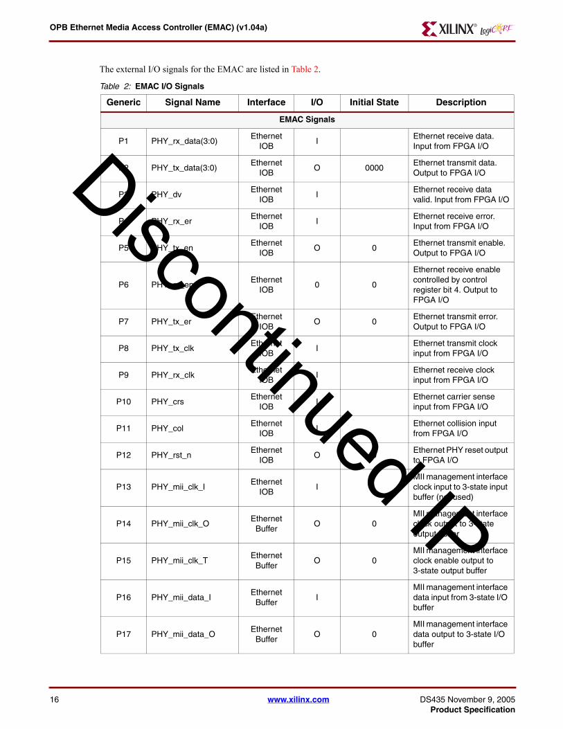
OPB Ethernet Media Access Controller (EMAC) (v104a)
DS435 NovProduct Sp
D
P18 PHY_mii_data_T
Ethernet Buffer
O 0MII management interface data enable output to 3-state IO buffer
OPB Signals
P19Sln_DBus(0C_OPB_DWIDTH-1)
OPB bus O 0EMAC slave output data bus
P20 Sln_xferAck OPB bus O 0EMAC slave transfer acknowledge
P21 Sln_Retry OPB bus O 0 EMAC slave retry
P22 Sln_ToutSup OPB bus O 0EMAC slave timeout suppress
P23 Sln_ErrAck OPB bus O 0EMAC slave error acknowledge
P24OPB_ABus(0C_OPB_AWIDTH-1)
OPB bus I OPB address bus
P25 OPB_BE(03) OPB bus I OPB byte enables
P26OPB_DBus(0C_OPB_DWIDTH-1)
OPB bus I OPB data bus
P27 OPB_RNW OPB bus IRead not Write (OR of all master RNW signals)
P28 OPB_select OPB bus IMaster has taken control of the bus (OR of all master selects)
P29 OPB_seqAddr OPB bus I OPB sequential address
P30 OPB_errAck OPB bus I OPB error acknowledge
P31 OPB_MnGrant OPB bus I OPB master bus grant
P32 OPB_retry OPB bus I OPB retry
P33 OPB_timeout OPB bus I OPB timeout error
P34 OPB_xferAck OPB bus IOPB transfer acknowledge
P35 Mn_request OPB bus O 0 EMAC master bus request
P36 Mn_busLock OPB bus O 0EMAC master bus arbitration lock
P37 Mn_select OPB bus O 0 EMAC master select
P38 Mn_RNW OPB bus O 0EMAC master Read not Write
P39 Mn_BE(03) OPB bus O 0EMAC master byte enables
P40 Mn_seqAddr OPB bus O 0EMAC master sequential address
Table 2 EMAC IO Signals (Contd)
Generic Signal Name Interface IO Initial State Description
iscontinued IP
ember 9 2005 wwwxilinxcom 17ecification
OPB Ethernet Media Access Controller (EMAC) (v104a)
18
D
EMAC Port DependenciesThe width of some of the EMAC signals depend on parameters selected in the design The dependencies between the EMAC design parameters and IO signals are shown in Table 3
Table 3 EMAC Parameter Port Dependencies
Generic Name Affects Depends Relationship Description
Design Parameters
G20 C_OPB_DWIDTH P18 P26 Specifies the Data Bus width
G19 C_OPB_AWIDTH P24 P41 Specifies the Address Bus width
G17 C_DMA_PRESENT G18 Specifies if DMA is present and which type
G18C_DMA_INTR_COASLESCE
G17Not used if scatter gather DMA not present (G17 is 0 1 2)
IO Signals
P19Sln_DBus(0C_OPB_DWIDTH-1)
G20 Width varies with the size of the Data bus
P24OPB_ABus(0C_OPB_AWIDTH-1)
G19 Width varies with the size of the Address bus
P26OPB_DBus(0C_OPB_DWIDTH-1)
G20 Width varies with the size of the Data bus
P41M_ABus(0C_OPB_AWIDTH-1)
G19 Width varies with the size of the Address bus
EMAC Interrupt InterfaceThe interrupt signals generated by the EMAC are provided as outputs as well as being managed by the Interrupt Source Controller in the EMAC IPIF module This interface provides many of the features commonly provided for interrupt handling Please refer to the Processor IP Reference Guide under Part 1 Embedded Processor IP under IPIF under OPB IPIF Architecture under OPB IPIF Interrupt for a complete description of the IPIF interrupt processing An overview diagram of the interrupt control structure is in Figure 8
P41Mn_ABus(0C_OPB_AWIDTH-1)
OPB bus O 0EMAC master address bus
System
P42 OPB_Clk System I System clock
P43 OPB_Rst System ISystem Reset (active high)
P44 IP2INTC_Irpt System O 0 System Interrupt
P45 Freeze System I System Freeze Input
P46 emac_intrpts(021) Genera Olsquo 0x0C0000 EMAC interrupts
Table 2 EMAC IO Signals (Contd)
Generic Signal Name Interface IO Initial State Description
iscontinued IP
wwwxilinxcom DS435 November 9 2005Product Specification
OPB Ethernet Media Access Controller (EMAC) (v104a)
DS435 NovProduct Sp
D
Figure 8 Interrupt Control Structure
Figure Top x-ref 8
Ethernet IP
IPIF0 1 2 3 4 5 6 7 8 9 10 11 12 13 14 15 16 17 18 19 20 21 22 23 24 25 26 27 28 29 30 31
Device Interrupt Enable Register (RW offset 0x0008)
Device Interrupt lsquoORrsquo
Device Interrupt Status Register (Read Only except bits 30 amp 31 offset 0x0000)
IP2Bus_Error_ sa
lsquoANDrsquo
Device Interrupt Pending Register (Read Only offset 0x0004)
Device Global InterruptEnable
(RW offset 0x001C)
Reserved (IPIF growth)
OPB Ethernet
DMASG
0 1 2 3 4 5 6 7
DMA CH2 (Rx)Interrupts
IPIF ISC
0 1 2 3 4 5 6 7
DMA CH1 (Tx)Interrupts
IPIF ISC
Ethernet Interrupts
IP ISC
0 1 2 3 4 5 6 7 21
WrFIFO RdFIFO
Priority Encoder ampInterrupt ID Register
(Read Only)(offset 0x0018)
ISCISCIPISR (RTOW offset 0x0020)
IPIER (RW offset 0x0028)
TXISR(RTOW offset 0x232C)
RXISR(RTOW offset 0x236C)
TXIER(RW offset 0x2330)
RXIER(RW offset 0x2370)
interrupt_example_etherneteps
The EMAC Interrupts values are available by reading the IP Interrupt status register (offset 0x0020) the interrupt values are shown in Figure 9 and described in Table 4
Figure 9 IPIF Interrupt Status Register (IPISR)
Figure Top x-ref 9
Reserved RAE RSE RFCS RMFE TPPR TLFO TSFO RSVD RERR RXCPRLFE
ipif_interrupt_control_registereps
RLE RLFE RCE RDFO TLFU TFSU RSVD TLFF TSFE TERR TXCP
10 11 12 13 14 15 16 17 18 19 20 21 23 2422 25 26 28 29 3027 31
iscontinued IP
ember 9 2005 wwwxilinxcom 19ecification
OPB Ethernet Media Access Controller (EMAC) (v104a)
20
D
Table 4 EMAC IP Interrupt Status Register Bit Definitions (offset 0x0020)
Bit Location
NameCore
AccessResetValue
Description
0 - 9 RSVD Read 0000000000 Unused
10 RAE ReadTOW rsquo0rsquo Receive Alignment Error interrupt
11 RLE ReadTOW rsquo0rsquo Receive Long Error interrupt
12 RSE ReadTOW rsquo0rsquo Receive Short Error interrupt
13 RLFE ReadTOW rsquo0rsquo Receive Length Field Error interrupt
14 RFCS ReadTOW rsquo0rsquo Receive FCS Error interrupt
15 RCE ReadTOW rsquo0rsquo Receive Collision Error interrupt
16 RMFE ReadTOW rsquo0rsquo Receive Missed Frame Error interrupt
17 RDFO ReadTOW rsquo0rsquo Receive Data FIFO Overrun interrupt
18 TPPR ReadTOW rsquo0rsquo Transmit Pause Packet Received interrupt
19 TLFU ReadTOW rsquo0rsquo Transmit Length FIFO Underrun interrupt
20 TLFO ReadTOW rsquo0rsquo Transmit Length FIFO Overrun interrupt
21 TSFU ReadTOW rsquo0rsquo Transmit Status FIFO Underrun interrupt
22 TSFO ReadTOW rsquo0rsquo Transmit Status FIFO Overrun interrupt
23 RSVD Read rsquo0rsquo Reserved
24 RSVD Read rsquo0rsquo Reserved
25 TLFF ReadTOW rsquo0rsquo Transmit Length FIFO Full interrupt
26 RLFE ReadTOW rsquo1rsquo Receive Length FIFO Empty interrupt
27 TSFE ReadTOW rsquo1rsquo Transmit Status FIFO Empty interrupt
28 RERR ReadTOW rsquo0rsquo Receive Error interrupt
29 TERR ReadTOW rsquo0rsquo Transmit error interrupt
30 RXCP ReadTOW rsquo0rsquo Receive complete interrupt
31 TXCP ReadTOW rsquo0rsquo Transmit complete interrupt
Detailed Interrupt Descriptions
Interrupt (data bus bit 31 emac_intrpts(0) ) -- Transmit complete interrupt
Indicates that at least one transmit has completed and that the transmit status word is available This interrupt is actually Transmit Status Register FIFO not empty This interrupt will stay set as long as at least one status word has not been read from the transmit status word register FIFO
Interrupt (data bus bit 30 emac_intrpts(1) ) -- Receive complete interrupt
Indicates that at least one successful receive has completed and that the receive status word packet data and packet data length is available This signal is not set for unsuccessful receives This interrupt is actually Receive Length Register FIFO not empty This interrupt will stay set as long as at least one length value has not been read from the receive length register FIFO
iscontinued IP
wwwxilinxcom DS435 November 9 2005Product Specification
OPB Ethernet Media Access Controller (EMAC) (v104a)
DS435 NovProduct Sp
D
Interrupt (data bus bit 29 emac_intrpts(2) ) -- Transmit error interrupt
Indicates that at least one failed transmit has completed and that the transmit status word is available This active high signal is one bus clock in width
Interrupt (data bus bit 28 emac_intrpts(3) ) -- Receive Error interrupt
Indicates that at least one failed receive has completed No receive status word packet data or packet data length is available since it is not retained for failed receives
Interrupt (data bus bit 27 emac_intrpts(4) ) -- Transmit Status FIFO Empty interrupt
This reflects the status of the transmit status FIFO empty flag It may be used to indicate that the status words for all completed transmissions have been processed Any other transmit packets already provided to the EMAC are either queued for transmit or are currently being transmitted but have not yet completed This active high signal remains active as long as the condition persists
Interrupt (data bus bit 26 emac_intrpts(5) ) --Receive Length FIFO Empty interrupt
This reflects the status of the receive length FIFO empty flag It may be used to indicate that the packet lengths for all successfully completed receives have been processed The status of this FIFO should always track the status of the receive status FIFO This active high signal remains active as long as the condition persists
Interrupt (data bus bit 25 emac_intrpts(6) ) -- Transmit Length FIFO Full interrupt
This reflects the status of the transmit length FIFO full flag It may be used to pause queueing of transmit packets until some of the queued packets have been processed by the EMAC This active high signal remains active as long as the condition persists
Interrupt (data bus bit 24 emac_intrpts(7) ) -- Reserved
Interrupt (data bus bit 23 emac_intrpts(8) ) -- Reserved
Interrupt (data bus bit 22 emac_intrpts(9) ) -- Transmit Status FIFO Overrun interrupt
Indicates that the Transmit status FIFO became full following the transmission of a packet and data was lost Care must be taken under these conditions to ensure that the transmit status words do not become out of sync with the originating packet information To insure that more data is not lost transmit status words stored in the FIFO should be processed to free up more locations Once set this bit can only be cleared with a reset
Interrupt (data bus bit 21 emac_intrpts(10) ) -- Transmit Status FIFO underrun interrupt
Indicates that an attempt was made to read the transmit status FIFO when it was empty and that the data received is not valid Once set this bit can only be cleared with a reset
Interrupt (data bus bit 20 emac_intrpts(11) ) -- Transmit Length FIFO Overrun interrupt
Indicates that more transmit packets were written to the EMAC transmit queue than the transmit length FIFO could store and data was lost This is non-recoverable condition since some or all of the packet data may have been stored in the transmit data FIFO and it can not be removed
Since there is not a transmit length entry for that packet the transmit length and data FIFOs are no longer synchronized This condition should be corrected by forcing an immediate reset of the transmit data FIFO and the transmit path in the EMAC Once set this bit can only be cleared with a reset
Interrupt (data bus bit 19 emac_intrpts(12) ) -- Transmit Length FIFO Underrun interrupt
Indicates that the EMAC attempted to remove an entry from the transmit length FIFO following the completion of a transmission and there were no entries in the FIFO This should never be possible and represents a serious
iscontinued IP
ember 9 2005 wwwxilinxcom 21ecification
OPB Ethernet Media Access Controller (EMAC) (v104a)
22
D
error This condition should be corrected by forcing an immediate reset of the transmit data FIFO and the transmit path in the EMAC condition Once set this bit can only be cleared with a reset
Interrupt (data bus bit 18 emac_intrpts(13) ) -- Transmit Pause Packet Received interrupt
Indicates that transmissions has paused as requested by a received pause packet
Interrupt (data bus bit 17 emac_intrpts(14) ) -- Receive Data FIFO Overrun interrupt
Indicates that the receive data FIFO became full during the reception of a packet and data was lost The EMAC will remove the partial packet from the receive data FIFO and no receive status or length will be stored but to insure that more data is not lost receive packets stored in the FIFO should be processed to free up more locations
Interrupt (data bus bit 16 emac_intrpts(15 ) ) -- Receive Missed Frame Error interrupt
Indicates that at least one frame addressed to the EMAC under the current address validation modes could not be received and the corresponding data was lost
Interrupt (data bus bit 15 emac_intrpts(16 ) ) -- Receive Collision Error interrupt
Indicates that at least one frame could not be received due to a collision and the corresponding data was lost
Interrupt (data bus bit 14 emac_intrpts(17) ) -- Receive FCS Error interrupt
Indicates that at least one frame addressed to the EMAC under the current address validation modes contained an FCS error and the corresponding data was discarded
Interrupt (data bus bit 13 emac_intrpts(18) ) -- Receive Length Field Error interrupt
Indicates that at least one frame addressed to the EMAC under the current address validation modes contained a length field which did not match the actual frame length and the corresponding data was discarded
Interrupt (data bus bit 12 emac_intrpts(19) ) -- Receive Short Error interrupt
Indicates that at least one frame addressed to the EMAC under the current address validation modes was shorter than allowed and the corresponding data was discarded
Interrupt (data bus bit 11 emac_intrpts(20) ) -- Receive Long Error interrupt
Indicates that at least one frame addressed to the EMAC under the current address validation modes was longer than allowed and the corresponding data was discarded
Interrupt (data bus bit 10 emac_intrpts(21) ) -- Receive Alignment Error interrupt
Indicates that at least one frame addressed to the EMAC under the current address validation modes was not integral number of bytes in length corresponding data was truncated to the last full byte
EMAC Register Definition
EMAC IPIF Registers
The EMAC design contains registers in each of the two modules (IPIF and EMAC core) The registers listed in Table 5 are contained in the IPIF module and are included for completeness of this specification Detailed descriptions of these registers are provided in the IPIF specifications listed in the Reference Documents section The presence of the DMA registers varies based on the setting of the C_DMA_PRESENT parameter The Device Interrupt Identification Register will not be present if the C_INCLUDE_DEV_PENCODER is set to rsquo0rsquo
The registers listed in Table 6 are contained in the EMAC core module and are described in detail in this specification The addresses for all registers are based on a parameter which is the base address for the entire EMAC module The address of each register is then calculated by an offset to the base address
iscontinued IP
wwwxilinxcom DS435 November 9 2005Product Specification
OPB Ethernet Media Access Controller (EMAC) (v104a)
DS435 NovProduct Sp
D
Table 5 EMAC IPIF Registers
Register Name OPB ADDRESS Access
Transmit DMA amp Scatter Gather Reset Register C_DEV_BASEADDR + 0x2300 Write
Transmit DMA amp Scatter Gather Module Identification Register
C_DEV_BASEADDR + 0x2300 Read
Transmit DMA amp Scatter Gather Control Register C_DEV_BASEADDR + 0x2304 ReadWrite
Transmit DMA amp Scatter Gather source address C_DEV_BASEADDR + 0x2308 ReadWrite
Transmit DMA amp Scatter Gather destination address
C_DEV_BASEADDR + 0x230C ReadWrite
Transmit DMA amp Scatter Gather startlength C_DEV_BASEADDR + 0x2310 ReadWrite
Transmit DMA amp Scatter Gather Status Register C_DEV_BASEADDR + 0x2314 Read
Transmit DMA amp Scatter Gather Buffer Descriptor Address
C_DEV_BASEADDR + 0x2318 ReadWrite
Transmit DMA Software Control Register C_DEV_BASEADDR + 0x231C ReadWrite
Transmit DMA amp Scatter Gather Unserviced Packet Count
C_DEV_BASEADDR + 0x2320 ReadWrite
Transmit DMA amp Scatter Gather Packet Count Threshold
C_DEV_BASEADDR + 0x2324 ReadWrite
Transmit DMA amp Scatter Gather Packet Wait Bound
C_DEV_BASEADDR + 0x2328 ReadWrite
Transmit DMA amp Scatter Gather Interrupt Status Register
C_DEV_BASEADDR + 0x232CReadToggle on
Write
Transmit DMA amp Scatter Gather Interrupt Enable Register
C_DEV_BASEADDR + 0x2330 ReadWrite
Receive DMA amp Scatter Gather Reset Register C_DEV_BASEADDR + 0x2340 Write
Receive DMA amp Scatter Gather Module Identification Register
C_DEV_BASEADDR + 0x2340 Read
Receive DMA amp Scatter Gather Control Register C_DEV_BASEADDR + 0x2344 ReadWrite
Receive DMA amp Scatter Gather source address C_DEV_BASEADDR + 0x2348 ReadWrite
Receive DMA amp Scatter Gather destination address
C_DEV_BASEADDR + 0x234C ReadWrite
Receive DMA amp Scatter Gather startlength C_DEV_BASEADDR + 0x2350 ReadWrite
Receive DMA amp Scatter Gather Status Register C_DEV_BASEADDR + 0x2354 Read
Receive DMA amp Scatter Gather Buffer Descriptor Address
C_DEV_BASEADDR + 0x2358 ReadWrite
Receive DMA Software Control Register C_DEV_BASEADDR + 0x235C ReadWrite
Receive DMA amp Scatter Gather Unserviced Packet Count
C_DEV_BASEADDR + 0x2360 ReadWrite
Receive DMA amp Scatter Gather Packet Count Threshold
C_DEV_BASEADDR + 0x2364 ReadWrite
iscontinued IP
ember 9 2005 wwwxilinxcom 23ecification
OPB Ethernet Media Access Controller (EMAC) (v104a)
24
D
EMAC Core Registers
The EMAC core registers are listed in Table 6
Receive DMA amp Scatter Gather Packet Wait Bound C_DEV_BASEADDR + 0x2368 ReadWrite
Receive DMA amp Scatter Gather Interrupt Status Register
C_DEV_BASEADDR + 0x236CReadToggle on
Write
Receive DMA amp Scatter Gather Interrupt Enable Register
C_DEV_BASEADDR + 0x2370 ReadWrite
Write Packet FIFO reset (write) Module Identification (read)
C_DEV_BASEADDR + 0x2000 ReadWrite
Write Packet FIFO Vacancy C_DEV_BASEADDR + 0x2004 Read
Write Packet FIFO Push C_DEV_BASEADDR + 0x2008 Write
Write Packet FIFO data write portC_DEV_BASEADDR + 0x2100 thru 0x28FF
Write
Read Packet FIFO reset (write) Module Identification (read)
C_DEV_BASEADDR + 0x2010 ReadWrite
Read Packet FIFO Occupancy C_DEV_BASEADDR + 0x2014 Read
Read Packet FIFO Pop C_DEV_BASEADDR + 0x2018 Write
Read Packet FIFO data read portC_DEV_BASEADDR + 0x2200 thru 0x29FF
Read
Device Interrupt Status Register C_DEV_BASEADDR + 0x0000 Read
Device Interrupt Pending Register C_DEV_BASEADDR + 0x0004 Read
Device Interrupt Enable Register C_DEV_BASEADDR + 0x0008 ReadWrite
Device Interrupt Identification Register C_DEV_BASEADDR + 0x0018 Read
Device Global Interrupt Enable C_DEV_BASEADDR + 0x001C ReadWrite
IP Interrupt Status Register C_DEV_BASEADDR + 0x0020ReadToggle on
Write
IP Interrupt Enable Register C_DEV_BASEADDR + 0x0028 ReadWrite
Device Software Reset (write) Module Identification (read) Register
C_DEV_BASEADDR + 0x0040 ReadWrite
Table 6 EMAC Core Registers
Register Name OPB ADDRESS Access
EMAC Module Identification Register (EMIR) C_DEV_BASEADDR + 0x1100 Read
EMAC Control Register (ECR) C_DEV_BASEADDR + 0x1104 ReadWrite
Interframe Gap Register (IFGP) C_DEV_BASEADDR + 0x1108 ReadWrite
Station Address High (SAH) C_DEV_BASEADDR + 0x110C ReadWrite
Station Address Low (SAL) C_DEV_BASEADDR + 0x1110 ReadWrite
Table 5 EMAC IPIF Registers (Contd)
Register Name OPB ADDRESS Access
iscontinued IP
wwwxilinxcom DS435 November 9 2005Product Specification
OPB Ethernet Media Access Controller (EMAC) (v104a)
DS435 NovProduct Sp
D
EMAC Module Identification Register (EMIR offset 0x1100)
The EMAC Version Register provides the software with a convenient method of verifying the Ethernet IP version and type
Figure 10 EMAC Module Identification Register (EMIR)
Figure Top x-ref 10
0 3 4 10 11 15 16 23 24 31
BLID
REVL
MNRV BTYP
emac_module_identification_registerepsMJRV
MII Management Control Register (MGTCR) C_DEV_BASEADDR + 0x1114 ReadWrite
MII Management Data Register (MGTDR) C_DEV_BASEADDR + 0x1118 ReadWrite
Receive Packet Length Register (RPLR) C_DEV_BASEADDR + 0x111C Read
Transmit Packet Length Register (TPLR) C_DEV_BASEADDR + 0x1120 ReadWrite
Transmit Status Register (TSR) C_DEV_BASEADDR + 0x1124 Read
Receive Missed Frame Count (RMFC) C_DEV_BASEADDR + 0x1128 Read
Receive Collision Count (RCC) C_DEV_BASEADDR + 0x112C Read
Receive FCS Error Count (RFCSEC) C_DEV_BASEADDR + 0x1130 Read
Receive Alignment Error Count (RAEC) C_DEV_BASEADDR + 0x1134 Read
Transmit Excess Deferral Count (TEDC) C_DEV_BASEADDR + 0x1138 Read
Receive Status Reg (RSR) C_DEV_BASEADDR + 0x113C Read
Receive CAM Entry High Reg (CAMH) C_DEV_BASEADDR + 0x1140 ReadWrite
Receive CAM Entry Low Reg (CAML) C_DEV_BASEADDR + 0x1144 ReadWrite
Table 7 EMAC Module Identification Register Bit Definitions
Bits NameCore
AccessResetValue
Description
0 - 3Major Version Number (MJRV)
ReadVersion ID0001 for this major version of 1
Module Major Version Number
4 - 10Minor Version Number (MNRV)
ReadVersion ID 0000010 for this minor version of 2
Module Minor Version Number
Table 6 EMAC Core Registers (Contd)
Register Name OPB ADDRESS Access
iscontinued IP
ember 9 2005 wwwxilinxcom 25ecification
OPB Ethernet Media Access Controller (EMAC) (v104a)
26
D
EMAC Control Register (ECR offset 0x1104)
The EMAC Control Register shown in Figure 11 and described in Table 8 controls the operation of the EMAC Please note that some of these bits should not be changed while transmit and receive are enabled (ECRENTX andor ECRENRX =rsquo1rsquo)
Figure 11 EMAC Control Register (ECR)
Figure Top x-ref 11
RSTTXRSTRX
ENPHYTXFCS
TXERR ILBE RSVD MA PA RXJB IPPE CAMW Reserved
emac_control_registerepsFD ENTX
ENRXTXPAD
TXSASAOE STRP UA BA REO CAME RSVD
0 1 2 3 4 5 6 7 8 9 10 11 12 13 14 15 16 17 18 19 20 21 23 2422 31
11 -15Rev Letter (REVL)
ReadVersion ID 00000 for this revision of a
Module Minor Version Letter This is a binary encoding of small case letters a through z (00000 - 11001)
16 - 23 Block ID (BLID) Read
Assigned by Platform Generator defaults to 00000001
Block ID Number Distinct number for each EMAC instantiated by Platform Generator
24 - 31Block Type (BTYP)
Read 00000001Block Type This is an 8 bit identifier unique to each IP type For EMAC this type is hex 01
Table 7 EMAC Module Identification Register Bit Definitions (Contd)
Bits NameCore
AccessResetValue
Description
iscontinued IP
wwwxilinxcom DS435 November 9 2005Product Specification
OPB Ethernet Media Access Controller (EMAC) (v104a)
DS435 NovProduct Sp
D
Table 8 EMAC Control Register Bit Definitions
Bit(s) NameCore
AccessResetValue
Description
0 FD ReadWrite rsquo0rsquo
Full Duplex Selects either full duplex mode (ie EMAC can receive and transmit simultaneously on a dedicated Ethernet bus segment) or half duplex mode Choosing half duplex enables CSMACD mode Choosing full duplex mode disables CCSMACD mode It is the responsibility of the software to ensure that this mode matches the PHY if the PHY is operating in auto-negotiation mode This bit should not be modified while transmit and receive are enabled ECRENTX andor ECRENRX =rsquo1rsquo
bull rsquo0rsquo -Half Duplex
bull rsquo1rsquo - Full Duplex
1 RSTTX ReadWrite rsquo1rsquo
Reset Transmitter Immediately resets the transmitter circuitry regardless of its current state The transmitter circuitry will remain in reset until this bit is set to rsquo0rsquo
bull rsquo0rsquo - Normal Operation
bull rsquo1rsquo - Reset
2 ENTX ReadWrite rsquo0rsquo
Enable Transmitter The transmitter circuitry will leave the idle state and begin transmission of a packet only when this bit is rsquo1rsquo and the transmit length register is not empty Setting this bit to rsquo0rsquo will cause the transmitter to enter the idle state after completion of any packet transmission in progress (graceful halt)
bull rsquo0rsquo - Disable Transmitter
bull rsquo1rsquo- Enable Transmitter
3 RSTRX ReadWrite rsquo1rsquo
Reset Receiver Immediately resets the receiver circuitry regardless of its current state The receiver circuitry will remain in reset until this bit is set to rsquo0rsquo
bull rsquo0rsquo - Normal Operation
bull rsquo1rsquo - Reset
4 ENRX ReadWrite rsquo0rsquo
Enable Receiver The receiver circuitry will leave the idle state and begin monitoring the Ethernet bus only when this bit is rsquo1rsquo Setting this bit to rsquo0rsquo will cause the receiver to enter the idle state after completion of any packet reception in progress (graceful halt) This bit also controls the output signal PHY_rx_en
bull rsquo0rsquo - Disable Receiver
bull rsquo1rsquo- Enable Receiver
iscontinued IP
ember 9 2005 wwwxilinxcom 27ecification
OPB Ethernet Media Access Controller (EMAC) (v104a)
28
D
5 ENPHY ReadWrite rsquo1rsquo
Enable PHY This value of this bit is driven to the PHY interface PHY_rst_n signal If the external PHY supports this signal and this bit is rsquo0rsquo the PHY will reset and remain in reset until this bit is set to rsquo1rsquo PHY_rst_n will also be driven active while OPB_Rst is active regardless of value of this bit PHY_rst_n can also be driven active by writing to the Device Software Reset Register if the software reset function has been included in the build The software reset function is not dependent on the value of this bit
bull rsquo0rsquo - Disable Reset PHY
bull rsquo1rsquo- Enable PHY
6 TXPAD ReadWrite rsquo1rsquo
Enable Transmit Auto Pad Insertion Enables automatic pad field insertion by the EMAC circuitry if it is necessary When this is enabled the transmit packet data provided to the EMAC should not contain pad data When this is enabled auto FCS insertion must also be selected to insure correct FCS calculation over the pad field When this is disabled the transmit packet data provided to the EMAC should contain pad data if required This bit should not be modified while transmit and receive are enabled ECRENTX =rsquo1rsquo andor ECRENRX =rsquo1rsquo
bull rsquo0rsquo - Disable Auto Pad Insertion
bull rsquo1rsquo- Enable Auto Pad Insertion
7 TXFCS ReadWrite rsquo1rsquo
Enable Transmit Auto FCS Insertion Enables automatic FCS field insertion by the EMAC circuitry When this is enabled the transmit packet data provided to the EMAC should not contain FCS data When this is disabled the transmit packet data provided to the EMAC should contain FCS data This bit should not be modified while transmit and receive are enabled ECRENTX =rsquo1rsquo andor ECRENRX =rsquo1rsquo
bull rsquo0rsquo - Disable Auto FCS Insertion
bull rsquo1rsquo- Enable Auto FCS Insertion
8 TXSA ReadWrite rsquo1rsquo
Enable Transmit Auto Source Address Insertion Enables automatic source address field insertion from the Station Address Registers by the EMAC circuitry When this is enabled the transmit packet data provided to the EMAC should not contain source address data When this is disabled the transmit packet data provided to the EMAC should contain source address data This bit should not be modified while transmit and receive are enabled ECRENTX =rsquo1rsquo andor ECRENRX =rsquo1rsquo
bull rsquo0rsquo - Disable Auto Source Address Insertion
bull rsquo1rsquo- Enable Auto Source Address Insertion
Table 8 EMAC Control Register Bit Definitions (Contd)
Bit(s) NameCore
AccessResetValue
Description
iscontinued IP
wwwxilinxcom DS435 November 9 2005Product Specification
OPB Ethernet Media Access Controller (EMAC) (v104a)
DS435 NovProduct Sp
D
9 TXERR ReadWrite rsquo0rsquo
Transmit Error Insertion The value of this bit is driven to the PHY interface TX_ER signal If the external PHY supports this mode it will inject an error encoded byte into the transmit data when operating in 100 Base-T mode The PHY will ignore this input when operating in 10Base-T mode This bit should not be modified while transmit and receive are enabled ECRENTX =rsquo1rsquo andor ECRENRX =rsquo1rsquo
bull rsquo0rsquo - Disable Error Insertion
bull rsquo1rsquo - Enable Error Insertion
10 SAOE ReadWrite rsquo1rsquo
Source Address Overwrite Enable When set to rsquo1rsquo it enables overwriting of the source address field provided in the packet data to be transmitted The source address field is overwritten with the value contained in the SAH and SAL registers When set to rsquo0rsquo the source address field is not included in the packet data to be transmitted and the value contained in the SAH and SAL registers is inserted into the packet data stream This bit is only used when auto source address insertion is enabled ECRTXSA =rsquo1rsquo
11 ILBE ReadWrite rsquo0rsquo
Internal Loop-Back Enable Enables looping of the transmit data directly to the receive data path internally to the EMAC The transmit and receive paths are isolated from the external PHY
12 STRP ReadWrite rsquo0rsquo
Pad amp FCS Strip Enable Enables stripping of receive pad and FCS fields when typelength field is a length
bull rsquo0rsquo - Disable Strip
bull rsquo1rsquo - Enable Strip
13 Reserved Read rsquo0rsquo bull Reserved This bit is reserved for future use
14 UA ReadWrite rsquo1rsquo
Enable Unicast Address Enables the EMAC to accept valid frames that have a destination address field that matches the value in the station address registers This bit should not be modified while transmit and receive are enabled ECRENTX =rsquo1rsquo andor ECRENRX =rsquo1rsquorsquo
bull rsquo0rsquo - Disable Unicast Address
bull rsquo1rsquo - Enable Unicast Address
15 MA ReadWrite rsquo0rsquo
Enable Multicast Address Enables the EMAC to accept valid frames that have a multicast (excluding broadcast) destination address field This bit should not be modified while transmit and receive are enabled ECRENTX =rsquo1rsquo andor ECRENRX =rsquo1rsquorsquo
bull rsquo0rsquo - Disable Multicast Address
bull rsquo1rsquo - Enable Multicast Address
Table 8 EMAC Control Register Bit Definitions (Contd)
Bit(s) NameCore
AccessResetValue
Description
iscontinued IP
ember 9 2005 wwwxilinxcom 29ecification
OPB Ethernet Media Access Controller (EMAC) (v104a)
30
D
16 BA ReadWrite rsquo1rsquo
Enable Broadcast Address Enables the EMAC to accept valid frames that have a broadcast destination address field This bit should not be modified while transmit and receive are enabled ECRENTX =rsquo1rsquo andor ECRENRX =rsquo1rsquo
bull rsquo0rsquo - Disable Broadcast Address
bull rsquo1rsquo - Enable Broadcast Address
17 PA ReadWrite rsquo0rsquo
Enable Promiscuous Address Mode Enables the EMAC to accept valid frames This bit should not be modified while transmit and receive are enabled ECRENTX =rsquo1rsquo andor ECRENRX =rsquo1rsquo
bull rsquo0rsquo - Disable Promiscuous Address Mode
bull rsquo1rsquo - Enable Promiscuous Address Mode
18 REO ReadWrite rsquo0rsquo
Receive Error Override Enables the EMAC to attempt to receive and store frames even if they contain errors
bull rsquo0rsquo - Disable Error Override
bull rsquo1rsquo - Enable Error Override
19 RXJB ReadWrite 0
Receive Jumbo Frames Enable Enables the EMAC to receive jumbo size frames This bit can not be set if the jumbo functionality was not included using the parameter C_JUMBO_EXIST
bull rsquo0rsquo - Disable Rx Jumbo Frames
bull rsquo1rsquo - Enable Rx Jumbo Frames
20 CAME ReadWrite 0
Receive CAM Enable Enables the EMAC to use the 64 entry CAM for receive address validation This bit can not be set if the CAM was not included using the parameter C_CAM_EXIST
bull rsquo0rsquo - Disable Rx CAM
bull rsquo1rsquo - Enable Rx CAM
21 IPPE ReadWrite rsquo0rsquo
Interpret Pause Packets Enables the EMAC to process valid received pause packets
bull rsquo0rsquo - Disable Pause Packets
bull rsquo1rsquo - Enable Pause Packets
22 Reserved Read rsquo0rsquo Reserved These bits are reserved for future use
23 CAMW ReadWrite rsquo0rsquo
Receive CAM Write This bit Writes the contents of the CAMH and CAML registers into the CAM address also provided in CAMH This bit will automatically reset to rsquo0rsquo Setting this bit will have no effect if the CAM was not included using the parameter C_CAM_EXIST
bull rsquo0rsquo - CAM Write Idle
bull rsquo1rsquo - Initiate a CAM Write
24-31 Reserved Read 0x000 Reserved These bits are reserved for future use
Table 8 EMAC Control Register Bit Definitions (Contd)
Bit(s) NameCore
AccessResetValue
Description
iscontinued IP
wwwxilinxcom DS435 November 9 2005Product Specification
OPB Ethernet Media Access Controller (EMAC) (v104a)
DS435 NovProduct Sp
D
Interframe Gap Register (IFGP offset 0x1108)
The Interframe Gap Register shown in Figure 12 and described in Table 9 controls the duration of the interframe Gap The Interframe Gap is the sum of IFGP1 and IFGP2 measuring in units of the bit time multiplied by four Please refer to the paragraph Interframe Gap and Deferring for information about how the Interframe Gap is used by the EMAC Please note that these settings should not be changed while transmit and receive are enabled (ECRENTX andor ECRENRX =rsquo1rsquo)
Figure 12 Interframe Gap Register (IFGP)
Figure Top x-ref 12
0 4 5 9 10
IFGP2
interframe_gap_registerepsIFGP1 Reserved
Table 9 Interframe Gap Register Bit Definitions
Bit(s) NameCore
AccessResetValue
Description
0-4 IFGP1 ReadWrite 10000
Interframe Gap Part 1 A value of 1 in this field would provide a 4 bit time interframe part 1 gap to be combined with the interframe part 2 gap for the total interframe gap time The reset value for this field is value recommended for most operation by IEEE Std 8023 This field should not be modified while transmit and receive are enabled ECRENTX =rsquo1rsquo andor ECRENRX =rsquo1rsquo
5-9 IFGP2 ReadWrite 01000
Interframe Gap Part 2 A value of 1 in this field would provide a 4 bit time interframe part 2 gap to be combined with the interframe part 1 gap for the total interframe gap time The reset value for this field is value recommended for most operation by IEEE Std 8023 This field should not be modified while transmit and receive are enabled ECRENTX =rsquo1rsquo andor ECRENRX =rsquo1rsquo
10-31 Reserved Read 0x000000 Reserved These bits are reserved for future use
Receive Packet Length Register (RPLR offset 0x111C)
The receive packet length register is actually a FIFO of register values each corresponding to a valid frame received The data for the frame is stored in the receive data FIFO and the status word is stored in the receive status register FIFO
The width of this register varies based on the value of the parameter C_JUMBO_EXIST If C_JUMBO_EXIST = rsquo1rsquo bits 18 through 31 are used to store the length value where as bits 21 through 31 are used when C_JUMBO_EXIST = rsquo0rsquo
iscontinued IP
ember 9 2005 wwwxilinxcom 31ecification
OPB Ethernet Media Access Controller (EMAC) (v104a)
32
D
The data is written by the EMAC when the framersquos destination address passes the current address validation modes and when the frame has been determined to be valid and the receive data FIFO had enough locations that all of the frame data has been saved The existence of data in the receive packet length FIFO (FIFO empty flag is rsquo0rsquo) may be used to initiate the processing of received packets until this FIFO is empty The interrupt Receive Complete is set when at least one entry is stored in this FIFO from a successful packet reception An interrupt Receive Length FIFO Empty also is available Reading this register causes the current value to be removed from the FIFO The Receive Packet Length register is shown in Figure 13 and described in Table 10
Reading of this register will Flush the RX_DRE of any residue data if C_RX_DRE_TYPEgt0
Figure 13 Receive Packet Length Register (RPLR)
Figure Top x-ref 13
18 19 20 21 31
Reserved RXPL
receive_packet_length_registereps
Table 10 Receive Packet Length Register Bit Definitions
Bit(s) NameCore
AccessResetValue
Description
0-17 or
0-20Reserved Read 0x00000 Reserved These bits are reserved for future use
18-31 or
21-31RXPL Read 0x000
Receive Packet Length The number of bytes of the corresponding receive packet stored in the receive data FIFO
Transmit Packet Length Register (TPLR offset 0x1120)
The transmit packet length register is actually a FIFO of register values each corresponding to a valid frame ready for transmit The data for the frame is stored in the transmit data FIFO
The width of this register varies based on the value of the parameter C_JUMBO_EXIST If C_JUMBO_EXIST = rsquo1rsquo bits 18 through 31 are used to store the length value where as bits 21 through 31 are used when C_JUMBO_EXIST = rsquo0rsquo
The data is written to the EMAC over the external processor bus interface either by simple DMA ScatterGather DMA or by direct memory mapped access
When presenting a transmit packet to the EMAC the packet data should first be written to the transmit data FIFO The existence of data in the transmit packet length FIFO (FIFO empty flag is rsquo0rsquo) is used by the EMAC to initiate the processing of transmit packets until this FIFO is empty
The Transmit Packet Length register shown in Figure 14 and described in Table 11 can be read over the processor interface but only the EMAC can remove a value from the FIFO The EMAC will remove the current length from the FIFO when it completes the corresponding transmission If multiple reads are performed prior to that completion the same value will be returned for each read operation
iscontinued IP
wwwxilinxcom DS435 November 9 2005Product Specification
OPB Ethernet Media Access Controller (EMAC) (v104a)
DS435 NovProduct Sp
D
Writing to this register will cause an automatic Write Push to happen on the Write Packet FIFO if C_TX_DRE_TYPEgt0
Figure 14 Transmit Packet Length Register (TPLR)
Figure Top x-ref 14
18 19 20 21 31
Reserved TXPL
transmit_packet_length_registereps
Table 11 Transmit Packet Length Register Bit Definitions
Bit(s) NameCore
AccessResetValue
Description
0-17or
0-20Reserved Read 0x00000 Reserved These bits are reserved for future use
18-31 or
21-31TXPL ReadWrite 0x000
Transmit Packet Length The number of bytes of the corresponding transmit packet stored in the transmit data FIFO
Receive Status Register (RSR offset 0x113C)
The receive status register shown in Figure 15 and described in Table 12 is a place holder for the receive status register that is used by the Scatter Gather DMA interface The EMAC does not need a receive status register but is required to provide the correct value in bit 31 to the generalized Scatter Gather DMA circuitry as part of a standard receive packet operation
Note that when C_RX_INCLUDE_CSUM is true this value is written into the RDPFIFO along with the RAW checksum
Figure 15 Receive Status Register (RSR)
Figure Top x-ref 15
31
Reserved RPCF
receive_status_registereps
iscontinued IP
ember 9 2005 wwwxilinxcom 33ecification
OPB Ethernet Media Access Controller (EMAC) (v104a)
34
D
Table 12 Receive Status Register Bit Definitions
Bit(s) NameCore
AccessResetValue
Description
0 - 30 Reserved NA 0x00000000Reserved These bits are unused and will always return all zeros
31 RPCF Read rsquo1rsquo
Receive Packet Complete Flag This bit is always rsquo1rsquo and is used to indicate to the software that a buffer descriptor associated with this packet has been completely processed by the DMA circuitry and is available for software use
Transmit Status Register (TSR offset 0x1124)
The transmit status register shown in Figure 16 and described in Table 13 is actually a FIFO of register values each corresponding to a frame transmission attempt The bits in this register reflect the specific status of the corresponding transmit operation including the EMAC settings which were applied to the transmit operation Reading this register causes the current value to be removed from the FIFO
Figure 16 Transmit Status Register (TSR)
Figure Top x-ref 16
0 1 2 6 7 8 31
TXED TXA Reserved TPCF
transmit_status_registerepsRFIFOU TXLC
iscontinued IP
wwwxilinxcom DS435 November 9 2005Product Specification
OPB Ethernet Media Access Controller (EMAC) (v104a)
DS435 NovProduct Sp
D
Table 13 Transmit Status Register Bit Definitions
Bit(s) NameCore
AccessReset Value Description
0 TXED Read rsquo0rsquo
Transmit Excess Deferral Error This bit is only applicable in half-duplex mode It indicates that at least one transmit frame was not able to complete transmission due to collisions that exceed the maximum number of retries (16) This bit is cleared to rsquo0rsquo when read
bull rsquo0rsquo - No excess deferrals occurred since the last read
bull rsquo1rsquo - At least one excess deferral has occurred
1 PFIFOU Read rsquo0rsquo
Packet Fifo Underrun This bit indicates that at least one transmit frame experienced a packet FIFO underrun condition during transmission This bit is cleared to rsquo0rsquo when read
bull rsquo0rsquo - No packet FIFO underruns occurred since the last read
rsquo1rsquo - At least one packet FIFO underrun has occurred
2- 6 TXA Read 0x00
Transmission Attempts The number of transmission attempts made There will be a maximum of 16 attempts
7 TXLC Read rsquo0rsquo
Transmit Late Collision Error This bit is only applicable in half-duplex mode It indicates a non-recoverable collision occurred more than 64-bit times after the start of the transmission No automatic retransmission can be attempted by the EMAC A late collision should never occur on a compliant Ethernet network
bull rsquo0rsquo - No late collisions occurred
bull rsquo1rsquo - Late collision occurred
8 - 30 Reserved NA 0x000000Reserved These bits are unused and will always return all zeros
31 TPCF Read rsquo1rsquo
Transmit Packet Complete Flag This bit is always rsquo1rsquo and is used to indicate to the software that a buffer descriptor associated with this packet has been completely processed by the DMA circuitry and is available for software use
Station Address High Register (SAH offset 0x110C)
The station address high register shown inFigure 17 and described in Table 14 contains the high-order 16 bits of the 48 bit station address
iscontinued IP
ember 9 2005 wwwxilinxcom 35ecification
OPB Ethernet Media Access Controller (EMAC) (v104a)
36
D
Figure 17 Station Address High (SEH) Register
Figure Top x-ref 17
16 31
Reserved SAH
station_address_high_registereps
Table 14 Station Address High Register Bit Definitions
Bit(s) NameCore
AccessResetValue
Description
0-15 Reserved Read 0x0000 Reserved These bits are reserved for future use
16-31 SAH ReadWrite 0x0000Station Address High This register should not be modified while transmit and receive are enabled ECRENTX =rsquo1rsquo andor ECRENRX =rsquo1rsquo
Station Address Low Register (SAL offset 0x1110)
The station address low register shown inFigure 18 and described in Table 15 contains the low-order 32 bits of the 48 bit station address
Figure 18 Station Address Low (SAL) Register
Figure Top x-ref 18
310
SAL
station_address_low_registereps
Table 15 Station Address Low Register Bit Definitions
Bit(s) NameCore
AccessResetValue
Description
0-31 D0 - D31 ReadWrite 0x00000000
Station Address Low This register should not be modified while transmit and receive are enabled ECRENTX =rsquo1rsquo andor ECRENRX =rsquo1rsquorsquo
MII Management Control Register (MGTCR offset 0x1114)
The MII management control register shown in Figure 19 and described in Table 16 is used with the MII management data register to perform read and writes between the EMAC and the external PHY device via the MII management interface
iscontinued IP
wwwxilinxcom DS435 November 9 2005Product Specification
OPB Ethernet Media Access Controller (EMAC) (v104a)
DS435 NovProduct Sp
D
Figure 19 MII Management Control Register (MGTCR)
Figure Top x-ref 19
mii_mngmnt_control_registereps
0 1 2 6 7 11 12 13 14
SB IEPHYAD
RWN REGAD MIIRE
Reserved
Table 16 MII Management Control Register Bit Definitions
Bit(s) NameCore
AccessResetValue
Description
0 SB ReadWrite rsquo0rsquo
Start Busy writing a rsquo1rsquo to this bit initiates an MII read or write operation The EMAC will clear this bit to rsquo0rsquo when the operation has been completed
bull rsquo0rsquo - No MII Operation in Progress
bull rsquo1rsquo- MII Read or Write in Progress
1 RWN ReadWrite rsquo1rsquo
Read Write Not This bit indicates the direction of the MII operation
bull rsquo0rsquo - Write to PHY register
bull rsquo1rsquo- Read from PHY register
2-6 PHYAD ReadWrite 0x00PHY Address This field is used to specify the address of the PHY to be accessed
7-11 REGAD ReadWrite 0x00Register Address This field is used to specify the register in the PHY to be accessed
12 IE ReadWrite rsquo0rsquo
MII Management Interface Enable This bit controls the 3-state drivers for the MII management signal interface to the PHY
bull rsquo0rsquo - The MII management signals to the PHY are 3-stated
bull rsquo1rsquo - The MII management signals to the PHY are driven and controlled by the EMAC management interface
13 MIIRE Read rsquo0rsquo
MII Management Read Error Indicates that a read from a PHY register is invalid and the operation should be retried This is indicated during a read turn-around cycle when the PHY does not drive the MDIO signal to the low state This bit is cleared to rsquo0rsquo when read
bull rsquo0rsquo - No read errors occurred since the last read
bull rsquo1rsquo - At least one read error has occurred
14-31 Reserved Read 0x00000 Reserved These bits are reserved for future use
iscontinued IP
ember 9 2005 wwwxilinxcom 37ecification
OPB Ethernet Media Access Controller (EMAC) (v104a)
38
D
MII Management Data Register (MGTDR offset 0x1118)
The MII management data register shown in Figure 20 and described in Table 17 is used with the MII management control register to perform read and writes between the EMAC and the external PHY device via the MII management interface For a PHY register write operation data should be written to the data register prior to the write to the control register
Figure 20 MII Management Data Register (MGTDR)
Figure Top x-ref 20
16 31
Reserved MIID
mii_mngmnt_data_registereps
Table 17 MII Management Data Register Bit Definitions
Bit(s) NameCore
AccessResetValue
Description
0 - 15 Reserved NA 0x0000Reserved These bits are unused and will always return all zeros
16-31 MIID ReadWrite 0x0000 MII Management Data Register
Receive Missed Frame Count (RMFC offset 0x1128)
The receive missed frame count register is shown in Figure 21 and described in Table 18 This register value represents the number of missed valid frames since the last reset with destination addresses that pass the current address validation modes
Figure 21 Received Missed Frame Count (RMFC) Register
Figure Top x-ref 21
16 31
Reserved RMFC
receive_missed_frame_count_registereps
Table 18 Receive Missed Frame Count Bit Definitions
Bit(s) NameCore
AccessResetValue
Description
0 - 15 Reserved NA 0x0000Reserved These bits are unused and will always return all zeros
16-31 RMFC Read 0x0000 Receive Missed Frame Count
iscontinued IP
wwwxilinxcom DS435 November 9 2005Product Specification
OPB Ethernet Media Access Controller (EMAC) (v104a)
DS435 NovProduct Sp
D
Receive Collision Count (RCC offset 0x112C)
The receive collision count register value represents the number of received frames that were interrupt by a collision since the last reset These frames may or may not have satisfied the current address validation modes This counter is not used in full duplex mode The receive collision count register is shown in Figure 22 and described in Table 19
Figure 22 Receive Collision Count (RCC) Register
Figure Top x-ref 22
16 31
Reserved RCC
receive_collision_count_registereps
Table 19 Receive Collision Count Bit Definitions
Bit(s) NameCore
AccessResetValue
Description
0 - 15 Reserved NA 0x0000Reserved These bits are unused and will always return all zeros
16-31 RCC Read 0x0000 Receive Collision Count
Receive FCS Error Count (RFCSEC offset 0x1130)
This register value represents the number of received frames since the last reset with destination addresses that pass the current address validation modes but with FCS validation failures The RFCSEC register is shown in Figure 23 and described in Table 20
Figure 23 Receive FCS Error Count (RFCSEC) Register
Figure Top x-ref 23
16 31
Reserved RFCSEC
receive_fcs_error_count_registereps
Table 20 Receive FCS Error Count Bit Definitions
Bit(s) NameCore
AccessResetValue
Description
0 - 15 Reserved NA 0x0000Reserved These bits are unused and will always return all zeros
16-31 RFCSEC Read 0x0000 Receive FCS Error Count
iscontinued IP
ember 9 2005 wwwxilinxcom 39ecification
OPB Ethernet Media Access Controller (EMAC) (v104a)
40
D
Receive Alignment Error Count (RAEC offset 0x1134)
This register value represents the number of received frames since the last reset with an odd number of nibbles that pass the current address validation modes and FCS validation with the extra nibbles truncated The RAEC register is shown in Figure 24 and described in Table 21
Figure 24 Receive Alignment Error Count (RAEC) Register
Figure Top x-ref 24
16 31
Reserved RAEC
receive_alignment_error_count_registereps
Table 21 Receive Alignment Error Count Bit Definitions
Bit(s) NameCore
AccessResetValue
Description
0 - 15 Reserved NA 0x0000Reserved These bits are unused and will always return all zeros
16-31 RAEC Read 0x0000 Receive Alignment Error Count
Transmit Excess Deferral Count (TEDC offset 0x1138)
This register value represents the number of transmitted frames since the last reset that could not be successful transmitted in 16 attempts This counter is not used in full duplex mode The TEDC register is shown in Figure 25 and described in Table 22
Figure 25 Transmit Excess Deferral Count (TEDC) Register
Figure Top x-ref 25
16 31
Reserved TEDC
transmit_exess_deferral_count_registereps
Table 22 Transmit Excess Deferral Count Bit Definitions
Bit(s) NameCore
AccessResetValue
Description
0 - 15 Reserved NA 0x0000Reserved These bits are unused and will always return all zeros
16-31 TEDC Read 0x0000 Transmit Excess Deferral Count
iscontinued IP
wwwxilinxcom DS435 November 9 2005Product Specification
OPB Ethernet Media Access Controller (EMAC) (v104a)
DS435 NovProduct Sp
D
Receive CAM Entry High Register (CAMH offset 0x1140)
The CAMH register shown in Figure 26 and described in Table 23 exists only if the CAM in included in the design (C_CAM_EXIST = rsquo1rsquo) This register contains the address of the CAM location (0 to 63) to which a MAC address will be written along with the upper 16 bits of that MAC address (similar to the SAH register) The MAC address in this register and the CAML register will be written into the CAM at the address provided in this register when ECR bit 23 is set to rsquo1rsquo
Figure 26 Receive CAM Entry High (CAMH) Register
Figure Top x-ref 26
10 15 16 31
Reserved
receive_cam_entry_high_registereps
CAM Address MAC Address
Table 23 Receive CAM Entry High Register Bit Definitions
Bit(s) NameCore
AccessResetValue
Description
0-9 Reserved Read 0000000000 Reserved These bits are reserved for future use
10-15 CAMA ReadWrite 00000 CAM entry address (0 to 63)
16-31 MACH ReadWrite 0x0000 MAC Address High
Receive CAM Entry Low Register (SAL offset 0x1144)
The SAL register shown in Figure 27 and described in Table 24 exists only if the CAM in included in the design (C_CAM_EXIST = rsquo1rsquo) This register contains the lower 32 bits of that MAC address (similar to the SAL register) The MAC address in this register and the CAMH register will be written into the CAM at the address provided in the CAMH register when ECR bit 23 is set to rsquo1rsquo
Figure 27 Receive CAM Entry Low (CAMH) Register
Figure Top x-ref 27
310
receive_cam_entry_low_registereps
MAC Address
Table 24 Receive CAM Entry Low Register Bit Definitions
Bit(s) NameCore
AccessResetValue
Description
0-31 D0 - D31 ReadWrite 0x00000000 MAC Address Low
iscontinued IP
ember 9 2005 wwwxilinxcom 41ecification
OPB Ethernet Media Access Controller (EMAC) (v104a)
42
D
EMAC Block DiagramThe top-level block diagram for the EMAC is shown in Figure 1
Block Diagram TX Control
The block diagram for the TX Control is shown in Figure 28
Figure 28 TX Control Block Diagram
Figure Top x-ref 28
TXFIFO Registers
TX ControlState Machine
InterframeGap Counter
CollisionWindow Counter
ExcessiveDeferral Counter
tx_control_block_diagrameps
RetryCounter
BackoffCounter
LFSR16
TX CRCGenerator
TX Bus FIFO
Block Diagram RX Control
The block diagram for the RX Control is shown in Figure 29
Figure 29 RX Control Block Diagram
Figure Top x-ref 29
RXFIFO Registers
RX ControlState Machine
AddressVaiidation
FCSError Counter
CollisionError Counter
rx_control_block_diagrameps
MissedFrame Counter
ByteCounter
RX CRCGenerator
RX Bus FIFO
EMAC ClocksThe EMAC design has four clock domains that are all asynchronous to each other These clock domains and any special requirements regarding them are discussed below
iscontinued IP
wwwxilinxcom DS435 November 9 2005Product Specification
OPB Ethernet Media Access Controller (EMAC) (v104a)
DS435 NovProduct Sp
D
Transmit Clock (PHY_tx_clk)
The transmit clock [PHY_tx_clk] is generated by the external PHY and must be used by the EMAC to provide transmit data [PHY_tx_data (30)] and control signals [PHY_tx_en and PHY_tx_er] to the PHY The PHY provides one clock cycle for each nibble of data transferred resulting in a 25 MHz clock for 10BASE-T operation and 25 MHz for 100BASE-T operation at +- 100 ppm with a duty cycle of between 35 and 65 inclusive The PHY derives this clock from an external oscillator or crystal
Receive Clock (PHY_rx_clk)
The receive clock [PHY_rx_clk] is also generated by the external PHY but is derived from the incoming Ethernet traffic Like the transmit clock the PHY provides one clock cycle for each nibble of data transferred resulting in a 25 MHz clock for 10BASE-T operation and 25 MHz for 100BASE-T operation with a duty cycle of between 35 and 65 inclusive while incoming data is valid [PHY_dv is rsquo1rsquo]
The minimum high and low times of the receive clock are at least 35 of the nominal period under all conditions The receive clock is used by the EMAC to sample the receive data [PHY_rx_data(30)] and control signals [PHY_dv and PHY_rx_er] from the PHY
MII Management Clock (PHY_mii_clk)
The Management Data Clock (PHY_mii_clk) is driven by the EMAC to the PHY as the reference for data transfer on the PHY_mii_data signal This signal has no maximum high and low times and need not be periodic but must have a minimum high and low time of at least 160 nS with a corresponding minimum period of 400 nS (corresponds to a maximum of 25 MHz) The MII clock will be a divide by 64 from the OPB bus clock for OPB bus frequencies of 65 to 150 MHz range resulting in a PHY_mii_clk of approximately 1 to 23 MHz
Processor Bus Clock (OPB_Clk)
The majority of the EMAC operation functions in the processor bus clock domain This clock must be greater than to equal to 65 MHz in order to transmit and receive Ethernet data at 100 Mbs and greater than to equal to 65 MHz in order to transmit and receive Ethernet data at 10 Mbs
PHY Interface Signals
PHY_rst_n
Some PHYs use a reset input to establish or re-establish a known initial state The EMAC provides the PHY reset signal (PHY_rst_n) for this purpose This active low output is driven active when OPB_Rst is active when the EMAC Control Register bit 5 is rsquo0rsquo or when a soft reset is performed by writing to the Device Software Reset Register (offset 0x0040) when the software reset function is included in the build (C_RESET_PRESENT = rsquo1rsquo)
PHY_tx_en
The EMAC uses the Transmit Enable signal (PHY_tx_en) to indicate to the PHY that it is providing nibbles at the MII interface for transmission It is asserted synchronously to PHY_tx_clk with the first nibble of the preamble and remains asserted while all nibbles have been transmitted PHY_tx_en is negated prior to the first PHY_tx_clk following the final nibble of a frame
This signal is transferred between the PHY_tx_clk and processor clock domains at the asynchronous TX bus FIFO interface The clock to output delay of this signal must be 0 to 25 nS Figure 30 shows PHY_tx_en timing during a transmission with no collisions
iscontinued IP
ember 9 2005 wwwxilinxcom 43ecification
OPB Ethernet Media Access Controller (EMAC) (v104a)
44
D
PHY_rx_en
The EMAC uses the Receive Enable signal (PHY_rx_en) to indicate to the PHY that the PHY should pass or block receive ethernet data The value of this signal is controlled by the EMAC control register (ECR) bit 4 This signal is not used by many PHY devices
Figure 30 Transmission with no collision
Figure Top x-ref 30
transmission_with_no_collisioneps
PHY_tx_clkPHY_tx_en
PHY_tx_data[30]
PHY_cr5
PHY_col
0ns 50ns 100ns 150ns
0 Preamble SFD D0 D1 CRC 0
PHY_tx_data(30)
The EMAC drives the Transmit Data bus [PHY_tx_data(30)] synchronously to PHY_tx_clk PHY_tx_data(0) is the least significant bit The PHY will transmit the value of PHY_tx_data on every clock cycle that PHY_tx_en is asserted This bus is transferred between the PHY_tx_clk and processor clock domains at the asynchronous TX bus FIFO interface
The clock to output delay of this signal must be 0 to 25 nS The order of the bits nibbles and bytes for transmit and receive are shown in Figure 31
Figure 31 ByteNibble Transmit and Receive Order
Figure Top x-ref 31
Serial Bit StreamFirst bit
D4 D5 D6 D7LSB MST
LSB
MSB
D0
D1
D2
D3
D0 D1 D2 D3
Second nibbleFirst nibble
byte_nibble_transmit_receive_ordereps
PHY_tx_er
The EMAC drives the Transmit coding Error signal (PHY_tx_er) synchronously to PHY_tx_clk When PHY_tx_er is asserted for one or more PHY_tx_clk periods while PHY_tx_en is also asserted and the PHY is operating in 100Mbs mode the PHY transmits one or more symbols that are not part of the valid data or delimiter set somewhere in the frame being transmitted
PHY_tx_er has no effect on PHY operation in 10Mbs mode or when PHY_tx_en is de-asserted This signal is transferred between the PHY_tx_clk and processor clock domains at the asynchronous TX bus FIFO interface
iscontinued IP
wwwxilinxcom DS435 November 9 2005Product Specification
OPB Ethernet Media Access Controller (EMAC) (v104a)
DS435 NovProduct Sp
D
The clock to output delay of this signal must be 0 to 25 nS Table 25 shows the possible combinations for the transmit signals
Table 25 Possible values for PHY_tx_en PHY_tx_er PHY_tx_data[30]
PHY_tx_en PHY_tx_er PHY_tx_data[30] Indication
0 0 0000 through 1111 Normal interframe
0 1 0000 through 1111 Reserved
1 0 0000 through 1111 Normal data transmission
1 1 0000 through 1111 Transmit propagation
PHY_dv
The PHY drives the Receive Data Valid (PHY_dv) signal to indicate that the PHY is driving recovered and decoded nibbles on the PHY_rx_data(30) bus and that the data on PHY_rx_data(30) is synchronous to PHY_rx_clk PHY_dv is driven synchronously to PHY_rx_clk
PHY_dv remains asserted continuously from the first recovered nibble of the frame through the final recovered nibble and is negated prior to the first PHY_rx_clk that follows the final nibble In order for a received frame to be correctly received by the EMAC PHY_dv must encompass the frame starting no later than the Start Frame Delimiter (SFD) and excluding any End-of-Frame delimiter
This signal is transferred between the PHY_rx_clk and processor clock domains at the asynchronous RX bus FIFO interface The PHY will provide a minimum of 10 nS setup and hold time for this signal in reference to PHY_rx_clk Figure 32 shows the behavior of PHY_dv during frame reception
Figure 32 Receive With No Errors
Figure Top x-ref 32
PHY_rx_clk
PHY_dvPHY_rx_er
PHY_rx_data[30] preamble SFD D0 D1 D2 D3 CRC
receive_with_no_errorseps
PHY_rx_data(30)
The PHY drives the Receive Data bus [PHY_rx_data(30)] synchronously to PHY_rx_clk PHY_rx_data(30) contains recovered data for each PHY_rx_clk period in which PHY_dv is asserted PHY_rx_data(0) is the least significant bit The EMAC must not be affected by PHY_rx_data(30) while PHY_dv is de-asserted
Also the EMAC should ignore a special condition that occurs while PHY_dv is de-asserted when the PHY may provide a False Carrier indication by asserting the PHY_rx_er signal while driving the value lt1110gt onto PHY_rx_datalt30gt This bus is transferred between the PHY_rx_clk and processor clock domains at the asynchronous RX bus FIFO interface The PHY will provide a minimum of 10 nS setup and hold time for this signal in reference to RX_CLK
iscontinued IP
ember 9 2005 wwwxilinxcom 45ecification
OPB Ethernet Media Access Controller (EMAC) (v104a)
46
D
PHY_rx_er
The PHY drives the Receive Error signal (PHY_rx_er) synchronously to PHY_rx_clk The PHY drives PHY_rx_er for one or more PHY_rx_clk periods to indicate that an error (eg a coding error or any error that the PHY is capable of detecting) was detected somewhere in the frame presently being transferred from the PHY to the EMAC
PHY_rx_er should have no effect on the EMAC while PHY_dv is de-asserted This signal is transferred between the PHY_rx_clk and processor clock domains at the asynchronous RX bus FIFO interface The PHY will provide a minimum of 10 nS setup and hold time for this signal in reference to PHY_rx_clk Figure 33 shows the behavior of PHY_rx_er during frame reception with errors
Figure 33 Receive With Errors
Figure Top x-ref 33
PHY_rx_clk
PHY_dv
PHY_rx_er
PHY_rx_data[30] SFD D0 D1 xx CRCpreamble D3
receive_with_errorseps
Table 26 shows the possible combinations for the receive signals
Table 26 Possible values for PHY_dv PHY_rx_er and PHY_rx_data[30]
PHY_dv PHY_rx_er PHY_rx_data[30] Indication
0 0 0000 through 1111 Normal interframe
0 1 0000 Normal interframe
0 1 0000 through 1101 Reserved
0 1 1110 False carrier indication
0 1 1111 Reserved
1 0 0000 through 1111 Normal data reception
1 1 0000 through 1111 Data reception with errors
PHY_crs
The PHY drives the Carrier Sense signal (PHY_crs) active to indicate that either the transmit or receive is nonidle when operating in half duplex mode PHY_crs is de-asserted when both the transmit and receive are idle
The PHY drives PHY_crs asserted throughout the duration of a collision condition PHY_crs is not synchronous to either the PHY_tx_clk or the PHY_rx_clk The PHY_crs signal is not used in full duplex mode The PHY_crs signal is used by both the EMAC transmit and receive circuitry and is double synchronized to the processor clock as it enters the EMAC
iscontinued IP
wwwxilinxcom DS435 November 9 2005Product Specification
OPB Ethernet Media Access Controller (EMAC) (v104a)
DS435 NovProduct Sp
D
PHY_col
The PHY drives the Collision detected signal (PHY_col) active to indicate the detection of a collision on the bus The PHY drives PHY_col asserted while the collision condition persists The PHY also drives PHY_col asserted when operating at 10 Mbs for signal_quality_error (SQE) testing
PHY_col is not synchronous to either the PHY_tx_clk or the PHY_rx_clk The PHY_col signal is not used in full duplex mode The PHY_col signal is used by both the EMAC transmit and receive circuitry and is double synchronized to the processor clock as it enters the EMAC Figure 34 shows the behavior of PHY_col during frame transmission with a collision
Figure 34 Transmission With Collision
Figure Top x-ref 34
PHY_tx_clk
PHY_tx_en
PHY_tx_data[30]
PHY_crs
PHY_col
Preamble JAM 00
transmission_with_collisioneps
PHY_mii_data
The Management Data InputOutput signal (PHY_mii_data) is a bidirectional signal between the PHY and the EMAC used to transfer control and status All transfers via the PHY_mii_data are synchronous to the PHY_mii_clk signal PHY_mii_data must be driven through 3-state pins that enable either the EMAC or the PHY to drive the signal
The necessary pull-up and pull-down resistors for this signal are defined in the IEEE Std 8023 paragraph 22442 When the EMAC drives this signal it must provide a minimum of 10nS setup and hold in reference to the PHY_mii_clk signal When the PHY drives this signal it will have a clock to output delay of 0 to 300nS
Management Frame Structure
Data transferred via the PHY_mii_data is structured as frames as shown in Table 27
Table 27 Management Frame Format
Management Frame Fields
PRE ST OP PHYAD REGAD TA DATA IDLE
Read 11 01 10 AAAAA RRRRR Z0 DDDDDDDDDDDDDDDD Z
Write 11 01 01 AAAAA RRRRR 10 DDDDDDDDDDDDDDDD Z
Idle
The IDLE condition on PHY_mii_data is a high-impedance state All 3-state drivers are disabled and the PHYrsquos pull-up resistor will pull the PHY_mii_data line to a logic one
iscontinued IP
ember 9 2005 wwwxilinxcom 47ecification
OPB Ethernet Media Access Controller (EMAC) (v104a)
48
D
Preamble (PRE)
At the beginning of each management transaction the EMAC will transmit 32 contiguous logic one bits on the PHY_mii_data signal
Start of Frame (ST)
The EMAC follows the preamble with the start of frame pattern which is 01
Operation Code (OP)
The operation code is by the EMAC following the start of frame to indicate a read or write transaction A read is designated by 10 and a write by 01
PHY Address (PHYAD)
The next field transmitted by the EMAC is the 5 bit PHY address field This identifies one of up to 32 PHYs connection to the same interface The most significant bit of the address is transmitted first The special PHY address 00000 will address any PHY
Register Address (REGAD)
The EMAC follows the PHY address field with the transmission of the 5 bit register address field allowing the access of up to 32 PHY registers The most significant bit of the address is transmitted first
Turn Around (TA)
A turn around period of 2 bit times follows the register field and precedes the data field to prevent contention during a read cycle For a read both the EMAC and the PHY remain in a high-impedance state for the first bit time of the turnaround The PHY will drive a zero bit during the second bit time of the turnaround of a read transaction
During a write the EMAC must drive a one bit for the first bit time of the turnaround and a zero bit for the second bit time of the turnaround Figure 35 shows the behavior of the PHY_mii_data signal during the turnaround field of a read transaction
Figure 35 MDIO Read Turn Around
Figure Top x-ref 35
mdio_read_turnaroundeps
MDC
MDIO
0ZR
Data
The data field is 16 bits and is transmitted and received with bit 15 (MSb) first of the register being addressed
Packet FIFO InterfaceThe EMAC uses the special Mark Release and Restore features of the packet FIFOs to assist in management of transmit and receive data under special circumstances
The use of these features are discussed here as it applies to Ethernet operation Also discussed are special considerations required to support a multi-cycle dead FIFO access time following a Mark Release and Restore operation
iscontinued IP
wwwxilinxcom DS435 November 9 2005Product Specification
OPB Ethernet Media Access Controller (EMAC) (v104a)
DS435 NovProduct Sp
D
Transmit Packet FIFO Interface
The use of the special FIFO features greatly simplifies the retransmission of a packet following a collision on a half duplex bus (the features are not needed for full duplex operation) When the EMAC is ready to transmit (transmit enable is rsquo1rsquo and the transmit length register is not empty) and it is in half-duplex mode and it is not deferring it will perform a Mark in the transmit FIFO and begin reading transmit data (after a several cycle delay required by the FIFO) while counting down the length value
If no collision occurs after 64 byte times the EMAC will perform a Release to allow the FIFO locations containing the first parts of the transmit to be reused Since the EMAC will not be able to read during the several cycles following the release it will have to insure that the transmit bus FIFO contains enough nibbles to sustain continuous transmission flow until packet FIFO reads can be resumed
If a collision does occur in the first 64 byte times the EMAC will transmit the JAM pattern increment the retry count and if retries are less than 16 perform backoff and a Restore on the packet FIFO Since the EMAC will be performing backoff and deferral it will not need to access the FIFO during the Dead FIFO access time following the Restore
If a transmission was attempted 16 retries and was unsuccessful the EMAC will perform a Release and flush the remainder of the failed packet data from the transmit packet FIFO by performing the number of reads required to decrement the length counter to zero
Receive Packet FIFO Interface
The use of the special FIFO features greatly simplifies the flushing of a packet following a receive error When the EMAC detects that a packet is being received the EMAC will perform a Mark on the receive packet FIFO and begin storing receive data (after a several cycle delay required by the FIFO) while counting up the length value
The EMAC will continue reception and will store data into the receive FIFO until either the reception is successful a receive error occurs or the receive packet FIFO becomes full and overruns
Following the completion of a successful receive the EMAC will perform a Release However if an error occurs during reception or if the receive packet FIFO becomes full and overruns the EMAC will discontinue data storage into the receive packet FIFO and will flush all packet data stored there associated with the bad packet by performing a Restore There should be not be a need for special handling of the dead FIFO access time for Restore operations
When RX checksum offloading is included in the design then the Release signal will also mark the end of packet and cause the RAW checksum and RX status to be written into the FIFO This will eventually be read out of the FIFO by the DMA and put in the SR field of the RX buffer descriptor
Receive Address ValidationDestination addresses are classified as either unicast (a single station address indicated by the IG bit =rsquo0rsquo) multicast (a group of stations indicated by the IG bit =rsquo1rsquo) and the multicast subgroup broadcast (all stations on the network)
The EMAC provides flexibility for enabling each of these modes as well as a promiscuous address mode where it accepts all addresses The flow chart in Figure 36 shows the address validation process
iscontinued IP
ember 9 2005 wwwxilinxcom 49ecification
OPB Ethernet Media Access Controller (EMAC) (v104a)
50
D
Figure 36 Address Validation Process
Figure Top x-ref 36
BroadcastAddress
Multicast allEnabled
CAM Existsamp Enabled
BroadcastEnabled
UnicastEnabled
AddressValid
PauseEnabled
PromiscuousEnabled
PauseMulticast
Addr
=SAH amp SAL
=1 0f 64 CAM
Entries
MulticastAddress
TT
T T T
(16)1(17)1(15)1(20)1 (14)1 (21)1
OR
TT
T T T
T
Check Address
Notes
1 The number in parenthesis indicates bit in ECR
receive_addr_validationeps
Using the CAM for Receive Address Validation
In order to use the CAM for receive address validation it must be included in the design by setting the C_CAM_EXIST parameter = rsquo1rsquo The parameter C_CAM_BRAM_0_SRL_1 is set to select between BRAM or SRL logic based implementation This is strictly a trade off between using BRAMS or FPGA logic
The CAM is capable of holding up to 64 48 bit MAC addresses The CAM can not be read or reset To clear the CAM each of the 64 entries must be written
To write an entry to the CAM place the upper 16 bits of the MAC address in bits 16 through 31 of the CAMH register along with the CAM entry address in bits 10 through 15 The address should be in the range 0 to 63 inclusive The lower 32 bits of the MAC address must be placed in the CAML register
The write to the CAM is initiated by writing a rsquo1rsquo to bit 23 of the ECR This bit will automatically reset to rsquo0rsquo
Once all of the entries have been placed in the CAM the CAM must be enabled by writing a rsquo1rsquo to bit 20 of the ECR
iscontinued IP
wwwxilinxcom DS435 November 9 2005Product Specification
OPB Ethernet Media Access Controller (EMAC) (v104a)
DS435 NovProduct Sp
D
Error Handling
Transmit Errors
Transmit errors detected by the EMAC circuitry are noted in the transmit status word and with interrupts and an error counter for maximum software implementation flexibility
Receive Errors
The IEEE Std 8023 prevents packets with error conditions from being passed to the software interface The EMAC circuitry does provide interrupts status register bits and error counters to allow the software to monitor receive error conditions When a received frame is detected to have an error the data is discarded by using the packet FIFO mark and restore features No receive status word or length is stored for that frame
MII Management Errors
The MII Management interface will detect and indicate that a read from a PHY register is invalid and the operation should be retried when the PHY does not drive the PHY_mii_data signal to the low state during a read turn-around cycle This error condition is flagged in the MII management control register
Design ConstraintsThe Ethernet Core requires design constraints to guarantee performance These constraints should be placed in a UCF file for the top level of the design The following example of the constraint text is based on the port names of the Ethernet core If these ports are mapped to FPGA pin names that are different the FPGA pin names should be substituted for the port names in the example below
NET phy_rx_clk TNM_NET = RXCLK_GRP
NET phy_tx_clk TNM_NET = TXCLK_GRP
TIMESPEC TSTXOUT = FROM TXCLK_GRP TO PADS 10 ns
TIMESPEC TSRXIN = FROM PADS TO RXCLK_GRP 6 ns
NET opb_rst TIG
NET phy_rx_clk USELOWSKEWLINES1
NET phy_tx_clk USELOWSKEWLINES1
NET phy_tx_clk MAXSKEW= 20 ns2
NET phy_rx_clk MAXSKEW= 20 ns2
NET phy_tx_clk MAXSKEW= 10 ns3
NET phy_rx_clk MAXSKEW= 10 ns3
NET phy_rx_clk PERIOD = 40 ns HIGH 14 ns
NET phy_tx_clk PERIOD = 40 ns HIGH 14 ns
NET phy_rx_datalt3gt NODELAY2
1 Should be used only for Virtex Virtex-E Spartan-II or Spartan-IIE devices2 Should be used for all devices except Virtex-43 Should be used only for Virtex-4
iscontinued IP
ember 9 2005 wwwxilinxcom 51ecification
OPB Ethernet Media Access Controller (EMAC) (v104a)
52
C_I
PIF
_WR
FIF
O_D
EP
TH
1638
D
NET phy_rx_datalt2gt NODELAY2
NET phy_rx_datalt1gt NODELAY2
NET phy_rx_datalt0gt NODELAY2
NET phy_dv NODELAY2
NET phy_rx_er NODELAY2
NET phy_crs NODELAY2
NET phy_col NODELAY2
NET phy_rx_datalt3gt IOBDELAY=NONE3
NET phy_rx_datalt2gt IOBDELAY=NONE3
NET phy_rx_datalt1gt IOBDELAY=NONE3
NET phy_rx_datalt0gt IOBDELAY=NONE3
NET phy_dv IOBDELAY=NONE3
NET phy_rx_er IOBDELAY=NONE3
NET phy_crs IOBDELAY=NONE3
NET phy_col IOBDELAY=NONE3
Design Implementation
Device Utilization and Performance Benchmarks
Since the EMAC is a module that will be used with other design pieces in the FPGA the utilization and timing numbers reported in this section are just estimates As the EMAC is combined with other pieces of the FPGA design the utilization of FPGA resources and timing of the EMAC design will vary from the results reported here
In order to analyze the EMACrsquos timing within the FPGA a design will be created that instantiates the EMAC with the following parameters set
The EMAC benchmarks are shown in Table 28 for a Virtex-II Pro -7
Table 28 EMAC FPGA Performance and Resource Utilization Benchmarks (Virtex-II Pro -7)
Parameter Values Device Resources
C_I
PIF
_RD
FIF
O_D
EP
TH
C_D
EV
_MIR
_EN
AB
LE
C_D
MA
_PR
ES
EN
T
C_R
ES
ET
_PR
ES
EN
T
C_I
NC
LUD
E_D
EV
_PE
NC
OD
ER
C_C
AM
_BR
AM
_0_S
RL_
1
C_C
AM
_EX
IST
C_J
UM
BO
_EX
IST
C_M
AC
_FIF
O_B
RA
M_1
_SR
L_0
C_M
AC
_FIF
O_D
EP
TH
C_H
ALF
_DU
PLE
X_E
XIS
T
C_T
XR
X_D
RE
_TY
PE
C_T
XR
X_I
NC
LUD
E_C
SU
M
SlicesSlice Flip- Flops
BRAMS4-
input LUTs
fMAX
(MHz)
4 16384 0 1 0 0 0 0 0 1 16 0 0 1474 1538 5 1960 143
iscontinued IP
wwwxilinxcom DS435 November 9 2005Product Specification
OPB Ethernet Media Access Controller (EMAC) (v104a)
DS435 NovProduct Sp
1638
1638
1638
1638
1638
1638
1638
1638
1638
1638
1638
1638
3276
6553
1310
2621
2621
2621
2621
2621
2621
2621
2621
2621
3276
Notes1 I1
peres
2 Ple
D
Specification Exceptions The EMAC design currently has no exceptions to the mandatory IEEE Std 8023 MII interface requirements
Reference DocumentsThe following document contains reference information important to understanding the EMAC design
bull IEEE Std 8023
bull OPB_IPIF_V2_00_l
4 16384 0 1 0 0 0 0 0 0 16 0 0 1499 1556 2 1992 143
4 16384 0 1 0 0 0 0 0 1 16 1 0 0 1615 1706 5 2165 143
4 16384 0 1 0 1 0 0 0 1 16 1 0 0 1620 1705 5 2173 143
4 16384 0 1 1 1 0 0 0 1 16 1 0 0 1640 1715 5 2192 143
4 16384 1 1 1 1 0 0 0 1 16 1 0 0 1653 1719 5 2211 143
4 16384 1 1 1 1 0 0 0 1 32 1 0 0 1670 1722 5 2247 143
4 16384 1 1 1 1 0 0 0 0 32 1 0 0 1697 1740 2 2280 143
4 16384 1 1 1 1 0 0 0 0 64 1 0 0 1728 1743 2 2343 143
4 16384 1 1 1 1 0 0 0 1 64 1 0 0 1702 1725 5 2310 143
4 16384 1 1 1 1 0 0 1 1 64 1 0 0 1722 1741 5 2346 143
4 16384 1 1 1 1 0 1 1 1 64 1 0 0 2143 1997 17 2961 142
4 16384 1 1 1 1 1 1 1 1 64 1 0 0 2382 1934 5 3418 129
8 16384 1 1 1 1 0 1 1 1 64 1 0 0 2382 2004 18 2980 143
6 16384 1 1 1 1 0 1 1 1 64 1 0 0 2152 2012 20 1981 136
72 16384 1 1 1 1 0 1 1 1 64 1 0 0 2158 2017 24 2988 113
44 16384 1 1 1 1 0 1 1 1 64 1 0 0 2165 2023 32 3006 143
44 262144 1 1 1 1 0 1 1 1 64 1 0 0 2186 2047 47 3033 143
44 262144 1 2 1 1 0 1 1 1 64 1 0 0 3073 2706 47 4469 115
44 262144 1 3 1 1 0 1 1 1 64 1 0 0 3459 2873 47 5129 123
44 262144 1 3 1 1 1 1 1 0 64 1 0 0 3739 2832 32 5631 122
44 262144 1 3 1 1 0 1 1 1 64 1 1 0 3576 3016 47 5337 114
44 262144 1 3 1 1 1 1 1 0 64 1 1 0 3857 2977 32 5839 116
44 262144 1 3 1 1 0 1 1 1 64 1 0 1 3781 3237 47 5655 119
44 262144 1 3 1 1 1 1 1 0 64 1 0 1 4021 3198 32 6157 126
8 32768 1 3 1 1 1 0 1 1 64 1 1 0 3125 2725 7 4640 135
94 with overall effort level of high and synthesis resource sharing on into a xc2vp20-7-ff1152 device with opb_clk riod constrained to 7 nS (1428 Mhz) Turning resource sharing off in XST may increase fMAX but also may increase ources used Using -Timing based Map may also increase fMAXase refer to Table 1 for a definition of these parameters
Table 28 EMAC FPGA Performance and Resource Utilization Benchmarks (Virtex-II Pro -7) (Contd)
iscontinued IP
ember 9 2005 wwwxilinxcom 53ecification
OPB Ethernet Media Access Controller (EMAC) (v104a)
54
D
bull DMA_SG_V1_04_b
Revision History
Date Version Revision
12604 11 Initial Xilinx release
21605 12Converted to new DS template updated figures to Xilinx graphic standards reformatted tables incorporated CR198497
iscontinued IP
wwwxilinxcom DS435 November 9 2005Product Specification
- OPB Ethernet Media Access Controller (EMAC) (v104a)
-
- Introduction
- Features
- Evaluation Version
- Functional Description
- EMAC Endianess
- Ethernet Protocol
- EMAC Design Parameters
- Allowable Parameter Combinations
- Detailed Parameter Descriptions
- EMAC IO Signals
- EMAC Port Dependencies
- EMAC Interrupt Interface
- Detailed Interrupt Descriptions
- EMAC Register Definition
- EMAC IPIF Registers
- EMAC Core Registers
- EMAC Module Identification Register (EMIR offset 0x1100)
- EMAC Control Register (ECR offset 0x1104)
- Interframe Gap Register (IFGP offset 0x1108)
- Receive Packet Length Register (RPLR offset 0x111C)
- Transmit Packet Length Register (TPLR offset 0x1120)
- Receive Status Register (RSR offset 0x113C)
- Transmit Status Register (TSR offset 0x1124)
- Station Address High Register (SAH offset 0x110C)
- Station Address Low Register (SAL offset 0x1110)
- MII Management Control Register (MGTCR offset 0x1114)
- MII Management Data Register (MGTDR offset 0x1118)
- Receive Missed Frame Count (RMFC offset 0x1128)
- Receive Collision Count (RCC offset 0x112C)
- Receive FCS Error Count (RFCSEC offset 0x1130)
- Receive Alignment Error Count (RAEC offset 0x1134)
- Transmit Excess Deferral Count (TEDC offset 0x1138)
- Receive CAM Entry High Register (CAMH offset 0x1140)
- Receive CAM Entry Low Register (SAL offset 0x1144)
- EMAC Block Diagram
- EMAC Clocks
- Transmit Clock (PHY_tx_clk)
- Receive Clock (PHY_rx_clk)
- MII Management Clock (PHY_mii_clk)
- Processor Bus Clock (OPB_Clk)
- PHY Interface Signals
- PHY_rst_n
- PHY_tx_en
- PHY_rx_en
- PHY_tx_data(30)
- PHY_tx_er
- PHY_dv
- PHY_rx_data(30)
- PHY_rx_er
- PHY_crs
- PHY_col
- PHY_mii_data
- Packet FIFO Interface
- Transmit Packet FIFO Interface
- Receive Packet FIFO Interface
- Receive Address Validation
- Using the CAM for Receive Address Validation
- Error Handling
- Transmit Errors
- Receive Errors
- MII Management Errors
- Design Constraints
- Design Implementation
- Device Utilization and Performance Benchmarks
- Specification Exceptions
- Reference Documents
- Revision History
-

OPB Ethernet Media Access Controller (EMAC) (v104a)
DS435 NovProduct Sp
D
Figure 8 Interrupt Control Structure
Figure Top x-ref 8
Ethernet IP
IPIF0 1 2 3 4 5 6 7 8 9 10 11 12 13 14 15 16 17 18 19 20 21 22 23 24 25 26 27 28 29 30 31
Device Interrupt Enable Register (RW offset 0x0008)
Device Interrupt lsquoORrsquo
Device Interrupt Status Register (Read Only except bits 30 amp 31 offset 0x0000)
IP2Bus_Error_ sa
lsquoANDrsquo
Device Interrupt Pending Register (Read Only offset 0x0004)
Device Global InterruptEnable
(RW offset 0x001C)
Reserved (IPIF growth)
OPB Ethernet
DMASG
0 1 2 3 4 5 6 7
DMA CH2 (Rx)Interrupts
IPIF ISC
0 1 2 3 4 5 6 7
DMA CH1 (Tx)Interrupts
IPIF ISC
Ethernet Interrupts
IP ISC
0 1 2 3 4 5 6 7 21
WrFIFO RdFIFO
Priority Encoder ampInterrupt ID Register
(Read Only)(offset 0x0018)
ISCISCIPISR (RTOW offset 0x0020)
IPIER (RW offset 0x0028)
TXISR(RTOW offset 0x232C)
RXISR(RTOW offset 0x236C)
TXIER(RW offset 0x2330)
RXIER(RW offset 0x2370)
interrupt_example_etherneteps
The EMAC Interrupts values are available by reading the IP Interrupt status register (offset 0x0020) the interrupt values are shown in Figure 9 and described in Table 4
Figure 9 IPIF Interrupt Status Register (IPISR)
Figure Top x-ref 9
Reserved RAE RSE RFCS RMFE TPPR TLFO TSFO RSVD RERR RXCPRLFE
ipif_interrupt_control_registereps
RLE RLFE RCE RDFO TLFU TFSU RSVD TLFF TSFE TERR TXCP
10 11 12 13 14 15 16 17 18 19 20 21 23 2422 25 26 28 29 3027 31
iscontinued IP
ember 9 2005 wwwxilinxcom 19ecification
OPB Ethernet Media Access Controller (EMAC) (v104a)
20
D
Table 4 EMAC IP Interrupt Status Register Bit Definitions (offset 0x0020)
Bit Location
NameCore
AccessResetValue
Description
0 - 9 RSVD Read 0000000000 Unused
10 RAE ReadTOW rsquo0rsquo Receive Alignment Error interrupt
11 RLE ReadTOW rsquo0rsquo Receive Long Error interrupt
12 RSE ReadTOW rsquo0rsquo Receive Short Error interrupt
13 RLFE ReadTOW rsquo0rsquo Receive Length Field Error interrupt
14 RFCS ReadTOW rsquo0rsquo Receive FCS Error interrupt
15 RCE ReadTOW rsquo0rsquo Receive Collision Error interrupt
16 RMFE ReadTOW rsquo0rsquo Receive Missed Frame Error interrupt
17 RDFO ReadTOW rsquo0rsquo Receive Data FIFO Overrun interrupt
18 TPPR ReadTOW rsquo0rsquo Transmit Pause Packet Received interrupt
19 TLFU ReadTOW rsquo0rsquo Transmit Length FIFO Underrun interrupt
20 TLFO ReadTOW rsquo0rsquo Transmit Length FIFO Overrun interrupt
21 TSFU ReadTOW rsquo0rsquo Transmit Status FIFO Underrun interrupt
22 TSFO ReadTOW rsquo0rsquo Transmit Status FIFO Overrun interrupt
23 RSVD Read rsquo0rsquo Reserved
24 RSVD Read rsquo0rsquo Reserved
25 TLFF ReadTOW rsquo0rsquo Transmit Length FIFO Full interrupt
26 RLFE ReadTOW rsquo1rsquo Receive Length FIFO Empty interrupt
27 TSFE ReadTOW rsquo1rsquo Transmit Status FIFO Empty interrupt
28 RERR ReadTOW rsquo0rsquo Receive Error interrupt
29 TERR ReadTOW rsquo0rsquo Transmit error interrupt
30 RXCP ReadTOW rsquo0rsquo Receive complete interrupt
31 TXCP ReadTOW rsquo0rsquo Transmit complete interrupt
Detailed Interrupt Descriptions
Interrupt (data bus bit 31 emac_intrpts(0) ) -- Transmit complete interrupt
Indicates that at least one transmit has completed and that the transmit status word is available This interrupt is actually Transmit Status Register FIFO not empty This interrupt will stay set as long as at least one status word has not been read from the transmit status word register FIFO
Interrupt (data bus bit 30 emac_intrpts(1) ) -- Receive complete interrupt
Indicates that at least one successful receive has completed and that the receive status word packet data and packet data length is available This signal is not set for unsuccessful receives This interrupt is actually Receive Length Register FIFO not empty This interrupt will stay set as long as at least one length value has not been read from the receive length register FIFO
iscontinued IP
wwwxilinxcom DS435 November 9 2005Product Specification
OPB Ethernet Media Access Controller (EMAC) (v104a)
DS435 NovProduct Sp
D
Interrupt (data bus bit 29 emac_intrpts(2) ) -- Transmit error interrupt
Indicates that at least one failed transmit has completed and that the transmit status word is available This active high signal is one bus clock in width
Interrupt (data bus bit 28 emac_intrpts(3) ) -- Receive Error interrupt
Indicates that at least one failed receive has completed No receive status word packet data or packet data length is available since it is not retained for failed receives
Interrupt (data bus bit 27 emac_intrpts(4) ) -- Transmit Status FIFO Empty interrupt
This reflects the status of the transmit status FIFO empty flag It may be used to indicate that the status words for all completed transmissions have been processed Any other transmit packets already provided to the EMAC are either queued for transmit or are currently being transmitted but have not yet completed This active high signal remains active as long as the condition persists
Interrupt (data bus bit 26 emac_intrpts(5) ) --Receive Length FIFO Empty interrupt
This reflects the status of the receive length FIFO empty flag It may be used to indicate that the packet lengths for all successfully completed receives have been processed The status of this FIFO should always track the status of the receive status FIFO This active high signal remains active as long as the condition persists
Interrupt (data bus bit 25 emac_intrpts(6) ) -- Transmit Length FIFO Full interrupt
This reflects the status of the transmit length FIFO full flag It may be used to pause queueing of transmit packets until some of the queued packets have been processed by the EMAC This active high signal remains active as long as the condition persists
Interrupt (data bus bit 24 emac_intrpts(7) ) -- Reserved
Interrupt (data bus bit 23 emac_intrpts(8) ) -- Reserved
Interrupt (data bus bit 22 emac_intrpts(9) ) -- Transmit Status FIFO Overrun interrupt
Indicates that the Transmit status FIFO became full following the transmission of a packet and data was lost Care must be taken under these conditions to ensure that the transmit status words do not become out of sync with the originating packet information To insure that more data is not lost transmit status words stored in the FIFO should be processed to free up more locations Once set this bit can only be cleared with a reset
Interrupt (data bus bit 21 emac_intrpts(10) ) -- Transmit Status FIFO underrun interrupt
Indicates that an attempt was made to read the transmit status FIFO when it was empty and that the data received is not valid Once set this bit can only be cleared with a reset
Interrupt (data bus bit 20 emac_intrpts(11) ) -- Transmit Length FIFO Overrun interrupt
Indicates that more transmit packets were written to the EMAC transmit queue than the transmit length FIFO could store and data was lost This is non-recoverable condition since some or all of the packet data may have been stored in the transmit data FIFO and it can not be removed
Since there is not a transmit length entry for that packet the transmit length and data FIFOs are no longer synchronized This condition should be corrected by forcing an immediate reset of the transmit data FIFO and the transmit path in the EMAC Once set this bit can only be cleared with a reset
Interrupt (data bus bit 19 emac_intrpts(12) ) -- Transmit Length FIFO Underrun interrupt
Indicates that the EMAC attempted to remove an entry from the transmit length FIFO following the completion of a transmission and there were no entries in the FIFO This should never be possible and represents a serious
iscontinued IP
ember 9 2005 wwwxilinxcom 21ecification
OPB Ethernet Media Access Controller (EMAC) (v104a)
22
D
error This condition should be corrected by forcing an immediate reset of the transmit data FIFO and the transmit path in the EMAC condition Once set this bit can only be cleared with a reset
Interrupt (data bus bit 18 emac_intrpts(13) ) -- Transmit Pause Packet Received interrupt
Indicates that transmissions has paused as requested by a received pause packet
Interrupt (data bus bit 17 emac_intrpts(14) ) -- Receive Data FIFO Overrun interrupt
Indicates that the receive data FIFO became full during the reception of a packet and data was lost The EMAC will remove the partial packet from the receive data FIFO and no receive status or length will be stored but to insure that more data is not lost receive packets stored in the FIFO should be processed to free up more locations
Interrupt (data bus bit 16 emac_intrpts(15 ) ) -- Receive Missed Frame Error interrupt
Indicates that at least one frame addressed to the EMAC under the current address validation modes could not be received and the corresponding data was lost
Interrupt (data bus bit 15 emac_intrpts(16 ) ) -- Receive Collision Error interrupt
Indicates that at least one frame could not be received due to a collision and the corresponding data was lost
Interrupt (data bus bit 14 emac_intrpts(17) ) -- Receive FCS Error interrupt
Indicates that at least one frame addressed to the EMAC under the current address validation modes contained an FCS error and the corresponding data was discarded
Interrupt (data bus bit 13 emac_intrpts(18) ) -- Receive Length Field Error interrupt
Indicates that at least one frame addressed to the EMAC under the current address validation modes contained a length field which did not match the actual frame length and the corresponding data was discarded
Interrupt (data bus bit 12 emac_intrpts(19) ) -- Receive Short Error interrupt
Indicates that at least one frame addressed to the EMAC under the current address validation modes was shorter than allowed and the corresponding data was discarded
Interrupt (data bus bit 11 emac_intrpts(20) ) -- Receive Long Error interrupt
Indicates that at least one frame addressed to the EMAC under the current address validation modes was longer than allowed and the corresponding data was discarded
Interrupt (data bus bit 10 emac_intrpts(21) ) -- Receive Alignment Error interrupt
Indicates that at least one frame addressed to the EMAC under the current address validation modes was not integral number of bytes in length corresponding data was truncated to the last full byte
EMAC Register Definition
EMAC IPIF Registers
The EMAC design contains registers in each of the two modules (IPIF and EMAC core) The registers listed in Table 5 are contained in the IPIF module and are included for completeness of this specification Detailed descriptions of these registers are provided in the IPIF specifications listed in the Reference Documents section The presence of the DMA registers varies based on the setting of the C_DMA_PRESENT parameter The Device Interrupt Identification Register will not be present if the C_INCLUDE_DEV_PENCODER is set to rsquo0rsquo
The registers listed in Table 6 are contained in the EMAC core module and are described in detail in this specification The addresses for all registers are based on a parameter which is the base address for the entire EMAC module The address of each register is then calculated by an offset to the base address
iscontinued IP
wwwxilinxcom DS435 November 9 2005Product Specification
OPB Ethernet Media Access Controller (EMAC) (v104a)
DS435 NovProduct Sp
D
Table 5 EMAC IPIF Registers
Register Name OPB ADDRESS Access
Transmit DMA amp Scatter Gather Reset Register C_DEV_BASEADDR + 0x2300 Write
Transmit DMA amp Scatter Gather Module Identification Register
C_DEV_BASEADDR + 0x2300 Read
Transmit DMA amp Scatter Gather Control Register C_DEV_BASEADDR + 0x2304 ReadWrite
Transmit DMA amp Scatter Gather source address C_DEV_BASEADDR + 0x2308 ReadWrite
Transmit DMA amp Scatter Gather destination address
C_DEV_BASEADDR + 0x230C ReadWrite
Transmit DMA amp Scatter Gather startlength C_DEV_BASEADDR + 0x2310 ReadWrite
Transmit DMA amp Scatter Gather Status Register C_DEV_BASEADDR + 0x2314 Read
Transmit DMA amp Scatter Gather Buffer Descriptor Address
C_DEV_BASEADDR + 0x2318 ReadWrite
Transmit DMA Software Control Register C_DEV_BASEADDR + 0x231C ReadWrite
Transmit DMA amp Scatter Gather Unserviced Packet Count
C_DEV_BASEADDR + 0x2320 ReadWrite
Transmit DMA amp Scatter Gather Packet Count Threshold
C_DEV_BASEADDR + 0x2324 ReadWrite
Transmit DMA amp Scatter Gather Packet Wait Bound
C_DEV_BASEADDR + 0x2328 ReadWrite
Transmit DMA amp Scatter Gather Interrupt Status Register
C_DEV_BASEADDR + 0x232CReadToggle on
Write
Transmit DMA amp Scatter Gather Interrupt Enable Register
C_DEV_BASEADDR + 0x2330 ReadWrite
Receive DMA amp Scatter Gather Reset Register C_DEV_BASEADDR + 0x2340 Write
Receive DMA amp Scatter Gather Module Identification Register
C_DEV_BASEADDR + 0x2340 Read
Receive DMA amp Scatter Gather Control Register C_DEV_BASEADDR + 0x2344 ReadWrite
Receive DMA amp Scatter Gather source address C_DEV_BASEADDR + 0x2348 ReadWrite
Receive DMA amp Scatter Gather destination address
C_DEV_BASEADDR + 0x234C ReadWrite
Receive DMA amp Scatter Gather startlength C_DEV_BASEADDR + 0x2350 ReadWrite
Receive DMA amp Scatter Gather Status Register C_DEV_BASEADDR + 0x2354 Read
Receive DMA amp Scatter Gather Buffer Descriptor Address
C_DEV_BASEADDR + 0x2358 ReadWrite
Receive DMA Software Control Register C_DEV_BASEADDR + 0x235C ReadWrite
Receive DMA amp Scatter Gather Unserviced Packet Count
C_DEV_BASEADDR + 0x2360 ReadWrite
Receive DMA amp Scatter Gather Packet Count Threshold
C_DEV_BASEADDR + 0x2364 ReadWrite
iscontinued IP
ember 9 2005 wwwxilinxcom 23ecification
OPB Ethernet Media Access Controller (EMAC) (v104a)
24
D
EMAC Core Registers
The EMAC core registers are listed in Table 6
Receive DMA amp Scatter Gather Packet Wait Bound C_DEV_BASEADDR + 0x2368 ReadWrite
Receive DMA amp Scatter Gather Interrupt Status Register
C_DEV_BASEADDR + 0x236CReadToggle on
Write
Receive DMA amp Scatter Gather Interrupt Enable Register
C_DEV_BASEADDR + 0x2370 ReadWrite
Write Packet FIFO reset (write) Module Identification (read)
C_DEV_BASEADDR + 0x2000 ReadWrite
Write Packet FIFO Vacancy C_DEV_BASEADDR + 0x2004 Read
Write Packet FIFO Push C_DEV_BASEADDR + 0x2008 Write
Write Packet FIFO data write portC_DEV_BASEADDR + 0x2100 thru 0x28FF
Write
Read Packet FIFO reset (write) Module Identification (read)
C_DEV_BASEADDR + 0x2010 ReadWrite
Read Packet FIFO Occupancy C_DEV_BASEADDR + 0x2014 Read
Read Packet FIFO Pop C_DEV_BASEADDR + 0x2018 Write
Read Packet FIFO data read portC_DEV_BASEADDR + 0x2200 thru 0x29FF
Read
Device Interrupt Status Register C_DEV_BASEADDR + 0x0000 Read
Device Interrupt Pending Register C_DEV_BASEADDR + 0x0004 Read
Device Interrupt Enable Register C_DEV_BASEADDR + 0x0008 ReadWrite
Device Interrupt Identification Register C_DEV_BASEADDR + 0x0018 Read
Device Global Interrupt Enable C_DEV_BASEADDR + 0x001C ReadWrite
IP Interrupt Status Register C_DEV_BASEADDR + 0x0020ReadToggle on
Write
IP Interrupt Enable Register C_DEV_BASEADDR + 0x0028 ReadWrite
Device Software Reset (write) Module Identification (read) Register
C_DEV_BASEADDR + 0x0040 ReadWrite
Table 6 EMAC Core Registers
Register Name OPB ADDRESS Access
EMAC Module Identification Register (EMIR) C_DEV_BASEADDR + 0x1100 Read
EMAC Control Register (ECR) C_DEV_BASEADDR + 0x1104 ReadWrite
Interframe Gap Register (IFGP) C_DEV_BASEADDR + 0x1108 ReadWrite
Station Address High (SAH) C_DEV_BASEADDR + 0x110C ReadWrite
Station Address Low (SAL) C_DEV_BASEADDR + 0x1110 ReadWrite
Table 5 EMAC IPIF Registers (Contd)
Register Name OPB ADDRESS Access
iscontinued IP
wwwxilinxcom DS435 November 9 2005Product Specification
OPB Ethernet Media Access Controller (EMAC) (v104a)
DS435 NovProduct Sp
D
EMAC Module Identification Register (EMIR offset 0x1100)
The EMAC Version Register provides the software with a convenient method of verifying the Ethernet IP version and type
Figure 10 EMAC Module Identification Register (EMIR)
Figure Top x-ref 10
0 3 4 10 11 15 16 23 24 31
BLID
REVL
MNRV BTYP
emac_module_identification_registerepsMJRV
MII Management Control Register (MGTCR) C_DEV_BASEADDR + 0x1114 ReadWrite
MII Management Data Register (MGTDR) C_DEV_BASEADDR + 0x1118 ReadWrite
Receive Packet Length Register (RPLR) C_DEV_BASEADDR + 0x111C Read
Transmit Packet Length Register (TPLR) C_DEV_BASEADDR + 0x1120 ReadWrite
Transmit Status Register (TSR) C_DEV_BASEADDR + 0x1124 Read
Receive Missed Frame Count (RMFC) C_DEV_BASEADDR + 0x1128 Read
Receive Collision Count (RCC) C_DEV_BASEADDR + 0x112C Read
Receive FCS Error Count (RFCSEC) C_DEV_BASEADDR + 0x1130 Read
Receive Alignment Error Count (RAEC) C_DEV_BASEADDR + 0x1134 Read
Transmit Excess Deferral Count (TEDC) C_DEV_BASEADDR + 0x1138 Read
Receive Status Reg (RSR) C_DEV_BASEADDR + 0x113C Read
Receive CAM Entry High Reg (CAMH) C_DEV_BASEADDR + 0x1140 ReadWrite
Receive CAM Entry Low Reg (CAML) C_DEV_BASEADDR + 0x1144 ReadWrite
Table 7 EMAC Module Identification Register Bit Definitions
Bits NameCore
AccessResetValue
Description
0 - 3Major Version Number (MJRV)
ReadVersion ID0001 for this major version of 1
Module Major Version Number
4 - 10Minor Version Number (MNRV)
ReadVersion ID 0000010 for this minor version of 2
Module Minor Version Number
Table 6 EMAC Core Registers (Contd)
Register Name OPB ADDRESS Access
iscontinued IP
ember 9 2005 wwwxilinxcom 25ecification
OPB Ethernet Media Access Controller (EMAC) (v104a)
26
D
EMAC Control Register (ECR offset 0x1104)
The EMAC Control Register shown in Figure 11 and described in Table 8 controls the operation of the EMAC Please note that some of these bits should not be changed while transmit and receive are enabled (ECRENTX andor ECRENRX =rsquo1rsquo)
Figure 11 EMAC Control Register (ECR)
Figure Top x-ref 11
RSTTXRSTRX
ENPHYTXFCS
TXERR ILBE RSVD MA PA RXJB IPPE CAMW Reserved
emac_control_registerepsFD ENTX
ENRXTXPAD
TXSASAOE STRP UA BA REO CAME RSVD
0 1 2 3 4 5 6 7 8 9 10 11 12 13 14 15 16 17 18 19 20 21 23 2422 31
11 -15Rev Letter (REVL)
ReadVersion ID 00000 for this revision of a
Module Minor Version Letter This is a binary encoding of small case letters a through z (00000 - 11001)
16 - 23 Block ID (BLID) Read
Assigned by Platform Generator defaults to 00000001
Block ID Number Distinct number for each EMAC instantiated by Platform Generator
24 - 31Block Type (BTYP)
Read 00000001Block Type This is an 8 bit identifier unique to each IP type For EMAC this type is hex 01
Table 7 EMAC Module Identification Register Bit Definitions (Contd)
Bits NameCore
AccessResetValue
Description
iscontinued IP
wwwxilinxcom DS435 November 9 2005Product Specification
OPB Ethernet Media Access Controller (EMAC) (v104a)
DS435 NovProduct Sp
D
Table 8 EMAC Control Register Bit Definitions
Bit(s) NameCore
AccessResetValue
Description
0 FD ReadWrite rsquo0rsquo
Full Duplex Selects either full duplex mode (ie EMAC can receive and transmit simultaneously on a dedicated Ethernet bus segment) or half duplex mode Choosing half duplex enables CSMACD mode Choosing full duplex mode disables CCSMACD mode It is the responsibility of the software to ensure that this mode matches the PHY if the PHY is operating in auto-negotiation mode This bit should not be modified while transmit and receive are enabled ECRENTX andor ECRENRX =rsquo1rsquo
bull rsquo0rsquo -Half Duplex
bull rsquo1rsquo - Full Duplex
1 RSTTX ReadWrite rsquo1rsquo
Reset Transmitter Immediately resets the transmitter circuitry regardless of its current state The transmitter circuitry will remain in reset until this bit is set to rsquo0rsquo
bull rsquo0rsquo - Normal Operation
bull rsquo1rsquo - Reset
2 ENTX ReadWrite rsquo0rsquo
Enable Transmitter The transmitter circuitry will leave the idle state and begin transmission of a packet only when this bit is rsquo1rsquo and the transmit length register is not empty Setting this bit to rsquo0rsquo will cause the transmitter to enter the idle state after completion of any packet transmission in progress (graceful halt)
bull rsquo0rsquo - Disable Transmitter
bull rsquo1rsquo- Enable Transmitter
3 RSTRX ReadWrite rsquo1rsquo
Reset Receiver Immediately resets the receiver circuitry regardless of its current state The receiver circuitry will remain in reset until this bit is set to rsquo0rsquo
bull rsquo0rsquo - Normal Operation
bull rsquo1rsquo - Reset
4 ENRX ReadWrite rsquo0rsquo
Enable Receiver The receiver circuitry will leave the idle state and begin monitoring the Ethernet bus only when this bit is rsquo1rsquo Setting this bit to rsquo0rsquo will cause the receiver to enter the idle state after completion of any packet reception in progress (graceful halt) This bit also controls the output signal PHY_rx_en
bull rsquo0rsquo - Disable Receiver
bull rsquo1rsquo- Enable Receiver
iscontinued IP
ember 9 2005 wwwxilinxcom 27ecification
OPB Ethernet Media Access Controller (EMAC) (v104a)
28
D
5 ENPHY ReadWrite rsquo1rsquo
Enable PHY This value of this bit is driven to the PHY interface PHY_rst_n signal If the external PHY supports this signal and this bit is rsquo0rsquo the PHY will reset and remain in reset until this bit is set to rsquo1rsquo PHY_rst_n will also be driven active while OPB_Rst is active regardless of value of this bit PHY_rst_n can also be driven active by writing to the Device Software Reset Register if the software reset function has been included in the build The software reset function is not dependent on the value of this bit
bull rsquo0rsquo - Disable Reset PHY
bull rsquo1rsquo- Enable PHY
6 TXPAD ReadWrite rsquo1rsquo
Enable Transmit Auto Pad Insertion Enables automatic pad field insertion by the EMAC circuitry if it is necessary When this is enabled the transmit packet data provided to the EMAC should not contain pad data When this is enabled auto FCS insertion must also be selected to insure correct FCS calculation over the pad field When this is disabled the transmit packet data provided to the EMAC should contain pad data if required This bit should not be modified while transmit and receive are enabled ECRENTX =rsquo1rsquo andor ECRENRX =rsquo1rsquo
bull rsquo0rsquo - Disable Auto Pad Insertion
bull rsquo1rsquo- Enable Auto Pad Insertion
7 TXFCS ReadWrite rsquo1rsquo
Enable Transmit Auto FCS Insertion Enables automatic FCS field insertion by the EMAC circuitry When this is enabled the transmit packet data provided to the EMAC should not contain FCS data When this is disabled the transmit packet data provided to the EMAC should contain FCS data This bit should not be modified while transmit and receive are enabled ECRENTX =rsquo1rsquo andor ECRENRX =rsquo1rsquo
bull rsquo0rsquo - Disable Auto FCS Insertion
bull rsquo1rsquo- Enable Auto FCS Insertion
8 TXSA ReadWrite rsquo1rsquo
Enable Transmit Auto Source Address Insertion Enables automatic source address field insertion from the Station Address Registers by the EMAC circuitry When this is enabled the transmit packet data provided to the EMAC should not contain source address data When this is disabled the transmit packet data provided to the EMAC should contain source address data This bit should not be modified while transmit and receive are enabled ECRENTX =rsquo1rsquo andor ECRENRX =rsquo1rsquo
bull rsquo0rsquo - Disable Auto Source Address Insertion
bull rsquo1rsquo- Enable Auto Source Address Insertion
Table 8 EMAC Control Register Bit Definitions (Contd)
Bit(s) NameCore
AccessResetValue
Description
iscontinued IP
wwwxilinxcom DS435 November 9 2005Product Specification
OPB Ethernet Media Access Controller (EMAC) (v104a)
DS435 NovProduct Sp
D
9 TXERR ReadWrite rsquo0rsquo
Transmit Error Insertion The value of this bit is driven to the PHY interface TX_ER signal If the external PHY supports this mode it will inject an error encoded byte into the transmit data when operating in 100 Base-T mode The PHY will ignore this input when operating in 10Base-T mode This bit should not be modified while transmit and receive are enabled ECRENTX =rsquo1rsquo andor ECRENRX =rsquo1rsquo
bull rsquo0rsquo - Disable Error Insertion
bull rsquo1rsquo - Enable Error Insertion
10 SAOE ReadWrite rsquo1rsquo
Source Address Overwrite Enable When set to rsquo1rsquo it enables overwriting of the source address field provided in the packet data to be transmitted The source address field is overwritten with the value contained in the SAH and SAL registers When set to rsquo0rsquo the source address field is not included in the packet data to be transmitted and the value contained in the SAH and SAL registers is inserted into the packet data stream This bit is only used when auto source address insertion is enabled ECRTXSA =rsquo1rsquo
11 ILBE ReadWrite rsquo0rsquo
Internal Loop-Back Enable Enables looping of the transmit data directly to the receive data path internally to the EMAC The transmit and receive paths are isolated from the external PHY
12 STRP ReadWrite rsquo0rsquo
Pad amp FCS Strip Enable Enables stripping of receive pad and FCS fields when typelength field is a length
bull rsquo0rsquo - Disable Strip
bull rsquo1rsquo - Enable Strip
13 Reserved Read rsquo0rsquo bull Reserved This bit is reserved for future use
14 UA ReadWrite rsquo1rsquo
Enable Unicast Address Enables the EMAC to accept valid frames that have a destination address field that matches the value in the station address registers This bit should not be modified while transmit and receive are enabled ECRENTX =rsquo1rsquo andor ECRENRX =rsquo1rsquorsquo
bull rsquo0rsquo - Disable Unicast Address
bull rsquo1rsquo - Enable Unicast Address
15 MA ReadWrite rsquo0rsquo
Enable Multicast Address Enables the EMAC to accept valid frames that have a multicast (excluding broadcast) destination address field This bit should not be modified while transmit and receive are enabled ECRENTX =rsquo1rsquo andor ECRENRX =rsquo1rsquorsquo
bull rsquo0rsquo - Disable Multicast Address
bull rsquo1rsquo - Enable Multicast Address
Table 8 EMAC Control Register Bit Definitions (Contd)
Bit(s) NameCore
AccessResetValue
Description
iscontinued IP
ember 9 2005 wwwxilinxcom 29ecification
OPB Ethernet Media Access Controller (EMAC) (v104a)
30
D
16 BA ReadWrite rsquo1rsquo
Enable Broadcast Address Enables the EMAC to accept valid frames that have a broadcast destination address field This bit should not be modified while transmit and receive are enabled ECRENTX =rsquo1rsquo andor ECRENRX =rsquo1rsquo
bull rsquo0rsquo - Disable Broadcast Address
bull rsquo1rsquo - Enable Broadcast Address
17 PA ReadWrite rsquo0rsquo
Enable Promiscuous Address Mode Enables the EMAC to accept valid frames This bit should not be modified while transmit and receive are enabled ECRENTX =rsquo1rsquo andor ECRENRX =rsquo1rsquo
bull rsquo0rsquo - Disable Promiscuous Address Mode
bull rsquo1rsquo - Enable Promiscuous Address Mode
18 REO ReadWrite rsquo0rsquo
Receive Error Override Enables the EMAC to attempt to receive and store frames even if they contain errors
bull rsquo0rsquo - Disable Error Override
bull rsquo1rsquo - Enable Error Override
19 RXJB ReadWrite 0
Receive Jumbo Frames Enable Enables the EMAC to receive jumbo size frames This bit can not be set if the jumbo functionality was not included using the parameter C_JUMBO_EXIST
bull rsquo0rsquo - Disable Rx Jumbo Frames
bull rsquo1rsquo - Enable Rx Jumbo Frames
20 CAME ReadWrite 0
Receive CAM Enable Enables the EMAC to use the 64 entry CAM for receive address validation This bit can not be set if the CAM was not included using the parameter C_CAM_EXIST
bull rsquo0rsquo - Disable Rx CAM
bull rsquo1rsquo - Enable Rx CAM
21 IPPE ReadWrite rsquo0rsquo
Interpret Pause Packets Enables the EMAC to process valid received pause packets
bull rsquo0rsquo - Disable Pause Packets
bull rsquo1rsquo - Enable Pause Packets
22 Reserved Read rsquo0rsquo Reserved These bits are reserved for future use
23 CAMW ReadWrite rsquo0rsquo
Receive CAM Write This bit Writes the contents of the CAMH and CAML registers into the CAM address also provided in CAMH This bit will automatically reset to rsquo0rsquo Setting this bit will have no effect if the CAM was not included using the parameter C_CAM_EXIST
bull rsquo0rsquo - CAM Write Idle
bull rsquo1rsquo - Initiate a CAM Write
24-31 Reserved Read 0x000 Reserved These bits are reserved for future use
Table 8 EMAC Control Register Bit Definitions (Contd)
Bit(s) NameCore
AccessResetValue
Description
iscontinued IP
wwwxilinxcom DS435 November 9 2005Product Specification
OPB Ethernet Media Access Controller (EMAC) (v104a)
DS435 NovProduct Sp
D
Interframe Gap Register (IFGP offset 0x1108)
The Interframe Gap Register shown in Figure 12 and described in Table 9 controls the duration of the interframe Gap The Interframe Gap is the sum of IFGP1 and IFGP2 measuring in units of the bit time multiplied by four Please refer to the paragraph Interframe Gap and Deferring for information about how the Interframe Gap is used by the EMAC Please note that these settings should not be changed while transmit and receive are enabled (ECRENTX andor ECRENRX =rsquo1rsquo)
Figure 12 Interframe Gap Register (IFGP)
Figure Top x-ref 12
0 4 5 9 10
IFGP2
interframe_gap_registerepsIFGP1 Reserved
Table 9 Interframe Gap Register Bit Definitions
Bit(s) NameCore
AccessResetValue
Description
0-4 IFGP1 ReadWrite 10000
Interframe Gap Part 1 A value of 1 in this field would provide a 4 bit time interframe part 1 gap to be combined with the interframe part 2 gap for the total interframe gap time The reset value for this field is value recommended for most operation by IEEE Std 8023 This field should not be modified while transmit and receive are enabled ECRENTX =rsquo1rsquo andor ECRENRX =rsquo1rsquo
5-9 IFGP2 ReadWrite 01000
Interframe Gap Part 2 A value of 1 in this field would provide a 4 bit time interframe part 2 gap to be combined with the interframe part 1 gap for the total interframe gap time The reset value for this field is value recommended for most operation by IEEE Std 8023 This field should not be modified while transmit and receive are enabled ECRENTX =rsquo1rsquo andor ECRENRX =rsquo1rsquo
10-31 Reserved Read 0x000000 Reserved These bits are reserved for future use
Receive Packet Length Register (RPLR offset 0x111C)
The receive packet length register is actually a FIFO of register values each corresponding to a valid frame received The data for the frame is stored in the receive data FIFO and the status word is stored in the receive status register FIFO
The width of this register varies based on the value of the parameter C_JUMBO_EXIST If C_JUMBO_EXIST = rsquo1rsquo bits 18 through 31 are used to store the length value where as bits 21 through 31 are used when C_JUMBO_EXIST = rsquo0rsquo
iscontinued IP
ember 9 2005 wwwxilinxcom 31ecification
OPB Ethernet Media Access Controller (EMAC) (v104a)
32
D
The data is written by the EMAC when the framersquos destination address passes the current address validation modes and when the frame has been determined to be valid and the receive data FIFO had enough locations that all of the frame data has been saved The existence of data in the receive packet length FIFO (FIFO empty flag is rsquo0rsquo) may be used to initiate the processing of received packets until this FIFO is empty The interrupt Receive Complete is set when at least one entry is stored in this FIFO from a successful packet reception An interrupt Receive Length FIFO Empty also is available Reading this register causes the current value to be removed from the FIFO The Receive Packet Length register is shown in Figure 13 and described in Table 10
Reading of this register will Flush the RX_DRE of any residue data if C_RX_DRE_TYPEgt0
Figure 13 Receive Packet Length Register (RPLR)
Figure Top x-ref 13
18 19 20 21 31
Reserved RXPL
receive_packet_length_registereps
Table 10 Receive Packet Length Register Bit Definitions
Bit(s) NameCore
AccessResetValue
Description
0-17 or
0-20Reserved Read 0x00000 Reserved These bits are reserved for future use
18-31 or
21-31RXPL Read 0x000
Receive Packet Length The number of bytes of the corresponding receive packet stored in the receive data FIFO
Transmit Packet Length Register (TPLR offset 0x1120)
The transmit packet length register is actually a FIFO of register values each corresponding to a valid frame ready for transmit The data for the frame is stored in the transmit data FIFO
The width of this register varies based on the value of the parameter C_JUMBO_EXIST If C_JUMBO_EXIST = rsquo1rsquo bits 18 through 31 are used to store the length value where as bits 21 through 31 are used when C_JUMBO_EXIST = rsquo0rsquo
The data is written to the EMAC over the external processor bus interface either by simple DMA ScatterGather DMA or by direct memory mapped access
When presenting a transmit packet to the EMAC the packet data should first be written to the transmit data FIFO The existence of data in the transmit packet length FIFO (FIFO empty flag is rsquo0rsquo) is used by the EMAC to initiate the processing of transmit packets until this FIFO is empty
The Transmit Packet Length register shown in Figure 14 and described in Table 11 can be read over the processor interface but only the EMAC can remove a value from the FIFO The EMAC will remove the current length from the FIFO when it completes the corresponding transmission If multiple reads are performed prior to that completion the same value will be returned for each read operation
iscontinued IP
wwwxilinxcom DS435 November 9 2005Product Specification
OPB Ethernet Media Access Controller (EMAC) (v104a)
DS435 NovProduct Sp
D
Writing to this register will cause an automatic Write Push to happen on the Write Packet FIFO if C_TX_DRE_TYPEgt0
Figure 14 Transmit Packet Length Register (TPLR)
Figure Top x-ref 14
18 19 20 21 31
Reserved TXPL
transmit_packet_length_registereps
Table 11 Transmit Packet Length Register Bit Definitions
Bit(s) NameCore
AccessResetValue
Description
0-17or
0-20Reserved Read 0x00000 Reserved These bits are reserved for future use
18-31 or
21-31TXPL ReadWrite 0x000
Transmit Packet Length The number of bytes of the corresponding transmit packet stored in the transmit data FIFO
Receive Status Register (RSR offset 0x113C)
The receive status register shown in Figure 15 and described in Table 12 is a place holder for the receive status register that is used by the Scatter Gather DMA interface The EMAC does not need a receive status register but is required to provide the correct value in bit 31 to the generalized Scatter Gather DMA circuitry as part of a standard receive packet operation
Note that when C_RX_INCLUDE_CSUM is true this value is written into the RDPFIFO along with the RAW checksum
Figure 15 Receive Status Register (RSR)
Figure Top x-ref 15
31
Reserved RPCF
receive_status_registereps
iscontinued IP
ember 9 2005 wwwxilinxcom 33ecification
OPB Ethernet Media Access Controller (EMAC) (v104a)
34
D
Table 12 Receive Status Register Bit Definitions
Bit(s) NameCore
AccessResetValue
Description
0 - 30 Reserved NA 0x00000000Reserved These bits are unused and will always return all zeros
31 RPCF Read rsquo1rsquo
Receive Packet Complete Flag This bit is always rsquo1rsquo and is used to indicate to the software that a buffer descriptor associated with this packet has been completely processed by the DMA circuitry and is available for software use
Transmit Status Register (TSR offset 0x1124)
The transmit status register shown in Figure 16 and described in Table 13 is actually a FIFO of register values each corresponding to a frame transmission attempt The bits in this register reflect the specific status of the corresponding transmit operation including the EMAC settings which were applied to the transmit operation Reading this register causes the current value to be removed from the FIFO
Figure 16 Transmit Status Register (TSR)
Figure Top x-ref 16
0 1 2 6 7 8 31
TXED TXA Reserved TPCF
transmit_status_registerepsRFIFOU TXLC
iscontinued IP
wwwxilinxcom DS435 November 9 2005Product Specification
OPB Ethernet Media Access Controller (EMAC) (v104a)
DS435 NovProduct Sp
D
Table 13 Transmit Status Register Bit Definitions
Bit(s) NameCore
AccessReset Value Description
0 TXED Read rsquo0rsquo
Transmit Excess Deferral Error This bit is only applicable in half-duplex mode It indicates that at least one transmit frame was not able to complete transmission due to collisions that exceed the maximum number of retries (16) This bit is cleared to rsquo0rsquo when read
bull rsquo0rsquo - No excess deferrals occurred since the last read
bull rsquo1rsquo - At least one excess deferral has occurred
1 PFIFOU Read rsquo0rsquo
Packet Fifo Underrun This bit indicates that at least one transmit frame experienced a packet FIFO underrun condition during transmission This bit is cleared to rsquo0rsquo when read
bull rsquo0rsquo - No packet FIFO underruns occurred since the last read
rsquo1rsquo - At least one packet FIFO underrun has occurred
2- 6 TXA Read 0x00
Transmission Attempts The number of transmission attempts made There will be a maximum of 16 attempts
7 TXLC Read rsquo0rsquo
Transmit Late Collision Error This bit is only applicable in half-duplex mode It indicates a non-recoverable collision occurred more than 64-bit times after the start of the transmission No automatic retransmission can be attempted by the EMAC A late collision should never occur on a compliant Ethernet network
bull rsquo0rsquo - No late collisions occurred
bull rsquo1rsquo - Late collision occurred
8 - 30 Reserved NA 0x000000Reserved These bits are unused and will always return all zeros
31 TPCF Read rsquo1rsquo
Transmit Packet Complete Flag This bit is always rsquo1rsquo and is used to indicate to the software that a buffer descriptor associated with this packet has been completely processed by the DMA circuitry and is available for software use
Station Address High Register (SAH offset 0x110C)
The station address high register shown inFigure 17 and described in Table 14 contains the high-order 16 bits of the 48 bit station address
iscontinued IP
ember 9 2005 wwwxilinxcom 35ecification
OPB Ethernet Media Access Controller (EMAC) (v104a)
36
D
Figure 17 Station Address High (SEH) Register
Figure Top x-ref 17
16 31
Reserved SAH
station_address_high_registereps
Table 14 Station Address High Register Bit Definitions
Bit(s) NameCore
AccessResetValue
Description
0-15 Reserved Read 0x0000 Reserved These bits are reserved for future use
16-31 SAH ReadWrite 0x0000Station Address High This register should not be modified while transmit and receive are enabled ECRENTX =rsquo1rsquo andor ECRENRX =rsquo1rsquo
Station Address Low Register (SAL offset 0x1110)
The station address low register shown inFigure 18 and described in Table 15 contains the low-order 32 bits of the 48 bit station address
Figure 18 Station Address Low (SAL) Register
Figure Top x-ref 18
310
SAL
station_address_low_registereps
Table 15 Station Address Low Register Bit Definitions
Bit(s) NameCore
AccessResetValue
Description
0-31 D0 - D31 ReadWrite 0x00000000
Station Address Low This register should not be modified while transmit and receive are enabled ECRENTX =rsquo1rsquo andor ECRENRX =rsquo1rsquorsquo
MII Management Control Register (MGTCR offset 0x1114)
The MII management control register shown in Figure 19 and described in Table 16 is used with the MII management data register to perform read and writes between the EMAC and the external PHY device via the MII management interface
iscontinued IP
wwwxilinxcom DS435 November 9 2005Product Specification
OPB Ethernet Media Access Controller (EMAC) (v104a)
DS435 NovProduct Sp
D
Figure 19 MII Management Control Register (MGTCR)
Figure Top x-ref 19
mii_mngmnt_control_registereps
0 1 2 6 7 11 12 13 14
SB IEPHYAD
RWN REGAD MIIRE
Reserved
Table 16 MII Management Control Register Bit Definitions
Bit(s) NameCore
AccessResetValue
Description
0 SB ReadWrite rsquo0rsquo
Start Busy writing a rsquo1rsquo to this bit initiates an MII read or write operation The EMAC will clear this bit to rsquo0rsquo when the operation has been completed
bull rsquo0rsquo - No MII Operation in Progress
bull rsquo1rsquo- MII Read or Write in Progress
1 RWN ReadWrite rsquo1rsquo
Read Write Not This bit indicates the direction of the MII operation
bull rsquo0rsquo - Write to PHY register
bull rsquo1rsquo- Read from PHY register
2-6 PHYAD ReadWrite 0x00PHY Address This field is used to specify the address of the PHY to be accessed
7-11 REGAD ReadWrite 0x00Register Address This field is used to specify the register in the PHY to be accessed
12 IE ReadWrite rsquo0rsquo
MII Management Interface Enable This bit controls the 3-state drivers for the MII management signal interface to the PHY
bull rsquo0rsquo - The MII management signals to the PHY are 3-stated
bull rsquo1rsquo - The MII management signals to the PHY are driven and controlled by the EMAC management interface
13 MIIRE Read rsquo0rsquo
MII Management Read Error Indicates that a read from a PHY register is invalid and the operation should be retried This is indicated during a read turn-around cycle when the PHY does not drive the MDIO signal to the low state This bit is cleared to rsquo0rsquo when read
bull rsquo0rsquo - No read errors occurred since the last read
bull rsquo1rsquo - At least one read error has occurred
14-31 Reserved Read 0x00000 Reserved These bits are reserved for future use
iscontinued IP
ember 9 2005 wwwxilinxcom 37ecification
OPB Ethernet Media Access Controller (EMAC) (v104a)
38
D
MII Management Data Register (MGTDR offset 0x1118)
The MII management data register shown in Figure 20 and described in Table 17 is used with the MII management control register to perform read and writes between the EMAC and the external PHY device via the MII management interface For a PHY register write operation data should be written to the data register prior to the write to the control register
Figure 20 MII Management Data Register (MGTDR)
Figure Top x-ref 20
16 31
Reserved MIID
mii_mngmnt_data_registereps
Table 17 MII Management Data Register Bit Definitions
Bit(s) NameCore
AccessResetValue
Description
0 - 15 Reserved NA 0x0000Reserved These bits are unused and will always return all zeros
16-31 MIID ReadWrite 0x0000 MII Management Data Register
Receive Missed Frame Count (RMFC offset 0x1128)
The receive missed frame count register is shown in Figure 21 and described in Table 18 This register value represents the number of missed valid frames since the last reset with destination addresses that pass the current address validation modes
Figure 21 Received Missed Frame Count (RMFC) Register
Figure Top x-ref 21
16 31
Reserved RMFC
receive_missed_frame_count_registereps
Table 18 Receive Missed Frame Count Bit Definitions
Bit(s) NameCore
AccessResetValue
Description
0 - 15 Reserved NA 0x0000Reserved These bits are unused and will always return all zeros
16-31 RMFC Read 0x0000 Receive Missed Frame Count
iscontinued IP
wwwxilinxcom DS435 November 9 2005Product Specification
OPB Ethernet Media Access Controller (EMAC) (v104a)
DS435 NovProduct Sp
D
Receive Collision Count (RCC offset 0x112C)
The receive collision count register value represents the number of received frames that were interrupt by a collision since the last reset These frames may or may not have satisfied the current address validation modes This counter is not used in full duplex mode The receive collision count register is shown in Figure 22 and described in Table 19
Figure 22 Receive Collision Count (RCC) Register
Figure Top x-ref 22
16 31
Reserved RCC
receive_collision_count_registereps
Table 19 Receive Collision Count Bit Definitions
Bit(s) NameCore
AccessResetValue
Description
0 - 15 Reserved NA 0x0000Reserved These bits are unused and will always return all zeros
16-31 RCC Read 0x0000 Receive Collision Count
Receive FCS Error Count (RFCSEC offset 0x1130)
This register value represents the number of received frames since the last reset with destination addresses that pass the current address validation modes but with FCS validation failures The RFCSEC register is shown in Figure 23 and described in Table 20
Figure 23 Receive FCS Error Count (RFCSEC) Register
Figure Top x-ref 23
16 31
Reserved RFCSEC
receive_fcs_error_count_registereps
Table 20 Receive FCS Error Count Bit Definitions
Bit(s) NameCore
AccessResetValue
Description
0 - 15 Reserved NA 0x0000Reserved These bits are unused and will always return all zeros
16-31 RFCSEC Read 0x0000 Receive FCS Error Count
iscontinued IP
ember 9 2005 wwwxilinxcom 39ecification
OPB Ethernet Media Access Controller (EMAC) (v104a)
40
D
Receive Alignment Error Count (RAEC offset 0x1134)
This register value represents the number of received frames since the last reset with an odd number of nibbles that pass the current address validation modes and FCS validation with the extra nibbles truncated The RAEC register is shown in Figure 24 and described in Table 21
Figure 24 Receive Alignment Error Count (RAEC) Register
Figure Top x-ref 24
16 31
Reserved RAEC
receive_alignment_error_count_registereps
Table 21 Receive Alignment Error Count Bit Definitions
Bit(s) NameCore
AccessResetValue
Description
0 - 15 Reserved NA 0x0000Reserved These bits are unused and will always return all zeros
16-31 RAEC Read 0x0000 Receive Alignment Error Count
Transmit Excess Deferral Count (TEDC offset 0x1138)
This register value represents the number of transmitted frames since the last reset that could not be successful transmitted in 16 attempts This counter is not used in full duplex mode The TEDC register is shown in Figure 25 and described in Table 22
Figure 25 Transmit Excess Deferral Count (TEDC) Register
Figure Top x-ref 25
16 31
Reserved TEDC
transmit_exess_deferral_count_registereps
Table 22 Transmit Excess Deferral Count Bit Definitions
Bit(s) NameCore
AccessResetValue
Description
0 - 15 Reserved NA 0x0000Reserved These bits are unused and will always return all zeros
16-31 TEDC Read 0x0000 Transmit Excess Deferral Count
iscontinued IP
wwwxilinxcom DS435 November 9 2005Product Specification
OPB Ethernet Media Access Controller (EMAC) (v104a)
DS435 NovProduct Sp
D
Receive CAM Entry High Register (CAMH offset 0x1140)
The CAMH register shown in Figure 26 and described in Table 23 exists only if the CAM in included in the design (C_CAM_EXIST = rsquo1rsquo) This register contains the address of the CAM location (0 to 63) to which a MAC address will be written along with the upper 16 bits of that MAC address (similar to the SAH register) The MAC address in this register and the CAML register will be written into the CAM at the address provided in this register when ECR bit 23 is set to rsquo1rsquo
Figure 26 Receive CAM Entry High (CAMH) Register
Figure Top x-ref 26
10 15 16 31
Reserved
receive_cam_entry_high_registereps
CAM Address MAC Address
Table 23 Receive CAM Entry High Register Bit Definitions
Bit(s) NameCore
AccessResetValue
Description
0-9 Reserved Read 0000000000 Reserved These bits are reserved for future use
10-15 CAMA ReadWrite 00000 CAM entry address (0 to 63)
16-31 MACH ReadWrite 0x0000 MAC Address High
Receive CAM Entry Low Register (SAL offset 0x1144)
The SAL register shown in Figure 27 and described in Table 24 exists only if the CAM in included in the design (C_CAM_EXIST = rsquo1rsquo) This register contains the lower 32 bits of that MAC address (similar to the SAL register) The MAC address in this register and the CAMH register will be written into the CAM at the address provided in the CAMH register when ECR bit 23 is set to rsquo1rsquo
Figure 27 Receive CAM Entry Low (CAMH) Register
Figure Top x-ref 27
310
receive_cam_entry_low_registereps
MAC Address
Table 24 Receive CAM Entry Low Register Bit Definitions
Bit(s) NameCore
AccessResetValue
Description
0-31 D0 - D31 ReadWrite 0x00000000 MAC Address Low
iscontinued IP
ember 9 2005 wwwxilinxcom 41ecification
OPB Ethernet Media Access Controller (EMAC) (v104a)
42
D
EMAC Block DiagramThe top-level block diagram for the EMAC is shown in Figure 1
Block Diagram TX Control
The block diagram for the TX Control is shown in Figure 28
Figure 28 TX Control Block Diagram
Figure Top x-ref 28
TXFIFO Registers
TX ControlState Machine
InterframeGap Counter
CollisionWindow Counter
ExcessiveDeferral Counter
tx_control_block_diagrameps
RetryCounter
BackoffCounter
LFSR16
TX CRCGenerator
TX Bus FIFO
Block Diagram RX Control
The block diagram for the RX Control is shown in Figure 29
Figure 29 RX Control Block Diagram
Figure Top x-ref 29
RXFIFO Registers
RX ControlState Machine
AddressVaiidation
FCSError Counter
CollisionError Counter
rx_control_block_diagrameps
MissedFrame Counter
ByteCounter
RX CRCGenerator
RX Bus FIFO
EMAC ClocksThe EMAC design has four clock domains that are all asynchronous to each other These clock domains and any special requirements regarding them are discussed below
iscontinued IP
wwwxilinxcom DS435 November 9 2005Product Specification
OPB Ethernet Media Access Controller (EMAC) (v104a)
DS435 NovProduct Sp
D
Transmit Clock (PHY_tx_clk)
The transmit clock [PHY_tx_clk] is generated by the external PHY and must be used by the EMAC to provide transmit data [PHY_tx_data (30)] and control signals [PHY_tx_en and PHY_tx_er] to the PHY The PHY provides one clock cycle for each nibble of data transferred resulting in a 25 MHz clock for 10BASE-T operation and 25 MHz for 100BASE-T operation at +- 100 ppm with a duty cycle of between 35 and 65 inclusive The PHY derives this clock from an external oscillator or crystal
Receive Clock (PHY_rx_clk)
The receive clock [PHY_rx_clk] is also generated by the external PHY but is derived from the incoming Ethernet traffic Like the transmit clock the PHY provides one clock cycle for each nibble of data transferred resulting in a 25 MHz clock for 10BASE-T operation and 25 MHz for 100BASE-T operation with a duty cycle of between 35 and 65 inclusive while incoming data is valid [PHY_dv is rsquo1rsquo]
The minimum high and low times of the receive clock are at least 35 of the nominal period under all conditions The receive clock is used by the EMAC to sample the receive data [PHY_rx_data(30)] and control signals [PHY_dv and PHY_rx_er] from the PHY
MII Management Clock (PHY_mii_clk)
The Management Data Clock (PHY_mii_clk) is driven by the EMAC to the PHY as the reference for data transfer on the PHY_mii_data signal This signal has no maximum high and low times and need not be periodic but must have a minimum high and low time of at least 160 nS with a corresponding minimum period of 400 nS (corresponds to a maximum of 25 MHz) The MII clock will be a divide by 64 from the OPB bus clock for OPB bus frequencies of 65 to 150 MHz range resulting in a PHY_mii_clk of approximately 1 to 23 MHz
Processor Bus Clock (OPB_Clk)
The majority of the EMAC operation functions in the processor bus clock domain This clock must be greater than to equal to 65 MHz in order to transmit and receive Ethernet data at 100 Mbs and greater than to equal to 65 MHz in order to transmit and receive Ethernet data at 10 Mbs
PHY Interface Signals
PHY_rst_n
Some PHYs use a reset input to establish or re-establish a known initial state The EMAC provides the PHY reset signal (PHY_rst_n) for this purpose This active low output is driven active when OPB_Rst is active when the EMAC Control Register bit 5 is rsquo0rsquo or when a soft reset is performed by writing to the Device Software Reset Register (offset 0x0040) when the software reset function is included in the build (C_RESET_PRESENT = rsquo1rsquo)
PHY_tx_en
The EMAC uses the Transmit Enable signal (PHY_tx_en) to indicate to the PHY that it is providing nibbles at the MII interface for transmission It is asserted synchronously to PHY_tx_clk with the first nibble of the preamble and remains asserted while all nibbles have been transmitted PHY_tx_en is negated prior to the first PHY_tx_clk following the final nibble of a frame
This signal is transferred between the PHY_tx_clk and processor clock domains at the asynchronous TX bus FIFO interface The clock to output delay of this signal must be 0 to 25 nS Figure 30 shows PHY_tx_en timing during a transmission with no collisions
iscontinued IP
ember 9 2005 wwwxilinxcom 43ecification
OPB Ethernet Media Access Controller (EMAC) (v104a)
44
D
PHY_rx_en
The EMAC uses the Receive Enable signal (PHY_rx_en) to indicate to the PHY that the PHY should pass or block receive ethernet data The value of this signal is controlled by the EMAC control register (ECR) bit 4 This signal is not used by many PHY devices
Figure 30 Transmission with no collision
Figure Top x-ref 30
transmission_with_no_collisioneps
PHY_tx_clkPHY_tx_en
PHY_tx_data[30]
PHY_cr5
PHY_col
0ns 50ns 100ns 150ns
0 Preamble SFD D0 D1 CRC 0
PHY_tx_data(30)
The EMAC drives the Transmit Data bus [PHY_tx_data(30)] synchronously to PHY_tx_clk PHY_tx_data(0) is the least significant bit The PHY will transmit the value of PHY_tx_data on every clock cycle that PHY_tx_en is asserted This bus is transferred between the PHY_tx_clk and processor clock domains at the asynchronous TX bus FIFO interface
The clock to output delay of this signal must be 0 to 25 nS The order of the bits nibbles and bytes for transmit and receive are shown in Figure 31
Figure 31 ByteNibble Transmit and Receive Order
Figure Top x-ref 31
Serial Bit StreamFirst bit
D4 D5 D6 D7LSB MST
LSB
MSB
D0
D1
D2
D3
D0 D1 D2 D3
Second nibbleFirst nibble
byte_nibble_transmit_receive_ordereps
PHY_tx_er
The EMAC drives the Transmit coding Error signal (PHY_tx_er) synchronously to PHY_tx_clk When PHY_tx_er is asserted for one or more PHY_tx_clk periods while PHY_tx_en is also asserted and the PHY is operating in 100Mbs mode the PHY transmits one or more symbols that are not part of the valid data or delimiter set somewhere in the frame being transmitted
PHY_tx_er has no effect on PHY operation in 10Mbs mode or when PHY_tx_en is de-asserted This signal is transferred between the PHY_tx_clk and processor clock domains at the asynchronous TX bus FIFO interface
iscontinued IP
wwwxilinxcom DS435 November 9 2005Product Specification
OPB Ethernet Media Access Controller (EMAC) (v104a)
DS435 NovProduct Sp
D
The clock to output delay of this signal must be 0 to 25 nS Table 25 shows the possible combinations for the transmit signals
Table 25 Possible values for PHY_tx_en PHY_tx_er PHY_tx_data[30]
PHY_tx_en PHY_tx_er PHY_tx_data[30] Indication
0 0 0000 through 1111 Normal interframe
0 1 0000 through 1111 Reserved
1 0 0000 through 1111 Normal data transmission
1 1 0000 through 1111 Transmit propagation
PHY_dv
The PHY drives the Receive Data Valid (PHY_dv) signal to indicate that the PHY is driving recovered and decoded nibbles on the PHY_rx_data(30) bus and that the data on PHY_rx_data(30) is synchronous to PHY_rx_clk PHY_dv is driven synchronously to PHY_rx_clk
PHY_dv remains asserted continuously from the first recovered nibble of the frame through the final recovered nibble and is negated prior to the first PHY_rx_clk that follows the final nibble In order for a received frame to be correctly received by the EMAC PHY_dv must encompass the frame starting no later than the Start Frame Delimiter (SFD) and excluding any End-of-Frame delimiter
This signal is transferred between the PHY_rx_clk and processor clock domains at the asynchronous RX bus FIFO interface The PHY will provide a minimum of 10 nS setup and hold time for this signal in reference to PHY_rx_clk Figure 32 shows the behavior of PHY_dv during frame reception
Figure 32 Receive With No Errors
Figure Top x-ref 32
PHY_rx_clk
PHY_dvPHY_rx_er
PHY_rx_data[30] preamble SFD D0 D1 D2 D3 CRC
receive_with_no_errorseps
PHY_rx_data(30)
The PHY drives the Receive Data bus [PHY_rx_data(30)] synchronously to PHY_rx_clk PHY_rx_data(30) contains recovered data for each PHY_rx_clk period in which PHY_dv is asserted PHY_rx_data(0) is the least significant bit The EMAC must not be affected by PHY_rx_data(30) while PHY_dv is de-asserted
Also the EMAC should ignore a special condition that occurs while PHY_dv is de-asserted when the PHY may provide a False Carrier indication by asserting the PHY_rx_er signal while driving the value lt1110gt onto PHY_rx_datalt30gt This bus is transferred between the PHY_rx_clk and processor clock domains at the asynchronous RX bus FIFO interface The PHY will provide a minimum of 10 nS setup and hold time for this signal in reference to RX_CLK
iscontinued IP
ember 9 2005 wwwxilinxcom 45ecification
OPB Ethernet Media Access Controller (EMAC) (v104a)
46
D
PHY_rx_er
The PHY drives the Receive Error signal (PHY_rx_er) synchronously to PHY_rx_clk The PHY drives PHY_rx_er for one or more PHY_rx_clk periods to indicate that an error (eg a coding error or any error that the PHY is capable of detecting) was detected somewhere in the frame presently being transferred from the PHY to the EMAC
PHY_rx_er should have no effect on the EMAC while PHY_dv is de-asserted This signal is transferred between the PHY_rx_clk and processor clock domains at the asynchronous RX bus FIFO interface The PHY will provide a minimum of 10 nS setup and hold time for this signal in reference to PHY_rx_clk Figure 33 shows the behavior of PHY_rx_er during frame reception with errors
Figure 33 Receive With Errors
Figure Top x-ref 33
PHY_rx_clk
PHY_dv
PHY_rx_er
PHY_rx_data[30] SFD D0 D1 xx CRCpreamble D3
receive_with_errorseps
Table 26 shows the possible combinations for the receive signals
Table 26 Possible values for PHY_dv PHY_rx_er and PHY_rx_data[30]
PHY_dv PHY_rx_er PHY_rx_data[30] Indication
0 0 0000 through 1111 Normal interframe
0 1 0000 Normal interframe
0 1 0000 through 1101 Reserved
0 1 1110 False carrier indication
0 1 1111 Reserved
1 0 0000 through 1111 Normal data reception
1 1 0000 through 1111 Data reception with errors
PHY_crs
The PHY drives the Carrier Sense signal (PHY_crs) active to indicate that either the transmit or receive is nonidle when operating in half duplex mode PHY_crs is de-asserted when both the transmit and receive are idle
The PHY drives PHY_crs asserted throughout the duration of a collision condition PHY_crs is not synchronous to either the PHY_tx_clk or the PHY_rx_clk The PHY_crs signal is not used in full duplex mode The PHY_crs signal is used by both the EMAC transmit and receive circuitry and is double synchronized to the processor clock as it enters the EMAC
iscontinued IP
wwwxilinxcom DS435 November 9 2005Product Specification
OPB Ethernet Media Access Controller (EMAC) (v104a)
DS435 NovProduct Sp
D
PHY_col
The PHY drives the Collision detected signal (PHY_col) active to indicate the detection of a collision on the bus The PHY drives PHY_col asserted while the collision condition persists The PHY also drives PHY_col asserted when operating at 10 Mbs for signal_quality_error (SQE) testing
PHY_col is not synchronous to either the PHY_tx_clk or the PHY_rx_clk The PHY_col signal is not used in full duplex mode The PHY_col signal is used by both the EMAC transmit and receive circuitry and is double synchronized to the processor clock as it enters the EMAC Figure 34 shows the behavior of PHY_col during frame transmission with a collision
Figure 34 Transmission With Collision
Figure Top x-ref 34
PHY_tx_clk
PHY_tx_en
PHY_tx_data[30]
PHY_crs
PHY_col
Preamble JAM 00
transmission_with_collisioneps
PHY_mii_data
The Management Data InputOutput signal (PHY_mii_data) is a bidirectional signal between the PHY and the EMAC used to transfer control and status All transfers via the PHY_mii_data are synchronous to the PHY_mii_clk signal PHY_mii_data must be driven through 3-state pins that enable either the EMAC or the PHY to drive the signal
The necessary pull-up and pull-down resistors for this signal are defined in the IEEE Std 8023 paragraph 22442 When the EMAC drives this signal it must provide a minimum of 10nS setup and hold in reference to the PHY_mii_clk signal When the PHY drives this signal it will have a clock to output delay of 0 to 300nS
Management Frame Structure
Data transferred via the PHY_mii_data is structured as frames as shown in Table 27
Table 27 Management Frame Format
Management Frame Fields
PRE ST OP PHYAD REGAD TA DATA IDLE
Read 11 01 10 AAAAA RRRRR Z0 DDDDDDDDDDDDDDDD Z
Write 11 01 01 AAAAA RRRRR 10 DDDDDDDDDDDDDDDD Z
Idle
The IDLE condition on PHY_mii_data is a high-impedance state All 3-state drivers are disabled and the PHYrsquos pull-up resistor will pull the PHY_mii_data line to a logic one
iscontinued IP
ember 9 2005 wwwxilinxcom 47ecification
OPB Ethernet Media Access Controller (EMAC) (v104a)
48
D
Preamble (PRE)
At the beginning of each management transaction the EMAC will transmit 32 contiguous logic one bits on the PHY_mii_data signal
Start of Frame (ST)
The EMAC follows the preamble with the start of frame pattern which is 01
Operation Code (OP)
The operation code is by the EMAC following the start of frame to indicate a read or write transaction A read is designated by 10 and a write by 01
PHY Address (PHYAD)
The next field transmitted by the EMAC is the 5 bit PHY address field This identifies one of up to 32 PHYs connection to the same interface The most significant bit of the address is transmitted first The special PHY address 00000 will address any PHY
Register Address (REGAD)
The EMAC follows the PHY address field with the transmission of the 5 bit register address field allowing the access of up to 32 PHY registers The most significant bit of the address is transmitted first
Turn Around (TA)
A turn around period of 2 bit times follows the register field and precedes the data field to prevent contention during a read cycle For a read both the EMAC and the PHY remain in a high-impedance state for the first bit time of the turnaround The PHY will drive a zero bit during the second bit time of the turnaround of a read transaction
During a write the EMAC must drive a one bit for the first bit time of the turnaround and a zero bit for the second bit time of the turnaround Figure 35 shows the behavior of the PHY_mii_data signal during the turnaround field of a read transaction
Figure 35 MDIO Read Turn Around
Figure Top x-ref 35
mdio_read_turnaroundeps
MDC
MDIO
0ZR
Data
The data field is 16 bits and is transmitted and received with bit 15 (MSb) first of the register being addressed
Packet FIFO InterfaceThe EMAC uses the special Mark Release and Restore features of the packet FIFOs to assist in management of transmit and receive data under special circumstances
The use of these features are discussed here as it applies to Ethernet operation Also discussed are special considerations required to support a multi-cycle dead FIFO access time following a Mark Release and Restore operation
iscontinued IP
wwwxilinxcom DS435 November 9 2005Product Specification
OPB Ethernet Media Access Controller (EMAC) (v104a)
DS435 NovProduct Sp
D
Transmit Packet FIFO Interface
The use of the special FIFO features greatly simplifies the retransmission of a packet following a collision on a half duplex bus (the features are not needed for full duplex operation) When the EMAC is ready to transmit (transmit enable is rsquo1rsquo and the transmit length register is not empty) and it is in half-duplex mode and it is not deferring it will perform a Mark in the transmit FIFO and begin reading transmit data (after a several cycle delay required by the FIFO) while counting down the length value
If no collision occurs after 64 byte times the EMAC will perform a Release to allow the FIFO locations containing the first parts of the transmit to be reused Since the EMAC will not be able to read during the several cycles following the release it will have to insure that the transmit bus FIFO contains enough nibbles to sustain continuous transmission flow until packet FIFO reads can be resumed
If a collision does occur in the first 64 byte times the EMAC will transmit the JAM pattern increment the retry count and if retries are less than 16 perform backoff and a Restore on the packet FIFO Since the EMAC will be performing backoff and deferral it will not need to access the FIFO during the Dead FIFO access time following the Restore
If a transmission was attempted 16 retries and was unsuccessful the EMAC will perform a Release and flush the remainder of the failed packet data from the transmit packet FIFO by performing the number of reads required to decrement the length counter to zero
Receive Packet FIFO Interface
The use of the special FIFO features greatly simplifies the flushing of a packet following a receive error When the EMAC detects that a packet is being received the EMAC will perform a Mark on the receive packet FIFO and begin storing receive data (after a several cycle delay required by the FIFO) while counting up the length value
The EMAC will continue reception and will store data into the receive FIFO until either the reception is successful a receive error occurs or the receive packet FIFO becomes full and overruns
Following the completion of a successful receive the EMAC will perform a Release However if an error occurs during reception or if the receive packet FIFO becomes full and overruns the EMAC will discontinue data storage into the receive packet FIFO and will flush all packet data stored there associated with the bad packet by performing a Restore There should be not be a need for special handling of the dead FIFO access time for Restore operations
When RX checksum offloading is included in the design then the Release signal will also mark the end of packet and cause the RAW checksum and RX status to be written into the FIFO This will eventually be read out of the FIFO by the DMA and put in the SR field of the RX buffer descriptor
Receive Address ValidationDestination addresses are classified as either unicast (a single station address indicated by the IG bit =rsquo0rsquo) multicast (a group of stations indicated by the IG bit =rsquo1rsquo) and the multicast subgroup broadcast (all stations on the network)
The EMAC provides flexibility for enabling each of these modes as well as a promiscuous address mode where it accepts all addresses The flow chart in Figure 36 shows the address validation process
iscontinued IP
ember 9 2005 wwwxilinxcom 49ecification
OPB Ethernet Media Access Controller (EMAC) (v104a)
50
D
Figure 36 Address Validation Process
Figure Top x-ref 36
BroadcastAddress
Multicast allEnabled
CAM Existsamp Enabled
BroadcastEnabled
UnicastEnabled
AddressValid
PauseEnabled
PromiscuousEnabled
PauseMulticast
Addr
=SAH amp SAL
=1 0f 64 CAM
Entries
MulticastAddress
TT
T T T
(16)1(17)1(15)1(20)1 (14)1 (21)1
OR
TT
T T T
T
Check Address
Notes
1 The number in parenthesis indicates bit in ECR
receive_addr_validationeps
Using the CAM for Receive Address Validation
In order to use the CAM for receive address validation it must be included in the design by setting the C_CAM_EXIST parameter = rsquo1rsquo The parameter C_CAM_BRAM_0_SRL_1 is set to select between BRAM or SRL logic based implementation This is strictly a trade off between using BRAMS or FPGA logic
The CAM is capable of holding up to 64 48 bit MAC addresses The CAM can not be read or reset To clear the CAM each of the 64 entries must be written
To write an entry to the CAM place the upper 16 bits of the MAC address in bits 16 through 31 of the CAMH register along with the CAM entry address in bits 10 through 15 The address should be in the range 0 to 63 inclusive The lower 32 bits of the MAC address must be placed in the CAML register
The write to the CAM is initiated by writing a rsquo1rsquo to bit 23 of the ECR This bit will automatically reset to rsquo0rsquo
Once all of the entries have been placed in the CAM the CAM must be enabled by writing a rsquo1rsquo to bit 20 of the ECR
iscontinued IP
wwwxilinxcom DS435 November 9 2005Product Specification
OPB Ethernet Media Access Controller (EMAC) (v104a)
DS435 NovProduct Sp
D
Error Handling
Transmit Errors
Transmit errors detected by the EMAC circuitry are noted in the transmit status word and with interrupts and an error counter for maximum software implementation flexibility
Receive Errors
The IEEE Std 8023 prevents packets with error conditions from being passed to the software interface The EMAC circuitry does provide interrupts status register bits and error counters to allow the software to monitor receive error conditions When a received frame is detected to have an error the data is discarded by using the packet FIFO mark and restore features No receive status word or length is stored for that frame
MII Management Errors
The MII Management interface will detect and indicate that a read from a PHY register is invalid and the operation should be retried when the PHY does not drive the PHY_mii_data signal to the low state during a read turn-around cycle This error condition is flagged in the MII management control register
Design ConstraintsThe Ethernet Core requires design constraints to guarantee performance These constraints should be placed in a UCF file for the top level of the design The following example of the constraint text is based on the port names of the Ethernet core If these ports are mapped to FPGA pin names that are different the FPGA pin names should be substituted for the port names in the example below
NET phy_rx_clk TNM_NET = RXCLK_GRP
NET phy_tx_clk TNM_NET = TXCLK_GRP
TIMESPEC TSTXOUT = FROM TXCLK_GRP TO PADS 10 ns
TIMESPEC TSRXIN = FROM PADS TO RXCLK_GRP 6 ns
NET opb_rst TIG
NET phy_rx_clk USELOWSKEWLINES1
NET phy_tx_clk USELOWSKEWLINES1
NET phy_tx_clk MAXSKEW= 20 ns2
NET phy_rx_clk MAXSKEW= 20 ns2
NET phy_tx_clk MAXSKEW= 10 ns3
NET phy_rx_clk MAXSKEW= 10 ns3
NET phy_rx_clk PERIOD = 40 ns HIGH 14 ns
NET phy_tx_clk PERIOD = 40 ns HIGH 14 ns
NET phy_rx_datalt3gt NODELAY2
1 Should be used only for Virtex Virtex-E Spartan-II or Spartan-IIE devices2 Should be used for all devices except Virtex-43 Should be used only for Virtex-4
iscontinued IP
ember 9 2005 wwwxilinxcom 51ecification
OPB Ethernet Media Access Controller (EMAC) (v104a)
52
C_I
PIF
_WR
FIF
O_D
EP
TH
1638
D
NET phy_rx_datalt2gt NODELAY2
NET phy_rx_datalt1gt NODELAY2
NET phy_rx_datalt0gt NODELAY2
NET phy_dv NODELAY2
NET phy_rx_er NODELAY2
NET phy_crs NODELAY2
NET phy_col NODELAY2
NET phy_rx_datalt3gt IOBDELAY=NONE3
NET phy_rx_datalt2gt IOBDELAY=NONE3
NET phy_rx_datalt1gt IOBDELAY=NONE3
NET phy_rx_datalt0gt IOBDELAY=NONE3
NET phy_dv IOBDELAY=NONE3
NET phy_rx_er IOBDELAY=NONE3
NET phy_crs IOBDELAY=NONE3
NET phy_col IOBDELAY=NONE3
Design Implementation
Device Utilization and Performance Benchmarks
Since the EMAC is a module that will be used with other design pieces in the FPGA the utilization and timing numbers reported in this section are just estimates As the EMAC is combined with other pieces of the FPGA design the utilization of FPGA resources and timing of the EMAC design will vary from the results reported here
In order to analyze the EMACrsquos timing within the FPGA a design will be created that instantiates the EMAC with the following parameters set
The EMAC benchmarks are shown in Table 28 for a Virtex-II Pro -7
Table 28 EMAC FPGA Performance and Resource Utilization Benchmarks (Virtex-II Pro -7)
Parameter Values Device Resources
C_I
PIF
_RD
FIF
O_D
EP
TH
C_D
EV
_MIR
_EN
AB
LE
C_D
MA
_PR
ES
EN
T
C_R
ES
ET
_PR
ES
EN
T
C_I
NC
LUD
E_D
EV
_PE
NC
OD
ER
C_C
AM
_BR
AM
_0_S
RL_
1
C_C
AM
_EX
IST
C_J
UM
BO
_EX
IST
C_M
AC
_FIF
O_B
RA
M_1
_SR
L_0
C_M
AC
_FIF
O_D
EP
TH
C_H
ALF
_DU
PLE
X_E
XIS
T
C_T
XR
X_D
RE
_TY
PE
C_T
XR
X_I
NC
LUD
E_C
SU
M
SlicesSlice Flip- Flops
BRAMS4-
input LUTs
fMAX
(MHz)
4 16384 0 1 0 0 0 0 0 1 16 0 0 1474 1538 5 1960 143
iscontinued IP
wwwxilinxcom DS435 November 9 2005Product Specification
OPB Ethernet Media Access Controller (EMAC) (v104a)
DS435 NovProduct Sp
1638
1638
1638
1638
1638
1638
1638
1638
1638
1638
1638
1638
3276
6553
1310
2621
2621
2621
2621
2621
2621
2621
2621
2621
3276
Notes1 I1
peres
2 Ple
D
Specification Exceptions The EMAC design currently has no exceptions to the mandatory IEEE Std 8023 MII interface requirements
Reference DocumentsThe following document contains reference information important to understanding the EMAC design
bull IEEE Std 8023
bull OPB_IPIF_V2_00_l
4 16384 0 1 0 0 0 0 0 0 16 0 0 1499 1556 2 1992 143
4 16384 0 1 0 0 0 0 0 1 16 1 0 0 1615 1706 5 2165 143
4 16384 0 1 0 1 0 0 0 1 16 1 0 0 1620 1705 5 2173 143
4 16384 0 1 1 1 0 0 0 1 16 1 0 0 1640 1715 5 2192 143
4 16384 1 1 1 1 0 0 0 1 16 1 0 0 1653 1719 5 2211 143
4 16384 1 1 1 1 0 0 0 1 32 1 0 0 1670 1722 5 2247 143
4 16384 1 1 1 1 0 0 0 0 32 1 0 0 1697 1740 2 2280 143
4 16384 1 1 1 1 0 0 0 0 64 1 0 0 1728 1743 2 2343 143
4 16384 1 1 1 1 0 0 0 1 64 1 0 0 1702 1725 5 2310 143
4 16384 1 1 1 1 0 0 1 1 64 1 0 0 1722 1741 5 2346 143
4 16384 1 1 1 1 0 1 1 1 64 1 0 0 2143 1997 17 2961 142
4 16384 1 1 1 1 1 1 1 1 64 1 0 0 2382 1934 5 3418 129
8 16384 1 1 1 1 0 1 1 1 64 1 0 0 2382 2004 18 2980 143
6 16384 1 1 1 1 0 1 1 1 64 1 0 0 2152 2012 20 1981 136
72 16384 1 1 1 1 0 1 1 1 64 1 0 0 2158 2017 24 2988 113
44 16384 1 1 1 1 0 1 1 1 64 1 0 0 2165 2023 32 3006 143
44 262144 1 1 1 1 0 1 1 1 64 1 0 0 2186 2047 47 3033 143
44 262144 1 2 1 1 0 1 1 1 64 1 0 0 3073 2706 47 4469 115
44 262144 1 3 1 1 0 1 1 1 64 1 0 0 3459 2873 47 5129 123
44 262144 1 3 1 1 1 1 1 0 64 1 0 0 3739 2832 32 5631 122
44 262144 1 3 1 1 0 1 1 1 64 1 1 0 3576 3016 47 5337 114
44 262144 1 3 1 1 1 1 1 0 64 1 1 0 3857 2977 32 5839 116
44 262144 1 3 1 1 0 1 1 1 64 1 0 1 3781 3237 47 5655 119
44 262144 1 3 1 1 1 1 1 0 64 1 0 1 4021 3198 32 6157 126
8 32768 1 3 1 1 1 0 1 1 64 1 1 0 3125 2725 7 4640 135
94 with overall effort level of high and synthesis resource sharing on into a xc2vp20-7-ff1152 device with opb_clk riod constrained to 7 nS (1428 Mhz) Turning resource sharing off in XST may increase fMAX but also may increase ources used Using -Timing based Map may also increase fMAXase refer to Table 1 for a definition of these parameters
Table 28 EMAC FPGA Performance and Resource Utilization Benchmarks (Virtex-II Pro -7) (Contd)
iscontinued IP
ember 9 2005 wwwxilinxcom 53ecification
OPB Ethernet Media Access Controller (EMAC) (v104a)
54
D
bull DMA_SG_V1_04_b
Revision History
Date Version Revision
12604 11 Initial Xilinx release
21605 12Converted to new DS template updated figures to Xilinx graphic standards reformatted tables incorporated CR198497
iscontinued IP
wwwxilinxcom DS435 November 9 2005Product Specification
- OPB Ethernet Media Access Controller (EMAC) (v104a)
-
- Introduction
- Features
- Evaluation Version
- Functional Description
- EMAC Endianess
- Ethernet Protocol
- EMAC Design Parameters
- Allowable Parameter Combinations
- Detailed Parameter Descriptions
- EMAC IO Signals
- EMAC Port Dependencies
- EMAC Interrupt Interface
- Detailed Interrupt Descriptions
- EMAC Register Definition
- EMAC IPIF Registers
- EMAC Core Registers
- EMAC Module Identification Register (EMIR offset 0x1100)
- EMAC Control Register (ECR offset 0x1104)
- Interframe Gap Register (IFGP offset 0x1108)
- Receive Packet Length Register (RPLR offset 0x111C)
- Transmit Packet Length Register (TPLR offset 0x1120)
- Receive Status Register (RSR offset 0x113C)
- Transmit Status Register (TSR offset 0x1124)
- Station Address High Register (SAH offset 0x110C)
- Station Address Low Register (SAL offset 0x1110)
- MII Management Control Register (MGTCR offset 0x1114)
- MII Management Data Register (MGTDR offset 0x1118)
- Receive Missed Frame Count (RMFC offset 0x1128)
- Receive Collision Count (RCC offset 0x112C)
- Receive FCS Error Count (RFCSEC offset 0x1130)
- Receive Alignment Error Count (RAEC offset 0x1134)
- Transmit Excess Deferral Count (TEDC offset 0x1138)
- Receive CAM Entry High Register (CAMH offset 0x1140)
- Receive CAM Entry Low Register (SAL offset 0x1144)
- EMAC Block Diagram
- EMAC Clocks
- Transmit Clock (PHY_tx_clk)
- Receive Clock (PHY_rx_clk)
- MII Management Clock (PHY_mii_clk)
- Processor Bus Clock (OPB_Clk)
- PHY Interface Signals
- PHY_rst_n
- PHY_tx_en
- PHY_rx_en
- PHY_tx_data(30)
- PHY_tx_er
- PHY_dv
- PHY_rx_data(30)
- PHY_rx_er
- PHY_crs
- PHY_col
- PHY_mii_data
- Packet FIFO Interface
- Transmit Packet FIFO Interface
- Receive Packet FIFO Interface
- Receive Address Validation
- Using the CAM for Receive Address Validation
- Error Handling
- Transmit Errors
- Receive Errors
- MII Management Errors
- Design Constraints
- Design Implementation
- Device Utilization and Performance Benchmarks
- Specification Exceptions
- Reference Documents
- Revision History
-

OPB Ethernet Media Access Controller (EMAC) (v104a)
DS435 NovProduct Sp
D
Interrupt (data bus bit 29 emac_intrpts(2) ) -- Transmit error interrupt
Indicates that at least one failed transmit has completed and that the transmit status word is available This active high signal is one bus clock in width
Interrupt (data bus bit 28 emac_intrpts(3) ) -- Receive Error interrupt
Indicates that at least one failed receive has completed No receive status word packet data or packet data length is available since it is not retained for failed receives
Interrupt (data bus bit 27 emac_intrpts(4) ) -- Transmit Status FIFO Empty interrupt
This reflects the status of the transmit status FIFO empty flag It may be used to indicate that the status words for all completed transmissions have been processed Any other transmit packets already provided to the EMAC are either queued for transmit or are currently being transmitted but have not yet completed This active high signal remains active as long as the condition persists
Interrupt (data bus bit 26 emac_intrpts(5) ) --Receive Length FIFO Empty interrupt
This reflects the status of the receive length FIFO empty flag It may be used to indicate that the packet lengths for all successfully completed receives have been processed The status of this FIFO should always track the status of the receive status FIFO This active high signal remains active as long as the condition persists
Interrupt (data bus bit 25 emac_intrpts(6) ) -- Transmit Length FIFO Full interrupt
This reflects the status of the transmit length FIFO full flag It may be used to pause queueing of transmit packets until some of the queued packets have been processed by the EMAC This active high signal remains active as long as the condition persists
Interrupt (data bus bit 24 emac_intrpts(7) ) -- Reserved
Interrupt (data bus bit 23 emac_intrpts(8) ) -- Reserved
Interrupt (data bus bit 22 emac_intrpts(9) ) -- Transmit Status FIFO Overrun interrupt
Indicates that the Transmit status FIFO became full following the transmission of a packet and data was lost Care must be taken under these conditions to ensure that the transmit status words do not become out of sync with the originating packet information To insure that more data is not lost transmit status words stored in the FIFO should be processed to free up more locations Once set this bit can only be cleared with a reset
Interrupt (data bus bit 21 emac_intrpts(10) ) -- Transmit Status FIFO underrun interrupt
Indicates that an attempt was made to read the transmit status FIFO when it was empty and that the data received is not valid Once set this bit can only be cleared with a reset
Interrupt (data bus bit 20 emac_intrpts(11) ) -- Transmit Length FIFO Overrun interrupt
Indicates that more transmit packets were written to the EMAC transmit queue than the transmit length FIFO could store and data was lost This is non-recoverable condition since some or all of the packet data may have been stored in the transmit data FIFO and it can not be removed
Since there is not a transmit length entry for that packet the transmit length and data FIFOs are no longer synchronized This condition should be corrected by forcing an immediate reset of the transmit data FIFO and the transmit path in the EMAC Once set this bit can only be cleared with a reset
Interrupt (data bus bit 19 emac_intrpts(12) ) -- Transmit Length FIFO Underrun interrupt
Indicates that the EMAC attempted to remove an entry from the transmit length FIFO following the completion of a transmission and there were no entries in the FIFO This should never be possible and represents a serious
iscontinued IP
ember 9 2005 wwwxilinxcom 21ecification
OPB Ethernet Media Access Controller (EMAC) (v104a)
22
D
error This condition should be corrected by forcing an immediate reset of the transmit data FIFO and the transmit path in the EMAC condition Once set this bit can only be cleared with a reset
Interrupt (data bus bit 18 emac_intrpts(13) ) -- Transmit Pause Packet Received interrupt
Indicates that transmissions has paused as requested by a received pause packet
Interrupt (data bus bit 17 emac_intrpts(14) ) -- Receive Data FIFO Overrun interrupt
Indicates that the receive data FIFO became full during the reception of a packet and data was lost The EMAC will remove the partial packet from the receive data FIFO and no receive status or length will be stored but to insure that more data is not lost receive packets stored in the FIFO should be processed to free up more locations
Interrupt (data bus bit 16 emac_intrpts(15 ) ) -- Receive Missed Frame Error interrupt
Indicates that at least one frame addressed to the EMAC under the current address validation modes could not be received and the corresponding data was lost
Interrupt (data bus bit 15 emac_intrpts(16 ) ) -- Receive Collision Error interrupt
Indicates that at least one frame could not be received due to a collision and the corresponding data was lost
Interrupt (data bus bit 14 emac_intrpts(17) ) -- Receive FCS Error interrupt
Indicates that at least one frame addressed to the EMAC under the current address validation modes contained an FCS error and the corresponding data was discarded
Interrupt (data bus bit 13 emac_intrpts(18) ) -- Receive Length Field Error interrupt
Indicates that at least one frame addressed to the EMAC under the current address validation modes contained a length field which did not match the actual frame length and the corresponding data was discarded
Interrupt (data bus bit 12 emac_intrpts(19) ) -- Receive Short Error interrupt
Indicates that at least one frame addressed to the EMAC under the current address validation modes was shorter than allowed and the corresponding data was discarded
Interrupt (data bus bit 11 emac_intrpts(20) ) -- Receive Long Error interrupt
Indicates that at least one frame addressed to the EMAC under the current address validation modes was longer than allowed and the corresponding data was discarded
Interrupt (data bus bit 10 emac_intrpts(21) ) -- Receive Alignment Error interrupt
Indicates that at least one frame addressed to the EMAC under the current address validation modes was not integral number of bytes in length corresponding data was truncated to the last full byte
EMAC Register Definition
EMAC IPIF Registers
The EMAC design contains registers in each of the two modules (IPIF and EMAC core) The registers listed in Table 5 are contained in the IPIF module and are included for completeness of this specification Detailed descriptions of these registers are provided in the IPIF specifications listed in the Reference Documents section The presence of the DMA registers varies based on the setting of the C_DMA_PRESENT parameter The Device Interrupt Identification Register will not be present if the C_INCLUDE_DEV_PENCODER is set to rsquo0rsquo
The registers listed in Table 6 are contained in the EMAC core module and are described in detail in this specification The addresses for all registers are based on a parameter which is the base address for the entire EMAC module The address of each register is then calculated by an offset to the base address
iscontinued IP
wwwxilinxcom DS435 November 9 2005Product Specification
OPB Ethernet Media Access Controller (EMAC) (v104a)
DS435 NovProduct Sp
D
Table 5 EMAC IPIF Registers
Register Name OPB ADDRESS Access
Transmit DMA amp Scatter Gather Reset Register C_DEV_BASEADDR + 0x2300 Write
Transmit DMA amp Scatter Gather Module Identification Register
C_DEV_BASEADDR + 0x2300 Read
Transmit DMA amp Scatter Gather Control Register C_DEV_BASEADDR + 0x2304 ReadWrite
Transmit DMA amp Scatter Gather source address C_DEV_BASEADDR + 0x2308 ReadWrite
Transmit DMA amp Scatter Gather destination address
C_DEV_BASEADDR + 0x230C ReadWrite
Transmit DMA amp Scatter Gather startlength C_DEV_BASEADDR + 0x2310 ReadWrite
Transmit DMA amp Scatter Gather Status Register C_DEV_BASEADDR + 0x2314 Read
Transmit DMA amp Scatter Gather Buffer Descriptor Address
C_DEV_BASEADDR + 0x2318 ReadWrite
Transmit DMA Software Control Register C_DEV_BASEADDR + 0x231C ReadWrite
Transmit DMA amp Scatter Gather Unserviced Packet Count
C_DEV_BASEADDR + 0x2320 ReadWrite
Transmit DMA amp Scatter Gather Packet Count Threshold
C_DEV_BASEADDR + 0x2324 ReadWrite
Transmit DMA amp Scatter Gather Packet Wait Bound
C_DEV_BASEADDR + 0x2328 ReadWrite
Transmit DMA amp Scatter Gather Interrupt Status Register
C_DEV_BASEADDR + 0x232CReadToggle on
Write
Transmit DMA amp Scatter Gather Interrupt Enable Register
C_DEV_BASEADDR + 0x2330 ReadWrite
Receive DMA amp Scatter Gather Reset Register C_DEV_BASEADDR + 0x2340 Write
Receive DMA amp Scatter Gather Module Identification Register
C_DEV_BASEADDR + 0x2340 Read
Receive DMA amp Scatter Gather Control Register C_DEV_BASEADDR + 0x2344 ReadWrite
Receive DMA amp Scatter Gather source address C_DEV_BASEADDR + 0x2348 ReadWrite
Receive DMA amp Scatter Gather destination address
C_DEV_BASEADDR + 0x234C ReadWrite
Receive DMA amp Scatter Gather startlength C_DEV_BASEADDR + 0x2350 ReadWrite
Receive DMA amp Scatter Gather Status Register C_DEV_BASEADDR + 0x2354 Read
Receive DMA amp Scatter Gather Buffer Descriptor Address
C_DEV_BASEADDR + 0x2358 ReadWrite
Receive DMA Software Control Register C_DEV_BASEADDR + 0x235C ReadWrite
Receive DMA amp Scatter Gather Unserviced Packet Count
C_DEV_BASEADDR + 0x2360 ReadWrite
Receive DMA amp Scatter Gather Packet Count Threshold
C_DEV_BASEADDR + 0x2364 ReadWrite
iscontinued IP
ember 9 2005 wwwxilinxcom 23ecification
OPB Ethernet Media Access Controller (EMAC) (v104a)
24
D
EMAC Core Registers
The EMAC core registers are listed in Table 6
Receive DMA amp Scatter Gather Packet Wait Bound C_DEV_BASEADDR + 0x2368 ReadWrite
Receive DMA amp Scatter Gather Interrupt Status Register
C_DEV_BASEADDR + 0x236CReadToggle on
Write
Receive DMA amp Scatter Gather Interrupt Enable Register
C_DEV_BASEADDR + 0x2370 ReadWrite
Write Packet FIFO reset (write) Module Identification (read)
C_DEV_BASEADDR + 0x2000 ReadWrite
Write Packet FIFO Vacancy C_DEV_BASEADDR + 0x2004 Read
Write Packet FIFO Push C_DEV_BASEADDR + 0x2008 Write
Write Packet FIFO data write portC_DEV_BASEADDR + 0x2100 thru 0x28FF
Write
Read Packet FIFO reset (write) Module Identification (read)
C_DEV_BASEADDR + 0x2010 ReadWrite
Read Packet FIFO Occupancy C_DEV_BASEADDR + 0x2014 Read
Read Packet FIFO Pop C_DEV_BASEADDR + 0x2018 Write
Read Packet FIFO data read portC_DEV_BASEADDR + 0x2200 thru 0x29FF
Read
Device Interrupt Status Register C_DEV_BASEADDR + 0x0000 Read
Device Interrupt Pending Register C_DEV_BASEADDR + 0x0004 Read
Device Interrupt Enable Register C_DEV_BASEADDR + 0x0008 ReadWrite
Device Interrupt Identification Register C_DEV_BASEADDR + 0x0018 Read
Device Global Interrupt Enable C_DEV_BASEADDR + 0x001C ReadWrite
IP Interrupt Status Register C_DEV_BASEADDR + 0x0020ReadToggle on
Write
IP Interrupt Enable Register C_DEV_BASEADDR + 0x0028 ReadWrite
Device Software Reset (write) Module Identification (read) Register
C_DEV_BASEADDR + 0x0040 ReadWrite
Table 6 EMAC Core Registers
Register Name OPB ADDRESS Access
EMAC Module Identification Register (EMIR) C_DEV_BASEADDR + 0x1100 Read
EMAC Control Register (ECR) C_DEV_BASEADDR + 0x1104 ReadWrite
Interframe Gap Register (IFGP) C_DEV_BASEADDR + 0x1108 ReadWrite
Station Address High (SAH) C_DEV_BASEADDR + 0x110C ReadWrite
Station Address Low (SAL) C_DEV_BASEADDR + 0x1110 ReadWrite
Table 5 EMAC IPIF Registers (Contd)
Register Name OPB ADDRESS Access
iscontinued IP
wwwxilinxcom DS435 November 9 2005Product Specification
OPB Ethernet Media Access Controller (EMAC) (v104a)
DS435 NovProduct Sp
D
EMAC Module Identification Register (EMIR offset 0x1100)
The EMAC Version Register provides the software with a convenient method of verifying the Ethernet IP version and type
Figure 10 EMAC Module Identification Register (EMIR)
Figure Top x-ref 10
0 3 4 10 11 15 16 23 24 31
BLID
REVL
MNRV BTYP
emac_module_identification_registerepsMJRV
MII Management Control Register (MGTCR) C_DEV_BASEADDR + 0x1114 ReadWrite
MII Management Data Register (MGTDR) C_DEV_BASEADDR + 0x1118 ReadWrite
Receive Packet Length Register (RPLR) C_DEV_BASEADDR + 0x111C Read
Transmit Packet Length Register (TPLR) C_DEV_BASEADDR + 0x1120 ReadWrite
Transmit Status Register (TSR) C_DEV_BASEADDR + 0x1124 Read
Receive Missed Frame Count (RMFC) C_DEV_BASEADDR + 0x1128 Read
Receive Collision Count (RCC) C_DEV_BASEADDR + 0x112C Read
Receive FCS Error Count (RFCSEC) C_DEV_BASEADDR + 0x1130 Read
Receive Alignment Error Count (RAEC) C_DEV_BASEADDR + 0x1134 Read
Transmit Excess Deferral Count (TEDC) C_DEV_BASEADDR + 0x1138 Read
Receive Status Reg (RSR) C_DEV_BASEADDR + 0x113C Read
Receive CAM Entry High Reg (CAMH) C_DEV_BASEADDR + 0x1140 ReadWrite
Receive CAM Entry Low Reg (CAML) C_DEV_BASEADDR + 0x1144 ReadWrite
Table 7 EMAC Module Identification Register Bit Definitions
Bits NameCore
AccessResetValue
Description
0 - 3Major Version Number (MJRV)
ReadVersion ID0001 for this major version of 1
Module Major Version Number
4 - 10Minor Version Number (MNRV)
ReadVersion ID 0000010 for this minor version of 2
Module Minor Version Number
Table 6 EMAC Core Registers (Contd)
Register Name OPB ADDRESS Access
iscontinued IP
ember 9 2005 wwwxilinxcom 25ecification
OPB Ethernet Media Access Controller (EMAC) (v104a)
26
D
EMAC Control Register (ECR offset 0x1104)
The EMAC Control Register shown in Figure 11 and described in Table 8 controls the operation of the EMAC Please note that some of these bits should not be changed while transmit and receive are enabled (ECRENTX andor ECRENRX =rsquo1rsquo)
Figure 11 EMAC Control Register (ECR)
Figure Top x-ref 11
RSTTXRSTRX
ENPHYTXFCS
TXERR ILBE RSVD MA PA RXJB IPPE CAMW Reserved
emac_control_registerepsFD ENTX
ENRXTXPAD
TXSASAOE STRP UA BA REO CAME RSVD
0 1 2 3 4 5 6 7 8 9 10 11 12 13 14 15 16 17 18 19 20 21 23 2422 31
11 -15Rev Letter (REVL)
ReadVersion ID 00000 for this revision of a
Module Minor Version Letter This is a binary encoding of small case letters a through z (00000 - 11001)
16 - 23 Block ID (BLID) Read
Assigned by Platform Generator defaults to 00000001
Block ID Number Distinct number for each EMAC instantiated by Platform Generator
24 - 31Block Type (BTYP)
Read 00000001Block Type This is an 8 bit identifier unique to each IP type For EMAC this type is hex 01
Table 7 EMAC Module Identification Register Bit Definitions (Contd)
Bits NameCore
AccessResetValue
Description
iscontinued IP
wwwxilinxcom DS435 November 9 2005Product Specification
OPB Ethernet Media Access Controller (EMAC) (v104a)
DS435 NovProduct Sp
D
Table 8 EMAC Control Register Bit Definitions
Bit(s) NameCore
AccessResetValue
Description
0 FD ReadWrite rsquo0rsquo
Full Duplex Selects either full duplex mode (ie EMAC can receive and transmit simultaneously on a dedicated Ethernet bus segment) or half duplex mode Choosing half duplex enables CSMACD mode Choosing full duplex mode disables CCSMACD mode It is the responsibility of the software to ensure that this mode matches the PHY if the PHY is operating in auto-negotiation mode This bit should not be modified while transmit and receive are enabled ECRENTX andor ECRENRX =rsquo1rsquo
bull rsquo0rsquo -Half Duplex
bull rsquo1rsquo - Full Duplex
1 RSTTX ReadWrite rsquo1rsquo
Reset Transmitter Immediately resets the transmitter circuitry regardless of its current state The transmitter circuitry will remain in reset until this bit is set to rsquo0rsquo
bull rsquo0rsquo - Normal Operation
bull rsquo1rsquo - Reset
2 ENTX ReadWrite rsquo0rsquo
Enable Transmitter The transmitter circuitry will leave the idle state and begin transmission of a packet only when this bit is rsquo1rsquo and the transmit length register is not empty Setting this bit to rsquo0rsquo will cause the transmitter to enter the idle state after completion of any packet transmission in progress (graceful halt)
bull rsquo0rsquo - Disable Transmitter
bull rsquo1rsquo- Enable Transmitter
3 RSTRX ReadWrite rsquo1rsquo
Reset Receiver Immediately resets the receiver circuitry regardless of its current state The receiver circuitry will remain in reset until this bit is set to rsquo0rsquo
bull rsquo0rsquo - Normal Operation
bull rsquo1rsquo - Reset
4 ENRX ReadWrite rsquo0rsquo
Enable Receiver The receiver circuitry will leave the idle state and begin monitoring the Ethernet bus only when this bit is rsquo1rsquo Setting this bit to rsquo0rsquo will cause the receiver to enter the idle state after completion of any packet reception in progress (graceful halt) This bit also controls the output signal PHY_rx_en
bull rsquo0rsquo - Disable Receiver
bull rsquo1rsquo- Enable Receiver
iscontinued IP
ember 9 2005 wwwxilinxcom 27ecification
OPB Ethernet Media Access Controller (EMAC) (v104a)
28
D
5 ENPHY ReadWrite rsquo1rsquo
Enable PHY This value of this bit is driven to the PHY interface PHY_rst_n signal If the external PHY supports this signal and this bit is rsquo0rsquo the PHY will reset and remain in reset until this bit is set to rsquo1rsquo PHY_rst_n will also be driven active while OPB_Rst is active regardless of value of this bit PHY_rst_n can also be driven active by writing to the Device Software Reset Register if the software reset function has been included in the build The software reset function is not dependent on the value of this bit
bull rsquo0rsquo - Disable Reset PHY
bull rsquo1rsquo- Enable PHY
6 TXPAD ReadWrite rsquo1rsquo
Enable Transmit Auto Pad Insertion Enables automatic pad field insertion by the EMAC circuitry if it is necessary When this is enabled the transmit packet data provided to the EMAC should not contain pad data When this is enabled auto FCS insertion must also be selected to insure correct FCS calculation over the pad field When this is disabled the transmit packet data provided to the EMAC should contain pad data if required This bit should not be modified while transmit and receive are enabled ECRENTX =rsquo1rsquo andor ECRENRX =rsquo1rsquo
bull rsquo0rsquo - Disable Auto Pad Insertion
bull rsquo1rsquo- Enable Auto Pad Insertion
7 TXFCS ReadWrite rsquo1rsquo
Enable Transmit Auto FCS Insertion Enables automatic FCS field insertion by the EMAC circuitry When this is enabled the transmit packet data provided to the EMAC should not contain FCS data When this is disabled the transmit packet data provided to the EMAC should contain FCS data This bit should not be modified while transmit and receive are enabled ECRENTX =rsquo1rsquo andor ECRENRX =rsquo1rsquo
bull rsquo0rsquo - Disable Auto FCS Insertion
bull rsquo1rsquo- Enable Auto FCS Insertion
8 TXSA ReadWrite rsquo1rsquo
Enable Transmit Auto Source Address Insertion Enables automatic source address field insertion from the Station Address Registers by the EMAC circuitry When this is enabled the transmit packet data provided to the EMAC should not contain source address data When this is disabled the transmit packet data provided to the EMAC should contain source address data This bit should not be modified while transmit and receive are enabled ECRENTX =rsquo1rsquo andor ECRENRX =rsquo1rsquo
bull rsquo0rsquo - Disable Auto Source Address Insertion
bull rsquo1rsquo- Enable Auto Source Address Insertion
Table 8 EMAC Control Register Bit Definitions (Contd)
Bit(s) NameCore
AccessResetValue
Description
iscontinued IP
wwwxilinxcom DS435 November 9 2005Product Specification
OPB Ethernet Media Access Controller (EMAC) (v104a)
DS435 NovProduct Sp
D
9 TXERR ReadWrite rsquo0rsquo
Transmit Error Insertion The value of this bit is driven to the PHY interface TX_ER signal If the external PHY supports this mode it will inject an error encoded byte into the transmit data when operating in 100 Base-T mode The PHY will ignore this input when operating in 10Base-T mode This bit should not be modified while transmit and receive are enabled ECRENTX =rsquo1rsquo andor ECRENRX =rsquo1rsquo
bull rsquo0rsquo - Disable Error Insertion
bull rsquo1rsquo - Enable Error Insertion
10 SAOE ReadWrite rsquo1rsquo
Source Address Overwrite Enable When set to rsquo1rsquo it enables overwriting of the source address field provided in the packet data to be transmitted The source address field is overwritten with the value contained in the SAH and SAL registers When set to rsquo0rsquo the source address field is not included in the packet data to be transmitted and the value contained in the SAH and SAL registers is inserted into the packet data stream This bit is only used when auto source address insertion is enabled ECRTXSA =rsquo1rsquo
11 ILBE ReadWrite rsquo0rsquo
Internal Loop-Back Enable Enables looping of the transmit data directly to the receive data path internally to the EMAC The transmit and receive paths are isolated from the external PHY
12 STRP ReadWrite rsquo0rsquo
Pad amp FCS Strip Enable Enables stripping of receive pad and FCS fields when typelength field is a length
bull rsquo0rsquo - Disable Strip
bull rsquo1rsquo - Enable Strip
13 Reserved Read rsquo0rsquo bull Reserved This bit is reserved for future use
14 UA ReadWrite rsquo1rsquo
Enable Unicast Address Enables the EMAC to accept valid frames that have a destination address field that matches the value in the station address registers This bit should not be modified while transmit and receive are enabled ECRENTX =rsquo1rsquo andor ECRENRX =rsquo1rsquorsquo
bull rsquo0rsquo - Disable Unicast Address
bull rsquo1rsquo - Enable Unicast Address
15 MA ReadWrite rsquo0rsquo
Enable Multicast Address Enables the EMAC to accept valid frames that have a multicast (excluding broadcast) destination address field This bit should not be modified while transmit and receive are enabled ECRENTX =rsquo1rsquo andor ECRENRX =rsquo1rsquorsquo
bull rsquo0rsquo - Disable Multicast Address
bull rsquo1rsquo - Enable Multicast Address
Table 8 EMAC Control Register Bit Definitions (Contd)
Bit(s) NameCore
AccessResetValue
Description
iscontinued IP
ember 9 2005 wwwxilinxcom 29ecification
OPB Ethernet Media Access Controller (EMAC) (v104a)
30
D
16 BA ReadWrite rsquo1rsquo
Enable Broadcast Address Enables the EMAC to accept valid frames that have a broadcast destination address field This bit should not be modified while transmit and receive are enabled ECRENTX =rsquo1rsquo andor ECRENRX =rsquo1rsquo
bull rsquo0rsquo - Disable Broadcast Address
bull rsquo1rsquo - Enable Broadcast Address
17 PA ReadWrite rsquo0rsquo
Enable Promiscuous Address Mode Enables the EMAC to accept valid frames This bit should not be modified while transmit and receive are enabled ECRENTX =rsquo1rsquo andor ECRENRX =rsquo1rsquo
bull rsquo0rsquo - Disable Promiscuous Address Mode
bull rsquo1rsquo - Enable Promiscuous Address Mode
18 REO ReadWrite rsquo0rsquo
Receive Error Override Enables the EMAC to attempt to receive and store frames even if they contain errors
bull rsquo0rsquo - Disable Error Override
bull rsquo1rsquo - Enable Error Override
19 RXJB ReadWrite 0
Receive Jumbo Frames Enable Enables the EMAC to receive jumbo size frames This bit can not be set if the jumbo functionality was not included using the parameter C_JUMBO_EXIST
bull rsquo0rsquo - Disable Rx Jumbo Frames
bull rsquo1rsquo - Enable Rx Jumbo Frames
20 CAME ReadWrite 0
Receive CAM Enable Enables the EMAC to use the 64 entry CAM for receive address validation This bit can not be set if the CAM was not included using the parameter C_CAM_EXIST
bull rsquo0rsquo - Disable Rx CAM
bull rsquo1rsquo - Enable Rx CAM
21 IPPE ReadWrite rsquo0rsquo
Interpret Pause Packets Enables the EMAC to process valid received pause packets
bull rsquo0rsquo - Disable Pause Packets
bull rsquo1rsquo - Enable Pause Packets
22 Reserved Read rsquo0rsquo Reserved These bits are reserved for future use
23 CAMW ReadWrite rsquo0rsquo
Receive CAM Write This bit Writes the contents of the CAMH and CAML registers into the CAM address also provided in CAMH This bit will automatically reset to rsquo0rsquo Setting this bit will have no effect if the CAM was not included using the parameter C_CAM_EXIST
bull rsquo0rsquo - CAM Write Idle
bull rsquo1rsquo - Initiate a CAM Write
24-31 Reserved Read 0x000 Reserved These bits are reserved for future use
Table 8 EMAC Control Register Bit Definitions (Contd)
Bit(s) NameCore
AccessResetValue
Description
iscontinued IP
wwwxilinxcom DS435 November 9 2005Product Specification
OPB Ethernet Media Access Controller (EMAC) (v104a)
DS435 NovProduct Sp
D
Interframe Gap Register (IFGP offset 0x1108)
The Interframe Gap Register shown in Figure 12 and described in Table 9 controls the duration of the interframe Gap The Interframe Gap is the sum of IFGP1 and IFGP2 measuring in units of the bit time multiplied by four Please refer to the paragraph Interframe Gap and Deferring for information about how the Interframe Gap is used by the EMAC Please note that these settings should not be changed while transmit and receive are enabled (ECRENTX andor ECRENRX =rsquo1rsquo)
Figure 12 Interframe Gap Register (IFGP)
Figure Top x-ref 12
0 4 5 9 10
IFGP2
interframe_gap_registerepsIFGP1 Reserved
Table 9 Interframe Gap Register Bit Definitions
Bit(s) NameCore
AccessResetValue
Description
0-4 IFGP1 ReadWrite 10000
Interframe Gap Part 1 A value of 1 in this field would provide a 4 bit time interframe part 1 gap to be combined with the interframe part 2 gap for the total interframe gap time The reset value for this field is value recommended for most operation by IEEE Std 8023 This field should not be modified while transmit and receive are enabled ECRENTX =rsquo1rsquo andor ECRENRX =rsquo1rsquo
5-9 IFGP2 ReadWrite 01000
Interframe Gap Part 2 A value of 1 in this field would provide a 4 bit time interframe part 2 gap to be combined with the interframe part 1 gap for the total interframe gap time The reset value for this field is value recommended for most operation by IEEE Std 8023 This field should not be modified while transmit and receive are enabled ECRENTX =rsquo1rsquo andor ECRENRX =rsquo1rsquo
10-31 Reserved Read 0x000000 Reserved These bits are reserved for future use
Receive Packet Length Register (RPLR offset 0x111C)
The receive packet length register is actually a FIFO of register values each corresponding to a valid frame received The data for the frame is stored in the receive data FIFO and the status word is stored in the receive status register FIFO
The width of this register varies based on the value of the parameter C_JUMBO_EXIST If C_JUMBO_EXIST = rsquo1rsquo bits 18 through 31 are used to store the length value where as bits 21 through 31 are used when C_JUMBO_EXIST = rsquo0rsquo
iscontinued IP
ember 9 2005 wwwxilinxcom 31ecification
OPB Ethernet Media Access Controller (EMAC) (v104a)
32
D
The data is written by the EMAC when the framersquos destination address passes the current address validation modes and when the frame has been determined to be valid and the receive data FIFO had enough locations that all of the frame data has been saved The existence of data in the receive packet length FIFO (FIFO empty flag is rsquo0rsquo) may be used to initiate the processing of received packets until this FIFO is empty The interrupt Receive Complete is set when at least one entry is stored in this FIFO from a successful packet reception An interrupt Receive Length FIFO Empty also is available Reading this register causes the current value to be removed from the FIFO The Receive Packet Length register is shown in Figure 13 and described in Table 10
Reading of this register will Flush the RX_DRE of any residue data if C_RX_DRE_TYPEgt0
Figure 13 Receive Packet Length Register (RPLR)
Figure Top x-ref 13
18 19 20 21 31
Reserved RXPL
receive_packet_length_registereps
Table 10 Receive Packet Length Register Bit Definitions
Bit(s) NameCore
AccessResetValue
Description
0-17 or
0-20Reserved Read 0x00000 Reserved These bits are reserved for future use
18-31 or
21-31RXPL Read 0x000
Receive Packet Length The number of bytes of the corresponding receive packet stored in the receive data FIFO
Transmit Packet Length Register (TPLR offset 0x1120)
The transmit packet length register is actually a FIFO of register values each corresponding to a valid frame ready for transmit The data for the frame is stored in the transmit data FIFO
The width of this register varies based on the value of the parameter C_JUMBO_EXIST If C_JUMBO_EXIST = rsquo1rsquo bits 18 through 31 are used to store the length value where as bits 21 through 31 are used when C_JUMBO_EXIST = rsquo0rsquo
The data is written to the EMAC over the external processor bus interface either by simple DMA ScatterGather DMA or by direct memory mapped access
When presenting a transmit packet to the EMAC the packet data should first be written to the transmit data FIFO The existence of data in the transmit packet length FIFO (FIFO empty flag is rsquo0rsquo) is used by the EMAC to initiate the processing of transmit packets until this FIFO is empty
The Transmit Packet Length register shown in Figure 14 and described in Table 11 can be read over the processor interface but only the EMAC can remove a value from the FIFO The EMAC will remove the current length from the FIFO when it completes the corresponding transmission If multiple reads are performed prior to that completion the same value will be returned for each read operation
iscontinued IP
wwwxilinxcom DS435 November 9 2005Product Specification
OPB Ethernet Media Access Controller (EMAC) (v104a)
DS435 NovProduct Sp
D
Writing to this register will cause an automatic Write Push to happen on the Write Packet FIFO if C_TX_DRE_TYPEgt0
Figure 14 Transmit Packet Length Register (TPLR)
Figure Top x-ref 14
18 19 20 21 31
Reserved TXPL
transmit_packet_length_registereps
Table 11 Transmit Packet Length Register Bit Definitions
Bit(s) NameCore
AccessResetValue
Description
0-17or
0-20Reserved Read 0x00000 Reserved These bits are reserved for future use
18-31 or
21-31TXPL ReadWrite 0x000
Transmit Packet Length The number of bytes of the corresponding transmit packet stored in the transmit data FIFO
Receive Status Register (RSR offset 0x113C)
The receive status register shown in Figure 15 and described in Table 12 is a place holder for the receive status register that is used by the Scatter Gather DMA interface The EMAC does not need a receive status register but is required to provide the correct value in bit 31 to the generalized Scatter Gather DMA circuitry as part of a standard receive packet operation
Note that when C_RX_INCLUDE_CSUM is true this value is written into the RDPFIFO along with the RAW checksum
Figure 15 Receive Status Register (RSR)
Figure Top x-ref 15
31
Reserved RPCF
receive_status_registereps
iscontinued IP
ember 9 2005 wwwxilinxcom 33ecification
OPB Ethernet Media Access Controller (EMAC) (v104a)
34
D
Table 12 Receive Status Register Bit Definitions
Bit(s) NameCore
AccessResetValue
Description
0 - 30 Reserved NA 0x00000000Reserved These bits are unused and will always return all zeros
31 RPCF Read rsquo1rsquo
Receive Packet Complete Flag This bit is always rsquo1rsquo and is used to indicate to the software that a buffer descriptor associated with this packet has been completely processed by the DMA circuitry and is available for software use
Transmit Status Register (TSR offset 0x1124)
The transmit status register shown in Figure 16 and described in Table 13 is actually a FIFO of register values each corresponding to a frame transmission attempt The bits in this register reflect the specific status of the corresponding transmit operation including the EMAC settings which were applied to the transmit operation Reading this register causes the current value to be removed from the FIFO
Figure 16 Transmit Status Register (TSR)
Figure Top x-ref 16
0 1 2 6 7 8 31
TXED TXA Reserved TPCF
transmit_status_registerepsRFIFOU TXLC
iscontinued IP
wwwxilinxcom DS435 November 9 2005Product Specification
OPB Ethernet Media Access Controller (EMAC) (v104a)
DS435 NovProduct Sp
D
Table 13 Transmit Status Register Bit Definitions
Bit(s) NameCore
AccessReset Value Description
0 TXED Read rsquo0rsquo
Transmit Excess Deferral Error This bit is only applicable in half-duplex mode It indicates that at least one transmit frame was not able to complete transmission due to collisions that exceed the maximum number of retries (16) This bit is cleared to rsquo0rsquo when read
bull rsquo0rsquo - No excess deferrals occurred since the last read
bull rsquo1rsquo - At least one excess deferral has occurred
1 PFIFOU Read rsquo0rsquo
Packet Fifo Underrun This bit indicates that at least one transmit frame experienced a packet FIFO underrun condition during transmission This bit is cleared to rsquo0rsquo when read
bull rsquo0rsquo - No packet FIFO underruns occurred since the last read
rsquo1rsquo - At least one packet FIFO underrun has occurred
2- 6 TXA Read 0x00
Transmission Attempts The number of transmission attempts made There will be a maximum of 16 attempts
7 TXLC Read rsquo0rsquo
Transmit Late Collision Error This bit is only applicable in half-duplex mode It indicates a non-recoverable collision occurred more than 64-bit times after the start of the transmission No automatic retransmission can be attempted by the EMAC A late collision should never occur on a compliant Ethernet network
bull rsquo0rsquo - No late collisions occurred
bull rsquo1rsquo - Late collision occurred
8 - 30 Reserved NA 0x000000Reserved These bits are unused and will always return all zeros
31 TPCF Read rsquo1rsquo
Transmit Packet Complete Flag This bit is always rsquo1rsquo and is used to indicate to the software that a buffer descriptor associated with this packet has been completely processed by the DMA circuitry and is available for software use
Station Address High Register (SAH offset 0x110C)
The station address high register shown inFigure 17 and described in Table 14 contains the high-order 16 bits of the 48 bit station address
iscontinued IP
ember 9 2005 wwwxilinxcom 35ecification
OPB Ethernet Media Access Controller (EMAC) (v104a)
36
D
Figure 17 Station Address High (SEH) Register
Figure Top x-ref 17
16 31
Reserved SAH
station_address_high_registereps
Table 14 Station Address High Register Bit Definitions
Bit(s) NameCore
AccessResetValue
Description
0-15 Reserved Read 0x0000 Reserved These bits are reserved for future use
16-31 SAH ReadWrite 0x0000Station Address High This register should not be modified while transmit and receive are enabled ECRENTX =rsquo1rsquo andor ECRENRX =rsquo1rsquo
Station Address Low Register (SAL offset 0x1110)
The station address low register shown inFigure 18 and described in Table 15 contains the low-order 32 bits of the 48 bit station address
Figure 18 Station Address Low (SAL) Register
Figure Top x-ref 18
310
SAL
station_address_low_registereps
Table 15 Station Address Low Register Bit Definitions
Bit(s) NameCore
AccessResetValue
Description
0-31 D0 - D31 ReadWrite 0x00000000
Station Address Low This register should not be modified while transmit and receive are enabled ECRENTX =rsquo1rsquo andor ECRENRX =rsquo1rsquorsquo
MII Management Control Register (MGTCR offset 0x1114)
The MII management control register shown in Figure 19 and described in Table 16 is used with the MII management data register to perform read and writes between the EMAC and the external PHY device via the MII management interface
iscontinued IP
wwwxilinxcom DS435 November 9 2005Product Specification
OPB Ethernet Media Access Controller (EMAC) (v104a)
DS435 NovProduct Sp
D
Figure 19 MII Management Control Register (MGTCR)
Figure Top x-ref 19
mii_mngmnt_control_registereps
0 1 2 6 7 11 12 13 14
SB IEPHYAD
RWN REGAD MIIRE
Reserved
Table 16 MII Management Control Register Bit Definitions
Bit(s) NameCore
AccessResetValue
Description
0 SB ReadWrite rsquo0rsquo
Start Busy writing a rsquo1rsquo to this bit initiates an MII read or write operation The EMAC will clear this bit to rsquo0rsquo when the operation has been completed
bull rsquo0rsquo - No MII Operation in Progress
bull rsquo1rsquo- MII Read or Write in Progress
1 RWN ReadWrite rsquo1rsquo
Read Write Not This bit indicates the direction of the MII operation
bull rsquo0rsquo - Write to PHY register
bull rsquo1rsquo- Read from PHY register
2-6 PHYAD ReadWrite 0x00PHY Address This field is used to specify the address of the PHY to be accessed
7-11 REGAD ReadWrite 0x00Register Address This field is used to specify the register in the PHY to be accessed
12 IE ReadWrite rsquo0rsquo
MII Management Interface Enable This bit controls the 3-state drivers for the MII management signal interface to the PHY
bull rsquo0rsquo - The MII management signals to the PHY are 3-stated
bull rsquo1rsquo - The MII management signals to the PHY are driven and controlled by the EMAC management interface
13 MIIRE Read rsquo0rsquo
MII Management Read Error Indicates that a read from a PHY register is invalid and the operation should be retried This is indicated during a read turn-around cycle when the PHY does not drive the MDIO signal to the low state This bit is cleared to rsquo0rsquo when read
bull rsquo0rsquo - No read errors occurred since the last read
bull rsquo1rsquo - At least one read error has occurred
14-31 Reserved Read 0x00000 Reserved These bits are reserved for future use
iscontinued IP
ember 9 2005 wwwxilinxcom 37ecification
OPB Ethernet Media Access Controller (EMAC) (v104a)
38
D
MII Management Data Register (MGTDR offset 0x1118)
The MII management data register shown in Figure 20 and described in Table 17 is used with the MII management control register to perform read and writes between the EMAC and the external PHY device via the MII management interface For a PHY register write operation data should be written to the data register prior to the write to the control register
Figure 20 MII Management Data Register (MGTDR)
Figure Top x-ref 20
16 31
Reserved MIID
mii_mngmnt_data_registereps
Table 17 MII Management Data Register Bit Definitions
Bit(s) NameCore
AccessResetValue
Description
0 - 15 Reserved NA 0x0000Reserved These bits are unused and will always return all zeros
16-31 MIID ReadWrite 0x0000 MII Management Data Register
Receive Missed Frame Count (RMFC offset 0x1128)
The receive missed frame count register is shown in Figure 21 and described in Table 18 This register value represents the number of missed valid frames since the last reset with destination addresses that pass the current address validation modes
Figure 21 Received Missed Frame Count (RMFC) Register
Figure Top x-ref 21
16 31
Reserved RMFC
receive_missed_frame_count_registereps
Table 18 Receive Missed Frame Count Bit Definitions
Bit(s) NameCore
AccessResetValue
Description
0 - 15 Reserved NA 0x0000Reserved These bits are unused and will always return all zeros
16-31 RMFC Read 0x0000 Receive Missed Frame Count
iscontinued IP
wwwxilinxcom DS435 November 9 2005Product Specification
OPB Ethernet Media Access Controller (EMAC) (v104a)
DS435 NovProduct Sp
D
Receive Collision Count (RCC offset 0x112C)
The receive collision count register value represents the number of received frames that were interrupt by a collision since the last reset These frames may or may not have satisfied the current address validation modes This counter is not used in full duplex mode The receive collision count register is shown in Figure 22 and described in Table 19
Figure 22 Receive Collision Count (RCC) Register
Figure Top x-ref 22
16 31
Reserved RCC
receive_collision_count_registereps
Table 19 Receive Collision Count Bit Definitions
Bit(s) NameCore
AccessResetValue
Description
0 - 15 Reserved NA 0x0000Reserved These bits are unused and will always return all zeros
16-31 RCC Read 0x0000 Receive Collision Count
Receive FCS Error Count (RFCSEC offset 0x1130)
This register value represents the number of received frames since the last reset with destination addresses that pass the current address validation modes but with FCS validation failures The RFCSEC register is shown in Figure 23 and described in Table 20
Figure 23 Receive FCS Error Count (RFCSEC) Register
Figure Top x-ref 23
16 31
Reserved RFCSEC
receive_fcs_error_count_registereps
Table 20 Receive FCS Error Count Bit Definitions
Bit(s) NameCore
AccessResetValue
Description
0 - 15 Reserved NA 0x0000Reserved These bits are unused and will always return all zeros
16-31 RFCSEC Read 0x0000 Receive FCS Error Count
iscontinued IP
ember 9 2005 wwwxilinxcom 39ecification
OPB Ethernet Media Access Controller (EMAC) (v104a)
40
D
Receive Alignment Error Count (RAEC offset 0x1134)
This register value represents the number of received frames since the last reset with an odd number of nibbles that pass the current address validation modes and FCS validation with the extra nibbles truncated The RAEC register is shown in Figure 24 and described in Table 21
Figure 24 Receive Alignment Error Count (RAEC) Register
Figure Top x-ref 24
16 31
Reserved RAEC
receive_alignment_error_count_registereps
Table 21 Receive Alignment Error Count Bit Definitions
Bit(s) NameCore
AccessResetValue
Description
0 - 15 Reserved NA 0x0000Reserved These bits are unused and will always return all zeros
16-31 RAEC Read 0x0000 Receive Alignment Error Count
Transmit Excess Deferral Count (TEDC offset 0x1138)
This register value represents the number of transmitted frames since the last reset that could not be successful transmitted in 16 attempts This counter is not used in full duplex mode The TEDC register is shown in Figure 25 and described in Table 22
Figure 25 Transmit Excess Deferral Count (TEDC) Register
Figure Top x-ref 25
16 31
Reserved TEDC
transmit_exess_deferral_count_registereps
Table 22 Transmit Excess Deferral Count Bit Definitions
Bit(s) NameCore
AccessResetValue
Description
0 - 15 Reserved NA 0x0000Reserved These bits are unused and will always return all zeros
16-31 TEDC Read 0x0000 Transmit Excess Deferral Count
iscontinued IP
wwwxilinxcom DS435 November 9 2005Product Specification
OPB Ethernet Media Access Controller (EMAC) (v104a)
DS435 NovProduct Sp
D
Receive CAM Entry High Register (CAMH offset 0x1140)
The CAMH register shown in Figure 26 and described in Table 23 exists only if the CAM in included in the design (C_CAM_EXIST = rsquo1rsquo) This register contains the address of the CAM location (0 to 63) to which a MAC address will be written along with the upper 16 bits of that MAC address (similar to the SAH register) The MAC address in this register and the CAML register will be written into the CAM at the address provided in this register when ECR bit 23 is set to rsquo1rsquo
Figure 26 Receive CAM Entry High (CAMH) Register
Figure Top x-ref 26
10 15 16 31
Reserved
receive_cam_entry_high_registereps
CAM Address MAC Address
Table 23 Receive CAM Entry High Register Bit Definitions
Bit(s) NameCore
AccessResetValue
Description
0-9 Reserved Read 0000000000 Reserved These bits are reserved for future use
10-15 CAMA ReadWrite 00000 CAM entry address (0 to 63)
16-31 MACH ReadWrite 0x0000 MAC Address High
Receive CAM Entry Low Register (SAL offset 0x1144)
The SAL register shown in Figure 27 and described in Table 24 exists only if the CAM in included in the design (C_CAM_EXIST = rsquo1rsquo) This register contains the lower 32 bits of that MAC address (similar to the SAL register) The MAC address in this register and the CAMH register will be written into the CAM at the address provided in the CAMH register when ECR bit 23 is set to rsquo1rsquo
Figure 27 Receive CAM Entry Low (CAMH) Register
Figure Top x-ref 27
310
receive_cam_entry_low_registereps
MAC Address
Table 24 Receive CAM Entry Low Register Bit Definitions
Bit(s) NameCore
AccessResetValue
Description
0-31 D0 - D31 ReadWrite 0x00000000 MAC Address Low
iscontinued IP
ember 9 2005 wwwxilinxcom 41ecification
OPB Ethernet Media Access Controller (EMAC) (v104a)
42
D
EMAC Block DiagramThe top-level block diagram for the EMAC is shown in Figure 1
Block Diagram TX Control
The block diagram for the TX Control is shown in Figure 28
Figure 28 TX Control Block Diagram
Figure Top x-ref 28
TXFIFO Registers
TX ControlState Machine
InterframeGap Counter
CollisionWindow Counter
ExcessiveDeferral Counter
tx_control_block_diagrameps
RetryCounter
BackoffCounter
LFSR16
TX CRCGenerator
TX Bus FIFO
Block Diagram RX Control
The block diagram for the RX Control is shown in Figure 29
Figure 29 RX Control Block Diagram
Figure Top x-ref 29
RXFIFO Registers
RX ControlState Machine
AddressVaiidation
FCSError Counter
CollisionError Counter
rx_control_block_diagrameps
MissedFrame Counter
ByteCounter
RX CRCGenerator
RX Bus FIFO
EMAC ClocksThe EMAC design has four clock domains that are all asynchronous to each other These clock domains and any special requirements regarding them are discussed below
iscontinued IP
wwwxilinxcom DS435 November 9 2005Product Specification
OPB Ethernet Media Access Controller (EMAC) (v104a)
DS435 NovProduct Sp
D
Transmit Clock (PHY_tx_clk)
The transmit clock [PHY_tx_clk] is generated by the external PHY and must be used by the EMAC to provide transmit data [PHY_tx_data (30)] and control signals [PHY_tx_en and PHY_tx_er] to the PHY The PHY provides one clock cycle for each nibble of data transferred resulting in a 25 MHz clock for 10BASE-T operation and 25 MHz for 100BASE-T operation at +- 100 ppm with a duty cycle of between 35 and 65 inclusive The PHY derives this clock from an external oscillator or crystal
Receive Clock (PHY_rx_clk)
The receive clock [PHY_rx_clk] is also generated by the external PHY but is derived from the incoming Ethernet traffic Like the transmit clock the PHY provides one clock cycle for each nibble of data transferred resulting in a 25 MHz clock for 10BASE-T operation and 25 MHz for 100BASE-T operation with a duty cycle of between 35 and 65 inclusive while incoming data is valid [PHY_dv is rsquo1rsquo]
The minimum high and low times of the receive clock are at least 35 of the nominal period under all conditions The receive clock is used by the EMAC to sample the receive data [PHY_rx_data(30)] and control signals [PHY_dv and PHY_rx_er] from the PHY
MII Management Clock (PHY_mii_clk)
The Management Data Clock (PHY_mii_clk) is driven by the EMAC to the PHY as the reference for data transfer on the PHY_mii_data signal This signal has no maximum high and low times and need not be periodic but must have a minimum high and low time of at least 160 nS with a corresponding minimum period of 400 nS (corresponds to a maximum of 25 MHz) The MII clock will be a divide by 64 from the OPB bus clock for OPB bus frequencies of 65 to 150 MHz range resulting in a PHY_mii_clk of approximately 1 to 23 MHz
Processor Bus Clock (OPB_Clk)
The majority of the EMAC operation functions in the processor bus clock domain This clock must be greater than to equal to 65 MHz in order to transmit and receive Ethernet data at 100 Mbs and greater than to equal to 65 MHz in order to transmit and receive Ethernet data at 10 Mbs
PHY Interface Signals
PHY_rst_n
Some PHYs use a reset input to establish or re-establish a known initial state The EMAC provides the PHY reset signal (PHY_rst_n) for this purpose This active low output is driven active when OPB_Rst is active when the EMAC Control Register bit 5 is rsquo0rsquo or when a soft reset is performed by writing to the Device Software Reset Register (offset 0x0040) when the software reset function is included in the build (C_RESET_PRESENT = rsquo1rsquo)
PHY_tx_en
The EMAC uses the Transmit Enable signal (PHY_tx_en) to indicate to the PHY that it is providing nibbles at the MII interface for transmission It is asserted synchronously to PHY_tx_clk with the first nibble of the preamble and remains asserted while all nibbles have been transmitted PHY_tx_en is negated prior to the first PHY_tx_clk following the final nibble of a frame
This signal is transferred between the PHY_tx_clk and processor clock domains at the asynchronous TX bus FIFO interface The clock to output delay of this signal must be 0 to 25 nS Figure 30 shows PHY_tx_en timing during a transmission with no collisions
iscontinued IP
ember 9 2005 wwwxilinxcom 43ecification
OPB Ethernet Media Access Controller (EMAC) (v104a)
44
D
PHY_rx_en
The EMAC uses the Receive Enable signal (PHY_rx_en) to indicate to the PHY that the PHY should pass or block receive ethernet data The value of this signal is controlled by the EMAC control register (ECR) bit 4 This signal is not used by many PHY devices
Figure 30 Transmission with no collision
Figure Top x-ref 30
transmission_with_no_collisioneps
PHY_tx_clkPHY_tx_en
PHY_tx_data[30]
PHY_cr5
PHY_col
0ns 50ns 100ns 150ns
0 Preamble SFD D0 D1 CRC 0
PHY_tx_data(30)
The EMAC drives the Transmit Data bus [PHY_tx_data(30)] synchronously to PHY_tx_clk PHY_tx_data(0) is the least significant bit The PHY will transmit the value of PHY_tx_data on every clock cycle that PHY_tx_en is asserted This bus is transferred between the PHY_tx_clk and processor clock domains at the asynchronous TX bus FIFO interface
The clock to output delay of this signal must be 0 to 25 nS The order of the bits nibbles and bytes for transmit and receive are shown in Figure 31
Figure 31 ByteNibble Transmit and Receive Order
Figure Top x-ref 31
Serial Bit StreamFirst bit
D4 D5 D6 D7LSB MST
LSB
MSB
D0
D1
D2
D3
D0 D1 D2 D3
Second nibbleFirst nibble
byte_nibble_transmit_receive_ordereps
PHY_tx_er
The EMAC drives the Transmit coding Error signal (PHY_tx_er) synchronously to PHY_tx_clk When PHY_tx_er is asserted for one or more PHY_tx_clk periods while PHY_tx_en is also asserted and the PHY is operating in 100Mbs mode the PHY transmits one or more symbols that are not part of the valid data or delimiter set somewhere in the frame being transmitted
PHY_tx_er has no effect on PHY operation in 10Mbs mode or when PHY_tx_en is de-asserted This signal is transferred between the PHY_tx_clk and processor clock domains at the asynchronous TX bus FIFO interface
iscontinued IP
wwwxilinxcom DS435 November 9 2005Product Specification
OPB Ethernet Media Access Controller (EMAC) (v104a)
DS435 NovProduct Sp
D
The clock to output delay of this signal must be 0 to 25 nS Table 25 shows the possible combinations for the transmit signals
Table 25 Possible values for PHY_tx_en PHY_tx_er PHY_tx_data[30]
PHY_tx_en PHY_tx_er PHY_tx_data[30] Indication
0 0 0000 through 1111 Normal interframe
0 1 0000 through 1111 Reserved
1 0 0000 through 1111 Normal data transmission
1 1 0000 through 1111 Transmit propagation
PHY_dv
The PHY drives the Receive Data Valid (PHY_dv) signal to indicate that the PHY is driving recovered and decoded nibbles on the PHY_rx_data(30) bus and that the data on PHY_rx_data(30) is synchronous to PHY_rx_clk PHY_dv is driven synchronously to PHY_rx_clk
PHY_dv remains asserted continuously from the first recovered nibble of the frame through the final recovered nibble and is negated prior to the first PHY_rx_clk that follows the final nibble In order for a received frame to be correctly received by the EMAC PHY_dv must encompass the frame starting no later than the Start Frame Delimiter (SFD) and excluding any End-of-Frame delimiter
This signal is transferred between the PHY_rx_clk and processor clock domains at the asynchronous RX bus FIFO interface The PHY will provide a minimum of 10 nS setup and hold time for this signal in reference to PHY_rx_clk Figure 32 shows the behavior of PHY_dv during frame reception
Figure 32 Receive With No Errors
Figure Top x-ref 32
PHY_rx_clk
PHY_dvPHY_rx_er
PHY_rx_data[30] preamble SFD D0 D1 D2 D3 CRC
receive_with_no_errorseps
PHY_rx_data(30)
The PHY drives the Receive Data bus [PHY_rx_data(30)] synchronously to PHY_rx_clk PHY_rx_data(30) contains recovered data for each PHY_rx_clk period in which PHY_dv is asserted PHY_rx_data(0) is the least significant bit The EMAC must not be affected by PHY_rx_data(30) while PHY_dv is de-asserted
Also the EMAC should ignore a special condition that occurs while PHY_dv is de-asserted when the PHY may provide a False Carrier indication by asserting the PHY_rx_er signal while driving the value lt1110gt onto PHY_rx_datalt30gt This bus is transferred between the PHY_rx_clk and processor clock domains at the asynchronous RX bus FIFO interface The PHY will provide a minimum of 10 nS setup and hold time for this signal in reference to RX_CLK
iscontinued IP
ember 9 2005 wwwxilinxcom 45ecification
OPB Ethernet Media Access Controller (EMAC) (v104a)
46
D
PHY_rx_er
The PHY drives the Receive Error signal (PHY_rx_er) synchronously to PHY_rx_clk The PHY drives PHY_rx_er for one or more PHY_rx_clk periods to indicate that an error (eg a coding error or any error that the PHY is capable of detecting) was detected somewhere in the frame presently being transferred from the PHY to the EMAC
PHY_rx_er should have no effect on the EMAC while PHY_dv is de-asserted This signal is transferred between the PHY_rx_clk and processor clock domains at the asynchronous RX bus FIFO interface The PHY will provide a minimum of 10 nS setup and hold time for this signal in reference to PHY_rx_clk Figure 33 shows the behavior of PHY_rx_er during frame reception with errors
Figure 33 Receive With Errors
Figure Top x-ref 33
PHY_rx_clk
PHY_dv
PHY_rx_er
PHY_rx_data[30] SFD D0 D1 xx CRCpreamble D3
receive_with_errorseps
Table 26 shows the possible combinations for the receive signals
Table 26 Possible values for PHY_dv PHY_rx_er and PHY_rx_data[30]
PHY_dv PHY_rx_er PHY_rx_data[30] Indication
0 0 0000 through 1111 Normal interframe
0 1 0000 Normal interframe
0 1 0000 through 1101 Reserved
0 1 1110 False carrier indication
0 1 1111 Reserved
1 0 0000 through 1111 Normal data reception
1 1 0000 through 1111 Data reception with errors
PHY_crs
The PHY drives the Carrier Sense signal (PHY_crs) active to indicate that either the transmit or receive is nonidle when operating in half duplex mode PHY_crs is de-asserted when both the transmit and receive are idle
The PHY drives PHY_crs asserted throughout the duration of a collision condition PHY_crs is not synchronous to either the PHY_tx_clk or the PHY_rx_clk The PHY_crs signal is not used in full duplex mode The PHY_crs signal is used by both the EMAC transmit and receive circuitry and is double synchronized to the processor clock as it enters the EMAC
iscontinued IP
wwwxilinxcom DS435 November 9 2005Product Specification
OPB Ethernet Media Access Controller (EMAC) (v104a)
DS435 NovProduct Sp
D
PHY_col
The PHY drives the Collision detected signal (PHY_col) active to indicate the detection of a collision on the bus The PHY drives PHY_col asserted while the collision condition persists The PHY also drives PHY_col asserted when operating at 10 Mbs for signal_quality_error (SQE) testing
PHY_col is not synchronous to either the PHY_tx_clk or the PHY_rx_clk The PHY_col signal is not used in full duplex mode The PHY_col signal is used by both the EMAC transmit and receive circuitry and is double synchronized to the processor clock as it enters the EMAC Figure 34 shows the behavior of PHY_col during frame transmission with a collision
Figure 34 Transmission With Collision
Figure Top x-ref 34
PHY_tx_clk
PHY_tx_en
PHY_tx_data[30]
PHY_crs
PHY_col
Preamble JAM 00
transmission_with_collisioneps
PHY_mii_data
The Management Data InputOutput signal (PHY_mii_data) is a bidirectional signal between the PHY and the EMAC used to transfer control and status All transfers via the PHY_mii_data are synchronous to the PHY_mii_clk signal PHY_mii_data must be driven through 3-state pins that enable either the EMAC or the PHY to drive the signal
The necessary pull-up and pull-down resistors for this signal are defined in the IEEE Std 8023 paragraph 22442 When the EMAC drives this signal it must provide a minimum of 10nS setup and hold in reference to the PHY_mii_clk signal When the PHY drives this signal it will have a clock to output delay of 0 to 300nS
Management Frame Structure
Data transferred via the PHY_mii_data is structured as frames as shown in Table 27
Table 27 Management Frame Format
Management Frame Fields
PRE ST OP PHYAD REGAD TA DATA IDLE
Read 11 01 10 AAAAA RRRRR Z0 DDDDDDDDDDDDDDDD Z
Write 11 01 01 AAAAA RRRRR 10 DDDDDDDDDDDDDDDD Z
Idle
The IDLE condition on PHY_mii_data is a high-impedance state All 3-state drivers are disabled and the PHYrsquos pull-up resistor will pull the PHY_mii_data line to a logic one
iscontinued IP
ember 9 2005 wwwxilinxcom 47ecification
OPB Ethernet Media Access Controller (EMAC) (v104a)
48
D
Preamble (PRE)
At the beginning of each management transaction the EMAC will transmit 32 contiguous logic one bits on the PHY_mii_data signal
Start of Frame (ST)
The EMAC follows the preamble with the start of frame pattern which is 01
Operation Code (OP)
The operation code is by the EMAC following the start of frame to indicate a read or write transaction A read is designated by 10 and a write by 01
PHY Address (PHYAD)
The next field transmitted by the EMAC is the 5 bit PHY address field This identifies one of up to 32 PHYs connection to the same interface The most significant bit of the address is transmitted first The special PHY address 00000 will address any PHY
Register Address (REGAD)
The EMAC follows the PHY address field with the transmission of the 5 bit register address field allowing the access of up to 32 PHY registers The most significant bit of the address is transmitted first
Turn Around (TA)
A turn around period of 2 bit times follows the register field and precedes the data field to prevent contention during a read cycle For a read both the EMAC and the PHY remain in a high-impedance state for the first bit time of the turnaround The PHY will drive a zero bit during the second bit time of the turnaround of a read transaction
During a write the EMAC must drive a one bit for the first bit time of the turnaround and a zero bit for the second bit time of the turnaround Figure 35 shows the behavior of the PHY_mii_data signal during the turnaround field of a read transaction
Figure 35 MDIO Read Turn Around
Figure Top x-ref 35
mdio_read_turnaroundeps
MDC
MDIO
0ZR
Data
The data field is 16 bits and is transmitted and received with bit 15 (MSb) first of the register being addressed
Packet FIFO InterfaceThe EMAC uses the special Mark Release and Restore features of the packet FIFOs to assist in management of transmit and receive data under special circumstances
The use of these features are discussed here as it applies to Ethernet operation Also discussed are special considerations required to support a multi-cycle dead FIFO access time following a Mark Release and Restore operation
iscontinued IP
wwwxilinxcom DS435 November 9 2005Product Specification
OPB Ethernet Media Access Controller (EMAC) (v104a)
DS435 NovProduct Sp
D
Transmit Packet FIFO Interface
The use of the special FIFO features greatly simplifies the retransmission of a packet following a collision on a half duplex bus (the features are not needed for full duplex operation) When the EMAC is ready to transmit (transmit enable is rsquo1rsquo and the transmit length register is not empty) and it is in half-duplex mode and it is not deferring it will perform a Mark in the transmit FIFO and begin reading transmit data (after a several cycle delay required by the FIFO) while counting down the length value
If no collision occurs after 64 byte times the EMAC will perform a Release to allow the FIFO locations containing the first parts of the transmit to be reused Since the EMAC will not be able to read during the several cycles following the release it will have to insure that the transmit bus FIFO contains enough nibbles to sustain continuous transmission flow until packet FIFO reads can be resumed
If a collision does occur in the first 64 byte times the EMAC will transmit the JAM pattern increment the retry count and if retries are less than 16 perform backoff and a Restore on the packet FIFO Since the EMAC will be performing backoff and deferral it will not need to access the FIFO during the Dead FIFO access time following the Restore
If a transmission was attempted 16 retries and was unsuccessful the EMAC will perform a Release and flush the remainder of the failed packet data from the transmit packet FIFO by performing the number of reads required to decrement the length counter to zero
Receive Packet FIFO Interface
The use of the special FIFO features greatly simplifies the flushing of a packet following a receive error When the EMAC detects that a packet is being received the EMAC will perform a Mark on the receive packet FIFO and begin storing receive data (after a several cycle delay required by the FIFO) while counting up the length value
The EMAC will continue reception and will store data into the receive FIFO until either the reception is successful a receive error occurs or the receive packet FIFO becomes full and overruns
Following the completion of a successful receive the EMAC will perform a Release However if an error occurs during reception or if the receive packet FIFO becomes full and overruns the EMAC will discontinue data storage into the receive packet FIFO and will flush all packet data stored there associated with the bad packet by performing a Restore There should be not be a need for special handling of the dead FIFO access time for Restore operations
When RX checksum offloading is included in the design then the Release signal will also mark the end of packet and cause the RAW checksum and RX status to be written into the FIFO This will eventually be read out of the FIFO by the DMA and put in the SR field of the RX buffer descriptor
Receive Address ValidationDestination addresses are classified as either unicast (a single station address indicated by the IG bit =rsquo0rsquo) multicast (a group of stations indicated by the IG bit =rsquo1rsquo) and the multicast subgroup broadcast (all stations on the network)
The EMAC provides flexibility for enabling each of these modes as well as a promiscuous address mode where it accepts all addresses The flow chart in Figure 36 shows the address validation process
iscontinued IP
ember 9 2005 wwwxilinxcom 49ecification
OPB Ethernet Media Access Controller (EMAC) (v104a)
50
D
Figure 36 Address Validation Process
Figure Top x-ref 36
BroadcastAddress
Multicast allEnabled
CAM Existsamp Enabled
BroadcastEnabled
UnicastEnabled
AddressValid
PauseEnabled
PromiscuousEnabled
PauseMulticast
Addr
=SAH amp SAL
=1 0f 64 CAM
Entries
MulticastAddress
TT
T T T
(16)1(17)1(15)1(20)1 (14)1 (21)1
OR
TT
T T T
T
Check Address
Notes
1 The number in parenthesis indicates bit in ECR
receive_addr_validationeps
Using the CAM for Receive Address Validation
In order to use the CAM for receive address validation it must be included in the design by setting the C_CAM_EXIST parameter = rsquo1rsquo The parameter C_CAM_BRAM_0_SRL_1 is set to select between BRAM or SRL logic based implementation This is strictly a trade off between using BRAMS or FPGA logic
The CAM is capable of holding up to 64 48 bit MAC addresses The CAM can not be read or reset To clear the CAM each of the 64 entries must be written
To write an entry to the CAM place the upper 16 bits of the MAC address in bits 16 through 31 of the CAMH register along with the CAM entry address in bits 10 through 15 The address should be in the range 0 to 63 inclusive The lower 32 bits of the MAC address must be placed in the CAML register
The write to the CAM is initiated by writing a rsquo1rsquo to bit 23 of the ECR This bit will automatically reset to rsquo0rsquo
Once all of the entries have been placed in the CAM the CAM must be enabled by writing a rsquo1rsquo to bit 20 of the ECR
iscontinued IP
wwwxilinxcom DS435 November 9 2005Product Specification
OPB Ethernet Media Access Controller (EMAC) (v104a)
DS435 NovProduct Sp
D
Error Handling
Transmit Errors
Transmit errors detected by the EMAC circuitry are noted in the transmit status word and with interrupts and an error counter for maximum software implementation flexibility
Receive Errors
The IEEE Std 8023 prevents packets with error conditions from being passed to the software interface The EMAC circuitry does provide interrupts status register bits and error counters to allow the software to monitor receive error conditions When a received frame is detected to have an error the data is discarded by using the packet FIFO mark and restore features No receive status word or length is stored for that frame
MII Management Errors
The MII Management interface will detect and indicate that a read from a PHY register is invalid and the operation should be retried when the PHY does not drive the PHY_mii_data signal to the low state during a read turn-around cycle This error condition is flagged in the MII management control register
Design ConstraintsThe Ethernet Core requires design constraints to guarantee performance These constraints should be placed in a UCF file for the top level of the design The following example of the constraint text is based on the port names of the Ethernet core If these ports are mapped to FPGA pin names that are different the FPGA pin names should be substituted for the port names in the example below
NET phy_rx_clk TNM_NET = RXCLK_GRP
NET phy_tx_clk TNM_NET = TXCLK_GRP
TIMESPEC TSTXOUT = FROM TXCLK_GRP TO PADS 10 ns
TIMESPEC TSRXIN = FROM PADS TO RXCLK_GRP 6 ns
NET opb_rst TIG
NET phy_rx_clk USELOWSKEWLINES1
NET phy_tx_clk USELOWSKEWLINES1
NET phy_tx_clk MAXSKEW= 20 ns2
NET phy_rx_clk MAXSKEW= 20 ns2
NET phy_tx_clk MAXSKEW= 10 ns3
NET phy_rx_clk MAXSKEW= 10 ns3
NET phy_rx_clk PERIOD = 40 ns HIGH 14 ns
NET phy_tx_clk PERIOD = 40 ns HIGH 14 ns
NET phy_rx_datalt3gt NODELAY2
1 Should be used only for Virtex Virtex-E Spartan-II or Spartan-IIE devices2 Should be used for all devices except Virtex-43 Should be used only for Virtex-4
iscontinued IP
ember 9 2005 wwwxilinxcom 51ecification
OPB Ethernet Media Access Controller (EMAC) (v104a)
52
C_I
PIF
_WR
FIF
O_D
EP
TH
1638
D
NET phy_rx_datalt2gt NODELAY2
NET phy_rx_datalt1gt NODELAY2
NET phy_rx_datalt0gt NODELAY2
NET phy_dv NODELAY2
NET phy_rx_er NODELAY2
NET phy_crs NODELAY2
NET phy_col NODELAY2
NET phy_rx_datalt3gt IOBDELAY=NONE3
NET phy_rx_datalt2gt IOBDELAY=NONE3
NET phy_rx_datalt1gt IOBDELAY=NONE3
NET phy_rx_datalt0gt IOBDELAY=NONE3
NET phy_dv IOBDELAY=NONE3
NET phy_rx_er IOBDELAY=NONE3
NET phy_crs IOBDELAY=NONE3
NET phy_col IOBDELAY=NONE3
Design Implementation
Device Utilization and Performance Benchmarks
Since the EMAC is a module that will be used with other design pieces in the FPGA the utilization and timing numbers reported in this section are just estimates As the EMAC is combined with other pieces of the FPGA design the utilization of FPGA resources and timing of the EMAC design will vary from the results reported here
In order to analyze the EMACrsquos timing within the FPGA a design will be created that instantiates the EMAC with the following parameters set
The EMAC benchmarks are shown in Table 28 for a Virtex-II Pro -7
Table 28 EMAC FPGA Performance and Resource Utilization Benchmarks (Virtex-II Pro -7)
Parameter Values Device Resources
C_I
PIF
_RD
FIF
O_D
EP
TH
C_D
EV
_MIR
_EN
AB
LE
C_D
MA
_PR
ES
EN
T
C_R
ES
ET
_PR
ES
EN
T
C_I
NC
LUD
E_D
EV
_PE
NC
OD
ER
C_C
AM
_BR
AM
_0_S
RL_
1
C_C
AM
_EX
IST
C_J
UM
BO
_EX
IST
C_M
AC
_FIF
O_B
RA
M_1
_SR
L_0
C_M
AC
_FIF
O_D
EP
TH
C_H
ALF
_DU
PLE
X_E
XIS
T
C_T
XR
X_D
RE
_TY
PE
C_T
XR
X_I
NC
LUD
E_C
SU
M
SlicesSlice Flip- Flops
BRAMS4-
input LUTs
fMAX
(MHz)
4 16384 0 1 0 0 0 0 0 1 16 0 0 1474 1538 5 1960 143
iscontinued IP
wwwxilinxcom DS435 November 9 2005Product Specification
OPB Ethernet Media Access Controller (EMAC) (v104a)
DS435 NovProduct Sp
1638
1638
1638
1638
1638
1638
1638
1638
1638
1638
1638
1638
3276
6553
1310
2621
2621
2621
2621
2621
2621
2621
2621
2621
3276
Notes1 I1
peres
2 Ple
D
Specification Exceptions The EMAC design currently has no exceptions to the mandatory IEEE Std 8023 MII interface requirements
Reference DocumentsThe following document contains reference information important to understanding the EMAC design
bull IEEE Std 8023
bull OPB_IPIF_V2_00_l
4 16384 0 1 0 0 0 0 0 0 16 0 0 1499 1556 2 1992 143
4 16384 0 1 0 0 0 0 0 1 16 1 0 0 1615 1706 5 2165 143
4 16384 0 1 0 1 0 0 0 1 16 1 0 0 1620 1705 5 2173 143
4 16384 0 1 1 1 0 0 0 1 16 1 0 0 1640 1715 5 2192 143
4 16384 1 1 1 1 0 0 0 1 16 1 0 0 1653 1719 5 2211 143
4 16384 1 1 1 1 0 0 0 1 32 1 0 0 1670 1722 5 2247 143
4 16384 1 1 1 1 0 0 0 0 32 1 0 0 1697 1740 2 2280 143
4 16384 1 1 1 1 0 0 0 0 64 1 0 0 1728 1743 2 2343 143
4 16384 1 1 1 1 0 0 0 1 64 1 0 0 1702 1725 5 2310 143
4 16384 1 1 1 1 0 0 1 1 64 1 0 0 1722 1741 5 2346 143
4 16384 1 1 1 1 0 1 1 1 64 1 0 0 2143 1997 17 2961 142
4 16384 1 1 1 1 1 1 1 1 64 1 0 0 2382 1934 5 3418 129
8 16384 1 1 1 1 0 1 1 1 64 1 0 0 2382 2004 18 2980 143
6 16384 1 1 1 1 0 1 1 1 64 1 0 0 2152 2012 20 1981 136
72 16384 1 1 1 1 0 1 1 1 64 1 0 0 2158 2017 24 2988 113
44 16384 1 1 1 1 0 1 1 1 64 1 0 0 2165 2023 32 3006 143
44 262144 1 1 1 1 0 1 1 1 64 1 0 0 2186 2047 47 3033 143
44 262144 1 2 1 1 0 1 1 1 64 1 0 0 3073 2706 47 4469 115
44 262144 1 3 1 1 0 1 1 1 64 1 0 0 3459 2873 47 5129 123
44 262144 1 3 1 1 1 1 1 0 64 1 0 0 3739 2832 32 5631 122
44 262144 1 3 1 1 0 1 1 1 64 1 1 0 3576 3016 47 5337 114
44 262144 1 3 1 1 1 1 1 0 64 1 1 0 3857 2977 32 5839 116
44 262144 1 3 1 1 0 1 1 1 64 1 0 1 3781 3237 47 5655 119
44 262144 1 3 1 1 1 1 1 0 64 1 0 1 4021 3198 32 6157 126
8 32768 1 3 1 1 1 0 1 1 64 1 1 0 3125 2725 7 4640 135
94 with overall effort level of high and synthesis resource sharing on into a xc2vp20-7-ff1152 device with opb_clk riod constrained to 7 nS (1428 Mhz) Turning resource sharing off in XST may increase fMAX but also may increase ources used Using -Timing based Map may also increase fMAXase refer to Table 1 for a definition of these parameters
Table 28 EMAC FPGA Performance and Resource Utilization Benchmarks (Virtex-II Pro -7) (Contd)
iscontinued IP
ember 9 2005 wwwxilinxcom 53ecification
OPB Ethernet Media Access Controller (EMAC) (v104a)
54
D
bull DMA_SG_V1_04_b
Revision History
Date Version Revision
12604 11 Initial Xilinx release
21605 12Converted to new DS template updated figures to Xilinx graphic standards reformatted tables incorporated CR198497
iscontinued IP
wwwxilinxcom DS435 November 9 2005Product Specification
- OPB Ethernet Media Access Controller (EMAC) (v104a)
-
- Introduction
- Features
- Evaluation Version
- Functional Description
- EMAC Endianess
- Ethernet Protocol
- EMAC Design Parameters
- Allowable Parameter Combinations
- Detailed Parameter Descriptions
- EMAC IO Signals
- EMAC Port Dependencies
- EMAC Interrupt Interface
- Detailed Interrupt Descriptions
- EMAC Register Definition
- EMAC IPIF Registers
- EMAC Core Registers
- EMAC Module Identification Register (EMIR offset 0x1100)
- EMAC Control Register (ECR offset 0x1104)
- Interframe Gap Register (IFGP offset 0x1108)
- Receive Packet Length Register (RPLR offset 0x111C)
- Transmit Packet Length Register (TPLR offset 0x1120)
- Receive Status Register (RSR offset 0x113C)
- Transmit Status Register (TSR offset 0x1124)
- Station Address High Register (SAH offset 0x110C)
- Station Address Low Register (SAL offset 0x1110)
- MII Management Control Register (MGTCR offset 0x1114)
- MII Management Data Register (MGTDR offset 0x1118)
- Receive Missed Frame Count (RMFC offset 0x1128)
- Receive Collision Count (RCC offset 0x112C)
- Receive FCS Error Count (RFCSEC offset 0x1130)
- Receive Alignment Error Count (RAEC offset 0x1134)
- Transmit Excess Deferral Count (TEDC offset 0x1138)
- Receive CAM Entry High Register (CAMH offset 0x1140)
- Receive CAM Entry Low Register (SAL offset 0x1144)
- EMAC Block Diagram
- EMAC Clocks
- Transmit Clock (PHY_tx_clk)
- Receive Clock (PHY_rx_clk)
- MII Management Clock (PHY_mii_clk)
- Processor Bus Clock (OPB_Clk)
- PHY Interface Signals
- PHY_rst_n
- PHY_tx_en
- PHY_rx_en
- PHY_tx_data(30)
- PHY_tx_er
- PHY_dv
- PHY_rx_data(30)
- PHY_rx_er
- PHY_crs
- PHY_col
- PHY_mii_data
- Packet FIFO Interface
- Transmit Packet FIFO Interface
- Receive Packet FIFO Interface
- Receive Address Validation
- Using the CAM for Receive Address Validation
- Error Handling
- Transmit Errors
- Receive Errors
- MII Management Errors
- Design Constraints
- Design Implementation
- Device Utilization and Performance Benchmarks
- Specification Exceptions
- Reference Documents
- Revision History
-

OPB Ethernet Media Access Controller (EMAC) (v104a)
DS435 NovProduct Sp
D
Table 5 EMAC IPIF Registers
Register Name OPB ADDRESS Access
Transmit DMA amp Scatter Gather Reset Register C_DEV_BASEADDR + 0x2300 Write
Transmit DMA amp Scatter Gather Module Identification Register
C_DEV_BASEADDR + 0x2300 Read
Transmit DMA amp Scatter Gather Control Register C_DEV_BASEADDR + 0x2304 ReadWrite
Transmit DMA amp Scatter Gather source address C_DEV_BASEADDR + 0x2308 ReadWrite
Transmit DMA amp Scatter Gather destination address
C_DEV_BASEADDR + 0x230C ReadWrite
Transmit DMA amp Scatter Gather startlength C_DEV_BASEADDR + 0x2310 ReadWrite
Transmit DMA amp Scatter Gather Status Register C_DEV_BASEADDR + 0x2314 Read
Transmit DMA amp Scatter Gather Buffer Descriptor Address
C_DEV_BASEADDR + 0x2318 ReadWrite
Transmit DMA Software Control Register C_DEV_BASEADDR + 0x231C ReadWrite
Transmit DMA amp Scatter Gather Unserviced Packet Count
C_DEV_BASEADDR + 0x2320 ReadWrite
Transmit DMA amp Scatter Gather Packet Count Threshold
C_DEV_BASEADDR + 0x2324 ReadWrite
Transmit DMA amp Scatter Gather Packet Wait Bound
C_DEV_BASEADDR + 0x2328 ReadWrite
Transmit DMA amp Scatter Gather Interrupt Status Register
C_DEV_BASEADDR + 0x232CReadToggle on
Write
Transmit DMA amp Scatter Gather Interrupt Enable Register
C_DEV_BASEADDR + 0x2330 ReadWrite
Receive DMA amp Scatter Gather Reset Register C_DEV_BASEADDR + 0x2340 Write
Receive DMA amp Scatter Gather Module Identification Register
C_DEV_BASEADDR + 0x2340 Read
Receive DMA amp Scatter Gather Control Register C_DEV_BASEADDR + 0x2344 ReadWrite
Receive DMA amp Scatter Gather source address C_DEV_BASEADDR + 0x2348 ReadWrite
Receive DMA amp Scatter Gather destination address
C_DEV_BASEADDR + 0x234C ReadWrite
Receive DMA amp Scatter Gather startlength C_DEV_BASEADDR + 0x2350 ReadWrite
Receive DMA amp Scatter Gather Status Register C_DEV_BASEADDR + 0x2354 Read
Receive DMA amp Scatter Gather Buffer Descriptor Address
C_DEV_BASEADDR + 0x2358 ReadWrite
Receive DMA Software Control Register C_DEV_BASEADDR + 0x235C ReadWrite
Receive DMA amp Scatter Gather Unserviced Packet Count
C_DEV_BASEADDR + 0x2360 ReadWrite
Receive DMA amp Scatter Gather Packet Count Threshold
C_DEV_BASEADDR + 0x2364 ReadWrite
iscontinued IP
ember 9 2005 wwwxilinxcom 23ecification
OPB Ethernet Media Access Controller (EMAC) (v104a)
24
D
EMAC Core Registers
The EMAC core registers are listed in Table 6
Receive DMA amp Scatter Gather Packet Wait Bound C_DEV_BASEADDR + 0x2368 ReadWrite
Receive DMA amp Scatter Gather Interrupt Status Register
C_DEV_BASEADDR + 0x236CReadToggle on
Write
Receive DMA amp Scatter Gather Interrupt Enable Register
C_DEV_BASEADDR + 0x2370 ReadWrite
Write Packet FIFO reset (write) Module Identification (read)
C_DEV_BASEADDR + 0x2000 ReadWrite
Write Packet FIFO Vacancy C_DEV_BASEADDR + 0x2004 Read
Write Packet FIFO Push C_DEV_BASEADDR + 0x2008 Write
Write Packet FIFO data write portC_DEV_BASEADDR + 0x2100 thru 0x28FF
Write
Read Packet FIFO reset (write) Module Identification (read)
C_DEV_BASEADDR + 0x2010 ReadWrite
Read Packet FIFO Occupancy C_DEV_BASEADDR + 0x2014 Read
Read Packet FIFO Pop C_DEV_BASEADDR + 0x2018 Write
Read Packet FIFO data read portC_DEV_BASEADDR + 0x2200 thru 0x29FF
Read
Device Interrupt Status Register C_DEV_BASEADDR + 0x0000 Read
Device Interrupt Pending Register C_DEV_BASEADDR + 0x0004 Read
Device Interrupt Enable Register C_DEV_BASEADDR + 0x0008 ReadWrite
Device Interrupt Identification Register C_DEV_BASEADDR + 0x0018 Read
Device Global Interrupt Enable C_DEV_BASEADDR + 0x001C ReadWrite
IP Interrupt Status Register C_DEV_BASEADDR + 0x0020ReadToggle on
Write
IP Interrupt Enable Register C_DEV_BASEADDR + 0x0028 ReadWrite
Device Software Reset (write) Module Identification (read) Register
C_DEV_BASEADDR + 0x0040 ReadWrite
Table 6 EMAC Core Registers
Register Name OPB ADDRESS Access
EMAC Module Identification Register (EMIR) C_DEV_BASEADDR + 0x1100 Read
EMAC Control Register (ECR) C_DEV_BASEADDR + 0x1104 ReadWrite
Interframe Gap Register (IFGP) C_DEV_BASEADDR + 0x1108 ReadWrite
Station Address High (SAH) C_DEV_BASEADDR + 0x110C ReadWrite
Station Address Low (SAL) C_DEV_BASEADDR + 0x1110 ReadWrite
Table 5 EMAC IPIF Registers (Contd)
Register Name OPB ADDRESS Access
iscontinued IP
wwwxilinxcom DS435 November 9 2005Product Specification
OPB Ethernet Media Access Controller (EMAC) (v104a)
DS435 NovProduct Sp
D
EMAC Module Identification Register (EMIR offset 0x1100)
The EMAC Version Register provides the software with a convenient method of verifying the Ethernet IP version and type
Figure 10 EMAC Module Identification Register (EMIR)
Figure Top x-ref 10
0 3 4 10 11 15 16 23 24 31
BLID
REVL
MNRV BTYP
emac_module_identification_registerepsMJRV
MII Management Control Register (MGTCR) C_DEV_BASEADDR + 0x1114 ReadWrite
MII Management Data Register (MGTDR) C_DEV_BASEADDR + 0x1118 ReadWrite
Receive Packet Length Register (RPLR) C_DEV_BASEADDR + 0x111C Read
Transmit Packet Length Register (TPLR) C_DEV_BASEADDR + 0x1120 ReadWrite
Transmit Status Register (TSR) C_DEV_BASEADDR + 0x1124 Read
Receive Missed Frame Count (RMFC) C_DEV_BASEADDR + 0x1128 Read
Receive Collision Count (RCC) C_DEV_BASEADDR + 0x112C Read
Receive FCS Error Count (RFCSEC) C_DEV_BASEADDR + 0x1130 Read
Receive Alignment Error Count (RAEC) C_DEV_BASEADDR + 0x1134 Read
Transmit Excess Deferral Count (TEDC) C_DEV_BASEADDR + 0x1138 Read
Receive Status Reg (RSR) C_DEV_BASEADDR + 0x113C Read
Receive CAM Entry High Reg (CAMH) C_DEV_BASEADDR + 0x1140 ReadWrite
Receive CAM Entry Low Reg (CAML) C_DEV_BASEADDR + 0x1144 ReadWrite
Table 7 EMAC Module Identification Register Bit Definitions
Bits NameCore
AccessResetValue
Description
0 - 3Major Version Number (MJRV)
ReadVersion ID0001 for this major version of 1
Module Major Version Number
4 - 10Minor Version Number (MNRV)
ReadVersion ID 0000010 for this minor version of 2
Module Minor Version Number
Table 6 EMAC Core Registers (Contd)
Register Name OPB ADDRESS Access
iscontinued IP
ember 9 2005 wwwxilinxcom 25ecification
OPB Ethernet Media Access Controller (EMAC) (v104a)
26
D
EMAC Control Register (ECR offset 0x1104)
The EMAC Control Register shown in Figure 11 and described in Table 8 controls the operation of the EMAC Please note that some of these bits should not be changed while transmit and receive are enabled (ECRENTX andor ECRENRX =rsquo1rsquo)
Figure 11 EMAC Control Register (ECR)
Figure Top x-ref 11
RSTTXRSTRX
ENPHYTXFCS
TXERR ILBE RSVD MA PA RXJB IPPE CAMW Reserved
emac_control_registerepsFD ENTX
ENRXTXPAD
TXSASAOE STRP UA BA REO CAME RSVD
0 1 2 3 4 5 6 7 8 9 10 11 12 13 14 15 16 17 18 19 20 21 23 2422 31
11 -15Rev Letter (REVL)
ReadVersion ID 00000 for this revision of a
Module Minor Version Letter This is a binary encoding of small case letters a through z (00000 - 11001)
16 - 23 Block ID (BLID) Read
Assigned by Platform Generator defaults to 00000001
Block ID Number Distinct number for each EMAC instantiated by Platform Generator
24 - 31Block Type (BTYP)
Read 00000001Block Type This is an 8 bit identifier unique to each IP type For EMAC this type is hex 01
Table 7 EMAC Module Identification Register Bit Definitions (Contd)
Bits NameCore
AccessResetValue
Description
iscontinued IP
wwwxilinxcom DS435 November 9 2005Product Specification
OPB Ethernet Media Access Controller (EMAC) (v104a)
DS435 NovProduct Sp
D
Table 8 EMAC Control Register Bit Definitions
Bit(s) NameCore
AccessResetValue
Description
0 FD ReadWrite rsquo0rsquo
Full Duplex Selects either full duplex mode (ie EMAC can receive and transmit simultaneously on a dedicated Ethernet bus segment) or half duplex mode Choosing half duplex enables CSMACD mode Choosing full duplex mode disables CCSMACD mode It is the responsibility of the software to ensure that this mode matches the PHY if the PHY is operating in auto-negotiation mode This bit should not be modified while transmit and receive are enabled ECRENTX andor ECRENRX =rsquo1rsquo
bull rsquo0rsquo -Half Duplex
bull rsquo1rsquo - Full Duplex
1 RSTTX ReadWrite rsquo1rsquo
Reset Transmitter Immediately resets the transmitter circuitry regardless of its current state The transmitter circuitry will remain in reset until this bit is set to rsquo0rsquo
bull rsquo0rsquo - Normal Operation
bull rsquo1rsquo - Reset
2 ENTX ReadWrite rsquo0rsquo
Enable Transmitter The transmitter circuitry will leave the idle state and begin transmission of a packet only when this bit is rsquo1rsquo and the transmit length register is not empty Setting this bit to rsquo0rsquo will cause the transmitter to enter the idle state after completion of any packet transmission in progress (graceful halt)
bull rsquo0rsquo - Disable Transmitter
bull rsquo1rsquo- Enable Transmitter
3 RSTRX ReadWrite rsquo1rsquo
Reset Receiver Immediately resets the receiver circuitry regardless of its current state The receiver circuitry will remain in reset until this bit is set to rsquo0rsquo
bull rsquo0rsquo - Normal Operation
bull rsquo1rsquo - Reset
4 ENRX ReadWrite rsquo0rsquo
Enable Receiver The receiver circuitry will leave the idle state and begin monitoring the Ethernet bus only when this bit is rsquo1rsquo Setting this bit to rsquo0rsquo will cause the receiver to enter the idle state after completion of any packet reception in progress (graceful halt) This bit also controls the output signal PHY_rx_en
bull rsquo0rsquo - Disable Receiver
bull rsquo1rsquo- Enable Receiver
iscontinued IP
ember 9 2005 wwwxilinxcom 27ecification
OPB Ethernet Media Access Controller (EMAC) (v104a)
28
D
5 ENPHY ReadWrite rsquo1rsquo
Enable PHY This value of this bit is driven to the PHY interface PHY_rst_n signal If the external PHY supports this signal and this bit is rsquo0rsquo the PHY will reset and remain in reset until this bit is set to rsquo1rsquo PHY_rst_n will also be driven active while OPB_Rst is active regardless of value of this bit PHY_rst_n can also be driven active by writing to the Device Software Reset Register if the software reset function has been included in the build The software reset function is not dependent on the value of this bit
bull rsquo0rsquo - Disable Reset PHY
bull rsquo1rsquo- Enable PHY
6 TXPAD ReadWrite rsquo1rsquo
Enable Transmit Auto Pad Insertion Enables automatic pad field insertion by the EMAC circuitry if it is necessary When this is enabled the transmit packet data provided to the EMAC should not contain pad data When this is enabled auto FCS insertion must also be selected to insure correct FCS calculation over the pad field When this is disabled the transmit packet data provided to the EMAC should contain pad data if required This bit should not be modified while transmit and receive are enabled ECRENTX =rsquo1rsquo andor ECRENRX =rsquo1rsquo
bull rsquo0rsquo - Disable Auto Pad Insertion
bull rsquo1rsquo- Enable Auto Pad Insertion
7 TXFCS ReadWrite rsquo1rsquo
Enable Transmit Auto FCS Insertion Enables automatic FCS field insertion by the EMAC circuitry When this is enabled the transmit packet data provided to the EMAC should not contain FCS data When this is disabled the transmit packet data provided to the EMAC should contain FCS data This bit should not be modified while transmit and receive are enabled ECRENTX =rsquo1rsquo andor ECRENRX =rsquo1rsquo
bull rsquo0rsquo - Disable Auto FCS Insertion
bull rsquo1rsquo- Enable Auto FCS Insertion
8 TXSA ReadWrite rsquo1rsquo
Enable Transmit Auto Source Address Insertion Enables automatic source address field insertion from the Station Address Registers by the EMAC circuitry When this is enabled the transmit packet data provided to the EMAC should not contain source address data When this is disabled the transmit packet data provided to the EMAC should contain source address data This bit should not be modified while transmit and receive are enabled ECRENTX =rsquo1rsquo andor ECRENRX =rsquo1rsquo
bull rsquo0rsquo - Disable Auto Source Address Insertion
bull rsquo1rsquo- Enable Auto Source Address Insertion
Table 8 EMAC Control Register Bit Definitions (Contd)
Bit(s) NameCore
AccessResetValue
Description
iscontinued IP
wwwxilinxcom DS435 November 9 2005Product Specification
OPB Ethernet Media Access Controller (EMAC) (v104a)
DS435 NovProduct Sp
D
9 TXERR ReadWrite rsquo0rsquo
Transmit Error Insertion The value of this bit is driven to the PHY interface TX_ER signal If the external PHY supports this mode it will inject an error encoded byte into the transmit data when operating in 100 Base-T mode The PHY will ignore this input when operating in 10Base-T mode This bit should not be modified while transmit and receive are enabled ECRENTX =rsquo1rsquo andor ECRENRX =rsquo1rsquo
bull rsquo0rsquo - Disable Error Insertion
bull rsquo1rsquo - Enable Error Insertion
10 SAOE ReadWrite rsquo1rsquo
Source Address Overwrite Enable When set to rsquo1rsquo it enables overwriting of the source address field provided in the packet data to be transmitted The source address field is overwritten with the value contained in the SAH and SAL registers When set to rsquo0rsquo the source address field is not included in the packet data to be transmitted and the value contained in the SAH and SAL registers is inserted into the packet data stream This bit is only used when auto source address insertion is enabled ECRTXSA =rsquo1rsquo
11 ILBE ReadWrite rsquo0rsquo
Internal Loop-Back Enable Enables looping of the transmit data directly to the receive data path internally to the EMAC The transmit and receive paths are isolated from the external PHY
12 STRP ReadWrite rsquo0rsquo
Pad amp FCS Strip Enable Enables stripping of receive pad and FCS fields when typelength field is a length
bull rsquo0rsquo - Disable Strip
bull rsquo1rsquo - Enable Strip
13 Reserved Read rsquo0rsquo bull Reserved This bit is reserved for future use
14 UA ReadWrite rsquo1rsquo
Enable Unicast Address Enables the EMAC to accept valid frames that have a destination address field that matches the value in the station address registers This bit should not be modified while transmit and receive are enabled ECRENTX =rsquo1rsquo andor ECRENRX =rsquo1rsquorsquo
bull rsquo0rsquo - Disable Unicast Address
bull rsquo1rsquo - Enable Unicast Address
15 MA ReadWrite rsquo0rsquo
Enable Multicast Address Enables the EMAC to accept valid frames that have a multicast (excluding broadcast) destination address field This bit should not be modified while transmit and receive are enabled ECRENTX =rsquo1rsquo andor ECRENRX =rsquo1rsquorsquo
bull rsquo0rsquo - Disable Multicast Address
bull rsquo1rsquo - Enable Multicast Address
Table 8 EMAC Control Register Bit Definitions (Contd)
Bit(s) NameCore
AccessResetValue
Description
iscontinued IP
ember 9 2005 wwwxilinxcom 29ecification
OPB Ethernet Media Access Controller (EMAC) (v104a)
30
D
16 BA ReadWrite rsquo1rsquo
Enable Broadcast Address Enables the EMAC to accept valid frames that have a broadcast destination address field This bit should not be modified while transmit and receive are enabled ECRENTX =rsquo1rsquo andor ECRENRX =rsquo1rsquo
bull rsquo0rsquo - Disable Broadcast Address
bull rsquo1rsquo - Enable Broadcast Address
17 PA ReadWrite rsquo0rsquo
Enable Promiscuous Address Mode Enables the EMAC to accept valid frames This bit should not be modified while transmit and receive are enabled ECRENTX =rsquo1rsquo andor ECRENRX =rsquo1rsquo
bull rsquo0rsquo - Disable Promiscuous Address Mode
bull rsquo1rsquo - Enable Promiscuous Address Mode
18 REO ReadWrite rsquo0rsquo
Receive Error Override Enables the EMAC to attempt to receive and store frames even if they contain errors
bull rsquo0rsquo - Disable Error Override
bull rsquo1rsquo - Enable Error Override
19 RXJB ReadWrite 0
Receive Jumbo Frames Enable Enables the EMAC to receive jumbo size frames This bit can not be set if the jumbo functionality was not included using the parameter C_JUMBO_EXIST
bull rsquo0rsquo - Disable Rx Jumbo Frames
bull rsquo1rsquo - Enable Rx Jumbo Frames
20 CAME ReadWrite 0
Receive CAM Enable Enables the EMAC to use the 64 entry CAM for receive address validation This bit can not be set if the CAM was not included using the parameter C_CAM_EXIST
bull rsquo0rsquo - Disable Rx CAM
bull rsquo1rsquo - Enable Rx CAM
21 IPPE ReadWrite rsquo0rsquo
Interpret Pause Packets Enables the EMAC to process valid received pause packets
bull rsquo0rsquo - Disable Pause Packets
bull rsquo1rsquo - Enable Pause Packets
22 Reserved Read rsquo0rsquo Reserved These bits are reserved for future use
23 CAMW ReadWrite rsquo0rsquo
Receive CAM Write This bit Writes the contents of the CAMH and CAML registers into the CAM address also provided in CAMH This bit will automatically reset to rsquo0rsquo Setting this bit will have no effect if the CAM was not included using the parameter C_CAM_EXIST
bull rsquo0rsquo - CAM Write Idle
bull rsquo1rsquo - Initiate a CAM Write
24-31 Reserved Read 0x000 Reserved These bits are reserved for future use
Table 8 EMAC Control Register Bit Definitions (Contd)
Bit(s) NameCore
AccessResetValue
Description
iscontinued IP
wwwxilinxcom DS435 November 9 2005Product Specification
OPB Ethernet Media Access Controller (EMAC) (v104a)
DS435 NovProduct Sp
D
Interframe Gap Register (IFGP offset 0x1108)
The Interframe Gap Register shown in Figure 12 and described in Table 9 controls the duration of the interframe Gap The Interframe Gap is the sum of IFGP1 and IFGP2 measuring in units of the bit time multiplied by four Please refer to the paragraph Interframe Gap and Deferring for information about how the Interframe Gap is used by the EMAC Please note that these settings should not be changed while transmit and receive are enabled (ECRENTX andor ECRENRX =rsquo1rsquo)
Figure 12 Interframe Gap Register (IFGP)
Figure Top x-ref 12
0 4 5 9 10
IFGP2
interframe_gap_registerepsIFGP1 Reserved
Table 9 Interframe Gap Register Bit Definitions
Bit(s) NameCore
AccessResetValue
Description
0-4 IFGP1 ReadWrite 10000
Interframe Gap Part 1 A value of 1 in this field would provide a 4 bit time interframe part 1 gap to be combined with the interframe part 2 gap for the total interframe gap time The reset value for this field is value recommended for most operation by IEEE Std 8023 This field should not be modified while transmit and receive are enabled ECRENTX =rsquo1rsquo andor ECRENRX =rsquo1rsquo
5-9 IFGP2 ReadWrite 01000
Interframe Gap Part 2 A value of 1 in this field would provide a 4 bit time interframe part 2 gap to be combined with the interframe part 1 gap for the total interframe gap time The reset value for this field is value recommended for most operation by IEEE Std 8023 This field should not be modified while transmit and receive are enabled ECRENTX =rsquo1rsquo andor ECRENRX =rsquo1rsquo
10-31 Reserved Read 0x000000 Reserved These bits are reserved for future use
Receive Packet Length Register (RPLR offset 0x111C)
The receive packet length register is actually a FIFO of register values each corresponding to a valid frame received The data for the frame is stored in the receive data FIFO and the status word is stored in the receive status register FIFO
The width of this register varies based on the value of the parameter C_JUMBO_EXIST If C_JUMBO_EXIST = rsquo1rsquo bits 18 through 31 are used to store the length value where as bits 21 through 31 are used when C_JUMBO_EXIST = rsquo0rsquo
iscontinued IP
ember 9 2005 wwwxilinxcom 31ecification
OPB Ethernet Media Access Controller (EMAC) (v104a)
32
D
The data is written by the EMAC when the framersquos destination address passes the current address validation modes and when the frame has been determined to be valid and the receive data FIFO had enough locations that all of the frame data has been saved The existence of data in the receive packet length FIFO (FIFO empty flag is rsquo0rsquo) may be used to initiate the processing of received packets until this FIFO is empty The interrupt Receive Complete is set when at least one entry is stored in this FIFO from a successful packet reception An interrupt Receive Length FIFO Empty also is available Reading this register causes the current value to be removed from the FIFO The Receive Packet Length register is shown in Figure 13 and described in Table 10
Reading of this register will Flush the RX_DRE of any residue data if C_RX_DRE_TYPEgt0
Figure 13 Receive Packet Length Register (RPLR)
Figure Top x-ref 13
18 19 20 21 31
Reserved RXPL
receive_packet_length_registereps
Table 10 Receive Packet Length Register Bit Definitions
Bit(s) NameCore
AccessResetValue
Description
0-17 or
0-20Reserved Read 0x00000 Reserved These bits are reserved for future use
18-31 or
21-31RXPL Read 0x000
Receive Packet Length The number of bytes of the corresponding receive packet stored in the receive data FIFO
Transmit Packet Length Register (TPLR offset 0x1120)
The transmit packet length register is actually a FIFO of register values each corresponding to a valid frame ready for transmit The data for the frame is stored in the transmit data FIFO
The width of this register varies based on the value of the parameter C_JUMBO_EXIST If C_JUMBO_EXIST = rsquo1rsquo bits 18 through 31 are used to store the length value where as bits 21 through 31 are used when C_JUMBO_EXIST = rsquo0rsquo
The data is written to the EMAC over the external processor bus interface either by simple DMA ScatterGather DMA or by direct memory mapped access
When presenting a transmit packet to the EMAC the packet data should first be written to the transmit data FIFO The existence of data in the transmit packet length FIFO (FIFO empty flag is rsquo0rsquo) is used by the EMAC to initiate the processing of transmit packets until this FIFO is empty
The Transmit Packet Length register shown in Figure 14 and described in Table 11 can be read over the processor interface but only the EMAC can remove a value from the FIFO The EMAC will remove the current length from the FIFO when it completes the corresponding transmission If multiple reads are performed prior to that completion the same value will be returned for each read operation
iscontinued IP
wwwxilinxcom DS435 November 9 2005Product Specification
OPB Ethernet Media Access Controller (EMAC) (v104a)
DS435 NovProduct Sp
D
Writing to this register will cause an automatic Write Push to happen on the Write Packet FIFO if C_TX_DRE_TYPEgt0
Figure 14 Transmit Packet Length Register (TPLR)
Figure Top x-ref 14
18 19 20 21 31
Reserved TXPL
transmit_packet_length_registereps
Table 11 Transmit Packet Length Register Bit Definitions
Bit(s) NameCore
AccessResetValue
Description
0-17or
0-20Reserved Read 0x00000 Reserved These bits are reserved for future use
18-31 or
21-31TXPL ReadWrite 0x000
Transmit Packet Length The number of bytes of the corresponding transmit packet stored in the transmit data FIFO
Receive Status Register (RSR offset 0x113C)
The receive status register shown in Figure 15 and described in Table 12 is a place holder for the receive status register that is used by the Scatter Gather DMA interface The EMAC does not need a receive status register but is required to provide the correct value in bit 31 to the generalized Scatter Gather DMA circuitry as part of a standard receive packet operation
Note that when C_RX_INCLUDE_CSUM is true this value is written into the RDPFIFO along with the RAW checksum
Figure 15 Receive Status Register (RSR)
Figure Top x-ref 15
31
Reserved RPCF
receive_status_registereps
iscontinued IP
ember 9 2005 wwwxilinxcom 33ecification
OPB Ethernet Media Access Controller (EMAC) (v104a)
34
D
Table 12 Receive Status Register Bit Definitions
Bit(s) NameCore
AccessResetValue
Description
0 - 30 Reserved NA 0x00000000Reserved These bits are unused and will always return all zeros
31 RPCF Read rsquo1rsquo
Receive Packet Complete Flag This bit is always rsquo1rsquo and is used to indicate to the software that a buffer descriptor associated with this packet has been completely processed by the DMA circuitry and is available for software use
Transmit Status Register (TSR offset 0x1124)
The transmit status register shown in Figure 16 and described in Table 13 is actually a FIFO of register values each corresponding to a frame transmission attempt The bits in this register reflect the specific status of the corresponding transmit operation including the EMAC settings which were applied to the transmit operation Reading this register causes the current value to be removed from the FIFO
Figure 16 Transmit Status Register (TSR)
Figure Top x-ref 16
0 1 2 6 7 8 31
TXED TXA Reserved TPCF
transmit_status_registerepsRFIFOU TXLC
iscontinued IP
wwwxilinxcom DS435 November 9 2005Product Specification
OPB Ethernet Media Access Controller (EMAC) (v104a)
DS435 NovProduct Sp
D
Table 13 Transmit Status Register Bit Definitions
Bit(s) NameCore
AccessReset Value Description
0 TXED Read rsquo0rsquo
Transmit Excess Deferral Error This bit is only applicable in half-duplex mode It indicates that at least one transmit frame was not able to complete transmission due to collisions that exceed the maximum number of retries (16) This bit is cleared to rsquo0rsquo when read
bull rsquo0rsquo - No excess deferrals occurred since the last read
bull rsquo1rsquo - At least one excess deferral has occurred
1 PFIFOU Read rsquo0rsquo
Packet Fifo Underrun This bit indicates that at least one transmit frame experienced a packet FIFO underrun condition during transmission This bit is cleared to rsquo0rsquo when read
bull rsquo0rsquo - No packet FIFO underruns occurred since the last read
rsquo1rsquo - At least one packet FIFO underrun has occurred
2- 6 TXA Read 0x00
Transmission Attempts The number of transmission attempts made There will be a maximum of 16 attempts
7 TXLC Read rsquo0rsquo
Transmit Late Collision Error This bit is only applicable in half-duplex mode It indicates a non-recoverable collision occurred more than 64-bit times after the start of the transmission No automatic retransmission can be attempted by the EMAC A late collision should never occur on a compliant Ethernet network
bull rsquo0rsquo - No late collisions occurred
bull rsquo1rsquo - Late collision occurred
8 - 30 Reserved NA 0x000000Reserved These bits are unused and will always return all zeros
31 TPCF Read rsquo1rsquo
Transmit Packet Complete Flag This bit is always rsquo1rsquo and is used to indicate to the software that a buffer descriptor associated with this packet has been completely processed by the DMA circuitry and is available for software use
Station Address High Register (SAH offset 0x110C)
The station address high register shown inFigure 17 and described in Table 14 contains the high-order 16 bits of the 48 bit station address
iscontinued IP
ember 9 2005 wwwxilinxcom 35ecification
OPB Ethernet Media Access Controller (EMAC) (v104a)
36
D
Figure 17 Station Address High (SEH) Register
Figure Top x-ref 17
16 31
Reserved SAH
station_address_high_registereps
Table 14 Station Address High Register Bit Definitions
Bit(s) NameCore
AccessResetValue
Description
0-15 Reserved Read 0x0000 Reserved These bits are reserved for future use
16-31 SAH ReadWrite 0x0000Station Address High This register should not be modified while transmit and receive are enabled ECRENTX =rsquo1rsquo andor ECRENRX =rsquo1rsquo
Station Address Low Register (SAL offset 0x1110)
The station address low register shown inFigure 18 and described in Table 15 contains the low-order 32 bits of the 48 bit station address
Figure 18 Station Address Low (SAL) Register
Figure Top x-ref 18
310
SAL
station_address_low_registereps
Table 15 Station Address Low Register Bit Definitions
Bit(s) NameCore
AccessResetValue
Description
0-31 D0 - D31 ReadWrite 0x00000000
Station Address Low This register should not be modified while transmit and receive are enabled ECRENTX =rsquo1rsquo andor ECRENRX =rsquo1rsquorsquo
MII Management Control Register (MGTCR offset 0x1114)
The MII management control register shown in Figure 19 and described in Table 16 is used with the MII management data register to perform read and writes between the EMAC and the external PHY device via the MII management interface
iscontinued IP
wwwxilinxcom DS435 November 9 2005Product Specification
OPB Ethernet Media Access Controller (EMAC) (v104a)
DS435 NovProduct Sp
D
Figure 19 MII Management Control Register (MGTCR)
Figure Top x-ref 19
mii_mngmnt_control_registereps
0 1 2 6 7 11 12 13 14
SB IEPHYAD
RWN REGAD MIIRE
Reserved
Table 16 MII Management Control Register Bit Definitions
Bit(s) NameCore
AccessResetValue
Description
0 SB ReadWrite rsquo0rsquo
Start Busy writing a rsquo1rsquo to this bit initiates an MII read or write operation The EMAC will clear this bit to rsquo0rsquo when the operation has been completed
bull rsquo0rsquo - No MII Operation in Progress
bull rsquo1rsquo- MII Read or Write in Progress
1 RWN ReadWrite rsquo1rsquo
Read Write Not This bit indicates the direction of the MII operation
bull rsquo0rsquo - Write to PHY register
bull rsquo1rsquo- Read from PHY register
2-6 PHYAD ReadWrite 0x00PHY Address This field is used to specify the address of the PHY to be accessed
7-11 REGAD ReadWrite 0x00Register Address This field is used to specify the register in the PHY to be accessed
12 IE ReadWrite rsquo0rsquo
MII Management Interface Enable This bit controls the 3-state drivers for the MII management signal interface to the PHY
bull rsquo0rsquo - The MII management signals to the PHY are 3-stated
bull rsquo1rsquo - The MII management signals to the PHY are driven and controlled by the EMAC management interface
13 MIIRE Read rsquo0rsquo
MII Management Read Error Indicates that a read from a PHY register is invalid and the operation should be retried This is indicated during a read turn-around cycle when the PHY does not drive the MDIO signal to the low state This bit is cleared to rsquo0rsquo when read
bull rsquo0rsquo - No read errors occurred since the last read
bull rsquo1rsquo - At least one read error has occurred
14-31 Reserved Read 0x00000 Reserved These bits are reserved for future use
iscontinued IP
ember 9 2005 wwwxilinxcom 37ecification
OPB Ethernet Media Access Controller (EMAC) (v104a)
38
D
MII Management Data Register (MGTDR offset 0x1118)
The MII management data register shown in Figure 20 and described in Table 17 is used with the MII management control register to perform read and writes between the EMAC and the external PHY device via the MII management interface For a PHY register write operation data should be written to the data register prior to the write to the control register
Figure 20 MII Management Data Register (MGTDR)
Figure Top x-ref 20
16 31
Reserved MIID
mii_mngmnt_data_registereps
Table 17 MII Management Data Register Bit Definitions
Bit(s) NameCore
AccessResetValue
Description
0 - 15 Reserved NA 0x0000Reserved These bits are unused and will always return all zeros
16-31 MIID ReadWrite 0x0000 MII Management Data Register
Receive Missed Frame Count (RMFC offset 0x1128)
The receive missed frame count register is shown in Figure 21 and described in Table 18 This register value represents the number of missed valid frames since the last reset with destination addresses that pass the current address validation modes
Figure 21 Received Missed Frame Count (RMFC) Register
Figure Top x-ref 21
16 31
Reserved RMFC
receive_missed_frame_count_registereps
Table 18 Receive Missed Frame Count Bit Definitions
Bit(s) NameCore
AccessResetValue
Description
0 - 15 Reserved NA 0x0000Reserved These bits are unused and will always return all zeros
16-31 RMFC Read 0x0000 Receive Missed Frame Count
iscontinued IP
wwwxilinxcom DS435 November 9 2005Product Specification
OPB Ethernet Media Access Controller (EMAC) (v104a)
DS435 NovProduct Sp
D
Receive Collision Count (RCC offset 0x112C)
The receive collision count register value represents the number of received frames that were interrupt by a collision since the last reset These frames may or may not have satisfied the current address validation modes This counter is not used in full duplex mode The receive collision count register is shown in Figure 22 and described in Table 19
Figure 22 Receive Collision Count (RCC) Register
Figure Top x-ref 22
16 31
Reserved RCC
receive_collision_count_registereps
Table 19 Receive Collision Count Bit Definitions
Bit(s) NameCore
AccessResetValue
Description
0 - 15 Reserved NA 0x0000Reserved These bits are unused and will always return all zeros
16-31 RCC Read 0x0000 Receive Collision Count
Receive FCS Error Count (RFCSEC offset 0x1130)
This register value represents the number of received frames since the last reset with destination addresses that pass the current address validation modes but with FCS validation failures The RFCSEC register is shown in Figure 23 and described in Table 20
Figure 23 Receive FCS Error Count (RFCSEC) Register
Figure Top x-ref 23
16 31
Reserved RFCSEC
receive_fcs_error_count_registereps
Table 20 Receive FCS Error Count Bit Definitions
Bit(s) NameCore
AccessResetValue
Description
0 - 15 Reserved NA 0x0000Reserved These bits are unused and will always return all zeros
16-31 RFCSEC Read 0x0000 Receive FCS Error Count
iscontinued IP
ember 9 2005 wwwxilinxcom 39ecification
OPB Ethernet Media Access Controller (EMAC) (v104a)
40
D
Receive Alignment Error Count (RAEC offset 0x1134)
This register value represents the number of received frames since the last reset with an odd number of nibbles that pass the current address validation modes and FCS validation with the extra nibbles truncated The RAEC register is shown in Figure 24 and described in Table 21
Figure 24 Receive Alignment Error Count (RAEC) Register
Figure Top x-ref 24
16 31
Reserved RAEC
receive_alignment_error_count_registereps
Table 21 Receive Alignment Error Count Bit Definitions
Bit(s) NameCore
AccessResetValue
Description
0 - 15 Reserved NA 0x0000Reserved These bits are unused and will always return all zeros
16-31 RAEC Read 0x0000 Receive Alignment Error Count
Transmit Excess Deferral Count (TEDC offset 0x1138)
This register value represents the number of transmitted frames since the last reset that could not be successful transmitted in 16 attempts This counter is not used in full duplex mode The TEDC register is shown in Figure 25 and described in Table 22
Figure 25 Transmit Excess Deferral Count (TEDC) Register
Figure Top x-ref 25
16 31
Reserved TEDC
transmit_exess_deferral_count_registereps
Table 22 Transmit Excess Deferral Count Bit Definitions
Bit(s) NameCore
AccessResetValue
Description
0 - 15 Reserved NA 0x0000Reserved These bits are unused and will always return all zeros
16-31 TEDC Read 0x0000 Transmit Excess Deferral Count
iscontinued IP
wwwxilinxcom DS435 November 9 2005Product Specification
OPB Ethernet Media Access Controller (EMAC) (v104a)
DS435 NovProduct Sp
D
Receive CAM Entry High Register (CAMH offset 0x1140)
The CAMH register shown in Figure 26 and described in Table 23 exists only if the CAM in included in the design (C_CAM_EXIST = rsquo1rsquo) This register contains the address of the CAM location (0 to 63) to which a MAC address will be written along with the upper 16 bits of that MAC address (similar to the SAH register) The MAC address in this register and the CAML register will be written into the CAM at the address provided in this register when ECR bit 23 is set to rsquo1rsquo
Figure 26 Receive CAM Entry High (CAMH) Register
Figure Top x-ref 26
10 15 16 31
Reserved
receive_cam_entry_high_registereps
CAM Address MAC Address
Table 23 Receive CAM Entry High Register Bit Definitions
Bit(s) NameCore
AccessResetValue
Description
0-9 Reserved Read 0000000000 Reserved These bits are reserved for future use
10-15 CAMA ReadWrite 00000 CAM entry address (0 to 63)
16-31 MACH ReadWrite 0x0000 MAC Address High
Receive CAM Entry Low Register (SAL offset 0x1144)
The SAL register shown in Figure 27 and described in Table 24 exists only if the CAM in included in the design (C_CAM_EXIST = rsquo1rsquo) This register contains the lower 32 bits of that MAC address (similar to the SAL register) The MAC address in this register and the CAMH register will be written into the CAM at the address provided in the CAMH register when ECR bit 23 is set to rsquo1rsquo
Figure 27 Receive CAM Entry Low (CAMH) Register
Figure Top x-ref 27
310
receive_cam_entry_low_registereps
MAC Address
Table 24 Receive CAM Entry Low Register Bit Definitions
Bit(s) NameCore
AccessResetValue
Description
0-31 D0 - D31 ReadWrite 0x00000000 MAC Address Low
iscontinued IP
ember 9 2005 wwwxilinxcom 41ecification
OPB Ethernet Media Access Controller (EMAC) (v104a)
42
D
EMAC Block DiagramThe top-level block diagram for the EMAC is shown in Figure 1
Block Diagram TX Control
The block diagram for the TX Control is shown in Figure 28
Figure 28 TX Control Block Diagram
Figure Top x-ref 28
TXFIFO Registers
TX ControlState Machine
InterframeGap Counter
CollisionWindow Counter
ExcessiveDeferral Counter
tx_control_block_diagrameps
RetryCounter
BackoffCounter
LFSR16
TX CRCGenerator
TX Bus FIFO
Block Diagram RX Control
The block diagram for the RX Control is shown in Figure 29
Figure 29 RX Control Block Diagram
Figure Top x-ref 29
RXFIFO Registers
RX ControlState Machine
AddressVaiidation
FCSError Counter
CollisionError Counter
rx_control_block_diagrameps
MissedFrame Counter
ByteCounter
RX CRCGenerator
RX Bus FIFO
EMAC ClocksThe EMAC design has four clock domains that are all asynchronous to each other These clock domains and any special requirements regarding them are discussed below
iscontinued IP
wwwxilinxcom DS435 November 9 2005Product Specification
OPB Ethernet Media Access Controller (EMAC) (v104a)
DS435 NovProduct Sp
D
Transmit Clock (PHY_tx_clk)
The transmit clock [PHY_tx_clk] is generated by the external PHY and must be used by the EMAC to provide transmit data [PHY_tx_data (30)] and control signals [PHY_tx_en and PHY_tx_er] to the PHY The PHY provides one clock cycle for each nibble of data transferred resulting in a 25 MHz clock for 10BASE-T operation and 25 MHz for 100BASE-T operation at +- 100 ppm with a duty cycle of between 35 and 65 inclusive The PHY derives this clock from an external oscillator or crystal
Receive Clock (PHY_rx_clk)
The receive clock [PHY_rx_clk] is also generated by the external PHY but is derived from the incoming Ethernet traffic Like the transmit clock the PHY provides one clock cycle for each nibble of data transferred resulting in a 25 MHz clock for 10BASE-T operation and 25 MHz for 100BASE-T operation with a duty cycle of between 35 and 65 inclusive while incoming data is valid [PHY_dv is rsquo1rsquo]
The minimum high and low times of the receive clock are at least 35 of the nominal period under all conditions The receive clock is used by the EMAC to sample the receive data [PHY_rx_data(30)] and control signals [PHY_dv and PHY_rx_er] from the PHY
MII Management Clock (PHY_mii_clk)
The Management Data Clock (PHY_mii_clk) is driven by the EMAC to the PHY as the reference for data transfer on the PHY_mii_data signal This signal has no maximum high and low times and need not be periodic but must have a minimum high and low time of at least 160 nS with a corresponding minimum period of 400 nS (corresponds to a maximum of 25 MHz) The MII clock will be a divide by 64 from the OPB bus clock for OPB bus frequencies of 65 to 150 MHz range resulting in a PHY_mii_clk of approximately 1 to 23 MHz
Processor Bus Clock (OPB_Clk)
The majority of the EMAC operation functions in the processor bus clock domain This clock must be greater than to equal to 65 MHz in order to transmit and receive Ethernet data at 100 Mbs and greater than to equal to 65 MHz in order to transmit and receive Ethernet data at 10 Mbs
PHY Interface Signals
PHY_rst_n
Some PHYs use a reset input to establish or re-establish a known initial state The EMAC provides the PHY reset signal (PHY_rst_n) for this purpose This active low output is driven active when OPB_Rst is active when the EMAC Control Register bit 5 is rsquo0rsquo or when a soft reset is performed by writing to the Device Software Reset Register (offset 0x0040) when the software reset function is included in the build (C_RESET_PRESENT = rsquo1rsquo)
PHY_tx_en
The EMAC uses the Transmit Enable signal (PHY_tx_en) to indicate to the PHY that it is providing nibbles at the MII interface for transmission It is asserted synchronously to PHY_tx_clk with the first nibble of the preamble and remains asserted while all nibbles have been transmitted PHY_tx_en is negated prior to the first PHY_tx_clk following the final nibble of a frame
This signal is transferred between the PHY_tx_clk and processor clock domains at the asynchronous TX bus FIFO interface The clock to output delay of this signal must be 0 to 25 nS Figure 30 shows PHY_tx_en timing during a transmission with no collisions
iscontinued IP
ember 9 2005 wwwxilinxcom 43ecification
OPB Ethernet Media Access Controller (EMAC) (v104a)
44
D
PHY_rx_en
The EMAC uses the Receive Enable signal (PHY_rx_en) to indicate to the PHY that the PHY should pass or block receive ethernet data The value of this signal is controlled by the EMAC control register (ECR) bit 4 This signal is not used by many PHY devices
Figure 30 Transmission with no collision
Figure Top x-ref 30
transmission_with_no_collisioneps
PHY_tx_clkPHY_tx_en
PHY_tx_data[30]
PHY_cr5
PHY_col
0ns 50ns 100ns 150ns
0 Preamble SFD D0 D1 CRC 0
PHY_tx_data(30)
The EMAC drives the Transmit Data bus [PHY_tx_data(30)] synchronously to PHY_tx_clk PHY_tx_data(0) is the least significant bit The PHY will transmit the value of PHY_tx_data on every clock cycle that PHY_tx_en is asserted This bus is transferred between the PHY_tx_clk and processor clock domains at the asynchronous TX bus FIFO interface
The clock to output delay of this signal must be 0 to 25 nS The order of the bits nibbles and bytes for transmit and receive are shown in Figure 31
Figure 31 ByteNibble Transmit and Receive Order
Figure Top x-ref 31
Serial Bit StreamFirst bit
D4 D5 D6 D7LSB MST
LSB
MSB
D0
D1
D2
D3
D0 D1 D2 D3
Second nibbleFirst nibble
byte_nibble_transmit_receive_ordereps
PHY_tx_er
The EMAC drives the Transmit coding Error signal (PHY_tx_er) synchronously to PHY_tx_clk When PHY_tx_er is asserted for one or more PHY_tx_clk periods while PHY_tx_en is also asserted and the PHY is operating in 100Mbs mode the PHY transmits one or more symbols that are not part of the valid data or delimiter set somewhere in the frame being transmitted
PHY_tx_er has no effect on PHY operation in 10Mbs mode or when PHY_tx_en is de-asserted This signal is transferred between the PHY_tx_clk and processor clock domains at the asynchronous TX bus FIFO interface
iscontinued IP
wwwxilinxcom DS435 November 9 2005Product Specification
OPB Ethernet Media Access Controller (EMAC) (v104a)
DS435 NovProduct Sp
D
The clock to output delay of this signal must be 0 to 25 nS Table 25 shows the possible combinations for the transmit signals
Table 25 Possible values for PHY_tx_en PHY_tx_er PHY_tx_data[30]
PHY_tx_en PHY_tx_er PHY_tx_data[30] Indication
0 0 0000 through 1111 Normal interframe
0 1 0000 through 1111 Reserved
1 0 0000 through 1111 Normal data transmission
1 1 0000 through 1111 Transmit propagation
PHY_dv
The PHY drives the Receive Data Valid (PHY_dv) signal to indicate that the PHY is driving recovered and decoded nibbles on the PHY_rx_data(30) bus and that the data on PHY_rx_data(30) is synchronous to PHY_rx_clk PHY_dv is driven synchronously to PHY_rx_clk
PHY_dv remains asserted continuously from the first recovered nibble of the frame through the final recovered nibble and is negated prior to the first PHY_rx_clk that follows the final nibble In order for a received frame to be correctly received by the EMAC PHY_dv must encompass the frame starting no later than the Start Frame Delimiter (SFD) and excluding any End-of-Frame delimiter
This signal is transferred between the PHY_rx_clk and processor clock domains at the asynchronous RX bus FIFO interface The PHY will provide a minimum of 10 nS setup and hold time for this signal in reference to PHY_rx_clk Figure 32 shows the behavior of PHY_dv during frame reception
Figure 32 Receive With No Errors
Figure Top x-ref 32
PHY_rx_clk
PHY_dvPHY_rx_er
PHY_rx_data[30] preamble SFD D0 D1 D2 D3 CRC
receive_with_no_errorseps
PHY_rx_data(30)
The PHY drives the Receive Data bus [PHY_rx_data(30)] synchronously to PHY_rx_clk PHY_rx_data(30) contains recovered data for each PHY_rx_clk period in which PHY_dv is asserted PHY_rx_data(0) is the least significant bit The EMAC must not be affected by PHY_rx_data(30) while PHY_dv is de-asserted
Also the EMAC should ignore a special condition that occurs while PHY_dv is de-asserted when the PHY may provide a False Carrier indication by asserting the PHY_rx_er signal while driving the value lt1110gt onto PHY_rx_datalt30gt This bus is transferred between the PHY_rx_clk and processor clock domains at the asynchronous RX bus FIFO interface The PHY will provide a minimum of 10 nS setup and hold time for this signal in reference to RX_CLK
iscontinued IP
ember 9 2005 wwwxilinxcom 45ecification
OPB Ethernet Media Access Controller (EMAC) (v104a)
46
D
PHY_rx_er
The PHY drives the Receive Error signal (PHY_rx_er) synchronously to PHY_rx_clk The PHY drives PHY_rx_er for one or more PHY_rx_clk periods to indicate that an error (eg a coding error or any error that the PHY is capable of detecting) was detected somewhere in the frame presently being transferred from the PHY to the EMAC
PHY_rx_er should have no effect on the EMAC while PHY_dv is de-asserted This signal is transferred between the PHY_rx_clk and processor clock domains at the asynchronous RX bus FIFO interface The PHY will provide a minimum of 10 nS setup and hold time for this signal in reference to PHY_rx_clk Figure 33 shows the behavior of PHY_rx_er during frame reception with errors
Figure 33 Receive With Errors
Figure Top x-ref 33
PHY_rx_clk
PHY_dv
PHY_rx_er
PHY_rx_data[30] SFD D0 D1 xx CRCpreamble D3
receive_with_errorseps
Table 26 shows the possible combinations for the receive signals
Table 26 Possible values for PHY_dv PHY_rx_er and PHY_rx_data[30]
PHY_dv PHY_rx_er PHY_rx_data[30] Indication
0 0 0000 through 1111 Normal interframe
0 1 0000 Normal interframe
0 1 0000 through 1101 Reserved
0 1 1110 False carrier indication
0 1 1111 Reserved
1 0 0000 through 1111 Normal data reception
1 1 0000 through 1111 Data reception with errors
PHY_crs
The PHY drives the Carrier Sense signal (PHY_crs) active to indicate that either the transmit or receive is nonidle when operating in half duplex mode PHY_crs is de-asserted when both the transmit and receive are idle
The PHY drives PHY_crs asserted throughout the duration of a collision condition PHY_crs is not synchronous to either the PHY_tx_clk or the PHY_rx_clk The PHY_crs signal is not used in full duplex mode The PHY_crs signal is used by both the EMAC transmit and receive circuitry and is double synchronized to the processor clock as it enters the EMAC
iscontinued IP
wwwxilinxcom DS435 November 9 2005Product Specification
OPB Ethernet Media Access Controller (EMAC) (v104a)
DS435 NovProduct Sp
D
PHY_col
The PHY drives the Collision detected signal (PHY_col) active to indicate the detection of a collision on the bus The PHY drives PHY_col asserted while the collision condition persists The PHY also drives PHY_col asserted when operating at 10 Mbs for signal_quality_error (SQE) testing
PHY_col is not synchronous to either the PHY_tx_clk or the PHY_rx_clk The PHY_col signal is not used in full duplex mode The PHY_col signal is used by both the EMAC transmit and receive circuitry and is double synchronized to the processor clock as it enters the EMAC Figure 34 shows the behavior of PHY_col during frame transmission with a collision
Figure 34 Transmission With Collision
Figure Top x-ref 34
PHY_tx_clk
PHY_tx_en
PHY_tx_data[30]
PHY_crs
PHY_col
Preamble JAM 00
transmission_with_collisioneps
PHY_mii_data
The Management Data InputOutput signal (PHY_mii_data) is a bidirectional signal between the PHY and the EMAC used to transfer control and status All transfers via the PHY_mii_data are synchronous to the PHY_mii_clk signal PHY_mii_data must be driven through 3-state pins that enable either the EMAC or the PHY to drive the signal
The necessary pull-up and pull-down resistors for this signal are defined in the IEEE Std 8023 paragraph 22442 When the EMAC drives this signal it must provide a minimum of 10nS setup and hold in reference to the PHY_mii_clk signal When the PHY drives this signal it will have a clock to output delay of 0 to 300nS
Management Frame Structure
Data transferred via the PHY_mii_data is structured as frames as shown in Table 27
Table 27 Management Frame Format
Management Frame Fields
PRE ST OP PHYAD REGAD TA DATA IDLE
Read 11 01 10 AAAAA RRRRR Z0 DDDDDDDDDDDDDDDD Z
Write 11 01 01 AAAAA RRRRR 10 DDDDDDDDDDDDDDDD Z
Idle
The IDLE condition on PHY_mii_data is a high-impedance state All 3-state drivers are disabled and the PHYrsquos pull-up resistor will pull the PHY_mii_data line to a logic one
iscontinued IP
ember 9 2005 wwwxilinxcom 47ecification
OPB Ethernet Media Access Controller (EMAC) (v104a)
48
D
Preamble (PRE)
At the beginning of each management transaction the EMAC will transmit 32 contiguous logic one bits on the PHY_mii_data signal
Start of Frame (ST)
The EMAC follows the preamble with the start of frame pattern which is 01
Operation Code (OP)
The operation code is by the EMAC following the start of frame to indicate a read or write transaction A read is designated by 10 and a write by 01
PHY Address (PHYAD)
The next field transmitted by the EMAC is the 5 bit PHY address field This identifies one of up to 32 PHYs connection to the same interface The most significant bit of the address is transmitted first The special PHY address 00000 will address any PHY
Register Address (REGAD)
The EMAC follows the PHY address field with the transmission of the 5 bit register address field allowing the access of up to 32 PHY registers The most significant bit of the address is transmitted first
Turn Around (TA)
A turn around period of 2 bit times follows the register field and precedes the data field to prevent contention during a read cycle For a read both the EMAC and the PHY remain in a high-impedance state for the first bit time of the turnaround The PHY will drive a zero bit during the second bit time of the turnaround of a read transaction
During a write the EMAC must drive a one bit for the first bit time of the turnaround and a zero bit for the second bit time of the turnaround Figure 35 shows the behavior of the PHY_mii_data signal during the turnaround field of a read transaction
Figure 35 MDIO Read Turn Around
Figure Top x-ref 35
mdio_read_turnaroundeps
MDC
MDIO
0ZR
Data
The data field is 16 bits and is transmitted and received with bit 15 (MSb) first of the register being addressed
Packet FIFO InterfaceThe EMAC uses the special Mark Release and Restore features of the packet FIFOs to assist in management of transmit and receive data under special circumstances
The use of these features are discussed here as it applies to Ethernet operation Also discussed are special considerations required to support a multi-cycle dead FIFO access time following a Mark Release and Restore operation
iscontinued IP
wwwxilinxcom DS435 November 9 2005Product Specification
OPB Ethernet Media Access Controller (EMAC) (v104a)
DS435 NovProduct Sp
D
Transmit Packet FIFO Interface
The use of the special FIFO features greatly simplifies the retransmission of a packet following a collision on a half duplex bus (the features are not needed for full duplex operation) When the EMAC is ready to transmit (transmit enable is rsquo1rsquo and the transmit length register is not empty) and it is in half-duplex mode and it is not deferring it will perform a Mark in the transmit FIFO and begin reading transmit data (after a several cycle delay required by the FIFO) while counting down the length value
If no collision occurs after 64 byte times the EMAC will perform a Release to allow the FIFO locations containing the first parts of the transmit to be reused Since the EMAC will not be able to read during the several cycles following the release it will have to insure that the transmit bus FIFO contains enough nibbles to sustain continuous transmission flow until packet FIFO reads can be resumed
If a collision does occur in the first 64 byte times the EMAC will transmit the JAM pattern increment the retry count and if retries are less than 16 perform backoff and a Restore on the packet FIFO Since the EMAC will be performing backoff and deferral it will not need to access the FIFO during the Dead FIFO access time following the Restore
If a transmission was attempted 16 retries and was unsuccessful the EMAC will perform a Release and flush the remainder of the failed packet data from the transmit packet FIFO by performing the number of reads required to decrement the length counter to zero
Receive Packet FIFO Interface
The use of the special FIFO features greatly simplifies the flushing of a packet following a receive error When the EMAC detects that a packet is being received the EMAC will perform a Mark on the receive packet FIFO and begin storing receive data (after a several cycle delay required by the FIFO) while counting up the length value
The EMAC will continue reception and will store data into the receive FIFO until either the reception is successful a receive error occurs or the receive packet FIFO becomes full and overruns
Following the completion of a successful receive the EMAC will perform a Release However if an error occurs during reception or if the receive packet FIFO becomes full and overruns the EMAC will discontinue data storage into the receive packet FIFO and will flush all packet data stored there associated with the bad packet by performing a Restore There should be not be a need for special handling of the dead FIFO access time for Restore operations
When RX checksum offloading is included in the design then the Release signal will also mark the end of packet and cause the RAW checksum and RX status to be written into the FIFO This will eventually be read out of the FIFO by the DMA and put in the SR field of the RX buffer descriptor
Receive Address ValidationDestination addresses are classified as either unicast (a single station address indicated by the IG bit =rsquo0rsquo) multicast (a group of stations indicated by the IG bit =rsquo1rsquo) and the multicast subgroup broadcast (all stations on the network)
The EMAC provides flexibility for enabling each of these modes as well as a promiscuous address mode where it accepts all addresses The flow chart in Figure 36 shows the address validation process
iscontinued IP
ember 9 2005 wwwxilinxcom 49ecification
OPB Ethernet Media Access Controller (EMAC) (v104a)
50
D
Figure 36 Address Validation Process
Figure Top x-ref 36
BroadcastAddress
Multicast allEnabled
CAM Existsamp Enabled
BroadcastEnabled
UnicastEnabled
AddressValid
PauseEnabled
PromiscuousEnabled
PauseMulticast
Addr
=SAH amp SAL
=1 0f 64 CAM
Entries
MulticastAddress
TT
T T T
(16)1(17)1(15)1(20)1 (14)1 (21)1
OR
TT
T T T
T
Check Address
Notes
1 The number in parenthesis indicates bit in ECR
receive_addr_validationeps
Using the CAM for Receive Address Validation
In order to use the CAM for receive address validation it must be included in the design by setting the C_CAM_EXIST parameter = rsquo1rsquo The parameter C_CAM_BRAM_0_SRL_1 is set to select between BRAM or SRL logic based implementation This is strictly a trade off between using BRAMS or FPGA logic
The CAM is capable of holding up to 64 48 bit MAC addresses The CAM can not be read or reset To clear the CAM each of the 64 entries must be written
To write an entry to the CAM place the upper 16 bits of the MAC address in bits 16 through 31 of the CAMH register along with the CAM entry address in bits 10 through 15 The address should be in the range 0 to 63 inclusive The lower 32 bits of the MAC address must be placed in the CAML register
The write to the CAM is initiated by writing a rsquo1rsquo to bit 23 of the ECR This bit will automatically reset to rsquo0rsquo
Once all of the entries have been placed in the CAM the CAM must be enabled by writing a rsquo1rsquo to bit 20 of the ECR
iscontinued IP
wwwxilinxcom DS435 November 9 2005Product Specification
OPB Ethernet Media Access Controller (EMAC) (v104a)
DS435 NovProduct Sp
D
Error Handling
Transmit Errors
Transmit errors detected by the EMAC circuitry are noted in the transmit status word and with interrupts and an error counter for maximum software implementation flexibility
Receive Errors
The IEEE Std 8023 prevents packets with error conditions from being passed to the software interface The EMAC circuitry does provide interrupts status register bits and error counters to allow the software to monitor receive error conditions When a received frame is detected to have an error the data is discarded by using the packet FIFO mark and restore features No receive status word or length is stored for that frame
MII Management Errors
The MII Management interface will detect and indicate that a read from a PHY register is invalid and the operation should be retried when the PHY does not drive the PHY_mii_data signal to the low state during a read turn-around cycle This error condition is flagged in the MII management control register
Design ConstraintsThe Ethernet Core requires design constraints to guarantee performance These constraints should be placed in a UCF file for the top level of the design The following example of the constraint text is based on the port names of the Ethernet core If these ports are mapped to FPGA pin names that are different the FPGA pin names should be substituted for the port names in the example below
NET phy_rx_clk TNM_NET = RXCLK_GRP
NET phy_tx_clk TNM_NET = TXCLK_GRP
TIMESPEC TSTXOUT = FROM TXCLK_GRP TO PADS 10 ns
TIMESPEC TSRXIN = FROM PADS TO RXCLK_GRP 6 ns
NET opb_rst TIG
NET phy_rx_clk USELOWSKEWLINES1
NET phy_tx_clk USELOWSKEWLINES1
NET phy_tx_clk MAXSKEW= 20 ns2
NET phy_rx_clk MAXSKEW= 20 ns2
NET phy_tx_clk MAXSKEW= 10 ns3
NET phy_rx_clk MAXSKEW= 10 ns3
NET phy_rx_clk PERIOD = 40 ns HIGH 14 ns
NET phy_tx_clk PERIOD = 40 ns HIGH 14 ns
NET phy_rx_datalt3gt NODELAY2
1 Should be used only for Virtex Virtex-E Spartan-II or Spartan-IIE devices2 Should be used for all devices except Virtex-43 Should be used only for Virtex-4
iscontinued IP
ember 9 2005 wwwxilinxcom 51ecification
OPB Ethernet Media Access Controller (EMAC) (v104a)
52
C_I
PIF
_WR
FIF
O_D
EP
TH
1638
D
NET phy_rx_datalt2gt NODELAY2
NET phy_rx_datalt1gt NODELAY2
NET phy_rx_datalt0gt NODELAY2
NET phy_dv NODELAY2
NET phy_rx_er NODELAY2
NET phy_crs NODELAY2
NET phy_col NODELAY2
NET phy_rx_datalt3gt IOBDELAY=NONE3
NET phy_rx_datalt2gt IOBDELAY=NONE3
NET phy_rx_datalt1gt IOBDELAY=NONE3
NET phy_rx_datalt0gt IOBDELAY=NONE3
NET phy_dv IOBDELAY=NONE3
NET phy_rx_er IOBDELAY=NONE3
NET phy_crs IOBDELAY=NONE3
NET phy_col IOBDELAY=NONE3
Design Implementation
Device Utilization and Performance Benchmarks
Since the EMAC is a module that will be used with other design pieces in the FPGA the utilization and timing numbers reported in this section are just estimates As the EMAC is combined with other pieces of the FPGA design the utilization of FPGA resources and timing of the EMAC design will vary from the results reported here
In order to analyze the EMACrsquos timing within the FPGA a design will be created that instantiates the EMAC with the following parameters set
The EMAC benchmarks are shown in Table 28 for a Virtex-II Pro -7
Table 28 EMAC FPGA Performance and Resource Utilization Benchmarks (Virtex-II Pro -7)
Parameter Values Device Resources
C_I
PIF
_RD
FIF
O_D
EP
TH
C_D
EV
_MIR
_EN
AB
LE
C_D
MA
_PR
ES
EN
T
C_R
ES
ET
_PR
ES
EN
T
C_I
NC
LUD
E_D
EV
_PE
NC
OD
ER
C_C
AM
_BR
AM
_0_S
RL_
1
C_C
AM
_EX
IST
C_J
UM
BO
_EX
IST
C_M
AC
_FIF
O_B
RA
M_1
_SR
L_0
C_M
AC
_FIF
O_D
EP
TH
C_H
ALF
_DU
PLE
X_E
XIS
T
C_T
XR
X_D
RE
_TY
PE
C_T
XR
X_I
NC
LUD
E_C
SU
M
SlicesSlice Flip- Flops
BRAMS4-
input LUTs
fMAX
(MHz)
4 16384 0 1 0 0 0 0 0 1 16 0 0 1474 1538 5 1960 143
iscontinued IP
wwwxilinxcom DS435 November 9 2005Product Specification
OPB Ethernet Media Access Controller (EMAC) (v104a)
DS435 NovProduct Sp
1638
1638
1638
1638
1638
1638
1638
1638
1638
1638
1638
1638
3276
6553
1310
2621
2621
2621
2621
2621
2621
2621
2621
2621
3276
Notes1 I1
peres
2 Ple
D
Specification Exceptions The EMAC design currently has no exceptions to the mandatory IEEE Std 8023 MII interface requirements
Reference DocumentsThe following document contains reference information important to understanding the EMAC design
bull IEEE Std 8023
bull OPB_IPIF_V2_00_l
4 16384 0 1 0 0 0 0 0 0 16 0 0 1499 1556 2 1992 143
4 16384 0 1 0 0 0 0 0 1 16 1 0 0 1615 1706 5 2165 143
4 16384 0 1 0 1 0 0 0 1 16 1 0 0 1620 1705 5 2173 143
4 16384 0 1 1 1 0 0 0 1 16 1 0 0 1640 1715 5 2192 143
4 16384 1 1 1 1 0 0 0 1 16 1 0 0 1653 1719 5 2211 143
4 16384 1 1 1 1 0 0 0 1 32 1 0 0 1670 1722 5 2247 143
4 16384 1 1 1 1 0 0 0 0 32 1 0 0 1697 1740 2 2280 143
4 16384 1 1 1 1 0 0 0 0 64 1 0 0 1728 1743 2 2343 143
4 16384 1 1 1 1 0 0 0 1 64 1 0 0 1702 1725 5 2310 143
4 16384 1 1 1 1 0 0 1 1 64 1 0 0 1722 1741 5 2346 143
4 16384 1 1 1 1 0 1 1 1 64 1 0 0 2143 1997 17 2961 142
4 16384 1 1 1 1 1 1 1 1 64 1 0 0 2382 1934 5 3418 129
8 16384 1 1 1 1 0 1 1 1 64 1 0 0 2382 2004 18 2980 143
6 16384 1 1 1 1 0 1 1 1 64 1 0 0 2152 2012 20 1981 136
72 16384 1 1 1 1 0 1 1 1 64 1 0 0 2158 2017 24 2988 113
44 16384 1 1 1 1 0 1 1 1 64 1 0 0 2165 2023 32 3006 143
44 262144 1 1 1 1 0 1 1 1 64 1 0 0 2186 2047 47 3033 143
44 262144 1 2 1 1 0 1 1 1 64 1 0 0 3073 2706 47 4469 115
44 262144 1 3 1 1 0 1 1 1 64 1 0 0 3459 2873 47 5129 123
44 262144 1 3 1 1 1 1 1 0 64 1 0 0 3739 2832 32 5631 122
44 262144 1 3 1 1 0 1 1 1 64 1 1 0 3576 3016 47 5337 114
44 262144 1 3 1 1 1 1 1 0 64 1 1 0 3857 2977 32 5839 116
44 262144 1 3 1 1 0 1 1 1 64 1 0 1 3781 3237 47 5655 119
44 262144 1 3 1 1 1 1 1 0 64 1 0 1 4021 3198 32 6157 126
8 32768 1 3 1 1 1 0 1 1 64 1 1 0 3125 2725 7 4640 135
94 with overall effort level of high and synthesis resource sharing on into a xc2vp20-7-ff1152 device with opb_clk riod constrained to 7 nS (1428 Mhz) Turning resource sharing off in XST may increase fMAX but also may increase ources used Using -Timing based Map may also increase fMAXase refer to Table 1 for a definition of these parameters
Table 28 EMAC FPGA Performance and Resource Utilization Benchmarks (Virtex-II Pro -7) (Contd)
iscontinued IP
ember 9 2005 wwwxilinxcom 53ecification
OPB Ethernet Media Access Controller (EMAC) (v104a)
54
D
bull DMA_SG_V1_04_b
Revision History
Date Version Revision
12604 11 Initial Xilinx release
21605 12Converted to new DS template updated figures to Xilinx graphic standards reformatted tables incorporated CR198497
iscontinued IP
wwwxilinxcom DS435 November 9 2005Product Specification
- OPB Ethernet Media Access Controller (EMAC) (v104a)
-
- Introduction
- Features
- Evaluation Version
- Functional Description
- EMAC Endianess
- Ethernet Protocol
- EMAC Design Parameters
- Allowable Parameter Combinations
- Detailed Parameter Descriptions
- EMAC IO Signals
- EMAC Port Dependencies
- EMAC Interrupt Interface
- Detailed Interrupt Descriptions
- EMAC Register Definition
- EMAC IPIF Registers
- EMAC Core Registers
- EMAC Module Identification Register (EMIR offset 0x1100)
- EMAC Control Register (ECR offset 0x1104)
- Interframe Gap Register (IFGP offset 0x1108)
- Receive Packet Length Register (RPLR offset 0x111C)
- Transmit Packet Length Register (TPLR offset 0x1120)
- Receive Status Register (RSR offset 0x113C)
- Transmit Status Register (TSR offset 0x1124)
- Station Address High Register (SAH offset 0x110C)
- Station Address Low Register (SAL offset 0x1110)
- MII Management Control Register (MGTCR offset 0x1114)
- MII Management Data Register (MGTDR offset 0x1118)
- Receive Missed Frame Count (RMFC offset 0x1128)
- Receive Collision Count (RCC offset 0x112C)
- Receive FCS Error Count (RFCSEC offset 0x1130)
- Receive Alignment Error Count (RAEC offset 0x1134)
- Transmit Excess Deferral Count (TEDC offset 0x1138)
- Receive CAM Entry High Register (CAMH offset 0x1140)
- Receive CAM Entry Low Register (SAL offset 0x1144)
- EMAC Block Diagram
- EMAC Clocks
- Transmit Clock (PHY_tx_clk)
- Receive Clock (PHY_rx_clk)
- MII Management Clock (PHY_mii_clk)
- Processor Bus Clock (OPB_Clk)
- PHY Interface Signals
- PHY_rst_n
- PHY_tx_en
- PHY_rx_en
- PHY_tx_data(30)
- PHY_tx_er
- PHY_dv
- PHY_rx_data(30)
- PHY_rx_er
- PHY_crs
- PHY_col
- PHY_mii_data
- Packet FIFO Interface
- Transmit Packet FIFO Interface
- Receive Packet FIFO Interface
- Receive Address Validation
- Using the CAM for Receive Address Validation
- Error Handling
- Transmit Errors
- Receive Errors
- MII Management Errors
- Design Constraints
- Design Implementation
- Device Utilization and Performance Benchmarks
- Specification Exceptions
- Reference Documents
- Revision History
-

OPB Ethernet Media Access Controller (EMAC) (v104a)
24
D
EMAC Core Registers
The EMAC core registers are listed in Table 6
Receive DMA amp Scatter Gather Packet Wait Bound C_DEV_BASEADDR + 0x2368 ReadWrite
Receive DMA amp Scatter Gather Interrupt Status Register
C_DEV_BASEADDR + 0x236CReadToggle on
Write
Receive DMA amp Scatter Gather Interrupt Enable Register
C_DEV_BASEADDR + 0x2370 ReadWrite
Write Packet FIFO reset (write) Module Identification (read)
C_DEV_BASEADDR + 0x2000 ReadWrite
Write Packet FIFO Vacancy C_DEV_BASEADDR + 0x2004 Read
Write Packet FIFO Push C_DEV_BASEADDR + 0x2008 Write
Write Packet FIFO data write portC_DEV_BASEADDR + 0x2100 thru 0x28FF
Write
Read Packet FIFO reset (write) Module Identification (read)
C_DEV_BASEADDR + 0x2010 ReadWrite
Read Packet FIFO Occupancy C_DEV_BASEADDR + 0x2014 Read
Read Packet FIFO Pop C_DEV_BASEADDR + 0x2018 Write
Read Packet FIFO data read portC_DEV_BASEADDR + 0x2200 thru 0x29FF
Read
Device Interrupt Status Register C_DEV_BASEADDR + 0x0000 Read
Device Interrupt Pending Register C_DEV_BASEADDR + 0x0004 Read
Device Interrupt Enable Register C_DEV_BASEADDR + 0x0008 ReadWrite
Device Interrupt Identification Register C_DEV_BASEADDR + 0x0018 Read
Device Global Interrupt Enable C_DEV_BASEADDR + 0x001C ReadWrite
IP Interrupt Status Register C_DEV_BASEADDR + 0x0020ReadToggle on
Write
IP Interrupt Enable Register C_DEV_BASEADDR + 0x0028 ReadWrite
Device Software Reset (write) Module Identification (read) Register
C_DEV_BASEADDR + 0x0040 ReadWrite
Table 6 EMAC Core Registers
Register Name OPB ADDRESS Access
EMAC Module Identification Register (EMIR) C_DEV_BASEADDR + 0x1100 Read
EMAC Control Register (ECR) C_DEV_BASEADDR + 0x1104 ReadWrite
Interframe Gap Register (IFGP) C_DEV_BASEADDR + 0x1108 ReadWrite
Station Address High (SAH) C_DEV_BASEADDR + 0x110C ReadWrite
Station Address Low (SAL) C_DEV_BASEADDR + 0x1110 ReadWrite
Table 5 EMAC IPIF Registers (Contd)
Register Name OPB ADDRESS Access
iscontinued IP
wwwxilinxcom DS435 November 9 2005Product Specification
OPB Ethernet Media Access Controller (EMAC) (v104a)
DS435 NovProduct Sp
D
EMAC Module Identification Register (EMIR offset 0x1100)
The EMAC Version Register provides the software with a convenient method of verifying the Ethernet IP version and type
Figure 10 EMAC Module Identification Register (EMIR)
Figure Top x-ref 10
0 3 4 10 11 15 16 23 24 31
BLID
REVL
MNRV BTYP
emac_module_identification_registerepsMJRV
MII Management Control Register (MGTCR) C_DEV_BASEADDR + 0x1114 ReadWrite
MII Management Data Register (MGTDR) C_DEV_BASEADDR + 0x1118 ReadWrite
Receive Packet Length Register (RPLR) C_DEV_BASEADDR + 0x111C Read
Transmit Packet Length Register (TPLR) C_DEV_BASEADDR + 0x1120 ReadWrite
Transmit Status Register (TSR) C_DEV_BASEADDR + 0x1124 Read
Receive Missed Frame Count (RMFC) C_DEV_BASEADDR + 0x1128 Read
Receive Collision Count (RCC) C_DEV_BASEADDR + 0x112C Read
Receive FCS Error Count (RFCSEC) C_DEV_BASEADDR + 0x1130 Read
Receive Alignment Error Count (RAEC) C_DEV_BASEADDR + 0x1134 Read
Transmit Excess Deferral Count (TEDC) C_DEV_BASEADDR + 0x1138 Read
Receive Status Reg (RSR) C_DEV_BASEADDR + 0x113C Read
Receive CAM Entry High Reg (CAMH) C_DEV_BASEADDR + 0x1140 ReadWrite
Receive CAM Entry Low Reg (CAML) C_DEV_BASEADDR + 0x1144 ReadWrite
Table 7 EMAC Module Identification Register Bit Definitions
Bits NameCore
AccessResetValue
Description
0 - 3Major Version Number (MJRV)
ReadVersion ID0001 for this major version of 1
Module Major Version Number
4 - 10Minor Version Number (MNRV)
ReadVersion ID 0000010 for this minor version of 2
Module Minor Version Number
Table 6 EMAC Core Registers (Contd)
Register Name OPB ADDRESS Access
iscontinued IP
ember 9 2005 wwwxilinxcom 25ecification
OPB Ethernet Media Access Controller (EMAC) (v104a)
26
D
EMAC Control Register (ECR offset 0x1104)
The EMAC Control Register shown in Figure 11 and described in Table 8 controls the operation of the EMAC Please note that some of these bits should not be changed while transmit and receive are enabled (ECRENTX andor ECRENRX =rsquo1rsquo)
Figure 11 EMAC Control Register (ECR)
Figure Top x-ref 11
RSTTXRSTRX
ENPHYTXFCS
TXERR ILBE RSVD MA PA RXJB IPPE CAMW Reserved
emac_control_registerepsFD ENTX
ENRXTXPAD
TXSASAOE STRP UA BA REO CAME RSVD
0 1 2 3 4 5 6 7 8 9 10 11 12 13 14 15 16 17 18 19 20 21 23 2422 31
11 -15Rev Letter (REVL)
ReadVersion ID 00000 for this revision of a
Module Minor Version Letter This is a binary encoding of small case letters a through z (00000 - 11001)
16 - 23 Block ID (BLID) Read
Assigned by Platform Generator defaults to 00000001
Block ID Number Distinct number for each EMAC instantiated by Platform Generator
24 - 31Block Type (BTYP)
Read 00000001Block Type This is an 8 bit identifier unique to each IP type For EMAC this type is hex 01
Table 7 EMAC Module Identification Register Bit Definitions (Contd)
Bits NameCore
AccessResetValue
Description
iscontinued IP
wwwxilinxcom DS435 November 9 2005Product Specification
OPB Ethernet Media Access Controller (EMAC) (v104a)
DS435 NovProduct Sp
D
Table 8 EMAC Control Register Bit Definitions
Bit(s) NameCore
AccessResetValue
Description
0 FD ReadWrite rsquo0rsquo
Full Duplex Selects either full duplex mode (ie EMAC can receive and transmit simultaneously on a dedicated Ethernet bus segment) or half duplex mode Choosing half duplex enables CSMACD mode Choosing full duplex mode disables CCSMACD mode It is the responsibility of the software to ensure that this mode matches the PHY if the PHY is operating in auto-negotiation mode This bit should not be modified while transmit and receive are enabled ECRENTX andor ECRENRX =rsquo1rsquo
bull rsquo0rsquo -Half Duplex
bull rsquo1rsquo - Full Duplex
1 RSTTX ReadWrite rsquo1rsquo
Reset Transmitter Immediately resets the transmitter circuitry regardless of its current state The transmitter circuitry will remain in reset until this bit is set to rsquo0rsquo
bull rsquo0rsquo - Normal Operation
bull rsquo1rsquo - Reset
2 ENTX ReadWrite rsquo0rsquo
Enable Transmitter The transmitter circuitry will leave the idle state and begin transmission of a packet only when this bit is rsquo1rsquo and the transmit length register is not empty Setting this bit to rsquo0rsquo will cause the transmitter to enter the idle state after completion of any packet transmission in progress (graceful halt)
bull rsquo0rsquo - Disable Transmitter
bull rsquo1rsquo- Enable Transmitter
3 RSTRX ReadWrite rsquo1rsquo
Reset Receiver Immediately resets the receiver circuitry regardless of its current state The receiver circuitry will remain in reset until this bit is set to rsquo0rsquo
bull rsquo0rsquo - Normal Operation
bull rsquo1rsquo - Reset
4 ENRX ReadWrite rsquo0rsquo
Enable Receiver The receiver circuitry will leave the idle state and begin monitoring the Ethernet bus only when this bit is rsquo1rsquo Setting this bit to rsquo0rsquo will cause the receiver to enter the idle state after completion of any packet reception in progress (graceful halt) This bit also controls the output signal PHY_rx_en
bull rsquo0rsquo - Disable Receiver
bull rsquo1rsquo- Enable Receiver
iscontinued IP
ember 9 2005 wwwxilinxcom 27ecification
OPB Ethernet Media Access Controller (EMAC) (v104a)
28
D
5 ENPHY ReadWrite rsquo1rsquo
Enable PHY This value of this bit is driven to the PHY interface PHY_rst_n signal If the external PHY supports this signal and this bit is rsquo0rsquo the PHY will reset and remain in reset until this bit is set to rsquo1rsquo PHY_rst_n will also be driven active while OPB_Rst is active regardless of value of this bit PHY_rst_n can also be driven active by writing to the Device Software Reset Register if the software reset function has been included in the build The software reset function is not dependent on the value of this bit
bull rsquo0rsquo - Disable Reset PHY
bull rsquo1rsquo- Enable PHY
6 TXPAD ReadWrite rsquo1rsquo
Enable Transmit Auto Pad Insertion Enables automatic pad field insertion by the EMAC circuitry if it is necessary When this is enabled the transmit packet data provided to the EMAC should not contain pad data When this is enabled auto FCS insertion must also be selected to insure correct FCS calculation over the pad field When this is disabled the transmit packet data provided to the EMAC should contain pad data if required This bit should not be modified while transmit and receive are enabled ECRENTX =rsquo1rsquo andor ECRENRX =rsquo1rsquo
bull rsquo0rsquo - Disable Auto Pad Insertion
bull rsquo1rsquo- Enable Auto Pad Insertion
7 TXFCS ReadWrite rsquo1rsquo
Enable Transmit Auto FCS Insertion Enables automatic FCS field insertion by the EMAC circuitry When this is enabled the transmit packet data provided to the EMAC should not contain FCS data When this is disabled the transmit packet data provided to the EMAC should contain FCS data This bit should not be modified while transmit and receive are enabled ECRENTX =rsquo1rsquo andor ECRENRX =rsquo1rsquo
bull rsquo0rsquo - Disable Auto FCS Insertion
bull rsquo1rsquo- Enable Auto FCS Insertion
8 TXSA ReadWrite rsquo1rsquo
Enable Transmit Auto Source Address Insertion Enables automatic source address field insertion from the Station Address Registers by the EMAC circuitry When this is enabled the transmit packet data provided to the EMAC should not contain source address data When this is disabled the transmit packet data provided to the EMAC should contain source address data This bit should not be modified while transmit and receive are enabled ECRENTX =rsquo1rsquo andor ECRENRX =rsquo1rsquo
bull rsquo0rsquo - Disable Auto Source Address Insertion
bull rsquo1rsquo- Enable Auto Source Address Insertion
Table 8 EMAC Control Register Bit Definitions (Contd)
Bit(s) NameCore
AccessResetValue
Description
iscontinued IP
wwwxilinxcom DS435 November 9 2005Product Specification
OPB Ethernet Media Access Controller (EMAC) (v104a)
DS435 NovProduct Sp
D
9 TXERR ReadWrite rsquo0rsquo
Transmit Error Insertion The value of this bit is driven to the PHY interface TX_ER signal If the external PHY supports this mode it will inject an error encoded byte into the transmit data when operating in 100 Base-T mode The PHY will ignore this input when operating in 10Base-T mode This bit should not be modified while transmit and receive are enabled ECRENTX =rsquo1rsquo andor ECRENRX =rsquo1rsquo
bull rsquo0rsquo - Disable Error Insertion
bull rsquo1rsquo - Enable Error Insertion
10 SAOE ReadWrite rsquo1rsquo
Source Address Overwrite Enable When set to rsquo1rsquo it enables overwriting of the source address field provided in the packet data to be transmitted The source address field is overwritten with the value contained in the SAH and SAL registers When set to rsquo0rsquo the source address field is not included in the packet data to be transmitted and the value contained in the SAH and SAL registers is inserted into the packet data stream This bit is only used when auto source address insertion is enabled ECRTXSA =rsquo1rsquo
11 ILBE ReadWrite rsquo0rsquo
Internal Loop-Back Enable Enables looping of the transmit data directly to the receive data path internally to the EMAC The transmit and receive paths are isolated from the external PHY
12 STRP ReadWrite rsquo0rsquo
Pad amp FCS Strip Enable Enables stripping of receive pad and FCS fields when typelength field is a length
bull rsquo0rsquo - Disable Strip
bull rsquo1rsquo - Enable Strip
13 Reserved Read rsquo0rsquo bull Reserved This bit is reserved for future use
14 UA ReadWrite rsquo1rsquo
Enable Unicast Address Enables the EMAC to accept valid frames that have a destination address field that matches the value in the station address registers This bit should not be modified while transmit and receive are enabled ECRENTX =rsquo1rsquo andor ECRENRX =rsquo1rsquorsquo
bull rsquo0rsquo - Disable Unicast Address
bull rsquo1rsquo - Enable Unicast Address
15 MA ReadWrite rsquo0rsquo
Enable Multicast Address Enables the EMAC to accept valid frames that have a multicast (excluding broadcast) destination address field This bit should not be modified while transmit and receive are enabled ECRENTX =rsquo1rsquo andor ECRENRX =rsquo1rsquorsquo
bull rsquo0rsquo - Disable Multicast Address
bull rsquo1rsquo - Enable Multicast Address
Table 8 EMAC Control Register Bit Definitions (Contd)
Bit(s) NameCore
AccessResetValue
Description
iscontinued IP
ember 9 2005 wwwxilinxcom 29ecification
OPB Ethernet Media Access Controller (EMAC) (v104a)
30
D
16 BA ReadWrite rsquo1rsquo
Enable Broadcast Address Enables the EMAC to accept valid frames that have a broadcast destination address field This bit should not be modified while transmit and receive are enabled ECRENTX =rsquo1rsquo andor ECRENRX =rsquo1rsquo
bull rsquo0rsquo - Disable Broadcast Address
bull rsquo1rsquo - Enable Broadcast Address
17 PA ReadWrite rsquo0rsquo
Enable Promiscuous Address Mode Enables the EMAC to accept valid frames This bit should not be modified while transmit and receive are enabled ECRENTX =rsquo1rsquo andor ECRENRX =rsquo1rsquo
bull rsquo0rsquo - Disable Promiscuous Address Mode
bull rsquo1rsquo - Enable Promiscuous Address Mode
18 REO ReadWrite rsquo0rsquo
Receive Error Override Enables the EMAC to attempt to receive and store frames even if they contain errors
bull rsquo0rsquo - Disable Error Override
bull rsquo1rsquo - Enable Error Override
19 RXJB ReadWrite 0
Receive Jumbo Frames Enable Enables the EMAC to receive jumbo size frames This bit can not be set if the jumbo functionality was not included using the parameter C_JUMBO_EXIST
bull rsquo0rsquo - Disable Rx Jumbo Frames
bull rsquo1rsquo - Enable Rx Jumbo Frames
20 CAME ReadWrite 0
Receive CAM Enable Enables the EMAC to use the 64 entry CAM for receive address validation This bit can not be set if the CAM was not included using the parameter C_CAM_EXIST
bull rsquo0rsquo - Disable Rx CAM
bull rsquo1rsquo - Enable Rx CAM
21 IPPE ReadWrite rsquo0rsquo
Interpret Pause Packets Enables the EMAC to process valid received pause packets
bull rsquo0rsquo - Disable Pause Packets
bull rsquo1rsquo - Enable Pause Packets
22 Reserved Read rsquo0rsquo Reserved These bits are reserved for future use
23 CAMW ReadWrite rsquo0rsquo
Receive CAM Write This bit Writes the contents of the CAMH and CAML registers into the CAM address also provided in CAMH This bit will automatically reset to rsquo0rsquo Setting this bit will have no effect if the CAM was not included using the parameter C_CAM_EXIST
bull rsquo0rsquo - CAM Write Idle
bull rsquo1rsquo - Initiate a CAM Write
24-31 Reserved Read 0x000 Reserved These bits are reserved for future use
Table 8 EMAC Control Register Bit Definitions (Contd)
Bit(s) NameCore
AccessResetValue
Description
iscontinued IP
wwwxilinxcom DS435 November 9 2005Product Specification
OPB Ethernet Media Access Controller (EMAC) (v104a)
DS435 NovProduct Sp
D
Interframe Gap Register (IFGP offset 0x1108)
The Interframe Gap Register shown in Figure 12 and described in Table 9 controls the duration of the interframe Gap The Interframe Gap is the sum of IFGP1 and IFGP2 measuring in units of the bit time multiplied by four Please refer to the paragraph Interframe Gap and Deferring for information about how the Interframe Gap is used by the EMAC Please note that these settings should not be changed while transmit and receive are enabled (ECRENTX andor ECRENRX =rsquo1rsquo)
Figure 12 Interframe Gap Register (IFGP)
Figure Top x-ref 12
0 4 5 9 10
IFGP2
interframe_gap_registerepsIFGP1 Reserved
Table 9 Interframe Gap Register Bit Definitions
Bit(s) NameCore
AccessResetValue
Description
0-4 IFGP1 ReadWrite 10000
Interframe Gap Part 1 A value of 1 in this field would provide a 4 bit time interframe part 1 gap to be combined with the interframe part 2 gap for the total interframe gap time The reset value for this field is value recommended for most operation by IEEE Std 8023 This field should not be modified while transmit and receive are enabled ECRENTX =rsquo1rsquo andor ECRENRX =rsquo1rsquo
5-9 IFGP2 ReadWrite 01000
Interframe Gap Part 2 A value of 1 in this field would provide a 4 bit time interframe part 2 gap to be combined with the interframe part 1 gap for the total interframe gap time The reset value for this field is value recommended for most operation by IEEE Std 8023 This field should not be modified while transmit and receive are enabled ECRENTX =rsquo1rsquo andor ECRENRX =rsquo1rsquo
10-31 Reserved Read 0x000000 Reserved These bits are reserved for future use
Receive Packet Length Register (RPLR offset 0x111C)
The receive packet length register is actually a FIFO of register values each corresponding to a valid frame received The data for the frame is stored in the receive data FIFO and the status word is stored in the receive status register FIFO
The width of this register varies based on the value of the parameter C_JUMBO_EXIST If C_JUMBO_EXIST = rsquo1rsquo bits 18 through 31 are used to store the length value where as bits 21 through 31 are used when C_JUMBO_EXIST = rsquo0rsquo
iscontinued IP
ember 9 2005 wwwxilinxcom 31ecification
OPB Ethernet Media Access Controller (EMAC) (v104a)
32
D
The data is written by the EMAC when the framersquos destination address passes the current address validation modes and when the frame has been determined to be valid and the receive data FIFO had enough locations that all of the frame data has been saved The existence of data in the receive packet length FIFO (FIFO empty flag is rsquo0rsquo) may be used to initiate the processing of received packets until this FIFO is empty The interrupt Receive Complete is set when at least one entry is stored in this FIFO from a successful packet reception An interrupt Receive Length FIFO Empty also is available Reading this register causes the current value to be removed from the FIFO The Receive Packet Length register is shown in Figure 13 and described in Table 10
Reading of this register will Flush the RX_DRE of any residue data if C_RX_DRE_TYPEgt0
Figure 13 Receive Packet Length Register (RPLR)
Figure Top x-ref 13
18 19 20 21 31
Reserved RXPL
receive_packet_length_registereps
Table 10 Receive Packet Length Register Bit Definitions
Bit(s) NameCore
AccessResetValue
Description
0-17 or
0-20Reserved Read 0x00000 Reserved These bits are reserved for future use
18-31 or
21-31RXPL Read 0x000
Receive Packet Length The number of bytes of the corresponding receive packet stored in the receive data FIFO
Transmit Packet Length Register (TPLR offset 0x1120)
The transmit packet length register is actually a FIFO of register values each corresponding to a valid frame ready for transmit The data for the frame is stored in the transmit data FIFO
The width of this register varies based on the value of the parameter C_JUMBO_EXIST If C_JUMBO_EXIST = rsquo1rsquo bits 18 through 31 are used to store the length value where as bits 21 through 31 are used when C_JUMBO_EXIST = rsquo0rsquo
The data is written to the EMAC over the external processor bus interface either by simple DMA ScatterGather DMA or by direct memory mapped access
When presenting a transmit packet to the EMAC the packet data should first be written to the transmit data FIFO The existence of data in the transmit packet length FIFO (FIFO empty flag is rsquo0rsquo) is used by the EMAC to initiate the processing of transmit packets until this FIFO is empty
The Transmit Packet Length register shown in Figure 14 and described in Table 11 can be read over the processor interface but only the EMAC can remove a value from the FIFO The EMAC will remove the current length from the FIFO when it completes the corresponding transmission If multiple reads are performed prior to that completion the same value will be returned for each read operation
iscontinued IP
wwwxilinxcom DS435 November 9 2005Product Specification
OPB Ethernet Media Access Controller (EMAC) (v104a)
DS435 NovProduct Sp
D
Writing to this register will cause an automatic Write Push to happen on the Write Packet FIFO if C_TX_DRE_TYPEgt0
Figure 14 Transmit Packet Length Register (TPLR)
Figure Top x-ref 14
18 19 20 21 31
Reserved TXPL
transmit_packet_length_registereps
Table 11 Transmit Packet Length Register Bit Definitions
Bit(s) NameCore
AccessResetValue
Description
0-17or
0-20Reserved Read 0x00000 Reserved These bits are reserved for future use
18-31 or
21-31TXPL ReadWrite 0x000
Transmit Packet Length The number of bytes of the corresponding transmit packet stored in the transmit data FIFO
Receive Status Register (RSR offset 0x113C)
The receive status register shown in Figure 15 and described in Table 12 is a place holder for the receive status register that is used by the Scatter Gather DMA interface The EMAC does not need a receive status register but is required to provide the correct value in bit 31 to the generalized Scatter Gather DMA circuitry as part of a standard receive packet operation
Note that when C_RX_INCLUDE_CSUM is true this value is written into the RDPFIFO along with the RAW checksum
Figure 15 Receive Status Register (RSR)
Figure Top x-ref 15
31
Reserved RPCF
receive_status_registereps
iscontinued IP
ember 9 2005 wwwxilinxcom 33ecification
OPB Ethernet Media Access Controller (EMAC) (v104a)
34
D
Table 12 Receive Status Register Bit Definitions
Bit(s) NameCore
AccessResetValue
Description
0 - 30 Reserved NA 0x00000000Reserved These bits are unused and will always return all zeros
31 RPCF Read rsquo1rsquo
Receive Packet Complete Flag This bit is always rsquo1rsquo and is used to indicate to the software that a buffer descriptor associated with this packet has been completely processed by the DMA circuitry and is available for software use
Transmit Status Register (TSR offset 0x1124)
The transmit status register shown in Figure 16 and described in Table 13 is actually a FIFO of register values each corresponding to a frame transmission attempt The bits in this register reflect the specific status of the corresponding transmit operation including the EMAC settings which were applied to the transmit operation Reading this register causes the current value to be removed from the FIFO
Figure 16 Transmit Status Register (TSR)
Figure Top x-ref 16
0 1 2 6 7 8 31
TXED TXA Reserved TPCF
transmit_status_registerepsRFIFOU TXLC
iscontinued IP
wwwxilinxcom DS435 November 9 2005Product Specification
OPB Ethernet Media Access Controller (EMAC) (v104a)
DS435 NovProduct Sp
D
Table 13 Transmit Status Register Bit Definitions
Bit(s) NameCore
AccessReset Value Description
0 TXED Read rsquo0rsquo
Transmit Excess Deferral Error This bit is only applicable in half-duplex mode It indicates that at least one transmit frame was not able to complete transmission due to collisions that exceed the maximum number of retries (16) This bit is cleared to rsquo0rsquo when read
bull rsquo0rsquo - No excess deferrals occurred since the last read
bull rsquo1rsquo - At least one excess deferral has occurred
1 PFIFOU Read rsquo0rsquo
Packet Fifo Underrun This bit indicates that at least one transmit frame experienced a packet FIFO underrun condition during transmission This bit is cleared to rsquo0rsquo when read
bull rsquo0rsquo - No packet FIFO underruns occurred since the last read
rsquo1rsquo - At least one packet FIFO underrun has occurred
2- 6 TXA Read 0x00
Transmission Attempts The number of transmission attempts made There will be a maximum of 16 attempts
7 TXLC Read rsquo0rsquo
Transmit Late Collision Error This bit is only applicable in half-duplex mode It indicates a non-recoverable collision occurred more than 64-bit times after the start of the transmission No automatic retransmission can be attempted by the EMAC A late collision should never occur on a compliant Ethernet network
bull rsquo0rsquo - No late collisions occurred
bull rsquo1rsquo - Late collision occurred
8 - 30 Reserved NA 0x000000Reserved These bits are unused and will always return all zeros
31 TPCF Read rsquo1rsquo
Transmit Packet Complete Flag This bit is always rsquo1rsquo and is used to indicate to the software that a buffer descriptor associated with this packet has been completely processed by the DMA circuitry and is available for software use
Station Address High Register (SAH offset 0x110C)
The station address high register shown inFigure 17 and described in Table 14 contains the high-order 16 bits of the 48 bit station address
iscontinued IP
ember 9 2005 wwwxilinxcom 35ecification
OPB Ethernet Media Access Controller (EMAC) (v104a)
36
D
Figure 17 Station Address High (SEH) Register
Figure Top x-ref 17
16 31
Reserved SAH
station_address_high_registereps
Table 14 Station Address High Register Bit Definitions
Bit(s) NameCore
AccessResetValue
Description
0-15 Reserved Read 0x0000 Reserved These bits are reserved for future use
16-31 SAH ReadWrite 0x0000Station Address High This register should not be modified while transmit and receive are enabled ECRENTX =rsquo1rsquo andor ECRENRX =rsquo1rsquo
Station Address Low Register (SAL offset 0x1110)
The station address low register shown inFigure 18 and described in Table 15 contains the low-order 32 bits of the 48 bit station address
Figure 18 Station Address Low (SAL) Register
Figure Top x-ref 18
310
SAL
station_address_low_registereps
Table 15 Station Address Low Register Bit Definitions
Bit(s) NameCore
AccessResetValue
Description
0-31 D0 - D31 ReadWrite 0x00000000
Station Address Low This register should not be modified while transmit and receive are enabled ECRENTX =rsquo1rsquo andor ECRENRX =rsquo1rsquorsquo
MII Management Control Register (MGTCR offset 0x1114)
The MII management control register shown in Figure 19 and described in Table 16 is used with the MII management data register to perform read and writes between the EMAC and the external PHY device via the MII management interface
iscontinued IP
wwwxilinxcom DS435 November 9 2005Product Specification
OPB Ethernet Media Access Controller (EMAC) (v104a)
DS435 NovProduct Sp
D
Figure 19 MII Management Control Register (MGTCR)
Figure Top x-ref 19
mii_mngmnt_control_registereps
0 1 2 6 7 11 12 13 14
SB IEPHYAD
RWN REGAD MIIRE
Reserved
Table 16 MII Management Control Register Bit Definitions
Bit(s) NameCore
AccessResetValue
Description
0 SB ReadWrite rsquo0rsquo
Start Busy writing a rsquo1rsquo to this bit initiates an MII read or write operation The EMAC will clear this bit to rsquo0rsquo when the operation has been completed
bull rsquo0rsquo - No MII Operation in Progress
bull rsquo1rsquo- MII Read or Write in Progress
1 RWN ReadWrite rsquo1rsquo
Read Write Not This bit indicates the direction of the MII operation
bull rsquo0rsquo - Write to PHY register
bull rsquo1rsquo- Read from PHY register
2-6 PHYAD ReadWrite 0x00PHY Address This field is used to specify the address of the PHY to be accessed
7-11 REGAD ReadWrite 0x00Register Address This field is used to specify the register in the PHY to be accessed
12 IE ReadWrite rsquo0rsquo
MII Management Interface Enable This bit controls the 3-state drivers for the MII management signal interface to the PHY
bull rsquo0rsquo - The MII management signals to the PHY are 3-stated
bull rsquo1rsquo - The MII management signals to the PHY are driven and controlled by the EMAC management interface
13 MIIRE Read rsquo0rsquo
MII Management Read Error Indicates that a read from a PHY register is invalid and the operation should be retried This is indicated during a read turn-around cycle when the PHY does not drive the MDIO signal to the low state This bit is cleared to rsquo0rsquo when read
bull rsquo0rsquo - No read errors occurred since the last read
bull rsquo1rsquo - At least one read error has occurred
14-31 Reserved Read 0x00000 Reserved These bits are reserved for future use
iscontinued IP
ember 9 2005 wwwxilinxcom 37ecification
OPB Ethernet Media Access Controller (EMAC) (v104a)
38
D
MII Management Data Register (MGTDR offset 0x1118)
The MII management data register shown in Figure 20 and described in Table 17 is used with the MII management control register to perform read and writes between the EMAC and the external PHY device via the MII management interface For a PHY register write operation data should be written to the data register prior to the write to the control register
Figure 20 MII Management Data Register (MGTDR)
Figure Top x-ref 20
16 31
Reserved MIID
mii_mngmnt_data_registereps
Table 17 MII Management Data Register Bit Definitions
Bit(s) NameCore
AccessResetValue
Description
0 - 15 Reserved NA 0x0000Reserved These bits are unused and will always return all zeros
16-31 MIID ReadWrite 0x0000 MII Management Data Register
Receive Missed Frame Count (RMFC offset 0x1128)
The receive missed frame count register is shown in Figure 21 and described in Table 18 This register value represents the number of missed valid frames since the last reset with destination addresses that pass the current address validation modes
Figure 21 Received Missed Frame Count (RMFC) Register
Figure Top x-ref 21
16 31
Reserved RMFC
receive_missed_frame_count_registereps
Table 18 Receive Missed Frame Count Bit Definitions
Bit(s) NameCore
AccessResetValue
Description
0 - 15 Reserved NA 0x0000Reserved These bits are unused and will always return all zeros
16-31 RMFC Read 0x0000 Receive Missed Frame Count
iscontinued IP
wwwxilinxcom DS435 November 9 2005Product Specification
OPB Ethernet Media Access Controller (EMAC) (v104a)
DS435 NovProduct Sp
D
Receive Collision Count (RCC offset 0x112C)
The receive collision count register value represents the number of received frames that were interrupt by a collision since the last reset These frames may or may not have satisfied the current address validation modes This counter is not used in full duplex mode The receive collision count register is shown in Figure 22 and described in Table 19
Figure 22 Receive Collision Count (RCC) Register
Figure Top x-ref 22
16 31
Reserved RCC
receive_collision_count_registereps
Table 19 Receive Collision Count Bit Definitions
Bit(s) NameCore
AccessResetValue
Description
0 - 15 Reserved NA 0x0000Reserved These bits are unused and will always return all zeros
16-31 RCC Read 0x0000 Receive Collision Count
Receive FCS Error Count (RFCSEC offset 0x1130)
This register value represents the number of received frames since the last reset with destination addresses that pass the current address validation modes but with FCS validation failures The RFCSEC register is shown in Figure 23 and described in Table 20
Figure 23 Receive FCS Error Count (RFCSEC) Register
Figure Top x-ref 23
16 31
Reserved RFCSEC
receive_fcs_error_count_registereps
Table 20 Receive FCS Error Count Bit Definitions
Bit(s) NameCore
AccessResetValue
Description
0 - 15 Reserved NA 0x0000Reserved These bits are unused and will always return all zeros
16-31 RFCSEC Read 0x0000 Receive FCS Error Count
iscontinued IP
ember 9 2005 wwwxilinxcom 39ecification
OPB Ethernet Media Access Controller (EMAC) (v104a)
40
D
Receive Alignment Error Count (RAEC offset 0x1134)
This register value represents the number of received frames since the last reset with an odd number of nibbles that pass the current address validation modes and FCS validation with the extra nibbles truncated The RAEC register is shown in Figure 24 and described in Table 21
Figure 24 Receive Alignment Error Count (RAEC) Register
Figure Top x-ref 24
16 31
Reserved RAEC
receive_alignment_error_count_registereps
Table 21 Receive Alignment Error Count Bit Definitions
Bit(s) NameCore
AccessResetValue
Description
0 - 15 Reserved NA 0x0000Reserved These bits are unused and will always return all zeros
16-31 RAEC Read 0x0000 Receive Alignment Error Count
Transmit Excess Deferral Count (TEDC offset 0x1138)
This register value represents the number of transmitted frames since the last reset that could not be successful transmitted in 16 attempts This counter is not used in full duplex mode The TEDC register is shown in Figure 25 and described in Table 22
Figure 25 Transmit Excess Deferral Count (TEDC) Register
Figure Top x-ref 25
16 31
Reserved TEDC
transmit_exess_deferral_count_registereps
Table 22 Transmit Excess Deferral Count Bit Definitions
Bit(s) NameCore
AccessResetValue
Description
0 - 15 Reserved NA 0x0000Reserved These bits are unused and will always return all zeros
16-31 TEDC Read 0x0000 Transmit Excess Deferral Count
iscontinued IP
wwwxilinxcom DS435 November 9 2005Product Specification
OPB Ethernet Media Access Controller (EMAC) (v104a)
DS435 NovProduct Sp
D
Receive CAM Entry High Register (CAMH offset 0x1140)
The CAMH register shown in Figure 26 and described in Table 23 exists only if the CAM in included in the design (C_CAM_EXIST = rsquo1rsquo) This register contains the address of the CAM location (0 to 63) to which a MAC address will be written along with the upper 16 bits of that MAC address (similar to the SAH register) The MAC address in this register and the CAML register will be written into the CAM at the address provided in this register when ECR bit 23 is set to rsquo1rsquo
Figure 26 Receive CAM Entry High (CAMH) Register
Figure Top x-ref 26
10 15 16 31
Reserved
receive_cam_entry_high_registereps
CAM Address MAC Address
Table 23 Receive CAM Entry High Register Bit Definitions
Bit(s) NameCore
AccessResetValue
Description
0-9 Reserved Read 0000000000 Reserved These bits are reserved for future use
10-15 CAMA ReadWrite 00000 CAM entry address (0 to 63)
16-31 MACH ReadWrite 0x0000 MAC Address High
Receive CAM Entry Low Register (SAL offset 0x1144)
The SAL register shown in Figure 27 and described in Table 24 exists only if the CAM in included in the design (C_CAM_EXIST = rsquo1rsquo) This register contains the lower 32 bits of that MAC address (similar to the SAL register) The MAC address in this register and the CAMH register will be written into the CAM at the address provided in the CAMH register when ECR bit 23 is set to rsquo1rsquo
Figure 27 Receive CAM Entry Low (CAMH) Register
Figure Top x-ref 27
310
receive_cam_entry_low_registereps
MAC Address
Table 24 Receive CAM Entry Low Register Bit Definitions
Bit(s) NameCore
AccessResetValue
Description
0-31 D0 - D31 ReadWrite 0x00000000 MAC Address Low
iscontinued IP
ember 9 2005 wwwxilinxcom 41ecification
OPB Ethernet Media Access Controller (EMAC) (v104a)
42
D
EMAC Block DiagramThe top-level block diagram for the EMAC is shown in Figure 1
Block Diagram TX Control
The block diagram for the TX Control is shown in Figure 28
Figure 28 TX Control Block Diagram
Figure Top x-ref 28
TXFIFO Registers
TX ControlState Machine
InterframeGap Counter
CollisionWindow Counter
ExcessiveDeferral Counter
tx_control_block_diagrameps
RetryCounter
BackoffCounter
LFSR16
TX CRCGenerator
TX Bus FIFO
Block Diagram RX Control
The block diagram for the RX Control is shown in Figure 29
Figure 29 RX Control Block Diagram
Figure Top x-ref 29
RXFIFO Registers
RX ControlState Machine
AddressVaiidation
FCSError Counter
CollisionError Counter
rx_control_block_diagrameps
MissedFrame Counter
ByteCounter
RX CRCGenerator
RX Bus FIFO
EMAC ClocksThe EMAC design has four clock domains that are all asynchronous to each other These clock domains and any special requirements regarding them are discussed below
iscontinued IP
wwwxilinxcom DS435 November 9 2005Product Specification
OPB Ethernet Media Access Controller (EMAC) (v104a)
DS435 NovProduct Sp
D
Transmit Clock (PHY_tx_clk)
The transmit clock [PHY_tx_clk] is generated by the external PHY and must be used by the EMAC to provide transmit data [PHY_tx_data (30)] and control signals [PHY_tx_en and PHY_tx_er] to the PHY The PHY provides one clock cycle for each nibble of data transferred resulting in a 25 MHz clock for 10BASE-T operation and 25 MHz for 100BASE-T operation at +- 100 ppm with a duty cycle of between 35 and 65 inclusive The PHY derives this clock from an external oscillator or crystal
Receive Clock (PHY_rx_clk)
The receive clock [PHY_rx_clk] is also generated by the external PHY but is derived from the incoming Ethernet traffic Like the transmit clock the PHY provides one clock cycle for each nibble of data transferred resulting in a 25 MHz clock for 10BASE-T operation and 25 MHz for 100BASE-T operation with a duty cycle of between 35 and 65 inclusive while incoming data is valid [PHY_dv is rsquo1rsquo]
The minimum high and low times of the receive clock are at least 35 of the nominal period under all conditions The receive clock is used by the EMAC to sample the receive data [PHY_rx_data(30)] and control signals [PHY_dv and PHY_rx_er] from the PHY
MII Management Clock (PHY_mii_clk)
The Management Data Clock (PHY_mii_clk) is driven by the EMAC to the PHY as the reference for data transfer on the PHY_mii_data signal This signal has no maximum high and low times and need not be periodic but must have a minimum high and low time of at least 160 nS with a corresponding minimum period of 400 nS (corresponds to a maximum of 25 MHz) The MII clock will be a divide by 64 from the OPB bus clock for OPB bus frequencies of 65 to 150 MHz range resulting in a PHY_mii_clk of approximately 1 to 23 MHz
Processor Bus Clock (OPB_Clk)
The majority of the EMAC operation functions in the processor bus clock domain This clock must be greater than to equal to 65 MHz in order to transmit and receive Ethernet data at 100 Mbs and greater than to equal to 65 MHz in order to transmit and receive Ethernet data at 10 Mbs
PHY Interface Signals
PHY_rst_n
Some PHYs use a reset input to establish or re-establish a known initial state The EMAC provides the PHY reset signal (PHY_rst_n) for this purpose This active low output is driven active when OPB_Rst is active when the EMAC Control Register bit 5 is rsquo0rsquo or when a soft reset is performed by writing to the Device Software Reset Register (offset 0x0040) when the software reset function is included in the build (C_RESET_PRESENT = rsquo1rsquo)
PHY_tx_en
The EMAC uses the Transmit Enable signal (PHY_tx_en) to indicate to the PHY that it is providing nibbles at the MII interface for transmission It is asserted synchronously to PHY_tx_clk with the first nibble of the preamble and remains asserted while all nibbles have been transmitted PHY_tx_en is negated prior to the first PHY_tx_clk following the final nibble of a frame
This signal is transferred between the PHY_tx_clk and processor clock domains at the asynchronous TX bus FIFO interface The clock to output delay of this signal must be 0 to 25 nS Figure 30 shows PHY_tx_en timing during a transmission with no collisions
iscontinued IP
ember 9 2005 wwwxilinxcom 43ecification
OPB Ethernet Media Access Controller (EMAC) (v104a)
44
D
PHY_rx_en
The EMAC uses the Receive Enable signal (PHY_rx_en) to indicate to the PHY that the PHY should pass or block receive ethernet data The value of this signal is controlled by the EMAC control register (ECR) bit 4 This signal is not used by many PHY devices
Figure 30 Transmission with no collision
Figure Top x-ref 30
transmission_with_no_collisioneps
PHY_tx_clkPHY_tx_en
PHY_tx_data[30]
PHY_cr5
PHY_col
0ns 50ns 100ns 150ns
0 Preamble SFD D0 D1 CRC 0
PHY_tx_data(30)
The EMAC drives the Transmit Data bus [PHY_tx_data(30)] synchronously to PHY_tx_clk PHY_tx_data(0) is the least significant bit The PHY will transmit the value of PHY_tx_data on every clock cycle that PHY_tx_en is asserted This bus is transferred between the PHY_tx_clk and processor clock domains at the asynchronous TX bus FIFO interface
The clock to output delay of this signal must be 0 to 25 nS The order of the bits nibbles and bytes for transmit and receive are shown in Figure 31
Figure 31 ByteNibble Transmit and Receive Order
Figure Top x-ref 31
Serial Bit StreamFirst bit
D4 D5 D6 D7LSB MST
LSB
MSB
D0
D1
D2
D3
D0 D1 D2 D3
Second nibbleFirst nibble
byte_nibble_transmit_receive_ordereps
PHY_tx_er
The EMAC drives the Transmit coding Error signal (PHY_tx_er) synchronously to PHY_tx_clk When PHY_tx_er is asserted for one or more PHY_tx_clk periods while PHY_tx_en is also asserted and the PHY is operating in 100Mbs mode the PHY transmits one or more symbols that are not part of the valid data or delimiter set somewhere in the frame being transmitted
PHY_tx_er has no effect on PHY operation in 10Mbs mode or when PHY_tx_en is de-asserted This signal is transferred between the PHY_tx_clk and processor clock domains at the asynchronous TX bus FIFO interface
iscontinued IP
wwwxilinxcom DS435 November 9 2005Product Specification
OPB Ethernet Media Access Controller (EMAC) (v104a)
DS435 NovProduct Sp
D
The clock to output delay of this signal must be 0 to 25 nS Table 25 shows the possible combinations for the transmit signals
Table 25 Possible values for PHY_tx_en PHY_tx_er PHY_tx_data[30]
PHY_tx_en PHY_tx_er PHY_tx_data[30] Indication
0 0 0000 through 1111 Normal interframe
0 1 0000 through 1111 Reserved
1 0 0000 through 1111 Normal data transmission
1 1 0000 through 1111 Transmit propagation
PHY_dv
The PHY drives the Receive Data Valid (PHY_dv) signal to indicate that the PHY is driving recovered and decoded nibbles on the PHY_rx_data(30) bus and that the data on PHY_rx_data(30) is synchronous to PHY_rx_clk PHY_dv is driven synchronously to PHY_rx_clk
PHY_dv remains asserted continuously from the first recovered nibble of the frame through the final recovered nibble and is negated prior to the first PHY_rx_clk that follows the final nibble In order for a received frame to be correctly received by the EMAC PHY_dv must encompass the frame starting no later than the Start Frame Delimiter (SFD) and excluding any End-of-Frame delimiter
This signal is transferred between the PHY_rx_clk and processor clock domains at the asynchronous RX bus FIFO interface The PHY will provide a minimum of 10 nS setup and hold time for this signal in reference to PHY_rx_clk Figure 32 shows the behavior of PHY_dv during frame reception
Figure 32 Receive With No Errors
Figure Top x-ref 32
PHY_rx_clk
PHY_dvPHY_rx_er
PHY_rx_data[30] preamble SFD D0 D1 D2 D3 CRC
receive_with_no_errorseps
PHY_rx_data(30)
The PHY drives the Receive Data bus [PHY_rx_data(30)] synchronously to PHY_rx_clk PHY_rx_data(30) contains recovered data for each PHY_rx_clk period in which PHY_dv is asserted PHY_rx_data(0) is the least significant bit The EMAC must not be affected by PHY_rx_data(30) while PHY_dv is de-asserted
Also the EMAC should ignore a special condition that occurs while PHY_dv is de-asserted when the PHY may provide a False Carrier indication by asserting the PHY_rx_er signal while driving the value lt1110gt onto PHY_rx_datalt30gt This bus is transferred between the PHY_rx_clk and processor clock domains at the asynchronous RX bus FIFO interface The PHY will provide a minimum of 10 nS setup and hold time for this signal in reference to RX_CLK
iscontinued IP
ember 9 2005 wwwxilinxcom 45ecification
OPB Ethernet Media Access Controller (EMAC) (v104a)
46
D
PHY_rx_er
The PHY drives the Receive Error signal (PHY_rx_er) synchronously to PHY_rx_clk The PHY drives PHY_rx_er for one or more PHY_rx_clk periods to indicate that an error (eg a coding error or any error that the PHY is capable of detecting) was detected somewhere in the frame presently being transferred from the PHY to the EMAC
PHY_rx_er should have no effect on the EMAC while PHY_dv is de-asserted This signal is transferred between the PHY_rx_clk and processor clock domains at the asynchronous RX bus FIFO interface The PHY will provide a minimum of 10 nS setup and hold time for this signal in reference to PHY_rx_clk Figure 33 shows the behavior of PHY_rx_er during frame reception with errors
Figure 33 Receive With Errors
Figure Top x-ref 33
PHY_rx_clk
PHY_dv
PHY_rx_er
PHY_rx_data[30] SFD D0 D1 xx CRCpreamble D3
receive_with_errorseps
Table 26 shows the possible combinations for the receive signals
Table 26 Possible values for PHY_dv PHY_rx_er and PHY_rx_data[30]
PHY_dv PHY_rx_er PHY_rx_data[30] Indication
0 0 0000 through 1111 Normal interframe
0 1 0000 Normal interframe
0 1 0000 through 1101 Reserved
0 1 1110 False carrier indication
0 1 1111 Reserved
1 0 0000 through 1111 Normal data reception
1 1 0000 through 1111 Data reception with errors
PHY_crs
The PHY drives the Carrier Sense signal (PHY_crs) active to indicate that either the transmit or receive is nonidle when operating in half duplex mode PHY_crs is de-asserted when both the transmit and receive are idle
The PHY drives PHY_crs asserted throughout the duration of a collision condition PHY_crs is not synchronous to either the PHY_tx_clk or the PHY_rx_clk The PHY_crs signal is not used in full duplex mode The PHY_crs signal is used by both the EMAC transmit and receive circuitry and is double synchronized to the processor clock as it enters the EMAC
iscontinued IP
wwwxilinxcom DS435 November 9 2005Product Specification
OPB Ethernet Media Access Controller (EMAC) (v104a)
DS435 NovProduct Sp
D
PHY_col
The PHY drives the Collision detected signal (PHY_col) active to indicate the detection of a collision on the bus The PHY drives PHY_col asserted while the collision condition persists The PHY also drives PHY_col asserted when operating at 10 Mbs for signal_quality_error (SQE) testing
PHY_col is not synchronous to either the PHY_tx_clk or the PHY_rx_clk The PHY_col signal is not used in full duplex mode The PHY_col signal is used by both the EMAC transmit and receive circuitry and is double synchronized to the processor clock as it enters the EMAC Figure 34 shows the behavior of PHY_col during frame transmission with a collision
Figure 34 Transmission With Collision
Figure Top x-ref 34
PHY_tx_clk
PHY_tx_en
PHY_tx_data[30]
PHY_crs
PHY_col
Preamble JAM 00
transmission_with_collisioneps
PHY_mii_data
The Management Data InputOutput signal (PHY_mii_data) is a bidirectional signal between the PHY and the EMAC used to transfer control and status All transfers via the PHY_mii_data are synchronous to the PHY_mii_clk signal PHY_mii_data must be driven through 3-state pins that enable either the EMAC or the PHY to drive the signal
The necessary pull-up and pull-down resistors for this signal are defined in the IEEE Std 8023 paragraph 22442 When the EMAC drives this signal it must provide a minimum of 10nS setup and hold in reference to the PHY_mii_clk signal When the PHY drives this signal it will have a clock to output delay of 0 to 300nS
Management Frame Structure
Data transferred via the PHY_mii_data is structured as frames as shown in Table 27
Table 27 Management Frame Format
Management Frame Fields
PRE ST OP PHYAD REGAD TA DATA IDLE
Read 11 01 10 AAAAA RRRRR Z0 DDDDDDDDDDDDDDDD Z
Write 11 01 01 AAAAA RRRRR 10 DDDDDDDDDDDDDDDD Z
Idle
The IDLE condition on PHY_mii_data is a high-impedance state All 3-state drivers are disabled and the PHYrsquos pull-up resistor will pull the PHY_mii_data line to a logic one
iscontinued IP
ember 9 2005 wwwxilinxcom 47ecification
OPB Ethernet Media Access Controller (EMAC) (v104a)
48
D
Preamble (PRE)
At the beginning of each management transaction the EMAC will transmit 32 contiguous logic one bits on the PHY_mii_data signal
Start of Frame (ST)
The EMAC follows the preamble with the start of frame pattern which is 01
Operation Code (OP)
The operation code is by the EMAC following the start of frame to indicate a read or write transaction A read is designated by 10 and a write by 01
PHY Address (PHYAD)
The next field transmitted by the EMAC is the 5 bit PHY address field This identifies one of up to 32 PHYs connection to the same interface The most significant bit of the address is transmitted first The special PHY address 00000 will address any PHY
Register Address (REGAD)
The EMAC follows the PHY address field with the transmission of the 5 bit register address field allowing the access of up to 32 PHY registers The most significant bit of the address is transmitted first
Turn Around (TA)
A turn around period of 2 bit times follows the register field and precedes the data field to prevent contention during a read cycle For a read both the EMAC and the PHY remain in a high-impedance state for the first bit time of the turnaround The PHY will drive a zero bit during the second bit time of the turnaround of a read transaction
During a write the EMAC must drive a one bit for the first bit time of the turnaround and a zero bit for the second bit time of the turnaround Figure 35 shows the behavior of the PHY_mii_data signal during the turnaround field of a read transaction
Figure 35 MDIO Read Turn Around
Figure Top x-ref 35
mdio_read_turnaroundeps
MDC
MDIO
0ZR
Data
The data field is 16 bits and is transmitted and received with bit 15 (MSb) first of the register being addressed
Packet FIFO InterfaceThe EMAC uses the special Mark Release and Restore features of the packet FIFOs to assist in management of transmit and receive data under special circumstances
The use of these features are discussed here as it applies to Ethernet operation Also discussed are special considerations required to support a multi-cycle dead FIFO access time following a Mark Release and Restore operation
iscontinued IP
wwwxilinxcom DS435 November 9 2005Product Specification
OPB Ethernet Media Access Controller (EMAC) (v104a)
DS435 NovProduct Sp
D
Transmit Packet FIFO Interface
The use of the special FIFO features greatly simplifies the retransmission of a packet following a collision on a half duplex bus (the features are not needed for full duplex operation) When the EMAC is ready to transmit (transmit enable is rsquo1rsquo and the transmit length register is not empty) and it is in half-duplex mode and it is not deferring it will perform a Mark in the transmit FIFO and begin reading transmit data (after a several cycle delay required by the FIFO) while counting down the length value
If no collision occurs after 64 byte times the EMAC will perform a Release to allow the FIFO locations containing the first parts of the transmit to be reused Since the EMAC will not be able to read during the several cycles following the release it will have to insure that the transmit bus FIFO contains enough nibbles to sustain continuous transmission flow until packet FIFO reads can be resumed
If a collision does occur in the first 64 byte times the EMAC will transmit the JAM pattern increment the retry count and if retries are less than 16 perform backoff and a Restore on the packet FIFO Since the EMAC will be performing backoff and deferral it will not need to access the FIFO during the Dead FIFO access time following the Restore
If a transmission was attempted 16 retries and was unsuccessful the EMAC will perform a Release and flush the remainder of the failed packet data from the transmit packet FIFO by performing the number of reads required to decrement the length counter to zero
Receive Packet FIFO Interface
The use of the special FIFO features greatly simplifies the flushing of a packet following a receive error When the EMAC detects that a packet is being received the EMAC will perform a Mark on the receive packet FIFO and begin storing receive data (after a several cycle delay required by the FIFO) while counting up the length value
The EMAC will continue reception and will store data into the receive FIFO until either the reception is successful a receive error occurs or the receive packet FIFO becomes full and overruns
Following the completion of a successful receive the EMAC will perform a Release However if an error occurs during reception or if the receive packet FIFO becomes full and overruns the EMAC will discontinue data storage into the receive packet FIFO and will flush all packet data stored there associated with the bad packet by performing a Restore There should be not be a need for special handling of the dead FIFO access time for Restore operations
When RX checksum offloading is included in the design then the Release signal will also mark the end of packet and cause the RAW checksum and RX status to be written into the FIFO This will eventually be read out of the FIFO by the DMA and put in the SR field of the RX buffer descriptor
Receive Address ValidationDestination addresses are classified as either unicast (a single station address indicated by the IG bit =rsquo0rsquo) multicast (a group of stations indicated by the IG bit =rsquo1rsquo) and the multicast subgroup broadcast (all stations on the network)
The EMAC provides flexibility for enabling each of these modes as well as a promiscuous address mode where it accepts all addresses The flow chart in Figure 36 shows the address validation process
iscontinued IP
ember 9 2005 wwwxilinxcom 49ecification
OPB Ethernet Media Access Controller (EMAC) (v104a)
50
D
Figure 36 Address Validation Process
Figure Top x-ref 36
BroadcastAddress
Multicast allEnabled
CAM Existsamp Enabled
BroadcastEnabled
UnicastEnabled
AddressValid
PauseEnabled
PromiscuousEnabled
PauseMulticast
Addr
=SAH amp SAL
=1 0f 64 CAM
Entries
MulticastAddress
TT
T T T
(16)1(17)1(15)1(20)1 (14)1 (21)1
OR
TT
T T T
T
Check Address
Notes
1 The number in parenthesis indicates bit in ECR
receive_addr_validationeps
Using the CAM for Receive Address Validation
In order to use the CAM for receive address validation it must be included in the design by setting the C_CAM_EXIST parameter = rsquo1rsquo The parameter C_CAM_BRAM_0_SRL_1 is set to select between BRAM or SRL logic based implementation This is strictly a trade off between using BRAMS or FPGA logic
The CAM is capable of holding up to 64 48 bit MAC addresses The CAM can not be read or reset To clear the CAM each of the 64 entries must be written
To write an entry to the CAM place the upper 16 bits of the MAC address in bits 16 through 31 of the CAMH register along with the CAM entry address in bits 10 through 15 The address should be in the range 0 to 63 inclusive The lower 32 bits of the MAC address must be placed in the CAML register
The write to the CAM is initiated by writing a rsquo1rsquo to bit 23 of the ECR This bit will automatically reset to rsquo0rsquo
Once all of the entries have been placed in the CAM the CAM must be enabled by writing a rsquo1rsquo to bit 20 of the ECR
iscontinued IP
wwwxilinxcom DS435 November 9 2005Product Specification
OPB Ethernet Media Access Controller (EMAC) (v104a)
DS435 NovProduct Sp
D
Error Handling
Transmit Errors
Transmit errors detected by the EMAC circuitry are noted in the transmit status word and with interrupts and an error counter for maximum software implementation flexibility
Receive Errors
The IEEE Std 8023 prevents packets with error conditions from being passed to the software interface The EMAC circuitry does provide interrupts status register bits and error counters to allow the software to monitor receive error conditions When a received frame is detected to have an error the data is discarded by using the packet FIFO mark and restore features No receive status word or length is stored for that frame
MII Management Errors
The MII Management interface will detect and indicate that a read from a PHY register is invalid and the operation should be retried when the PHY does not drive the PHY_mii_data signal to the low state during a read turn-around cycle This error condition is flagged in the MII management control register
Design ConstraintsThe Ethernet Core requires design constraints to guarantee performance These constraints should be placed in a UCF file for the top level of the design The following example of the constraint text is based on the port names of the Ethernet core If these ports are mapped to FPGA pin names that are different the FPGA pin names should be substituted for the port names in the example below
NET phy_rx_clk TNM_NET = RXCLK_GRP
NET phy_tx_clk TNM_NET = TXCLK_GRP
TIMESPEC TSTXOUT = FROM TXCLK_GRP TO PADS 10 ns
TIMESPEC TSRXIN = FROM PADS TO RXCLK_GRP 6 ns
NET opb_rst TIG
NET phy_rx_clk USELOWSKEWLINES1
NET phy_tx_clk USELOWSKEWLINES1
NET phy_tx_clk MAXSKEW= 20 ns2
NET phy_rx_clk MAXSKEW= 20 ns2
NET phy_tx_clk MAXSKEW= 10 ns3
NET phy_rx_clk MAXSKEW= 10 ns3
NET phy_rx_clk PERIOD = 40 ns HIGH 14 ns
NET phy_tx_clk PERIOD = 40 ns HIGH 14 ns
NET phy_rx_datalt3gt NODELAY2
1 Should be used only for Virtex Virtex-E Spartan-II or Spartan-IIE devices2 Should be used for all devices except Virtex-43 Should be used only for Virtex-4
iscontinued IP
ember 9 2005 wwwxilinxcom 51ecification
OPB Ethernet Media Access Controller (EMAC) (v104a)
52
C_I
PIF
_WR
FIF
O_D
EP
TH
1638
D
NET phy_rx_datalt2gt NODELAY2
NET phy_rx_datalt1gt NODELAY2
NET phy_rx_datalt0gt NODELAY2
NET phy_dv NODELAY2
NET phy_rx_er NODELAY2
NET phy_crs NODELAY2
NET phy_col NODELAY2
NET phy_rx_datalt3gt IOBDELAY=NONE3
NET phy_rx_datalt2gt IOBDELAY=NONE3
NET phy_rx_datalt1gt IOBDELAY=NONE3
NET phy_rx_datalt0gt IOBDELAY=NONE3
NET phy_dv IOBDELAY=NONE3
NET phy_rx_er IOBDELAY=NONE3
NET phy_crs IOBDELAY=NONE3
NET phy_col IOBDELAY=NONE3
Design Implementation
Device Utilization and Performance Benchmarks
Since the EMAC is a module that will be used with other design pieces in the FPGA the utilization and timing numbers reported in this section are just estimates As the EMAC is combined with other pieces of the FPGA design the utilization of FPGA resources and timing of the EMAC design will vary from the results reported here
In order to analyze the EMACrsquos timing within the FPGA a design will be created that instantiates the EMAC with the following parameters set
The EMAC benchmarks are shown in Table 28 for a Virtex-II Pro -7
Table 28 EMAC FPGA Performance and Resource Utilization Benchmarks (Virtex-II Pro -7)
Parameter Values Device Resources
C_I
PIF
_RD
FIF
O_D
EP
TH
C_D
EV
_MIR
_EN
AB
LE
C_D
MA
_PR
ES
EN
T
C_R
ES
ET
_PR
ES
EN
T
C_I
NC
LUD
E_D
EV
_PE
NC
OD
ER
C_C
AM
_BR
AM
_0_S
RL_
1
C_C
AM
_EX
IST
C_J
UM
BO
_EX
IST
C_M
AC
_FIF
O_B
RA
M_1
_SR
L_0
C_M
AC
_FIF
O_D
EP
TH
C_H
ALF
_DU
PLE
X_E
XIS
T
C_T
XR
X_D
RE
_TY
PE
C_T
XR
X_I
NC
LUD
E_C
SU
M
SlicesSlice Flip- Flops
BRAMS4-
input LUTs
fMAX
(MHz)
4 16384 0 1 0 0 0 0 0 1 16 0 0 1474 1538 5 1960 143
iscontinued IP
wwwxilinxcom DS435 November 9 2005Product Specification
OPB Ethernet Media Access Controller (EMAC) (v104a)
DS435 NovProduct Sp
1638
1638
1638
1638
1638
1638
1638
1638
1638
1638
1638
1638
3276
6553
1310
2621
2621
2621
2621
2621
2621
2621
2621
2621
3276
Notes1 I1
peres
2 Ple
D
Specification Exceptions The EMAC design currently has no exceptions to the mandatory IEEE Std 8023 MII interface requirements
Reference DocumentsThe following document contains reference information important to understanding the EMAC design
bull IEEE Std 8023
bull OPB_IPIF_V2_00_l
4 16384 0 1 0 0 0 0 0 0 16 0 0 1499 1556 2 1992 143
4 16384 0 1 0 0 0 0 0 1 16 1 0 0 1615 1706 5 2165 143
4 16384 0 1 0 1 0 0 0 1 16 1 0 0 1620 1705 5 2173 143
4 16384 0 1 1 1 0 0 0 1 16 1 0 0 1640 1715 5 2192 143
4 16384 1 1 1 1 0 0 0 1 16 1 0 0 1653 1719 5 2211 143
4 16384 1 1 1 1 0 0 0 1 32 1 0 0 1670 1722 5 2247 143
4 16384 1 1 1 1 0 0 0 0 32 1 0 0 1697 1740 2 2280 143
4 16384 1 1 1 1 0 0 0 0 64 1 0 0 1728 1743 2 2343 143
4 16384 1 1 1 1 0 0 0 1 64 1 0 0 1702 1725 5 2310 143
4 16384 1 1 1 1 0 0 1 1 64 1 0 0 1722 1741 5 2346 143
4 16384 1 1 1 1 0 1 1 1 64 1 0 0 2143 1997 17 2961 142
4 16384 1 1 1 1 1 1 1 1 64 1 0 0 2382 1934 5 3418 129
8 16384 1 1 1 1 0 1 1 1 64 1 0 0 2382 2004 18 2980 143
6 16384 1 1 1 1 0 1 1 1 64 1 0 0 2152 2012 20 1981 136
72 16384 1 1 1 1 0 1 1 1 64 1 0 0 2158 2017 24 2988 113
44 16384 1 1 1 1 0 1 1 1 64 1 0 0 2165 2023 32 3006 143
44 262144 1 1 1 1 0 1 1 1 64 1 0 0 2186 2047 47 3033 143
44 262144 1 2 1 1 0 1 1 1 64 1 0 0 3073 2706 47 4469 115
44 262144 1 3 1 1 0 1 1 1 64 1 0 0 3459 2873 47 5129 123
44 262144 1 3 1 1 1 1 1 0 64 1 0 0 3739 2832 32 5631 122
44 262144 1 3 1 1 0 1 1 1 64 1 1 0 3576 3016 47 5337 114
44 262144 1 3 1 1 1 1 1 0 64 1 1 0 3857 2977 32 5839 116
44 262144 1 3 1 1 0 1 1 1 64 1 0 1 3781 3237 47 5655 119
44 262144 1 3 1 1 1 1 1 0 64 1 0 1 4021 3198 32 6157 126
8 32768 1 3 1 1 1 0 1 1 64 1 1 0 3125 2725 7 4640 135
94 with overall effort level of high and synthesis resource sharing on into a xc2vp20-7-ff1152 device with opb_clk riod constrained to 7 nS (1428 Mhz) Turning resource sharing off in XST may increase fMAX but also may increase ources used Using -Timing based Map may also increase fMAXase refer to Table 1 for a definition of these parameters
Table 28 EMAC FPGA Performance and Resource Utilization Benchmarks (Virtex-II Pro -7) (Contd)
iscontinued IP
ember 9 2005 wwwxilinxcom 53ecification
OPB Ethernet Media Access Controller (EMAC) (v104a)
54
D
bull DMA_SG_V1_04_b
Revision History
Date Version Revision
12604 11 Initial Xilinx release
21605 12Converted to new DS template updated figures to Xilinx graphic standards reformatted tables incorporated CR198497
iscontinued IP
wwwxilinxcom DS435 November 9 2005Product Specification
- OPB Ethernet Media Access Controller (EMAC) (v104a)
-
- Introduction
- Features
- Evaluation Version
- Functional Description
- EMAC Endianess
- Ethernet Protocol
- EMAC Design Parameters
- Allowable Parameter Combinations
- Detailed Parameter Descriptions
- EMAC IO Signals
- EMAC Port Dependencies
- EMAC Interrupt Interface
- Detailed Interrupt Descriptions
- EMAC Register Definition
- EMAC IPIF Registers
- EMAC Core Registers
- EMAC Module Identification Register (EMIR offset 0x1100)
- EMAC Control Register (ECR offset 0x1104)
- Interframe Gap Register (IFGP offset 0x1108)
- Receive Packet Length Register (RPLR offset 0x111C)
- Transmit Packet Length Register (TPLR offset 0x1120)
- Receive Status Register (RSR offset 0x113C)
- Transmit Status Register (TSR offset 0x1124)
- Station Address High Register (SAH offset 0x110C)
- Station Address Low Register (SAL offset 0x1110)
- MII Management Control Register (MGTCR offset 0x1114)
- MII Management Data Register (MGTDR offset 0x1118)
- Receive Missed Frame Count (RMFC offset 0x1128)
- Receive Collision Count (RCC offset 0x112C)
- Receive FCS Error Count (RFCSEC offset 0x1130)
- Receive Alignment Error Count (RAEC offset 0x1134)
- Transmit Excess Deferral Count (TEDC offset 0x1138)
- Receive CAM Entry High Register (CAMH offset 0x1140)
- Receive CAM Entry Low Register (SAL offset 0x1144)
- EMAC Block Diagram
- EMAC Clocks
- Transmit Clock (PHY_tx_clk)
- Receive Clock (PHY_rx_clk)
- MII Management Clock (PHY_mii_clk)
- Processor Bus Clock (OPB_Clk)
- PHY Interface Signals
- PHY_rst_n
- PHY_tx_en
- PHY_rx_en
- PHY_tx_data(30)
- PHY_tx_er
- PHY_dv
- PHY_rx_data(30)
- PHY_rx_er
- PHY_crs
- PHY_col
- PHY_mii_data
- Packet FIFO Interface
- Transmit Packet FIFO Interface
- Receive Packet FIFO Interface
- Receive Address Validation
- Using the CAM for Receive Address Validation
- Error Handling
- Transmit Errors
- Receive Errors
- MII Management Errors
- Design Constraints
- Design Implementation
- Device Utilization and Performance Benchmarks
- Specification Exceptions
- Reference Documents
- Revision History
-
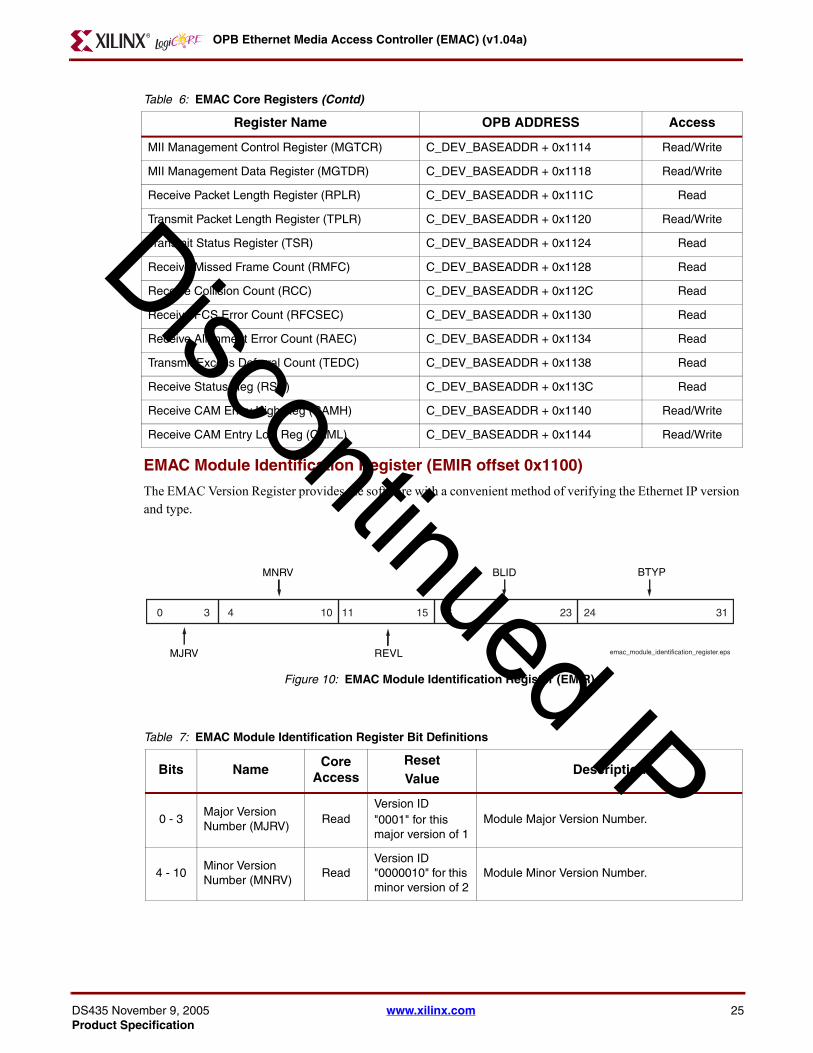
OPB Ethernet Media Access Controller (EMAC) (v104a)
DS435 NovProduct Sp
D
EMAC Module Identification Register (EMIR offset 0x1100)
The EMAC Version Register provides the software with a convenient method of verifying the Ethernet IP version and type
Figure 10 EMAC Module Identification Register (EMIR)
Figure Top x-ref 10
0 3 4 10 11 15 16 23 24 31
BLID
REVL
MNRV BTYP
emac_module_identification_registerepsMJRV
MII Management Control Register (MGTCR) C_DEV_BASEADDR + 0x1114 ReadWrite
MII Management Data Register (MGTDR) C_DEV_BASEADDR + 0x1118 ReadWrite
Receive Packet Length Register (RPLR) C_DEV_BASEADDR + 0x111C Read
Transmit Packet Length Register (TPLR) C_DEV_BASEADDR + 0x1120 ReadWrite
Transmit Status Register (TSR) C_DEV_BASEADDR + 0x1124 Read
Receive Missed Frame Count (RMFC) C_DEV_BASEADDR + 0x1128 Read
Receive Collision Count (RCC) C_DEV_BASEADDR + 0x112C Read
Receive FCS Error Count (RFCSEC) C_DEV_BASEADDR + 0x1130 Read
Receive Alignment Error Count (RAEC) C_DEV_BASEADDR + 0x1134 Read
Transmit Excess Deferral Count (TEDC) C_DEV_BASEADDR + 0x1138 Read
Receive Status Reg (RSR) C_DEV_BASEADDR + 0x113C Read
Receive CAM Entry High Reg (CAMH) C_DEV_BASEADDR + 0x1140 ReadWrite
Receive CAM Entry Low Reg (CAML) C_DEV_BASEADDR + 0x1144 ReadWrite
Table 7 EMAC Module Identification Register Bit Definitions
Bits NameCore
AccessResetValue
Description
0 - 3Major Version Number (MJRV)
ReadVersion ID0001 for this major version of 1
Module Major Version Number
4 - 10Minor Version Number (MNRV)
ReadVersion ID 0000010 for this minor version of 2
Module Minor Version Number
Table 6 EMAC Core Registers (Contd)
Register Name OPB ADDRESS Access
iscontinued IP
ember 9 2005 wwwxilinxcom 25ecification
OPB Ethernet Media Access Controller (EMAC) (v104a)
26
D
EMAC Control Register (ECR offset 0x1104)
The EMAC Control Register shown in Figure 11 and described in Table 8 controls the operation of the EMAC Please note that some of these bits should not be changed while transmit and receive are enabled (ECRENTX andor ECRENRX =rsquo1rsquo)
Figure 11 EMAC Control Register (ECR)
Figure Top x-ref 11
RSTTXRSTRX
ENPHYTXFCS
TXERR ILBE RSVD MA PA RXJB IPPE CAMW Reserved
emac_control_registerepsFD ENTX
ENRXTXPAD
TXSASAOE STRP UA BA REO CAME RSVD
0 1 2 3 4 5 6 7 8 9 10 11 12 13 14 15 16 17 18 19 20 21 23 2422 31
11 -15Rev Letter (REVL)
ReadVersion ID 00000 for this revision of a
Module Minor Version Letter This is a binary encoding of small case letters a through z (00000 - 11001)
16 - 23 Block ID (BLID) Read
Assigned by Platform Generator defaults to 00000001
Block ID Number Distinct number for each EMAC instantiated by Platform Generator
24 - 31Block Type (BTYP)
Read 00000001Block Type This is an 8 bit identifier unique to each IP type For EMAC this type is hex 01
Table 7 EMAC Module Identification Register Bit Definitions (Contd)
Bits NameCore
AccessResetValue
Description
iscontinued IP
wwwxilinxcom DS435 November 9 2005Product Specification
OPB Ethernet Media Access Controller (EMAC) (v104a)
DS435 NovProduct Sp
D
Table 8 EMAC Control Register Bit Definitions
Bit(s) NameCore
AccessResetValue
Description
0 FD ReadWrite rsquo0rsquo
Full Duplex Selects either full duplex mode (ie EMAC can receive and transmit simultaneously on a dedicated Ethernet bus segment) or half duplex mode Choosing half duplex enables CSMACD mode Choosing full duplex mode disables CCSMACD mode It is the responsibility of the software to ensure that this mode matches the PHY if the PHY is operating in auto-negotiation mode This bit should not be modified while transmit and receive are enabled ECRENTX andor ECRENRX =rsquo1rsquo
bull rsquo0rsquo -Half Duplex
bull rsquo1rsquo - Full Duplex
1 RSTTX ReadWrite rsquo1rsquo
Reset Transmitter Immediately resets the transmitter circuitry regardless of its current state The transmitter circuitry will remain in reset until this bit is set to rsquo0rsquo
bull rsquo0rsquo - Normal Operation
bull rsquo1rsquo - Reset
2 ENTX ReadWrite rsquo0rsquo
Enable Transmitter The transmitter circuitry will leave the idle state and begin transmission of a packet only when this bit is rsquo1rsquo and the transmit length register is not empty Setting this bit to rsquo0rsquo will cause the transmitter to enter the idle state after completion of any packet transmission in progress (graceful halt)
bull rsquo0rsquo - Disable Transmitter
bull rsquo1rsquo- Enable Transmitter
3 RSTRX ReadWrite rsquo1rsquo
Reset Receiver Immediately resets the receiver circuitry regardless of its current state The receiver circuitry will remain in reset until this bit is set to rsquo0rsquo
bull rsquo0rsquo - Normal Operation
bull rsquo1rsquo - Reset
4 ENRX ReadWrite rsquo0rsquo
Enable Receiver The receiver circuitry will leave the idle state and begin monitoring the Ethernet bus only when this bit is rsquo1rsquo Setting this bit to rsquo0rsquo will cause the receiver to enter the idle state after completion of any packet reception in progress (graceful halt) This bit also controls the output signal PHY_rx_en
bull rsquo0rsquo - Disable Receiver
bull rsquo1rsquo- Enable Receiver
iscontinued IP
ember 9 2005 wwwxilinxcom 27ecification
OPB Ethernet Media Access Controller (EMAC) (v104a)
28
D
5 ENPHY ReadWrite rsquo1rsquo
Enable PHY This value of this bit is driven to the PHY interface PHY_rst_n signal If the external PHY supports this signal and this bit is rsquo0rsquo the PHY will reset and remain in reset until this bit is set to rsquo1rsquo PHY_rst_n will also be driven active while OPB_Rst is active regardless of value of this bit PHY_rst_n can also be driven active by writing to the Device Software Reset Register if the software reset function has been included in the build The software reset function is not dependent on the value of this bit
bull rsquo0rsquo - Disable Reset PHY
bull rsquo1rsquo- Enable PHY
6 TXPAD ReadWrite rsquo1rsquo
Enable Transmit Auto Pad Insertion Enables automatic pad field insertion by the EMAC circuitry if it is necessary When this is enabled the transmit packet data provided to the EMAC should not contain pad data When this is enabled auto FCS insertion must also be selected to insure correct FCS calculation over the pad field When this is disabled the transmit packet data provided to the EMAC should contain pad data if required This bit should not be modified while transmit and receive are enabled ECRENTX =rsquo1rsquo andor ECRENRX =rsquo1rsquo
bull rsquo0rsquo - Disable Auto Pad Insertion
bull rsquo1rsquo- Enable Auto Pad Insertion
7 TXFCS ReadWrite rsquo1rsquo
Enable Transmit Auto FCS Insertion Enables automatic FCS field insertion by the EMAC circuitry When this is enabled the transmit packet data provided to the EMAC should not contain FCS data When this is disabled the transmit packet data provided to the EMAC should contain FCS data This bit should not be modified while transmit and receive are enabled ECRENTX =rsquo1rsquo andor ECRENRX =rsquo1rsquo
bull rsquo0rsquo - Disable Auto FCS Insertion
bull rsquo1rsquo- Enable Auto FCS Insertion
8 TXSA ReadWrite rsquo1rsquo
Enable Transmit Auto Source Address Insertion Enables automatic source address field insertion from the Station Address Registers by the EMAC circuitry When this is enabled the transmit packet data provided to the EMAC should not contain source address data When this is disabled the transmit packet data provided to the EMAC should contain source address data This bit should not be modified while transmit and receive are enabled ECRENTX =rsquo1rsquo andor ECRENRX =rsquo1rsquo
bull rsquo0rsquo - Disable Auto Source Address Insertion
bull rsquo1rsquo- Enable Auto Source Address Insertion
Table 8 EMAC Control Register Bit Definitions (Contd)
Bit(s) NameCore
AccessResetValue
Description
iscontinued IP
wwwxilinxcom DS435 November 9 2005Product Specification
OPB Ethernet Media Access Controller (EMAC) (v104a)
DS435 NovProduct Sp
D
9 TXERR ReadWrite rsquo0rsquo
Transmit Error Insertion The value of this bit is driven to the PHY interface TX_ER signal If the external PHY supports this mode it will inject an error encoded byte into the transmit data when operating in 100 Base-T mode The PHY will ignore this input when operating in 10Base-T mode This bit should not be modified while transmit and receive are enabled ECRENTX =rsquo1rsquo andor ECRENRX =rsquo1rsquo
bull rsquo0rsquo - Disable Error Insertion
bull rsquo1rsquo - Enable Error Insertion
10 SAOE ReadWrite rsquo1rsquo
Source Address Overwrite Enable When set to rsquo1rsquo it enables overwriting of the source address field provided in the packet data to be transmitted The source address field is overwritten with the value contained in the SAH and SAL registers When set to rsquo0rsquo the source address field is not included in the packet data to be transmitted and the value contained in the SAH and SAL registers is inserted into the packet data stream This bit is only used when auto source address insertion is enabled ECRTXSA =rsquo1rsquo
11 ILBE ReadWrite rsquo0rsquo
Internal Loop-Back Enable Enables looping of the transmit data directly to the receive data path internally to the EMAC The transmit and receive paths are isolated from the external PHY
12 STRP ReadWrite rsquo0rsquo
Pad amp FCS Strip Enable Enables stripping of receive pad and FCS fields when typelength field is a length
bull rsquo0rsquo - Disable Strip
bull rsquo1rsquo - Enable Strip
13 Reserved Read rsquo0rsquo bull Reserved This bit is reserved for future use
14 UA ReadWrite rsquo1rsquo
Enable Unicast Address Enables the EMAC to accept valid frames that have a destination address field that matches the value in the station address registers This bit should not be modified while transmit and receive are enabled ECRENTX =rsquo1rsquo andor ECRENRX =rsquo1rsquorsquo
bull rsquo0rsquo - Disable Unicast Address
bull rsquo1rsquo - Enable Unicast Address
15 MA ReadWrite rsquo0rsquo
Enable Multicast Address Enables the EMAC to accept valid frames that have a multicast (excluding broadcast) destination address field This bit should not be modified while transmit and receive are enabled ECRENTX =rsquo1rsquo andor ECRENRX =rsquo1rsquorsquo
bull rsquo0rsquo - Disable Multicast Address
bull rsquo1rsquo - Enable Multicast Address
Table 8 EMAC Control Register Bit Definitions (Contd)
Bit(s) NameCore
AccessResetValue
Description
iscontinued IP
ember 9 2005 wwwxilinxcom 29ecification
OPB Ethernet Media Access Controller (EMAC) (v104a)
30
D
16 BA ReadWrite rsquo1rsquo
Enable Broadcast Address Enables the EMAC to accept valid frames that have a broadcast destination address field This bit should not be modified while transmit and receive are enabled ECRENTX =rsquo1rsquo andor ECRENRX =rsquo1rsquo
bull rsquo0rsquo - Disable Broadcast Address
bull rsquo1rsquo - Enable Broadcast Address
17 PA ReadWrite rsquo0rsquo
Enable Promiscuous Address Mode Enables the EMAC to accept valid frames This bit should not be modified while transmit and receive are enabled ECRENTX =rsquo1rsquo andor ECRENRX =rsquo1rsquo
bull rsquo0rsquo - Disable Promiscuous Address Mode
bull rsquo1rsquo - Enable Promiscuous Address Mode
18 REO ReadWrite rsquo0rsquo
Receive Error Override Enables the EMAC to attempt to receive and store frames even if they contain errors
bull rsquo0rsquo - Disable Error Override
bull rsquo1rsquo - Enable Error Override
19 RXJB ReadWrite 0
Receive Jumbo Frames Enable Enables the EMAC to receive jumbo size frames This bit can not be set if the jumbo functionality was not included using the parameter C_JUMBO_EXIST
bull rsquo0rsquo - Disable Rx Jumbo Frames
bull rsquo1rsquo - Enable Rx Jumbo Frames
20 CAME ReadWrite 0
Receive CAM Enable Enables the EMAC to use the 64 entry CAM for receive address validation This bit can not be set if the CAM was not included using the parameter C_CAM_EXIST
bull rsquo0rsquo - Disable Rx CAM
bull rsquo1rsquo - Enable Rx CAM
21 IPPE ReadWrite rsquo0rsquo
Interpret Pause Packets Enables the EMAC to process valid received pause packets
bull rsquo0rsquo - Disable Pause Packets
bull rsquo1rsquo - Enable Pause Packets
22 Reserved Read rsquo0rsquo Reserved These bits are reserved for future use
23 CAMW ReadWrite rsquo0rsquo
Receive CAM Write This bit Writes the contents of the CAMH and CAML registers into the CAM address also provided in CAMH This bit will automatically reset to rsquo0rsquo Setting this bit will have no effect if the CAM was not included using the parameter C_CAM_EXIST
bull rsquo0rsquo - CAM Write Idle
bull rsquo1rsquo - Initiate a CAM Write
24-31 Reserved Read 0x000 Reserved These bits are reserved for future use
Table 8 EMAC Control Register Bit Definitions (Contd)
Bit(s) NameCore
AccessResetValue
Description
iscontinued IP
wwwxilinxcom DS435 November 9 2005Product Specification
OPB Ethernet Media Access Controller (EMAC) (v104a)
DS435 NovProduct Sp
D
Interframe Gap Register (IFGP offset 0x1108)
The Interframe Gap Register shown in Figure 12 and described in Table 9 controls the duration of the interframe Gap The Interframe Gap is the sum of IFGP1 and IFGP2 measuring in units of the bit time multiplied by four Please refer to the paragraph Interframe Gap and Deferring for information about how the Interframe Gap is used by the EMAC Please note that these settings should not be changed while transmit and receive are enabled (ECRENTX andor ECRENRX =rsquo1rsquo)
Figure 12 Interframe Gap Register (IFGP)
Figure Top x-ref 12
0 4 5 9 10
IFGP2
interframe_gap_registerepsIFGP1 Reserved
Table 9 Interframe Gap Register Bit Definitions
Bit(s) NameCore
AccessResetValue
Description
0-4 IFGP1 ReadWrite 10000
Interframe Gap Part 1 A value of 1 in this field would provide a 4 bit time interframe part 1 gap to be combined with the interframe part 2 gap for the total interframe gap time The reset value for this field is value recommended for most operation by IEEE Std 8023 This field should not be modified while transmit and receive are enabled ECRENTX =rsquo1rsquo andor ECRENRX =rsquo1rsquo
5-9 IFGP2 ReadWrite 01000
Interframe Gap Part 2 A value of 1 in this field would provide a 4 bit time interframe part 2 gap to be combined with the interframe part 1 gap for the total interframe gap time The reset value for this field is value recommended for most operation by IEEE Std 8023 This field should not be modified while transmit and receive are enabled ECRENTX =rsquo1rsquo andor ECRENRX =rsquo1rsquo
10-31 Reserved Read 0x000000 Reserved These bits are reserved for future use
Receive Packet Length Register (RPLR offset 0x111C)
The receive packet length register is actually a FIFO of register values each corresponding to a valid frame received The data for the frame is stored in the receive data FIFO and the status word is stored in the receive status register FIFO
The width of this register varies based on the value of the parameter C_JUMBO_EXIST If C_JUMBO_EXIST = rsquo1rsquo bits 18 through 31 are used to store the length value where as bits 21 through 31 are used when C_JUMBO_EXIST = rsquo0rsquo
iscontinued IP
ember 9 2005 wwwxilinxcom 31ecification
OPB Ethernet Media Access Controller (EMAC) (v104a)
32
D
The data is written by the EMAC when the framersquos destination address passes the current address validation modes and when the frame has been determined to be valid and the receive data FIFO had enough locations that all of the frame data has been saved The existence of data in the receive packet length FIFO (FIFO empty flag is rsquo0rsquo) may be used to initiate the processing of received packets until this FIFO is empty The interrupt Receive Complete is set when at least one entry is stored in this FIFO from a successful packet reception An interrupt Receive Length FIFO Empty also is available Reading this register causes the current value to be removed from the FIFO The Receive Packet Length register is shown in Figure 13 and described in Table 10
Reading of this register will Flush the RX_DRE of any residue data if C_RX_DRE_TYPEgt0
Figure 13 Receive Packet Length Register (RPLR)
Figure Top x-ref 13
18 19 20 21 31
Reserved RXPL
receive_packet_length_registereps
Table 10 Receive Packet Length Register Bit Definitions
Bit(s) NameCore
AccessResetValue
Description
0-17 or
0-20Reserved Read 0x00000 Reserved These bits are reserved for future use
18-31 or
21-31RXPL Read 0x000
Receive Packet Length The number of bytes of the corresponding receive packet stored in the receive data FIFO
Transmit Packet Length Register (TPLR offset 0x1120)
The transmit packet length register is actually a FIFO of register values each corresponding to a valid frame ready for transmit The data for the frame is stored in the transmit data FIFO
The width of this register varies based on the value of the parameter C_JUMBO_EXIST If C_JUMBO_EXIST = rsquo1rsquo bits 18 through 31 are used to store the length value where as bits 21 through 31 are used when C_JUMBO_EXIST = rsquo0rsquo
The data is written to the EMAC over the external processor bus interface either by simple DMA ScatterGather DMA or by direct memory mapped access
When presenting a transmit packet to the EMAC the packet data should first be written to the transmit data FIFO The existence of data in the transmit packet length FIFO (FIFO empty flag is rsquo0rsquo) is used by the EMAC to initiate the processing of transmit packets until this FIFO is empty
The Transmit Packet Length register shown in Figure 14 and described in Table 11 can be read over the processor interface but only the EMAC can remove a value from the FIFO The EMAC will remove the current length from the FIFO when it completes the corresponding transmission If multiple reads are performed prior to that completion the same value will be returned for each read operation
iscontinued IP
wwwxilinxcom DS435 November 9 2005Product Specification
OPB Ethernet Media Access Controller (EMAC) (v104a)
DS435 NovProduct Sp
D
Writing to this register will cause an automatic Write Push to happen on the Write Packet FIFO if C_TX_DRE_TYPEgt0
Figure 14 Transmit Packet Length Register (TPLR)
Figure Top x-ref 14
18 19 20 21 31
Reserved TXPL
transmit_packet_length_registereps
Table 11 Transmit Packet Length Register Bit Definitions
Bit(s) NameCore
AccessResetValue
Description
0-17or
0-20Reserved Read 0x00000 Reserved These bits are reserved for future use
18-31 or
21-31TXPL ReadWrite 0x000
Transmit Packet Length The number of bytes of the corresponding transmit packet stored in the transmit data FIFO
Receive Status Register (RSR offset 0x113C)
The receive status register shown in Figure 15 and described in Table 12 is a place holder for the receive status register that is used by the Scatter Gather DMA interface The EMAC does not need a receive status register but is required to provide the correct value in bit 31 to the generalized Scatter Gather DMA circuitry as part of a standard receive packet operation
Note that when C_RX_INCLUDE_CSUM is true this value is written into the RDPFIFO along with the RAW checksum
Figure 15 Receive Status Register (RSR)
Figure Top x-ref 15
31
Reserved RPCF
receive_status_registereps
iscontinued IP
ember 9 2005 wwwxilinxcom 33ecification
OPB Ethernet Media Access Controller (EMAC) (v104a)
34
D
Table 12 Receive Status Register Bit Definitions
Bit(s) NameCore
AccessResetValue
Description
0 - 30 Reserved NA 0x00000000Reserved These bits are unused and will always return all zeros
31 RPCF Read rsquo1rsquo
Receive Packet Complete Flag This bit is always rsquo1rsquo and is used to indicate to the software that a buffer descriptor associated with this packet has been completely processed by the DMA circuitry and is available for software use
Transmit Status Register (TSR offset 0x1124)
The transmit status register shown in Figure 16 and described in Table 13 is actually a FIFO of register values each corresponding to a frame transmission attempt The bits in this register reflect the specific status of the corresponding transmit operation including the EMAC settings which were applied to the transmit operation Reading this register causes the current value to be removed from the FIFO
Figure 16 Transmit Status Register (TSR)
Figure Top x-ref 16
0 1 2 6 7 8 31
TXED TXA Reserved TPCF
transmit_status_registerepsRFIFOU TXLC
iscontinued IP
wwwxilinxcom DS435 November 9 2005Product Specification
OPB Ethernet Media Access Controller (EMAC) (v104a)
DS435 NovProduct Sp
D
Table 13 Transmit Status Register Bit Definitions
Bit(s) NameCore
AccessReset Value Description
0 TXED Read rsquo0rsquo
Transmit Excess Deferral Error This bit is only applicable in half-duplex mode It indicates that at least one transmit frame was not able to complete transmission due to collisions that exceed the maximum number of retries (16) This bit is cleared to rsquo0rsquo when read
bull rsquo0rsquo - No excess deferrals occurred since the last read
bull rsquo1rsquo - At least one excess deferral has occurred
1 PFIFOU Read rsquo0rsquo
Packet Fifo Underrun This bit indicates that at least one transmit frame experienced a packet FIFO underrun condition during transmission This bit is cleared to rsquo0rsquo when read
bull rsquo0rsquo - No packet FIFO underruns occurred since the last read
rsquo1rsquo - At least one packet FIFO underrun has occurred
2- 6 TXA Read 0x00
Transmission Attempts The number of transmission attempts made There will be a maximum of 16 attempts
7 TXLC Read rsquo0rsquo
Transmit Late Collision Error This bit is only applicable in half-duplex mode It indicates a non-recoverable collision occurred more than 64-bit times after the start of the transmission No automatic retransmission can be attempted by the EMAC A late collision should never occur on a compliant Ethernet network
bull rsquo0rsquo - No late collisions occurred
bull rsquo1rsquo - Late collision occurred
8 - 30 Reserved NA 0x000000Reserved These bits are unused and will always return all zeros
31 TPCF Read rsquo1rsquo
Transmit Packet Complete Flag This bit is always rsquo1rsquo and is used to indicate to the software that a buffer descriptor associated with this packet has been completely processed by the DMA circuitry and is available for software use
Station Address High Register (SAH offset 0x110C)
The station address high register shown inFigure 17 and described in Table 14 contains the high-order 16 bits of the 48 bit station address
iscontinued IP
ember 9 2005 wwwxilinxcom 35ecification
OPB Ethernet Media Access Controller (EMAC) (v104a)
36
D
Figure 17 Station Address High (SEH) Register
Figure Top x-ref 17
16 31
Reserved SAH
station_address_high_registereps
Table 14 Station Address High Register Bit Definitions
Bit(s) NameCore
AccessResetValue
Description
0-15 Reserved Read 0x0000 Reserved These bits are reserved for future use
16-31 SAH ReadWrite 0x0000Station Address High This register should not be modified while transmit and receive are enabled ECRENTX =rsquo1rsquo andor ECRENRX =rsquo1rsquo
Station Address Low Register (SAL offset 0x1110)
The station address low register shown inFigure 18 and described in Table 15 contains the low-order 32 bits of the 48 bit station address
Figure 18 Station Address Low (SAL) Register
Figure Top x-ref 18
310
SAL
station_address_low_registereps
Table 15 Station Address Low Register Bit Definitions
Bit(s) NameCore
AccessResetValue
Description
0-31 D0 - D31 ReadWrite 0x00000000
Station Address Low This register should not be modified while transmit and receive are enabled ECRENTX =rsquo1rsquo andor ECRENRX =rsquo1rsquorsquo
MII Management Control Register (MGTCR offset 0x1114)
The MII management control register shown in Figure 19 and described in Table 16 is used with the MII management data register to perform read and writes between the EMAC and the external PHY device via the MII management interface
iscontinued IP
wwwxilinxcom DS435 November 9 2005Product Specification
OPB Ethernet Media Access Controller (EMAC) (v104a)
DS435 NovProduct Sp
D
Figure 19 MII Management Control Register (MGTCR)
Figure Top x-ref 19
mii_mngmnt_control_registereps
0 1 2 6 7 11 12 13 14
SB IEPHYAD
RWN REGAD MIIRE
Reserved
Table 16 MII Management Control Register Bit Definitions
Bit(s) NameCore
AccessResetValue
Description
0 SB ReadWrite rsquo0rsquo
Start Busy writing a rsquo1rsquo to this bit initiates an MII read or write operation The EMAC will clear this bit to rsquo0rsquo when the operation has been completed
bull rsquo0rsquo - No MII Operation in Progress
bull rsquo1rsquo- MII Read or Write in Progress
1 RWN ReadWrite rsquo1rsquo
Read Write Not This bit indicates the direction of the MII operation
bull rsquo0rsquo - Write to PHY register
bull rsquo1rsquo- Read from PHY register
2-6 PHYAD ReadWrite 0x00PHY Address This field is used to specify the address of the PHY to be accessed
7-11 REGAD ReadWrite 0x00Register Address This field is used to specify the register in the PHY to be accessed
12 IE ReadWrite rsquo0rsquo
MII Management Interface Enable This bit controls the 3-state drivers for the MII management signal interface to the PHY
bull rsquo0rsquo - The MII management signals to the PHY are 3-stated
bull rsquo1rsquo - The MII management signals to the PHY are driven and controlled by the EMAC management interface
13 MIIRE Read rsquo0rsquo
MII Management Read Error Indicates that a read from a PHY register is invalid and the operation should be retried This is indicated during a read turn-around cycle when the PHY does not drive the MDIO signal to the low state This bit is cleared to rsquo0rsquo when read
bull rsquo0rsquo - No read errors occurred since the last read
bull rsquo1rsquo - At least one read error has occurred
14-31 Reserved Read 0x00000 Reserved These bits are reserved for future use
iscontinued IP
ember 9 2005 wwwxilinxcom 37ecification
OPB Ethernet Media Access Controller (EMAC) (v104a)
38
D
MII Management Data Register (MGTDR offset 0x1118)
The MII management data register shown in Figure 20 and described in Table 17 is used with the MII management control register to perform read and writes between the EMAC and the external PHY device via the MII management interface For a PHY register write operation data should be written to the data register prior to the write to the control register
Figure 20 MII Management Data Register (MGTDR)
Figure Top x-ref 20
16 31
Reserved MIID
mii_mngmnt_data_registereps
Table 17 MII Management Data Register Bit Definitions
Bit(s) NameCore
AccessResetValue
Description
0 - 15 Reserved NA 0x0000Reserved These bits are unused and will always return all zeros
16-31 MIID ReadWrite 0x0000 MII Management Data Register
Receive Missed Frame Count (RMFC offset 0x1128)
The receive missed frame count register is shown in Figure 21 and described in Table 18 This register value represents the number of missed valid frames since the last reset with destination addresses that pass the current address validation modes
Figure 21 Received Missed Frame Count (RMFC) Register
Figure Top x-ref 21
16 31
Reserved RMFC
receive_missed_frame_count_registereps
Table 18 Receive Missed Frame Count Bit Definitions
Bit(s) NameCore
AccessResetValue
Description
0 - 15 Reserved NA 0x0000Reserved These bits are unused and will always return all zeros
16-31 RMFC Read 0x0000 Receive Missed Frame Count
iscontinued IP
wwwxilinxcom DS435 November 9 2005Product Specification
OPB Ethernet Media Access Controller (EMAC) (v104a)
DS435 NovProduct Sp
D
Receive Collision Count (RCC offset 0x112C)
The receive collision count register value represents the number of received frames that were interrupt by a collision since the last reset These frames may or may not have satisfied the current address validation modes This counter is not used in full duplex mode The receive collision count register is shown in Figure 22 and described in Table 19
Figure 22 Receive Collision Count (RCC) Register
Figure Top x-ref 22
16 31
Reserved RCC
receive_collision_count_registereps
Table 19 Receive Collision Count Bit Definitions
Bit(s) NameCore
AccessResetValue
Description
0 - 15 Reserved NA 0x0000Reserved These bits are unused and will always return all zeros
16-31 RCC Read 0x0000 Receive Collision Count
Receive FCS Error Count (RFCSEC offset 0x1130)
This register value represents the number of received frames since the last reset with destination addresses that pass the current address validation modes but with FCS validation failures The RFCSEC register is shown in Figure 23 and described in Table 20
Figure 23 Receive FCS Error Count (RFCSEC) Register
Figure Top x-ref 23
16 31
Reserved RFCSEC
receive_fcs_error_count_registereps
Table 20 Receive FCS Error Count Bit Definitions
Bit(s) NameCore
AccessResetValue
Description
0 - 15 Reserved NA 0x0000Reserved These bits are unused and will always return all zeros
16-31 RFCSEC Read 0x0000 Receive FCS Error Count
iscontinued IP
ember 9 2005 wwwxilinxcom 39ecification
OPB Ethernet Media Access Controller (EMAC) (v104a)
40
D
Receive Alignment Error Count (RAEC offset 0x1134)
This register value represents the number of received frames since the last reset with an odd number of nibbles that pass the current address validation modes and FCS validation with the extra nibbles truncated The RAEC register is shown in Figure 24 and described in Table 21
Figure 24 Receive Alignment Error Count (RAEC) Register
Figure Top x-ref 24
16 31
Reserved RAEC
receive_alignment_error_count_registereps
Table 21 Receive Alignment Error Count Bit Definitions
Bit(s) NameCore
AccessResetValue
Description
0 - 15 Reserved NA 0x0000Reserved These bits are unused and will always return all zeros
16-31 RAEC Read 0x0000 Receive Alignment Error Count
Transmit Excess Deferral Count (TEDC offset 0x1138)
This register value represents the number of transmitted frames since the last reset that could not be successful transmitted in 16 attempts This counter is not used in full duplex mode The TEDC register is shown in Figure 25 and described in Table 22
Figure 25 Transmit Excess Deferral Count (TEDC) Register
Figure Top x-ref 25
16 31
Reserved TEDC
transmit_exess_deferral_count_registereps
Table 22 Transmit Excess Deferral Count Bit Definitions
Bit(s) NameCore
AccessResetValue
Description
0 - 15 Reserved NA 0x0000Reserved These bits are unused and will always return all zeros
16-31 TEDC Read 0x0000 Transmit Excess Deferral Count
iscontinued IP
wwwxilinxcom DS435 November 9 2005Product Specification
OPB Ethernet Media Access Controller (EMAC) (v104a)
DS435 NovProduct Sp
D
Receive CAM Entry High Register (CAMH offset 0x1140)
The CAMH register shown in Figure 26 and described in Table 23 exists only if the CAM in included in the design (C_CAM_EXIST = rsquo1rsquo) This register contains the address of the CAM location (0 to 63) to which a MAC address will be written along with the upper 16 bits of that MAC address (similar to the SAH register) The MAC address in this register and the CAML register will be written into the CAM at the address provided in this register when ECR bit 23 is set to rsquo1rsquo
Figure 26 Receive CAM Entry High (CAMH) Register
Figure Top x-ref 26
10 15 16 31
Reserved
receive_cam_entry_high_registereps
CAM Address MAC Address
Table 23 Receive CAM Entry High Register Bit Definitions
Bit(s) NameCore
AccessResetValue
Description
0-9 Reserved Read 0000000000 Reserved These bits are reserved for future use
10-15 CAMA ReadWrite 00000 CAM entry address (0 to 63)
16-31 MACH ReadWrite 0x0000 MAC Address High
Receive CAM Entry Low Register (SAL offset 0x1144)
The SAL register shown in Figure 27 and described in Table 24 exists only if the CAM in included in the design (C_CAM_EXIST = rsquo1rsquo) This register contains the lower 32 bits of that MAC address (similar to the SAL register) The MAC address in this register and the CAMH register will be written into the CAM at the address provided in the CAMH register when ECR bit 23 is set to rsquo1rsquo
Figure 27 Receive CAM Entry Low (CAMH) Register
Figure Top x-ref 27
310
receive_cam_entry_low_registereps
MAC Address
Table 24 Receive CAM Entry Low Register Bit Definitions
Bit(s) NameCore
AccessResetValue
Description
0-31 D0 - D31 ReadWrite 0x00000000 MAC Address Low
iscontinued IP
ember 9 2005 wwwxilinxcom 41ecification
OPB Ethernet Media Access Controller (EMAC) (v104a)
42
D
EMAC Block DiagramThe top-level block diagram for the EMAC is shown in Figure 1
Block Diagram TX Control
The block diagram for the TX Control is shown in Figure 28
Figure 28 TX Control Block Diagram
Figure Top x-ref 28
TXFIFO Registers
TX ControlState Machine
InterframeGap Counter
CollisionWindow Counter
ExcessiveDeferral Counter
tx_control_block_diagrameps
RetryCounter
BackoffCounter
LFSR16
TX CRCGenerator
TX Bus FIFO
Block Diagram RX Control
The block diagram for the RX Control is shown in Figure 29
Figure 29 RX Control Block Diagram
Figure Top x-ref 29
RXFIFO Registers
RX ControlState Machine
AddressVaiidation
FCSError Counter
CollisionError Counter
rx_control_block_diagrameps
MissedFrame Counter
ByteCounter
RX CRCGenerator
RX Bus FIFO
EMAC ClocksThe EMAC design has four clock domains that are all asynchronous to each other These clock domains and any special requirements regarding them are discussed below
iscontinued IP
wwwxilinxcom DS435 November 9 2005Product Specification
OPB Ethernet Media Access Controller (EMAC) (v104a)
DS435 NovProduct Sp
D
Transmit Clock (PHY_tx_clk)
The transmit clock [PHY_tx_clk] is generated by the external PHY and must be used by the EMAC to provide transmit data [PHY_tx_data (30)] and control signals [PHY_tx_en and PHY_tx_er] to the PHY The PHY provides one clock cycle for each nibble of data transferred resulting in a 25 MHz clock for 10BASE-T operation and 25 MHz for 100BASE-T operation at +- 100 ppm with a duty cycle of between 35 and 65 inclusive The PHY derives this clock from an external oscillator or crystal
Receive Clock (PHY_rx_clk)
The receive clock [PHY_rx_clk] is also generated by the external PHY but is derived from the incoming Ethernet traffic Like the transmit clock the PHY provides one clock cycle for each nibble of data transferred resulting in a 25 MHz clock for 10BASE-T operation and 25 MHz for 100BASE-T operation with a duty cycle of between 35 and 65 inclusive while incoming data is valid [PHY_dv is rsquo1rsquo]
The minimum high and low times of the receive clock are at least 35 of the nominal period under all conditions The receive clock is used by the EMAC to sample the receive data [PHY_rx_data(30)] and control signals [PHY_dv and PHY_rx_er] from the PHY
MII Management Clock (PHY_mii_clk)
The Management Data Clock (PHY_mii_clk) is driven by the EMAC to the PHY as the reference for data transfer on the PHY_mii_data signal This signal has no maximum high and low times and need not be periodic but must have a minimum high and low time of at least 160 nS with a corresponding minimum period of 400 nS (corresponds to a maximum of 25 MHz) The MII clock will be a divide by 64 from the OPB bus clock for OPB bus frequencies of 65 to 150 MHz range resulting in a PHY_mii_clk of approximately 1 to 23 MHz
Processor Bus Clock (OPB_Clk)
The majority of the EMAC operation functions in the processor bus clock domain This clock must be greater than to equal to 65 MHz in order to transmit and receive Ethernet data at 100 Mbs and greater than to equal to 65 MHz in order to transmit and receive Ethernet data at 10 Mbs
PHY Interface Signals
PHY_rst_n
Some PHYs use a reset input to establish or re-establish a known initial state The EMAC provides the PHY reset signal (PHY_rst_n) for this purpose This active low output is driven active when OPB_Rst is active when the EMAC Control Register bit 5 is rsquo0rsquo or when a soft reset is performed by writing to the Device Software Reset Register (offset 0x0040) when the software reset function is included in the build (C_RESET_PRESENT = rsquo1rsquo)
PHY_tx_en
The EMAC uses the Transmit Enable signal (PHY_tx_en) to indicate to the PHY that it is providing nibbles at the MII interface for transmission It is asserted synchronously to PHY_tx_clk with the first nibble of the preamble and remains asserted while all nibbles have been transmitted PHY_tx_en is negated prior to the first PHY_tx_clk following the final nibble of a frame
This signal is transferred between the PHY_tx_clk and processor clock domains at the asynchronous TX bus FIFO interface The clock to output delay of this signal must be 0 to 25 nS Figure 30 shows PHY_tx_en timing during a transmission with no collisions
iscontinued IP
ember 9 2005 wwwxilinxcom 43ecification
OPB Ethernet Media Access Controller (EMAC) (v104a)
44
D
PHY_rx_en
The EMAC uses the Receive Enable signal (PHY_rx_en) to indicate to the PHY that the PHY should pass or block receive ethernet data The value of this signal is controlled by the EMAC control register (ECR) bit 4 This signal is not used by many PHY devices
Figure 30 Transmission with no collision
Figure Top x-ref 30
transmission_with_no_collisioneps
PHY_tx_clkPHY_tx_en
PHY_tx_data[30]
PHY_cr5
PHY_col
0ns 50ns 100ns 150ns
0 Preamble SFD D0 D1 CRC 0
PHY_tx_data(30)
The EMAC drives the Transmit Data bus [PHY_tx_data(30)] synchronously to PHY_tx_clk PHY_tx_data(0) is the least significant bit The PHY will transmit the value of PHY_tx_data on every clock cycle that PHY_tx_en is asserted This bus is transferred between the PHY_tx_clk and processor clock domains at the asynchronous TX bus FIFO interface
The clock to output delay of this signal must be 0 to 25 nS The order of the bits nibbles and bytes for transmit and receive are shown in Figure 31
Figure 31 ByteNibble Transmit and Receive Order
Figure Top x-ref 31
Serial Bit StreamFirst bit
D4 D5 D6 D7LSB MST
LSB
MSB
D0
D1
D2
D3
D0 D1 D2 D3
Second nibbleFirst nibble
byte_nibble_transmit_receive_ordereps
PHY_tx_er
The EMAC drives the Transmit coding Error signal (PHY_tx_er) synchronously to PHY_tx_clk When PHY_tx_er is asserted for one or more PHY_tx_clk periods while PHY_tx_en is also asserted and the PHY is operating in 100Mbs mode the PHY transmits one or more symbols that are not part of the valid data or delimiter set somewhere in the frame being transmitted
PHY_tx_er has no effect on PHY operation in 10Mbs mode or when PHY_tx_en is de-asserted This signal is transferred between the PHY_tx_clk and processor clock domains at the asynchronous TX bus FIFO interface
iscontinued IP
wwwxilinxcom DS435 November 9 2005Product Specification
OPB Ethernet Media Access Controller (EMAC) (v104a)
DS435 NovProduct Sp
D
The clock to output delay of this signal must be 0 to 25 nS Table 25 shows the possible combinations for the transmit signals
Table 25 Possible values for PHY_tx_en PHY_tx_er PHY_tx_data[30]
PHY_tx_en PHY_tx_er PHY_tx_data[30] Indication
0 0 0000 through 1111 Normal interframe
0 1 0000 through 1111 Reserved
1 0 0000 through 1111 Normal data transmission
1 1 0000 through 1111 Transmit propagation
PHY_dv
The PHY drives the Receive Data Valid (PHY_dv) signal to indicate that the PHY is driving recovered and decoded nibbles on the PHY_rx_data(30) bus and that the data on PHY_rx_data(30) is synchronous to PHY_rx_clk PHY_dv is driven synchronously to PHY_rx_clk
PHY_dv remains asserted continuously from the first recovered nibble of the frame through the final recovered nibble and is negated prior to the first PHY_rx_clk that follows the final nibble In order for a received frame to be correctly received by the EMAC PHY_dv must encompass the frame starting no later than the Start Frame Delimiter (SFD) and excluding any End-of-Frame delimiter
This signal is transferred between the PHY_rx_clk and processor clock domains at the asynchronous RX bus FIFO interface The PHY will provide a minimum of 10 nS setup and hold time for this signal in reference to PHY_rx_clk Figure 32 shows the behavior of PHY_dv during frame reception
Figure 32 Receive With No Errors
Figure Top x-ref 32
PHY_rx_clk
PHY_dvPHY_rx_er
PHY_rx_data[30] preamble SFD D0 D1 D2 D3 CRC
receive_with_no_errorseps
PHY_rx_data(30)
The PHY drives the Receive Data bus [PHY_rx_data(30)] synchronously to PHY_rx_clk PHY_rx_data(30) contains recovered data for each PHY_rx_clk period in which PHY_dv is asserted PHY_rx_data(0) is the least significant bit The EMAC must not be affected by PHY_rx_data(30) while PHY_dv is de-asserted
Also the EMAC should ignore a special condition that occurs while PHY_dv is de-asserted when the PHY may provide a False Carrier indication by asserting the PHY_rx_er signal while driving the value lt1110gt onto PHY_rx_datalt30gt This bus is transferred between the PHY_rx_clk and processor clock domains at the asynchronous RX bus FIFO interface The PHY will provide a minimum of 10 nS setup and hold time for this signal in reference to RX_CLK
iscontinued IP
ember 9 2005 wwwxilinxcom 45ecification
OPB Ethernet Media Access Controller (EMAC) (v104a)
46
D
PHY_rx_er
The PHY drives the Receive Error signal (PHY_rx_er) synchronously to PHY_rx_clk The PHY drives PHY_rx_er for one or more PHY_rx_clk periods to indicate that an error (eg a coding error or any error that the PHY is capable of detecting) was detected somewhere in the frame presently being transferred from the PHY to the EMAC
PHY_rx_er should have no effect on the EMAC while PHY_dv is de-asserted This signal is transferred between the PHY_rx_clk and processor clock domains at the asynchronous RX bus FIFO interface The PHY will provide a minimum of 10 nS setup and hold time for this signal in reference to PHY_rx_clk Figure 33 shows the behavior of PHY_rx_er during frame reception with errors
Figure 33 Receive With Errors
Figure Top x-ref 33
PHY_rx_clk
PHY_dv
PHY_rx_er
PHY_rx_data[30] SFD D0 D1 xx CRCpreamble D3
receive_with_errorseps
Table 26 shows the possible combinations for the receive signals
Table 26 Possible values for PHY_dv PHY_rx_er and PHY_rx_data[30]
PHY_dv PHY_rx_er PHY_rx_data[30] Indication
0 0 0000 through 1111 Normal interframe
0 1 0000 Normal interframe
0 1 0000 through 1101 Reserved
0 1 1110 False carrier indication
0 1 1111 Reserved
1 0 0000 through 1111 Normal data reception
1 1 0000 through 1111 Data reception with errors
PHY_crs
The PHY drives the Carrier Sense signal (PHY_crs) active to indicate that either the transmit or receive is nonidle when operating in half duplex mode PHY_crs is de-asserted when both the transmit and receive are idle
The PHY drives PHY_crs asserted throughout the duration of a collision condition PHY_crs is not synchronous to either the PHY_tx_clk or the PHY_rx_clk The PHY_crs signal is not used in full duplex mode The PHY_crs signal is used by both the EMAC transmit and receive circuitry and is double synchronized to the processor clock as it enters the EMAC
iscontinued IP
wwwxilinxcom DS435 November 9 2005Product Specification
OPB Ethernet Media Access Controller (EMAC) (v104a)
DS435 NovProduct Sp
D
PHY_col
The PHY drives the Collision detected signal (PHY_col) active to indicate the detection of a collision on the bus The PHY drives PHY_col asserted while the collision condition persists The PHY also drives PHY_col asserted when operating at 10 Mbs for signal_quality_error (SQE) testing
PHY_col is not synchronous to either the PHY_tx_clk or the PHY_rx_clk The PHY_col signal is not used in full duplex mode The PHY_col signal is used by both the EMAC transmit and receive circuitry and is double synchronized to the processor clock as it enters the EMAC Figure 34 shows the behavior of PHY_col during frame transmission with a collision
Figure 34 Transmission With Collision
Figure Top x-ref 34
PHY_tx_clk
PHY_tx_en
PHY_tx_data[30]
PHY_crs
PHY_col
Preamble JAM 00
transmission_with_collisioneps
PHY_mii_data
The Management Data InputOutput signal (PHY_mii_data) is a bidirectional signal between the PHY and the EMAC used to transfer control and status All transfers via the PHY_mii_data are synchronous to the PHY_mii_clk signal PHY_mii_data must be driven through 3-state pins that enable either the EMAC or the PHY to drive the signal
The necessary pull-up and pull-down resistors for this signal are defined in the IEEE Std 8023 paragraph 22442 When the EMAC drives this signal it must provide a minimum of 10nS setup and hold in reference to the PHY_mii_clk signal When the PHY drives this signal it will have a clock to output delay of 0 to 300nS
Management Frame Structure
Data transferred via the PHY_mii_data is structured as frames as shown in Table 27
Table 27 Management Frame Format
Management Frame Fields
PRE ST OP PHYAD REGAD TA DATA IDLE
Read 11 01 10 AAAAA RRRRR Z0 DDDDDDDDDDDDDDDD Z
Write 11 01 01 AAAAA RRRRR 10 DDDDDDDDDDDDDDDD Z
Idle
The IDLE condition on PHY_mii_data is a high-impedance state All 3-state drivers are disabled and the PHYrsquos pull-up resistor will pull the PHY_mii_data line to a logic one
iscontinued IP
ember 9 2005 wwwxilinxcom 47ecification
OPB Ethernet Media Access Controller (EMAC) (v104a)
48
D
Preamble (PRE)
At the beginning of each management transaction the EMAC will transmit 32 contiguous logic one bits on the PHY_mii_data signal
Start of Frame (ST)
The EMAC follows the preamble with the start of frame pattern which is 01
Operation Code (OP)
The operation code is by the EMAC following the start of frame to indicate a read or write transaction A read is designated by 10 and a write by 01
PHY Address (PHYAD)
The next field transmitted by the EMAC is the 5 bit PHY address field This identifies one of up to 32 PHYs connection to the same interface The most significant bit of the address is transmitted first The special PHY address 00000 will address any PHY
Register Address (REGAD)
The EMAC follows the PHY address field with the transmission of the 5 bit register address field allowing the access of up to 32 PHY registers The most significant bit of the address is transmitted first
Turn Around (TA)
A turn around period of 2 bit times follows the register field and precedes the data field to prevent contention during a read cycle For a read both the EMAC and the PHY remain in a high-impedance state for the first bit time of the turnaround The PHY will drive a zero bit during the second bit time of the turnaround of a read transaction
During a write the EMAC must drive a one bit for the first bit time of the turnaround and a zero bit for the second bit time of the turnaround Figure 35 shows the behavior of the PHY_mii_data signal during the turnaround field of a read transaction
Figure 35 MDIO Read Turn Around
Figure Top x-ref 35
mdio_read_turnaroundeps
MDC
MDIO
0ZR
Data
The data field is 16 bits and is transmitted and received with bit 15 (MSb) first of the register being addressed
Packet FIFO InterfaceThe EMAC uses the special Mark Release and Restore features of the packet FIFOs to assist in management of transmit and receive data under special circumstances
The use of these features are discussed here as it applies to Ethernet operation Also discussed are special considerations required to support a multi-cycle dead FIFO access time following a Mark Release and Restore operation
iscontinued IP
wwwxilinxcom DS435 November 9 2005Product Specification
OPB Ethernet Media Access Controller (EMAC) (v104a)
DS435 NovProduct Sp
D
Transmit Packet FIFO Interface
The use of the special FIFO features greatly simplifies the retransmission of a packet following a collision on a half duplex bus (the features are not needed for full duplex operation) When the EMAC is ready to transmit (transmit enable is rsquo1rsquo and the transmit length register is not empty) and it is in half-duplex mode and it is not deferring it will perform a Mark in the transmit FIFO and begin reading transmit data (after a several cycle delay required by the FIFO) while counting down the length value
If no collision occurs after 64 byte times the EMAC will perform a Release to allow the FIFO locations containing the first parts of the transmit to be reused Since the EMAC will not be able to read during the several cycles following the release it will have to insure that the transmit bus FIFO contains enough nibbles to sustain continuous transmission flow until packet FIFO reads can be resumed
If a collision does occur in the first 64 byte times the EMAC will transmit the JAM pattern increment the retry count and if retries are less than 16 perform backoff and a Restore on the packet FIFO Since the EMAC will be performing backoff and deferral it will not need to access the FIFO during the Dead FIFO access time following the Restore
If a transmission was attempted 16 retries and was unsuccessful the EMAC will perform a Release and flush the remainder of the failed packet data from the transmit packet FIFO by performing the number of reads required to decrement the length counter to zero
Receive Packet FIFO Interface
The use of the special FIFO features greatly simplifies the flushing of a packet following a receive error When the EMAC detects that a packet is being received the EMAC will perform a Mark on the receive packet FIFO and begin storing receive data (after a several cycle delay required by the FIFO) while counting up the length value
The EMAC will continue reception and will store data into the receive FIFO until either the reception is successful a receive error occurs or the receive packet FIFO becomes full and overruns
Following the completion of a successful receive the EMAC will perform a Release However if an error occurs during reception or if the receive packet FIFO becomes full and overruns the EMAC will discontinue data storage into the receive packet FIFO and will flush all packet data stored there associated with the bad packet by performing a Restore There should be not be a need for special handling of the dead FIFO access time for Restore operations
When RX checksum offloading is included in the design then the Release signal will also mark the end of packet and cause the RAW checksum and RX status to be written into the FIFO This will eventually be read out of the FIFO by the DMA and put in the SR field of the RX buffer descriptor
Receive Address ValidationDestination addresses are classified as either unicast (a single station address indicated by the IG bit =rsquo0rsquo) multicast (a group of stations indicated by the IG bit =rsquo1rsquo) and the multicast subgroup broadcast (all stations on the network)
The EMAC provides flexibility for enabling each of these modes as well as a promiscuous address mode where it accepts all addresses The flow chart in Figure 36 shows the address validation process
iscontinued IP
ember 9 2005 wwwxilinxcom 49ecification
OPB Ethernet Media Access Controller (EMAC) (v104a)
50
D
Figure 36 Address Validation Process
Figure Top x-ref 36
BroadcastAddress
Multicast allEnabled
CAM Existsamp Enabled
BroadcastEnabled
UnicastEnabled
AddressValid
PauseEnabled
PromiscuousEnabled
PauseMulticast
Addr
=SAH amp SAL
=1 0f 64 CAM
Entries
MulticastAddress
TT
T T T
(16)1(17)1(15)1(20)1 (14)1 (21)1
OR
TT
T T T
T
Check Address
Notes
1 The number in parenthesis indicates bit in ECR
receive_addr_validationeps
Using the CAM for Receive Address Validation
In order to use the CAM for receive address validation it must be included in the design by setting the C_CAM_EXIST parameter = rsquo1rsquo The parameter C_CAM_BRAM_0_SRL_1 is set to select between BRAM or SRL logic based implementation This is strictly a trade off between using BRAMS or FPGA logic
The CAM is capable of holding up to 64 48 bit MAC addresses The CAM can not be read or reset To clear the CAM each of the 64 entries must be written
To write an entry to the CAM place the upper 16 bits of the MAC address in bits 16 through 31 of the CAMH register along with the CAM entry address in bits 10 through 15 The address should be in the range 0 to 63 inclusive The lower 32 bits of the MAC address must be placed in the CAML register
The write to the CAM is initiated by writing a rsquo1rsquo to bit 23 of the ECR This bit will automatically reset to rsquo0rsquo
Once all of the entries have been placed in the CAM the CAM must be enabled by writing a rsquo1rsquo to bit 20 of the ECR
iscontinued IP
wwwxilinxcom DS435 November 9 2005Product Specification
OPB Ethernet Media Access Controller (EMAC) (v104a)
DS435 NovProduct Sp
D
Error Handling
Transmit Errors
Transmit errors detected by the EMAC circuitry are noted in the transmit status word and with interrupts and an error counter for maximum software implementation flexibility
Receive Errors
The IEEE Std 8023 prevents packets with error conditions from being passed to the software interface The EMAC circuitry does provide interrupts status register bits and error counters to allow the software to monitor receive error conditions When a received frame is detected to have an error the data is discarded by using the packet FIFO mark and restore features No receive status word or length is stored for that frame
MII Management Errors
The MII Management interface will detect and indicate that a read from a PHY register is invalid and the operation should be retried when the PHY does not drive the PHY_mii_data signal to the low state during a read turn-around cycle This error condition is flagged in the MII management control register
Design ConstraintsThe Ethernet Core requires design constraints to guarantee performance These constraints should be placed in a UCF file for the top level of the design The following example of the constraint text is based on the port names of the Ethernet core If these ports are mapped to FPGA pin names that are different the FPGA pin names should be substituted for the port names in the example below
NET phy_rx_clk TNM_NET = RXCLK_GRP
NET phy_tx_clk TNM_NET = TXCLK_GRP
TIMESPEC TSTXOUT = FROM TXCLK_GRP TO PADS 10 ns
TIMESPEC TSRXIN = FROM PADS TO RXCLK_GRP 6 ns
NET opb_rst TIG
NET phy_rx_clk USELOWSKEWLINES1
NET phy_tx_clk USELOWSKEWLINES1
NET phy_tx_clk MAXSKEW= 20 ns2
NET phy_rx_clk MAXSKEW= 20 ns2
NET phy_tx_clk MAXSKEW= 10 ns3
NET phy_rx_clk MAXSKEW= 10 ns3
NET phy_rx_clk PERIOD = 40 ns HIGH 14 ns
NET phy_tx_clk PERIOD = 40 ns HIGH 14 ns
NET phy_rx_datalt3gt NODELAY2
1 Should be used only for Virtex Virtex-E Spartan-II or Spartan-IIE devices2 Should be used for all devices except Virtex-43 Should be used only for Virtex-4
iscontinued IP
ember 9 2005 wwwxilinxcom 51ecification
OPB Ethernet Media Access Controller (EMAC) (v104a)
52
C_I
PIF
_WR
FIF
O_D
EP
TH
1638
D
NET phy_rx_datalt2gt NODELAY2
NET phy_rx_datalt1gt NODELAY2
NET phy_rx_datalt0gt NODELAY2
NET phy_dv NODELAY2
NET phy_rx_er NODELAY2
NET phy_crs NODELAY2
NET phy_col NODELAY2
NET phy_rx_datalt3gt IOBDELAY=NONE3
NET phy_rx_datalt2gt IOBDELAY=NONE3
NET phy_rx_datalt1gt IOBDELAY=NONE3
NET phy_rx_datalt0gt IOBDELAY=NONE3
NET phy_dv IOBDELAY=NONE3
NET phy_rx_er IOBDELAY=NONE3
NET phy_crs IOBDELAY=NONE3
NET phy_col IOBDELAY=NONE3
Design Implementation
Device Utilization and Performance Benchmarks
Since the EMAC is a module that will be used with other design pieces in the FPGA the utilization and timing numbers reported in this section are just estimates As the EMAC is combined with other pieces of the FPGA design the utilization of FPGA resources and timing of the EMAC design will vary from the results reported here
In order to analyze the EMACrsquos timing within the FPGA a design will be created that instantiates the EMAC with the following parameters set
The EMAC benchmarks are shown in Table 28 for a Virtex-II Pro -7
Table 28 EMAC FPGA Performance and Resource Utilization Benchmarks (Virtex-II Pro -7)
Parameter Values Device Resources
C_I
PIF
_RD
FIF
O_D
EP
TH
C_D
EV
_MIR
_EN
AB
LE
C_D
MA
_PR
ES
EN
T
C_R
ES
ET
_PR
ES
EN
T
C_I
NC
LUD
E_D
EV
_PE
NC
OD
ER
C_C
AM
_BR
AM
_0_S
RL_
1
C_C
AM
_EX
IST
C_J
UM
BO
_EX
IST
C_M
AC
_FIF
O_B
RA
M_1
_SR
L_0
C_M
AC
_FIF
O_D
EP
TH
C_H
ALF
_DU
PLE
X_E
XIS
T
C_T
XR
X_D
RE
_TY
PE
C_T
XR
X_I
NC
LUD
E_C
SU
M
SlicesSlice Flip- Flops
BRAMS4-
input LUTs
fMAX
(MHz)
4 16384 0 1 0 0 0 0 0 1 16 0 0 1474 1538 5 1960 143
iscontinued IP
wwwxilinxcom DS435 November 9 2005Product Specification
OPB Ethernet Media Access Controller (EMAC) (v104a)
DS435 NovProduct Sp
1638
1638
1638
1638
1638
1638
1638
1638
1638
1638
1638
1638
3276
6553
1310
2621
2621
2621
2621
2621
2621
2621
2621
2621
3276
Notes1 I1
peres
2 Ple
D
Specification Exceptions The EMAC design currently has no exceptions to the mandatory IEEE Std 8023 MII interface requirements
Reference DocumentsThe following document contains reference information important to understanding the EMAC design
bull IEEE Std 8023
bull OPB_IPIF_V2_00_l
4 16384 0 1 0 0 0 0 0 0 16 0 0 1499 1556 2 1992 143
4 16384 0 1 0 0 0 0 0 1 16 1 0 0 1615 1706 5 2165 143
4 16384 0 1 0 1 0 0 0 1 16 1 0 0 1620 1705 5 2173 143
4 16384 0 1 1 1 0 0 0 1 16 1 0 0 1640 1715 5 2192 143
4 16384 1 1 1 1 0 0 0 1 16 1 0 0 1653 1719 5 2211 143
4 16384 1 1 1 1 0 0 0 1 32 1 0 0 1670 1722 5 2247 143
4 16384 1 1 1 1 0 0 0 0 32 1 0 0 1697 1740 2 2280 143
4 16384 1 1 1 1 0 0 0 0 64 1 0 0 1728 1743 2 2343 143
4 16384 1 1 1 1 0 0 0 1 64 1 0 0 1702 1725 5 2310 143
4 16384 1 1 1 1 0 0 1 1 64 1 0 0 1722 1741 5 2346 143
4 16384 1 1 1 1 0 1 1 1 64 1 0 0 2143 1997 17 2961 142
4 16384 1 1 1 1 1 1 1 1 64 1 0 0 2382 1934 5 3418 129
8 16384 1 1 1 1 0 1 1 1 64 1 0 0 2382 2004 18 2980 143
6 16384 1 1 1 1 0 1 1 1 64 1 0 0 2152 2012 20 1981 136
72 16384 1 1 1 1 0 1 1 1 64 1 0 0 2158 2017 24 2988 113
44 16384 1 1 1 1 0 1 1 1 64 1 0 0 2165 2023 32 3006 143
44 262144 1 1 1 1 0 1 1 1 64 1 0 0 2186 2047 47 3033 143
44 262144 1 2 1 1 0 1 1 1 64 1 0 0 3073 2706 47 4469 115
44 262144 1 3 1 1 0 1 1 1 64 1 0 0 3459 2873 47 5129 123
44 262144 1 3 1 1 1 1 1 0 64 1 0 0 3739 2832 32 5631 122
44 262144 1 3 1 1 0 1 1 1 64 1 1 0 3576 3016 47 5337 114
44 262144 1 3 1 1 1 1 1 0 64 1 1 0 3857 2977 32 5839 116
44 262144 1 3 1 1 0 1 1 1 64 1 0 1 3781 3237 47 5655 119
44 262144 1 3 1 1 1 1 1 0 64 1 0 1 4021 3198 32 6157 126
8 32768 1 3 1 1 1 0 1 1 64 1 1 0 3125 2725 7 4640 135
94 with overall effort level of high and synthesis resource sharing on into a xc2vp20-7-ff1152 device with opb_clk riod constrained to 7 nS (1428 Mhz) Turning resource sharing off in XST may increase fMAX but also may increase ources used Using -Timing based Map may also increase fMAXase refer to Table 1 for a definition of these parameters
Table 28 EMAC FPGA Performance and Resource Utilization Benchmarks (Virtex-II Pro -7) (Contd)
iscontinued IP
ember 9 2005 wwwxilinxcom 53ecification
OPB Ethernet Media Access Controller (EMAC) (v104a)
54
D
bull DMA_SG_V1_04_b
Revision History
Date Version Revision
12604 11 Initial Xilinx release
21605 12Converted to new DS template updated figures to Xilinx graphic standards reformatted tables incorporated CR198497
iscontinued IP
wwwxilinxcom DS435 November 9 2005Product Specification
- OPB Ethernet Media Access Controller (EMAC) (v104a)
-
- Introduction
- Features
- Evaluation Version
- Functional Description
- EMAC Endianess
- Ethernet Protocol
- EMAC Design Parameters
- Allowable Parameter Combinations
- Detailed Parameter Descriptions
- EMAC IO Signals
- EMAC Port Dependencies
- EMAC Interrupt Interface
- Detailed Interrupt Descriptions
- EMAC Register Definition
- EMAC IPIF Registers
- EMAC Core Registers
- EMAC Module Identification Register (EMIR offset 0x1100)
- EMAC Control Register (ECR offset 0x1104)
- Interframe Gap Register (IFGP offset 0x1108)
- Receive Packet Length Register (RPLR offset 0x111C)
- Transmit Packet Length Register (TPLR offset 0x1120)
- Receive Status Register (RSR offset 0x113C)
- Transmit Status Register (TSR offset 0x1124)
- Station Address High Register (SAH offset 0x110C)
- Station Address Low Register (SAL offset 0x1110)
- MII Management Control Register (MGTCR offset 0x1114)
- MII Management Data Register (MGTDR offset 0x1118)
- Receive Missed Frame Count (RMFC offset 0x1128)
- Receive Collision Count (RCC offset 0x112C)
- Receive FCS Error Count (RFCSEC offset 0x1130)
- Receive Alignment Error Count (RAEC offset 0x1134)
- Transmit Excess Deferral Count (TEDC offset 0x1138)
- Receive CAM Entry High Register (CAMH offset 0x1140)
- Receive CAM Entry Low Register (SAL offset 0x1144)
- EMAC Block Diagram
- EMAC Clocks
- Transmit Clock (PHY_tx_clk)
- Receive Clock (PHY_rx_clk)
- MII Management Clock (PHY_mii_clk)
- Processor Bus Clock (OPB_Clk)
- PHY Interface Signals
- PHY_rst_n
- PHY_tx_en
- PHY_rx_en
- PHY_tx_data(30)
- PHY_tx_er
- PHY_dv
- PHY_rx_data(30)
- PHY_rx_er
- PHY_crs
- PHY_col
- PHY_mii_data
- Packet FIFO Interface
- Transmit Packet FIFO Interface
- Receive Packet FIFO Interface
- Receive Address Validation
- Using the CAM for Receive Address Validation
- Error Handling
- Transmit Errors
- Receive Errors
- MII Management Errors
- Design Constraints
- Design Implementation
- Device Utilization and Performance Benchmarks
- Specification Exceptions
- Reference Documents
- Revision History
-

OPB Ethernet Media Access Controller (EMAC) (v104a)
DS435 NovProduct Sp
D
Table 8 EMAC Control Register Bit Definitions
Bit(s) NameCore
AccessResetValue
Description
0 FD ReadWrite rsquo0rsquo
Full Duplex Selects either full duplex mode (ie EMAC can receive and transmit simultaneously on a dedicated Ethernet bus segment) or half duplex mode Choosing half duplex enables CSMACD mode Choosing full duplex mode disables CCSMACD mode It is the responsibility of the software to ensure that this mode matches the PHY if the PHY is operating in auto-negotiation mode This bit should not be modified while transmit and receive are enabled ECRENTX andor ECRENRX =rsquo1rsquo
bull rsquo0rsquo -Half Duplex
bull rsquo1rsquo - Full Duplex
1 RSTTX ReadWrite rsquo1rsquo
Reset Transmitter Immediately resets the transmitter circuitry regardless of its current state The transmitter circuitry will remain in reset until this bit is set to rsquo0rsquo
bull rsquo0rsquo - Normal Operation
bull rsquo1rsquo - Reset
2 ENTX ReadWrite rsquo0rsquo
Enable Transmitter The transmitter circuitry will leave the idle state and begin transmission of a packet only when this bit is rsquo1rsquo and the transmit length register is not empty Setting this bit to rsquo0rsquo will cause the transmitter to enter the idle state after completion of any packet transmission in progress (graceful halt)
bull rsquo0rsquo - Disable Transmitter
bull rsquo1rsquo- Enable Transmitter
3 RSTRX ReadWrite rsquo1rsquo
Reset Receiver Immediately resets the receiver circuitry regardless of its current state The receiver circuitry will remain in reset until this bit is set to rsquo0rsquo
bull rsquo0rsquo - Normal Operation
bull rsquo1rsquo - Reset
4 ENRX ReadWrite rsquo0rsquo
Enable Receiver The receiver circuitry will leave the idle state and begin monitoring the Ethernet bus only when this bit is rsquo1rsquo Setting this bit to rsquo0rsquo will cause the receiver to enter the idle state after completion of any packet reception in progress (graceful halt) This bit also controls the output signal PHY_rx_en
bull rsquo0rsquo - Disable Receiver
bull rsquo1rsquo- Enable Receiver
iscontinued IP
ember 9 2005 wwwxilinxcom 27ecification
OPB Ethernet Media Access Controller (EMAC) (v104a)
28
D
5 ENPHY ReadWrite rsquo1rsquo
Enable PHY This value of this bit is driven to the PHY interface PHY_rst_n signal If the external PHY supports this signal and this bit is rsquo0rsquo the PHY will reset and remain in reset until this bit is set to rsquo1rsquo PHY_rst_n will also be driven active while OPB_Rst is active regardless of value of this bit PHY_rst_n can also be driven active by writing to the Device Software Reset Register if the software reset function has been included in the build The software reset function is not dependent on the value of this bit
bull rsquo0rsquo - Disable Reset PHY
bull rsquo1rsquo- Enable PHY
6 TXPAD ReadWrite rsquo1rsquo
Enable Transmit Auto Pad Insertion Enables automatic pad field insertion by the EMAC circuitry if it is necessary When this is enabled the transmit packet data provided to the EMAC should not contain pad data When this is enabled auto FCS insertion must also be selected to insure correct FCS calculation over the pad field When this is disabled the transmit packet data provided to the EMAC should contain pad data if required This bit should not be modified while transmit and receive are enabled ECRENTX =rsquo1rsquo andor ECRENRX =rsquo1rsquo
bull rsquo0rsquo - Disable Auto Pad Insertion
bull rsquo1rsquo- Enable Auto Pad Insertion
7 TXFCS ReadWrite rsquo1rsquo
Enable Transmit Auto FCS Insertion Enables automatic FCS field insertion by the EMAC circuitry When this is enabled the transmit packet data provided to the EMAC should not contain FCS data When this is disabled the transmit packet data provided to the EMAC should contain FCS data This bit should not be modified while transmit and receive are enabled ECRENTX =rsquo1rsquo andor ECRENRX =rsquo1rsquo
bull rsquo0rsquo - Disable Auto FCS Insertion
bull rsquo1rsquo- Enable Auto FCS Insertion
8 TXSA ReadWrite rsquo1rsquo
Enable Transmit Auto Source Address Insertion Enables automatic source address field insertion from the Station Address Registers by the EMAC circuitry When this is enabled the transmit packet data provided to the EMAC should not contain source address data When this is disabled the transmit packet data provided to the EMAC should contain source address data This bit should not be modified while transmit and receive are enabled ECRENTX =rsquo1rsquo andor ECRENRX =rsquo1rsquo
bull rsquo0rsquo - Disable Auto Source Address Insertion
bull rsquo1rsquo- Enable Auto Source Address Insertion
Table 8 EMAC Control Register Bit Definitions (Contd)
Bit(s) NameCore
AccessResetValue
Description
iscontinued IP
wwwxilinxcom DS435 November 9 2005Product Specification
OPB Ethernet Media Access Controller (EMAC) (v104a)
DS435 NovProduct Sp
D
9 TXERR ReadWrite rsquo0rsquo
Transmit Error Insertion The value of this bit is driven to the PHY interface TX_ER signal If the external PHY supports this mode it will inject an error encoded byte into the transmit data when operating in 100 Base-T mode The PHY will ignore this input when operating in 10Base-T mode This bit should not be modified while transmit and receive are enabled ECRENTX =rsquo1rsquo andor ECRENRX =rsquo1rsquo
bull rsquo0rsquo - Disable Error Insertion
bull rsquo1rsquo - Enable Error Insertion
10 SAOE ReadWrite rsquo1rsquo
Source Address Overwrite Enable When set to rsquo1rsquo it enables overwriting of the source address field provided in the packet data to be transmitted The source address field is overwritten with the value contained in the SAH and SAL registers When set to rsquo0rsquo the source address field is not included in the packet data to be transmitted and the value contained in the SAH and SAL registers is inserted into the packet data stream This bit is only used when auto source address insertion is enabled ECRTXSA =rsquo1rsquo
11 ILBE ReadWrite rsquo0rsquo
Internal Loop-Back Enable Enables looping of the transmit data directly to the receive data path internally to the EMAC The transmit and receive paths are isolated from the external PHY
12 STRP ReadWrite rsquo0rsquo
Pad amp FCS Strip Enable Enables stripping of receive pad and FCS fields when typelength field is a length
bull rsquo0rsquo - Disable Strip
bull rsquo1rsquo - Enable Strip
13 Reserved Read rsquo0rsquo bull Reserved This bit is reserved for future use
14 UA ReadWrite rsquo1rsquo
Enable Unicast Address Enables the EMAC to accept valid frames that have a destination address field that matches the value in the station address registers This bit should not be modified while transmit and receive are enabled ECRENTX =rsquo1rsquo andor ECRENRX =rsquo1rsquorsquo
bull rsquo0rsquo - Disable Unicast Address
bull rsquo1rsquo - Enable Unicast Address
15 MA ReadWrite rsquo0rsquo
Enable Multicast Address Enables the EMAC to accept valid frames that have a multicast (excluding broadcast) destination address field This bit should not be modified while transmit and receive are enabled ECRENTX =rsquo1rsquo andor ECRENRX =rsquo1rsquorsquo
bull rsquo0rsquo - Disable Multicast Address
bull rsquo1rsquo - Enable Multicast Address
Table 8 EMAC Control Register Bit Definitions (Contd)
Bit(s) NameCore
AccessResetValue
Description
iscontinued IP
ember 9 2005 wwwxilinxcom 29ecification
OPB Ethernet Media Access Controller (EMAC) (v104a)
30
D
16 BA ReadWrite rsquo1rsquo
Enable Broadcast Address Enables the EMAC to accept valid frames that have a broadcast destination address field This bit should not be modified while transmit and receive are enabled ECRENTX =rsquo1rsquo andor ECRENRX =rsquo1rsquo
bull rsquo0rsquo - Disable Broadcast Address
bull rsquo1rsquo - Enable Broadcast Address
17 PA ReadWrite rsquo0rsquo
Enable Promiscuous Address Mode Enables the EMAC to accept valid frames This bit should not be modified while transmit and receive are enabled ECRENTX =rsquo1rsquo andor ECRENRX =rsquo1rsquo
bull rsquo0rsquo - Disable Promiscuous Address Mode
bull rsquo1rsquo - Enable Promiscuous Address Mode
18 REO ReadWrite rsquo0rsquo
Receive Error Override Enables the EMAC to attempt to receive and store frames even if they contain errors
bull rsquo0rsquo - Disable Error Override
bull rsquo1rsquo - Enable Error Override
19 RXJB ReadWrite 0
Receive Jumbo Frames Enable Enables the EMAC to receive jumbo size frames This bit can not be set if the jumbo functionality was not included using the parameter C_JUMBO_EXIST
bull rsquo0rsquo - Disable Rx Jumbo Frames
bull rsquo1rsquo - Enable Rx Jumbo Frames
20 CAME ReadWrite 0
Receive CAM Enable Enables the EMAC to use the 64 entry CAM for receive address validation This bit can not be set if the CAM was not included using the parameter C_CAM_EXIST
bull rsquo0rsquo - Disable Rx CAM
bull rsquo1rsquo - Enable Rx CAM
21 IPPE ReadWrite rsquo0rsquo
Interpret Pause Packets Enables the EMAC to process valid received pause packets
bull rsquo0rsquo - Disable Pause Packets
bull rsquo1rsquo - Enable Pause Packets
22 Reserved Read rsquo0rsquo Reserved These bits are reserved for future use
23 CAMW ReadWrite rsquo0rsquo
Receive CAM Write This bit Writes the contents of the CAMH and CAML registers into the CAM address also provided in CAMH This bit will automatically reset to rsquo0rsquo Setting this bit will have no effect if the CAM was not included using the parameter C_CAM_EXIST
bull rsquo0rsquo - CAM Write Idle
bull rsquo1rsquo - Initiate a CAM Write
24-31 Reserved Read 0x000 Reserved These bits are reserved for future use
Table 8 EMAC Control Register Bit Definitions (Contd)
Bit(s) NameCore
AccessResetValue
Description
iscontinued IP
wwwxilinxcom DS435 November 9 2005Product Specification
OPB Ethernet Media Access Controller (EMAC) (v104a)
DS435 NovProduct Sp
D
Interframe Gap Register (IFGP offset 0x1108)
The Interframe Gap Register shown in Figure 12 and described in Table 9 controls the duration of the interframe Gap The Interframe Gap is the sum of IFGP1 and IFGP2 measuring in units of the bit time multiplied by four Please refer to the paragraph Interframe Gap and Deferring for information about how the Interframe Gap is used by the EMAC Please note that these settings should not be changed while transmit and receive are enabled (ECRENTX andor ECRENRX =rsquo1rsquo)
Figure 12 Interframe Gap Register (IFGP)
Figure Top x-ref 12
0 4 5 9 10
IFGP2
interframe_gap_registerepsIFGP1 Reserved
Table 9 Interframe Gap Register Bit Definitions
Bit(s) NameCore
AccessResetValue
Description
0-4 IFGP1 ReadWrite 10000
Interframe Gap Part 1 A value of 1 in this field would provide a 4 bit time interframe part 1 gap to be combined with the interframe part 2 gap for the total interframe gap time The reset value for this field is value recommended for most operation by IEEE Std 8023 This field should not be modified while transmit and receive are enabled ECRENTX =rsquo1rsquo andor ECRENRX =rsquo1rsquo
5-9 IFGP2 ReadWrite 01000
Interframe Gap Part 2 A value of 1 in this field would provide a 4 bit time interframe part 2 gap to be combined with the interframe part 1 gap for the total interframe gap time The reset value for this field is value recommended for most operation by IEEE Std 8023 This field should not be modified while transmit and receive are enabled ECRENTX =rsquo1rsquo andor ECRENRX =rsquo1rsquo
10-31 Reserved Read 0x000000 Reserved These bits are reserved for future use
Receive Packet Length Register (RPLR offset 0x111C)
The receive packet length register is actually a FIFO of register values each corresponding to a valid frame received The data for the frame is stored in the receive data FIFO and the status word is stored in the receive status register FIFO
The width of this register varies based on the value of the parameter C_JUMBO_EXIST If C_JUMBO_EXIST = rsquo1rsquo bits 18 through 31 are used to store the length value where as bits 21 through 31 are used when C_JUMBO_EXIST = rsquo0rsquo
iscontinued IP
ember 9 2005 wwwxilinxcom 31ecification
OPB Ethernet Media Access Controller (EMAC) (v104a)
32
D
The data is written by the EMAC when the framersquos destination address passes the current address validation modes and when the frame has been determined to be valid and the receive data FIFO had enough locations that all of the frame data has been saved The existence of data in the receive packet length FIFO (FIFO empty flag is rsquo0rsquo) may be used to initiate the processing of received packets until this FIFO is empty The interrupt Receive Complete is set when at least one entry is stored in this FIFO from a successful packet reception An interrupt Receive Length FIFO Empty also is available Reading this register causes the current value to be removed from the FIFO The Receive Packet Length register is shown in Figure 13 and described in Table 10
Reading of this register will Flush the RX_DRE of any residue data if C_RX_DRE_TYPEgt0
Figure 13 Receive Packet Length Register (RPLR)
Figure Top x-ref 13
18 19 20 21 31
Reserved RXPL
receive_packet_length_registereps
Table 10 Receive Packet Length Register Bit Definitions
Bit(s) NameCore
AccessResetValue
Description
0-17 or
0-20Reserved Read 0x00000 Reserved These bits are reserved for future use
18-31 or
21-31RXPL Read 0x000
Receive Packet Length The number of bytes of the corresponding receive packet stored in the receive data FIFO
Transmit Packet Length Register (TPLR offset 0x1120)
The transmit packet length register is actually a FIFO of register values each corresponding to a valid frame ready for transmit The data for the frame is stored in the transmit data FIFO
The width of this register varies based on the value of the parameter C_JUMBO_EXIST If C_JUMBO_EXIST = rsquo1rsquo bits 18 through 31 are used to store the length value where as bits 21 through 31 are used when C_JUMBO_EXIST = rsquo0rsquo
The data is written to the EMAC over the external processor bus interface either by simple DMA ScatterGather DMA or by direct memory mapped access
When presenting a transmit packet to the EMAC the packet data should first be written to the transmit data FIFO The existence of data in the transmit packet length FIFO (FIFO empty flag is rsquo0rsquo) is used by the EMAC to initiate the processing of transmit packets until this FIFO is empty
The Transmit Packet Length register shown in Figure 14 and described in Table 11 can be read over the processor interface but only the EMAC can remove a value from the FIFO The EMAC will remove the current length from the FIFO when it completes the corresponding transmission If multiple reads are performed prior to that completion the same value will be returned for each read operation
iscontinued IP
wwwxilinxcom DS435 November 9 2005Product Specification
OPB Ethernet Media Access Controller (EMAC) (v104a)
DS435 NovProduct Sp
D
Writing to this register will cause an automatic Write Push to happen on the Write Packet FIFO if C_TX_DRE_TYPEgt0
Figure 14 Transmit Packet Length Register (TPLR)
Figure Top x-ref 14
18 19 20 21 31
Reserved TXPL
transmit_packet_length_registereps
Table 11 Transmit Packet Length Register Bit Definitions
Bit(s) NameCore
AccessResetValue
Description
0-17or
0-20Reserved Read 0x00000 Reserved These bits are reserved for future use
18-31 or
21-31TXPL ReadWrite 0x000
Transmit Packet Length The number of bytes of the corresponding transmit packet stored in the transmit data FIFO
Receive Status Register (RSR offset 0x113C)
The receive status register shown in Figure 15 and described in Table 12 is a place holder for the receive status register that is used by the Scatter Gather DMA interface The EMAC does not need a receive status register but is required to provide the correct value in bit 31 to the generalized Scatter Gather DMA circuitry as part of a standard receive packet operation
Note that when C_RX_INCLUDE_CSUM is true this value is written into the RDPFIFO along with the RAW checksum
Figure 15 Receive Status Register (RSR)
Figure Top x-ref 15
31
Reserved RPCF
receive_status_registereps
iscontinued IP
ember 9 2005 wwwxilinxcom 33ecification
OPB Ethernet Media Access Controller (EMAC) (v104a)
34
D
Table 12 Receive Status Register Bit Definitions
Bit(s) NameCore
AccessResetValue
Description
0 - 30 Reserved NA 0x00000000Reserved These bits are unused and will always return all zeros
31 RPCF Read rsquo1rsquo
Receive Packet Complete Flag This bit is always rsquo1rsquo and is used to indicate to the software that a buffer descriptor associated with this packet has been completely processed by the DMA circuitry and is available for software use
Transmit Status Register (TSR offset 0x1124)
The transmit status register shown in Figure 16 and described in Table 13 is actually a FIFO of register values each corresponding to a frame transmission attempt The bits in this register reflect the specific status of the corresponding transmit operation including the EMAC settings which were applied to the transmit operation Reading this register causes the current value to be removed from the FIFO
Figure 16 Transmit Status Register (TSR)
Figure Top x-ref 16
0 1 2 6 7 8 31
TXED TXA Reserved TPCF
transmit_status_registerepsRFIFOU TXLC
iscontinued IP
wwwxilinxcom DS435 November 9 2005Product Specification
OPB Ethernet Media Access Controller (EMAC) (v104a)
DS435 NovProduct Sp
D
Table 13 Transmit Status Register Bit Definitions
Bit(s) NameCore
AccessReset Value Description
0 TXED Read rsquo0rsquo
Transmit Excess Deferral Error This bit is only applicable in half-duplex mode It indicates that at least one transmit frame was not able to complete transmission due to collisions that exceed the maximum number of retries (16) This bit is cleared to rsquo0rsquo when read
bull rsquo0rsquo - No excess deferrals occurred since the last read
bull rsquo1rsquo - At least one excess deferral has occurred
1 PFIFOU Read rsquo0rsquo
Packet Fifo Underrun This bit indicates that at least one transmit frame experienced a packet FIFO underrun condition during transmission This bit is cleared to rsquo0rsquo when read
bull rsquo0rsquo - No packet FIFO underruns occurred since the last read
rsquo1rsquo - At least one packet FIFO underrun has occurred
2- 6 TXA Read 0x00
Transmission Attempts The number of transmission attempts made There will be a maximum of 16 attempts
7 TXLC Read rsquo0rsquo
Transmit Late Collision Error This bit is only applicable in half-duplex mode It indicates a non-recoverable collision occurred more than 64-bit times after the start of the transmission No automatic retransmission can be attempted by the EMAC A late collision should never occur on a compliant Ethernet network
bull rsquo0rsquo - No late collisions occurred
bull rsquo1rsquo - Late collision occurred
8 - 30 Reserved NA 0x000000Reserved These bits are unused and will always return all zeros
31 TPCF Read rsquo1rsquo
Transmit Packet Complete Flag This bit is always rsquo1rsquo and is used to indicate to the software that a buffer descriptor associated with this packet has been completely processed by the DMA circuitry and is available for software use
Station Address High Register (SAH offset 0x110C)
The station address high register shown inFigure 17 and described in Table 14 contains the high-order 16 bits of the 48 bit station address
iscontinued IP
ember 9 2005 wwwxilinxcom 35ecification
OPB Ethernet Media Access Controller (EMAC) (v104a)
36
D
Figure 17 Station Address High (SEH) Register
Figure Top x-ref 17
16 31
Reserved SAH
station_address_high_registereps
Table 14 Station Address High Register Bit Definitions
Bit(s) NameCore
AccessResetValue
Description
0-15 Reserved Read 0x0000 Reserved These bits are reserved for future use
16-31 SAH ReadWrite 0x0000Station Address High This register should not be modified while transmit and receive are enabled ECRENTX =rsquo1rsquo andor ECRENRX =rsquo1rsquo
Station Address Low Register (SAL offset 0x1110)
The station address low register shown inFigure 18 and described in Table 15 contains the low-order 32 bits of the 48 bit station address
Figure 18 Station Address Low (SAL) Register
Figure Top x-ref 18
310
SAL
station_address_low_registereps
Table 15 Station Address Low Register Bit Definitions
Bit(s) NameCore
AccessResetValue
Description
0-31 D0 - D31 ReadWrite 0x00000000
Station Address Low This register should not be modified while transmit and receive are enabled ECRENTX =rsquo1rsquo andor ECRENRX =rsquo1rsquorsquo
MII Management Control Register (MGTCR offset 0x1114)
The MII management control register shown in Figure 19 and described in Table 16 is used with the MII management data register to perform read and writes between the EMAC and the external PHY device via the MII management interface
iscontinued IP
wwwxilinxcom DS435 November 9 2005Product Specification
OPB Ethernet Media Access Controller (EMAC) (v104a)
DS435 NovProduct Sp
D
Figure 19 MII Management Control Register (MGTCR)
Figure Top x-ref 19
mii_mngmnt_control_registereps
0 1 2 6 7 11 12 13 14
SB IEPHYAD
RWN REGAD MIIRE
Reserved
Table 16 MII Management Control Register Bit Definitions
Bit(s) NameCore
AccessResetValue
Description
0 SB ReadWrite rsquo0rsquo
Start Busy writing a rsquo1rsquo to this bit initiates an MII read or write operation The EMAC will clear this bit to rsquo0rsquo when the operation has been completed
bull rsquo0rsquo - No MII Operation in Progress
bull rsquo1rsquo- MII Read or Write in Progress
1 RWN ReadWrite rsquo1rsquo
Read Write Not This bit indicates the direction of the MII operation
bull rsquo0rsquo - Write to PHY register
bull rsquo1rsquo- Read from PHY register
2-6 PHYAD ReadWrite 0x00PHY Address This field is used to specify the address of the PHY to be accessed
7-11 REGAD ReadWrite 0x00Register Address This field is used to specify the register in the PHY to be accessed
12 IE ReadWrite rsquo0rsquo
MII Management Interface Enable This bit controls the 3-state drivers for the MII management signal interface to the PHY
bull rsquo0rsquo - The MII management signals to the PHY are 3-stated
bull rsquo1rsquo - The MII management signals to the PHY are driven and controlled by the EMAC management interface
13 MIIRE Read rsquo0rsquo
MII Management Read Error Indicates that a read from a PHY register is invalid and the operation should be retried This is indicated during a read turn-around cycle when the PHY does not drive the MDIO signal to the low state This bit is cleared to rsquo0rsquo when read
bull rsquo0rsquo - No read errors occurred since the last read
bull rsquo1rsquo - At least one read error has occurred
14-31 Reserved Read 0x00000 Reserved These bits are reserved for future use
iscontinued IP
ember 9 2005 wwwxilinxcom 37ecification
OPB Ethernet Media Access Controller (EMAC) (v104a)
38
D
MII Management Data Register (MGTDR offset 0x1118)
The MII management data register shown in Figure 20 and described in Table 17 is used with the MII management control register to perform read and writes between the EMAC and the external PHY device via the MII management interface For a PHY register write operation data should be written to the data register prior to the write to the control register
Figure 20 MII Management Data Register (MGTDR)
Figure Top x-ref 20
16 31
Reserved MIID
mii_mngmnt_data_registereps
Table 17 MII Management Data Register Bit Definitions
Bit(s) NameCore
AccessResetValue
Description
0 - 15 Reserved NA 0x0000Reserved These bits are unused and will always return all zeros
16-31 MIID ReadWrite 0x0000 MII Management Data Register
Receive Missed Frame Count (RMFC offset 0x1128)
The receive missed frame count register is shown in Figure 21 and described in Table 18 This register value represents the number of missed valid frames since the last reset with destination addresses that pass the current address validation modes
Figure 21 Received Missed Frame Count (RMFC) Register
Figure Top x-ref 21
16 31
Reserved RMFC
receive_missed_frame_count_registereps
Table 18 Receive Missed Frame Count Bit Definitions
Bit(s) NameCore
AccessResetValue
Description
0 - 15 Reserved NA 0x0000Reserved These bits are unused and will always return all zeros
16-31 RMFC Read 0x0000 Receive Missed Frame Count
iscontinued IP
wwwxilinxcom DS435 November 9 2005Product Specification
OPB Ethernet Media Access Controller (EMAC) (v104a)
DS435 NovProduct Sp
D
Receive Collision Count (RCC offset 0x112C)
The receive collision count register value represents the number of received frames that were interrupt by a collision since the last reset These frames may or may not have satisfied the current address validation modes This counter is not used in full duplex mode The receive collision count register is shown in Figure 22 and described in Table 19
Figure 22 Receive Collision Count (RCC) Register
Figure Top x-ref 22
16 31
Reserved RCC
receive_collision_count_registereps
Table 19 Receive Collision Count Bit Definitions
Bit(s) NameCore
AccessResetValue
Description
0 - 15 Reserved NA 0x0000Reserved These bits are unused and will always return all zeros
16-31 RCC Read 0x0000 Receive Collision Count
Receive FCS Error Count (RFCSEC offset 0x1130)
This register value represents the number of received frames since the last reset with destination addresses that pass the current address validation modes but with FCS validation failures The RFCSEC register is shown in Figure 23 and described in Table 20
Figure 23 Receive FCS Error Count (RFCSEC) Register
Figure Top x-ref 23
16 31
Reserved RFCSEC
receive_fcs_error_count_registereps
Table 20 Receive FCS Error Count Bit Definitions
Bit(s) NameCore
AccessResetValue
Description
0 - 15 Reserved NA 0x0000Reserved These bits are unused and will always return all zeros
16-31 RFCSEC Read 0x0000 Receive FCS Error Count
iscontinued IP
ember 9 2005 wwwxilinxcom 39ecification
OPB Ethernet Media Access Controller (EMAC) (v104a)
40
D
Receive Alignment Error Count (RAEC offset 0x1134)
This register value represents the number of received frames since the last reset with an odd number of nibbles that pass the current address validation modes and FCS validation with the extra nibbles truncated The RAEC register is shown in Figure 24 and described in Table 21
Figure 24 Receive Alignment Error Count (RAEC) Register
Figure Top x-ref 24
16 31
Reserved RAEC
receive_alignment_error_count_registereps
Table 21 Receive Alignment Error Count Bit Definitions
Bit(s) NameCore
AccessResetValue
Description
0 - 15 Reserved NA 0x0000Reserved These bits are unused and will always return all zeros
16-31 RAEC Read 0x0000 Receive Alignment Error Count
Transmit Excess Deferral Count (TEDC offset 0x1138)
This register value represents the number of transmitted frames since the last reset that could not be successful transmitted in 16 attempts This counter is not used in full duplex mode The TEDC register is shown in Figure 25 and described in Table 22
Figure 25 Transmit Excess Deferral Count (TEDC) Register
Figure Top x-ref 25
16 31
Reserved TEDC
transmit_exess_deferral_count_registereps
Table 22 Transmit Excess Deferral Count Bit Definitions
Bit(s) NameCore
AccessResetValue
Description
0 - 15 Reserved NA 0x0000Reserved These bits are unused and will always return all zeros
16-31 TEDC Read 0x0000 Transmit Excess Deferral Count
iscontinued IP
wwwxilinxcom DS435 November 9 2005Product Specification
OPB Ethernet Media Access Controller (EMAC) (v104a)
DS435 NovProduct Sp
D
Receive CAM Entry High Register (CAMH offset 0x1140)
The CAMH register shown in Figure 26 and described in Table 23 exists only if the CAM in included in the design (C_CAM_EXIST = rsquo1rsquo) This register contains the address of the CAM location (0 to 63) to which a MAC address will be written along with the upper 16 bits of that MAC address (similar to the SAH register) The MAC address in this register and the CAML register will be written into the CAM at the address provided in this register when ECR bit 23 is set to rsquo1rsquo
Figure 26 Receive CAM Entry High (CAMH) Register
Figure Top x-ref 26
10 15 16 31
Reserved
receive_cam_entry_high_registereps
CAM Address MAC Address
Table 23 Receive CAM Entry High Register Bit Definitions
Bit(s) NameCore
AccessResetValue
Description
0-9 Reserved Read 0000000000 Reserved These bits are reserved for future use
10-15 CAMA ReadWrite 00000 CAM entry address (0 to 63)
16-31 MACH ReadWrite 0x0000 MAC Address High
Receive CAM Entry Low Register (SAL offset 0x1144)
The SAL register shown in Figure 27 and described in Table 24 exists only if the CAM in included in the design (C_CAM_EXIST = rsquo1rsquo) This register contains the lower 32 bits of that MAC address (similar to the SAL register) The MAC address in this register and the CAMH register will be written into the CAM at the address provided in the CAMH register when ECR bit 23 is set to rsquo1rsquo
Figure 27 Receive CAM Entry Low (CAMH) Register
Figure Top x-ref 27
310
receive_cam_entry_low_registereps
MAC Address
Table 24 Receive CAM Entry Low Register Bit Definitions
Bit(s) NameCore
AccessResetValue
Description
0-31 D0 - D31 ReadWrite 0x00000000 MAC Address Low
iscontinued IP
ember 9 2005 wwwxilinxcom 41ecification
OPB Ethernet Media Access Controller (EMAC) (v104a)
42
D
EMAC Block DiagramThe top-level block diagram for the EMAC is shown in Figure 1
Block Diagram TX Control
The block diagram for the TX Control is shown in Figure 28
Figure 28 TX Control Block Diagram
Figure Top x-ref 28
TXFIFO Registers
TX ControlState Machine
InterframeGap Counter
CollisionWindow Counter
ExcessiveDeferral Counter
tx_control_block_diagrameps
RetryCounter
BackoffCounter
LFSR16
TX CRCGenerator
TX Bus FIFO
Block Diagram RX Control
The block diagram for the RX Control is shown in Figure 29
Figure 29 RX Control Block Diagram
Figure Top x-ref 29
RXFIFO Registers
RX ControlState Machine
AddressVaiidation
FCSError Counter
CollisionError Counter
rx_control_block_diagrameps
MissedFrame Counter
ByteCounter
RX CRCGenerator
RX Bus FIFO
EMAC ClocksThe EMAC design has four clock domains that are all asynchronous to each other These clock domains and any special requirements regarding them are discussed below
iscontinued IP
wwwxilinxcom DS435 November 9 2005Product Specification
OPB Ethernet Media Access Controller (EMAC) (v104a)
DS435 NovProduct Sp
D
Transmit Clock (PHY_tx_clk)
The transmit clock [PHY_tx_clk] is generated by the external PHY and must be used by the EMAC to provide transmit data [PHY_tx_data (30)] and control signals [PHY_tx_en and PHY_tx_er] to the PHY The PHY provides one clock cycle for each nibble of data transferred resulting in a 25 MHz clock for 10BASE-T operation and 25 MHz for 100BASE-T operation at +- 100 ppm with a duty cycle of between 35 and 65 inclusive The PHY derives this clock from an external oscillator or crystal
Receive Clock (PHY_rx_clk)
The receive clock [PHY_rx_clk] is also generated by the external PHY but is derived from the incoming Ethernet traffic Like the transmit clock the PHY provides one clock cycle for each nibble of data transferred resulting in a 25 MHz clock for 10BASE-T operation and 25 MHz for 100BASE-T operation with a duty cycle of between 35 and 65 inclusive while incoming data is valid [PHY_dv is rsquo1rsquo]
The minimum high and low times of the receive clock are at least 35 of the nominal period under all conditions The receive clock is used by the EMAC to sample the receive data [PHY_rx_data(30)] and control signals [PHY_dv and PHY_rx_er] from the PHY
MII Management Clock (PHY_mii_clk)
The Management Data Clock (PHY_mii_clk) is driven by the EMAC to the PHY as the reference for data transfer on the PHY_mii_data signal This signal has no maximum high and low times and need not be periodic but must have a minimum high and low time of at least 160 nS with a corresponding minimum period of 400 nS (corresponds to a maximum of 25 MHz) The MII clock will be a divide by 64 from the OPB bus clock for OPB bus frequencies of 65 to 150 MHz range resulting in a PHY_mii_clk of approximately 1 to 23 MHz
Processor Bus Clock (OPB_Clk)
The majority of the EMAC operation functions in the processor bus clock domain This clock must be greater than to equal to 65 MHz in order to transmit and receive Ethernet data at 100 Mbs and greater than to equal to 65 MHz in order to transmit and receive Ethernet data at 10 Mbs
PHY Interface Signals
PHY_rst_n
Some PHYs use a reset input to establish or re-establish a known initial state The EMAC provides the PHY reset signal (PHY_rst_n) for this purpose This active low output is driven active when OPB_Rst is active when the EMAC Control Register bit 5 is rsquo0rsquo or when a soft reset is performed by writing to the Device Software Reset Register (offset 0x0040) when the software reset function is included in the build (C_RESET_PRESENT = rsquo1rsquo)
PHY_tx_en
The EMAC uses the Transmit Enable signal (PHY_tx_en) to indicate to the PHY that it is providing nibbles at the MII interface for transmission It is asserted synchronously to PHY_tx_clk with the first nibble of the preamble and remains asserted while all nibbles have been transmitted PHY_tx_en is negated prior to the first PHY_tx_clk following the final nibble of a frame
This signal is transferred between the PHY_tx_clk and processor clock domains at the asynchronous TX bus FIFO interface The clock to output delay of this signal must be 0 to 25 nS Figure 30 shows PHY_tx_en timing during a transmission with no collisions
iscontinued IP
ember 9 2005 wwwxilinxcom 43ecification
OPB Ethernet Media Access Controller (EMAC) (v104a)
44
D
PHY_rx_en
The EMAC uses the Receive Enable signal (PHY_rx_en) to indicate to the PHY that the PHY should pass or block receive ethernet data The value of this signal is controlled by the EMAC control register (ECR) bit 4 This signal is not used by many PHY devices
Figure 30 Transmission with no collision
Figure Top x-ref 30
transmission_with_no_collisioneps
PHY_tx_clkPHY_tx_en
PHY_tx_data[30]
PHY_cr5
PHY_col
0ns 50ns 100ns 150ns
0 Preamble SFD D0 D1 CRC 0
PHY_tx_data(30)
The EMAC drives the Transmit Data bus [PHY_tx_data(30)] synchronously to PHY_tx_clk PHY_tx_data(0) is the least significant bit The PHY will transmit the value of PHY_tx_data on every clock cycle that PHY_tx_en is asserted This bus is transferred between the PHY_tx_clk and processor clock domains at the asynchronous TX bus FIFO interface
The clock to output delay of this signal must be 0 to 25 nS The order of the bits nibbles and bytes for transmit and receive are shown in Figure 31
Figure 31 ByteNibble Transmit and Receive Order
Figure Top x-ref 31
Serial Bit StreamFirst bit
D4 D5 D6 D7LSB MST
LSB
MSB
D0
D1
D2
D3
D0 D1 D2 D3
Second nibbleFirst nibble
byte_nibble_transmit_receive_ordereps
PHY_tx_er
The EMAC drives the Transmit coding Error signal (PHY_tx_er) synchronously to PHY_tx_clk When PHY_tx_er is asserted for one or more PHY_tx_clk periods while PHY_tx_en is also asserted and the PHY is operating in 100Mbs mode the PHY transmits one or more symbols that are not part of the valid data or delimiter set somewhere in the frame being transmitted
PHY_tx_er has no effect on PHY operation in 10Mbs mode or when PHY_tx_en is de-asserted This signal is transferred between the PHY_tx_clk and processor clock domains at the asynchronous TX bus FIFO interface
iscontinued IP
wwwxilinxcom DS435 November 9 2005Product Specification
OPB Ethernet Media Access Controller (EMAC) (v104a)
DS435 NovProduct Sp
D
The clock to output delay of this signal must be 0 to 25 nS Table 25 shows the possible combinations for the transmit signals
Table 25 Possible values for PHY_tx_en PHY_tx_er PHY_tx_data[30]
PHY_tx_en PHY_tx_er PHY_tx_data[30] Indication
0 0 0000 through 1111 Normal interframe
0 1 0000 through 1111 Reserved
1 0 0000 through 1111 Normal data transmission
1 1 0000 through 1111 Transmit propagation
PHY_dv
The PHY drives the Receive Data Valid (PHY_dv) signal to indicate that the PHY is driving recovered and decoded nibbles on the PHY_rx_data(30) bus and that the data on PHY_rx_data(30) is synchronous to PHY_rx_clk PHY_dv is driven synchronously to PHY_rx_clk
PHY_dv remains asserted continuously from the first recovered nibble of the frame through the final recovered nibble and is negated prior to the first PHY_rx_clk that follows the final nibble In order for a received frame to be correctly received by the EMAC PHY_dv must encompass the frame starting no later than the Start Frame Delimiter (SFD) and excluding any End-of-Frame delimiter
This signal is transferred between the PHY_rx_clk and processor clock domains at the asynchronous RX bus FIFO interface The PHY will provide a minimum of 10 nS setup and hold time for this signal in reference to PHY_rx_clk Figure 32 shows the behavior of PHY_dv during frame reception
Figure 32 Receive With No Errors
Figure Top x-ref 32
PHY_rx_clk
PHY_dvPHY_rx_er
PHY_rx_data[30] preamble SFD D0 D1 D2 D3 CRC
receive_with_no_errorseps
PHY_rx_data(30)
The PHY drives the Receive Data bus [PHY_rx_data(30)] synchronously to PHY_rx_clk PHY_rx_data(30) contains recovered data for each PHY_rx_clk period in which PHY_dv is asserted PHY_rx_data(0) is the least significant bit The EMAC must not be affected by PHY_rx_data(30) while PHY_dv is de-asserted
Also the EMAC should ignore a special condition that occurs while PHY_dv is de-asserted when the PHY may provide a False Carrier indication by asserting the PHY_rx_er signal while driving the value lt1110gt onto PHY_rx_datalt30gt This bus is transferred between the PHY_rx_clk and processor clock domains at the asynchronous RX bus FIFO interface The PHY will provide a minimum of 10 nS setup and hold time for this signal in reference to RX_CLK
iscontinued IP
ember 9 2005 wwwxilinxcom 45ecification
OPB Ethernet Media Access Controller (EMAC) (v104a)
46
D
PHY_rx_er
The PHY drives the Receive Error signal (PHY_rx_er) synchronously to PHY_rx_clk The PHY drives PHY_rx_er for one or more PHY_rx_clk periods to indicate that an error (eg a coding error or any error that the PHY is capable of detecting) was detected somewhere in the frame presently being transferred from the PHY to the EMAC
PHY_rx_er should have no effect on the EMAC while PHY_dv is de-asserted This signal is transferred between the PHY_rx_clk and processor clock domains at the asynchronous RX bus FIFO interface The PHY will provide a minimum of 10 nS setup and hold time for this signal in reference to PHY_rx_clk Figure 33 shows the behavior of PHY_rx_er during frame reception with errors
Figure 33 Receive With Errors
Figure Top x-ref 33
PHY_rx_clk
PHY_dv
PHY_rx_er
PHY_rx_data[30] SFD D0 D1 xx CRCpreamble D3
receive_with_errorseps
Table 26 shows the possible combinations for the receive signals
Table 26 Possible values for PHY_dv PHY_rx_er and PHY_rx_data[30]
PHY_dv PHY_rx_er PHY_rx_data[30] Indication
0 0 0000 through 1111 Normal interframe
0 1 0000 Normal interframe
0 1 0000 through 1101 Reserved
0 1 1110 False carrier indication
0 1 1111 Reserved
1 0 0000 through 1111 Normal data reception
1 1 0000 through 1111 Data reception with errors
PHY_crs
The PHY drives the Carrier Sense signal (PHY_crs) active to indicate that either the transmit or receive is nonidle when operating in half duplex mode PHY_crs is de-asserted when both the transmit and receive are idle
The PHY drives PHY_crs asserted throughout the duration of a collision condition PHY_crs is not synchronous to either the PHY_tx_clk or the PHY_rx_clk The PHY_crs signal is not used in full duplex mode The PHY_crs signal is used by both the EMAC transmit and receive circuitry and is double synchronized to the processor clock as it enters the EMAC
iscontinued IP
wwwxilinxcom DS435 November 9 2005Product Specification
OPB Ethernet Media Access Controller (EMAC) (v104a)
DS435 NovProduct Sp
D
PHY_col
The PHY drives the Collision detected signal (PHY_col) active to indicate the detection of a collision on the bus The PHY drives PHY_col asserted while the collision condition persists The PHY also drives PHY_col asserted when operating at 10 Mbs for signal_quality_error (SQE) testing
PHY_col is not synchronous to either the PHY_tx_clk or the PHY_rx_clk The PHY_col signal is not used in full duplex mode The PHY_col signal is used by both the EMAC transmit and receive circuitry and is double synchronized to the processor clock as it enters the EMAC Figure 34 shows the behavior of PHY_col during frame transmission with a collision
Figure 34 Transmission With Collision
Figure Top x-ref 34
PHY_tx_clk
PHY_tx_en
PHY_tx_data[30]
PHY_crs
PHY_col
Preamble JAM 00
transmission_with_collisioneps
PHY_mii_data
The Management Data InputOutput signal (PHY_mii_data) is a bidirectional signal between the PHY and the EMAC used to transfer control and status All transfers via the PHY_mii_data are synchronous to the PHY_mii_clk signal PHY_mii_data must be driven through 3-state pins that enable either the EMAC or the PHY to drive the signal
The necessary pull-up and pull-down resistors for this signal are defined in the IEEE Std 8023 paragraph 22442 When the EMAC drives this signal it must provide a minimum of 10nS setup and hold in reference to the PHY_mii_clk signal When the PHY drives this signal it will have a clock to output delay of 0 to 300nS
Management Frame Structure
Data transferred via the PHY_mii_data is structured as frames as shown in Table 27
Table 27 Management Frame Format
Management Frame Fields
PRE ST OP PHYAD REGAD TA DATA IDLE
Read 11 01 10 AAAAA RRRRR Z0 DDDDDDDDDDDDDDDD Z
Write 11 01 01 AAAAA RRRRR 10 DDDDDDDDDDDDDDDD Z
Idle
The IDLE condition on PHY_mii_data is a high-impedance state All 3-state drivers are disabled and the PHYrsquos pull-up resistor will pull the PHY_mii_data line to a logic one
iscontinued IP
ember 9 2005 wwwxilinxcom 47ecification
OPB Ethernet Media Access Controller (EMAC) (v104a)
48
D
Preamble (PRE)
At the beginning of each management transaction the EMAC will transmit 32 contiguous logic one bits on the PHY_mii_data signal
Start of Frame (ST)
The EMAC follows the preamble with the start of frame pattern which is 01
Operation Code (OP)
The operation code is by the EMAC following the start of frame to indicate a read or write transaction A read is designated by 10 and a write by 01
PHY Address (PHYAD)
The next field transmitted by the EMAC is the 5 bit PHY address field This identifies one of up to 32 PHYs connection to the same interface The most significant bit of the address is transmitted first The special PHY address 00000 will address any PHY
Register Address (REGAD)
The EMAC follows the PHY address field with the transmission of the 5 bit register address field allowing the access of up to 32 PHY registers The most significant bit of the address is transmitted first
Turn Around (TA)
A turn around period of 2 bit times follows the register field and precedes the data field to prevent contention during a read cycle For a read both the EMAC and the PHY remain in a high-impedance state for the first bit time of the turnaround The PHY will drive a zero bit during the second bit time of the turnaround of a read transaction
During a write the EMAC must drive a one bit for the first bit time of the turnaround and a zero bit for the second bit time of the turnaround Figure 35 shows the behavior of the PHY_mii_data signal during the turnaround field of a read transaction
Figure 35 MDIO Read Turn Around
Figure Top x-ref 35
mdio_read_turnaroundeps
MDC
MDIO
0ZR
Data
The data field is 16 bits and is transmitted and received with bit 15 (MSb) first of the register being addressed
Packet FIFO InterfaceThe EMAC uses the special Mark Release and Restore features of the packet FIFOs to assist in management of transmit and receive data under special circumstances
The use of these features are discussed here as it applies to Ethernet operation Also discussed are special considerations required to support a multi-cycle dead FIFO access time following a Mark Release and Restore operation
iscontinued IP
wwwxilinxcom DS435 November 9 2005Product Specification
OPB Ethernet Media Access Controller (EMAC) (v104a)
DS435 NovProduct Sp
D
Transmit Packet FIFO Interface
The use of the special FIFO features greatly simplifies the retransmission of a packet following a collision on a half duplex bus (the features are not needed for full duplex operation) When the EMAC is ready to transmit (transmit enable is rsquo1rsquo and the transmit length register is not empty) and it is in half-duplex mode and it is not deferring it will perform a Mark in the transmit FIFO and begin reading transmit data (after a several cycle delay required by the FIFO) while counting down the length value
If no collision occurs after 64 byte times the EMAC will perform a Release to allow the FIFO locations containing the first parts of the transmit to be reused Since the EMAC will not be able to read during the several cycles following the release it will have to insure that the transmit bus FIFO contains enough nibbles to sustain continuous transmission flow until packet FIFO reads can be resumed
If a collision does occur in the first 64 byte times the EMAC will transmit the JAM pattern increment the retry count and if retries are less than 16 perform backoff and a Restore on the packet FIFO Since the EMAC will be performing backoff and deferral it will not need to access the FIFO during the Dead FIFO access time following the Restore
If a transmission was attempted 16 retries and was unsuccessful the EMAC will perform a Release and flush the remainder of the failed packet data from the transmit packet FIFO by performing the number of reads required to decrement the length counter to zero
Receive Packet FIFO Interface
The use of the special FIFO features greatly simplifies the flushing of a packet following a receive error When the EMAC detects that a packet is being received the EMAC will perform a Mark on the receive packet FIFO and begin storing receive data (after a several cycle delay required by the FIFO) while counting up the length value
The EMAC will continue reception and will store data into the receive FIFO until either the reception is successful a receive error occurs or the receive packet FIFO becomes full and overruns
Following the completion of a successful receive the EMAC will perform a Release However if an error occurs during reception or if the receive packet FIFO becomes full and overruns the EMAC will discontinue data storage into the receive packet FIFO and will flush all packet data stored there associated with the bad packet by performing a Restore There should be not be a need for special handling of the dead FIFO access time for Restore operations
When RX checksum offloading is included in the design then the Release signal will also mark the end of packet and cause the RAW checksum and RX status to be written into the FIFO This will eventually be read out of the FIFO by the DMA and put in the SR field of the RX buffer descriptor
Receive Address ValidationDestination addresses are classified as either unicast (a single station address indicated by the IG bit =rsquo0rsquo) multicast (a group of stations indicated by the IG bit =rsquo1rsquo) and the multicast subgroup broadcast (all stations on the network)
The EMAC provides flexibility for enabling each of these modes as well as a promiscuous address mode where it accepts all addresses The flow chart in Figure 36 shows the address validation process
iscontinued IP
ember 9 2005 wwwxilinxcom 49ecification
OPB Ethernet Media Access Controller (EMAC) (v104a)
50
D
Figure 36 Address Validation Process
Figure Top x-ref 36
BroadcastAddress
Multicast allEnabled
CAM Existsamp Enabled
BroadcastEnabled
UnicastEnabled
AddressValid
PauseEnabled
PromiscuousEnabled
PauseMulticast
Addr
=SAH amp SAL
=1 0f 64 CAM
Entries
MulticastAddress
TT
T T T
(16)1(17)1(15)1(20)1 (14)1 (21)1
OR
TT
T T T
T
Check Address
Notes
1 The number in parenthesis indicates bit in ECR
receive_addr_validationeps
Using the CAM for Receive Address Validation
In order to use the CAM for receive address validation it must be included in the design by setting the C_CAM_EXIST parameter = rsquo1rsquo The parameter C_CAM_BRAM_0_SRL_1 is set to select between BRAM or SRL logic based implementation This is strictly a trade off between using BRAMS or FPGA logic
The CAM is capable of holding up to 64 48 bit MAC addresses The CAM can not be read or reset To clear the CAM each of the 64 entries must be written
To write an entry to the CAM place the upper 16 bits of the MAC address in bits 16 through 31 of the CAMH register along with the CAM entry address in bits 10 through 15 The address should be in the range 0 to 63 inclusive The lower 32 bits of the MAC address must be placed in the CAML register
The write to the CAM is initiated by writing a rsquo1rsquo to bit 23 of the ECR This bit will automatically reset to rsquo0rsquo
Once all of the entries have been placed in the CAM the CAM must be enabled by writing a rsquo1rsquo to bit 20 of the ECR
iscontinued IP
wwwxilinxcom DS435 November 9 2005Product Specification
OPB Ethernet Media Access Controller (EMAC) (v104a)
DS435 NovProduct Sp
D
Error Handling
Transmit Errors
Transmit errors detected by the EMAC circuitry are noted in the transmit status word and with interrupts and an error counter for maximum software implementation flexibility
Receive Errors
The IEEE Std 8023 prevents packets with error conditions from being passed to the software interface The EMAC circuitry does provide interrupts status register bits and error counters to allow the software to monitor receive error conditions When a received frame is detected to have an error the data is discarded by using the packet FIFO mark and restore features No receive status word or length is stored for that frame
MII Management Errors
The MII Management interface will detect and indicate that a read from a PHY register is invalid and the operation should be retried when the PHY does not drive the PHY_mii_data signal to the low state during a read turn-around cycle This error condition is flagged in the MII management control register
Design ConstraintsThe Ethernet Core requires design constraints to guarantee performance These constraints should be placed in a UCF file for the top level of the design The following example of the constraint text is based on the port names of the Ethernet core If these ports are mapped to FPGA pin names that are different the FPGA pin names should be substituted for the port names in the example below
NET phy_rx_clk TNM_NET = RXCLK_GRP
NET phy_tx_clk TNM_NET = TXCLK_GRP
TIMESPEC TSTXOUT = FROM TXCLK_GRP TO PADS 10 ns
TIMESPEC TSRXIN = FROM PADS TO RXCLK_GRP 6 ns
NET opb_rst TIG
NET phy_rx_clk USELOWSKEWLINES1
NET phy_tx_clk USELOWSKEWLINES1
NET phy_tx_clk MAXSKEW= 20 ns2
NET phy_rx_clk MAXSKEW= 20 ns2
NET phy_tx_clk MAXSKEW= 10 ns3
NET phy_rx_clk MAXSKEW= 10 ns3
NET phy_rx_clk PERIOD = 40 ns HIGH 14 ns
NET phy_tx_clk PERIOD = 40 ns HIGH 14 ns
NET phy_rx_datalt3gt NODELAY2
1 Should be used only for Virtex Virtex-E Spartan-II or Spartan-IIE devices2 Should be used for all devices except Virtex-43 Should be used only for Virtex-4
iscontinued IP
ember 9 2005 wwwxilinxcom 51ecification
OPB Ethernet Media Access Controller (EMAC) (v104a)
52
C_I
PIF
_WR
FIF
O_D
EP
TH
1638
D
NET phy_rx_datalt2gt NODELAY2
NET phy_rx_datalt1gt NODELAY2
NET phy_rx_datalt0gt NODELAY2
NET phy_dv NODELAY2
NET phy_rx_er NODELAY2
NET phy_crs NODELAY2
NET phy_col NODELAY2
NET phy_rx_datalt3gt IOBDELAY=NONE3
NET phy_rx_datalt2gt IOBDELAY=NONE3
NET phy_rx_datalt1gt IOBDELAY=NONE3
NET phy_rx_datalt0gt IOBDELAY=NONE3
NET phy_dv IOBDELAY=NONE3
NET phy_rx_er IOBDELAY=NONE3
NET phy_crs IOBDELAY=NONE3
NET phy_col IOBDELAY=NONE3
Design Implementation
Device Utilization and Performance Benchmarks
Since the EMAC is a module that will be used with other design pieces in the FPGA the utilization and timing numbers reported in this section are just estimates As the EMAC is combined with other pieces of the FPGA design the utilization of FPGA resources and timing of the EMAC design will vary from the results reported here
In order to analyze the EMACrsquos timing within the FPGA a design will be created that instantiates the EMAC with the following parameters set
The EMAC benchmarks are shown in Table 28 for a Virtex-II Pro -7
Table 28 EMAC FPGA Performance and Resource Utilization Benchmarks (Virtex-II Pro -7)
Parameter Values Device Resources
C_I
PIF
_RD
FIF
O_D
EP
TH
C_D
EV
_MIR
_EN
AB
LE
C_D
MA
_PR
ES
EN
T
C_R
ES
ET
_PR
ES
EN
T
C_I
NC
LUD
E_D
EV
_PE
NC
OD
ER
C_C
AM
_BR
AM
_0_S
RL_
1
C_C
AM
_EX
IST
C_J
UM
BO
_EX
IST
C_M
AC
_FIF
O_B
RA
M_1
_SR
L_0
C_M
AC
_FIF
O_D
EP
TH
C_H
ALF
_DU
PLE
X_E
XIS
T
C_T
XR
X_D
RE
_TY
PE
C_T
XR
X_I
NC
LUD
E_C
SU
M
SlicesSlice Flip- Flops
BRAMS4-
input LUTs
fMAX
(MHz)
4 16384 0 1 0 0 0 0 0 1 16 0 0 1474 1538 5 1960 143
iscontinued IP
wwwxilinxcom DS435 November 9 2005Product Specification
OPB Ethernet Media Access Controller (EMAC) (v104a)
DS435 NovProduct Sp
1638
1638
1638
1638
1638
1638
1638
1638
1638
1638
1638
1638
3276
6553
1310
2621
2621
2621
2621
2621
2621
2621
2621
2621
3276
Notes1 I1
peres
2 Ple
D
Specification Exceptions The EMAC design currently has no exceptions to the mandatory IEEE Std 8023 MII interface requirements
Reference DocumentsThe following document contains reference information important to understanding the EMAC design
bull IEEE Std 8023
bull OPB_IPIF_V2_00_l
4 16384 0 1 0 0 0 0 0 0 16 0 0 1499 1556 2 1992 143
4 16384 0 1 0 0 0 0 0 1 16 1 0 0 1615 1706 5 2165 143
4 16384 0 1 0 1 0 0 0 1 16 1 0 0 1620 1705 5 2173 143
4 16384 0 1 1 1 0 0 0 1 16 1 0 0 1640 1715 5 2192 143
4 16384 1 1 1 1 0 0 0 1 16 1 0 0 1653 1719 5 2211 143
4 16384 1 1 1 1 0 0 0 1 32 1 0 0 1670 1722 5 2247 143
4 16384 1 1 1 1 0 0 0 0 32 1 0 0 1697 1740 2 2280 143
4 16384 1 1 1 1 0 0 0 0 64 1 0 0 1728 1743 2 2343 143
4 16384 1 1 1 1 0 0 0 1 64 1 0 0 1702 1725 5 2310 143
4 16384 1 1 1 1 0 0 1 1 64 1 0 0 1722 1741 5 2346 143
4 16384 1 1 1 1 0 1 1 1 64 1 0 0 2143 1997 17 2961 142
4 16384 1 1 1 1 1 1 1 1 64 1 0 0 2382 1934 5 3418 129
8 16384 1 1 1 1 0 1 1 1 64 1 0 0 2382 2004 18 2980 143
6 16384 1 1 1 1 0 1 1 1 64 1 0 0 2152 2012 20 1981 136
72 16384 1 1 1 1 0 1 1 1 64 1 0 0 2158 2017 24 2988 113
44 16384 1 1 1 1 0 1 1 1 64 1 0 0 2165 2023 32 3006 143
44 262144 1 1 1 1 0 1 1 1 64 1 0 0 2186 2047 47 3033 143
44 262144 1 2 1 1 0 1 1 1 64 1 0 0 3073 2706 47 4469 115
44 262144 1 3 1 1 0 1 1 1 64 1 0 0 3459 2873 47 5129 123
44 262144 1 3 1 1 1 1 1 0 64 1 0 0 3739 2832 32 5631 122
44 262144 1 3 1 1 0 1 1 1 64 1 1 0 3576 3016 47 5337 114
44 262144 1 3 1 1 1 1 1 0 64 1 1 0 3857 2977 32 5839 116
44 262144 1 3 1 1 0 1 1 1 64 1 0 1 3781 3237 47 5655 119
44 262144 1 3 1 1 1 1 1 0 64 1 0 1 4021 3198 32 6157 126
8 32768 1 3 1 1 1 0 1 1 64 1 1 0 3125 2725 7 4640 135
94 with overall effort level of high and synthesis resource sharing on into a xc2vp20-7-ff1152 device with opb_clk riod constrained to 7 nS (1428 Mhz) Turning resource sharing off in XST may increase fMAX but also may increase ources used Using -Timing based Map may also increase fMAXase refer to Table 1 for a definition of these parameters
Table 28 EMAC FPGA Performance and Resource Utilization Benchmarks (Virtex-II Pro -7) (Contd)
iscontinued IP
ember 9 2005 wwwxilinxcom 53ecification
OPB Ethernet Media Access Controller (EMAC) (v104a)
54
D
bull DMA_SG_V1_04_b
Revision History
Date Version Revision
12604 11 Initial Xilinx release
21605 12Converted to new DS template updated figures to Xilinx graphic standards reformatted tables incorporated CR198497
iscontinued IP
wwwxilinxcom DS435 November 9 2005Product Specification
- OPB Ethernet Media Access Controller (EMAC) (v104a)
-
- Introduction
- Features
- Evaluation Version
- Functional Description
- EMAC Endianess
- Ethernet Protocol
- EMAC Design Parameters
- Allowable Parameter Combinations
- Detailed Parameter Descriptions
- EMAC IO Signals
- EMAC Port Dependencies
- EMAC Interrupt Interface
- Detailed Interrupt Descriptions
- EMAC Register Definition
- EMAC IPIF Registers
- EMAC Core Registers
- EMAC Module Identification Register (EMIR offset 0x1100)
- EMAC Control Register (ECR offset 0x1104)
- Interframe Gap Register (IFGP offset 0x1108)
- Receive Packet Length Register (RPLR offset 0x111C)
- Transmit Packet Length Register (TPLR offset 0x1120)
- Receive Status Register (RSR offset 0x113C)
- Transmit Status Register (TSR offset 0x1124)
- Station Address High Register (SAH offset 0x110C)
- Station Address Low Register (SAL offset 0x1110)
- MII Management Control Register (MGTCR offset 0x1114)
- MII Management Data Register (MGTDR offset 0x1118)
- Receive Missed Frame Count (RMFC offset 0x1128)
- Receive Collision Count (RCC offset 0x112C)
- Receive FCS Error Count (RFCSEC offset 0x1130)
- Receive Alignment Error Count (RAEC offset 0x1134)
- Transmit Excess Deferral Count (TEDC offset 0x1138)
- Receive CAM Entry High Register (CAMH offset 0x1140)
- Receive CAM Entry Low Register (SAL offset 0x1144)
- EMAC Block Diagram
- EMAC Clocks
- Transmit Clock (PHY_tx_clk)
- Receive Clock (PHY_rx_clk)
- MII Management Clock (PHY_mii_clk)
- Processor Bus Clock (OPB_Clk)
- PHY Interface Signals
- PHY_rst_n
- PHY_tx_en
- PHY_rx_en
- PHY_tx_data(30)
- PHY_tx_er
- PHY_dv
- PHY_rx_data(30)
- PHY_rx_er
- PHY_crs
- PHY_col
- PHY_mii_data
- Packet FIFO Interface
- Transmit Packet FIFO Interface
- Receive Packet FIFO Interface
- Receive Address Validation
- Using the CAM for Receive Address Validation
- Error Handling
- Transmit Errors
- Receive Errors
- MII Management Errors
- Design Constraints
- Design Implementation
- Device Utilization and Performance Benchmarks
- Specification Exceptions
- Reference Documents
- Revision History
-

OPB Ethernet Media Access Controller (EMAC) (v104a)
DS435 NovProduct Sp
D
9 TXERR ReadWrite rsquo0rsquo
Transmit Error Insertion The value of this bit is driven to the PHY interface TX_ER signal If the external PHY supports this mode it will inject an error encoded byte into the transmit data when operating in 100 Base-T mode The PHY will ignore this input when operating in 10Base-T mode This bit should not be modified while transmit and receive are enabled ECRENTX =rsquo1rsquo andor ECRENRX =rsquo1rsquo
bull rsquo0rsquo - Disable Error Insertion
bull rsquo1rsquo - Enable Error Insertion
10 SAOE ReadWrite rsquo1rsquo
Source Address Overwrite Enable When set to rsquo1rsquo it enables overwriting of the source address field provided in the packet data to be transmitted The source address field is overwritten with the value contained in the SAH and SAL registers When set to rsquo0rsquo the source address field is not included in the packet data to be transmitted and the value contained in the SAH and SAL registers is inserted into the packet data stream This bit is only used when auto source address insertion is enabled ECRTXSA =rsquo1rsquo
11 ILBE ReadWrite rsquo0rsquo
Internal Loop-Back Enable Enables looping of the transmit data directly to the receive data path internally to the EMAC The transmit and receive paths are isolated from the external PHY
12 STRP ReadWrite rsquo0rsquo
Pad amp FCS Strip Enable Enables stripping of receive pad and FCS fields when typelength field is a length
bull rsquo0rsquo - Disable Strip
bull rsquo1rsquo - Enable Strip
13 Reserved Read rsquo0rsquo bull Reserved This bit is reserved for future use
14 UA ReadWrite rsquo1rsquo
Enable Unicast Address Enables the EMAC to accept valid frames that have a destination address field that matches the value in the station address registers This bit should not be modified while transmit and receive are enabled ECRENTX =rsquo1rsquo andor ECRENRX =rsquo1rsquorsquo
bull rsquo0rsquo - Disable Unicast Address
bull rsquo1rsquo - Enable Unicast Address
15 MA ReadWrite rsquo0rsquo
Enable Multicast Address Enables the EMAC to accept valid frames that have a multicast (excluding broadcast) destination address field This bit should not be modified while transmit and receive are enabled ECRENTX =rsquo1rsquo andor ECRENRX =rsquo1rsquorsquo
bull rsquo0rsquo - Disable Multicast Address
bull rsquo1rsquo - Enable Multicast Address
Table 8 EMAC Control Register Bit Definitions (Contd)
Bit(s) NameCore
AccessResetValue
Description
iscontinued IP
ember 9 2005 wwwxilinxcom 29ecification
OPB Ethernet Media Access Controller (EMAC) (v104a)
30
D
16 BA ReadWrite rsquo1rsquo
Enable Broadcast Address Enables the EMAC to accept valid frames that have a broadcast destination address field This bit should not be modified while transmit and receive are enabled ECRENTX =rsquo1rsquo andor ECRENRX =rsquo1rsquo
bull rsquo0rsquo - Disable Broadcast Address
bull rsquo1rsquo - Enable Broadcast Address
17 PA ReadWrite rsquo0rsquo
Enable Promiscuous Address Mode Enables the EMAC to accept valid frames This bit should not be modified while transmit and receive are enabled ECRENTX =rsquo1rsquo andor ECRENRX =rsquo1rsquo
bull rsquo0rsquo - Disable Promiscuous Address Mode
bull rsquo1rsquo - Enable Promiscuous Address Mode
18 REO ReadWrite rsquo0rsquo
Receive Error Override Enables the EMAC to attempt to receive and store frames even if they contain errors
bull rsquo0rsquo - Disable Error Override
bull rsquo1rsquo - Enable Error Override
19 RXJB ReadWrite 0
Receive Jumbo Frames Enable Enables the EMAC to receive jumbo size frames This bit can not be set if the jumbo functionality was not included using the parameter C_JUMBO_EXIST
bull rsquo0rsquo - Disable Rx Jumbo Frames
bull rsquo1rsquo - Enable Rx Jumbo Frames
20 CAME ReadWrite 0
Receive CAM Enable Enables the EMAC to use the 64 entry CAM for receive address validation This bit can not be set if the CAM was not included using the parameter C_CAM_EXIST
bull rsquo0rsquo - Disable Rx CAM
bull rsquo1rsquo - Enable Rx CAM
21 IPPE ReadWrite rsquo0rsquo
Interpret Pause Packets Enables the EMAC to process valid received pause packets
bull rsquo0rsquo - Disable Pause Packets
bull rsquo1rsquo - Enable Pause Packets
22 Reserved Read rsquo0rsquo Reserved These bits are reserved for future use
23 CAMW ReadWrite rsquo0rsquo
Receive CAM Write This bit Writes the contents of the CAMH and CAML registers into the CAM address also provided in CAMH This bit will automatically reset to rsquo0rsquo Setting this bit will have no effect if the CAM was not included using the parameter C_CAM_EXIST
bull rsquo0rsquo - CAM Write Idle
bull rsquo1rsquo - Initiate a CAM Write
24-31 Reserved Read 0x000 Reserved These bits are reserved for future use
Table 8 EMAC Control Register Bit Definitions (Contd)
Bit(s) NameCore
AccessResetValue
Description
iscontinued IP
wwwxilinxcom DS435 November 9 2005Product Specification
OPB Ethernet Media Access Controller (EMAC) (v104a)
DS435 NovProduct Sp
D
Interframe Gap Register (IFGP offset 0x1108)
The Interframe Gap Register shown in Figure 12 and described in Table 9 controls the duration of the interframe Gap The Interframe Gap is the sum of IFGP1 and IFGP2 measuring in units of the bit time multiplied by four Please refer to the paragraph Interframe Gap and Deferring for information about how the Interframe Gap is used by the EMAC Please note that these settings should not be changed while transmit and receive are enabled (ECRENTX andor ECRENRX =rsquo1rsquo)
Figure 12 Interframe Gap Register (IFGP)
Figure Top x-ref 12
0 4 5 9 10
IFGP2
interframe_gap_registerepsIFGP1 Reserved
Table 9 Interframe Gap Register Bit Definitions
Bit(s) NameCore
AccessResetValue
Description
0-4 IFGP1 ReadWrite 10000
Interframe Gap Part 1 A value of 1 in this field would provide a 4 bit time interframe part 1 gap to be combined with the interframe part 2 gap for the total interframe gap time The reset value for this field is value recommended for most operation by IEEE Std 8023 This field should not be modified while transmit and receive are enabled ECRENTX =rsquo1rsquo andor ECRENRX =rsquo1rsquo
5-9 IFGP2 ReadWrite 01000
Interframe Gap Part 2 A value of 1 in this field would provide a 4 bit time interframe part 2 gap to be combined with the interframe part 1 gap for the total interframe gap time The reset value for this field is value recommended for most operation by IEEE Std 8023 This field should not be modified while transmit and receive are enabled ECRENTX =rsquo1rsquo andor ECRENRX =rsquo1rsquo
10-31 Reserved Read 0x000000 Reserved These bits are reserved for future use
Receive Packet Length Register (RPLR offset 0x111C)
The receive packet length register is actually a FIFO of register values each corresponding to a valid frame received The data for the frame is stored in the receive data FIFO and the status word is stored in the receive status register FIFO
The width of this register varies based on the value of the parameter C_JUMBO_EXIST If C_JUMBO_EXIST = rsquo1rsquo bits 18 through 31 are used to store the length value where as bits 21 through 31 are used when C_JUMBO_EXIST = rsquo0rsquo
iscontinued IP
ember 9 2005 wwwxilinxcom 31ecification
OPB Ethernet Media Access Controller (EMAC) (v104a)
32
D
The data is written by the EMAC when the framersquos destination address passes the current address validation modes and when the frame has been determined to be valid and the receive data FIFO had enough locations that all of the frame data has been saved The existence of data in the receive packet length FIFO (FIFO empty flag is rsquo0rsquo) may be used to initiate the processing of received packets until this FIFO is empty The interrupt Receive Complete is set when at least one entry is stored in this FIFO from a successful packet reception An interrupt Receive Length FIFO Empty also is available Reading this register causes the current value to be removed from the FIFO The Receive Packet Length register is shown in Figure 13 and described in Table 10
Reading of this register will Flush the RX_DRE of any residue data if C_RX_DRE_TYPEgt0
Figure 13 Receive Packet Length Register (RPLR)
Figure Top x-ref 13
18 19 20 21 31
Reserved RXPL
receive_packet_length_registereps
Table 10 Receive Packet Length Register Bit Definitions
Bit(s) NameCore
AccessResetValue
Description
0-17 or
0-20Reserved Read 0x00000 Reserved These bits are reserved for future use
18-31 or
21-31RXPL Read 0x000
Receive Packet Length The number of bytes of the corresponding receive packet stored in the receive data FIFO
Transmit Packet Length Register (TPLR offset 0x1120)
The transmit packet length register is actually a FIFO of register values each corresponding to a valid frame ready for transmit The data for the frame is stored in the transmit data FIFO
The width of this register varies based on the value of the parameter C_JUMBO_EXIST If C_JUMBO_EXIST = rsquo1rsquo bits 18 through 31 are used to store the length value where as bits 21 through 31 are used when C_JUMBO_EXIST = rsquo0rsquo
The data is written to the EMAC over the external processor bus interface either by simple DMA ScatterGather DMA or by direct memory mapped access
When presenting a transmit packet to the EMAC the packet data should first be written to the transmit data FIFO The existence of data in the transmit packet length FIFO (FIFO empty flag is rsquo0rsquo) is used by the EMAC to initiate the processing of transmit packets until this FIFO is empty
The Transmit Packet Length register shown in Figure 14 and described in Table 11 can be read over the processor interface but only the EMAC can remove a value from the FIFO The EMAC will remove the current length from the FIFO when it completes the corresponding transmission If multiple reads are performed prior to that completion the same value will be returned for each read operation
iscontinued IP
wwwxilinxcom DS435 November 9 2005Product Specification
OPB Ethernet Media Access Controller (EMAC) (v104a)
DS435 NovProduct Sp
D
Writing to this register will cause an automatic Write Push to happen on the Write Packet FIFO if C_TX_DRE_TYPEgt0
Figure 14 Transmit Packet Length Register (TPLR)
Figure Top x-ref 14
18 19 20 21 31
Reserved TXPL
transmit_packet_length_registereps
Table 11 Transmit Packet Length Register Bit Definitions
Bit(s) NameCore
AccessResetValue
Description
0-17or
0-20Reserved Read 0x00000 Reserved These bits are reserved for future use
18-31 or
21-31TXPL ReadWrite 0x000
Transmit Packet Length The number of bytes of the corresponding transmit packet stored in the transmit data FIFO
Receive Status Register (RSR offset 0x113C)
The receive status register shown in Figure 15 and described in Table 12 is a place holder for the receive status register that is used by the Scatter Gather DMA interface The EMAC does not need a receive status register but is required to provide the correct value in bit 31 to the generalized Scatter Gather DMA circuitry as part of a standard receive packet operation
Note that when C_RX_INCLUDE_CSUM is true this value is written into the RDPFIFO along with the RAW checksum
Figure 15 Receive Status Register (RSR)
Figure Top x-ref 15
31
Reserved RPCF
receive_status_registereps
iscontinued IP
ember 9 2005 wwwxilinxcom 33ecification
OPB Ethernet Media Access Controller (EMAC) (v104a)
34
D
Table 12 Receive Status Register Bit Definitions
Bit(s) NameCore
AccessResetValue
Description
0 - 30 Reserved NA 0x00000000Reserved These bits are unused and will always return all zeros
31 RPCF Read rsquo1rsquo
Receive Packet Complete Flag This bit is always rsquo1rsquo and is used to indicate to the software that a buffer descriptor associated with this packet has been completely processed by the DMA circuitry and is available for software use
Transmit Status Register (TSR offset 0x1124)
The transmit status register shown in Figure 16 and described in Table 13 is actually a FIFO of register values each corresponding to a frame transmission attempt The bits in this register reflect the specific status of the corresponding transmit operation including the EMAC settings which were applied to the transmit operation Reading this register causes the current value to be removed from the FIFO
Figure 16 Transmit Status Register (TSR)
Figure Top x-ref 16
0 1 2 6 7 8 31
TXED TXA Reserved TPCF
transmit_status_registerepsRFIFOU TXLC
iscontinued IP
wwwxilinxcom DS435 November 9 2005Product Specification
OPB Ethernet Media Access Controller (EMAC) (v104a)
DS435 NovProduct Sp
D
Table 13 Transmit Status Register Bit Definitions
Bit(s) NameCore
AccessReset Value Description
0 TXED Read rsquo0rsquo
Transmit Excess Deferral Error This bit is only applicable in half-duplex mode It indicates that at least one transmit frame was not able to complete transmission due to collisions that exceed the maximum number of retries (16) This bit is cleared to rsquo0rsquo when read
bull rsquo0rsquo - No excess deferrals occurred since the last read
bull rsquo1rsquo - At least one excess deferral has occurred
1 PFIFOU Read rsquo0rsquo
Packet Fifo Underrun This bit indicates that at least one transmit frame experienced a packet FIFO underrun condition during transmission This bit is cleared to rsquo0rsquo when read
bull rsquo0rsquo - No packet FIFO underruns occurred since the last read
rsquo1rsquo - At least one packet FIFO underrun has occurred
2- 6 TXA Read 0x00
Transmission Attempts The number of transmission attempts made There will be a maximum of 16 attempts
7 TXLC Read rsquo0rsquo
Transmit Late Collision Error This bit is only applicable in half-duplex mode It indicates a non-recoverable collision occurred more than 64-bit times after the start of the transmission No automatic retransmission can be attempted by the EMAC A late collision should never occur on a compliant Ethernet network
bull rsquo0rsquo - No late collisions occurred
bull rsquo1rsquo - Late collision occurred
8 - 30 Reserved NA 0x000000Reserved These bits are unused and will always return all zeros
31 TPCF Read rsquo1rsquo
Transmit Packet Complete Flag This bit is always rsquo1rsquo and is used to indicate to the software that a buffer descriptor associated with this packet has been completely processed by the DMA circuitry and is available for software use
Station Address High Register (SAH offset 0x110C)
The station address high register shown inFigure 17 and described in Table 14 contains the high-order 16 bits of the 48 bit station address
iscontinued IP
ember 9 2005 wwwxilinxcom 35ecification
OPB Ethernet Media Access Controller (EMAC) (v104a)
36
D
Figure 17 Station Address High (SEH) Register
Figure Top x-ref 17
16 31
Reserved SAH
station_address_high_registereps
Table 14 Station Address High Register Bit Definitions
Bit(s) NameCore
AccessResetValue
Description
0-15 Reserved Read 0x0000 Reserved These bits are reserved for future use
16-31 SAH ReadWrite 0x0000Station Address High This register should not be modified while transmit and receive are enabled ECRENTX =rsquo1rsquo andor ECRENRX =rsquo1rsquo
Station Address Low Register (SAL offset 0x1110)
The station address low register shown inFigure 18 and described in Table 15 contains the low-order 32 bits of the 48 bit station address
Figure 18 Station Address Low (SAL) Register
Figure Top x-ref 18
310
SAL
station_address_low_registereps
Table 15 Station Address Low Register Bit Definitions
Bit(s) NameCore
AccessResetValue
Description
0-31 D0 - D31 ReadWrite 0x00000000
Station Address Low This register should not be modified while transmit and receive are enabled ECRENTX =rsquo1rsquo andor ECRENRX =rsquo1rsquorsquo
MII Management Control Register (MGTCR offset 0x1114)
The MII management control register shown in Figure 19 and described in Table 16 is used with the MII management data register to perform read and writes between the EMAC and the external PHY device via the MII management interface
iscontinued IP
wwwxilinxcom DS435 November 9 2005Product Specification
OPB Ethernet Media Access Controller (EMAC) (v104a)
DS435 NovProduct Sp
D
Figure 19 MII Management Control Register (MGTCR)
Figure Top x-ref 19
mii_mngmnt_control_registereps
0 1 2 6 7 11 12 13 14
SB IEPHYAD
RWN REGAD MIIRE
Reserved
Table 16 MII Management Control Register Bit Definitions
Bit(s) NameCore
AccessResetValue
Description
0 SB ReadWrite rsquo0rsquo
Start Busy writing a rsquo1rsquo to this bit initiates an MII read or write operation The EMAC will clear this bit to rsquo0rsquo when the operation has been completed
bull rsquo0rsquo - No MII Operation in Progress
bull rsquo1rsquo- MII Read or Write in Progress
1 RWN ReadWrite rsquo1rsquo
Read Write Not This bit indicates the direction of the MII operation
bull rsquo0rsquo - Write to PHY register
bull rsquo1rsquo- Read from PHY register
2-6 PHYAD ReadWrite 0x00PHY Address This field is used to specify the address of the PHY to be accessed
7-11 REGAD ReadWrite 0x00Register Address This field is used to specify the register in the PHY to be accessed
12 IE ReadWrite rsquo0rsquo
MII Management Interface Enable This bit controls the 3-state drivers for the MII management signal interface to the PHY
bull rsquo0rsquo - The MII management signals to the PHY are 3-stated
bull rsquo1rsquo - The MII management signals to the PHY are driven and controlled by the EMAC management interface
13 MIIRE Read rsquo0rsquo
MII Management Read Error Indicates that a read from a PHY register is invalid and the operation should be retried This is indicated during a read turn-around cycle when the PHY does not drive the MDIO signal to the low state This bit is cleared to rsquo0rsquo when read
bull rsquo0rsquo - No read errors occurred since the last read
bull rsquo1rsquo - At least one read error has occurred
14-31 Reserved Read 0x00000 Reserved These bits are reserved for future use
iscontinued IP
ember 9 2005 wwwxilinxcom 37ecification
OPB Ethernet Media Access Controller (EMAC) (v104a)
38
D
MII Management Data Register (MGTDR offset 0x1118)
The MII management data register shown in Figure 20 and described in Table 17 is used with the MII management control register to perform read and writes between the EMAC and the external PHY device via the MII management interface For a PHY register write operation data should be written to the data register prior to the write to the control register
Figure 20 MII Management Data Register (MGTDR)
Figure Top x-ref 20
16 31
Reserved MIID
mii_mngmnt_data_registereps
Table 17 MII Management Data Register Bit Definitions
Bit(s) NameCore
AccessResetValue
Description
0 - 15 Reserved NA 0x0000Reserved These bits are unused and will always return all zeros
16-31 MIID ReadWrite 0x0000 MII Management Data Register
Receive Missed Frame Count (RMFC offset 0x1128)
The receive missed frame count register is shown in Figure 21 and described in Table 18 This register value represents the number of missed valid frames since the last reset with destination addresses that pass the current address validation modes
Figure 21 Received Missed Frame Count (RMFC) Register
Figure Top x-ref 21
16 31
Reserved RMFC
receive_missed_frame_count_registereps
Table 18 Receive Missed Frame Count Bit Definitions
Bit(s) NameCore
AccessResetValue
Description
0 - 15 Reserved NA 0x0000Reserved These bits are unused and will always return all zeros
16-31 RMFC Read 0x0000 Receive Missed Frame Count
iscontinued IP
wwwxilinxcom DS435 November 9 2005Product Specification
OPB Ethernet Media Access Controller (EMAC) (v104a)
DS435 NovProduct Sp
D
Receive Collision Count (RCC offset 0x112C)
The receive collision count register value represents the number of received frames that were interrupt by a collision since the last reset These frames may or may not have satisfied the current address validation modes This counter is not used in full duplex mode The receive collision count register is shown in Figure 22 and described in Table 19
Figure 22 Receive Collision Count (RCC) Register
Figure Top x-ref 22
16 31
Reserved RCC
receive_collision_count_registereps
Table 19 Receive Collision Count Bit Definitions
Bit(s) NameCore
AccessResetValue
Description
0 - 15 Reserved NA 0x0000Reserved These bits are unused and will always return all zeros
16-31 RCC Read 0x0000 Receive Collision Count
Receive FCS Error Count (RFCSEC offset 0x1130)
This register value represents the number of received frames since the last reset with destination addresses that pass the current address validation modes but with FCS validation failures The RFCSEC register is shown in Figure 23 and described in Table 20
Figure 23 Receive FCS Error Count (RFCSEC) Register
Figure Top x-ref 23
16 31
Reserved RFCSEC
receive_fcs_error_count_registereps
Table 20 Receive FCS Error Count Bit Definitions
Bit(s) NameCore
AccessResetValue
Description
0 - 15 Reserved NA 0x0000Reserved These bits are unused and will always return all zeros
16-31 RFCSEC Read 0x0000 Receive FCS Error Count
iscontinued IP
ember 9 2005 wwwxilinxcom 39ecification
OPB Ethernet Media Access Controller (EMAC) (v104a)
40
D
Receive Alignment Error Count (RAEC offset 0x1134)
This register value represents the number of received frames since the last reset with an odd number of nibbles that pass the current address validation modes and FCS validation with the extra nibbles truncated The RAEC register is shown in Figure 24 and described in Table 21
Figure 24 Receive Alignment Error Count (RAEC) Register
Figure Top x-ref 24
16 31
Reserved RAEC
receive_alignment_error_count_registereps
Table 21 Receive Alignment Error Count Bit Definitions
Bit(s) NameCore
AccessResetValue
Description
0 - 15 Reserved NA 0x0000Reserved These bits are unused and will always return all zeros
16-31 RAEC Read 0x0000 Receive Alignment Error Count
Transmit Excess Deferral Count (TEDC offset 0x1138)
This register value represents the number of transmitted frames since the last reset that could not be successful transmitted in 16 attempts This counter is not used in full duplex mode The TEDC register is shown in Figure 25 and described in Table 22
Figure 25 Transmit Excess Deferral Count (TEDC) Register
Figure Top x-ref 25
16 31
Reserved TEDC
transmit_exess_deferral_count_registereps
Table 22 Transmit Excess Deferral Count Bit Definitions
Bit(s) NameCore
AccessResetValue
Description
0 - 15 Reserved NA 0x0000Reserved These bits are unused and will always return all zeros
16-31 TEDC Read 0x0000 Transmit Excess Deferral Count
iscontinued IP
wwwxilinxcom DS435 November 9 2005Product Specification
OPB Ethernet Media Access Controller (EMAC) (v104a)
DS435 NovProduct Sp
D
Receive CAM Entry High Register (CAMH offset 0x1140)
The CAMH register shown in Figure 26 and described in Table 23 exists only if the CAM in included in the design (C_CAM_EXIST = rsquo1rsquo) This register contains the address of the CAM location (0 to 63) to which a MAC address will be written along with the upper 16 bits of that MAC address (similar to the SAH register) The MAC address in this register and the CAML register will be written into the CAM at the address provided in this register when ECR bit 23 is set to rsquo1rsquo
Figure 26 Receive CAM Entry High (CAMH) Register
Figure Top x-ref 26
10 15 16 31
Reserved
receive_cam_entry_high_registereps
CAM Address MAC Address
Table 23 Receive CAM Entry High Register Bit Definitions
Bit(s) NameCore
AccessResetValue
Description
0-9 Reserved Read 0000000000 Reserved These bits are reserved for future use
10-15 CAMA ReadWrite 00000 CAM entry address (0 to 63)
16-31 MACH ReadWrite 0x0000 MAC Address High
Receive CAM Entry Low Register (SAL offset 0x1144)
The SAL register shown in Figure 27 and described in Table 24 exists only if the CAM in included in the design (C_CAM_EXIST = rsquo1rsquo) This register contains the lower 32 bits of that MAC address (similar to the SAL register) The MAC address in this register and the CAMH register will be written into the CAM at the address provided in the CAMH register when ECR bit 23 is set to rsquo1rsquo
Figure 27 Receive CAM Entry Low (CAMH) Register
Figure Top x-ref 27
310
receive_cam_entry_low_registereps
MAC Address
Table 24 Receive CAM Entry Low Register Bit Definitions
Bit(s) NameCore
AccessResetValue
Description
0-31 D0 - D31 ReadWrite 0x00000000 MAC Address Low
iscontinued IP
ember 9 2005 wwwxilinxcom 41ecification
OPB Ethernet Media Access Controller (EMAC) (v104a)
42
D
EMAC Block DiagramThe top-level block diagram for the EMAC is shown in Figure 1
Block Diagram TX Control
The block diagram for the TX Control is shown in Figure 28
Figure 28 TX Control Block Diagram
Figure Top x-ref 28
TXFIFO Registers
TX ControlState Machine
InterframeGap Counter
CollisionWindow Counter
ExcessiveDeferral Counter
tx_control_block_diagrameps
RetryCounter
BackoffCounter
LFSR16
TX CRCGenerator
TX Bus FIFO
Block Diagram RX Control
The block diagram for the RX Control is shown in Figure 29
Figure 29 RX Control Block Diagram
Figure Top x-ref 29
RXFIFO Registers
RX ControlState Machine
AddressVaiidation
FCSError Counter
CollisionError Counter
rx_control_block_diagrameps
MissedFrame Counter
ByteCounter
RX CRCGenerator
RX Bus FIFO
EMAC ClocksThe EMAC design has four clock domains that are all asynchronous to each other These clock domains and any special requirements regarding them are discussed below
iscontinued IP
wwwxilinxcom DS435 November 9 2005Product Specification
OPB Ethernet Media Access Controller (EMAC) (v104a)
DS435 NovProduct Sp
D
Transmit Clock (PHY_tx_clk)
The transmit clock [PHY_tx_clk] is generated by the external PHY and must be used by the EMAC to provide transmit data [PHY_tx_data (30)] and control signals [PHY_tx_en and PHY_tx_er] to the PHY The PHY provides one clock cycle for each nibble of data transferred resulting in a 25 MHz clock for 10BASE-T operation and 25 MHz for 100BASE-T operation at +- 100 ppm with a duty cycle of between 35 and 65 inclusive The PHY derives this clock from an external oscillator or crystal
Receive Clock (PHY_rx_clk)
The receive clock [PHY_rx_clk] is also generated by the external PHY but is derived from the incoming Ethernet traffic Like the transmit clock the PHY provides one clock cycle for each nibble of data transferred resulting in a 25 MHz clock for 10BASE-T operation and 25 MHz for 100BASE-T operation with a duty cycle of between 35 and 65 inclusive while incoming data is valid [PHY_dv is rsquo1rsquo]
The minimum high and low times of the receive clock are at least 35 of the nominal period under all conditions The receive clock is used by the EMAC to sample the receive data [PHY_rx_data(30)] and control signals [PHY_dv and PHY_rx_er] from the PHY
MII Management Clock (PHY_mii_clk)
The Management Data Clock (PHY_mii_clk) is driven by the EMAC to the PHY as the reference for data transfer on the PHY_mii_data signal This signal has no maximum high and low times and need not be periodic but must have a minimum high and low time of at least 160 nS with a corresponding minimum period of 400 nS (corresponds to a maximum of 25 MHz) The MII clock will be a divide by 64 from the OPB bus clock for OPB bus frequencies of 65 to 150 MHz range resulting in a PHY_mii_clk of approximately 1 to 23 MHz
Processor Bus Clock (OPB_Clk)
The majority of the EMAC operation functions in the processor bus clock domain This clock must be greater than to equal to 65 MHz in order to transmit and receive Ethernet data at 100 Mbs and greater than to equal to 65 MHz in order to transmit and receive Ethernet data at 10 Mbs
PHY Interface Signals
PHY_rst_n
Some PHYs use a reset input to establish or re-establish a known initial state The EMAC provides the PHY reset signal (PHY_rst_n) for this purpose This active low output is driven active when OPB_Rst is active when the EMAC Control Register bit 5 is rsquo0rsquo or when a soft reset is performed by writing to the Device Software Reset Register (offset 0x0040) when the software reset function is included in the build (C_RESET_PRESENT = rsquo1rsquo)
PHY_tx_en
The EMAC uses the Transmit Enable signal (PHY_tx_en) to indicate to the PHY that it is providing nibbles at the MII interface for transmission It is asserted synchronously to PHY_tx_clk with the first nibble of the preamble and remains asserted while all nibbles have been transmitted PHY_tx_en is negated prior to the first PHY_tx_clk following the final nibble of a frame
This signal is transferred between the PHY_tx_clk and processor clock domains at the asynchronous TX bus FIFO interface The clock to output delay of this signal must be 0 to 25 nS Figure 30 shows PHY_tx_en timing during a transmission with no collisions
iscontinued IP
ember 9 2005 wwwxilinxcom 43ecification
OPB Ethernet Media Access Controller (EMAC) (v104a)
44
D
PHY_rx_en
The EMAC uses the Receive Enable signal (PHY_rx_en) to indicate to the PHY that the PHY should pass or block receive ethernet data The value of this signal is controlled by the EMAC control register (ECR) bit 4 This signal is not used by many PHY devices
Figure 30 Transmission with no collision
Figure Top x-ref 30
transmission_with_no_collisioneps
PHY_tx_clkPHY_tx_en
PHY_tx_data[30]
PHY_cr5
PHY_col
0ns 50ns 100ns 150ns
0 Preamble SFD D0 D1 CRC 0
PHY_tx_data(30)
The EMAC drives the Transmit Data bus [PHY_tx_data(30)] synchronously to PHY_tx_clk PHY_tx_data(0) is the least significant bit The PHY will transmit the value of PHY_tx_data on every clock cycle that PHY_tx_en is asserted This bus is transferred between the PHY_tx_clk and processor clock domains at the asynchronous TX bus FIFO interface
The clock to output delay of this signal must be 0 to 25 nS The order of the bits nibbles and bytes for transmit and receive are shown in Figure 31
Figure 31 ByteNibble Transmit and Receive Order
Figure Top x-ref 31
Serial Bit StreamFirst bit
D4 D5 D6 D7LSB MST
LSB
MSB
D0
D1
D2
D3
D0 D1 D2 D3
Second nibbleFirst nibble
byte_nibble_transmit_receive_ordereps
PHY_tx_er
The EMAC drives the Transmit coding Error signal (PHY_tx_er) synchronously to PHY_tx_clk When PHY_tx_er is asserted for one or more PHY_tx_clk periods while PHY_tx_en is also asserted and the PHY is operating in 100Mbs mode the PHY transmits one or more symbols that are not part of the valid data or delimiter set somewhere in the frame being transmitted
PHY_tx_er has no effect on PHY operation in 10Mbs mode or when PHY_tx_en is de-asserted This signal is transferred between the PHY_tx_clk and processor clock domains at the asynchronous TX bus FIFO interface
iscontinued IP
wwwxilinxcom DS435 November 9 2005Product Specification
OPB Ethernet Media Access Controller (EMAC) (v104a)
DS435 NovProduct Sp
D
The clock to output delay of this signal must be 0 to 25 nS Table 25 shows the possible combinations for the transmit signals
Table 25 Possible values for PHY_tx_en PHY_tx_er PHY_tx_data[30]
PHY_tx_en PHY_tx_er PHY_tx_data[30] Indication
0 0 0000 through 1111 Normal interframe
0 1 0000 through 1111 Reserved
1 0 0000 through 1111 Normal data transmission
1 1 0000 through 1111 Transmit propagation
PHY_dv
The PHY drives the Receive Data Valid (PHY_dv) signal to indicate that the PHY is driving recovered and decoded nibbles on the PHY_rx_data(30) bus and that the data on PHY_rx_data(30) is synchronous to PHY_rx_clk PHY_dv is driven synchronously to PHY_rx_clk
PHY_dv remains asserted continuously from the first recovered nibble of the frame through the final recovered nibble and is negated prior to the first PHY_rx_clk that follows the final nibble In order for a received frame to be correctly received by the EMAC PHY_dv must encompass the frame starting no later than the Start Frame Delimiter (SFD) and excluding any End-of-Frame delimiter
This signal is transferred between the PHY_rx_clk and processor clock domains at the asynchronous RX bus FIFO interface The PHY will provide a minimum of 10 nS setup and hold time for this signal in reference to PHY_rx_clk Figure 32 shows the behavior of PHY_dv during frame reception
Figure 32 Receive With No Errors
Figure Top x-ref 32
PHY_rx_clk
PHY_dvPHY_rx_er
PHY_rx_data[30] preamble SFD D0 D1 D2 D3 CRC
receive_with_no_errorseps
PHY_rx_data(30)
The PHY drives the Receive Data bus [PHY_rx_data(30)] synchronously to PHY_rx_clk PHY_rx_data(30) contains recovered data for each PHY_rx_clk period in which PHY_dv is asserted PHY_rx_data(0) is the least significant bit The EMAC must not be affected by PHY_rx_data(30) while PHY_dv is de-asserted
Also the EMAC should ignore a special condition that occurs while PHY_dv is de-asserted when the PHY may provide a False Carrier indication by asserting the PHY_rx_er signal while driving the value lt1110gt onto PHY_rx_datalt30gt This bus is transferred between the PHY_rx_clk and processor clock domains at the asynchronous RX bus FIFO interface The PHY will provide a minimum of 10 nS setup and hold time for this signal in reference to RX_CLK
iscontinued IP
ember 9 2005 wwwxilinxcom 45ecification
OPB Ethernet Media Access Controller (EMAC) (v104a)
46
D
PHY_rx_er
The PHY drives the Receive Error signal (PHY_rx_er) synchronously to PHY_rx_clk The PHY drives PHY_rx_er for one or more PHY_rx_clk periods to indicate that an error (eg a coding error or any error that the PHY is capable of detecting) was detected somewhere in the frame presently being transferred from the PHY to the EMAC
PHY_rx_er should have no effect on the EMAC while PHY_dv is de-asserted This signal is transferred between the PHY_rx_clk and processor clock domains at the asynchronous RX bus FIFO interface The PHY will provide a minimum of 10 nS setup and hold time for this signal in reference to PHY_rx_clk Figure 33 shows the behavior of PHY_rx_er during frame reception with errors
Figure 33 Receive With Errors
Figure Top x-ref 33
PHY_rx_clk
PHY_dv
PHY_rx_er
PHY_rx_data[30] SFD D0 D1 xx CRCpreamble D3
receive_with_errorseps
Table 26 shows the possible combinations for the receive signals
Table 26 Possible values for PHY_dv PHY_rx_er and PHY_rx_data[30]
PHY_dv PHY_rx_er PHY_rx_data[30] Indication
0 0 0000 through 1111 Normal interframe
0 1 0000 Normal interframe
0 1 0000 through 1101 Reserved
0 1 1110 False carrier indication
0 1 1111 Reserved
1 0 0000 through 1111 Normal data reception
1 1 0000 through 1111 Data reception with errors
PHY_crs
The PHY drives the Carrier Sense signal (PHY_crs) active to indicate that either the transmit or receive is nonidle when operating in half duplex mode PHY_crs is de-asserted when both the transmit and receive are idle
The PHY drives PHY_crs asserted throughout the duration of a collision condition PHY_crs is not synchronous to either the PHY_tx_clk or the PHY_rx_clk The PHY_crs signal is not used in full duplex mode The PHY_crs signal is used by both the EMAC transmit and receive circuitry and is double synchronized to the processor clock as it enters the EMAC
iscontinued IP
wwwxilinxcom DS435 November 9 2005Product Specification
OPB Ethernet Media Access Controller (EMAC) (v104a)
DS435 NovProduct Sp
D
PHY_col
The PHY drives the Collision detected signal (PHY_col) active to indicate the detection of a collision on the bus The PHY drives PHY_col asserted while the collision condition persists The PHY also drives PHY_col asserted when operating at 10 Mbs for signal_quality_error (SQE) testing
PHY_col is not synchronous to either the PHY_tx_clk or the PHY_rx_clk The PHY_col signal is not used in full duplex mode The PHY_col signal is used by both the EMAC transmit and receive circuitry and is double synchronized to the processor clock as it enters the EMAC Figure 34 shows the behavior of PHY_col during frame transmission with a collision
Figure 34 Transmission With Collision
Figure Top x-ref 34
PHY_tx_clk
PHY_tx_en
PHY_tx_data[30]
PHY_crs
PHY_col
Preamble JAM 00
transmission_with_collisioneps
PHY_mii_data
The Management Data InputOutput signal (PHY_mii_data) is a bidirectional signal between the PHY and the EMAC used to transfer control and status All transfers via the PHY_mii_data are synchronous to the PHY_mii_clk signal PHY_mii_data must be driven through 3-state pins that enable either the EMAC or the PHY to drive the signal
The necessary pull-up and pull-down resistors for this signal are defined in the IEEE Std 8023 paragraph 22442 When the EMAC drives this signal it must provide a minimum of 10nS setup and hold in reference to the PHY_mii_clk signal When the PHY drives this signal it will have a clock to output delay of 0 to 300nS
Management Frame Structure
Data transferred via the PHY_mii_data is structured as frames as shown in Table 27
Table 27 Management Frame Format
Management Frame Fields
PRE ST OP PHYAD REGAD TA DATA IDLE
Read 11 01 10 AAAAA RRRRR Z0 DDDDDDDDDDDDDDDD Z
Write 11 01 01 AAAAA RRRRR 10 DDDDDDDDDDDDDDDD Z
Idle
The IDLE condition on PHY_mii_data is a high-impedance state All 3-state drivers are disabled and the PHYrsquos pull-up resistor will pull the PHY_mii_data line to a logic one
iscontinued IP
ember 9 2005 wwwxilinxcom 47ecification
OPB Ethernet Media Access Controller (EMAC) (v104a)
48
D
Preamble (PRE)
At the beginning of each management transaction the EMAC will transmit 32 contiguous logic one bits on the PHY_mii_data signal
Start of Frame (ST)
The EMAC follows the preamble with the start of frame pattern which is 01
Operation Code (OP)
The operation code is by the EMAC following the start of frame to indicate a read or write transaction A read is designated by 10 and a write by 01
PHY Address (PHYAD)
The next field transmitted by the EMAC is the 5 bit PHY address field This identifies one of up to 32 PHYs connection to the same interface The most significant bit of the address is transmitted first The special PHY address 00000 will address any PHY
Register Address (REGAD)
The EMAC follows the PHY address field with the transmission of the 5 bit register address field allowing the access of up to 32 PHY registers The most significant bit of the address is transmitted first
Turn Around (TA)
A turn around period of 2 bit times follows the register field and precedes the data field to prevent contention during a read cycle For a read both the EMAC and the PHY remain in a high-impedance state for the first bit time of the turnaround The PHY will drive a zero bit during the second bit time of the turnaround of a read transaction
During a write the EMAC must drive a one bit for the first bit time of the turnaround and a zero bit for the second bit time of the turnaround Figure 35 shows the behavior of the PHY_mii_data signal during the turnaround field of a read transaction
Figure 35 MDIO Read Turn Around
Figure Top x-ref 35
mdio_read_turnaroundeps
MDC
MDIO
0ZR
Data
The data field is 16 bits and is transmitted and received with bit 15 (MSb) first of the register being addressed
Packet FIFO InterfaceThe EMAC uses the special Mark Release and Restore features of the packet FIFOs to assist in management of transmit and receive data under special circumstances
The use of these features are discussed here as it applies to Ethernet operation Also discussed are special considerations required to support a multi-cycle dead FIFO access time following a Mark Release and Restore operation
iscontinued IP
wwwxilinxcom DS435 November 9 2005Product Specification
OPB Ethernet Media Access Controller (EMAC) (v104a)
DS435 NovProduct Sp
D
Transmit Packet FIFO Interface
The use of the special FIFO features greatly simplifies the retransmission of a packet following a collision on a half duplex bus (the features are not needed for full duplex operation) When the EMAC is ready to transmit (transmit enable is rsquo1rsquo and the transmit length register is not empty) and it is in half-duplex mode and it is not deferring it will perform a Mark in the transmit FIFO and begin reading transmit data (after a several cycle delay required by the FIFO) while counting down the length value
If no collision occurs after 64 byte times the EMAC will perform a Release to allow the FIFO locations containing the first parts of the transmit to be reused Since the EMAC will not be able to read during the several cycles following the release it will have to insure that the transmit bus FIFO contains enough nibbles to sustain continuous transmission flow until packet FIFO reads can be resumed
If a collision does occur in the first 64 byte times the EMAC will transmit the JAM pattern increment the retry count and if retries are less than 16 perform backoff and a Restore on the packet FIFO Since the EMAC will be performing backoff and deferral it will not need to access the FIFO during the Dead FIFO access time following the Restore
If a transmission was attempted 16 retries and was unsuccessful the EMAC will perform a Release and flush the remainder of the failed packet data from the transmit packet FIFO by performing the number of reads required to decrement the length counter to zero
Receive Packet FIFO Interface
The use of the special FIFO features greatly simplifies the flushing of a packet following a receive error When the EMAC detects that a packet is being received the EMAC will perform a Mark on the receive packet FIFO and begin storing receive data (after a several cycle delay required by the FIFO) while counting up the length value
The EMAC will continue reception and will store data into the receive FIFO until either the reception is successful a receive error occurs or the receive packet FIFO becomes full and overruns
Following the completion of a successful receive the EMAC will perform a Release However if an error occurs during reception or if the receive packet FIFO becomes full and overruns the EMAC will discontinue data storage into the receive packet FIFO and will flush all packet data stored there associated with the bad packet by performing a Restore There should be not be a need for special handling of the dead FIFO access time for Restore operations
When RX checksum offloading is included in the design then the Release signal will also mark the end of packet and cause the RAW checksum and RX status to be written into the FIFO This will eventually be read out of the FIFO by the DMA and put in the SR field of the RX buffer descriptor
Receive Address ValidationDestination addresses are classified as either unicast (a single station address indicated by the IG bit =rsquo0rsquo) multicast (a group of stations indicated by the IG bit =rsquo1rsquo) and the multicast subgroup broadcast (all stations on the network)
The EMAC provides flexibility for enabling each of these modes as well as a promiscuous address mode where it accepts all addresses The flow chart in Figure 36 shows the address validation process
iscontinued IP
ember 9 2005 wwwxilinxcom 49ecification
OPB Ethernet Media Access Controller (EMAC) (v104a)
50
D
Figure 36 Address Validation Process
Figure Top x-ref 36
BroadcastAddress
Multicast allEnabled
CAM Existsamp Enabled
BroadcastEnabled
UnicastEnabled
AddressValid
PauseEnabled
PromiscuousEnabled
PauseMulticast
Addr
=SAH amp SAL
=1 0f 64 CAM
Entries
MulticastAddress
TT
T T T
(16)1(17)1(15)1(20)1 (14)1 (21)1
OR
TT
T T T
T
Check Address
Notes
1 The number in parenthesis indicates bit in ECR
receive_addr_validationeps
Using the CAM for Receive Address Validation
In order to use the CAM for receive address validation it must be included in the design by setting the C_CAM_EXIST parameter = rsquo1rsquo The parameter C_CAM_BRAM_0_SRL_1 is set to select between BRAM or SRL logic based implementation This is strictly a trade off between using BRAMS or FPGA logic
The CAM is capable of holding up to 64 48 bit MAC addresses The CAM can not be read or reset To clear the CAM each of the 64 entries must be written
To write an entry to the CAM place the upper 16 bits of the MAC address in bits 16 through 31 of the CAMH register along with the CAM entry address in bits 10 through 15 The address should be in the range 0 to 63 inclusive The lower 32 bits of the MAC address must be placed in the CAML register
The write to the CAM is initiated by writing a rsquo1rsquo to bit 23 of the ECR This bit will automatically reset to rsquo0rsquo
Once all of the entries have been placed in the CAM the CAM must be enabled by writing a rsquo1rsquo to bit 20 of the ECR
iscontinued IP
wwwxilinxcom DS435 November 9 2005Product Specification
OPB Ethernet Media Access Controller (EMAC) (v104a)
DS435 NovProduct Sp
D
Error Handling
Transmit Errors
Transmit errors detected by the EMAC circuitry are noted in the transmit status word and with interrupts and an error counter for maximum software implementation flexibility
Receive Errors
The IEEE Std 8023 prevents packets with error conditions from being passed to the software interface The EMAC circuitry does provide interrupts status register bits and error counters to allow the software to monitor receive error conditions When a received frame is detected to have an error the data is discarded by using the packet FIFO mark and restore features No receive status word or length is stored for that frame
MII Management Errors
The MII Management interface will detect and indicate that a read from a PHY register is invalid and the operation should be retried when the PHY does not drive the PHY_mii_data signal to the low state during a read turn-around cycle This error condition is flagged in the MII management control register
Design ConstraintsThe Ethernet Core requires design constraints to guarantee performance These constraints should be placed in a UCF file for the top level of the design The following example of the constraint text is based on the port names of the Ethernet core If these ports are mapped to FPGA pin names that are different the FPGA pin names should be substituted for the port names in the example below
NET phy_rx_clk TNM_NET = RXCLK_GRP
NET phy_tx_clk TNM_NET = TXCLK_GRP
TIMESPEC TSTXOUT = FROM TXCLK_GRP TO PADS 10 ns
TIMESPEC TSRXIN = FROM PADS TO RXCLK_GRP 6 ns
NET opb_rst TIG
NET phy_rx_clk USELOWSKEWLINES1
NET phy_tx_clk USELOWSKEWLINES1
NET phy_tx_clk MAXSKEW= 20 ns2
NET phy_rx_clk MAXSKEW= 20 ns2
NET phy_tx_clk MAXSKEW= 10 ns3
NET phy_rx_clk MAXSKEW= 10 ns3
NET phy_rx_clk PERIOD = 40 ns HIGH 14 ns
NET phy_tx_clk PERIOD = 40 ns HIGH 14 ns
NET phy_rx_datalt3gt NODELAY2
1 Should be used only for Virtex Virtex-E Spartan-II or Spartan-IIE devices2 Should be used for all devices except Virtex-43 Should be used only for Virtex-4
iscontinued IP
ember 9 2005 wwwxilinxcom 51ecification
OPB Ethernet Media Access Controller (EMAC) (v104a)
52
C_I
PIF
_WR
FIF
O_D
EP
TH
1638
D
NET phy_rx_datalt2gt NODELAY2
NET phy_rx_datalt1gt NODELAY2
NET phy_rx_datalt0gt NODELAY2
NET phy_dv NODELAY2
NET phy_rx_er NODELAY2
NET phy_crs NODELAY2
NET phy_col NODELAY2
NET phy_rx_datalt3gt IOBDELAY=NONE3
NET phy_rx_datalt2gt IOBDELAY=NONE3
NET phy_rx_datalt1gt IOBDELAY=NONE3
NET phy_rx_datalt0gt IOBDELAY=NONE3
NET phy_dv IOBDELAY=NONE3
NET phy_rx_er IOBDELAY=NONE3
NET phy_crs IOBDELAY=NONE3
NET phy_col IOBDELAY=NONE3
Design Implementation
Device Utilization and Performance Benchmarks
Since the EMAC is a module that will be used with other design pieces in the FPGA the utilization and timing numbers reported in this section are just estimates As the EMAC is combined with other pieces of the FPGA design the utilization of FPGA resources and timing of the EMAC design will vary from the results reported here
In order to analyze the EMACrsquos timing within the FPGA a design will be created that instantiates the EMAC with the following parameters set
The EMAC benchmarks are shown in Table 28 for a Virtex-II Pro -7
Table 28 EMAC FPGA Performance and Resource Utilization Benchmarks (Virtex-II Pro -7)
Parameter Values Device Resources
C_I
PIF
_RD
FIF
O_D
EP
TH
C_D
EV
_MIR
_EN
AB
LE
C_D
MA
_PR
ES
EN
T
C_R
ES
ET
_PR
ES
EN
T
C_I
NC
LUD
E_D
EV
_PE
NC
OD
ER
C_C
AM
_BR
AM
_0_S
RL_
1
C_C
AM
_EX
IST
C_J
UM
BO
_EX
IST
C_M
AC
_FIF
O_B
RA
M_1
_SR
L_0
C_M
AC
_FIF
O_D
EP
TH
C_H
ALF
_DU
PLE
X_E
XIS
T
C_T
XR
X_D
RE
_TY
PE
C_T
XR
X_I
NC
LUD
E_C
SU
M
SlicesSlice Flip- Flops
BRAMS4-
input LUTs
fMAX
(MHz)
4 16384 0 1 0 0 0 0 0 1 16 0 0 1474 1538 5 1960 143
iscontinued IP
wwwxilinxcom DS435 November 9 2005Product Specification
OPB Ethernet Media Access Controller (EMAC) (v104a)
DS435 NovProduct Sp
1638
1638
1638
1638
1638
1638
1638
1638
1638
1638
1638
1638
3276
6553
1310
2621
2621
2621
2621
2621
2621
2621
2621
2621
3276
Notes1 I1
peres
2 Ple
D
Specification Exceptions The EMAC design currently has no exceptions to the mandatory IEEE Std 8023 MII interface requirements
Reference DocumentsThe following document contains reference information important to understanding the EMAC design
bull IEEE Std 8023
bull OPB_IPIF_V2_00_l
4 16384 0 1 0 0 0 0 0 0 16 0 0 1499 1556 2 1992 143
4 16384 0 1 0 0 0 0 0 1 16 1 0 0 1615 1706 5 2165 143
4 16384 0 1 0 1 0 0 0 1 16 1 0 0 1620 1705 5 2173 143
4 16384 0 1 1 1 0 0 0 1 16 1 0 0 1640 1715 5 2192 143
4 16384 1 1 1 1 0 0 0 1 16 1 0 0 1653 1719 5 2211 143
4 16384 1 1 1 1 0 0 0 1 32 1 0 0 1670 1722 5 2247 143
4 16384 1 1 1 1 0 0 0 0 32 1 0 0 1697 1740 2 2280 143
4 16384 1 1 1 1 0 0 0 0 64 1 0 0 1728 1743 2 2343 143
4 16384 1 1 1 1 0 0 0 1 64 1 0 0 1702 1725 5 2310 143
4 16384 1 1 1 1 0 0 1 1 64 1 0 0 1722 1741 5 2346 143
4 16384 1 1 1 1 0 1 1 1 64 1 0 0 2143 1997 17 2961 142
4 16384 1 1 1 1 1 1 1 1 64 1 0 0 2382 1934 5 3418 129
8 16384 1 1 1 1 0 1 1 1 64 1 0 0 2382 2004 18 2980 143
6 16384 1 1 1 1 0 1 1 1 64 1 0 0 2152 2012 20 1981 136
72 16384 1 1 1 1 0 1 1 1 64 1 0 0 2158 2017 24 2988 113
44 16384 1 1 1 1 0 1 1 1 64 1 0 0 2165 2023 32 3006 143
44 262144 1 1 1 1 0 1 1 1 64 1 0 0 2186 2047 47 3033 143
44 262144 1 2 1 1 0 1 1 1 64 1 0 0 3073 2706 47 4469 115
44 262144 1 3 1 1 0 1 1 1 64 1 0 0 3459 2873 47 5129 123
44 262144 1 3 1 1 1 1 1 0 64 1 0 0 3739 2832 32 5631 122
44 262144 1 3 1 1 0 1 1 1 64 1 1 0 3576 3016 47 5337 114
44 262144 1 3 1 1 1 1 1 0 64 1 1 0 3857 2977 32 5839 116
44 262144 1 3 1 1 0 1 1 1 64 1 0 1 3781 3237 47 5655 119
44 262144 1 3 1 1 1 1 1 0 64 1 0 1 4021 3198 32 6157 126
8 32768 1 3 1 1 1 0 1 1 64 1 1 0 3125 2725 7 4640 135
94 with overall effort level of high and synthesis resource sharing on into a xc2vp20-7-ff1152 device with opb_clk riod constrained to 7 nS (1428 Mhz) Turning resource sharing off in XST may increase fMAX but also may increase ources used Using -Timing based Map may also increase fMAXase refer to Table 1 for a definition of these parameters
Table 28 EMAC FPGA Performance and Resource Utilization Benchmarks (Virtex-II Pro -7) (Contd)
iscontinued IP
ember 9 2005 wwwxilinxcom 53ecification
OPB Ethernet Media Access Controller (EMAC) (v104a)
54
D
bull DMA_SG_V1_04_b
Revision History
Date Version Revision
12604 11 Initial Xilinx release
21605 12Converted to new DS template updated figures to Xilinx graphic standards reformatted tables incorporated CR198497
iscontinued IP
wwwxilinxcom DS435 November 9 2005Product Specification
- OPB Ethernet Media Access Controller (EMAC) (v104a)
-
- Introduction
- Features
- Evaluation Version
- Functional Description
- EMAC Endianess
- Ethernet Protocol
- EMAC Design Parameters
- Allowable Parameter Combinations
- Detailed Parameter Descriptions
- EMAC IO Signals
- EMAC Port Dependencies
- EMAC Interrupt Interface
- Detailed Interrupt Descriptions
- EMAC Register Definition
- EMAC IPIF Registers
- EMAC Core Registers
- EMAC Module Identification Register (EMIR offset 0x1100)
- EMAC Control Register (ECR offset 0x1104)
- Interframe Gap Register (IFGP offset 0x1108)
- Receive Packet Length Register (RPLR offset 0x111C)
- Transmit Packet Length Register (TPLR offset 0x1120)
- Receive Status Register (RSR offset 0x113C)
- Transmit Status Register (TSR offset 0x1124)
- Station Address High Register (SAH offset 0x110C)
- Station Address Low Register (SAL offset 0x1110)
- MII Management Control Register (MGTCR offset 0x1114)
- MII Management Data Register (MGTDR offset 0x1118)
- Receive Missed Frame Count (RMFC offset 0x1128)
- Receive Collision Count (RCC offset 0x112C)
- Receive FCS Error Count (RFCSEC offset 0x1130)
- Receive Alignment Error Count (RAEC offset 0x1134)
- Transmit Excess Deferral Count (TEDC offset 0x1138)
- Receive CAM Entry High Register (CAMH offset 0x1140)
- Receive CAM Entry Low Register (SAL offset 0x1144)
- EMAC Block Diagram
- EMAC Clocks
- Transmit Clock (PHY_tx_clk)
- Receive Clock (PHY_rx_clk)
- MII Management Clock (PHY_mii_clk)
- Processor Bus Clock (OPB_Clk)
- PHY Interface Signals
- PHY_rst_n
- PHY_tx_en
- PHY_rx_en
- PHY_tx_data(30)
- PHY_tx_er
- PHY_dv
- PHY_rx_data(30)
- PHY_rx_er
- PHY_crs
- PHY_col
- PHY_mii_data
- Packet FIFO Interface
- Transmit Packet FIFO Interface
- Receive Packet FIFO Interface
- Receive Address Validation
- Using the CAM for Receive Address Validation
- Error Handling
- Transmit Errors
- Receive Errors
- MII Management Errors
- Design Constraints
- Design Implementation
- Device Utilization and Performance Benchmarks
- Specification Exceptions
- Reference Documents
- Revision History
-

OPB Ethernet Media Access Controller (EMAC) (v104a)
DS435 NovProduct Sp
D
Interframe Gap Register (IFGP offset 0x1108)
The Interframe Gap Register shown in Figure 12 and described in Table 9 controls the duration of the interframe Gap The Interframe Gap is the sum of IFGP1 and IFGP2 measuring in units of the bit time multiplied by four Please refer to the paragraph Interframe Gap and Deferring for information about how the Interframe Gap is used by the EMAC Please note that these settings should not be changed while transmit and receive are enabled (ECRENTX andor ECRENRX =rsquo1rsquo)
Figure 12 Interframe Gap Register (IFGP)
Figure Top x-ref 12
0 4 5 9 10
IFGP2
interframe_gap_registerepsIFGP1 Reserved
Table 9 Interframe Gap Register Bit Definitions
Bit(s) NameCore
AccessResetValue
Description
0-4 IFGP1 ReadWrite 10000
Interframe Gap Part 1 A value of 1 in this field would provide a 4 bit time interframe part 1 gap to be combined with the interframe part 2 gap for the total interframe gap time The reset value for this field is value recommended for most operation by IEEE Std 8023 This field should not be modified while transmit and receive are enabled ECRENTX =rsquo1rsquo andor ECRENRX =rsquo1rsquo
5-9 IFGP2 ReadWrite 01000
Interframe Gap Part 2 A value of 1 in this field would provide a 4 bit time interframe part 2 gap to be combined with the interframe part 1 gap for the total interframe gap time The reset value for this field is value recommended for most operation by IEEE Std 8023 This field should not be modified while transmit and receive are enabled ECRENTX =rsquo1rsquo andor ECRENRX =rsquo1rsquo
10-31 Reserved Read 0x000000 Reserved These bits are reserved for future use
Receive Packet Length Register (RPLR offset 0x111C)
The receive packet length register is actually a FIFO of register values each corresponding to a valid frame received The data for the frame is stored in the receive data FIFO and the status word is stored in the receive status register FIFO
The width of this register varies based on the value of the parameter C_JUMBO_EXIST If C_JUMBO_EXIST = rsquo1rsquo bits 18 through 31 are used to store the length value where as bits 21 through 31 are used when C_JUMBO_EXIST = rsquo0rsquo
iscontinued IP
ember 9 2005 wwwxilinxcom 31ecification
OPB Ethernet Media Access Controller (EMAC) (v104a)
32
D
The data is written by the EMAC when the framersquos destination address passes the current address validation modes and when the frame has been determined to be valid and the receive data FIFO had enough locations that all of the frame data has been saved The existence of data in the receive packet length FIFO (FIFO empty flag is rsquo0rsquo) may be used to initiate the processing of received packets until this FIFO is empty The interrupt Receive Complete is set when at least one entry is stored in this FIFO from a successful packet reception An interrupt Receive Length FIFO Empty also is available Reading this register causes the current value to be removed from the FIFO The Receive Packet Length register is shown in Figure 13 and described in Table 10
Reading of this register will Flush the RX_DRE of any residue data if C_RX_DRE_TYPEgt0
Figure 13 Receive Packet Length Register (RPLR)
Figure Top x-ref 13
18 19 20 21 31
Reserved RXPL
receive_packet_length_registereps
Table 10 Receive Packet Length Register Bit Definitions
Bit(s) NameCore
AccessResetValue
Description
0-17 or
0-20Reserved Read 0x00000 Reserved These bits are reserved for future use
18-31 or
21-31RXPL Read 0x000
Receive Packet Length The number of bytes of the corresponding receive packet stored in the receive data FIFO
Transmit Packet Length Register (TPLR offset 0x1120)
The transmit packet length register is actually a FIFO of register values each corresponding to a valid frame ready for transmit The data for the frame is stored in the transmit data FIFO
The width of this register varies based on the value of the parameter C_JUMBO_EXIST If C_JUMBO_EXIST = rsquo1rsquo bits 18 through 31 are used to store the length value where as bits 21 through 31 are used when C_JUMBO_EXIST = rsquo0rsquo
The data is written to the EMAC over the external processor bus interface either by simple DMA ScatterGather DMA or by direct memory mapped access
When presenting a transmit packet to the EMAC the packet data should first be written to the transmit data FIFO The existence of data in the transmit packet length FIFO (FIFO empty flag is rsquo0rsquo) is used by the EMAC to initiate the processing of transmit packets until this FIFO is empty
The Transmit Packet Length register shown in Figure 14 and described in Table 11 can be read over the processor interface but only the EMAC can remove a value from the FIFO The EMAC will remove the current length from the FIFO when it completes the corresponding transmission If multiple reads are performed prior to that completion the same value will be returned for each read operation
iscontinued IP
wwwxilinxcom DS435 November 9 2005Product Specification
OPB Ethernet Media Access Controller (EMAC) (v104a)
DS435 NovProduct Sp
D
Writing to this register will cause an automatic Write Push to happen on the Write Packet FIFO if C_TX_DRE_TYPEgt0
Figure 14 Transmit Packet Length Register (TPLR)
Figure Top x-ref 14
18 19 20 21 31
Reserved TXPL
transmit_packet_length_registereps
Table 11 Transmit Packet Length Register Bit Definitions
Bit(s) NameCore
AccessResetValue
Description
0-17or
0-20Reserved Read 0x00000 Reserved These bits are reserved for future use
18-31 or
21-31TXPL ReadWrite 0x000
Transmit Packet Length The number of bytes of the corresponding transmit packet stored in the transmit data FIFO
Receive Status Register (RSR offset 0x113C)
The receive status register shown in Figure 15 and described in Table 12 is a place holder for the receive status register that is used by the Scatter Gather DMA interface The EMAC does not need a receive status register but is required to provide the correct value in bit 31 to the generalized Scatter Gather DMA circuitry as part of a standard receive packet operation
Note that when C_RX_INCLUDE_CSUM is true this value is written into the RDPFIFO along with the RAW checksum
Figure 15 Receive Status Register (RSR)
Figure Top x-ref 15
31
Reserved RPCF
receive_status_registereps
iscontinued IP
ember 9 2005 wwwxilinxcom 33ecification
OPB Ethernet Media Access Controller (EMAC) (v104a)
34
D
Table 12 Receive Status Register Bit Definitions
Bit(s) NameCore
AccessResetValue
Description
0 - 30 Reserved NA 0x00000000Reserved These bits are unused and will always return all zeros
31 RPCF Read rsquo1rsquo
Receive Packet Complete Flag This bit is always rsquo1rsquo and is used to indicate to the software that a buffer descriptor associated with this packet has been completely processed by the DMA circuitry and is available for software use
Transmit Status Register (TSR offset 0x1124)
The transmit status register shown in Figure 16 and described in Table 13 is actually a FIFO of register values each corresponding to a frame transmission attempt The bits in this register reflect the specific status of the corresponding transmit operation including the EMAC settings which were applied to the transmit operation Reading this register causes the current value to be removed from the FIFO
Figure 16 Transmit Status Register (TSR)
Figure Top x-ref 16
0 1 2 6 7 8 31
TXED TXA Reserved TPCF
transmit_status_registerepsRFIFOU TXLC
iscontinued IP
wwwxilinxcom DS435 November 9 2005Product Specification
OPB Ethernet Media Access Controller (EMAC) (v104a)
DS435 NovProduct Sp
D
Table 13 Transmit Status Register Bit Definitions
Bit(s) NameCore
AccessReset Value Description
0 TXED Read rsquo0rsquo
Transmit Excess Deferral Error This bit is only applicable in half-duplex mode It indicates that at least one transmit frame was not able to complete transmission due to collisions that exceed the maximum number of retries (16) This bit is cleared to rsquo0rsquo when read
bull rsquo0rsquo - No excess deferrals occurred since the last read
bull rsquo1rsquo - At least one excess deferral has occurred
1 PFIFOU Read rsquo0rsquo
Packet Fifo Underrun This bit indicates that at least one transmit frame experienced a packet FIFO underrun condition during transmission This bit is cleared to rsquo0rsquo when read
bull rsquo0rsquo - No packet FIFO underruns occurred since the last read
rsquo1rsquo - At least one packet FIFO underrun has occurred
2- 6 TXA Read 0x00
Transmission Attempts The number of transmission attempts made There will be a maximum of 16 attempts
7 TXLC Read rsquo0rsquo
Transmit Late Collision Error This bit is only applicable in half-duplex mode It indicates a non-recoverable collision occurred more than 64-bit times after the start of the transmission No automatic retransmission can be attempted by the EMAC A late collision should never occur on a compliant Ethernet network
bull rsquo0rsquo - No late collisions occurred
bull rsquo1rsquo - Late collision occurred
8 - 30 Reserved NA 0x000000Reserved These bits are unused and will always return all zeros
31 TPCF Read rsquo1rsquo
Transmit Packet Complete Flag This bit is always rsquo1rsquo and is used to indicate to the software that a buffer descriptor associated with this packet has been completely processed by the DMA circuitry and is available for software use
Station Address High Register (SAH offset 0x110C)
The station address high register shown inFigure 17 and described in Table 14 contains the high-order 16 bits of the 48 bit station address
iscontinued IP
ember 9 2005 wwwxilinxcom 35ecification
OPB Ethernet Media Access Controller (EMAC) (v104a)
36
D
Figure 17 Station Address High (SEH) Register
Figure Top x-ref 17
16 31
Reserved SAH
station_address_high_registereps
Table 14 Station Address High Register Bit Definitions
Bit(s) NameCore
AccessResetValue
Description
0-15 Reserved Read 0x0000 Reserved These bits are reserved for future use
16-31 SAH ReadWrite 0x0000Station Address High This register should not be modified while transmit and receive are enabled ECRENTX =rsquo1rsquo andor ECRENRX =rsquo1rsquo
Station Address Low Register (SAL offset 0x1110)
The station address low register shown inFigure 18 and described in Table 15 contains the low-order 32 bits of the 48 bit station address
Figure 18 Station Address Low (SAL) Register
Figure Top x-ref 18
310
SAL
station_address_low_registereps
Table 15 Station Address Low Register Bit Definitions
Bit(s) NameCore
AccessResetValue
Description
0-31 D0 - D31 ReadWrite 0x00000000
Station Address Low This register should not be modified while transmit and receive are enabled ECRENTX =rsquo1rsquo andor ECRENRX =rsquo1rsquorsquo
MII Management Control Register (MGTCR offset 0x1114)
The MII management control register shown in Figure 19 and described in Table 16 is used with the MII management data register to perform read and writes between the EMAC and the external PHY device via the MII management interface
iscontinued IP
wwwxilinxcom DS435 November 9 2005Product Specification
OPB Ethernet Media Access Controller (EMAC) (v104a)
DS435 NovProduct Sp
D
Figure 19 MII Management Control Register (MGTCR)
Figure Top x-ref 19
mii_mngmnt_control_registereps
0 1 2 6 7 11 12 13 14
SB IEPHYAD
RWN REGAD MIIRE
Reserved
Table 16 MII Management Control Register Bit Definitions
Bit(s) NameCore
AccessResetValue
Description
0 SB ReadWrite rsquo0rsquo
Start Busy writing a rsquo1rsquo to this bit initiates an MII read or write operation The EMAC will clear this bit to rsquo0rsquo when the operation has been completed
bull rsquo0rsquo - No MII Operation in Progress
bull rsquo1rsquo- MII Read or Write in Progress
1 RWN ReadWrite rsquo1rsquo
Read Write Not This bit indicates the direction of the MII operation
bull rsquo0rsquo - Write to PHY register
bull rsquo1rsquo- Read from PHY register
2-6 PHYAD ReadWrite 0x00PHY Address This field is used to specify the address of the PHY to be accessed
7-11 REGAD ReadWrite 0x00Register Address This field is used to specify the register in the PHY to be accessed
12 IE ReadWrite rsquo0rsquo
MII Management Interface Enable This bit controls the 3-state drivers for the MII management signal interface to the PHY
bull rsquo0rsquo - The MII management signals to the PHY are 3-stated
bull rsquo1rsquo - The MII management signals to the PHY are driven and controlled by the EMAC management interface
13 MIIRE Read rsquo0rsquo
MII Management Read Error Indicates that a read from a PHY register is invalid and the operation should be retried This is indicated during a read turn-around cycle when the PHY does not drive the MDIO signal to the low state This bit is cleared to rsquo0rsquo when read
bull rsquo0rsquo - No read errors occurred since the last read
bull rsquo1rsquo - At least one read error has occurred
14-31 Reserved Read 0x00000 Reserved These bits are reserved for future use
iscontinued IP
ember 9 2005 wwwxilinxcom 37ecification
OPB Ethernet Media Access Controller (EMAC) (v104a)
38
D
MII Management Data Register (MGTDR offset 0x1118)
The MII management data register shown in Figure 20 and described in Table 17 is used with the MII management control register to perform read and writes between the EMAC and the external PHY device via the MII management interface For a PHY register write operation data should be written to the data register prior to the write to the control register
Figure 20 MII Management Data Register (MGTDR)
Figure Top x-ref 20
16 31
Reserved MIID
mii_mngmnt_data_registereps
Table 17 MII Management Data Register Bit Definitions
Bit(s) NameCore
AccessResetValue
Description
0 - 15 Reserved NA 0x0000Reserved These bits are unused and will always return all zeros
16-31 MIID ReadWrite 0x0000 MII Management Data Register
Receive Missed Frame Count (RMFC offset 0x1128)
The receive missed frame count register is shown in Figure 21 and described in Table 18 This register value represents the number of missed valid frames since the last reset with destination addresses that pass the current address validation modes
Figure 21 Received Missed Frame Count (RMFC) Register
Figure Top x-ref 21
16 31
Reserved RMFC
receive_missed_frame_count_registereps
Table 18 Receive Missed Frame Count Bit Definitions
Bit(s) NameCore
AccessResetValue
Description
0 - 15 Reserved NA 0x0000Reserved These bits are unused and will always return all zeros
16-31 RMFC Read 0x0000 Receive Missed Frame Count
iscontinued IP
wwwxilinxcom DS435 November 9 2005Product Specification
OPB Ethernet Media Access Controller (EMAC) (v104a)
DS435 NovProduct Sp
D
Receive Collision Count (RCC offset 0x112C)
The receive collision count register value represents the number of received frames that were interrupt by a collision since the last reset These frames may or may not have satisfied the current address validation modes This counter is not used in full duplex mode The receive collision count register is shown in Figure 22 and described in Table 19
Figure 22 Receive Collision Count (RCC) Register
Figure Top x-ref 22
16 31
Reserved RCC
receive_collision_count_registereps
Table 19 Receive Collision Count Bit Definitions
Bit(s) NameCore
AccessResetValue
Description
0 - 15 Reserved NA 0x0000Reserved These bits are unused and will always return all zeros
16-31 RCC Read 0x0000 Receive Collision Count
Receive FCS Error Count (RFCSEC offset 0x1130)
This register value represents the number of received frames since the last reset with destination addresses that pass the current address validation modes but with FCS validation failures The RFCSEC register is shown in Figure 23 and described in Table 20
Figure 23 Receive FCS Error Count (RFCSEC) Register
Figure Top x-ref 23
16 31
Reserved RFCSEC
receive_fcs_error_count_registereps
Table 20 Receive FCS Error Count Bit Definitions
Bit(s) NameCore
AccessResetValue
Description
0 - 15 Reserved NA 0x0000Reserved These bits are unused and will always return all zeros
16-31 RFCSEC Read 0x0000 Receive FCS Error Count
iscontinued IP
ember 9 2005 wwwxilinxcom 39ecification
OPB Ethernet Media Access Controller (EMAC) (v104a)
40
D
Receive Alignment Error Count (RAEC offset 0x1134)
This register value represents the number of received frames since the last reset with an odd number of nibbles that pass the current address validation modes and FCS validation with the extra nibbles truncated The RAEC register is shown in Figure 24 and described in Table 21
Figure 24 Receive Alignment Error Count (RAEC) Register
Figure Top x-ref 24
16 31
Reserved RAEC
receive_alignment_error_count_registereps
Table 21 Receive Alignment Error Count Bit Definitions
Bit(s) NameCore
AccessResetValue
Description
0 - 15 Reserved NA 0x0000Reserved These bits are unused and will always return all zeros
16-31 RAEC Read 0x0000 Receive Alignment Error Count
Transmit Excess Deferral Count (TEDC offset 0x1138)
This register value represents the number of transmitted frames since the last reset that could not be successful transmitted in 16 attempts This counter is not used in full duplex mode The TEDC register is shown in Figure 25 and described in Table 22
Figure 25 Transmit Excess Deferral Count (TEDC) Register
Figure Top x-ref 25
16 31
Reserved TEDC
transmit_exess_deferral_count_registereps
Table 22 Transmit Excess Deferral Count Bit Definitions
Bit(s) NameCore
AccessResetValue
Description
0 - 15 Reserved NA 0x0000Reserved These bits are unused and will always return all zeros
16-31 TEDC Read 0x0000 Transmit Excess Deferral Count
iscontinued IP
wwwxilinxcom DS435 November 9 2005Product Specification
OPB Ethernet Media Access Controller (EMAC) (v104a)
DS435 NovProduct Sp
D
Receive CAM Entry High Register (CAMH offset 0x1140)
The CAMH register shown in Figure 26 and described in Table 23 exists only if the CAM in included in the design (C_CAM_EXIST = rsquo1rsquo) This register contains the address of the CAM location (0 to 63) to which a MAC address will be written along with the upper 16 bits of that MAC address (similar to the SAH register) The MAC address in this register and the CAML register will be written into the CAM at the address provided in this register when ECR bit 23 is set to rsquo1rsquo
Figure 26 Receive CAM Entry High (CAMH) Register
Figure Top x-ref 26
10 15 16 31
Reserved
receive_cam_entry_high_registereps
CAM Address MAC Address
Table 23 Receive CAM Entry High Register Bit Definitions
Bit(s) NameCore
AccessResetValue
Description
0-9 Reserved Read 0000000000 Reserved These bits are reserved for future use
10-15 CAMA ReadWrite 00000 CAM entry address (0 to 63)
16-31 MACH ReadWrite 0x0000 MAC Address High
Receive CAM Entry Low Register (SAL offset 0x1144)
The SAL register shown in Figure 27 and described in Table 24 exists only if the CAM in included in the design (C_CAM_EXIST = rsquo1rsquo) This register contains the lower 32 bits of that MAC address (similar to the SAL register) The MAC address in this register and the CAMH register will be written into the CAM at the address provided in the CAMH register when ECR bit 23 is set to rsquo1rsquo
Figure 27 Receive CAM Entry Low (CAMH) Register
Figure Top x-ref 27
310
receive_cam_entry_low_registereps
MAC Address
Table 24 Receive CAM Entry Low Register Bit Definitions
Bit(s) NameCore
AccessResetValue
Description
0-31 D0 - D31 ReadWrite 0x00000000 MAC Address Low
iscontinued IP
ember 9 2005 wwwxilinxcom 41ecification
OPB Ethernet Media Access Controller (EMAC) (v104a)
42
D
EMAC Block DiagramThe top-level block diagram for the EMAC is shown in Figure 1
Block Diagram TX Control
The block diagram for the TX Control is shown in Figure 28
Figure 28 TX Control Block Diagram
Figure Top x-ref 28
TXFIFO Registers
TX ControlState Machine
InterframeGap Counter
CollisionWindow Counter
ExcessiveDeferral Counter
tx_control_block_diagrameps
RetryCounter
BackoffCounter
LFSR16
TX CRCGenerator
TX Bus FIFO
Block Diagram RX Control
The block diagram for the RX Control is shown in Figure 29
Figure 29 RX Control Block Diagram
Figure Top x-ref 29
RXFIFO Registers
RX ControlState Machine
AddressVaiidation
FCSError Counter
CollisionError Counter
rx_control_block_diagrameps
MissedFrame Counter
ByteCounter
RX CRCGenerator
RX Bus FIFO
EMAC ClocksThe EMAC design has four clock domains that are all asynchronous to each other These clock domains and any special requirements regarding them are discussed below
iscontinued IP
wwwxilinxcom DS435 November 9 2005Product Specification
OPB Ethernet Media Access Controller (EMAC) (v104a)
DS435 NovProduct Sp
D
Transmit Clock (PHY_tx_clk)
The transmit clock [PHY_tx_clk] is generated by the external PHY and must be used by the EMAC to provide transmit data [PHY_tx_data (30)] and control signals [PHY_tx_en and PHY_tx_er] to the PHY The PHY provides one clock cycle for each nibble of data transferred resulting in a 25 MHz clock for 10BASE-T operation and 25 MHz for 100BASE-T operation at +- 100 ppm with a duty cycle of between 35 and 65 inclusive The PHY derives this clock from an external oscillator or crystal
Receive Clock (PHY_rx_clk)
The receive clock [PHY_rx_clk] is also generated by the external PHY but is derived from the incoming Ethernet traffic Like the transmit clock the PHY provides one clock cycle for each nibble of data transferred resulting in a 25 MHz clock for 10BASE-T operation and 25 MHz for 100BASE-T operation with a duty cycle of between 35 and 65 inclusive while incoming data is valid [PHY_dv is rsquo1rsquo]
The minimum high and low times of the receive clock are at least 35 of the nominal period under all conditions The receive clock is used by the EMAC to sample the receive data [PHY_rx_data(30)] and control signals [PHY_dv and PHY_rx_er] from the PHY
MII Management Clock (PHY_mii_clk)
The Management Data Clock (PHY_mii_clk) is driven by the EMAC to the PHY as the reference for data transfer on the PHY_mii_data signal This signal has no maximum high and low times and need not be periodic but must have a minimum high and low time of at least 160 nS with a corresponding minimum period of 400 nS (corresponds to a maximum of 25 MHz) The MII clock will be a divide by 64 from the OPB bus clock for OPB bus frequencies of 65 to 150 MHz range resulting in a PHY_mii_clk of approximately 1 to 23 MHz
Processor Bus Clock (OPB_Clk)
The majority of the EMAC operation functions in the processor bus clock domain This clock must be greater than to equal to 65 MHz in order to transmit and receive Ethernet data at 100 Mbs and greater than to equal to 65 MHz in order to transmit and receive Ethernet data at 10 Mbs
PHY Interface Signals
PHY_rst_n
Some PHYs use a reset input to establish or re-establish a known initial state The EMAC provides the PHY reset signal (PHY_rst_n) for this purpose This active low output is driven active when OPB_Rst is active when the EMAC Control Register bit 5 is rsquo0rsquo or when a soft reset is performed by writing to the Device Software Reset Register (offset 0x0040) when the software reset function is included in the build (C_RESET_PRESENT = rsquo1rsquo)
PHY_tx_en
The EMAC uses the Transmit Enable signal (PHY_tx_en) to indicate to the PHY that it is providing nibbles at the MII interface for transmission It is asserted synchronously to PHY_tx_clk with the first nibble of the preamble and remains asserted while all nibbles have been transmitted PHY_tx_en is negated prior to the first PHY_tx_clk following the final nibble of a frame
This signal is transferred between the PHY_tx_clk and processor clock domains at the asynchronous TX bus FIFO interface The clock to output delay of this signal must be 0 to 25 nS Figure 30 shows PHY_tx_en timing during a transmission with no collisions
iscontinued IP
ember 9 2005 wwwxilinxcom 43ecification
OPB Ethernet Media Access Controller (EMAC) (v104a)
44
D
PHY_rx_en
The EMAC uses the Receive Enable signal (PHY_rx_en) to indicate to the PHY that the PHY should pass or block receive ethernet data The value of this signal is controlled by the EMAC control register (ECR) bit 4 This signal is not used by many PHY devices
Figure 30 Transmission with no collision
Figure Top x-ref 30
transmission_with_no_collisioneps
PHY_tx_clkPHY_tx_en
PHY_tx_data[30]
PHY_cr5
PHY_col
0ns 50ns 100ns 150ns
0 Preamble SFD D0 D1 CRC 0
PHY_tx_data(30)
The EMAC drives the Transmit Data bus [PHY_tx_data(30)] synchronously to PHY_tx_clk PHY_tx_data(0) is the least significant bit The PHY will transmit the value of PHY_tx_data on every clock cycle that PHY_tx_en is asserted This bus is transferred between the PHY_tx_clk and processor clock domains at the asynchronous TX bus FIFO interface
The clock to output delay of this signal must be 0 to 25 nS The order of the bits nibbles and bytes for transmit and receive are shown in Figure 31
Figure 31 ByteNibble Transmit and Receive Order
Figure Top x-ref 31
Serial Bit StreamFirst bit
D4 D5 D6 D7LSB MST
LSB
MSB
D0
D1
D2
D3
D0 D1 D2 D3
Second nibbleFirst nibble
byte_nibble_transmit_receive_ordereps
PHY_tx_er
The EMAC drives the Transmit coding Error signal (PHY_tx_er) synchronously to PHY_tx_clk When PHY_tx_er is asserted for one or more PHY_tx_clk periods while PHY_tx_en is also asserted and the PHY is operating in 100Mbs mode the PHY transmits one or more symbols that are not part of the valid data or delimiter set somewhere in the frame being transmitted
PHY_tx_er has no effect on PHY operation in 10Mbs mode or when PHY_tx_en is de-asserted This signal is transferred between the PHY_tx_clk and processor clock domains at the asynchronous TX bus FIFO interface
iscontinued IP
wwwxilinxcom DS435 November 9 2005Product Specification
OPB Ethernet Media Access Controller (EMAC) (v104a)
DS435 NovProduct Sp
D
The clock to output delay of this signal must be 0 to 25 nS Table 25 shows the possible combinations for the transmit signals
Table 25 Possible values for PHY_tx_en PHY_tx_er PHY_tx_data[30]
PHY_tx_en PHY_tx_er PHY_tx_data[30] Indication
0 0 0000 through 1111 Normal interframe
0 1 0000 through 1111 Reserved
1 0 0000 through 1111 Normal data transmission
1 1 0000 through 1111 Transmit propagation
PHY_dv
The PHY drives the Receive Data Valid (PHY_dv) signal to indicate that the PHY is driving recovered and decoded nibbles on the PHY_rx_data(30) bus and that the data on PHY_rx_data(30) is synchronous to PHY_rx_clk PHY_dv is driven synchronously to PHY_rx_clk
PHY_dv remains asserted continuously from the first recovered nibble of the frame through the final recovered nibble and is negated prior to the first PHY_rx_clk that follows the final nibble In order for a received frame to be correctly received by the EMAC PHY_dv must encompass the frame starting no later than the Start Frame Delimiter (SFD) and excluding any End-of-Frame delimiter
This signal is transferred between the PHY_rx_clk and processor clock domains at the asynchronous RX bus FIFO interface The PHY will provide a minimum of 10 nS setup and hold time for this signal in reference to PHY_rx_clk Figure 32 shows the behavior of PHY_dv during frame reception
Figure 32 Receive With No Errors
Figure Top x-ref 32
PHY_rx_clk
PHY_dvPHY_rx_er
PHY_rx_data[30] preamble SFD D0 D1 D2 D3 CRC
receive_with_no_errorseps
PHY_rx_data(30)
The PHY drives the Receive Data bus [PHY_rx_data(30)] synchronously to PHY_rx_clk PHY_rx_data(30) contains recovered data for each PHY_rx_clk period in which PHY_dv is asserted PHY_rx_data(0) is the least significant bit The EMAC must not be affected by PHY_rx_data(30) while PHY_dv is de-asserted
Also the EMAC should ignore a special condition that occurs while PHY_dv is de-asserted when the PHY may provide a False Carrier indication by asserting the PHY_rx_er signal while driving the value lt1110gt onto PHY_rx_datalt30gt This bus is transferred between the PHY_rx_clk and processor clock domains at the asynchronous RX bus FIFO interface The PHY will provide a minimum of 10 nS setup and hold time for this signal in reference to RX_CLK
iscontinued IP
ember 9 2005 wwwxilinxcom 45ecification
OPB Ethernet Media Access Controller (EMAC) (v104a)
46
D
PHY_rx_er
The PHY drives the Receive Error signal (PHY_rx_er) synchronously to PHY_rx_clk The PHY drives PHY_rx_er for one or more PHY_rx_clk periods to indicate that an error (eg a coding error or any error that the PHY is capable of detecting) was detected somewhere in the frame presently being transferred from the PHY to the EMAC
PHY_rx_er should have no effect on the EMAC while PHY_dv is de-asserted This signal is transferred between the PHY_rx_clk and processor clock domains at the asynchronous RX bus FIFO interface The PHY will provide a minimum of 10 nS setup and hold time for this signal in reference to PHY_rx_clk Figure 33 shows the behavior of PHY_rx_er during frame reception with errors
Figure 33 Receive With Errors
Figure Top x-ref 33
PHY_rx_clk
PHY_dv
PHY_rx_er
PHY_rx_data[30] SFD D0 D1 xx CRCpreamble D3
receive_with_errorseps
Table 26 shows the possible combinations for the receive signals
Table 26 Possible values for PHY_dv PHY_rx_er and PHY_rx_data[30]
PHY_dv PHY_rx_er PHY_rx_data[30] Indication
0 0 0000 through 1111 Normal interframe
0 1 0000 Normal interframe
0 1 0000 through 1101 Reserved
0 1 1110 False carrier indication
0 1 1111 Reserved
1 0 0000 through 1111 Normal data reception
1 1 0000 through 1111 Data reception with errors
PHY_crs
The PHY drives the Carrier Sense signal (PHY_crs) active to indicate that either the transmit or receive is nonidle when operating in half duplex mode PHY_crs is de-asserted when both the transmit and receive are idle
The PHY drives PHY_crs asserted throughout the duration of a collision condition PHY_crs is not synchronous to either the PHY_tx_clk or the PHY_rx_clk The PHY_crs signal is not used in full duplex mode The PHY_crs signal is used by both the EMAC transmit and receive circuitry and is double synchronized to the processor clock as it enters the EMAC
iscontinued IP
wwwxilinxcom DS435 November 9 2005Product Specification
OPB Ethernet Media Access Controller (EMAC) (v104a)
DS435 NovProduct Sp
D
PHY_col
The PHY drives the Collision detected signal (PHY_col) active to indicate the detection of a collision on the bus The PHY drives PHY_col asserted while the collision condition persists The PHY also drives PHY_col asserted when operating at 10 Mbs for signal_quality_error (SQE) testing
PHY_col is not synchronous to either the PHY_tx_clk or the PHY_rx_clk The PHY_col signal is not used in full duplex mode The PHY_col signal is used by both the EMAC transmit and receive circuitry and is double synchronized to the processor clock as it enters the EMAC Figure 34 shows the behavior of PHY_col during frame transmission with a collision
Figure 34 Transmission With Collision
Figure Top x-ref 34
PHY_tx_clk
PHY_tx_en
PHY_tx_data[30]
PHY_crs
PHY_col
Preamble JAM 00
transmission_with_collisioneps
PHY_mii_data
The Management Data InputOutput signal (PHY_mii_data) is a bidirectional signal between the PHY and the EMAC used to transfer control and status All transfers via the PHY_mii_data are synchronous to the PHY_mii_clk signal PHY_mii_data must be driven through 3-state pins that enable either the EMAC or the PHY to drive the signal
The necessary pull-up and pull-down resistors for this signal are defined in the IEEE Std 8023 paragraph 22442 When the EMAC drives this signal it must provide a minimum of 10nS setup and hold in reference to the PHY_mii_clk signal When the PHY drives this signal it will have a clock to output delay of 0 to 300nS
Management Frame Structure
Data transferred via the PHY_mii_data is structured as frames as shown in Table 27
Table 27 Management Frame Format
Management Frame Fields
PRE ST OP PHYAD REGAD TA DATA IDLE
Read 11 01 10 AAAAA RRRRR Z0 DDDDDDDDDDDDDDDD Z
Write 11 01 01 AAAAA RRRRR 10 DDDDDDDDDDDDDDDD Z
Idle
The IDLE condition on PHY_mii_data is a high-impedance state All 3-state drivers are disabled and the PHYrsquos pull-up resistor will pull the PHY_mii_data line to a logic one
iscontinued IP
ember 9 2005 wwwxilinxcom 47ecification
OPB Ethernet Media Access Controller (EMAC) (v104a)
48
D
Preamble (PRE)
At the beginning of each management transaction the EMAC will transmit 32 contiguous logic one bits on the PHY_mii_data signal
Start of Frame (ST)
The EMAC follows the preamble with the start of frame pattern which is 01
Operation Code (OP)
The operation code is by the EMAC following the start of frame to indicate a read or write transaction A read is designated by 10 and a write by 01
PHY Address (PHYAD)
The next field transmitted by the EMAC is the 5 bit PHY address field This identifies one of up to 32 PHYs connection to the same interface The most significant bit of the address is transmitted first The special PHY address 00000 will address any PHY
Register Address (REGAD)
The EMAC follows the PHY address field with the transmission of the 5 bit register address field allowing the access of up to 32 PHY registers The most significant bit of the address is transmitted first
Turn Around (TA)
A turn around period of 2 bit times follows the register field and precedes the data field to prevent contention during a read cycle For a read both the EMAC and the PHY remain in a high-impedance state for the first bit time of the turnaround The PHY will drive a zero bit during the second bit time of the turnaround of a read transaction
During a write the EMAC must drive a one bit for the first bit time of the turnaround and a zero bit for the second bit time of the turnaround Figure 35 shows the behavior of the PHY_mii_data signal during the turnaround field of a read transaction
Figure 35 MDIO Read Turn Around
Figure Top x-ref 35
mdio_read_turnaroundeps
MDC
MDIO
0ZR
Data
The data field is 16 bits and is transmitted and received with bit 15 (MSb) first of the register being addressed
Packet FIFO InterfaceThe EMAC uses the special Mark Release and Restore features of the packet FIFOs to assist in management of transmit and receive data under special circumstances
The use of these features are discussed here as it applies to Ethernet operation Also discussed are special considerations required to support a multi-cycle dead FIFO access time following a Mark Release and Restore operation
iscontinued IP
wwwxilinxcom DS435 November 9 2005Product Specification
OPB Ethernet Media Access Controller (EMAC) (v104a)
DS435 NovProduct Sp
D
Transmit Packet FIFO Interface
The use of the special FIFO features greatly simplifies the retransmission of a packet following a collision on a half duplex bus (the features are not needed for full duplex operation) When the EMAC is ready to transmit (transmit enable is rsquo1rsquo and the transmit length register is not empty) and it is in half-duplex mode and it is not deferring it will perform a Mark in the transmit FIFO and begin reading transmit data (after a several cycle delay required by the FIFO) while counting down the length value
If no collision occurs after 64 byte times the EMAC will perform a Release to allow the FIFO locations containing the first parts of the transmit to be reused Since the EMAC will not be able to read during the several cycles following the release it will have to insure that the transmit bus FIFO contains enough nibbles to sustain continuous transmission flow until packet FIFO reads can be resumed
If a collision does occur in the first 64 byte times the EMAC will transmit the JAM pattern increment the retry count and if retries are less than 16 perform backoff and a Restore on the packet FIFO Since the EMAC will be performing backoff and deferral it will not need to access the FIFO during the Dead FIFO access time following the Restore
If a transmission was attempted 16 retries and was unsuccessful the EMAC will perform a Release and flush the remainder of the failed packet data from the transmit packet FIFO by performing the number of reads required to decrement the length counter to zero
Receive Packet FIFO Interface
The use of the special FIFO features greatly simplifies the flushing of a packet following a receive error When the EMAC detects that a packet is being received the EMAC will perform a Mark on the receive packet FIFO and begin storing receive data (after a several cycle delay required by the FIFO) while counting up the length value
The EMAC will continue reception and will store data into the receive FIFO until either the reception is successful a receive error occurs or the receive packet FIFO becomes full and overruns
Following the completion of a successful receive the EMAC will perform a Release However if an error occurs during reception or if the receive packet FIFO becomes full and overruns the EMAC will discontinue data storage into the receive packet FIFO and will flush all packet data stored there associated with the bad packet by performing a Restore There should be not be a need for special handling of the dead FIFO access time for Restore operations
When RX checksum offloading is included in the design then the Release signal will also mark the end of packet and cause the RAW checksum and RX status to be written into the FIFO This will eventually be read out of the FIFO by the DMA and put in the SR field of the RX buffer descriptor
Receive Address ValidationDestination addresses are classified as either unicast (a single station address indicated by the IG bit =rsquo0rsquo) multicast (a group of stations indicated by the IG bit =rsquo1rsquo) and the multicast subgroup broadcast (all stations on the network)
The EMAC provides flexibility for enabling each of these modes as well as a promiscuous address mode where it accepts all addresses The flow chart in Figure 36 shows the address validation process
iscontinued IP
ember 9 2005 wwwxilinxcom 49ecification
OPB Ethernet Media Access Controller (EMAC) (v104a)
50
D
Figure 36 Address Validation Process
Figure Top x-ref 36
BroadcastAddress
Multicast allEnabled
CAM Existsamp Enabled
BroadcastEnabled
UnicastEnabled
AddressValid
PauseEnabled
PromiscuousEnabled
PauseMulticast
Addr
=SAH amp SAL
=1 0f 64 CAM
Entries
MulticastAddress
TT
T T T
(16)1(17)1(15)1(20)1 (14)1 (21)1
OR
TT
T T T
T
Check Address
Notes
1 The number in parenthesis indicates bit in ECR
receive_addr_validationeps
Using the CAM for Receive Address Validation
In order to use the CAM for receive address validation it must be included in the design by setting the C_CAM_EXIST parameter = rsquo1rsquo The parameter C_CAM_BRAM_0_SRL_1 is set to select between BRAM or SRL logic based implementation This is strictly a trade off between using BRAMS or FPGA logic
The CAM is capable of holding up to 64 48 bit MAC addresses The CAM can not be read or reset To clear the CAM each of the 64 entries must be written
To write an entry to the CAM place the upper 16 bits of the MAC address in bits 16 through 31 of the CAMH register along with the CAM entry address in bits 10 through 15 The address should be in the range 0 to 63 inclusive The lower 32 bits of the MAC address must be placed in the CAML register
The write to the CAM is initiated by writing a rsquo1rsquo to bit 23 of the ECR This bit will automatically reset to rsquo0rsquo
Once all of the entries have been placed in the CAM the CAM must be enabled by writing a rsquo1rsquo to bit 20 of the ECR
iscontinued IP
wwwxilinxcom DS435 November 9 2005Product Specification
OPB Ethernet Media Access Controller (EMAC) (v104a)
DS435 NovProduct Sp
D
Error Handling
Transmit Errors
Transmit errors detected by the EMAC circuitry are noted in the transmit status word and with interrupts and an error counter for maximum software implementation flexibility
Receive Errors
The IEEE Std 8023 prevents packets with error conditions from being passed to the software interface The EMAC circuitry does provide interrupts status register bits and error counters to allow the software to monitor receive error conditions When a received frame is detected to have an error the data is discarded by using the packet FIFO mark and restore features No receive status word or length is stored for that frame
MII Management Errors
The MII Management interface will detect and indicate that a read from a PHY register is invalid and the operation should be retried when the PHY does not drive the PHY_mii_data signal to the low state during a read turn-around cycle This error condition is flagged in the MII management control register
Design ConstraintsThe Ethernet Core requires design constraints to guarantee performance These constraints should be placed in a UCF file for the top level of the design The following example of the constraint text is based on the port names of the Ethernet core If these ports are mapped to FPGA pin names that are different the FPGA pin names should be substituted for the port names in the example below
NET phy_rx_clk TNM_NET = RXCLK_GRP
NET phy_tx_clk TNM_NET = TXCLK_GRP
TIMESPEC TSTXOUT = FROM TXCLK_GRP TO PADS 10 ns
TIMESPEC TSRXIN = FROM PADS TO RXCLK_GRP 6 ns
NET opb_rst TIG
NET phy_rx_clk USELOWSKEWLINES1
NET phy_tx_clk USELOWSKEWLINES1
NET phy_tx_clk MAXSKEW= 20 ns2
NET phy_rx_clk MAXSKEW= 20 ns2
NET phy_tx_clk MAXSKEW= 10 ns3
NET phy_rx_clk MAXSKEW= 10 ns3
NET phy_rx_clk PERIOD = 40 ns HIGH 14 ns
NET phy_tx_clk PERIOD = 40 ns HIGH 14 ns
NET phy_rx_datalt3gt NODELAY2
1 Should be used only for Virtex Virtex-E Spartan-II or Spartan-IIE devices2 Should be used for all devices except Virtex-43 Should be used only for Virtex-4
iscontinued IP
ember 9 2005 wwwxilinxcom 51ecification
OPB Ethernet Media Access Controller (EMAC) (v104a)
52
C_I
PIF
_WR
FIF
O_D
EP
TH
1638
D
NET phy_rx_datalt2gt NODELAY2
NET phy_rx_datalt1gt NODELAY2
NET phy_rx_datalt0gt NODELAY2
NET phy_dv NODELAY2
NET phy_rx_er NODELAY2
NET phy_crs NODELAY2
NET phy_col NODELAY2
NET phy_rx_datalt3gt IOBDELAY=NONE3
NET phy_rx_datalt2gt IOBDELAY=NONE3
NET phy_rx_datalt1gt IOBDELAY=NONE3
NET phy_rx_datalt0gt IOBDELAY=NONE3
NET phy_dv IOBDELAY=NONE3
NET phy_rx_er IOBDELAY=NONE3
NET phy_crs IOBDELAY=NONE3
NET phy_col IOBDELAY=NONE3
Design Implementation
Device Utilization and Performance Benchmarks
Since the EMAC is a module that will be used with other design pieces in the FPGA the utilization and timing numbers reported in this section are just estimates As the EMAC is combined with other pieces of the FPGA design the utilization of FPGA resources and timing of the EMAC design will vary from the results reported here
In order to analyze the EMACrsquos timing within the FPGA a design will be created that instantiates the EMAC with the following parameters set
The EMAC benchmarks are shown in Table 28 for a Virtex-II Pro -7
Table 28 EMAC FPGA Performance and Resource Utilization Benchmarks (Virtex-II Pro -7)
Parameter Values Device Resources
C_I
PIF
_RD
FIF
O_D
EP
TH
C_D
EV
_MIR
_EN
AB
LE
C_D
MA
_PR
ES
EN
T
C_R
ES
ET
_PR
ES
EN
T
C_I
NC
LUD
E_D
EV
_PE
NC
OD
ER
C_C
AM
_BR
AM
_0_S
RL_
1
C_C
AM
_EX
IST
C_J
UM
BO
_EX
IST
C_M
AC
_FIF
O_B
RA
M_1
_SR
L_0
C_M
AC
_FIF
O_D
EP
TH
C_H
ALF
_DU
PLE
X_E
XIS
T
C_T
XR
X_D
RE
_TY
PE
C_T
XR
X_I
NC
LUD
E_C
SU
M
SlicesSlice Flip- Flops
BRAMS4-
input LUTs
fMAX
(MHz)
4 16384 0 1 0 0 0 0 0 1 16 0 0 1474 1538 5 1960 143
iscontinued IP
wwwxilinxcom DS435 November 9 2005Product Specification
OPB Ethernet Media Access Controller (EMAC) (v104a)
DS435 NovProduct Sp
1638
1638
1638
1638
1638
1638
1638
1638
1638
1638
1638
1638
3276
6553
1310
2621
2621
2621
2621
2621
2621
2621
2621
2621
3276
Notes1 I1
peres
2 Ple
D
Specification Exceptions The EMAC design currently has no exceptions to the mandatory IEEE Std 8023 MII interface requirements
Reference DocumentsThe following document contains reference information important to understanding the EMAC design
bull IEEE Std 8023
bull OPB_IPIF_V2_00_l
4 16384 0 1 0 0 0 0 0 0 16 0 0 1499 1556 2 1992 143
4 16384 0 1 0 0 0 0 0 1 16 1 0 0 1615 1706 5 2165 143
4 16384 0 1 0 1 0 0 0 1 16 1 0 0 1620 1705 5 2173 143
4 16384 0 1 1 1 0 0 0 1 16 1 0 0 1640 1715 5 2192 143
4 16384 1 1 1 1 0 0 0 1 16 1 0 0 1653 1719 5 2211 143
4 16384 1 1 1 1 0 0 0 1 32 1 0 0 1670 1722 5 2247 143
4 16384 1 1 1 1 0 0 0 0 32 1 0 0 1697 1740 2 2280 143
4 16384 1 1 1 1 0 0 0 0 64 1 0 0 1728 1743 2 2343 143
4 16384 1 1 1 1 0 0 0 1 64 1 0 0 1702 1725 5 2310 143
4 16384 1 1 1 1 0 0 1 1 64 1 0 0 1722 1741 5 2346 143
4 16384 1 1 1 1 0 1 1 1 64 1 0 0 2143 1997 17 2961 142
4 16384 1 1 1 1 1 1 1 1 64 1 0 0 2382 1934 5 3418 129
8 16384 1 1 1 1 0 1 1 1 64 1 0 0 2382 2004 18 2980 143
6 16384 1 1 1 1 0 1 1 1 64 1 0 0 2152 2012 20 1981 136
72 16384 1 1 1 1 0 1 1 1 64 1 0 0 2158 2017 24 2988 113
44 16384 1 1 1 1 0 1 1 1 64 1 0 0 2165 2023 32 3006 143
44 262144 1 1 1 1 0 1 1 1 64 1 0 0 2186 2047 47 3033 143
44 262144 1 2 1 1 0 1 1 1 64 1 0 0 3073 2706 47 4469 115
44 262144 1 3 1 1 0 1 1 1 64 1 0 0 3459 2873 47 5129 123
44 262144 1 3 1 1 1 1 1 0 64 1 0 0 3739 2832 32 5631 122
44 262144 1 3 1 1 0 1 1 1 64 1 1 0 3576 3016 47 5337 114
44 262144 1 3 1 1 1 1 1 0 64 1 1 0 3857 2977 32 5839 116
44 262144 1 3 1 1 0 1 1 1 64 1 0 1 3781 3237 47 5655 119
44 262144 1 3 1 1 1 1 1 0 64 1 0 1 4021 3198 32 6157 126
8 32768 1 3 1 1 1 0 1 1 64 1 1 0 3125 2725 7 4640 135
94 with overall effort level of high and synthesis resource sharing on into a xc2vp20-7-ff1152 device with opb_clk riod constrained to 7 nS (1428 Mhz) Turning resource sharing off in XST may increase fMAX but also may increase ources used Using -Timing based Map may also increase fMAXase refer to Table 1 for a definition of these parameters
Table 28 EMAC FPGA Performance and Resource Utilization Benchmarks (Virtex-II Pro -7) (Contd)
iscontinued IP
ember 9 2005 wwwxilinxcom 53ecification
OPB Ethernet Media Access Controller (EMAC) (v104a)
54
D
bull DMA_SG_V1_04_b
Revision History
Date Version Revision
12604 11 Initial Xilinx release
21605 12Converted to new DS template updated figures to Xilinx graphic standards reformatted tables incorporated CR198497
iscontinued IP
wwwxilinxcom DS435 November 9 2005Product Specification
- OPB Ethernet Media Access Controller (EMAC) (v104a)
-
- Introduction
- Features
- Evaluation Version
- Functional Description
- EMAC Endianess
- Ethernet Protocol
- EMAC Design Parameters
- Allowable Parameter Combinations
- Detailed Parameter Descriptions
- EMAC IO Signals
- EMAC Port Dependencies
- EMAC Interrupt Interface
- Detailed Interrupt Descriptions
- EMAC Register Definition
- EMAC IPIF Registers
- EMAC Core Registers
- EMAC Module Identification Register (EMIR offset 0x1100)
- EMAC Control Register (ECR offset 0x1104)
- Interframe Gap Register (IFGP offset 0x1108)
- Receive Packet Length Register (RPLR offset 0x111C)
- Transmit Packet Length Register (TPLR offset 0x1120)
- Receive Status Register (RSR offset 0x113C)
- Transmit Status Register (TSR offset 0x1124)
- Station Address High Register (SAH offset 0x110C)
- Station Address Low Register (SAL offset 0x1110)
- MII Management Control Register (MGTCR offset 0x1114)
- MII Management Data Register (MGTDR offset 0x1118)
- Receive Missed Frame Count (RMFC offset 0x1128)
- Receive Collision Count (RCC offset 0x112C)
- Receive FCS Error Count (RFCSEC offset 0x1130)
- Receive Alignment Error Count (RAEC offset 0x1134)
- Transmit Excess Deferral Count (TEDC offset 0x1138)
- Receive CAM Entry High Register (CAMH offset 0x1140)
- Receive CAM Entry Low Register (SAL offset 0x1144)
- EMAC Block Diagram
- EMAC Clocks
- Transmit Clock (PHY_tx_clk)
- Receive Clock (PHY_rx_clk)
- MII Management Clock (PHY_mii_clk)
- Processor Bus Clock (OPB_Clk)
- PHY Interface Signals
- PHY_rst_n
- PHY_tx_en
- PHY_rx_en
- PHY_tx_data(30)
- PHY_tx_er
- PHY_dv
- PHY_rx_data(30)
- PHY_rx_er
- PHY_crs
- PHY_col
- PHY_mii_data
- Packet FIFO Interface
- Transmit Packet FIFO Interface
- Receive Packet FIFO Interface
- Receive Address Validation
- Using the CAM for Receive Address Validation
- Error Handling
- Transmit Errors
- Receive Errors
- MII Management Errors
- Design Constraints
- Design Implementation
- Device Utilization and Performance Benchmarks
- Specification Exceptions
- Reference Documents
- Revision History
-

OPB Ethernet Media Access Controller (EMAC) (v104a)
DS435 NovProduct Sp
D
Writing to this register will cause an automatic Write Push to happen on the Write Packet FIFO if C_TX_DRE_TYPEgt0
Figure 14 Transmit Packet Length Register (TPLR)
Figure Top x-ref 14
18 19 20 21 31
Reserved TXPL
transmit_packet_length_registereps
Table 11 Transmit Packet Length Register Bit Definitions
Bit(s) NameCore
AccessResetValue
Description
0-17or
0-20Reserved Read 0x00000 Reserved These bits are reserved for future use
18-31 or
21-31TXPL ReadWrite 0x000
Transmit Packet Length The number of bytes of the corresponding transmit packet stored in the transmit data FIFO
Receive Status Register (RSR offset 0x113C)
The receive status register shown in Figure 15 and described in Table 12 is a place holder for the receive status register that is used by the Scatter Gather DMA interface The EMAC does not need a receive status register but is required to provide the correct value in bit 31 to the generalized Scatter Gather DMA circuitry as part of a standard receive packet operation
Note that when C_RX_INCLUDE_CSUM is true this value is written into the RDPFIFO along with the RAW checksum
Figure 15 Receive Status Register (RSR)
Figure Top x-ref 15
31
Reserved RPCF
receive_status_registereps
iscontinued IP
ember 9 2005 wwwxilinxcom 33ecification
OPB Ethernet Media Access Controller (EMAC) (v104a)
34
D
Table 12 Receive Status Register Bit Definitions
Bit(s) NameCore
AccessResetValue
Description
0 - 30 Reserved NA 0x00000000Reserved These bits are unused and will always return all zeros
31 RPCF Read rsquo1rsquo
Receive Packet Complete Flag This bit is always rsquo1rsquo and is used to indicate to the software that a buffer descriptor associated with this packet has been completely processed by the DMA circuitry and is available for software use
Transmit Status Register (TSR offset 0x1124)
The transmit status register shown in Figure 16 and described in Table 13 is actually a FIFO of register values each corresponding to a frame transmission attempt The bits in this register reflect the specific status of the corresponding transmit operation including the EMAC settings which were applied to the transmit operation Reading this register causes the current value to be removed from the FIFO
Figure 16 Transmit Status Register (TSR)
Figure Top x-ref 16
0 1 2 6 7 8 31
TXED TXA Reserved TPCF
transmit_status_registerepsRFIFOU TXLC
iscontinued IP
wwwxilinxcom DS435 November 9 2005Product Specification
OPB Ethernet Media Access Controller (EMAC) (v104a)
DS435 NovProduct Sp
D
Table 13 Transmit Status Register Bit Definitions
Bit(s) NameCore
AccessReset Value Description
0 TXED Read rsquo0rsquo
Transmit Excess Deferral Error This bit is only applicable in half-duplex mode It indicates that at least one transmit frame was not able to complete transmission due to collisions that exceed the maximum number of retries (16) This bit is cleared to rsquo0rsquo when read
bull rsquo0rsquo - No excess deferrals occurred since the last read
bull rsquo1rsquo - At least one excess deferral has occurred
1 PFIFOU Read rsquo0rsquo
Packet Fifo Underrun This bit indicates that at least one transmit frame experienced a packet FIFO underrun condition during transmission This bit is cleared to rsquo0rsquo when read
bull rsquo0rsquo - No packet FIFO underruns occurred since the last read
rsquo1rsquo - At least one packet FIFO underrun has occurred
2- 6 TXA Read 0x00
Transmission Attempts The number of transmission attempts made There will be a maximum of 16 attempts
7 TXLC Read rsquo0rsquo
Transmit Late Collision Error This bit is only applicable in half-duplex mode It indicates a non-recoverable collision occurred more than 64-bit times after the start of the transmission No automatic retransmission can be attempted by the EMAC A late collision should never occur on a compliant Ethernet network
bull rsquo0rsquo - No late collisions occurred
bull rsquo1rsquo - Late collision occurred
8 - 30 Reserved NA 0x000000Reserved These bits are unused and will always return all zeros
31 TPCF Read rsquo1rsquo
Transmit Packet Complete Flag This bit is always rsquo1rsquo and is used to indicate to the software that a buffer descriptor associated with this packet has been completely processed by the DMA circuitry and is available for software use
Station Address High Register (SAH offset 0x110C)
The station address high register shown inFigure 17 and described in Table 14 contains the high-order 16 bits of the 48 bit station address
iscontinued IP
ember 9 2005 wwwxilinxcom 35ecification
OPB Ethernet Media Access Controller (EMAC) (v104a)
36
D
Figure 17 Station Address High (SEH) Register
Figure Top x-ref 17
16 31
Reserved SAH
station_address_high_registereps
Table 14 Station Address High Register Bit Definitions
Bit(s) NameCore
AccessResetValue
Description
0-15 Reserved Read 0x0000 Reserved These bits are reserved for future use
16-31 SAH ReadWrite 0x0000Station Address High This register should not be modified while transmit and receive are enabled ECRENTX =rsquo1rsquo andor ECRENRX =rsquo1rsquo
Station Address Low Register (SAL offset 0x1110)
The station address low register shown inFigure 18 and described in Table 15 contains the low-order 32 bits of the 48 bit station address
Figure 18 Station Address Low (SAL) Register
Figure Top x-ref 18
310
SAL
station_address_low_registereps
Table 15 Station Address Low Register Bit Definitions
Bit(s) NameCore
AccessResetValue
Description
0-31 D0 - D31 ReadWrite 0x00000000
Station Address Low This register should not be modified while transmit and receive are enabled ECRENTX =rsquo1rsquo andor ECRENRX =rsquo1rsquorsquo
MII Management Control Register (MGTCR offset 0x1114)
The MII management control register shown in Figure 19 and described in Table 16 is used with the MII management data register to perform read and writes between the EMAC and the external PHY device via the MII management interface
iscontinued IP
wwwxilinxcom DS435 November 9 2005Product Specification
OPB Ethernet Media Access Controller (EMAC) (v104a)
DS435 NovProduct Sp
D
Figure 19 MII Management Control Register (MGTCR)
Figure Top x-ref 19
mii_mngmnt_control_registereps
0 1 2 6 7 11 12 13 14
SB IEPHYAD
RWN REGAD MIIRE
Reserved
Table 16 MII Management Control Register Bit Definitions
Bit(s) NameCore
AccessResetValue
Description
0 SB ReadWrite rsquo0rsquo
Start Busy writing a rsquo1rsquo to this bit initiates an MII read or write operation The EMAC will clear this bit to rsquo0rsquo when the operation has been completed
bull rsquo0rsquo - No MII Operation in Progress
bull rsquo1rsquo- MII Read or Write in Progress
1 RWN ReadWrite rsquo1rsquo
Read Write Not This bit indicates the direction of the MII operation
bull rsquo0rsquo - Write to PHY register
bull rsquo1rsquo- Read from PHY register
2-6 PHYAD ReadWrite 0x00PHY Address This field is used to specify the address of the PHY to be accessed
7-11 REGAD ReadWrite 0x00Register Address This field is used to specify the register in the PHY to be accessed
12 IE ReadWrite rsquo0rsquo
MII Management Interface Enable This bit controls the 3-state drivers for the MII management signal interface to the PHY
bull rsquo0rsquo - The MII management signals to the PHY are 3-stated
bull rsquo1rsquo - The MII management signals to the PHY are driven and controlled by the EMAC management interface
13 MIIRE Read rsquo0rsquo
MII Management Read Error Indicates that a read from a PHY register is invalid and the operation should be retried This is indicated during a read turn-around cycle when the PHY does not drive the MDIO signal to the low state This bit is cleared to rsquo0rsquo when read
bull rsquo0rsquo - No read errors occurred since the last read
bull rsquo1rsquo - At least one read error has occurred
14-31 Reserved Read 0x00000 Reserved These bits are reserved for future use
iscontinued IP
ember 9 2005 wwwxilinxcom 37ecification
OPB Ethernet Media Access Controller (EMAC) (v104a)
38
D
MII Management Data Register (MGTDR offset 0x1118)
The MII management data register shown in Figure 20 and described in Table 17 is used with the MII management control register to perform read and writes between the EMAC and the external PHY device via the MII management interface For a PHY register write operation data should be written to the data register prior to the write to the control register
Figure 20 MII Management Data Register (MGTDR)
Figure Top x-ref 20
16 31
Reserved MIID
mii_mngmnt_data_registereps
Table 17 MII Management Data Register Bit Definitions
Bit(s) NameCore
AccessResetValue
Description
0 - 15 Reserved NA 0x0000Reserved These bits are unused and will always return all zeros
16-31 MIID ReadWrite 0x0000 MII Management Data Register
Receive Missed Frame Count (RMFC offset 0x1128)
The receive missed frame count register is shown in Figure 21 and described in Table 18 This register value represents the number of missed valid frames since the last reset with destination addresses that pass the current address validation modes
Figure 21 Received Missed Frame Count (RMFC) Register
Figure Top x-ref 21
16 31
Reserved RMFC
receive_missed_frame_count_registereps
Table 18 Receive Missed Frame Count Bit Definitions
Bit(s) NameCore
AccessResetValue
Description
0 - 15 Reserved NA 0x0000Reserved These bits are unused and will always return all zeros
16-31 RMFC Read 0x0000 Receive Missed Frame Count
iscontinued IP
wwwxilinxcom DS435 November 9 2005Product Specification
OPB Ethernet Media Access Controller (EMAC) (v104a)
DS435 NovProduct Sp
D
Receive Collision Count (RCC offset 0x112C)
The receive collision count register value represents the number of received frames that were interrupt by a collision since the last reset These frames may or may not have satisfied the current address validation modes This counter is not used in full duplex mode The receive collision count register is shown in Figure 22 and described in Table 19
Figure 22 Receive Collision Count (RCC) Register
Figure Top x-ref 22
16 31
Reserved RCC
receive_collision_count_registereps
Table 19 Receive Collision Count Bit Definitions
Bit(s) NameCore
AccessResetValue
Description
0 - 15 Reserved NA 0x0000Reserved These bits are unused and will always return all zeros
16-31 RCC Read 0x0000 Receive Collision Count
Receive FCS Error Count (RFCSEC offset 0x1130)
This register value represents the number of received frames since the last reset with destination addresses that pass the current address validation modes but with FCS validation failures The RFCSEC register is shown in Figure 23 and described in Table 20
Figure 23 Receive FCS Error Count (RFCSEC) Register
Figure Top x-ref 23
16 31
Reserved RFCSEC
receive_fcs_error_count_registereps
Table 20 Receive FCS Error Count Bit Definitions
Bit(s) NameCore
AccessResetValue
Description
0 - 15 Reserved NA 0x0000Reserved These bits are unused and will always return all zeros
16-31 RFCSEC Read 0x0000 Receive FCS Error Count
iscontinued IP
ember 9 2005 wwwxilinxcom 39ecification
OPB Ethernet Media Access Controller (EMAC) (v104a)
40
D
Receive Alignment Error Count (RAEC offset 0x1134)
This register value represents the number of received frames since the last reset with an odd number of nibbles that pass the current address validation modes and FCS validation with the extra nibbles truncated The RAEC register is shown in Figure 24 and described in Table 21
Figure 24 Receive Alignment Error Count (RAEC) Register
Figure Top x-ref 24
16 31
Reserved RAEC
receive_alignment_error_count_registereps
Table 21 Receive Alignment Error Count Bit Definitions
Bit(s) NameCore
AccessResetValue
Description
0 - 15 Reserved NA 0x0000Reserved These bits are unused and will always return all zeros
16-31 RAEC Read 0x0000 Receive Alignment Error Count
Transmit Excess Deferral Count (TEDC offset 0x1138)
This register value represents the number of transmitted frames since the last reset that could not be successful transmitted in 16 attempts This counter is not used in full duplex mode The TEDC register is shown in Figure 25 and described in Table 22
Figure 25 Transmit Excess Deferral Count (TEDC) Register
Figure Top x-ref 25
16 31
Reserved TEDC
transmit_exess_deferral_count_registereps
Table 22 Transmit Excess Deferral Count Bit Definitions
Bit(s) NameCore
AccessResetValue
Description
0 - 15 Reserved NA 0x0000Reserved These bits are unused and will always return all zeros
16-31 TEDC Read 0x0000 Transmit Excess Deferral Count
iscontinued IP
wwwxilinxcom DS435 November 9 2005Product Specification
OPB Ethernet Media Access Controller (EMAC) (v104a)
DS435 NovProduct Sp
D
Receive CAM Entry High Register (CAMH offset 0x1140)
The CAMH register shown in Figure 26 and described in Table 23 exists only if the CAM in included in the design (C_CAM_EXIST = rsquo1rsquo) This register contains the address of the CAM location (0 to 63) to which a MAC address will be written along with the upper 16 bits of that MAC address (similar to the SAH register) The MAC address in this register and the CAML register will be written into the CAM at the address provided in this register when ECR bit 23 is set to rsquo1rsquo
Figure 26 Receive CAM Entry High (CAMH) Register
Figure Top x-ref 26
10 15 16 31
Reserved
receive_cam_entry_high_registereps
CAM Address MAC Address
Table 23 Receive CAM Entry High Register Bit Definitions
Bit(s) NameCore
AccessResetValue
Description
0-9 Reserved Read 0000000000 Reserved These bits are reserved for future use
10-15 CAMA ReadWrite 00000 CAM entry address (0 to 63)
16-31 MACH ReadWrite 0x0000 MAC Address High
Receive CAM Entry Low Register (SAL offset 0x1144)
The SAL register shown in Figure 27 and described in Table 24 exists only if the CAM in included in the design (C_CAM_EXIST = rsquo1rsquo) This register contains the lower 32 bits of that MAC address (similar to the SAL register) The MAC address in this register and the CAMH register will be written into the CAM at the address provided in the CAMH register when ECR bit 23 is set to rsquo1rsquo
Figure 27 Receive CAM Entry Low (CAMH) Register
Figure Top x-ref 27
310
receive_cam_entry_low_registereps
MAC Address
Table 24 Receive CAM Entry Low Register Bit Definitions
Bit(s) NameCore
AccessResetValue
Description
0-31 D0 - D31 ReadWrite 0x00000000 MAC Address Low
iscontinued IP
ember 9 2005 wwwxilinxcom 41ecification
OPB Ethernet Media Access Controller (EMAC) (v104a)
42
D
EMAC Block DiagramThe top-level block diagram for the EMAC is shown in Figure 1
Block Diagram TX Control
The block diagram for the TX Control is shown in Figure 28
Figure 28 TX Control Block Diagram
Figure Top x-ref 28
TXFIFO Registers
TX ControlState Machine
InterframeGap Counter
CollisionWindow Counter
ExcessiveDeferral Counter
tx_control_block_diagrameps
RetryCounter
BackoffCounter
LFSR16
TX CRCGenerator
TX Bus FIFO
Block Diagram RX Control
The block diagram for the RX Control is shown in Figure 29
Figure 29 RX Control Block Diagram
Figure Top x-ref 29
RXFIFO Registers
RX ControlState Machine
AddressVaiidation
FCSError Counter
CollisionError Counter
rx_control_block_diagrameps
MissedFrame Counter
ByteCounter
RX CRCGenerator
RX Bus FIFO
EMAC ClocksThe EMAC design has four clock domains that are all asynchronous to each other These clock domains and any special requirements regarding them are discussed below
iscontinued IP
wwwxilinxcom DS435 November 9 2005Product Specification
OPB Ethernet Media Access Controller (EMAC) (v104a)
DS435 NovProduct Sp
D
Transmit Clock (PHY_tx_clk)
The transmit clock [PHY_tx_clk] is generated by the external PHY and must be used by the EMAC to provide transmit data [PHY_tx_data (30)] and control signals [PHY_tx_en and PHY_tx_er] to the PHY The PHY provides one clock cycle for each nibble of data transferred resulting in a 25 MHz clock for 10BASE-T operation and 25 MHz for 100BASE-T operation at +- 100 ppm with a duty cycle of between 35 and 65 inclusive The PHY derives this clock from an external oscillator or crystal
Receive Clock (PHY_rx_clk)
The receive clock [PHY_rx_clk] is also generated by the external PHY but is derived from the incoming Ethernet traffic Like the transmit clock the PHY provides one clock cycle for each nibble of data transferred resulting in a 25 MHz clock for 10BASE-T operation and 25 MHz for 100BASE-T operation with a duty cycle of between 35 and 65 inclusive while incoming data is valid [PHY_dv is rsquo1rsquo]
The minimum high and low times of the receive clock are at least 35 of the nominal period under all conditions The receive clock is used by the EMAC to sample the receive data [PHY_rx_data(30)] and control signals [PHY_dv and PHY_rx_er] from the PHY
MII Management Clock (PHY_mii_clk)
The Management Data Clock (PHY_mii_clk) is driven by the EMAC to the PHY as the reference for data transfer on the PHY_mii_data signal This signal has no maximum high and low times and need not be periodic but must have a minimum high and low time of at least 160 nS with a corresponding minimum period of 400 nS (corresponds to a maximum of 25 MHz) The MII clock will be a divide by 64 from the OPB bus clock for OPB bus frequencies of 65 to 150 MHz range resulting in a PHY_mii_clk of approximately 1 to 23 MHz
Processor Bus Clock (OPB_Clk)
The majority of the EMAC operation functions in the processor bus clock domain This clock must be greater than to equal to 65 MHz in order to transmit and receive Ethernet data at 100 Mbs and greater than to equal to 65 MHz in order to transmit and receive Ethernet data at 10 Mbs
PHY Interface Signals
PHY_rst_n
Some PHYs use a reset input to establish or re-establish a known initial state The EMAC provides the PHY reset signal (PHY_rst_n) for this purpose This active low output is driven active when OPB_Rst is active when the EMAC Control Register bit 5 is rsquo0rsquo or when a soft reset is performed by writing to the Device Software Reset Register (offset 0x0040) when the software reset function is included in the build (C_RESET_PRESENT = rsquo1rsquo)
PHY_tx_en
The EMAC uses the Transmit Enable signal (PHY_tx_en) to indicate to the PHY that it is providing nibbles at the MII interface for transmission It is asserted synchronously to PHY_tx_clk with the first nibble of the preamble and remains asserted while all nibbles have been transmitted PHY_tx_en is negated prior to the first PHY_tx_clk following the final nibble of a frame
This signal is transferred between the PHY_tx_clk and processor clock domains at the asynchronous TX bus FIFO interface The clock to output delay of this signal must be 0 to 25 nS Figure 30 shows PHY_tx_en timing during a transmission with no collisions
iscontinued IP
ember 9 2005 wwwxilinxcom 43ecification
OPB Ethernet Media Access Controller (EMAC) (v104a)
44
D
PHY_rx_en
The EMAC uses the Receive Enable signal (PHY_rx_en) to indicate to the PHY that the PHY should pass or block receive ethernet data The value of this signal is controlled by the EMAC control register (ECR) bit 4 This signal is not used by many PHY devices
Figure 30 Transmission with no collision
Figure Top x-ref 30
transmission_with_no_collisioneps
PHY_tx_clkPHY_tx_en
PHY_tx_data[30]
PHY_cr5
PHY_col
0ns 50ns 100ns 150ns
0 Preamble SFD D0 D1 CRC 0
PHY_tx_data(30)
The EMAC drives the Transmit Data bus [PHY_tx_data(30)] synchronously to PHY_tx_clk PHY_tx_data(0) is the least significant bit The PHY will transmit the value of PHY_tx_data on every clock cycle that PHY_tx_en is asserted This bus is transferred between the PHY_tx_clk and processor clock domains at the asynchronous TX bus FIFO interface
The clock to output delay of this signal must be 0 to 25 nS The order of the bits nibbles and bytes for transmit and receive are shown in Figure 31
Figure 31 ByteNibble Transmit and Receive Order
Figure Top x-ref 31
Serial Bit StreamFirst bit
D4 D5 D6 D7LSB MST
LSB
MSB
D0
D1
D2
D3
D0 D1 D2 D3
Second nibbleFirst nibble
byte_nibble_transmit_receive_ordereps
PHY_tx_er
The EMAC drives the Transmit coding Error signal (PHY_tx_er) synchronously to PHY_tx_clk When PHY_tx_er is asserted for one or more PHY_tx_clk periods while PHY_tx_en is also asserted and the PHY is operating in 100Mbs mode the PHY transmits one or more symbols that are not part of the valid data or delimiter set somewhere in the frame being transmitted
PHY_tx_er has no effect on PHY operation in 10Mbs mode or when PHY_tx_en is de-asserted This signal is transferred between the PHY_tx_clk and processor clock domains at the asynchronous TX bus FIFO interface
iscontinued IP
wwwxilinxcom DS435 November 9 2005Product Specification
OPB Ethernet Media Access Controller (EMAC) (v104a)
DS435 NovProduct Sp
D
The clock to output delay of this signal must be 0 to 25 nS Table 25 shows the possible combinations for the transmit signals
Table 25 Possible values for PHY_tx_en PHY_tx_er PHY_tx_data[30]
PHY_tx_en PHY_tx_er PHY_tx_data[30] Indication
0 0 0000 through 1111 Normal interframe
0 1 0000 through 1111 Reserved
1 0 0000 through 1111 Normal data transmission
1 1 0000 through 1111 Transmit propagation
PHY_dv
The PHY drives the Receive Data Valid (PHY_dv) signal to indicate that the PHY is driving recovered and decoded nibbles on the PHY_rx_data(30) bus and that the data on PHY_rx_data(30) is synchronous to PHY_rx_clk PHY_dv is driven synchronously to PHY_rx_clk
PHY_dv remains asserted continuously from the first recovered nibble of the frame through the final recovered nibble and is negated prior to the first PHY_rx_clk that follows the final nibble In order for a received frame to be correctly received by the EMAC PHY_dv must encompass the frame starting no later than the Start Frame Delimiter (SFD) and excluding any End-of-Frame delimiter
This signal is transferred between the PHY_rx_clk and processor clock domains at the asynchronous RX bus FIFO interface The PHY will provide a minimum of 10 nS setup and hold time for this signal in reference to PHY_rx_clk Figure 32 shows the behavior of PHY_dv during frame reception
Figure 32 Receive With No Errors
Figure Top x-ref 32
PHY_rx_clk
PHY_dvPHY_rx_er
PHY_rx_data[30] preamble SFD D0 D1 D2 D3 CRC
receive_with_no_errorseps
PHY_rx_data(30)
The PHY drives the Receive Data bus [PHY_rx_data(30)] synchronously to PHY_rx_clk PHY_rx_data(30) contains recovered data for each PHY_rx_clk period in which PHY_dv is asserted PHY_rx_data(0) is the least significant bit The EMAC must not be affected by PHY_rx_data(30) while PHY_dv is de-asserted
Also the EMAC should ignore a special condition that occurs while PHY_dv is de-asserted when the PHY may provide a False Carrier indication by asserting the PHY_rx_er signal while driving the value lt1110gt onto PHY_rx_datalt30gt This bus is transferred between the PHY_rx_clk and processor clock domains at the asynchronous RX bus FIFO interface The PHY will provide a minimum of 10 nS setup and hold time for this signal in reference to RX_CLK
iscontinued IP
ember 9 2005 wwwxilinxcom 45ecification
OPB Ethernet Media Access Controller (EMAC) (v104a)
46
D
PHY_rx_er
The PHY drives the Receive Error signal (PHY_rx_er) synchronously to PHY_rx_clk The PHY drives PHY_rx_er for one or more PHY_rx_clk periods to indicate that an error (eg a coding error or any error that the PHY is capable of detecting) was detected somewhere in the frame presently being transferred from the PHY to the EMAC
PHY_rx_er should have no effect on the EMAC while PHY_dv is de-asserted This signal is transferred between the PHY_rx_clk and processor clock domains at the asynchronous RX bus FIFO interface The PHY will provide a minimum of 10 nS setup and hold time for this signal in reference to PHY_rx_clk Figure 33 shows the behavior of PHY_rx_er during frame reception with errors
Figure 33 Receive With Errors
Figure Top x-ref 33
PHY_rx_clk
PHY_dv
PHY_rx_er
PHY_rx_data[30] SFD D0 D1 xx CRCpreamble D3
receive_with_errorseps
Table 26 shows the possible combinations for the receive signals
Table 26 Possible values for PHY_dv PHY_rx_er and PHY_rx_data[30]
PHY_dv PHY_rx_er PHY_rx_data[30] Indication
0 0 0000 through 1111 Normal interframe
0 1 0000 Normal interframe
0 1 0000 through 1101 Reserved
0 1 1110 False carrier indication
0 1 1111 Reserved
1 0 0000 through 1111 Normal data reception
1 1 0000 through 1111 Data reception with errors
PHY_crs
The PHY drives the Carrier Sense signal (PHY_crs) active to indicate that either the transmit or receive is nonidle when operating in half duplex mode PHY_crs is de-asserted when both the transmit and receive are idle
The PHY drives PHY_crs asserted throughout the duration of a collision condition PHY_crs is not synchronous to either the PHY_tx_clk or the PHY_rx_clk The PHY_crs signal is not used in full duplex mode The PHY_crs signal is used by both the EMAC transmit and receive circuitry and is double synchronized to the processor clock as it enters the EMAC
iscontinued IP
wwwxilinxcom DS435 November 9 2005Product Specification
OPB Ethernet Media Access Controller (EMAC) (v104a)
DS435 NovProduct Sp
D
PHY_col
The PHY drives the Collision detected signal (PHY_col) active to indicate the detection of a collision on the bus The PHY drives PHY_col asserted while the collision condition persists The PHY also drives PHY_col asserted when operating at 10 Mbs for signal_quality_error (SQE) testing
PHY_col is not synchronous to either the PHY_tx_clk or the PHY_rx_clk The PHY_col signal is not used in full duplex mode The PHY_col signal is used by both the EMAC transmit and receive circuitry and is double synchronized to the processor clock as it enters the EMAC Figure 34 shows the behavior of PHY_col during frame transmission with a collision
Figure 34 Transmission With Collision
Figure Top x-ref 34
PHY_tx_clk
PHY_tx_en
PHY_tx_data[30]
PHY_crs
PHY_col
Preamble JAM 00
transmission_with_collisioneps
PHY_mii_data
The Management Data InputOutput signal (PHY_mii_data) is a bidirectional signal between the PHY and the EMAC used to transfer control and status All transfers via the PHY_mii_data are synchronous to the PHY_mii_clk signal PHY_mii_data must be driven through 3-state pins that enable either the EMAC or the PHY to drive the signal
The necessary pull-up and pull-down resistors for this signal are defined in the IEEE Std 8023 paragraph 22442 When the EMAC drives this signal it must provide a minimum of 10nS setup and hold in reference to the PHY_mii_clk signal When the PHY drives this signal it will have a clock to output delay of 0 to 300nS
Management Frame Structure
Data transferred via the PHY_mii_data is structured as frames as shown in Table 27
Table 27 Management Frame Format
Management Frame Fields
PRE ST OP PHYAD REGAD TA DATA IDLE
Read 11 01 10 AAAAA RRRRR Z0 DDDDDDDDDDDDDDDD Z
Write 11 01 01 AAAAA RRRRR 10 DDDDDDDDDDDDDDDD Z
Idle
The IDLE condition on PHY_mii_data is a high-impedance state All 3-state drivers are disabled and the PHYrsquos pull-up resistor will pull the PHY_mii_data line to a logic one
iscontinued IP
ember 9 2005 wwwxilinxcom 47ecification
OPB Ethernet Media Access Controller (EMAC) (v104a)
48
D
Preamble (PRE)
At the beginning of each management transaction the EMAC will transmit 32 contiguous logic one bits on the PHY_mii_data signal
Start of Frame (ST)
The EMAC follows the preamble with the start of frame pattern which is 01
Operation Code (OP)
The operation code is by the EMAC following the start of frame to indicate a read or write transaction A read is designated by 10 and a write by 01
PHY Address (PHYAD)
The next field transmitted by the EMAC is the 5 bit PHY address field This identifies one of up to 32 PHYs connection to the same interface The most significant bit of the address is transmitted first The special PHY address 00000 will address any PHY
Register Address (REGAD)
The EMAC follows the PHY address field with the transmission of the 5 bit register address field allowing the access of up to 32 PHY registers The most significant bit of the address is transmitted first
Turn Around (TA)
A turn around period of 2 bit times follows the register field and precedes the data field to prevent contention during a read cycle For a read both the EMAC and the PHY remain in a high-impedance state for the first bit time of the turnaround The PHY will drive a zero bit during the second bit time of the turnaround of a read transaction
During a write the EMAC must drive a one bit for the first bit time of the turnaround and a zero bit for the second bit time of the turnaround Figure 35 shows the behavior of the PHY_mii_data signal during the turnaround field of a read transaction
Figure 35 MDIO Read Turn Around
Figure Top x-ref 35
mdio_read_turnaroundeps
MDC
MDIO
0ZR
Data
The data field is 16 bits and is transmitted and received with bit 15 (MSb) first of the register being addressed
Packet FIFO InterfaceThe EMAC uses the special Mark Release and Restore features of the packet FIFOs to assist in management of transmit and receive data under special circumstances
The use of these features are discussed here as it applies to Ethernet operation Also discussed are special considerations required to support a multi-cycle dead FIFO access time following a Mark Release and Restore operation
iscontinued IP
wwwxilinxcom DS435 November 9 2005Product Specification
OPB Ethernet Media Access Controller (EMAC) (v104a)
DS435 NovProduct Sp
D
Transmit Packet FIFO Interface
The use of the special FIFO features greatly simplifies the retransmission of a packet following a collision on a half duplex bus (the features are not needed for full duplex operation) When the EMAC is ready to transmit (transmit enable is rsquo1rsquo and the transmit length register is not empty) and it is in half-duplex mode and it is not deferring it will perform a Mark in the transmit FIFO and begin reading transmit data (after a several cycle delay required by the FIFO) while counting down the length value
If no collision occurs after 64 byte times the EMAC will perform a Release to allow the FIFO locations containing the first parts of the transmit to be reused Since the EMAC will not be able to read during the several cycles following the release it will have to insure that the transmit bus FIFO contains enough nibbles to sustain continuous transmission flow until packet FIFO reads can be resumed
If a collision does occur in the first 64 byte times the EMAC will transmit the JAM pattern increment the retry count and if retries are less than 16 perform backoff and a Restore on the packet FIFO Since the EMAC will be performing backoff and deferral it will not need to access the FIFO during the Dead FIFO access time following the Restore
If a transmission was attempted 16 retries and was unsuccessful the EMAC will perform a Release and flush the remainder of the failed packet data from the transmit packet FIFO by performing the number of reads required to decrement the length counter to zero
Receive Packet FIFO Interface
The use of the special FIFO features greatly simplifies the flushing of a packet following a receive error When the EMAC detects that a packet is being received the EMAC will perform a Mark on the receive packet FIFO and begin storing receive data (after a several cycle delay required by the FIFO) while counting up the length value
The EMAC will continue reception and will store data into the receive FIFO until either the reception is successful a receive error occurs or the receive packet FIFO becomes full and overruns
Following the completion of a successful receive the EMAC will perform a Release However if an error occurs during reception or if the receive packet FIFO becomes full and overruns the EMAC will discontinue data storage into the receive packet FIFO and will flush all packet data stored there associated with the bad packet by performing a Restore There should be not be a need for special handling of the dead FIFO access time for Restore operations
When RX checksum offloading is included in the design then the Release signal will also mark the end of packet and cause the RAW checksum and RX status to be written into the FIFO This will eventually be read out of the FIFO by the DMA and put in the SR field of the RX buffer descriptor
Receive Address ValidationDestination addresses are classified as either unicast (a single station address indicated by the IG bit =rsquo0rsquo) multicast (a group of stations indicated by the IG bit =rsquo1rsquo) and the multicast subgroup broadcast (all stations on the network)
The EMAC provides flexibility for enabling each of these modes as well as a promiscuous address mode where it accepts all addresses The flow chart in Figure 36 shows the address validation process
iscontinued IP
ember 9 2005 wwwxilinxcom 49ecification
OPB Ethernet Media Access Controller (EMAC) (v104a)
50
D
Figure 36 Address Validation Process
Figure Top x-ref 36
BroadcastAddress
Multicast allEnabled
CAM Existsamp Enabled
BroadcastEnabled
UnicastEnabled
AddressValid
PauseEnabled
PromiscuousEnabled
PauseMulticast
Addr
=SAH amp SAL
=1 0f 64 CAM
Entries
MulticastAddress
TT
T T T
(16)1(17)1(15)1(20)1 (14)1 (21)1
OR
TT
T T T
T
Check Address
Notes
1 The number in parenthesis indicates bit in ECR
receive_addr_validationeps
Using the CAM for Receive Address Validation
In order to use the CAM for receive address validation it must be included in the design by setting the C_CAM_EXIST parameter = rsquo1rsquo The parameter C_CAM_BRAM_0_SRL_1 is set to select between BRAM or SRL logic based implementation This is strictly a trade off between using BRAMS or FPGA logic
The CAM is capable of holding up to 64 48 bit MAC addresses The CAM can not be read or reset To clear the CAM each of the 64 entries must be written
To write an entry to the CAM place the upper 16 bits of the MAC address in bits 16 through 31 of the CAMH register along with the CAM entry address in bits 10 through 15 The address should be in the range 0 to 63 inclusive The lower 32 bits of the MAC address must be placed in the CAML register
The write to the CAM is initiated by writing a rsquo1rsquo to bit 23 of the ECR This bit will automatically reset to rsquo0rsquo
Once all of the entries have been placed in the CAM the CAM must be enabled by writing a rsquo1rsquo to bit 20 of the ECR
iscontinued IP
wwwxilinxcom DS435 November 9 2005Product Specification
OPB Ethernet Media Access Controller (EMAC) (v104a)
DS435 NovProduct Sp
D
Error Handling
Transmit Errors
Transmit errors detected by the EMAC circuitry are noted in the transmit status word and with interrupts and an error counter for maximum software implementation flexibility
Receive Errors
The IEEE Std 8023 prevents packets with error conditions from being passed to the software interface The EMAC circuitry does provide interrupts status register bits and error counters to allow the software to monitor receive error conditions When a received frame is detected to have an error the data is discarded by using the packet FIFO mark and restore features No receive status word or length is stored for that frame
MII Management Errors
The MII Management interface will detect and indicate that a read from a PHY register is invalid and the operation should be retried when the PHY does not drive the PHY_mii_data signal to the low state during a read turn-around cycle This error condition is flagged in the MII management control register
Design ConstraintsThe Ethernet Core requires design constraints to guarantee performance These constraints should be placed in a UCF file for the top level of the design The following example of the constraint text is based on the port names of the Ethernet core If these ports are mapped to FPGA pin names that are different the FPGA pin names should be substituted for the port names in the example below
NET phy_rx_clk TNM_NET = RXCLK_GRP
NET phy_tx_clk TNM_NET = TXCLK_GRP
TIMESPEC TSTXOUT = FROM TXCLK_GRP TO PADS 10 ns
TIMESPEC TSRXIN = FROM PADS TO RXCLK_GRP 6 ns
NET opb_rst TIG
NET phy_rx_clk USELOWSKEWLINES1
NET phy_tx_clk USELOWSKEWLINES1
NET phy_tx_clk MAXSKEW= 20 ns2
NET phy_rx_clk MAXSKEW= 20 ns2
NET phy_tx_clk MAXSKEW= 10 ns3
NET phy_rx_clk MAXSKEW= 10 ns3
NET phy_rx_clk PERIOD = 40 ns HIGH 14 ns
NET phy_tx_clk PERIOD = 40 ns HIGH 14 ns
NET phy_rx_datalt3gt NODELAY2
1 Should be used only for Virtex Virtex-E Spartan-II or Spartan-IIE devices2 Should be used for all devices except Virtex-43 Should be used only for Virtex-4
iscontinued IP
ember 9 2005 wwwxilinxcom 51ecification
OPB Ethernet Media Access Controller (EMAC) (v104a)
52
C_I
PIF
_WR
FIF
O_D
EP
TH
1638
D
NET phy_rx_datalt2gt NODELAY2
NET phy_rx_datalt1gt NODELAY2
NET phy_rx_datalt0gt NODELAY2
NET phy_dv NODELAY2
NET phy_rx_er NODELAY2
NET phy_crs NODELAY2
NET phy_col NODELAY2
NET phy_rx_datalt3gt IOBDELAY=NONE3
NET phy_rx_datalt2gt IOBDELAY=NONE3
NET phy_rx_datalt1gt IOBDELAY=NONE3
NET phy_rx_datalt0gt IOBDELAY=NONE3
NET phy_dv IOBDELAY=NONE3
NET phy_rx_er IOBDELAY=NONE3
NET phy_crs IOBDELAY=NONE3
NET phy_col IOBDELAY=NONE3
Design Implementation
Device Utilization and Performance Benchmarks
Since the EMAC is a module that will be used with other design pieces in the FPGA the utilization and timing numbers reported in this section are just estimates As the EMAC is combined with other pieces of the FPGA design the utilization of FPGA resources and timing of the EMAC design will vary from the results reported here
In order to analyze the EMACrsquos timing within the FPGA a design will be created that instantiates the EMAC with the following parameters set
The EMAC benchmarks are shown in Table 28 for a Virtex-II Pro -7
Table 28 EMAC FPGA Performance and Resource Utilization Benchmarks (Virtex-II Pro -7)
Parameter Values Device Resources
C_I
PIF
_RD
FIF
O_D
EP
TH
C_D
EV
_MIR
_EN
AB
LE
C_D
MA
_PR
ES
EN
T
C_R
ES
ET
_PR
ES
EN
T
C_I
NC
LUD
E_D
EV
_PE
NC
OD
ER
C_C
AM
_BR
AM
_0_S
RL_
1
C_C
AM
_EX
IST
C_J
UM
BO
_EX
IST
C_M
AC
_FIF
O_B
RA
M_1
_SR
L_0
C_M
AC
_FIF
O_D
EP
TH
C_H
ALF
_DU
PLE
X_E
XIS
T
C_T
XR
X_D
RE
_TY
PE
C_T
XR
X_I
NC
LUD
E_C
SU
M
SlicesSlice Flip- Flops
BRAMS4-
input LUTs
fMAX
(MHz)
4 16384 0 1 0 0 0 0 0 1 16 0 0 1474 1538 5 1960 143
iscontinued IP
wwwxilinxcom DS435 November 9 2005Product Specification
OPB Ethernet Media Access Controller (EMAC) (v104a)
DS435 NovProduct Sp
1638
1638
1638
1638
1638
1638
1638
1638
1638
1638
1638
1638
3276
6553
1310
2621
2621
2621
2621
2621
2621
2621
2621
2621
3276
Notes1 I1
peres
2 Ple
D
Specification Exceptions The EMAC design currently has no exceptions to the mandatory IEEE Std 8023 MII interface requirements
Reference DocumentsThe following document contains reference information important to understanding the EMAC design
bull IEEE Std 8023
bull OPB_IPIF_V2_00_l
4 16384 0 1 0 0 0 0 0 0 16 0 0 1499 1556 2 1992 143
4 16384 0 1 0 0 0 0 0 1 16 1 0 0 1615 1706 5 2165 143
4 16384 0 1 0 1 0 0 0 1 16 1 0 0 1620 1705 5 2173 143
4 16384 0 1 1 1 0 0 0 1 16 1 0 0 1640 1715 5 2192 143
4 16384 1 1 1 1 0 0 0 1 16 1 0 0 1653 1719 5 2211 143
4 16384 1 1 1 1 0 0 0 1 32 1 0 0 1670 1722 5 2247 143
4 16384 1 1 1 1 0 0 0 0 32 1 0 0 1697 1740 2 2280 143
4 16384 1 1 1 1 0 0 0 0 64 1 0 0 1728 1743 2 2343 143
4 16384 1 1 1 1 0 0 0 1 64 1 0 0 1702 1725 5 2310 143
4 16384 1 1 1 1 0 0 1 1 64 1 0 0 1722 1741 5 2346 143
4 16384 1 1 1 1 0 1 1 1 64 1 0 0 2143 1997 17 2961 142
4 16384 1 1 1 1 1 1 1 1 64 1 0 0 2382 1934 5 3418 129
8 16384 1 1 1 1 0 1 1 1 64 1 0 0 2382 2004 18 2980 143
6 16384 1 1 1 1 0 1 1 1 64 1 0 0 2152 2012 20 1981 136
72 16384 1 1 1 1 0 1 1 1 64 1 0 0 2158 2017 24 2988 113
44 16384 1 1 1 1 0 1 1 1 64 1 0 0 2165 2023 32 3006 143
44 262144 1 1 1 1 0 1 1 1 64 1 0 0 2186 2047 47 3033 143
44 262144 1 2 1 1 0 1 1 1 64 1 0 0 3073 2706 47 4469 115
44 262144 1 3 1 1 0 1 1 1 64 1 0 0 3459 2873 47 5129 123
44 262144 1 3 1 1 1 1 1 0 64 1 0 0 3739 2832 32 5631 122
44 262144 1 3 1 1 0 1 1 1 64 1 1 0 3576 3016 47 5337 114
44 262144 1 3 1 1 1 1 1 0 64 1 1 0 3857 2977 32 5839 116
44 262144 1 3 1 1 0 1 1 1 64 1 0 1 3781 3237 47 5655 119
44 262144 1 3 1 1 1 1 1 0 64 1 0 1 4021 3198 32 6157 126
8 32768 1 3 1 1 1 0 1 1 64 1 1 0 3125 2725 7 4640 135
94 with overall effort level of high and synthesis resource sharing on into a xc2vp20-7-ff1152 device with opb_clk riod constrained to 7 nS (1428 Mhz) Turning resource sharing off in XST may increase fMAX but also may increase ources used Using -Timing based Map may also increase fMAXase refer to Table 1 for a definition of these parameters
Table 28 EMAC FPGA Performance and Resource Utilization Benchmarks (Virtex-II Pro -7) (Contd)
iscontinued IP
ember 9 2005 wwwxilinxcom 53ecification
OPB Ethernet Media Access Controller (EMAC) (v104a)
54
D
bull DMA_SG_V1_04_b
Revision History
Date Version Revision
12604 11 Initial Xilinx release
21605 12Converted to new DS template updated figures to Xilinx graphic standards reformatted tables incorporated CR198497
iscontinued IP
wwwxilinxcom DS435 November 9 2005Product Specification
- OPB Ethernet Media Access Controller (EMAC) (v104a)
-
- Introduction
- Features
- Evaluation Version
- Functional Description
- EMAC Endianess
- Ethernet Protocol
- EMAC Design Parameters
- Allowable Parameter Combinations
- Detailed Parameter Descriptions
- EMAC IO Signals
- EMAC Port Dependencies
- EMAC Interrupt Interface
- Detailed Interrupt Descriptions
- EMAC Register Definition
- EMAC IPIF Registers
- EMAC Core Registers
- EMAC Module Identification Register (EMIR offset 0x1100)
- EMAC Control Register (ECR offset 0x1104)
- Interframe Gap Register (IFGP offset 0x1108)
- Receive Packet Length Register (RPLR offset 0x111C)
- Transmit Packet Length Register (TPLR offset 0x1120)
- Receive Status Register (RSR offset 0x113C)
- Transmit Status Register (TSR offset 0x1124)
- Station Address High Register (SAH offset 0x110C)
- Station Address Low Register (SAL offset 0x1110)
- MII Management Control Register (MGTCR offset 0x1114)
- MII Management Data Register (MGTDR offset 0x1118)
- Receive Missed Frame Count (RMFC offset 0x1128)
- Receive Collision Count (RCC offset 0x112C)
- Receive FCS Error Count (RFCSEC offset 0x1130)
- Receive Alignment Error Count (RAEC offset 0x1134)
- Transmit Excess Deferral Count (TEDC offset 0x1138)
- Receive CAM Entry High Register (CAMH offset 0x1140)
- Receive CAM Entry Low Register (SAL offset 0x1144)
- EMAC Block Diagram
- EMAC Clocks
- Transmit Clock (PHY_tx_clk)
- Receive Clock (PHY_rx_clk)
- MII Management Clock (PHY_mii_clk)
- Processor Bus Clock (OPB_Clk)
- PHY Interface Signals
- PHY_rst_n
- PHY_tx_en
- PHY_rx_en
- PHY_tx_data(30)
- PHY_tx_er
- PHY_dv
- PHY_rx_data(30)
- PHY_rx_er
- PHY_crs
- PHY_col
- PHY_mii_data
- Packet FIFO Interface
- Transmit Packet FIFO Interface
- Receive Packet FIFO Interface
- Receive Address Validation
- Using the CAM for Receive Address Validation
- Error Handling
- Transmit Errors
- Receive Errors
- MII Management Errors
- Design Constraints
- Design Implementation
- Device Utilization and Performance Benchmarks
- Specification Exceptions
- Reference Documents
- Revision History
-

OPB Ethernet Media Access Controller (EMAC) (v104a)
DS435 NovProduct Sp
D
Table 13 Transmit Status Register Bit Definitions
Bit(s) NameCore
AccessReset Value Description
0 TXED Read rsquo0rsquo
Transmit Excess Deferral Error This bit is only applicable in half-duplex mode It indicates that at least one transmit frame was not able to complete transmission due to collisions that exceed the maximum number of retries (16) This bit is cleared to rsquo0rsquo when read
bull rsquo0rsquo - No excess deferrals occurred since the last read
bull rsquo1rsquo - At least one excess deferral has occurred
1 PFIFOU Read rsquo0rsquo
Packet Fifo Underrun This bit indicates that at least one transmit frame experienced a packet FIFO underrun condition during transmission This bit is cleared to rsquo0rsquo when read
bull rsquo0rsquo - No packet FIFO underruns occurred since the last read
rsquo1rsquo - At least one packet FIFO underrun has occurred
2- 6 TXA Read 0x00
Transmission Attempts The number of transmission attempts made There will be a maximum of 16 attempts
7 TXLC Read rsquo0rsquo
Transmit Late Collision Error This bit is only applicable in half-duplex mode It indicates a non-recoverable collision occurred more than 64-bit times after the start of the transmission No automatic retransmission can be attempted by the EMAC A late collision should never occur on a compliant Ethernet network
bull rsquo0rsquo - No late collisions occurred
bull rsquo1rsquo - Late collision occurred
8 - 30 Reserved NA 0x000000Reserved These bits are unused and will always return all zeros
31 TPCF Read rsquo1rsquo
Transmit Packet Complete Flag This bit is always rsquo1rsquo and is used to indicate to the software that a buffer descriptor associated with this packet has been completely processed by the DMA circuitry and is available for software use
Station Address High Register (SAH offset 0x110C)
The station address high register shown inFigure 17 and described in Table 14 contains the high-order 16 bits of the 48 bit station address
iscontinued IP
ember 9 2005 wwwxilinxcom 35ecification
OPB Ethernet Media Access Controller (EMAC) (v104a)
36
D
Figure 17 Station Address High (SEH) Register
Figure Top x-ref 17
16 31
Reserved SAH
station_address_high_registereps
Table 14 Station Address High Register Bit Definitions
Bit(s) NameCore
AccessResetValue
Description
0-15 Reserved Read 0x0000 Reserved These bits are reserved for future use
16-31 SAH ReadWrite 0x0000Station Address High This register should not be modified while transmit and receive are enabled ECRENTX =rsquo1rsquo andor ECRENRX =rsquo1rsquo
Station Address Low Register (SAL offset 0x1110)
The station address low register shown inFigure 18 and described in Table 15 contains the low-order 32 bits of the 48 bit station address
Figure 18 Station Address Low (SAL) Register
Figure Top x-ref 18
310
SAL
station_address_low_registereps
Table 15 Station Address Low Register Bit Definitions
Bit(s) NameCore
AccessResetValue
Description
0-31 D0 - D31 ReadWrite 0x00000000
Station Address Low This register should not be modified while transmit and receive are enabled ECRENTX =rsquo1rsquo andor ECRENRX =rsquo1rsquorsquo
MII Management Control Register (MGTCR offset 0x1114)
The MII management control register shown in Figure 19 and described in Table 16 is used with the MII management data register to perform read and writes between the EMAC and the external PHY device via the MII management interface
iscontinued IP
wwwxilinxcom DS435 November 9 2005Product Specification
OPB Ethernet Media Access Controller (EMAC) (v104a)
DS435 NovProduct Sp
D
Figure 19 MII Management Control Register (MGTCR)
Figure Top x-ref 19
mii_mngmnt_control_registereps
0 1 2 6 7 11 12 13 14
SB IEPHYAD
RWN REGAD MIIRE
Reserved
Table 16 MII Management Control Register Bit Definitions
Bit(s) NameCore
AccessResetValue
Description
0 SB ReadWrite rsquo0rsquo
Start Busy writing a rsquo1rsquo to this bit initiates an MII read or write operation The EMAC will clear this bit to rsquo0rsquo when the operation has been completed
bull rsquo0rsquo - No MII Operation in Progress
bull rsquo1rsquo- MII Read or Write in Progress
1 RWN ReadWrite rsquo1rsquo
Read Write Not This bit indicates the direction of the MII operation
bull rsquo0rsquo - Write to PHY register
bull rsquo1rsquo- Read from PHY register
2-6 PHYAD ReadWrite 0x00PHY Address This field is used to specify the address of the PHY to be accessed
7-11 REGAD ReadWrite 0x00Register Address This field is used to specify the register in the PHY to be accessed
12 IE ReadWrite rsquo0rsquo
MII Management Interface Enable This bit controls the 3-state drivers for the MII management signal interface to the PHY
bull rsquo0rsquo - The MII management signals to the PHY are 3-stated
bull rsquo1rsquo - The MII management signals to the PHY are driven and controlled by the EMAC management interface
13 MIIRE Read rsquo0rsquo
MII Management Read Error Indicates that a read from a PHY register is invalid and the operation should be retried This is indicated during a read turn-around cycle when the PHY does not drive the MDIO signal to the low state This bit is cleared to rsquo0rsquo when read
bull rsquo0rsquo - No read errors occurred since the last read
bull rsquo1rsquo - At least one read error has occurred
14-31 Reserved Read 0x00000 Reserved These bits are reserved for future use
iscontinued IP
ember 9 2005 wwwxilinxcom 37ecification
OPB Ethernet Media Access Controller (EMAC) (v104a)
38
D
MII Management Data Register (MGTDR offset 0x1118)
The MII management data register shown in Figure 20 and described in Table 17 is used with the MII management control register to perform read and writes between the EMAC and the external PHY device via the MII management interface For a PHY register write operation data should be written to the data register prior to the write to the control register
Figure 20 MII Management Data Register (MGTDR)
Figure Top x-ref 20
16 31
Reserved MIID
mii_mngmnt_data_registereps
Table 17 MII Management Data Register Bit Definitions
Bit(s) NameCore
AccessResetValue
Description
0 - 15 Reserved NA 0x0000Reserved These bits are unused and will always return all zeros
16-31 MIID ReadWrite 0x0000 MII Management Data Register
Receive Missed Frame Count (RMFC offset 0x1128)
The receive missed frame count register is shown in Figure 21 and described in Table 18 This register value represents the number of missed valid frames since the last reset with destination addresses that pass the current address validation modes
Figure 21 Received Missed Frame Count (RMFC) Register
Figure Top x-ref 21
16 31
Reserved RMFC
receive_missed_frame_count_registereps
Table 18 Receive Missed Frame Count Bit Definitions
Bit(s) NameCore
AccessResetValue
Description
0 - 15 Reserved NA 0x0000Reserved These bits are unused and will always return all zeros
16-31 RMFC Read 0x0000 Receive Missed Frame Count
iscontinued IP
wwwxilinxcom DS435 November 9 2005Product Specification
OPB Ethernet Media Access Controller (EMAC) (v104a)
DS435 NovProduct Sp
D
Receive Collision Count (RCC offset 0x112C)
The receive collision count register value represents the number of received frames that were interrupt by a collision since the last reset These frames may or may not have satisfied the current address validation modes This counter is not used in full duplex mode The receive collision count register is shown in Figure 22 and described in Table 19
Figure 22 Receive Collision Count (RCC) Register
Figure Top x-ref 22
16 31
Reserved RCC
receive_collision_count_registereps
Table 19 Receive Collision Count Bit Definitions
Bit(s) NameCore
AccessResetValue
Description
0 - 15 Reserved NA 0x0000Reserved These bits are unused and will always return all zeros
16-31 RCC Read 0x0000 Receive Collision Count
Receive FCS Error Count (RFCSEC offset 0x1130)
This register value represents the number of received frames since the last reset with destination addresses that pass the current address validation modes but with FCS validation failures The RFCSEC register is shown in Figure 23 and described in Table 20
Figure 23 Receive FCS Error Count (RFCSEC) Register
Figure Top x-ref 23
16 31
Reserved RFCSEC
receive_fcs_error_count_registereps
Table 20 Receive FCS Error Count Bit Definitions
Bit(s) NameCore
AccessResetValue
Description
0 - 15 Reserved NA 0x0000Reserved These bits are unused and will always return all zeros
16-31 RFCSEC Read 0x0000 Receive FCS Error Count
iscontinued IP
ember 9 2005 wwwxilinxcom 39ecification
OPB Ethernet Media Access Controller (EMAC) (v104a)
40
D
Receive Alignment Error Count (RAEC offset 0x1134)
This register value represents the number of received frames since the last reset with an odd number of nibbles that pass the current address validation modes and FCS validation with the extra nibbles truncated The RAEC register is shown in Figure 24 and described in Table 21
Figure 24 Receive Alignment Error Count (RAEC) Register
Figure Top x-ref 24
16 31
Reserved RAEC
receive_alignment_error_count_registereps
Table 21 Receive Alignment Error Count Bit Definitions
Bit(s) NameCore
AccessResetValue
Description
0 - 15 Reserved NA 0x0000Reserved These bits are unused and will always return all zeros
16-31 RAEC Read 0x0000 Receive Alignment Error Count
Transmit Excess Deferral Count (TEDC offset 0x1138)
This register value represents the number of transmitted frames since the last reset that could not be successful transmitted in 16 attempts This counter is not used in full duplex mode The TEDC register is shown in Figure 25 and described in Table 22
Figure 25 Transmit Excess Deferral Count (TEDC) Register
Figure Top x-ref 25
16 31
Reserved TEDC
transmit_exess_deferral_count_registereps
Table 22 Transmit Excess Deferral Count Bit Definitions
Bit(s) NameCore
AccessResetValue
Description
0 - 15 Reserved NA 0x0000Reserved These bits are unused and will always return all zeros
16-31 TEDC Read 0x0000 Transmit Excess Deferral Count
iscontinued IP
wwwxilinxcom DS435 November 9 2005Product Specification
OPB Ethernet Media Access Controller (EMAC) (v104a)
DS435 NovProduct Sp
D
Receive CAM Entry High Register (CAMH offset 0x1140)
The CAMH register shown in Figure 26 and described in Table 23 exists only if the CAM in included in the design (C_CAM_EXIST = rsquo1rsquo) This register contains the address of the CAM location (0 to 63) to which a MAC address will be written along with the upper 16 bits of that MAC address (similar to the SAH register) The MAC address in this register and the CAML register will be written into the CAM at the address provided in this register when ECR bit 23 is set to rsquo1rsquo
Figure 26 Receive CAM Entry High (CAMH) Register
Figure Top x-ref 26
10 15 16 31
Reserved
receive_cam_entry_high_registereps
CAM Address MAC Address
Table 23 Receive CAM Entry High Register Bit Definitions
Bit(s) NameCore
AccessResetValue
Description
0-9 Reserved Read 0000000000 Reserved These bits are reserved for future use
10-15 CAMA ReadWrite 00000 CAM entry address (0 to 63)
16-31 MACH ReadWrite 0x0000 MAC Address High
Receive CAM Entry Low Register (SAL offset 0x1144)
The SAL register shown in Figure 27 and described in Table 24 exists only if the CAM in included in the design (C_CAM_EXIST = rsquo1rsquo) This register contains the lower 32 bits of that MAC address (similar to the SAL register) The MAC address in this register and the CAMH register will be written into the CAM at the address provided in the CAMH register when ECR bit 23 is set to rsquo1rsquo
Figure 27 Receive CAM Entry Low (CAMH) Register
Figure Top x-ref 27
310
receive_cam_entry_low_registereps
MAC Address
Table 24 Receive CAM Entry Low Register Bit Definitions
Bit(s) NameCore
AccessResetValue
Description
0-31 D0 - D31 ReadWrite 0x00000000 MAC Address Low
iscontinued IP
ember 9 2005 wwwxilinxcom 41ecification
OPB Ethernet Media Access Controller (EMAC) (v104a)
42
D
EMAC Block DiagramThe top-level block diagram for the EMAC is shown in Figure 1
Block Diagram TX Control
The block diagram for the TX Control is shown in Figure 28
Figure 28 TX Control Block Diagram
Figure Top x-ref 28
TXFIFO Registers
TX ControlState Machine
InterframeGap Counter
CollisionWindow Counter
ExcessiveDeferral Counter
tx_control_block_diagrameps
RetryCounter
BackoffCounter
LFSR16
TX CRCGenerator
TX Bus FIFO
Block Diagram RX Control
The block diagram for the RX Control is shown in Figure 29
Figure 29 RX Control Block Diagram
Figure Top x-ref 29
RXFIFO Registers
RX ControlState Machine
AddressVaiidation
FCSError Counter
CollisionError Counter
rx_control_block_diagrameps
MissedFrame Counter
ByteCounter
RX CRCGenerator
RX Bus FIFO
EMAC ClocksThe EMAC design has four clock domains that are all asynchronous to each other These clock domains and any special requirements regarding them are discussed below
iscontinued IP
wwwxilinxcom DS435 November 9 2005Product Specification
OPB Ethernet Media Access Controller (EMAC) (v104a)
DS435 NovProduct Sp
D
Transmit Clock (PHY_tx_clk)
The transmit clock [PHY_tx_clk] is generated by the external PHY and must be used by the EMAC to provide transmit data [PHY_tx_data (30)] and control signals [PHY_tx_en and PHY_tx_er] to the PHY The PHY provides one clock cycle for each nibble of data transferred resulting in a 25 MHz clock for 10BASE-T operation and 25 MHz for 100BASE-T operation at +- 100 ppm with a duty cycle of between 35 and 65 inclusive The PHY derives this clock from an external oscillator or crystal
Receive Clock (PHY_rx_clk)
The receive clock [PHY_rx_clk] is also generated by the external PHY but is derived from the incoming Ethernet traffic Like the transmit clock the PHY provides one clock cycle for each nibble of data transferred resulting in a 25 MHz clock for 10BASE-T operation and 25 MHz for 100BASE-T operation with a duty cycle of between 35 and 65 inclusive while incoming data is valid [PHY_dv is rsquo1rsquo]
The minimum high and low times of the receive clock are at least 35 of the nominal period under all conditions The receive clock is used by the EMAC to sample the receive data [PHY_rx_data(30)] and control signals [PHY_dv and PHY_rx_er] from the PHY
MII Management Clock (PHY_mii_clk)
The Management Data Clock (PHY_mii_clk) is driven by the EMAC to the PHY as the reference for data transfer on the PHY_mii_data signal This signal has no maximum high and low times and need not be periodic but must have a minimum high and low time of at least 160 nS with a corresponding minimum period of 400 nS (corresponds to a maximum of 25 MHz) The MII clock will be a divide by 64 from the OPB bus clock for OPB bus frequencies of 65 to 150 MHz range resulting in a PHY_mii_clk of approximately 1 to 23 MHz
Processor Bus Clock (OPB_Clk)
The majority of the EMAC operation functions in the processor bus clock domain This clock must be greater than to equal to 65 MHz in order to transmit and receive Ethernet data at 100 Mbs and greater than to equal to 65 MHz in order to transmit and receive Ethernet data at 10 Mbs
PHY Interface Signals
PHY_rst_n
Some PHYs use a reset input to establish or re-establish a known initial state The EMAC provides the PHY reset signal (PHY_rst_n) for this purpose This active low output is driven active when OPB_Rst is active when the EMAC Control Register bit 5 is rsquo0rsquo or when a soft reset is performed by writing to the Device Software Reset Register (offset 0x0040) when the software reset function is included in the build (C_RESET_PRESENT = rsquo1rsquo)
PHY_tx_en
The EMAC uses the Transmit Enable signal (PHY_tx_en) to indicate to the PHY that it is providing nibbles at the MII interface for transmission It is asserted synchronously to PHY_tx_clk with the first nibble of the preamble and remains asserted while all nibbles have been transmitted PHY_tx_en is negated prior to the first PHY_tx_clk following the final nibble of a frame
This signal is transferred between the PHY_tx_clk and processor clock domains at the asynchronous TX bus FIFO interface The clock to output delay of this signal must be 0 to 25 nS Figure 30 shows PHY_tx_en timing during a transmission with no collisions
iscontinued IP
ember 9 2005 wwwxilinxcom 43ecification
OPB Ethernet Media Access Controller (EMAC) (v104a)
44
D
PHY_rx_en
The EMAC uses the Receive Enable signal (PHY_rx_en) to indicate to the PHY that the PHY should pass or block receive ethernet data The value of this signal is controlled by the EMAC control register (ECR) bit 4 This signal is not used by many PHY devices
Figure 30 Transmission with no collision
Figure Top x-ref 30
transmission_with_no_collisioneps
PHY_tx_clkPHY_tx_en
PHY_tx_data[30]
PHY_cr5
PHY_col
0ns 50ns 100ns 150ns
0 Preamble SFD D0 D1 CRC 0
PHY_tx_data(30)
The EMAC drives the Transmit Data bus [PHY_tx_data(30)] synchronously to PHY_tx_clk PHY_tx_data(0) is the least significant bit The PHY will transmit the value of PHY_tx_data on every clock cycle that PHY_tx_en is asserted This bus is transferred between the PHY_tx_clk and processor clock domains at the asynchronous TX bus FIFO interface
The clock to output delay of this signal must be 0 to 25 nS The order of the bits nibbles and bytes for transmit and receive are shown in Figure 31
Figure 31 ByteNibble Transmit and Receive Order
Figure Top x-ref 31
Serial Bit StreamFirst bit
D4 D5 D6 D7LSB MST
LSB
MSB
D0
D1
D2
D3
D0 D1 D2 D3
Second nibbleFirst nibble
byte_nibble_transmit_receive_ordereps
PHY_tx_er
The EMAC drives the Transmit coding Error signal (PHY_tx_er) synchronously to PHY_tx_clk When PHY_tx_er is asserted for one or more PHY_tx_clk periods while PHY_tx_en is also asserted and the PHY is operating in 100Mbs mode the PHY transmits one or more symbols that are not part of the valid data or delimiter set somewhere in the frame being transmitted
PHY_tx_er has no effect on PHY operation in 10Mbs mode or when PHY_tx_en is de-asserted This signal is transferred between the PHY_tx_clk and processor clock domains at the asynchronous TX bus FIFO interface
iscontinued IP
wwwxilinxcom DS435 November 9 2005Product Specification
OPB Ethernet Media Access Controller (EMAC) (v104a)
DS435 NovProduct Sp
D
The clock to output delay of this signal must be 0 to 25 nS Table 25 shows the possible combinations for the transmit signals
Table 25 Possible values for PHY_tx_en PHY_tx_er PHY_tx_data[30]
PHY_tx_en PHY_tx_er PHY_tx_data[30] Indication
0 0 0000 through 1111 Normal interframe
0 1 0000 through 1111 Reserved
1 0 0000 through 1111 Normal data transmission
1 1 0000 through 1111 Transmit propagation
PHY_dv
The PHY drives the Receive Data Valid (PHY_dv) signal to indicate that the PHY is driving recovered and decoded nibbles on the PHY_rx_data(30) bus and that the data on PHY_rx_data(30) is synchronous to PHY_rx_clk PHY_dv is driven synchronously to PHY_rx_clk
PHY_dv remains asserted continuously from the first recovered nibble of the frame through the final recovered nibble and is negated prior to the first PHY_rx_clk that follows the final nibble In order for a received frame to be correctly received by the EMAC PHY_dv must encompass the frame starting no later than the Start Frame Delimiter (SFD) and excluding any End-of-Frame delimiter
This signal is transferred between the PHY_rx_clk and processor clock domains at the asynchronous RX bus FIFO interface The PHY will provide a minimum of 10 nS setup and hold time for this signal in reference to PHY_rx_clk Figure 32 shows the behavior of PHY_dv during frame reception
Figure 32 Receive With No Errors
Figure Top x-ref 32
PHY_rx_clk
PHY_dvPHY_rx_er
PHY_rx_data[30] preamble SFD D0 D1 D2 D3 CRC
receive_with_no_errorseps
PHY_rx_data(30)
The PHY drives the Receive Data bus [PHY_rx_data(30)] synchronously to PHY_rx_clk PHY_rx_data(30) contains recovered data for each PHY_rx_clk period in which PHY_dv is asserted PHY_rx_data(0) is the least significant bit The EMAC must not be affected by PHY_rx_data(30) while PHY_dv is de-asserted
Also the EMAC should ignore a special condition that occurs while PHY_dv is de-asserted when the PHY may provide a False Carrier indication by asserting the PHY_rx_er signal while driving the value lt1110gt onto PHY_rx_datalt30gt This bus is transferred between the PHY_rx_clk and processor clock domains at the asynchronous RX bus FIFO interface The PHY will provide a minimum of 10 nS setup and hold time for this signal in reference to RX_CLK
iscontinued IP
ember 9 2005 wwwxilinxcom 45ecification
OPB Ethernet Media Access Controller (EMAC) (v104a)
46
D
PHY_rx_er
The PHY drives the Receive Error signal (PHY_rx_er) synchronously to PHY_rx_clk The PHY drives PHY_rx_er for one or more PHY_rx_clk periods to indicate that an error (eg a coding error or any error that the PHY is capable of detecting) was detected somewhere in the frame presently being transferred from the PHY to the EMAC
PHY_rx_er should have no effect on the EMAC while PHY_dv is de-asserted This signal is transferred between the PHY_rx_clk and processor clock domains at the asynchronous RX bus FIFO interface The PHY will provide a minimum of 10 nS setup and hold time for this signal in reference to PHY_rx_clk Figure 33 shows the behavior of PHY_rx_er during frame reception with errors
Figure 33 Receive With Errors
Figure Top x-ref 33
PHY_rx_clk
PHY_dv
PHY_rx_er
PHY_rx_data[30] SFD D0 D1 xx CRCpreamble D3
receive_with_errorseps
Table 26 shows the possible combinations for the receive signals
Table 26 Possible values for PHY_dv PHY_rx_er and PHY_rx_data[30]
PHY_dv PHY_rx_er PHY_rx_data[30] Indication
0 0 0000 through 1111 Normal interframe
0 1 0000 Normal interframe
0 1 0000 through 1101 Reserved
0 1 1110 False carrier indication
0 1 1111 Reserved
1 0 0000 through 1111 Normal data reception
1 1 0000 through 1111 Data reception with errors
PHY_crs
The PHY drives the Carrier Sense signal (PHY_crs) active to indicate that either the transmit or receive is nonidle when operating in half duplex mode PHY_crs is de-asserted when both the transmit and receive are idle
The PHY drives PHY_crs asserted throughout the duration of a collision condition PHY_crs is not synchronous to either the PHY_tx_clk or the PHY_rx_clk The PHY_crs signal is not used in full duplex mode The PHY_crs signal is used by both the EMAC transmit and receive circuitry and is double synchronized to the processor clock as it enters the EMAC
iscontinued IP
wwwxilinxcom DS435 November 9 2005Product Specification
OPB Ethernet Media Access Controller (EMAC) (v104a)
DS435 NovProduct Sp
D
PHY_col
The PHY drives the Collision detected signal (PHY_col) active to indicate the detection of a collision on the bus The PHY drives PHY_col asserted while the collision condition persists The PHY also drives PHY_col asserted when operating at 10 Mbs for signal_quality_error (SQE) testing
PHY_col is not synchronous to either the PHY_tx_clk or the PHY_rx_clk The PHY_col signal is not used in full duplex mode The PHY_col signal is used by both the EMAC transmit and receive circuitry and is double synchronized to the processor clock as it enters the EMAC Figure 34 shows the behavior of PHY_col during frame transmission with a collision
Figure 34 Transmission With Collision
Figure Top x-ref 34
PHY_tx_clk
PHY_tx_en
PHY_tx_data[30]
PHY_crs
PHY_col
Preamble JAM 00
transmission_with_collisioneps
PHY_mii_data
The Management Data InputOutput signal (PHY_mii_data) is a bidirectional signal between the PHY and the EMAC used to transfer control and status All transfers via the PHY_mii_data are synchronous to the PHY_mii_clk signal PHY_mii_data must be driven through 3-state pins that enable either the EMAC or the PHY to drive the signal
The necessary pull-up and pull-down resistors for this signal are defined in the IEEE Std 8023 paragraph 22442 When the EMAC drives this signal it must provide a minimum of 10nS setup and hold in reference to the PHY_mii_clk signal When the PHY drives this signal it will have a clock to output delay of 0 to 300nS
Management Frame Structure
Data transferred via the PHY_mii_data is structured as frames as shown in Table 27
Table 27 Management Frame Format
Management Frame Fields
PRE ST OP PHYAD REGAD TA DATA IDLE
Read 11 01 10 AAAAA RRRRR Z0 DDDDDDDDDDDDDDDD Z
Write 11 01 01 AAAAA RRRRR 10 DDDDDDDDDDDDDDDD Z
Idle
The IDLE condition on PHY_mii_data is a high-impedance state All 3-state drivers are disabled and the PHYrsquos pull-up resistor will pull the PHY_mii_data line to a logic one
iscontinued IP
ember 9 2005 wwwxilinxcom 47ecification
OPB Ethernet Media Access Controller (EMAC) (v104a)
48
D
Preamble (PRE)
At the beginning of each management transaction the EMAC will transmit 32 contiguous logic one bits on the PHY_mii_data signal
Start of Frame (ST)
The EMAC follows the preamble with the start of frame pattern which is 01
Operation Code (OP)
The operation code is by the EMAC following the start of frame to indicate a read or write transaction A read is designated by 10 and a write by 01
PHY Address (PHYAD)
The next field transmitted by the EMAC is the 5 bit PHY address field This identifies one of up to 32 PHYs connection to the same interface The most significant bit of the address is transmitted first The special PHY address 00000 will address any PHY
Register Address (REGAD)
The EMAC follows the PHY address field with the transmission of the 5 bit register address field allowing the access of up to 32 PHY registers The most significant bit of the address is transmitted first
Turn Around (TA)
A turn around period of 2 bit times follows the register field and precedes the data field to prevent contention during a read cycle For a read both the EMAC and the PHY remain in a high-impedance state for the first bit time of the turnaround The PHY will drive a zero bit during the second bit time of the turnaround of a read transaction
During a write the EMAC must drive a one bit for the first bit time of the turnaround and a zero bit for the second bit time of the turnaround Figure 35 shows the behavior of the PHY_mii_data signal during the turnaround field of a read transaction
Figure 35 MDIO Read Turn Around
Figure Top x-ref 35
mdio_read_turnaroundeps
MDC
MDIO
0ZR
Data
The data field is 16 bits and is transmitted and received with bit 15 (MSb) first of the register being addressed
Packet FIFO InterfaceThe EMAC uses the special Mark Release and Restore features of the packet FIFOs to assist in management of transmit and receive data under special circumstances
The use of these features are discussed here as it applies to Ethernet operation Also discussed are special considerations required to support a multi-cycle dead FIFO access time following a Mark Release and Restore operation
iscontinued IP
wwwxilinxcom DS435 November 9 2005Product Specification
OPB Ethernet Media Access Controller (EMAC) (v104a)
DS435 NovProduct Sp
D
Transmit Packet FIFO Interface
The use of the special FIFO features greatly simplifies the retransmission of a packet following a collision on a half duplex bus (the features are not needed for full duplex operation) When the EMAC is ready to transmit (transmit enable is rsquo1rsquo and the transmit length register is not empty) and it is in half-duplex mode and it is not deferring it will perform a Mark in the transmit FIFO and begin reading transmit data (after a several cycle delay required by the FIFO) while counting down the length value
If no collision occurs after 64 byte times the EMAC will perform a Release to allow the FIFO locations containing the first parts of the transmit to be reused Since the EMAC will not be able to read during the several cycles following the release it will have to insure that the transmit bus FIFO contains enough nibbles to sustain continuous transmission flow until packet FIFO reads can be resumed
If a collision does occur in the first 64 byte times the EMAC will transmit the JAM pattern increment the retry count and if retries are less than 16 perform backoff and a Restore on the packet FIFO Since the EMAC will be performing backoff and deferral it will not need to access the FIFO during the Dead FIFO access time following the Restore
If a transmission was attempted 16 retries and was unsuccessful the EMAC will perform a Release and flush the remainder of the failed packet data from the transmit packet FIFO by performing the number of reads required to decrement the length counter to zero
Receive Packet FIFO Interface
The use of the special FIFO features greatly simplifies the flushing of a packet following a receive error When the EMAC detects that a packet is being received the EMAC will perform a Mark on the receive packet FIFO and begin storing receive data (after a several cycle delay required by the FIFO) while counting up the length value
The EMAC will continue reception and will store data into the receive FIFO until either the reception is successful a receive error occurs or the receive packet FIFO becomes full and overruns
Following the completion of a successful receive the EMAC will perform a Release However if an error occurs during reception or if the receive packet FIFO becomes full and overruns the EMAC will discontinue data storage into the receive packet FIFO and will flush all packet data stored there associated with the bad packet by performing a Restore There should be not be a need for special handling of the dead FIFO access time for Restore operations
When RX checksum offloading is included in the design then the Release signal will also mark the end of packet and cause the RAW checksum and RX status to be written into the FIFO This will eventually be read out of the FIFO by the DMA and put in the SR field of the RX buffer descriptor
Receive Address ValidationDestination addresses are classified as either unicast (a single station address indicated by the IG bit =rsquo0rsquo) multicast (a group of stations indicated by the IG bit =rsquo1rsquo) and the multicast subgroup broadcast (all stations on the network)
The EMAC provides flexibility for enabling each of these modes as well as a promiscuous address mode where it accepts all addresses The flow chart in Figure 36 shows the address validation process
iscontinued IP
ember 9 2005 wwwxilinxcom 49ecification
OPB Ethernet Media Access Controller (EMAC) (v104a)
50
D
Figure 36 Address Validation Process
Figure Top x-ref 36
BroadcastAddress
Multicast allEnabled
CAM Existsamp Enabled
BroadcastEnabled
UnicastEnabled
AddressValid
PauseEnabled
PromiscuousEnabled
PauseMulticast
Addr
=SAH amp SAL
=1 0f 64 CAM
Entries
MulticastAddress
TT
T T T
(16)1(17)1(15)1(20)1 (14)1 (21)1
OR
TT
T T T
T
Check Address
Notes
1 The number in parenthesis indicates bit in ECR
receive_addr_validationeps
Using the CAM for Receive Address Validation
In order to use the CAM for receive address validation it must be included in the design by setting the C_CAM_EXIST parameter = rsquo1rsquo The parameter C_CAM_BRAM_0_SRL_1 is set to select between BRAM or SRL logic based implementation This is strictly a trade off between using BRAMS or FPGA logic
The CAM is capable of holding up to 64 48 bit MAC addresses The CAM can not be read or reset To clear the CAM each of the 64 entries must be written
To write an entry to the CAM place the upper 16 bits of the MAC address in bits 16 through 31 of the CAMH register along with the CAM entry address in bits 10 through 15 The address should be in the range 0 to 63 inclusive The lower 32 bits of the MAC address must be placed in the CAML register
The write to the CAM is initiated by writing a rsquo1rsquo to bit 23 of the ECR This bit will automatically reset to rsquo0rsquo
Once all of the entries have been placed in the CAM the CAM must be enabled by writing a rsquo1rsquo to bit 20 of the ECR
iscontinued IP
wwwxilinxcom DS435 November 9 2005Product Specification
OPB Ethernet Media Access Controller (EMAC) (v104a)
DS435 NovProduct Sp
D
Error Handling
Transmit Errors
Transmit errors detected by the EMAC circuitry are noted in the transmit status word and with interrupts and an error counter for maximum software implementation flexibility
Receive Errors
The IEEE Std 8023 prevents packets with error conditions from being passed to the software interface The EMAC circuitry does provide interrupts status register bits and error counters to allow the software to monitor receive error conditions When a received frame is detected to have an error the data is discarded by using the packet FIFO mark and restore features No receive status word or length is stored for that frame
MII Management Errors
The MII Management interface will detect and indicate that a read from a PHY register is invalid and the operation should be retried when the PHY does not drive the PHY_mii_data signal to the low state during a read turn-around cycle This error condition is flagged in the MII management control register
Design ConstraintsThe Ethernet Core requires design constraints to guarantee performance These constraints should be placed in a UCF file for the top level of the design The following example of the constraint text is based on the port names of the Ethernet core If these ports are mapped to FPGA pin names that are different the FPGA pin names should be substituted for the port names in the example below
NET phy_rx_clk TNM_NET = RXCLK_GRP
NET phy_tx_clk TNM_NET = TXCLK_GRP
TIMESPEC TSTXOUT = FROM TXCLK_GRP TO PADS 10 ns
TIMESPEC TSRXIN = FROM PADS TO RXCLK_GRP 6 ns
NET opb_rst TIG
NET phy_rx_clk USELOWSKEWLINES1
NET phy_tx_clk USELOWSKEWLINES1
NET phy_tx_clk MAXSKEW= 20 ns2
NET phy_rx_clk MAXSKEW= 20 ns2
NET phy_tx_clk MAXSKEW= 10 ns3
NET phy_rx_clk MAXSKEW= 10 ns3
NET phy_rx_clk PERIOD = 40 ns HIGH 14 ns
NET phy_tx_clk PERIOD = 40 ns HIGH 14 ns
NET phy_rx_datalt3gt NODELAY2
1 Should be used only for Virtex Virtex-E Spartan-II or Spartan-IIE devices2 Should be used for all devices except Virtex-43 Should be used only for Virtex-4
iscontinued IP
ember 9 2005 wwwxilinxcom 51ecification
OPB Ethernet Media Access Controller (EMAC) (v104a)
52
C_I
PIF
_WR
FIF
O_D
EP
TH
1638
D
NET phy_rx_datalt2gt NODELAY2
NET phy_rx_datalt1gt NODELAY2
NET phy_rx_datalt0gt NODELAY2
NET phy_dv NODELAY2
NET phy_rx_er NODELAY2
NET phy_crs NODELAY2
NET phy_col NODELAY2
NET phy_rx_datalt3gt IOBDELAY=NONE3
NET phy_rx_datalt2gt IOBDELAY=NONE3
NET phy_rx_datalt1gt IOBDELAY=NONE3
NET phy_rx_datalt0gt IOBDELAY=NONE3
NET phy_dv IOBDELAY=NONE3
NET phy_rx_er IOBDELAY=NONE3
NET phy_crs IOBDELAY=NONE3
NET phy_col IOBDELAY=NONE3
Design Implementation
Device Utilization and Performance Benchmarks
Since the EMAC is a module that will be used with other design pieces in the FPGA the utilization and timing numbers reported in this section are just estimates As the EMAC is combined with other pieces of the FPGA design the utilization of FPGA resources and timing of the EMAC design will vary from the results reported here
In order to analyze the EMACrsquos timing within the FPGA a design will be created that instantiates the EMAC with the following parameters set
The EMAC benchmarks are shown in Table 28 for a Virtex-II Pro -7
Table 28 EMAC FPGA Performance and Resource Utilization Benchmarks (Virtex-II Pro -7)
Parameter Values Device Resources
C_I
PIF
_RD
FIF
O_D
EP
TH
C_D
EV
_MIR
_EN
AB
LE
C_D
MA
_PR
ES
EN
T
C_R
ES
ET
_PR
ES
EN
T
C_I
NC
LUD
E_D
EV
_PE
NC
OD
ER
C_C
AM
_BR
AM
_0_S
RL_
1
C_C
AM
_EX
IST
C_J
UM
BO
_EX
IST
C_M
AC
_FIF
O_B
RA
M_1
_SR
L_0
C_M
AC
_FIF
O_D
EP
TH
C_H
ALF
_DU
PLE
X_E
XIS
T
C_T
XR
X_D
RE
_TY
PE
C_T
XR
X_I
NC
LUD
E_C
SU
M
SlicesSlice Flip- Flops
BRAMS4-
input LUTs
fMAX
(MHz)
4 16384 0 1 0 0 0 0 0 1 16 0 0 1474 1538 5 1960 143
iscontinued IP
wwwxilinxcom DS435 November 9 2005Product Specification
OPB Ethernet Media Access Controller (EMAC) (v104a)
DS435 NovProduct Sp
1638
1638
1638
1638
1638
1638
1638
1638
1638
1638
1638
1638
3276
6553
1310
2621
2621
2621
2621
2621
2621
2621
2621
2621
3276
Notes1 I1
peres
2 Ple
D
Specification Exceptions The EMAC design currently has no exceptions to the mandatory IEEE Std 8023 MII interface requirements
Reference DocumentsThe following document contains reference information important to understanding the EMAC design
bull IEEE Std 8023
bull OPB_IPIF_V2_00_l
4 16384 0 1 0 0 0 0 0 0 16 0 0 1499 1556 2 1992 143
4 16384 0 1 0 0 0 0 0 1 16 1 0 0 1615 1706 5 2165 143
4 16384 0 1 0 1 0 0 0 1 16 1 0 0 1620 1705 5 2173 143
4 16384 0 1 1 1 0 0 0 1 16 1 0 0 1640 1715 5 2192 143
4 16384 1 1 1 1 0 0 0 1 16 1 0 0 1653 1719 5 2211 143
4 16384 1 1 1 1 0 0 0 1 32 1 0 0 1670 1722 5 2247 143
4 16384 1 1 1 1 0 0 0 0 32 1 0 0 1697 1740 2 2280 143
4 16384 1 1 1 1 0 0 0 0 64 1 0 0 1728 1743 2 2343 143
4 16384 1 1 1 1 0 0 0 1 64 1 0 0 1702 1725 5 2310 143
4 16384 1 1 1 1 0 0 1 1 64 1 0 0 1722 1741 5 2346 143
4 16384 1 1 1 1 0 1 1 1 64 1 0 0 2143 1997 17 2961 142
4 16384 1 1 1 1 1 1 1 1 64 1 0 0 2382 1934 5 3418 129
8 16384 1 1 1 1 0 1 1 1 64 1 0 0 2382 2004 18 2980 143
6 16384 1 1 1 1 0 1 1 1 64 1 0 0 2152 2012 20 1981 136
72 16384 1 1 1 1 0 1 1 1 64 1 0 0 2158 2017 24 2988 113
44 16384 1 1 1 1 0 1 1 1 64 1 0 0 2165 2023 32 3006 143
44 262144 1 1 1 1 0 1 1 1 64 1 0 0 2186 2047 47 3033 143
44 262144 1 2 1 1 0 1 1 1 64 1 0 0 3073 2706 47 4469 115
44 262144 1 3 1 1 0 1 1 1 64 1 0 0 3459 2873 47 5129 123
44 262144 1 3 1 1 1 1 1 0 64 1 0 0 3739 2832 32 5631 122
44 262144 1 3 1 1 0 1 1 1 64 1 1 0 3576 3016 47 5337 114
44 262144 1 3 1 1 1 1 1 0 64 1 1 0 3857 2977 32 5839 116
44 262144 1 3 1 1 0 1 1 1 64 1 0 1 3781 3237 47 5655 119
44 262144 1 3 1 1 1 1 1 0 64 1 0 1 4021 3198 32 6157 126
8 32768 1 3 1 1 1 0 1 1 64 1 1 0 3125 2725 7 4640 135
94 with overall effort level of high and synthesis resource sharing on into a xc2vp20-7-ff1152 device with opb_clk riod constrained to 7 nS (1428 Mhz) Turning resource sharing off in XST may increase fMAX but also may increase ources used Using -Timing based Map may also increase fMAXase refer to Table 1 for a definition of these parameters
Table 28 EMAC FPGA Performance and Resource Utilization Benchmarks (Virtex-II Pro -7) (Contd)
iscontinued IP
ember 9 2005 wwwxilinxcom 53ecification
OPB Ethernet Media Access Controller (EMAC) (v104a)
54
D
bull DMA_SG_V1_04_b
Revision History
Date Version Revision
12604 11 Initial Xilinx release
21605 12Converted to new DS template updated figures to Xilinx graphic standards reformatted tables incorporated CR198497
iscontinued IP
wwwxilinxcom DS435 November 9 2005Product Specification
- OPB Ethernet Media Access Controller (EMAC) (v104a)
-
- Introduction
- Features
- Evaluation Version
- Functional Description
- EMAC Endianess
- Ethernet Protocol
- EMAC Design Parameters
- Allowable Parameter Combinations
- Detailed Parameter Descriptions
- EMAC IO Signals
- EMAC Port Dependencies
- EMAC Interrupt Interface
- Detailed Interrupt Descriptions
- EMAC Register Definition
- EMAC IPIF Registers
- EMAC Core Registers
- EMAC Module Identification Register (EMIR offset 0x1100)
- EMAC Control Register (ECR offset 0x1104)
- Interframe Gap Register (IFGP offset 0x1108)
- Receive Packet Length Register (RPLR offset 0x111C)
- Transmit Packet Length Register (TPLR offset 0x1120)
- Receive Status Register (RSR offset 0x113C)
- Transmit Status Register (TSR offset 0x1124)
- Station Address High Register (SAH offset 0x110C)
- Station Address Low Register (SAL offset 0x1110)
- MII Management Control Register (MGTCR offset 0x1114)
- MII Management Data Register (MGTDR offset 0x1118)
- Receive Missed Frame Count (RMFC offset 0x1128)
- Receive Collision Count (RCC offset 0x112C)
- Receive FCS Error Count (RFCSEC offset 0x1130)
- Receive Alignment Error Count (RAEC offset 0x1134)
- Transmit Excess Deferral Count (TEDC offset 0x1138)
- Receive CAM Entry High Register (CAMH offset 0x1140)
- Receive CAM Entry Low Register (SAL offset 0x1144)
- EMAC Block Diagram
- EMAC Clocks
- Transmit Clock (PHY_tx_clk)
- Receive Clock (PHY_rx_clk)
- MII Management Clock (PHY_mii_clk)
- Processor Bus Clock (OPB_Clk)
- PHY Interface Signals
- PHY_rst_n
- PHY_tx_en
- PHY_rx_en
- PHY_tx_data(30)
- PHY_tx_er
- PHY_dv
- PHY_rx_data(30)
- PHY_rx_er
- PHY_crs
- PHY_col
- PHY_mii_data
- Packet FIFO Interface
- Transmit Packet FIFO Interface
- Receive Packet FIFO Interface
- Receive Address Validation
- Using the CAM for Receive Address Validation
- Error Handling
- Transmit Errors
- Receive Errors
- MII Management Errors
- Design Constraints
- Design Implementation
- Device Utilization and Performance Benchmarks
- Specification Exceptions
- Reference Documents
- Revision History
-

OPB Ethernet Media Access Controller (EMAC) (v104a)
DS435 NovProduct Sp
D
Figure 19 MII Management Control Register (MGTCR)
Figure Top x-ref 19
mii_mngmnt_control_registereps
0 1 2 6 7 11 12 13 14
SB IEPHYAD
RWN REGAD MIIRE
Reserved
Table 16 MII Management Control Register Bit Definitions
Bit(s) NameCore
AccessResetValue
Description
0 SB ReadWrite rsquo0rsquo
Start Busy writing a rsquo1rsquo to this bit initiates an MII read or write operation The EMAC will clear this bit to rsquo0rsquo when the operation has been completed
bull rsquo0rsquo - No MII Operation in Progress
bull rsquo1rsquo- MII Read or Write in Progress
1 RWN ReadWrite rsquo1rsquo
Read Write Not This bit indicates the direction of the MII operation
bull rsquo0rsquo - Write to PHY register
bull rsquo1rsquo- Read from PHY register
2-6 PHYAD ReadWrite 0x00PHY Address This field is used to specify the address of the PHY to be accessed
7-11 REGAD ReadWrite 0x00Register Address This field is used to specify the register in the PHY to be accessed
12 IE ReadWrite rsquo0rsquo
MII Management Interface Enable This bit controls the 3-state drivers for the MII management signal interface to the PHY
bull rsquo0rsquo - The MII management signals to the PHY are 3-stated
bull rsquo1rsquo - The MII management signals to the PHY are driven and controlled by the EMAC management interface
13 MIIRE Read rsquo0rsquo
MII Management Read Error Indicates that a read from a PHY register is invalid and the operation should be retried This is indicated during a read turn-around cycle when the PHY does not drive the MDIO signal to the low state This bit is cleared to rsquo0rsquo when read
bull rsquo0rsquo - No read errors occurred since the last read
bull rsquo1rsquo - At least one read error has occurred
14-31 Reserved Read 0x00000 Reserved These bits are reserved for future use
iscontinued IP
ember 9 2005 wwwxilinxcom 37ecification
OPB Ethernet Media Access Controller (EMAC) (v104a)
38
D
MII Management Data Register (MGTDR offset 0x1118)
The MII management data register shown in Figure 20 and described in Table 17 is used with the MII management control register to perform read and writes between the EMAC and the external PHY device via the MII management interface For a PHY register write operation data should be written to the data register prior to the write to the control register
Figure 20 MII Management Data Register (MGTDR)
Figure Top x-ref 20
16 31
Reserved MIID
mii_mngmnt_data_registereps
Table 17 MII Management Data Register Bit Definitions
Bit(s) NameCore
AccessResetValue
Description
0 - 15 Reserved NA 0x0000Reserved These bits are unused and will always return all zeros
16-31 MIID ReadWrite 0x0000 MII Management Data Register
Receive Missed Frame Count (RMFC offset 0x1128)
The receive missed frame count register is shown in Figure 21 and described in Table 18 This register value represents the number of missed valid frames since the last reset with destination addresses that pass the current address validation modes
Figure 21 Received Missed Frame Count (RMFC) Register
Figure Top x-ref 21
16 31
Reserved RMFC
receive_missed_frame_count_registereps
Table 18 Receive Missed Frame Count Bit Definitions
Bit(s) NameCore
AccessResetValue
Description
0 - 15 Reserved NA 0x0000Reserved These bits are unused and will always return all zeros
16-31 RMFC Read 0x0000 Receive Missed Frame Count
iscontinued IP
wwwxilinxcom DS435 November 9 2005Product Specification
OPB Ethernet Media Access Controller (EMAC) (v104a)
DS435 NovProduct Sp
D
Receive Collision Count (RCC offset 0x112C)
The receive collision count register value represents the number of received frames that were interrupt by a collision since the last reset These frames may or may not have satisfied the current address validation modes This counter is not used in full duplex mode The receive collision count register is shown in Figure 22 and described in Table 19
Figure 22 Receive Collision Count (RCC) Register
Figure Top x-ref 22
16 31
Reserved RCC
receive_collision_count_registereps
Table 19 Receive Collision Count Bit Definitions
Bit(s) NameCore
AccessResetValue
Description
0 - 15 Reserved NA 0x0000Reserved These bits are unused and will always return all zeros
16-31 RCC Read 0x0000 Receive Collision Count
Receive FCS Error Count (RFCSEC offset 0x1130)
This register value represents the number of received frames since the last reset with destination addresses that pass the current address validation modes but with FCS validation failures The RFCSEC register is shown in Figure 23 and described in Table 20
Figure 23 Receive FCS Error Count (RFCSEC) Register
Figure Top x-ref 23
16 31
Reserved RFCSEC
receive_fcs_error_count_registereps
Table 20 Receive FCS Error Count Bit Definitions
Bit(s) NameCore
AccessResetValue
Description
0 - 15 Reserved NA 0x0000Reserved These bits are unused and will always return all zeros
16-31 RFCSEC Read 0x0000 Receive FCS Error Count
iscontinued IP
ember 9 2005 wwwxilinxcom 39ecification
OPB Ethernet Media Access Controller (EMAC) (v104a)
40
D
Receive Alignment Error Count (RAEC offset 0x1134)
This register value represents the number of received frames since the last reset with an odd number of nibbles that pass the current address validation modes and FCS validation with the extra nibbles truncated The RAEC register is shown in Figure 24 and described in Table 21
Figure 24 Receive Alignment Error Count (RAEC) Register
Figure Top x-ref 24
16 31
Reserved RAEC
receive_alignment_error_count_registereps
Table 21 Receive Alignment Error Count Bit Definitions
Bit(s) NameCore
AccessResetValue
Description
0 - 15 Reserved NA 0x0000Reserved These bits are unused and will always return all zeros
16-31 RAEC Read 0x0000 Receive Alignment Error Count
Transmit Excess Deferral Count (TEDC offset 0x1138)
This register value represents the number of transmitted frames since the last reset that could not be successful transmitted in 16 attempts This counter is not used in full duplex mode The TEDC register is shown in Figure 25 and described in Table 22
Figure 25 Transmit Excess Deferral Count (TEDC) Register
Figure Top x-ref 25
16 31
Reserved TEDC
transmit_exess_deferral_count_registereps
Table 22 Transmit Excess Deferral Count Bit Definitions
Bit(s) NameCore
AccessResetValue
Description
0 - 15 Reserved NA 0x0000Reserved These bits are unused and will always return all zeros
16-31 TEDC Read 0x0000 Transmit Excess Deferral Count
iscontinued IP
wwwxilinxcom DS435 November 9 2005Product Specification
OPB Ethernet Media Access Controller (EMAC) (v104a)
DS435 NovProduct Sp
D
Receive CAM Entry High Register (CAMH offset 0x1140)
The CAMH register shown in Figure 26 and described in Table 23 exists only if the CAM in included in the design (C_CAM_EXIST = rsquo1rsquo) This register contains the address of the CAM location (0 to 63) to which a MAC address will be written along with the upper 16 bits of that MAC address (similar to the SAH register) The MAC address in this register and the CAML register will be written into the CAM at the address provided in this register when ECR bit 23 is set to rsquo1rsquo
Figure 26 Receive CAM Entry High (CAMH) Register
Figure Top x-ref 26
10 15 16 31
Reserved
receive_cam_entry_high_registereps
CAM Address MAC Address
Table 23 Receive CAM Entry High Register Bit Definitions
Bit(s) NameCore
AccessResetValue
Description
0-9 Reserved Read 0000000000 Reserved These bits are reserved for future use
10-15 CAMA ReadWrite 00000 CAM entry address (0 to 63)
16-31 MACH ReadWrite 0x0000 MAC Address High
Receive CAM Entry Low Register (SAL offset 0x1144)
The SAL register shown in Figure 27 and described in Table 24 exists only if the CAM in included in the design (C_CAM_EXIST = rsquo1rsquo) This register contains the lower 32 bits of that MAC address (similar to the SAL register) The MAC address in this register and the CAMH register will be written into the CAM at the address provided in the CAMH register when ECR bit 23 is set to rsquo1rsquo
Figure 27 Receive CAM Entry Low (CAMH) Register
Figure Top x-ref 27
310
receive_cam_entry_low_registereps
MAC Address
Table 24 Receive CAM Entry Low Register Bit Definitions
Bit(s) NameCore
AccessResetValue
Description
0-31 D0 - D31 ReadWrite 0x00000000 MAC Address Low
iscontinued IP
ember 9 2005 wwwxilinxcom 41ecification
OPB Ethernet Media Access Controller (EMAC) (v104a)
42
D
EMAC Block DiagramThe top-level block diagram for the EMAC is shown in Figure 1
Block Diagram TX Control
The block diagram for the TX Control is shown in Figure 28
Figure 28 TX Control Block Diagram
Figure Top x-ref 28
TXFIFO Registers
TX ControlState Machine
InterframeGap Counter
CollisionWindow Counter
ExcessiveDeferral Counter
tx_control_block_diagrameps
RetryCounter
BackoffCounter
LFSR16
TX CRCGenerator
TX Bus FIFO
Block Diagram RX Control
The block diagram for the RX Control is shown in Figure 29
Figure 29 RX Control Block Diagram
Figure Top x-ref 29
RXFIFO Registers
RX ControlState Machine
AddressVaiidation
FCSError Counter
CollisionError Counter
rx_control_block_diagrameps
MissedFrame Counter
ByteCounter
RX CRCGenerator
RX Bus FIFO
EMAC ClocksThe EMAC design has four clock domains that are all asynchronous to each other These clock domains and any special requirements regarding them are discussed below
iscontinued IP
wwwxilinxcom DS435 November 9 2005Product Specification
OPB Ethernet Media Access Controller (EMAC) (v104a)
DS435 NovProduct Sp
D
Transmit Clock (PHY_tx_clk)
The transmit clock [PHY_tx_clk] is generated by the external PHY and must be used by the EMAC to provide transmit data [PHY_tx_data (30)] and control signals [PHY_tx_en and PHY_tx_er] to the PHY The PHY provides one clock cycle for each nibble of data transferred resulting in a 25 MHz clock for 10BASE-T operation and 25 MHz for 100BASE-T operation at +- 100 ppm with a duty cycle of between 35 and 65 inclusive The PHY derives this clock from an external oscillator or crystal
Receive Clock (PHY_rx_clk)
The receive clock [PHY_rx_clk] is also generated by the external PHY but is derived from the incoming Ethernet traffic Like the transmit clock the PHY provides one clock cycle for each nibble of data transferred resulting in a 25 MHz clock for 10BASE-T operation and 25 MHz for 100BASE-T operation with a duty cycle of between 35 and 65 inclusive while incoming data is valid [PHY_dv is rsquo1rsquo]
The minimum high and low times of the receive clock are at least 35 of the nominal period under all conditions The receive clock is used by the EMAC to sample the receive data [PHY_rx_data(30)] and control signals [PHY_dv and PHY_rx_er] from the PHY
MII Management Clock (PHY_mii_clk)
The Management Data Clock (PHY_mii_clk) is driven by the EMAC to the PHY as the reference for data transfer on the PHY_mii_data signal This signal has no maximum high and low times and need not be periodic but must have a minimum high and low time of at least 160 nS with a corresponding minimum period of 400 nS (corresponds to a maximum of 25 MHz) The MII clock will be a divide by 64 from the OPB bus clock for OPB bus frequencies of 65 to 150 MHz range resulting in a PHY_mii_clk of approximately 1 to 23 MHz
Processor Bus Clock (OPB_Clk)
The majority of the EMAC operation functions in the processor bus clock domain This clock must be greater than to equal to 65 MHz in order to transmit and receive Ethernet data at 100 Mbs and greater than to equal to 65 MHz in order to transmit and receive Ethernet data at 10 Mbs
PHY Interface Signals
PHY_rst_n
Some PHYs use a reset input to establish or re-establish a known initial state The EMAC provides the PHY reset signal (PHY_rst_n) for this purpose This active low output is driven active when OPB_Rst is active when the EMAC Control Register bit 5 is rsquo0rsquo or when a soft reset is performed by writing to the Device Software Reset Register (offset 0x0040) when the software reset function is included in the build (C_RESET_PRESENT = rsquo1rsquo)
PHY_tx_en
The EMAC uses the Transmit Enable signal (PHY_tx_en) to indicate to the PHY that it is providing nibbles at the MII interface for transmission It is asserted synchronously to PHY_tx_clk with the first nibble of the preamble and remains asserted while all nibbles have been transmitted PHY_tx_en is negated prior to the first PHY_tx_clk following the final nibble of a frame
This signal is transferred between the PHY_tx_clk and processor clock domains at the asynchronous TX bus FIFO interface The clock to output delay of this signal must be 0 to 25 nS Figure 30 shows PHY_tx_en timing during a transmission with no collisions
iscontinued IP
ember 9 2005 wwwxilinxcom 43ecification
OPB Ethernet Media Access Controller (EMAC) (v104a)
44
D
PHY_rx_en
The EMAC uses the Receive Enable signal (PHY_rx_en) to indicate to the PHY that the PHY should pass or block receive ethernet data The value of this signal is controlled by the EMAC control register (ECR) bit 4 This signal is not used by many PHY devices
Figure 30 Transmission with no collision
Figure Top x-ref 30
transmission_with_no_collisioneps
PHY_tx_clkPHY_tx_en
PHY_tx_data[30]
PHY_cr5
PHY_col
0ns 50ns 100ns 150ns
0 Preamble SFD D0 D1 CRC 0
PHY_tx_data(30)
The EMAC drives the Transmit Data bus [PHY_tx_data(30)] synchronously to PHY_tx_clk PHY_tx_data(0) is the least significant bit The PHY will transmit the value of PHY_tx_data on every clock cycle that PHY_tx_en is asserted This bus is transferred between the PHY_tx_clk and processor clock domains at the asynchronous TX bus FIFO interface
The clock to output delay of this signal must be 0 to 25 nS The order of the bits nibbles and bytes for transmit and receive are shown in Figure 31
Figure 31 ByteNibble Transmit and Receive Order
Figure Top x-ref 31
Serial Bit StreamFirst bit
D4 D5 D6 D7LSB MST
LSB
MSB
D0
D1
D2
D3
D0 D1 D2 D3
Second nibbleFirst nibble
byte_nibble_transmit_receive_ordereps
PHY_tx_er
The EMAC drives the Transmit coding Error signal (PHY_tx_er) synchronously to PHY_tx_clk When PHY_tx_er is asserted for one or more PHY_tx_clk periods while PHY_tx_en is also asserted and the PHY is operating in 100Mbs mode the PHY transmits one or more symbols that are not part of the valid data or delimiter set somewhere in the frame being transmitted
PHY_tx_er has no effect on PHY operation in 10Mbs mode or when PHY_tx_en is de-asserted This signal is transferred between the PHY_tx_clk and processor clock domains at the asynchronous TX bus FIFO interface
iscontinued IP
wwwxilinxcom DS435 November 9 2005Product Specification
OPB Ethernet Media Access Controller (EMAC) (v104a)
DS435 NovProduct Sp
D
The clock to output delay of this signal must be 0 to 25 nS Table 25 shows the possible combinations for the transmit signals
Table 25 Possible values for PHY_tx_en PHY_tx_er PHY_tx_data[30]
PHY_tx_en PHY_tx_er PHY_tx_data[30] Indication
0 0 0000 through 1111 Normal interframe
0 1 0000 through 1111 Reserved
1 0 0000 through 1111 Normal data transmission
1 1 0000 through 1111 Transmit propagation
PHY_dv
The PHY drives the Receive Data Valid (PHY_dv) signal to indicate that the PHY is driving recovered and decoded nibbles on the PHY_rx_data(30) bus and that the data on PHY_rx_data(30) is synchronous to PHY_rx_clk PHY_dv is driven synchronously to PHY_rx_clk
PHY_dv remains asserted continuously from the first recovered nibble of the frame through the final recovered nibble and is negated prior to the first PHY_rx_clk that follows the final nibble In order for a received frame to be correctly received by the EMAC PHY_dv must encompass the frame starting no later than the Start Frame Delimiter (SFD) and excluding any End-of-Frame delimiter
This signal is transferred between the PHY_rx_clk and processor clock domains at the asynchronous RX bus FIFO interface The PHY will provide a minimum of 10 nS setup and hold time for this signal in reference to PHY_rx_clk Figure 32 shows the behavior of PHY_dv during frame reception
Figure 32 Receive With No Errors
Figure Top x-ref 32
PHY_rx_clk
PHY_dvPHY_rx_er
PHY_rx_data[30] preamble SFD D0 D1 D2 D3 CRC
receive_with_no_errorseps
PHY_rx_data(30)
The PHY drives the Receive Data bus [PHY_rx_data(30)] synchronously to PHY_rx_clk PHY_rx_data(30) contains recovered data for each PHY_rx_clk period in which PHY_dv is asserted PHY_rx_data(0) is the least significant bit The EMAC must not be affected by PHY_rx_data(30) while PHY_dv is de-asserted
Also the EMAC should ignore a special condition that occurs while PHY_dv is de-asserted when the PHY may provide a False Carrier indication by asserting the PHY_rx_er signal while driving the value lt1110gt onto PHY_rx_datalt30gt This bus is transferred between the PHY_rx_clk and processor clock domains at the asynchronous RX bus FIFO interface The PHY will provide a minimum of 10 nS setup and hold time for this signal in reference to RX_CLK
iscontinued IP
ember 9 2005 wwwxilinxcom 45ecification
OPB Ethernet Media Access Controller (EMAC) (v104a)
46
D
PHY_rx_er
The PHY drives the Receive Error signal (PHY_rx_er) synchronously to PHY_rx_clk The PHY drives PHY_rx_er for one or more PHY_rx_clk periods to indicate that an error (eg a coding error or any error that the PHY is capable of detecting) was detected somewhere in the frame presently being transferred from the PHY to the EMAC
PHY_rx_er should have no effect on the EMAC while PHY_dv is de-asserted This signal is transferred between the PHY_rx_clk and processor clock domains at the asynchronous RX bus FIFO interface The PHY will provide a minimum of 10 nS setup and hold time for this signal in reference to PHY_rx_clk Figure 33 shows the behavior of PHY_rx_er during frame reception with errors
Figure 33 Receive With Errors
Figure Top x-ref 33
PHY_rx_clk
PHY_dv
PHY_rx_er
PHY_rx_data[30] SFD D0 D1 xx CRCpreamble D3
receive_with_errorseps
Table 26 shows the possible combinations for the receive signals
Table 26 Possible values for PHY_dv PHY_rx_er and PHY_rx_data[30]
PHY_dv PHY_rx_er PHY_rx_data[30] Indication
0 0 0000 through 1111 Normal interframe
0 1 0000 Normal interframe
0 1 0000 through 1101 Reserved
0 1 1110 False carrier indication
0 1 1111 Reserved
1 0 0000 through 1111 Normal data reception
1 1 0000 through 1111 Data reception with errors
PHY_crs
The PHY drives the Carrier Sense signal (PHY_crs) active to indicate that either the transmit or receive is nonidle when operating in half duplex mode PHY_crs is de-asserted when both the transmit and receive are idle
The PHY drives PHY_crs asserted throughout the duration of a collision condition PHY_crs is not synchronous to either the PHY_tx_clk or the PHY_rx_clk The PHY_crs signal is not used in full duplex mode The PHY_crs signal is used by both the EMAC transmit and receive circuitry and is double synchronized to the processor clock as it enters the EMAC
iscontinued IP
wwwxilinxcom DS435 November 9 2005Product Specification
OPB Ethernet Media Access Controller (EMAC) (v104a)
DS435 NovProduct Sp
D
PHY_col
The PHY drives the Collision detected signal (PHY_col) active to indicate the detection of a collision on the bus The PHY drives PHY_col asserted while the collision condition persists The PHY also drives PHY_col asserted when operating at 10 Mbs for signal_quality_error (SQE) testing
PHY_col is not synchronous to either the PHY_tx_clk or the PHY_rx_clk The PHY_col signal is not used in full duplex mode The PHY_col signal is used by both the EMAC transmit and receive circuitry and is double synchronized to the processor clock as it enters the EMAC Figure 34 shows the behavior of PHY_col during frame transmission with a collision
Figure 34 Transmission With Collision
Figure Top x-ref 34
PHY_tx_clk
PHY_tx_en
PHY_tx_data[30]
PHY_crs
PHY_col
Preamble JAM 00
transmission_with_collisioneps
PHY_mii_data
The Management Data InputOutput signal (PHY_mii_data) is a bidirectional signal between the PHY and the EMAC used to transfer control and status All transfers via the PHY_mii_data are synchronous to the PHY_mii_clk signal PHY_mii_data must be driven through 3-state pins that enable either the EMAC or the PHY to drive the signal
The necessary pull-up and pull-down resistors for this signal are defined in the IEEE Std 8023 paragraph 22442 When the EMAC drives this signal it must provide a minimum of 10nS setup and hold in reference to the PHY_mii_clk signal When the PHY drives this signal it will have a clock to output delay of 0 to 300nS
Management Frame Structure
Data transferred via the PHY_mii_data is structured as frames as shown in Table 27
Table 27 Management Frame Format
Management Frame Fields
PRE ST OP PHYAD REGAD TA DATA IDLE
Read 11 01 10 AAAAA RRRRR Z0 DDDDDDDDDDDDDDDD Z
Write 11 01 01 AAAAA RRRRR 10 DDDDDDDDDDDDDDDD Z
Idle
The IDLE condition on PHY_mii_data is a high-impedance state All 3-state drivers are disabled and the PHYrsquos pull-up resistor will pull the PHY_mii_data line to a logic one
iscontinued IP
ember 9 2005 wwwxilinxcom 47ecification
OPB Ethernet Media Access Controller (EMAC) (v104a)
48
D
Preamble (PRE)
At the beginning of each management transaction the EMAC will transmit 32 contiguous logic one bits on the PHY_mii_data signal
Start of Frame (ST)
The EMAC follows the preamble with the start of frame pattern which is 01
Operation Code (OP)
The operation code is by the EMAC following the start of frame to indicate a read or write transaction A read is designated by 10 and a write by 01
PHY Address (PHYAD)
The next field transmitted by the EMAC is the 5 bit PHY address field This identifies one of up to 32 PHYs connection to the same interface The most significant bit of the address is transmitted first The special PHY address 00000 will address any PHY
Register Address (REGAD)
The EMAC follows the PHY address field with the transmission of the 5 bit register address field allowing the access of up to 32 PHY registers The most significant bit of the address is transmitted first
Turn Around (TA)
A turn around period of 2 bit times follows the register field and precedes the data field to prevent contention during a read cycle For a read both the EMAC and the PHY remain in a high-impedance state for the first bit time of the turnaround The PHY will drive a zero bit during the second bit time of the turnaround of a read transaction
During a write the EMAC must drive a one bit for the first bit time of the turnaround and a zero bit for the second bit time of the turnaround Figure 35 shows the behavior of the PHY_mii_data signal during the turnaround field of a read transaction
Figure 35 MDIO Read Turn Around
Figure Top x-ref 35
mdio_read_turnaroundeps
MDC
MDIO
0ZR
Data
The data field is 16 bits and is transmitted and received with bit 15 (MSb) first of the register being addressed
Packet FIFO InterfaceThe EMAC uses the special Mark Release and Restore features of the packet FIFOs to assist in management of transmit and receive data under special circumstances
The use of these features are discussed here as it applies to Ethernet operation Also discussed are special considerations required to support a multi-cycle dead FIFO access time following a Mark Release and Restore operation
iscontinued IP
wwwxilinxcom DS435 November 9 2005Product Specification
OPB Ethernet Media Access Controller (EMAC) (v104a)
DS435 NovProduct Sp
D
Transmit Packet FIFO Interface
The use of the special FIFO features greatly simplifies the retransmission of a packet following a collision on a half duplex bus (the features are not needed for full duplex operation) When the EMAC is ready to transmit (transmit enable is rsquo1rsquo and the transmit length register is not empty) and it is in half-duplex mode and it is not deferring it will perform a Mark in the transmit FIFO and begin reading transmit data (after a several cycle delay required by the FIFO) while counting down the length value
If no collision occurs after 64 byte times the EMAC will perform a Release to allow the FIFO locations containing the first parts of the transmit to be reused Since the EMAC will not be able to read during the several cycles following the release it will have to insure that the transmit bus FIFO contains enough nibbles to sustain continuous transmission flow until packet FIFO reads can be resumed
If a collision does occur in the first 64 byte times the EMAC will transmit the JAM pattern increment the retry count and if retries are less than 16 perform backoff and a Restore on the packet FIFO Since the EMAC will be performing backoff and deferral it will not need to access the FIFO during the Dead FIFO access time following the Restore
If a transmission was attempted 16 retries and was unsuccessful the EMAC will perform a Release and flush the remainder of the failed packet data from the transmit packet FIFO by performing the number of reads required to decrement the length counter to zero
Receive Packet FIFO Interface
The use of the special FIFO features greatly simplifies the flushing of a packet following a receive error When the EMAC detects that a packet is being received the EMAC will perform a Mark on the receive packet FIFO and begin storing receive data (after a several cycle delay required by the FIFO) while counting up the length value
The EMAC will continue reception and will store data into the receive FIFO until either the reception is successful a receive error occurs or the receive packet FIFO becomes full and overruns
Following the completion of a successful receive the EMAC will perform a Release However if an error occurs during reception or if the receive packet FIFO becomes full and overruns the EMAC will discontinue data storage into the receive packet FIFO and will flush all packet data stored there associated with the bad packet by performing a Restore There should be not be a need for special handling of the dead FIFO access time for Restore operations
When RX checksum offloading is included in the design then the Release signal will also mark the end of packet and cause the RAW checksum and RX status to be written into the FIFO This will eventually be read out of the FIFO by the DMA and put in the SR field of the RX buffer descriptor
Receive Address ValidationDestination addresses are classified as either unicast (a single station address indicated by the IG bit =rsquo0rsquo) multicast (a group of stations indicated by the IG bit =rsquo1rsquo) and the multicast subgroup broadcast (all stations on the network)
The EMAC provides flexibility for enabling each of these modes as well as a promiscuous address mode where it accepts all addresses The flow chart in Figure 36 shows the address validation process
iscontinued IP
ember 9 2005 wwwxilinxcom 49ecification
OPB Ethernet Media Access Controller (EMAC) (v104a)
50
D
Figure 36 Address Validation Process
Figure Top x-ref 36
BroadcastAddress
Multicast allEnabled
CAM Existsamp Enabled
BroadcastEnabled
UnicastEnabled
AddressValid
PauseEnabled
PromiscuousEnabled
PauseMulticast
Addr
=SAH amp SAL
=1 0f 64 CAM
Entries
MulticastAddress
TT
T T T
(16)1(17)1(15)1(20)1 (14)1 (21)1
OR
TT
T T T
T
Check Address
Notes
1 The number in parenthesis indicates bit in ECR
receive_addr_validationeps
Using the CAM for Receive Address Validation
In order to use the CAM for receive address validation it must be included in the design by setting the C_CAM_EXIST parameter = rsquo1rsquo The parameter C_CAM_BRAM_0_SRL_1 is set to select between BRAM or SRL logic based implementation This is strictly a trade off between using BRAMS or FPGA logic
The CAM is capable of holding up to 64 48 bit MAC addresses The CAM can not be read or reset To clear the CAM each of the 64 entries must be written
To write an entry to the CAM place the upper 16 bits of the MAC address in bits 16 through 31 of the CAMH register along with the CAM entry address in bits 10 through 15 The address should be in the range 0 to 63 inclusive The lower 32 bits of the MAC address must be placed in the CAML register
The write to the CAM is initiated by writing a rsquo1rsquo to bit 23 of the ECR This bit will automatically reset to rsquo0rsquo
Once all of the entries have been placed in the CAM the CAM must be enabled by writing a rsquo1rsquo to bit 20 of the ECR
iscontinued IP
wwwxilinxcom DS435 November 9 2005Product Specification
OPB Ethernet Media Access Controller (EMAC) (v104a)
DS435 NovProduct Sp
D
Error Handling
Transmit Errors
Transmit errors detected by the EMAC circuitry are noted in the transmit status word and with interrupts and an error counter for maximum software implementation flexibility
Receive Errors
The IEEE Std 8023 prevents packets with error conditions from being passed to the software interface The EMAC circuitry does provide interrupts status register bits and error counters to allow the software to monitor receive error conditions When a received frame is detected to have an error the data is discarded by using the packet FIFO mark and restore features No receive status word or length is stored for that frame
MII Management Errors
The MII Management interface will detect and indicate that a read from a PHY register is invalid and the operation should be retried when the PHY does not drive the PHY_mii_data signal to the low state during a read turn-around cycle This error condition is flagged in the MII management control register
Design ConstraintsThe Ethernet Core requires design constraints to guarantee performance These constraints should be placed in a UCF file for the top level of the design The following example of the constraint text is based on the port names of the Ethernet core If these ports are mapped to FPGA pin names that are different the FPGA pin names should be substituted for the port names in the example below
NET phy_rx_clk TNM_NET = RXCLK_GRP
NET phy_tx_clk TNM_NET = TXCLK_GRP
TIMESPEC TSTXOUT = FROM TXCLK_GRP TO PADS 10 ns
TIMESPEC TSRXIN = FROM PADS TO RXCLK_GRP 6 ns
NET opb_rst TIG
NET phy_rx_clk USELOWSKEWLINES1
NET phy_tx_clk USELOWSKEWLINES1
NET phy_tx_clk MAXSKEW= 20 ns2
NET phy_rx_clk MAXSKEW= 20 ns2
NET phy_tx_clk MAXSKEW= 10 ns3
NET phy_rx_clk MAXSKEW= 10 ns3
NET phy_rx_clk PERIOD = 40 ns HIGH 14 ns
NET phy_tx_clk PERIOD = 40 ns HIGH 14 ns
NET phy_rx_datalt3gt NODELAY2
1 Should be used only for Virtex Virtex-E Spartan-II or Spartan-IIE devices2 Should be used for all devices except Virtex-43 Should be used only for Virtex-4
iscontinued IP
ember 9 2005 wwwxilinxcom 51ecification
OPB Ethernet Media Access Controller (EMAC) (v104a)
52
C_I
PIF
_WR
FIF
O_D
EP
TH
1638
D
NET phy_rx_datalt2gt NODELAY2
NET phy_rx_datalt1gt NODELAY2
NET phy_rx_datalt0gt NODELAY2
NET phy_dv NODELAY2
NET phy_rx_er NODELAY2
NET phy_crs NODELAY2
NET phy_col NODELAY2
NET phy_rx_datalt3gt IOBDELAY=NONE3
NET phy_rx_datalt2gt IOBDELAY=NONE3
NET phy_rx_datalt1gt IOBDELAY=NONE3
NET phy_rx_datalt0gt IOBDELAY=NONE3
NET phy_dv IOBDELAY=NONE3
NET phy_rx_er IOBDELAY=NONE3
NET phy_crs IOBDELAY=NONE3
NET phy_col IOBDELAY=NONE3
Design Implementation
Device Utilization and Performance Benchmarks
Since the EMAC is a module that will be used with other design pieces in the FPGA the utilization and timing numbers reported in this section are just estimates As the EMAC is combined with other pieces of the FPGA design the utilization of FPGA resources and timing of the EMAC design will vary from the results reported here
In order to analyze the EMACrsquos timing within the FPGA a design will be created that instantiates the EMAC with the following parameters set
The EMAC benchmarks are shown in Table 28 for a Virtex-II Pro -7
Table 28 EMAC FPGA Performance and Resource Utilization Benchmarks (Virtex-II Pro -7)
Parameter Values Device Resources
C_I
PIF
_RD
FIF
O_D
EP
TH
C_D
EV
_MIR
_EN
AB
LE
C_D
MA
_PR
ES
EN
T
C_R
ES
ET
_PR
ES
EN
T
C_I
NC
LUD
E_D
EV
_PE
NC
OD
ER
C_C
AM
_BR
AM
_0_S
RL_
1
C_C
AM
_EX
IST
C_J
UM
BO
_EX
IST
C_M
AC
_FIF
O_B
RA
M_1
_SR
L_0
C_M
AC
_FIF
O_D
EP
TH
C_H
ALF
_DU
PLE
X_E
XIS
T
C_T
XR
X_D
RE
_TY
PE
C_T
XR
X_I
NC
LUD
E_C
SU
M
SlicesSlice Flip- Flops
BRAMS4-
input LUTs
fMAX
(MHz)
4 16384 0 1 0 0 0 0 0 1 16 0 0 1474 1538 5 1960 143
iscontinued IP
wwwxilinxcom DS435 November 9 2005Product Specification
OPB Ethernet Media Access Controller (EMAC) (v104a)
DS435 NovProduct Sp
1638
1638
1638
1638
1638
1638
1638
1638
1638
1638
1638
1638
3276
6553
1310
2621
2621
2621
2621
2621
2621
2621
2621
2621
3276
Notes1 I1
peres
2 Ple
D
Specification Exceptions The EMAC design currently has no exceptions to the mandatory IEEE Std 8023 MII interface requirements
Reference DocumentsThe following document contains reference information important to understanding the EMAC design
bull IEEE Std 8023
bull OPB_IPIF_V2_00_l
4 16384 0 1 0 0 0 0 0 0 16 0 0 1499 1556 2 1992 143
4 16384 0 1 0 0 0 0 0 1 16 1 0 0 1615 1706 5 2165 143
4 16384 0 1 0 1 0 0 0 1 16 1 0 0 1620 1705 5 2173 143
4 16384 0 1 1 1 0 0 0 1 16 1 0 0 1640 1715 5 2192 143
4 16384 1 1 1 1 0 0 0 1 16 1 0 0 1653 1719 5 2211 143
4 16384 1 1 1 1 0 0 0 1 32 1 0 0 1670 1722 5 2247 143
4 16384 1 1 1 1 0 0 0 0 32 1 0 0 1697 1740 2 2280 143
4 16384 1 1 1 1 0 0 0 0 64 1 0 0 1728 1743 2 2343 143
4 16384 1 1 1 1 0 0 0 1 64 1 0 0 1702 1725 5 2310 143
4 16384 1 1 1 1 0 0 1 1 64 1 0 0 1722 1741 5 2346 143
4 16384 1 1 1 1 0 1 1 1 64 1 0 0 2143 1997 17 2961 142
4 16384 1 1 1 1 1 1 1 1 64 1 0 0 2382 1934 5 3418 129
8 16384 1 1 1 1 0 1 1 1 64 1 0 0 2382 2004 18 2980 143
6 16384 1 1 1 1 0 1 1 1 64 1 0 0 2152 2012 20 1981 136
72 16384 1 1 1 1 0 1 1 1 64 1 0 0 2158 2017 24 2988 113
44 16384 1 1 1 1 0 1 1 1 64 1 0 0 2165 2023 32 3006 143
44 262144 1 1 1 1 0 1 1 1 64 1 0 0 2186 2047 47 3033 143
44 262144 1 2 1 1 0 1 1 1 64 1 0 0 3073 2706 47 4469 115
44 262144 1 3 1 1 0 1 1 1 64 1 0 0 3459 2873 47 5129 123
44 262144 1 3 1 1 1 1 1 0 64 1 0 0 3739 2832 32 5631 122
44 262144 1 3 1 1 0 1 1 1 64 1 1 0 3576 3016 47 5337 114
44 262144 1 3 1 1 1 1 1 0 64 1 1 0 3857 2977 32 5839 116
44 262144 1 3 1 1 0 1 1 1 64 1 0 1 3781 3237 47 5655 119
44 262144 1 3 1 1 1 1 1 0 64 1 0 1 4021 3198 32 6157 126
8 32768 1 3 1 1 1 0 1 1 64 1 1 0 3125 2725 7 4640 135
94 with overall effort level of high and synthesis resource sharing on into a xc2vp20-7-ff1152 device with opb_clk riod constrained to 7 nS (1428 Mhz) Turning resource sharing off in XST may increase fMAX but also may increase ources used Using -Timing based Map may also increase fMAXase refer to Table 1 for a definition of these parameters
Table 28 EMAC FPGA Performance and Resource Utilization Benchmarks (Virtex-II Pro -7) (Contd)
iscontinued IP
ember 9 2005 wwwxilinxcom 53ecification
OPB Ethernet Media Access Controller (EMAC) (v104a)
54
D
bull DMA_SG_V1_04_b
Revision History
Date Version Revision
12604 11 Initial Xilinx release
21605 12Converted to new DS template updated figures to Xilinx graphic standards reformatted tables incorporated CR198497
iscontinued IP
wwwxilinxcom DS435 November 9 2005Product Specification
- OPB Ethernet Media Access Controller (EMAC) (v104a)
-
- Introduction
- Features
- Evaluation Version
- Functional Description
- EMAC Endianess
- Ethernet Protocol
- EMAC Design Parameters
- Allowable Parameter Combinations
- Detailed Parameter Descriptions
- EMAC IO Signals
- EMAC Port Dependencies
- EMAC Interrupt Interface
- Detailed Interrupt Descriptions
- EMAC Register Definition
- EMAC IPIF Registers
- EMAC Core Registers
- EMAC Module Identification Register (EMIR offset 0x1100)
- EMAC Control Register (ECR offset 0x1104)
- Interframe Gap Register (IFGP offset 0x1108)
- Receive Packet Length Register (RPLR offset 0x111C)
- Transmit Packet Length Register (TPLR offset 0x1120)
- Receive Status Register (RSR offset 0x113C)
- Transmit Status Register (TSR offset 0x1124)
- Station Address High Register (SAH offset 0x110C)
- Station Address Low Register (SAL offset 0x1110)
- MII Management Control Register (MGTCR offset 0x1114)
- MII Management Data Register (MGTDR offset 0x1118)
- Receive Missed Frame Count (RMFC offset 0x1128)
- Receive Collision Count (RCC offset 0x112C)
- Receive FCS Error Count (RFCSEC offset 0x1130)
- Receive Alignment Error Count (RAEC offset 0x1134)
- Transmit Excess Deferral Count (TEDC offset 0x1138)
- Receive CAM Entry High Register (CAMH offset 0x1140)
- Receive CAM Entry Low Register (SAL offset 0x1144)
- EMAC Block Diagram
- EMAC Clocks
- Transmit Clock (PHY_tx_clk)
- Receive Clock (PHY_rx_clk)
- MII Management Clock (PHY_mii_clk)
- Processor Bus Clock (OPB_Clk)
- PHY Interface Signals
- PHY_rst_n
- PHY_tx_en
- PHY_rx_en
- PHY_tx_data(30)
- PHY_tx_er
- PHY_dv
- PHY_rx_data(30)
- PHY_rx_er
- PHY_crs
- PHY_col
- PHY_mii_data
- Packet FIFO Interface
- Transmit Packet FIFO Interface
- Receive Packet FIFO Interface
- Receive Address Validation
- Using the CAM for Receive Address Validation
- Error Handling
- Transmit Errors
- Receive Errors
- MII Management Errors
- Design Constraints
- Design Implementation
- Device Utilization and Performance Benchmarks
- Specification Exceptions
- Reference Documents
- Revision History
-

OPB Ethernet Media Access Controller (EMAC) (v104a)
DS435 NovProduct Sp
D
Receive Collision Count (RCC offset 0x112C)
The receive collision count register value represents the number of received frames that were interrupt by a collision since the last reset These frames may or may not have satisfied the current address validation modes This counter is not used in full duplex mode The receive collision count register is shown in Figure 22 and described in Table 19
Figure 22 Receive Collision Count (RCC) Register
Figure Top x-ref 22
16 31
Reserved RCC
receive_collision_count_registereps
Table 19 Receive Collision Count Bit Definitions
Bit(s) NameCore
AccessResetValue
Description
0 - 15 Reserved NA 0x0000Reserved These bits are unused and will always return all zeros
16-31 RCC Read 0x0000 Receive Collision Count
Receive FCS Error Count (RFCSEC offset 0x1130)
This register value represents the number of received frames since the last reset with destination addresses that pass the current address validation modes but with FCS validation failures The RFCSEC register is shown in Figure 23 and described in Table 20
Figure 23 Receive FCS Error Count (RFCSEC) Register
Figure Top x-ref 23
16 31
Reserved RFCSEC
receive_fcs_error_count_registereps
Table 20 Receive FCS Error Count Bit Definitions
Bit(s) NameCore
AccessResetValue
Description
0 - 15 Reserved NA 0x0000Reserved These bits are unused and will always return all zeros
16-31 RFCSEC Read 0x0000 Receive FCS Error Count
iscontinued IP
ember 9 2005 wwwxilinxcom 39ecification
OPB Ethernet Media Access Controller (EMAC) (v104a)
40
D
Receive Alignment Error Count (RAEC offset 0x1134)
This register value represents the number of received frames since the last reset with an odd number of nibbles that pass the current address validation modes and FCS validation with the extra nibbles truncated The RAEC register is shown in Figure 24 and described in Table 21
Figure 24 Receive Alignment Error Count (RAEC) Register
Figure Top x-ref 24
16 31
Reserved RAEC
receive_alignment_error_count_registereps
Table 21 Receive Alignment Error Count Bit Definitions
Bit(s) NameCore
AccessResetValue
Description
0 - 15 Reserved NA 0x0000Reserved These bits are unused and will always return all zeros
16-31 RAEC Read 0x0000 Receive Alignment Error Count
Transmit Excess Deferral Count (TEDC offset 0x1138)
This register value represents the number of transmitted frames since the last reset that could not be successful transmitted in 16 attempts This counter is not used in full duplex mode The TEDC register is shown in Figure 25 and described in Table 22
Figure 25 Transmit Excess Deferral Count (TEDC) Register
Figure Top x-ref 25
16 31
Reserved TEDC
transmit_exess_deferral_count_registereps
Table 22 Transmit Excess Deferral Count Bit Definitions
Bit(s) NameCore
AccessResetValue
Description
0 - 15 Reserved NA 0x0000Reserved These bits are unused and will always return all zeros
16-31 TEDC Read 0x0000 Transmit Excess Deferral Count
iscontinued IP
wwwxilinxcom DS435 November 9 2005Product Specification
OPB Ethernet Media Access Controller (EMAC) (v104a)
DS435 NovProduct Sp
D
Receive CAM Entry High Register (CAMH offset 0x1140)
The CAMH register shown in Figure 26 and described in Table 23 exists only if the CAM in included in the design (C_CAM_EXIST = rsquo1rsquo) This register contains the address of the CAM location (0 to 63) to which a MAC address will be written along with the upper 16 bits of that MAC address (similar to the SAH register) The MAC address in this register and the CAML register will be written into the CAM at the address provided in this register when ECR bit 23 is set to rsquo1rsquo
Figure 26 Receive CAM Entry High (CAMH) Register
Figure Top x-ref 26
10 15 16 31
Reserved
receive_cam_entry_high_registereps
CAM Address MAC Address
Table 23 Receive CAM Entry High Register Bit Definitions
Bit(s) NameCore
AccessResetValue
Description
0-9 Reserved Read 0000000000 Reserved These bits are reserved for future use
10-15 CAMA ReadWrite 00000 CAM entry address (0 to 63)
16-31 MACH ReadWrite 0x0000 MAC Address High
Receive CAM Entry Low Register (SAL offset 0x1144)
The SAL register shown in Figure 27 and described in Table 24 exists only if the CAM in included in the design (C_CAM_EXIST = rsquo1rsquo) This register contains the lower 32 bits of that MAC address (similar to the SAL register) The MAC address in this register and the CAMH register will be written into the CAM at the address provided in the CAMH register when ECR bit 23 is set to rsquo1rsquo
Figure 27 Receive CAM Entry Low (CAMH) Register
Figure Top x-ref 27
310
receive_cam_entry_low_registereps
MAC Address
Table 24 Receive CAM Entry Low Register Bit Definitions
Bit(s) NameCore
AccessResetValue
Description
0-31 D0 - D31 ReadWrite 0x00000000 MAC Address Low
iscontinued IP
ember 9 2005 wwwxilinxcom 41ecification
OPB Ethernet Media Access Controller (EMAC) (v104a)
42
D
EMAC Block DiagramThe top-level block diagram for the EMAC is shown in Figure 1
Block Diagram TX Control
The block diagram for the TX Control is shown in Figure 28
Figure 28 TX Control Block Diagram
Figure Top x-ref 28
TXFIFO Registers
TX ControlState Machine
InterframeGap Counter
CollisionWindow Counter
ExcessiveDeferral Counter
tx_control_block_diagrameps
RetryCounter
BackoffCounter
LFSR16
TX CRCGenerator
TX Bus FIFO
Block Diagram RX Control
The block diagram for the RX Control is shown in Figure 29
Figure 29 RX Control Block Diagram
Figure Top x-ref 29
RXFIFO Registers
RX ControlState Machine
AddressVaiidation
FCSError Counter
CollisionError Counter
rx_control_block_diagrameps
MissedFrame Counter
ByteCounter
RX CRCGenerator
RX Bus FIFO
EMAC ClocksThe EMAC design has four clock domains that are all asynchronous to each other These clock domains and any special requirements regarding them are discussed below
iscontinued IP
wwwxilinxcom DS435 November 9 2005Product Specification
OPB Ethernet Media Access Controller (EMAC) (v104a)
DS435 NovProduct Sp
D
Transmit Clock (PHY_tx_clk)
The transmit clock [PHY_tx_clk] is generated by the external PHY and must be used by the EMAC to provide transmit data [PHY_tx_data (30)] and control signals [PHY_tx_en and PHY_tx_er] to the PHY The PHY provides one clock cycle for each nibble of data transferred resulting in a 25 MHz clock for 10BASE-T operation and 25 MHz for 100BASE-T operation at +- 100 ppm with a duty cycle of between 35 and 65 inclusive The PHY derives this clock from an external oscillator or crystal
Receive Clock (PHY_rx_clk)
The receive clock [PHY_rx_clk] is also generated by the external PHY but is derived from the incoming Ethernet traffic Like the transmit clock the PHY provides one clock cycle for each nibble of data transferred resulting in a 25 MHz clock for 10BASE-T operation and 25 MHz for 100BASE-T operation with a duty cycle of between 35 and 65 inclusive while incoming data is valid [PHY_dv is rsquo1rsquo]
The minimum high and low times of the receive clock are at least 35 of the nominal period under all conditions The receive clock is used by the EMAC to sample the receive data [PHY_rx_data(30)] and control signals [PHY_dv and PHY_rx_er] from the PHY
MII Management Clock (PHY_mii_clk)
The Management Data Clock (PHY_mii_clk) is driven by the EMAC to the PHY as the reference for data transfer on the PHY_mii_data signal This signal has no maximum high and low times and need not be periodic but must have a minimum high and low time of at least 160 nS with a corresponding minimum period of 400 nS (corresponds to a maximum of 25 MHz) The MII clock will be a divide by 64 from the OPB bus clock for OPB bus frequencies of 65 to 150 MHz range resulting in a PHY_mii_clk of approximately 1 to 23 MHz
Processor Bus Clock (OPB_Clk)
The majority of the EMAC operation functions in the processor bus clock domain This clock must be greater than to equal to 65 MHz in order to transmit and receive Ethernet data at 100 Mbs and greater than to equal to 65 MHz in order to transmit and receive Ethernet data at 10 Mbs
PHY Interface Signals
PHY_rst_n
Some PHYs use a reset input to establish or re-establish a known initial state The EMAC provides the PHY reset signal (PHY_rst_n) for this purpose This active low output is driven active when OPB_Rst is active when the EMAC Control Register bit 5 is rsquo0rsquo or when a soft reset is performed by writing to the Device Software Reset Register (offset 0x0040) when the software reset function is included in the build (C_RESET_PRESENT = rsquo1rsquo)
PHY_tx_en
The EMAC uses the Transmit Enable signal (PHY_tx_en) to indicate to the PHY that it is providing nibbles at the MII interface for transmission It is asserted synchronously to PHY_tx_clk with the first nibble of the preamble and remains asserted while all nibbles have been transmitted PHY_tx_en is negated prior to the first PHY_tx_clk following the final nibble of a frame
This signal is transferred between the PHY_tx_clk and processor clock domains at the asynchronous TX bus FIFO interface The clock to output delay of this signal must be 0 to 25 nS Figure 30 shows PHY_tx_en timing during a transmission with no collisions
iscontinued IP
ember 9 2005 wwwxilinxcom 43ecification
OPB Ethernet Media Access Controller (EMAC) (v104a)
44
D
PHY_rx_en
The EMAC uses the Receive Enable signal (PHY_rx_en) to indicate to the PHY that the PHY should pass or block receive ethernet data The value of this signal is controlled by the EMAC control register (ECR) bit 4 This signal is not used by many PHY devices
Figure 30 Transmission with no collision
Figure Top x-ref 30
transmission_with_no_collisioneps
PHY_tx_clkPHY_tx_en
PHY_tx_data[30]
PHY_cr5
PHY_col
0ns 50ns 100ns 150ns
0 Preamble SFD D0 D1 CRC 0
PHY_tx_data(30)
The EMAC drives the Transmit Data bus [PHY_tx_data(30)] synchronously to PHY_tx_clk PHY_tx_data(0) is the least significant bit The PHY will transmit the value of PHY_tx_data on every clock cycle that PHY_tx_en is asserted This bus is transferred between the PHY_tx_clk and processor clock domains at the asynchronous TX bus FIFO interface
The clock to output delay of this signal must be 0 to 25 nS The order of the bits nibbles and bytes for transmit and receive are shown in Figure 31
Figure 31 ByteNibble Transmit and Receive Order
Figure Top x-ref 31
Serial Bit StreamFirst bit
D4 D5 D6 D7LSB MST
LSB
MSB
D0
D1
D2
D3
D0 D1 D2 D3
Second nibbleFirst nibble
byte_nibble_transmit_receive_ordereps
PHY_tx_er
The EMAC drives the Transmit coding Error signal (PHY_tx_er) synchronously to PHY_tx_clk When PHY_tx_er is asserted for one or more PHY_tx_clk periods while PHY_tx_en is also asserted and the PHY is operating in 100Mbs mode the PHY transmits one or more symbols that are not part of the valid data or delimiter set somewhere in the frame being transmitted
PHY_tx_er has no effect on PHY operation in 10Mbs mode or when PHY_tx_en is de-asserted This signal is transferred between the PHY_tx_clk and processor clock domains at the asynchronous TX bus FIFO interface
iscontinued IP
wwwxilinxcom DS435 November 9 2005Product Specification
OPB Ethernet Media Access Controller (EMAC) (v104a)
DS435 NovProduct Sp
D
The clock to output delay of this signal must be 0 to 25 nS Table 25 shows the possible combinations for the transmit signals
Table 25 Possible values for PHY_tx_en PHY_tx_er PHY_tx_data[30]
PHY_tx_en PHY_tx_er PHY_tx_data[30] Indication
0 0 0000 through 1111 Normal interframe
0 1 0000 through 1111 Reserved
1 0 0000 through 1111 Normal data transmission
1 1 0000 through 1111 Transmit propagation
PHY_dv
The PHY drives the Receive Data Valid (PHY_dv) signal to indicate that the PHY is driving recovered and decoded nibbles on the PHY_rx_data(30) bus and that the data on PHY_rx_data(30) is synchronous to PHY_rx_clk PHY_dv is driven synchronously to PHY_rx_clk
PHY_dv remains asserted continuously from the first recovered nibble of the frame through the final recovered nibble and is negated prior to the first PHY_rx_clk that follows the final nibble In order for a received frame to be correctly received by the EMAC PHY_dv must encompass the frame starting no later than the Start Frame Delimiter (SFD) and excluding any End-of-Frame delimiter
This signal is transferred between the PHY_rx_clk and processor clock domains at the asynchronous RX bus FIFO interface The PHY will provide a minimum of 10 nS setup and hold time for this signal in reference to PHY_rx_clk Figure 32 shows the behavior of PHY_dv during frame reception
Figure 32 Receive With No Errors
Figure Top x-ref 32
PHY_rx_clk
PHY_dvPHY_rx_er
PHY_rx_data[30] preamble SFD D0 D1 D2 D3 CRC
receive_with_no_errorseps
PHY_rx_data(30)
The PHY drives the Receive Data bus [PHY_rx_data(30)] synchronously to PHY_rx_clk PHY_rx_data(30) contains recovered data for each PHY_rx_clk period in which PHY_dv is asserted PHY_rx_data(0) is the least significant bit The EMAC must not be affected by PHY_rx_data(30) while PHY_dv is de-asserted
Also the EMAC should ignore a special condition that occurs while PHY_dv is de-asserted when the PHY may provide a False Carrier indication by asserting the PHY_rx_er signal while driving the value lt1110gt onto PHY_rx_datalt30gt This bus is transferred between the PHY_rx_clk and processor clock domains at the asynchronous RX bus FIFO interface The PHY will provide a minimum of 10 nS setup and hold time for this signal in reference to RX_CLK
iscontinued IP
ember 9 2005 wwwxilinxcom 45ecification
OPB Ethernet Media Access Controller (EMAC) (v104a)
46
D
PHY_rx_er
The PHY drives the Receive Error signal (PHY_rx_er) synchronously to PHY_rx_clk The PHY drives PHY_rx_er for one or more PHY_rx_clk periods to indicate that an error (eg a coding error or any error that the PHY is capable of detecting) was detected somewhere in the frame presently being transferred from the PHY to the EMAC
PHY_rx_er should have no effect on the EMAC while PHY_dv is de-asserted This signal is transferred between the PHY_rx_clk and processor clock domains at the asynchronous RX bus FIFO interface The PHY will provide a minimum of 10 nS setup and hold time for this signal in reference to PHY_rx_clk Figure 33 shows the behavior of PHY_rx_er during frame reception with errors
Figure 33 Receive With Errors
Figure Top x-ref 33
PHY_rx_clk
PHY_dv
PHY_rx_er
PHY_rx_data[30] SFD D0 D1 xx CRCpreamble D3
receive_with_errorseps
Table 26 shows the possible combinations for the receive signals
Table 26 Possible values for PHY_dv PHY_rx_er and PHY_rx_data[30]
PHY_dv PHY_rx_er PHY_rx_data[30] Indication
0 0 0000 through 1111 Normal interframe
0 1 0000 Normal interframe
0 1 0000 through 1101 Reserved
0 1 1110 False carrier indication
0 1 1111 Reserved
1 0 0000 through 1111 Normal data reception
1 1 0000 through 1111 Data reception with errors
PHY_crs
The PHY drives the Carrier Sense signal (PHY_crs) active to indicate that either the transmit or receive is nonidle when operating in half duplex mode PHY_crs is de-asserted when both the transmit and receive are idle
The PHY drives PHY_crs asserted throughout the duration of a collision condition PHY_crs is not synchronous to either the PHY_tx_clk or the PHY_rx_clk The PHY_crs signal is not used in full duplex mode The PHY_crs signal is used by both the EMAC transmit and receive circuitry and is double synchronized to the processor clock as it enters the EMAC
iscontinued IP
wwwxilinxcom DS435 November 9 2005Product Specification
OPB Ethernet Media Access Controller (EMAC) (v104a)
DS435 NovProduct Sp
D
PHY_col
The PHY drives the Collision detected signal (PHY_col) active to indicate the detection of a collision on the bus The PHY drives PHY_col asserted while the collision condition persists The PHY also drives PHY_col asserted when operating at 10 Mbs for signal_quality_error (SQE) testing
PHY_col is not synchronous to either the PHY_tx_clk or the PHY_rx_clk The PHY_col signal is not used in full duplex mode The PHY_col signal is used by both the EMAC transmit and receive circuitry and is double synchronized to the processor clock as it enters the EMAC Figure 34 shows the behavior of PHY_col during frame transmission with a collision
Figure 34 Transmission With Collision
Figure Top x-ref 34
PHY_tx_clk
PHY_tx_en
PHY_tx_data[30]
PHY_crs
PHY_col
Preamble JAM 00
transmission_with_collisioneps
PHY_mii_data
The Management Data InputOutput signal (PHY_mii_data) is a bidirectional signal between the PHY and the EMAC used to transfer control and status All transfers via the PHY_mii_data are synchronous to the PHY_mii_clk signal PHY_mii_data must be driven through 3-state pins that enable either the EMAC or the PHY to drive the signal
The necessary pull-up and pull-down resistors for this signal are defined in the IEEE Std 8023 paragraph 22442 When the EMAC drives this signal it must provide a minimum of 10nS setup and hold in reference to the PHY_mii_clk signal When the PHY drives this signal it will have a clock to output delay of 0 to 300nS
Management Frame Structure
Data transferred via the PHY_mii_data is structured as frames as shown in Table 27
Table 27 Management Frame Format
Management Frame Fields
PRE ST OP PHYAD REGAD TA DATA IDLE
Read 11 01 10 AAAAA RRRRR Z0 DDDDDDDDDDDDDDDD Z
Write 11 01 01 AAAAA RRRRR 10 DDDDDDDDDDDDDDDD Z
Idle
The IDLE condition on PHY_mii_data is a high-impedance state All 3-state drivers are disabled and the PHYrsquos pull-up resistor will pull the PHY_mii_data line to a logic one
iscontinued IP
ember 9 2005 wwwxilinxcom 47ecification
OPB Ethernet Media Access Controller (EMAC) (v104a)
48
D
Preamble (PRE)
At the beginning of each management transaction the EMAC will transmit 32 contiguous logic one bits on the PHY_mii_data signal
Start of Frame (ST)
The EMAC follows the preamble with the start of frame pattern which is 01
Operation Code (OP)
The operation code is by the EMAC following the start of frame to indicate a read or write transaction A read is designated by 10 and a write by 01
PHY Address (PHYAD)
The next field transmitted by the EMAC is the 5 bit PHY address field This identifies one of up to 32 PHYs connection to the same interface The most significant bit of the address is transmitted first The special PHY address 00000 will address any PHY
Register Address (REGAD)
The EMAC follows the PHY address field with the transmission of the 5 bit register address field allowing the access of up to 32 PHY registers The most significant bit of the address is transmitted first
Turn Around (TA)
A turn around period of 2 bit times follows the register field and precedes the data field to prevent contention during a read cycle For a read both the EMAC and the PHY remain in a high-impedance state for the first bit time of the turnaround The PHY will drive a zero bit during the second bit time of the turnaround of a read transaction
During a write the EMAC must drive a one bit for the first bit time of the turnaround and a zero bit for the second bit time of the turnaround Figure 35 shows the behavior of the PHY_mii_data signal during the turnaround field of a read transaction
Figure 35 MDIO Read Turn Around
Figure Top x-ref 35
mdio_read_turnaroundeps
MDC
MDIO
0ZR
Data
The data field is 16 bits and is transmitted and received with bit 15 (MSb) first of the register being addressed
Packet FIFO InterfaceThe EMAC uses the special Mark Release and Restore features of the packet FIFOs to assist in management of transmit and receive data under special circumstances
The use of these features are discussed here as it applies to Ethernet operation Also discussed are special considerations required to support a multi-cycle dead FIFO access time following a Mark Release and Restore operation
iscontinued IP
wwwxilinxcom DS435 November 9 2005Product Specification
OPB Ethernet Media Access Controller (EMAC) (v104a)
DS435 NovProduct Sp
D
Transmit Packet FIFO Interface
The use of the special FIFO features greatly simplifies the retransmission of a packet following a collision on a half duplex bus (the features are not needed for full duplex operation) When the EMAC is ready to transmit (transmit enable is rsquo1rsquo and the transmit length register is not empty) and it is in half-duplex mode and it is not deferring it will perform a Mark in the transmit FIFO and begin reading transmit data (after a several cycle delay required by the FIFO) while counting down the length value
If no collision occurs after 64 byte times the EMAC will perform a Release to allow the FIFO locations containing the first parts of the transmit to be reused Since the EMAC will not be able to read during the several cycles following the release it will have to insure that the transmit bus FIFO contains enough nibbles to sustain continuous transmission flow until packet FIFO reads can be resumed
If a collision does occur in the first 64 byte times the EMAC will transmit the JAM pattern increment the retry count and if retries are less than 16 perform backoff and a Restore on the packet FIFO Since the EMAC will be performing backoff and deferral it will not need to access the FIFO during the Dead FIFO access time following the Restore
If a transmission was attempted 16 retries and was unsuccessful the EMAC will perform a Release and flush the remainder of the failed packet data from the transmit packet FIFO by performing the number of reads required to decrement the length counter to zero
Receive Packet FIFO Interface
The use of the special FIFO features greatly simplifies the flushing of a packet following a receive error When the EMAC detects that a packet is being received the EMAC will perform a Mark on the receive packet FIFO and begin storing receive data (after a several cycle delay required by the FIFO) while counting up the length value
The EMAC will continue reception and will store data into the receive FIFO until either the reception is successful a receive error occurs or the receive packet FIFO becomes full and overruns
Following the completion of a successful receive the EMAC will perform a Release However if an error occurs during reception or if the receive packet FIFO becomes full and overruns the EMAC will discontinue data storage into the receive packet FIFO and will flush all packet data stored there associated with the bad packet by performing a Restore There should be not be a need for special handling of the dead FIFO access time for Restore operations
When RX checksum offloading is included in the design then the Release signal will also mark the end of packet and cause the RAW checksum and RX status to be written into the FIFO This will eventually be read out of the FIFO by the DMA and put in the SR field of the RX buffer descriptor
Receive Address ValidationDestination addresses are classified as either unicast (a single station address indicated by the IG bit =rsquo0rsquo) multicast (a group of stations indicated by the IG bit =rsquo1rsquo) and the multicast subgroup broadcast (all stations on the network)
The EMAC provides flexibility for enabling each of these modes as well as a promiscuous address mode where it accepts all addresses The flow chart in Figure 36 shows the address validation process
iscontinued IP
ember 9 2005 wwwxilinxcom 49ecification
OPB Ethernet Media Access Controller (EMAC) (v104a)
50
D
Figure 36 Address Validation Process
Figure Top x-ref 36
BroadcastAddress
Multicast allEnabled
CAM Existsamp Enabled
BroadcastEnabled
UnicastEnabled
AddressValid
PauseEnabled
PromiscuousEnabled
PauseMulticast
Addr
=SAH amp SAL
=1 0f 64 CAM
Entries
MulticastAddress
TT
T T T
(16)1(17)1(15)1(20)1 (14)1 (21)1
OR
TT
T T T
T
Check Address
Notes
1 The number in parenthesis indicates bit in ECR
receive_addr_validationeps
Using the CAM for Receive Address Validation
In order to use the CAM for receive address validation it must be included in the design by setting the C_CAM_EXIST parameter = rsquo1rsquo The parameter C_CAM_BRAM_0_SRL_1 is set to select between BRAM or SRL logic based implementation This is strictly a trade off between using BRAMS or FPGA logic
The CAM is capable of holding up to 64 48 bit MAC addresses The CAM can not be read or reset To clear the CAM each of the 64 entries must be written
To write an entry to the CAM place the upper 16 bits of the MAC address in bits 16 through 31 of the CAMH register along with the CAM entry address in bits 10 through 15 The address should be in the range 0 to 63 inclusive The lower 32 bits of the MAC address must be placed in the CAML register
The write to the CAM is initiated by writing a rsquo1rsquo to bit 23 of the ECR This bit will automatically reset to rsquo0rsquo
Once all of the entries have been placed in the CAM the CAM must be enabled by writing a rsquo1rsquo to bit 20 of the ECR
iscontinued IP
wwwxilinxcom DS435 November 9 2005Product Specification
OPB Ethernet Media Access Controller (EMAC) (v104a)
DS435 NovProduct Sp
D
Error Handling
Transmit Errors
Transmit errors detected by the EMAC circuitry are noted in the transmit status word and with interrupts and an error counter for maximum software implementation flexibility
Receive Errors
The IEEE Std 8023 prevents packets with error conditions from being passed to the software interface The EMAC circuitry does provide interrupts status register bits and error counters to allow the software to monitor receive error conditions When a received frame is detected to have an error the data is discarded by using the packet FIFO mark and restore features No receive status word or length is stored for that frame
MII Management Errors
The MII Management interface will detect and indicate that a read from a PHY register is invalid and the operation should be retried when the PHY does not drive the PHY_mii_data signal to the low state during a read turn-around cycle This error condition is flagged in the MII management control register
Design ConstraintsThe Ethernet Core requires design constraints to guarantee performance These constraints should be placed in a UCF file for the top level of the design The following example of the constraint text is based on the port names of the Ethernet core If these ports are mapped to FPGA pin names that are different the FPGA pin names should be substituted for the port names in the example below
NET phy_rx_clk TNM_NET = RXCLK_GRP
NET phy_tx_clk TNM_NET = TXCLK_GRP
TIMESPEC TSTXOUT = FROM TXCLK_GRP TO PADS 10 ns
TIMESPEC TSRXIN = FROM PADS TO RXCLK_GRP 6 ns
NET opb_rst TIG
NET phy_rx_clk USELOWSKEWLINES1
NET phy_tx_clk USELOWSKEWLINES1
NET phy_tx_clk MAXSKEW= 20 ns2
NET phy_rx_clk MAXSKEW= 20 ns2
NET phy_tx_clk MAXSKEW= 10 ns3
NET phy_rx_clk MAXSKEW= 10 ns3
NET phy_rx_clk PERIOD = 40 ns HIGH 14 ns
NET phy_tx_clk PERIOD = 40 ns HIGH 14 ns
NET phy_rx_datalt3gt NODELAY2
1 Should be used only for Virtex Virtex-E Spartan-II or Spartan-IIE devices2 Should be used for all devices except Virtex-43 Should be used only for Virtex-4
iscontinued IP
ember 9 2005 wwwxilinxcom 51ecification
OPB Ethernet Media Access Controller (EMAC) (v104a)
52
C_I
PIF
_WR
FIF
O_D
EP
TH
1638
D
NET phy_rx_datalt2gt NODELAY2
NET phy_rx_datalt1gt NODELAY2
NET phy_rx_datalt0gt NODELAY2
NET phy_dv NODELAY2
NET phy_rx_er NODELAY2
NET phy_crs NODELAY2
NET phy_col NODELAY2
NET phy_rx_datalt3gt IOBDELAY=NONE3
NET phy_rx_datalt2gt IOBDELAY=NONE3
NET phy_rx_datalt1gt IOBDELAY=NONE3
NET phy_rx_datalt0gt IOBDELAY=NONE3
NET phy_dv IOBDELAY=NONE3
NET phy_rx_er IOBDELAY=NONE3
NET phy_crs IOBDELAY=NONE3
NET phy_col IOBDELAY=NONE3
Design Implementation
Device Utilization and Performance Benchmarks
Since the EMAC is a module that will be used with other design pieces in the FPGA the utilization and timing numbers reported in this section are just estimates As the EMAC is combined with other pieces of the FPGA design the utilization of FPGA resources and timing of the EMAC design will vary from the results reported here
In order to analyze the EMACrsquos timing within the FPGA a design will be created that instantiates the EMAC with the following parameters set
The EMAC benchmarks are shown in Table 28 for a Virtex-II Pro -7
Table 28 EMAC FPGA Performance and Resource Utilization Benchmarks (Virtex-II Pro -7)
Parameter Values Device Resources
C_I
PIF
_RD
FIF
O_D
EP
TH
C_D
EV
_MIR
_EN
AB
LE
C_D
MA
_PR
ES
EN
T
C_R
ES
ET
_PR
ES
EN
T
C_I
NC
LUD
E_D
EV
_PE
NC
OD
ER
C_C
AM
_BR
AM
_0_S
RL_
1
C_C
AM
_EX
IST
C_J
UM
BO
_EX
IST
C_M
AC
_FIF
O_B
RA
M_1
_SR
L_0
C_M
AC
_FIF
O_D
EP
TH
C_H
ALF
_DU
PLE
X_E
XIS
T
C_T
XR
X_D
RE
_TY
PE
C_T
XR
X_I
NC
LUD
E_C
SU
M
SlicesSlice Flip- Flops
BRAMS4-
input LUTs
fMAX
(MHz)
4 16384 0 1 0 0 0 0 0 1 16 0 0 1474 1538 5 1960 143
iscontinued IP
wwwxilinxcom DS435 November 9 2005Product Specification
OPB Ethernet Media Access Controller (EMAC) (v104a)
DS435 NovProduct Sp
1638
1638
1638
1638
1638
1638
1638
1638
1638
1638
1638
1638
3276
6553
1310
2621
2621
2621
2621
2621
2621
2621
2621
2621
3276
Notes1 I1
peres
2 Ple
D
Specification Exceptions The EMAC design currently has no exceptions to the mandatory IEEE Std 8023 MII interface requirements
Reference DocumentsThe following document contains reference information important to understanding the EMAC design
bull IEEE Std 8023
bull OPB_IPIF_V2_00_l
4 16384 0 1 0 0 0 0 0 0 16 0 0 1499 1556 2 1992 143
4 16384 0 1 0 0 0 0 0 1 16 1 0 0 1615 1706 5 2165 143
4 16384 0 1 0 1 0 0 0 1 16 1 0 0 1620 1705 5 2173 143
4 16384 0 1 1 1 0 0 0 1 16 1 0 0 1640 1715 5 2192 143
4 16384 1 1 1 1 0 0 0 1 16 1 0 0 1653 1719 5 2211 143
4 16384 1 1 1 1 0 0 0 1 32 1 0 0 1670 1722 5 2247 143
4 16384 1 1 1 1 0 0 0 0 32 1 0 0 1697 1740 2 2280 143
4 16384 1 1 1 1 0 0 0 0 64 1 0 0 1728 1743 2 2343 143
4 16384 1 1 1 1 0 0 0 1 64 1 0 0 1702 1725 5 2310 143
4 16384 1 1 1 1 0 0 1 1 64 1 0 0 1722 1741 5 2346 143
4 16384 1 1 1 1 0 1 1 1 64 1 0 0 2143 1997 17 2961 142
4 16384 1 1 1 1 1 1 1 1 64 1 0 0 2382 1934 5 3418 129
8 16384 1 1 1 1 0 1 1 1 64 1 0 0 2382 2004 18 2980 143
6 16384 1 1 1 1 0 1 1 1 64 1 0 0 2152 2012 20 1981 136
72 16384 1 1 1 1 0 1 1 1 64 1 0 0 2158 2017 24 2988 113
44 16384 1 1 1 1 0 1 1 1 64 1 0 0 2165 2023 32 3006 143
44 262144 1 1 1 1 0 1 1 1 64 1 0 0 2186 2047 47 3033 143
44 262144 1 2 1 1 0 1 1 1 64 1 0 0 3073 2706 47 4469 115
44 262144 1 3 1 1 0 1 1 1 64 1 0 0 3459 2873 47 5129 123
44 262144 1 3 1 1 1 1 1 0 64 1 0 0 3739 2832 32 5631 122
44 262144 1 3 1 1 0 1 1 1 64 1 1 0 3576 3016 47 5337 114
44 262144 1 3 1 1 1 1 1 0 64 1 1 0 3857 2977 32 5839 116
44 262144 1 3 1 1 0 1 1 1 64 1 0 1 3781 3237 47 5655 119
44 262144 1 3 1 1 1 1 1 0 64 1 0 1 4021 3198 32 6157 126
8 32768 1 3 1 1 1 0 1 1 64 1 1 0 3125 2725 7 4640 135
94 with overall effort level of high and synthesis resource sharing on into a xc2vp20-7-ff1152 device with opb_clk riod constrained to 7 nS (1428 Mhz) Turning resource sharing off in XST may increase fMAX but also may increase ources used Using -Timing based Map may also increase fMAXase refer to Table 1 for a definition of these parameters
Table 28 EMAC FPGA Performance and Resource Utilization Benchmarks (Virtex-II Pro -7) (Contd)
iscontinued IP
ember 9 2005 wwwxilinxcom 53ecification
OPB Ethernet Media Access Controller (EMAC) (v104a)
54
D
bull DMA_SG_V1_04_b
Revision History
Date Version Revision
12604 11 Initial Xilinx release
21605 12Converted to new DS template updated figures to Xilinx graphic standards reformatted tables incorporated CR198497
iscontinued IP
wwwxilinxcom DS435 November 9 2005Product Specification
- OPB Ethernet Media Access Controller (EMAC) (v104a)
-
- Introduction
- Features
- Evaluation Version
- Functional Description
- EMAC Endianess
- Ethernet Protocol
- EMAC Design Parameters
- Allowable Parameter Combinations
- Detailed Parameter Descriptions
- EMAC IO Signals
- EMAC Port Dependencies
- EMAC Interrupt Interface
- Detailed Interrupt Descriptions
- EMAC Register Definition
- EMAC IPIF Registers
- EMAC Core Registers
- EMAC Module Identification Register (EMIR offset 0x1100)
- EMAC Control Register (ECR offset 0x1104)
- Interframe Gap Register (IFGP offset 0x1108)
- Receive Packet Length Register (RPLR offset 0x111C)
- Transmit Packet Length Register (TPLR offset 0x1120)
- Receive Status Register (RSR offset 0x113C)
- Transmit Status Register (TSR offset 0x1124)
- Station Address High Register (SAH offset 0x110C)
- Station Address Low Register (SAL offset 0x1110)
- MII Management Control Register (MGTCR offset 0x1114)
- MII Management Data Register (MGTDR offset 0x1118)
- Receive Missed Frame Count (RMFC offset 0x1128)
- Receive Collision Count (RCC offset 0x112C)
- Receive FCS Error Count (RFCSEC offset 0x1130)
- Receive Alignment Error Count (RAEC offset 0x1134)
- Transmit Excess Deferral Count (TEDC offset 0x1138)
- Receive CAM Entry High Register (CAMH offset 0x1140)
- Receive CAM Entry Low Register (SAL offset 0x1144)
- EMAC Block Diagram
- EMAC Clocks
- Transmit Clock (PHY_tx_clk)
- Receive Clock (PHY_rx_clk)
- MII Management Clock (PHY_mii_clk)
- Processor Bus Clock (OPB_Clk)
- PHY Interface Signals
- PHY_rst_n
- PHY_tx_en
- PHY_rx_en
- PHY_tx_data(30)
- PHY_tx_er
- PHY_dv
- PHY_rx_data(30)
- PHY_rx_er
- PHY_crs
- PHY_col
- PHY_mii_data
- Packet FIFO Interface
- Transmit Packet FIFO Interface
- Receive Packet FIFO Interface
- Receive Address Validation
- Using the CAM for Receive Address Validation
- Error Handling
- Transmit Errors
- Receive Errors
- MII Management Errors
- Design Constraints
- Design Implementation
- Device Utilization and Performance Benchmarks
- Specification Exceptions
- Reference Documents
- Revision History
-

OPB Ethernet Media Access Controller (EMAC) (v104a)
DS435 NovProduct Sp
D
Receive CAM Entry High Register (CAMH offset 0x1140)
The CAMH register shown in Figure 26 and described in Table 23 exists only if the CAM in included in the design (C_CAM_EXIST = rsquo1rsquo) This register contains the address of the CAM location (0 to 63) to which a MAC address will be written along with the upper 16 bits of that MAC address (similar to the SAH register) The MAC address in this register and the CAML register will be written into the CAM at the address provided in this register when ECR bit 23 is set to rsquo1rsquo
Figure 26 Receive CAM Entry High (CAMH) Register
Figure Top x-ref 26
10 15 16 31
Reserved
receive_cam_entry_high_registereps
CAM Address MAC Address
Table 23 Receive CAM Entry High Register Bit Definitions
Bit(s) NameCore
AccessResetValue
Description
0-9 Reserved Read 0000000000 Reserved These bits are reserved for future use
10-15 CAMA ReadWrite 00000 CAM entry address (0 to 63)
16-31 MACH ReadWrite 0x0000 MAC Address High
Receive CAM Entry Low Register (SAL offset 0x1144)
The SAL register shown in Figure 27 and described in Table 24 exists only if the CAM in included in the design (C_CAM_EXIST = rsquo1rsquo) This register contains the lower 32 bits of that MAC address (similar to the SAL register) The MAC address in this register and the CAMH register will be written into the CAM at the address provided in the CAMH register when ECR bit 23 is set to rsquo1rsquo
Figure 27 Receive CAM Entry Low (CAMH) Register
Figure Top x-ref 27
310
receive_cam_entry_low_registereps
MAC Address
Table 24 Receive CAM Entry Low Register Bit Definitions
Bit(s) NameCore
AccessResetValue
Description
0-31 D0 - D31 ReadWrite 0x00000000 MAC Address Low
iscontinued IP
ember 9 2005 wwwxilinxcom 41ecification
OPB Ethernet Media Access Controller (EMAC) (v104a)
42
D
EMAC Block DiagramThe top-level block diagram for the EMAC is shown in Figure 1
Block Diagram TX Control
The block diagram for the TX Control is shown in Figure 28
Figure 28 TX Control Block Diagram
Figure Top x-ref 28
TXFIFO Registers
TX ControlState Machine
InterframeGap Counter
CollisionWindow Counter
ExcessiveDeferral Counter
tx_control_block_diagrameps
RetryCounter
BackoffCounter
LFSR16
TX CRCGenerator
TX Bus FIFO
Block Diagram RX Control
The block diagram for the RX Control is shown in Figure 29
Figure 29 RX Control Block Diagram
Figure Top x-ref 29
RXFIFO Registers
RX ControlState Machine
AddressVaiidation
FCSError Counter
CollisionError Counter
rx_control_block_diagrameps
MissedFrame Counter
ByteCounter
RX CRCGenerator
RX Bus FIFO
EMAC ClocksThe EMAC design has four clock domains that are all asynchronous to each other These clock domains and any special requirements regarding them are discussed below
iscontinued IP
wwwxilinxcom DS435 November 9 2005Product Specification
OPB Ethernet Media Access Controller (EMAC) (v104a)
DS435 NovProduct Sp
D
Transmit Clock (PHY_tx_clk)
The transmit clock [PHY_tx_clk] is generated by the external PHY and must be used by the EMAC to provide transmit data [PHY_tx_data (30)] and control signals [PHY_tx_en and PHY_tx_er] to the PHY The PHY provides one clock cycle for each nibble of data transferred resulting in a 25 MHz clock for 10BASE-T operation and 25 MHz for 100BASE-T operation at +- 100 ppm with a duty cycle of between 35 and 65 inclusive The PHY derives this clock from an external oscillator or crystal
Receive Clock (PHY_rx_clk)
The receive clock [PHY_rx_clk] is also generated by the external PHY but is derived from the incoming Ethernet traffic Like the transmit clock the PHY provides one clock cycle for each nibble of data transferred resulting in a 25 MHz clock for 10BASE-T operation and 25 MHz for 100BASE-T operation with a duty cycle of between 35 and 65 inclusive while incoming data is valid [PHY_dv is rsquo1rsquo]
The minimum high and low times of the receive clock are at least 35 of the nominal period under all conditions The receive clock is used by the EMAC to sample the receive data [PHY_rx_data(30)] and control signals [PHY_dv and PHY_rx_er] from the PHY
MII Management Clock (PHY_mii_clk)
The Management Data Clock (PHY_mii_clk) is driven by the EMAC to the PHY as the reference for data transfer on the PHY_mii_data signal This signal has no maximum high and low times and need not be periodic but must have a minimum high and low time of at least 160 nS with a corresponding minimum period of 400 nS (corresponds to a maximum of 25 MHz) The MII clock will be a divide by 64 from the OPB bus clock for OPB bus frequencies of 65 to 150 MHz range resulting in a PHY_mii_clk of approximately 1 to 23 MHz
Processor Bus Clock (OPB_Clk)
The majority of the EMAC operation functions in the processor bus clock domain This clock must be greater than to equal to 65 MHz in order to transmit and receive Ethernet data at 100 Mbs and greater than to equal to 65 MHz in order to transmit and receive Ethernet data at 10 Mbs
PHY Interface Signals
PHY_rst_n
Some PHYs use a reset input to establish or re-establish a known initial state The EMAC provides the PHY reset signal (PHY_rst_n) for this purpose This active low output is driven active when OPB_Rst is active when the EMAC Control Register bit 5 is rsquo0rsquo or when a soft reset is performed by writing to the Device Software Reset Register (offset 0x0040) when the software reset function is included in the build (C_RESET_PRESENT = rsquo1rsquo)
PHY_tx_en
The EMAC uses the Transmit Enable signal (PHY_tx_en) to indicate to the PHY that it is providing nibbles at the MII interface for transmission It is asserted synchronously to PHY_tx_clk with the first nibble of the preamble and remains asserted while all nibbles have been transmitted PHY_tx_en is negated prior to the first PHY_tx_clk following the final nibble of a frame
This signal is transferred between the PHY_tx_clk and processor clock domains at the asynchronous TX bus FIFO interface The clock to output delay of this signal must be 0 to 25 nS Figure 30 shows PHY_tx_en timing during a transmission with no collisions
iscontinued IP
ember 9 2005 wwwxilinxcom 43ecification
OPB Ethernet Media Access Controller (EMAC) (v104a)
44
D
PHY_rx_en
The EMAC uses the Receive Enable signal (PHY_rx_en) to indicate to the PHY that the PHY should pass or block receive ethernet data The value of this signal is controlled by the EMAC control register (ECR) bit 4 This signal is not used by many PHY devices
Figure 30 Transmission with no collision
Figure Top x-ref 30
transmission_with_no_collisioneps
PHY_tx_clkPHY_tx_en
PHY_tx_data[30]
PHY_cr5
PHY_col
0ns 50ns 100ns 150ns
0 Preamble SFD D0 D1 CRC 0
PHY_tx_data(30)
The EMAC drives the Transmit Data bus [PHY_tx_data(30)] synchronously to PHY_tx_clk PHY_tx_data(0) is the least significant bit The PHY will transmit the value of PHY_tx_data on every clock cycle that PHY_tx_en is asserted This bus is transferred between the PHY_tx_clk and processor clock domains at the asynchronous TX bus FIFO interface
The clock to output delay of this signal must be 0 to 25 nS The order of the bits nibbles and bytes for transmit and receive are shown in Figure 31
Figure 31 ByteNibble Transmit and Receive Order
Figure Top x-ref 31
Serial Bit StreamFirst bit
D4 D5 D6 D7LSB MST
LSB
MSB
D0
D1
D2
D3
D0 D1 D2 D3
Second nibbleFirst nibble
byte_nibble_transmit_receive_ordereps
PHY_tx_er
The EMAC drives the Transmit coding Error signal (PHY_tx_er) synchronously to PHY_tx_clk When PHY_tx_er is asserted for one or more PHY_tx_clk periods while PHY_tx_en is also asserted and the PHY is operating in 100Mbs mode the PHY transmits one or more symbols that are not part of the valid data or delimiter set somewhere in the frame being transmitted
PHY_tx_er has no effect on PHY operation in 10Mbs mode or when PHY_tx_en is de-asserted This signal is transferred between the PHY_tx_clk and processor clock domains at the asynchronous TX bus FIFO interface
iscontinued IP
wwwxilinxcom DS435 November 9 2005Product Specification
OPB Ethernet Media Access Controller (EMAC) (v104a)
DS435 NovProduct Sp
D
The clock to output delay of this signal must be 0 to 25 nS Table 25 shows the possible combinations for the transmit signals
Table 25 Possible values for PHY_tx_en PHY_tx_er PHY_tx_data[30]
PHY_tx_en PHY_tx_er PHY_tx_data[30] Indication
0 0 0000 through 1111 Normal interframe
0 1 0000 through 1111 Reserved
1 0 0000 through 1111 Normal data transmission
1 1 0000 through 1111 Transmit propagation
PHY_dv
The PHY drives the Receive Data Valid (PHY_dv) signal to indicate that the PHY is driving recovered and decoded nibbles on the PHY_rx_data(30) bus and that the data on PHY_rx_data(30) is synchronous to PHY_rx_clk PHY_dv is driven synchronously to PHY_rx_clk
PHY_dv remains asserted continuously from the first recovered nibble of the frame through the final recovered nibble and is negated prior to the first PHY_rx_clk that follows the final nibble In order for a received frame to be correctly received by the EMAC PHY_dv must encompass the frame starting no later than the Start Frame Delimiter (SFD) and excluding any End-of-Frame delimiter
This signal is transferred between the PHY_rx_clk and processor clock domains at the asynchronous RX bus FIFO interface The PHY will provide a minimum of 10 nS setup and hold time for this signal in reference to PHY_rx_clk Figure 32 shows the behavior of PHY_dv during frame reception
Figure 32 Receive With No Errors
Figure Top x-ref 32
PHY_rx_clk
PHY_dvPHY_rx_er
PHY_rx_data[30] preamble SFD D0 D1 D2 D3 CRC
receive_with_no_errorseps
PHY_rx_data(30)
The PHY drives the Receive Data bus [PHY_rx_data(30)] synchronously to PHY_rx_clk PHY_rx_data(30) contains recovered data for each PHY_rx_clk period in which PHY_dv is asserted PHY_rx_data(0) is the least significant bit The EMAC must not be affected by PHY_rx_data(30) while PHY_dv is de-asserted
Also the EMAC should ignore a special condition that occurs while PHY_dv is de-asserted when the PHY may provide a False Carrier indication by asserting the PHY_rx_er signal while driving the value lt1110gt onto PHY_rx_datalt30gt This bus is transferred between the PHY_rx_clk and processor clock domains at the asynchronous RX bus FIFO interface The PHY will provide a minimum of 10 nS setup and hold time for this signal in reference to RX_CLK
iscontinued IP
ember 9 2005 wwwxilinxcom 45ecification
OPB Ethernet Media Access Controller (EMAC) (v104a)
46
D
PHY_rx_er
The PHY drives the Receive Error signal (PHY_rx_er) synchronously to PHY_rx_clk The PHY drives PHY_rx_er for one or more PHY_rx_clk periods to indicate that an error (eg a coding error or any error that the PHY is capable of detecting) was detected somewhere in the frame presently being transferred from the PHY to the EMAC
PHY_rx_er should have no effect on the EMAC while PHY_dv is de-asserted This signal is transferred between the PHY_rx_clk and processor clock domains at the asynchronous RX bus FIFO interface The PHY will provide a minimum of 10 nS setup and hold time for this signal in reference to PHY_rx_clk Figure 33 shows the behavior of PHY_rx_er during frame reception with errors
Figure 33 Receive With Errors
Figure Top x-ref 33
PHY_rx_clk
PHY_dv
PHY_rx_er
PHY_rx_data[30] SFD D0 D1 xx CRCpreamble D3
receive_with_errorseps
Table 26 shows the possible combinations for the receive signals
Table 26 Possible values for PHY_dv PHY_rx_er and PHY_rx_data[30]
PHY_dv PHY_rx_er PHY_rx_data[30] Indication
0 0 0000 through 1111 Normal interframe
0 1 0000 Normal interframe
0 1 0000 through 1101 Reserved
0 1 1110 False carrier indication
0 1 1111 Reserved
1 0 0000 through 1111 Normal data reception
1 1 0000 through 1111 Data reception with errors
PHY_crs
The PHY drives the Carrier Sense signal (PHY_crs) active to indicate that either the transmit or receive is nonidle when operating in half duplex mode PHY_crs is de-asserted when both the transmit and receive are idle
The PHY drives PHY_crs asserted throughout the duration of a collision condition PHY_crs is not synchronous to either the PHY_tx_clk or the PHY_rx_clk The PHY_crs signal is not used in full duplex mode The PHY_crs signal is used by both the EMAC transmit and receive circuitry and is double synchronized to the processor clock as it enters the EMAC
iscontinued IP
wwwxilinxcom DS435 November 9 2005Product Specification
OPB Ethernet Media Access Controller (EMAC) (v104a)
DS435 NovProduct Sp
D
PHY_col
The PHY drives the Collision detected signal (PHY_col) active to indicate the detection of a collision on the bus The PHY drives PHY_col asserted while the collision condition persists The PHY also drives PHY_col asserted when operating at 10 Mbs for signal_quality_error (SQE) testing
PHY_col is not synchronous to either the PHY_tx_clk or the PHY_rx_clk The PHY_col signal is not used in full duplex mode The PHY_col signal is used by both the EMAC transmit and receive circuitry and is double synchronized to the processor clock as it enters the EMAC Figure 34 shows the behavior of PHY_col during frame transmission with a collision
Figure 34 Transmission With Collision
Figure Top x-ref 34
PHY_tx_clk
PHY_tx_en
PHY_tx_data[30]
PHY_crs
PHY_col
Preamble JAM 00
transmission_with_collisioneps
PHY_mii_data
The Management Data InputOutput signal (PHY_mii_data) is a bidirectional signal between the PHY and the EMAC used to transfer control and status All transfers via the PHY_mii_data are synchronous to the PHY_mii_clk signal PHY_mii_data must be driven through 3-state pins that enable either the EMAC or the PHY to drive the signal
The necessary pull-up and pull-down resistors for this signal are defined in the IEEE Std 8023 paragraph 22442 When the EMAC drives this signal it must provide a minimum of 10nS setup and hold in reference to the PHY_mii_clk signal When the PHY drives this signal it will have a clock to output delay of 0 to 300nS
Management Frame Structure
Data transferred via the PHY_mii_data is structured as frames as shown in Table 27
Table 27 Management Frame Format
Management Frame Fields
PRE ST OP PHYAD REGAD TA DATA IDLE
Read 11 01 10 AAAAA RRRRR Z0 DDDDDDDDDDDDDDDD Z
Write 11 01 01 AAAAA RRRRR 10 DDDDDDDDDDDDDDDD Z
Idle
The IDLE condition on PHY_mii_data is a high-impedance state All 3-state drivers are disabled and the PHYrsquos pull-up resistor will pull the PHY_mii_data line to a logic one
iscontinued IP
ember 9 2005 wwwxilinxcom 47ecification
OPB Ethernet Media Access Controller (EMAC) (v104a)
48
D
Preamble (PRE)
At the beginning of each management transaction the EMAC will transmit 32 contiguous logic one bits on the PHY_mii_data signal
Start of Frame (ST)
The EMAC follows the preamble with the start of frame pattern which is 01
Operation Code (OP)
The operation code is by the EMAC following the start of frame to indicate a read or write transaction A read is designated by 10 and a write by 01
PHY Address (PHYAD)
The next field transmitted by the EMAC is the 5 bit PHY address field This identifies one of up to 32 PHYs connection to the same interface The most significant bit of the address is transmitted first The special PHY address 00000 will address any PHY
Register Address (REGAD)
The EMAC follows the PHY address field with the transmission of the 5 bit register address field allowing the access of up to 32 PHY registers The most significant bit of the address is transmitted first
Turn Around (TA)
A turn around period of 2 bit times follows the register field and precedes the data field to prevent contention during a read cycle For a read both the EMAC and the PHY remain in a high-impedance state for the first bit time of the turnaround The PHY will drive a zero bit during the second bit time of the turnaround of a read transaction
During a write the EMAC must drive a one bit for the first bit time of the turnaround and a zero bit for the second bit time of the turnaround Figure 35 shows the behavior of the PHY_mii_data signal during the turnaround field of a read transaction
Figure 35 MDIO Read Turn Around
Figure Top x-ref 35
mdio_read_turnaroundeps
MDC
MDIO
0ZR
Data
The data field is 16 bits and is transmitted and received with bit 15 (MSb) first of the register being addressed
Packet FIFO InterfaceThe EMAC uses the special Mark Release and Restore features of the packet FIFOs to assist in management of transmit and receive data under special circumstances
The use of these features are discussed here as it applies to Ethernet operation Also discussed are special considerations required to support a multi-cycle dead FIFO access time following a Mark Release and Restore operation
iscontinued IP
wwwxilinxcom DS435 November 9 2005Product Specification
OPB Ethernet Media Access Controller (EMAC) (v104a)
DS435 NovProduct Sp
D
Transmit Packet FIFO Interface
The use of the special FIFO features greatly simplifies the retransmission of a packet following a collision on a half duplex bus (the features are not needed for full duplex operation) When the EMAC is ready to transmit (transmit enable is rsquo1rsquo and the transmit length register is not empty) and it is in half-duplex mode and it is not deferring it will perform a Mark in the transmit FIFO and begin reading transmit data (after a several cycle delay required by the FIFO) while counting down the length value
If no collision occurs after 64 byte times the EMAC will perform a Release to allow the FIFO locations containing the first parts of the transmit to be reused Since the EMAC will not be able to read during the several cycles following the release it will have to insure that the transmit bus FIFO contains enough nibbles to sustain continuous transmission flow until packet FIFO reads can be resumed
If a collision does occur in the first 64 byte times the EMAC will transmit the JAM pattern increment the retry count and if retries are less than 16 perform backoff and a Restore on the packet FIFO Since the EMAC will be performing backoff and deferral it will not need to access the FIFO during the Dead FIFO access time following the Restore
If a transmission was attempted 16 retries and was unsuccessful the EMAC will perform a Release and flush the remainder of the failed packet data from the transmit packet FIFO by performing the number of reads required to decrement the length counter to zero
Receive Packet FIFO Interface
The use of the special FIFO features greatly simplifies the flushing of a packet following a receive error When the EMAC detects that a packet is being received the EMAC will perform a Mark on the receive packet FIFO and begin storing receive data (after a several cycle delay required by the FIFO) while counting up the length value
The EMAC will continue reception and will store data into the receive FIFO until either the reception is successful a receive error occurs or the receive packet FIFO becomes full and overruns
Following the completion of a successful receive the EMAC will perform a Release However if an error occurs during reception or if the receive packet FIFO becomes full and overruns the EMAC will discontinue data storage into the receive packet FIFO and will flush all packet data stored there associated with the bad packet by performing a Restore There should be not be a need for special handling of the dead FIFO access time for Restore operations
When RX checksum offloading is included in the design then the Release signal will also mark the end of packet and cause the RAW checksum and RX status to be written into the FIFO This will eventually be read out of the FIFO by the DMA and put in the SR field of the RX buffer descriptor
Receive Address ValidationDestination addresses are classified as either unicast (a single station address indicated by the IG bit =rsquo0rsquo) multicast (a group of stations indicated by the IG bit =rsquo1rsquo) and the multicast subgroup broadcast (all stations on the network)
The EMAC provides flexibility for enabling each of these modes as well as a promiscuous address mode where it accepts all addresses The flow chart in Figure 36 shows the address validation process
iscontinued IP
ember 9 2005 wwwxilinxcom 49ecification
OPB Ethernet Media Access Controller (EMAC) (v104a)
50
D
Figure 36 Address Validation Process
Figure Top x-ref 36
BroadcastAddress
Multicast allEnabled
CAM Existsamp Enabled
BroadcastEnabled
UnicastEnabled
AddressValid
PauseEnabled
PromiscuousEnabled
PauseMulticast
Addr
=SAH amp SAL
=1 0f 64 CAM
Entries
MulticastAddress
TT
T T T
(16)1(17)1(15)1(20)1 (14)1 (21)1
OR
TT
T T T
T
Check Address
Notes
1 The number in parenthesis indicates bit in ECR
receive_addr_validationeps
Using the CAM for Receive Address Validation
In order to use the CAM for receive address validation it must be included in the design by setting the C_CAM_EXIST parameter = rsquo1rsquo The parameter C_CAM_BRAM_0_SRL_1 is set to select between BRAM or SRL logic based implementation This is strictly a trade off between using BRAMS or FPGA logic
The CAM is capable of holding up to 64 48 bit MAC addresses The CAM can not be read or reset To clear the CAM each of the 64 entries must be written
To write an entry to the CAM place the upper 16 bits of the MAC address in bits 16 through 31 of the CAMH register along with the CAM entry address in bits 10 through 15 The address should be in the range 0 to 63 inclusive The lower 32 bits of the MAC address must be placed in the CAML register
The write to the CAM is initiated by writing a rsquo1rsquo to bit 23 of the ECR This bit will automatically reset to rsquo0rsquo
Once all of the entries have been placed in the CAM the CAM must be enabled by writing a rsquo1rsquo to bit 20 of the ECR
iscontinued IP
wwwxilinxcom DS435 November 9 2005Product Specification
OPB Ethernet Media Access Controller (EMAC) (v104a)
DS435 NovProduct Sp
D
Error Handling
Transmit Errors
Transmit errors detected by the EMAC circuitry are noted in the transmit status word and with interrupts and an error counter for maximum software implementation flexibility
Receive Errors
The IEEE Std 8023 prevents packets with error conditions from being passed to the software interface The EMAC circuitry does provide interrupts status register bits and error counters to allow the software to monitor receive error conditions When a received frame is detected to have an error the data is discarded by using the packet FIFO mark and restore features No receive status word or length is stored for that frame
MII Management Errors
The MII Management interface will detect and indicate that a read from a PHY register is invalid and the operation should be retried when the PHY does not drive the PHY_mii_data signal to the low state during a read turn-around cycle This error condition is flagged in the MII management control register
Design ConstraintsThe Ethernet Core requires design constraints to guarantee performance These constraints should be placed in a UCF file for the top level of the design The following example of the constraint text is based on the port names of the Ethernet core If these ports are mapped to FPGA pin names that are different the FPGA pin names should be substituted for the port names in the example below
NET phy_rx_clk TNM_NET = RXCLK_GRP
NET phy_tx_clk TNM_NET = TXCLK_GRP
TIMESPEC TSTXOUT = FROM TXCLK_GRP TO PADS 10 ns
TIMESPEC TSRXIN = FROM PADS TO RXCLK_GRP 6 ns
NET opb_rst TIG
NET phy_rx_clk USELOWSKEWLINES1
NET phy_tx_clk USELOWSKEWLINES1
NET phy_tx_clk MAXSKEW= 20 ns2
NET phy_rx_clk MAXSKEW= 20 ns2
NET phy_tx_clk MAXSKEW= 10 ns3
NET phy_rx_clk MAXSKEW= 10 ns3
NET phy_rx_clk PERIOD = 40 ns HIGH 14 ns
NET phy_tx_clk PERIOD = 40 ns HIGH 14 ns
NET phy_rx_datalt3gt NODELAY2
1 Should be used only for Virtex Virtex-E Spartan-II or Spartan-IIE devices2 Should be used for all devices except Virtex-43 Should be used only for Virtex-4
iscontinued IP
ember 9 2005 wwwxilinxcom 51ecification
OPB Ethernet Media Access Controller (EMAC) (v104a)
52
C_I
PIF
_WR
FIF
O_D
EP
TH
1638
D
NET phy_rx_datalt2gt NODELAY2
NET phy_rx_datalt1gt NODELAY2
NET phy_rx_datalt0gt NODELAY2
NET phy_dv NODELAY2
NET phy_rx_er NODELAY2
NET phy_crs NODELAY2
NET phy_col NODELAY2
NET phy_rx_datalt3gt IOBDELAY=NONE3
NET phy_rx_datalt2gt IOBDELAY=NONE3
NET phy_rx_datalt1gt IOBDELAY=NONE3
NET phy_rx_datalt0gt IOBDELAY=NONE3
NET phy_dv IOBDELAY=NONE3
NET phy_rx_er IOBDELAY=NONE3
NET phy_crs IOBDELAY=NONE3
NET phy_col IOBDELAY=NONE3
Design Implementation
Device Utilization and Performance Benchmarks
Since the EMAC is a module that will be used with other design pieces in the FPGA the utilization and timing numbers reported in this section are just estimates As the EMAC is combined with other pieces of the FPGA design the utilization of FPGA resources and timing of the EMAC design will vary from the results reported here
In order to analyze the EMACrsquos timing within the FPGA a design will be created that instantiates the EMAC with the following parameters set
The EMAC benchmarks are shown in Table 28 for a Virtex-II Pro -7
Table 28 EMAC FPGA Performance and Resource Utilization Benchmarks (Virtex-II Pro -7)
Parameter Values Device Resources
C_I
PIF
_RD
FIF
O_D
EP
TH
C_D
EV
_MIR
_EN
AB
LE
C_D
MA
_PR
ES
EN
T
C_R
ES
ET
_PR
ES
EN
T
C_I
NC
LUD
E_D
EV
_PE
NC
OD
ER
C_C
AM
_BR
AM
_0_S
RL_
1
C_C
AM
_EX
IST
C_J
UM
BO
_EX
IST
C_M
AC
_FIF
O_B
RA
M_1
_SR
L_0
C_M
AC
_FIF
O_D
EP
TH
C_H
ALF
_DU
PLE
X_E
XIS
T
C_T
XR
X_D
RE
_TY
PE
C_T
XR
X_I
NC
LUD
E_C
SU
M
SlicesSlice Flip- Flops
BRAMS4-
input LUTs
fMAX
(MHz)
4 16384 0 1 0 0 0 0 0 1 16 0 0 1474 1538 5 1960 143
iscontinued IP
wwwxilinxcom DS435 November 9 2005Product Specification
OPB Ethernet Media Access Controller (EMAC) (v104a)
DS435 NovProduct Sp
1638
1638
1638
1638
1638
1638
1638
1638
1638
1638
1638
1638
3276
6553
1310
2621
2621
2621
2621
2621
2621
2621
2621
2621
3276
Notes1 I1
peres
2 Ple
D
Specification Exceptions The EMAC design currently has no exceptions to the mandatory IEEE Std 8023 MII interface requirements
Reference DocumentsThe following document contains reference information important to understanding the EMAC design
bull IEEE Std 8023
bull OPB_IPIF_V2_00_l
4 16384 0 1 0 0 0 0 0 0 16 0 0 1499 1556 2 1992 143
4 16384 0 1 0 0 0 0 0 1 16 1 0 0 1615 1706 5 2165 143
4 16384 0 1 0 1 0 0 0 1 16 1 0 0 1620 1705 5 2173 143
4 16384 0 1 1 1 0 0 0 1 16 1 0 0 1640 1715 5 2192 143
4 16384 1 1 1 1 0 0 0 1 16 1 0 0 1653 1719 5 2211 143
4 16384 1 1 1 1 0 0 0 1 32 1 0 0 1670 1722 5 2247 143
4 16384 1 1 1 1 0 0 0 0 32 1 0 0 1697 1740 2 2280 143
4 16384 1 1 1 1 0 0 0 0 64 1 0 0 1728 1743 2 2343 143
4 16384 1 1 1 1 0 0 0 1 64 1 0 0 1702 1725 5 2310 143
4 16384 1 1 1 1 0 0 1 1 64 1 0 0 1722 1741 5 2346 143
4 16384 1 1 1 1 0 1 1 1 64 1 0 0 2143 1997 17 2961 142
4 16384 1 1 1 1 1 1 1 1 64 1 0 0 2382 1934 5 3418 129
8 16384 1 1 1 1 0 1 1 1 64 1 0 0 2382 2004 18 2980 143
6 16384 1 1 1 1 0 1 1 1 64 1 0 0 2152 2012 20 1981 136
72 16384 1 1 1 1 0 1 1 1 64 1 0 0 2158 2017 24 2988 113
44 16384 1 1 1 1 0 1 1 1 64 1 0 0 2165 2023 32 3006 143
44 262144 1 1 1 1 0 1 1 1 64 1 0 0 2186 2047 47 3033 143
44 262144 1 2 1 1 0 1 1 1 64 1 0 0 3073 2706 47 4469 115
44 262144 1 3 1 1 0 1 1 1 64 1 0 0 3459 2873 47 5129 123
44 262144 1 3 1 1 1 1 1 0 64 1 0 0 3739 2832 32 5631 122
44 262144 1 3 1 1 0 1 1 1 64 1 1 0 3576 3016 47 5337 114
44 262144 1 3 1 1 1 1 1 0 64 1 1 0 3857 2977 32 5839 116
44 262144 1 3 1 1 0 1 1 1 64 1 0 1 3781 3237 47 5655 119
44 262144 1 3 1 1 1 1 1 0 64 1 0 1 4021 3198 32 6157 126
8 32768 1 3 1 1 1 0 1 1 64 1 1 0 3125 2725 7 4640 135
94 with overall effort level of high and synthesis resource sharing on into a xc2vp20-7-ff1152 device with opb_clk riod constrained to 7 nS (1428 Mhz) Turning resource sharing off in XST may increase fMAX but also may increase ources used Using -Timing based Map may also increase fMAXase refer to Table 1 for a definition of these parameters
Table 28 EMAC FPGA Performance and Resource Utilization Benchmarks (Virtex-II Pro -7) (Contd)
iscontinued IP
ember 9 2005 wwwxilinxcom 53ecification
OPB Ethernet Media Access Controller (EMAC) (v104a)
54
D
bull DMA_SG_V1_04_b
Revision History
Date Version Revision
12604 11 Initial Xilinx release
21605 12Converted to new DS template updated figures to Xilinx graphic standards reformatted tables incorporated CR198497
iscontinued IP
wwwxilinxcom DS435 November 9 2005Product Specification
- OPB Ethernet Media Access Controller (EMAC) (v104a)
-
- Introduction
- Features
- Evaluation Version
- Functional Description
- EMAC Endianess
- Ethernet Protocol
- EMAC Design Parameters
- Allowable Parameter Combinations
- Detailed Parameter Descriptions
- EMAC IO Signals
- EMAC Port Dependencies
- EMAC Interrupt Interface
- Detailed Interrupt Descriptions
- EMAC Register Definition
- EMAC IPIF Registers
- EMAC Core Registers
- EMAC Module Identification Register (EMIR offset 0x1100)
- EMAC Control Register (ECR offset 0x1104)
- Interframe Gap Register (IFGP offset 0x1108)
- Receive Packet Length Register (RPLR offset 0x111C)
- Transmit Packet Length Register (TPLR offset 0x1120)
- Receive Status Register (RSR offset 0x113C)
- Transmit Status Register (TSR offset 0x1124)
- Station Address High Register (SAH offset 0x110C)
- Station Address Low Register (SAL offset 0x1110)
- MII Management Control Register (MGTCR offset 0x1114)
- MII Management Data Register (MGTDR offset 0x1118)
- Receive Missed Frame Count (RMFC offset 0x1128)
- Receive Collision Count (RCC offset 0x112C)
- Receive FCS Error Count (RFCSEC offset 0x1130)
- Receive Alignment Error Count (RAEC offset 0x1134)
- Transmit Excess Deferral Count (TEDC offset 0x1138)
- Receive CAM Entry High Register (CAMH offset 0x1140)
- Receive CAM Entry Low Register (SAL offset 0x1144)
- EMAC Block Diagram
- EMAC Clocks
- Transmit Clock (PHY_tx_clk)
- Receive Clock (PHY_rx_clk)
- MII Management Clock (PHY_mii_clk)
- Processor Bus Clock (OPB_Clk)
- PHY Interface Signals
- PHY_rst_n
- PHY_tx_en
- PHY_rx_en
- PHY_tx_data(30)
- PHY_tx_er
- PHY_dv
- PHY_rx_data(30)
- PHY_rx_er
- PHY_crs
- PHY_col
- PHY_mii_data
- Packet FIFO Interface
- Transmit Packet FIFO Interface
- Receive Packet FIFO Interface
- Receive Address Validation
- Using the CAM for Receive Address Validation
- Error Handling
- Transmit Errors
- Receive Errors
- MII Management Errors
- Design Constraints
- Design Implementation
- Device Utilization and Performance Benchmarks
- Specification Exceptions
- Reference Documents
- Revision History
-
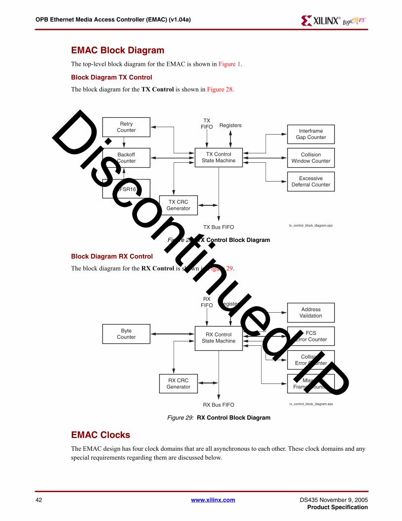
OPB Ethernet Media Access Controller (EMAC) (v104a)
42
D
EMAC Block DiagramThe top-level block diagram for the EMAC is shown in Figure 1
Block Diagram TX Control
The block diagram for the TX Control is shown in Figure 28
Figure 28 TX Control Block Diagram
Figure Top x-ref 28
TXFIFO Registers
TX ControlState Machine
InterframeGap Counter
CollisionWindow Counter
ExcessiveDeferral Counter
tx_control_block_diagrameps
RetryCounter
BackoffCounter
LFSR16
TX CRCGenerator
TX Bus FIFO
Block Diagram RX Control
The block diagram for the RX Control is shown in Figure 29
Figure 29 RX Control Block Diagram
Figure Top x-ref 29
RXFIFO Registers
RX ControlState Machine
AddressVaiidation
FCSError Counter
CollisionError Counter
rx_control_block_diagrameps
MissedFrame Counter
ByteCounter
RX CRCGenerator
RX Bus FIFO
EMAC ClocksThe EMAC design has four clock domains that are all asynchronous to each other These clock domains and any special requirements regarding them are discussed below
iscontinued IP
wwwxilinxcom DS435 November 9 2005Product Specification
OPB Ethernet Media Access Controller (EMAC) (v104a)
DS435 NovProduct Sp
D
Transmit Clock (PHY_tx_clk)
The transmit clock [PHY_tx_clk] is generated by the external PHY and must be used by the EMAC to provide transmit data [PHY_tx_data (30)] and control signals [PHY_tx_en and PHY_tx_er] to the PHY The PHY provides one clock cycle for each nibble of data transferred resulting in a 25 MHz clock for 10BASE-T operation and 25 MHz for 100BASE-T operation at +- 100 ppm with a duty cycle of between 35 and 65 inclusive The PHY derives this clock from an external oscillator or crystal
Receive Clock (PHY_rx_clk)
The receive clock [PHY_rx_clk] is also generated by the external PHY but is derived from the incoming Ethernet traffic Like the transmit clock the PHY provides one clock cycle for each nibble of data transferred resulting in a 25 MHz clock for 10BASE-T operation and 25 MHz for 100BASE-T operation with a duty cycle of between 35 and 65 inclusive while incoming data is valid [PHY_dv is rsquo1rsquo]
The minimum high and low times of the receive clock are at least 35 of the nominal period under all conditions The receive clock is used by the EMAC to sample the receive data [PHY_rx_data(30)] and control signals [PHY_dv and PHY_rx_er] from the PHY
MII Management Clock (PHY_mii_clk)
The Management Data Clock (PHY_mii_clk) is driven by the EMAC to the PHY as the reference for data transfer on the PHY_mii_data signal This signal has no maximum high and low times and need not be periodic but must have a minimum high and low time of at least 160 nS with a corresponding minimum period of 400 nS (corresponds to a maximum of 25 MHz) The MII clock will be a divide by 64 from the OPB bus clock for OPB bus frequencies of 65 to 150 MHz range resulting in a PHY_mii_clk of approximately 1 to 23 MHz
Processor Bus Clock (OPB_Clk)
The majority of the EMAC operation functions in the processor bus clock domain This clock must be greater than to equal to 65 MHz in order to transmit and receive Ethernet data at 100 Mbs and greater than to equal to 65 MHz in order to transmit and receive Ethernet data at 10 Mbs
PHY Interface Signals
PHY_rst_n
Some PHYs use a reset input to establish or re-establish a known initial state The EMAC provides the PHY reset signal (PHY_rst_n) for this purpose This active low output is driven active when OPB_Rst is active when the EMAC Control Register bit 5 is rsquo0rsquo or when a soft reset is performed by writing to the Device Software Reset Register (offset 0x0040) when the software reset function is included in the build (C_RESET_PRESENT = rsquo1rsquo)
PHY_tx_en
The EMAC uses the Transmit Enable signal (PHY_tx_en) to indicate to the PHY that it is providing nibbles at the MII interface for transmission It is asserted synchronously to PHY_tx_clk with the first nibble of the preamble and remains asserted while all nibbles have been transmitted PHY_tx_en is negated prior to the first PHY_tx_clk following the final nibble of a frame
This signal is transferred between the PHY_tx_clk and processor clock domains at the asynchronous TX bus FIFO interface The clock to output delay of this signal must be 0 to 25 nS Figure 30 shows PHY_tx_en timing during a transmission with no collisions
iscontinued IP
ember 9 2005 wwwxilinxcom 43ecification
OPB Ethernet Media Access Controller (EMAC) (v104a)
44
D
PHY_rx_en
The EMAC uses the Receive Enable signal (PHY_rx_en) to indicate to the PHY that the PHY should pass or block receive ethernet data The value of this signal is controlled by the EMAC control register (ECR) bit 4 This signal is not used by many PHY devices
Figure 30 Transmission with no collision
Figure Top x-ref 30
transmission_with_no_collisioneps
PHY_tx_clkPHY_tx_en
PHY_tx_data[30]
PHY_cr5
PHY_col
0ns 50ns 100ns 150ns
0 Preamble SFD D0 D1 CRC 0
PHY_tx_data(30)
The EMAC drives the Transmit Data bus [PHY_tx_data(30)] synchronously to PHY_tx_clk PHY_tx_data(0) is the least significant bit The PHY will transmit the value of PHY_tx_data on every clock cycle that PHY_tx_en is asserted This bus is transferred between the PHY_tx_clk and processor clock domains at the asynchronous TX bus FIFO interface
The clock to output delay of this signal must be 0 to 25 nS The order of the bits nibbles and bytes for transmit and receive are shown in Figure 31
Figure 31 ByteNibble Transmit and Receive Order
Figure Top x-ref 31
Serial Bit StreamFirst bit
D4 D5 D6 D7LSB MST
LSB
MSB
D0
D1
D2
D3
D0 D1 D2 D3
Second nibbleFirst nibble
byte_nibble_transmit_receive_ordereps
PHY_tx_er
The EMAC drives the Transmit coding Error signal (PHY_tx_er) synchronously to PHY_tx_clk When PHY_tx_er is asserted for one or more PHY_tx_clk periods while PHY_tx_en is also asserted and the PHY is operating in 100Mbs mode the PHY transmits one or more symbols that are not part of the valid data or delimiter set somewhere in the frame being transmitted
PHY_tx_er has no effect on PHY operation in 10Mbs mode or when PHY_tx_en is de-asserted This signal is transferred between the PHY_tx_clk and processor clock domains at the asynchronous TX bus FIFO interface
iscontinued IP
wwwxilinxcom DS435 November 9 2005Product Specification
OPB Ethernet Media Access Controller (EMAC) (v104a)
DS435 NovProduct Sp
D
The clock to output delay of this signal must be 0 to 25 nS Table 25 shows the possible combinations for the transmit signals
Table 25 Possible values for PHY_tx_en PHY_tx_er PHY_tx_data[30]
PHY_tx_en PHY_tx_er PHY_tx_data[30] Indication
0 0 0000 through 1111 Normal interframe
0 1 0000 through 1111 Reserved
1 0 0000 through 1111 Normal data transmission
1 1 0000 through 1111 Transmit propagation
PHY_dv
The PHY drives the Receive Data Valid (PHY_dv) signal to indicate that the PHY is driving recovered and decoded nibbles on the PHY_rx_data(30) bus and that the data on PHY_rx_data(30) is synchronous to PHY_rx_clk PHY_dv is driven synchronously to PHY_rx_clk
PHY_dv remains asserted continuously from the first recovered nibble of the frame through the final recovered nibble and is negated prior to the first PHY_rx_clk that follows the final nibble In order for a received frame to be correctly received by the EMAC PHY_dv must encompass the frame starting no later than the Start Frame Delimiter (SFD) and excluding any End-of-Frame delimiter
This signal is transferred between the PHY_rx_clk and processor clock domains at the asynchronous RX bus FIFO interface The PHY will provide a minimum of 10 nS setup and hold time for this signal in reference to PHY_rx_clk Figure 32 shows the behavior of PHY_dv during frame reception
Figure 32 Receive With No Errors
Figure Top x-ref 32
PHY_rx_clk
PHY_dvPHY_rx_er
PHY_rx_data[30] preamble SFD D0 D1 D2 D3 CRC
receive_with_no_errorseps
PHY_rx_data(30)
The PHY drives the Receive Data bus [PHY_rx_data(30)] synchronously to PHY_rx_clk PHY_rx_data(30) contains recovered data for each PHY_rx_clk period in which PHY_dv is asserted PHY_rx_data(0) is the least significant bit The EMAC must not be affected by PHY_rx_data(30) while PHY_dv is de-asserted
Also the EMAC should ignore a special condition that occurs while PHY_dv is de-asserted when the PHY may provide a False Carrier indication by asserting the PHY_rx_er signal while driving the value lt1110gt onto PHY_rx_datalt30gt This bus is transferred between the PHY_rx_clk and processor clock domains at the asynchronous RX bus FIFO interface The PHY will provide a minimum of 10 nS setup and hold time for this signal in reference to RX_CLK
iscontinued IP
ember 9 2005 wwwxilinxcom 45ecification
OPB Ethernet Media Access Controller (EMAC) (v104a)
46
D
PHY_rx_er
The PHY drives the Receive Error signal (PHY_rx_er) synchronously to PHY_rx_clk The PHY drives PHY_rx_er for one or more PHY_rx_clk periods to indicate that an error (eg a coding error or any error that the PHY is capable of detecting) was detected somewhere in the frame presently being transferred from the PHY to the EMAC
PHY_rx_er should have no effect on the EMAC while PHY_dv is de-asserted This signal is transferred between the PHY_rx_clk and processor clock domains at the asynchronous RX bus FIFO interface The PHY will provide a minimum of 10 nS setup and hold time for this signal in reference to PHY_rx_clk Figure 33 shows the behavior of PHY_rx_er during frame reception with errors
Figure 33 Receive With Errors
Figure Top x-ref 33
PHY_rx_clk
PHY_dv
PHY_rx_er
PHY_rx_data[30] SFD D0 D1 xx CRCpreamble D3
receive_with_errorseps
Table 26 shows the possible combinations for the receive signals
Table 26 Possible values for PHY_dv PHY_rx_er and PHY_rx_data[30]
PHY_dv PHY_rx_er PHY_rx_data[30] Indication
0 0 0000 through 1111 Normal interframe
0 1 0000 Normal interframe
0 1 0000 through 1101 Reserved
0 1 1110 False carrier indication
0 1 1111 Reserved
1 0 0000 through 1111 Normal data reception
1 1 0000 through 1111 Data reception with errors
PHY_crs
The PHY drives the Carrier Sense signal (PHY_crs) active to indicate that either the transmit or receive is nonidle when operating in half duplex mode PHY_crs is de-asserted when both the transmit and receive are idle
The PHY drives PHY_crs asserted throughout the duration of a collision condition PHY_crs is not synchronous to either the PHY_tx_clk or the PHY_rx_clk The PHY_crs signal is not used in full duplex mode The PHY_crs signal is used by both the EMAC transmit and receive circuitry and is double synchronized to the processor clock as it enters the EMAC
iscontinued IP
wwwxilinxcom DS435 November 9 2005Product Specification
OPB Ethernet Media Access Controller (EMAC) (v104a)
DS435 NovProduct Sp
D
PHY_col
The PHY drives the Collision detected signal (PHY_col) active to indicate the detection of a collision on the bus The PHY drives PHY_col asserted while the collision condition persists The PHY also drives PHY_col asserted when operating at 10 Mbs for signal_quality_error (SQE) testing
PHY_col is not synchronous to either the PHY_tx_clk or the PHY_rx_clk The PHY_col signal is not used in full duplex mode The PHY_col signal is used by both the EMAC transmit and receive circuitry and is double synchronized to the processor clock as it enters the EMAC Figure 34 shows the behavior of PHY_col during frame transmission with a collision
Figure 34 Transmission With Collision
Figure Top x-ref 34
PHY_tx_clk
PHY_tx_en
PHY_tx_data[30]
PHY_crs
PHY_col
Preamble JAM 00
transmission_with_collisioneps
PHY_mii_data
The Management Data InputOutput signal (PHY_mii_data) is a bidirectional signal between the PHY and the EMAC used to transfer control and status All transfers via the PHY_mii_data are synchronous to the PHY_mii_clk signal PHY_mii_data must be driven through 3-state pins that enable either the EMAC or the PHY to drive the signal
The necessary pull-up and pull-down resistors for this signal are defined in the IEEE Std 8023 paragraph 22442 When the EMAC drives this signal it must provide a minimum of 10nS setup and hold in reference to the PHY_mii_clk signal When the PHY drives this signal it will have a clock to output delay of 0 to 300nS
Management Frame Structure
Data transferred via the PHY_mii_data is structured as frames as shown in Table 27
Table 27 Management Frame Format
Management Frame Fields
PRE ST OP PHYAD REGAD TA DATA IDLE
Read 11 01 10 AAAAA RRRRR Z0 DDDDDDDDDDDDDDDD Z
Write 11 01 01 AAAAA RRRRR 10 DDDDDDDDDDDDDDDD Z
Idle
The IDLE condition on PHY_mii_data is a high-impedance state All 3-state drivers are disabled and the PHYrsquos pull-up resistor will pull the PHY_mii_data line to a logic one
iscontinued IP
ember 9 2005 wwwxilinxcom 47ecification
OPB Ethernet Media Access Controller (EMAC) (v104a)
48
D
Preamble (PRE)
At the beginning of each management transaction the EMAC will transmit 32 contiguous logic one bits on the PHY_mii_data signal
Start of Frame (ST)
The EMAC follows the preamble with the start of frame pattern which is 01
Operation Code (OP)
The operation code is by the EMAC following the start of frame to indicate a read or write transaction A read is designated by 10 and a write by 01
PHY Address (PHYAD)
The next field transmitted by the EMAC is the 5 bit PHY address field This identifies one of up to 32 PHYs connection to the same interface The most significant bit of the address is transmitted first The special PHY address 00000 will address any PHY
Register Address (REGAD)
The EMAC follows the PHY address field with the transmission of the 5 bit register address field allowing the access of up to 32 PHY registers The most significant bit of the address is transmitted first
Turn Around (TA)
A turn around period of 2 bit times follows the register field and precedes the data field to prevent contention during a read cycle For a read both the EMAC and the PHY remain in a high-impedance state for the first bit time of the turnaround The PHY will drive a zero bit during the second bit time of the turnaround of a read transaction
During a write the EMAC must drive a one bit for the first bit time of the turnaround and a zero bit for the second bit time of the turnaround Figure 35 shows the behavior of the PHY_mii_data signal during the turnaround field of a read transaction
Figure 35 MDIO Read Turn Around
Figure Top x-ref 35
mdio_read_turnaroundeps
MDC
MDIO
0ZR
Data
The data field is 16 bits and is transmitted and received with bit 15 (MSb) first of the register being addressed
Packet FIFO InterfaceThe EMAC uses the special Mark Release and Restore features of the packet FIFOs to assist in management of transmit and receive data under special circumstances
The use of these features are discussed here as it applies to Ethernet operation Also discussed are special considerations required to support a multi-cycle dead FIFO access time following a Mark Release and Restore operation
iscontinued IP
wwwxilinxcom DS435 November 9 2005Product Specification
OPB Ethernet Media Access Controller (EMAC) (v104a)
DS435 NovProduct Sp
D
Transmit Packet FIFO Interface
The use of the special FIFO features greatly simplifies the retransmission of a packet following a collision on a half duplex bus (the features are not needed for full duplex operation) When the EMAC is ready to transmit (transmit enable is rsquo1rsquo and the transmit length register is not empty) and it is in half-duplex mode and it is not deferring it will perform a Mark in the transmit FIFO and begin reading transmit data (after a several cycle delay required by the FIFO) while counting down the length value
If no collision occurs after 64 byte times the EMAC will perform a Release to allow the FIFO locations containing the first parts of the transmit to be reused Since the EMAC will not be able to read during the several cycles following the release it will have to insure that the transmit bus FIFO contains enough nibbles to sustain continuous transmission flow until packet FIFO reads can be resumed
If a collision does occur in the first 64 byte times the EMAC will transmit the JAM pattern increment the retry count and if retries are less than 16 perform backoff and a Restore on the packet FIFO Since the EMAC will be performing backoff and deferral it will not need to access the FIFO during the Dead FIFO access time following the Restore
If a transmission was attempted 16 retries and was unsuccessful the EMAC will perform a Release and flush the remainder of the failed packet data from the transmit packet FIFO by performing the number of reads required to decrement the length counter to zero
Receive Packet FIFO Interface
The use of the special FIFO features greatly simplifies the flushing of a packet following a receive error When the EMAC detects that a packet is being received the EMAC will perform a Mark on the receive packet FIFO and begin storing receive data (after a several cycle delay required by the FIFO) while counting up the length value
The EMAC will continue reception and will store data into the receive FIFO until either the reception is successful a receive error occurs or the receive packet FIFO becomes full and overruns
Following the completion of a successful receive the EMAC will perform a Release However if an error occurs during reception or if the receive packet FIFO becomes full and overruns the EMAC will discontinue data storage into the receive packet FIFO and will flush all packet data stored there associated with the bad packet by performing a Restore There should be not be a need for special handling of the dead FIFO access time for Restore operations
When RX checksum offloading is included in the design then the Release signal will also mark the end of packet and cause the RAW checksum and RX status to be written into the FIFO This will eventually be read out of the FIFO by the DMA and put in the SR field of the RX buffer descriptor
Receive Address ValidationDestination addresses are classified as either unicast (a single station address indicated by the IG bit =rsquo0rsquo) multicast (a group of stations indicated by the IG bit =rsquo1rsquo) and the multicast subgroup broadcast (all stations on the network)
The EMAC provides flexibility for enabling each of these modes as well as a promiscuous address mode where it accepts all addresses The flow chart in Figure 36 shows the address validation process
iscontinued IP
ember 9 2005 wwwxilinxcom 49ecification
OPB Ethernet Media Access Controller (EMAC) (v104a)
50
D
Figure 36 Address Validation Process
Figure Top x-ref 36
BroadcastAddress
Multicast allEnabled
CAM Existsamp Enabled
BroadcastEnabled
UnicastEnabled
AddressValid
PauseEnabled
PromiscuousEnabled
PauseMulticast
Addr
=SAH amp SAL
=1 0f 64 CAM
Entries
MulticastAddress
TT
T T T
(16)1(17)1(15)1(20)1 (14)1 (21)1
OR
TT
T T T
T
Check Address
Notes
1 The number in parenthesis indicates bit in ECR
receive_addr_validationeps
Using the CAM for Receive Address Validation
In order to use the CAM for receive address validation it must be included in the design by setting the C_CAM_EXIST parameter = rsquo1rsquo The parameter C_CAM_BRAM_0_SRL_1 is set to select between BRAM or SRL logic based implementation This is strictly a trade off between using BRAMS or FPGA logic
The CAM is capable of holding up to 64 48 bit MAC addresses The CAM can not be read or reset To clear the CAM each of the 64 entries must be written
To write an entry to the CAM place the upper 16 bits of the MAC address in bits 16 through 31 of the CAMH register along with the CAM entry address in bits 10 through 15 The address should be in the range 0 to 63 inclusive The lower 32 bits of the MAC address must be placed in the CAML register
The write to the CAM is initiated by writing a rsquo1rsquo to bit 23 of the ECR This bit will automatically reset to rsquo0rsquo
Once all of the entries have been placed in the CAM the CAM must be enabled by writing a rsquo1rsquo to bit 20 of the ECR
iscontinued IP
wwwxilinxcom DS435 November 9 2005Product Specification
OPB Ethernet Media Access Controller (EMAC) (v104a)
DS435 NovProduct Sp
D
Error Handling
Transmit Errors
Transmit errors detected by the EMAC circuitry are noted in the transmit status word and with interrupts and an error counter for maximum software implementation flexibility
Receive Errors
The IEEE Std 8023 prevents packets with error conditions from being passed to the software interface The EMAC circuitry does provide interrupts status register bits and error counters to allow the software to monitor receive error conditions When a received frame is detected to have an error the data is discarded by using the packet FIFO mark and restore features No receive status word or length is stored for that frame
MII Management Errors
The MII Management interface will detect and indicate that a read from a PHY register is invalid and the operation should be retried when the PHY does not drive the PHY_mii_data signal to the low state during a read turn-around cycle This error condition is flagged in the MII management control register
Design ConstraintsThe Ethernet Core requires design constraints to guarantee performance These constraints should be placed in a UCF file for the top level of the design The following example of the constraint text is based on the port names of the Ethernet core If these ports are mapped to FPGA pin names that are different the FPGA pin names should be substituted for the port names in the example below
NET phy_rx_clk TNM_NET = RXCLK_GRP
NET phy_tx_clk TNM_NET = TXCLK_GRP
TIMESPEC TSTXOUT = FROM TXCLK_GRP TO PADS 10 ns
TIMESPEC TSRXIN = FROM PADS TO RXCLK_GRP 6 ns
NET opb_rst TIG
NET phy_rx_clk USELOWSKEWLINES1
NET phy_tx_clk USELOWSKEWLINES1
NET phy_tx_clk MAXSKEW= 20 ns2
NET phy_rx_clk MAXSKEW= 20 ns2
NET phy_tx_clk MAXSKEW= 10 ns3
NET phy_rx_clk MAXSKEW= 10 ns3
NET phy_rx_clk PERIOD = 40 ns HIGH 14 ns
NET phy_tx_clk PERIOD = 40 ns HIGH 14 ns
NET phy_rx_datalt3gt NODELAY2
1 Should be used only for Virtex Virtex-E Spartan-II or Spartan-IIE devices2 Should be used for all devices except Virtex-43 Should be used only for Virtex-4
iscontinued IP
ember 9 2005 wwwxilinxcom 51ecification
OPB Ethernet Media Access Controller (EMAC) (v104a)
52
C_I
PIF
_WR
FIF
O_D
EP
TH
1638
D
NET phy_rx_datalt2gt NODELAY2
NET phy_rx_datalt1gt NODELAY2
NET phy_rx_datalt0gt NODELAY2
NET phy_dv NODELAY2
NET phy_rx_er NODELAY2
NET phy_crs NODELAY2
NET phy_col NODELAY2
NET phy_rx_datalt3gt IOBDELAY=NONE3
NET phy_rx_datalt2gt IOBDELAY=NONE3
NET phy_rx_datalt1gt IOBDELAY=NONE3
NET phy_rx_datalt0gt IOBDELAY=NONE3
NET phy_dv IOBDELAY=NONE3
NET phy_rx_er IOBDELAY=NONE3
NET phy_crs IOBDELAY=NONE3
NET phy_col IOBDELAY=NONE3
Design Implementation
Device Utilization and Performance Benchmarks
Since the EMAC is a module that will be used with other design pieces in the FPGA the utilization and timing numbers reported in this section are just estimates As the EMAC is combined with other pieces of the FPGA design the utilization of FPGA resources and timing of the EMAC design will vary from the results reported here
In order to analyze the EMACrsquos timing within the FPGA a design will be created that instantiates the EMAC with the following parameters set
The EMAC benchmarks are shown in Table 28 for a Virtex-II Pro -7
Table 28 EMAC FPGA Performance and Resource Utilization Benchmarks (Virtex-II Pro -7)
Parameter Values Device Resources
C_I
PIF
_RD
FIF
O_D
EP
TH
C_D
EV
_MIR
_EN
AB
LE
C_D
MA
_PR
ES
EN
T
C_R
ES
ET
_PR
ES
EN
T
C_I
NC
LUD
E_D
EV
_PE
NC
OD
ER
C_C
AM
_BR
AM
_0_S
RL_
1
C_C
AM
_EX
IST
C_J
UM
BO
_EX
IST
C_M
AC
_FIF
O_B
RA
M_1
_SR
L_0
C_M
AC
_FIF
O_D
EP
TH
C_H
ALF
_DU
PLE
X_E
XIS
T
C_T
XR
X_D
RE
_TY
PE
C_T
XR
X_I
NC
LUD
E_C
SU
M
SlicesSlice Flip- Flops
BRAMS4-
input LUTs
fMAX
(MHz)
4 16384 0 1 0 0 0 0 0 1 16 0 0 1474 1538 5 1960 143
iscontinued IP
wwwxilinxcom DS435 November 9 2005Product Specification
OPB Ethernet Media Access Controller (EMAC) (v104a)
DS435 NovProduct Sp
1638
1638
1638
1638
1638
1638
1638
1638
1638
1638
1638
1638
3276
6553
1310
2621
2621
2621
2621
2621
2621
2621
2621
2621
3276
Notes1 I1
peres
2 Ple
D
Specification Exceptions The EMAC design currently has no exceptions to the mandatory IEEE Std 8023 MII interface requirements
Reference DocumentsThe following document contains reference information important to understanding the EMAC design
bull IEEE Std 8023
bull OPB_IPIF_V2_00_l
4 16384 0 1 0 0 0 0 0 0 16 0 0 1499 1556 2 1992 143
4 16384 0 1 0 0 0 0 0 1 16 1 0 0 1615 1706 5 2165 143
4 16384 0 1 0 1 0 0 0 1 16 1 0 0 1620 1705 5 2173 143
4 16384 0 1 1 1 0 0 0 1 16 1 0 0 1640 1715 5 2192 143
4 16384 1 1 1 1 0 0 0 1 16 1 0 0 1653 1719 5 2211 143
4 16384 1 1 1 1 0 0 0 1 32 1 0 0 1670 1722 5 2247 143
4 16384 1 1 1 1 0 0 0 0 32 1 0 0 1697 1740 2 2280 143
4 16384 1 1 1 1 0 0 0 0 64 1 0 0 1728 1743 2 2343 143
4 16384 1 1 1 1 0 0 0 1 64 1 0 0 1702 1725 5 2310 143
4 16384 1 1 1 1 0 0 1 1 64 1 0 0 1722 1741 5 2346 143
4 16384 1 1 1 1 0 1 1 1 64 1 0 0 2143 1997 17 2961 142
4 16384 1 1 1 1 1 1 1 1 64 1 0 0 2382 1934 5 3418 129
8 16384 1 1 1 1 0 1 1 1 64 1 0 0 2382 2004 18 2980 143
6 16384 1 1 1 1 0 1 1 1 64 1 0 0 2152 2012 20 1981 136
72 16384 1 1 1 1 0 1 1 1 64 1 0 0 2158 2017 24 2988 113
44 16384 1 1 1 1 0 1 1 1 64 1 0 0 2165 2023 32 3006 143
44 262144 1 1 1 1 0 1 1 1 64 1 0 0 2186 2047 47 3033 143
44 262144 1 2 1 1 0 1 1 1 64 1 0 0 3073 2706 47 4469 115
44 262144 1 3 1 1 0 1 1 1 64 1 0 0 3459 2873 47 5129 123
44 262144 1 3 1 1 1 1 1 0 64 1 0 0 3739 2832 32 5631 122
44 262144 1 3 1 1 0 1 1 1 64 1 1 0 3576 3016 47 5337 114
44 262144 1 3 1 1 1 1 1 0 64 1 1 0 3857 2977 32 5839 116
44 262144 1 3 1 1 0 1 1 1 64 1 0 1 3781 3237 47 5655 119
44 262144 1 3 1 1 1 1 1 0 64 1 0 1 4021 3198 32 6157 126
8 32768 1 3 1 1 1 0 1 1 64 1 1 0 3125 2725 7 4640 135
94 with overall effort level of high and synthesis resource sharing on into a xc2vp20-7-ff1152 device with opb_clk riod constrained to 7 nS (1428 Mhz) Turning resource sharing off in XST may increase fMAX but also may increase ources used Using -Timing based Map may also increase fMAXase refer to Table 1 for a definition of these parameters
Table 28 EMAC FPGA Performance and Resource Utilization Benchmarks (Virtex-II Pro -7) (Contd)
iscontinued IP
ember 9 2005 wwwxilinxcom 53ecification
OPB Ethernet Media Access Controller (EMAC) (v104a)
54
D
bull DMA_SG_V1_04_b
Revision History
Date Version Revision
12604 11 Initial Xilinx release
21605 12Converted to new DS template updated figures to Xilinx graphic standards reformatted tables incorporated CR198497
iscontinued IP
wwwxilinxcom DS435 November 9 2005Product Specification
- OPB Ethernet Media Access Controller (EMAC) (v104a)
-
- Introduction
- Features
- Evaluation Version
- Functional Description
- EMAC Endianess
- Ethernet Protocol
- EMAC Design Parameters
- Allowable Parameter Combinations
- Detailed Parameter Descriptions
- EMAC IO Signals
- EMAC Port Dependencies
- EMAC Interrupt Interface
- Detailed Interrupt Descriptions
- EMAC Register Definition
- EMAC IPIF Registers
- EMAC Core Registers
- EMAC Module Identification Register (EMIR offset 0x1100)
- EMAC Control Register (ECR offset 0x1104)
- Interframe Gap Register (IFGP offset 0x1108)
- Receive Packet Length Register (RPLR offset 0x111C)
- Transmit Packet Length Register (TPLR offset 0x1120)
- Receive Status Register (RSR offset 0x113C)
- Transmit Status Register (TSR offset 0x1124)
- Station Address High Register (SAH offset 0x110C)
- Station Address Low Register (SAL offset 0x1110)
- MII Management Control Register (MGTCR offset 0x1114)
- MII Management Data Register (MGTDR offset 0x1118)
- Receive Missed Frame Count (RMFC offset 0x1128)
- Receive Collision Count (RCC offset 0x112C)
- Receive FCS Error Count (RFCSEC offset 0x1130)
- Receive Alignment Error Count (RAEC offset 0x1134)
- Transmit Excess Deferral Count (TEDC offset 0x1138)
- Receive CAM Entry High Register (CAMH offset 0x1140)
- Receive CAM Entry Low Register (SAL offset 0x1144)
- EMAC Block Diagram
- EMAC Clocks
- Transmit Clock (PHY_tx_clk)
- Receive Clock (PHY_rx_clk)
- MII Management Clock (PHY_mii_clk)
- Processor Bus Clock (OPB_Clk)
- PHY Interface Signals
- PHY_rst_n
- PHY_tx_en
- PHY_rx_en
- PHY_tx_data(30)
- PHY_tx_er
- PHY_dv
- PHY_rx_data(30)
- PHY_rx_er
- PHY_crs
- PHY_col
- PHY_mii_data
- Packet FIFO Interface
- Transmit Packet FIFO Interface
- Receive Packet FIFO Interface
- Receive Address Validation
- Using the CAM for Receive Address Validation
- Error Handling
- Transmit Errors
- Receive Errors
- MII Management Errors
- Design Constraints
- Design Implementation
- Device Utilization and Performance Benchmarks
- Specification Exceptions
- Reference Documents
- Revision History
-
OPB Ethernet Media Access Controller (EMAC) (v104a)
DS435 NovProduct Sp
D
Transmit Clock (PHY_tx_clk)
The transmit clock [PHY_tx_clk] is generated by the external PHY and must be used by the EMAC to provide transmit data [PHY_tx_data (30)] and control signals [PHY_tx_en and PHY_tx_er] to the PHY The PHY provides one clock cycle for each nibble of data transferred resulting in a 25 MHz clock for 10BASE-T operation and 25 MHz for 100BASE-T operation at +- 100 ppm with a duty cycle of between 35 and 65 inclusive The PHY derives this clock from an external oscillator or crystal
Receive Clock (PHY_rx_clk)
The receive clock [PHY_rx_clk] is also generated by the external PHY but is derived from the incoming Ethernet traffic Like the transmit clock the PHY provides one clock cycle for each nibble of data transferred resulting in a 25 MHz clock for 10BASE-T operation and 25 MHz for 100BASE-T operation with a duty cycle of between 35 and 65 inclusive while incoming data is valid [PHY_dv is rsquo1rsquo]
The minimum high and low times of the receive clock are at least 35 of the nominal period under all conditions The receive clock is used by the EMAC to sample the receive data [PHY_rx_data(30)] and control signals [PHY_dv and PHY_rx_er] from the PHY
MII Management Clock (PHY_mii_clk)
The Management Data Clock (PHY_mii_clk) is driven by the EMAC to the PHY as the reference for data transfer on the PHY_mii_data signal This signal has no maximum high and low times and need not be periodic but must have a minimum high and low time of at least 160 nS with a corresponding minimum period of 400 nS (corresponds to a maximum of 25 MHz) The MII clock will be a divide by 64 from the OPB bus clock for OPB bus frequencies of 65 to 150 MHz range resulting in a PHY_mii_clk of approximately 1 to 23 MHz
Processor Bus Clock (OPB_Clk)
The majority of the EMAC operation functions in the processor bus clock domain This clock must be greater than to equal to 65 MHz in order to transmit and receive Ethernet data at 100 Mbs and greater than to equal to 65 MHz in order to transmit and receive Ethernet data at 10 Mbs
PHY Interface Signals
PHY_rst_n
Some PHYs use a reset input to establish or re-establish a known initial state The EMAC provides the PHY reset signal (PHY_rst_n) for this purpose This active low output is driven active when OPB_Rst is active when the EMAC Control Register bit 5 is rsquo0rsquo or when a soft reset is performed by writing to the Device Software Reset Register (offset 0x0040) when the software reset function is included in the build (C_RESET_PRESENT = rsquo1rsquo)
PHY_tx_en
The EMAC uses the Transmit Enable signal (PHY_tx_en) to indicate to the PHY that it is providing nibbles at the MII interface for transmission It is asserted synchronously to PHY_tx_clk with the first nibble of the preamble and remains asserted while all nibbles have been transmitted PHY_tx_en is negated prior to the first PHY_tx_clk following the final nibble of a frame
This signal is transferred between the PHY_tx_clk and processor clock domains at the asynchronous TX bus FIFO interface The clock to output delay of this signal must be 0 to 25 nS Figure 30 shows PHY_tx_en timing during a transmission with no collisions
iscontinued IP
ember 9 2005 wwwxilinxcom 43ecification
OPB Ethernet Media Access Controller (EMAC) (v104a)
44
D
PHY_rx_en
The EMAC uses the Receive Enable signal (PHY_rx_en) to indicate to the PHY that the PHY should pass or block receive ethernet data The value of this signal is controlled by the EMAC control register (ECR) bit 4 This signal is not used by many PHY devices
Figure 30 Transmission with no collision
Figure Top x-ref 30
transmission_with_no_collisioneps
PHY_tx_clkPHY_tx_en
PHY_tx_data[30]
PHY_cr5
PHY_col
0ns 50ns 100ns 150ns
0 Preamble SFD D0 D1 CRC 0
PHY_tx_data(30)
The EMAC drives the Transmit Data bus [PHY_tx_data(30)] synchronously to PHY_tx_clk PHY_tx_data(0) is the least significant bit The PHY will transmit the value of PHY_tx_data on every clock cycle that PHY_tx_en is asserted This bus is transferred between the PHY_tx_clk and processor clock domains at the asynchronous TX bus FIFO interface
The clock to output delay of this signal must be 0 to 25 nS The order of the bits nibbles and bytes for transmit and receive are shown in Figure 31
Figure 31 ByteNibble Transmit and Receive Order
Figure Top x-ref 31
Serial Bit StreamFirst bit
D4 D5 D6 D7LSB MST
LSB
MSB
D0
D1
D2
D3
D0 D1 D2 D3
Second nibbleFirst nibble
byte_nibble_transmit_receive_ordereps
PHY_tx_er
The EMAC drives the Transmit coding Error signal (PHY_tx_er) synchronously to PHY_tx_clk When PHY_tx_er is asserted for one or more PHY_tx_clk periods while PHY_tx_en is also asserted and the PHY is operating in 100Mbs mode the PHY transmits one or more symbols that are not part of the valid data or delimiter set somewhere in the frame being transmitted
PHY_tx_er has no effect on PHY operation in 10Mbs mode or when PHY_tx_en is de-asserted This signal is transferred between the PHY_tx_clk and processor clock domains at the asynchronous TX bus FIFO interface
iscontinued IP
wwwxilinxcom DS435 November 9 2005Product Specification
OPB Ethernet Media Access Controller (EMAC) (v104a)
DS435 NovProduct Sp
D
The clock to output delay of this signal must be 0 to 25 nS Table 25 shows the possible combinations for the transmit signals
Table 25 Possible values for PHY_tx_en PHY_tx_er PHY_tx_data[30]
PHY_tx_en PHY_tx_er PHY_tx_data[30] Indication
0 0 0000 through 1111 Normal interframe
0 1 0000 through 1111 Reserved
1 0 0000 through 1111 Normal data transmission
1 1 0000 through 1111 Transmit propagation
PHY_dv
The PHY drives the Receive Data Valid (PHY_dv) signal to indicate that the PHY is driving recovered and decoded nibbles on the PHY_rx_data(30) bus and that the data on PHY_rx_data(30) is synchronous to PHY_rx_clk PHY_dv is driven synchronously to PHY_rx_clk
PHY_dv remains asserted continuously from the first recovered nibble of the frame through the final recovered nibble and is negated prior to the first PHY_rx_clk that follows the final nibble In order for a received frame to be correctly received by the EMAC PHY_dv must encompass the frame starting no later than the Start Frame Delimiter (SFD) and excluding any End-of-Frame delimiter
This signal is transferred between the PHY_rx_clk and processor clock domains at the asynchronous RX bus FIFO interface The PHY will provide a minimum of 10 nS setup and hold time for this signal in reference to PHY_rx_clk Figure 32 shows the behavior of PHY_dv during frame reception
Figure 32 Receive With No Errors
Figure Top x-ref 32
PHY_rx_clk
PHY_dvPHY_rx_er
PHY_rx_data[30] preamble SFD D0 D1 D2 D3 CRC
receive_with_no_errorseps
PHY_rx_data(30)
The PHY drives the Receive Data bus [PHY_rx_data(30)] synchronously to PHY_rx_clk PHY_rx_data(30) contains recovered data for each PHY_rx_clk period in which PHY_dv is asserted PHY_rx_data(0) is the least significant bit The EMAC must not be affected by PHY_rx_data(30) while PHY_dv is de-asserted
Also the EMAC should ignore a special condition that occurs while PHY_dv is de-asserted when the PHY may provide a False Carrier indication by asserting the PHY_rx_er signal while driving the value lt1110gt onto PHY_rx_datalt30gt This bus is transferred between the PHY_rx_clk and processor clock domains at the asynchronous RX bus FIFO interface The PHY will provide a minimum of 10 nS setup and hold time for this signal in reference to RX_CLK
iscontinued IP
ember 9 2005 wwwxilinxcom 45ecification
OPB Ethernet Media Access Controller (EMAC) (v104a)
46
D
PHY_rx_er
The PHY drives the Receive Error signal (PHY_rx_er) synchronously to PHY_rx_clk The PHY drives PHY_rx_er for one or more PHY_rx_clk periods to indicate that an error (eg a coding error or any error that the PHY is capable of detecting) was detected somewhere in the frame presently being transferred from the PHY to the EMAC
PHY_rx_er should have no effect on the EMAC while PHY_dv is de-asserted This signal is transferred between the PHY_rx_clk and processor clock domains at the asynchronous RX bus FIFO interface The PHY will provide a minimum of 10 nS setup and hold time for this signal in reference to PHY_rx_clk Figure 33 shows the behavior of PHY_rx_er during frame reception with errors
Figure 33 Receive With Errors
Figure Top x-ref 33
PHY_rx_clk
PHY_dv
PHY_rx_er
PHY_rx_data[30] SFD D0 D1 xx CRCpreamble D3
receive_with_errorseps
Table 26 shows the possible combinations for the receive signals
Table 26 Possible values for PHY_dv PHY_rx_er and PHY_rx_data[30]
PHY_dv PHY_rx_er PHY_rx_data[30] Indication
0 0 0000 through 1111 Normal interframe
0 1 0000 Normal interframe
0 1 0000 through 1101 Reserved
0 1 1110 False carrier indication
0 1 1111 Reserved
1 0 0000 through 1111 Normal data reception
1 1 0000 through 1111 Data reception with errors
PHY_crs
The PHY drives the Carrier Sense signal (PHY_crs) active to indicate that either the transmit or receive is nonidle when operating in half duplex mode PHY_crs is de-asserted when both the transmit and receive are idle
The PHY drives PHY_crs asserted throughout the duration of a collision condition PHY_crs is not synchronous to either the PHY_tx_clk or the PHY_rx_clk The PHY_crs signal is not used in full duplex mode The PHY_crs signal is used by both the EMAC transmit and receive circuitry and is double synchronized to the processor clock as it enters the EMAC
iscontinued IP
wwwxilinxcom DS435 November 9 2005Product Specification
OPB Ethernet Media Access Controller (EMAC) (v104a)
DS435 NovProduct Sp
D
PHY_col
The PHY drives the Collision detected signal (PHY_col) active to indicate the detection of a collision on the bus The PHY drives PHY_col asserted while the collision condition persists The PHY also drives PHY_col asserted when operating at 10 Mbs for signal_quality_error (SQE) testing
PHY_col is not synchronous to either the PHY_tx_clk or the PHY_rx_clk The PHY_col signal is not used in full duplex mode The PHY_col signal is used by both the EMAC transmit and receive circuitry and is double synchronized to the processor clock as it enters the EMAC Figure 34 shows the behavior of PHY_col during frame transmission with a collision
Figure 34 Transmission With Collision
Figure Top x-ref 34
PHY_tx_clk
PHY_tx_en
PHY_tx_data[30]
PHY_crs
PHY_col
Preamble JAM 00
transmission_with_collisioneps
PHY_mii_data
The Management Data InputOutput signal (PHY_mii_data) is a bidirectional signal between the PHY and the EMAC used to transfer control and status All transfers via the PHY_mii_data are synchronous to the PHY_mii_clk signal PHY_mii_data must be driven through 3-state pins that enable either the EMAC or the PHY to drive the signal
The necessary pull-up and pull-down resistors for this signal are defined in the IEEE Std 8023 paragraph 22442 When the EMAC drives this signal it must provide a minimum of 10nS setup and hold in reference to the PHY_mii_clk signal When the PHY drives this signal it will have a clock to output delay of 0 to 300nS
Management Frame Structure
Data transferred via the PHY_mii_data is structured as frames as shown in Table 27
Table 27 Management Frame Format
Management Frame Fields
PRE ST OP PHYAD REGAD TA DATA IDLE
Read 11 01 10 AAAAA RRRRR Z0 DDDDDDDDDDDDDDDD Z
Write 11 01 01 AAAAA RRRRR 10 DDDDDDDDDDDDDDDD Z
Idle
The IDLE condition on PHY_mii_data is a high-impedance state All 3-state drivers are disabled and the PHYrsquos pull-up resistor will pull the PHY_mii_data line to a logic one
iscontinued IP
ember 9 2005 wwwxilinxcom 47ecification
OPB Ethernet Media Access Controller (EMAC) (v104a)
48
D
Preamble (PRE)
At the beginning of each management transaction the EMAC will transmit 32 contiguous logic one bits on the PHY_mii_data signal
Start of Frame (ST)
The EMAC follows the preamble with the start of frame pattern which is 01
Operation Code (OP)
The operation code is by the EMAC following the start of frame to indicate a read or write transaction A read is designated by 10 and a write by 01
PHY Address (PHYAD)
The next field transmitted by the EMAC is the 5 bit PHY address field This identifies one of up to 32 PHYs connection to the same interface The most significant bit of the address is transmitted first The special PHY address 00000 will address any PHY
Register Address (REGAD)
The EMAC follows the PHY address field with the transmission of the 5 bit register address field allowing the access of up to 32 PHY registers The most significant bit of the address is transmitted first
Turn Around (TA)
A turn around period of 2 bit times follows the register field and precedes the data field to prevent contention during a read cycle For a read both the EMAC and the PHY remain in a high-impedance state for the first bit time of the turnaround The PHY will drive a zero bit during the second bit time of the turnaround of a read transaction
During a write the EMAC must drive a one bit for the first bit time of the turnaround and a zero bit for the second bit time of the turnaround Figure 35 shows the behavior of the PHY_mii_data signal during the turnaround field of a read transaction
Figure 35 MDIO Read Turn Around
Figure Top x-ref 35
mdio_read_turnaroundeps
MDC
MDIO
0ZR
Data
The data field is 16 bits and is transmitted and received with bit 15 (MSb) first of the register being addressed
Packet FIFO InterfaceThe EMAC uses the special Mark Release and Restore features of the packet FIFOs to assist in management of transmit and receive data under special circumstances
The use of these features are discussed here as it applies to Ethernet operation Also discussed are special considerations required to support a multi-cycle dead FIFO access time following a Mark Release and Restore operation
iscontinued IP
wwwxilinxcom DS435 November 9 2005Product Specification
OPB Ethernet Media Access Controller (EMAC) (v104a)
DS435 NovProduct Sp
D
Transmit Packet FIFO Interface
The use of the special FIFO features greatly simplifies the retransmission of a packet following a collision on a half duplex bus (the features are not needed for full duplex operation) When the EMAC is ready to transmit (transmit enable is rsquo1rsquo and the transmit length register is not empty) and it is in half-duplex mode and it is not deferring it will perform a Mark in the transmit FIFO and begin reading transmit data (after a several cycle delay required by the FIFO) while counting down the length value
If no collision occurs after 64 byte times the EMAC will perform a Release to allow the FIFO locations containing the first parts of the transmit to be reused Since the EMAC will not be able to read during the several cycles following the release it will have to insure that the transmit bus FIFO contains enough nibbles to sustain continuous transmission flow until packet FIFO reads can be resumed
If a collision does occur in the first 64 byte times the EMAC will transmit the JAM pattern increment the retry count and if retries are less than 16 perform backoff and a Restore on the packet FIFO Since the EMAC will be performing backoff and deferral it will not need to access the FIFO during the Dead FIFO access time following the Restore
If a transmission was attempted 16 retries and was unsuccessful the EMAC will perform a Release and flush the remainder of the failed packet data from the transmit packet FIFO by performing the number of reads required to decrement the length counter to zero
Receive Packet FIFO Interface
The use of the special FIFO features greatly simplifies the flushing of a packet following a receive error When the EMAC detects that a packet is being received the EMAC will perform a Mark on the receive packet FIFO and begin storing receive data (after a several cycle delay required by the FIFO) while counting up the length value
The EMAC will continue reception and will store data into the receive FIFO until either the reception is successful a receive error occurs or the receive packet FIFO becomes full and overruns
Following the completion of a successful receive the EMAC will perform a Release However if an error occurs during reception or if the receive packet FIFO becomes full and overruns the EMAC will discontinue data storage into the receive packet FIFO and will flush all packet data stored there associated with the bad packet by performing a Restore There should be not be a need for special handling of the dead FIFO access time for Restore operations
When RX checksum offloading is included in the design then the Release signal will also mark the end of packet and cause the RAW checksum and RX status to be written into the FIFO This will eventually be read out of the FIFO by the DMA and put in the SR field of the RX buffer descriptor
Receive Address ValidationDestination addresses are classified as either unicast (a single station address indicated by the IG bit =rsquo0rsquo) multicast (a group of stations indicated by the IG bit =rsquo1rsquo) and the multicast subgroup broadcast (all stations on the network)
The EMAC provides flexibility for enabling each of these modes as well as a promiscuous address mode where it accepts all addresses The flow chart in Figure 36 shows the address validation process
iscontinued IP
ember 9 2005 wwwxilinxcom 49ecification
OPB Ethernet Media Access Controller (EMAC) (v104a)
50
D
Figure 36 Address Validation Process
Figure Top x-ref 36
BroadcastAddress
Multicast allEnabled
CAM Existsamp Enabled
BroadcastEnabled
UnicastEnabled
AddressValid
PauseEnabled
PromiscuousEnabled
PauseMulticast
Addr
=SAH amp SAL
=1 0f 64 CAM
Entries
MulticastAddress
TT
T T T
(16)1(17)1(15)1(20)1 (14)1 (21)1
OR
TT
T T T
T
Check Address
Notes
1 The number in parenthesis indicates bit in ECR
receive_addr_validationeps
Using the CAM for Receive Address Validation
In order to use the CAM for receive address validation it must be included in the design by setting the C_CAM_EXIST parameter = rsquo1rsquo The parameter C_CAM_BRAM_0_SRL_1 is set to select between BRAM or SRL logic based implementation This is strictly a trade off between using BRAMS or FPGA logic
The CAM is capable of holding up to 64 48 bit MAC addresses The CAM can not be read or reset To clear the CAM each of the 64 entries must be written
To write an entry to the CAM place the upper 16 bits of the MAC address in bits 16 through 31 of the CAMH register along with the CAM entry address in bits 10 through 15 The address should be in the range 0 to 63 inclusive The lower 32 bits of the MAC address must be placed in the CAML register
The write to the CAM is initiated by writing a rsquo1rsquo to bit 23 of the ECR This bit will automatically reset to rsquo0rsquo
Once all of the entries have been placed in the CAM the CAM must be enabled by writing a rsquo1rsquo to bit 20 of the ECR
iscontinued IP
wwwxilinxcom DS435 November 9 2005Product Specification
OPB Ethernet Media Access Controller (EMAC) (v104a)
DS435 NovProduct Sp
D
Error Handling
Transmit Errors
Transmit errors detected by the EMAC circuitry are noted in the transmit status word and with interrupts and an error counter for maximum software implementation flexibility
Receive Errors
The IEEE Std 8023 prevents packets with error conditions from being passed to the software interface The EMAC circuitry does provide interrupts status register bits and error counters to allow the software to monitor receive error conditions When a received frame is detected to have an error the data is discarded by using the packet FIFO mark and restore features No receive status word or length is stored for that frame
MII Management Errors
The MII Management interface will detect and indicate that a read from a PHY register is invalid and the operation should be retried when the PHY does not drive the PHY_mii_data signal to the low state during a read turn-around cycle This error condition is flagged in the MII management control register
Design ConstraintsThe Ethernet Core requires design constraints to guarantee performance These constraints should be placed in a UCF file for the top level of the design The following example of the constraint text is based on the port names of the Ethernet core If these ports are mapped to FPGA pin names that are different the FPGA pin names should be substituted for the port names in the example below
NET phy_rx_clk TNM_NET = RXCLK_GRP
NET phy_tx_clk TNM_NET = TXCLK_GRP
TIMESPEC TSTXOUT = FROM TXCLK_GRP TO PADS 10 ns
TIMESPEC TSRXIN = FROM PADS TO RXCLK_GRP 6 ns
NET opb_rst TIG
NET phy_rx_clk USELOWSKEWLINES1
NET phy_tx_clk USELOWSKEWLINES1
NET phy_tx_clk MAXSKEW= 20 ns2
NET phy_rx_clk MAXSKEW= 20 ns2
NET phy_tx_clk MAXSKEW= 10 ns3
NET phy_rx_clk MAXSKEW= 10 ns3
NET phy_rx_clk PERIOD = 40 ns HIGH 14 ns
NET phy_tx_clk PERIOD = 40 ns HIGH 14 ns
NET phy_rx_datalt3gt NODELAY2
1 Should be used only for Virtex Virtex-E Spartan-II or Spartan-IIE devices2 Should be used for all devices except Virtex-43 Should be used only for Virtex-4
iscontinued IP
ember 9 2005 wwwxilinxcom 51ecification
OPB Ethernet Media Access Controller (EMAC) (v104a)
52
C_I
PIF
_WR
FIF
O_D
EP
TH
1638
D
NET phy_rx_datalt2gt NODELAY2
NET phy_rx_datalt1gt NODELAY2
NET phy_rx_datalt0gt NODELAY2
NET phy_dv NODELAY2
NET phy_rx_er NODELAY2
NET phy_crs NODELAY2
NET phy_col NODELAY2
NET phy_rx_datalt3gt IOBDELAY=NONE3
NET phy_rx_datalt2gt IOBDELAY=NONE3
NET phy_rx_datalt1gt IOBDELAY=NONE3
NET phy_rx_datalt0gt IOBDELAY=NONE3
NET phy_dv IOBDELAY=NONE3
NET phy_rx_er IOBDELAY=NONE3
NET phy_crs IOBDELAY=NONE3
NET phy_col IOBDELAY=NONE3
Design Implementation
Device Utilization and Performance Benchmarks
Since the EMAC is a module that will be used with other design pieces in the FPGA the utilization and timing numbers reported in this section are just estimates As the EMAC is combined with other pieces of the FPGA design the utilization of FPGA resources and timing of the EMAC design will vary from the results reported here
In order to analyze the EMACrsquos timing within the FPGA a design will be created that instantiates the EMAC with the following parameters set
The EMAC benchmarks are shown in Table 28 for a Virtex-II Pro -7
Table 28 EMAC FPGA Performance and Resource Utilization Benchmarks (Virtex-II Pro -7)
Parameter Values Device Resources
C_I
PIF
_RD
FIF
O_D
EP
TH
C_D
EV
_MIR
_EN
AB
LE
C_D
MA
_PR
ES
EN
T
C_R
ES
ET
_PR
ES
EN
T
C_I
NC
LUD
E_D
EV
_PE
NC
OD
ER
C_C
AM
_BR
AM
_0_S
RL_
1
C_C
AM
_EX
IST
C_J
UM
BO
_EX
IST
C_M
AC
_FIF
O_B
RA
M_1
_SR
L_0
C_M
AC
_FIF
O_D
EP
TH
C_H
ALF
_DU
PLE
X_E
XIS
T
C_T
XR
X_D
RE
_TY
PE
C_T
XR
X_I
NC
LUD
E_C
SU
M
SlicesSlice Flip- Flops
BRAMS4-
input LUTs
fMAX
(MHz)
4 16384 0 1 0 0 0 0 0 1 16 0 0 1474 1538 5 1960 143
iscontinued IP
wwwxilinxcom DS435 November 9 2005Product Specification
OPB Ethernet Media Access Controller (EMAC) (v104a)
DS435 NovProduct Sp
1638
1638
1638
1638
1638
1638
1638
1638
1638
1638
1638
1638
3276
6553
1310
2621
2621
2621
2621
2621
2621
2621
2621
2621
3276
Notes1 I1
peres
2 Ple
D
Specification Exceptions The EMAC design currently has no exceptions to the mandatory IEEE Std 8023 MII interface requirements
Reference DocumentsThe following document contains reference information important to understanding the EMAC design
bull IEEE Std 8023
bull OPB_IPIF_V2_00_l
4 16384 0 1 0 0 0 0 0 0 16 0 0 1499 1556 2 1992 143
4 16384 0 1 0 0 0 0 0 1 16 1 0 0 1615 1706 5 2165 143
4 16384 0 1 0 1 0 0 0 1 16 1 0 0 1620 1705 5 2173 143
4 16384 0 1 1 1 0 0 0 1 16 1 0 0 1640 1715 5 2192 143
4 16384 1 1 1 1 0 0 0 1 16 1 0 0 1653 1719 5 2211 143
4 16384 1 1 1 1 0 0 0 1 32 1 0 0 1670 1722 5 2247 143
4 16384 1 1 1 1 0 0 0 0 32 1 0 0 1697 1740 2 2280 143
4 16384 1 1 1 1 0 0 0 0 64 1 0 0 1728 1743 2 2343 143
4 16384 1 1 1 1 0 0 0 1 64 1 0 0 1702 1725 5 2310 143
4 16384 1 1 1 1 0 0 1 1 64 1 0 0 1722 1741 5 2346 143
4 16384 1 1 1 1 0 1 1 1 64 1 0 0 2143 1997 17 2961 142
4 16384 1 1 1 1 1 1 1 1 64 1 0 0 2382 1934 5 3418 129
8 16384 1 1 1 1 0 1 1 1 64 1 0 0 2382 2004 18 2980 143
6 16384 1 1 1 1 0 1 1 1 64 1 0 0 2152 2012 20 1981 136
72 16384 1 1 1 1 0 1 1 1 64 1 0 0 2158 2017 24 2988 113
44 16384 1 1 1 1 0 1 1 1 64 1 0 0 2165 2023 32 3006 143
44 262144 1 1 1 1 0 1 1 1 64 1 0 0 2186 2047 47 3033 143
44 262144 1 2 1 1 0 1 1 1 64 1 0 0 3073 2706 47 4469 115
44 262144 1 3 1 1 0 1 1 1 64 1 0 0 3459 2873 47 5129 123
44 262144 1 3 1 1 1 1 1 0 64 1 0 0 3739 2832 32 5631 122
44 262144 1 3 1 1 0 1 1 1 64 1 1 0 3576 3016 47 5337 114
44 262144 1 3 1 1 1 1 1 0 64 1 1 0 3857 2977 32 5839 116
44 262144 1 3 1 1 0 1 1 1 64 1 0 1 3781 3237 47 5655 119
44 262144 1 3 1 1 1 1 1 0 64 1 0 1 4021 3198 32 6157 126
8 32768 1 3 1 1 1 0 1 1 64 1 1 0 3125 2725 7 4640 135
94 with overall effort level of high and synthesis resource sharing on into a xc2vp20-7-ff1152 device with opb_clk riod constrained to 7 nS (1428 Mhz) Turning resource sharing off in XST may increase fMAX but also may increase ources used Using -Timing based Map may also increase fMAXase refer to Table 1 for a definition of these parameters
Table 28 EMAC FPGA Performance and Resource Utilization Benchmarks (Virtex-II Pro -7) (Contd)
iscontinued IP
ember 9 2005 wwwxilinxcom 53ecification
OPB Ethernet Media Access Controller (EMAC) (v104a)
54
D
bull DMA_SG_V1_04_b
Revision History
Date Version Revision
12604 11 Initial Xilinx release
21605 12Converted to new DS template updated figures to Xilinx graphic standards reformatted tables incorporated CR198497
iscontinued IP
wwwxilinxcom DS435 November 9 2005Product Specification
- OPB Ethernet Media Access Controller (EMAC) (v104a)
-
- Introduction
- Features
- Evaluation Version
- Functional Description
- EMAC Endianess
- Ethernet Protocol
- EMAC Design Parameters
- Allowable Parameter Combinations
- Detailed Parameter Descriptions
- EMAC IO Signals
- EMAC Port Dependencies
- EMAC Interrupt Interface
- Detailed Interrupt Descriptions
- EMAC Register Definition
- EMAC IPIF Registers
- EMAC Core Registers
- EMAC Module Identification Register (EMIR offset 0x1100)
- EMAC Control Register (ECR offset 0x1104)
- Interframe Gap Register (IFGP offset 0x1108)
- Receive Packet Length Register (RPLR offset 0x111C)
- Transmit Packet Length Register (TPLR offset 0x1120)
- Receive Status Register (RSR offset 0x113C)
- Transmit Status Register (TSR offset 0x1124)
- Station Address High Register (SAH offset 0x110C)
- Station Address Low Register (SAL offset 0x1110)
- MII Management Control Register (MGTCR offset 0x1114)
- MII Management Data Register (MGTDR offset 0x1118)
- Receive Missed Frame Count (RMFC offset 0x1128)
- Receive Collision Count (RCC offset 0x112C)
- Receive FCS Error Count (RFCSEC offset 0x1130)
- Receive Alignment Error Count (RAEC offset 0x1134)
- Transmit Excess Deferral Count (TEDC offset 0x1138)
- Receive CAM Entry High Register (CAMH offset 0x1140)
- Receive CAM Entry Low Register (SAL offset 0x1144)
- EMAC Block Diagram
- EMAC Clocks
- Transmit Clock (PHY_tx_clk)
- Receive Clock (PHY_rx_clk)
- MII Management Clock (PHY_mii_clk)
- Processor Bus Clock (OPB_Clk)
- PHY Interface Signals
- PHY_rst_n
- PHY_tx_en
- PHY_rx_en
- PHY_tx_data(30)
- PHY_tx_er
- PHY_dv
- PHY_rx_data(30)
- PHY_rx_er
- PHY_crs
- PHY_col
- PHY_mii_data
- Packet FIFO Interface
- Transmit Packet FIFO Interface
- Receive Packet FIFO Interface
- Receive Address Validation
- Using the CAM for Receive Address Validation
- Error Handling
- Transmit Errors
- Receive Errors
- MII Management Errors
- Design Constraints
- Design Implementation
- Device Utilization and Performance Benchmarks
- Specification Exceptions
- Reference Documents
- Revision History
-

OPB Ethernet Media Access Controller (EMAC) (v104a)
DS435 NovProduct Sp
D
The clock to output delay of this signal must be 0 to 25 nS Table 25 shows the possible combinations for the transmit signals
Table 25 Possible values for PHY_tx_en PHY_tx_er PHY_tx_data[30]
PHY_tx_en PHY_tx_er PHY_tx_data[30] Indication
0 0 0000 through 1111 Normal interframe
0 1 0000 through 1111 Reserved
1 0 0000 through 1111 Normal data transmission
1 1 0000 through 1111 Transmit propagation
PHY_dv
The PHY drives the Receive Data Valid (PHY_dv) signal to indicate that the PHY is driving recovered and decoded nibbles on the PHY_rx_data(30) bus and that the data on PHY_rx_data(30) is synchronous to PHY_rx_clk PHY_dv is driven synchronously to PHY_rx_clk
PHY_dv remains asserted continuously from the first recovered nibble of the frame through the final recovered nibble and is negated prior to the first PHY_rx_clk that follows the final nibble In order for a received frame to be correctly received by the EMAC PHY_dv must encompass the frame starting no later than the Start Frame Delimiter (SFD) and excluding any End-of-Frame delimiter
This signal is transferred between the PHY_rx_clk and processor clock domains at the asynchronous RX bus FIFO interface The PHY will provide a minimum of 10 nS setup and hold time for this signal in reference to PHY_rx_clk Figure 32 shows the behavior of PHY_dv during frame reception
Figure 32 Receive With No Errors
Figure Top x-ref 32
PHY_rx_clk
PHY_dvPHY_rx_er
PHY_rx_data[30] preamble SFD D0 D1 D2 D3 CRC
receive_with_no_errorseps
PHY_rx_data(30)
The PHY drives the Receive Data bus [PHY_rx_data(30)] synchronously to PHY_rx_clk PHY_rx_data(30) contains recovered data for each PHY_rx_clk period in which PHY_dv is asserted PHY_rx_data(0) is the least significant bit The EMAC must not be affected by PHY_rx_data(30) while PHY_dv is de-asserted
Also the EMAC should ignore a special condition that occurs while PHY_dv is de-asserted when the PHY may provide a False Carrier indication by asserting the PHY_rx_er signal while driving the value lt1110gt onto PHY_rx_datalt30gt This bus is transferred between the PHY_rx_clk and processor clock domains at the asynchronous RX bus FIFO interface The PHY will provide a minimum of 10 nS setup and hold time for this signal in reference to RX_CLK
iscontinued IP
ember 9 2005 wwwxilinxcom 45ecification
OPB Ethernet Media Access Controller (EMAC) (v104a)
46
D
PHY_rx_er
The PHY drives the Receive Error signal (PHY_rx_er) synchronously to PHY_rx_clk The PHY drives PHY_rx_er for one or more PHY_rx_clk periods to indicate that an error (eg a coding error or any error that the PHY is capable of detecting) was detected somewhere in the frame presently being transferred from the PHY to the EMAC
PHY_rx_er should have no effect on the EMAC while PHY_dv is de-asserted This signal is transferred between the PHY_rx_clk and processor clock domains at the asynchronous RX bus FIFO interface The PHY will provide a minimum of 10 nS setup and hold time for this signal in reference to PHY_rx_clk Figure 33 shows the behavior of PHY_rx_er during frame reception with errors
Figure 33 Receive With Errors
Figure Top x-ref 33
PHY_rx_clk
PHY_dv
PHY_rx_er
PHY_rx_data[30] SFD D0 D1 xx CRCpreamble D3
receive_with_errorseps
Table 26 shows the possible combinations for the receive signals
Table 26 Possible values for PHY_dv PHY_rx_er and PHY_rx_data[30]
PHY_dv PHY_rx_er PHY_rx_data[30] Indication
0 0 0000 through 1111 Normal interframe
0 1 0000 Normal interframe
0 1 0000 through 1101 Reserved
0 1 1110 False carrier indication
0 1 1111 Reserved
1 0 0000 through 1111 Normal data reception
1 1 0000 through 1111 Data reception with errors
PHY_crs
The PHY drives the Carrier Sense signal (PHY_crs) active to indicate that either the transmit or receive is nonidle when operating in half duplex mode PHY_crs is de-asserted when both the transmit and receive are idle
The PHY drives PHY_crs asserted throughout the duration of a collision condition PHY_crs is not synchronous to either the PHY_tx_clk or the PHY_rx_clk The PHY_crs signal is not used in full duplex mode The PHY_crs signal is used by both the EMAC transmit and receive circuitry and is double synchronized to the processor clock as it enters the EMAC
iscontinued IP
wwwxilinxcom DS435 November 9 2005Product Specification
OPB Ethernet Media Access Controller (EMAC) (v104a)
DS435 NovProduct Sp
D
PHY_col
The PHY drives the Collision detected signal (PHY_col) active to indicate the detection of a collision on the bus The PHY drives PHY_col asserted while the collision condition persists The PHY also drives PHY_col asserted when operating at 10 Mbs for signal_quality_error (SQE) testing
PHY_col is not synchronous to either the PHY_tx_clk or the PHY_rx_clk The PHY_col signal is not used in full duplex mode The PHY_col signal is used by both the EMAC transmit and receive circuitry and is double synchronized to the processor clock as it enters the EMAC Figure 34 shows the behavior of PHY_col during frame transmission with a collision
Figure 34 Transmission With Collision
Figure Top x-ref 34
PHY_tx_clk
PHY_tx_en
PHY_tx_data[30]
PHY_crs
PHY_col
Preamble JAM 00
transmission_with_collisioneps
PHY_mii_data
The Management Data InputOutput signal (PHY_mii_data) is a bidirectional signal between the PHY and the EMAC used to transfer control and status All transfers via the PHY_mii_data are synchronous to the PHY_mii_clk signal PHY_mii_data must be driven through 3-state pins that enable either the EMAC or the PHY to drive the signal
The necessary pull-up and pull-down resistors for this signal are defined in the IEEE Std 8023 paragraph 22442 When the EMAC drives this signal it must provide a minimum of 10nS setup and hold in reference to the PHY_mii_clk signal When the PHY drives this signal it will have a clock to output delay of 0 to 300nS
Management Frame Structure
Data transferred via the PHY_mii_data is structured as frames as shown in Table 27
Table 27 Management Frame Format
Management Frame Fields
PRE ST OP PHYAD REGAD TA DATA IDLE
Read 11 01 10 AAAAA RRRRR Z0 DDDDDDDDDDDDDDDD Z
Write 11 01 01 AAAAA RRRRR 10 DDDDDDDDDDDDDDDD Z
Idle
The IDLE condition on PHY_mii_data is a high-impedance state All 3-state drivers are disabled and the PHYrsquos pull-up resistor will pull the PHY_mii_data line to a logic one
iscontinued IP
ember 9 2005 wwwxilinxcom 47ecification
OPB Ethernet Media Access Controller (EMAC) (v104a)
48
D
Preamble (PRE)
At the beginning of each management transaction the EMAC will transmit 32 contiguous logic one bits on the PHY_mii_data signal
Start of Frame (ST)
The EMAC follows the preamble with the start of frame pattern which is 01
Operation Code (OP)
The operation code is by the EMAC following the start of frame to indicate a read or write transaction A read is designated by 10 and a write by 01
PHY Address (PHYAD)
The next field transmitted by the EMAC is the 5 bit PHY address field This identifies one of up to 32 PHYs connection to the same interface The most significant bit of the address is transmitted first The special PHY address 00000 will address any PHY
Register Address (REGAD)
The EMAC follows the PHY address field with the transmission of the 5 bit register address field allowing the access of up to 32 PHY registers The most significant bit of the address is transmitted first
Turn Around (TA)
A turn around period of 2 bit times follows the register field and precedes the data field to prevent contention during a read cycle For a read both the EMAC and the PHY remain in a high-impedance state for the first bit time of the turnaround The PHY will drive a zero bit during the second bit time of the turnaround of a read transaction
During a write the EMAC must drive a one bit for the first bit time of the turnaround and a zero bit for the second bit time of the turnaround Figure 35 shows the behavior of the PHY_mii_data signal during the turnaround field of a read transaction
Figure 35 MDIO Read Turn Around
Figure Top x-ref 35
mdio_read_turnaroundeps
MDC
MDIO
0ZR
Data
The data field is 16 bits and is transmitted and received with bit 15 (MSb) first of the register being addressed
Packet FIFO InterfaceThe EMAC uses the special Mark Release and Restore features of the packet FIFOs to assist in management of transmit and receive data under special circumstances
The use of these features are discussed here as it applies to Ethernet operation Also discussed are special considerations required to support a multi-cycle dead FIFO access time following a Mark Release and Restore operation
iscontinued IP
wwwxilinxcom DS435 November 9 2005Product Specification
OPB Ethernet Media Access Controller (EMAC) (v104a)
DS435 NovProduct Sp
D
Transmit Packet FIFO Interface
The use of the special FIFO features greatly simplifies the retransmission of a packet following a collision on a half duplex bus (the features are not needed for full duplex operation) When the EMAC is ready to transmit (transmit enable is rsquo1rsquo and the transmit length register is not empty) and it is in half-duplex mode and it is not deferring it will perform a Mark in the transmit FIFO and begin reading transmit data (after a several cycle delay required by the FIFO) while counting down the length value
If no collision occurs after 64 byte times the EMAC will perform a Release to allow the FIFO locations containing the first parts of the transmit to be reused Since the EMAC will not be able to read during the several cycles following the release it will have to insure that the transmit bus FIFO contains enough nibbles to sustain continuous transmission flow until packet FIFO reads can be resumed
If a collision does occur in the first 64 byte times the EMAC will transmit the JAM pattern increment the retry count and if retries are less than 16 perform backoff and a Restore on the packet FIFO Since the EMAC will be performing backoff and deferral it will not need to access the FIFO during the Dead FIFO access time following the Restore
If a transmission was attempted 16 retries and was unsuccessful the EMAC will perform a Release and flush the remainder of the failed packet data from the transmit packet FIFO by performing the number of reads required to decrement the length counter to zero
Receive Packet FIFO Interface
The use of the special FIFO features greatly simplifies the flushing of a packet following a receive error When the EMAC detects that a packet is being received the EMAC will perform a Mark on the receive packet FIFO and begin storing receive data (after a several cycle delay required by the FIFO) while counting up the length value
The EMAC will continue reception and will store data into the receive FIFO until either the reception is successful a receive error occurs or the receive packet FIFO becomes full and overruns
Following the completion of a successful receive the EMAC will perform a Release However if an error occurs during reception or if the receive packet FIFO becomes full and overruns the EMAC will discontinue data storage into the receive packet FIFO and will flush all packet data stored there associated with the bad packet by performing a Restore There should be not be a need for special handling of the dead FIFO access time for Restore operations
When RX checksum offloading is included in the design then the Release signal will also mark the end of packet and cause the RAW checksum and RX status to be written into the FIFO This will eventually be read out of the FIFO by the DMA and put in the SR field of the RX buffer descriptor
Receive Address ValidationDestination addresses are classified as either unicast (a single station address indicated by the IG bit =rsquo0rsquo) multicast (a group of stations indicated by the IG bit =rsquo1rsquo) and the multicast subgroup broadcast (all stations on the network)
The EMAC provides flexibility for enabling each of these modes as well as a promiscuous address mode where it accepts all addresses The flow chart in Figure 36 shows the address validation process
iscontinued IP
ember 9 2005 wwwxilinxcom 49ecification
OPB Ethernet Media Access Controller (EMAC) (v104a)
50
D
Figure 36 Address Validation Process
Figure Top x-ref 36
BroadcastAddress
Multicast allEnabled
CAM Existsamp Enabled
BroadcastEnabled
UnicastEnabled
AddressValid
PauseEnabled
PromiscuousEnabled
PauseMulticast
Addr
=SAH amp SAL
=1 0f 64 CAM
Entries
MulticastAddress
TT
T T T
(16)1(17)1(15)1(20)1 (14)1 (21)1
OR
TT
T T T
T
Check Address
Notes
1 The number in parenthesis indicates bit in ECR
receive_addr_validationeps
Using the CAM for Receive Address Validation
In order to use the CAM for receive address validation it must be included in the design by setting the C_CAM_EXIST parameter = rsquo1rsquo The parameter C_CAM_BRAM_0_SRL_1 is set to select between BRAM or SRL logic based implementation This is strictly a trade off between using BRAMS or FPGA logic
The CAM is capable of holding up to 64 48 bit MAC addresses The CAM can not be read or reset To clear the CAM each of the 64 entries must be written
To write an entry to the CAM place the upper 16 bits of the MAC address in bits 16 through 31 of the CAMH register along with the CAM entry address in bits 10 through 15 The address should be in the range 0 to 63 inclusive The lower 32 bits of the MAC address must be placed in the CAML register
The write to the CAM is initiated by writing a rsquo1rsquo to bit 23 of the ECR This bit will automatically reset to rsquo0rsquo
Once all of the entries have been placed in the CAM the CAM must be enabled by writing a rsquo1rsquo to bit 20 of the ECR
iscontinued IP
wwwxilinxcom DS435 November 9 2005Product Specification
OPB Ethernet Media Access Controller (EMAC) (v104a)
DS435 NovProduct Sp
D
Error Handling
Transmit Errors
Transmit errors detected by the EMAC circuitry are noted in the transmit status word and with interrupts and an error counter for maximum software implementation flexibility
Receive Errors
The IEEE Std 8023 prevents packets with error conditions from being passed to the software interface The EMAC circuitry does provide interrupts status register bits and error counters to allow the software to monitor receive error conditions When a received frame is detected to have an error the data is discarded by using the packet FIFO mark and restore features No receive status word or length is stored for that frame
MII Management Errors
The MII Management interface will detect and indicate that a read from a PHY register is invalid and the operation should be retried when the PHY does not drive the PHY_mii_data signal to the low state during a read turn-around cycle This error condition is flagged in the MII management control register
Design ConstraintsThe Ethernet Core requires design constraints to guarantee performance These constraints should be placed in a UCF file for the top level of the design The following example of the constraint text is based on the port names of the Ethernet core If these ports are mapped to FPGA pin names that are different the FPGA pin names should be substituted for the port names in the example below
NET phy_rx_clk TNM_NET = RXCLK_GRP
NET phy_tx_clk TNM_NET = TXCLK_GRP
TIMESPEC TSTXOUT = FROM TXCLK_GRP TO PADS 10 ns
TIMESPEC TSRXIN = FROM PADS TO RXCLK_GRP 6 ns
NET opb_rst TIG
NET phy_rx_clk USELOWSKEWLINES1
NET phy_tx_clk USELOWSKEWLINES1
NET phy_tx_clk MAXSKEW= 20 ns2
NET phy_rx_clk MAXSKEW= 20 ns2
NET phy_tx_clk MAXSKEW= 10 ns3
NET phy_rx_clk MAXSKEW= 10 ns3
NET phy_rx_clk PERIOD = 40 ns HIGH 14 ns
NET phy_tx_clk PERIOD = 40 ns HIGH 14 ns
NET phy_rx_datalt3gt NODELAY2
1 Should be used only for Virtex Virtex-E Spartan-II or Spartan-IIE devices2 Should be used for all devices except Virtex-43 Should be used only for Virtex-4
iscontinued IP
ember 9 2005 wwwxilinxcom 51ecification
OPB Ethernet Media Access Controller (EMAC) (v104a)
52
C_I
PIF
_WR
FIF
O_D
EP
TH
1638
D
NET phy_rx_datalt2gt NODELAY2
NET phy_rx_datalt1gt NODELAY2
NET phy_rx_datalt0gt NODELAY2
NET phy_dv NODELAY2
NET phy_rx_er NODELAY2
NET phy_crs NODELAY2
NET phy_col NODELAY2
NET phy_rx_datalt3gt IOBDELAY=NONE3
NET phy_rx_datalt2gt IOBDELAY=NONE3
NET phy_rx_datalt1gt IOBDELAY=NONE3
NET phy_rx_datalt0gt IOBDELAY=NONE3
NET phy_dv IOBDELAY=NONE3
NET phy_rx_er IOBDELAY=NONE3
NET phy_crs IOBDELAY=NONE3
NET phy_col IOBDELAY=NONE3
Design Implementation
Device Utilization and Performance Benchmarks
Since the EMAC is a module that will be used with other design pieces in the FPGA the utilization and timing numbers reported in this section are just estimates As the EMAC is combined with other pieces of the FPGA design the utilization of FPGA resources and timing of the EMAC design will vary from the results reported here
In order to analyze the EMACrsquos timing within the FPGA a design will be created that instantiates the EMAC with the following parameters set
The EMAC benchmarks are shown in Table 28 for a Virtex-II Pro -7
Table 28 EMAC FPGA Performance and Resource Utilization Benchmarks (Virtex-II Pro -7)
Parameter Values Device Resources
C_I
PIF
_RD
FIF
O_D
EP
TH
C_D
EV
_MIR
_EN
AB
LE
C_D
MA
_PR
ES
EN
T
C_R
ES
ET
_PR
ES
EN
T
C_I
NC
LUD
E_D
EV
_PE
NC
OD
ER
C_C
AM
_BR
AM
_0_S
RL_
1
C_C
AM
_EX
IST
C_J
UM
BO
_EX
IST
C_M
AC
_FIF
O_B
RA
M_1
_SR
L_0
C_M
AC
_FIF
O_D
EP
TH
C_H
ALF
_DU
PLE
X_E
XIS
T
C_T
XR
X_D
RE
_TY
PE
C_T
XR
X_I
NC
LUD
E_C
SU
M
SlicesSlice Flip- Flops
BRAMS4-
input LUTs
fMAX
(MHz)
4 16384 0 1 0 0 0 0 0 1 16 0 0 1474 1538 5 1960 143
iscontinued IP
wwwxilinxcom DS435 November 9 2005Product Specification
OPB Ethernet Media Access Controller (EMAC) (v104a)
DS435 NovProduct Sp
1638
1638
1638
1638
1638
1638
1638
1638
1638
1638
1638
1638
3276
6553
1310
2621
2621
2621
2621
2621
2621
2621
2621
2621
3276
Notes1 I1
peres
2 Ple
D
Specification Exceptions The EMAC design currently has no exceptions to the mandatory IEEE Std 8023 MII interface requirements
Reference DocumentsThe following document contains reference information important to understanding the EMAC design
bull IEEE Std 8023
bull OPB_IPIF_V2_00_l
4 16384 0 1 0 0 0 0 0 0 16 0 0 1499 1556 2 1992 143
4 16384 0 1 0 0 0 0 0 1 16 1 0 0 1615 1706 5 2165 143
4 16384 0 1 0 1 0 0 0 1 16 1 0 0 1620 1705 5 2173 143
4 16384 0 1 1 1 0 0 0 1 16 1 0 0 1640 1715 5 2192 143
4 16384 1 1 1 1 0 0 0 1 16 1 0 0 1653 1719 5 2211 143
4 16384 1 1 1 1 0 0 0 1 32 1 0 0 1670 1722 5 2247 143
4 16384 1 1 1 1 0 0 0 0 32 1 0 0 1697 1740 2 2280 143
4 16384 1 1 1 1 0 0 0 0 64 1 0 0 1728 1743 2 2343 143
4 16384 1 1 1 1 0 0 0 1 64 1 0 0 1702 1725 5 2310 143
4 16384 1 1 1 1 0 0 1 1 64 1 0 0 1722 1741 5 2346 143
4 16384 1 1 1 1 0 1 1 1 64 1 0 0 2143 1997 17 2961 142
4 16384 1 1 1 1 1 1 1 1 64 1 0 0 2382 1934 5 3418 129
8 16384 1 1 1 1 0 1 1 1 64 1 0 0 2382 2004 18 2980 143
6 16384 1 1 1 1 0 1 1 1 64 1 0 0 2152 2012 20 1981 136
72 16384 1 1 1 1 0 1 1 1 64 1 0 0 2158 2017 24 2988 113
44 16384 1 1 1 1 0 1 1 1 64 1 0 0 2165 2023 32 3006 143
44 262144 1 1 1 1 0 1 1 1 64 1 0 0 2186 2047 47 3033 143
44 262144 1 2 1 1 0 1 1 1 64 1 0 0 3073 2706 47 4469 115
44 262144 1 3 1 1 0 1 1 1 64 1 0 0 3459 2873 47 5129 123
44 262144 1 3 1 1 1 1 1 0 64 1 0 0 3739 2832 32 5631 122
44 262144 1 3 1 1 0 1 1 1 64 1 1 0 3576 3016 47 5337 114
44 262144 1 3 1 1 1 1 1 0 64 1 1 0 3857 2977 32 5839 116
44 262144 1 3 1 1 0 1 1 1 64 1 0 1 3781 3237 47 5655 119
44 262144 1 3 1 1 1 1 1 0 64 1 0 1 4021 3198 32 6157 126
8 32768 1 3 1 1 1 0 1 1 64 1 1 0 3125 2725 7 4640 135
94 with overall effort level of high and synthesis resource sharing on into a xc2vp20-7-ff1152 device with opb_clk riod constrained to 7 nS (1428 Mhz) Turning resource sharing off in XST may increase fMAX but also may increase ources used Using -Timing based Map may also increase fMAXase refer to Table 1 for a definition of these parameters
Table 28 EMAC FPGA Performance and Resource Utilization Benchmarks (Virtex-II Pro -7) (Contd)
iscontinued IP
ember 9 2005 wwwxilinxcom 53ecification
OPB Ethernet Media Access Controller (EMAC) (v104a)
54
D
bull DMA_SG_V1_04_b
Revision History
Date Version Revision
12604 11 Initial Xilinx release
21605 12Converted to new DS template updated figures to Xilinx graphic standards reformatted tables incorporated CR198497
iscontinued IP
wwwxilinxcom DS435 November 9 2005Product Specification
- OPB Ethernet Media Access Controller (EMAC) (v104a)
-
- Introduction
- Features
- Evaluation Version
- Functional Description
- EMAC Endianess
- Ethernet Protocol
- EMAC Design Parameters
- Allowable Parameter Combinations
- Detailed Parameter Descriptions
- EMAC IO Signals
- EMAC Port Dependencies
- EMAC Interrupt Interface
- Detailed Interrupt Descriptions
- EMAC Register Definition
- EMAC IPIF Registers
- EMAC Core Registers
- EMAC Module Identification Register (EMIR offset 0x1100)
- EMAC Control Register (ECR offset 0x1104)
- Interframe Gap Register (IFGP offset 0x1108)
- Receive Packet Length Register (RPLR offset 0x111C)
- Transmit Packet Length Register (TPLR offset 0x1120)
- Receive Status Register (RSR offset 0x113C)
- Transmit Status Register (TSR offset 0x1124)
- Station Address High Register (SAH offset 0x110C)
- Station Address Low Register (SAL offset 0x1110)
- MII Management Control Register (MGTCR offset 0x1114)
- MII Management Data Register (MGTDR offset 0x1118)
- Receive Missed Frame Count (RMFC offset 0x1128)
- Receive Collision Count (RCC offset 0x112C)
- Receive FCS Error Count (RFCSEC offset 0x1130)
- Receive Alignment Error Count (RAEC offset 0x1134)
- Transmit Excess Deferral Count (TEDC offset 0x1138)
- Receive CAM Entry High Register (CAMH offset 0x1140)
- Receive CAM Entry Low Register (SAL offset 0x1144)
- EMAC Block Diagram
- EMAC Clocks
- Transmit Clock (PHY_tx_clk)
- Receive Clock (PHY_rx_clk)
- MII Management Clock (PHY_mii_clk)
- Processor Bus Clock (OPB_Clk)
- PHY Interface Signals
- PHY_rst_n
- PHY_tx_en
- PHY_rx_en
- PHY_tx_data(30)
- PHY_tx_er
- PHY_dv
- PHY_rx_data(30)
- PHY_rx_er
- PHY_crs
- PHY_col
- PHY_mii_data
- Packet FIFO Interface
- Transmit Packet FIFO Interface
- Receive Packet FIFO Interface
- Receive Address Validation
- Using the CAM for Receive Address Validation
- Error Handling
- Transmit Errors
- Receive Errors
- MII Management Errors
- Design Constraints
- Design Implementation
- Device Utilization and Performance Benchmarks
- Specification Exceptions
- Reference Documents
- Revision History
-

OPB Ethernet Media Access Controller (EMAC) (v104a)
DS435 NovProduct Sp
D
PHY_col
The PHY drives the Collision detected signal (PHY_col) active to indicate the detection of a collision on the bus The PHY drives PHY_col asserted while the collision condition persists The PHY also drives PHY_col asserted when operating at 10 Mbs for signal_quality_error (SQE) testing
PHY_col is not synchronous to either the PHY_tx_clk or the PHY_rx_clk The PHY_col signal is not used in full duplex mode The PHY_col signal is used by both the EMAC transmit and receive circuitry and is double synchronized to the processor clock as it enters the EMAC Figure 34 shows the behavior of PHY_col during frame transmission with a collision
Figure 34 Transmission With Collision
Figure Top x-ref 34
PHY_tx_clk
PHY_tx_en
PHY_tx_data[30]
PHY_crs
PHY_col
Preamble JAM 00
transmission_with_collisioneps
PHY_mii_data
The Management Data InputOutput signal (PHY_mii_data) is a bidirectional signal between the PHY and the EMAC used to transfer control and status All transfers via the PHY_mii_data are synchronous to the PHY_mii_clk signal PHY_mii_data must be driven through 3-state pins that enable either the EMAC or the PHY to drive the signal
The necessary pull-up and pull-down resistors for this signal are defined in the IEEE Std 8023 paragraph 22442 When the EMAC drives this signal it must provide a minimum of 10nS setup and hold in reference to the PHY_mii_clk signal When the PHY drives this signal it will have a clock to output delay of 0 to 300nS
Management Frame Structure
Data transferred via the PHY_mii_data is structured as frames as shown in Table 27
Table 27 Management Frame Format
Management Frame Fields
PRE ST OP PHYAD REGAD TA DATA IDLE
Read 11 01 10 AAAAA RRRRR Z0 DDDDDDDDDDDDDDDD Z
Write 11 01 01 AAAAA RRRRR 10 DDDDDDDDDDDDDDDD Z
Idle
The IDLE condition on PHY_mii_data is a high-impedance state All 3-state drivers are disabled and the PHYrsquos pull-up resistor will pull the PHY_mii_data line to a logic one
iscontinued IP
ember 9 2005 wwwxilinxcom 47ecification
OPB Ethernet Media Access Controller (EMAC) (v104a)
48
D
Preamble (PRE)
At the beginning of each management transaction the EMAC will transmit 32 contiguous logic one bits on the PHY_mii_data signal
Start of Frame (ST)
The EMAC follows the preamble with the start of frame pattern which is 01
Operation Code (OP)
The operation code is by the EMAC following the start of frame to indicate a read or write transaction A read is designated by 10 and a write by 01
PHY Address (PHYAD)
The next field transmitted by the EMAC is the 5 bit PHY address field This identifies one of up to 32 PHYs connection to the same interface The most significant bit of the address is transmitted first The special PHY address 00000 will address any PHY
Register Address (REGAD)
The EMAC follows the PHY address field with the transmission of the 5 bit register address field allowing the access of up to 32 PHY registers The most significant bit of the address is transmitted first
Turn Around (TA)
A turn around period of 2 bit times follows the register field and precedes the data field to prevent contention during a read cycle For a read both the EMAC and the PHY remain in a high-impedance state for the first bit time of the turnaround The PHY will drive a zero bit during the second bit time of the turnaround of a read transaction
During a write the EMAC must drive a one bit for the first bit time of the turnaround and a zero bit for the second bit time of the turnaround Figure 35 shows the behavior of the PHY_mii_data signal during the turnaround field of a read transaction
Figure 35 MDIO Read Turn Around
Figure Top x-ref 35
mdio_read_turnaroundeps
MDC
MDIO
0ZR
Data
The data field is 16 bits and is transmitted and received with bit 15 (MSb) first of the register being addressed
Packet FIFO InterfaceThe EMAC uses the special Mark Release and Restore features of the packet FIFOs to assist in management of transmit and receive data under special circumstances
The use of these features are discussed here as it applies to Ethernet operation Also discussed are special considerations required to support a multi-cycle dead FIFO access time following a Mark Release and Restore operation
iscontinued IP
wwwxilinxcom DS435 November 9 2005Product Specification
OPB Ethernet Media Access Controller (EMAC) (v104a)
DS435 NovProduct Sp
D
Transmit Packet FIFO Interface
The use of the special FIFO features greatly simplifies the retransmission of a packet following a collision on a half duplex bus (the features are not needed for full duplex operation) When the EMAC is ready to transmit (transmit enable is rsquo1rsquo and the transmit length register is not empty) and it is in half-duplex mode and it is not deferring it will perform a Mark in the transmit FIFO and begin reading transmit data (after a several cycle delay required by the FIFO) while counting down the length value
If no collision occurs after 64 byte times the EMAC will perform a Release to allow the FIFO locations containing the first parts of the transmit to be reused Since the EMAC will not be able to read during the several cycles following the release it will have to insure that the transmit bus FIFO contains enough nibbles to sustain continuous transmission flow until packet FIFO reads can be resumed
If a collision does occur in the first 64 byte times the EMAC will transmit the JAM pattern increment the retry count and if retries are less than 16 perform backoff and a Restore on the packet FIFO Since the EMAC will be performing backoff and deferral it will not need to access the FIFO during the Dead FIFO access time following the Restore
If a transmission was attempted 16 retries and was unsuccessful the EMAC will perform a Release and flush the remainder of the failed packet data from the transmit packet FIFO by performing the number of reads required to decrement the length counter to zero
Receive Packet FIFO Interface
The use of the special FIFO features greatly simplifies the flushing of a packet following a receive error When the EMAC detects that a packet is being received the EMAC will perform a Mark on the receive packet FIFO and begin storing receive data (after a several cycle delay required by the FIFO) while counting up the length value
The EMAC will continue reception and will store data into the receive FIFO until either the reception is successful a receive error occurs or the receive packet FIFO becomes full and overruns
Following the completion of a successful receive the EMAC will perform a Release However if an error occurs during reception or if the receive packet FIFO becomes full and overruns the EMAC will discontinue data storage into the receive packet FIFO and will flush all packet data stored there associated with the bad packet by performing a Restore There should be not be a need for special handling of the dead FIFO access time for Restore operations
When RX checksum offloading is included in the design then the Release signal will also mark the end of packet and cause the RAW checksum and RX status to be written into the FIFO This will eventually be read out of the FIFO by the DMA and put in the SR field of the RX buffer descriptor
Receive Address ValidationDestination addresses are classified as either unicast (a single station address indicated by the IG bit =rsquo0rsquo) multicast (a group of stations indicated by the IG bit =rsquo1rsquo) and the multicast subgroup broadcast (all stations on the network)
The EMAC provides flexibility for enabling each of these modes as well as a promiscuous address mode where it accepts all addresses The flow chart in Figure 36 shows the address validation process
iscontinued IP
ember 9 2005 wwwxilinxcom 49ecification
OPB Ethernet Media Access Controller (EMAC) (v104a)
50
D
Figure 36 Address Validation Process
Figure Top x-ref 36
BroadcastAddress
Multicast allEnabled
CAM Existsamp Enabled
BroadcastEnabled
UnicastEnabled
AddressValid
PauseEnabled
PromiscuousEnabled
PauseMulticast
Addr
=SAH amp SAL
=1 0f 64 CAM
Entries
MulticastAddress
TT
T T T
(16)1(17)1(15)1(20)1 (14)1 (21)1
OR
TT
T T T
T
Check Address
Notes
1 The number in parenthesis indicates bit in ECR
receive_addr_validationeps
Using the CAM for Receive Address Validation
In order to use the CAM for receive address validation it must be included in the design by setting the C_CAM_EXIST parameter = rsquo1rsquo The parameter C_CAM_BRAM_0_SRL_1 is set to select between BRAM or SRL logic based implementation This is strictly a trade off between using BRAMS or FPGA logic
The CAM is capable of holding up to 64 48 bit MAC addresses The CAM can not be read or reset To clear the CAM each of the 64 entries must be written
To write an entry to the CAM place the upper 16 bits of the MAC address in bits 16 through 31 of the CAMH register along with the CAM entry address in bits 10 through 15 The address should be in the range 0 to 63 inclusive The lower 32 bits of the MAC address must be placed in the CAML register
The write to the CAM is initiated by writing a rsquo1rsquo to bit 23 of the ECR This bit will automatically reset to rsquo0rsquo
Once all of the entries have been placed in the CAM the CAM must be enabled by writing a rsquo1rsquo to bit 20 of the ECR
iscontinued IP
wwwxilinxcom DS435 November 9 2005Product Specification
OPB Ethernet Media Access Controller (EMAC) (v104a)
DS435 NovProduct Sp
D
Error Handling
Transmit Errors
Transmit errors detected by the EMAC circuitry are noted in the transmit status word and with interrupts and an error counter for maximum software implementation flexibility
Receive Errors
The IEEE Std 8023 prevents packets with error conditions from being passed to the software interface The EMAC circuitry does provide interrupts status register bits and error counters to allow the software to monitor receive error conditions When a received frame is detected to have an error the data is discarded by using the packet FIFO mark and restore features No receive status word or length is stored for that frame
MII Management Errors
The MII Management interface will detect and indicate that a read from a PHY register is invalid and the operation should be retried when the PHY does not drive the PHY_mii_data signal to the low state during a read turn-around cycle This error condition is flagged in the MII management control register
Design ConstraintsThe Ethernet Core requires design constraints to guarantee performance These constraints should be placed in a UCF file for the top level of the design The following example of the constraint text is based on the port names of the Ethernet core If these ports are mapped to FPGA pin names that are different the FPGA pin names should be substituted for the port names in the example below
NET phy_rx_clk TNM_NET = RXCLK_GRP
NET phy_tx_clk TNM_NET = TXCLK_GRP
TIMESPEC TSTXOUT = FROM TXCLK_GRP TO PADS 10 ns
TIMESPEC TSRXIN = FROM PADS TO RXCLK_GRP 6 ns
NET opb_rst TIG
NET phy_rx_clk USELOWSKEWLINES1
NET phy_tx_clk USELOWSKEWLINES1
NET phy_tx_clk MAXSKEW= 20 ns2
NET phy_rx_clk MAXSKEW= 20 ns2
NET phy_tx_clk MAXSKEW= 10 ns3
NET phy_rx_clk MAXSKEW= 10 ns3
NET phy_rx_clk PERIOD = 40 ns HIGH 14 ns
NET phy_tx_clk PERIOD = 40 ns HIGH 14 ns
NET phy_rx_datalt3gt NODELAY2
1 Should be used only for Virtex Virtex-E Spartan-II or Spartan-IIE devices2 Should be used for all devices except Virtex-43 Should be used only for Virtex-4
iscontinued IP
ember 9 2005 wwwxilinxcom 51ecification
OPB Ethernet Media Access Controller (EMAC) (v104a)
52
C_I
PIF
_WR
FIF
O_D
EP
TH
1638
D
NET phy_rx_datalt2gt NODELAY2
NET phy_rx_datalt1gt NODELAY2
NET phy_rx_datalt0gt NODELAY2
NET phy_dv NODELAY2
NET phy_rx_er NODELAY2
NET phy_crs NODELAY2
NET phy_col NODELAY2
NET phy_rx_datalt3gt IOBDELAY=NONE3
NET phy_rx_datalt2gt IOBDELAY=NONE3
NET phy_rx_datalt1gt IOBDELAY=NONE3
NET phy_rx_datalt0gt IOBDELAY=NONE3
NET phy_dv IOBDELAY=NONE3
NET phy_rx_er IOBDELAY=NONE3
NET phy_crs IOBDELAY=NONE3
NET phy_col IOBDELAY=NONE3
Design Implementation
Device Utilization and Performance Benchmarks
Since the EMAC is a module that will be used with other design pieces in the FPGA the utilization and timing numbers reported in this section are just estimates As the EMAC is combined with other pieces of the FPGA design the utilization of FPGA resources and timing of the EMAC design will vary from the results reported here
In order to analyze the EMACrsquos timing within the FPGA a design will be created that instantiates the EMAC with the following parameters set
The EMAC benchmarks are shown in Table 28 for a Virtex-II Pro -7
Table 28 EMAC FPGA Performance and Resource Utilization Benchmarks (Virtex-II Pro -7)
Parameter Values Device Resources
C_I
PIF
_RD
FIF
O_D
EP
TH
C_D
EV
_MIR
_EN
AB
LE
C_D
MA
_PR
ES
EN
T
C_R
ES
ET
_PR
ES
EN
T
C_I
NC
LUD
E_D
EV
_PE
NC
OD
ER
C_C
AM
_BR
AM
_0_S
RL_
1
C_C
AM
_EX
IST
C_J
UM
BO
_EX
IST
C_M
AC
_FIF
O_B
RA
M_1
_SR
L_0
C_M
AC
_FIF
O_D
EP
TH
C_H
ALF
_DU
PLE
X_E
XIS
T
C_T
XR
X_D
RE
_TY
PE
C_T
XR
X_I
NC
LUD
E_C
SU
M
SlicesSlice Flip- Flops
BRAMS4-
input LUTs
fMAX
(MHz)
4 16384 0 1 0 0 0 0 0 1 16 0 0 1474 1538 5 1960 143
iscontinued IP
wwwxilinxcom DS435 November 9 2005Product Specification
OPB Ethernet Media Access Controller (EMAC) (v104a)
DS435 NovProduct Sp
1638
1638
1638
1638
1638
1638
1638
1638
1638
1638
1638
1638
3276
6553
1310
2621
2621
2621
2621
2621
2621
2621
2621
2621
3276
Notes1 I1
peres
2 Ple
D
Specification Exceptions The EMAC design currently has no exceptions to the mandatory IEEE Std 8023 MII interface requirements
Reference DocumentsThe following document contains reference information important to understanding the EMAC design
bull IEEE Std 8023
bull OPB_IPIF_V2_00_l
4 16384 0 1 0 0 0 0 0 0 16 0 0 1499 1556 2 1992 143
4 16384 0 1 0 0 0 0 0 1 16 1 0 0 1615 1706 5 2165 143
4 16384 0 1 0 1 0 0 0 1 16 1 0 0 1620 1705 5 2173 143
4 16384 0 1 1 1 0 0 0 1 16 1 0 0 1640 1715 5 2192 143
4 16384 1 1 1 1 0 0 0 1 16 1 0 0 1653 1719 5 2211 143
4 16384 1 1 1 1 0 0 0 1 32 1 0 0 1670 1722 5 2247 143
4 16384 1 1 1 1 0 0 0 0 32 1 0 0 1697 1740 2 2280 143
4 16384 1 1 1 1 0 0 0 0 64 1 0 0 1728 1743 2 2343 143
4 16384 1 1 1 1 0 0 0 1 64 1 0 0 1702 1725 5 2310 143
4 16384 1 1 1 1 0 0 1 1 64 1 0 0 1722 1741 5 2346 143
4 16384 1 1 1 1 0 1 1 1 64 1 0 0 2143 1997 17 2961 142
4 16384 1 1 1 1 1 1 1 1 64 1 0 0 2382 1934 5 3418 129
8 16384 1 1 1 1 0 1 1 1 64 1 0 0 2382 2004 18 2980 143
6 16384 1 1 1 1 0 1 1 1 64 1 0 0 2152 2012 20 1981 136
72 16384 1 1 1 1 0 1 1 1 64 1 0 0 2158 2017 24 2988 113
44 16384 1 1 1 1 0 1 1 1 64 1 0 0 2165 2023 32 3006 143
44 262144 1 1 1 1 0 1 1 1 64 1 0 0 2186 2047 47 3033 143
44 262144 1 2 1 1 0 1 1 1 64 1 0 0 3073 2706 47 4469 115
44 262144 1 3 1 1 0 1 1 1 64 1 0 0 3459 2873 47 5129 123
44 262144 1 3 1 1 1 1 1 0 64 1 0 0 3739 2832 32 5631 122
44 262144 1 3 1 1 0 1 1 1 64 1 1 0 3576 3016 47 5337 114
44 262144 1 3 1 1 1 1 1 0 64 1 1 0 3857 2977 32 5839 116
44 262144 1 3 1 1 0 1 1 1 64 1 0 1 3781 3237 47 5655 119
44 262144 1 3 1 1 1 1 1 0 64 1 0 1 4021 3198 32 6157 126
8 32768 1 3 1 1 1 0 1 1 64 1 1 0 3125 2725 7 4640 135
94 with overall effort level of high and synthesis resource sharing on into a xc2vp20-7-ff1152 device with opb_clk riod constrained to 7 nS (1428 Mhz) Turning resource sharing off in XST may increase fMAX but also may increase ources used Using -Timing based Map may also increase fMAXase refer to Table 1 for a definition of these parameters
Table 28 EMAC FPGA Performance and Resource Utilization Benchmarks (Virtex-II Pro -7) (Contd)
iscontinued IP
ember 9 2005 wwwxilinxcom 53ecification
OPB Ethernet Media Access Controller (EMAC) (v104a)
54
D
bull DMA_SG_V1_04_b
Revision History
Date Version Revision
12604 11 Initial Xilinx release
21605 12Converted to new DS template updated figures to Xilinx graphic standards reformatted tables incorporated CR198497
iscontinued IP
wwwxilinxcom DS435 November 9 2005Product Specification
- OPB Ethernet Media Access Controller (EMAC) (v104a)
-
- Introduction
- Features
- Evaluation Version
- Functional Description
- EMAC Endianess
- Ethernet Protocol
- EMAC Design Parameters
- Allowable Parameter Combinations
- Detailed Parameter Descriptions
- EMAC IO Signals
- EMAC Port Dependencies
- EMAC Interrupt Interface
- Detailed Interrupt Descriptions
- EMAC Register Definition
- EMAC IPIF Registers
- EMAC Core Registers
- EMAC Module Identification Register (EMIR offset 0x1100)
- EMAC Control Register (ECR offset 0x1104)
- Interframe Gap Register (IFGP offset 0x1108)
- Receive Packet Length Register (RPLR offset 0x111C)
- Transmit Packet Length Register (TPLR offset 0x1120)
- Receive Status Register (RSR offset 0x113C)
- Transmit Status Register (TSR offset 0x1124)
- Station Address High Register (SAH offset 0x110C)
- Station Address Low Register (SAL offset 0x1110)
- MII Management Control Register (MGTCR offset 0x1114)
- MII Management Data Register (MGTDR offset 0x1118)
- Receive Missed Frame Count (RMFC offset 0x1128)
- Receive Collision Count (RCC offset 0x112C)
- Receive FCS Error Count (RFCSEC offset 0x1130)
- Receive Alignment Error Count (RAEC offset 0x1134)
- Transmit Excess Deferral Count (TEDC offset 0x1138)
- Receive CAM Entry High Register (CAMH offset 0x1140)
- Receive CAM Entry Low Register (SAL offset 0x1144)
- EMAC Block Diagram
- EMAC Clocks
- Transmit Clock (PHY_tx_clk)
- Receive Clock (PHY_rx_clk)
- MII Management Clock (PHY_mii_clk)
- Processor Bus Clock (OPB_Clk)
- PHY Interface Signals
- PHY_rst_n
- PHY_tx_en
- PHY_rx_en
- PHY_tx_data(30)
- PHY_tx_er
- PHY_dv
- PHY_rx_data(30)
- PHY_rx_er
- PHY_crs
- PHY_col
- PHY_mii_data
- Packet FIFO Interface
- Transmit Packet FIFO Interface
- Receive Packet FIFO Interface
- Receive Address Validation
- Using the CAM for Receive Address Validation
- Error Handling
- Transmit Errors
- Receive Errors
- MII Management Errors
- Design Constraints
- Design Implementation
- Device Utilization and Performance Benchmarks
- Specification Exceptions
- Reference Documents
- Revision History
-

OPB Ethernet Media Access Controller (EMAC) (v104a)
DS435 NovProduct Sp
D
Transmit Packet FIFO Interface
The use of the special FIFO features greatly simplifies the retransmission of a packet following a collision on a half duplex bus (the features are not needed for full duplex operation) When the EMAC is ready to transmit (transmit enable is rsquo1rsquo and the transmit length register is not empty) and it is in half-duplex mode and it is not deferring it will perform a Mark in the transmit FIFO and begin reading transmit data (after a several cycle delay required by the FIFO) while counting down the length value
If no collision occurs after 64 byte times the EMAC will perform a Release to allow the FIFO locations containing the first parts of the transmit to be reused Since the EMAC will not be able to read during the several cycles following the release it will have to insure that the transmit bus FIFO contains enough nibbles to sustain continuous transmission flow until packet FIFO reads can be resumed
If a collision does occur in the first 64 byte times the EMAC will transmit the JAM pattern increment the retry count and if retries are less than 16 perform backoff and a Restore on the packet FIFO Since the EMAC will be performing backoff and deferral it will not need to access the FIFO during the Dead FIFO access time following the Restore
If a transmission was attempted 16 retries and was unsuccessful the EMAC will perform a Release and flush the remainder of the failed packet data from the transmit packet FIFO by performing the number of reads required to decrement the length counter to zero
Receive Packet FIFO Interface
The use of the special FIFO features greatly simplifies the flushing of a packet following a receive error When the EMAC detects that a packet is being received the EMAC will perform a Mark on the receive packet FIFO and begin storing receive data (after a several cycle delay required by the FIFO) while counting up the length value
The EMAC will continue reception and will store data into the receive FIFO until either the reception is successful a receive error occurs or the receive packet FIFO becomes full and overruns
Following the completion of a successful receive the EMAC will perform a Release However if an error occurs during reception or if the receive packet FIFO becomes full and overruns the EMAC will discontinue data storage into the receive packet FIFO and will flush all packet data stored there associated with the bad packet by performing a Restore There should be not be a need for special handling of the dead FIFO access time for Restore operations
When RX checksum offloading is included in the design then the Release signal will also mark the end of packet and cause the RAW checksum and RX status to be written into the FIFO This will eventually be read out of the FIFO by the DMA and put in the SR field of the RX buffer descriptor
Receive Address ValidationDestination addresses are classified as either unicast (a single station address indicated by the IG bit =rsquo0rsquo) multicast (a group of stations indicated by the IG bit =rsquo1rsquo) and the multicast subgroup broadcast (all stations on the network)
The EMAC provides flexibility for enabling each of these modes as well as a promiscuous address mode where it accepts all addresses The flow chart in Figure 36 shows the address validation process
iscontinued IP
ember 9 2005 wwwxilinxcom 49ecification
OPB Ethernet Media Access Controller (EMAC) (v104a)
50
D
Figure 36 Address Validation Process
Figure Top x-ref 36
BroadcastAddress
Multicast allEnabled
CAM Existsamp Enabled
BroadcastEnabled
UnicastEnabled
AddressValid
PauseEnabled
PromiscuousEnabled
PauseMulticast
Addr
=SAH amp SAL
=1 0f 64 CAM
Entries
MulticastAddress
TT
T T T
(16)1(17)1(15)1(20)1 (14)1 (21)1
OR
TT
T T T
T
Check Address
Notes
1 The number in parenthesis indicates bit in ECR
receive_addr_validationeps
Using the CAM for Receive Address Validation
In order to use the CAM for receive address validation it must be included in the design by setting the C_CAM_EXIST parameter = rsquo1rsquo The parameter C_CAM_BRAM_0_SRL_1 is set to select between BRAM or SRL logic based implementation This is strictly a trade off between using BRAMS or FPGA logic
The CAM is capable of holding up to 64 48 bit MAC addresses The CAM can not be read or reset To clear the CAM each of the 64 entries must be written
To write an entry to the CAM place the upper 16 bits of the MAC address in bits 16 through 31 of the CAMH register along with the CAM entry address in bits 10 through 15 The address should be in the range 0 to 63 inclusive The lower 32 bits of the MAC address must be placed in the CAML register
The write to the CAM is initiated by writing a rsquo1rsquo to bit 23 of the ECR This bit will automatically reset to rsquo0rsquo
Once all of the entries have been placed in the CAM the CAM must be enabled by writing a rsquo1rsquo to bit 20 of the ECR
iscontinued IP
wwwxilinxcom DS435 November 9 2005Product Specification
OPB Ethernet Media Access Controller (EMAC) (v104a)
DS435 NovProduct Sp
D
Error Handling
Transmit Errors
Transmit errors detected by the EMAC circuitry are noted in the transmit status word and with interrupts and an error counter for maximum software implementation flexibility
Receive Errors
The IEEE Std 8023 prevents packets with error conditions from being passed to the software interface The EMAC circuitry does provide interrupts status register bits and error counters to allow the software to monitor receive error conditions When a received frame is detected to have an error the data is discarded by using the packet FIFO mark and restore features No receive status word or length is stored for that frame
MII Management Errors
The MII Management interface will detect and indicate that a read from a PHY register is invalid and the operation should be retried when the PHY does not drive the PHY_mii_data signal to the low state during a read turn-around cycle This error condition is flagged in the MII management control register
Design ConstraintsThe Ethernet Core requires design constraints to guarantee performance These constraints should be placed in a UCF file for the top level of the design The following example of the constraint text is based on the port names of the Ethernet core If these ports are mapped to FPGA pin names that are different the FPGA pin names should be substituted for the port names in the example below
NET phy_rx_clk TNM_NET = RXCLK_GRP
NET phy_tx_clk TNM_NET = TXCLK_GRP
TIMESPEC TSTXOUT = FROM TXCLK_GRP TO PADS 10 ns
TIMESPEC TSRXIN = FROM PADS TO RXCLK_GRP 6 ns
NET opb_rst TIG
NET phy_rx_clk USELOWSKEWLINES1
NET phy_tx_clk USELOWSKEWLINES1
NET phy_tx_clk MAXSKEW= 20 ns2
NET phy_rx_clk MAXSKEW= 20 ns2
NET phy_tx_clk MAXSKEW= 10 ns3
NET phy_rx_clk MAXSKEW= 10 ns3
NET phy_rx_clk PERIOD = 40 ns HIGH 14 ns
NET phy_tx_clk PERIOD = 40 ns HIGH 14 ns
NET phy_rx_datalt3gt NODELAY2
1 Should be used only for Virtex Virtex-E Spartan-II or Spartan-IIE devices2 Should be used for all devices except Virtex-43 Should be used only for Virtex-4
iscontinued IP
ember 9 2005 wwwxilinxcom 51ecification
OPB Ethernet Media Access Controller (EMAC) (v104a)
52
C_I
PIF
_WR
FIF
O_D
EP
TH
1638
D
NET phy_rx_datalt2gt NODELAY2
NET phy_rx_datalt1gt NODELAY2
NET phy_rx_datalt0gt NODELAY2
NET phy_dv NODELAY2
NET phy_rx_er NODELAY2
NET phy_crs NODELAY2
NET phy_col NODELAY2
NET phy_rx_datalt3gt IOBDELAY=NONE3
NET phy_rx_datalt2gt IOBDELAY=NONE3
NET phy_rx_datalt1gt IOBDELAY=NONE3
NET phy_rx_datalt0gt IOBDELAY=NONE3
NET phy_dv IOBDELAY=NONE3
NET phy_rx_er IOBDELAY=NONE3
NET phy_crs IOBDELAY=NONE3
NET phy_col IOBDELAY=NONE3
Design Implementation
Device Utilization and Performance Benchmarks
Since the EMAC is a module that will be used with other design pieces in the FPGA the utilization and timing numbers reported in this section are just estimates As the EMAC is combined with other pieces of the FPGA design the utilization of FPGA resources and timing of the EMAC design will vary from the results reported here
In order to analyze the EMACrsquos timing within the FPGA a design will be created that instantiates the EMAC with the following parameters set
The EMAC benchmarks are shown in Table 28 for a Virtex-II Pro -7
Table 28 EMAC FPGA Performance and Resource Utilization Benchmarks (Virtex-II Pro -7)
Parameter Values Device Resources
C_I
PIF
_RD
FIF
O_D
EP
TH
C_D
EV
_MIR
_EN
AB
LE
C_D
MA
_PR
ES
EN
T
C_R
ES
ET
_PR
ES
EN
T
C_I
NC
LUD
E_D
EV
_PE
NC
OD
ER
C_C
AM
_BR
AM
_0_S
RL_
1
C_C
AM
_EX
IST
C_J
UM
BO
_EX
IST
C_M
AC
_FIF
O_B
RA
M_1
_SR
L_0
C_M
AC
_FIF
O_D
EP
TH
C_H
ALF
_DU
PLE
X_E
XIS
T
C_T
XR
X_D
RE
_TY
PE
C_T
XR
X_I
NC
LUD
E_C
SU
M
SlicesSlice Flip- Flops
BRAMS4-
input LUTs
fMAX
(MHz)
4 16384 0 1 0 0 0 0 0 1 16 0 0 1474 1538 5 1960 143
iscontinued IP
wwwxilinxcom DS435 November 9 2005Product Specification
OPB Ethernet Media Access Controller (EMAC) (v104a)
DS435 NovProduct Sp
1638
1638
1638
1638
1638
1638
1638
1638
1638
1638
1638
1638
3276
6553
1310
2621
2621
2621
2621
2621
2621
2621
2621
2621
3276
Notes1 I1
peres
2 Ple
D
Specification Exceptions The EMAC design currently has no exceptions to the mandatory IEEE Std 8023 MII interface requirements
Reference DocumentsThe following document contains reference information important to understanding the EMAC design
bull IEEE Std 8023
bull OPB_IPIF_V2_00_l
4 16384 0 1 0 0 0 0 0 0 16 0 0 1499 1556 2 1992 143
4 16384 0 1 0 0 0 0 0 1 16 1 0 0 1615 1706 5 2165 143
4 16384 0 1 0 1 0 0 0 1 16 1 0 0 1620 1705 5 2173 143
4 16384 0 1 1 1 0 0 0 1 16 1 0 0 1640 1715 5 2192 143
4 16384 1 1 1 1 0 0 0 1 16 1 0 0 1653 1719 5 2211 143
4 16384 1 1 1 1 0 0 0 1 32 1 0 0 1670 1722 5 2247 143
4 16384 1 1 1 1 0 0 0 0 32 1 0 0 1697 1740 2 2280 143
4 16384 1 1 1 1 0 0 0 0 64 1 0 0 1728 1743 2 2343 143
4 16384 1 1 1 1 0 0 0 1 64 1 0 0 1702 1725 5 2310 143
4 16384 1 1 1 1 0 0 1 1 64 1 0 0 1722 1741 5 2346 143
4 16384 1 1 1 1 0 1 1 1 64 1 0 0 2143 1997 17 2961 142
4 16384 1 1 1 1 1 1 1 1 64 1 0 0 2382 1934 5 3418 129
8 16384 1 1 1 1 0 1 1 1 64 1 0 0 2382 2004 18 2980 143
6 16384 1 1 1 1 0 1 1 1 64 1 0 0 2152 2012 20 1981 136
72 16384 1 1 1 1 0 1 1 1 64 1 0 0 2158 2017 24 2988 113
44 16384 1 1 1 1 0 1 1 1 64 1 0 0 2165 2023 32 3006 143
44 262144 1 1 1 1 0 1 1 1 64 1 0 0 2186 2047 47 3033 143
44 262144 1 2 1 1 0 1 1 1 64 1 0 0 3073 2706 47 4469 115
44 262144 1 3 1 1 0 1 1 1 64 1 0 0 3459 2873 47 5129 123
44 262144 1 3 1 1 1 1 1 0 64 1 0 0 3739 2832 32 5631 122
44 262144 1 3 1 1 0 1 1 1 64 1 1 0 3576 3016 47 5337 114
44 262144 1 3 1 1 1 1 1 0 64 1 1 0 3857 2977 32 5839 116
44 262144 1 3 1 1 0 1 1 1 64 1 0 1 3781 3237 47 5655 119
44 262144 1 3 1 1 1 1 1 0 64 1 0 1 4021 3198 32 6157 126
8 32768 1 3 1 1 1 0 1 1 64 1 1 0 3125 2725 7 4640 135
94 with overall effort level of high and synthesis resource sharing on into a xc2vp20-7-ff1152 device with opb_clk riod constrained to 7 nS (1428 Mhz) Turning resource sharing off in XST may increase fMAX but also may increase ources used Using -Timing based Map may also increase fMAXase refer to Table 1 for a definition of these parameters
Table 28 EMAC FPGA Performance and Resource Utilization Benchmarks (Virtex-II Pro -7) (Contd)
iscontinued IP
ember 9 2005 wwwxilinxcom 53ecification
OPB Ethernet Media Access Controller (EMAC) (v104a)
54
D
bull DMA_SG_V1_04_b
Revision History
Date Version Revision
12604 11 Initial Xilinx release
21605 12Converted to new DS template updated figures to Xilinx graphic standards reformatted tables incorporated CR198497
iscontinued IP
wwwxilinxcom DS435 November 9 2005Product Specification
- OPB Ethernet Media Access Controller (EMAC) (v104a)
-
- Introduction
- Features
- Evaluation Version
- Functional Description
- EMAC Endianess
- Ethernet Protocol
- EMAC Design Parameters
- Allowable Parameter Combinations
- Detailed Parameter Descriptions
- EMAC IO Signals
- EMAC Port Dependencies
- EMAC Interrupt Interface
- Detailed Interrupt Descriptions
- EMAC Register Definition
- EMAC IPIF Registers
- EMAC Core Registers
- EMAC Module Identification Register (EMIR offset 0x1100)
- EMAC Control Register (ECR offset 0x1104)
- Interframe Gap Register (IFGP offset 0x1108)
- Receive Packet Length Register (RPLR offset 0x111C)
- Transmit Packet Length Register (TPLR offset 0x1120)
- Receive Status Register (RSR offset 0x113C)
- Transmit Status Register (TSR offset 0x1124)
- Station Address High Register (SAH offset 0x110C)
- Station Address Low Register (SAL offset 0x1110)
- MII Management Control Register (MGTCR offset 0x1114)
- MII Management Data Register (MGTDR offset 0x1118)
- Receive Missed Frame Count (RMFC offset 0x1128)
- Receive Collision Count (RCC offset 0x112C)
- Receive FCS Error Count (RFCSEC offset 0x1130)
- Receive Alignment Error Count (RAEC offset 0x1134)
- Transmit Excess Deferral Count (TEDC offset 0x1138)
- Receive CAM Entry High Register (CAMH offset 0x1140)
- Receive CAM Entry Low Register (SAL offset 0x1144)
- EMAC Block Diagram
- EMAC Clocks
- Transmit Clock (PHY_tx_clk)
- Receive Clock (PHY_rx_clk)
- MII Management Clock (PHY_mii_clk)
- Processor Bus Clock (OPB_Clk)
- PHY Interface Signals
- PHY_rst_n
- PHY_tx_en
- PHY_rx_en
- PHY_tx_data(30)
- PHY_tx_er
- PHY_dv
- PHY_rx_data(30)
- PHY_rx_er
- PHY_crs
- PHY_col
- PHY_mii_data
- Packet FIFO Interface
- Transmit Packet FIFO Interface
- Receive Packet FIFO Interface
- Receive Address Validation
- Using the CAM for Receive Address Validation
- Error Handling
- Transmit Errors
- Receive Errors
- MII Management Errors
- Design Constraints
- Design Implementation
- Device Utilization and Performance Benchmarks
- Specification Exceptions
- Reference Documents
- Revision History
-

OPB Ethernet Media Access Controller (EMAC) (v104a)
DS435 NovProduct Sp
D
Error Handling
Transmit Errors
Transmit errors detected by the EMAC circuitry are noted in the transmit status word and with interrupts and an error counter for maximum software implementation flexibility
Receive Errors
The IEEE Std 8023 prevents packets with error conditions from being passed to the software interface The EMAC circuitry does provide interrupts status register bits and error counters to allow the software to monitor receive error conditions When a received frame is detected to have an error the data is discarded by using the packet FIFO mark and restore features No receive status word or length is stored for that frame
MII Management Errors
The MII Management interface will detect and indicate that a read from a PHY register is invalid and the operation should be retried when the PHY does not drive the PHY_mii_data signal to the low state during a read turn-around cycle This error condition is flagged in the MII management control register
Design ConstraintsThe Ethernet Core requires design constraints to guarantee performance These constraints should be placed in a UCF file for the top level of the design The following example of the constraint text is based on the port names of the Ethernet core If these ports are mapped to FPGA pin names that are different the FPGA pin names should be substituted for the port names in the example below
NET phy_rx_clk TNM_NET = RXCLK_GRP
NET phy_tx_clk TNM_NET = TXCLK_GRP
TIMESPEC TSTXOUT = FROM TXCLK_GRP TO PADS 10 ns
TIMESPEC TSRXIN = FROM PADS TO RXCLK_GRP 6 ns
NET opb_rst TIG
NET phy_rx_clk USELOWSKEWLINES1
NET phy_tx_clk USELOWSKEWLINES1
NET phy_tx_clk MAXSKEW= 20 ns2
NET phy_rx_clk MAXSKEW= 20 ns2
NET phy_tx_clk MAXSKEW= 10 ns3
NET phy_rx_clk MAXSKEW= 10 ns3
NET phy_rx_clk PERIOD = 40 ns HIGH 14 ns
NET phy_tx_clk PERIOD = 40 ns HIGH 14 ns
NET phy_rx_datalt3gt NODELAY2
1 Should be used only for Virtex Virtex-E Spartan-II or Spartan-IIE devices2 Should be used for all devices except Virtex-43 Should be used only for Virtex-4
iscontinued IP
ember 9 2005 wwwxilinxcom 51ecification
OPB Ethernet Media Access Controller (EMAC) (v104a)
52
C_I
PIF
_WR
FIF
O_D
EP
TH
1638
D
NET phy_rx_datalt2gt NODELAY2
NET phy_rx_datalt1gt NODELAY2
NET phy_rx_datalt0gt NODELAY2
NET phy_dv NODELAY2
NET phy_rx_er NODELAY2
NET phy_crs NODELAY2
NET phy_col NODELAY2
NET phy_rx_datalt3gt IOBDELAY=NONE3
NET phy_rx_datalt2gt IOBDELAY=NONE3
NET phy_rx_datalt1gt IOBDELAY=NONE3
NET phy_rx_datalt0gt IOBDELAY=NONE3
NET phy_dv IOBDELAY=NONE3
NET phy_rx_er IOBDELAY=NONE3
NET phy_crs IOBDELAY=NONE3
NET phy_col IOBDELAY=NONE3
Design Implementation
Device Utilization and Performance Benchmarks
Since the EMAC is a module that will be used with other design pieces in the FPGA the utilization and timing numbers reported in this section are just estimates As the EMAC is combined with other pieces of the FPGA design the utilization of FPGA resources and timing of the EMAC design will vary from the results reported here
In order to analyze the EMACrsquos timing within the FPGA a design will be created that instantiates the EMAC with the following parameters set
The EMAC benchmarks are shown in Table 28 for a Virtex-II Pro -7
Table 28 EMAC FPGA Performance and Resource Utilization Benchmarks (Virtex-II Pro -7)
Parameter Values Device Resources
C_I
PIF
_RD
FIF
O_D
EP
TH
C_D
EV
_MIR
_EN
AB
LE
C_D
MA
_PR
ES
EN
T
C_R
ES
ET
_PR
ES
EN
T
C_I
NC
LUD
E_D
EV
_PE
NC
OD
ER
C_C
AM
_BR
AM
_0_S
RL_
1
C_C
AM
_EX
IST
C_J
UM
BO
_EX
IST
C_M
AC
_FIF
O_B
RA
M_1
_SR
L_0
C_M
AC
_FIF
O_D
EP
TH
C_H
ALF
_DU
PLE
X_E
XIS
T
C_T
XR
X_D
RE
_TY
PE
C_T
XR
X_I
NC
LUD
E_C
SU
M
SlicesSlice Flip- Flops
BRAMS4-
input LUTs
fMAX
(MHz)
4 16384 0 1 0 0 0 0 0 1 16 0 0 1474 1538 5 1960 143
iscontinued IP
wwwxilinxcom DS435 November 9 2005Product Specification
OPB Ethernet Media Access Controller (EMAC) (v104a)
DS435 NovProduct Sp
1638
1638
1638
1638
1638
1638
1638
1638
1638
1638
1638
1638
3276
6553
1310
2621
2621
2621
2621
2621
2621
2621
2621
2621
3276
Notes1 I1
peres
2 Ple
D
Specification Exceptions The EMAC design currently has no exceptions to the mandatory IEEE Std 8023 MII interface requirements
Reference DocumentsThe following document contains reference information important to understanding the EMAC design
bull IEEE Std 8023
bull OPB_IPIF_V2_00_l
4 16384 0 1 0 0 0 0 0 0 16 0 0 1499 1556 2 1992 143
4 16384 0 1 0 0 0 0 0 1 16 1 0 0 1615 1706 5 2165 143
4 16384 0 1 0 1 0 0 0 1 16 1 0 0 1620 1705 5 2173 143
4 16384 0 1 1 1 0 0 0 1 16 1 0 0 1640 1715 5 2192 143
4 16384 1 1 1 1 0 0 0 1 16 1 0 0 1653 1719 5 2211 143
4 16384 1 1 1 1 0 0 0 1 32 1 0 0 1670 1722 5 2247 143
4 16384 1 1 1 1 0 0 0 0 32 1 0 0 1697 1740 2 2280 143
4 16384 1 1 1 1 0 0 0 0 64 1 0 0 1728 1743 2 2343 143
4 16384 1 1 1 1 0 0 0 1 64 1 0 0 1702 1725 5 2310 143
4 16384 1 1 1 1 0 0 1 1 64 1 0 0 1722 1741 5 2346 143
4 16384 1 1 1 1 0 1 1 1 64 1 0 0 2143 1997 17 2961 142
4 16384 1 1 1 1 1 1 1 1 64 1 0 0 2382 1934 5 3418 129
8 16384 1 1 1 1 0 1 1 1 64 1 0 0 2382 2004 18 2980 143
6 16384 1 1 1 1 0 1 1 1 64 1 0 0 2152 2012 20 1981 136
72 16384 1 1 1 1 0 1 1 1 64 1 0 0 2158 2017 24 2988 113
44 16384 1 1 1 1 0 1 1 1 64 1 0 0 2165 2023 32 3006 143
44 262144 1 1 1 1 0 1 1 1 64 1 0 0 2186 2047 47 3033 143
44 262144 1 2 1 1 0 1 1 1 64 1 0 0 3073 2706 47 4469 115
44 262144 1 3 1 1 0 1 1 1 64 1 0 0 3459 2873 47 5129 123
44 262144 1 3 1 1 1 1 1 0 64 1 0 0 3739 2832 32 5631 122
44 262144 1 3 1 1 0 1 1 1 64 1 1 0 3576 3016 47 5337 114
44 262144 1 3 1 1 1 1 1 0 64 1 1 0 3857 2977 32 5839 116
44 262144 1 3 1 1 0 1 1 1 64 1 0 1 3781 3237 47 5655 119
44 262144 1 3 1 1 1 1 1 0 64 1 0 1 4021 3198 32 6157 126
8 32768 1 3 1 1 1 0 1 1 64 1 1 0 3125 2725 7 4640 135
94 with overall effort level of high and synthesis resource sharing on into a xc2vp20-7-ff1152 device with opb_clk riod constrained to 7 nS (1428 Mhz) Turning resource sharing off in XST may increase fMAX but also may increase ources used Using -Timing based Map may also increase fMAXase refer to Table 1 for a definition of these parameters
Table 28 EMAC FPGA Performance and Resource Utilization Benchmarks (Virtex-II Pro -7) (Contd)
iscontinued IP
ember 9 2005 wwwxilinxcom 53ecification
OPB Ethernet Media Access Controller (EMAC) (v104a)
54
D
bull DMA_SG_V1_04_b
Revision History
Date Version Revision
12604 11 Initial Xilinx release
21605 12Converted to new DS template updated figures to Xilinx graphic standards reformatted tables incorporated CR198497
iscontinued IP
wwwxilinxcom DS435 November 9 2005Product Specification
- OPB Ethernet Media Access Controller (EMAC) (v104a)
-
- Introduction
- Features
- Evaluation Version
- Functional Description
- EMAC Endianess
- Ethernet Protocol
- EMAC Design Parameters
- Allowable Parameter Combinations
- Detailed Parameter Descriptions
- EMAC IO Signals
- EMAC Port Dependencies
- EMAC Interrupt Interface
- Detailed Interrupt Descriptions
- EMAC Register Definition
- EMAC IPIF Registers
- EMAC Core Registers
- EMAC Module Identification Register (EMIR offset 0x1100)
- EMAC Control Register (ECR offset 0x1104)
- Interframe Gap Register (IFGP offset 0x1108)
- Receive Packet Length Register (RPLR offset 0x111C)
- Transmit Packet Length Register (TPLR offset 0x1120)
- Receive Status Register (RSR offset 0x113C)
- Transmit Status Register (TSR offset 0x1124)
- Station Address High Register (SAH offset 0x110C)
- Station Address Low Register (SAL offset 0x1110)
- MII Management Control Register (MGTCR offset 0x1114)
- MII Management Data Register (MGTDR offset 0x1118)
- Receive Missed Frame Count (RMFC offset 0x1128)
- Receive Collision Count (RCC offset 0x112C)
- Receive FCS Error Count (RFCSEC offset 0x1130)
- Receive Alignment Error Count (RAEC offset 0x1134)
- Transmit Excess Deferral Count (TEDC offset 0x1138)
- Receive CAM Entry High Register (CAMH offset 0x1140)
- Receive CAM Entry Low Register (SAL offset 0x1144)
- EMAC Block Diagram
- EMAC Clocks
- Transmit Clock (PHY_tx_clk)
- Receive Clock (PHY_rx_clk)
- MII Management Clock (PHY_mii_clk)
- Processor Bus Clock (OPB_Clk)
- PHY Interface Signals
- PHY_rst_n
- PHY_tx_en
- PHY_rx_en
- PHY_tx_data(30)
- PHY_tx_er
- PHY_dv
- PHY_rx_data(30)
- PHY_rx_er
- PHY_crs
- PHY_col
- PHY_mii_data
- Packet FIFO Interface
- Transmit Packet FIFO Interface
- Receive Packet FIFO Interface
- Receive Address Validation
- Using the CAM for Receive Address Validation
- Error Handling
- Transmit Errors
- Receive Errors
- MII Management Errors
- Design Constraints
- Design Implementation
- Device Utilization and Performance Benchmarks
- Specification Exceptions
- Reference Documents
- Revision History
-

OPB Ethernet Media Access Controller (EMAC) (v104a)
54
D
bull DMA_SG_V1_04_b
Revision History
Date Version Revision
12604 11 Initial Xilinx release
21605 12Converted to new DS template updated figures to Xilinx graphic standards reformatted tables incorporated CR198497
iscontinued IP
wwwxilinxcom DS435 November 9 2005Product Specification
- OPB Ethernet Media Access Controller (EMAC) (v104a)
-
- Introduction
- Features
- Evaluation Version
- Functional Description
- EMAC Endianess
- Ethernet Protocol
- EMAC Design Parameters
- Allowable Parameter Combinations
- Detailed Parameter Descriptions
- EMAC IO Signals
- EMAC Port Dependencies
- EMAC Interrupt Interface
- Detailed Interrupt Descriptions
- EMAC Register Definition
- EMAC IPIF Registers
- EMAC Core Registers
- EMAC Module Identification Register (EMIR offset 0x1100)
- EMAC Control Register (ECR offset 0x1104)
- Interframe Gap Register (IFGP offset 0x1108)
- Receive Packet Length Register (RPLR offset 0x111C)
- Transmit Packet Length Register (TPLR offset 0x1120)
- Receive Status Register (RSR offset 0x113C)
- Transmit Status Register (TSR offset 0x1124)
- Station Address High Register (SAH offset 0x110C)
- Station Address Low Register (SAL offset 0x1110)
- MII Management Control Register (MGTCR offset 0x1114)
- MII Management Data Register (MGTDR offset 0x1118)
- Receive Missed Frame Count (RMFC offset 0x1128)
- Receive Collision Count (RCC offset 0x112C)
- Receive FCS Error Count (RFCSEC offset 0x1130)
- Receive Alignment Error Count (RAEC offset 0x1134)
- Transmit Excess Deferral Count (TEDC offset 0x1138)
- Receive CAM Entry High Register (CAMH offset 0x1140)
- Receive CAM Entry Low Register (SAL offset 0x1144)
- EMAC Block Diagram
- EMAC Clocks
- Transmit Clock (PHY_tx_clk)
- Receive Clock (PHY_rx_clk)
- MII Management Clock (PHY_mii_clk)
- Processor Bus Clock (OPB_Clk)
- PHY Interface Signals
- PHY_rst_n
- PHY_tx_en
- PHY_rx_en
- PHY_tx_data(30)
- PHY_tx_er
- PHY_dv
- PHY_rx_data(30)
- PHY_rx_er
- PHY_crs
- PHY_col
- PHY_mii_data
- Packet FIFO Interface
- Transmit Packet FIFO Interface
- Receive Packet FIFO Interface
- Receive Address Validation
- Using the CAM for Receive Address Validation
- Error Handling
- Transmit Errors
- Receive Errors
- MII Management Errors
- Design Constraints
- Design Implementation
- Device Utilization and Performance Benchmarks
- Specification Exceptions
- Reference Documents
- Revision History
-