dsa submittal phase 4
TRANSCRIPT
PALOMAR COLLEGE - NORTH EDUCATION CENTER - PHASE 4 3 SCIENCE MODULARS
PROJECT NO. 5015019-102// 10.06.2017
PALOMAR COMMUNITY COLLEGE
35090 Horse Ranch Creek Road Fallbrook, CA 92028
DSA Submittal – Phase 4

PALOMAR COLLEGE - NORTH EDUCATION CENTER
INTERIM VILLAGE - PHASE 4 3 SCIENCE MODULARS
FALLBROOK, CA
September 11, 2017
HMC # 5015019-102
_______________________________________________________ HMC ARCHITECTS
Architect
_______________________________________________________ PS2 ENGINEERING, INC.
Mechanical/Plumbing/Fire Protection/Low Voltage Engineers
_______________________________________________________ ELECTRICAL/FIRE ALARM ENGINEERS, INC.
JCE, Inc.
EFORPDE
RE
TSI
GE
R RE
ENI
GNE
LANOISS
C A L I F ORN
I AST
AT E
O F
No. M35128
JA
M
E S D E L MONAC
O
M E C H A N I C A L
5015019-102 TABLE OF CONTENTS
Palomar College - North Education Center Phase 4 3 Science Modulars
00 01 10 - 1
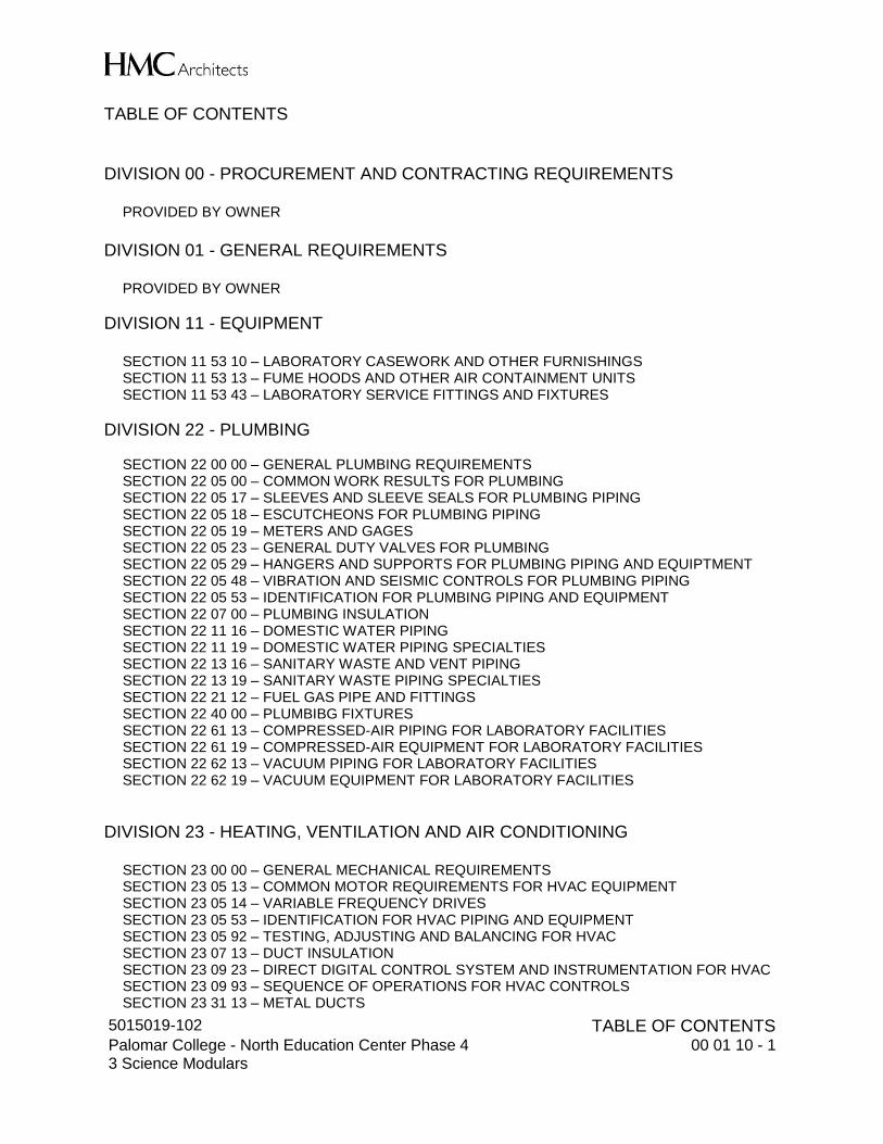
TABLE OF CONTENTS DIVISION 00 - PROCUREMENT AND CONTRACTING REQUIREMENTS
PROVIDED BY OWNER
DIVISION 01 - GENERAL REQUIREMENTS
PROVIDED BY OWNER
DIVISION 11 - EQUIPMENT
SECTION 11 53 10 – LABORATORY CASEWORK AND OTHER FURNISHINGS SECTION 11 53 13 – FUME HOODS AND OTHER AIR CONTAINMENT UNITS SECTION 11 53 43 – LABORATORY SERVICE FITTINGS AND FIXTURES
DIVISION 22 - PLUMBING SECTION 22 00 00 – GENERAL PLUMBING REQUIREMENTS SECTION 22 05 00 – COMMON WORK RESULTS FOR PLUMBING SECTION 22 05 17 – SLEEVES AND SLEEVE SEALS FOR PLUMBING PIPING SECTION 22 05 18 – ESCUTCHEONS FOR PLUMBING PIPING SECTION 22 05 19 – METERS AND GAGES SECTION 22 05 23 – GENERAL DUTY VALVES FOR PLUMBING SECTION 22 05 29 – HANGERS AND SUPPORTS FOR PLUMBING PIPING AND EQUIPTMENT SECTION 22 05 48 – VIBRATION AND SEISMIC CONTROLS FOR PLUMBING PIPING SECTION 22 05 53 – IDENTIFICATION FOR PLUMBING PIPING AND EQUIPMENT SECTION 22 07 00 – PLUMBING INSULATION SECTION 22 11 16 – DOMESTIC WATER PIPING SECTION 22 11 19 – DOMESTIC WATER PIPING SPECIALTIES SECTION 22 13 16 – SANITARY WASTE AND VENT PIPING SECTION 22 13 19 – SANITARY WASTE PIPING SPECIALTIES SECTION 22 21 12 – FUEL GAS PIPE AND FITTINGS SECTION 22 40 00 – PLUMBIBG FIXTURES SECTION 22 61 13 – COMPRESSED-AIR PIPING FOR LABORATORY FACILITIES SECTION 22 61 19 – COMPRESSED-AIR EQUIPMENT FOR LABORATORY FACILITIES SECTION 22 62 13 – VACUUM PIPING FOR LABORATORY FACILITIES SECTION 22 62 19 – VACUUM EQUIPMENT FOR LABORATORY FACILITIES
DIVISION 23 - HEATING, VENTILATION AND AIR CONDITIONING
SECTION 23 00 00 – GENERAL MECHANICAL REQUIREMENTS SECTION 23 05 13 – COMMON MOTOR REQUIREMENTS FOR HVAC EQUIPMENT SECTION 23 05 14 – VARIABLE FREQUENCY DRIVES SECTION 23 05 53 – IDENTIFICATION FOR HVAC PIPING AND EQUIPMENT SECTION 23 05 92 – TESTING, ADJUSTING AND BALANCING FOR HVAC SECTION 23 07 13 – DUCT INSULATION SECTION 23 09 23 – DIRECT DIGITAL CONTROL SYSTEM AND INSTRUMENTATION FOR HVAC SECTION 23 09 93 – SEQUENCE OF OPERATIONS FOR HVAC CONTROLS SECTION 23 31 13 – METAL DUCTS
5015019-102 TABLE OF CONTENTS
Palomar College - North Education Center Phase 4 3 Science Modulars
00 01 10 - 2
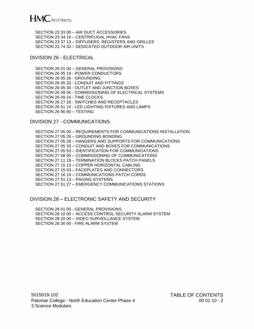
SECTION 23 33 00 – AIR DUCT ACCESSORIES SECTION 23 34 16 – CENTRIFUGAL HVAC FANS SECTION 23 37 13 – DIFFUSERS, REGISTERS AND GRILLES SECTION 23 74 33 – DEDICATED OUTDOOR AIR UNITS
DIVISION 26 - ELECTRICAL
SECTION 26 01 00 – GENERAL PROVISIONS SECTION 26 05 19 - POWER CONDUCTORS SECTION 26 05 26 - GROUNDING SECTION 26 05 33 - CONDUIT AND FITTINGS SECTION 26 05 34 - OUTLET AND JUNCTION BOXES SECTION 26 08 00 - COMMISSIONING OF ELECTRICAL SYSTEMS SECTION 26 09 24 - TIME CLOCKS SECTION 26 27 26 - SWITCHES AND RECEPTACLES SECTION 26 51 14 - LED LIGHTING FIXTURES AND LAMPS SECTION 26 90 90 – TESTING
DIVISION 27 - COMMUNICATIONS SECTION 27 05 00 – REQUIREMENTS FOR COMMUNICATIONS INSTALLATION SECTION 27 05 26 – GROUNDING BONDING SECTION 27 05 28 – HANGERS AND SUPPORTS FOR COMMUNICATIONS SECTION 27 05 33 – CONDUIT AND BOXES FOR COMMUNICATIONS SECTION 27 05 53 – IDENTIFICATION FOR COMMUNICATIONS SECTION 27 08 00 – COMMISSIONING OF COMMUNICATIONS SECTION 27 11 19 – TERMINATION BLOCKS PATCH PANELS SECTION 27 15 13 – COPPER HORIZONTAL CABLING SECTION 27 15 43 – FACEPLATES AND CONNECTORS SECTION 27 16 19 – COMMUNICATIONS PATCH CORDS SECTION 27 51 13 – PAGING SYSTEMS SECTION 27 51 27 – EMERGENCY COMMUNICATIONS STATIONS
DIVISION 28 – ELECTRONIC SAFETY AND SECURITY SECTION 28 01 00 - GENERAL PROVISIONS SECTION 28 10 00 – ACCESS CONTROL SECURITY ALARM SYSTEM SECTION 28 20 00 – VIDEO SURVEILLANCE SYSTEM SECTION 28 30 00 - FIRE ALARM SYSTEM
5015019-102 LABORATORY CASEWORK AND OTHER FURNISHINGS Palomar College - North Education Center, Phase 4 3 Science Modulars 11 53 10 - 1
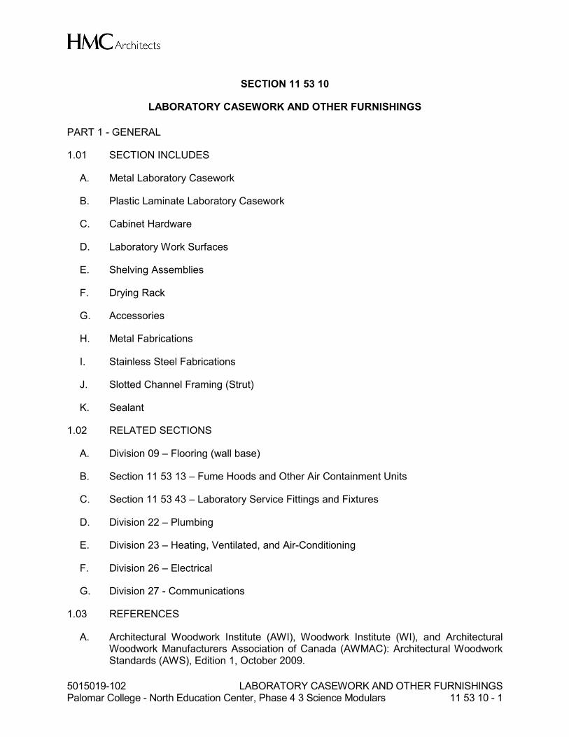
SECTION 11 53 10
LABORATORY CASEWORK AND OTHER FURNISHINGS
PART 1 - GENERAL
1.01 SECTION INCLUDES
A. Metal Laboratory Casework
B. Plastic Laminate Laboratory Casework
C. Cabinet Hardware
D. Laboratory Work Surfaces
E. Shelving Assemblies
F. Drying Rack
G. Accessories
H. Metal Fabrications
I. Stainless Steel Fabrications
J. Slotted Channel Framing (Strut)
K. Sealant
1.02 RELATED SECTIONS
A. Division 09 – Flooring (wall base)
B. Section 11 53 13 – Fume Hoods and Other Air Containment Units
C. Section 11 53 43 – Laboratory Service Fittings and Fixtures
D. Division 22 – Plumbing
E. Division 23 – Heating, Ventilated, and Air-Conditioning
F. Division 26 – Electrical
G. Division 27 - Communications
1.03 REFERENCES
A. Architectural Woodwork Institute (AWI), Woodwork Institute (WI), and Architectural Woodwork Manufacturers Association of Canada (AWMAC): Architectural Woodwork Standards (AWS), Edition 1, October 2009.

5015019-102 LABORATORY CASEWORK AND OTHER FURNISHINGS Palomar College - North Education Center, Phase 4 3 Science Modulars 11 53 10 - 2
B. Builders Hardware Manufacturers Association: ANSI/BHMA A156.18-2006 American National Standard for Materials and Finishes, 2006.
C. California Code of Regulations: Title 17, Section 93120: Airborne Toxic Control Measure to Reduce Formaldehyde Emissions from Composite Wood Products.
D. Hardwood Plywood & Veneer Association: ANSI/HPVA HP-1-2004 Standard for Hardwood and Decorative Plywood, 2004.
E. National Hardwood Lumber Association: NHLA Rules for the Measurement & Inspection of Hardwood & Cypress, 2007.
F. Scientific Equipment and Furniture Association: SEFA 2 Recommended Practices for the Installation of Scientific Laboratory Furniture and Equipment.
G. Scientific Equipment and Furniture Association: SEFA 3 Recommended Practices for Work Surfaces.
H. Scientific Equipment and Furniture Association: SEFA 8-M Recommended Practices for Laboratory Grade Metal Casework.
I. Scientific Equipment and Furniture Association: SEFA 8-PL Recommended Practices for Laboratory Grade Plastic Laminate Casework.
1.04 BID SUBMITTALS
A. Certification of Compliance: All bidders (including those listed in 2.01-A) must submit a compliance certification statement indicating that their bid includes products and installation which comply with every requirement of the project specifications and drawings (accounting for any RFI responses received during the bidding phase).
B. Certification of Qualifications: All bidders must submit a certification of compliance with the Qualifications requirements outlined below. List specific project experience as evidence of compliance.
C. Substitution Requests: All substitution requests for this scope of work in this section must be made during the bidding phase. No substitution requests will be considered post-bid.
1.05 SUBMITTALS
A. Refer to General Conditions and Division 1 “Submittal Procedures” for submittal requirements. In addition to these requirements, provide submittal requirements specified herein.
B. Submittal requirements: 1. Submittal shall be prepared individually for this specification section. Arrange
product data, drawings and information for submission in a complete set for this specification section.

5015019-102 LABORATORY CASEWORK AND OTHER FURNISHINGS Palomar College - North Education Center, Phase 4 3 Science Modulars 11 53 10 - 3
2. Submittal shall contain complete data for all items of this specification section. Periodic or partial submittals of individual components within this specification section will be returned as incomplete and rejected.
3. Submittals shall be organized by specification sequence with section and paragraph number identified.
4. Equipment and components being proposed shall be clearly labeled with all options and accessories indicated and shall be for this specific project. All non-applicable items shall be deleted or struck.
5. Product data submittals provided in PDF format shall consist of fully collated PDF files allowing for collated printing from a single file.
6. Shop drawings shall meet the requirements of the Architectural Woorworking Standards (AWS), except in cases where stricter requirements are identified in this section.
C. Materials List/Product Data: Submit complete materials list, including catalogue data, of all materials, equipment, and products for work in this section. 1. Product data shall not be duplicative or redundant with shop drawings. Do not
include drawings in the product data submittal that are included in the shop drawings.
D. Shop Drawings: Submit complete shop fabrication and installation drawings, including plans, elevations, sections, details and schedules. 1. Show relationship to adjoining materials and construction. 2. Show seaming pattern layout of all joints in work surfaces. 3. Shop Drawings shall be in the form of reproducible, PDF files, or photocopies, to
scale, sheet size not to exceed 11 inches x 17 inches (A3). 4. Shop drawing submittals provided in PDF format shall consist of fully collated files
allowing for collated printing from a single file. Blueline prints are not acceptable.
E. Approved Substitution/Approved Equal: In addition to the items required in Division 1, all substitution requests shall include item-by-item comparison of the proposed substitution to this project specification. A copy of the project specification shall be submitted, with each item and subsection of the project specification marked as “Comply” or “Not Comply.” In any cases where “Not Comply” is indicated, an explanation of the relative advantages of the proposed design shall be provided.
F. Submit detailed anchorage and attachment drawings and calculations provided by a licensed Structural Engineer complying with the Uniform Building Code Earthquake Regulations and the California Administrative Code, Title 24 Seismic Restraint requirements.
G. Samples: Accompanying Materials List, submit for Architect's approval two (2) samples of each type of specified finish and color range available for casework, laboratory work surfaces, painted steel fabrications, cabinet hardware, and shelving.
H. Certifications/ Test Data: Submit certifications and test data as required elsewhere in this section, including SEFA structural performance test reports, and finish performance test reports.
I. Operations/Maintenance Manuals: At project close-out, submit for Architect's review and Owner's use, complete operating and maintenance manuals that describe proper
5015019-102 LABORATORY CASEWORK AND OTHER FURNISHINGS Palomar College - North Education Center, Phase 4 3 Science Modulars 11 53 10 - 4
operating procedures, maintenance and replacement schedules, components parts list, and closest factory representative for components and service.
J. Warranty: Submit manufacturer’s warranty including any additional certifications as needed to meet the requirements specified.
1.06 PRODUCT HANDLING
A. Protection: Use all means necessary to protect work of this section before, during and after installation including installed work and materials of other trades.
B. Replacement: Any damaged work shall be replaced, repaired and restored to original condition to the approval of the Architect at no additional cost or inconvenience to the Owner.
1.07 ENVIRONMENTAL CONDITIONS
A. It is the responsibility of the general contractor or construction manager to provide appropriate environmental conditions within the laboratory spaces throughout the period of installation of wood and composite wood casework products until substantial completion of the project and turnover to the owner. The relative humidity standards as delineated by the Architectural Woodwork Standards should be followed. 1. Humidity must be controlled between 25% and 55% in all areas where laboratory
casework is stored and/or installed. 2. The range of relative humidity change should not exceed 30 percentage points.
B. It is the responsibility of the laboratory furniture subcontractor to assess building environmental conditions prior to the delivery and installation of laboratory casework. Wood laboratory casework shall not, under any circumstances, be installed in spaces which do not comply with the requirements outlined above.
1.08 QUALIFICATIONS
A. Work in this section shall be manufactured by and installed by a company/companies having a minimum of eight years documented experience providing and installing products similar to those specified in laboratory applications; an established organization; and production facilities including all tools, equipment and special machinery necessary for specializing in the fabrication and installation of the type of products specified, with skilled personnel, factory trained workmen and an experienced engineering department. Each shall have the demonstrated knowledge, ability and the proven capability to produce the specified work of the required quality and the proven capacity to complete an installation of this size and type within the required time limits.
1.09 ENVIRONMENTAL COMPLIANCE
A. Composite Wood Products – Composite wood products shall comply with the California Code of Regulations: Title 17, Section 93120: Airborne Toxic Control Measure to Reduce Formaldehyde Emissions from Composite Wood Products. 1. The definition of composite wood products, as applied to this requirement, shall
be those as defined in the regulation cited.

5015019-102 LABORATORY CASEWORK AND OTHER FURNISHINGS Palomar College - North Education Center, Phase 4 3 Science Modulars 11 53 10 - 5
2. Comply with the limitations scheduled for enforcement at the time of sale and manufacturing, accounting for the grace periods allowed by the regulation.
3. Provide documentation, certification, and labelling as required by the regulation.
1.10 WARRANTY
A. All products will be warranted to be free from defects in materials and workmanship for a period of two years following substantial completion. The manufacturer/dealer/subcontractor shall repair or replace any products (or parts thereof) that are found to be defective. Replacement will include any parts, labor, shipping, and travel expenses involved. Warranty replacement work must be scheduled in coordination with the client’s academic/research schedule and may therefore require evening and/or weekend work.
PART 2 - PRODUCTS
2.01 METAL LABORATORY CASEWORK
A. Manufacturers: Products complying with this specification may be provided by the following manufacturers. All products specified in this section shall be the provided by a single manufacturer. Corrosive and flammable liquid/solvent storage cabinets may also be provided by the manufacturers listed with their descriptions. 1. Laboratory Casework:
a. Air Master Systems, 6480 Norton Center Drive, Muskegon, MI 49441 Tel 231 798-1111.
b. Bedcolab Ltd, 2305 Francis Hughes Avenue, Laval, Quebec, Canada H7S 1H5 Tel 514 384-2820.
c. CiF Lab Solutions, 53 Courtland Avenue, Vaughan, Ontario, Canada L4K 3T2 Tel: 905 738-5821.
d. ICIscientific, 1865 Highway 641 North, Paris, TN 38242-8814 Tel: 731-642-4251.
e. Kewaunee Scientific Corporation, P O Box 1842, Statesville, NC 28687 Tel: 704 873-7202.
f. Mott Manufacturing Ltd., 452 Hardy Road, P. O. Box 1120, Brantford, ON, Canada N3T 5T3 Tel: 519 752-7825
g. Approved substitution.
B. Metal Laboratory Casework 1. Design Requirements:
a. Door and drawer front design: Square edged inset metal construction with all front surfaces above the toe space in the same plane.
b. Pulls on doors shall be mounted vertically and on drawers horizontally. c. All cabinets shall be constructed and finished to be suitable for use as
stand-alone units and to permit future rearrangement without the need for additional parts or finish.
d. Widths of drawers in knee opening rails shall not be less than 24 inches (600 mm) or the width of the rail whichever is the lesser.
e. Cabinets below fume hoods that conflict with ductwork, cup sinks, or waste connections shall be 19 inches deep to accommodate any obstructions.
5015019-102 LABORATORY CASEWORK AND OTHER FURNISHINGS Palomar College - North Education Center, Phase 4 3 Science Modulars 11 53 10 - 6
a). Provide metal filler panels at inside corners, end-of-run conditions, and other similar locations, aligned with the face of adjacent metal cabinet bodies.
2). Outside corners: a). At outside corners, align the side panel of cabinet with the
cabinet body of adjacent cabinet. 2. Materials:
a. Steel: Cold-rolled furniture stock sheet steel, prime grade, roller leveled. 1). Steel shall be treated at the mill to be free of scale, ragged edges,
deep scratches, or other injurious effects. 2). All gauges indicated are to be U.S. standard.
3. Base Cabinets: a. General:
1). Exterior corners: shall be spot and arc welded with heavy back up reinforcement at exterior corners. All face joints shall be arc welded and ground smooth to provide a continuous flat plane.
2). All units shall have a cleanable smooth interior. Front and rear posts, reinforcing members or channel uprights shall be enclosed full heights on all cabinet openings.
3). End Uprights shall be formed into not less than a channel formation at top, bottom, back and front.
4). The edge of the vertical uprights shall be formed to provide a strike for doors and drawers, and shall be perforated for the support of drawer channels, intermediate rails and hinge screws.
5). An upright filler shall be screwed in place in all cupboard units to close the back of the channel at front of the upright and to provide a smooth interior for the cupboard to facilitate cleaning.
6). The upright filler shall be perforated with shelf adjustment holes at no more than ½ inch (12.7 mm) centers.
7). The inside front of the upright shall be further reinforced with a full height 14 gauge (2.0 mm thick) hinge reinforcement angle.
8). Die Formed Gussets: shall be furnished in each bottom corner of base units to insure rigidity, and a 3/8 inch (10 mm) -16 leveling bolt, 3 inches (75 mm) long, shall engage a clinch nut in each gusset. Each leveling bolt and gusset shall be capable of supporting 500 lbs (225 kg). (Each unit shall support 2000 lbs. (900 kg) uniformly distributed on a work top.) Provide caps at all penetrations provided to access leveling devices.
b. Cabinet Base: 1). Case bottom and bottom rail shall be formed of one piece of metal
except in corner units and shall have both sides and back formed up or down and shall be offset in front to provide a door and drawer recess rabbet.
2). Toe Space Rail: shall extend up and forward to engage bottom rail to form a smooth surfaced toe space, 3 inches (75 mm) deep and 4 inches (100 mm) high. Whenever the base is omitted for units to be set on building bases or separate metal bases, the toe space rail shall extend back 4½ inches (115 mm).
c. Cabinet Back, Unexposed: Cabinet back shall consist of a top and bottom rail, channel formed for maximum strength and welded to back and top flange
5015019-102 LABORATORY CASEWORK AND OTHER FURNISHINGS Palomar College - North Education Center, Phase 4 3 Science Modulars 11 53 10 - 7
of end uprights, with space between left open for access to plumbing lines. All units shall be provided with removable back panels. 1). Sink units shall be provided with fixed half-height backs to allow
plumbing lines to enter and exit the cabinet through the open area. d. Doors: shall be readily removable and hinges easily replaceable. Hinges
shall be applied to the case and door with screws. Welding of hinges to either case or door will not be acceptable.
e. Doors: 1). Metal, Flush Inset: shall be a two-piece sheet steel assembly of ¾ inch
(19 mm) overall thickness to consist of an inner pan formed as an extension of the drawer body, an outer pan having a channel formation on all four sides, and the interior space filled with a non-organic sound deadening material at the time of assembly. Door Pans and Drawer Heads shall be painted inside and out prior to assembly. a). All four corners of door and drawer heads shall be welded closed
and ground smooth to eliminate exposure of raw edges and open gaps.
f. Top Horizontal Rail: Provide on base cabinets such that rail shall interlock within the flange at top of end panels for strength. Reinforcements shall be provided at all front corners for additional welded strength between vertical and horizontal case members.
g. Knee Space Service Strip Cover Panels where specified, shall be 18 gauge (1.3 mm thick) steel, of the same finish as cabinets, and shall be furnished at open spaces under counter top where no cabinets occur. They shall be easily removable and shall cover piping from underside of top of service ledge to floor.
h. Provide filler panels where required between cabinets, at corner intersections of cabinets, between cabinets and walls and wherever else required for a complete finished installation. Filler panels shall follow the profile of toe kicks.
i. Leveling Glides and Leg Shoes: 1). Each leg other than those fitted with casters shall have leveling glides:
(2 inch) (48 mm) diameter, two-piece pivot construction, steel housing, non-marring, phenolic or translucent plastic insert, (1/2 inch) (12 mm) diameter, minimum (1 1/2 inch) (36 mm) long zinc plated stems. Each glide shall have a load bearing capacity of 150 lbs.
2). Each leg other than those fitted with casters and adjustable-height legs, shall have leg shoes: Black coved vinyl or rubber leg shoe, 2 inches (50 mm) in height.
4. Aprons and leg assemblies: a. Apron: Not less than 1½ inch (38 mm) x 4 inch (114 mm) 16 gauge (x 1.6
mm thick) channel steel sections, reinforced as necessary for leg attachment. b. Legs: Not less than 2 inch (50 mm) x 2 inch (50 mm) 16 gauge (x 1.6 mm
thick) square tubular steel sections. c. Leg rails: Not less than 1¼ inch (32 mm) x 2½ inch (63 mm) 16 gauge (x 1.6
mm thick) steel sections, reinforced as necessary for leg attachment. Each leg shall have a recessed leveling screw and a black, coved vinyl or rubber leg shoe, 2 inches (50 mm) in height.
5. Fume Hood Cabinets: a. Purpose-designed metal cabinet with fixed panel above door to conceal cup
sink and plumbing.
5015019-102 LABORATORY CASEWORK AND OTHER FURNISHINGS Palomar College - North Education Center, Phase 4 3 Science Modulars 11 53 10 - 8
b. Provide metal fume hood cabinets where adjacent cabinetry below a fume hood is also metal.
6. Corrosives Storage Cabinets: a. Manufacturers:
1). Manufacturers of metal laboratory casework (base cabinets only). 2). Justrite Manufacturing Company, 2454 Dempster St., Suite 300, Des
Plaines, IL 60016 Tel: 800 798-9250. 3). Approved substitution.
b. Purpose-designed lined metal cabinet. c. Lining (Base Cabinets only): Cabinet shall be complete lined with a
polypropylene or polyethylene liner with sealed or seamless intersections between panels. Liner shall be the full depth of the cabinet. No metal of any type shall be exposed within the lined interior of the cabinet. Screw-heads, if required, shall be covered with hinged-type (not snap-on) plastic screw-head covers. 1). Shelf: Removable full-depth polypropylene or polyethylene shelf. Full-
depth is defined as a shelf whose front edge is within ½ inch (13mm) of the face of the cabinet when the shelf is fully back in the cabinet.
d. Lining (Tall Cabinets only): All interior surfaces of the cabinet shall be coated with a 100% seamless non-porous flame-coated thermoplastic liner. Liner shall be applied to all interior walls, ceiling, sump, door interiors, and shelving. Basis of design: Justrite Chemcor. No known equal. 1). Shelf: Removable adjustable full-depth metal shelf coated with lining
material. Full-depth is defined as a shelf whose front edge is within ½ inch (13mm) of the face of the cabinet when the shelf is fully back in the cabinet.
2). Refer to drawings for number of shelves required. e. Label: "CORROSIVES" in conspicuous silk-screened lettering. Stick-on
decals are not acceptable. Size and style of lettering shall match the Flammable Liquid/Solvent Storage Cabinet label. Lettering shall be 2 ½ inches tall. Color of lettering shall be red. If cabinet color is red, lettering shall be yellow.
f. Locks: Cabinet doors shall be lockable where indicated. Lock shall have not metal parts exposed within the lined interior.
g. Venting: 1). Cabinets below or adjacent to fume hoods: Provide and install 2 inch
(50 mm) diameter schedule 40 PVC vent pipe and PVC fittings. Termination of vent pipe maybe one of the following: a). Extend vent pipe 4 inches (100 mm) above dished worktop,
behind the baffle in the hood, as shown on the drawings. Provide hole through fume hood work surface above the corrosive storage cabinet to accommodate 2 inch (50 mm) diameter vent pipe. Seal gap around penetration with clear silicone sealant.
b). Extend vent pipe up within the fume hood side wall and vent through the hood side wall liner behind the upper portion of the fume hood baffle.
2). Cabinets not below or adjacent to fume hoods: Vent connection to exhaust duct system shall be by Division 23. Provide hole in back of cabinet to accept exhaust connection.
h. Seismic Anchor: Provide seismic anchor for freestanding cabinets and cabinets located below fume hoods designated to be removable for access

5015019-102 LABORATORY CASEWORK AND OTHER FURNISHINGS Palomar College - North Education Center, Phase 4 3 Science Modulars 11 53 10 - 9
for persons with disabilities. Seismic anchors may be floor or wall attachments, but shall not attach to adjacent casework or work surfaces. Seismic anchors shall be accessible without removal of laboratory casework, furnishings, or equipment.
7. Flammable Liquid/Solvent Storage Cabinets: a. Manufacturers:
1). Manufacturers of metal laboratory casework (base cabinets only). 2). Eagle Manufacturing Company, 2400 Charles St., Wellsburg, WV
26070 Tel: 304 737-3171. 3). Justrite Manufacturing Company, 2454 Dempster St., Suite 300, Des
Plaines, IL 60016 Tel: 800 798-9250. 4). Approved substitution.
b. Purpose-designed double-walled metal cabinet for the storage of flammable, combustible and solvent liquids.
c. Cabinet doors: Well-fitting, metal, self-closing and self-latching with fusible lead links and door sequencer.
d. Label: "FLAMMABLE - KEEP FIRE AWAY" in conspicuous silk-screened lettering. Stick-on decals are not acceptable. Size and style of lettering shall match that of the Corrosive Storage Cabinet label. “FLAMMABLE” lettering shall be 2 ½ inches tall. “KEEP FIRE AWAY” lettering shall be 2 inches tall. Color of lettering shall be red. If cabinet color is red, lettering shall be yellow.
e. Locks: Cabinet doors shall be lockable. f. Floor pan: Provide a 2 inch (50 mm) deep liquid tight pan to cover the entire
bottom of the cabinet to contain liquid leaks and spills. g. Shelves: Provide heavy-duty full-depth metal shelves using pan-type
construction to create a liquid-tight containment tray. Refer to drawings for quantity of shelves.
h. Standards: 1). Comply with the requirements of OSHA and NFPA 30. 2). Comply with the requirements of Uniform Fire Code and the
International Fire Code with with UL 1275 and FM 6050 labels. i. Flammable liquid/solvent storage cabinets shall not be vented. Seal vent
openings with bungs as provided by manufacturer. j. Electrical grounding:
1). Provide each flammable liquid / solvent storage cabinet with an externally mounted grounding conductor screw terminal for up to #8 AWG conductor, mounted at the top of the cabinet.
2). Connection from the equipment grounding bus at the lab branch circuit panel to the storage cabinet terminal shall be by Division 26.
k. Seismic Anchor: Provide seismic anchor for freestanding cabinets and cabinets located below fume hoods designated to be removable for access for persons with disabilities. Seismic anchors may be floor or wall attachments, but shall not attach to adjacent casework or work surfaces. Seismic anchors shall be accessible without removal of laboratory casework, furnishings, or equipment. Anchor attachment shall not void UL listing.
8. Metal Casework Construction Performance: Base cabinets shall be constructed to support a uniformly distributed load of 200 lbs. minimum per square foot (1000 kg/m²) of cabinet top area (total maximum of 2000 lbs. (900 kg)), including working surface without objectionable distortion or interference with door and drawer operation.
5015019-102 LABORATORY CASEWORK AND OTHER FURNISHINGS Palomar College - North Education Center, Phase 4 3 Science Modulars 11 53 10 - 10
a. Base cabinet corner gussets with leveling bolts shall support 500 lbs. (225 kg) per corner, at 1½ inch (38 mm) projection of the leveling bolt below the gusset.
b. Each adjustable and fixed shelf 4 feet (1219 mm) or shorter in length shall support an evenly distributed load of 40 lbs. per square foot (200 kgf/m²) up to a maximum of 200 lbs. (90 kg), with nominal temporary deflection, but no permanent set.
c. Swinging doors mounted on base units shall support a 250 lb. (113 kg) load located at a test point 14 inches (356 mm) measured horizontally from hinge along the top edge of door through a swing of 180 degrees. Weight test shall allow nominal temporary deflection, but no permanent distortion. Door assembly shall be twist- resistant and rigid, and shall close in a flat plane against the cabinet to permit the door catch at top of door to function properly.
C. Hardware: As specified elsewhere in this Section.
D. Metal Casework Color: As selected by the Architect from manufacturer's full color line and complying with finish requirements described below.
E. Metal Casework Finish Requirements: 1. Paint finish for steel laboratory products shall utilize a dry coating process with
minimal waste generation. Liquid-applied coatings shall not be acceptable. Manufacturer shall supply documentation that waste generated during the painting process, is a solid, non-hazardous material. a. Pretreatment: Finish process shall incorporate a phosphate conversion
coating during the pretreatment/cleaning operation. b. Operator Protection: The painting process shall be cleanly contained, have
no solvent odor and be performed in an air-conditioned room. c. VOC (Volatile Organic Compounds) emissions shall not exceed 0.29 lbs per
gallon (35 g/L). d. Offgasing: No further emissions or “Offgasing/Decomposition” vapors shall
occur at room temperature from installed finished parts. 2. Preparation: After the units have been completely welded together and before
finishing, they shall be given a pre-paint treatment to provide excellent adhesion of the finish to the metal and to aid in the prevention of corrosion. Physical and chemical cleaning of the metal shall be accomplished by washing with an alkaline cleaner, followed by a spray treatment with a heated cleaner/phosphate solution and pretreated with iron phosphate spray followed by a neutral final seal prior to application of final finish. The strength of each solution shall be monitored by filtration to insure consistent quality. All treated parts shall be immediately dried in heated ovens and gradually cooled before application of the finish. Treated metal parts shall be clean and properly prepared to provide optimum adhesion of finish and resistance to corrosion.
3. Application: Electrostatically apply powder coat of selected color and bake in controlled high temperature oven to assure a smooth, hard satin finish. Surfaces shall have a chemical resistant, high grade laboratory furniture quality finish of the following thicknesses: a. All surfaces, exterior or interior, exposed to view, shall receive sufficient
powder coat to achieve an average 1.5 mil (38 µm) film thickness with a minimum 1.2 mil (30 µm) film thickness and shall have smooth satin luster.
5015019-102 LABORATORY CASEWORK AND OTHER FURNISHINGS Palomar College - North Education Center, Phase 4 3 Science Modulars 11 53 10 - 11
b. Backs of cabinets and other surfaces not exposed to view shall have sufficient powder coat to achieve an average 1.0 mil (25 µm) film thickness.
4. All drawer bodies to be finished in matching color or in a uniform neutral color. 5. Concealed interior parts shall receive corrosion-resistant treatment. 6. Finish must be UV stable.
F. Metal Finish Performance Requirements: 1. Manufacturer shall submit metal finish performance testing results. Testing to be
performed by independent testing agency. 2. Chemical resistance:
a. Test procedure: Place samples on a flat surface, clean with soap and water and blot dry. Condition the panel for 48-hours at 73+ 3F (23(+ 2(C) and 50+ 5% relative humidity, or the currently accepted guideline set by ASTM. Test the samples for chemical resistance using forty-nine different chemical reagents by one of the following methods. For both methods, leave the reagents on the sample for a period of one hour. Wash off the sample with water, clean with detergent and naptha, and rinse with deionized water. Dry with a towel and evaluate after 24-hours at 73± 3°F (23°± 2°C) and 50± 5% relative humidity, or the currently accepted guideline set by ASTM 1). Method A: Test volatile chemicals by placing a cotton ball saturated
with reagent in the mouth of a 1-oz. (29.574cc) bottle and inverting the bottle on the surface of the sample. The cotton ball shall remain in contact with the sample for the duration of the test.
2). Method B: Test non-volatile chemicals by placing five drops of the reagent on the surface of the sample and covering with a 24mm watch glass, convex side down.
b. Rating System: Evaluations shall use the following rating system:
Level 0 No detectable change. Level 1 Slight change in color or gloss. Level 2 Slight surface etching or severe staining. Level 3 Pitting, cratering, swelling, or erosion of coating.
Obvious and significant deterioration.
c. Acceptance Level: 1). Individual test results for the specified 49 reagents shall be within the
Range for that reagent as specified on the table below. 2). There shall be no more than four (4) Level 3 conditions.
d. Table of reagents:
Test No.
Chemical Reagent Test Method Range
1. Acetate, Amyl A 0-1 2. Acetate, Ethyl A 0-2 3. Acetic Acid, 98% B 0-3 4. Acetone A 0-1 5. Acid Dichromate, 5% B 0-1 6. Alcohol, Butyl A 0-1 7. Alcohol, Ethyl A 0-1 8. Alcohol, Methyl A 0-1 9. Ammonium Hydroxide, 28% B 0
10. Benzene A 0-2 11. Carbon Tetrachloride A 0-1
5015019-102 LABORATORY CASEWORK AND OTHER FURNISHINGS Palomar College - North Education Center, Phase 4 3 Science Modulars 11 53 10 - 12
Test No.
Chemical Reagent Test Method Range
12. Chloroform A 0-2 13. Chromic Acid, 60% B 0-2 14. Cresol A 0-2 15. Dichloroacetic Acid A 0-3 16. Dimethylformamide A 0-2 17. Dioxane A 0-2 18. Ethyl Ether A 0-1 19. Formaldehyde, 37% A 0-1 20. Formic Acid, 90% B 0-3 21. Furfural A 0-3 22. Gasoline A 0 23. Hydrofluoric Acid, 37% B 0-2 24. Hydrofluoric Acid, 48% B 0-3 25. Hydrogen Peroxide, 30% B 0-1 26. Iodine, Tincture of B 0-2 27. Methyl Ethyl Ketone A 0-2 28. Methylene Chloride A 0-2 29. Monochlorobenzene A 0-2 30. Naphthalene A 0-1 31. Nitric Acid, 20% B 0-1 32. Nitric Acid, 30% B 0-1 33. Nitric Acid, 70% B 0-3 34. Phenol, 90% A 0-2 35. Phosphoric Acid, 85% B 0-1 36. Silver Nitrate Saturated B 0 37. Sodium Hydroxide 10% B 0 38. Sodium Hydroxide 20% B 0 39. Sodium Hydroxide 40% B 0-1 40. Sodium Hydroxide Flake B 0 41. Sodium Sulfide Saturated B 0 42. Sulfuric Acid, 33% B 0 43. Sulfuric Acid, 77% B 0 44. Sulfuric Acid, 96% B 2-3 45. Sulfuric Acid 77% & Nitric Acid
70% equal parts B 1-3
46. Toluene A 0-1 47. Trichloroethylene A 0-1 48. Xylene A 0-1 49. Zinc Chloride, Saturated B 0
3. Hot Water Test a. Test Procedure: 190°F to 205°F (88°C to 96°C) hot water shall be allowed to
trickle (with a steady stream and at a rate of not less than 6 ounces (177.5 cc) per minute) on the finished surface, which shall be set at an angle of 45°, for a period of 5 minutes.
b. Acceptance Level: After cooling and wiping dry, the finish shall show no visible effect from the hot water.
4. Paint Adhesion on Steel Test

5015019-102 LABORATORY CASEWORK AND OTHER FURNISHINGS Palomar College - North Education Center, Phase 4 3 Science Modulars 11 53 10 - 13
a. Test Procedure: Test shall be based on ASTM D2197-86 “Standard Method of Test for Adhesion of Organic Coating.” Two sets of eleven parallel lines 1/16 inch (1.587 mm) apart shall be cut with a razor blade to intersect at right angles thus forming a grid to 100 squares. The cuts shall be made just deep enough to go through the coating, but not into the substrate. Brush surface lightly with a soft brush for one minute. Examine under 100 fc (1076 lux) of illumination.
b. Acceptance Level: Ninety or more of the squares shall show finish intact. 5. Impact Test
a. Test Procedure: Drop a 1 lb (0.4536 kg) ball (approximately 2 inch (50.8 mm) diameter from a distance of 12 inches (305 mm) onto a flat horizontal surface, coated to manufacturer’s standard manufacturing method.
b. Acceptance Level: No visual evidence to the naked eye of cracks in the finish due to impact.
6. Paint Hardness on Steel Test a. Test Procedure: Paint film shall be tested with pencils of various hardnesses.
Pencils shall have a wide, sharp edge. Pencils shall be pushed across surface in a chisel-like manner.
b. Acceptance Level: Finish film shall not rupture from a sharpened 4H pencil.
2.02 PLASTIC LAMINATE LABORATORY CASEWORK
A. Manufacturers: Products complying with this specification may be provided by the following manufacturers. All products specified in this section shall be the provided by a single manufacturer. 1. Caseworx, 1130 Research Drive, Redlands, CA 92374 Tel: 909 799-8550. 2. CiF Lab Solutions, 53 Courtland Avenue, Vaughan, Ontario, Canada L4K 3T2 Tel:
905 738-5821. 3. LSI Corporation of America, Inc., 2100 Xenium Lane, Minneapolis, MN 55441 Tel:
612 559-4664. 4. Pacific Cabinets, Inc., 2010 Front Street, Ferdinand, ID 83526-0081 Tel: 208 962-
5546. 5. TMI System Design Corporation, 50 South Third Avenue West, Dickinson, ND
58601 Tel: 701 225-6716. 6. Approved substitution.
B. Design Requirements: 1. Door and drawer design: Square edged full flush overlay design with 1/8 inch (3
mm) horizontal reveals and 3/8 inch vertical reveals. 2. Pulls on doors shall be mounted vertically and on drawers horizontally. 3. For plastic laminate materials with directional patterns, pattern shall run in the
same orientation across all cabinet door and drawer fronts, filler panels, and flush panels. Laminate pattern shall align on all surfaces of a cabinet front.
4. Full-Flush Construction and Installation: All finished panels shall be in the same plane to provide a true flush overlay appearance. a. Flush panels: Provide fixed fully-edgebanded flush panels so that all finished
panels are in the same plane as cabinet doors and drawers to provide a true flush overlay appearance. 1). End-of-run filler panels are required at all conditions where the joint
width is one inch or larger.
5015019-102 LABORATORY CASEWORK AND OTHER FURNISHINGS Palomar College - North Education Center, Phase 4 3 Science Modulars 11 53 10 - 14
b. Applied panels may be required in areas such as sink cabinets and knee opening aprons to complete the flush construction.
c. At outside corners, align side panel of cabinet with the face of the door of adjacent cabinet.
d. At inside corners, mount filler panels flush with face of adjacent cabinet doors.
e. At open cabinets (without doors), align face of cabinet with face of adjacent cabinet door.
f. Align other filler panels with face of adjacent cabinet doors. g. Filler panels shall follow the profile of toe kicks.
5. Flush interiors: Set cupboard bottom flush with front end facers. Surface mounted bottoms and offsets caused by front face frames which interfere with ease of cleaning are not acceptable.
6. Drawer fronts at knee openings to be full width of apron and drawer box to be widest possible width. Provide two drawers at units wider than 30 inches.
C. Performance Requirements: 1. Meet all performance requirements of SEFA-8-PL.
D. Materials: 1. Plastic Laminate:
a. Grade VGS: High pressure decorative laminate, finely ground textured finish, meeting or exceeding NEMA Standard LD3 2005, Grade VGS Grade CLS: High pressure cabinet liner. High pressure decorative laminate, finely ground textured finish, meeting or exceeding NEMA Standard LD3.1 2005 Grade CLS.
b. Grade BKL: Backing sheets. High pressure phenolic meeting or exceeding NEMA Standard LD3 2005, Grade BKL.
c. Low Pressure Cabinet Liner: Low pressure decorative laminate. Thermally fused melamine or polyester impregnated papers, meeting or exceeding the requirements of NEMA Standard LD3 2005.
2. Core Material: a. Typical, Unless Otherwise Noted: Hardwood veneer core plywood.
1). Description: A one step calibrated core +/- .5mm (to avoid voids) with type 1 waterproof nauf glue. Grade 2 face, and back of mill choice, veneer core plywood.
2). Thickness/Plies: a). ¾ inch (19 mm): minimum 7-ply. b). 1 inch (25 mm): minimum 9-ply.
3). Physical Properties: a). Average modulus of rupture: 7346 psi (50.65 N/mm2). b). Face Screw Holding Strength: 355 lbf (1579 N).
b. Drawer and Door Fronts: ANSI A208.1 M3 Grade Industrial Particleboard Core. 1). Screwholding: Minimum 247 lbs at face, 225 pounds at edge. 2). Modulus of rupture: Minimum 2,393 lb/in2. 3). Modulus of elasticity: Minimum 389,900 lb/in2. 4). Hardness: Minimum 500 lbs.
3. Hardboard:
5015019-102 LABORATORY CASEWORK AND OTHER FURNISHINGS Palomar College - North Education Center, Phase 4 3 Science Modulars 11 53 10 - 15
a. Tempered hardboard designed for strength and moisture resistance, consisting of wood fibers, highly compressed into a hard, dense, ¼ inch (6 mm) thick, homogenous sheet using natural resins and other binders.
b. Provide melamine-clad hardboard typically. c. Physical Properties:
1). Average modulus of rupture: 5300 psi (36,540 kPa). 2). Density: 50 to 60 lb/ft3 (800 to 960 kg/m3). 3). Tensile strength: 3500 psi (24,100 kPa).
4. Laminate Adhesive: Polyvinyl acetate or thermosetting adhesive applied in accordance with NEMA LD 3.1-1995. Contact adhesive is not acceptable.
5. Dowels: 8-10 mm, diameter, minimum, hardwood, laterally fluted with chamfered ends.
6. Edge Banding: a. 3 mm PVC: Doors and drawer fronts typically. Provide at cabinet edges
where indicated in this specification. T-Mold is not acceptable b. 0.018 inch (0.5 mm) PVC: Other exposed cabinet body edges. c. All PVC edge banding shall be applied with hot melt adhesive. Contact
cement is not acceptable. 7. Metal Parts: Metal parts, table legs, post legs, counter supports, etc., shall be
furniture steel, fabricated by welding, then degreased, cleaned, treated and painted to match casework finish and color.
8. Colors for all materials, metal parts and hardware shall be selected by the Architect from the manufacturer's full color line.
E. Definition of cabinet components by surface visibility: 1. Exposed Surfaces:
a. All surfaces exposed when doors and drawers are closed, unless otherwise noted.
b. Interior faces of cabinet door and drawer fronts. c. All exterior surfaces of suspended and mobile casework. d. Bottoms of cabinets if 42 inches (1070 mm) or more above finished floor. e. Tops of cabinets if less than 72 inches (1830 mm) above finished floor. f. Front rail of web frames. g. Knee opening aprons. h. ADA sink apron enclosures. i. All visible surfaces of end panels. j. Tops of cabinets 72 inches (1830 mm) or more above finished floor when
visible from an upper level. k. Filler panels and flush panels.
2. Semi-exposed surfaces: a. Surfaces that are visible when solid (opaque) doors are open. b. Surfaces that are visible when drawers are extended. c. Surfaces visible when behind glass doors, including tops and bottoms of
shelves. d. Inside of open units, including top and bottom of shelving.
3. Unexposed surfaces: a. Surfaces not normally visible after installation with doors open and drawers
extended. b. Bottoms of cabinets less than 30 inches (750 mm) above finished floor. c. Tops of cabinets over 78 inches (1980 mm) above finished floor and not
visible from an upper level.
5015019-102 LABORATORY CASEWORK AND OTHER FURNISHINGS Palomar College - North Education Center, Phase 4 3 Science Modulars 11 53 10 - 16
F. Fabrication: 1. Laminates:
a. Exposed Surfaces: Chemical resistant high-pressure decorative laminate (HPDL).
b. Semi-Exposed Surfaces: Chemical resistant high-pressure decorative laminate (HPDL).
c. Unexposed Surfaces: Except as noted otherwise, backing sheets or melamine, as appropriate for substrate, resulting in balanced panel construction.
2. Cabinet Joinery: Tops and bottoms shall be joined to cabinet ends using a minimum of 6 dowels for 24 inch (610 mm) deep cabinets and a minimum of 5 dowels for 14 inch (356 mm) deep cabinets. All dowels are to be hardwood, laterally fluted, with chamfered ends and a minimum diameter of 8 mm. Internal cabinet components such as fixed horizontals, rails and verticals are to be doweled in place. Dowels are to be securely glued and cabinets clamped under pressure during assembly to assure secure joints and cabinet squareness. No upright of any kind shall be used at the center of double door cabinets.
3. Base, Wall, Upper, and Tall Cases: a. Base Cabinet Top: Full sub-tops (rails not acceptable). ¾ inch (18 mm) thick
core material fully laminated on the interior surface with a balancing laminate on the unexposed top. All tops shall be solid except for sink base tops, which have a vertical sub front reinforcement panel. Rabbet top to accept back panel.
b. Base Cabinet Bottom: ¾ inch (18 mm) thick core material fully laminated on the interior surface with a balancing laminate on the unexposed bottom.
c. Cabinet Ends, Sides, and Backs Exposed from the Outside: Fully-laminated ¾ inch (18 mm) thick core material. Holes shall be drilled for adjustable shelf clips 1¼ inches (32 mm) on center. Bore ends to accept doweled top and bottom. Rabbet ends and sides to accept recessed back.
d. Cabinet Back, Unexposed from the Outside: 1). Standard cabinet back:
a). ¼ inch (6 mm) thick hardboard with inside laminated to match interior of cabinet, with balancing laminate on the back side.
b). Housed on 4 sides, sealed with hot melt adhesive. c). Reinforce with ¾ x 3½ inch (19 x 89 mm) spreaders secured with
glue and screws. 2 spreaders are required at base and wall cabinets, 3 spreaders are required at tall cabinets.
2). Base cupboard and base drawer cabinet backs: a). ¼ inch (6 mm) thick hardboard with inside laminated to match
interior of cabinet, with balancing laminate on the back side. b). Back panels easily removable from interior for access to service
lines - fixed backs are not acceptable. c). Provide split back on drawer cabinets. d). All sink cabinets to have half-height fixed backs to allow for
plumbing and sink waste connections. e. Cabinet Base: Provide all base and tall cabinets, knee space and filler panels
with a separate and continuous base of core material of ladder-type construction - front, back and intermediates. Finish all base surfaces, which are exposed prior to the application of the resilient base, with laminate to match the casework. Provide concealed fastening to cabinet body. Top-set
5015019-102 LABORATORY CASEWORK AND OTHER FURNISHINGS Palomar College - North Education Center, Phase 4 3 Science Modulars 11 53 10 - 17
resilient base at all exposed casework and all knee spaces to be provided under Division 9.
f. Shelves: 1 inch (25 mm) thick full depth. Full-depth is defined as a shelf whose front edge is within ½ inch (13mm) of the face of the cabinet when the shelf is fully back in the cabinet. 1). Front edge of shelves shall be edgebanded. 2). Front edge of open shelves:
a). PVC Safety Edging: 2 inches (50 mm) tall x 3 mm thick PVC edge banding.
3). All shelves shall be full-depth. Full-depth is defined as a shelf whose front edge is within ½ inch (13mm) of the face of the cabinet when the shelf is fully back in the cabinet.
4). Shelf adjustment: All shelves shall be adjustable on 32 mm centers. 5). Shelf tolerance: Shelves shall fit into cabinet body or into shelf
supports with a maximum tolerance of 1/16 inch per side. g. Doors and Drawer Heads: ¾ inch (18 mm) thick core material fully laminated.
All corners shall be square and all edges finished with 3 mm PVC edge banding, radiused and buffed inside and out, machine-radiused corners.
h. Drawer Construction: 1). Sides, back and sub-front shall be ½ inch (12 mm) thick core material,
laminated. Top edge shall be banded with PVC edging. Sides shall be full height with ½ inch (13 mm) clearance to frame opening. Drawers shall extend within 2 inches (50mm) of the cabinet back.
2). Acceptable drawer joinery options: a). Dowel: Glued under pressure; 32mm, minimum, dowel spacing
to 4 inches (102 mm) high, 64 mm dowel spacing above 4 inches (102 mm).
b). Lock Shoulder: Glued and pin nailed. 3). Drawer bottoms shall be either:
a). ½ inch (12 mm) thick core material, laminated, screwed directly to the bottom edges of the drawer box.
b). 6mm white melamine-clad hardboard. Bottom shall be grooved into the 4 sided drawer box and sealed with hot melt glue process around entire drawer bottom perimeter. The bottoms of drawer over 24 inches (610 mm) in width shall be reinforced with ½ x 3 inch (12 x 75 mm) stiffeners, 1 @ 24 inches (610 mm), 2 @ 36 inches (914 mm), 4 @ 48 inches (1219 mm).
4). Security Panels: Provide hardboard security panels, 1/8 inch (3 mm) thick, when keyed-different locks are specified, or where individual padlock hasps are indicated. Inset security panel into frame on all four sides. Provide intermediate back rail of 1½ inch (38 mm) x ¾ inch (19 mm) thick laminated core material to accept hardboard security panel between locked compartments and drawers.
i. Provide edgebanded fixed flush panels at sink cabinets, knee opening drawer units, filler panels, and elsewhere, so that all finished panels are in the same plane as cabinet doors and drawers to provide a true flush overlay appearance.
j. Knee Space: Knee space panels shall be ¾ inch (18 mm) thick core material, laminated with vertical surface high pressure laminate on the exposed side and with a high pressure cabinet liner on the reverse. Edgeband bottom surface of knee opening rail. Back panels shall be removable to provide clear

5015019-102 LABORATORY CASEWORK AND OTHER FURNISHINGS Palomar College - North Education Center, Phase 4 3 Science Modulars 11 53 10 - 18
access to the service zone from the top of the fixed continuous toe space base (see Toe Space below) to the underside of the work surface. When knee openings occur against walls, provide end panel at wall.
k. Base unit front horizontal intermediate rail: ¾ inch (19 mm) x 1½ inches (38 mm) rail shall be provided between doors and drawers. For all drawer units at benches where piping occurs, intermediate horizontal and vertical box frames must be removable. These components shall be assembled with Keku suspension fittings as manufactured by Häfele America Co. or approved so these members are easily removable at any time with no special tools to gain access to concealed piped services behind.
l. Security Panels: Provide 1/8 inch-thick hardboard security panels in frames between drawers and cabinets within a cabinet where keyed different locks are indicated, or where individual padlock hasps are indicated. Inset security panel into frame on all four sides.
m. Tall Storage Cabinets: Swinging door storage cases shall present a smooth exterior to be suitable for free standing installation. Internal reinforced cabinet sides shall contain shelf clip adjustment holes. All units shall have fixed back and double doors. No upright of any type shall be used at the center of double door units.
n. Provide filler panels where required between cabinets, at corner intersections of cabinets, between cabinets and walls and wherever else required for a complete finished installation. For tall cabinets, filler panels shall be provided for vertical face and top. For wall cabinets, filler panels shall be provided for vertical face, top and bottom.
G. Hardware: As specified elsewhere in this Section.
2.03 CABINET HARDWARE
A. General: Special cabinets, such as corrosives storage, flammable liquid and solvent storage, rock storage, map storage, museum storage, radioisotope storage, and narcotics lockers, may be provided with the manufacturer’s standard hardware. 1. All door and drawer pulls shall match, regardless of type of casework, except for:
a. Polypropylene casework. Refer to the pull requirements as specified above. b. Flammable liquid/ solvent storage cabinets, which should use manufacturer’s
standard latch handles as required to satisfy requirements of regulatory approvals.
2. All hardware shall be compliant with the ADA Standards for Accessible Design (28 CFR Part 36).
B. Drawer and Hinged Door Pulls: 1. Drawer and door pulls shall attach to door or drawer with machine screws. Two (2)
pulls shall be furnished on drawers wider than 28 inches (711 mm). Plastic pulls or other types subject to breakage are not acceptable.
2. Type: Pulls shall be round “wire.” a. Material and Finish:
1). Stainless steel with finish as follows: a). BHMA 630 Satin (Previously US32D).
b. Size: 1). Length: 4 inches (100 mm) center to center of screw holes. 2). Diameter: ¼ inch (6 mm).
5015019-102 LABORATORY CASEWORK AND OTHER FURNISHINGS Palomar College - North Education Center, Phase 4 3 Science Modulars 11 53 10 - 19
C. Hinges: 1. General: Hinges shall be attached to both door and case with three screws through
each leaf. Provide two hinges for doors up to 48 inches (1219 mm) high; three hinges for doors over 48 inches (1219 mm) high.
2. Type: Institutional with a five-knuckle bullet-type barrel. Characteristics: a. Height: 2½ inches (63 mm), nominal. b. Material: Stainless steel with stainless steel screws.
1). Finish: a). BHMA 630 Satin (Previously US32D).
2). Manufacturers: a). Rockford Process Control, Inc. 202 Seventh St., Rockford, IL
61104 Tel: 815 966-2000. b). Approved substitution.
D. Shelf Hardware: 1. Shelf Supports:
a. Adjustable shelf supports: Adjustable clear plastic shelf support with lockdown clips.
2. Manufacturers: a. Bainbridge Manufacturing, Inc., P. O. Box 487, 237 W 3rd, Waterville, WA
98858 Tel: 800 255-4702. b. The Engineered Products Company (Epco), P. O. Box 108, Flint, MI 48501
Tel: 313 767-2050. c. Knape & Vogt Manufacturing CO., 2700 Oak Industrial Dr. NE, Grand
Rapids, MI 49505 Tel: 616 459-7620. d. Sugatsune America, Inc. 221 East Selandia Lane, Carson, CA 90746 Tel:
310 329-6373. e. Approved substitution.
E. Catches: 1. Roller Catches:
a. Types and Materials: Roller catches shall be one of the following types. All-plastic or knuckle-type catches are not acceptable, except at corrosive storage cabinets. 1). Tension ball catches consisting of a case with an adjustable-tension
ball catch and a matching strike. Components shall be either stainless steel, chrome plated zinc alloy, or chrome-plated brass.
2). Nylon roller housed in a steel case, which catches on a steel strike plate. Steel components shall be zinc finished.
3). At metal casework base cupboard, catches may consist of a two-piece heavy-duty cam action positive catch positioned near the pivoting edge of door which provides a clean unobstructed opening. Main body of the catch shall be confined within an integral cabinet divider rail, while latching post shall be mounted on the hinge side of door.
4). At corrosive storage cabinets, catches shall be non-metallic. b. Application: Provide roller catches at all cabinet doors without elbow catches.
1). At wall and base cabinets locate roller catches at top of cabinet door. 2). At tall cabinets, locate roller catch to fixed center shelf.
c. Manufacturers: 1). The Engineered Products Company (Epco), P. O. Box 108, Flint, MI
48501 Tel: 313 767-2050.
5015019-102 LABORATORY CASEWORK AND OTHER FURNISHINGS Palomar College - North Education Center, Phase 4 3 Science Modulars 11 53 10 - 20
2). Sugatsune America, Inc. 221 East Selandia Lane, Carson, CA 90746 Tel: 310 329-6373.
3). Approved substitution. 2. Elbow catches: Heavy-duty, adjustable, spring-type elbow catch and strike plate.
a. Material: Brass or steel with bright chromium plated finish. b. Application: Elbow catches shall be used on left hand doors of locked double
door cabinets, including tall cabinets. 1). At tall cabinets, elbow catch shall latch to fixed center shelf. Latching
devices using chains or strings are not acceptable. c. Manufacturers:
1). The Engineered Products Company (Epco), P. O. Box 108, Flint, MI 48501 Tel: 313 767-2050.
2). Approved substitution.
F. Drawer slides: 1. Typical: Ball bearing slides:
a. Material: 1). Clear, zinc-coated steel.
b. Full extension, 100 lb/pr. (45 kg/pr.) capacity: Accuride 3832, Fulterer FR5000, or equal.
c. File drawers shall be equipped with rail mounted with overtravel, 150 lb/pr. (68 kg/pr.) capacity: Accuride 4034, Fulterer 5755, or equal.
G. Special Hardware Requirements for Mobile Cabinets: 1. Mobile cabinets shall be engineered by the manufacturer to avoid overturning
(tipping) when drawers are loaded to their design load, and opened to the specified glide opening.
2. The top drawer of mobile cabinets shall have an opening restricted to ¾ full open. 3. Mobile cabinets shall be provided with a rod-based drawer interlock glide system
to prevent multiple drawers from being opened simultaneously. Accuride 3641 with companion slides Accuride 3642, Fulterer FR5218 with companion slides FR5019, or similar.
4. Mobile cabinets may additionally be provided with a counter weight system, consisting of galvanized steel plates securely attached to the cabinet bottom or inside the cabinet back. The weights shall not be visible when the cabinet is in the normal, upright position.
H. Drawer Stops: All regular drawers shall be equipped with integral stops to prevent drawer head impact with cabinet body.
I. Door Stops: Provide door stops for any cabinet door, which will strike an obstruction when opened between 90° and 135°. 1. Stop to be either:
a. Sash chain, #30 zinc-plated steel. 1). Terminations: Zinc chromate wire screw eyes. Open eye as required
to attach stop with screws. Through-bolting not allowed. b. Coated cable.
1). Seven-strand, 7-wire-per-strand, stainless steel cable with clear nylon coating.
2). Wire diameter: 0.047 inches. 3). Composite diameter with coating: 0.063 inches.
5015019-102 LABORATORY CASEWORK AND OTHER FURNISHINGS Palomar College - North Education Center, Phase 4 3 Science Modulars 11 53 10 - 21
4). Terminations: Number 10 stake eye on both ends. Attach to door/cabinet with screws. Through-bolting not allowed.
5). McMaster Carr part number 30345T3 or equivalent. 2. Engineer stop to length to allow door to open 1 ½ inch (40 mm) from obstruction.
J. Hanging File Suspension System: Hangers shall be fastened and secured to drawer construction and shall not be freestanding units set inside the drawer. Provide in all file drawers. 1. Basis of Design: Blum Metafile Hanging File Frame Kit. 2. Manufacturers:
a. Julius Blum, Inc. 7733 Old Plank Rd., Stanley, NC 28164 Tel: 800 438-6788. b. Hettich America L. P., 6225 Shiloh Rd., Alpharetta, GA 30005 Tel: 800 438-
8424. c. Approved substitution.
K. Label holders: Provide label holders, pinned in place. Stick-on holders not acceptable. Label holders shall be provided at all file drawers, and elsewhere as shown on drawings. 1. Size:
a. Minimum Size: 1 inch (25mm) x 2 inches (50mm) b. Maximum Size: 2 inches (50mm) x 3 ½ inches (90mm)
2. Material and finish: a. Steel with matt chrome finish.
3. Basis of Design Product: a. 704ANO Label Holder by Knape & Voght, 2700 Oak Industrial Drive NE,
Grand Rapids, MI 49505 Tel: 800 253-1561. b. Approved substitution.
L. Number Plates: Provide 5/8 inch (16 mm) x 1 ¼ inches (32 mm) aluminum number plates with black numbers, pinned in place. Stick-on holders not acceptable. Number plates shall be provided at all drawers where indicated on the plans. Number drawers sequentially in each laboratory.
M. Locks: 1. General: Provide locks on all file cabinet drawers. Provide locks at other locations
as indicated on the drawings. 2. Lock type: Deadbolt-type lock.
a. Disc-tumbler-type locks and/or cam-type locks will not be accepted. b. Framed sliding door locks shall be plunger type. c. Refer to Elbow Catches section, above, for requirements at two-swinging-
door cabinets. 3. Testing requirements:
a. Locks shall comply with ANSI/BHMA standard E07121. b. Lock shall be cycle tested per ANSI/BHMA A156.11 Grade 1.
4. Include spacers, adapters, fasteners, and strikes. a. All locks shall strike into metal material. Striking directly into wood is not
acceptable. 5. Barrel length shall be coordinated with specific conditions. 6. Finish: Locks shall have satin nickel or satin chrome finish. 7. Keying:
a. Key quantities: Provide two keys per lock. Provide four copies of any master/ grand master keys.
5015019-102 LABORATORY CASEWORK AND OTHER FURNISHINGS Palomar College - North Education Center, Phase 4 3 Science Modulars 11 53 10 - 22
b. Key system: 1). Key system shall support a minimum of 2000 different keys. 2). Key system shall support up to three levels of master keys (grand-
master keys, master keys, and sub-master keys) in addition to individual keys.
c. Key cylinder type: 1). Coordinate key type with owner.
d. Key schedule: Coordinate key schedule with Owner. 8. Key engraving:
a. Keys to be engraved with an identification number corresponding to the layout of unique keys on the project. All identical keys shall be engraved with the same number.
b. At laboratories with multiple, individually-locked drawers where number plates are indicated, engrave each key with number to match the number plate on each drawer.
9. Manufacturers: a. Swinging Doors and Drawers:
1). Illinois Lock Company, 301 West Hintz Rd., Wheeling, IL 60090 Tel: 847 537-1800.
2). National Cabinet Lock, 200 Old Mill Rd., P. O. Box 200, Mauldin, South Carolina 29662 Tel: 864 297-6655.
3). Olympus Lock, Inc. 18424 Highway 99, Lynnwood, Washington 98037 Tel: 206 362-3290.
4). Approved substitution.
N. Padlock Hasps: Provide one of the following: 1. Stainless-steel padlock-eye cam-type locking device and strike plate at cabinet
locations as indicated on the drawings. Strike plate, or protection plate, shall be large enough to prevent padlock from damaging door or drawer front.
2. Barrel-style cam-type padlock hasp sized to fit standard lock cylinder hole with finish to match drawer pulls, and strike plate at cabinet locations as indicated on the drawings. Strike plate, or protection plate, shall be large enough to prevent padlock from damaging door or drawer front.
3. Cam-lock shall engage or strike into a metal casting. 4. Manufacturers:
a. Northeast Lock Corporation, 48 Oak St., Clifton, NJ 07014 Tel: 800 524-2575.
b. Olympus Lock, Inc. 18424 Highway 99, Lynnwood, Washington 98037 Tel: 206 362-3290.
c. Rockford Process Control, Inc. 202 Seventh St., Rockford, IL 61104 Tel: 815 966-2000.
d. Approved substitution.
O. Glides: Non-marring material, 1 inch (25 mm) diameter, minimum, with at least 5/8 (16 mm) vertical adjustment. Provide on movable tables, unless otherwise indicated.
P. Leveling devices: Provide each table leg with 3/8 inch (10 mm) minimum diameter leveling bolt and floor clip.
Q. Leg shoes: Leg shoes shall be provided on all legs and table legs to conceal leveling devices, except for tables with casters. Shoes shall be 2 ½ (63 mm) inch high and of

5015019-102 LABORATORY CASEWORK AND OTHER FURNISHINGS Palomar College - North Education Center, Phase 4 3 Science Modulars 11 53 10 - 23
black rubber or pliable black vinyl material. Use of a leg shoe which does not conceal leveling device is not acceptable.
R. Floor clips: Provide leg assemblies and fixed table legs with floor clips securely fastened to the floor after shimming.
S. Casters: Where indicated on Laboratory Furnishing drawings, provide sets of 3 ½ inch (89 mm) diameter wheels with self-lubricating bearing, rated to carry 250 pounds (113 kg) minimum each. Each caster must swivel and have a locking brake. Wheel shall be of molded polyurethane tread mechanically locked to a polyolefin core. 1. Material: Caster shall be heavy gauge cold rolled steel with bright zinc plating.
T. Support Struts and Service Ledging: Refer to specifications for slotted channel framing in this Section.
2.04 LABORATORY WORK SURFACES
A. Epoxy Resin: 1. Manufacturers: Products complying with this specification may be provided by the
following manufacturers. a. American Epoxy Scientific, 500 East 16th Street, Mountain Home, AR 72653
Tel: 870-425-7777. b. Durcon Laboratory Tops, Inc., 206 Allison Drive, Taylor, TX 76574 Tel: 512
595-8000. c. Kewaunee Scientific Corporation, P O Box 1842, Statesville, NC 28687
Tel: 704 873-7202. d. Approved substitution.
2. Thickness: a. Typical work surface: 1 inch (25 mm). b. Fume hood work surfaces: Tops shall be 1¼ (32 mm) inches thick at outer
edge, indented minimum ¼ inch (6 mm) to provide a raised rim around all exposed edges 1 inch (25 mm) wide, minimum, or as to allow for the fume hood sash. The front top edge of the raised rim and exposed vertical corners of the top shall be rounded or chamfered to a 1/8 inch (3 mm) radius. The juncture between the raised rim and the top surface shall be coved or chamfered to a ¼ inch (6 mm) radius.
c. Curbs and Splashes: ¾ inch (19 mm). 3. Color:
a. Black. b. Color sample to be approved by Architect before work is put in hand.
4. Description: a. Monolithic filled epoxy resin work surface consisting of a polymerized cast
resin material oven-cured in molds. b. Drip Grooves: Provide under all work surface exposed edges, unless noted
otherwise on the Laboratory Furnishing Drawings. Drip grooves shall be ½ inch (13 mm) from the front edge where the top overhangs 1 inch (25 mm) and ¼ inch (6 mm) from the edge where the edge overhangs ½ inch (13 mm).
c. Edge profile: For all exposed upper edges and corners: 1). Bevel eased: 1/8 inch (3 mm) machined bevel with blended radius
corners.
5015019-102 LABORATORY CASEWORK AND OTHER FURNISHINGS Palomar College - North Education Center, Phase 4 3 Science Modulars 11 53 10 - 24
d. Sink Mounting: 1). Drop-in Sink Cutouts: Cutouts shall be profiled to provide support for
the sink, and to ensure that the rim of the installed sink is 1/8 inch (3 mm) below the surrounding work surface level or bottom of drain grooves, if present. The top edge of the cutout shall have 1/8 inch (3 mm) bevel. Ensure that there shall be no gaps between the installed sink rim and work surface.
e. Curbs and Splashes: 1). Height: 4 inches (100 mm), unless noted otherwise on Laboratory
Furnishing Drawings. 2). Bonded to the surface of the top to form a square joint.
f. Provide all holes and cutouts as required for built-in equipment and mechanical and electrical service fixtures. Verify size of opening with actual size of equipment to be used prior to making openings. Form inside corners to a radius of not less than 1/8 inch (3 mm). After sawing, rout and file cutouts to ensure smooth, crack-free edges. Seal exposed edges after cutting with a waterproofing material recommended by the manufacturer.
g. Provide full-length, one-piece tops and backsplashes wherever possible, and keep field joints to an absolute minimum.
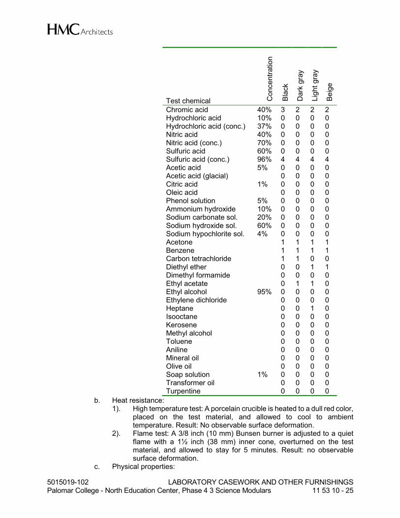
5. Physical Properties: a. Chemical resistance:
1). Organic solvents: A cotton ball, saturated with the test chemical, is placed in a one ounce bottle with a reservoir of liquid above the ball. The container is inverted on the test material surface for a period of 24 hours. Test temperature: 23°C ±2°C.
2). Other test chemicals: Five drops (1/4 cc) of the test chemical are placed on the test material surface. The chemical is covered with a 1 inch diameter watch glass for a period of 24 hours. Test temperature: 23°C ±2°C.
3). Evaluation: After 24 hours exposure, exposed areas are washed with water, then a detergent solution, finally with naphtha, then rinsed with distilled water, dried with a cloth, and rated as follows:
0 No effect No detectable change in the material surface.
1 Excellent Slight detectable change in color or gloss but no change in function or life of the surface.
2 Good A clearly discernable change in color or gloss but no significant impairment of surface life or function.
3 Fair Objectionable change in appearance due to discoloration or etch, possibly resulting in deterioration of function over an extended period of time.
4 Failure Pitting, cratering, or erosion of the surface. Obvious and significant deterioration.
4). Test results:
5015019-102 LABORATORY CASEWORK AND OTHER FURNISHINGS Palomar College - North Education Center, Phase 4 3 Science Modulars 11 53 10 - 25
Test chemical Concentr
ation
Bla
ck
Dark
gra
y
Lig
ht
gra
y
Beig
e
Chromic acid 40% 3 2 2 2 Hydrochloric acid 10% 0 0 0 0 Hydrochloric acid (conc.) 37% 0 0 0 0 Nitric acid 40% 0 0 0 0 Nitric acid (conc.) 70% 0 0 0 0 Sulfuric acid 60% 0 0 0 0 Sulfuric acid (conc.) 96% 4 4 4 4 Acetic acid 5% 0 0 0 0 Acetic acid (glacial) 0 0 0 0 Citric acid 1% 0 0 0 0 Oleic acid 0 0 0 0 Phenol solution 5% 0 0 0 0 Ammonium hydroxide 10% 0 0 0 0 Sodium carbonate sol. 20% 0 0 0 0 Sodium hydroxide sol. 60% 0 0 0 0 Sodium hypochlorite sol. 4% 0 0 0 0 Acetone 1 1 1 1 Benzene 1 1 1 1 Carbon tetrachloride 1 1 0 0 Diethyl ether 0 0 1 1 Dimethyl formamide 0 0 0 0 Ethyl acetate 0 1 1 0 Ethyl alcohol 95% 0 0 0 0 Ethylene dichloride 0 0 0 0 Heptane 0 0 1 0 Isooctane 0 0 0 0 Kerosene 0 0 0 0 Methyl alcohol 0 0 0 0 Toluene 0 0 0 0 Aniline 0 0 0 0 Mineral oil 0 0 0 0 Olive oil 0 0 0 0 Soap solution 1% 0 0 0 0 Transformer oil 0 0 0 0 Turpentine 0 0 0 0
b. Heat resistance: 1). High temperature test: A porcelain crucible is heated to a dull red color,
placed on the test material, and allowed to cool to ambient temperature. Result: No observable surface deformation.
2). Flame test: A 3/8 inch (10 mm) Bunsen burner is adjusted to a quiet flame with a 1½ inch (38 mm) inner cone, overturned on the test material, and allowed to stay for 5 minutes. Result: no observable surface deformation.
c. Physical properties:

5015019-102 LABORATORY CASEWORK AND OTHER FURNISHINGS Palomar College - North Education Center, Phase 4 3 Science Modulars 11 53 10 - 26
Compressive strength ASTM D695 31,400 psi (216 MPa)
Tensile strength ASTM D638 8,000 psi (55 MPa) Flexural strength ASTM D790 11,700 psi (81 MPa) Rockwell hardness “M” ASTM D785 105-110 Specific density ASTM D792 122.4 lb/ft³ (1960
kg/m³) Water absorption ASTM D570 0.01% Fire Resistance ASTM D635 ATB (sec)=0 Heat deflection @ 264 psi (1.82 MPa)
ASTM D648 205°F (172°C)
2.05 SHELVING ASSEMBLIES
A. High-Pressure Decorative (Plastic) Laminate Shelving: 1. Manufacturers/Facing material: Products complying with this specification may be
provided by the following manufacturers. a. Nevamar Decorative Surfaces, One Nevamar Place, Hampton, SC 29924
Tel: 800 638-4380. b. Pionite Decorative Surfaces, One Pionite Road, P.O. Box 1014, Auburn, ME
04211 Tel: 800 746-6483. c. Wilsonart International, 2400 Wilson Place, P. O. Box 6110, Temple, TX
76503 Tel: 800 433-3222. d. Approved substitution (no known equal).
2. Approved Products: a. Nevamar ChemArmor. b. Pionite ChemGuard. c. Wilsonart ChemSurf
3. Color: To be selected by Architect. 4. Description:
a. High-pressure decorative laminate, meeting or exceeding NEMA Standard LD3 2005 Grade HGP, HGL, or HGS requirements, consisting of a resin formulation applied over the decorative surface paper to achieve chemical resistance. The decorative paper shall be treated with melamine resin, and the core shall consist of kraft papers impregnated with phenolic resin. Sheets shall be bonded under high temperature and pressure. Product shall be developed for casework, work surface, and shelving surfaces in laboratories.
b. Laminate shall be applied to top and bottom surfaces. c. Finish: Fine pebble-grained “crystal” texture or matte texture with slight
sheen to minimize smudges and finger marks, and to provide optimum scratch resistance. 1). Gloss: 15-16 +/- 3 gloss units.
d. Physical Properties: 1). Reference Standard: Plastic laminates shall meet or exceed
ANSI/NEMA Specification LD3-2005 as specified herein. 2). Minimum Thickness: 0.038 inches ± 0.005 inches (0.97 mm ± 0.13
mm). 3). Cleanability: 10 cycles (NEMA LD3 test method 3.4). 4). Boiling Water Resistance: No effect (NEMA LD3 test method 3.5). 5). High Temperature Resistance: Slight effect (NEMA LD3 test method
3.6).

5015019-102 LABORATORY CASEWORK AND OTHER FURNISHINGS Palomar College - North Education Center, Phase 4 3 Science Modulars 11 53 10 - 27
6). Scratch Resistance: 4.5 Newtons (NEMA LD3 test method 3.7). 7). Ball Impact Resistance: 60 inches (1524 mm) (NEMA LD3 test method
3.8). 8). Radiant Heat Resistance: 200 sec (NEMA LD3 test method 3.10). 9). Dimensional change: 10). Machine direction: 0.50% (NEMA LD3 test method 3.11). 11). Cross direction: 0.80% (NEMA LD3 test method 3.11). 12). Wear resistance: 1,500 cycles, min. (black); 700 cycles, min. (other
colors) (NEMA LD3 test method 3.13). 13). Blister Resistance: 70 sec (NEMA LD3 test method 3.15). 14). Stain Resistance Performance Test Results: The surface shall show
essentially no effect on Black (Lab grade) plastic laminate when left in contact for 16 hours either when reagents were kept covered or allowed to evaporate.
0 No effect No detectable change in the material surface.
1 Excellent Slight detectable change in color or gloss but no change in function or life of the surface.
2 Good A clearly discernable change in color or gloss but no significant impairment of surface life or function.
3 Fair Objectionable change in appearance due to discoloration or etch, possibly resulting in deterioration of function over an extended period of time.
4 Failure Pitting, cratering, or erosion of the surface. Obvious and significant deterioration.
Acids C
oncentr
ation
Rating
Acetic acid All 0 Aqua regia 0 Chromic trioxide (Chromic acid cleaning solution)
1
Glacial acetic acid 99% 0 Hydrochloric acid All 0 Hydrofluoric acid 48% 0 Formic acid All 0 Nitric acid All 3 Sulfuric acid All 0 Perchloric acid (concentrated) 0 Phosphoric acid All 0 Picric acid 1.2% 0
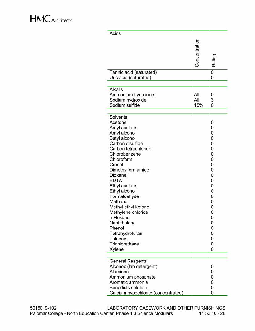
5015019-102 LABORATORY CASEWORK AND OTHER FURNISHINGS Palomar College - North Education Center, Phase 4 3 Science Modulars 11 53 10 - 28
Acids
Concentr
ation
Rating
Tannic acid (saturated) 0 Uric acid (saturated) 0
Alkalis Ammonium hydroxide All 0 Sodium hydroxide All 3 Sodium sulfide 15% 0
Solvents Acetone 0 Amyl acetate 0 Amyl alcohol 0 Butyl alcohol 0 Carbon disulfide 0 Carbon tetrachloride 0 Chlorobenzene 0 Chloroform 0 Cresol 0 Dimethylformamide 0 Dioxane 0 EDTA 0 Ethyl acetate 0 Ethyl alcohol 0 Formaldehyde 0 Methanol 0 Methyl ethyl ketone 0 Methylene chloride 0 n-Hexane 0 Naphthalene 0 Phenol 0 Tetrahydrofuran 0 Toluene 0 Trichlorethane 0 Xylene 0
General Reagents Alconox (lab detergent) 0 Aluminon 0 Ammonium phosphate 0 Aromatic ammonia 0 Benedicts solution 0 Calcium hypochlorite (concentrated) 0

5015019-102 LABORATORY CASEWORK AND OTHER FURNISHINGS Palomar College - North Education Center, Phase 4 3 Science Modulars 11 53 10 - 29
General Reagents Camphorated parachlorophenol 1 Cellosolve 0
Copper sulfate 0 Ethylene glycol 0 Eucalyptol 0 Formalin 0 Gasoline 0 Hydrogen peroxide 3% 0 Iodine 0 Karl Fisher Reagent 0 Kerosene 0 Lactated ringers 0 Lysol 0 Methyl methacrylate 0 Mineral Oil 0 Monsel’s solution (Ferric subsulfate) 0 Naphtha 0 Petroleum jelly 0 Phosphate buffered saline (PBS) 0 Pine oil 0 Potassium permanganate 0 Povidone iodine 0 Procaine 0 Quaternary ammonia compounds 0 Silver nitrate 0 Sodium azide 0 Sodium chromate 0 Sodium hypochlorite 5% 0 Sodium thiocyanate 0 Sucrose 50% 0 Thymol & Alcohol 0 Tincture of Iodine 0 Tincture of Mercurochrome 0 Tincture of Merthiolate 0 Trisodium phosphate 30% 0 Urea 0 Vegetable oils 0 Water 0 Zephiran chloride 0 Zinc chloride 0 Zinc oxide ointment 0
Stains and Indicators Ag Eosin Bluish 5% in Alcohol 0 Bromothymol Blue 0 Cresol Red 0 Crystal Violet 0 Gentian Violet 1% 0 Gram Stains 0

5015019-102 LABORATORY CASEWORK AND OTHER FURNISHINGS Palomar College - North Education Center, Phase 4 3 Science Modulars 11 53 10 - 30
Stains and Indicators Malachite Green 0 Methyl Orange 0 Methyl Red 0 Methylene Blue 0 Nigrosine 0 Safranin O 0 Sudan III 0 Thymol Blue 0 Wright’s Blood Stain 0
5. Plastic laminate adhesive: High-pressure decorative laminate shall be bonded to core with thermosetting resorcinol or phenol-resorcinol adhesive, or as recommended by the manufacturer for the application, at temperature above 65°F (18.3°C) at a pressure no less than 15 pounds per square inch. Laminate core is not to exceed 10% moisture content and is to be laminated and cured in a controlled environment between 45% and 60% RH.
6. Core material: Hardwood Veneer Plywood. a. Description: A one step calibrated core +/- .5mm (to avoid voids) with type 1
waterproof nauf glue. Grade 2 face, and back of mill choice plywood veneer. b. Thickness/Plies:
1). 1 inch (25 mm): minimum 9-ply. c. Physical Properties:
1). Average modulus of rupture: 7346 psi (50.65 N/mm2). 2). Face Screw Holding Strength: 355 lbf (1579 N).
7. Edging: a. Unless otherwise indicated, all edges shall be edgebanded with 3 mm PVC
edge banding set in hot melt adhesive. Adhesive shall have a minimum softening point of 150°F (65.6°C). Apply primer to substrate when recommended by adhesive manufacturer. Contact cement is not acceptable. Color of edgebanding to be selected by the Architect.
B. Safety Edges: 1. Types:
a. Extended Height PVC Band: 2 inch high set in hot melt adhesive. Adhesive shall have a minimum softening point of 150°F (65.6°C). Apply primer to substrate when recommended by adhesive manufacturer. Contact cement is not acceptable.
2. Refer to the description of each system below for locations of each type.
C. Adjustable Wall Shelves: 1. Shelving: High-Pressure Decorative Laminate shelving as specified above. 2. Double Slot Shelf Standards:
a. Manufacturers: Products complying with this specification may be provided by the following manufacturers. All products specified in this section shall be the provided by a single manufacturer. 1). Knape & Vogt Manufacturing Company, 2700 Oak Industrial Drive NE,
Grand Rapids, MI 49505 Tel: 616 459-3311. 2). Approved substitution.
b. Basis of Design: Knape & Vogt 85 ANO series uprights, or equal. Length as indicated on the drawings.
3. Shelf Brackets: 16 gauge (1.6 mm) bookend type, as detailed on drawings.

5015019-102 LABORATORY CASEWORK AND OTHER FURNISHINGS Palomar College - North Education Center, Phase 4 3 Science Modulars 11 53 10 - 31
4. Safety edging: a. Front Edge:
1). Extended height PVC band. 5. Load capacity: System shall support a minimum of 35 pounds per square foot
applied at all shelves simultaneously. Maximum deflection shall be 0.35 inches (9mm) under load.
6. Finish: Factory finish standards and brackets with epoxy powder coating. Color to be selected by the Architect.
D. Open Industrial Metal Shelf Units: 1. Manufacturers: Products complying with this specification may be provided by the
following manufacturers. All products specified in this section shall be the provided by a single manufacturer. a. Lyon Metal Products, P. O. Box 671, Aurora, IL 60507 Tel: 800 323-0096. b. Penco Products, Inc., P. O. Box 378, 99 Brower Ave., Oaks, PA 19456 Tel:
800 562-1000. c. Hallowell, Division of List Industries Inc., 5711 Distribution Dr., Memphis, TN
38141 Tel: 901 375-0022. d. Approved substitution.
2. Type: Premium grade 18 gauge (1.0 mm thick) steel shelf units comprised of 5 shelves adjustable on 1 ½ inch (38 mm), maximum, increments, and 85 inches (2159 mm) high 14 gauge (2.0 mm thick) angle post supports. Size in accordance with Laboratory Furnishings plans.
3. Provide side and rear cross bracing for lateral stability at freestanding applications.
2.06 DRYING RACK
A. Stainless Steel Drying Rack with White Polypropylene Pegs: 1. Manufacturers: Products complying with this specification may be provided by the
following manufacturers. All products specified in this section shall be the provided by a single manufacturer. a. Inter Dyne Systems, Inc., 676 Ellis Road, Norton Shores, MI 49441 Tel: 231
799-8760. b. Approved substitution (no known equal).
2. Basis of Design: Inter Dyne Systems “V” Victoria Series, modified as indicated on the drawings. a. Drying rack bodies shall be of one-piece design and of not less than 20 gauge
(1.0 mm thick) Type 304 stainless steel with a No. 4 finish. The top shall have two 90-degree bends, and sides to have one 90 degree bend.
b. Each rack shall have an integral full-width 20 gauge (1.0 mm thick), Type 304 stainless steel drip trough with stainless steel drain tube. Drip trough shall be continuously welded.
c. The trough shall have a full-length, Type 304 stainless steel wire mesh screen insert. Screen insert shall be turned down on all four sides to provide a clean and finished appearance.
d. Each rack front shall be dimensioned and punched with T-shaped holes to accommodate the peg arrangement shown on the drawings.
3. Pegs shall fit into the punched holes in the rack front. A T-shaped protrusion on the base of the pegs shall allow easy removal and replacement without the need for tools. The T-shaped holes shall be designed to fit the protrusion on support
5015019-102 LABORATORY CASEWORK AND OTHER FURNISHINGS Palomar College - North Education Center, Phase 4 3 Science Modulars 11 53 10 - 32
pegs for holding single or multiple utensil drip trays, drain shelves, funnel racks or pipette holders. Pegs shall be of injection-molded white polypropylene.
4. Provide wall hangers for each rack, designed to enable the removal and replacement of the entire rack for cleaning without the need for tools.
5. Provide stainless steel fixing screws of appropriate type for attachment to support structure.
6. Provide clear, tight-fitting hose to drain from drip trough drain tube into sink. 7. Provide finished stainless steel back panel when any portion of the back of drying
rack is exposed.
2.07 ACCESSORIES
A. Grilles (not at downdraft units) 1. Air intake grilles: Perforated metal mesh in a metal frame. 2. Sizes: As shown on drawings. 3. Mesh Pattern: Mesh 1. 4. Color: Factory-applied light grey paint. 5. Basis of Design Model: Doug Mockett & Co., Inc. GT Series Grilles. 6. Manufacturer: Doug Mockett & Co., Inc. P.O. Box 3333, Manhattan Beach, CA
90266 Tel 800 523-1269 or approved equal.
2.08 METAL FABRICATIONS
A. Applicability: This section applies to metal fabrications, including, but not limited to, shelving support systems and other miscellaneous brake-formed and shop fabricated components and trim, such as required for overhead service carriers.
B. Manufacturers: Products complying with this specification may be provided by the following manufacturers, and/or other manufacturers that may be listed under individual products within this specification. 1. Kumar Industries, 4775 Chino Avenue, Chino, CA 91710 Tel: 909 591-0722. 2. Approved substitution.
C. Materials: 1. Steel: Cold-rolled furniture stock sheet steel, prime grade, roller leveled.
a. Steel shall be treated at the mill to be free of scale, ragged edges, deep scratches, or other injurious effects.
b. All gauges indicated are to be U.S. standard.
D. Finish Requirements: 1. Paint finish for steel laboratory products shall utilize a dry coating process with
minimal waste generation. Liquid-applied coatings shall not be acceptable. Manufacturer shall supply documentation that waste generated during the painting process, is a solid, non-hazardous material. a. Pretreatment: Finish process shall incorporate a phosphate conversion
coating during the pretreatment/cleaning operation. b. Operator Protection: The painting process shall be cleanly contained, have
no solvent odor and be performed in an air-conditioned room. c. VOC (Volatile Organic Compounds) emissions shall not exceed 0.29 lbs per
gallon (35 g/L).

5015019-102 LABORATORY CASEWORK AND OTHER FURNISHINGS Palomar College - North Education Center, Phase 4 3 Science Modulars 11 53 10 - 33
d. Offgasing: No further emissions or “Offgasing/Decomposition” vapors shall occur at room temperature from installed finished parts.
2. Preparation: After the units have been completely welded together and before finishing, they shall be given a pre-paint treatment to provide excellent adhesion of the finish to the metal and to aid in the prevention of corrosion. Physical and chemical cleaning of the metal shall be accomplished by washing with an alkaline cleaner, followed by a spray treatment with a heated cleaner/phosphate solution and pretreated with iron phosphate spray followed by a neutral final seal prior to application of final finish. The strength of each solution shall be monitored by filtration to insure consistent quality. All treated parts shall be immediately dried in heated ovens and gradually cooled before application of the finish. Treated metal parts shall be clean and properly prepared to provide optimum adhesion of finish and resistance to corrosion.
3. Application: Electrostatically apply powder coat of selected color and bake in controlled high temperature oven to assure a smooth, hard satin finish. Surfaces shall have a chemical resistant, high grade laboratory furniture quality finish of the following thicknesses: a. All surfaces, exterior or interior, exposed to view, shall receive sufficient
powder coat to achieve an average 1.5 mil (38 µm) film thickness with a minimum 1.2 mil (30 µm) film thickness and shall have smooth satin luster.
b. Backs of cabinets and other surfaces not exposed to view shall have sufficient powder coat to achieve an average 1.0 mil (25 µm) film thickness.
4. All drawer bodies to be finished in matching color. 5. Concealed interior parts shall receive corrosion-resistant treatment. 6. Finish must be UV stable. 7. Color: As selected by the Architect.
E. Finish Performance Requirements: 1. Manufacturer shall submit metal finish performance testing results. Testing to be
performed by independent testing agency. 2. Chemical Resistance:
a. Test procedure: Place samples on a flat surface, clean with soap and water and blot dry. Condition the panel for 48-hours at 73+ 3F (23(+ 2(C) and 50+ 5% relative humidity, or the currently accepted guideline set by ASTM. Test the samples for chemical resistance using forty-nine different chemical reagents by one of the following methods. For both methods, leave the reagents on the sample for a period of one hour. Wash off the sample with water, clean with detergent and naptha, and rinse with deionized water. Dry with a towel and evaluate after 24-hours at 73± 3°F (23°± 2°C) and 50± 5% relative humidity, or the currently accepted guideline set by ASTM 1). Method A: Test volatile chemicals by placing a cotton ball saturated
with reagent in the mouth of a 1-oz. (29.574cc) bottle and inverting the bottle on the surface of the sample. The cotton ball shall remain in contact with the sample for the duration of the test.
2). Method B: Test non-volatile chemicals by placing five drops of the reagent on the surface of the sample and covering with a 24mm watch glass, convex side down.
b. Rating System: Evaluations shall use the following rating system:
Level 0 No detectable change. Level 1 Slight change in color or gloss. Level 2 Slight surface etching or severe staining.

5015019-102 LABORATORY CASEWORK AND OTHER FURNISHINGS Palomar College - North Education Center, Phase 4 3 Science Modulars 11 53 10 - 34
Level 3 Pitting, cratering, swelling, or erosion of coating. Obvious and significant deterioration.
c. Acceptance Level: 1). Individual test results for the specified 49 reagents shall be within the
Range for that reagent as specified on the table below. 2). There shall be no more than four (4) Level 3 conditions.
d. Table of reagents:
Test No.
Chemical Reagent Test Method Range
1. Acetate, Amyl A 0-1 2. Acetate, Ethyl A 0-2 3. Acetic Acid, 98% B 0-3 4. Acetone A 0-1 5. Acid Dichromate, 5% B 0-1 6. Alcohol, Butyl A 0-1 7. Alcohol, Ethyl A 0-1 8. Alcohol, Methyl A 0-1 9. Ammonium Hydroxide, 28% B 0
10. Benzene A 0-2 11. Carbon Tetrachloride A 0-1 12. Chloroform A 0-2 13. Chromic Acid, 60% B 0-2 14. Cresol A 0-2 15. Dichloroacetic Acid A 0-3 16. Dimethylformamide A 0-2 17. Dioxane A 0-2 18. Ethyl Ether A 0-1 19. Formaldehyde, 37% A 0-1 20. Formic Acid, 90% B 0-3 21. Furfural A 0-3 22. Gasoline A 0 23. Hydrofluoric Acid, 37% B 0-2 24. Hydrofluoric Acid, 48% B 0-3 25. Hydrogen Peroxide, 30% B 0-1 26. Iodine, Tincture of B 0-2 27. Methyl Ethyl Ketone A 0-2 28. Methylene Chloride A 0-2 29. Monochlorobenzene A 0-2 30. Naphthalene A 0-1 31. Nitric Acid, 20% B 0-1 32. Nitric Acid, 30% B 0-1 33. Nitric Acid, 70% B 0-3 34. Phenol, 90% A 0-2 35. Phosphoric Acid, 85% B 0-1 36. Silver Nitrate Saturated B 0 37. Sodium Hydroxide 10% B 0 38. Sodium Hydroxide 20% B 0 39. Sodium Hydroxide 40% B 0-1 40. Sodium Hydroxide Flake B 0 41. Sodium Sulfide Saturated B 0

5015019-102 LABORATORY CASEWORK AND OTHER FURNISHINGS Palomar College - North Education Center, Phase 4 3 Science Modulars 11 53 10 - 35
Test No.
Chemical Reagent Test Method Range
42. Sulfuric Acid, 33% B 0 43. Sulfuric Acid, 77% B 0 44. Sulfuric Acid, 96% B 2-3 45. Sulfuric Acid 77% & Nitric Acid
70% equal parts B 1-3
46. Toluene A 0-1 47. Trichloroethylene A 0-1 48. Xylene A 0-1 49. Zinc Chloride, Saturated B 0
3. Hot Water Test a. Test Procedure: 190°F to 205°F (88°C to 96°C) hot water shall be allowed to
trickle (with a steady stream and at a rate of not less than 6 ounces (177.5 cc) per minute) on the finished surface, which shall be set at an angle of 45°, for a period of 5 minutes.
b. Acceptance Level: After cooling and wiping dry, the finish shall show no visible effect from the hot water.
4. Paint Adhesion on Steel Test a. Test Procedure: Test shall be based on ASTM D2197-86 “Standard Method
of Test for Adhesion of Organic Coating.” Two sets of eleven parallel lines 1/16 inch (1.587 mm) apart shall be cut with a razor blade to intersect at right angles thus forming a grid to 100 squares. The cuts shall be made just deep enough to go through the coating, but not into the substrate. Brush surface lightly with a soft brush for one minute. Examine under 100 fc (1076 lux) of illumination.
b. Acceptance Level: Ninety or more of the squares shall show finish intact. 5. Impact Test
a. Test Procedure: Drop a 1 lb (0.4536 kg) ball (approximately 2 inch (50.8 mm) diameter from a distance of 12 inches (305 mm) onto a flat horizontal surface, coated to manufacturer’s standard manufacturing method.
b. Acceptance Level: No visual evidence to the naked eye of cracks in the finish due to impact.
6. Paint Hardness on Steel Test a. Test Procedure: Paint film shall be tested with pencils of various hardnesses.
Pencils shall have a wide, sharp edge. Pencils shall be pushed across surface in a chisel-like manner.
b. Acceptance Level: Finish film shall not rupture from a sharpened 4H pencil.
2.09 STAINLESS STEEL FABRICATIONS
A. Applicability: This section applies to stainless steel fabrications, including, but not limited to, drying racks, downdraft exhaust grilles, and other miscellaneous brake-formed and shop fabricated stainless steel components and trim as shown on the drawings.
B. Manufacturers: 1. The Diamond Group, 895 Munch Street, Laval, Quebec H7S 1A9 Canada Tel: 450
668-0330. 2. Inter Dyne Systems, Inc., 676 Ellis Road, Norton Shores, MI 49441 Tel: 231 799-
8760.

5015019-102 LABORATORY CASEWORK AND OTHER FURNISHINGS Palomar College - North Education Center, Phase 4 3 Science Modulars 11 53 10 - 36
3. Kloppenberg & Co., 2627 West Oxford Avenue, Englewood, CO 80110 Tel: 303 761-1615.
4. Approved substitution.
C. Materials and Finishes: 1. Unless otherwise noted stainless steel shall be Type 304 and shall be of gauge
indicated on Laboratory Furnishing drawings or this specification. 2. All fabrications shall have exposed surfaces ground and polished to a Number 4
satin finish. 3. All stainless steel nuts, screws, bolts, and rivets, etc., shall be of the same type
stainless as in the sheet material and shall have a tumbled finish closely resembling that of a Number 4 finish.
4. All stainless steel welding material shall be of type similar to the sheet material or a richer quality. All welds shall be made without discoloration and shall be ground, polished, and passivated to blend harmoniously with a Number 4 satin finish. All joints in stainless steel tops and work surfaces shall be welded.
2.10 SLOTTED CHANNEL FRAMING
A. Manufacturers: Products complying with this specification may be provided by the following manufacturers. All products specified in this section shall be the provided by a single manufacturer. 1. Unistrut, 35660 Clinton Street, Wayne, MI 48184 Tel: 800 521-7730. 2. Power Engineering Co. (Powerstrut), 420 Boston Turnpike, Shrewsbury, MA Tel:
800 274-1303. 3. Kumar Industries (Nu-Strut), 4881 Chino Ave., Chino, CA 91710 Tel: 909 591-
0722. 4. Cooper B-Line Inc. (B-Line), 509 West Monroe St., Highland, IL 62249 Tel: 618
654-2184. 5. Approved substitution.
B. Materials: Channel and framing members shall be fabricated from steel conforming to the following requirements: 1. Framing Members:
a. Concealed Framing Members and Fittings: ASTM A570 GR 33. b. Exposed Framing Members and Fittings: ASTM A446 GR A with zinc coating
conforming to ASTM A525. c. Stainless Steel Framing Members and Fittings: ASTM A240 (Type 304),
where indicated. 2. Fittings:
a. Concealed Fittings: Fabricate from steel satisfying the requirements of ASTM A570 GR 33, and conform to the following ASTM specifications: A575, A576, A36, or A635. Nuts shall conform to ASTM A576 GR 1015 and screws shall conform to SAE J429 GR 2 and ASTM A307.
b. Exposed Fittings: Fabricate from steel satisfying the requirements of ASTM A570 GR 33, and conform to the following ASTM specifications: A575, A576, A36, or A635. Nuts shall conform to ASTM A576 GR 1015 and screws shall conform to SAE J429 GR 2 and ASTM A307. Exposed fittings shall receive zinc coating conforming to ASTM A525.
c. Stainless Steel Fittings and Hardware: Sintered Nuts shall be of ASTM B783 (Type 316N2-33) stainless steel and fittings shall be of ASTM A240 (Type
5015019-102 LABORATORY CASEWORK AND OTHER FURNISHINGS Palomar College - North Education Center, Phase 4 3 Science Modulars 11 53 10 - 37
304) stainless steel. Stainless steel fittings and hardware shall be used with stainless steel framing members, or where indicated.
3. Thickness: 12 gauge, unless noted otherwise. 4. Size: 1 5/8 inch x 1 5/8 inch cross-section, unless noted otherwise.
C. Components: 1. The following components shall be provided, unless otherwise noted:
a. Framing Channel: 1 5/8 inch x 1 5/8 inch x 12 gauge: Unistrut P1000, Powerstrut PS 200, Kumar Industries N-200, B-Line Systems, Inc. B22, or equal.
b. Suspended Framing Channel, 3 ¼ inch x 1 5/8 inch x 12 gauge: Unistrut P5000, Powerstrut PS 100, Kumar Industries N-150, B-Line Systems, Inc. B11, or equal.
c. 90° Angle Fitting: 4 1/8 inch x 3½ inch x ¼ inch with two holes, each leg: Unistrut P1325, Powerstrut PS 607, Kumar Industries N-1123, B-Line Systems, Inc. B104, or equal.
d. 135° Angle Fitting: 3 inch x 2 5/16 inch x ¼ inch with one hole, each leg: Unistrut P1546, Powerstrut PS 633-45°, Kumar Industries N-1425, B-Line Systems, Inc. B154, or equal.
e. T-Shaped Flat Plate Fitting: 5 3/8 inch x 3½ inch x ¼ inch plate, T-shaped, with four holes: Unistrut P1031, Powerstrut PS 714, Kumar Industries N-1022, B-Line Systems, Inc. B133, or equal.
f. Wing Shape Fitting, 9 5/32 inch x 3 7/8 inch ten holes, two holes in each wing section and two holes in each of three channel section sides: Unistrut P2347, Powerstrut PS 913, B-Line Systems, Inc. B273.
g. Vertical Posts: 3¼ inch x 1 5/8 inch x 12 gauge, double channel section: Unistrut P1001, Powerstrut PS 200 2T3, Kumar Industries N-200-A, B-Line Systems, Inc. B22A, or equal.
h. Horizontal Support Members: 1 5/8 inch x 1 5/8 inch x 12 gauge framing channel with 13/32 inch x 3 inch slotted holes, 4 inches on center: Unistrut P1000 SL, Powerstrut P 200 S, Kumar Industries N-200-SL, B-Line Systems, Inc. B22S, or equal.
i. Slotted Hole Framing Channel, 1 5/8 inch x 1 5/8 inch x 12 gauge framing channel with 13/32 inch x 3 inch slotted holes, 4 inches on center: Unistrut P1000 SL, Powerstrut P 200 S, Kumar Industries N-200-SL, B-Line Systems, Inc. B22S.
j. Slotted Framing Channel for installation in Chemical Fume Hoods, 1 5/8 inch x 13/16 inch x 16 gauge Type 316 stainless steel framing channel: Unistrut P4000 SS, Powerstrut PS 560 SS, Kumar Industries, B-Line Systems, Inc. 1). Attach channel to side of fume hood with 2 5/8 inch x 1 7/8 inch x 1/8
inch, 4 hole, stainless steel 90º fitting: Unistrut P6325 SS, Powerstrut, Kumar Industries, B-Line Systems, Inc.
k. Diagonal Brace Supports: Framing Channel, 1 5/8 inch x 1 5/8 inch x 12 gauge: Unistrut P1000, Powerstrut PS 200, Kumar Industries N-200, B-Line Systems, Inc. B22, or equal.
l. Closure Strip: 0.04 inches thick snap-in cover for framing channel: Unistrut P3184, Powerstrut PS 6152, Kumar Industries N-1920, B-Line Systems, Inc. B217-24, or equal. Provide closure strips over all exposed vertical post sections.
5015019-102 LABORATORY CASEWORK AND OTHER FURNISHINGS Palomar College - North Education Center, Phase 4 3 Science Modulars 11 53 10 - 38
m. End Caps: 0.06 inches thick for framing channel: Unistrut P1280, Powerstrut PS 707, Kumar Industries N-2500, B-Line Systems, Inc. B205, or equal. Provide end caps for all exposed horizontal framing channels.
n. Ceiling Escutcheon: Provide 18 gauge steel, finished to match framing members, as indicated on the Laboratory Furnishing drawings, at ceiling penetrations.
o. Other components, hardware, and fasteners, as required for a complete assembly and as indicated on the drawings.
2. Service Struts and Ledging: a. 16 gauge, 13/16 inch x 1 5/8 inch cold-formed framing uprights: Unistrut
P4000, Powerstrut PS 560, Kumar Industries N-400, B-Line Systems, Inc. B56, or equal. Uprights shall be provided at 48 inches, maximum, and fastened top and bottom by two adjustable U-shaped spreaders.
b. U-shaped spreaders: 12 gauge by 1½ inch (45 mm) wide by length required, galvanized steel.
c. Locations: 1). Provide to support tops at pipe service chase space, support drain
troughs, under fume hood superstructures, and other abnormal loads. 2). Support struts with U-shaped spreaders shall be provided at 48 inches
(1220 mm) on center below island and peninsula benches, as indicated on drawings. Support struts shall be provided along wall 48 inches (1220 mm) on center below island and peninsula benches. Struts will be used to support piped and electrical services installed under Divisions 22, 26, and 27. Provide all bolts, expansion sleeves, and fastening devices for a complete assembly. Pipe and conduit hangers shall be provided by Division 22, 26, and 27 installers.
3. Finish: a. Provide finish coating for all cold-formed framing components, except for
stainless steel components. b. Concealed Framing Members and Fittings: Rust inhibiting acrylic enamel
paint applied by electrostatic deposition, after cleaning and phosphating, and thoroughly baked. Finish shall withstand a minimum of 400 hours salt spray when tested in accordance with ASTM B117. Color: Green.
c. Exposed Framing Members and Fittings: Factory applied epoxy powder coat. Color: To be selected by the Architect.
2.11 SEALANT
A. Manufacturers: Products complying with this specification may be provided by the following manufacturers. 1. Dow Corning Corporation, P.O. Box 994, Midland, MI 48686 Tel: 989 496-7881. 2. General Electric Company, 260 Hudson River Rd., Waterford, NY 12188 Tel: 800
255-8886. 3. Approved substitution.
B. Basis of Design: Dow Corning 732 Multi-Purpose Sealant, GE Silicones RTV 100 Series, or equal.
C. Characteristics: 1. Type: One-part silicone rubber, MIL-A-46106. 2. Physical form: Non-slumping paste.

5015019-102 LABORATORY CASEWORK AND OTHER FURNISHINGS Palomar College - North Education Center, Phase 4 3 Science Modulars 11 53 10 - 39
3. Cure: Cures at room temperature on exposure to water vapor in the air. 4. Authorizations:
a. FDA Regulation No. 21 CFR 177.2600. b. USDA Rating P1. c. NSF Rating C2. d. UL 150 C Rating, File No. E40195(N).
5. Properties: a. Tack Free Time: 45 minutes, maximum. b. Durometer, Shore A Hardness: 20, minimum. c. Tensile Strength: 220 pounds per square inch, minimum. d. Elongation: 350 percent, minimum. e. Extrusion Rate: 220 to 525 grams per minute.
PART 3 - EXECUTION
3.01 SITE CONDITIONS
A. Inspection: 1. Prior to installation of the work of this Section, carefully inspect the installed work
specified in other Sections and verify that all such work is complete to the point where this installation may properly commence.
2. Verify that all work may be installed in complete accordance with the original design, reviewed submittals, and the manufacturer's recommendations.
3. Where floor conditions require shimming or leveling of more than ¾ inch at any point, do not install casework in those locations. Notify the contractor and design team that remedial measures will be required to bring the floors closer to a level situation.
B. Discrepancy: In the event of discrepancy, immediately notify the Architect.
3.02 INSTALLATION
A. Coordinate work with any Owner furnished and/or installed components indicated on drawings.
B. General: Assemble units into one integral unit with joints flush, tight, and uniform. Align similar adjoining units to a tolerance of 1/16 inch (1.5 mm).
C. Cabinets: 1. Install cabinets to create a plumb, level, true and straight installation. 2. Installation of metal and stainless-steel casework fixed cabinets shall utilize the
internal leveling devices. Do not use shims. 3. Installation of plastic laminate casework shall be performed using shims. Shimming
shall be minimized as much as possible, yet be sufficient to achieve a level and plumb condition.
4. Installation shall maintain the required height of countertops, but in all cases must stay within the range required by the ADA and CBC regulations.
5. Securely fasten wall units to solid supporting material, not plaster, lath, or wallboard. Anchor, adjust, and align wall cabinets as specified for base cabinets. Verify that all required backing and reinforcement necessary to support wall-mounted units is in place, secure, and accurately located.

5015019-102 LABORATORY CASEWORK AND OTHER FURNISHINGS Palomar College - North Education Center, Phase 4 3 Science Modulars 11 53 10 - 40
D. Installation materials: 1. Installation of wood, plastic laminate, and solid phenolic casework may involve the
use of shims, spacers, cleats, straps and other such items of either metal or wood composition.
2. Installation of metal casework shall use spacers, cleats, and straps of galvanized steel, epoxy-coated steel, or stainless steel. No wood materials of any sort shall be part of the permanent installation of metal casework.
3. Installation of stainless-steel casework, counters, and scullery sinks shall use spacers, cleats, and straps of stainless steel of the stainless steel type specified for the casework construction. No wood or carbon steel materials of any sort shall be part of the permanent installation of stainless steel casework.
4. Installation of polypropylene casework shall use shims, spacers, cleats, straps, and other such items of polypropylene construction only. No wood or metal materials shall be part of the permanent installation of polypropylene casework.
E. Laboratory Tops: 1. Scribe tops as necessary for close and accurate fit. 2. Field Joints: Factory-prepared and identical to factory joints, locate only where
indicated on approved Shop Drawings. Field processing of top and edge surfaces is not acceptable, except as described by manufacturer in approved Submittal Data. Provide full length, one-piece tops and backsplashes wherever possible, and keep field joints to an absolute minimum.
3. Abut top and edge surface in one true plane, with internal supports placed to prevent any deflection. Joints in top units shall be flush and the narrowest for the respective materials of construction. Cement joint in accordance with the manufacturers’ specifications.
4. All joints in stainless steel work surfaces shall be field-welded, ground smooth, and polished on-site to create a continuous work surface.
F. Sealant: 1. Caulk edges of tops, backsplashes and side splashes to adjacent wall surface with
silicone sealant.
3.03 DESTRUCTIVE TESTING
A. The Owner, Architect, and/or Contractor may, at their own cost, elect to perform destructive testing on casework cabinet components (such as fronts, sides, etc.) to confirm compliance with the requirements of this specification. The casework manufacturer/installer should account for the de-installation, repair, and reinstallation, or replacement of one cabinet that may be selected for destructive testing.
3.04 CLEANING AND PROTECTION
A. Repair or remove and replace defective work as approved by the Architect at no additional cost to the Owner.
B. Clean finished units, touch up as required, and remove and refinish damaged or soiled areas.
5015019-102 LABORATORY CASEWORK AND OTHER FURNISHINGS Palomar College - North Education Center, Phase 4 3 Science Modulars 11 53 10 - 41
C. Cover tops with kraft paper or polyethylene sheeting after installation for protection against scratching, soiling, and deterioration during remainder of construction period. Remove protection prior to final cleaning.
D. Clean counter tops with diluted dishwashing liquid and water leaving tops free of all grease and streaks. Use no wax or oils.
END OF SECTION
5015019-102 FUME HOODS AND OTHER AIR CONTAINMENT UNITS Palomar College - North Education Center, Phase 4 3 Science Modulars 11 53 13 - 1
SECTION 11 53 13
FUME HOODS AND OTHER AIR CONTAINMENT UNITS
PART 1 - GENERAL
1.01 SECTION INCLUDES
A. Chemical Fume Hoods, including bench mounted hoods
B. Down Draft Exhaust Units
1.02 RELATED SECTIONS
A. Section 11 53 10: Laboratory Casework and Other Furnishings
B. Section 11 53 43: Laboratory Service Fittings and Fixtures
C. Division 22: Plumbing
D. Division 23: HVAC
E. Division 26: Electrical
1.03 REFERENCES
A. Chemical fume hoods: 1. ASHRAE 110, Method of Testing Performance of Fume Hoods. 2. Conform to the recommended practices for laboratory fume hoods published by
the Scientific Equipment and Furniture Association: SEFA 1 Recommended Practices for Fume Hoods.
1.04 DESCRIPTION
A. Provide equipment complete with accessories as described herein and shown on Laboratory Furnishings drawings.
B. Chemical fume hoods: 1. Fume hoods with accessories shall be pre-piped and pre-wired. Pre-pipe service
fittings to single point connection at 6 inches (150 mm) above top of hood or as otherwise shown. a. Refer to Section 11 53 43 and details on Laboratory Furnishings drawings
for service fittings. b. P-trap, waste piping and tailpiece extensions for cupsinks shall be furnished
and installed by Division 22. Comply with Division 22 requirements for piping and installation requirements for respective pre-piped services.
c. Pre-wire all electrical devices to junction box at top of hood. Comply with Division 26 requirements for electrical work.
5015019-102 FUME HOODS AND OTHER AIR CONTAINMENT UNITS Palomar College - North Education Center, Phase 4 3 Science Modulars 11 53 13 - 2
1.05 SUBMITTALS
A. Refer to the General Conditions and Division 1 “Submittal Procedures” for submittal requirements. In addition to these requirements, provide submittal requirements specified herein.
B. Submittal requirements: 1. Submittal shall be prepared individually for this specification section. Arrange
product data, drawings and information for submission in a complete set for this specification section.
2. Submittal shall contain complete data for all items of this specification section. Periodic or partial submittals of individual components within this specification section will be returned as incomplete and rejected.
3. Submittals shall be organized by specification sequence with section and paragraph number identified.
4. Equipment and components being proposed shall be clearly labeled with all options and accessories indicated and shall be for this specific project. All non-applicable options, items and components shall be deleted or struck.
C. Materials List/Product Data: Submit complete materials list, including catalog data of all materials, equipment, and products for Work specified in this Section. Include chemical resistance finish performance test results for any products specified in this section.
D. Shop Drawings: Submit complete shop fabrication and installation drawings, including plans, elevations, sections, details and schedules. Show relationship to adjoining materials and construction. Shop Drawings shall be in the form of reproducibles or photocopies, not to exceed 11 inches x 17 inches (A3) in size. Blueline prints are not acceptable.
E. Submit detailed anchorage and attachment drawings and calculations provided by a licensed Structural Engineer complying with the International Building Code Earthquake Regulations and the California Code of Regulations, Title 24 Seismic Restraint requirements.
F. Samples: Submit two (2) samples of each type of specified finish and color range available.
G. Test Reports: Submit the following performance test reports. 1. “As Manufactured” (AM) Fume Hood Testing in Manufacturing Facility: Provide
certification that each type and size of fume hood has passed Flow Visualization and Face Velocity tests, and achieved an AM performance rating equal or better than 0.05 ppm with 4.0 Lpm tracer gas release rate when tested in accordance with ASHRAE 110-2016.
2. Fume Hood Sound Level Certification: Provide certification of fume hood compliance with design criteria for maximum allowable noise within laboratories. a. At project design operating conditions for sash height and face velocity, test
data of octave band analysis verifying hood is capable of a 50 NC or lower value when connected to a 50 NC (minimum) HVAC source. Measurements shall be taken 36 inches (915 mm) in front of open sash.
3. Fume Hood Certification: Submit “As Installed” (AI) test report as described elsewhere in this section.

5015019-102 FUME HOODS AND OTHER AIR CONTAINMENT UNITS Palomar College - North Education Center, Phase 4 3 Science Modulars 11 53 13 - 3
H. Operations/Maintenance Manuals: Submit under provisions of Division 1. Submit for Owner's use, complete operating and maintenance manuals that describe proper operating procedures, maintenance and replacement schedules, component parts list, and closest factory representative for components and service.
1.06 QUALIFICATIONS
A. Work in this Section shall be performed by a firm having a minimum eight years documented experience, and an established organization and production facilities including all tools, equipment and special machinery necessary for specializing in the fabrication and installation of the type of equipment required with skilled personnel, factory trained workmen and an experienced engineering department. Each shall have the demonstrated knowledge, ability and the proven capability to produce the specified equipment of the required quality and the proven capacity to complete an installation of this size and type within the required time limits.
1.07 COORDINATION
A. Work of this Section requires close coordination with Work of Divisions 22, 23 and 26 as well as Work specified in other Sections. Sequence all Work to ensure an orderly progress in the project without removal of previously installed Work and so as to prevent damage to finishes and products.
B. Coordinate, furnish, and install chemical fume hoods designed for variable air volume (VAV) or constant air volume (CAV) operation as indicated in the mechanical drawings. The designed exhaust airflow control method (VAV or CAV) shall be confirmed and coordinated prior to submission and shall be clearly indicated in the submittal product documentation.
1.08 SUBSTITUTIONS
A. Approved Substitution/Approved Equal: In addition to the items required in Division 1, all substitution requests shall include item-by-item comparison of the proposed substitution to this project specification. A copy of the project specification shall be submitted, with each item and subsection of the project specification marked as “Comply” or “Not Comply.” In any cases where “Not Comply” is indicated, an explanation of the relative advantages of the proposed design shall be provided.
B. Substitution shall not affect dimensions shown on Drawings.
C. The Contractor shall pay for changes to the building design, including engineering design, detailing, utility and service requirements, and construction costs caused by the requested substitution.
D. Substitutions shall have no adverse effect on other trades, the construction schedule, or specified warranty requirements.
E. Maintenance and service parts shall be locally available for the proposed substitution.

5015019-102 FUME HOODS AND OTHER AIR CONTAINMENT UNITS Palomar College - North Education Center, Phase 4 3 Science Modulars 11 53 13 - 4
1.09 WARRANTY
A. Refer to the General Conditions and Division 1 “Product Requirements” for warranty requirements. In addition to these requirements, all products will be warranted to be free from defects in materials and workmanship for a minimum period of one year following substantial completion. The manufacturer/ dealer/ subcontractor shall repair or replace any products (or parts thereof) that are found to be defective. Replacement will include any parts, labor, shipping, and travel expenses involved.
PART 2 - PRODUCTS
2.01 ACCESSIBILITY FOR PERSONS WITH DISABILITIES
A. Where indicated on Laboratory Furnishings drawings, fume hoods shall be furnished and installed in a manner to make them accessible to persons with disabilities in accordance with the Americans with Disabilities Act and any state or local building code or regulation having jurisdiction. The height of the highest point of access to the work surface above finished floor shall not exceed 34 inches. Fittings for piped services and electrical receptacles and controls shall be of a design and in a location in order to be considered accessible.
2.02 CHEMICAL FUME HOODS
A. Manufacturers: Products complying with this specification may be provided by the following manufacturers. All products specified in this section shall be provided by a single manufacturer. 1. Air Master Systems Corporation, 6480 Norton Center Drive, Muskegon, MI 49441
Tel: 231 798-1111. 2. Bedcolab Ltd, 2305 Francis Hughes Avenue, Laval, Quebec, Canada H7S 1H5
Tel 514 384-2820. 3. CiF Lab Solutions L.P., 53 Courtland Avenue, Vaughan, ON Canada L4K 3T2 Tel:
905 738-5821. 4. ICIscientific, 1865 Highway 641 North, Paris, TN 38242-8814 Tel: 731-642-4251. 5. Kewaunee Scientific Corporation, P O Box 1842, Statesville, NC 28687
Tel: 704 873-7202. 6. Labconco Corporation, 8811 Prospect Avenue, Kansas City, MO 64132 Tel: 800
821-5525. 7. Mott Manufacturing Limited, 452 Hardy Road, P. O. Box 1120, Brantford, ON,
Canada N3T 5T3 Tel: 519 752-7825. 8. Approved substitution.
B. Underwriters Laboratory Listing: Fume hoods shall be UL subject 1805 classified. Label shall be attached to the face of each fume hood indicating classification to the UL 1805 standard for Laboratory Fume Hoods.
C. Materials: The following materials shall be provided, unless superseded by the requirements listed below for specific fume hood types. 1. Steel:
a. ASTM A366 mild steel, furniture stock, cold-rolled, pickled, double annealed, and free from rust, scale, scratches, buckles, ragged edges, and other defects.

5015019-102 FUME HOODS AND OTHER AIR CONTAINMENT UNITS Palomar College - North Education Center, Phase 4 3 Science Modulars 11 53 13 - 5
b. Minimum Thickness: 18 gauge (1.2 mm). 2. Stainless Steel:
a. Type 316, ASTM 240, with exposed surfaces ground and polished to a No. 4 finish.
b. Minimum Thickness: 16 gauge (1.6 mm). c. Welding: All stainless steel welding material shall be of similar type to sheet
material. Welds shall be made without discoloration, ground, polished, and passivated to blend with a No. 4 finish.
3. Liner and Baffle: a. Typical: Glass-reinforced polyester panel, flame-retardant and self-
extinguishing with smooth finish and white color. Flexural strength: 14,000 psi. Flame spread index of 0-25 when tested per UL 723 and ASTM E 84. Baffle shall be same material as liner. Liner thickness: 3/16 inch (4.76 mm); baffle thickness: ¼ inch (6.35 mm), minimum. Liner performance characteristics shall be as specified below.
4. Glass: 7/32 inch (5.56 mm) laminated safety glass. Glass shall not be etched with manufacturer’s name, logo, or any other permanent markings, other than to identify the glass as safety glass. Light fixture lens may be tempered safety glass.
5. Sash guides: Extruded PVC. 6. Sash chain: ANSI #35 steel, single strand. Average tensile strength of 2,400
pounds; maximum working load of 480 pounds. a. Pulley assembly for sash chain: Finish bored steel drive sprockets and keyed
drive, 1/2-inch (12.7 mm) diameter front connector shaft. Rear idler sprockets; double sealed ball bearings type, lubricated. All sprockets steel with zinc dichromate finish.
7. Sash belt: Two 1/2 inch wide stainless steel-reinforced polyurethane notched belts. Minimum tension cord strength of 840 N. a. Pulley assembly for sash belt: Cast aluminum sprocket mated to a steel
shaft. 8. Sash pull: Steel with chemical resistant powder coating.
a. Length: Full width of sash. 9. Gaskets: Provide PVC gasket at interior access panels to eliminate air leakage
and retain liquids inside hood. 10. Fasteners:
a. Exterior structural member attachments: Sheet metal screws, zinc plated. b. Interior fastening devices shall be concealed; exposed screws are not
acceptable. (Screw head “caps” not acceptable). c. Exposed exterior fastening devices shall be corrosion-resistant, non-metallic
material; exposed screws are not acceptable.
D. Construction: 1. Design: Fume hoods shall be designed for consistent and safe air flow through the
hood face opening. Variations of face velocity shall not exceed ±20% of the average face velocity at any designated measuring point. a. Refer to the Laboratory Equipment Exhaust Schedule on the Laboratory
Furnishings drawings for the design face velocity requirements for each type of fume hood.
2. Superstructure: Rigid, self-supporting assembly of double wall construction, maximum 4 7/8 inch (124 mm) thick. Wall shall consist of a sheet steel outer shell and a corrosion resistant inner liner, and shall house and conceal steel framing members, attaching brackets and remote operating service fixture mechanisms
5015019-102 FUME HOODS AND OTHER AIR CONTAINMENT UNITS Palomar College - North Education Center, Phase 4 3 Science Modulars 11 53 13 - 6
and services. Panels shall be attached to a full frame construction, minimum 14 gauge (2.0 mm) galvanized members. Panels and brackets attached to eliminate screw heads and metallic bracketry from hood interior.
3. Access Panel: Access to fixture valves and piping concealed in wall shall be through flush access panels on the inside liner walls, or through removable front posts. Panels shall be secured with PVC extruded gasket, or tamperproof, epoxy-coated, countersunk flat head screws providing a tight fit. Hook and loop type attachments and panels held by gravity are not acceptable.
4. Downdraft bypass: Low resistant type, 18 gauge (1.27 mm) steel chamber; directional louvers are not acceptable. All bypass air shall enter top of bypass chamber and enter hood in a downflow direction. Chamber shall protect user from expelled particulate in the event of an adverse internal reaction.
5. Baffles: Baffles shall be fixed and non-adjustable. 6. Ceiling Closure Panels: Panel shall include simple-to-operate means of access to
the hood lighting fixture without the use of tools. Finish shall match superstructure exterior. Closure panel shall conceal view of the sash when the sash is in the open position. Provide sash pocket if required to allow correct operation of the bypass. a. Provide 18 gauge steel paneled enclosure from top of hood to 2 inches above
the ceiling. 7. Trim and Side Panels: Provide matching steel trim and side panels, as required,
to finish any openings around and between hoods. Panels shall be flush with other hood panels, and finish shall match superstructure exterior. At locations where fume hoods are back-to-back, provide one of the following:
8. Finished Back: Provide for any fume hood where back of hood is exposed to view. 18 gauge steel sheet. Finish shall match superstructure exterior.
9. Bypass Grille: Low-resistant type 18 gauge steel with upward directional louvers. 10. Exhaust Duct Collar:
a. Construction: Provide Type 316L stainless steel, minimum 18-gauge, duct collar with 1-½-inch (38 mm) to 2-inch (50 mm) extension above top of fume hood with butt joint termination suitable for welding. Duct collar design shall be bell-mouthed for round or contoured design for rectangular to provide lower static pressure drop and improved noise performance. Duct collar shall be integral to fume hood construction, factory-installed, and welded or permanently sealed airtight to hood.
b. Configuration: For collar size and quantity, refer to Laboratory Equipment Exhaust Schedule on the Laboratory Furnishing drawings.
11. Exhaust Duct Transition Piece: Furnished by the fume hood manufacturer for installation by the mechanical contractor. Provide contoured Type 316L stainless steel, minimum 18-gauge, exhaust duct transition piece to connect to the fume hood exhaust duct collar and Laboratory exhaust duct system as shown on the Mechanical Drawings. Provide butt joint terminations suitable for welding. Note: Transition Piece is not required where hood exhaust duct collar has been provided per the Laboratory Equipment Exhaust Schedule.
12. Cup Sink: a. Oval with raised rim, material and color to match work surface, sizes in
accordance with drawings. Comply with Section 11 53 43 requirements. b. Raised Rim Height: ¼ inch (6.35 mm).
13. Piping shall be as specified in Division 22 for respective system. 14. Service Fittings: As shown on Laboratory Furnishings Drawings and specified in
Section 11 53 43, factory-installed and complete with all gaskets, grommets and
5015019-102 FUME HOODS AND OTHER AIR CONTAINMENT UNITS Palomar College - North Education Center, Phase 4 3 Science Modulars 11 53 13 - 7
sleeves. No additional holes in fume hood side posts shall be provided for services beyond those required by the construction documents.
15. Alarm: Coordinate cut out for fume hood alarm to be provided under Division 23. All cut outs for alarm shall be made in the factory; field cutting is not acceptable. a. Locate at 48 inches or below for all Accessible designated fume hoods.
16. Electrical: a. Pre-Wiring: All fume hood electrical devices shall be factory-installed and
wired to a junction box located on top of the hood. Comply with Division 26 requirements for electrical work. 1). Fume hood receptacles shall be wired such that no more than two
duplex outlets and the hood lighting are wired through a single circuit. b. Receptacles: Flush mounted, 125V / 20A / 60Hz duplex type, single gang,
NEMA 5-20R, 3-wire, grounding type receptacle, one or two per side, or as indicated on the Laboratory Furnishings Drawings, with brushed stainless steel cover plate. Each side of the fume hood shall have a GFCI receptacle with feed-through protection of any downstream receptacles.
17. Interior Hood Lighting: a. Lighting within the hood shall be provided by a UL approved, protected,
vapor-proof, fluorescent light fixture with two lamps (32W T8, electronic ballast, rapid start) operated by an exterior switch with a stainless steel cover plate. 1). Lamp size shall not exceed 48 inches; provide multiple light fixtures
for hoods wider than 72 inches. b. Provide safety glass panel cemented and sealed to the hood roof. c. Light level: Average light level on the work surface shall be 80 foot-candles,
minimum. 18. Safety label: Provide self-adhesive polyester label, as described on the Laboratory
Furnishing drawings. Labels shall indicate safe operating conditions with respect to fume hood sash position. Labels solely indicating 100 fpm face velocity sash position are not acceptable. a. Manufacturer: Lab Safety Supply Inc., P.O. Box 1368, Janesville, WI 53547
Tel: 800 356-0783, Model No. 156. b. Custom made label complying with all requirements. c. Approved substitution.
19. Hood Finish: As specified elsewhere in this Section. 20. Exterior Color: As selected by Architect from manufacturer's full color line and
complying with finish requirements.
E. Bench Mounted Chemical Fume Hoods: 1. Style: General purpose.
a. Subject to compliance with the requirements listed below, acceptable models include: 1). Eliminator Series Fume Hoods by Air Master Systems Corporation. 2). Vanguard Fume Hood by BedcoLab Ltd. 3). APEX-Air GP Series by CiF Lab Solutions L.P. 4). Isolator Bench Fume Hood by ICIscientific Metal Products, Inc. 5). Supreme Air LV Fume Hood by Kewaunee Scientific Corporation. 6). Protector XL Benchtop Laboratory Hood by Labconco Corporation. 7). Pro Restricted Bypass Bench Fume Hood by Mott Manufacturing
Limited. 2. Exterior depth: 34 1/2 inches, maximum.
5015019-102 FUME HOODS AND OTHER AIR CONTAINMENT UNITS Palomar College - North Education Center, Phase 4 3 Science Modulars 11 53 13 - 8
3. Interior depth: 23 1/2 inches clear at 1 inch above the work surface, minimum. 4. Design:
a. Restricted bypass fume hoods for variable air volume or constant volume exhaust systems with airfoil. Bypass shall be sufficient in size to allow 25% flow with sash closed. Bypass must be achieved through low resistance opening at top of front lintel panel. Bypass shall be designed to provide a smooth down flow effect.
b. Fume hoods shall be designed to operate safely at face velocities of 100 feet per minute (0.51 m/s) to 125 feet per minute (0.64 m/s).
5. Work Surface: 1 ¼ inch (32 mm) dished epoxy resin, in compliance with Section 11 53 10 requirements. Color: Black.
6. Airfoil: The airfoil shall allow ample room for electrical hospital grade cords to fit beneath the airfoil. Sill must pivot forward to provide cord and trough access. Bottom horizontal foil shall provide nominal 1 inch (25.4 mm) bypass when sash is in the closed position. Bottom foil shall not be removable without use of special tools. Airfoil shall be steel with urethane or epoxy powder coating. a. Sill shall be rounded or chamfered on front edge with all right angle corners
radiused or angled. The air foil and sill shall be flush with the height of the work surface; airfoil sills that are not flush with the top plane of the work surface dish are not acceptable.
7. Fume hood sash (Vertical): Full-view, frameless type with clear, unobstructed, side-to-side view of fume hood interior and service fixture connections. Sash to have a 35 inch (890 mm), nominal, sight line. a. Sash Opening: Refer to the Laboratory Equipment Exhaust Schedule on the
Laboratory Furnishings drawings for vertical access height clearance. b. Split Sashes: Refer to the Laboratory Equipment Exhaust Schedule on the
Laboratory Furnishings drawings for the quantity of vertical rising sashes. At fume hoods where 2 vertical sashes are indicated, provide a sash guide that retracts when both sashes are raised. A fixed post between sashes is not acceptable.
c. Counter balance system: Single weight, counter balance system to prevent sash tilting and permit ease of operation at any point along full width pull. Maximum 7 pounds (3 kg) pull required to raise or lower sash throughout its full length of operating sash opening. Design system to hold sash at any position without creep and to prevent sash drop in the event of suspension system failure.
d. Sash Opening: Refer to the Exhaust Equipment Schedule on the Laboratory Furnishings drawings for vertical access height clearance.
e. Sash Stop: Design to stop the sash at the Design Operating Condition as shown on the Exhaust Equipment Schedule, with manual override. 1). Provide one of the following types of sash stops for all fume hoods:
a). Corrosion-resistant, spring-loaded lever handle integrated with sash track and fume hood side post.
b). Stainless steel spring-loaded barrel-bolt integrated with sash pull and provided with angled stainless steel strike plate.
8. Baffle screen: Provide a perforated stainless steel screen or mesh designed to block debris and light materials from going up behind the baffle and into the exhaust ductwork.
F. Finish Requirements 1. Preparation:

5015019-102 FUME HOODS AND OTHER AIR CONTAINMENT UNITS Palomar College - North Education Center, Phase 4 3 Science Modulars 11 53 13 - 9
a. After the units have been completely welded together and before finishing, they shall be given a pre-paint treatment to provide excellent adhesion of the finish to the metal and to aid in the prevention of corrosion. Physical and chemical cleaning of the metal shall be accomplished by washing with an alkaline cleaner, followed by a spray treatment with a heated cleaner/phosphate solution and pretreated with iron phosphate spray followed by a neutral final seal prior to application of final finish. The strength of each solution shall be monitored by filtration to insure consistent quality.
b. All treated parts shall be immediately dried in heated ovens and gradually cooled before application of the finish. Treated metal parts shall be clean and properly prepared to provide optimum adhesion of finish and resistance to corrosion.
2. Application: Electrostatically apply powder coat of selected color and bake in controlled high temperature oven to assure a smooth, hard satin finish. Surfaces shall have a chemical resistant, high grade laboratory furniture quality finish of the following thicknesses: a. All surfaces, exterior or interior, exposed to view, shall receive sufficient
powder coat to achieve an average 1.5 mil (38 µm) film thickness with a minimum 1.2 mil (30 µm) film thickness and shall have smooth satin luster.
b. Backs of cabinets and other surfaces not exposed to view shall have sufficient powder coat to achieve an average 1.0 mil (25 µm) film thickness.
c. Concealed interior parts shall receive corrosion-resistant treatment. d. Stainless steel parts and surfaces shall not be powder coated.
3. Chemical Resistance Finish Performance Requirements: a. Test Procedure: Apply 10 drops (approximately 0.5 cubic centimeters) of
each reagent identified to the surface of the finished test panels laid flat and level on a horizontal surface. Ambient temperature: 68°F to 72°F (20°C to 22°C). After one hour flush away chemicals with cold water and wash surface with detergent and warm water at 150°F (65.5°C) and with alcohol to remove surface stains. Examine surface under 100 foot-candles (1076 lux) of illumination.
b. Evaluation Ratings: Change in surface finish and function shall be described by the following ratings:
0 No effect No detectable change in the material surface. 1 Excellent Slight detectable change in color or gloss but no
change in function or life of the surface. 2 Good A clearly discernable change in color or gloss
but no significant impairment of surface life or function.
3 Fair Objectionable change in appearance due to discoloration or etch, possibly resulting in deterioration of function over an extended period of time.
4 Failure Pitting, cratering, or erosion of the surface. Damage to film and loss of adhesion and film protection. Obvious and significant deterioration.
4. Performance requirements: Test results for powder coat finish shall equal or exceed the following:
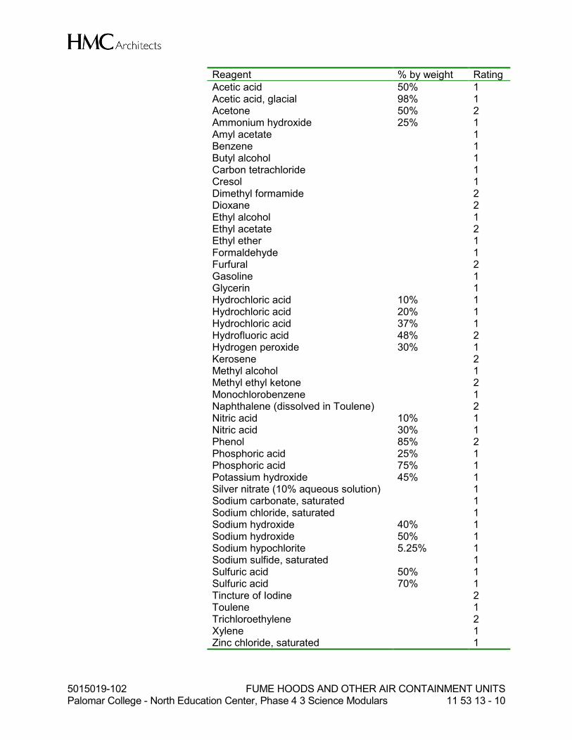
5015019-102 FUME HOODS AND OTHER AIR CONTAINMENT UNITS Palomar College - North Education Center, Phase 4 3 Science Modulars 11 53 13 - 10
Reagent % by weight Rating
Acetic acid 50% 1 Acetic acid, glacial 98% 1 Acetone 50% 2 Ammonium hydroxide 25% 1 Amyl acetate 1 Benzene 1 Butyl alcohol 1 Carbon tetrachloride 1 Cresol 1 Dimethyl formamide 2 Dioxane 2 Ethyl alcohol 1 Ethyl acetate 2 Ethyl ether 1 Formaldehyde 1 Furfural 2 Gasoline 1 Glycerin 1 Hydrochloric acid 10% 1 Hydrochloric acid 20% 1 Hydrochloric acid 37% 1 Hydrofluoric acid 48% 2 Hydrogen peroxide 30% 1 Kerosene 2 Methyl alcohol 1 Methyl ethyl ketone 2 Monochlorobenzene 1 Naphthalene (dissolved in Toulene) 2 Nitric acid 10% 1 Nitric acid 30% 1 Phenol 85% 2 Phosphoric acid 25% 1 Phosphoric acid 75% 1 Potassium hydroxide 45% 1 Silver nitrate (10% aqueous solution) 1 Sodium carbonate, saturated 1 Sodium chloride, saturated 1 Sodium hydroxide 40% 1 Sodium hydroxide 50% 1 Sodium hypochlorite 5.25% 1 Sodium sulfide, saturated 1 Sulfuric acid 50% 1 Sulfuric acid 70% 1 Tincture of Iodine 2 Toulene 1 Trichloroethylene 2 Xylene 1 Zinc chloride, saturated 1
5015019-102 FUME HOODS AND OTHER AIR CONTAINMENT UNITS Palomar College - North Education Center, Phase 4 3 Science Modulars 11 53 13 - 11
Note: Maximum concentration is to be understood unless a lower concentration is shown in the table.
a. Physical Tests: 1). Abrasion: Finish shall have high abrasion resistance with maximum
weight loss of 5.5 mg per 100 cycles as tested on a Taber Abrasion Tester No. E40101 with 1000 gm wheel pressure and Calibrase No. CS10 wheel.
2). Hardness: Finish shall have surface hardness equivalent to 4H or 5H pencil lead.
3). Humidity: Finish shall withstand 1000 hours exposure in saturated atmosphere at 100°F (38°C).
4). Moisture: Finish shall withstand the following procedures with no visible effect: a). Boiling water flowing over 45 degree inclined surface for 5
minutes. b). 100 hours continuous contact with water-soaked cellulose
sponge, maintained in a wet condition throughout test. 5). Adhesion: Finish shall withstand the following test procedure with at
least 95 squares maintaining their finish. Using a razor blade, score the finish surface of the test panel through to the substrate with a pattern of 100 squares, each 1/16 inch x 1/16 inch. Brush away loose particles with a soft brush.
6). Salt spray: Finish shall withstand 200 hours exposure to salt spray test.
G. Fume Hood Liner Test: Polyresin 1. Test No. 1: Spills and Splashes:
a. Suspend a 42 inches (1067 mm) x 12 inches (305 mm) panel (42 inch (1067 mm) dimension horizontal) in a position to expose the surface to be tested in a vertical plane. Divide the panel vertically into 3/4 inch (19 mm) spaces.
b. Using an eyedropper, apply five drops of each reagent as listed. c. Liquid reagents shall be applied at the top of the panel and permitted to flow
down full panel height. (CAUTION! Flush away any reagent drops.) 2. Test No. 2: Fumes and Gases:
a. Prepare a panel 24 inches (610 mm) x 12 inches (305 mm) by dividing panel into 2 inch (51 mm) squares. Using 100 ml beakers, place 25 ml (approximately 1/2 inch (13 mm) of reagent) into each beaker. Place beakers in position so that test panel may be placed over beaker tops in the proper sequence. Place panel over beakers. Note: Beaker pouring lip permits atmospheric oxygen to enter and participate in the reaction of the reagent fumes.
b. After a 24 hour time period has elapsed, remove panel, flush off with water, clean with naphtha and detergent, rinse and wipe dry. Evaluate.
3. Evaluating Ratings:
0 No effect No detectable change in the material surface. 1 Excellent Slight detectable change in color or gloss but no change
in function or life of the surface. 2 Good A clearly discernable change in color or gloss but no
significant impairment of surface life or function.
5015019-102 FUME HOODS AND OTHER AIR CONTAINMENT UNITS Palomar College - North Education Center, Phase 4 3 Science Modulars 11 53 13 - 12
3 Fair Objectionable change in appearance due to discoloration or etch, possibly resulting in deterioration of function over an extended period of time.
4 Failure Pitting, cratering, or erosion of the surface. Obvious and significant deterioration.
4. Performance: Test results shall equal or exceed the following:
Reagent % by wt. Spills Fumes
Acetic acid, glacial 0 0 Acetone 0 0 Acid dichromate 1 1 Ammonium hydroxide 28% 0 0 Amyl acetate 0 0 Benzene 0 0 Butyl alcohol 0 0 Carbon tetrachloride 0 0 Chloroform 0 0 Chromic acid, saturated 3 0 Cresol 0 0 Dichloro acetic acid 93% 0 0 Dimethyl formamide 0 0 Dioxane 0 0 Ethyl acetate 0 0 Ethyl alcohol 0 0 Ethyl ether 0 0 Formaldehyde 37% 0 0 Formic Acid 88% 0 0 Furfural 2 0 Gasoline 0 0 Hydrochloric acid 48% 1 1 Hydrofluoric acid 37% 0 0 Hydrogen peroxide 30% 0 0 Methyl alcohol 0 0 Methyl ethyl ketone 0 0 Methylene chloride 0 0 Monochlorobenzene 0 0 Naphthalene 0 0 Nitric acid 20% 0 0 Nitric acid 30% 0 0 Nitric acid 70% 0 0 Phenol 85% 0 1 Phosphoric acid 85% 1 0 Silver Nitrate 10% 1 0 Sodium Hydroxide 10% 1 0 Sodium Hydroxide 20% 1 0 Sodium Hydroxide 40% 1 0 Sodium Hydroxide Flake 0 0 Sodium Sulfide, saturated 2 1 Sulfuric acid 33% 1 0 Sulfuric acid 77% 1 0 Sulfuric acid 93% 1 0
5015019-102 FUME HOODS AND OTHER AIR CONTAINMENT UNITS Palomar College - North Education Center, Phase 4 3 Science Modulars 11 53 13 - 13
Reagent % by wt. Spills Fumes Sulfuric acid/Nitric acid, equal parts 77%/70% 0 1 Tincture of Iodine 0 2 Trichloroethylene 0 0 Toluene 0 0 Xylene 0 0 Zinc Chloride 0 0
Note: Maximum concentration is to be understood unless a lower concentration is shown in the table.
2.03 DOWN DRAFT EXHAUST UNITS
A. Benchtop Units: 1. Custom fabricate low profile units with stainless steel exhaust grilles. Refer to
Laboratory Furnishings Drawings for size, location and details.
B. Materials: 1. Epoxy resin: As specified under section 11 53 10. 2. Stainless steel: As specified under section 11 53 10.
C. Ductwork 1. Ductwork shall be as specified under Division 23. 2. Downdraft box shall be tightly connected to the exhaust ducting underneath the
bench and shall not be removable.
D. Provide grilles as detailed on the Laboratory Furnishing drawings. Grilles shall be Type 316L stainless steel.
E. Final connection to the fume exhaust duct system under Division 23. Refer to the Equipment Exhaust Schedule for airflow rates.
PART 3 - EXECUTION
3.01 SITE CONDITIONS
A. Prior to installation of the Work of this Section, carefully inspect the installed Work specified in other sections and verify that all such Work is complete to the point where this installation may properly commence.
B. Verify that all Work has been installed in complete accordance with the original design, received submittals, and the manufacturer's recommendations.
C. In the event of discrepancy, immediately notify the Architect. Do not proceed with installation in areas of discrepancy until all such discrepancies have been fully resolved.
3.02 INSTALLATION
A. Work in this Section requires close coordination with Work specified in Division 22, Division 23 and Division 26, as well as installation by Owner of Owner furnished components. Coordinate all Work to ensure an orderly process in the Project, without
5015019-102 FUME HOODS AND OTHER AIR CONTAINMENT UNITS Palomar College - North Education Center, Phase 4 3 Science Modulars 11 53 13 - 14
removal of previously installed Work, and so as to prevent damage to finishes and products.
B. Coordinate location and alignment of fume hoods and cabinets for proper connection of all piping and duct work.
C. Install all equipment in accordance with applicable codes and regulations, accepted Shop Drawings, and as necessary for a complete operating system.
3.03 FIELD TESTING
A. Chemical Fume Hoods: 1. Fume hood field tests shall be performed by a qualified independent testing
company on each hood. 2. All laboratory supply, general exhaust, and fume exhaust HVAC systems shall be
operational during testing. 3. Test and certify each fume hood in accordance with ASHRAE Standard 110-2016
for Section 6.1 Flow Visualization, Section 6.2 Face Velocity Measurements, Section 6.3 Test Method for VAV Fume Hoods, Section 6.4 VAV Response Test, and Section 7 Tracer Gas Test Procedure testing requirements.
4. Flow Visualization: Fume hood shall provide complete containment of the smoke generated within the hood.
5. Face Velocity Measurements: Fume hoods shall be tested at the design operating condition sash opening height indicated in the Chemical Fume Hood Schedule. a. Fume hoods shall achieve the scheduled design operating condition average
face velocity within ±5 fpm. b. Individual face velocity readings shall not vary by more than 20% of the mean
between measurement grid locations. 6. Test Method for VAV Fume Hoods (Not Applicable to CAV Hoods): Perform this
test to confirm VAV controls are properly calibrated. Average and individual face velocity reading should meet the performance criteria indicated for Section 6.2 Face Velocity Measurements above.
7. VAV Response Test (Not Applicable to CAV Hoods): Perform this test to verify VAV controls are responding accurately to the opening of the fume hood sash. The time it takes from the start of the sash movement until the face velocity stabilizes shall be less than 5 seconds.
8. Tracer Gas Test Procedure: Fume hoods shall achieve an As-Installed (AI) performance rating equal or better than 0.10 ppm with 4.0 Lpm tracer gas release rate.
9. Cross Drafts: Fume hood testing shall also include measuring and documenting the vertical and horizontal cross-drafts at the face of the hood. Cross-drafts shall not exceed half of the fume hood face velocity.
10. Balancing of the HVAC systems is in the scope of work of Division 23.
3.04 CLEANING AND PROTECTION
A. Repair or remove and replace defective work as approved by the Architect upon completion of installation.
B. Adjust all moving or operating part to function within their design parameters.
5015019-102 FUME HOODS AND OTHER AIR CONTAINMENT UNITS Palomar College - North Education Center, Phase 4 3 Science Modulars 11 53 13 - 15
C. Clean equipment, touch up as required.
D. Protect all units before, during, and after installation. Damaged materials due to improper protection shall be cause for rejection.
END OF SECTION
5015019-102 LABORATORY SERVICE FITTINGS AND FIXTURES Palomar College - North Education Center, Phase 4 3 Science Modulars 11 53 43 - 1
SECTION 11 53 43
LABORATORY SERVICE FITTINGS AND FIXTURES
PART 1 - GENERAL
1.01 SECTION INCLUDES
A. Laboratory service fittings, valves, and related components.
B. Laboratory emergency plumbing fixtures.
C. Laboratory sink units.
1.02 RELATED SECTIONS
A. Division 22: Plumbing
B. Division 23: Heating, Ventilated, and Air-Conditioning
C. Division 26: Electrical
1.03 REFERENCES
A. Conform to SEFA 2-2010 Recommended Practices for Installation and SEFA 7-2010 Recommended Practices for Laboratory Fixtures as published by the Scientific Equipment and Furniture Association.
1.04 DESCRIPTION
A. Work includes but is not necessarily limited to furnishing to the project site for installation by Division 22, all laboratory fixtures, fittings, and emergency plumbing fixtures described herein and shown on the Laboratory Furnishings Drawings.
1.05 SUBMITTALS
A. Refer to General Conditions and Division 1 “Submittal Procedures” for submittal requirements. In addition to these requirements, provide submittal requirements specified herein.
B. Submittal requirements: 1. Submittal shall be prepared individually for this specification section. Arrange
product data, drawings and information for submission in a complete set for this specification section.
2. Submittal shall contain complete data for all items of this specification section. Periodic or partial submittals of individual components within this specification section will be returned as incomplete and rejected.
3. Submittals shall be organized by specification sequence with section and paragraph number identified.

5015019-102 LABORATORY SERVICE FITTINGS AND FIXTURES Palomar College - North Education Center, Phase 4 3 Science Modulars 11 53 43 - 2
4. Equipment and components being proposed shall be clearly labeled with all options and accessories indicated and shall be for this specific project.
C. Materials List/Product Data: Submit complete materials list, including catalogue data, of all materials, equipment, and products for Work in this Section.
D. Shop Drawings: Submit complete shop fabrication and installation drawings, including plans, elevations, sections, details and schedules. Show relationship to adjoining materials and construction. Shop Drawings shall be in the form of reproducibles or photocopies, not to exceed 11inches x 17 inches (A3) in size. Blueline prints are not acceptable.
E. Approved Substitution/Approved Equal: In addition to the items required in Division 1, all substitution requests shall include item-by-item comparison of the proposed substitution to this project specification. A copy of the project specification shall be submitted, with each item and subsection of the project specification marked as “Comply” or “Not Comply.” In any cases where “Not Comply” is indicated, an explanation of the relative advantages of the proposed design shall be provided. 1. Substitution shall not affect dimensions shown on Drawings. 2. The Contractor shall pay for changes to the building design, including engineering
design, detailing, utility and service requirements, and construction costs caused by the requested substitution.
3. Substitutions shall have no adverse affect on other trades, the construction schedule, or specified warranty requirements.
4. Maintenance and service parts shall be locally available for the proposed substitution.
F. Samples: Submit two (2) samples of each type of specified finish and color specified.
G. Certifications: As a condition of acceptance, submit certification stating that equipment is complete and ready for intended function.
H. Operations/Maintenance Manuals: Accompanying certification, submit for Architect's review and Owner's use, complete operating and maintenance manuals that describe proper operating procedures, maintenance and replacement schedules, components parts list, and closest factory representative for components and service.
1.06 PRODUCT HANDLING
A. Protection: Use all means necessary to protect work of this section before, during and after installation including installed work and materials of other trades.
B. Replacement: Any damaged work shall be replaced, repaired and restored to original condition to the approval of the Architect at no additional cost or inconvenience to the Owner.
1.07 QUALIFICATIONS
A. Work in this section shall be performed by a company having a minimum of eight years documented experience, and an established organization and production facilities including all tools, equipment and special machinery necessary for specializing in the

5015019-102 LABORATORY SERVICE FITTINGS AND FIXTURES Palomar College - North Education Center, Phase 4 3 Science Modulars 11 53 43 - 3
fabrication and installation of the type of equipment required, with skilled personnel, factory trained workmen and an experienced engineering department. Each shall have the demonstrated knowledge, ability and the proven capability to produce the specified equipment of the required quality and the proven capacity to complete an installation of this size and type within the required time limits.
B. Work in this Section requires close coordination with Work in electrical and mechanical Sections. Coordinate all Work to assure an orderly progress in the Project, without removal of previously installed Work, and so as to prevent damage to finishes and products.
C. Review conditions of installation, procedures and coordination with related Work.
D. Carefully inspect the installed Work specified in other Sections and verify that all such Work is complete and ready for the installation of this Work to properly commence.
E. Verify that all Work may be installed in complete accordance with the original design, reviewed submittals and manufacturer's recommendations.
1.08 WARRANTY
A. All products will be warranted to be free from defects in materials and workmanship for a period of one year following substantial completion. The manufacturer/dealer/subcontractor shall repair or replace any products (or parts thereof) that are found to be defective. Replacement will include any parts, labor, shipping, and travel expenses involved. Warranty replacement work must be scheduled in coordination with the College’s academic schedule and may therefore require evening and/or weekend hours.
PART 2 - PRODUCTS
2.01 GENERAL
A. All service fittings and emergency plumbing fixtures shall be specifically designed for laboratory use.
B. Service fittings, emergency fixtures, sinks, etc. specified in this Section shall be furnished and delivered to point of use for installation as specified in Division 22.
C. All service fittings shall be factory pre-assembled including the assembly of valves to turrets, mounting shanks to turrets, etc., and individually factory tested.
D. All laboratory service fittings shall be the product of one service fitting manufacturer to assure ease of replacement and maintenance.
E. All service valves, fittings, turrets, flange and accessories shall be forged brass with a minimum copper content of 85%.
F. Provide fittings as shown in laboratory fitting details for all laboratory equipment at locations shown on the Laboratory Furnishings drawings. See Service Fitting Schedule.

5015019-102 LABORATORY SERVICE FITTINGS AND FIXTURES Palomar College - North Education Center, Phase 4 3 Science Modulars 11 53 43 - 4
G. Assembly components and operating parts such as valve stems, renewable units, packing nuts, outlet nozzles and straight serrated hose ends shall be made from solid brass stock.
H. Replaceable seats, needle cones, valve disc screws and other accessories shall be Monel or stainless steel alloys especially selected for use intended.
I. Fittings shall be factory tested and shall be supplied with nipples, lock nuts, shanks, etc.
J. Serrated tip fittings shall be threaded with the hose end being tapered.
K. Turrets shall be brass drop forging of design indicated in details shown elsewhere in the Section and shall be one or two-way, as required, with 3/8 inch (9.525 mm) IPS female inlet thread for connections. Units shall be furnished with brass shanks, brass locknuts, and washers.
L. Fittings located on the same plane shall have their handles project the same distance from the plane of reference to present a uniform related appearance, regardless of valve type construction.
M. Flanges shall be brass forging of approved design with 3/8 inch (9.525 mm) IPS female inlet and outlet.
N. All goosenecks shall provide full thread for attachment of aerator or serrated hose ends.
O. Hot water/cold water gooseneck mixers and wall-mounted cold water goosenecks shall swivel. Swivel point shall be above valve body or at valve level if wall mounted. Swing joints shall have heavy Teflon type packings; "0" rings will not be permitted. Cold water goosenecks at cup sinks shall be rigid.
P. All fittings shall have plastic colored service index buttons as specified in this Section.
Q. Where shown on drawings and/or in fixture schedule, provide approved vacuum breakers for all potable hot and cold water fittings including fittings at fume hoods. Vacuum breakers for fume hood water fittings mounted remotely at top of fume hood. Provide approved backflow preventers at hand held drench hoses. See details on Laboratory Furnishings drawings.
R. Fittings and fixtures designated to be accessible to persons with disabilities (ADA) with operable parts shall be operable with one hand and shall not require tight grasping, pinching, or twisting of the wrist. The force required to activate operable parts shall be 5 pounds (22.2 N), maximum.
2.02 LABORATORY SERVICE FITTINGS
A. Manufacturers: 1. Products, which comply with this specification section as judged and approved by
the Architect, may be provided by the following manufacturers. All products specified in this section shall be provided by a single manufacturer. a. Water Saver Faucet Co., 701 West Erie Street, Chicago, IL 60610 Tel: (312)
666-5500.

5015019-102 LABORATORY SERVICE FITTINGS AND FIXTURES Palomar College - North Education Center, Phase 4 3 Science Modulars 11 53 43 - 5
b. T&S Brass and Bronze Works, Inc., 2 Saddleback Cove, P. O. Box 1088, Travelers Rest, SC 29690 Tel: (800) 476-4103.
c. Broen, Inc., 2820 Commerce Blvd., Birmingham, AL 35210 Tel: (800) 446-7326.
d. Approved substitution.
B. Cylindrical Pattern: 1. All service fittings shall have WaterSaver Standard turret style (not ColorTech) as
the basis of design.
C. Handles: 1. Faucets designated to be accessible to persons with disabilities (ADA): provide 4
inch “wrist-blade” handles with color coded screw-on index (identification) discs. Wrist-blade handles to be installed in the vertical position (off).
2. Laboratory air and vacuum valves at workstations indicated to be accessible to persons with disabilities (ADA) and all laboratory gas valves: Provide ball valves fitted with lever-type handles and color coded screw-on index (identification) discs.
3. Other fittings shall be fitted with four arm handles and color coded screw-on index discs.
D. Finish: As described elsewhere in this section.
E. Water Valves: 1. Water valves shall include a renewable unit containing all the working parts which
are subject to wear, including stainless steel or monel seat, monel screw and heavy duty seat disk and Teflon packing.
2. Volume control at deck mounted water faucets: a. Compression unit with integral adjustable volume control to regulate size of
inlet port of valve. 3. Volume control at fume hood water outlets: Serrated hose end shall have a 0.5
GPM removable flow restrictor insert to allow a perfect flow out of the outlet and eliminate any splashing or wide pattern spray.
4. Goosenecks: Unit shall be capable of being readily converted from compression to self-closing, and vice versa, without disturbing faucet body and shall also be capable of being readily converted from water construction to needle valve or steam valve construction having outside packing gland without disturbing faucet body.
5. Unit shall be sealed in valve body with special composition gasket. Metal-to-metal or ground joint type of sealing is not acceptable.
6. Water fixtures shall be fully assembled and factory tested at 80 psi (0.55 MPa) water pressure.
F. Needle Valves: Fully assembled and factory tested at 225 psi (1.55 MPa) air pressure. Gas, air, vacuum and steam needle valve fittings shall have stainless steel replaceable floating cone that is precision ground and self-centering which shall seat against a stainless steel or monel renewable valve seat. Action of valve shall be slow compression for fine control under pressure up to 150 psi (1.03 MPa) and shall have subject-to-wear parts easily replaceable. Provide pressure regulators designed for use with the appropriate service at locations indicated on the Laboratory Furnishing drawings. Needle valves for natural (laboratory) gas service shall be certified for use with natural gas by the Canadian Standards Association under ANSI Z21.15-2009/CGA 9.1-2009.
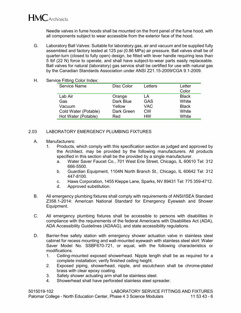
5015019-102 LABORATORY SERVICE FITTINGS AND FIXTURES Palomar College - North Education Center, Phase 4 3 Science Modulars 11 53 43 - 6
Needle valves in fume hoods shall be mounted on the front panel of the fume hood, with all components subject to wear accessible from the exterior face of the hood.
G. Laboratory Ball Valves: Suitable for laboratory gas, air and vacuum and be supplied fully assembled and factory tested at 125 psi (0.86 MPa) air pressure. Ball valves shall be of quarter-turn (closed to fully open) design, be fitted with lever handle requiring less than 5 lbf (22 N) force to operate, and shall have subject-to-wear parts easily replaceable. Ball valves for natural (laboratory) gas service shall be certified for use with natural gas by the Canadian Standards Association under ANSI Z21.15-2009/CGA 9.1-2009.
H. Service Fitting Color Index:
Service Name Disc Color Letters Letter Color
Lab Air Orange LA Black Gas Dark Blue GAS White Vacuum Yellow VAC Black Cold Water (Potable) Dark Green CW White Hot Water (Potable) Red HW White
2.03 LABORATORY EMERGENCY PLUMBING FIXTURES
A. Manufacturers: 1. Products, which comply with this specification section as judged and approved by
the Architect, may be provided by the following manufacturers. All products specified in this section shall be the provided by a single manufacturer. a. Water Saver Faucet Co., 701 West Erie Street, Chicago, IL 60610 Tel: 312
666-5500. b. Guardian Equipment, 1104N North Branch St., Chicago, IL 60642 Tel: 312
447-8100. c. Haws Corporation, 1455 Kleppe Lane, Sparks, NV 89431 Tel: 775 359-4712. d. Approved substitution.
B. All emergency plumbing fixtures shall comply with requirements of ANSI/ISEA Standard Z358.1-2014: American National Standard for Emergency Eyewash and Shower Equipment.
C. All emergency plumbing fixtures shall be accessible to persons with disabilities in compliance with the requirements of the federal Americans with Disabilities Act (ADA), ADA Accessibility Guidelines (ADAAG), and state accessibility regulations.
D. Barrier-free safety station with emergency shower actuation valve in stainless steel cabinet for recess mounting and wall-mounted eyewash with stainless steel skirt: Water Saver Model No. SSBF670-721, or equal, with the following characteristics or modifications. 1. Ceiling-mounted exposed showerhead. Nipple length shall be as required for a
complete installation; verify finished ceiling height. 2. Exposed piping, showerhead, nipple, and escutcheon shall be chrome-plated
brass with clear epoxy coating. 3. Safety shower actuating arm shall be stainless steel. 4. Showerhead shall have perforated stainless steel spreader.

5015019-102 LABORATORY SERVICE FITTINGS AND FIXTURES Palomar College - North Education Center, Phase 4 3 Science Modulars 11 53 43 - 7
5. Safety shower actuating arm shall be mounted in a flanged, recessed-mounted 18 gauge (1.3 mm) stainless steel cabinet with No. 4 finish.
6. Flag/paddle shall be epoxy-coated cast aluminum or stainless steel. 7. Eyewash heads shall be ABS plastic with float-off dust covers. 8. Stainless steel skirt shall have No. 4 finish. 9. Safety shower stay-open brass ball valve concealed behind stainless steel/access
panel housing. Eyewash stay open brass ball valve concealed behind skirt. 10. Fixture shall be furnished with green plastic sign with graphic symbol for safety
shower/eyewash.
E. Dual-purpose eye wash/drench hose, deck mounted: Water Saver Model No. EW1022-BP, or equal, with the following characteristics or modifications. 1. Dual-purpose eye wash/drench hose unit with dual gentle spray outlet heads and
squeeze handle/valve with locking clip. 2. Heads shall be equipped with flip top dust cover that automatically releases with
water pressure. 3. Flexible, reinforced PVC hose shall be furnished with swivel fitting at inlet end.
a. Under-counter hose guide bracket to prevent hose from tangling or binding. 4. Furnish with in-line backflow preventer at the hose inlet. 5. Mounting flange and squeeze valve shall be chrome-plated brass with clear epoxy
coating. 6. Mounting shank. 7. Fixture shall be furnished with green plastic sign with graphic symbol for eyewash.
F. Barrier-free eye wash, deck mounted, swing down “auto flow” style. Water Saver Model No. EWBF849.
1. Must be barrier free with supply arm angled downward so that spray heads are no more than 36 inches above finished floor in the down position.
2. Straight supply arm not meeting barrier free requirements is not acceptable and shall not be provided.
3. Coordinate configuration and location with other adjacent services. 4. Swing-down eye wash unit with dual gentle spray outlet heads and “AutoFlow”
feature. 5. Heads shall be equipped with flip top dust cover that automatically releases with
water pressure. 6. Furnish with inline backflow preventer at the inlet. 7. Strainer: Provide inline strainer to protect valve and spray heads. 8. Arm and elbow fitting shall be chrome-plated brass with clear epoxy coating. 9. Housing enclosure shall be stainless steel, Type 316. 10. Mounting shank. 11. Fixture shall be furnished with green plastic sign with graphic symbol for eyewash.
2.04 FINISHES
A. Service Fittings: 1. Polished chrome finish with clear, acid-resistant coating:
a. Chrome finish: All exposed surfaces shall be polished and buffed, then electroplated with one layer of nickel and one layer of chrome. Each layer of plating shall completely cover all visible areas. Total plating thickness shall be not less than 0.4 mil (10 µm).

5015019-102 LABORATORY SERVICE FITTINGS AND FIXTURES Palomar College - North Education Center, Phase 4 3 Science Modulars 11 53 43 - 8
b. Clear epoxy coating: Following plating, clear epoxy coating shall be applied to all exposed surfaces and then baked to permit curing. Surfaces shall have a minimum coating thickness of 2 mils (50 µm).
B. Service Fittings at Fume Hoods: 1. Preparation: Surfaces to be coated shall be polished or sandblasted to produce a
uniform fine-grained surface and immersed in a phosphoric acid cleaning solution to remove thoroughly all oil, grease and other foreign substances.
2. Epoxy finish: Following cleaning, coating material shall be electrostatically applied to all exposed surfaces. After application, coating shall be fully baked to permit curing. Coating material shall be free-flowing epoxy powder with particle size of 1.4 to 2.8 mils (35 to 70 µm). Surfaces shall have a minimum finished coating thickness of 2 mils (50 µm).
3. Color: a. Fittings inside fume hoods shall have a colored finish color-coded to match
the fitting service index color.
C. Performance requirements for coated finishes: 1. Chemical resistance:
a. Fume Test: Suspend coated samples in a container of at least 6 cu. foot (170 L) capacity, approximately 12 inches (300 mm) above open beakers, each containing 100 mL of 70% nitric acid, 94% sulfuric acid and 35% hydrochloric acid, respectively. After exposure to these fumes for 150 hours, the finish on the samples shall show no discoloration, disintegration or other effects.
b. Direct Application Test: Subject coated samples to the direct action of the following reagents and solvents at a temperature of 25°C dropping from a burette at the rate of 60 drops per minute for ten minutes. Finish on samples shall not rupture, though slight discoloration or temporary softening is permissible.
Reagent Concentration
Acetic Acid 98% Acetone Ammonium Hydroxide 28% Amyl Acetate Amyl Alcohol Benzene Butyl Alcohol Calcium Hypochlorite Carbon Disulfide Carbon Tetrachloride Chloroform Chromic Trioxide Acid Cresol Crude Oil Dioxane Distilled Water Ether Ethyl Acetate Ethyl Alcohol Ethyl Ether Formaldehyde 37%
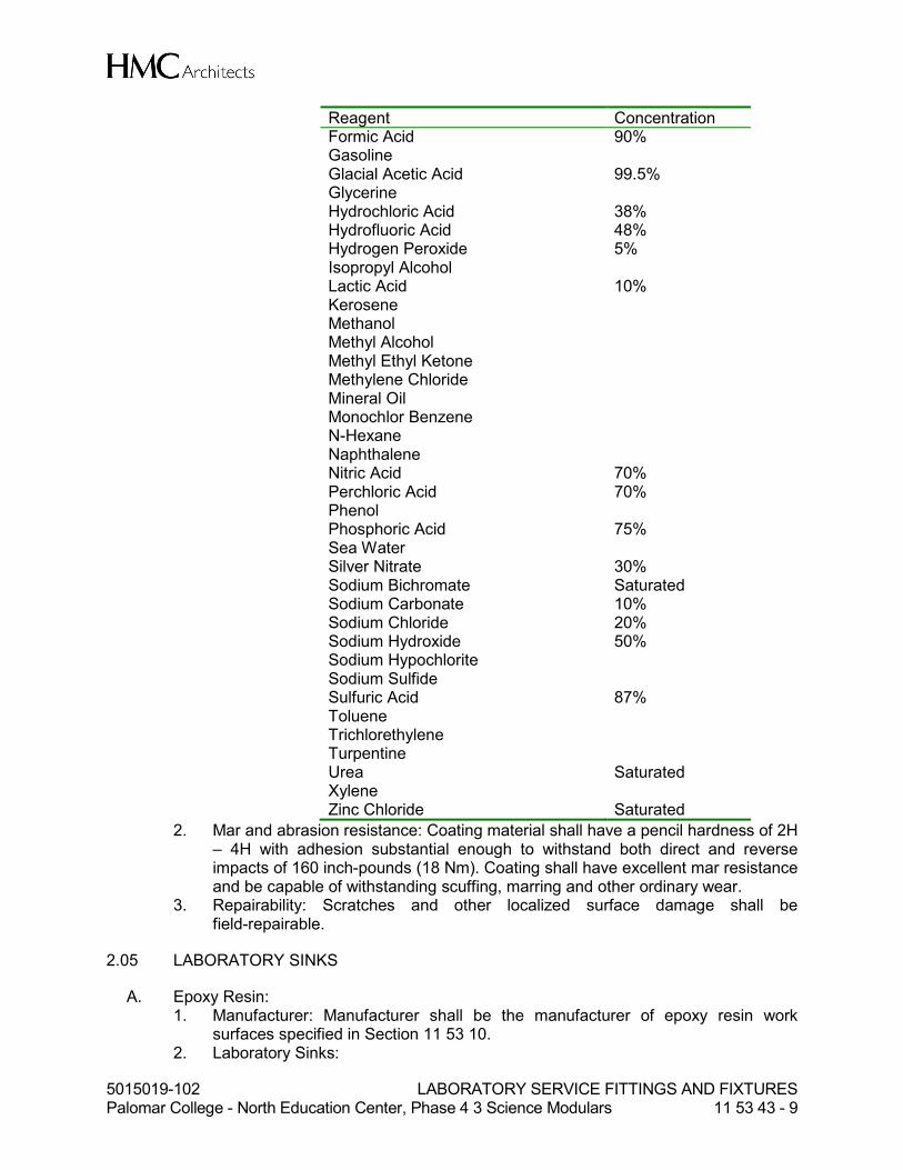
5015019-102 LABORATORY SERVICE FITTINGS AND FIXTURES Palomar College - North Education Center, Phase 4 3 Science Modulars 11 53 43 - 9
Reagent Concentration Formic Acid 90% Gasoline Glacial Acetic Acid 99.5% Glycerine Hydrochloric Acid 38% Hydrofluoric Acid 48% Hydrogen Peroxide 5% Isopropyl Alcohol Lactic Acid 10% Kerosene Methanol Methyl Alcohol Methyl Ethyl Ketone Methylene Chloride Mineral Oil Monochlor Benzene N-Hexane Naphthalene Nitric Acid 70% Perchloric Acid 70% Phenol Phosphoric Acid 75% Sea Water Silver Nitrate 30% Sodium Bichromate Saturated Sodium Carbonate 10% Sodium Chloride 20% Sodium Hydroxide 50% Sodium Hypochlorite Sodium Sulfide Sulfuric Acid 87% Toluene Trichlorethylene Turpentine Urea Saturated Xylene Zinc Chloride Saturated
2. Mar and abrasion resistance: Coating material shall have a pencil hardness of 2H – 4H with adhesion substantial enough to withstand both direct and reverse impacts of 160 inch-pounds (18 Nm). Coating shall have excellent mar resistance and be capable of withstanding scuffing, marring and other ordinary wear.
3. Repairability: Scratches and other localized surface damage shall be field-repairable.
2.05 LABORATORY SINKS
A. Epoxy Resin: 1. Manufacturer: Manufacturer shall be the manufacturer of epoxy resin work
surfaces specified in Section 11 53 10. 2. Laboratory Sinks:

5015019-102 LABORATORY SERVICE FITTINGS AND FIXTURES Palomar College - North Education Center, Phase 4 3 Science Modulars 11 53 43 - 10
a. Drop-in Type: Drop-in installation by Division 11 in epoxy resin work surface, sizes as indicated on drawings. Color to match work surface.
b. Comply with the requirements of Section 11 53 10 for epoxy resin. c. All exposed edges shall be radiused not less than 1/4 inch (6 mm). d. Sink shall be set 1/8 inch (3 mm) below the level of the adjacent surface. e. Provide epoxy resin sink outlet in color to match sink with strainer, stopper
and open-end overflow, and install in sink with continuous bead of silicone sealant. 1). At black epoxy resin sinks, outlet shall be black polypropylene.
f. Provide tailpiece compatible with waste piping system for all sinks unless otherwise specified. Refer to Division 22 for piping requirements.
B. Epoxy resin, Polyolefin or Polypropylene Cup Sinks: 1. Fume Hood Locations: Provide cup sinks at fume hoods as described in Section
11 53 13. 2. Provide strainer for all cup sinks.
PART 3 - EXECUTION
3.01 SITE CONDITIONS
A. Inspection: 1. Prior to installation of fittings specified in Section 11 53 43, carefully inspect the
installed Work specified in other Sections and verify that all such Work is complete to the point where this installation may properly commence.
2. Verify that all Work has been installed in complete accordance with the original design, approved submittals, and the manufacturer's recommendations.
B. Discrepancy: 1. In the event of discrepancy, immediately notify the Architect.
3.02 PACKING AND DELIVERY
A. Deliver all fittings and fixtures to job site in recommended packaging, with each fitting individually packaged, marked, and scheduled for point of use.
B. Inventory fittings, at job site, verify that type and quantity are correct, and re-package until installed.
C. Store in clean, dry location.
3.03 INSTALLATION
A. Set internal volume control on all cup sink water fittings so water does not splash out of sink.
END OF SECTION
5015019-102.pvc GENERAL PLUMBING REQUIREMENTS Palomar College – North Education Center, Phase 4 3 Science Modulars 22 00 00 - 1
SECTION 22 00 00
GENERAL PLUMBING REQUIREMENTS
PART 1 - GENERAL
1.01 RELATED DOCUMENTS
A. Drawings and general provisions of the Contract, including General and Supplementary Conditions and Division 01 Specification Sections, apply to this Section.
1.02 SCOPE
A. Basic plumbing requirements specifically applicable to Division 22 Sections.
B. Work includes but is not necessarily limited to the following: 1. Labor, materials, services, equipment, and appliances required for completion of
tasks as indicated on drawing or in specification or as inherently necessary to prepare spaces and systems for new installations as follows: a. Heating, ventilating and air conditioning systems and equipment b. Plumbing systems and equipment
1.03 DRAWINGS AND SPECIFICATIONS
A. Drawings accompanying these Specifications show intent of Work to be done. Specifications shall identify quality and grade of installation and where equipment and hardware is not particularly specified, Contractor shall provide submittals for all products and install them per manufacturers’ recommendations, and in a first class manner.
B. Examine Drawings and Specifications for elements in connection with this Work; determine existing and new general construction conditions and be familiar with all limitations caused by such conditions.
C. Plans are intended to show general arrangement and extent of Work contemplated. Exact location and arrangement of parts shall be determined after the College has reviewed equipment, as Work progresses, to conform in best possible manner with surroundings, and as directed by the College’s Representative.
D. Contract Documents are in part diagrammatic and intended to show the scope and general arrangement of the Work under this Contract. The Contractor shall follow these drawings in laying out the equipment, piping and ductwork. Drawings are not intended to be scaled for roughing in measurements or to serve as shop drawings. Where job conditions require minor changes or adjustments in the indicated locations or arrangement of the Work, such changes shall be made without change in the Contract amount.
E. Follow dimensions without regard to scale. Where no figures or notations are given,

5015019-102.pvc GENERAL PLUMBING REQUIREMENTS Palomar College – North Education Center, Phase 4 3 Science Modulars 22 00 00 - 2
the Plans shall be followed.
1.04 UTILITIES
A. Location and sizes of electrical, mechanical and plumbing service facilities are shown in accordance with data secured from existing record drawings and site observations. Data shown are offered as an estimating guide without guarantee of accuracy. Check and verify all data given, and verify exact location of all utility services pertaining to Work prior to excavation or performing Work.
1.05 APPLICABLE REFERENCE STANDARDS, CODES AND REGULATIONS:
A. Meet requirements of all state codes having jurisdiction.
B. State of California Code of Regulations: 1. Title 8, Industrial Relations 2. Title 19, State Fire Marshal Regulations 3. Current California Building Code (CBC), Title 24, Part 2 4. Current California Electrical Code, Title 24, Part 3 5. Current California Mechanical Code, Title 24, Part 4 6. Current California Plumbing Code, Title 24, Part 5 7. Current California Fire Code, Title 24, Part 9 8. Current California Standards Code, Title 24, Part 12 9. Title 24, Energy Conservation Standards
C. Additional Referenced Standards: 1. AABC Associated Air Balance Council 2. AMCA Air Moving and Conditioning Association 3. ARI Air-Conditioning and Refrigeration Institute 4. ASHRAE American Society of Heating, Refrigeration and Air Conditioning
Engineers 5. ASME American Society of Mechanical Engineers 6. ASTM American Society for Testing and Materials 7. NEMA National Electrical Manufacturer’s Association 8. NFPA National Fire Protection Association Standards 9. PDI Plumbing and Drainage Institute 10. UL Underwriters Laboratories
D. Codes and ordinances having jurisdiction over Work are minimum requirements; but, if Contract Documents indicate requirements, which are in excess of those minimum requirements, then requirements of the Contract Documents shall be followed. Should there be any conflicts between Contract Documents or codes or any ordinances having jurisdiction, report these to the College’s Representative.
E. Obtain permits, and request inspections from authority having jurisdiction.
1.06 PROJECT AND SITE CONDITIONS
A. The arrangement of and connection to equipment shown on the drawings is based upon information available and is not intended to show exact dimensions peculiar to a
5015019-102.pvc GENERAL PLUMBING REQUIREMENTS Palomar College – North Education Center, Phase 4 3 Science Modulars 22 00 00 - 3
specific manufacturer. The Drawings are, in part, diagrammatic and some features of the illustrated equipment installations may require revision to meet actual equipment installation requirements. Structural supports, housekeeping pads, piping connections and adjacent equipment may have to be altered to accommodate the equipment provided. No additional payment will be made for such revisions or alterations.
B. Examine all Drawings and Specifications to be fully cognizant of all work required under this Division.
C. Examine site related work and surfaces before starting work of any Section.
D. Install Work in locations shown on approved Drawings, unless prevented by Project conditions.
E. Prepare revised shop drawings showing proposed rearrangement of Work to meet Project conditions, including changes to Work specified in other Sections. Obtain permission from the College’s Representative before proceeding.
F. Beginning work of any Section constitutes acceptance of conditions.
1.07 COOPERATION WITH WORK UNDER OTHER DIVISIONS
A. Cooperate with other trades to facilitate general progress of Work. Allow all other trades every reasonable opportunity for installation of their work.
B. Work under this Division shall follow general building construction closely. Set pipe sleeves and inserts and verify that openings for chases and pipes are provided.
C. Work with other trades in determining exact location of outlets, pipes, and pieces of equipment to avoid interference with lines required to maintain proper installation of Work.
D. Make such progress in the Work to not delay work of other trades.
E. Mechanical Work shall have precedence over the other in the following sequence: 1. Soil and waste piping 2. Hydronic piping 3. Ductwork 4. Fire sprinkler piping 5. Domestic water piping
1.08 DISCREPANCIES
A. The Contractor shall check all Drawings furnished him immediately upon their receipt and shall promptly notify the College’s Representative of any discrepancies. Figures marked on Drawings shall in general be followed in preference to scale measurements. Piping and instrumentation diagrams shall in general govern floor plans and sections. Large-scale drawings shall in general govern small-scale drawings.
5015019-102.pvc GENERAL PLUMBING REQUIREMENTS Palomar College – North Education Center, Phase 4 3 Science Modulars 22 00 00 - 4
B. Where requirements between Drawings and Specifications conflict, the more restrictive provisions shall apply.
C. If any part of the Specifications or Drawings appears unclear or contradictory, apply to College’s Representative for interpretation and decision as early as possible, including during bidding period. Do not proceed with such work without College Representatives decision. Beginning work of any Section constitutes acceptance of conditions.
1.09 CHANGES
A. The Contractor shall be responsible to make and obtain approval from the College’s Representative for all necessary adjustments in piping and equipment layouts as required to accommodate the relocations of equipment and/or devices, which are affected by any approved authorized changes or Product substitutions. All changes shall be clearly indicated on the "Record" drawings.
1.10 SUBMITTALS
A. Refer to Division 01 for additional requirements.
B. The manufacturer, contractor or supplier shall include a written statement that the submitted equipment, hardware or accessory complies with the requirement of that particular specification section. 1. THE MANUFACTURER SHALL RESUBMIT THE SPECIFICATION SECTION
SHOWING COMPLIANCE WITH EACH RESPECTIVE PARAGRAPHS AND SPECIFIED ITEMS AND FEATURES IN THAT PARTICULAR SPECIFICATION SECTION.
2. ALL EXCEPTIONS SHALL BE CLEARLY IDENTIFIED BY REFERENCING RESPECTIVE PARAGRAPH AND OTHER REQUIREMENTS ALONG WITH PROPOSED ALTERNATIVE.
3. INDIVIDUAL OR PARTIAL SUBMITTALS ARE NOT ACCEPTABLE AND WILL BE RETURNED WITHOUT REVIEW.
C. Submit all Division 22 shop drawings and product data grouped and referenced by the specification technical section numbers in one complete submittal package. 1. INDIVIDUAL OR PARTIAL SUBMITTALS ARE NOT ACCEPTABLE AND WILL
BE RETURNED WITHOUT REVIEW.
D. Note that prior to acceptance of shop drawings for review, a submittal schedule shall be submitted to the College’s Representative.
E. Shop Drawings: 1. Provide all shop drawings in latest version of Revit format. 2. Drawings shall be a minimum of 30 inches by 42 inches in size with a minimum
scale of 1/4-inch per foot, except as specified otherwise. 3. Include installation details of equipment indicating proposed location, layout and
arrangement, accessories, piping, and other items that must be shown to assure a coordinated installation.
4. Indicate adequate clearance for operation, maintenance, and replacement of

5015019-102.pvc GENERAL PLUMBING REQUIREMENTS Palomar College – North Education Center, Phase 4 3 Science Modulars 22 00 00 - 5
operating equipment devices. 5. If equipment is disapproved, revise drawings to show acceptable equipment and
resubmit.
F. Whenever more than one (1) manufacturer’s product is specified, the first named product is the basis of design used in the Work and the use of alternate-named manufacturer’s products or substitutes may require modifications in that design.
G. Proposed Products List: Include Products as required by the individual section in this Division.
H. The Contractor shall be responsible for all equipment ordered and/or installed prior to receipt of shop drawings returned from the College’s Representative bearing the College's Representative stamp of "Reviewed". All corrections or modifications to the equipment as noted on the shop drawings shall be performed and equipment removed from the job site at the request of the College’s Representative without additional compensation.
I. Manufacturer's Data: For each manufactured item, provide current manufacturer's descriptive literature of cataloged products, certified equipment drawings, diagrams, performance and characteristic curves if applicable, and catalog cuts.
J. Standard Compliance: When materials or equipment provided by the Contractor must conform to the standards of organizations such as American National Standards Institute (ANSI) or American Water Works Association (AWWA), submit proof of such conformance to the College Representative for approval. If an organization uses a label or listing to indicate compliance with a particular standard, the label or listing will be acceptable evidence, unless otherwise specified. In lieu of the label or listing, submit a certificate from an independent testing organization, which is competent to perform acceptance testing and is approved by the College Representative. The certificate shall state that the item has been tested in accordance with the specified organization's test methods and that the item conforms to the specified organization's standard.
K. Certified Test Reports: Before delivery of materials and equipment, certified copies of all test reports specified in individual sections shall be submitted for approval.
L. Certificates of Compliance or Conformance: Submit manufacturer's certifications as required on products, materials, finish, and equipment indicated in the technical sections. Certifications shall be documents prepared specifically for this Contract. Pre-printed certifications and copies of previously submitted documents will not be acceptable. The manufacturer's certifications shall name the appropriate products, equipment, or materials and the publication specified as controlling the quality of that item. Certification shall not contain statements to imply that the item does not meet requirements specified, such as "as good as"; or "achieve the same end use and results as materials formulated in accordance with the referenced publications"; or "equal or exceed the service and performance of the specified material." Certifications shall simply state that the item conforms to the requirements specified. Certificates shall be printed on the manufacturer's letterhead and shall be signed by the manufacturer's official authorized to sign certificates of compliance or conformance.

5015019-102.pvc GENERAL PLUMBING REQUIREMENTS Palomar College – North Education Center, Phase 4 3 Science Modulars 22 00 00 - 6
1.11 PRODUCT ALTERNATIVES OR SUBSTITUTIONS
A. Refer to Division 01 for additional requirements.
1.12 GUARANTEE
A. Except as may be specified under other sections in the Specifications, guarantee all equipment furnished under the Specifications for a period of one year from date of project acceptance against defective workmanship and material and improper installation. Upon notification of failure, correct deficiency immediately and without cost to the College.
B. Standard warranty of manufacturer shall apply for replacement of parts after expiration of the above period. Manufacturer shall furnish replacement parts to the College for their service agency as directed.
1.13 OPERATION AND MAINTENANCE MANUAL
A. Refer to Division 01 for additional requirements.
1.14 POSTED OPERATING INSTRUCTIONS
A. Furnish approved operating instructions for systems and equipment indicated in the technical sections for use by operation and maintenance personnel.
B. The operating instructions shall include control diagrams, and control sequence for each principal system and equipment. Print or engrave operating instructions and frame under glass or in approved laminated plastic. Post instructions as directed. Attach or post operating instructions adjacent to each principal system and equipment. Provide weather-resistant materials or weatherproof enclosures for operating instructions exposed to the weather. Operating instructions shall not fade when exposed to sunlight and shall be secured to prevent easy removal or peeling.
1.15 INSTRUCTION TO THE COLLEGE PERSONNEL
A. Refer to Division 1 for additional requirements.
B. Provide training as specified in individual sections.
C. Before final inspection, instruct the College's designated personnel in operation, adjustment, and maintenance of products, equipment, and systems, at agreed upon times. Furnish the services of competent instructors to give full instruction to the College personnel in the adjustment, operation, and maintenance of systems and equipment, including pertinent safety requirements. Each instructor shall be thoroughly familiar with all parts of the installation and shall be trained in operating theory as well as practical operation and maintenance work.
D. The amount of time required for instruction on each item of equipment and system is that specified in individual sections.

5015019-102.pvc GENERAL PLUMBING REQUIREMENTS Palomar College – North Education Center, Phase 4 3 Science Modulars 22 00 00 - 7
E. Utilize operation and maintenance manuals as basis for instruction. Review contents of manual with the College's personnel in detail to explain all aspects of operation and maintenance.
F. Contractor shall video tape all in service training and instruction sessions and provide DVD, properly indexed, for training additional and future maintenance personnel.
G. Prepare and insert additional data in operations and maintenance manuals when need for additional data becomes apparent during instruction.
H. Submit six copies of Manufacturer’s Instruction Certificates as specified in individual specification Sections.
1.16 MANUFACTURER'S RECOMMENDATIONS
A. Where installation procedures or any part thereof are required to be in accordance with manufacturer's recommendations, furnish printed copies of the recommendations prior to installation. Installation of the item shall not proceed until recommendations are received. Failure to furnish recommendations shall be cause for rejection of the equipment or material.
1.17 PROJECT RECORD DOCUMENTS
A. Refer to Division 1 for additional requirements.
B. Maintain on site, one set of the following record documents; record actual revisions to the Work: 1. Contract Drawings. 2. Specifications. 3. Addenda. 4. Change Orders and other Modifications to the Contract. 5. Reviewed shop drawings, product data, and samples.
C. Store Record Documents separate from documents used for construction. Record documents shall be available for review by the Construction Inspector and Engineer at all times.
D. Record information concurrent with construction progress.
E. Specifications: Legibly mark and record at each Product section description of actual Products installed, including the following: 1. Manufacturer's name and product model and number. 2. Product substitutions or alternates utilized. 3. Changes made by Addenda and Modifications.
F. Record Documents and Shop Drawings: Legibly mark each item to record actual construction including: 1. Field changes of dimension and detail. 2. Details not on original Contract Drawings. 3. Provide all record documents and shop drawings in electronic format.

5015019-102.pvc GENERAL PLUMBING REQUIREMENTS Palomar College – North Education Center, Phase 4 3 Science Modulars 22 00 00 - 8
G. All changes, deviations and information recorded on the “Project Record Drawings” set during Construction shall be redrafted onto the latest version of AutoCAD. 1. Contractor hand marked or drafted redlined “Project Record Drawings” will not be
accepted.
H. Submit completed shop drawings to the College prior to completion in AutoCAD format.
1.18 DELIVERY AND STORAGE
A. Refer to Division 1 for additional requirements.
B. Handle, store, and protect equipment and materials in accordance with the manufacturer's recommendations and with the requirements of NFPA 70B P, Appendix I, titled "Equipment Storage and Maintenance During Construction." Replace damaged or defective items with new items.
1.19 EXTRA MATERIALS
A. Refer to Division 1 for additional requirements.
B. Unless otherwise specified, spare parts, wherever required by detailed specification sections, shall be stored in accordance with the provisions of this paragraph. Spare parts shall be tagged by project equipment number and identified as to part number, equipment manufacturer, and subassembly component (if appropriate). Spare parts subject to deterioration such as ferrous metal items and electrical components shall be properly protected by lubricants or desiccants and encapsulated in hermetically sealed plastic wrapping. Spare parts with individual weights less than 50 pounds and dimensions less than 2 feet wide, or 18 inches high, or 3 feet in length shall be stored in a wooden box with a hinged wooden cover and locking hasp. Hinges shall be strap type. The box shall be painted and identified with stenciled lettering stating the name of the equipment, equipment numbers, and the words “spare parts.” A neatly type inventory of spare parts shall be taped to the underside of the cover.
1.20 COMMISSIONING
A. Management: 1. The Commissioning Agent (CA) is hired directly by the College. 2. The CA directs and coordinates the commissioning activities and the reports to
the College’s Representative. 3. All members work together to fulfill their contracted responsibilities and meet the
objectives of the Contract Documents. 4. All contractors shall include the cost of commissioning in the contract price. The
contractors should be prepared to provide commissioning assistance and follow through until all the commissioned systems have been signed off by the commissioning provider and the College Representative.
5. In each purchase order or subcontract written, include requirements for submittal data, commissioning documentation, O&M data and training.
B. Commissioning requires the participation of Division 22 Plumbing Contractor to work to
5015019-102.pvc GENERAL PLUMBING REQUIREMENTS Palomar College – North Education Center, Phase 4 3 Science Modulars 22 00 00 - 9
ensure that all systems are operating in a manner consistent with the Design Intent. 1. The general commissioning requirements and coordination are detailed in
Division 1, Section 019000 General Commissioning Requirements and Division 22.
2. This Division shall be familiar with all parts of Division 1 and Division 22 and the commissioning plan issued by the Commissioning Authority and shall execute all commissioning responsibilities assigned to them in the Contract Documents.
C. The plumbing contractor is responsible for assisting the commissioning agent throughout the entire commissioning process. The work is not complete until the commissioning agent and the College Representative has signed off on the commissioned systems.
1.21 COMMISSIONING RESPONSIBILITIES
A. Plumbing Contractor: The commissioning responsibilities applicable to the plumbing contractor are as follows (all references apply to commissioned equipment only): 1. All contractors shall include the cost of commissioning in the contract price. The
contractors should be prepared to provide commissioning assistance and follow through until all the commissioned systems have been signed off by the commissioning provider and the College Representative.
2. In each purchase order or subcontract written, include requirements for submittal data, commissioning documentation, O&M data and training.
3. General Contractor shall attend a commissioning kickoff meeting and other meetings necessary to facilitate the commissioning process.
4. General Contractor shall provide the Commissioning Provider with normal cut sheets and shop drawing submittals of commissioned equipment.
5. General Contractor shall provide additional requested documentation, prior to normal O&M manual submittals, to the Commissioning Provider for development of start-up and functional testing procedures. a. Typically this will include detailed manufacturer installation and start-up,
operating, troubleshooting and maintenance procedures.In addition, the installation, start-up and checkout materials that are actually shipped inside the equipment and the actual field checkout sheet forms to be used by the factory or field technicians shall be submitted to the Commissioning Provider.
b. The Commissioning Provider may request further documentation necessary for the commissioning process.
6. General Contractor shall provide a copy of the O&M manuals and submittals of commissioned equipment, through normal channels, to the Commissioning Provider for review.
7. Sub-Contractors and design engineers shall assist in clarifying the operation and control of commissioned equipment in areas where the specifications, control drawings or equipment documentation is not sufficient for writing detailed testing procedures.
8. General Contractor shall provide limited assistance to the Commissioning Provider in preparing the specific functional performance test procedures. Sub-Contractors shall review test procedures to ensure feasibility, safety and equipment protection and provide necessary written alarm limits to be used during the tests.
5015019-102.pvc GENERAL PLUMBING REQUIREMENTS Palomar College – North Education Center, Phase 4 3 Science Modulars 22 00 00 - 10
9. General Contractor shall develop a full start-up and initial checkout plan using manufacturer’s start-up procedures and the pre-functional checklists from the Commissioning Provider for all commissioned equipment. Submit to Commissioning Provider for review prior to startup.
10. During the startup and initial checkout process, execute the plumbing related portions of the pre-functional checklists for all commissioned equipment.
11. Perform and clearly document all completed startup and system operational checkout procedures, providing a copy to the Commissioning Provider.
12. Address current Engineer of Record punch list items before functional testing. 13. Provide skilled technicians to execute starting of equipment and to execute the
functional performance tests. Ensure that they are available and present during the agreed upon schedules and for sufficient duration to complete the necessary tests, adjustments and problem-solving.
14. Provide skilled technicians to perform functional performance testing under the direction of the Commissioning Provider. Assist the Commissioning Provider in interpreting the monitoring data, as necessary.
15. Correct deficiencies (differences between specified and observed performance) as interpreted by the Commissioning Provider, College's Representative and Engineer of Record and retest the equipment.
16. Prepare O&M manuals according to the Contract Documents, including clarifying and updating the original sequences of operation to as-built conditions.
17. During construction, maintain as-built red-line drawings for all drawings and final CAD as-builts for contractor-generated coordination drawings. Update after completion of commissioning.
18. Provide training of the College Representative’s operating staff using expert qualified personnel, as specified.
19. Coordinate with equipment manufacturers to determine specific requirements to maintain the validity of the warranty.
20. Execute any deferred functional performance testing, witnessed by the Commissioning Provider, according to the specifications.
21. Correct deficiencies and make necessary adjustments to O&M manuals and as-built drawings for applicable issues identified in any seasonal testing.
B. Plumbing Contractor. The responsibilities of the plumbing contractor, during construction and acceptance phases in addition to those listed in (A) are: 1. Provide startup for all plumbing equipment, except for the building automation
control system. 2. Assist and cooperate with the TAB contractor and Commissioning Provider by:
a. Putting all plumbing equipment and systems into operation and continuing the operation during each working day of TAB and commissioning, as required.
b. Providing temperature and pressure taps according to the Construction Documents for TAB and commissioning testing.
3. Prepare a preliminary schedule for pipe testing, flushing and cleaning, equipment start-up and completion for use by the Commissioning Provider. Update the schedule as appropriate.
4. Notify the College's Representative when pipe system testing, flushing, cleaning, startup of each piece of equipment. Be responsible to notify the College’s Representative or Commissioning Provider, ahead of time, when commissioning activities not yet performed or not yet scheduled will delay construction. Be
5015019-102.pvc GENERAL PLUMBING REQUIREMENTS Palomar College – North Education Center, Phase 4 3 Science Modulars 22 00 00 - 11
proactive in seeing that commissioning processes are executed and that the Commissioning Provider has the scheduling information needed to efficiently execute the commissioning process.
PART 2 - PRODUCTS (NOT APPLICABLE)
PART 3 - EXECUTION
3.01 GENERAL
A. Obtain and pay for all permits and inspections, including any independent testing required to verify standard compliance, and deliver certificates for same to the College’s Representative.
3.02 WORK RESPONSIBILITIES
A. The drawings indicate diagrammatically the desired locations or arrangement of piping, equipment, etc., and are to be followed as closely as possible. Proper judgment must be exercised in executing the work to secure the best possible installation in the available space and to overcome local difficulties due to space limitations or interference with structural conditions.
B. The Contractor is responsible for the correct placing of Work and the proper location and connection of Work in relation to the work of other trades. Advise appropriate trade as to locations of access panels.
C. In the event changes in the indicated locations or arrangements are necessary, due to developed conditions in the building construction or rearrangement of furnishings or equipment, such changes shall be made without extra cost, providing the change is ordered before the ductwork, piping, etc. and work directly connected to same is installed and no extra materials are required.
D. Where equipment is furnished by others, verify dimensions and the correct locations of this equipment before proceeding with the roughing-in of connections.
E. All scaled and figured dimensions are approximate of typical equipment of the class indicated. Before proceeding with any work, carefully check and verify all dimensions, sizes, etc. with the drawings to see that the equipment will fit into the spaces provided without violation of applicable codes.
F. Should any changes to the Work indicated on the Drawings or described in the Specifications be necessary in order to comply with the above requirements, notify the College immediately and cease work on all parts of the contract, which are affected until approval for any required modifications to the construction has been obtained from the College.
G. Be responsible for any cooperative work, which must be altered due to lack of proper supervision or failure to make proper provisions in time. Such changes shall be under
5015019-102.pvc GENERAL PLUMBING REQUIREMENTS Palomar College – North Education Center, Phase 4 3 Science Modulars 22 00 00 - 12
direction of the College and shall be made to his satisfaction. Perform all Work with competent and skilled personnel.
H. All work, including aesthetic as well as mechanical aspects of the Work, shall be of the highest quality consistent with the best practices of the trade.
I. Replace or repair, without additional compensation, any work, which, in the opinion of the College, does not comply with these requirements.
3.03 PAINTING
A. Refer to Division 09 9000 Painting for additional requirements.
B. Factory Applied: 1. Plumbing equipment shall have factory-applied painting systems which shall, as
a minimum, meet the requirements of NEMA ICS 6 corrosion-resistance test, except equipment specified to meet requirements of ANSI C37.20 shall have a finish as specified in ANSI C37.20.
2. Refer to individual sections of this Division for more stringent requirements.
C. Field Applied: 1. Paint all plumbing equipment as required to touch up, to match finish on other
equipment in adjacent spaces or to meet safety criteria. 2. Paint all exposed plumbing piping, valves, supports, hangers and appurtenances.
Provide minimum 5 mils dry film thickness. 3. Paint shall be a high performance polyurethane enamel coating system. 4. Acceptable primer manufacturers include:
a. Ameron Amershield VOC, Tnemec's Series 1075 (1074) Endura-Shield, semi-gloss (gloss) sheen or equal.
5. Acceptable paint manufacturers include: a. Ameron, Tnemec or engineer approved equal.
3.04 COMMISSIONING TRAINING OF COLLEGE’S REPRESENTATIVE PERSONNEL
A. The General Contractor shall be responsible for training coordination and scheduling and ultimately to ensure that training is completed.
B. The Commissioning Provider shall be responsible for reviewing the content and adequacy of the training of College’s Representative personnel for commissioned equipment.
C. Plumbing Contractor. The plumbing contractor shall have the following training responsibilities: 1. Provide the Commissioning Provider and A/E with a training plan at least two
weeks before the planned training. 2. Provide designated College personnel with comprehensive orientation and
training in the understanding of the systems and the operation and maintenance of each piece of plumbing equipment.
3. Training shall normally start with classroom sessions followed by hands-on training on each piece of equipment, which shall illustrate the various modes of
5015019-102.pvc GENERAL PLUMBING REQUIREMENTS Palomar College – North Education Center, Phase 4 3 Science Modulars 22 00 00 - 13
operation, including startup, shutdown, power failure, etc. 4. During any demonstration, should the system fail to perform in accordance with
the requirements of the O&M manual or sequence of operations, the system will be repaired or adjusted as necessary and the demonstration repeated.
5. The appropriate trade or manufacturer's representative shall provide the instructions on each major piece of equipment. This person may be the start-up technician for the piece of equipment, the installing contractor or manufacturer’s representative. Practical building operating expertise as well as in-depth knowledge of all modes of operation of the specific piece of equipment are required. More than one party may be required to execute the training.
6. The controls contractor shall attend sessions other than the controls training, as requested, to discuss the interaction of the controls system as it relates to the equipment being discussed.
7. The training sessions shall follow the outline in the Table of Contents of the operation and maintenance manual and illustrate whenever possible the use of the O&M manuals for reference.
8. Training shall include: a. Use of the printed installation, operation and maintenance instruction
material included in the O&M manuals. b. A review of the written O&M instructions emphasizing safe and proper
operating requirements, preventative maintenance, special tools needed and spare parts inventory suggestions. The training shall include start-up, operation in all modes possible, shut-down, seasonal changeover and any emergency procedures.
c. Discussion of relevant health and safety issues and concerns. d. Discussion of warranties and guarantees. e. Common troubleshooting problems and solutions. f. Explanatory information included in the O&M manuals and the location of
all plans and manuals in the facility. g. Discussion of any peculiarities of equipment installation or operation. h. Classroom sessions shall include the use of overhead projections, slides,
video/audio-taped material as might be appropriate. 9. Hands-on training shall include start-up, operation in all modes possible,
including manual, shut-down and any emergency procedures and preventative maintenance for all pieces of equipment.
10. The plumbing contractor shall fully explain and demonstrate the operation, function and overrides of any local packaged controls, not controlled by the central control system.
11. Training shall occur after functional testing is complete, unless approved otherwise by the College’s Representative.
END OF SECTION
5015019-102.pvc COMMON WORK RESULTS FOR PLUMBING Palomar College – North Education Center, Phase 4 3 Science Modulars 22 05 00 - 1
SECTION 22 05 00
COMMON WORK RESULTS FOR PLUMBING
PART 1 - GENERAL
1.01 RELATED DOCUMENTS
A. Drawings and general provisions of the Contract, including General and Supplementary Conditions and Division 01 Specification Sections, apply to this Section.
1.02 SUMMARY
A. This Section includes the following:
1. Piping materials and installation instructions common to most piping systems. 2. Transition fittings. 3. Dielectric fittings. 4. Mechanical sleeve seals. 5. Sleeves. 6. Escutcheons. 7. Grout. 8. Equipment installation requirements common to equipment sections. 9. Painting and finishing. 10. Concrete bases. 11. Supports and anchorages.
1.03 DEFINITIONS
A. Finished Spaces: Spaces other than mechanical and electrical equipment rooms, furred spaces, pipe chases, unheated spaces immediately below roof, spaces above ceilings, unexcavated spaces, crawlspaces, and tunnels.
B. Exposed, Interior Installations: Exposed to view indoors. Examples include finished occupied spaces and mechanical equipment rooms.
C. Exposed, Exterior Installations: Exposed to view outdoors or subject to outdoor ambient temperatures and weather conditions. Examples include rooftop locations.
D. Concealed, Interior Installations: Concealed from view and protected from physical contact by building occupants. Examples include above ceilings and in chases.
E. Concealed, Exterior Installations: Concealed from view and protected from weather conditions and physical contact by building occupants but subject to outdoor ambient temperatures. Examples include installations within unheated shelters.
F. The following are industry abbreviations for plastic materials:
1. ABS: Acrylonitrile-butadiene-styrene plastic. 2. CPVC: Chlorinated polyvinyl chloride plastic. 3. PE: Polyethylene plastic. 4. PVC: Polyvinyl chloride plastic.

5015019-102.pvc COMMON WORK RESULTS FOR PLUMBING Palomar College – North Education Center, Phase 4 3 Science Modulars 22 05 00 - 2
G. The following are industry abbreviations for rubber materials:
1. EPDM: Ethylene-propylene-diene terpolymer rubber. 2. NBR: Acrylonitrile-butadiene rubber.
1.04 SUBMITTALS
A. THE MANUFACTURER, CONTRACTOR OR SUPPLIER SHALL INCLUDE A WRITTEN STATEMENT THAT THE SUBMITTED EQUIPMENT, HARDWARE OR ACCESSORY COMPLIES WITH THE REQUIREMENT OF THIS PARTICULAR SPECIFICATION SECTION.
1. THE MANUFACTURER SHALL RESUBMIT THIS SPECIFICATION SECTION SHOWING COMPLIANCE WITH EACH RESPECTIVE PARAGRAPHS AND SPECIFIED ITEMS AND FEATURES.
2. ALL EXCEPTIONS SHALL BE CLEARLY IDENTIFIED BY REFERENCING RESPECTIVE PARAGRAPH AND OTHER REQUIREMENTS ALONG WITH PROPOSED ALTERNATIVE.
3. INDIVIDUAL OR PARTIAL SUBMITTALS ARE NOT ACCEPTABLE AND WILL BE RETURNED WITHOUT REVIEW.
B. Product Data: For the following:
1. Transition fittings. 2. Dielectric fittings. 3. Mechanical sleeve seals. 4. Escutcheons.
C. Welding certificates.
1.05 QUALITY ASSURANCE
A. Steel Support Welding: Qualify processes and operators according to AWS D1.1, "Structural Welding Code--Steel."
B. Steel Pipe Welding: Qualify processes and operators according to ASME Boiler and Pressure Vessel Code: Section IX, "Welding and Brazing Qualifications."
1. Comply with provisions in ASME B31 Series, "Code for Pressure Piping." 2. Certify that each welder has passed AWS qualification tests for welding processes
involved and that certification is current.
C. Electrical Characteristics for Plumbing Equipment: Equipment of higher electrical characteristics may be furnished provided such proposed equipment is approved in writing and connecting electrical services, circuit breakers, and conduit sizes are appropriately modified. If minimum energy ratings or efficiencies are specified, equipment shall comply with requirements.
1.06 DELIVERY, STORAGE, AND HANDLING
A. Deliver pipes and tubes with factory-applied end caps. Maintain end caps through shipping, storage, and handling to prevent pipe end damage and to prevent entrance of dirt, debris, and moisture.
5015019-102.pvc COMMON WORK RESULTS FOR PLUMBING Palomar College – North Education Center, Phase 4 3 Science Modulars 22 05 00 - 3
B. Store plastic pipes protected from direct sunlight. Support to prevent sagging and bending.
1.07 COORDINATION
A. Arrange for pipe spaces, chases, slots, and openings in building structure during progress of construction, to allow for plumbing installations.
B. Coordinate installation of required supporting devices and set sleeves in poured-in-place concrete and other structural components as they are constructed.
C. Coordinate requirements for access panels and doors for plumbing items requiring access that are concealed behind finished surfaces. Access panels and doors are specified in Division 08 Section "Access Doors and Frames."
PART 2 - PRODUCTS
2.01 MANUFACTURERS
A. In other Part 2 articles where subparagraph titles below introduce lists, the following requirements apply for product selection:
1. Available Manufacturers: Subject to compliance with requirements, manufacturers offering products that may be incorporated into the Work include, but are not limited to, the manufacturers specified.
2. Manufacturers: Subject to compliance with requirements, provide products by the manufacturers specified.
2.02 PIPE, TUBE, AND FITTINGS
A. Refer to individual Division 22 piping Sections for pipe, tube, and fitting materials and joining methods.
B. Pipe Threads: ASME B1.20.1 for factory-threaded pipe and pipe fittings.
2.03 JOINING MATERIALS
A. Refer to individual Division 22 piping Sections for special joining materials not listed below.
B. Pipe-Flange Gasket Materials: Suitable for chemical and thermal conditions of piping system contents.
1. ASME B16.21, nonmetallic, flat, asbestos-free, 1/8-inch maximum thickness unless thickness or specific material is indicated.
a. Full-Face Type: For flat-face, Class 125, cast-iron and cast-bronze flanges. b. Narrow-Face Type: For raised-face, Class 250, cast-iron and steel flanges.
2. AWWA C110, rubber, flat face, 1/8 inch thick, unless otherwise indicated; and full-face or ring type, unless otherwise indicated.
C. Flange Bolts and Nuts: ASME B18.2.1, carbon steel, unless otherwise indicated.
5015019-102.pvc COMMON WORK RESULTS FOR PLUMBING Palomar College – North Education Center, Phase 4 3 Science Modulars 22 05 00 - 4
D. Plastic, Pipe-Flange Gasket, Bolts, and Nuts: Type and material recommended by piping system manufacturer, unless otherwise indicated.
E. Solder Filler Metals: ASTM B 32, lead-free alloys. Include water-flushable flux according to ASTM B 813.
F. Brazing Filler Metals: AWS A5.8, BCuP Series, copper-phosphorus alloys for general-duty brazing, unless otherwise indicated; and AWS A5.8, BAg1, silver alloy for refrigerant piping, unless otherwise indicated.
G. Welding Filler Metals: Comply with AWS D10.12 for welding materials appropriate for wall thickness and chemical analysis of steel pipe being welded.
H. Solvent Cements for Joining Plastic Piping:
1. ABS Piping: ASTM D 2235. 2. CPVC Piping: ASTM F 493. 3. PVC Piping: ASTM D 2564. Include primer according to ASTM F 656. 4. PVC to ABS Piping Transition: ASTM D 3138.
I. Fiberglass Pipe Adhesive: As furnished or recommended by pipe manufacturer.
2.04 TRANSITION FITTINGS
A. AWWA Transition Couplings: Same size as, and with pressure rating at least equal to and with ends compatible with, piping to be joined.
1. Available Manufacturers:
a. Dresser Industries, Inc.; DMD Div. b. Smith-Blair, Inc. c. Viking Johnson.
2. Underground Piping NPS 1-1/2 and Smaller: Manufactured fitting or coupling. 3. Underground Piping NPS 2 and Larger: AWWA C219, metal sleeve-type coupling. 4. Aboveground Pressure Piping: Pipe fitting.
B. Plastic-to-Metal Transition Fittings: CPVC and PVC one-piece fitting with manufacturer's Schedule 80 equivalent dimensions; one end with threaded brass insert, and one solvent-cement-joint end.
1. Available Manufacturers:
a. Eslon Thermoplastics.
C. Plastic-to-Metal Transition Adaptors: One-piece fitting with manufacturer's SDR 11 equivalent dimensions; one end with threaded brass insert, and one solvent-cement-joint end.
1. Available Manufacturers:
a. Thompson Plastics, Inc.
D. Plastic-to-Metal Transition Unions: MSS SP-107, CPVC and PVC four-part union. Include brass end, solvent-cement-joint end, rubber O-ring, and union nut.
1. Manufacturers:
a. Nibco, Inc.

5015019-102.pvc COMMON WORK RESULTS FOR PLUMBING Palomar College – North Education Center, Phase 4 3 Science Modulars 22 05 00 - 5
E. Flexible Transition Couplings for Underground Nonpressure Drainage Piping: ASTM C 1173 with elastomeric sleeve, ends same size as piping to be joined, and corrosion-resistant metal band on each end.
1. Manufacturers:
a. Cascade Waterworks Mfg. Co. b. Fernco, Inc. c. Mission Rubber Company. d. Plastic Oddities, Inc.
2.05 DIELECTRIC FITTINGS
A. Description: Combination fitting of copper alloy and ferrous materials with threaded, solder-joint, plain, or weld-neck end connections that match piping system materials.
B. Insulating Material: Suitable for system fluid, pressure, and temperature.
C. Dielectric Unions: Factory-fabricated, union assembly, for 250-psig minimum working pressure at 180 deg F.
1. Manufacturers:
a. Capitol Manufacturing Co. b. Central Plastics Company. c. Epco Sales, Inc. d. Watts Industries, Inc.; Water Products Div. e. Zurn Industries, Inc.; Wilkins Div.
D. Dielectric Flanges: Factory-fabricated, companion-flange assembly, for 150-psig minimum working pressure as required to suit system pressures.
1. Manufacturers:
a. Capitol Manufacturing Co. b. Central Plastics Company. c. Epco Sales, Inc. d. Watts Industries, Inc.; Water Products Div.
E. Dielectric-Flange Kits: Companion-flange assembly for field assembly. Include flanges, full-face- or ring-type neoprene or phenolic gasket, phenolic or polyethylene bolt sleeves, phenolic washers, and steel backing washers.
1. Manufacturers:
a. Advance Products & Systems, Inc. b. Calpico, Inc. c. Central Plastics Company. d. Pipeline Seal and Insulator, Inc.
2. Separate companion flanges and steel bolts and nuts shall have 150-psig minimum working pressure where required to suit system pressures.
F. Dielectric Couplings: Galvanized-steel coupling with inert and noncorrosive, thermoplastic lining; threaded ends; and 300-psig minimum working pressure at 225 deg F.
1. Manufacturers:
a. Calpico, Inc.

5015019-102.pvc COMMON WORK RESULTS FOR PLUMBING Palomar College – North Education Center, Phase 4 3 Science Modulars 22 05 00 - 6
b. Lochinvar Corp.
G. Dielectric Nipples: Electroplated steel nipple with inert and non-corrosive, thermoplastic lining; plain, threaded, or grooved ends; and 300-psig minimum working pressure at 225 deg F.
1. Manufacturers:
a. Perfection Corp. b. Precision Plumbing Products, Inc. c. Sioux Chief Manufacturing Co., Inc. d. Victaulic Co. of America.
2.06 MECHANICAL SLEEVE SEALS
A. Description: Modular sealing element unit, designed for field assembly, to fill annular space between pipe and sleeve.
1. Manufacturers:
a. Advance Products & Systems, Inc. b. Calpico, Inc. c. Metraflex Co. d. Pipeline Seal and Insulator, Inc.
2. Sealing Elements: EPDM interlocking links shaped to fit surface of pipe. Include type and number required for pipe material and size of pipe.
3. Pressure Plates: Stainless steel. Include two for each sealing element. 4. Connecting Bolts and Nuts: Stainless steel of length required to secure pressure
plates to sealing elements. Include one for each sealing element.
2.07 SLEEVES
A. Galvanized-Steel Sheet: 0.0239-inch minimum thickness; round tube closed with welded longitudinal joint.
B. Steel Pipe: ASTM A 53, Type E, Grade B, Schedule 40, galvanized, plain ends.
C. Cast Iron: Cast or fabricated "wall pipe" equivalent to ductile-iron pressure pipe, with plain ends and integral waterstop, unless otherwise indicated.
D. Stack Sleeve Fittings: Manufactured, cast-iron sleeve with integral clamping flange. Include clamping ring and bolts and nuts for membrane flashing.
1. Underdeck Clamp: Clamping ring with set screws.
E. Molded PVC: Permanent, with nailing flange for attaching to wooden forms.
F. PVC Pipe: ASTM D 1785, Schedule 40.
G. Molded PE: Reusable, PE, tapered-cup shaped, and smooth-outer surface with nailing flange for attaching to wooden forms.
2.08 ESCUTCHEONS
A. Description: Manufactured wall and ceiling escutcheons and floor plates, with an ID to
5015019-102.pvc COMMON WORK RESULTS FOR PLUMBING Palomar College – North Education Center, Phase 4 3 Science Modulars 22 05 00 - 7
closely fit around pipe, tube, and insulation of insulated piping and an OD that completely covers opening.
B. One-Piece, Deep-Pattern Type: Deep-drawn, box-shaped brass with polished chrome-plated finish.
C. One-Piece, Cast-Brass Type: With set screw.
1. Finish: Polished chrome-plated.
D. Split-Casting, Cast-Brass Type: With concealed hinge and set screw.
1. Finish: Polished chrome-plated.
E. One-Piece, Stamped-Steel Type: With set screw or spring clips and chrome-plated finish.
F. Split-Plate, Stamped-Steel Type: With concealed hinge, set screw or spring clips, and chrome-plated finish.
G. One-Piece, Floor-Plate Type: Cast-iron floor plate.
H. Split-Casting, Floor-Plate Type: Cast brass with concealed hinge and set screw.
2.09 GROUT
A. Description: ASTM C 1107, Grade B, non-shrink and nonmetallic, dry hydraulic-cement grout.
1. Characteristics: Post-hardening, volume-adjusting, non-staining, non-corrosive, nongaseous, and recommended for interior and exterior applications.
2. Design Mix: 5000-psi , 28-day compressive strength. 3. Packaging: Premixed and factory packaged.
PART 3 - EXECUTION
3.01 PIPING SYSTEMS - COMMON REQUIREMENTS
A. Install piping according to the following requirements and Division 22 Sections specifying piping systems.
B. Drawing plans, schematics, and diagrams indicate general location and arrangement of piping systems. Indicated locations and arrangements were used to size pipe and calculate friction loss, expansion, pump sizing, and other design considerations. Install piping as indicated unless deviations to layout are approved on Coordination Drawings.
C. Install piping in concealed locations, unless otherwise indicated and except in equipment rooms and service areas.
D. Install piping indicated to be exposed and piping in equipment rooms and service areas at right angles or parallel to building walls. Diagonal runs are prohibited unless specifically indicated otherwise.
E. Install piping above accessible ceilings to allow sufficient space for ceiling panel
5015019-102.pvc COMMON WORK RESULTS FOR PLUMBING Palomar College – North Education Center, Phase 4 3 Science Modulars 22 05 00 - 8
removal.
F. Install piping to permit valve servicing.
G. Install piping at indicated slopes.
H. Install piping free of sags and bends.
I. Install fittings for changes in direction and branch connections.
J. Install piping to allow application of insulation.
K. Select system components with pressure rating equal to or greater than system operating pressure.
L. Install escutcheons for penetrations of walls, ceilings, and floors according to the following:
1. New Piping:
a. Piping with Fitting or Sleeve Protruding from Wall: One-piece, deep-pattern type.
b. Chrome-Plated Piping: One-piece, cast-brass type with polished chrome-plated finish.
c. Insulated Piping: One-piece, stamped-steel type with spring clips. d. Bare Piping at Wall and Floor Penetrations in Finished Spaces: One-piece,
cast-brass type with polished chrome-plated finish. e. Bare Piping at Ceiling Penetrations in Finished Spaces: One-piece cast-
brass type with polished chrome-plated finish. f. Bare Piping in Unfinished Service Spaces: One-piece, cast-brass type with
polished chrome-plated finish. g. Bare Piping in Equipment Rooms: One-piece, cast-brass type. h. Bare Piping at Floor Penetrations in Equipment Rooms: One-piece, floor-
plate type.
M. Sleeves are not required for core-drilled holes.
N. Permanent sleeves are not required for holes formed by removable PE sleeves.
O. Install sleeves for pipes passing through concrete and masonry walls, gypsum-board partitions, and concrete floor and roof slabs.
1. Cut sleeves to length for mounting flush with both surfaces.
a. Exception: Extend sleeves installed in floors of mechanical equipment areas or other wet areas 2 inches above finished floor level. Extend cast-iron sleeve fittings below floor slab as required to secure clamping ring if ring is specified.
2. Install sleeves in new walls and slabs as new walls and slabs are constructed. 3. Install sleeves that are large enough to provide 1/4-inch annular clear space
between sleeve and pipe or pipe insulation. Use the following sleeve materials:
a. Steel Pipe Sleeves: For pipes smaller than NPS 6. b. Steel Sheet Sleeves: For pipes NPS 6 and larger, penetrating gypsum-board
partitions.

5015019-102.pvc COMMON WORK RESULTS FOR PLUMBING Palomar College – North Education Center, Phase 4 3 Science Modulars 22 05 00 - 9
c. Stack Sleeve Fittings: For pipes penetrating floors with membrane waterproofing. Secure flashing between clamping flanges. Install section of cast-iron soil pipe to extend sleeve to 2 inches above finished floor level. Refer to Division 07 Section "Sheet Metal Flashing and Trim" for flashing.
1) Seal space outside of sleeve fittings with grout.
4. Except for underground wall penetrations, seal annular space between sleeve and pipe or pipe insulation, using joint sealants appropriate for size, depth, and location of joint. Refer to Division 07 Section "Joint Sealants" for materials and installation.
P. Aboveground, Exterior-Wall Pipe Penetrations: Seal penetrations using sleeves and mechanical sleeve seals. Select sleeve size to allow for 1-inch annular clear space between pipe and sleeve for installing mechanical sleeve seals.
1. Install steel pipe for sleeves smaller than 6 inches in diameter. 2. Install cast-iron "wall pipes" for sleeves 6 inches and larger in diameter. 3. Mechanical Sleeve Seal Installation: Select type and number of sealing elements
required for pipe material and size. Position pipe in center of sleeve. Assemble mechanical sleeve seals and install in annular space between pipe and sleeve. Tighten bolts against pressure plates that cause sealing elements to expand and make watertight seal.
Q. Underground, Exterior-Wall Pipe Penetrations: Install cast-iron "wall pipes" for sleeves. Seal pipe penetrations using mechanical sleeve seals. Select sleeve size to allow for 1-inch annular clear space between pipe and sleeve for installing mechanical sleeve seals.
1. Mechanical Sleeve Seal Installation: Select type and number of sealing elements required for pipe material and size. Position pipe in center of sleeve. Assemble mechanical sleeve seals and install in annular space between pipe and sleeve. Tighten bolts against pressure plates that cause sealing elements to expand and make watertight seal.
R. Verify final equipment locations for roughing-in.
S. Refer to equipment specifications in other Sections of these Specifications for roughing-in requirements.
3.02 PIPING JOINT CONSTRUCTION
A. Join pipe and fittings according to the following requirements and Division 22 Sections specifying piping systems.
B. Ream ends of pipes and tubes and remove burrs. Bevel plain ends of steel pipe.
C. Remove scale, slag, dirt, and debris from inside and outside of pipe and fittings before assembly.
D. Soldered Joints: Apply ASTM B 813, water-flushable flux, unless otherwise indicated, to tube end. Construct joints according to ASTM B 828 or CDA's "Copper Tube Handbook," using lead-free solder alloy complying with ASTM B 32.
E. Brazed Joints: Construct joints according to AWS's "Brazing Handbook," "Pipe and Tube" Chapter, using copper-phosphorus brazing filler metal complying with AWS A5.8.

5015019-102.pvc COMMON WORK RESULTS FOR PLUMBING Palomar College – North Education Center, Phase 4 3 Science Modulars 22 05 00 - 10
F. Threaded Joints: Thread pipe with tapered pipe threads according to ASME B1.20.1. Cut threads full and clean using sharp dies. Ream threaded pipe ends to remove burrs and restore full ID. Join pipe fittings and valves as follows:
1. Apply appropriate tape or thread compound to external pipe threads unless dry seal threading is specified.
2. Damaged Threads: Do not use pipe or pipe fittings with threads that are corroded or damaged. Do not use pipe sections that have cracked or open welds.
G. Welded Joints: Construct joints according to AWS D10.12, using qualified processes and welding operators according to Part 1 "Quality Assurance" Article.
H. Flanged Joints: Select appropriate gasket material, size, type, and thickness for service application. Install gasket concentrically positioned. Use suitable lubricants on bolt threads.
3.03 PIPING CONNECTIONS
A. Make connections according to the following, unless otherwise indicated:
1. Install unions, in piping NPS 2 and smaller, adjacent to each valve and at final connection to each piece of equipment.
2. Install flanges, in piping NPS 2-1/2 and larger, adjacent to flanged valves and at final connection to each piece of equipment.
3. Dry Piping Systems: Install dielectric unions and flanges to connect piping materials of dissimilar metals.
4. Wet Piping Systems: Install dielectric coupling and nipple fittings to connect piping materials of dissimilar metals.
3.04 EQUIPMENT INSTALLATION - COMMON REQUIREMENTS
A. Install equipment to allow maximum possible headroom unless specific mounting heights are not indicated.
B. Install equipment level and plumb, parallel and perpendicular to other building systems and components in exposed interior spaces, unless otherwise indicated.
C. Install plumbing equipment to facilitate service, maintenance, and repair or replacement of components. Connect equipment for ease of disconnecting, with minimum interference to other installations. Extend grease fittings to accessible locations.
D. Install equipment to allow right of way for piping installed at required slope.
3.05 PAINTING
A. Refer to Division 09 9000 Painting for additional requirements.
B. Paint all plumbing equipment as required to touch up, to match finish on other equipment in adjacent spaces or to meet safety criteria.
C. Paint all exposed plumbing piping, valves, supports, hangers and appurtenances. Provide minimum 5 mils dry film thickness.

5015019-102.pvc COMMON WORK RESULTS FOR PLUMBING Palomar College – North Education Center, Phase 4 3 Science Modulars 22 05 00 - 11
D. Damage and Touchup: Repair marred and damaged factory-painted finishes with materials and procedures to match original factory finish.
3.06 CONCRETE BASES
A. Concrete Bases: Anchor equipment to concrete base per equipment manufacturer's written instructions and per seismic codes at Project location.
1. Construct concrete bases of dimensions indicated, but not less than 4 inches larger in both directions than supported unit.
2. Install dowel rods to connect concrete base to concrete floor. Unless otherwise indicated, install dowel rods on 18-inch centers around the full perimeter of the base.
3. Install epoxy-coated anchor bolts for supported equipment that extend through concrete base, and anchor into structural concrete floor.
4. Place and secure anchorage devices. Use supported equipment manufacturer's setting drawings, templates, diagrams, instructions, and directions furnished with items to be embedded.
5. Install anchor bolts to elevations required for proper attachment to supported equipment.
6. Install anchor bolts according to anchor-bolt manufacturer's written instructions. 7. Use 3000-psi 28-day compressive-strength concrete and reinforcement as
specified in Division 03 Section "Cast-in-Place Concrete."
3.07 ERECTION OF METAL SUPPORTS AND ANCHORAGES
A. Refer to Division 05 Section "Metal Fabrications" for structural steel.
B. Cut, fit, and place miscellaneous metal supports accurately in location, alignment, and elevation to support and anchor plumbing materials and equipment.
C. Field Welding: Comply with AWS D1.1.
3.08 ERECTION OF WOOD SUPPORTS AND ANCHORAGES
A. Cut, fit, and place wood grounds, nailers, blocking, and anchorages to support, and anchor plumbing materials and equipment.
B. Select fastener sizes that will not penetrate members if opposite side will be exposed to view or will receive finish materials. Tighten connections between members. Install fasteners without splitting wood members.
C. Attach to substrates as required to support applied loads.
3.09 GROUTING
A. Mix and install grout for plumbing equipment base bearing surfaces, pump and other equipment base plates, and anchors.
B. Clean surfaces that will come into contact with grout.
C. Provide forms as required for placement of grout.
5015019-102.pvc COMMON WORK RESULTS FOR PLUMBING Palomar College – North Education Center, Phase 4 3 Science Modulars 22 05 00 - 12
D. Avoid air entrapment during placement of grout.
E. Place grout, completely filling equipment bases.
F. Place grout on concrete bases and provide smooth bearing surface for equipment.
G. Place grout around anchors.
H. Cure placed grout.
END OF SECTION

5015019-102.pvc SLEEVES AND SLEEVE SEALS FOR PLUMBING PIPING Palomar College – North Education Center, Phase 4 3 Science Modulars 22 05 17 - 1
SECTION 22 05 17
SLEEVES AND SLEEVE SEALS FOR PLUMBING PIPING
PART 1 - GENERAL
1.01 RELATED DOCUMENTS
A. Drawings and general provisions of the Contract, including General and Supplementary Conditions apply to this Section.
1.02 SUMMARY
A. Section Includes:
1. Sleeves. 2. Stack-sleeve fittings. 3. Sleeve-seal systems. 4. Sleeve-seal fittings. 5. Grout.
1.03 ACTION SUBMITTALS
A. Product Data: For each type of product indicated.
PART 2 - PRODUCTS
2.01 SLEEVES
A. Cast-Iron Wall Pipes: Cast or fabricated of cast or ductile iron and equivalent to ductile-iron pressure pipe, with plain ends and integral waterstop unless otherwise indicated.
B. Galvanized-Steel Wall Pipes: ASTM A 53/A 53M, Schedule 40, with plain ends and welded steel collar; zinc coated.
C. Galvanized-Steel-Pipe Sleeves: ASTM A 53/A 53M, Type E, Grade B, Schedule 40, zinc coated, with plain ends.
D. PVC-Pipe Sleeves: ASTM D 1785, Schedule 40.
E. Galvanized-Steel-Sheet Sleeves: 0.0239-inch minimum thickness; round tube closed with welded longitudinal joint.
F. Molded-PE or -PP Sleeves: Removable, tapered-cup shaped, and smooth outer surface with nailing flange for attaching to wooden forms.
G. Molded-PVC Sleeves: With nailing flange for attaching to wooden forms.
2.02 STACK-SLEEVE FITTINGS
A. Manufacturers: Subject to compliance with requirements, provide products by one of the following:
1. Smith, Jay R. Mfg. Co. 2. Zurn Specification Drainage Operation; Zurn Plumbing Products Group.
5015019-102.pvc SLEEVES AND SLEEVE SEALS FOR PLUMBING PIPING Palomar College – North Education Center, Phase 4 3 Science Modulars 22 05 17 - 2
B. Description: Manufactured, cast-iron sleeve with integral clamping flange. Include clamping ring, bolts, and nuts for membrane flashing.
1. Underdeck Clamp: Clamping ring with setscrews.
2.03 SLEEVE-SEAL SYSTEMS
A. Manufacturers: Subject to compliance with requirements, provide products by one of the following:
B. Basis-of-Design Product: Subject to compliance with requirements, provide comparable product by one of the following:
1. Advance Products & Systems, Inc. 2. CALPICO, Inc. 3. Metraflex Company (The). 4. Pipeline Seal and Insulator, Inc. 5. Proco Products, Inc.
C. Description: Modular sealing-element unit, designed for field assembly, for filling annular space between piping and sleeve.
1. Sealing Elements: EPDM-rubber interlocking links shaped to fit surface of pipe. Include type and number required for pipe material and size of pipe.
2. Pressure Plates: Carbon steel. 3. Connecting Bolts and Nuts: Carbon steel, with corrosion-resistant coating, of
length required to secure pressure plates to sealing elements.
2.04 SLEEVE-SEAL FITTINGS
A. Manufacturers: Subject to compliance with requirements, provide products by one of the following:
1. Presealed Systems.
B. Description: Manufactured plastic, sleeve-type, waterstop assembly made for imbedding in concrete slab or wall. Unit has plastic or rubber waterstop collar with center opening to match piping OD.
2.05 GROUT
A. Standard: ASTM C 1107/C 1107M, Grade B, post-hardening and volume-adjusting, dry, hydraulic-cement grout.
B. Characteristics: Nonshrink; recommended for interior and exterior applications.
C. Design Mix: 5000-psi, 28-day compressive strength.
D. Packaging: Premixed and factory packaged.
PART 3 - EXECUTION
3.01 SLEEVE INSTALLATION
A. Install sleeves for piping passing through penetrations in floors, partitions, roofs, and walls.

5015019-102.pvc SLEEVES AND SLEEVE SEALS FOR PLUMBING PIPING Palomar College – North Education Center, Phase 4 3 Science Modulars 22 05 17 - 3
B. For sleeves that will have sleeve-seal system installed, select sleeves of size large enough to provide 1-inch annular clear space between piping and concrete slabs and
walls.
1. Sleeves are not required for core-drilled holes.
C. Install sleeves in concrete floors, concrete roof slabs, and concrete walls as new slabs and walls are constructed.
1. Permanent sleeves are not required for holes in slabs formed by molded-PE or -PP sleeves.
2. Cut sleeves to length for mounting flush with both surfaces.
a. Exception: Extend sleeves installed in floors of mechanical equipment areas or other wet areas 2 inches above finished floor level.
3. Using grout, seal the space outside of sleeves in slabs and walls without sleeve-seal system.
D. Install sleeves for pipes passing through interior partitions.
1. Cut sleeves to length for mounting flush with both surfaces.
2. Install sleeves that are large enough to provide 1/4-inch annular clear space between sleeve and pipe or pipe insulation.
3. Seal annular space between sleeve and piping or piping insulation; use joint sealants appropriate for size, depth, and location of joint. Comply with requirements for sealants specified in Section 079200 "Joint Sealants."
E. Fire-Barrier Penetrations: Maintain indicated fire rating of walls, partitions, ceilings, and floors at pipe penetrations. Seal pipe penetrations with firestop materials. Comply with requirements for firestopping specified in Section 07 84 00.10 " Firestopping."
3.02 STACK-SLEEVE-FITTING INSTALLATION
A. Install stack-sleeve fittings in new slabs as slabs are constructed.
1. Install fittings that are large enough to provide 1/4-inch annular clear space between sleeve and pipe or pipe insulation.
2. Secure flashing between clamping flanges for pipes penetrating floors with membrane waterproofing.
3. Install section of cast-iron soil pipe to extend sleeve to 2 inches above finished floor level.
4. Extend cast-iron sleeve fittings below floor slab as required to secure clamping ring if ring is specified.
5. Using grout, seal the space around outside of stack-sleeve fittings.
B. Fire-Barrier Penetrations: Maintain indicated fire rating of floors at pipe penetrations. Seal pipe penetrations with firestop materials.
3.03 SLEEVE-SEAL-SYSTEM INSTALLATION
A. Install sleeve-seal systems in sleeves in exterior concrete walls and slabs-on-grade at service piping entries into building.
B. Select type, size, and number of sealing elements required for piping material and size and for sleeve ID or hole size. Position piping in center of sleeve. Center piping in penetration, assemble sleeve-seal system components, and install in annular space
5015019-102.pvc SLEEVES AND SLEEVE SEALS FOR PLUMBING PIPING Palomar College – North Education Center, Phase 4 3 Science Modulars 22 05 17 - 4
between piping and sleeve. Tighten bolts against pressure plates that cause sealing elements to expand and make a watertight seal.
3.04 SLEEVE-SEAL-FITTING INSTALLATION
A. Install sleeve-seal fittings in new walls and slabs as they are constructed.
B. Assemble fitting components of length to be flush with both surfaces of concrete slabs and walls. Position waterstop flange to be centered in concrete slab or wall.
C. Secure nailing flanges to concrete forms.
D. Using grout, seal the space around outside of sleeve-seal fittings.
3.05 SLEEVE AND SLEEVE-SEAL SCHEDULE
A. Use sleeves and sleeve seals for the following piping-penetration applications:
1. Exterior Concrete Walls above Grade:
a. Piping Smaller Than NPS 6: Galvanized-steel wall sleeves.
2. Exterior Concrete Walls below Grade:
a. Piping Smaller Than NPS 6: Galvanized-steel wall sleeves with sleeve-seal system.
1) Select sleeve size to allow for 1-inch annular clear space between piping and sleeve for installing sleeve-seal system.
3. Interior Partitions:
a. Piping Smaller Than NPS 6: Galvanized-steel-pipe sleeves.
END OF SECTION
5015019-102.pvc ESCUTCHEONS FOR PLUMBING PIPING Palomar College – North Education Center, Phase 4 3 Science Modulars 22 05 18 - 1
SECTION 22 05 18
ESCUTCHEONS FOR PLUMBING PIPING
PART 1 - GENERAL
1.01 RELATED DOCUMENTS
A. Drawings and general provisions of the Contract, including General and Supplementary Conditions apply to this Section.
1.02 SUMMARY
A. Section Includes: 1. Escutcheons. 2. Floor plates.
1.03 ACTION SUBMITTALS
A. Product Data: For each type of product indicated.
PART 2 - PRODUCTS
2.01 ESCUTCHEONS
A. One-Piece, Cast-Brass Type: With polished, chrome-plated and rough-brass finish and setscrew fastener.
B. One-Piece, Deep-Pattern Type: Deep-drawn, box-shaped brass with chrome-plated finish and spring-clip fasteners.
C. One-Piece, Stamped-Steel Type: With chrome-plated finish and spring-clip fasteners.
D. Split-Casting Brass Type: With polished, chrome-plated and rough-brass finish and with concealed hinge and setscrew.
E. Split-Plate, Stamped-Steel Type: With chrome-plated finish, concealed and exposed-rivet hinge, and spring-clip fasteners.
2.02 FLOOR PLATES
A. One-Piece Floor Plates: Cast-iron flange.
B. Split-Casting Floor Plates: Cast brass with concealed hinge.

5015019-102.pvc ESCUTCHEONS FOR PLUMBING PIPING Palomar College – North Education Center, Phase 4 3 Science Modulars 22 05 18 - 2
PART 3 - EXECUTION
3.01 INSTALLATION
A. Install escutcheons for piping penetrations of walls, ceilings, and finished floors.
B. Install escutcheons with ID to closely fit around pipe, tube, and insulation of insulated piping and with OD that completely covers opening. 1. Escutcheons for New Piping:
a. Piping with Fitting or Sleeve Protruding from Wall: One-piece, deep-pattern type.
b. Chrome-Plated Piping: One-piece, cast-brass or split-casting brass type with polished, chrome-plated finish.
c. Insulated Piping: One-piece, stamped-steel type or split-plate, stamped-steel type with concealed hinge or split-plate, stamped-steel type with exposed-rivet hinge.
d. Bare Piping at Wall and Floor Penetrations in Finished Spaces: One-piece, cast-brass or split-casting brass type with polished, chrome-plated finish.
e. Bare Piping at Ceiling Penetrations in Finished Spaces: One-piece, cast-brass or split-casting brass type with polished, chrome-plated finish.
f. Bare Piping in Unfinished Service Spaces: One-piece, cast-brass type with polished, chrome-plated finish.
g. Bare Piping in Equipment Rooms: One-piece, cast-brass or split-casting brass type with polished, chrome-plated finish.
C. Install floor plates for piping penetrations of equipment-room floors.
D. Install floor plates with ID to closely fit around pipe, tube, and insulation of piping and with OD that completely covers opening. 1. New Piping: One-piece, floor-plate type. 2. Existing Piping: Split-casting, floor-plate type.
3.02 FIELD QUALITY CONTROL
A. Replace broken and damaged escutcheons and floor plates using new materials.
END OF SECTION
5015019-102.pvc METERS AND GAGES Palomar College – North Education Center, Phase 4 3 Science Modulars 22 05 19 - 1
SECTION 22 05 19
METERS AND GAUGES FOR PLUMBING
PART 1 - GENERAL
1.01 RELATED DOCUMENTS
A. Drawings and general provisions of the Contract, including General and Supplementary Conditions and Division 01 Specification Sections, apply to this Section.
1.02 SUMMARY
A. Section Includes: 1. Liquid-in-glass thermometers. 2. Dial-type pressure gages. 3. Gage attachments. 4. Test plugs. 5. Test-plug kits. 6. Sight flow indicators.
B. Related Sections: 1. Division 22 Section "Domestic Water Piping" for water meters inside the building.
1.03 SUBMITTALS
A. The manufacturer, contractor or supplier shall include a written statement that the submitted equipment, hardware or accessory complies with the requirement of this particular specification section. 1. The manufacturer shall resubmit this specification section showing compliance
with each respective paragraphs and specified items and features. 2. All exceptions shall be clearly identified by referencing respective paragraph and
other requirements along with proposed alternative. 3. INDIVIDUAL OR PARTIAL SUBMITTALS ARE NOT ACCEPTABLE AND WILL
BE RETURNED WITHOUT REVIEW.
B. Product Data: For each type of product indicated.
C. Product Certificates: For each type of meter and gage, from manufacturer.
D. Operation and Maintenance Data: For meters and gages to include in operation and maintenance manuals.
PART 2 - PRODUCTS
2.01 LIQUID-IN-GLASS THERMOMETERS
A. Metal-Case, Compact-Style, Liquid-in-Glass Thermometers: 1. Manufacturers: Subject to compliance with requirements, provide products by
one of the following :

5015019-102.pvc METERS AND GAGES Palomar College – North Education Center, Phase 4 3 Science Modulars 22 05 19 - 2
a. Trerice, H. O. Co. 2. Standard: ASME B40.200. 3. Case: Cast aluminum; 6-inch nominal size. 4. Case Form: Back angle unless otherwise indicated. 5. Tube: Glass with magnifying lens and blue or red] organic liquid. 6. Tube Background: Nonreflective aluminum with permanently etched scale
markings graduated in deg F and deg C. 7. Window: Glass or plastic. 8. Stem: Aluminum or brass and of length to suit installation.
a. Design for Thermowell Installation: Bare stem. 9. Connector: 3/4 inch, with ASME B1.1 screw threads. 10. Accuracy: Plus or minus 1 percent of scale range or one scale division, to a
maximum of 1.5 percent of scale range.
2.02 PRESSURE GAGES
A. Direct-Mounted, Metal-Case, Dial-Type Pressure Gages: 1. Manufacturers: Subject to compliance with requirements, provide products by
the following : a. Watts Regulator Co.; a div. of Watts Water Technologies, Inc.
2. Standard: ASME B40.100. 3. Case: Sealed type(s); cast aluminum or drawn steel 4-1/2-inch nominal
diameter. 4. Pressure-Element Assembly: Bourdon tube unless otherwise indicated. 5. Pressure Connection: Brass, with NPS 1/4 or NPS 1/2, ASME B1.20.1 pipe
threads and bottom-outlet type unless back-outlet type is indicated. 6. Movement: Mechanical, with link to pressure element and connection to pointer. 7. Dial: Nonreflective aluminum with permanently etched scale markings graduated
in psi. 8. Pointer: Dark-colored metal. 9. Window: Glass]. 10. Ring: Stainless steel. 11. Accuracy: Grade A, plus or minus 1 percent of middle half of scale range.
2.03 GAGE ATTACHMENTS
A. Snubbers: ASME B40.100, brass; with NPS 1/4 or NPS 1/2, ASME B1.20.1 pipe threads and piston-type surge-dampening device. Include extension for use on insulated piping.
B. Valves: Brass or stainless-steel needle, with NPS 1/4 or NPS 1/2, ASME B1.20.1 pipe threads.
2.04 TEST PLUGS
A. Manufacturers: Subject to compliance with requirements, provide products by one of the following: 1. Flow Design, Inc. 2. Miljoco Corporation. 3. National Meter, Inc. 4. Peterson Equipment Co., Inc.

5015019-102.pvc METERS AND GAGES Palomar College – North Education Center, Phase 4 3 Science Modulars 22 05 19 - 3
5. Sisco Manufacturing Company, Inc. 6. Trerice, H. O. Co. 7. Watts Regulator Co.; a div. of Watts Water Technologies, Inc. 8. Weiss Instruments, Inc.
B. Description: Test-station fitting made for insertion into piping tee fitting.
C. Body: Brass or stainless steel with core inserts and gasketed and threaded cap. Include extended stem on units to be installed in insulated piping.
D. Thread Size: NPS 1/2, ASME B1.20.1 pipe thread.
E. Minimum Pressure and Temperature Rating: 500 psig at 200 deg F .
F. Core Inserts: EPDM self-sealing rubber.
2.05 TEST-PLUG KITS
A. Manufacturers: Subject to compliance with requirements, provide products by one of the following: 1. Flow Design, Inc. 2. Miljoco Corporation. 3. National Meter, Inc. 4. Peterson Equipment Co., Inc. 5. Sisco Manufacturing Company, Inc. 6. Trerice, H. O. Co. 7. Watts Regulator Co.; a div. of Watts Water Technologies, Inc. 8. Weiss Instruments, Inc.
B. Furnish one test-plug kit(s) containing one thermometer(s), one pressure gage and adapter, and carrying case. Thermometer sensing elements, pressure gage, and adapter probes shall be of diameter to fit test plugs and of length to project into piping.
C. Low-Range Thermometer: Small, bimetallic insertion type with 1- to 2-inch diameter dial and tapered-end sensing element. Dial range shall be at least 25 to 125 deg F.
D. High-Range Thermometer: Small, bimetallic insertion type with 1- to 2-inch-diameter dial and tapered-end sensing element. Dial range shall be at least 0 to 220 deg F.
E. Pressure Gage: Small, Bourdon-tube insertion type with 2- to 3-inch-diameter dial and probe. Dial range shall be at least 0 to 200 psig.
F. Carrying Case: Metal or plastic, with formed instrument padding.
2.06 SIGHT FLOW INDICATORS
A. Manufacturers: Subject to compliance with requirements, provide products by one of the following : 1. Archon Industries, Inc. 2. Dwyer Instruments, Inc. 3. Emerson Process Management; Brooks Instrument.
5015019-102.pvc METERS AND GAGES Palomar College – North Education Center, Phase 4 3 Science Modulars 22 05 19 - 4
B. Description: Piping inline-installation device for visual verification of flow.
C. Construction: Bronze or stainless-steel body, with sight glass and ball, flapper, or paddle wheel indicator, and threaded or flanged ends.
D. Minimum Pressure Rating: 125 psig.
E. Minimum Temperature Rating: 200 deg F.
F. End Connections for NPS 2 and Smaller: Threaded.
G. End Connections for NPS 2-1/2 and Larger: Flanged.
PART 3 - EXECUTION
3.01 INSTALLATION
A. Install thermowells with socket extending a minimum of 2 inches into fluid and in vertical position in piping tees.
B. Install thermowells of sizes required to match thermometer connectors. Include bushings if required to match sizes.
C. Install thermowells with extension on insulated piping.
D. Fill thermowells with heat-transfer medium.
E. Install direct-mounted thermometers in thermowells and adjust vertical and tilted positions.
F. Install remote-mounted thermometer bulbs in thermowells and install cases on panels; connect cases with tubing and support tubing to prevent kinks. Use minimum tubing length.
G. Install direct-mounted pressure gages in piping tees with pressure gage located on pipe at the most readable position.
H. Install remote-mounted pressure gages on panel.
I. Install valve and snubber in piping for each pressure gage for fluids.
J. Install test plugs in piping tees.
K. Install thermometers in the following locations: 1. Inlet and outlet of domestic water booster pump.
L. Install pressure gages in the following locations: 1. Building water service entrance into building. 2. Inlet and outlet of each pressure-reducing valve. 3. Suction and discharge of domestic water booster pump.

5015019-102.pvc METERS AND GAGES Palomar College – North Education Center, Phase 4 3 Science Modulars 22 05 19 - 5
3.02 CONNECTIONS
A. Install meters and gages adjacent to machines and equipment to allow service and maintenance of meters, gages, machines, and equipment.
3.03 ADJUSTING
A. After installation, calibrate meters according to manufacturer's written instructions.
B. Adjust faces of meters and gages to proper angle for best visibility.
3.04 THERMOMETER SCHEDULE
A. Thermometers at inlet and outlet of each domestic water pump shall be direct-mounted, light-activated type.
3.05 THERMOMETER SCALE-RANGE SCHEDULE
A. Thermometers must read in middle 1/3 during normal operating temperature.
B. Scale Range for Domestic Cold-Water Piping: 0 to 150 deg F.
3.06 PRESSURE-GAGE SCHEDULE
A. Pressure gages must read in middle 1/3 during normal operating pressure.
B. Pressure gages at discharge of each water service into building shall be one of the following: 1. Liquid-filled-mounted, metal case. 2. Sealed -mounted, plastic case. 3. Test plug with EPDM self-sealing rubber inserts.
3.07 PRESSURE-GAGE SCALE-RANGE SCHEDULE
A. Scale Range for Water Service Piping: 0 to 100 psi.
END OF SECTION

5015019-102.pvc GENERAL DUTY VALVES FOR PLUMBING Palomar College – North Education Center, Phase 4 3 Science Modulars 22 05 23 - 1
SECTION 22 05 23
GENERAL-DUTY VALVES FOR PLUMBING PIPING
PART 1 - GENERAL
1.01 RELATED DOCUMENTS
A. Drawings and general provisions of the Contract, including General and Supplementary Conditions and Division 01 Specification Sections, apply to this Section.
1.02 SUMMARY
A. Section Includes: 1. Bronze ball valves. 2. Bronze swing check valves. 3. Bronze gate valves.
B. Related Sections: 1. Division 22 plumbing piping Sections for specialty valves applicable to those
Sections only. 2. Division 22 Section "Identification for Plumbing Piping and Equipment" for valve
tags and schedules. 3. Division 33 water distribution piping Sections for general-duty and specialty
valves for site construction piping.
1.03 DEFINITIONS
A. CWP: Cold working pressure.
B. EPDM: Ethylene propylene copolymer rubber.
C. NBR: Acrylonitrile-butadiene, Buna-N, or nitrile rubber.
D. NRS: Nonrising stem.
E. OS&Y: Outside screw and yoke.
F. RS: Rising stem.
G. SWP: Steam working pressure.
1.04 SUBMITTALS
A. THE MANUFACTURER, CONTRACTOR OR SUPPLIER SHALL INCLUDE A WRITTEN STATEMENT THAT THE SUBMITTED EQUIPMENT, HARDWARE OR ACCESSORY COMPLIES WITH THE REQUIREMENT OF THIS PARTICULAR SPECIFICATION SECTION.
5015019-102.pvc GENERAL DUTY VALVES FOR PLUMBING Palomar College – North Education Center, Phase 4 3 Science Modulars 22 05 23 - 2
1. THE MANUFACTURER SHALL RESUBMIT THIS SPECIFICATION SECTION SHOWING COMPLIANCE WITH EACH RESPECTIVE PARAGRAPHS AND SPECIFIED ITEMS AND FEATURES.
2. ALL EXCEPTIONS SHALL BE CLEARLY IDENTIFIED BY REFERENCING RESPECTIVE PARAGRAPH AND OTHER REQUIREMENTS ALONG WITH PROPOSED ALTERNATIVE.
3. INDIVIDUAL OR PARTIAL SUBMITTALS ARE NOT ACCEPTABLE AND WILL BE RETURNED WITHOUT REVIEW.
B. Product Data: For each type of valve indicated.
1.05 QUALITY ASSURANCE
A. Source Limitations for Valves: Obtain each type of valve from single source from single manufacturer.
B. ASME Compliance: 1. ASME B16.10 and ASME B16.34 for ferrous valve dimensions and design
criteria. 2. ASME B31.1 for power piping valves. 3. ASME B31.9 for building services piping valves.
C. NSF Compliance: NSF 61 for valve materials for potable-water service.
1.06 DELIVERY, STORAGE, AND HANDLING
A. Prepare valves for shipping as follows: 1. Protect internal parts against rust and corrosion. 2. Protect threads, flange faces, grooves, and weld ends. 3. Set angle, gate, and globe valves closed to prevent rattling. 4. Set ball and plug valves open to minimize exposure of functional surfaces. 5. Set butterfly valves closed or slightly open. 6. Block check valves in either closed or open position.
B. Use the following precautions during storage: 1. Maintain valve end protection. 2. Store valves indoors and maintain at higher than ambient dew point temperature.
If outdoor storage is necessary, store valves off the ground in watertight enclosures.
C. Use sling to handle large valves; rig sling to avoid damage to exposed parts. Do not use handwheels or stems as lifting or rigging points.
PART 2 - PRODUCTS
2.01 GENERAL REQUIREMENTS FOR VALVES
A. Refer to valve schedule articles for applications of valves.

5015019-102.pvc GENERAL DUTY VALVES FOR PLUMBING Palomar College – North Education Center, Phase 4 3 Science Modulars 22 05 23 - 3
B. Valve Pressure and Temperature Ratings: Not less than indicated and as required for system pressures and temperatures.
C. Valve Sizes: Same as upstream piping unless otherwise indicated.
D. Valve Actuator Types: 1. Handwheel: For valves other than quarter-turn types. 2. Handlever: For quarter-turn valves NPS 6 and smaller. 3. Chainwheel: Device for attachment to valve handwheel, stem, or other actuator;
of size and with chain for mounting height, as indicated in the "Valve Installation" Article.
E. Valves in Insulated Piping: With 2-inch stem extensions and the following features: 1. Gate Valves: With rising stem. 2. Ball Valves: With extended operating handle of non-thermal-conductive material,
and protective sleeve that allows operation of valve without breaking the vapor seal or disturbing insulation.
F. Valve-End Connections: 1. Flanged: With flanges according to ASME B16.1 for iron valves. 2. Grooved: With grooves according to AWWA C606. 3. Solder Joint: With sockets according to ASME B16.18. 4. Threaded: With threads according to ASME B1.20.1.
G. Valve Bypass and Drain Connections: MSS SP-45.
2.02 BRONZE BALL VALVES
A. Two-Piece, Full-Port, Bronze Ball Valves with Bronze Trim: 1. Manufacturers: Subject to compliance with requirements, provide products by
one of the following: a. Hammond Valve. b. Kitz Corporation. c. Milwaukee Valve Company. d. NIBCO INC.
2. Description: a. Standard: MSS SP-110. b. SWP Rating: 150 psig. c. CWP Rating: 600 psig. d. Body Design: Two piece. e. Body Material: Bronze. f. Ends: Threaded. g. Seats: PTFE or TFE. h. Stem: Bronze. i. Ball: Chrome-plated brass. j. Port: Full.
B. Two-Piece, Full-Port, Bronze Ball Valves with Stainless-Steel Trim: 1. Manufacturers: Subject to compliance with requirements, provide products by
one of the following:

5015019-102.pvc GENERAL DUTY VALVES FOR PLUMBING Palomar College – North Education Center, Phase 4 3 Science Modulars 22 05 23 - 4
a. Crane Co.; Crane Valve Group; Crane Valves. b. Hammond Valve. c. Milwaukee Valve Company. d. NIBCO INC.
2. Description: a. Standard: MSS SP-110. b. SWP Rating: 150 psig. c. CWP Rating: 600 psig. d. Body Design: Two piece. e. Body Material: Bronze. f. Ends: Threaded. g. Seats: PTFE or TFE. h. Stem: Stainless steel. i. Ball: Stainless steel, vented. j. Port: Full.
2.03 BRONZE SWING CHECK VALVES
A. Class 125, Bronze Swing Check Valves with Bronze Disc: 1. Manufacturers: Subject to compliance with requirements, provide products by
one of the following: a. Hammond Valve. b. Kitz Corporation. c. Milwaukee Valve Company. d. NIBCO INC.
2. Description: a. Standard: MSS SP-80, Type 3. b. CWP Rating: 200 psig. c. Body Design: Horizontal flow. d. Body Material: ASTM B 62, bronze. e. Ends: Threaded. f. Disc: Bronze.
B. Class 125, Bronze Swing Check Valves with Nonmetallic Disc: 1. Manufacturers: Subject to compliance with requirements, provide products by
one of the following: a. Hammond Valve. b. Kitz Corporation. c. Milwaukee Valve Company. d. NIBCO INC.
2. Description: a. Standard: MSS SP-80, Type 4. b. CWP Rating: 200 psig. c. Body Design: Horizontal flow. d. Body Material: ASTM B 62, bronze. e. Ends: Threaded. f. Disc: PTFE or TFE.

5015019-102.pvc GENERAL DUTY VALVES FOR PLUMBING Palomar College – North Education Center, Phase 4 3 Science Modulars 22 05 23 - 5
2.04 BRONZE GATE VALVES
A. Class 125, NRS Bronze Gate Valves: 1. Manufacturers: Subject to compliance with requirements, provide products by
one of the following: a. Hammond Valve. b. Kitz Corporation. c. Milwaukee Valve Company. d. NIBCO INC.
2. Description: a. Standard: MSS SP-80, Type 1. b. CWP Rating: 200 psig. c. Body Material: ASTM B 62, bronze with integral seat and screw-in bonnet. d. Ends: Threaded. e. Stem: Bronze. f. Disc: Solid wedge; bronze. g. Packing: Asbestos free. h. Handwheel: Malleable iron.
B. Class 125, RS Bronze Gate Valves: 1. Manufacturers: Subject to compliance with requirements, provide products by
one of the following: a. Hammond Valve. b. Kitz Corporation. c. Milwaukee Valve Company. d. NIBCO INC.
2. Description: a. Standard: MSS SP-80, Type 2. b. CWP Rating: 200 psig. c. Body Material: ASTM B 62, bronze with integral seat and screw-in bonnet. d. Ends: Threaded. e. Stem: Bronze. f. Disc: Solid wedge; bronze. g. Packing: Asbestos free. h. Handwheel: Malleable iron.
2.05 EXAMINATION
A. Examine valve interior for cleanliness, freedom from foreign matter, and corrosion. Remove special packing materials, such as blocks, used to prevent disc movement during shipping and handling.
B. Operate valves in positions from fully open to fully closed. Examine guides and seats made accessible by such operations.
C. Examine threads on valve and mating pipe for form and cleanliness.
D. Examine mating flange faces for conditions that might cause leakage. Check bolting for proper size, length, and material. Verify that gasket is of proper size, that its material composition is suitable for service, and that it is free from defects and
5015019-102.pvc GENERAL DUTY VALVES FOR PLUMBING Palomar College – North Education Center, Phase 4 3 Science Modulars 22 05 23 - 6
damage.
E. Do not attempt to repair defective valves; replace with new valves.
PART 3 - EXECUTION
3.01 VALVE INSTALLATION
A. Install valves with unions or flanges at each piece of equipment arranged to allow service, maintenance, and equipment removal without system shutdown.
B. Locate valves for easy access and provide separate support where necessary.
C. Install valves in horizontal piping with stem at or above center of pipe.
D. Install valves in position to allow full stem movement.
E. Install check valves for proper direction of flow and as follows: 1. Swing Check Valves: In horizontal position with hinge pin level. 2. Center-Guided and Plate-Type Check Valves: In horizontal or vertical position,
between flanges. 3. Lift Check Valves: With stem upright and plumb.
3.02 ADJUSTING
A. Adjust or replace valve packing after piping systems have been tested and put into service but before final adjusting and balancing. Replace valves if persistent leaking occurs.
3.03 GENERAL REQUIREMENTS FOR VALVE APPLICATIONS
A. If valve applications are not indicated, use the following: 1. Shutoff Service: Ball, butterfly, or gate , gate, or plug valves. 2. Pump-Discharge Check Valves:
a. NPS 2 and Smaller: Bronze swing check valves with bronze disc. b. NPS 2-1/2 and Larger for Domestic Water: Iron swing check valves with
lever and weight or with spring or iron, center-guided, metal or resilient-seat check valves.
c. NPS 2-1/2 and Larger for Sanitary Waste and Storm Drainage: Iron swing check valves with lever and weight or spring.
B. If valves with specified SWP classes or CWP ratings are not available, the same types of valves with higher SWP classes or CWP ratings may be substituted.
C. Select valves, except wafer types, with the following end connections: 1. For Copper Tubing, NPS 2 and Smaller: Threaded ends except where solder-
joint valve-end option is indicated in valve schedules below. 2. For Copper Tubing, NPS 2-1/2 to NPS 4: Flanged ends except where threaded
valve-end option is indicated in valve schedules below.

5015019-102.pvc GENERAL DUTY VALVES FOR PLUMBING Palomar College – North Education Center, Phase 4 3 Science Modulars 22 05 23 - 7
3. For Copper Tubing, NPS 5 and Larger: Flanged ends. 4. For Grooved-End Steel Piping: Valve ends may be grooved.
3.04 DOMESTIC, HOT AND COLD WATER VALVE SCHEDULE
A. Pipe NPS 2 and Smaller: (shall be lead free) 1. Bronze Valves: May be provided with solder-joint ends instead of threaded ends. 2. Ball Valves: Two piece, full port, bronze with bronze trim. 3. Bronze Swing Check Valves: Class 125, bronze disc.
B. Pipe NPS 2-1/2 and Larger: (shall be lead free) 1. Iron Valves, NPS 2-1/2 to NPS 4: Provided with flanged ends. 2. Iron Ball Valves: Class 150. 3. Iron Swing Check Valves: Class 125, metal seats. 4. Iron Swing Check Valves with Closure Control: Class 125, lever and spring. 5. Iron, Grooved-End Swing Check Valves: 300 CWP. 6. Iron, Center-Guided Check Valves: Class 125, resilient seat. 7. Iron, Plate-Type Check Valves: Class 125; single plate; resilient seat. 8. Iron Gate Valves: Class 125, NRS. 9. Iron Globe Valves: Class 125.
END OF SECTION
5015019-102.pvc HANGERS AND SUPPORTS FOR PLUMBING PIPING AND EQUIPMENT Palomar College – North Education Center, Phase 4 3 Science Modulars 22 05 29 - 1
SECTION 22 05 29
HANGERS AND SUPPORTS FOR PLUMBING PIPING AND EQUIPMENT
PART 1 - GENERAL
1.01 RELATED DOCUMENTS
A. Drawings and general provisions of the Contract, including General and Supplementary Conditions and Division 01 Specification Sections, apply to this Section.
1.02 SUMMARY
A. This Section includes the following hangers and supports for plumbing system piping and equipment: 1. Steel pipe hangers and supports. 2. Trapeze pipe hangers. 3. Metal framing systems. 4. Thermal-hanger shield inserts. 5. Fastener systems. 6. Pipe stands. 7. Pipe positioning systems. 8. Equipment supports.
B. Related Sections include the following: 1. Division 05 Section "Metal Fabrications" for structural-steel shapes and plates for
trapeze hangers for pipe and equipment supports.
1.03 DEFINITIONS
A. MSS: Manufacturers Standardization Society for The Valve and Fittings Industry Inc.
B. Terminology: As defined in MSS SP-90, "Guidelines on Terminology for Pipe Hangers and Supports."
1.04 PERFORMANCE REQUIREMENTS
A. Design supports for multiple pipes, including pipe stands, capable of supporting combined weight of supported systems, system contents, and test water.
B. Design equipment supports capable of supporting combined operating weight of supported equipment and connected systems and components.
C. Design seismic-restraint hangers and supports for piping and equipment and obtain approval from authorities having jurisdiction.
5015019-102.pvc HANGERS AND SUPPORTS FOR PLUMBING PIPING AND EQUIPMENT Palomar College – North Education Center, Phase 4 3 Science Modulars 22 05 29 - 2
1.05 SUBMITTALS
A. THE MANUFACTURER, CONTRACTOR OR SUPPLIER SHALL INCLUDE A WRITTEN STATEMENT THAT THE SUBMITTED EQUIPMENT, HARDWARE OR ACCESSORY COMPLIES WITH THE REQUIREMENT OF THIS PARTICULAR SPECIFICATION SECTION. 1. THE MANUFACTURER SHALL RESUBMIT THIS SPECIFICATION SECTION
SHOWING COMPLIANCE WITH EACH RESPECTIVE PARAGRAPHS AND SPECIFIED ITEMS AND FEATURES.
2. ALL EXCEPTIONS SHALL BE CLEARLY IDENTIFIED BY REFERENCING RESPECTIVE PARAGRAPH AND OTHER REQUIREMENTS ALONG WITH PROPOSED ALTERNATIVE.
3. INDIVIDUAL OR PARTIAL SUBMITTALS ARE NOT ACCEPTABLE AND WILL BE RETURNED WITHOUT REVIEW.
B. Product Data: For the following: 1. Steel pipe hangers and supports. 2. Thermal-hanger shield inserts. 3. Powder-actuated fastener systems. 4. Pipe positioning systems.
C. Shop Drawings: Show fabrication and installation details and include calculations for the following: 1. Trapeze pipe hangers. Include Product Data for components. 2. Metal framing systems. Include Product Data for components. 3. Fiberglass strut systems. Include Product Data for components. 4. Pipe stands. Include Product Data for components. 5. Equipment supports.
D. Welding certificates.
1.06 QUALITY ASSURANCE
A. Welding: Qualify procedures and personnel according to AWS D1.1, "Structural Welding Code--Steel."
B. Welding: Qualify procedures and personnel according to the following: 1. AWS D1.1, "Structural Welding Code--Steel." 2. AWS D1.2, "Structural Welding Code--Aluminum." 3. AWS D1.4, "Structural Welding Code--Reinforcing Steel." 4. ASME Boiler and Pressure Vessel Code: Section IX.
PART 2 - PRODUCTS
2.01 MANUFACTURERS
A. In other Part 2 articles where titles below introduce lists, the following requirements apply to product selection: 1. Manufacturers: Subject to compliance with requirements, provide products by
5015019-102.pvc HANGERS AND SUPPORTS FOR PLUMBING PIPING AND EQUIPMENT Palomar College – North Education Center, Phase 4 3 Science Modulars 22 05 29 - 3
one of the manufacturers specified.
2.02 STEEL PIPE HANGERS AND SUPPORTS
A. Description: MSS SP-58, Types 1 through 58, factory-fabricated components. Refer to Part 3 "Hanger and Support Applications" Article for where to use specific hanger and support types.
B. Manufacturers: 1. B-Line Systems, Inc.; a division of Cooper Industries. 2. ERICO/Michigan Hanger Co. 3. Tolco Inc.
C. Galvanized, Metallic Coatings: Pregalvanized or hot dipped.
D. Nonmetallic Coatings: Plastic coating, jacket, or liner.
E. Padded Hangers: Hanger with fiberglass or other pipe insulation pad or cushion for support of bearing surface of piping.
2.03 TRAPEZE PIPE HANGERS
A. Description: MSS SP-69, Type 59, shop- or field-fabricated pipe-support assembly made from structural-steel shapes with MSS SP-58 hanger rods, nuts, saddles, and U-bolts.
2.04 METAL FRAMING SYSTEMS
A. Description: MFMA-3, shop- or field-fabricated pipe-support assembly made of steel channels and other components.
B. Manufacturers: 1. B-Line Systems, Inc.; a division of Cooper Industries. 2. ERICO/Michigan Hanger Co.; ERISTRUT Div. 3. Tolco Inc.
C. Coatings: Manufacturer's standard finish unless bare metal surfaces are indicated.
D. Nonmetallic Coatings: Plastic coating, jacket, or liner.
2.05 FASTENER SYSTEMS
A. Powder-Actuated Fasteners: Threaded-steel stud, for use in hardened portland cement concrete with pull-out, tension, and shear capacities appropriate for supported loads and building materials where used. 1. Manufacturers:
a. Hilti, Inc. b. Masterset Fastening Systems, Inc. c. MKT Fastening, LLC. d. Powers Fasteners.
5015019-102.pvc HANGERS AND SUPPORTS FOR PLUMBING PIPING AND EQUIPMENT Palomar College – North Education Center, Phase 4 3 Science Modulars 22 05 29 - 4
B. Mechanical-Expansion Anchors: Insert-wedge-type stainless steel, for use in hardened portland cement concrete with pull-out, tension, and shear capacities appropriate for supported loads and building materials where used. 1. Manufacturers:
a. B-Line Systems, Inc.; a division of Cooper Industries. b. Hilti, Inc. c. Powers Fasteners.
2.06 PIPE STAND FABRICATION
A. Pipe Stands, General: Shop or field-fabricated assemblies made of manufactured corrosion-resistant components to support roof-mounted piping.
B. Compact Pipe Stand: One-piece plastic unit with integral-rod-roller, pipe clamps, or V-shaped cradle to support pipe, for roof installation without membrane penetration. 1. Manufacturers:
a. ERICO/Michigan Hanger Co. b. MIRO Industries.
C. Low-Type, Single-Pipe Stand: One-piece stainless-steel base unit with plastic roller, for roof installation without membrane penetration. 1. Manufacturers:
a. MIRO Industries.
D. High-Type, Single-Pipe Stand: Assembly of base, vertical and horizontal members, and pipe support, for roof installation without membrane penetration. 1. Manufacturers:
a. ERICO/Michigan Hanger Co. b. MIRO Industries. c. Portable Pipe Hangers.
2. Base: Stainless steel. 3. Vertical Members: Two or more cadmium-plated-steel or stainless-steel,
continuous-thread rods. 4. Horizontal Member: Cadmium-plated-steel or stainless-steel rod with plastic or
stainless-steel, roller-type pipe support.
E. High-Type, Multiple-Pipe Stand: Assembly of bases, vertical and horizontal members, and pipe supports, for roof installation without membrane penetration. 1. Manufacturers:
a. Portable Pipe Hangers. 2. Bases: One or more plastic. 3. Vertical Members: Two or more protective-coated-steel channels. 4. Horizontal Member: Protective-coated-steel channel. 5. Pipe Supports: Galvanized-steel, clevis-type pipe hangers.
F. Curb-Mounting-Type Pipe Stands: Shop- or field-fabricated pipe support made from structural-steel shape, continuous-thread rods, and rollers for mounting on permanent stationary roof curb.
5015019-102.pvc HANGERS AND SUPPORTS FOR PLUMBING PIPING AND EQUIPMENT Palomar College – North Education Center, Phase 4 3 Science Modulars 22 05 29 - 5
2.07 PIPE POSITIONING SYSTEMS
A. Description: IAPMO PS 42, system of metal brackets, clips, and straps for positioning piping in pipe spaces for plumbing fixtures for commercial applications.
B. Manufacturers: 1. C & S Mfg. Corp. 2. HOLDRITE Corp.; Hubbard Enterprises. 3. Samco Stamping, Inc.
2.08 EQUIPMENT SUPPORTS
A. Description: Welded, shop- or field-fabricated equipment support made from structural-steel shapes.
2.09 MISCELLANEOUS MATERIALS
A. Structural Steel: ASTM A 36/A 36M, steel plates, shapes, and bars; black and galvanized.
B. Grout: ASTM C 1107, factory-mixed and -packaged, dry, hydraulic-cement, nonshrink and nonmetallic grout; suitable for interior and exterior applications. 1. Properties: Nonstaining, noncorrosive, and nongaseous. 2. Design Mix: 5000-psi, 28-day compressive strength.
PART 3 - EXECUTION
3.01 HANGER AND SUPPORT APPLICATIONS
A. Specific hanger and support requirements are specified in Sections specifying piping systems and equipment.
B. Comply with MSS SP-69 for pipe hanger selections and applications that are not specified in piping system Sections.
C. Use hangers and supports with galvanized, metallic coatings for piping and equipment that will not have field-applied finish.
D. Use nonmetallic coatings on attachments for electrolytic protection where attachments are in direct contact with copper tubing.
E. Use padded hangers for piping that is subject to scratching.
F. Horizontal-Piping Hangers and Supports: Unless otherwise indicated and except as specified in piping system Sections, install the following types: 1. Adjustable, Steel Clevis Hangers (MSS Type 1): For suspension of noninsulated
or insulated stationary pipes, NPS 1/2 to NPS 30. 2. Steel Pipe Clamps (MSS Type 4): For suspension of cold and hot pipes,
NPS 1/2 to NPS 24, if little or no insulation is required.

5015019-102.pvc HANGERS AND SUPPORTS FOR PLUMBING PIPING AND EQUIPMENT Palomar College – North Education Center, Phase 4 3 Science Modulars 22 05 29 - 6
3. Pipe Hangers (MSS Type 5): For suspension of pipes, NPS 1/2 to NPS 4, to allow off-center closure for hanger installation before pipe erection.
4. Adjustable, Swivel Split- or Solid-Ring Hangers (MSS Type 6): For suspension of noninsulated stationary pipes, NPS 3/4 to NPS 8.
5. Adjustable, Steel Band Hangers (MSS Type 7): For suspension of noninsulated stationary pipes, NPS 1/2 to NPS 8.
6. Adjustable Band Hangers (MSS Type 9): For suspension of noninsulated stationary pipes, NPS 1/2 to NPS 8.
7. Adjustable, Swivel-Ring Band Hangers (MSS Type 10): For suspension of noninsulated stationary pipes, NPS 1/2 to NPS 2.
8. Split Pipe-Ring with or without Turnbuckle-Adjustment Hangers (MSS Type 11): For suspension of noninsulated stationary pipes, NPS 3/8 to NPS 8.
9. Extension Hinged or 2-Bolt Split Pipe Clamps (MSS Type 12): For suspension of noninsulated stationary pipes, NPS 3/8 to NPS 3.
10. U-Bolts (MSS Type 24): For support of heavy pipes, NPS 1/2 to NPS 30. 11. Clips (MSS Type 26): For support of insulated pipes not subject to expansion or
contraction. 12. Pipe Saddle Supports (MSS Type 36): For support of pipes, NPS 4 to NPS 36,
with steel pipe base stanchion support and cast-iron floor flange. 13. Pipe Stanchion Saddles (MSS Type 37): For support of pipes, NPS 4 to NPS 36,
with steel pipe base stanchion support and cast-iron floor flange and with U-bolt to retain pipe.
14. Adjustable, Pipe Saddle Supports (MSS Type 38): For stanchion-type support for pipes, NPS 2-1/2 to NPS 36, if vertical adjustment is required, with steel pipe base stanchion support and cast-iron floor flange.
15. Single Pipe Rolls (MSS Type 41): For suspension of pipes, NPS 1 to NPS 30, from 2 rods if longitudinal movement caused by expansion and contraction might occur.
16. Adjustable Roller Hangers (MSS Type 43): For suspension of pipes, NPS 2-1/2 to NPS 20, from single rod if horizontal movement caused by expansion and contraction might occur.
17. Complete Pipe Rolls (MSS Type 44): For support of pipes, NPS 2 to NPS 42, if longitudinal movement caused by expansion and contraction might occur but vertical adjustment is not necessary.
18. Pipe Roll and Plate Units (MSS Type 45): For support of pipes, NPS 2 to NPS 24, if small horizontal movement caused by expansion and contraction might occur and vertical adjustment is not necessary.
19. Adjustable Pipe Roll and Base Units (MSS Type 46): For support of pipes, NPS 2 to NPS 30, if vertical and lateral adjustment during installation might be required in addition to expansion and contraction.
G. Vertical-Piping Clamps: Unless otherwise indicated and except as specified in piping system Sections, install the following types: 1. Extension Pipe or Riser Clamps (MSS Type 8): For support of pipe risers,
NPS 3/4 to NPS 20. 2. Carbon- or Alloy-Steel Riser Clamps (MSS Type 42): For support of pipe risers,
NPS 3/4 to NPS 20, if longer ends are required for riser clamps.
H. Hanger-Rod Attachments: Unless otherwise indicated and except as specified in piping system Sections, install the following types:

5015019-102.pvc HANGERS AND SUPPORTS FOR PLUMBING PIPING AND EQUIPMENT Palomar College – North Education Center, Phase 4 3 Science Modulars 22 05 29 - 7
1. Steel Turnbuckles (MSS Type 13): For adjustment up to 6 inches for heavy loads.
2. Steel Clevises (MSS Type 14): For 120 to 450 deg F piping installations. 3. Swivel Turnbuckles (MSS Type 15): For use with MSS Type 11, split pipe rings. 4. Malleable-Iron Sockets (MSS Type 16): For attaching hanger rods to various
types of building attachments. 5. Steel Weldless Eye Nuts (MSS Type 17): For 120 to 450 deg F piping
installations.
I. Building Attachments: Unless otherwise indicated and except as specified in piping system Sections, install the following types: 1. Steel or Malleable Concrete Inserts (MSS Type 18): For upper attachment to
suspend pipe hangers from concrete ceiling. 2. Top-Beam C-Clamps (MSS Type 19): For use under roof installations with bar-
joist construction to attach to top flange of structural shape. 3. Side-Beam or Channel Clamps (MSS Type 20): For attaching to bottom flange
of beams, channels, or angles. 4. Center-Beam Clamps (MSS Type 21): For attaching to center of bottom flange
of beams. 5. Welded Beam Attachments (MSS Type 22): For attaching to bottom of beams if
loads are considerable and rod sizes are large. 6. C-Clamps (MSS Type 23): For structural shapes. 7. Top-Beam Clamps (MSS Type 25): For top of beams if hanger rod is required
tangent to flange edge. 8. Side-Beam Clamps (MSS Type 27): For bottom of steel I-beams. 9. Steel-Beam Clamps with Eye Nuts (MSS Type 28): For attaching to bottom of
steel I-beams for heavy loads. 10. Linked-Steel Clamps with Eye Nuts (MSS Type 29): For attaching to bottom of
steel I-beams for heavy loads, with link extensions. 11. Malleable Beam Clamps with Extension Pieces (MSS Type 30): For attaching to
structural steel. 12. Welded-Steel Brackets: For support of pipes from below, or for suspending from
above by using clip and rod. Use one of the following for indicated loads: 13. Light (MSS Type 31): 750 lb.
a. Medium (MSS Type 32): 1500 lb. b. Heavy (MSS Type 33): 3000 lb.
14. Side-Beam Brackets (MSS Type 34): For sides of steel or wooden beams. 15. Plate Lugs (MSS Type 57): For attaching to steel beams if flexibility at beam is
required. 16. Horizontal Travelers (MSS Type 58): For supporting piping systems subject to
linear horizontal movement where headroom is limited.
J. Saddles and Shields: Unless otherwise indicated and except as specified in piping system Sections, install the following types: 1. Steel Pipe-Covering Protection Saddles (MSS Type 39): To fill interior voids with
insulation that matches adjoining insulation. 2. Protection Shields (MSS Type 40): Of length recommended in writing by
manufacturer to prevent crushing insulation. 3. Thermal-Hanger Shield Inserts: For supporting insulated pipe.

5015019-102.pvc HANGERS AND SUPPORTS FOR PLUMBING PIPING AND EQUIPMENT Palomar College – North Education Center, Phase 4 3 Science Modulars 22 05 29 - 8
K. Spring Hangers and Supports: Unless otherwise indicated and except as specified in piping system Sections, install the following types: 1. Restraint-Control Devices (MSS Type 47): Where indicated to control piping
movement. 2. Spring Cushions (MSS Type 48): For light loads if vertical movement does not
exceed 1-1/4 inches. 3. Spring-Cushion Roll Hangers (MSS Type 49): For equipping Type 41 roll hanger
with springs. 4. Spring Sway Braces (MSS Type 50): To retard sway, shock, vibration, or
thermal expansion in piping systems. 5. Variable-Spring Hangers (MSS Type 51): Preset to indicated load and limit
variability factor to 25 percent to absorb expansion and contraction of piping system from hanger.
6. Variable-Spring Base Supports (MSS Type 52): Preset to indicated load and limit variability factor to 25 percent to absorb expansion and contraction of piping system from base support.
7. Variable-Spring Trapeze Hangers (MSS Type 53): Preset to indicated load and limit variability factor to 25 percent to absorb expansion and contraction of piping system from trapeze support.
8. Constant Supports: For critical piping stress and if necessary to avoid transfer of stress from one support to another support, critical terminal, or connected equipment. Include auxiliary stops for erection, hydrostatic test, and load-adjustment capability. These supports include the following types: a. Horizontal (MSS Type 54): Mounted horizontally. b. Vertical (MSS Type 55): Mounted vertically. c. Trapeze (MSS Type 56): Two vertical-type supports and one trapeze
member.
L. Comply with MSS SP-69 for trapeze pipe hanger selections and applications that are not specified in piping system Sections.
M. Comply with MFMA-102 for metal framing system selections and applications that are not specified in piping system Sections.
N. Use mechanical-expansion anchors instead of building attachments where required in concrete construction.
O. Use pipe positioning systems in pipe spaces behind plumbing fixtures to support supply and waste piping for plumbing fixtures.
3.02 HANGER AND SUPPORT INSTALLATION
A. Steel Pipe Hanger Installation: Comply with MSS SP-69 and MSS SP-89. Install hangers, supports, clamps, and attachments as required to properly support piping from building structure.
B. Trapeze Pipe Hanger Installation: Comply with MSS SP-69 and MSS SP-89. Arrange for grouping of parallel runs of horizontal piping and support together on field-fabricated trapeze pipe hangers. 1. Pipes of Various Sizes: Support together and space trapezes for smallest pipe
5015019-102.pvc HANGERS AND SUPPORTS FOR PLUMBING PIPING AND EQUIPMENT Palomar College – North Education Center, Phase 4 3 Science Modulars 22 05 29 - 9
size or install intermediate supports for smaller diameter pipes as specified above for individual pipe hangers.
2. Field fabricate from ASTM A 36/A 36M, steel shapes selected for loads being supported. Weld steel according to AWS D1.1.
C. Fiberglass Pipe Hanger Installation: Comply with applicable portions of MSS SP-69 and MSS SP-89. Install hangers and attachments as required to properly support piping from building structure.
D. Metal Framing System Installation: Arrange for grouping of parallel runs of piping and support together on field-assembled metal framing systems.
E. Fiberglass Strut System Installation: Arrange for grouping of parallel runs of piping and support together on field-assembled fiberglass struts.
F. Thermal-Hanger Shield Installation: Install in pipe hanger or shield for insulated piping.
G. Fastener System Installation: 1. Install powder-actuated fasteners for use in lightweight concrete or concrete
slabs less than 4 inches thick in concrete after concrete is placed and completely cured. Use operators that are licensed by powder-actuated tool manufacturer. Install fasteners according to powder-actuated tool manufacturer's operating manual.
2. Install mechanical-expansion anchors in concrete after concrete is placed and completely cured. Install fasteners according to manufacturer's written instructions.
H. Pipe Stand Installation: 1. Pipe Stand Types except Curb-Mounting Type: Assemble components and
mount on smooth roof surface. Do not penetrate roof membrane. 2. Curb-Mounting-Type Pipe Stands: Assemble components or fabricate pipe stand
and mount on permanent, stationary roof curb. Refer to Division 07 Section "Roof Accessories" for curbs.
I. Pipe Positioning System Installation: Install support devices to make rigid supply and waste piping connections to each plumbing fixture. Refer to Division 22 Section "Plumbing Fixtures" for plumbing fixtures.
J. Install hangers and supports complete with necessary inserts, bolts, rods, nuts, washers, and other accessories.
K. Equipment Support Installation: Fabricate from welded-structural-steel shapes.
L. Install hangers and supports to allow controlled thermal and seismic movement of piping systems, to permit freedom of movement between pipe anchors, and to facilitate action of expansion joints, expansion loops, expansion bends, and similar units.
M. Install lateral bracing with pipe hangers and supports to prevent swaying.
5015019-102.pvc HANGERS AND SUPPORTS FOR PLUMBING PIPING AND EQUIPMENT Palomar College – North Education Center, Phase 4 3 Science Modulars 22 05 29 - 10
N. Install building attachments within concrete slabs or attach to structural steel. Install additional attachments at concentrated loads, including valves, flanges, and strainers, NPS 2-1/2 and larger and at changes in direction of piping. Install concrete inserts before concrete is placed; fasten inserts to forms and install reinforcing bars through openings at top of inserts.
O. Load Distribution: Install hangers and supports so piping live and dead loads and stresses from movement will not be transmitted to connected equipment.
P. Pipe Slopes: Install hangers and supports to provide indicated pipe slopes and so maximum pipe deflections allowed by ASME B31.9 (for building services piping) are not exceeded.
Q. Insulated Piping: Comply with the following: 1. Attach clamps and spacers to piping.
a. Piping Operating above Ambient Air Temperature: Clamp may project through insulation.
b. Piping Operating below Ambient Air Temperature: Use thermal-hanger shield insert with clamp sized to match OD of insert.
c. Do not exceed pipe stress limits according to ASME B31.9 for building services piping.
2. Install MSS SP-58, Type 39, protection saddles if insulation without vapor barrier is indicated. Fill interior voids with insulation that matches adjoining insulation. a. Option: Thermal-hanger shield inserts may be used. Include steel weight-
distribution plate for pipe NPS 4 and larger if pipe is installed on rollers. 3. Install MSS SP-58, Type 40, protective shields on cold piping with vapor barrier.
Shields shall span an arc of 180 degrees. a. Option: Thermal-hanger shield inserts may be used. Include steel weight-
distribution plate for pipe NPS 4 and larger if pipe is installed on rollers. 4. Shield Dimensions for Pipe: Not less than the following:
a. NPS 1/4 to NPS 3-1/2: 12 inches long and 0.048 inch thick. b. NPS 4: 12 inches long and 0.06 inch thick. c. NPS 5 and NPS 6: 18 inches long and 0.06 inch thick. d. NPS 8 to NPS 14: 24 inches long and 0.075 inch thick.
5. Pipes NPS 8 and Larger: Include wood inserts. 6. Insert Material: Length at least as long as protective shield. 7. Thermal-Hanger Shields: Install with insulation same thickness as piping
insulation.
3.03 EQUIPMENT SUPPORTS
A. Fabricate structural-steel stands to suspend equipment from structure overhead or to support equipment above floor.
B. Grouting: Place grout under supports for equipment and make smooth bearing surface.
C. Provide lateral bracing, to prevent swaying, for equipment supports.

5015019-102.pvc HANGERS AND SUPPORTS FOR PLUMBING PIPING AND EQUIPMENT Palomar College – North Education Center, Phase 4 3 Science Modulars 22 05 29 - 11
3.04 METAL FABRICATIONS
A. Cut, drill, and fit miscellaneous metal fabrications for trapeze pipe hangers and equipment supports.
B. Fit exposed connections together to form hairline joints. Field weld connections that cannot be shop welded because of shipping size limitations.
C. Field Welding: Comply with AWS D1.1 procedures for shielded metal arc welding, appearance and quality of welds, and methods used in correcting welding work, and with the following: 1. Use materials and methods that minimize distortion and develop strength and
corrosion resistance of base metals. 2. Obtain fusion without undercut or overlap. 3. Remove welding flux immediately. 4. Finish welds at exposed connections so no roughness shows after finishing and
contours of welded surfaces match adjacent contours.
3.05 ADJUSTING
A. Hanger Adjustments: Adjust hangers to distribute loads equally on attachments and to achieve indicated slope of pipe.
B. Trim excess length of continuous-thread hanger and support rods to 1-1/2 inches.
3.06 PAINTING
A. Touch Up: Clean field welds and abraded areas of shop paint. Paint exposed areas immediately after erecting hangers and supports. Use same materials as used for shop painting. Comply with SSPC-PA 1 requirements for touching up field-painted surfaces. 1. Apply paint by brush or spray to provide minimum dry film thickness of 2.0 mils.
B. Touch Up: Cleaning and touchup painting of field welds, bolted connections, and abraded areas of shop paint on miscellaneous metal are specified in Division 09 painting Sections.
C. Galvanized Surfaces: Clean welds, bolted connections, and abraded areas and apply galvanizing-repair paint to comply with ASTM A 780.
END OF SECTION

VIBRATION AND SEISMIC CONTROLS 5015019-102.pvc FOR PLUMBING PIPING AND EQUIPMENT Palomar College – North Education Center, Phase 4 3 Science Modulars 22 05 48 - 1
SECTION 22 05 48
VIBRATION AND SEISMIC CONTROLS FOR PLUMBING PIPING AND EQUIPMENT
PART 1 - GENERAL
1.01 SCOPE
A. All general conditions and supplementary general conditions apply to the work of this section. Provide and perform the vibration isolation work as indicated, specified, and required by all applicable local and State Codes.
B. Principal items of work include the following, as outlined in the schedule: 1. All seismic restraints 2. All vibration isolators 3. All vibration isolation frames and brackets 4. Flexible pipe connections and couplings 5. All leveling valves and supplementary piping for air spring isolators 6. Galvanized steel and inertia, vibration isolation equipment bases.
C. Related Work Not Included in this Section. 1. Flexible electrical connections to all motors 2. Pipe clamps and hanger rods 3. Canvas connections
D. Operating Conditions: 1. Seismic restraints specified in this section are provided to resist equipment and
pipe movement and loads occurring as a result of an earthquake or other seismic event. All equipment and piping shall be provided with seismic restraints in accordance with the Seismic Hazard Level of the SMACNA Seismic Restraint Manual and CBC 2013, Earthquake Design: a. SMACNA Seismic Hazard Level (SHL): A b. SMACNA Connection Level: 3 c. Importance Factor from ASCE 7-10 13.1.3 1.0 d. Site Coefficient Fa 1.0 e. Site Coefficient, Fv 1.5 f. Horizontal Force Factor ASCE 7-10 table 13.6-1(aP)) 2.5 g. Horizontal Force Factor ASCE 7-10 table 13.6-1 (RP)3.0 h. Mapped Spectral Response Acceleration, SS 1.485g i. Mapped Spectral Response Acceleration, S1 0.55g j. Site Class D k. Design Spectral Response Coefficient, SDS 0.99g l. Design Spectral Response Coefficient, SD1 0.826g m. Risk Category III n. Seismic Design Category D
1.02 SUBMITTALS
A. The manufacturer, contractor or supplier shall include a written statement that the
VIBRATION AND SEISMIC CONTROLS 5015019-102.pvc FOR PLUMBING PIPING AND EQUIPMENT Palomar College – North Education Center, Phase 4 3 Science Modulars 22 05 48 - 2
submitted equipment, hardware or accessory complies with the requirement of this particular specification section. 1. The manufacturer shall resubmit this specification section showing compliance
with each respective paragraphs and specified items and features. 2. All exceptions shall be clearly identified by referencing respective paragraph and
other requirements along with proposed alternative. 3. INDIVIDUAL OR PARTIAL SUBMITTALS ARE NOT ACCEPTABLE AND WILL
BE RETURNED WITHOUT REVIEW.
B. Refer to general conditions for requirements pertaining to submittals, including preparation and transmittals. The submittal shall contain the following information: 1. Catalog cuts and data sheets on specific vibration isolators to be utilized,
showing compliance with the specification. 2. A list showing the equipment and piping to be isolated, the isolator type and
model number selected, isolator loading, the actual deflection, isolator free height and installed height. The list must also reference a specific drawing showing frame construction when applicable. For steel spring isolators include solid height and diameter of spring coil.
3. Test data showing force/displacement, fittings, material, live lengths, number of corrugations per foot and safety factor at pressure ratings for flexible stainless steel hoses and rubber pipe connections.
4. Drawings showing equipment frame construction for each item of equipment, including dimensions, structural member sizes, support point locations, etc.
5. Written instructions from the vibration isolation manufacturer as to the proper installation and adjustment of vibration isolation devices and seismic restraints.
6. Written approval of the frame design to be used, obtained from the manufacturer. 7. Drawings showing methods for suspension, support, guides, etc., for piping and
ductwork, etc. 8. Drawings showing methods for isolation of pipes, and penetration of walls, slabs,
beams. 9. Seismic restraint requirements including:
a. Specific details for restraints including anchor bolts for mounting, snubbers, cable size, and the maximum loading at each location.
b. Method of attachment to piping, mechanical equipment, and structure. c. Seismic restraint calculations for all restraints performed and signed by an
engineer licensed in the state in which the work is to take place. d. Number and location of seismic restraints for each piece of equipment.
10. Final inspection and report.
1.03 RESPONSIBILITY OF MANUFACTURER.
A. Vibration isolation manufacturer shall have the following responsibilities: 1. Determine vibration isolation sizes and locations. 2. Provide piping and equipment isolation system as scheduled or specified. 3. Guarantee specified isolation system deflection. 4. Provide installation instructions and drawings. 5. Provide calculations by a Structural Engineer licensed in the state in which the
work is to take place or a certified test substantiating seismic restraint capability to safely accept specified external forces without failure and to maintain

VIBRATION AND SEISMIC CONTROLS 5015019-102.pvc FOR PLUMBING PIPING AND EQUIPMENT Palomar College – North Education Center, Phase 4 3 Science Modulars 22 05 48 - 3
equipment in captive position. Snubber shall be capable of withstanding twice the design load without any obvious deformation.
6. Provide approved resilient restraining devices as required to limit equipment and piping motion in excess of 3/8 inch.
7. For all calculations on the seismic snubbers, provide the signature of a Structural Engineer who is licensed in the state in which the work is to take place.
8. Provide final inspection report in accordance with submittal requirements of seismic restraints and vibration isolation. The report shall be signed by the engineer who signed the calculations.
PART 2 - PRODUCTS
2.01 VIBRATION ISOLATORS
A. Available Manufacturers: Subject to compliance with requirements, manufacturers offering products that may be incorporated into the Work include, but are not limited to, the following: 1. Ace Mountings Co., Inc. 2. Mason Industries. 3. Vibration Eliminator Co., Inc. 4. Vibration Isolation.
B. Pads: Arranged in single or multiple layers of sufficient stiffness for uniform loading over pad area, molded with a nonslip pattern and galvanized-steel baseplates, and factory cut to sizes that match requirements of supported equipment. 1. Resilient Material: Oil- and water-resistant neoprene.
C. Pipe Riser Resilient Support: All-directional, acoustical pipe anchor consisting of 2 steel tubes separated by a minimum of 1/2-inch- thick neoprene. Include steel and neoprene vertical-limit stops arranged to prevent vertical travel in both directions. Design support for a maximum load on the isolation material of 500 psig and for equal resistance in all directions.
2.02 SEISMIC-RESTRAINT DEVICES
A. Manufacturers: Subject to compliance with requirements, provide products by one of the following: 1. California Dynamics Corporation. 2. Hilti, Inc. 3. Mason Industries. 4. TOLCO Incorporated; a brand of NIBCO INC. 5. Unistrut; Tyco International, Ltd.
B. General Requirements for Restraint Components: Rated strengths, features, and applications shall be as defined in reports by an evaluation service member of ICC-ES. 1. Structural Safety Factor: Allowable strength in tension, shear, and pullout force
of components shall be at least four times the maximum seismic forces to which they will be subjected.
VIBRATION AND SEISMIC CONTROLS 5015019-102.pvc FOR PLUMBING PIPING AND EQUIPMENT Palomar College – North Education Center, Phase 4 3 Science Modulars 22 05 48 - 4
C. Snubbers: Factory fabricated using welded structural-steel shapes and plates, anchor bolts, and replaceable resilient isolation washers and bushings. 1. Anchor bolts for attaching to concrete shall be seismic-rated, drill-in, and stud-
wedge or female-wedge type. 2. Resilient Isolation Washers and Bushings: Oil- and water-resistant neoprene. 3. Maximum 1/4-inch air gap, and minimum 1/4-inch- thick resilient cushion.
D. Channel Support System: MFMA-3, shop- or field-fabricated support assembly made of slotted steel channels with accessories for attachment to braced component at one end and to building structure at the other end and other matching components and with corrosion-resistant coating; and rated in tension, compression, and torsion forces.
E. Restraint Cables: ASTM A 603 galvanized-steel cables with end connections made of steel assemblies with thimbles, brackets, swivel, and bolts designed for restraining cable service; and with a minimum of two clamping bolts for cable engagement.
F. Hanger Rod Stiffener: Steel tube or steel slotted-support-system sleeve with internally bolted connections to hanger rod.
G. Bushings for Floor-Mounted Equipment Anchor Bolts: Neoprene bushings designed for rigid equipment mountings, and matched to type and size of anchor bolts and studs.
H. Bushing Assemblies for Wall-Mounted Equipment Anchorage: Assemblies of neoprene elements and steel sleeves designed for rigid equipment mountings, and matched to type and size of attachment devices used.
I. Resilient Isolation Washers and Bushings: One-piece, molded, oil- and water-resistant neoprene, with a flat washer face.
J. Mechanical Anchor Bolts: Drilled-in and stud-wedge or female-wedge type in zinc-coated steel for interior applications and stainless steel for exterior applications. Select anchor bolts with strength required for anchor and as tested according to ASTM E 488. Minimum length of eight times diameter.
K. Adhesive Anchor Bolts: Drilled-in and capsule anchor system containing polyvinyl or urethane methacrylate-based resin and accelerator, or injected polymer or hybrid mortar adhesive. Provide anchor bolts and hardware with zinc-coated steel for interior applications and stainless steel for exterior applications. Select anchor bolts with strength required for anchor and as tested according to ASTM E 488.
PART 3 - EXECUTION
3.01 EXAMINATION
A. Examine areas and equipment to receive vibration isolation and seismic-control devices for compliance with requirements for installation tolerances and other conditions affecting performance.
B. Examine roughing-in of reinforcement and cast-in-place anchors to verify actual locations before installation.

VIBRATION AND SEISMIC CONTROLS 5015019-102.pvc FOR PLUMBING PIPING AND EQUIPMENT Palomar College – North Education Center, Phase 4 3 Science Modulars 22 05 48 - 5
C. Proceed with installation only after unsatisfactory conditions have been corrected.
3.02 APPLICATIONS
A. Multiple Pipe Supports: Secure pipes to trapeze member with clamps approved for application by an agency acceptable to authorities having jurisdiction.
B. Hanger Rod Stiffeners: Install hanger rod stiffeners where indicated or scheduled on Drawings to receive them and where required to prevent buckling of hanger rods due to seismic forces.
C. Strength of Support and Seismic-Restraint Assemblies: Where not indicated, select sizes of components so strength will be adequate to carry present and future static and seismic loads within specified loading limits.
D. Install bushing assemblies for anchor bolts for floor-mounted equipment, arranged to provide resilient media between anchor bolt and mounting hole in concrete base.
E. Install bushing assemblies for mounting bolts for wall-mounted equipment, arranged to provide resilient media where equipment or equipment-mounting channels are attached to wall.
F. Attachment to Structure: If specific attachment is not indicated, anchor bracing to structure at flanges of beams, at upper truss chords of bar joists, or at concrete members.
G. Drilled-in Anchors: 1. Identify position of reinforcing steel and other embedded items prior to drilling
holes for anchors. Do not damage existing reinforcing or embedded items during coring or drilling. Notify the structural engineer if reinforcing steel or other embedded items are encountered during drilling. Locate and avoid prestressed tendons, electrical and telecommunications conduit, and gas lines.
2. Do not drill holes in concrete or masonry until concrete, mortar, or grout has achieved full design strength.
3. Wedge Anchors: Protect threads from damage during anchor installation. Heavy-duty sleeve anchors shall be installed with sleeve fully engaged in the structural element to which anchor is to be fastened.
4. Adhesive Anchors: Clean holes to remove loose material and drilling dust prior to installation of adhesive. Place adhesive in holes proceeding from the bottom of the hole and progressing toward the surface in such a manner as to avoid introduction of air pockets in the adhesive.
5. Set anchors to manufacturer's recommended torque, using a torque wrench. 6. Install zinc-coated steel anchors for interior and stainless steel anchors for
exterior applications.
3.03 VIBRATION-CONTROL AND SEISMIC-RESTRAINT DEVICE INSTALLATION
A. Equipment Restraints:
VIBRATION AND SEISMIC CONTROLS 5015019-102.pvc FOR PLUMBING PIPING AND EQUIPMENT Palomar College – North Education Center, Phase 4 3 Science Modulars 22 05 48 - 6
1. Install seismic snubbers on plumbing equipment mounted on vibration isolators. Locate snubbers as close as possible to vibration isolators and bolt to equipment base and supporting structure.
2. Install resilient bolt isolation washers on equipment anchor bolts where clearance between anchor and adjacent surface exceeds 0.125 inches.
3. Install seismic-restraint devices using methods approved by an agency acceptable to authorities having jurisdiction providing required submittals for component.
3.04 FIELD QUALITY CONTROL
A. Testing Agency: Engage a qualified testing agency to perform tests and inspections.
B. Perform tests and inspections.
C. Tests and Inspections: 1. Provide evidence of recent calibration of test equipment by a testing agency
acceptable to authorities having jurisdiction. 2. Schedule test with Owner, through Architect, before connecting anchorage
device to restrained component (unless postconnection testing has been approved), and with at least seven days' advance notice.
3. Obtain Architect's approval before transmitting test loads to structure. Provide temporary load-spreading members.
4. Test at least four of each type and size of installed anchors and fasteners selected by Architect.
5. Test to 90 percent of rated proof load of device. 6. Measure isolator restraint clearance. 7. Measure isolator deflection. 8. Verify snubber minimum clearances. 9. If a device fails test, modify all installations of same type and retest until
satisfactory results are achieved.
D. Remove and replace malfunctioning units and retest as specified above.
E. Prepare test and inspection reports.
3.05 ADJUSTING
A. Adjust isolators after piping system is at operating weight.
B. Adjust limit stops on restrained spring isolators to mount equipment at normal operating height. After equipment installation is complete, adjust limit stops so they are out of contact during normal operation.
C. Adjust active height of sprint isolators.
D. Adjust restraints to permit free movement of equipment within normal mode of operation.

VIBRATION AND SEISMIC CONTROLS 5015019-102.pvc FOR PLUMBING PIPING AND EQUIPMENT Palomar College – North Education Center, Phase 4 3 Science Modulars 22 05 48 - 7
END OF SECTION
5015019-102 IDENTIFICATION FOR PLUMBING PIPING AND EQUIPMENT Palomar College – North Education Center, Phase 4 3 Science Modulars 22 05 53 - 1
SECTION 22 05 53
IDENTIFICATION FOR PLUMBING PIPING AND EQUIPMENT
PART 1 - GENERAL
1.01 RELATED DOCUMENTS
A. Drawings and general provisions of the Contract, including General and Supplementary Conditions and Division 01 Specification Sections, apply to this Section.
1.02 SUMMARY
A. Section Includes: 1. Equipment labels. 2. Warning signs and labels. 3. Pipe labels. 4. Stencils. 5. Valve tags. 6. Warning tags.
1.03 SUBMITTALS
A. THE MANUFACTURER, CONTRACTOR OR SUPPLIER SHALL INCLUDE A WRITTEN STATEMENT THAT THE SUBMITTED EQUIPMENT, HARDWARE OR ACCESSORY COMPLIES WITH THE REQUIREMENT OF THIS PARTICULAR SPECIFICATION SECTION.
1. THE MANUFACTURER SHALL RESUBMIT THIS SPECIFICATION SECTION SHOWING COMPLIANCE WITH EACH RESPECTIVE PARAGRAPHS AND SPECIFIED ITEMS AND FEATURES.
2. ALL EXCEPTIONS SHALL BE CLEARLY IDENTIFIED BY REFERENCING RESPECTIVE PARAGRAPH AND OTHER REQUIREMENTS ALONG WITH PROPOSED ALTERNATIVE.
3. INDIVIDUAL OR PARTIAL SUBMITTALS ARE NOT ACCEPTABLE AND WILL BE RETURNED WITHOUT REVIEW.
B. Product Data: For each type of product indicated.
C. Samples: For color, letter style, and graphic representation required for each identification material and device.
D. Equipment Label Schedule: Include a listing of all equipment to be labeled with the proposed content for each label.
E. Valve numbering scheme.
F. Valve Schedules: For each piping system to include in maintenance manuals.
5015019-102 IDENTIFICATION FOR PLUMBING PIPING AND EQUIPMENT Palomar College – North Education Center, Phase 4 3 Science Modulars 22 05 53 - 2
1.04 COORDINATION
A. Coordinate installation of identifying devices with completion of covering and painting of surfaces where devices are to be applied.
B. Coordinate installation of identifying devices with locations of access panels and doors.
C. Install identifying devices before installing acoustical ceilings and similar concealment.
PART 2 - PRODUCTS
2.01 EQUIPMENT LABELS
A. Metal Labels for Equipment: 1. Material and Thickness: Stainless steel, 0.025-inch minimum thickness, and
having predrilled or stamped holes for attachment hardware. 2. Minimum Label Size: Length and width vary for required label content, but not
less than 2-1/2 by 3/4 inch. 3. Minimum Letter Size: 1/4 inch for name of units if viewing distance is less than
24 inches, 1/2 inch for viewing distances up to 72 inches, and proportionately larger lettering for greater viewing distances. Include secondary lettering two-thirds to three-fourths the size of principal lettering.
4. Fasteners: Stainless-steel rivets or self-tapping screws. 5. Adhesive: Contact-type permanent adhesive, compatible with label and with
substrate.
B. Label Content: Include equipment's Drawing designation or unique equipment number, Drawing numbers where equipment is indicated (plans, details, and schedules), plus the Specification Section number and title where equipment is specified.
C. Equipment Label Schedule: For each item of equipment to be labeled, on 8-1/2-by-11-inch bond paper. Tabulate equipment identification number and identify Drawing numbers where equipment is indicated (plans, details, and schedules), plus the Specification Section number and title where equipment is specified. Equipment schedule shall be included in operation and maintenance data.
2.02 WARNING SIGNS AND LABELS
A. Material and Thickness: Multilayer, multicolor, plastic labels for mechanical engraving, 1/16 inch thick, and having predrilled holes for attachment hardware.
B. Letter Color: Black.
C. Background Color: Red.
D. Maximum Temperature: Able to withstand temperatures up to 160 deg F.
E. Minimum Label Size: Length and width vary for required label content, but not less

5015019-102 IDENTIFICATION FOR PLUMBING PIPING AND EQUIPMENT Palomar College – North Education Center, Phase 4 3 Science Modulars 22 05 53 - 3
than 2-1/2 by 3/4 inch.
F. Minimum Letter Size: 1/4 inch for name of units if viewing distance is less than 24 inches, 1/2 inch for viewing distances up to 72 inches, and proportionately larger lettering for greater viewing distances. Include secondary lettering two-thirds to three-fourths the size of principal lettering.
G. Fasteners: Stainless-steel rivets or self-tapping screws.
H. Adhesive: Contact-type permanent adhesive, compatible with label and with substrate.
I. Label Content: Include caution and warning information, plus emergency notification instructions.
2.03 PIPE LABELS
A. General Requirements for Manufactured Pipe Labels: Preprinted, color-coded, with lettering indicating service, and showing flow direction.
B. Pretensioned Pipe Labels: Precoiled, semirigid plastic formed to partially cover circumference of pipe and to attach to pipe without fasteners or adhesive.
C. Self-Adhesive Pipe Labels: Printed plastic with contact-type, permanent-adhesive backing.
D. Pipe Label Contents: Include identification of piping service using same designations or abbreviations as used on Drawings, pipe size, and an arrow indicating flow direction. 1. Flow-Direction Arrows: Integral with piping system service lettering to
accommodate both directions, or as separate unit on each pipe label to indicate flow direction.
2. Lettering Size: At least 1-1/2 inches high.
2.04 STENCILS
A. Stencils: Prepared with letter sizes according to ASME A13.1 for piping; and minimum letter height of 3/4 inch for access panel and door labels, equipment labels, and similar operational instructions. 1. Stencil Material: Brass. 2. Stencil Paint: Exterior, gloss, acrylic enamel black unless otherwise indicated.
Paint may be in pressurized spray-can form. 3. Identification Paint: Exterior, acrylic enamel in colors according to ASME A13.1
unless otherwise indicated.
2.05 VALVE TAGS
A. Valve Tags: Stamped or engraved with 1/4-inch letters for piping system abbreviation and 1/2-inch numbers. 1. Tag Material: Brass, 0.032-inch or anodized aluminum, 0.032-inch minimum
5015019-102 IDENTIFICATION FOR PLUMBING PIPING AND EQUIPMENT Palomar College – North Education Center, Phase 4 3 Science Modulars 22 05 53 - 4
thickness, and having predrilled or stamped holes for attachment hardware. 2. Fasteners: Brass beaded chain or S-hook.
B. Valve Schedules: For each piping system, on 8-1/2-by-11-inch bond paper. Tabulate valve number, piping system, system abbreviation (as shown on valve tag), location of valve (room or space), normal-operating position (open, closed, or modulating), and variations for identification. Mark valves for emergency shutoff and similar special uses. 1. Valve-tag schedule shall be included in operation and maintenance data.
2.06 WARNING TAGS
A. Warning Tags: Preprinted or partially preprinted, accident-prevention tags, of plasticized card stock with matte finish suitable for writing. 1. Size: 3 by 5-1/4 inches minimum. 2. Fasteners: Brass grommet and wire 3. Nomenclature: Large-size primary caption such as "DANGER," "CAUTION," or
"DO NOT OPERATE." 4. Color: Yellow background with black lettering.
PART 3 - EXECUTION
3.01 PREPARATION
A. Clean piping and equipment surfaces of substances that could impair bond of identification devices, including dirt, oil, grease, release agents, and incompatible primers, paints, and encapsulants.
3.02 EQUIPMENT LABEL INSTALLATION
A. Install or permanently fasten labels on each major item of mechanical equipment.
B. Locate equipment labels where accessible and visible.
3.03 PIPE LABEL INSTALLATION
A. Piping Color-Coding: Painting of piping is specified in Division 09 Section "Interior Painting."
B. Stenciled Pipe Label Option: Stenciled labels may be provided instead of manufactured pipe labels, at Installer's option. Install stenciled pipe labels, complying with ASME A13.1, on each piping system. 1. Identification Paint: Use for contrasting background. 2. Stencil Paint: Use for pipe marking.
C. Locate pipe labels where piping is exposed or above accessible ceilings in finished spaces; machine rooms; accessible maintenance spaces such as shafts, tunnels, and plenums; and exterior exposed locations as follows: 1. Near each valve and control device. 2. Near each branch connection, excluding short takeoffs for fixtures and terminal

5015019-102 IDENTIFICATION FOR PLUMBING PIPING AND EQUIPMENT Palomar College – North Education Center, Phase 4 3 Science Modulars 22 05 53 - 5
units. Where flow pattern is not obvious, mark each pipe at branch. 3. Near penetrations through walls, floors, ceilings, and inaccessible enclosures. 4. At access doors, manholes, and similar access points that permit view of
concealed piping. 5. Near major equipment items and other points of origination and termination. 6. Spaced at maximum intervals of 50 feet along each run. Reduce intervals to 25
feet in areas of congested piping and equipment. 7. On piping above removable acoustical ceilings. Omit intermediately spaced
labels.
3.04 VALVE-TAG INSTALLATION
A. Install tags on valves and control devices in piping systems, except check valves; valves within factory-fabricated equipment units; shutoff valves; faucets; convenience and lawn-watering hose connections; and similar roughing-in connections of end-use fixtures and units. List tagged valves in a valve schedule.
B. Valve-Tag Application Schedule: Tag valves according to size, shape, and color scheme and with captions similar to those indicated in the following subparagraphs: 1. Valve-Tag Size and Shape:
a. Cold Water: 1-1/2 inches, round. b. Hot Water: 1-1/2 inches, round.
2. Valve-Tag Color: a. Hot and Cold Water: Natural.
3. Letter Color: a. Hot and Cold Water: Black.
3.05 WARNING-TAG INSTALLATION
A. Write required message on, and attach warning tags to, equipment and other items where required.
END OF SECTION

5015019-102.pvc PLUMBING INSULATIONS Palomar College – North Education Center, Phase 4 3 Science Modulars 22 07 00 - 1
SECTION 22 07 00
PLUMBING INSULATION
PART 1 - GENERAL
1.01 RELATED DOCUMENTS
A. Drawings and general provisions of the Contract, including General and Supplementary Conditions and Division 01 Specification Sections, apply to this Section.
1.02 SUMMARY
A. Section Includes: 1. Insulation Materials: Mineral fiber 2. Adhesives. 3. Field-applied jackets.
1.03 SUBMITTALS
A. THE MANUFACTURER, CONTRACTOR OR SUPPLIER SHALL INCLUDE A WRITTEN STATEMENT THAT THE SUBMITTED EQUIPMENT, HARDWARE OR ACCESSORY COMPLIES WITH THE REQUIREMENT OF THIS PARTICULAR SPECIFICATION SECTION.
1. THE MANUFACTURER SHALL RESUBMIT THIS SPECIFICATION SECTION SHOWING COMPLIANCE WITH EACH RESPECTIVE PARAGRAPHS AND SPECIFIED ITEMS AND FEATURES.
2. ALL EXCEPTIONS SHALL BE CLEARLY IDENTIFIED BY REFERENCING RESPECTIVE PARAGRAPH AND OTHER REQUIREMENTS ALONG WITH PROPOSED ALTERNATIVE.
3. INDIVIDUAL OR PARTIAL SUBMITTALS ARE NOT ACCEPTABLE AND WILL BE RETURNED WITHOUT REVIEW.
B. Product Data: For product indicated. Include thermal conductivity, thickness, and jackets.
C. Shop Drawings: 1. Detail application of protective shields, saddles, and inserts at hangers for each
type of insulation and hanger. 2. Detail insulation application at elbows, fittings, flanges, valves, and specialties for
each type of insulation. 3. Detail application of field-applied jackets.
1.04 QUALITY ASSURANCE
A. Installer Qualifications: Skilled mechanics who have successfully completed an apprenticeship program or another craft training program certified by the Department of Labor, Bureau of Apprenticeship and Training.

5015019-102.pvc PLUMBING INSULATIONS Palomar College – North Education Center, Phase 4 3 Science Modulars 22 07 00 - 2
1. Insulation: Flame-spread index of 75 or less, and smoke-developed index of 150 or less.
1.05 DELIVERY, STORAGE, AND HANDLING
A. Packaging: Insulation material containers shall be marked by manufacturer with appropriate ASTM standard designation, type and grade, and maximum use temperature.
1.06 COORDINATION
A. Coordinate size and location of supports, hangers, and insulation shields specified in Division 22 Section "Hangers and Supports for Plumbing Piping and Equipment."
1.07 SCHEDULING
A. Schedule insulation application after pressure testing systems. Insulation application may begin on segments that have satisfactory test results.
PART 2 - PRODUCTS
2.01 INSULATION MATERIALS
A. Comply with requirements in Part 3 schedule articles for where insulating materials shall be applied.
B. Products shall not contain asbestos, lead, mercury, or mercury compounds.
C. Mineral-Fiber, Preformed Pipe Insulation: 1. Products: Subject to compliance with requirements, provide the following:
a. Johns Manville; Micro-Lok. b. Owens Corning; Fiberglas Pipe Insulation.
2. Type I, 850 deg F Materials: Mineral or glass fibers bonded with a thermosetting resin. Comply with ASTM C 547, Type I, Grade A, with factory-applied ASJ-SSL. Factory-applied jacket requirements are specified in "Factory-Applied Jackets" Article.
2.02 ADHESIVES
A. Mineral-Fiber Adhesive: Comply with MIL-A-3316C, Class 2, Grade A. 1. Products: Subject to compliance with requirements, provide the following:
a. Childers Products, Division of ITW; CP-82.
2.03 FIELD-APPLIED JACKETS
A. Field-applied jackets shall comply with ASTM C 921, Type I, unless otherwise indicated.
B. Metal Jacket: 1. Products: Subject to compliance with requirements, provide one of the following:
5015019-102.pvc PLUMBING INSULATIONS Palomar College – North Education Center, Phase 4 3 Science Modulars 22 07 00 - 3
a. Childers Products, Division of ITW; Metal Jacketing Systems. b. PABCO Metals Corporation; Surefit.
2. Aluminum Jacket: Comply with ASTM B 209, Alloy 3003, 3005, 3105 or 5005, Temper H-14. a. Factory cut and rolled to size. b. Moisture Barrier for Outdoor Applications: 3-mil-thick, heat-bonded
polyethylene and kraft paper. c. Factory-Fabricated Fitting Covers:
1) Same material, finish, and thickness as jacket. 2) Preformed 2-piece or gore, 45- and 90-degree, short- and long-radius
elbows. 3) Tee covers. 4) Flange and union covers. 5) End caps. 6) Beveled collars. 7) Valve covers. 8) Field fabricate fitting covers only if factory-fabricated fitting covers are
not available.
PART 3 - EXECUTION
3.01 EXAMINATION
A. Examine substrates and conditions for compliance with requirements for installation and other conditions affecting performance of insulation application. 1. Verify that systems and equipment to be insulated have been tested and are free
of defects. 2. Verify that surfaces to be insulated are clean and dry. 3. Proceed with installation only after unsatisfactory conditions have been
corrected.
3.02 PREPARATION
A. Surface Preparation: Clean and dry surfaces to receive insulation. Remove materials that will adversely affect insulation application.
3.03 GENERAL INSTALLATION REQUIREMENTS
A. Install insulation materials, accessories, and finishes with smooth, straight, and even surfaces; free of voids throughout the length of equipment and piping including fittings, valves, and specialties.
B. Install insulation materials, forms, vapor barriers or retarders, jackets, and thicknesses required for each item of equipment and pipe system as specified in insulation system schedules.
C. Install accessories compatible with insulation materials and suitable for the service. Install accessories that do not corrode, soften, or otherwise attack insulation or jacket in either wet or dry state.
5015019-102.pvc PLUMBING INSULATIONS Palomar College – North Education Center, Phase 4 3 Science Modulars 22 07 00 - 4
D. Install insulation with longitudinal seams at top and bottom of horizontal runs.
E. Install multiple layers of insulation with longitudinal and end seams staggered.
F. Do not weld brackets, clips, or other attachment devices to piping, fittings, and specialties.
G. Keep insulation materials dry during application and finishing.
H. Install insulation with tight longitudinal seams and end joints. Bond seams and joints with adhesive recommended by insulation material manufacturer.
I. Install insulation with least number of joints practical.
J. Where vapor barrier is indicated, seal joints, seams, and penetrations in insulation at hangers, supports, anchors, and other projections with vapor-barrier mastic. 1. Install insulation continuously through hangers and around anchor attachments. 2. For insulation application where vapor barriers are indicated, extend insulation on
anchor legs from point of attachment to supported item to point of attachment to structure. Taper and seal ends at attachment to structure with vapor-barrier mastic.
3. Install insert materials and install insulation to tightly join the insert. Seal insulation to insulation inserts with adhesive or sealing compound recommended by insulation material manufacturer.
4. Cover inserts with jacket material matching adjacent pipe insulation. Install shields over jacket, arranged to protect jacket from tear or puncture by hanger, support, and shield.
K. Apply adhesives, mastics, and sealants at manufacturer's recommended coverage rate and wet and dry film thicknesses.
L. Install insulation with factory-applied jackets as follows: 1. Draw jacket tight and smooth. 2. Cover circumferential joints with 3-inch-wide strips, of same material as insulation
jacket. Secure strips with adhesive and outward clinching staples along both edges of strip, spaced 4 inches o.c.
3. Overlap jacket longitudinal seams at least 1-1/2 inches. Install insulation with longitudinal seams at bottom of pipe. Clean and dry surface to receive self-sealing lap. Staple laps with outward clinching staples along edge at 2 inches o.c.
4. For below ambient services, apply vapor-barrier mastic over staples. 5. Cover joints and seams with tape as recommended by insulation material
manufacturer to maintain vapor seal. 6. Where vapor barriers are indicated, apply vapor-barrier mastic on seams and
joints and at ends adjacent to pipe flanges and fittings.
M. Cut insulation in a manner to avoid compressing insulation more than 75 percent of its nominal thickness.
N. Finish installation with systems at operating conditions. Repair joint separations and
5015019-102.pvc PLUMBING INSULATIONS Palomar College – North Education Center, Phase 4 3 Science Modulars 22 07 00 - 5
cracking due to thermal movement.
O. Repair damaged insulation facings by applying same facing material over damaged areas. Extend patches at least 4 inches beyond damaged areas. Adhere, staple, and seal patches similar to butt joints.
3.04 GENERAL PIPE INSULATION INSTALLATION
A. Insulation Installation on Fittings, Valves, Flanges, and Unions: 1. Install insulation over fittings, valves, flanges, unions, and other specialties with
continuous thermal and vapor-retarder integrity, unless otherwise indicated. 2. Insulate pipe elbows using preformed fitting insulation or mitered fittings made
from same material and density as adjacent pipe insulation. Each piece shall be butted tightly against adjoining piece and bonded with adhesive. Fill joints, seams, voids, and irregular surfaces with insulating cement finished to a smooth, hard, and uniform contour that is uniform with adjoining pipe insulation.
3. Insulate tee fittings with preformed fitting insulation or sectional pipe insulation of same material and thickness as used for adjacent pipe. Cut sectional pipe insulation to fit. Butt each section closely to the next and hold in place with tie wire. Bond pieces with adhesive.
4. Insulate valves using preformed fitting insulation or sectional pipe insulation of same material, density, and thickness as used for adjacent pipe. Overlap adjoining pipe insulation by not less than two times the thickness of pipe insulation, or one pipe diameter, whichever is thicker. For valves, insulate up to and including the bonnets, valve stuffing-box studs, bolts, and nuts. Fill joints, seams, and irregular surfaces with insulating cement.
5. Insulate flanges and unions using a section of oversized preformed pipe insulation. Overlap adjoining pipe insulation by not less than two times the thickness of pipe insulation, or one pipe diameter, whichever is thicker.
6. Cover segmented insulated surfaces with a layer of finishing cement and coat with a mastic. Install vapor-barrier mastic for below ambient services and a breather mastic for above ambient services. Reinforce the mastic with fabric-reinforcing mesh. Trowel the mastic to a smooth and well-shaped contour.
B. Insulate instrument connections for thermometers, pressure gages, pressure temperature taps, test connections, flow meters, sensors, switches, and transmitters on insulated pipes, vessels, and equipment. Shape insulation at these connections by tapering it to and around the connection with insulating cement and finish with finishing cement, mastic, and flashing sealant.
3.05 MINERAL-FIBER INSULATION INSTALLATION
A. Insulation Installation on Straight Pipes and Tubes: 1. Secure each layer of preformed pipe insulation to pipe with wire or bands and
tighten bands without deforming insulation materials. 2. Where vapor barriers are indicated, seal longitudinal seams, end joints, and
protrusions with vapor-barrier mastic and joint sealant. 3. For insulation with factory-applied jackets on above ambient surfaces, secure
laps with outward clinched staples at 6 inches o.c. 4. For insulation with factory-applied jackets on below ambient surfaces, do not
5015019-102.pvc PLUMBING INSULATIONS Palomar College – North Education Center, Phase 4 3 Science Modulars 22 07 00 - 6
staple longitudinal tabs but secure tabs with additional adhesive as recommended by insulation material manufacturer and seal with vapor-barrier mastic and flashing sealant.
B. Insulation Installation on Pipe Flanges: 1. Install preformed pipe insulation to outer diameter of pipe flange. 2. Make width of insulation section same as overall width of flange and bolts, plus
twice the thickness of pipe insulation. 3. Fill voids between inner circumference of flange insulation and outer
circumference of adjacent straight pipe segments with mineral-fiber blanket insulation.
4. Install jacket material with manufacturer's recommended adhesive, overlap seams at least 1 inch, and seal joints with flashing sealant.
C. Insulation Installation on Pipe Fittings and Elbows: 1. Install preformed sections of same material as straight segments of pipe
insulation when available. 2. When preformed insulation elbows and fittings are not available, install mitered
sections of pipe insulation, to a thickness equal to adjoining pipe insulation. Secure insulation materials with wire or bands.
D. Insulation Installation on Valves and Pipe Specialties: 1. Install preformed sections of same material as straight segments of pipe
insulation when available. 2. When preformed sections are not available, install mitered sections of pipe
insulation to valve body. 3. Arrange insulation to permit access to packing and to allow valve operation
without disturbing insulation. 4. Install insulation to flanges as specified for flange insulation application.
3.06 FIELD-APPLIED JACKET INSTALLATION
A. Where glass-cloth jackets are indicated, install directly over bare insulation or insulation with factory-applied jackets. 1. Draw jacket smooth and tight to surface with 2-inch overlap at seams and joints. 2. Embed glass cloth between two 0.062-inch-thick coats of lagging adhesive. 3. Completely encapsulate insulation with coating, leaving no exposed insulation.
B. Where PVC jackets are indicated, install with 1-inch overlap at longitudinal seams and end joints; for horizontal applications, install with longitudinal seams along top and bottom of tanks and vessels. Seal with manufacturer's recommended adhesive. 1. Apply two continuous beads of adhesive to seams and joints, one bead under lap
and the finish bead along seam and joint edge.
C. Where metal jackets are indicated, install with 2-inch overlap at longitudinal seams and end joints. Overlap longitudinal seams arranged to shed water. Seal end joints with weatherproof sealant recommended by insulation manufacturer. Secure jacket with stainless-steel bands 12 inches o.c. and at end joints.
5015019-102.pvc PLUMBING INSULATIONS Palomar College – North Education Center, Phase 4 3 Science Modulars 22 07 00 - 7
3.07 FIELD QUALITY CONTROL
A. Testing Agency: Engage a qualified testing agency to perform tests and inspections.
B. Perform tests and inspections.
C. Tests and Inspections:
1. Inspect field-insulated equipment, randomly selected by Architect, by removing field-applied jacket and insulation in layers in reverse order of their installation. Extent of inspection shall be limited to one location(s) for each type of equipment defined in the "Equipment Insulation Schedule" Article. For large equipment, remove only a portion adequate to determine compliance.
2. Inspect pipe, fittings, strainers, and valves, randomly selected by Architect, by removing field-applied jacket and insulation in layers in reverse order of their installation. Extent of inspection shall be limited to three locations of straight pipe, three locations of threaded fittings, three locations of welded fittings, two locations of threaded strainers, two locations of welded strainers, three locations of threaded valves, and three locations of flanged valves for each pipe service defined in the "Piping Insulation Schedule, General" Article.
D. All insulation applications will be considered defective Work if sample inspection reveals noncompliance with requirements.
3.08 INDOOR PIPING INSULATION SCHEDULE
A. Domestic Hot and Recirculated Hot Water: 1. NPS 1-1/4 and Smaller: Insulation shall be one of the following:
a. Mineral-Fiber, Preformed Pipe Insulation, Type I: 1 inch thick. 2. NPS 1-1/2 and Larger: Insulation shall be one of the following:
a. Mineral-Fiber, Preformed Pipe Insulation, Type I: 1-1/2 inch thick.
B. Exposed Sanitary Drains, Domestic Water, Domestic Hot Water, and Stops for Plumbing Fixtures for People with Disabilities: 1. All Pipe Sizes: Insulation shall be integral with p-trap assembly.
C. Condensate and Equipment Drain Water below 60 Deg F: 1. All Pipe Sizes: Insulation shall be one of the following:
a. Mineral-Fiber, Preformed Pipe Insulation, Type I: 1/2 inch thick.
3.09 OUTDOOR, ABOVEGROUND PIPING INSULATION SCHEDULE
A. Emergency Shower Hot Water Piping: 1. All Pipe Sizes: Insulation shall be one of the following:
a. Mineral-Fiber, Preformed Pipe Insulation, Type I: 2 inches thick.
3.10 OUTDOOR, FIELD-APPLIED JACKET SCHEDULE
A. Install jacket over insulation material. For insulation with factory-applied jacket, install the field-applied jacket over the factory-applied jacket.
B. Piping, Exposed:
5015019-102.pvc PLUMBING INSULATIONS Palomar College – North Education Center, Phase 4 3 Science Modulars 22 07 00 - 8
1. Aluminum, Stucco Embossed with Z-Shaped Locking Seam: 0.020 inch thick.
END OF SECTION
5015019-102 DOMESTIC WATER PIPING Palomar College – North Education Center, Phase 4 3 Science Modulars 22 11 16 - 1
SECTION 22 11 16
DOMESTIC WATER PIPING
PART 1 - GENERAL
1.01 RELATED DOCUMENTS
A. Drawings and general provisions of the Contract, including General and Supplementary Conditions and Division 01 Specification Sections, apply to this Section.
1.02 SUMMARY
A. Section Includes: 1. Under-building slab and aboveground domestic water pipes, tubes, fittings, and
specialties inside the building. 2. Encasement for piping. 3. Specialty valves. 4. Flexible connectors. 5. Escutcheons. 6. Sleeves and sleeve seals. 7. Wall penetration systems. 8. Transitions fittings. 9. Dielectric fittings.
B. Related Section: 1. Division 22 Section "Facility Water Distribution Piping" for water-service piping
outside the building from source to the point where water-service piping enters the building.
1.03 PERFORMANCE REQUIREMENTS
A. Seismic Performance: Domestic water piping and support and installation shall withstand effects of earthquake motions determined according to ASCE/SEI 7.
1.04 SUBMITTALS
A. THE MANUFACTURER, CONTRACTOR OR SUPPLIER SHALL INCLUDE A WRITTEN STATEMENT THAT THE SUBMITTED EQUIPMENT, HARDWARE OR ACCESSORY COMPLIES WITH THE REQUIREMENT OF THIS PARTICULAR SPECIFICATION SECTION. 1. THE MANUFACTURER SHALL RESUBMIT THIS SPECIFICATION SECTION
SHOWING COMPLIANCE WITH EACH RESPECTIVE PARAGRAPHS AND SPECIFIED ITEMS AND FEATURES.
2. ALL EXCEPTIONS SHALL BE CLEARLY IDENTIFIED BY REFERENCING RESPECTIVE PARAGRAPH AND OTHER REQUIREMENTS ALONG WITH PROPOSED ALTERNATIVE.
3. INDIVIDUAL OR PARTIAL SUBMITTALS ARE NOT ACCEPTABLE AND WILL

5015019-102 DOMESTIC WATER PIPING Palomar College – North Education Center, Phase 4 3 Science Modulars 22 11 16 - 2
BE RETURNED WITHOUT REVIEW.
B. Product Data: For the following products: 1. Specialty valves. 2. Transition fittings. 3. Dielectric fittings. 4. Flexible connectors. 5. Backflow preventers and vacuum breakers. 6. Escutcheons. 7. Sleeves and sleeve seals. 8. Water penetration systems.
C. Coordination Drawings: For piping in equipment rooms and other congested areas, drawn to scale, on which the following items are shown and coordinated with each other, using input from Installers of the items involved: 1. Domestic water piping. 2. HVAC hydronic piping.
D. Field quality-control reports.
1.05 QUALITY ASSURANCE
A. Piping materials shall bear label, stamp, or other markings of specified testing agency.
B. Comply with NSF 61 for potable domestic water piping and components.
1.06 PROJECT CONDITIONS
A. Interruption of Existing Water Service: Do not interrupt water service to facilities occupied by Owner or others unless permitted under the following conditions and then only after arranging to provide temporary water service according to requirements indicated: 1. Notify Owner no fewer than two days in advance of proposed interruption of
water service. 2. Do not proceed with interruption of water service without Owner's written
permission.
1.07 COORDINATION
A. Coordinate sizes and locations of concrete bases with actual equipment provided.
PART 2 - PRODUCTS
2.01 PIPING MATERIALS
A. Comply with requirements in "Piping Schedule" Article for applications of pipe, tube, fitting materials, and joining methods for specific services, service locations, and pipe sizes.
2.02 COPPER TUBE AND FITTINGS

5015019-102 DOMESTIC WATER PIPING Palomar College – North Education Center, Phase 4 3 Science Modulars 22 11 16 - 3
A. Hard Copper Tube: ASTM B 88, Type L water tube, drawn temper. 1. Wrought-Copper Solder-Joint Fittings: ASME B16.22, wrought-copper pressure
fittings. 2. Bronze Flanges: ASME B16.24, Class 150, with solder-joint ends. 3. Copper Unions: MSS SP-123, cast-copper-alloy, hexagonal-stock body, with
ball-and-socket, metal-to-metal seating surfaces, and solder-joint or threaded ends.
B. Soft Copper Tube: ASTM B 88, Type K water tube, annealed temper. 1. Copper Solder-Joint Fittings: ASME B16.22, wrought-copper pressure fittings.
2.03 PIPING JOINING MATERIALS
A. Pipe-Flange Gasket Materials: AWWA C110, rubber, flat face, 1/8 inch thick or ASME B16.21, nonmetallic and asbestos free, unless otherwise indicated; full-face or ring type unless otherwise indicated.
B. Metal, Pipe-Flange Bolts and Nuts: ASME B18.2.1, carbon steel unless otherwise indicated.
C. Solder Filler Metals: ASTM B 32, lead-free alloys. Include water-flushable flux according to ASTM B 813.
D. Brazing Filler Metals: AWS A5.8/A5.8M, BCuP Series, copper-phosphorus alloys for general-duty brazing unless otherwise indicated.
E. Plastic, Pipe-Flange Gaskets, Bolts, and Nuts: Type and material recommended by piping system manufacturer unless otherwise indicated.
2.04 ENCASEMENT FOR PIPING
A. Standard: ASTM A 674 or AWWA C105.
B. Form: Tube.
C. Material: High-density, cross-laminated PE film of 0.004-inch minimum thickness.
2.05 SPECIALTY VALVES
A. Comply with requirements in Division 22 Section "General-Duty Valves for Plumbing Piping" for general-duty metal valves.
B. Comply with requirements in Division 22 Section "Domestic Water Piping Specialties" for balancing valves, drain valves, backflow preventers, and vacuum breakers.
2.06 TRANSITION FITTINGS
A. General Requirements: 1. Same size as pipes to be joined. 2. Pressure rating at least equal to pipes to be joined. 3. End connections compatible with pipes to be joined.
5015019-102 DOMESTIC WATER PIPING Palomar College – North Education Center, Phase 4 3 Science Modulars 22 11 16 - 4
B. Fitting-Type Transition Couplings: Manufactured piping coupling or specified piping system fitting.
C. Sleeve-Type Transition Coupling: AWWA C219. 1. Manufacturers: Subject to compliance with requirements, provide products by
one of the following: a. Dresser, Inc.; Dresser Piping Specialties. b. Romac Industries, Inc. c. Smith-Blair, Inc; a Sensus company. d. Viking Johnson; c/o Mueller Co.
2.07 DIELECTRIC FITTINGS
A. General Requirements: Assembly of copper alloy and ferrous materials or ferrous material body with separating nonconductive insulating material suitable for system fluid, pressure, and temperature.
B. Dielectric Unions: 1. Manufacturers: Subject to compliance with requirements, provide products by
one of the following: a. Watts Regulator Co.; a division of Watts Water Technologies, Inc. b. Zurn Plumbing Products Group; Wilkins Water Control Products.
2. Description: a. Pressure Rating: 150 psig at 180 deg F. b. End Connections: Solder-joint copper alloy and threaded ferrous.
2.08 FLEXIBLE CONNECTORS
A. Manufacturers: Subject to compliance with requirements, provide products by one of the following: 1. Flex-Hose Co., Inc. 2. Hyspan Precision Products, Inc. 3. Metraflex, Inc. 4. Proco Products, Inc. 5. Universal Metal Hose; a Hyspan company
B. Bronze-Hose Flexible Connectors: Corrugated-bronze tubing with bronze wire-braid covering and ends brazed to inner tubing. 1. Working-Pressure Rating: Minimum 200 psig. 2. End Connections NPS 2 and Smaller: Threaded copper pipe or plain-end copper
tube. 3. End Connections NPS 2-1/2 and Larger: Flanged copper alloy.
C. Stainless-Steel-Hose Flexible Connectors: Corrugated-stainless-steel tubing with stainless-steel wire-braid covering and ends welded to inner tubing. 1. Working-Pressure Rating: Minimum 200 psig. 2. End Connections NPS 2 and Smaller: Threaded steel-pipe nipple. 3. End Connections NPS 2-1/2 and Larger: Flanged steel nipple.
2.09 ESCUTCHEONS
5015019-102 DOMESTIC WATER PIPING Palomar College – North Education Center, Phase 4 3 Science Modulars 22 11 16 - 5
A. General: Manufactured ceiling, floor, and wall escutcheons and floor plates.
B. One Piece, Cast Brass: Polished, chrome-plated finish with setscrews.
C. One Piece, Deep Pattern: Deep-drawn, box-shaped brass with chrome-plated finish.
D. One Piece, Stamped Steel: Chrome-plated finish with setscrew.
E. Split Casting, Cast Brass: Polished, chrome-plated finish with concealed hinge and setscrew.
F. Split Plate, Stamped Steel: Chrome-plated finish with concealed hinge, setscrew.
G. One-Piece Floor Plates: Cast-iron flange with holes for fasteners.
H. Split-Casting Floor Plates: Cast brass with concealed hinge.
2.10 SLEEVES
A. Cast-Iron Wall Pipes: Fabricated of cast iron, and equivalent to ductile-iron pressure pipe, with plain ends and integral waterstop unless otherwise indicated.
B. Galvanized-Steel-Sheet Sleeves: 0.0239-inch minimum thickness; round tube closed with welded longitudinal joint.
C. Molded-PE Sleeves: Reusable, PE, tapered-cup shaped, and smooth outer surface with nailing flange for attaching to wooden forms.
D. Galvanized-Steel-Pipe Sleeves: ASTM A 53/A 53M, Type E, Grade B, Schedule 40, zinc-coated, with plain ends.
E. Stack Sleeve Fittings: Manufactured, cast-iron sleeve with integral clamping flange. Include clamping ring and bolts and nuts for membrane flashing.
1. Underdeck Clamp: Clamping ring with setscrews.
2.11 SLEEVE SEALS
A. Manufacturers: Subject to compliance with requirements, provide products by one of the following: 1. Calpico, Inc. 2. Metraflex, Inc. 3. Pipeline Seal and Insulator, Inc.
B. Description: Modular sealing element unit, designed for field assembly, used to fill annular space between pipe and sleeve. 1. Pressure Plates: Stainless steel. 2. Connecting Bolts and Nuts: Stainless steel of length required to secure pressure
plates to sealing elements.
2.12 WALL PENETRATION SYSTEMS
5015019-102 DOMESTIC WATER PIPING Palomar College – North Education Center, Phase 4 3 Science Modulars 22 11 16 - 6
A. Manufacturers: Subject to compliance with requirements, provide products by one of the following: 1. SIGMA.
B. Description: Wall-sleeve assembly, consisting of housing and gland, gaskets, and pipe sleeve. 1. Carrier-Pipe Deflection: Up to 5 percent without leakage. 2. Housing: Ductile-iron casting with hub, waterstop, anchor ring, and locking
devices. Include gland, bolts, and nuts. 3. Housing-to-Sleeve Gasket: NBR. 4. Housing-to-Carrier-Pipe Gasket: AWWA C111, NBR. 5. Pipe Sleeve: AWWA C151, ductile-iron pipe or ASTM A 53/A 53M, Schedule 40,
zinc-coated steel pipe.
2.13 GROUT
A. Standard: ASTM C 1107, Grade B, post-hardening and volume-adjusting, dry, hydraulic-cement grout.
B. Characteristics: Nonshrink; recommended for interior and exterior applications.
C. Design Mix: 5000-psi, 28-day compressive strength.
D. Packaging: Premixed and factory packaged.
PART 3 - EXECUTION
3.01 PIPING INSTALLATION
A. Coordinate piping installations and specialty arrangements with schematics on Drawings and with requirements specified. If Drawings are explicit enough, these requirements may be reduced or omitted.
B. Drawing plans, schematics, and diagrams indicate general location and arrangement of domestic water piping. Indicated locations and arrangements are used to size pipe and calculate friction loss, expansion, and other design considerations. Install piping as indicated unless deviations to layout are approved on Coordination Drawings.
C. Install copper tubing under building slab according to CDA's "Copper Tube Handbook."
D. Install ductile-iron piping under building slab with restrained joints according to AWWA C600 and AWWA M41.
E. Install underground copper tube and ductile-iron pipe in PE encasement according to ASTM A 674 or AWWA C105.
F. Provide shutoff valve, hose-end drain valve, strainer, pressure gage, and test tee with valve, inside the building at each domestic water service entrance. Comply with requirements in Division 22 Section "Meters and Gages for Plumbing Piping" for pressure gages and Division 22 Section "Domestic Water Piping Specialties" for drain

5015019-102 DOMESTIC WATER PIPING Palomar College – North Education Center, Phase 4 3 Science Modulars 22 11 16 - 7
valves and strainers.
G. Provide shutoff valve immediately upstream of each dielectric fitting.
H. Install domestic water piping level and plumb.
I. Rough-in domestic water piping for water-meter installation according to utility company's requirements.
J. Install piping indicated to be exposed and piping in equipment rooms and service areas at right angles or parallel to building walls. Diagonal runs are prohibited unless specifically indicated otherwise.
K. Install piping adjacent to equipment and specialties to allow service and maintenance.
L. Install piping to permit valve servicing.
M. Provide nipples, unions, special fittings, and valves with pressure ratings the same as or higher than system pressure rating used in applications below unless otherwise indicated.
N. Install piping free of sags and bends.
O. Provide fittings for changes in direction and branch connections.
P. Provide unions in copper tubing at final connection to each piece of equipment, machine, and specialty.
3.02 JOINT CONSTRUCTION
A. Ream ends of pipes and tubes and remove burrs. Bevel plain ends of steel pipe.
B. Remove scale, slag, dirt, and debris from inside and outside of pipes, tubes, and fittings before assembly.
C. Threaded Joints: Thread pipe with tapered pipe threads according to ASME B1.20.1. Cut threads full and clean using sharp dies. Ream threaded pipe ends to remove burrs and restore full ID. Join pipe fittings and valves as follows: 1. Apply appropriate tape or thread compound to external pipe threads. 2. Damaged Threads: Do not use pipe or pipe fittings with threads that are
corroded or damaged.
D. Brazed Joints: Join copper tube and fittings according to CDA's "Copper Tube Handbook," "Brazed Joints" Chapter.
E. Soldered Joints: Apply ASTM B 813, water-flushable flux to end of tube. Join copper tube and fittings according to ASTM B 828 or CDA's "Copper Tube Handbook."
F. Copper-Tubing Grooved Joints: Roll groove end of tube. Assemble coupling with housing, gasket, lubricant, and bolts. Join copper tube and grooved-end fittings according to AWWA C606 for roll-grooved joints.

5015019-102 DOMESTIC WATER PIPING Palomar College – North Education Center, Phase 4 3 Science Modulars 22 11 16 - 8
G. Ductile-Iron-Piping Grooved Joints: Cut groove end of pipe. Assemble coupling with housing, gasket, lubricant, and bolts. Join ductile-iron pipe and grooved-end fittings according to AWWA C606 for ductile-iron-pipe, cut-grooved joints.
H. Flanged Joints: Select appropriate asbestos-free, nonmetallic gasket material in size, type, and thickness suitable for domestic water service. Join flanges with gasket and bolts according to ASME B31.9.
I. Dissimilar-Material Piping Joints: Make joints using adapters compatible with materials of both piping systems.
3.03 VALVE INSTALLATION
A. General-Duty Valves: Comply with requirements in Division 22 Section "General-Duty Valves for Plumbing Piping" for valve installations.
B. Install shutoff valve close to water main on each branch and riser serving plumbing fixtures or equipment, on each water supply to equipment, and on each water supply to plumbing fixtures that do not have supply stops. Use ball or gate valves for piping NPS 2 and smaller. Use butterfly or gate valves for piping NPS 2-1/2 and larger.
3.04 TRANSITION FITTING INSTALLATION
A. Install transition couplings at joints of dissimilar piping.
B. Transition Fittings in Underground Domestic Water Piping: 1. NPS 1-1/2 and Smaller: Fitting-type coupling. 2. NPS 2 and Larger: Sleeve-type coupling.
3.05 DIELECTRIC FITTING INSTALLATION
A. Install dielectric fittings in piping at connections of dissimilar metal piping and tubing.
B. Dielectric Fittings for NPS 2 and Smaller: Use dielectric unions.
C. Dielectric Fittings for NPS 2-1/2 to NPS 4: Use dielectric flanges.
3.06 FLEXIBLE CONNECTOR INSTALLATION
A. Install flexible connectors in suction and discharge piping connections to each domestic water pump and in suction and discharge manifold connections to each domestic water booster pump.
B. Install bronze-hose flexible connectors in copper domestic water tubing.
C. Install stainless-steel-hose flexible connectors in steel domestic water piping.
3.07 HANGER AND SUPPORT INSTALLATION
A. Comply with requirements in Division 22 Section "Hangers and Supports for Plumbing Piping and Equipment" for pipe hanger and support products and installation.
5015019-102 DOMESTIC WATER PIPING Palomar College – North Education Center, Phase 4 3 Science Modulars 22 11 16 - 9
1. Vertical Piping: MSS Type 8 or 42, clamps. 2. Individual, Straight, Horizontal Piping Runs:
a. 100 Feet and Less: MSS Type 1, adjustable, steel clevis hangers. 3. Multiple, Straight, Horizontal Piping Runs 100 Feet or Longer: MSS Type 44,
pipe rolls. Support pipe rolls on trapeze. 4. Base of Vertical Piping: MSS Type 52, spring hangers.
B. Support vertical piping and tubing at base and at each floor.
C. Rod diameter may be reduced one size for double-rod hangers, to a minimum of 3/8 inch.
D. Install hangers for copper tubing with the following maximum horizontal spacing and minimum rod diameters: 1. NPS 3/4 and Smaller: 60 inches with 3/8-inch rod. 2. NPS 1 and NPS 1-1/4: 72 inches with 3/8-inch rod. 3. NPS 1-1/2 and NPS 2: 96 inches with 3/8-inch rod. 4. NPS 2-1/2: 108 inches with 1/2-inch rod. 5. NPS 3 to NPS 5: 10 feet with 1/2-inch rod. 6. NPS 6: 10 feet with 5/8-inch rod.
E. Install supports for vertical copper tubing every 10 feet.
F. Install hangers for steel piping with the following maximum horizontal spacing and minimum rod diameters: 1. NPS 1-1/4 and Smaller: 84 inches with 3/8-inch rod. 2. NPS 1-1/2: 108 inches with 3/8-inch rod. 3. NPS 2: 10 feet with 3/8-inch rod. 4. NPS 2-1/2: 11 feet with 1/2-inch rod. 5. NPS 3 and NPS 3-1/2 : 12 feet with 1/2-inch rod. 6. NPS 4 and NPS 5: 12 feet with 5/8-inch rod. 7. NPS 6: 12 feet with 3/4-inch rod.
G. Install supports for vertical steel piping every 15 feet.
H. Support piping and tubing not listed in this article according to MSS SP-69 and manufacturer's written instructions.
3.08 CONNECTIONS
A. Drawings indicate general arrangement of piping, fittings, and specialties.
B. Install piping adjacent to equipment and machines to allow service and maintenance.
C. Connect domestic water piping to exterior water-service piping. Use transition fitting to join dissimilar piping materials.
D. Connect domestic water piping to water-service piping with shutoff valve; extend and connect to the following: 1. Plumbing Fixtures: Cold- and hot-water supply piping in sizes indicated, but not
smaller than required by plumbing code. Comply with requirements in
5015019-102 DOMESTIC WATER PIPING Palomar College – North Education Center, Phase 4 3 Science Modulars 22 11 16 - 10
Division 22 plumbing fixture Sections for connection sizes. 2. Equipment: Cold- and hot-water supply piping as indicated, but not smaller than
equipment connections. Provide shutoff valve and union for each connection. Use flanges instead of unions for NPS 2-1/2 and larger.
3.09 ESCUTCHEON INSTALLATION
A. Install escutcheons for penetrations of walls, ceilings, and floors.
B. Escutcheons for New Piping: 1. Piping with Fitting or Sleeve Protruding from Wall: One piece, deep pattern. 2. Bare Piping at Wall and Floor Penetrations in Finished Spaces: One piece, cast
brass with polished chrome-plated finish. 3. Bare Piping at Ceiling Penetrations in Finished Spaces: One piece, cast brass
with polished chrome-plated finish. 4. Bare Piping in Unfinished Service Spaces: One piece, cast brass with polished
chrome-plated finish. 5. Bare Piping in Equipment Rooms: One piece, cast brass. 6. Bare Piping at Floor Penetrations in Equipment Rooms: One-piece floor plate.
3.10 SLEEVE INSTALLATION
A. General Requirements: Install sleeves for pipes and tubes passing through penetrations in floors, partitions, roofs, and walls.
B. Sleeves are not required for core-drilled holes.
C. Permanent sleeves are not required for holes formed by removable PE sleeves.
D. Cut sleeves to length for mounting flush with both surfaces unless otherwise indicated.
E. Install sleeves in new partitions, slabs, and walls as they are built.
F. For interior wall penetrations, seal annular space between sleeve and pipe or pipe insulation using joint sealants appropriate for size, depth, and location of joint. Comply with requirements in Division 07 Section "Joint Sealants" for joint sealants.
G. For exterior wall penetrations above grade, seal annular space between sleeve and pipe using joint sealants appropriate for size, depth, and location of joint. Comply with requirements in Division 07 Section "Joint Sealants" for joint sealants.
H. For exterior wall penetrations below grade, seal annular space between sleeve and pipe using wall penetration systems specified in this Section.
I. Seal space outside of sleeves in concrete slabs and walls with grout.
J. Install sleeves that are large enough to provide 1/4-inch annular clear space between sleeve and pipe or pipe insulation unless otherwise indicated.
K. Install sleeve materials according to the following applications: 1. Sleeves for Piping Passing through Concrete Floor Slabs: Steel pipe.

5015019-102 DOMESTIC WATER PIPING Palomar College – North Education Center, Phase 4 3 Science Modulars 22 11 16 - 11
2. Sleeves for Piping Passing through Concrete Floor Slabs of Mechanical Equipment Areas or Other Wet Areas: Steel pipe. a. Extend sleeves 2 inches above finished floor level. b. For pipes penetrating floors with membrane waterproofing, extend cast-iron
sleeve fittings below floor slab as required to secure clamping ring if ring is specified. Secure flashing between clamping flanges. Install section of cast-iron soil pipe to extend sleeve to 2 inches above finished floor level. Comply with requirements in Division 07 Section "Sheet Metal Flashing and Trim" for flashing.
3. Sleeves for Piping Passing through Concrete Roof Slabs: Steel pipe. 4. Sleeves for Piping Passing through Exterior Concrete Walls:
a. Steel pipe sleeves for pipes smaller than NPS 6. b. Cast-iron wall pipe sleeves for pipes NPS 6 and larger. c. Install sleeves that are large enough to provide 1-inch annular clear space
between sleeve and pipe or pipe insulation when sleeve seals are used. d. Do not use sleeves when wall penetration systems are used.
3.11 SLEEVE SEAL INSTALLATION
A. Install sleeve seals in sleeves in exterior concrete walls at water-service piping entries into building.
B. Select type and number of sealing elements required for pipe material and size. Position pipe in center of sleeve. Assemble sleeve seal components and install in annular space between pipe and sleeve. Tighten bolts against pressure plates that cause sealing elements to expand and make watertight seal.
3.12 WALL PENETRATION SYSTEM INSTALLATION
A. Install wall penetration systems in new, exterior concrete walls.
B. Assemble wall penetration system components with sleeve pipe. Install so that end of sleeve pipe and face of housing are flush with wall. Adjust locking devices to secure sleeve pipe in housing.
3.13 IDENTIFICATION
A. Identify system components. Comply with requirements in Division 22 Section "Identification for Plumbing Piping and Equipment" for identification materials and installation.
B. Label pressure piping with system operating pressure.
3.14 FIELD QUALITY CONTROL
A. Perform tests and inspections.
B. Piping Inspections: 1. Do not enclose, cover, or put piping into operation until it has been inspected and
approved by authorities having jurisdiction. 2. During installation, notify authorities having jurisdiction at least one day before

5015019-102 DOMESTIC WATER PIPING Palomar College – North Education Center, Phase 4 3 Science Modulars 22 11 16 - 12
inspection must be made. Perform tests specified below in presence of authorities having jurisdiction: a. Roughing-in Inspection: Arrange for inspection of piping before concealing
or closing-in after roughing-in and before setting fixtures. b. Final Inspection: Arrange final inspection for authorities having jurisdiction
to observe tests specified below and to ensure compliance with requirements.
3. Reinspection: If authorities having jurisdiction find that piping will not pass tests or inspections, make required corrections and arrange for reinspection.
4. Reports: Prepare inspection reports and have them signed by authorities having jurisdiction.
C. Piping Tests: 1. Fill domestic water piping. Check components to determine that they are not air
bound and that piping is full of water. 2. Test for leaks and defects in new piping and parts of existing piping that have
been altered, extended, or repaired. If testing is performed in segments, submit a separate report for each test, complete with diagram of portion of piping tested.
3. Leave new, altered, extended, or replaced domestic water piping uncovered and unconcealed until it has been tested and approved. Expose work that was covered or concealed before it was tested.
4. Cap and subject piping to static water pressure of 50 psig above operating pressure, without exceeding pressure rating of piping system materials. Isolate test source and allow to stand for four hours. Leaks and loss in test pressure constitute defects that must be repaired.
5. Repair leaks and defects with new materials and retest piping or portion thereof until satisfactory results are obtained.
6. Prepare reports for tests and for corrective action required.
D. Domestic water piping will be considered defective if it does not pass tests and inspections.
E. Prepare test and inspection reports.
3.15 ADJUSTING
A. Perform the following adjustments before operation: 1. Close drain valves, hydrants, and hose bibbs. 2. Open shutoff valves to fully open position. 3. Open throttling valves to proper setting. 4. Adjust balancing valves in hot-water-circulation return piping to provide adequate
flow. a. Manually adjust ball-type balancing valves in hot-water-circulation return
piping to provide flow of hot water in each branch. b. Adjust calibrated balancing valves to flows indicated.
5. Remove plugs used during testing of piping and for temporary sealing of piping during installation.
6. Remove and clean strainer screens. Close drain valves and replace drain plugs. 7. Remove filter cartridges from housings and verify that cartridges are as specified
for application where used and are clean and ready for use.

5015019-102 DOMESTIC WATER PIPING Palomar College – North Education Center, Phase 4 3 Science Modulars 22 11 16 - 13
8. Check plumbing specialties and verify proper settings, adjustments, and operation.
3.16 CLEANING
A. Clean and disinfect potable and non-potable domestic water piping as follows: 1. Purge new piping and parts of existing piping that have been altered, extended,
or repaired before using. 2. Use purging and disinfecting procedures prescribed by authorities having
jurisdiction; if methods are not prescribed, use procedures described in either AWWA C651 or AWWA C652 or follow procedures described below: a. Flush piping system with clean, potable water until dirty water does not
appear at outlets. b. Fill and isolate system according to either of the following:
1) Fill system or part thereof with water/chlorine solution with at least 50 ppm of chlorine. Isolate with valves and allow to stand for 24 hours.
2) Fill system or part thereof with water/chlorine solution with at least 200 ppm of chlorine. Isolate and allow to stand for three hours.
c. Flush system with clean, potable water until no chlorine is in water coming from system after the standing time.
d. Submit water samples in sterile bottles to authorities having jurisdiction. Repeat procedures if biological examination shows contamination.
B. Prepare and submit reports of purging and disinfecting activities.
C. Clean interior of domestic water piping system. Remove dirt and debris as work progresses.
3.17 PIPING SCHEDULE
A. Transition and special fittings with pressure ratings at least equal to piping rating may be used in applications below unless otherwise indicated.
B. Flanges and unions may be used for aboveground piping joints unless otherwise indicated.
C. The "Piping Schedule" Article below is organized to first present the service and pipe size or size range;
D. Under-building-slab, domestic water, building service piping, NPS 1/2 , shall be one of the following: 1. Soft copper tube, ASTM B 88, Type K with no joints.
E. Under-building-slab, domestic water, building-service piping, NPS 3/4 to NPS 8 and larger, shall be the following: 1. Mechanical-joint, ductile-iron pipe; standard or compact-pattern mechanical-joint
fittings; and mechanical joints.
F. Aboveground domestic water piping, NPS 2 and smaller, shall be the following: 1. Hard copper tube, ASTM B 88, Type L with wrought-copper solder-joint fittings;
and soldered joints.

5015019-102 DOMESTIC WATER PIPING Palomar College – North Education Center, Phase 4 3 Science Modulars 22 11 16 - 14
G. Aboveground domestic water piping, NPS 2-1/2 to NPS 4, shall be the following: 1. Hard copper tube, ASTM B 88, Type L with wrought-copper solder-joint fittings;
and soldered joints.
3.18 VALVE SCHEDULE
A. Drawings indicate valve types to be used. Where specific valve types are not indicated, the following requirements apply: 1. Shutoff Duty: Use ball valves for piping NPS 2 and smaller. Use ball or gate
valves with flanged ends for piping NPS 2-1/2 and larger. 2. Throttling Duty: Use ball or globe valves for piping NPS 2 and smaller. Use
butterfly or ball valves with flanged ends for piping NPS 2-1/2 and larger. 3. Hot-Water Circulation Piping, Balancing Duty: Calibrated balancing valves. 4. Drain Duty: Hose-end drain valves.
B. Use check valves to maintain correct direction of domestic water flow to and from equipment.
C. Iron grooved-end valves may be used with grooved-end piping.
END OF SECTION

5015019-102 DOMESTIC WATER PIPING SPECIALTIES Palomar College – North Education Center, Phase 4 3 Science Modulars 22 11 19 - 1
SECTION 22 11 19
DOMESTIC WATER PIPING SPECIALTIES
PART 1 - GENERAL
1.01 RELATED DOCUMENTS
A. Drawings and general provisions of the Contract, including General and Supplementary Conditions and Division 01 Specification Sections, apply to this Section.
1.02 SUMMARY
A. This Section includes the following domestic water piping specialties:
1. Vacuum breakers. 2. Backflow preventers. 3. Strainers. 4. Hose bibbs. 5. Drain valves. 6. Trap-seal primer systems. 7. Water Hammer Arrestor 8. Water Pressure – Reducint Valves 9. Outlet Boxes
1.03 PERFORMANCE REQUIREMENTS
A. Minimum Working Pressure for Domestic Water Piping Specialties: 125 psig, unless otherwise indicated.
1.04 SUBMITTALS
A. THE MANUFACTURER, CONTRACTOR OR SUPPLIER SHALL INCLUDE A WRITTEN STATEMENT THAT THE SUBMITTED EQUIPMENT, HARDWARE OR ACCESSORY COMPLIES WITH THE REQUIREMENT OF THIS PARTICULAR SPECIFICATION SECTION.
1. THE MANUFACTURER SHALL RESUBMIT THIS SPECIFICATION SECTION SHOWING COMPLIANCE WITH EACH RESPECTIVE PARAGRAPHS AND SPECIFIED ITEMS AND FEATURES.
2. ALL EXCEPTIONS SHALL BE CLEARLY IDENTIFIED BY REFERENCING RESPECTIVE PARAGRAPH AND OTHER REQUIREMENTS ALONG WITH PROPOSED ALTERNATIVE.
3. INDIVIDUAL OR PARTIAL SUBMITTALS ARE NOT ACCEPTABLE AND WILL BE RETURNED WITHOUT REVIEW.
B. Product Data: For each type of product indicated.
5015019-102 DOMESTIC WATER PIPING SPECIALTIES Palomar College – North Education Center, Phase 4 3 Science Modulars 22 11 19 - 2
C. Shop Drawings: Diagram power, signal, and control wiring.
D. Field quality-control test reports.
E. Operation and Maintenance Data: For domestic water piping specialties to include in emergency, operation, and maintenance manuals.
1.05 QUALITY ASSURANCE
A. Electrical Components, Devices, and Accessories: Listed and labeled as defined in NFPA 70, Article 100, by a testing agency acceptable to authorities having jurisdiction, and marked for intended use.
B. NSF Compliance:
1. Comply with NSF 14, "Plastics Piping Components and Related Materials," for plastic domestic water piping components.
2. Comply with NSF 61, "Drinking Water System Components - Health Effects; Sections 1 through 9."
PART 2 - PRODUCTS
2.01 VACUUM BREAKERS
A. Hose-Connection Vacuum Breakers:
1. Manufacturers: Subject to compliance with requirements, provide products by one of the following:
a. Acorn b. MIFAB, Inc. c. Watts Industries, Inc.; Water Products Div. d. Woodford Manufacturing Company.
2. Standard: ASSE 1011. 3. Body: Bronze, nonremovable, with manual drain. 4. Outlet Connection: Garden-hose threaded complying with ASME B1.20.7. 5. Finish: Chrome or nickel plated.
2.02 BACKFLOW PREVENTERS
A. Reduced-Pressure-Principle Backflow Preventers:
1. Manufacturers: Subject to compliance with requirements, provide products by one of the following:
a. Conbraco Industries, Inc. b. Watts Industries, Inc.; Water Products Div. c. Zurn Plumbing Products Group; Wilkins Div.
2. Standard: ASSE 1013.

5015019-102 DOMESTIC WATER PIPING SPECIALTIES Palomar College – North Education Center, Phase 4 3 Science Modulars 22 11 19 - 3
3. Operation: Continuous-pressure applications. 4. Pressure Loss: 12 psig maximum, through middle 1/3 of flow range. 5. Body: Bronze for NPS 2 and smaller. 6. End Connections: Threaded for NPS 2 and smaller. 7. Configuration: Designed for horizontal, straight through flow; flanged for NPS 2-
1/2” and larger. 8. Accessories:
a. Valves: Ball type with threaded ends on inlet and outlet of NPS 2 and smaller; outside screw and yoke gate-type with flanged ends on inlet and outlet of NPS 2-1/2 and larger.
b. Air-Gap Fitting: ASME A112.1.2, matching backflow-preventer connection.
2.03 STRAINERS FOR DOMESTIC WATER PIPING
A. Y-Pattern Strainers:
1. Pressure Rating: 125 psig minimum, unless otherwise indicated. 2. Body: Bronze for NPS 2 and smaller. 3. End Connections: Threaded for NPS 2 and smaller. 4. Screen: Stainless steel with round perforations, unless otherwise indicated. 5. Perforation Size:
a. Strainers NPS 2 and Smaller: 0.020 inch.
6. Drain: Factory-installed, hose-end drain valve.
2.04 HOSE BIBBS
A. Hose Bibbs:
1. Standard: ASME A112.18.1 for sediment faucets. 2. Body Material: Bronze. 3. Seat: Bronze, replaceable. 4. Supply Connections: NPS 3/4 threaded or solder-joint inlet. 5. Outlet Connection: Garden-hose thread complying with ASME B1.20.7. 6. Pressure Rating: 125 psig. 7. Vacuum Breaker: Integral non-removable, drainable, hose-connection vacuum
breaker complying with ASSE 1011. 8. Finish for Equipment Rooms: Rough bronze, or chrome or nickel plated. 9. Finish for Service Areas: Chrome or nickel plated. 10. Finish for Finished Rooms: Chrome or nickel plated. 11. Operation for Equipment Rooms: Wheel handle or operating key. 12. Operation for Service Areas: Operating key. 13. Operation for Finished Rooms: Operating key. 14. Include operating key with each operating-key hose bibb. 15. Include wall flange with each chrome- or nickel-plated hose bibb.
2.05 TRAP-SEAL PRIMER SYSTEMS
A. Trap-Seal Primer Systems:

5015019-102 DOMESTIC WATER PIPING SPECIALTIES Palomar College – North Education Center, Phase 4 3 Science Modulars 22 11 19 - 4
1. Manufacturers: Subject to compliance with requirements, provide products by one of the following:
a. MIFAB Inc. b. ZURN, Inc.
2. Standard: ASSE 1044, 3. Piping: NPS 3/4, ASTM B 88, Type L; copper, water tubing. 4. Cabinet: Recessed-mounting steel box with stainless-steel cover. 5. Vacuum Breaker: ASSE 1001. 6. Number Outlets: Four. 7. Size Outlets: NPS 1/2. 8. Pressure Drop: 3 psi or less.
2.06 WATER HAMMER ARRESTOR
A. Water Hammer Arresters:
1. Manufacturers: Provide products by one of the following: a. MIFAB, Inc. b. PPP Inc.
2. Standard: ASSE 1010 or PDI-WH 201. 3. Type: Metal bellows. 4. Size: ASSE 1010, Sizes AA and A through F or PDI-WH 201, Sizes A through F.
2.07 WATER PRESSURE REDUCING VALVES
A. Water Regulators:
1. Description: a. Standard: ASSE 1003. b. Pressure Rating: Initial working pressure of 150-psig. c. Design Flow Rage: 152 GPM d. Design Inlet Pressure: 100 psi e. Design Outlet Pressure Setting: 80 psi f. Body: Bronze with chrome-plated finish for NPS 2 and smaller; cast iron with
interior lining that complies with AWWA C550 or that is FDA approved for NPS 2-1/2 and NPS 3.
g. End Connections: Threaded for NPS 2 and smaller; flanged for NPS2-1/2 and NPS 3.
B. Icemaker Outlet Boxes:
1. Mounting: Recessed. 2. Material and finish: enameled-steel, epoxy-painted-steel, or plastic box and
faceplate. 3. Faucet: Valved fitting complying with ASME A112.18.1. Include NPS ½ or
smaller copper tube outlet. 4. Supply Shutoff Fittings: NPS ½ gate, globe or ball valve and NPS ½ copper,
water tubing.
5015019-102 DOMESTIC WATER PIPING SPECIALTIES Palomar College – North Education Center, Phase 4 3 Science Modulars 22 11 19 - 5
PART 3 - EXECUTION
3.01 INSTALLATION
A. Refer to Division 22 Section "Common Work Results for Plumbing" for piping joining materials, joint construction, and basic installation requirements.
B. Provide backflow preventers in each water supply to mechanical equipment and systems and to other equipment and water systems that may be sources of contamination. Comply with authorities having jurisdiction.
1. Locate backflow preventers in same room as connected equipment or system. 2. Install drain for backflow preventers with atmospheric-vent drain connection with
air-gap fitting, fixed air-gap fitting, or equivalent positive pipe separation of at least two pipe diameters in drain piping and pipe to floor drain. Locate air-gap device attached to or under backflow preventer. Simple air breaks are not acceptable for this application.
3. Do not install bypass piping around backflow preventers.
C. Install balancing valves in locations where they can easily be adjusted.
D. Provide temperature-actuated water mixing valves with check stops or shutoff valves on inlets and with shutoff valve on outlet.
1. Install thermometers and water regulators if specified. 2. Install cabinet-type units recessed in or surface mounted on wall as specified.
E. Install Y-pattern strainers for water on supply side of each control valve and pump.
F. Install trap-seal primer systems with outlet piping pitched down toward drain trap a minimum of 1 percent, and connect to floor-drain body, trap, or inlet fitting. Adjust system for proper flow.
3.02 CONNECTIONS
A. Coordinate piping installations and specialty arrangements with schematics on Drawings and with requirements specified in piping systems. If Drawings are explicit enough, these requirements may be reduced or omitted.
B. Piping installation requirements are specified in other Division 22 Sections. Drawings indicate general arrangement of piping and specialties.
3.03 LABELING AND IDENTIFYING
A. Equipment Nameplates and Signs: Install engraved plastic-laminate equipment nameplate or sign on or near each of the following:
1. Pressure vacuum breakers. 2. Reduced-pressure-principle backflow preventers. 3. Outlet boxes.

5015019-102 DOMESTIC WATER PIPING SPECIALTIES Palomar College – North Education Center, Phase 4 3 Science Modulars 22 11 19 - 6
4. Hose stations. 5. Trap-seal primer systems.
B. Distinguish among multiple units, inform operator of operational requirements, indicate safety and emergency precautions, and warn of hazards and improper operations, in addition to identifying unit. Nameplates and signs are specified in Division 22 Section "Identification for Plumbing Piping and Equipment."
3.04 FIELD QUALITY CONTROL
A. Perform the following tests and prepare test reports:
1. Test each reduced-pressure-principle backflow preventer according to authorities having jurisdiction and the device's reference standard.
B. Remove and replace malfunctioning domestic water piping specialties and retest as specified above.
3.05 ADJUSTING
A. Set field-adjustable pressure set points of water pressure-reducing valves.
B. Set field-adjustable flow set points of balancing valves.
C. Set field-adjustable temperature set points of temperature-actuated water mixing valves.
END OF SECTION

5015019-102 SANITARY WASTE AND VENT PIPING Palomar College – North Education Center, Phase 4 3 Science Modulars 22 13 16 - 1
SECTION 22 13 16
SANITARY WASTE AND VENT PIPING
PART 1 - GENERAL
1.01 RELATED DOCUMENTS
A. Drawings and general provisions of the Contract, including General and Supplementary Conditions and Division 01 Specification Sections, apply to this Section.
1.02 SUMMARY
A. This Section includes the following for soil, waste, and vent piping inside the building: 1. Pipe, tube, and fittings. 2. Special pipe fittings. 3. Encasement for underground metal piping.
1.03 DEFINITIONS
A. PE: Polyethylene plastic.
1.04 PERFORMANCE REQUIREMENTS
A. Components and installation shall be capable of withstanding the following minimum working pressure, unless otherwise indicated: 1. Soil, Waste, and Vent Piping: 10-foot head of water.
B. Seismic Performance: Soil, waste, and vent piping and support and installation shall be capable of withstanding the effects of seismic events determined according to ASCE 7, "Minimum Design Loads for Buildings and Other Structures."
1.05 SUBMITTALS
A. THE MANUFACTURER, CONTRACTOR OR SUPPLIER SHALL INCLUDE A WRITTEN STATEMENT THAT THE SUBMITTED EQUIPMENT, HARDWARE OR ACCESSORY COMPLIES WITH THE REQUIREMENT OF THIS PARTICULAR SPECIFICATION SECTION.
1. THE MANUFACTURER SHALL RESUBMIT THIS SPECIFICATION SECTION SHOWING COMPLIANCE WITH EACH RESPECTIVE PARAGRAPHS AND SPECIFIED ITEMS AND FEATURES.
2. ALL EXCEPTIONS SHALL BE CLEARLY IDENTIFIED BY REFERENCING RESPECTIVE PARAGRAPH AND OTHER REQUIREMENTS ALONG WITH PROPOSED ALTERNATIVE.
3. INDIVIDUAL OR PARTIAL SUBMITTALS ARE NOT ACCEPTABLE AND WILL BE RETURNED WITHOUT REVIEW.
B. Product Data: For pipe, tube, fittings, and couplings.

5015019-102 SANITARY WASTE AND VENT PIPING Palomar College – North Education Center, Phase 4 3 Science Modulars 22 13 16 - 2
C. Shop Drawings: 1. Design Calculations: Signed and sealed by a qualified professional engineer for
selecting seismic restraints.
D. Field quality-control inspection and test reports.
1.06 QUALITY ASSURANCE
A. Piping materials shall bear label, stamp, or other markings of specified testing agency.
B. Comply with NSF 14, "Plastics Piping Systems Components and Related Materials," for plastic piping components. Include marking with "NSF-dwv" for plastic drain, waste, and vent piping; "NSF-drain" for plastic drain piping; "NSF-tubular" for plastic continuous waste piping; and "NSF-sewer" for plastic sewer piping.
PART 2 - PRODUCTS
2.01 MANUFACTURERS
A. Manufacturers: Subject to compliance with requirements, provide products by one of the following manufacturers: 1. AB&I 2. Tyler 3. Charlotte
2.02 PIPING MATERIALS
A. Refer to Part 3 "Piping Applications" Article for applications of pipe, tube, fitting, and joining materials.
2.03 HUB-AND-SPIGOT, CAST-IRON SOIL PIPE AND FITTINGS
A. Pipe and Fittings: ASTM A 74, Service and Extra-Heavy classes.
B. Gaskets: ASTM C 564, rubber.
C. Calking Materials: ASTM B 29, pure lead and oakum or hemp fiber.
2.04 HUBLESS CAST-IRON SOIL PIPE AND FITTINGS
A. Pipe and Fittings: ASTM A 888 or CISPI 301.
B. Shielded Couplings: ASTM C 1277 assembly of metal shield or housing, corrosion-resistant fasteners, and rubber sleeve with integral, center pipe stop. 1. Standard, Shielded, Stainless-Steel Couplings: CISPI 310, with stainless-steel
corrugated shield; stainless-steel bands and tightening devices; and ASTM C 564, rubber sleeve. a. Manufacturers:

5015019-102 SANITARY WASTE AND VENT PIPING Palomar College – North Education Center, Phase 4 3 Science Modulars 22 13 16 - 3
1) Husky. 2) Tyler Pipe; Soil Pipe Div.
2. Heavy-Duty, Shielded, Stainless-Steel Couplings: With stainless-steel shield, stainless-steel bands and tightening devices, and ASTM C 564, rubber sleeve. a. Manufacturers:
1) Husky. 2) Tyler Pipe; Soil Pipe Div.
2.05 COPPER TUBE AND FITTINGS
A. Copper DWV Tube: ASTM B 306, drainage tube, drawn temper. 1. Copper Drainage Fittings: ASME B16.23, cast copper or ASME B16.29, wrought
copper, solder-joint fittings.
B. Hard Copper Tube: ASTM B 88, Types L and M, water tube, drawn temper. 1. Copper Pressure Fittings: ASME B16.18, cast-copper-alloy or ASME B16.22,
wrought-copper, solder-joint fittings. Furnish wrought-copper fittings if indicated. 2. Copper Flanges: ASME B16.24, Class 150, cast copper with solder-joint end. 3. Copper Unions: MSS SP-123, copper-alloy, hexagonal-stock body with ball-and-
socket, metal-to-metal seating surfaces, and solder-joint or threaded ends.
C. Soft Copper Tube: ASTM B 88, Type L, water tube, annealed temper. 1. Copper Pressure Fittings: ASME B16.18, cast-copper-alloy or ASME B16.22,
wrought-copper, solder-joint fittings. Furnish wrought-copper fittings if indicated.
2.06 ENCASEMENT FOR UNDERGROUND METAL PIPING
A. Description: ASTM A 674 or AWWA C105, high-density, crosslaminated PE film of 0.004-inch minimum thickness.
B. Form: tube.
PART 3 - EXECUTION
3.01 PIPING APPLICATIONS
A. Flanges and unions may be used on aboveground pressure piping, unless otherwise indicated.
B. Aboveground, soil and waste piping NPS 4 and smaller shall be any of the following: 1. Hubless cast-iron soil pipe and fittings; standard, shielded, stainless-steel
couplings; and hubless-coupling joints. 2. Copper DWV tube, copper drainage fittings, and soldered joints.
C. Aboveground, vent piping NPS 4 and smaller shall be any of the following: 1. Hubless cast-iron soil pipe and fittings; standard, shielded, stainless-steel
couplings; and hubless-coupling joints. 2. Copper DWV tube, copper drainage fittings, and soldered joints.

5015019-102 SANITARY WASTE AND VENT PIPING Palomar College – North Education Center, Phase 4 3 Science Modulars 22 13 16 - 4
D. Aboveground, vent piping NPS 5 and larger shall be any of the following: 1. Hubless cast-iron soil pipe and fittings; heavy-duty shielded, stainless-steel
couplings; and hubless-coupling joints.
E. Underground, soil, waste, and vent piping NPS 4 and smaller shall be any of the following: 1. Hubless cast-iron soil pipe and fittings; heavy-duty shielded, stainless-steel or
heavy-duty shielded, cast-iron couplings; and hubless-coupling joints.
F. Underground, soil and waste piping NPS 5 and larger shall be any of the following: 1. Extra-Heavy class, cast-iron soil piping; calking materials; and calked joints. 2. Hubless cast-iron soil pipe and fittings; heavy-duty shielded, stainless-steel and
heavy-duty shielded, cast-iron couplings; and hubless-coupling joints.
3.02 PIPING INSTALLATION
A. Sanitary sewer piping outside the building is specified in Division 22 Section "Facility Sanitary Sewers."
B. Basic piping installation requirements are specified in Division 22 Section "Common Work Results for Plumbing."
C. Provide cleanouts at grade and extend to where building sanitary drains connect to building sanitary sewers.
D. Provide cleanout fitting with closure plug inside the building in sanitary force-main piping.
E. Install underground, ductile-iron, special pipe fittings according to AWWA C600. 1. Install encasement on piping according to ASTM A 674 or AWWA C105.
F. Provide cast-iron sleeve with water stop and mechanical sleeve seal at each service pipe penetration through foundation wall. Select number of interlocking rubber links required to make installation watertight.
G. Provide wall-penetration fitting at each service pipe penetration through foundation wall. Make installation watertight.
H. Install cast-iron soil piping according to CISPI's "Cast Iron Soil Pipe and Fittings Handbook," Chapter IV, "Installation of Cast Iron Soil Pipe and Fittings." 1. Provide encasement on underground piping according to ASTM A 674 or
AWWA C105.
I. Make changes in direction for soil and waste drainage and vent piping using appropriate branches, bends, and long-sweep bends. Sanitary tees and short-sweep 1/4 bends may be used on vertical stacks if change in direction of flow is from horizontal to vertical. Use long-turn, double Y-branch and 1/8-bend fittings if 2 fixtures are installed back to back or side by side with common drain pipe. Straight tees, elbows, and crosses may be used on vent lines. Do not change direction of flow more than 90 degrees. Use proper size of standard increasers and reducers if pipes of
5015019-102 SANITARY WASTE AND VENT PIPING Palomar College – North Education Center, Phase 4 3 Science Modulars 22 13 16 - 5
different sizes are connected. Reducing size of drainage piping in direction of flow is prohibited.
J. Lay buried building drainage piping beginning at low point of each system. Install true to grades and alignment indicated, with unbroken continuity of invert. Place hub ends of piping upstream. Install required gaskets according to manufacturer's written instructions for use of lubricants, cements, and other installation requirements. Maintain swab in piping and pull past each joint as completed.
K. Install soil and waste drainage and vent piping at the following minimum slopes, unless otherwise indicated: 1. Building Sanitary Drain: 2 percent downward in direction of flow for piping NPS 3
and smaller; 1 percent downward in direction of flow for piping NPS 4 and larger. 2. Horizontal Sanitary Drainage Piping: 2 percent downward in direction of flow. 3. Vent Piping: 1 percent down toward vertical fixture vent or toward vent stack.
L. Sleeves are not required for cast-iron soil piping passing through concrete slabs-on-grade if slab is without membrane waterproofing.
M. Do not enclose, cover, or put piping into operation until it is inspected and approved by authorities having jurisdiction.
3.03 JOINT CONSTRUCTION
A. Basic piping joint construction requirements are specified in Division 22 Section "Common Work Results for Plumbing."
B. Join hub-and-spigot, cast-iron soil piping with gasket joints according to CISPI's "Cast Iron Soil Pipe and Fittings Handbook" for compression joints.
C. Join hub-and-spigot, cast-iron soil piping with calked joints according to CISPI's "Cast Iron Soil Pipe and Fittings Handbook" for lead and oakum calked joints.
D. Join hubless cast-iron soil piping according to CISPI 310 and CISPI's "Cast Iron Soil Pipe and Fittings Handbook" for hubless-coupling joints.
E. Soldered Joints: Use ASTM B 813, water-flushable, lead-free flux; ASTM B 32, lead-free-alloy solder; and ASTM B 828 procedure, unless otherwise indicated.
3.04 VALVE INSTALLATION
A. General valve installation requirements are specified in Division 22 Section "General-Duty Valves for Plumbing Piping."
B. Backwater Valves: Provide backwater valves in piping subject to sewage backflow. 1. Horizontal Piping: Horizontal backwater valves. 2. Floor Drains: Install backwater valves in accessible locations. 3. Backwater valve are specified in Division 22 Section "Sanitary Waste Piping
Specialties."
5015019-102 SANITARY WASTE AND VENT PIPING Palomar College – North Education Center, Phase 4 3 Science Modulars 22 13 16 - 6
3.05 HANGER AND SUPPORT INSTALLATION
A. Seismic-restraint devices are specified in Division 22 Section "Vibration and Seismic Controls for Plumbing Piping and Equipment."
B. Pipe hangers and supports are specified in Division 22 Section "Hangers and Supports for Plumbing Piping and Equipment." Install the following: 1. Vertical Piping: MSS Type 8 or Type 42, clamps. 2. Install individual, straight, horizontal piping runs according to the following:
a. 100 Feet and Less: MSS Type 1, adjustable, steel clevis hangers. b. Longer Than 100 Feet: MSS Type 43, adjustable roller hangers. c. Longer Than 100 Feet, if Indicated: MSS Type 49, spring cushion rolls.
3. Multiple, Straight, Horizontal Piping Runs 100 Feet or Longer: MSS Type 44, pipe rolls. Support pipe rolls on trapeze.
4. Base of Vertical Piping: MSS Type 52, spring hangers.
C. Install supports according to Division 22 Section "Hangers and Supports for Plumbing Piping and Equipment."
D. Support vertical piping and tubing at base and at each floor.
E. Rod diameter may be reduced 1 size for double-rod hangers, with 3/8-inch minimum rods.
F. Maximum spans below were taken from MSS SP-69 for water service and from model plumbing codes. Most restrictive piping and spacing dimensions are shown.
G. Install hangers for cast-iron soil piping with the following maximum horizontal spacing and minimum rod diameters: 1. NPS 1-1/2 and NPS 2: 60 inches with 3/8-inch rod. 2. NPS 3: 60 inches with 1/2-inch rod. 3. NPS 4 and NPS 5: 60 inches with 5/8-inch rod. 4. NPS 6: 60 inches with 3/4-inch rod.
H. Install supports for vertical cast-iron soil piping every 15 feet .
I. Install hangers for steel piping with the following maximum horizontal spacing and minimum rod diameters: 1. NPS 1-1/4: 84 inches with 3/8-inch rod. 2. NPS 1-1/2: 108 inches with 3/8-inch rod. 3. NPS 2: 10 feet with 3/8-inch rod. 4. NPS 2-1/2: 11 feet with 1/2-inch rod. 5. NPS 3: 12 feet with 1/2-inch rod. 6. NPS 4 and NPS 5: 12 feet with 5/8-inch rod. 7. NPS 6: 12 feet with 3/4-inch rod.
J. Install supports for vertical steel piping every 15 feet.
K. Install hangers for copper tubing with the following maximum horizontal spacing and minimum rod diameters:
5015019-102 SANITARY WASTE AND VENT PIPING Palomar College – North Education Center, Phase 4 3 Science Modulars 22 13 16 - 7
1. NPS 1-1/4: 72 inches with 3/8-inch rod. 2. NPS 1-1/2 and NPS 2: 96 inches with 3/8-inch rod. 3. NPS 2-1/2: 108 inches with 1/2-inch rod. 4. NPS 3 to NPS 5: 10 feet with 1/2-inch rod. 5. NPS 6: 10 feet with 5/8-inch rod. 6. NPS 8: 10 feet with 3/4-inch rod.
L. Install supports for vertical copper tubing every 10 feet.
3.06 CONNECTIONS
A. Drawings indicate general arrangement of piping, fittings, and specialties.
B. Connect soil and waste piping to exterior sanitary sewerage piping. Use transition fitting to join dissimilar piping materials.
C. Connect drainage and vent piping to the following: 1. Plumbing Fixtures: Connect drainage piping in sizes indicated, but not smaller
than required by plumbing code. 2. Plumbing Fixtures and Equipment: Connect atmospheric vent piping in sizes
indicated, but not smaller than required by authorities having jurisdiction. 3. Plumbing Specialties: Connect drainage and vent piping in sizes indicated, but
not smaller than required by plumbing code. 4. Equipment: Connect drainage piping as indicated. Provide shutoff valve, if
indicated, and union for each connection. Use flanges instead of unions for connections NPS 2-1/2 (DN 65) and larger.
3.07 FIELD QUALITY CONTROL
A. During installation, notify authorities having jurisdiction at least 24 hours before inspection must be made. Perform tests specified below in presence of authorities having jurisdiction. 1. Roughing-in Inspection: Arrange for inspection of piping before concealing or
closing-in after roughing-in and before setting fixtures. 2. Final Inspection: Arrange for final inspection by authorities having jurisdiction to
observe tests specified below and to ensure compliance with requirements.
B. Reinspection: If authorities having jurisdiction find that piping will not pass test or inspection, make required corrections and arrange for reinspection.
C. Reports: Prepare inspection reports and have them signed by authorities having jurisdiction.
D. Test sanitary drainage and vent piping according to procedures of authorities having jurisdiction or, in absence of published procedures, as follows: 1. Test for leaks and defects in new piping and parts of existing piping that have
been altered, extended, or repaired. If testing is performed in segments, submit separate report for each test, complete with diagram of portion of piping tested.
2. Leave uncovered and unconcealed new, altered, extended, or replaced drainage and vent piping until it has been tested and approved. Expose work that was

5015019-102 SANITARY WASTE AND VENT PIPING Palomar College – North Education Center, Phase 4 3 Science Modulars 22 13 16 - 8
covered or concealed before it was tested. 3. Roughing-in Plumbing Test Procedure: Test drainage and vent piping, except
outside leaders, on completion of roughing-in. Close openings in piping system and fill with water to point of overflow, but not less than 10-foot head of water. From 15 minutes before inspection starts to completion of inspection, water level must not drop. Inspect joints for leaks.
4. Finished Plumbing Test Procedure: After plumbing fixtures have been set and traps filled with water, test connections and prove they are gastight and watertight. Plug vent-stack openings on roof and building drains where they leave building. Introduce air into piping system equal to pressure of 1-inch wg. Use U-tube or manometer inserted in trap of water closet to measure this pressure. Air pressure must remain constant without introducing additional air throughout period of inspection. Inspect plumbing fixture connections for gas and water leaks.
5. Repair leaks and defects with new materials and retest piping, or portion thereof, until satisfactory results are obtained.
6. Prepare reports for tests and required corrective action.
E. Test force-main piping according to procedures of authorities having jurisdiction or, in absence of published procedures, as follows: 1. Leave uncovered and unconcealed new, altered, extended, or replaced force-
main piping until it has been tested and approved. Expose work that was covered or concealed before it was tested.
2. Cap and subject piping to static-water pressure of 50 psig above operating pressure, without exceeding pressure rating of piping system materials. Isolate test source and allow to stand for four hours. Leaks and loss in test pressure constitute defects that must be repaired.
3. Repair leaks and defects with new materials and retest piping, or portion thereof, until satisfactory results are obtained.
4. Prepare reports for tests and required corrective action.
3.08 CLEANING
A. Clean interior of piping. Remove dirt and debris as work progresses.
B. Protect drains during remainder of construction period to avoid clogging with dirt and debris and to prevent damage from traffic and construction work.
C. Place plugs in ends of uncompleted piping at end of day and when work stops.
END OF SECTION

5015019-102 SANITARY WASTE PIPING SPECIALTIES Palomar College – North Education Center, Phase 4 3 Science Modulars 22 13 19 - 1
SECTION 22 13 19
SANITARY WASTE PIPING SPECIALTIES
PART 1 - GENERAL
1.01 RELATED DOCUMENTS
A. Drawings and general provisions of the Contract, including General and Supplementary Conditions and Division 01 Specification Sections, apply to this Section.
1.02 SUMMARY
A. This Section includes the following sanitary drainage piping specialties: 1. Cleanouts. 2. Floor drains. 3. Floor sinks. 4. Roof flashing assemblies. 5. Through-penetration firestop assemblies. 6. Miscellaneous sanitary drainage piping specialties. 7. Flashing materials.
1.03 DEFINITIONS
A. Retain acronyms and abbreviations that remain after this Section has been edited.
B. ABS: Acrylonitrile-butadiene-styrene plastic.
C. FOG: Fats, oils, and greases.
D. FRP: Fiberglass-reinforced plastic.
E. HDPE: High-density polyethylene plastic.
F. PE: Polyethylene plastic.
G. PP: Polypropylene plastic.
H. PVC: Polyvinyl chloride plastic.
1.04 SUBMITTALS
A. THE MANUFACTURER, CONTRACTOR OR SUPPLIER SHALL INCLUDE A WRITTEN STATEMENT THAT THE SUBMITTED EQUIPMENT, HARDWARE OR ACCESSORY COMPLIES WITH THE REQUIREMENT OF THIS PARTICULAR SPECIFICATION SECTION. 1. THE MANUFACTURER SHALL RESUBMIT THIS SPECIFICATION SECTION
SHOWING COMPLIANCE WITH EACH RESPECTIVE PARAGRAPHS AND
5015019-102 SANITARY WASTE PIPING SPECIALTIES Palomar College – North Education Center, Phase 4 3 Science Modulars 22 13 19 - 2
SPECIFIED ITEMS AND FEATURES. 2. ALL EXCEPTIONS SHALL BE CLEARLY IDENTIFIED BY REFERENCING
RESPECTIVE PARAGRAPH AND OTHER REQUIREMENTS ALONG WITH PROPOSED ALTERNATIVE.
3. INDIVIDUAL OR PARTIAL SUBMITTALS ARE NOT ACCEPTABLE AND WILL BE RETURNED WITHOUT REVIEW.
B. Product Data: For each type of product indicated in Part 2
C. Operation and Maintenance Data: For drainage piping specialties to include in emergency, operation, and maintenance manuals.
1.05 QUALITY ASSURANCE
A. Drainage piping specialties shall bear label, stamp, or other markings of specified testing agency.
B. Electrical Components, Devices, and Accessories: Listed and labeled as defined in NFPA 70, Article 100, by a testing agency acceptable to authorities having jurisdiction, and marked for intended use.
C. Comply with NSF 14, "Plastics Piping Components and Related Materials," for plastic sanitary piping specialty components.
1.06 COORDINATION
A. Coordinate size and location of concrete bases. Cast anchor-bolt inserts into bases. Concrete, reinforcement, and formwork requirements are specified in Division 03.
B. Coordinate size and location of roof penetrations.
PART 2 - PRODUCTS
2.01 CLEANOUTS
A. Exposed Metal Cleanouts: 1. Manufacturers: Subject to compliance with requirements, provide products by
one of the following: a. Josam Company; Josam Div. b. MIFAB, Inc. c. Smith, Jay R. Mfg. Co.; Division of Smith Industries, Inc.
2. Standard: ASME A112.36.2M for cast iron for cleanout test tee. 3. Size: Same as connected drainage piping 4. Body Material: Hubless, cast-iron soil pipe test tee as required to match
connected piping. 5. Closure: Countersunk plug. 6. Closure Plug Size: Same as or not more than one size smaller than cleanout
size. 7. Closure: Stainless-steel plug with seal.
5015019-102 SANITARY WASTE PIPING SPECIALTIES Palomar College – North Education Center, Phase 4 3 Science Modulars 22 13 19 - 3
B. Metal Floor Cleanouts: 1. Manufacturers: Subject to compliance with requirements, provide products by
one of the following: a. Josam Company. b. MIFAB, Inc. c. Zurn Plumbing Products Group; Light Commercial Operation.
2. Standard: ASME A112.36.2M for threaded, adjustable housing cleanout. 3. Size: Same as connected branch. 4. Type: Threaded, adjustable housing. 5. Body or Ferrule: Cast iron. 6. Outlet Connection: Spigot 7. Closure: bronze plug and non-skid nickel bronze top. 8. Adjustable Housing Material: Cast iron with threads. 9. Frame and Cover Material and Finish: Nickel-bronze, copper alloy. 10. Frame and Cover Shape: Round. 11. Top Loading Classification: Heavy Duty. 12. Riser: ASTM A 74, Service class, cast-iron drainage pipe fitting and riser to
cleanout. 13. Standard: ASME A112.3.1. 14. Size: Same as connected branch. 15. Housing: Stainless steel. 16. Closure: Stainless steel with seal. 17. Riser: Stainless-steel drainage pipe fitting to cleanout.
C. Cast-Iron Wall Cleanouts : 1. Manufacturers: Subject to compliance with requirements, provide products by
one of the following: a. Josam Company; Josam Div. b. MIFAB, Inc. c. Zurn Plumbing Products Group; Specification Drainage Operation.
2. Standard: ASME A112.36.2M. Include wall access. 3. Size: Same as connected drainage piping. 4. Body: Hubless, cast-iron soil pipe test tee as required to match connected
piping. 5. Option for drilled-and-threaded plug in first subparagraph below is for a screw for
a wall cover plate. 6. Closure: Countersunk plug. 7. Closure Plug Size: Same as or not more than one size smaller than cleanout
size. 8. Wall Access: Round, flat, chrome-plated brass or stainless-steel cover plate with
screw.
2.02 FLOOR DRAINS
A. Cast-Iron Floor Drains: 1. Manufacturers: Subject to compliance with requirements, provide products by
one of the following: a. MIFAB, Inc. b. Zurn c. Smith, Jay R. Mfg. Co.; Division of Smith Industries, Inc.
5015019-102 SANITARY WASTE PIPING SPECIALTIES Palomar College – North Education Center, Phase 4 3 Science Modulars 22 13 19 - 4
2. Standard: ASME A112.6.3. 3. Size: Per drawing Plumbing Fixture Schedule. 4. Pattern: Floor drain. 5. Body Material: Cast iron. 6. Seepage Flange: Required. 7. Anchor Flange: Required. 8. Clamping Device: Required. 9. Outlet: Bottom. 10. Coating in first subparagraph below is usually used only on sanitary floor drains. 11. Top or Strainer Material: Stainless steel. 12. Top of Body and Strainer Finish: Stainless steel. 13. Top Shape: Round. 14. Dimensions of Top or Strainer: 6” 15. Top Loading Classification: Heavy Duty 16. Inlet Fitting: Gray iron, with threaded inlet and threaded or spigot outlet, and
trap-seal primer valve connection. 17. Trap Material: Cast iron. 18. Trap Pattern: Standard P-trap. 19. Trap Features: Trap-seal primer valve drain connection.
2.03 FLOOR SINKS
A. Cast-Iron Floor Sinks: 1. Manufacturers: Subject to compliance with requirements, provide products by
one of the following: a. MIFAB, Inc. b. Zurn c. Smith, Jay R. Mfg. Co.; Division of Smith Industries, Inc.
2. Standard: ASME A112.6.3. 3. Pattern: Floor sink. 4. Body Material: Cast iron enamel coated interior. 5. Seepage Flange: Required. 6. Anchor Flange: Required. 7. Clamping Device: Required. 8. Outlet: Bottom. 9. Coating in first subparagraph below is usually used only on sanitary floor drains. 10. Top or Strainer Material: Stainless steel. 11. Top of Body and Strainer Finish: Stainless steel. 12. Top Shape: Square. 13. Dimensions of Top or Strainer: 6” 14. Top Loading Classification: Heavy Duty 15. Inlet Fitting: Gray iron, with threaded inlet and threaded or spigot outlet, and
trap-seal primer valve connection. 16. Trap Material: Cast iron. 17. Trap Pattern: Standard P-trap. 18. Trap Features: Trap-seal primer valve drain connection.
2.04 ROOF FLASHING ASSEMBLIES
A. Roof Flashing Assemblies
5015019-102 SANITARY WASTE PIPING SPECIALTIES Palomar College – North Education Center, Phase 4 3 Science Modulars 22 13 19 - 5
1. Manufacturers: Subject to compliance with requirements, provide products by one of the following: a. Acorn Engineering Company; Elmdor/Stoneman Div.
B. Description: Manufactured assembly made of 4.0-lb/sq. ft. thick, lead flashing collar and skirt extending at least 6 inches from pipe, with galvanized-steel boot reinforcement and counter-flashing fitting. 1. Open-Top Vent Cap: Without cap. 2. Low-Silhouette Vent Cap: With vandal-proof vent cap. 3. Extended Vent Cap: With field-installed, vandal-proof vent cap.
2.05 THROUGH-PENETRATION FIRESTOP ASSEMBLIES
A. Through-Penetration Firestop Assemblies: 1. Manufacturers: Subject to compliance with requirements, provide products by
one of the following: a. ProSet Systems Inc.
2. Standard: UL 1479 assembly of sleeve and stack fitting with firestopping plug. 3. Size: Same as connected soil, waste, or vent stack. 4. Sleeve: Molded PVC plastic, of length to match slab thickness and with integral
nailing flange on one end for installation in cast-in-place concrete slabs. 5. Fitting in subparagraph below is for use with plastic stacks. 6. Stack Fitting: ASTM A 48/A 48M, gray-iron, hubless-pattern, wye branch with
neoprene O-ring at base and gray-iron plug in thermal-release harness. Include PVC protective cap for plug.
7. Coating in subparagraph below is for use with corrosion-resistant plastic stacks. 8. Special Coating: Corrosion resistant on interior of fittings.
2.06 MISCELLANEOUS SANITARY DRAINAGE PIPING SPECIALTIES
A. Floor-Drain, Trap-Seal Primer Fittings: 1. Description: Cast iron, with threaded inlet and threaded or spigot outlet, and
trap-seal primer valve connection. 2. Size: Same as floor drain outlet with NPS 1/2 side inlet.
B. Air-Gap Fittings: 1. Standard: ASME A112.1.2, for fitting designed to ensure fixed, positive air gap
between installed inlet and outlet piping. 2. Body: Bronze or cast iron. 3. Inlet: Opening in top of body. 4. Outlet: Larger than inlet. 5. Size: Same as connected waste piping and with inlet large enough for
associated indirect waste piping.
C. Sleeve Flashing Device: 1. Description: Manufactured, cast-iron fitting, with clamping device, that forms
sleeve for pipe floor penetrations of floor membrane. Include galvanized-steel pipe extension in top of fitting that will extend 1 inch above finished floor and galvanized-steel pipe extension in bottom of fitting that will extend through floor slab.

5015019-102 SANITARY WASTE PIPING SPECIALTIES Palomar College – North Education Center, Phase 4 3 Science Modulars 22 13 19 - 6
2. Size: As required for close fit to riser or stack piping.
D. Stack Flashing Fittings: 1. Description: Counterflashing-type, cast-iron fitting, with bottom recess for
terminating roof membrane, and with threaded or hub top for extending vent pipe.
2. Size: Same as connected stack vent or vent stack.
E. Vent Caps: 1. Description: Cast-iron body with threaded or hub inlet and vandal-proof design.
Include vented hood and setscrews to secure to vent pipe. 2. Size: Same as connected stack vent or vent stack.
2.07 FLASHING MATERIALS
A. Lead Sheet: ASTM B 749, Type L51121, copper bearing, with the following minimum weights and thicknesses, unless otherwise indicated: 1. General Use: 4.0-lb/sq. ft., 0.0625-inch thickness. 2. Vent Pipe Flashing: 3.0-lb/sq. ft., 0.0469-inch thickness. 3. Burning: 6-lb/sq. ft., 0.0938-inch thickness.
B. Copper Sheet: ASTM B 152/B 152M, of the following minimum weights and thicknesses, unless otherwise indicated: 1. General Applications: 12 oz./sq. ft. 2. Vent Pipe Flashing: 8 oz./sq. ft.
C. Zinc-Coated Steel Sheet: ASTM A 653/A 653M, with 0.20 percent copper content and 0.04-inch minimum thickness, unless otherwise indicated. Include G90 hot-dip galvanized, mill-phosphatized finish for painting if indicated.
D. Elastic Membrane Sheet: ASTM D 4068, flexible, chlorinated polyethylene, 40-mil minimum thickness.
E. Fasteners: Metal compatible with material and substrate being fastened.
F. Metal Accessories: Sheet metal strips, clamps, anchoring devices, and similar accessory units required for installation; matching or compatible with material being installed.
G. Solder: ASTM B 32, lead-free alloy.
H. Bituminous Coating: SSPC-Paint 12, solvent-type, bituminous mastic.
PART 3 - EXECUTION
3.01 INSTALLATION
A. Refer to Division 22 Section "Common Work Results for Plumbing" for piping joining materials, joint construction, and basic installation requirements.

5015019-102 SANITARY WASTE PIPING SPECIALTIES Palomar College – North Education Center, Phase 4 3 Science Modulars 22 13 19 - 7
B. Install backwater valves in building drain piping. For interior installation, provide cleanout deck plate flush with floor and centered over backwater valve cover, and of adequate size to remove valve cover for servicing.
C. Install cleanouts in aboveground piping and building drain piping according to the following, unless otherwise indicated: 1. Size same as drainage piping up to NPS 4. Use NPS 4 for larger drainage piping
unless larger cleanout is indicated. 2. Locate at each change in direction of piping greater than 45 degrees. 3. Locate at minimum intervals of 50 feet for piping NPS 4 and smaller and 100 feet
for larger piping. 4. Locate at base of each vertical soil and waste stack.
D. For floor cleanouts for piping below floors, install cleanout deck plates with top flush with finished floor.
E. For cleanouts located in concealed piping, install cleanout wall access covers, of types indicated, with frame and cover flush with finished wall.
F. Install floor drains at low points of surface areas to be drained. Set grates of drains flush with finished floor, unless otherwise indicated. 1. Position floor drains for easy access and maintenance. 2. Set floor drains below elevation of surrounding finished floor to allow floor
drainage. Set with grates depressed according to the following drainage area radii: a. Radius, 30 Inches or Less: Equivalent to 1 percent slope, but not less
than 1/4-inch total depression. b. Radius, 30 to 60 Inches: Equivalent to 1 percent slope. c. Radius, 60 Inches or Larger: Equivalent to 1 percent slope, but not greater
than 1-inch total depression. 3. Install floor-drain flashing collar or flange so no leakage occurs between drain
and adjoining flooring. Maintain integrity of waterproof membranes where penetrated.
4. Install individual traps for floor drains connected to sanitary building drain, unless otherwise indicated.
G. Air-admittance valves in first two paragraphs below cannot replace all vent piping. They should be used only where normal venting is difficult. If used, they should be indicated on Drawings.
H. Install roof flashing assemblies on sanitary stack vents and vent stacks that extend through roof.
I. Install flashing fittings on sanitary stack vents and vent stacks that extend through roof.
J. Install through-penetration firestop assemblies in plastic conductors and stacks at floor penetrations.
K. Assemble open drain fittings and install with top of hub 1 inch above floor.
5015019-102 SANITARY WASTE PIPING SPECIALTIES Palomar College – North Education Center, Phase 4 3 Science Modulars 22 13 19 - 8
L. Install deep-seal traps on floor drains and other waste outlets, if indicated.
M. Install floor-drain, trap-seal primer fittings on inlet to floor drains that require trap-seal primer connection. 1. Exception: Fitting may be omitted if trap has trap-seal primer connection. 2. Size: Same as floor drain inlet.
N. Install air-gap fittings on draining-type backflow preventers and on indirect-waste piping discharge into sanitary drainage system.
O. Install sleeve flashing device with each riser and stack passing through floors with waterproof membrane.
P. Install vent caps on each vent pipe passing through roof.
Q. Install expansion joints on vertical stacks and conductors. Position expansion joints for easy access and maintenance.
R. Install frost-proof vent caps on each vent pipe passing through roof. Maintain 1-inch clearance between vent pipe and roof substrate.
S. Install wood-blocking reinforcement for wall-mounting-type specialties.
T. Install traps on plumbing specialty drain outlets. Omit traps on indirect wastes unless trap is indicated.
U. Install escutcheons at wall, floor, and ceiling penetrations in exposed finished locations and within cabinets and millwork. Use deep-pattern escutcheons if required to conceal protruding pipe fittings.
3.02 CONNECTIONS
A. Piping installation requirements are specified in other Division 22 Sections. Drawings indicate general arrangement of piping, fittings, and specialties.
B. Install piping adjacent to equipment to allow service and maintenance.
3.03 FLASHING INSTALLATION
A. Fabricate flashing from single piece unless large pans, sumps, or other drainage shapes are required. Join flashing according to the following if required: 1. Lead Sheets: Burn joints of lead sheets 6.0-lb/sq. ft., 0.0938-inch thickness or
thicker. Solder joints of lead sheets 4.0-lb/sq. ft., 0.0625-inch thickness or thinner.
2. Copper Sheets: Solder joints of copper sheets.
B. Install sheet flashing on pipes, sleeves, and specialties passing through or embedded in floors and roofs with waterproof membrane. 1. Pipe Flashing: Sleeve type, matching pipe size, with minimum length of 10
inches, and skirt or flange extending at least 8 inches around pipe.

5015019-102 SANITARY WASTE PIPING SPECIALTIES Palomar College – North Education Center, Phase 4 3 Science Modulars 22 13 19 - 9
2. Sleeve Flashing: Flat sheet, with skirt or flange extending at least 8 inches around sleeve.
3. Embedded Specialty Flashing: Flat sheet, with skirt or flange extending at least 8 inches around specialty.
C. Set flashing on floors and roofs in solid coating of bituminous cement.
D. Secure flashing into sleeve and specialty clamping ring or device.
E. Install flashing for piping passing through roofs with counterflashing or commercially made flashing fittings, according to Division 07 Section "Sheet Metal Flashing and Trim."
F. Extend flashing up vent pipe passing through roofs and turn down into pipe, or secure flashing into cast-iron sleeve having calking recess.
G. Fabricate and install flashing and pans, sumps, and other drainage shapes.
END OF SECTION
5015019-102 FUEL GAS PIPE AND FITTINGS Palomar College – North Education Center, Phase 4 3 Science Modulars 22 21 12 - 1
SECTION 22 21 12
GAS PIPE AND FITTINGS
PART 1 - GENERAL
1.01 SUMMARY
A. This Section includes fuel gas piping, specialties, and accessories within the building and site distribution.
1.02 PROJECT CONDITIONS
A. Site Gas System Pressure: 5.0 psig
B. Building Gas System Pressure: Primary pressure is 5 psig reduced to secondary pressure of 8 Inch of Water Column.
1.03 SUBMITTALS
A. Product Data: 1. Polyethylene piping systems. Include associated components. 2. Specialty valves. Include pressure rating, capacity, settings of selected models. 3. Service meters. Provided by Gas Company. 4. Pressure regulators. Include pressure rating, capacity, and settings of selected
models.
B. Shop Drawings: For fuel gas piping. Include plans and attachments to other Work.
C. Field quality-control test reports.
D. Operation and maintenance data.
1.04 QUALITY ASSURANCE
A. ANSI Standard: Comply with ANSI Z223.1, "National Fuel Gas Code."
1.05 COORDINATION
A. Existing Utilities: Do not interrupt utilities serving facilities occupied by Owner or others unless permitted under the following conditions and then only after arranging to provide temporary utility services according to requirements indicated: 1. Notify Architect not less than two days in advance of proposed utility
interruptions. 2. Do not proceed with utility interruptions without Architect's written permission.
PART 2 - PRODUCTS
2.01 MANUFACTURERS
A. In other Part 2 articles where subparagraph titles below introduce lists, the following requirements apply for product selection:
5015019-102 FUEL GAS PIPE AND FITTINGS Palomar College – North Education Center, Phase 4 3 Science Modulars 22 21 12 - 2
1. Manufacturers: Subject to compliance with requirements, provide products by the manufacturers specified.
2.02 PIPING MATERIALS
A. Polyethylene Pipe: All polyethylene pipe used in the Project must comply with ASTM D-2513 and be manufactured in the United States 1. Pipe and Fitting Material. All pipes shall conform to the requirements of the
currently approved ASTM D-25 13 specification “Thermoplastic Gas Pressure Pipe, Tubing and Fittings.” All fittings shall conform to the requirements of ASTM D-2683 specification “Socket-Type Polyethylene Fittings for Outside Diameter-Controlled Polyethylene Pipe” or ASTM D3261 “Butt Heat Fusion Polyethylene (PE) Plastic Fittings for Polyethylene (PE) Plastic Pipe and Tubing.” All pipes shall be manufactured of virgin material, with the exception of the clean rework material that is generated from the manufacturer’s own production, as long as the pipe and/or fittings meet the required specifications. All pipe formulation must have suitable outdoor weather resistance. The color of all polyethylene pipes shall be either orange or yellow.
2. Pipe Design. All pipe shall be designed for direct burial as specified in D.O.T. Title 49, Part 192, “Transportation of Natural and Other Gas By Pipeline: Minimum Federal Safety Standards,” through current Amendment, for natural gas mains and services operated at 60p.s.i.g. or less. The pipe must also be suitable for replacing old steel mains and services. The pipe must be homogeneous and be free of holes, cracks, foreign material, blisters or other deleterious faults. The minimum design stress must comply with the requirements of ASTMD-2513.
3. Any defect such as a groove, notch, or gouge, greater than ten percent (10%) of the wall thickness of the pipe, shall not be used
4. Transition Fittings: Type, material, and end connections to match piping being joined.
5. Common Joining Materials: Refer to Division 15 Section "Basic Mechanical Materials and Methods" for joining materials not in this Section.
6. Thermal-Fusion Fittings: Thermal-fusion fittings must conform to ASTM D2513 and be installed in accordance with the manufacturer's recommendations. Thermal-fusion joints are allowed only when joining new sections of pipe together that are of the same type (ASTM D2513 PE 4710) and size. All other connections must be electrofusion couplings. Electrofusion fittings must be Friatec or equal.
B. Steel Pipe: ASTM A 53; Schedule 40; black. 1. Malleable-Iron Threaded Fittings: ASME B16.3, Class 150, standard pattern,
with threaded ends according to ASME B1.20.1. 2. Unions: ASME B16.39, Class 150, malleable iron with brass-to-iron seat, ground
joint, and threaded ends according to ASME B1.20.1. 3. Cast-Iron Flanges and Flanged Fittings: ASME B16.1, Class 125. 4. Steel Welding Fittings: ASME B16.9, wrought steel or ASME B16.11, forged
steel. 5. Steel Threaded Fittings: ASME B16.11, forged steel with threaded ends
according to ASME B1.20.1. 6. Joint Compound and Tape: Suitable for natural gas. 7. Steel Flanges and Flanged Fittings: ASME B16.5. 8. Gasket Material: Thickness, material, and type suitable for natural gas.

5015019-102 FUEL GAS PIPE AND FITTINGS Palomar College – North Education Center, Phase 4 3 Science Modulars 22 21 12 - 3
C. Transition Fittings: Type, material, and end connections to match piping being joined.
2.03 SPECIALTIES
A. Flexible Connectors: ANSI Z21.24, copper alloy.
B. Quick-Disconnect Devices: ANSI Z21.41, convenience outlets and matching plug connector.
2.04 VALVES
A. Valves, NPS 2 and Smaller: Threaded ends according to ASME B1.20.1 for pipe threads.
B. Valves, NPS 2-1/2 and Larger: Flanged ends according to ASME B16.5 for steel flanges and according to ASME B16.24 for copper and copper-alloy flanges.
C. Appliance Connector Valves: ANSI Z21.15 and IAS listed.
D. Gas Stops: Bronze body with AGA stamp, plug type with bronze plug and flat or square head, ball type with chrome-plated brass ball and lever handle, or butterfly valve with stainless-steel disc and fluorocarbon elastomer seal and lever handle; 2-psig minimum pressure rating.
E. Gas Valves, NPS 2 and Smaller: ASME B16.33 and IAS-listed bronze body and 125-psig pressure rating.
F. Plug Valves, NPS 2-1/2 and Larger: ASME B16.38 and MSS SP-78 cast-iron, lubricated plug valves, with 125-psig pressure rating.
G. Earthquake Valves: Listed in IAS Directory as complying with ANSI Z21.70 and UL listed. Include mechanical operator. 1. Manufacturers:
a. UL-Listed Earthquake Valves: 1) Pacific Seismic Product. 2) Koso. 3) Seismic Safety Products, Inc. 4) Seismic Valve Co., Inc.
H. Underground Natural Gas Valves: 1. Manufacturers:
a. Flowserve Nordstrom Poly-Gas b. Kerotest
2. Valves must meet the requirements of American National Standards Institute (ANSI) B16.40, U.S. Department of Transportation (DOT) Title 49, Code of Federal Regulations (CFR) Part 192, and ASTM D2513.
3. Valves must be full-port polyethylene ball valve SDR 11, high-density PE 4710 body, with 2-inch operating square.
4. Provide with manufacturer's extended stem, or fabricate valve extension per SNL standard detail where valve wrench longer than 18 inches would otherwise be required to operate valve.
2.05 GAS REGULATORS
5015019-102 FUEL GAS PIPE AND FITTINGS Palomar College – North Education Center, Phase 4 3 Science Modulars 22 21 12 - 4
A. Pressure Regulators: Single stage and suitable for fuel gas service. Include steel jacket and corrosion-resistant components, elevation compensator, and atmospheric vent. 1. Manufacturers:
a. Service Pressure Regulators: 1) American Meter Co. 2) Fisher Controls International, Inc.
2. Service Pressure Regulators: ANSI Z21.80. Include 100-psig-10-psig minimum inlet pressure rating.
B. Pressure Regulator Vents: Factory- or field-installed, corrosion-resistant screen in opening if not connected to vent piping.
PART 3 - EXECUTION
3.01 PIPING APPLICATIONS
A. For medium pressure gas piping underground, use flanges, unions, transition, and special fittings in applications below, unless otherwise indicated. 1. Polyethylene PE2406 pipe with socket or butt fusion joint fittings.
B. For low pressure gas piping, use flanges, unions, transition, and special fittings in applications below, unless otherwise indicated. 1. NPS 3/4 and NPS 2: Steel pipe, malleable-iron threaded fittings, and threaded
joints. 2. NPS 2-1/2 to NPS 4: Steel pipe, steel welding fittings, and welded joints. 3. Use galvanized steel pipe, malleable-iron threaded fittings, and threaded joints
for outdoor installation.
3.02 VALVE APPLICATIONS
A. Appliance Shutoff Valves for Pressure 6”–14” w.c.: Appliance connector valve or gas stop.
B. Piping Line Valves, NPS 2 and Smaller: Gas valve.
C. Piping Line Valves, NPS 2-1/2 and Larger: Plug valve or general-duty valve.
3.03 INSTALLATION
A. Install regulator assemblies aboveground. Include gas valve or plug valve for each assembly. 1. Provide gas valve or plug valve and strainer upstream from each service
pressure regulator. 2. Provide service pressure regulators with vent outlet turned down and with
corrosion-resistant-metal insect screen.
B. Service Entrance Piping: Extend fuel gas piping and connect to fuel gas distribution for service entrance to building. 1. Exterior service meter will be provided by gas utility. 2. Provide strainer upstream from each earthquake valve.
5015019-102 FUEL GAS PIPE AND FITTINGS Palomar College – North Education Center, Phase 4 3 Science Modulars 22 21 12 - 5
C. Concealed Locations: 1. Above-Ceiling Locations: Gas piping may be installed in accessible spaces,
subject to approval of authorities having jurisdiction, whether or not such spaces are used as plenums. Do not locate valves above ceilings.
2. In Partitions: Protect tubing from physical damage when installed inside partitions or hollow walls.
3. In Walls: Gas piping with welded joints and protective wrapping specified in "Protective Coating" Article in Part 2 may be installed in masonry walls, subject to approval of authorities having jurisdiction.
4. Prohibited Locations: Do not install gas piping in or through circulating air ducts, chimneys or gas vents (flues), ventilating ducts, or elevator shafts.
D. Drips and Sediment Traps: Provide drips at points where condensate may collect and at gas equipment connection. Include outlets of service meters. Locate where readily accessible for cleaning and emptying. Do not install where condensate would be subject to freezing.
1. Construct drips and sediment traps using tee fitting with bottom outlet plugged or capped. Use minimum-length nipple of 3 pipe diameters, but not less than 3 inches long, and same size as connected pipe. Install with space between bottom of drip and floor for removal of plug or cap.
E. Conceal pipe installations in walls, pipe spaces, utility spaces, above ceilings and in floor channels, unless indicated to be exposed to view.
F. Install fuel gas piping at uniform grade of 0.1 percent slope upward toward risers.
G. Use eccentric reducer fittings to make reductions in pipe sizes. Install fittings with level side down.
H. Connect branch piping from top or side of horizontal piping.
I. Provide unions in pipes NPS 2 and smaller, adjacent to each valve, at final connection to each piece of equipment, and elsewhere as indicated. Unions are not required on flanged devices.
J. Provide strainer on inlet of each automatic and electrically operated valve.
K. Provide vent piping for gas pressure regulators and gas trains, extend outside building, and vent to atmosphere. Terminate vents with turned-down, reducing-elbow fittings with corrosion-resistant insect screens in large end.
L. Purging Pipes and Fittings: A combustible gas indicator shall be used when purging mains and piping. When purging air from new lines, installation of a 3/4 service saddle and non-corrodible riser is required four (4) feet from each deadend on all new installations of pipe in order to purge air from all deadends simultaneously. Release gas into new lines at a rate that will prevent formation of a hazardous mixture of gas and air or precede natural gas with a slug of inert gas.
M. Pipe Placement and Backfill.
1. When installing polyethylene pipe, sufficient slack shall be provided to allow for possible contraction. The polyethylene pipe shall not have a bend that is less

5015019-102 FUEL GAS PIPE AND FITTINGS Palomar College – North Education Center, Phase 4 3 Science Modulars 22 21 12 - 6
than 25 times the outside diameter of the pipe. If a bend is required that is less than 25 times the outside diameter of the pipe, then an approved polyethylene elbow fitting is required. A fusion joint shall not be placed at a bend. During extremely high temperature conditions it may be necessary to cool the pipe before the last connection.
2. No polyethylene gas line shall be installed above ground. During maintenance, repair, and tie-in work, temporary polyethylene gas lines may be used above ground.
3. The minimum clearance required between the distribution piping and other underground structures is twelve (12) inches. Trench width and minimum cover shall comply with another Section of specification, Excavation, Trenching and Backfilling for Utilities. Unless otherwise shown on plans, pipe embedment shall be select material and remainder of trench may be backfilled with spoil from trenching operation.
3.04 VALVES AND VALVE BOXES:
A. Provide valves and valve boxes plumb. All boxes shall be installed flush with the finished grade. Support box with brick or other approved material. Adequate backfill shall be placed around the valve boxes and valve extension boxes to prevent any damage or settlement to the pipeline that may be transferred to the pipe through the valve box. Protective sleeves shall be installed over fusion joints and extend through the valve boxes on the polyethylene valve installations.
3.05 HANGERS AND SUPPORTS
A. Refer to Division 22 Section 22 05 29 "Hangers and Supports For Plumbing Piping and Equipment".
3.06 CONNECTIONS
A. Install piping adjacent to appliances to allow service and maintenance. Connect piping to appliances using gas with shutoff valves and unions. Install valve upstream from and within 72 inches of each appliance. Install union downstream from valve.
3.07 FIELD QUALITY CONTROL
A. Inspect, test, and purge piping according to ANSI Z223.1, Part 4 "Inspection, Testing, and Purging," and requirements of authorities having jurisdiction. Repair leaks and defects with new materials and retest system until satisfactory results are obtained.
END OF SECTION
5015019-102 PLUMBING FIXTURES Palomar College – North Education Center, Phase 4 3 Science Modulars 22 40 00 - 1
SECTION 22 40 00
PLUMBING FIXTURES
PART 1 - GENERAL
1.01 RELATED DOCUMENTS
A. Drawings and general provisions of the Contract, including General and Supplementary Conditions and Division 01 Specification Sections, apply to this Section.
1.02 SUMMARY
A. This Section includes the following conventional plumbing fixtures and related components: 1. Faucets 2. Protective shielding guards. 3. Lab sinks.
B. Related Sections include the following: 1. Division 22 Section "Domestic Water Piping Specialties" for backflow preventers,
floor drains, and specialty fixtures not included in this Section. 2. Division 22 Section "Drinking Fountains and Water Coolers."
C. Plumbing Fixtures – Division of State Architect (DSA) Access Compliance Required Notes: 1. Accessible plumbing fixtures shall comply with all of the requirements of CBC
Section 11B-6. 2. Heights and location of all fixtures shall be according to CBC Section 11B-6. 3. Fixture controls shall comply with CBC Sections 11B-608.5 for showers, 11B-
606.4, Item 1 for lavatories, 11B-604.6, Item 5 for toilets, and 11B-605.4, Item 3 for urinals.
4. Each accessible sink shall be a maximum of 6-1/2” deep. Sinks shall be mounted with the counter or rim no higher than 34” above the finish floor. CBC Section 11B-606.
1.03 DEFINITIONS
A. Accessible Fixture: Plumbing fixture that can be approached, entered, and used by people with disabilities.
B. Fitting: Device that controls the flow of water into or out of the plumbing fixture. Fittings specified in this Section include supplies and stops, faucets and spouts, shower heads and tub spouts, drains and tailpieces, and traps and waste pipes. Piping and general-duty valves are included where indicated.
C. PVC: Polyvinyl chloride plastic.
D. Solid Surface: Nonporous, homogeneous, cast-polymer-plastic material with heat-, impact-, scratch-, and stain-resistance qualities.
5015019-102 PLUMBING FIXTURES Palomar College – North Education Center, Phase 4 3 Science Modulars 22 40 00 - 2
1.04 QUALITY ASSURANCE
A. Source Limitations: Obtain plumbing fixtures, faucets, and other components of each category through one source from a single manufacturer. 1. Exception: If fixtures, faucets, or other components are not available from a
single manufacturer, obtain similar products from other manufacturers specified for that category.
B. Electrical Components, Devices, and Accessories: Listed and labeled as defined in NFPA 70, Article 100, by a testing agency acceptable to authorities having jurisdiction, and marked for intended use.
C. Regulatory Requirements: Comply with requirements in "Americans with Disabilities Act" for plumbing fixtures for people with disabilities.
D. Regulatory Requirements: Comply with requirements in Public Law 102-486, "Energy Policy Act," about water flow and consumption rates for plumbing fixtures.
E. NSF Standard: Comply with NSF 61, "Drinking Water System Components--Health Effects," for fixture materials that will be in contact with potable water.
F. Select combinations of fixtures and trim, faucets, fittings, and other components that are compatible.
G. Comply with the following applicable standards and other requirements specified for plumbing fixtures: 1. Enameled, Cast-Iron Fixtures: ASME A112.19.1M.
H. Comply with the following applicable standards and other requirements specified for lavatory and sink faucets: 1. Backflow Protection Devices for Faucets with Side Spray: ASME A112.18.3M. 2. Faucets: ASME A112.18.1. 3. Integral, Atmospheric Vacuum Breakers: ASSE 1001. 4. NSF Potable-Water Materials: NSF 61. 5. Pipe Threads: ASME B1.20.1. 6. Supply Fittings: ASME A112.18.1. 7. Brass Waste Fittings: ASME A112.18.2. 8. Vitreous-China Fixtures: ASME A112.19.2M.
1.05 SUBMITTALS
A. THE MANUFACTURER, CONTRACTOR OR SUPPLIER SHALL INCLUDE A WRITTEN STATEMENT THAT THE SUBMITTED EQUIPMENT, HARDWARE OR ACCESSORY COMPLIES WITH THE REQUIREMENT OF THIS PARTICULAR SPECIFICATION SECTION.
1. THE MANUFACTURER SHALL RESUBMIT THIS SPECIFICATION SECTION SHOWING COMPLIANCE WITH EACH RESPECTIVE PARAGRAPHS AND SPECIFIED ITEMS AND FEATURES.
2. ALL EXCEPTIONS SHALL BE CLEARLY IDENTIFIED BY REFERENCING RESPECTIVE PARAGRAPH AND OTHER REQUIREMENTS ALONG WITH PROPOSED ALTERNATIVE.
5015019-102 PLUMBING FIXTURES Palomar College – North Education Center, Phase 4 3 Science Modulars 22 40 00 - 3
3. INDIVIDUAL OR PARTIAL SUBMITTALS ARE NOT ACCEPTABLE AND WILL BE RETURNED WITHOUT REVIEW.
B. Product Data: For each type of plumbing fixture indicated. Include selected fixture and trim, fittings, accessories, appliances, appurtenances, equipment, and supports. Indicate materials and finishes, dimensions, construction details, and flow-control rates.
C. Retain first paragraph below if fixtures include electrical components and wiring.
D. Shop Drawings: Diagram power, signal, and control wiring.
E. Operation and Maintenance Data: For plumbing fixtures to include in emergency, operation, and maintenance manuals.
1.06 WARRANTY
A. Special Warranties: Manufacturer's standard form in which manufacturer agrees to repair or replace components that fail in materials or workmanship within specified warranty period. 1. Failures include, but are not limited to, the following:
a. Structural failures of unit shell. b. Faulty operation of controls, etc. c. Deterioration of metals, metal finishes, and other materials beyond normal
use. 2. Warranty Period for Commercial Applications: Three year(s) from date of
Substantial Completion.
PART 2 - PRODUCTS
2.01 FAUCETS
A. Lab Sink Faucets: 1. Manufacturers: Furnished by others, installed by plumbing contractor.. 2. Description: Refer to lab furniture ‘LF’ drawings specifications.
2.02 WASTE FITTINGS
A. Sink Waste Fittings: 1. Manufacturers: McGuire, Model# PWV8912NCO, or approved equal. 2. Standard: ASME A112.18.2/CSA B125.2. 3. Drain: McGuire 152 wide sink strainer with NPS 1-1/2 straight tailpiece. 4. Trap:
a. Size: NPS 1-1/2". b. Material: Chrome-plated, two-piece, cast-brass trap and swivel elbow with
0.032-inch- thick brass tube to wall; and chrome-plated, brass or steel wall flange.
c. Provide with integral insulation.
2.03 PROTECTIVE SHIELDING GUARDS
A. Protective Shielding Pipe Covers: For all sinks
5015019-102 PLUMBING FIXTURES Palomar College – North Education Center, Phase 4 3 Science Modulars 22 40 00 - 4
1. Manufacturers: Subject to compliance with requirements, provide products by one of the following: a. McGuire Manufacturing Co., Inc. b. Or approved equal.
2. Description: Manufactured integral plastic wraps for covering plumbing fixture hot- and cold-water supplies and trap and drain piping. Comply with Americans with Disabilities Act (ADA) requirements.
B. Sinks, SK-1, SK-2, SK-3, CS-1: 1. Manufacturers: Furnish by others, installed by plumbing contractor. 2. Description: Refer to Lab furniture ‘LF’ drawings/specifications
a. Supplies: Chicago 1006ABCP loose key stops with rigid supplies. b. Drain Piping: NPS 1-1/2 chrome-plated, cast-brass P-trap; tubular brass
waste to wall; continuous waste; and wall escutcheon(s); with integral insulation.
PART 3 - EXECUTION
3.01 EXAMINATION
A. Examine roughing-in of water supply and sanitary drainage and vent piping systems to verify actual locations of piping connections before plumbing fixture installation.
B. Examine walls and surrounding space for suitable conditions where fixtures will be installed.
C. Proceed with installation only after unsatisfactory conditions have been corrected.
3.02 INSTALLATION
A. Assemble plumbing fixtures, trim, fittings, and other components according to manufacturers' written instructions.
B. Install off-floor supports, affixed to building substrate, for wall-mounting fixtures. 1. Use carrier supports with waste fitting and seal for back-outlet fixtures. 2. Use carrier supports without waste fitting for fixtures with tubular waste piping. 3. Use chair-type carrier supports with rectangular steel uprights for accessible
fixtures.
C. Install back-outlet, wall-mounting fixtures onto waste fitting seals and attach to supports.
D. Install wall-mounting fixtures with tubular waste piping attached to supports.
E. Install water-supply piping with stop on each supply to each fixture to be connected to water distribution piping. Attach supplies to supports or substrate within pipe spaces behind fixtures. Install stops in locations where they can be easily reached for operation. 1. Exception: Use ball valve if supply stops are not specified with fixture.
F. Install trap and tubular waste piping on drain outlet of each fixture to be directly
5015019-102 PLUMBING FIXTURES Palomar College – North Education Center, Phase 4 3 Science Modulars 22 40 00 - 5
connected to sanitary drainage system.
G. Install tubular waste piping on drain outlet of each fixture to be indirectly connected to drainage system.
H. Install water-supply flow-control fittings with specified flow rates in fixture supplies at stop valves.
I. Install faucet flow-control fittings with specified flow rates and patterns in faucet spouts if faucets are not available with required rates and patterns. Include adapters if required.
J. Install traps on fixture outlets.
K. Install escutcheons at piping wall ceiling penetrations in exposed, finished locations and within cabinets and millwork. Use deep-pattern escutcheons if required to conceal protruding fittings. Escutcheons are specified in Division 22 Section "Common Work Results for Plumbing."
L. Set service basins in leveling bed of cement grout. Grout is specified in Division 22 Section "Common Work Results for Plumbing."
M. Plumbing Fixtures – Division of State Architect (DSA) Access Compliance Required Notes: 1. Accessible plumbing fixtures shall comply with all of the requirements of CBC
Section 11B-6. 2. Heights and location of all fixtures shall be according to CBC Section 11B-6. 3. Fixture controls shall comply with CBC Sections 11B-608.5 for showers, 11B-
606.4, Item 1 for lavatories, 11B-604.6, Item 5 for toilets, and 11B-605.4, Item 3 for urinals.
Each accessible sink shall be a maximum of 6-1/2” deep. Sinks shall be mounted with the counter or rim no higher than 34” above the finish floor. CBC Section 11B-606.
3.03 CONNECTIONS
A. Piping installation requirements are specified in other Division 22 Sections. Drawings indicate general arrangement of piping, fittings, and specialties.
B. Connect fixtures with water supplies, stops, and risers, and with traps, soil, waste, and vent piping. Use size fittings required to match fixtures.
3.04 FIELD QUALITY CONTROL
A. Verify that installed plumbing fixtures are categories and types specified for locations where installed.
B. Check that plumbing fixtures are complete with trim, faucets, fittings, and other specified components.
C. Inspect installed plumbing fixtures for damage. Replace damaged fixtures and components.
5015019-102 PLUMBING FIXTURES Palomar College – North Education Center, Phase 4 3 Science Modulars 22 40 00 - 6
D. Test installed fixtures after water systems are pressurized for proper operation. Replace malfunctioning fixtures and components, then retest. Repeat procedure until units operate properly.
3.05 ADJUSTING
A. Operate and adjust faucets and controls. Replace damaged and malfunctioning fixtures, fittings, and controls.
B. Operate and adjust controls. Replace damaged and malfunctioning units and controls.
3.06 CLEANING
A. Clean fixtures, faucets, and other fittings with manufacturers' recommended cleaning methods and materials. Do the following: 1. Remove faucet spouts and strainers, remove sediment and debris, and reinstall
strainers and spouts. 2. Remove sediment and debris from drains.
B. After completing installation of exposed, factory-finished fixtures, faucets, and fittings, inspect exposed finishes and repair damaged finishes.
3.07 PROTECTION
A. Provide protective covering for installed fixtures and fittings.
B. Do not allow use of plumbing fixtures for temporary facilities unless approved in writing by the College Representative.
END OF SECTION

5015019-102 COMPRESSED-AIR PIPING FOR LABORATORY FACILITIES Palomar College – North Education Center, Phase 4 3 Science Modulars 22 61 13 - 1
SECTION 22 61 13
COMPRESSED-AIR PIPING FOR LABORATORY FACILITIES
PART 1 - GENERAL
1.01 RELATED DOCUMENTS
A. Drawings and general provisions of the Contract, including General and Supplementary Conditions and Division 01 Specification Sections, apply to this Section.
1.02 SUMMARY
A. This Section includes the following: 1. Compressed-air piping and specialties for nonmedical laboratory facilities,
designated "laboratory air," operating at 100 psig.
B. Related Sections include the following: 1. Division 22 Section "Compressed-Air Equipment for Laboratory Facilities" for
laboratory air compressors.
1.03 DEFINITIONS
A. Low Voltage: As defined in NFPA 70 for circuits and equipment operating at less than 50 V or for remote-control, signaling power-limited circuits.
1.04 SUBMITTALS
A. THE MANUFACTURER, CONTRACTOR OR SUPPLIER SHALL INCLUDE A WRITTEN STATEMENT THAT THE SUBMITTED EQUIPMENT, HARDWARE OR ACCESSORY COMPLIES WITH THE REQUIREMENT OF THIS PARTICULAR SPECIFICATION SECTION. 1. THE MANUFACTURER SHALL RESUBMIT THIS SPECIFICATION SECTION
SHOWING COMPLIANCE WITH EACH RESPECTIVE PARAGRAPHS AND SPECIFIED ITEMS AND FEATURES.
2. ALL EXCEPTIONS SHALL BE CLEARLY IDENTIFIED BY REFERENCING RESPECTIVE PARAGRAPH AND OTHER REQUIREMENTS ALONG WITH PROPOSED ALTERNATIVE.
3. INDIVIDUAL OR PARTIAL SUBMITTALS ARE NOT ACCEPTABLE AND WILL BE RETURNED WITHOUT REVIEW.
B. Product Data: For the following: 1. Compressed-air tubes and fittings. 2. Compressed-air valves and valve boxes.
C. Shop Drawings: Diagram power, signal, and control wiring.
D. Qualification Data: For Installer.
E. Brazing certificates.
5015019-102 COMPRESSED-AIR PIPING FOR LABORATORY FACILITIES Palomar College – North Education Center, Phase 4 3 Science Modulars 22 61 13 - 2
F. Field quality-control test reports
G. Operation and Maintenance Data: For compressed-air piping specialties to include in emergency, operation, and maintenance manuals.
1.05 QUALITY ASSURANCE
A. Testing Agency Qualifications: An independent testing agency, with the experience and capability to conduct the vacuum piping testing indicated, that is an NRTL, and that is acceptable to authorities having jurisdiction. 1. Qualify testing personnel according to ASSE Standard #6020 for inspectors and
ASSE Standard #6030 for verifiers.
B. Source Limitations: Obtain compressed-air service connections of same type and from same manufacturer.
C. Brazing: Qualify processes and operators according to ASME Boiler and Pressure Vessel Code: Section IX, "Welding and Brazing Qualifications," or AWS B2.2, "Standard for Brazing Procedure and Performance Qualification."
D. Electrical Components, Devices, and Accessories: Listed and labeled as defined in NFPA 70, Article 100, by a testing agency acceptable to authorities having jurisdiction, and marked for intended use.
E. ASME Compliance: 1. Comply with ASME B31.1, "Power Piping," for laboratory compressed-air piping
operating at more than 150 psig. 2. Comply with ASME B31.9, "Building Services Piping," for laboratory compressed-
air piping operating at 150 psig or less.
1.06 COORDINATION
A. Coordinate size and location of concrete bases. Cast anchor-bolt inserts into bases. Concrete, reinforcement, and formwork requirements are specified in Division 03.
B. Coordinate compressed-air service connections with other service connections. Medical vacuum service connections are specified in Division 22 Section "Vacuum Piping for Laboratory Facilities.
PART 2 - PRODUCTS
2.01 PIPES, TUBES, AND FITTINGS
A. Copper Medical Gas Tube: ASTM B 819, Type L, seamless, drawn temper, that has been manufacturer cleaned, purged, and sealed for medical gas service or according to CGA G-4.1 for oxygen service. Include standard color marking "OXY," "MED," "OXY/MED," "OXY/ACR," or "ACR/MED" in green for Type K tube and in blue for Type L tube. 1. General Requirements for Copper Fittings: Manufacturer cleaned, purged, and
bagged for oxygen service according to CGA G-4.1.

5015019-102 COMPRESSED-AIR PIPING FOR LABORATORY FACILITIES Palomar College – North Education Center, Phase 4 3 Science Modulars 22 61 13 - 3
2. Wrought-Copper Fittings: ASME B16.22, solder-joint pressure type or MSS SP-73, with dimensions for brazed joints.
3. Copper Unions: ASME B16.22 or MSS SP-123, wrought copper or cast-copper alloy.
2.02 JOINING MATERIALS
A. Solder Filler Metals: ASTM B 32, lead-free alloys. Include water-flushable flux according to ASTM B 813.
B. Brazing Filler Metals: AWS A5.8/A5.8M, BCuP Series, copper-phosphorus alloys for general-duty brazing unless otherwise indicated.
C. Threaded-Joint Tape: PTFE.
2.03 VALVES
A. General Requirements for Valves: Manufacturer cleaned, purged, and bagged according to CGA G-4.1 for oxygen service.
B. Ball Valves: MSS SP-110, 3-piece body, brass or bronze. 1. Manufacturers: Subject to compliance with requirements, provide products by
one of the following: a. Allied Healthcare Products, Inc.; Chemetron Div. b. Amico Corporation. c. BeaconMedaes. d. NIBCO INC.
2. Pressure Rating: 300 psig minimum.
3. Ball: Full-port, chrome-plated brass. 4. Seats: PTFE or TFE. 5. Handle: Lever. 6. Stem: Blowout proof with PTFE or TFE seal. 7. Ends: Manufacturer-installed ASTM B 819, copper-tube extensions.
C. Check Valves: In-line pattern, bronze. 1. Manufacturers: Subject to compliance with requirements, provide products by
one of the following: a. Allied Healthcare Products, Inc.; Chemetron Div. b. Amico Corporation. c. BeaconMedaes. d. Conbraco Industries, Inc.
2. Pressure Rating: 300 psig minimum. 3. Operation: Spring loaded. 4. Ends: Manufacturer-installed ASTM B 819, copper-tube extensions.
D. Safety Valves: Bronze-body, ASME-construction, poppet, pressure-relief type with settings to match system requirements.
E. Pressure Regulators: Bronze body and trim; spring-loaded, diaphragm-operated relieving type; manual pressure-setting adjustment; rated for 250-psig minimum inlet

5015019-102 COMPRESSED-AIR PIPING FOR LABORATORY FACILITIES Palomar College – North Education Center, Phase 4 3 Science Modulars 22 61 13 - 4
pressure; and capable of controlling delivered air pressure within 0.5 psig for each 10-psig inlet pressure.
F. Automatic Drain Valves: Stainless-steel body and internal parts, rated for 200-psig minimum working pressure, capable of automatic discharge of collected condensate. Include mounting bracket where wall mounting is indicated.
2.04 FLEXIBLE PIPE CONNECTORS
A. Available Manufacturers: Subject to compliance with requirements, manufacturers offering products that may be incorporated into the Work include, but are not limited to, the following:
B. Manufacturers: Subject to compliance with requirements, provide products by one of the following: 1. Flex-Hose Co., Inc. 2. Flexicraft Industries. 3. Metraflex, Inc.
C. Description: Corrugated-bronze tubing with bronze wire-braid covering and ends brazed to inner tubing. 1. Working-Pressure Rating: 200 psig minimum. 2. End Connections: Threaded copper pipe or plain-end copper tube.
2.05 SLEEVES
A. Galvanized-Steel Sheet: 0.0239-inch minimum thickness; round tube closed with welded longitudinal joint.
B. Stack Sleeve Fittings: Manufactured, cast-iron sleeve with integral clamping flange. Include clamping ring and bolts and nuts for membrane flashing. 1. Underdeck Clamp: Clamping ring with set screws.
2.06 ESCUTCHEONS
A. General Requirements for Escutcheons: Manufactured wall and ceiling escutcheons and floor plates, with ID to closely fit around pipe and tube and OD that completely covers opening.
B. One-Piece, Deep-Pattern Escutcheons: Deep-drawn, box-shaped brass with polished chrome-plated finish.
C. One-Piece, Cast-Brass Escutcheons: With set screw. 1. Finish: Polished chrome-plated.
D. Split-Casting, Cast-Brass Escutcheons: With concealed hinge and set screw. 1. Finish: Polished chrome-plated.
E. One-Piece, Stamped-Steel Escutcheons: With set screw and chrome-plated finish.
F. Split-Plate, Stamped-Steel Escutcheons: With concealed hinge, set screw, and chrome-plated finish.

5015019-102 COMPRESSED-AIR PIPING FOR LABORATORY FACILITIES Palomar College – North Education Center, Phase 4 3 Science Modulars 22 61 13 - 5
G. One-Piece, Floor-Plate Escutcheons: Cast iron.
H. Split-Casting, Floor-Plate Escutcheons: Cast brass with concealed hinge and set screw.
2.07 GROUT
A. Description: ASTM C 1107, Grade B, nonshrink and nonmetallic, dry hydraulic-cement grout. 1. Characteristics: Post-hardening, volume adjusting, nonstaining, noncorrosive,
nongaseous, and recommended for interior and exterior applications. 2. Design Mix: 5000-psi, 28-day compressive strength. 3. Packaging: Premixed and factory packaged.
2.08 NITROGEN
A. Description: Comply with USP 28 - NF 23 for oil-free dry nitrogen.
PART 3 - EXECUTION
3.01 PIPING APPLICATIONS
A. Laboratory Air Piping: Use the following piping materials for each size range: 1. NPS 4 and Smaller: Type L, copper medical gas tube; wrought-copper fittings;
and brazed joints.
B. Drain Piping: Use the following piping materials: 1. Copper water tube, wrought-copper fittings, and soldered joints.
3.02 PIPING INSTALLATION
A. Drawing plans, schematics, and diagrams indicate general location and arrangement of compressed-air piping. Indicated locations and arrangements were used to size pipe and calculate friction loss, expansion, air-compressor sizing, and other design considerations. Install piping as indicated unless deviations to layout are approved on Coordination Drawings.
B. Comply with ASSE Standard #6010 for installation of compressed-air piping.
C. Install piping concealed from view and protected from physical contact by building occupants unless otherwise indicated and except in equipment rooms and service areas.
D. Install piping indicated to be exposed and piping in equipment rooms and service areas at right angles or parallel to building walls. Diagonal runs are prohibited unless specifically indicated otherwise.
E. Install piping above accessible ceilings to allow sufficient space for ceiling panel removal and coordinate with other services occupying that space.
F. Install piping adjacent to equipment and specialties to allow service and maintenance.
5015019-102 COMPRESSED-AIR PIPING FOR LABORATORY FACILITIES Palomar College – North Education Center, Phase 4 3 Science Modulars 22 61 13 - 6
G. Install air and drain piping with 1 percent slope downward in direction of flow.
H. Install nipples, unions, special fittings, and valves with pressure ratings same as or higher than system pressure rating used in applications below unless otherwise indicated.
I. Install eccentric reducers, if available, where compressed-air piping is reduced in direction of flow, with bottoms of both pipes and reducer fitting flush.
J. Install branch connections to compressed-air mains from top of main. Provide drain leg and drain trap at end of each main and branch and at low points.
K. Provide thermometer and pressure gage on discharge piping from each air compressor and on each receiver. Comply with requirements in Division 22 Section "Meters and Gages for Plumbing Piping."
L. Install piping to permit valve servicing.
M. Install piping free of sags and bends.
N. Install fittings for changes in direction and branch connections.
O. Provide seismic restraints on compressed-air piping. Seismic-restraint devices are specified in Division 22 Section "Vibration and Seismic Controls for Plumbing Piping and Equipment."
P. Install compressed-air service connections recessed in walls. Attach roughing-in assembly to substrate; attach finishing assembly to roughing-in assembly.
Q. Connect compressed-air piping to air compressors and to compressed-air outlets and equipment requiring compressed-air service.
R. Provide unions in copper compressed-air tubing adjacent to each valve and at final connection to each piece of equipment, machine, and specialty.
3.03 VALVE INSTALLATION
A. Provide shutoff valve at each connection to and from compressed-air equipment and specialties.
B. Provide check valves to maintain correct direction of compressed-air flow from compressed-air equipment.
C. Provide valve boxes recessed in wall and anchored to substrate. Single boxes may be used for multiple valves that serve same area or function.
D. Provide safety valves on compressed-air receivers where recommended by specialty manufacturers.
E. Provide pressure regulators on compressed-air piping where reduced pressure is required.
5015019-102 COMPRESSED-AIR PIPING FOR LABORATORY FACILITIES Palomar College – North Education Center, Phase 4 3 Science Modulars 22 61 13 - 7
F. Provide automatic drain valves on equipment, specialties, and piping with drain connection. Run drain piping to floor drain so contents spill over or into it.
G. Provide flexible pipe connectors in discharge piping and in inlet air piping from remote air-inlet filter of each air compressor.
3.04 JOINT CONSTRUCTION
A. Remove scale, slag, dirt, and debris from outside of cleaned tubing and fittings before assembly.
B. Threaded Joints: Apply appropriate tape to external pipe threads.
C. Brazed Joints: Join copper tube and fittings according to CDA's "Copper Tube Handbook," "Brazed Joints" Chapter. Continuously purge joint with oil-free dry nitrogen during brazing.
D. Soldered Joints: Apply ASTM B 813, water-flushable flux to tube end. Join copper tube and fittings according to ASTM B 828.
E. Pressure-Sealed Joints: Join copper tube and press-type fittings with tools recommended by fitting manufacturer.
F. Memory-Metal Coupling Joints: Join new copper tube to existing tube according to procedures developed by fitting manufacturer for installation of memory-metal coupling joints.
G. Solvent-Cemented Joints: Clean and dry joining surfaces. Join PVC pipe and fittings according to the following: 1. Comply with ASTM F 402 for safe-handling practice of cleaners, primers, and
solvent cements. 2. Apply primer and join according to ASME B31.9 for solvent-cemented joints, and
ASTM D 2672.
3.05 COMPRESSED-AIR SERVICE COMPONENT INSTALLATION
A. Install compressed-air pressure control panel in walls. Attach to substrate.
3.06 SLEEVE INSTALLATION
A. Sleeves are not required for core-drilled holes.
B. Permanent sleeves are not required for holes formed by removable PE sleeves.
C. Install sleeves for pipes passing through concrete and masonry walls and concrete floor and roof slabs using galvanized-steel pipe. 1. Wall Penetrations: Cut sleeves to length for mounting flush with both surfaces. 2. Floor Penetrations: Extend sleeves installed in floors of mechanical equipment
areas or other wet areas 2 inches above finished floor level. Extend cast-iron sleeve fittings below floor slab as required to secure clamping ring if ring is specified.

5015019-102 COMPRESSED-AIR PIPING FOR LABORATORY FACILITIES Palomar College – North Education Center, Phase 4 3 Science Modulars 22 61 13 - 8
D. Install sleeves in new walls and slabs as new walls and slabs are constructed.
E. Install sleeves that are large enough to provide 1/4-inch annular clear space between sleeve and pipe or pipe insulation. Use the following sleeve materials: 1. Steel Pipe Sleeves: For pipes smaller than NPS 6. 2. Steel Sheet Sleeves: For pipes NPS 6 and larger penetrating gypsum board
partitions. 3. Stack Sleeve Fittings: For pipes penetrating floors with membrane
waterproofing. Secure flashing between clamping flanges. Install section of cast-iron soil pipe to extend sleeve to 2 inches above finished floor level. Comply with requirements in Division 07 Section "Sheet Metal Flashing and Trim" for flashing.
a. Seal space outside of sleeve fittings with grout.
F. Fire-Barrier Penetrations: Maintain indicated fire rating of walls, partitions, ceilings, and floors at pipe penetrations. Seal pipe penetrations with firestop materials. Comply with requirements in Division 07 Section "Penetration Firestopping."
3.07 ESCUTCHEON INSTALLATION
A. Install escutcheons for penetrations of walls, ceilings, and floors according to the following: 1. New Piping:
a. Piping with Fitting or Sleeve Protruding from Wall: One piece, deep pattern.
b. Bare Piping at Wall and Floor Penetrations in Finished Spaces: One piece, cast brass with polished chrome-plated finish.
c. Bare Piping at Ceiling Penetrations in Finished Spaces: One piece, cast brass with polished chrome-plated finish.
d. Bare Piping in Unfinished Service Spaces: One piece, cast brass with polished chrome-plated finish.
e. Bare Piping in Equipment Rooms: One piece, cast brass. f. Bare Piping at Floor Penetrations in Equipment Rooms: One-piece floor
plate.
3.08 HANGER AND SUPPORT INSTALLATION
A. Comply with requirements in Division 22 Section "Vibration and Seismic Controls for Plumbing Piping and Equipment" for seismic-restraint devices.
B. Comply with requirements in Division 22 Section "Hangers and Supports for Plumbing Piping and Equipment" for pipe hanger and support devices.
C. Vertical Piping: MSS Type 8 or 42, clamps.
D. Individual, Straight, Horizontal Piping Runs: 1. 100 Feet and Less: MSS Type 1, adjustable, steel, clevis hangers. 2. Longer Than 100 Feet: MSS Type 43, adjustable, roller hangers.
5015019-102 COMPRESSED-AIR PIPING FOR LABORATORY FACILITIES Palomar College – North Education Center, Phase 4 3 Science Modulars 22 61 13 - 9
E. Multiple, Straight, Horizontal Piping Runs 100 Feet or Longer: MSS Type 44, pipe rolls. Support pipe rolls on trapeze. Comply with requirements in Division 22 Section "Hangers and Supports for Plumbing Piping and Equipment" for trapeze hangers.
F. Base of Vertical Piping: MSS Type 52, spring hangers.
G. Support horizontal piping within 12 inches of each fitting and coupling.
H. Rod diameter may be reduced 1 size for double-rod hangers, with 3/8-inch minimum rods.
I. Install hangers for copper tubing with the following maximum horizontal spacing and minimum rod diameters: 1. NPS 1/4: 60 inches with 3/8-inch rod. 2. NPS 3/8 and NPS 1/2: 72 inches with 3/8-inch rod. 3. NPS 3/4: 84 inches with 3/8-inch rod. 4. NPS 1: 96 inches with 3/8-inch rod. 5. NPS 1-1/4: 108 inches with 3/8-inch rod. 6. NPS 1-1/2: 10 feet with 3/8-inch rod. 7. NPS 2: 11 feet with 3/8-inch rod.
J. Install supports for vertical copper tubing every 10 feet.
3.09 LABELING AND IDENTIFICATION
A. Install identifying labels and devices for nonmedical laboratory compressed-air piping, valves, and specialties. Comply with requirements in Division 22 Section "Identification for Plumbing Piping and Equipment."
B. Install identifying labels and devices for medical compressed-air piping systems. Use the following: 1. Laboratory Air: Black letters on yellow-and-white checkerboard background.
3.10 FIELD QUALITY CONTROL FOR COMPRESSED-AIR PIPING IN NONMEDICAL LABORATORY FACILITIES
A. Testing Agency: Engage qualified testing agency to perform field tests and inspections of compressed-air piping in nonmedical laboratory facilities and prepare test reports.
B. Perform tests and inspections of compressed-air piping in nonmedical laboratory facilities and prepare test reports.
C. Tests and Inspections: 1. Piping Leak Tests for Compressed-Air Piping: Test new and modified parts of
existing piping. Cap and fill general-service compressed-air piping with oil-free dry nitrogen to pressure of 50 psig above system operating pressure, but not less than 150 psig. Isolate test source and let stand for four hours to equalize temperature. Refill system, if required, to test pressure; hold for two hours with no drop in pressure.
2. Repair leaks and retest until no leaks exist.
5015019-102 COMPRESSED-AIR PIPING FOR LABORATORY FACILITIES Palomar College – North Education Center, Phase 4 3 Science Modulars 22 61 13 - 10
3. Inspect filters and pressure regulators for proper operation.
3.11 DEMONSTRATION
A. Train Owner's maintenance personnel to adjust, operate, and maintain medical compressed-air alarm systems. Refer to Division 01 Section "Demonstration and Training."
END OF SECTION
5015019-102 COMPRESSED-AIR EQUIPMENT FOR LABORATORY FACILITIES Palomar College – North Education Center, Phase 4 3 Science Modulars 22 61 19 - 1
SECTION 22 61 19
COMPRESSED-AIR EQUIPMENT FOR LABORATORY FACILITIES
PART 1 - GENERAL
1.01 RELATED DOCUMENTS
A. Drawings and general provisions of the Contract, including General and Supplementary Conditions and Division 01 Specification Sections, apply to this Section.
1.02 SUMMARY
A. Section Includes: 1. Packaged, oil-free scroll air compressors. 2. Packaged, oilless reciprocating air compressors. 3. Packaged, liquid-ring air compressors. 4. Packaged, rotary-screw air compressors. 5. Diaphragm air compressors. 6. Inlet-air filters. 7. Refrigerant compressed-air dryers. 8. Desiccant compressed-air dryers. 9. Compressed-air purification systems. 10. Compressed-air filter assemblies. 11. Compressed-air equipment alarm systems.
1.03 DEFINITIONS
A. Actual Air: Air delivered at air-compressor outlet. Flow rate is compressed air delivered and measured in acfm.
B. Laboratory Air Equipment: Compressed-air equipment and accessories for nonmedical laboratory facilities.
C. Low Voltage: As defined in NFPA 70 for circuits and equipment operating at less than 50 V or for remote-control, signaling power-limited circuits.
D. Standard Air: Free air at 68 deg F and 1 atmosphere before compression or expansion and measured in scfm.
1.04 PERFORMANCE REQUIREMENTS
A. Delegated Design: Design compressed-air equipment mounting, including comprehensive engineering analysis by a qualified professional engineer, using performance requirements and design criteria indicated.
B. Seismic Performance: Compressed-air equipment shall withstand the effects of earthquake motions determined according to SEI/ASCE 7.

5015019-102 COMPRESSED-AIR EQUIPMENT FOR LABORATORY FACILITIES Palomar College – North Education Center, Phase 4 3 Science Modulars 22 61 19 - 2
1. The term "withstand" means "the unit will remain in place without separation of any parts from the device when subjected to the seismic forces specified."
1.05 SUBMITTALS
A. Product Data: For each type of product indicated. Include rated capacities, operating characteristics, electrical characteristics, and furnished specialties and accessories. 1. Wiring Diagrams: For power, signal, and control wiring.
B. Delegated-Design Submittal: For compressed-air equipment mounting indicated to comply with performance requirements and design criteria, including analysis data signed and sealed by the qualified professional engineer responsible for their preparation. 1. Detail fabrication and assembly of supports. 2. Design Calculations: Calculate requirements for selecting vibration isolators and
seismic restraints and for designing vibration isolation bases.
C. Qualification Data: For qualified Installer.
D. Seismic Qualification Certificates: For air compressors, accessories, and components, from manufacturers. 1. Basis for Certification: Indicate whether withstand certification is based on actual
test of assembled components or on calculations. 2. Dimensioned Outline Drawings of Equipment Unit: Identify center of gravity and
locate and describe mounting and anchorage provisions. 3. Detailed description of equipment anchorage devices on which the certification is
based and their installation requirements.
E. Field quality-control reports.
F. Operation and Maintenance Data: For compressed-air equipment to include in operation and maintenance manuals.
1.06 QUALITY ASSURANCE
A. Installer Qualifications: 1. Laboratory Air System Equipment for Nonmedical Laboratory Facilities: An
employer of workers trained and approved by manufacturer.
B. Testing Agency Qualifications: An independent testing agency, with the experience and capability to conduct the compressed-air equipment testing indicated, that is an NRTL and that is acceptable to authorities having jurisdiction. 1. Qualify testing personnel according to ASSE 6020 for inspectors and ASSE 6030
for verifiers.
C. Electrical Components, Devices, and Accessories: Listed and labeled as defined in NFPA 70, by a qualified testing agency, and marked for intended location and application.
D. ASME Compliance: Fabricate and label receivers to comply with ASME Boiler and Pressure Vessel Code.

5015019-102 COMPRESSED-AIR EQUIPMENT FOR LABORATORY FACILITIES Palomar College – North Education Center, Phase 4 3 Science Modulars 22 61 19 - 3
1.07 COORDINATION
A. Coordinate sizes and locations of concrete bases with equipment provided.
1.08 EXTRA MATERIALS
A. Furnish extra materials that match products installed and that are packaged with protective covering for storage and identified with labels describing contents. 1. Air-Compressor, Inlet-Air Filter Elements: Equal to 10 percent of amount
installed, but no fewer than 2 units. 2. Belts: Two for each belt-driven compressor.
PART 2 - PRODUCTS
2.01 GENERAL REQUIREMENTS FOR PACKAGED AIR COMPRESSORS
A. Description: Factory-assembled, -wired, -piped, and -tested; electric-motor-driven; air-cooled; continuous-duty air compressors and receivers that deliver air of quality equal to intake air.
B. Control Panels: Automatic control station with load control and protection functions. Comply with NEMA ICS 2 and UL 508. 1. Enclosure: NEMA ICS 6, Type 12 control panel unless otherwise indicated. 2. Motor Controllers: Full-voltage, combination-magnetic type with under voltage
release feature and motor-circuit-protector-type disconnecting means and short-circuit protective device.
3. Control Voltage: 120-V ac or less, using integral control power transformer. 4. Motor Overload Protection: Overload relay in each phase. 5. Starting Devices: Hand-off-automatic selector switch in cover of control panel,
plus pilot device for automatic control. 6. Automatic control switches to alternate lead-lag air compressors for duplex air
compressors. 7. Instrumentation: Include discharge-air and receiver pressure gages, air-filter
maintenance indicator, hour meter, air-compressor discharge-air and coolant temperature gages, and control transformer.
8. Alarm Signal Device: For connection to alarm system to indicate when backup air compressor is operating.
C. Receivers: Integrated tank constructed according to ASME Boiler and Pressure Vessel Code: Section VIII, Division 1. 1. Pressure Rating: At least as high as highest discharge pressure of connected air
compressors and bearing appropriate code symbols. 2. Interior Finish: Corrosion-resistant coating. 3. Accessories: Include safety valve, pressure gage, automatic drain, and pressure
regulator.
2.02 INLET-AIR FILTERS
A. Description: Combination inlet-air filter-silencer, suitable for remote installation, for each air compressor.
5015019-102 COMPRESSED-AIR EQUIPMENT FOR LABORATORY FACILITIES Palomar College – North Education Center, Phase 4 3 Science Modulars 22 61 19 - 4
1. Construction: Weatherproof housing for replaceable, dry-type filter element, with silencer tubes or other method of sound reduction.
2. Capacity: Match capacity of air compressor, with collection efficiency of 99 percent retention of particles larger than 10 micrometers.
B. Description: Combination inlet-air filter-silencer, suitable for remote installation, for multiple air compressors. 1. Construction: Weatherproof housing for replaceable, dry-type filter element, with
silencer tubes or other method of sound reduction. 2. Capacity: Match total capacity of connected air compressors, with collection
efficiency of 99 percent retention of particles larger than 10 micrometers.
2.03 OIL LESS SCROLL LABORATORY AIR COMPRESSORS
A. Manufacturer: Beacon Medaes LRD07-115-RD-310: 1. Becker Pumps Corp. 2. Ohio Medical Corporation
B. Single Point Connection (SPC) System Design 1. The Oil-Less Scroll Laboratory air package features a common base with single
point connections for electrical, discharge air, and condensate drains. Designed and manufactured to ISO 13485 processes, each system is completely tested before shipment and includes: a. Compressor enclosure, steel sound insulated. b. Integrated refrigerated dryer, pre-wired. c. Integral pre-wired control panel d. Integrated receiver
C. Compressor Module The compressors are continuous duty rated scroll type, single stage and air-cooled. The compressors have one fixed and one orbiting scroll sealed with PTFE tip seals.
1. Field replaceable tip seals 2. Dust and contamination protection from two part face seal 3. Orbiting bearing and pin crank bearings are grease filled 4. Heat dissipation maximized by an integral cooling fan 5. V-belt driven compressor protected by totally enclosed belt guard 6. Fully adjustable motor mounting base to achieve belt tensioning.
D. Compressor Motor 1. The motor is NEMA rated, open drip proof and operates at 3600 RPM with 1.15
service factor suitable for 230/460V or 208V electrical service.
E. Compressor Assembly 1. Each compressor includes one inline inlet air filter. The compressor discharge
assembly includes: a. Integral air-cooled aftercooler with a maximum approach temperature of
15°F above ambient and integrated drain trap with automatic solenoid drain valve
b. Discharge lines include heat-shielded flex connector, safety relief valve, isolation valve and check valve

5015019-102 COMPRESSED-AIR EQUIPMENT FOR LABORATORY FACILITIES Palomar College – North Education Center, Phase 4 3 Science Modulars 22 61 19 - 5
c. Integral valve per compressor provides load-less starting and rapid air evacuation at shutdown
F. Isolation System 1. Four-point, heavy duty isolation system for a minimum 95% isolation efficiency
fully isolates the compressor / motor tower from the system. Finite Element Analysis conducted to minimize vibration transfer. Seismically restrained isolators are available.
PART 3 - EXECUTION
3.01 PREPARATION
A. Clean compressed-air equipment, accessories, and components that have not been cleaned for oxygen service and sealed or that are furnished unsuitable for laboratory air applications, according to CGA G-4.1, "Cleaning Equipment for Oxygen Service."
3.02 COMPRESSED-AIR EQUIPMENT INSTALLATION
A. General Requirements for Compressed-Air Equipment Installation: 1. Install compressed-air equipment to allow maximum headroom unless specific
mounting heights are indicated. 2. Install equipment level and plumb, parallel and perpendicular to other building
systems and components in exposed interior spaces unless otherwise indicated. 3. Install mechanical equipment to facilitate service, maintenance, and repair or
replacement of components. Connect equipment for ease of disconnecting, with minimum interference to other installations. Extend grease fittings to accessible locations.
4. Install equipment to allow right of way for piping installed at required slope. 5. Provide the following devices on compressed-air equipment:
a. Thermometer, Pressure Gage, and Safety Valve: Install on each compressed-air receiver.
b. Pressure Regulators: Install downstream from air compressors, dryers, purification units, and filter assemblies.
c. Drain Valves: Install on aftercoolers, receivers, and dryers. Discharge condensate over nearest floor drain.
B. Nonmedical Laboratory Compressed-Air Equipment Installation: 1. Install compressed-air equipment, except wall-mounting equipment, on concrete
bases. Install units anchored to substrate in locations indicated. Maintain manufacturers' recommended clearances. Orient equipment so controls and devices are accessible for servicing. a. Anchor equipment to concrete bases according to manufacturer's written
instructions and seismic criteria applicable to Project.
1) For supported equipment, install epoxy-coated anchor bolts that extend through concrete base and anchor into structural concrete floor.
2) Place and secure anchorage devices. Use setting drawings, templates, diagrams, instructions, and directions furnished with items to be embedded.

5015019-102 COMPRESSED-AIR EQUIPMENT FOR LABORATORY FACILITIES Palomar College – North Education Center, Phase 4 3 Science Modulars 22 61 19 - 6
3) Install anchor bolts to elevations required for proper attachment to supported equipment.
b. Vibration Isolation: Install spring isolators with a minimum deflection. Vibration isolation devices and installation requirements are specified in Division 22 Section "Vibration and Seismic Controls for Plumbing Piping and Equipment."
c. Vibration Isolation: Mount equipment on a vibration isolation equipment base as specified in Division 22 Section "Vibration and Seismic Controls for Plumbing Piping and Equipment."
3.03 CONNECTIONS
A. Comply with requirements for water-supply piping specified in Division 22 Section "Domestic Water Piping." Drawings indicate general arrangement of piping, fittings, and specialties.
B. Comply with requirements for drain piping specified in Division 22 Section "Sanitary Waste and Vent Piping." Drawings indicate general arrangement of piping, fittings, and specialties.
C. Comply with requirements for compressed-air piping specified in Division 22 Section "Compressed-Air Piping for Laboratory Facilities." Drawings indicate general arrangement of piping, fittings, and specialties.
D. Install piping adjacent to equipment to allow service and maintenance.
E. Connect compressed-air piping to compressed-air equipment, accessories, and specialties with shutoff valve and union or flanged connection.
F. Connect water supply to compressed-air equipment that requires water. Include backflow preventer. Backflow preventers are specified in Division 22 Section "Domestic Water Piping Specialties."
3.04 IDENTIFICATION
A. Identify nonmedical laboratory compressed-air equipment system components. Comply with requirements for identification specified in Division 22 Section "Identification for Plumbing Piping and Equipment."
B. Identify medical compressed-air equipment system components. Comply with requirements for identification specified in Division 22 Section "Identification for Plumbing Piping and Equipment."
3.05 STARTUP SERVICE
A. Engage a factory-authorized service representative to perform startup service. 1. Complete installation and startup checks according to manufacturer's written
instructions. 2. Check for lubricating oil in lubricated-type equipment. 3. Check belt drives for proper tension. 4. Verify that air-compressor inlet filters and piping are clear.
5015019-102 COMPRESSED-AIR EQUIPMENT FOR LABORATORY FACILITIES Palomar College – North Education Center, Phase 4 3 Science Modulars 22 61 19 - 7
5. Check for equipment vibration-control supports and flexible pipe connectors and verify that equipment is properly attached to substrate.
6. Check safety valves for correct settings. Ensure that settings are higher than air-compressor discharge pressure but not higher than rating of system components.
7. Check for proper seismic restraints. 8. Drain receiver tanks. 9. Operational Test: After electrical circuitry has been energized, start units to
confirm proper motor rotation and unit operation. 10. Test and adjust controls and safeties.
3.06 DEMONSTRATION
A. Engage a factory-authorized service representative to train Owner's maintenance personnel to adjust, operate, and maintain air compressors.
END OF SECTION
5015019-102 VACUUM PIPING FOR LABORATORY FACILITIES Palomar College – North Education Center, Phase 4 3 Science Modulars 22 62 13 - 1
SECTION 22 62 13
VACUUM PIPING FOR LABORATORY FACILITIES
PART 1- GENERAL
1.01 RELATED DOCUMENTS
A. Drawings and general provisions of the Contract, including General and Supplemen-tary Conditions and Division 01 Specification Sections, apply to this Section.
1.02 SUMMARY
A. Section Includes: 1. Laboratory low-vacuum piping, designated "laboratory low vacuum." 2. Laboratory high-vacuum piping, designated "laboratory high vacuum."
B. Related Requirements: 1. Section 226219 "Vacuum Equipment for Laboratory" for vacuum producers and
accessories.
1.03 DEFINITIONS
A. Nonmedical laboratory vacuum piping systems include laboratory low-vacuum and laboratory high-vacuum piping systems.
1.04 SUBMITTALS
B. The manufacturer, contractor or supplier shall include a written statement that the submitted equipment, hardware or accessory complies with the requirement of this particular specification section. 1. The manufacturer shall resubmit this specification section showing compliance
with each respective paragraphs and specified items and features. 2. All exceptions shall be clearly identified by referencing respective paragraph and
other requirements along with proposed alternative. 3. INDIVIDUAL OR PARTIAL SUBMITTALS ARE NOT ACCEPTABLE AND WILL
BE RETURNED WITHOUT REVIEW.
A. Product Data: For each type of product.
1.05 INFORMATIONAL SUBMITTALS
A. Qualification Data: For Installer and testing agency.
B. Brazing certificates.
C. Field quality-control reports.

5015019-102 VACUUM PIPING FOR LABORATORY FACILITIES Palomar College – North Education Center, Phase 4 3 Science Modulars 22 62 13 - 2
1.06 CLOSEOUT SUBMITTALS
A. Operation and Maintenance Data: For vacuum piping specialties to include in emergency, operation, and maintenance manuals.
1.07 MAINTENANCE MATERIAL SUBMITTALS
A. Furnish extra materials that match products installed and that are packaged with protective covering for storage and identified with labels describing contents.
1.08 QUALITY ASSURANCE
A. Testing Agency Qualifications: An independent testing agency, with the experience and capability to conduct the vacuum piping testing indicated, that is an NRTL, and that is acceptable to authorities having jurisdiction.
B. Brazing: Qualify processes and operators according to ASME Boiler and Pressure Vessel Code, Section IX, "Welding and Brazing Qualifications"; or AWS B2.2, "Standard for Brazing Procedure and Performance Qualification."
PART 2- PRODUCTS
2.01 SYSTEM DESCRIPTION
A. Laboratory low vacuum operating at 19 in. Hg.
B. Laboratory high vacuum operating at 24 in. Hg.
2.02 PIPES, TUBES, AND FITTINGS
A. Hard Copper Tube: ASTM B 88, Type L water tube, drawn temper.
B. Wrought-Copper Solder-Joint Fittings: ASME B16.22, wrought-copper pressure fittings.
C. Copper Unions: ASME B16.22 or MSS SP-123, wrought-copper or cast-copper alloy.
D. Cast-Copper-Alloy Flanges: ASME B16.24, Class 150. 1. Pipe-Flange Gasket Materials: ASME B16.21, nonmetallic, flat, asbestos-free,
1/8-inch maximum thickness, full-face type. 2. Flange Bolts and Nuts: ASME B18.2.1, carbon steel.
E. Flexible Pipe Connectors: 1. Manufacturers: Subject to compliance with requirements, provide products by
the following: a. Flex-Hose Co., Inc. b. Hyspan Precision Products, Inc. c. Metraflex Company (The).
2. Description: Corrugated-bronze tubing with bronze wire-braid covering and ends brazed to inner tubing. a. Working-Pressure Rating: 200 minimum. b. End Connections: Plain-end copper tube.
5015019-102 VACUUM PIPING FOR LABORATORY FACILITIES Palomar College – North Education Center, Phase 4 3 Science Modulars 22 62 13 - 3
2.03 JOINING MATERIALS
A. Solder Filler Metals: ASTM B 32, lead-free alloys. Include water-flushable flux according to ASTM B 813.
B. Brazing Filler Metals: AWS A5.8/A5.8M, BCuP Series, copper-phosphorus alloys.
2.04 VALVES
A. General Requirements for Valves: Applicable for vacuum application.
B. Copper-Alloy Ball Valves: 1. Manufacturers: Subject to compliance with requirements, provide products by
the following: a. BeaconMedaes. b. Conbraco Industries, Inc. c. NIBCO INC.
2. Standard: MSS SP-110. 3. Description: Three-piece body, brass or bronze. 4. Pressure Rating: 300 psig minimum. 5. Ball: Full-port, chrome-plated brass. 6. Seats: PTFE or TFE. 7. Handle: Lever. 8. Stem: Blowout proof with PTFE or TFE seal.
C. Check Valves: 1. Manufacturers: Subject to compliance with requirements, provide products by
the following: a. Allied Healthcare Products Inc.; Chemetron Division. b. BeaconMedaes. c. Conbraco Industries, Inc.
2. Description: In-line pattern, bronze. 3. Pressure Rating: 300 psig minimum. 4. Operation: Spring loaded. 5. Ends: Manufacturer-installed ASTM B 819, copper-tube extensions.
PART 3- EXECUTION
3.01 PIPING INSTALLATION
A. Drawing plans, schematics, and diagrams indicate general location and arrangement of vacuum piping. Indicated locations and arrangements were used to size pipe and calculate friction loss, expansion, vacuum producer sizing, and other design considerations. Install piping as indicated unless deviations to layout are approved on coordination drawings.
B. Install piping concealed from view and protected from physical contact by building occupants unless otherwise indicated and except in equipment rooms and service areas.

5015019-102 VACUUM PIPING FOR LABORATORY FACILITIES Palomar College – North Education Center, Phase 4 3 Science Modulars 22 62 13 - 4
C. Install piping indicated to be exposed and piping in equipment rooms and service areas at right angles or parallel to building walls. Diagonal runs are prohibited unless specifically indicated otherwise.
D. Install piping above accessible ceilings to allow sufficient space for ceiling panel removal and coordinate with other services occupying that space.
E. Install piping adjacent to equipment and specialties to allow service and maintenance.
F. Install vacuum piping with 1 percent slope downward in direction of flow.
G. Install nipples, unions, special fittings, and valves with pressure ratings same as or higher than piping pressure rating used in applications specified in "Piping Schedule" Article unless otherwise indicated.
H. Install eccentric reducers, if available, where vacuum piping is reduced in direction of flow, with bottoms of both pipes and reducer fitting flush.
I. Provide drain leg and drain trap at end of each main and branch and at low points.
J. Install thermometer and vacuum gage on inlet piping to each vacuum producer and on each receiver and separator. Comply with requirements in Section 220519 "Meters and Gages for Plumbing Piping."
K. Install piping to permit valve servicing.
L. Install piping free of sags and bends.
M. Install fittings for changes in direction and for branch connections. Extruded-tee branch outlets in copper tubing may be made where specified.
N. Install vacuum piping from vacuum service connections specified in this Section, to equipment specified in Section 226219 "Vacuum Equipment for Laboratory," and to equipment specified in other Sections requiring vacuum service.
O. Piping Restraint Installation: Install seismic restraints on vacuum piping. Seismic-restraint devices are specified in Section 220548 "Vibration and Seismic Controls for Plumbing Piping and Equipment."
P. Install vacuum service connections recessed in walls. Attach roughing-in assembly to substrate; attach finishing assembly to roughing-in assembly.
Q. Connect vacuum piping to vacuum producers and to equipment requiring vacuum service.
R. Install unions in copper vacuum tubing adjacent to each valve and at final connection to each machine, specialty, and piece of equipment.
S. Install sleeves for piping penetrations of walls, ceilings, and floors. Comply with requirements for sleeves specified in Section 220517 "Sleeves and Sleeve Seals for Plumbing Piping."

5015019-102 VACUUM PIPING FOR LABORATORY FACILITIES Palomar College – North Education Center, Phase 4 3 Science Modulars 22 62 13 - 5
T. Install escutcheons for piping penetrations of walls, ceilings, and floors. Comply with requirements for escutcheons specified in Section 220518 "Escutcheons for Plumbing Piping."
3.02 VALVE INSTALLATION
A. Install shutoff valve at each connection to and from vacuum equipment and specialties.
B. Install check valves to maintain correct direction of vacuum flow to vacuum-producing equipment.
C. Install valve boxes recessed in wall and anchored to substrate. Single boxes may be used for multiple valves that serve same area or function.
D. Install flexible pipe connectors in suction inlet piping to each vacuum producer.
3.03 JOINT CONSTRUCTION
A. Ream ends of pipes and tubes and remove burrs.
B. Remove scale, slag, dirt, and debris from outside of cleaned tubing and fittings before assembly.
C. Threaded Joints: Apply appropriate tape to external pipe threads.
D. Brazed Joints: Join copper tube and fittings according to CDA's "Copper Tube Handbook," "Brazed Joints" chapter. Do not use flux. Continuously purge joint with oil-free dry nitrogen during brazing.
E. Soldered Joints: Apply ASTM B 813, water-flushable flux to tube end. Join copper tube and fittings according to ASTM B 828.
F. Flanged Joints: 1. Copper Tubing: Install flange on copper tubes. Use pipe-flange gasket between
flanges. Join flanges with gasket and bolts according to ASME B31.9 for bolting procedure.
3.04 HANGER AND SUPPORT INSTALLATION
A. Comply with requirements in Section 220548 "Vibration and Seismic Controls for Plumbing Piping and Equipment" for seismic-restraint devices. 1. Within Mechanical Room, all vacuum piping shall be installed with spring
isolators with minimum 2 inch deflection.
B. Comply with requirements in Section 220529 "Hangers and Supports for Plumbing Piping and Equipment" for pipe hanger and support devices.
C. Vertical Piping: MSS Type 8 or Type 42, clamps.
D. Individual, Straight, Horizontal Piping Runs: 1. 100 Feet and Less: MSS Type 1, adjustable, steel, clevis hangers. 2. Longer Than 100 Fee): MSS Type 43, adjustable, roller hangers.

5015019-102 VACUUM PIPING FOR LABORATORY FACILITIES Palomar College – North Education Center, Phase 4 3 Science Modulars 22 62 13 - 6
E. Multiple, Straight, Horizontal Piping Runs 100 or Longer: MSS Type 44, pipe rolls. Support pipe rolls on trapeze. Comply with requirements in Section 220529 "Hangers and Supports for Plumbing Piping and Equipment" for trapeze hangers.
F. Base of Vertical Piping: MSS Type 52, spring hangers.
G. Support horizontal piping within 12 inches of each fitting and coupling.
H. Rod diameter may be reduced one size for double-rod hangers, with 3/8-inch minimum rods.
I. Install hangers for copper tubing with the following maximum horizontal spacing and minimum rod diameters: 1. NPS 1/4: 60 inches with 3/8-inch rod. 2. NPS 3/8 and NPS 1/2: 72 inches with 3/8-inch rod. 3. NPS 3/4: 84 inches with 3/8-inch rod. 4. NPS 1: 96 inches with 3/8-inch rod. 5. NPS 1-1/4: 108 inches with 3/8-inch rod. 6. NPS 1-1/2: 10 feet with 3/8-inch rod. 7. NPS 2: 11 feet with 3/8-inch rod. 8. NPS 2-1/2: 13 feet with 1/2-inch rod. 9. NPS 3: 14 feet with 1/2-inch rod.
J. Install supports for vertical copper tubing every 10 feet.
3.05 IDENTIFICATION
A. Install identifying labels and devices for laboratory vacuum piping, valves, and specialties. Comply with requirements in Section 220553 "Identification for Plumbing Piping and Equipment."
B. Install identifying labels and devices for vacuum piping systems. Use the following or similar captions and color-coding for piping products: 1. Laboratory Vacuum: Black boxed letters on white-and-black checkerboard
background.
3.06 FIELD QUALITY CONTROL FOR LABORATORY VACUUM PIPING
A. Testing Agency: Engage a qualified testing agency to perform tests and inspections of vacuum piping systems in healthcare facilities and to prepare test and inspection reports.
B. Tests and Inspections: 1. Vacuum Testing Coordination: Perform tests, inspections, verifications, and
certification of vacuum piping systems concurrently with tests, inspections, and certification of gas piping systems.
2. Preparation: Perform the following Installer tests according to requirements in ASSE Standard #6010: a. Initial blowdown. b. Initial pressure test. c. Cross-connection test. d. Piping purge test.

5015019-102 VACUUM PIPING FOR LABORATORY FACILITIES Palomar College – North Education Center, Phase 4 3 Science Modulars 22 62 13 - 7
e. Standing pressure test for vacuum systems. f. Repair leaks and retest until no leaks exist.
3. System Verification: Perform the following tests and inspections according to ASSE Standard #6020, and ASSE Standard #6030: a. Standing pressure test. b. Individual-pressurization or pressure-differential cross-connection test. c. Valve test. d. Master and area alarm tests. e. Piping purge test. f. Final tie-in test. g. Operational vacuum test. h. Verify correct labeling of equipment and components.
4. Testing Certification: Certify that specified tests, inspections, and procedures have been performed and certify report results. Include the following: a. Inspections performed. b. Procedures, materials, and gases used. c. Test methods used. d. Results of tests.
C. Remove and replace components that do not pass tests and inspections and retest as specified above.
3.07 FIELD QUALITY CONTROL FOR LABORATORY FACILITY NONMEDICAL VACUUM PIPING
A. Testing Agency Engage qualified testing agency to perform field tests and inspections of vacuum piping in nonmedical laboratory facilities and to prepare test and inspection reports.
B. Tests and Inspections: 1. Piping Leak Tests for Vacuum Piping: Test new and modified parts of existing
piping. Cap and fill vacuum piping with oil-free, dry nitrogen. Isolate test source and let stand for four hours to equalize temperature. Refill system, if required, to test pressure; hold for two hours with no drop in pressure. a. Test Pressure for Copper Tubing: 100 psig.
2. Repair leaks and retest until no leaks exist. 3. Inspect filters for proper operation.
C. Remove and replace components that do not pass tests and inspections and retest as specified above.
3.08 PROTECTION
A. Protect tubing from damage.
B. Retain sealing plugs in tubing, fittings, and specialties until installation.
C. Clean tubing not properly sealed, and where sealing is damaged, according to "Preparation" Article.
3.09 PIPING SCHEDULE

5015019-102 VACUUM PIPING FOR LABORATORY FACILITIES Palomar College – North Education Center, Phase 4 3 Science Modulars 22 62 13 - 8
A. Flanges may be used where connection to flanged equipment is required.
B. Laboratory Low-Vacuum Piping: Use the following piping materials for each size range:
1. NPS 4 and Smaller: Hard copper tube, ASTM B 88, Type L with wrought-copper solder-joint fittings; and soldered joints.
C. Laboratory High-Vacuum Piping: Use the following piping materials for each size range:
1. NPS 4 and Smaller: Hard copper tube, ASTM B 88, Type L with wrought-copper brazed-joint fittings; and brazed joints.
3.10 VALVE SCHEDULE
A. Shutoff Valves: 1. Copper Tubing: Use ball valves for piping NPS 2 and smaller. Use ball valves
with flanged ends for piping NPS 2-1/2 and larger.
END OF SECTION

5015019-102 VACUUM EQUIPMENT FOR LABORATORY FACILITIES Palomar College – North Education Center, Phase 4 3 Science Modulars 22 62 19 - 1
SECTION 22 62 19
VACUUM EQUIPMENT FOR LABORATORY FACILITIES
PART 1- GENERAL
1.01 RELATED DOCUMENTS
A. Drawings and general provisions of the Contract, including General and Supplementary Conditions and Division 01 Specification Sections, apply to this Section.
1.02 SUMMARY
A. Section Includes: 1. Rotary, sliding-vane vacuum pumps.
B. Related Requirements: 1. Section 226213 "Vacuum Piping for Laboratory Facilities".
1.03 DEFINITIONS
A. Actual Air: Air delivered at vacuum producer inlet.
B. Laboratory Vacuum Equipment: Vacuum producers and accessories for nonmedical laboratory facilities.
C. Vacuum Equipment: Includes laboratory vacuum producers and accessories for laboratory facilities.
D. Standard Air: Free air at 68 deg F and 1 atmosphere (29.92 in. Hg) before compression or expansion and measured in scfm.
1.04 SUBMITTALS
A. The manufacturer, contractor or supplier shall resubmit this specification section and shall include a written statement that the submitted equipment, hardware or accessory complies with the requirements of this section. Next to each specification item, indicate the following: 1. “No Exception Taken”. 2. “Exceptions”. All exceptions shall be clearly identified by referencing respective
paragraph and other requirements along with proposed alternative.
B. Product Data: For each type of product.
C. Shop Drawings: For vacuum producers. 1. Include plans, elevations, sections, and mounting details. 2. Include details of equipment assemblies. Indicate dimensions, weights, loads,
and required clearances, method of field assembly, components, and location and size of each field connection.
3. Vibration Isolation Base Details: Detail fabrication including anchorages and attachments to structure and to supported equipment. Include adjustable motor bases, rails, and frames for equipment mounting.
5015019-102 VACUUM EQUIPMENT FOR LABORATORY FACILITIES Palomar College – North Education Center, Phase 4 3 Science Modulars 22 62 19 - 2
4. Include diagrams for power, signal, and control wiring.
1.05 INFORMATIONAL SUBMITTALS
A. Qualification Data: For Installer and testing agency.
B. Seismic Qualification Certificates: For vacuum producers, accessories, and components, from manufacturer. 1. Basis for Certification: Indicate whether withstand certification is based on actual
test of assembled components or on calculation. 2. Dimensioned Outline Drawings of Equipment Unit: Identify center of gravity and
locate and describe mounting and anchorage provisions. 3. Detailed description of equipment anchorage devices on which the certification is
based and their installation requirements.
C. Field quality-control reports.
1.06 CLOSEOUT SUBMITTALS
A. Operation and Maintenance Data: For vacuum equipment to include in operation and maintenance manuals.
1.07 QUALITY ASSURANCE
A. Installer Qualifications: 1. Laboratory Vacuum Equipment for Nonmedical Laboratory Facilities: An
employer of workers trained and approved by manufacturer.
B. Testing Agency Qualifications: An independent testing agency, with the experience and capability to conduct the vacuum equipment testing indicated, that an NRTL, and that is acceptable to authorities having jurisdiction. 1. Qualify testing personnel according to ASSE 6020 for inspectors and ASSE 6030
for verifiers.
PART 2- PRODUCTS
2.01 PERFORMANCE REQUIREMENTS
A. Delegated Design: Engage a qualified professional engineer, as defined in Section 014000 "Quality Requirements," to design vacuum equipment mounting.
B. Seismic Performance: Vacuum producers and accessories shall withstand the effects of earthquake motions determined according to ASCE/SEI 7. 1. The term "withstand" means "the vacuum producer and receiver or separator will
remain in place without separation of any parts when subjected to the seismic forces specified and the unit will be fully operational after the seismic event."
2. Component Importance Factor: 1.5.
2.02 GENERAL REQUIREMENTS FOR VACUUM PUMPS
5015019-102 VACUUM EQUIPMENT FOR LABORATORY FACILITIES Palomar College – North Education Center, Phase 4 3 Science Modulars 22 62 19 - 3
A. Electrical Components, Devices, and Accessories: Listed and labeled as defined in NFPA 70, by a qualified testing agency, and marked for intended location and application.
B. Description: Factory-assembled, -wired, -piped, and -tested; electric-motor-driven; air-cooled; continuous-duty vacuum pumps and receivers.
C. Control Panels: Automatic control station with load control and protection functions. Comply with NEMA ICS 2 and UL 508. 1. Enclosure: NEMA ICS 6, Type 12 control panel unless otherwise indicated. 2. Motor Controllers: Full-voltage, combination-magnetic type with undervoltage
release feature and motor-circuit-protector-type disconnecting means and short-circuit protective device.
3. Control Voltage: 120-V ac or less, using integral control power transformer. 4. Motor Overload Protection: Overload relay in each phase. 5. Starting Devices: Hand-off-automatic selector switch in cover of control panel,
plus pilot device for automatic control. 6. Automatic control switches to alternate lead-lag vacuum pumps for duplex and
sequence lead-lag vacuum pumps for multiplex vacuum pumps. 7. Instrumentation: Include vacuum pump inlet and receiver vacuum gages, hour
meter, vacuum pump discharge-air and coolant temperature gages, and control transformer.
8. Alarm Signal Devices: For connection to alarm system to indicate when backup vacuum pump is operating.
D. Receivers: Steel tank constructed according to ASME Boiler and Pressure Vessel Code, Section VIII, Division 1; bearing appropriate code symbols. 1. Interior Finish: Corrosion-resistant coating. 2. Accessories: Include vacuum relief valve, vacuum gage, and drain.
E. Mounting Frames: Fabricate base and attachment to vacuum pump and components with reinforcement strong enough to resist movement during a seismic event when base is anchored to building structure.
2.03 ROTARY, SLIDING-VANE VACUUM PUMPS
A. Oil-Lubricated, Rotary-Vane Vertical Tank Mount Simplex Vacuum Pump, VP-1: 1. Manufacturers: BeaconMedaes LVLV05S-120V-S or provide products by one of
the following: a. Busch. b. Ohio Medical Corporation; Squire-Cogswell Brand.
2. Description: The simplex laboratory central vacuum system consists of an oil lubricated rotary vane vacuum pump mounted on a vertical tank arrangement with automatic electrical controls and an ASME coded vertical receiver. The complete vacuum system including electrical controls is designed, assembled, and factory tested in an ISO certified facility.
3. The pump is mounted in a vertical arrangement. The base is pre-drilled for anchorage.
4. Vacuum Pumps: The vacuum pumps are oil lubricated rotary vanes, manufactured in the United States of America and UL recognized.
5015019-102 VACUUM EQUIPMENT FOR LABORATORY FACILITIES Palomar College – North Education Center, Phase 4 3 Science Modulars 22 62 19 - 4
c. Each pump is direct-driven pump through a shaft coupling by a NEMA C-face, foot-mounted, TEFC electric motor wired for operation on a 208, 230, or 460 volt, 60 hertz, 3 phase power supply.
d. Each pump is air-cooled pump with absolutely no water requirements. e. Each pump has an end (ultimate) vacuum of 29.3" Hg (15 torr) based on a
barometric pressure of 29.92" Hg. f. Each pump includes a built-in, anti-suck-back valve mounted at the pump
inlet. g. Each pump is equipped with three non-metallic, nonasbestos vanes, each
having a minimum life of 30,000 hours. h. Each pump is mounted on vibration isolators. i. Lubrication of each pump is provided by an integral, fully recirculating oil
supply. j. Oil is filtered by an automotive-type, spin-on oil filter. k. Each pump is equipped with oil drain valve. l. Capable of operation with standard SAE 30 weight semisynthetic oil. m. Each pump has an integral oil separation system consisting of no less than
three stages of internally installed oil and smoke eliminators through which the exhaust gas stream must pass.
n. Oil separation system consists of bulk separation, oil mist elimination, and smoke elimination.
o. Oil separation system removes 99.9+ percent of all oil and smoke particles from the exhaust gas stream.
5. Vacuum Receiver Piping: The pump is tank mounted to a vertical receiver. Equipped with a manual drain valve and a vacuum gauge. a. ASME code stamped and rated for 200 psig and full vacuum. b. Includes automatic ball-type isolation valve, an autopurge assembly, a
vacuum gauge, and a flexible connector between the pumps and manifold. c. Pump is equipped with a 10-micron inlet filter for removal of particulates. d. Threaded exhaust adapter to permit piping of the exhaust gases to a
remote point. 6. Automatic Purge System: Each vacuum pump is equipped with an automatic
purge system to flush any gases from the pump to prevent condensation as the pump cools. The purge system incorporates a pneumatically controlled automatic isolation valve, an auto-purge assembly with solenoid bleed valve, and controls to operate a 15-minute shutdown purge. If the supply of air or power is discontinued, the isolation valve will go to the closed position and the purge valve will go to the open position. Customer-supplied 80 psig shop air is required for the valve actuators.
7. Control Panel: The vacuum system is equipped with an expandable automatic alternating electrical control center that is UL listed (UL 508) and consists of the following: a. IEC magnetic motor starters with overload and shortcircuit protection, with
pad-lockable disconnecting means b. Low voltage control transformer with primary and secondary fuses c. Hour meters d. Manual-Purge/Stop-Auto switches with integral pump run lights e. Emergency stop switch f. Programmable controller with data interface means for adjusting system set
points g. Power distribution block for single-point power feed connection
5015019-102 VACUUM EQUIPMENT FOR LABORATORY FACILITIES Palomar College – North Education Center, Phase 4 3 Science Modulars 22 62 19 - 5
h. 24 VDC power supply for use with an externally mounted pressure transmitter
i. NEMA 4/12 enclosure
B. Capacities and Characteristics: 1. Vacuum Service: Nonmedical laboratory vacuum. 2. Vacuum Pump(s): One. 3. Standard-Air Capacity of Each Vacuum Pump: 19 scfm free air. 4. Vacuum Required: 19 in. Hg. 5. Mounting: Vertical, tank mounted. 6. Motor (Each Vacuum Pump):
a. Horsepower: 5 b. Speed: 1800 rpm.
7. Electrical Characteristics: a. Volts: 230. b. Phase(s): Three. c. Hertz: 60.
8. Receiver: a. Orientation: Vertical arrangement. b. Capacity: 120 gal c. Pressure Rating: 100 psig minimum. d. Interior Finish: Epoxy or galvanized. e. Drain: Automatic valve.
2.04 MOTORS
A. Comply with NEMA designation, temperature rating, service factor, and efficiency requirements for motors specified for Plumbing Equipment." 1. Enclosure: Totally enclosed, fan cooled. 2. Efficiency: Premium efficient. 3. NEMA Rated. 4. Electrical Characteristics:
a. Horsepower: 10. b. Volts: 230. c. Phase: Poly. d. Hertz: 60.
PART 3- EXECUTION
3.01 PREPARATION
A. Clean vacuum equipment, accessories, and components that are furnished suitable for laboratory vacuum applications.
3.02 VACUUM EQUIPMENT INSTALLATION
A. Install vacuum equipment according to ASSE 6010.
B. Equipment Mounting: Install vacuum producers on cast-in-place concrete equipment pad and rail isolators. 1. Comply with requirements for equipment bases specified in Section 033000
"Cast-in-Place Concrete."
5015019-102 VACUUM EQUIPMENT FOR LABORATORY FACILITIES Palomar College – North Education Center, Phase 4 3 Science Modulars 22 62 19 - 6
2. Coordinate sizes and locations of concrete bases with actual equipment provided.
3. Construct bases to withstand, without damage to equipment, seismic force required by code.
4. Construct concrete bases 4 inches high and extend base not less than 6 inches in all directions beyond the maximum dimensions of vacuum equipment unless otherwise indicated or unless required for seismic anchor support.
5. Minimum Compressive Strength: 5000 psi at 28 days. 6. Install dowel rods to connect concrete base to concrete floor. Unless otherwise
indicated, install dowel rods on 18-inch centers around the full perimeter of concrete base.
7. For supported equipment, install epoxy-coated anchor bolts that extend through concrete base, and anchor into structural concrete floor.
8. Place and secure anchorage devices. Use setting drawings, templates, diagrams, instructions, and directions furnished with items to be embedded.
9. Cast anchor-bolt insert into bases. Install anchor bolts to elevations required for proper attachment to supported equipment.
C. Equipment Mounting: Install vacuum producers on cast-in-place concrete equipment base(s) using elastomeric pads. Comply with requirements for equipment bases specified in Section 033000 "Cast-in-Place Concrete. Comply with requirements for vibration isolation devices specified in Section 220548 "Vibration and Seismic Controls for Plumbing Piping and Equipment."
D. Install vacuum equipment anchored to substrate.
E. Orient equipment so controls and devices are accessible for servicing.
F. Maintain manufacturer's recommended clearances for service and maintenance.
G. Install the following devices on vacuum equipment: 1. Thermometer, Vacuum Gage, and Pressure Relief Valve: Install on each
vacuum pump receiver. 2. Drain Valves: Install on receivers and separators. Discharge receiver
condensate over nearest floor drain. Discharge separator oral evacuation fluids by direct connection into sanitary waste piping system.
3.03 CONNECTIONS
A. Comply with requirements for water-supply piping specified in Section 221116 "Domestic Water Piping." Drawings indicate general arrangement of piping, fittings, and specialties.
B. Comply with requirements for drain piping specified in Section 221316 "Sanitary Waste and Vent Piping." Drawings indicate general arrangement of piping, fittings, and specialties.
C. Comply with requirements for vacuum piping specified in Section 226213 "Vacuum Piping for Laboratory Facilities." Drawings indicate general arrangement of piping, fittings, and specialties.
D. Where installing piping adjacent to equipment, allow space for service and maintenance.

5015019-102 VACUUM EQUIPMENT FOR LABORATORY FACILITIES Palomar College – North Education Center, Phase 4 3 Science Modulars 22 62 19 - 7
E. Connect vacuum piping to vacuum equipment, accessories, and specialties with shutoff valve and union or flanged connection.
3.04 IDENTIFICATION
A. Identify nonmedical laboratory vacuum equipment system components. Comply with requirements for identification specified in Section 220553 "Identification for Plumbing Piping and Equipment."
B. Components will be considered defective if they do not pass tests and inspections.
C. Prepare test and inspection reports.
3.05 STARTUP SERVICE
A. Engage a factory-authorized service representative to perform startup service. 1. Complete installation and startup checks according to manufacturer's written
instructions. 2. Check for lubricating oil in lubricated-type equipment. 3. Check belt drives for proper tension. 4. Verify that vacuum producer outlet piping is clear. 5. Check for equipment vibration-control supports and flexible pipe connectors and
verify that equipment is properly attached to substrate. 6. Check safety valves for correct settings. 7. Check for proper seismic restraints. 8. Drain receiver tank. 9. Operational Test: After electrical circuitry has been energized, start units to
confirm proper motor rotation and unit operation. 10. Test and adjust controls and safeties.
B. Verify that vacuum equipment is installed and connected according to the Contract Documents.
C. Verify that electrical wiring installation complies with manufacturer's submittal and written installation requirements in electrical Sections.
D. Prepare written report documenting testing procedures and results.
3.06 DEMONSTRATION
A. Engage a factory-authorized service representative to train Owner's maintenance personnel to adjust, operate, and maintain vacuum producers.
3.07 EXAMINATION
A. Examine substrates, areas, and conditions, with Installer present, for compliance with requirements for installation tolerances and other conditions affecting performance of RTUs.
END OF SECTION
5015019-102 GENERAL MECHANICAL REQUIREMENTS Palomar College – North Education Center, Phase 4 3 Science Modulars 23 00 00 - 1
SECTION 23 00 00
GENERAL MECHANICAL REQUIREMENTS
PART 1 - GENERAL
1.01 RELATED DOCUMENTS
A. Drawings and general provisions of the Contract, including General and Supplementary Conditions and Division 1 Specification Sections, apply to this Section.
1.02 SCOPE
A. Basic mechanical requirements specifically applicable to Division 23 Sections.
B. Work includes but is not necessarily limited to the following: 1. Labor, materials, services, equipment, and appliances required for completion of
tasks as indicated on drawing or in specification or as inherently necessary to prepare spaces and systems for new installations as follows: a. Heating, ventilating and air conditioning systems and equipment b. Testing, adjusting and balancing
1.03 DRAWINGS AND SPECIFICATIONS
A. Drawings accompanying these Specifications show intent of Work to be done. Specifications shall identify quality and grade of installation and where equipment and hardware is not particularly specified, Contractor shall provide submittals for all products and install them per manufacturers’ recommendations, and in a first class manner.
B. Examine Drawings and Specifications for elements in connection with this Work; determine existing and new general construction conditions and be familiar with all limitations caused by such conditions.
C. Plans are intended to show general arrangement and extent of Work contemplated. Exact location and arrangement of parts shall be determined after the Owner has reviewed equipment, as Work progresses, to conform in best possible manner with surroundings, and as directed by the Owner’s Representative.
D. Contract Documents are in part diagrammatic and intended to show the scope and general arrangement of the Work under this Contract. The Contractor shall follow these drawings in laying out the equipment, piping and ductwork. Drawings are not intended to be scaled for roughing in measurements or to serve as shop drawings. Where job conditions require minor changes or adjustments in the indicated locations or arrangement of the Work, such changes shall be made without change in the Contract amount.
E. Follow dimensions without regard to scale. Where no figures or notations are given, the Plans shall be followed.

5015019-102 GENERAL MECHANICAL REQUIREMENTS Palomar College – North Education Center, Phase 4 3 Science Modulars 23 00 00 - 2
1.04 UTILITIES
A. Location and sizes of electrical, mechanical and plumbing service facilities are shown in accordance with data secured from existing record drawings and site observations. Data shown are offered as an estimating guide without guarantee of accuracy. Check and verify all data given, and verify exact location of all utility services pertaining to Work prior to excavation or performing Work.
1.05 APPLICABLE REFERENCE STANDARDS, CODES AND REGULATIONS:
A. Meet requirements of all state codes having jurisdiction.
B. State of California Code of Regulations: 1. Title 8, Industrial Relations 2. Title 19, State Fire Marshal Regulations 3. Current California Building Code (CBC), Title 24, Part 2 4. Current California Electrical Code, Title 24, Part 3 5. Current California Mechanical Code, Title 24, Part 4 6. Current California Plumbing Code, Title 24, Part 5 7. Current California Energy Code, Title 24, Part 6 8. Current California Fire Code, Title 24, Part 9 9. Current California Green Building Code, Title 24, Part 11 10. Current California Standards Code, Title 24, Part 12
C. Additional Referenced Standards: 1. AABC - Associated Air Balance Council 2. AMCA - Air Moving and Conditioning Association 3. ARI - Air-Conditioning and Refrigeration Institute 4. ASHRAE - American Society of Heating, Refrigeration and Air Conditioning
Engineers 5. ASME - American Society of Mechanical Engineers 6. ASTM - American Society for Testing and Materials 7. NEMA - National Electrical Manufacturer’s Association 8. NFPA - National Fire Protection Association Standards 9. PDI - Plumbing and Drainage Institute 10. UL - Underwriters Laboratories
D. Codes and ordinances having jurisdiction over Work are minimum requirements; but, if Contract Documents indicate requirements, which are in excess of those minimum requirements, then requirements of the Contract Documents shall be followed. Should there be any conflicts between Contract Documents or codes or any ordinances having jurisdiction, report these to the Owner’s Representative.
E. Obtain permits, and request inspections from authority having jurisdiction.
1.06 PROJECT AND SITE CONDITIONS
A. The arrangement of and connection to equipment shown on the Drawings is based upon information available and is not intended to show exact dimensions peculiar to a specific manufacturer. The Drawings are, in part, diagrammatic and some features of
5015019-102 GENERAL MECHANICAL REQUIREMENTS Palomar College – North Education Center, Phase 4 3 Science Modulars 23 00 00 - 3
the illustrated equipment installations may require revision to meet actual equipment installation requirements. Structural supports, housekeeping pads, piping connections and adjacent equipment may have to be altered to accommodate the equipment provided. No additional payment will be made for such revisions or alterations.
B. Examine all Drawings and Specifications to be fully cognizant of all work required under this Division.
C. Examine site related work and surfaces before starting work of any Section.
D. Install Work in locations shown on approved Drawings, unless prevented by Project conditions.
E. Prepare revised shop drawings showing proposed rearrangement of Work to meet Project conditions, including changes to Work specified in other Sections. Obtain permission from the Owner’s Representative before proceeding.
F. Beginning work of any Section constitutes acceptance of conditions.
1.07 COOPERATION WITH WORK UNDER OTHER DIVISIONS
A. Cooperate with other trades to facilitate general progress of Work. Allow all other trades every reasonable opportunity for installation of their work.
B. Work under this Division shall follow general building construction closely. Set pipe sleeves and inserts and verify that openings for chases and pipes are provided.
C. Work with other trades in determining exact location of outlets, pipes, and pieces of equipment to avoid interference with lines required to maintain proper installation of Work.
D. Make such progress in the Work to not delay work of other trades.
E. Mechanical Work shall have precedence over the other in the following sequence: 1. Soil and waste piping 2. Hydronic piping 3. Ductwork 4. Fire sprinkler piping 5. Domestic water piping
1.08 DISCREPANCIES
A. The Contractor shall check all Drawings furnished him immediately upon their receipt and shall promptly notify the Owner’s Representative of any discrepancies. Figures marked on Drawings shall in general be followed in preference to scale measurements. Piping and instrumentation diagrams shall in general govern floor plans and sections. Large-scale drawings shall in general govern small-scale drawings.
B. Where requirements between Drawings and Specifications conflict, the more restrictive
5015019-102 GENERAL MECHANICAL REQUIREMENTS Palomar College – North Education Center, Phase 4 3 Science Modulars 23 00 00 - 4
provisions shall apply.
C. If any part of the Specifications or Drawings appears unclear or contradictory, apply to Owner’s Representative for interpretation and decision as early as possible, including during bidding period. Do not proceed with such work without Owner’s Representatives decision. Beginning work of any Section constitutes acceptance of conditions.
1.09 CHANGES
A. The Contractor shall be responsible to make and obtain approval from the Owner’s Representative for all necessary adjustments in piping and equipment layouts as required to accommodate the relocations of equipment and/or devices, which are affected by any approved authorized changes or Product substitutions. All changes shall be clearly indicated on the "Record" drawings.
1.10 SUBMITTALS
A. The manufacturer, contractor or supplier shall include a written statement that the submitted equipment, hardware or accessory complies with the requirement of that particular specification section. 1. The manufacturer shall resubmit the specification section showing compliance
with each respective paragraphs and specified items and features in that particular specification section.
2. All exceptions shall be clearly identified by referencing respective paragraph and other requirements along with proposed alternative.
B. Note that prior to acceptance of shop drawings for review, a submittal schedule shall be submitted to the Owner’s Representative.
C. Submit all Division 23 shop drawings and product data grouped and referenced by the specification technical section numbers in one complete submittal package.
D. Shop Drawings: 1. Provide all shop drawings in latest version of AutoCAD format. 2. Drawings shall be a minimum of 8.5 inches by 11 inches in size with a minimum
scale of 1/4-inch per foot, except as specified otherwise. 3. Include installation details of equipment indicating proposed location, layout and
arrangement, accessories, piping, and other items that must be shown to assure a coordinated installation.
4. Indicate adequate clearance for operation, maintenance, and replacement of operating equipment devices.
5. If equipment is disapproved, revise drawings to show acceptable equipment and resubmit.
E. Whenever more than one (1) manufacturer’s product is specified, the first named product is the basis of design used in the Work and the use of alternate-named manufacturer’s products or substitutes may require modifications in that design.
F. Proposed Products List: Include Products as required by the individual section in this
5015019-102 GENERAL MECHANICAL REQUIREMENTS Palomar College – North Education Center, Phase 4 3 Science Modulars 23 00 00 - 5
Division.
G. The Contractor shall be responsible for all equipment ordered and/or installed prior to receipt of shop drawings returned from the Owner’s Representative bearing the Owner’s Representative stamp of "Reviewed". All corrections or modifications to the equipment as noted on the shop drawings shall be performed and equipment removed from the job site at the request of the Owner’s Representative without additional compensation.
H. Manufacturer's Data: For each manufactured item, provide current manufacturer's descriptive literature of cataloged products, certified equipment drawings, diagrams, performance and characteristic curves if applicable, and catalog cuts.
I. Standard Compliance: When materials or equipment provided by the Contractor must conform to the standards of organizations such as American National Standards Institute (ANSI) or American Water Works Association (AWWA), submit proof of such conformance to the Owner’s Representative for approval. If an organization uses a label or listing to indicate compliance with a particular standard, the label or listing will be acceptable evidence, unless otherwise specified. In lieu of the label or listing, submit a certificate from an independent testing organization, which is competent to perform acceptance testing and is approved by the Owner’s Representative. The certificate shall state that the item has been tested in accordance with the specified organization's test methods and that the item conforms to the specified organization's standard.
J. Certified Test Reports: Before delivery of materials and equipment, certified copies of all test reports specified in individual sections shall be submitted for approval.
K. Certificates of Compliance or Conformance: Submit manufacturer's certifications as required on products, materials, finish, and equipment indicated in the technical sections. Certifications shall be documents prepared specifically for this Contract. Pre-printed certifications and copies of previously submitted documents will not be acceptable. The manufacturer's certifications shall name the appropriate products, equipment, or materials and the publication specified as controlling the quality of that item. Certification shall not contain statements to imply that the item does not meet requirements specified, such as "as good as"; or "achieve the same end use and results as materials formulated in accordance with the referenced publications"; or "equal or exceed the service and performance of the specified material." Certifications shall simply state that the item conforms to the requirements specified. Certificates shall be printed on the manufacturer's letterhead and shall be signed by the manufacturer's official authorized to sign certificates of compliance or conformance.
L. Submit product information per Division 1.
1.11 RECORD DOCUMENTS: RECORD SET
A. Upon completion of work, an updated record set shall be supplied to the Project Manager. A completely updated record set is required for submittal of final payment. Project Manager and Architect shall be sole judge of completeness of record set. Record set shall include marked-up representation of the actual installation of the work
5015019-102 GENERAL MECHANICAL REQUIREMENTS Palomar College – North Education Center, Phase 4 3 Science Modulars 23 00 00 - 6
in the field. The use of a cloud with a reference to an RFI response is not acceptable.
1.12 PRODUCT ALTERNATIVES / DEDUCTIVES OR SUBSTITUTIONS
A. Refer to General Conditions and Division 01 for additional requirements.
1.13 POSTED OPERATING INSTRUCTIONS
A. Furnish approved operating instructions for systems and equipment indicated in the technical sections for use by operation and maintenance personnel.
B. The operating instructions shall include control diagrams, and control sequence for each principal system and equipment. Print or engrave operating instructions and frame under glass or in approved laminated plastic. Post instructions as directed. Attach or post operating instructions adjacent to each principal system and equipment. Provide weather-resistant materials or weatherproof enclosures for operating instructions exposed to the weather. Operating instructions shall not fade when exposed to sunlight and shall be secured to prevent easy removal or peeling.
1.14 MANUFACTURER'S RECOMMENDATIONS
A. Where installation procedures or any part thereof are required to be in accordance with manufacturer's recommendations, furnish printed copies of the recommendations prior to installation. Installation of the item shall not proceed until recommendations are received. Failure to furnish recommendations shall be cause for rejection of the equipment or material.
1.15 DELIVERY AND STORAGE
A. Handle, store, and protect equipment and materials in accordance with the manufacturer's recommendations and with the requirements of NFPA 70B P, Appendix I, titled "Equipment Storage and Maintenance During Construction." Replace damaged or defective items with new items.
1.16 EXTRA MATERIALS
A. Unless otherwise specified, spare parts, wherever required by detailed specification sections, shall be stored in accordance with the provisions of this paragraph. Spare parts shall be tagged by project equipment number and identified as to part number, equipment manufacturer, and subassembly component (if appropriate). Spare parts subject to deterioration such as ferrous metal items and electrical components shall be properly protected by lubricants or desiccants and encapsulated in hermetically sealed plastic wrapping. Spare parts with individual weights less than 50 pounds and dimensions less than 2 feet wide, or 18 inches high, or 3 feet in length shall be stored in a wooden box with a hinged wooden cover and locking hasp. Hinges shall be strap type. The box shall be painted and identified with stenciled lettering stating the name of the equipment, equipment numbers, and the words “spare parts.” A neatly typed inventory of spare parts shall be taped to the underside of the cover.
PART 2 - PRODUCTS (NOT APPLICABLE)
5015019-102 GENERAL MECHANICAL REQUIREMENTS Palomar College – North Education Center, Phase 4 3 Science Modulars 23 00 00 - 7
PART 3 - EXECUTION
3.01 GENERAL
A. Obtain and pay for all permits and inspections, including any independent testing required to verify standard compliance, and deliver certificates for same to the Owner’s Representative.
3.02 WORK RESPONSIBILITIES
A. The drawings indicate diagrammatically the desired locations or arrangement of piping, equipment, etc., and are to be followed as closely as possible. Proper judgment must be exercised in executing the work to secure the best possible installation in the available space and to overcome local difficulties due to space limitations or interference with structural conditions.
B. The Contractor is responsible for the correct placing of Work and the proper location and connection of Work in relation to the work of other trades. Advise appropriate trade as to locations of access panels.
C. In the event changes in the indicated locations or arrangements are necessary, due to developed conditions in the building construction or rearrangement of furnishings or equipment, such changes shall be made without extra cost, providing the change is ordered before the ductwork, piping, etc. and work directly connected to same is installed and no extra materials are required.
D. Where equipment is furnished by others, verify dimensions and the correct locations of this equipment before proceeding with the roughing-in of connections.
E. All scaled and figured dimensions are approximate of typical equipment of the class indicated. Before proceeding with any work, carefully check and verify all dimensions, sizes, etc. with the drawings to see that the equipment will fit into the spaces provided without violation of applicable codes.
F. Should any changes to the Work indicated on the Drawings or described in the Specifications be necessary in order to comply with the above requirements, notify the Owner immediately and cease work on all parts of the contract, which are affected until approval for any required modifications to the construction has been obtained from the Owner.
G. Be responsible for any cooperative work, which must be altered due to lack of proper supervision or failure to make proper provisions in time. Such changes shall be under direction of the Owner and shall be made to his satisfaction. Perform all Work with competent and skilled personnel.
H. All work, including aesthetic as well as mechanical aspects of the Work, shall be of the highest quality consistent with the best practices of the trade.
I. Replace or repair, without additional compensation, any Work, which, in the opinion of the Owner, does not comply with these requirements.
5015019-102 GENERAL MECHANICAL REQUIREMENTS Palomar College – North Education Center, Phase 4 3 Science Modulars 23 00 00 - 8
3.03 PAINTING
A. Refer to Division 09 for additional requirements.
B. Factory Applied: 1. Mechanical equipment shall have factory-applied painting systems which shall,
as a minimum, meet the requirements of NEMA ICS 6 corrosion-resistance test, except equipment specified to meet requirements of ANSI C37.20 shall have a finish as specified in ANSI C37.20.
2. Refer to individual sections of this Division for more stringent requirements.
C. Field Applied: 1. Paint all mechanical equipment as required to touch up, to match finish on other
equipment in adjacent spaces or to meet safety criteria. 2. Paint ductwork flat black that is visible behind air outlets and inlets. 3. Field applied paint shall be submitted for compliance and shall meet the VOC
limits of EQ C4.2. (250 g/L)
END OF SECTION
COMMON MOTOR REQUIREMENTS 5015019-102 FOR HVAC EQUPMENT Palomar College – North Education Center, Phase 4 3 Science Modulars 23 05 13 - 1
SECTION 23 05 13
COMMON MOTOR REQUIREMENTS FOR HVAC EQUIPMENT
PART 1 - GENERAL
1.01 RELATED DOCUMENTS
A. Drawings and general provisions of the Contract, including General and Supplementary Conditions and Division 01 Specification Sections, apply to this Section.
1.02 SUMMARY
A. Section includes general requirements for single-phase and polyphase, general-purpose, horizontal, small and medium, squirrel-cage induction motors for use on ac power systems up to 600 V and installed at equipment manufacturer's factory or shipped separately by equipment manufacturer for field installation.
1.03 COORDINATION
A. Coordinate features of motors, installed units, and accessory devices to be compatible with the following: 1. Motor controllers. 2. Torque, speed, and horsepower requirements of the load. 3. Ratings and characteristics of supply circuit and required control sequence. 4. Ambient and environmental conditions of installation location.
PART 2 - PRODUCTS
2.01 GENERAL MOTOR REQUIREMENTS
A. Comply with NEMA MG 1 unless otherwise indicated.
B. Comply with IEEE 841 for severe-duty motors.
2.02 MOTOR CHARACTERISTICS
A. Duty: Continuous duty at ambient temperature of 40 deg C and at altitude of 3300 feet above sea level.
B. Capacity and Torque Characteristics: Sufficient to start, accelerate, and operate connected loads at designated speeds, at installed altitude and environment, with indicated operating sequence, and without exceeding nameplate ratings or considering service factor.
2.03 POLYPHASE MOTORS
A. Description: NEMA MG 1, Design B, medium induction motor.
COMMON MOTOR REQUIREMENTS 5015019-102 FOR HVAC EQUPMENT Palomar College – North Education Center, Phase 4 3 Science Modulars 23 05 13 - 2
B. Efficiency: Energy efficient, as defined in NEMA MG 1.
C. Service Factor: 1.15.
D. Multispeed Motors: Variable torque. 1. For motors with 2:1 speed ratio, consequent pole, single winding. 2. For motors with other than 2:1 speed ratio, separate winding for each speed.
E. Multispeed Motors: Separate winding for each speed.
F. Rotor: Random-wound, squirrel cage.
G. Bearings: Regreasable, shielded, antifriction ball bearings suitable for radial and thrust loading.
H. Temperature Rise: Match insulation rating.
I. Insulation: Class F.
J. Code Letter Designation: 1. Motors 3 HP and Larger: NEMA starting Code F or Code G. 2. Motors Smaller than 3 HP: Manufacturer's standard starting characteristic.
K. Enclosure Material: Cast iron for motor frame sizes 324T and larger; rolled steel for motor frame sizes smaller than 324T.
2.04 POLYPHASE MOTORS WITH ADDITIONAL REQUIREMENTS
A. Motors Used with Reduced-Voltage and Multispeed Controllers: Match wiring connection requirements for controller with required motor leads. Provide terminals in motor terminal box, suited to control method.
B. Motors Used with Variable Frequency Controllers: Ratings, characteristics, and features coordinated with and approved by controller manufacturer. 1. Windings: Copper magnet wire with moisture-resistant insulation varnish,
designed and tested to resist transient spikes, high frequencies, and short time rise pulses produced by pulse-width modulated inverters.
2. Energy- and Premium-Efficient Motors: Class B temperature rise; Class F insulation.
3. Inverter-Duty Motors: Class F temperature rise; Class H insulation. 4. Thermal Protection: Comply with NEMA MG 1 requirements for thermally
protected motors.
C. Severe-Duty Motors: Comply with IEEE 841, with 1.15 minimum service factor.
2.05 SINGLE-PHASE MOTORS
A. Motors larger than 1/20 hp shall be the following, to suit starting torque and requirements of specific motor application: 1. Electronically commutated.

COMMON MOTOR REQUIREMENTS 5015019-102 FOR HVAC EQUPMENT Palomar College – North Education Center, Phase 4 3 Science Modulars 23 05 13 - 3
B. Multispeed Motors: Variable-torque, electronically commutated type.
C. Bearings: Prelubricated, antifriction ball bearings or sleeve bearings suitable for radial and thrust loading.
D. Thermal Protection: Internal protection to automatically open power supply circuit to motor when winding temperature exceeds a safe value calibrated to temperature rating of motor insulation. Thermal-protection device shall automatically reset when motor temperature returns to normal range.
PART 3 - EXECUTION (Not Applicable)
END OF SECTION
5015019-102 VARIABLE FREQUENCY DRIVES Palomar College – North Education Center, Phase 4 3 Science Modulars 23 05 14 - 1
SECTION 23 05 14
VARIABLE FREQUENCY DRIVES
PART 1- GENERAL
1.01 RELATED DOCUMENTS:
A. Electrical General Requirements are part of this section and apply to this section as full as if repeated herein.
B. Mechanical General Requirements, specification sections for Pumps, Electrical Motors, Air Handling Units, Fans, Energy Management System.
1.02 SCOPE
A. Furnish labor and related materials, appliances, tools and equipment necessary for and incident to performing all operations in connection with furnishing, delivery, installation, and start up of Variable Frequency Drive.
1.03 QUALITY ASSURANCE AND STANDARDS
A. The latest revision of the standards listed below form an integral part of this specification:
B. American National Standard Institute (ANSI). 1. Institute of Electrical and Electronic Engineers, Inc. (IEEE). 2. National Electrical Manufacturer’s Association (NEMA) 3. National Fire Protection Association (NFPA) 4. State of California Electrical Code (CEC). 5. Underwriters Laboratories (UL)
1.04 DEFINITIONS
A. Factory-Installed VFD: A VFD installed by motorized-equipment manufacturer as a component of equipment.
B. Field-Installed VFD: A VFD installed at project site. VFDs shipped with motorized-equipment but installed at project site shall be considered Field-Installed VFDs.
C. Legend: 1. BAS: Building Automation System. 2. EMI: Electromagnetic Interface. 3. IGBT: Insulated-Gate Bipolar Transistor. 4. LAN: Local Area Network. 5. LED: Light-Emitting Diode. 6. MCP: Motor-Circuit Protector. 7. NC: Normally Closed. 8. NO: Normally Open. 9. OCPD: Overcurrent Protective Device.

5015019-102 VARIABLE FREQUENCY DRIVES Palomar College – North Education Center, Phase 4 3 Science Modulars 23 05 14 - 2
10. PID: Control Action, Proportional Plus Integral Plus Derivative. 11. PWM: Pulse-Width Modulation. 12. TDD: Total Demand (harmonic current) Distortion. 13. THD(V): Total Harmonic Voltage Demand. 14. VFD: Variable Frequency Drive.
1.05 ACTION SUBMITTALS
A. Product Data for each type of VFD 1. For each type and rating of VFD indicated, include features, performance,
electrical ratings, operating characteristics, shipping and operating weights, and furnished specialties and accessories.
B. Shop Drawings 1. For each VFD indicated, include dimensioned plans, elevations, and sections;
and conduit entry locations and sizes, mounting arrangements, and details, including required clearances and service space around equipment.
2. Show tabulations of installed devices, equipment features, and ratings. Include the following: a. Each installed VFD’s type and details. b. Factory-installed devices. c. Enclosure types and details. d. Nameplate legends. e. Short-circuit current (withstand) rating of enclosure unit. f. Features, characteristics, ratings, and factory settings of each VFD and
installed devices. g. Specified Modifications.
3. Schematic and Connection Wiring Diagrams for power, signal, and control wiring.
1.06 CLOSEOUT SUBMITTALS
A. Operation and Maintenance data: For VFDs to include in emergency, operation, and maintenance manuals. 1. Manufacturer’s written instructions for testing and adjusting thermal-magnetic
circuit breaker and MCP trip settings. 2. Manufacturer’s written instructions for setting field-adjustable overload relays. 3. Manufacturer’s written instructions for testing, adjusting, and reprogramming
microprocessor control modules. 4. Manufacturer’s written instructions for setting field-adjustable timers, controls,
and status and alarm points.
1.07 MAINTENANCE MATERIAL SUBMITTALS
A. Furnish extra materials described below that match products installed and that are packaged with protective covering for storage and identified with labels describing contents. 1. Power Fuses: equal to 10 percent of quantity installed for each size and type,
but no fewer than three of each size and type. 2. Control Power Fuses: equal to 10 percent of quantity installed for each size and
type, but no fewer than two of each size and type.

5015019-102 VARIABLE FREQUENCY DRIVES Palomar College – North Education Center, Phase 4 3 Science Modulars 23 05 14 - 3
3. Indicating Lights: Two of each type and color installed. 4. Auxiliary Contacts: Furnish one spare(s) for each size and type of magnetic
controller installed. 5. Power Contacts: Furnish three spares for each size and type of magnetic
contactor installed.
1.08 COORDINATION
A. Coordinate the features of motors, load characteristics, installed units, and accessory devices to be compatible with the following: 1. Torque, speed, and horsepower requirements of the load. 2. Ratings and characteristics of supply circuit and required control sequence. 3. Ambient and environmental conditions of installation location.
1.09 WARRANTY
A. The drive manufacturer shall guarantee the operation of the drive against failure due to defects a minimum period of 24 months from the date of acceptance by Owner. Warranty shall cover all labor and parts required to repair/replace on site.
PART 2- PRODUCTS
2.01 GENERAL:
A. Manufacturers 1. ABB 2. Danfoss 3. Yaskawa
B. The alternating current variable speed drive shall include the microprocessor based variable controller, the required signal logic and control. The drive component specified including the variable frequency controller and its associated microprocessor control system shall be of the same manufacture. Coordinate with pump, cooling tower, fan or air handling unit supplier to ensure compatibility between drive and AC motors.
C. The drive shall be UL listed and CSA approved, and shall comply with all applicable requirements of the latest standard of ANSI, IEEE and NEMA.
D. Drives located indoors shall be mounted in NEMA 4 enclosure. Drives not located indoors shall have NEMA 3R enclosure with fan, thermostat, and heater.
E. Drives located on roof shall be provided in free-standing NEMA 3R metal enclosures with fan, thermostat, and heater.
F. Drives shall have lockable handles.
G. The cabinet shall be front access only. The unit shall be suitable for operation in
ambient temperature - 14F to 104F (up to 122F with cover removed).
5015019-102 VARIABLE FREQUENCY DRIVES Palomar College – North Education Center, Phase 4 3 Science Modulars 23 05 14 - 4
H. The drive shall be a PWM (Pulse Width Modulated) transistorized inverter using IGBTs (Insulated Gate Bipolar Transistors) and must be fully digital.
I. The drive shall have a common design for all horsepower models required for this project.
2.02 VARIABLE FREQUENCY DRIVE
A. Standard Features
B. Main input power shall be 400V – 460V/60Hz.
1. The drive shall have a tolerance for voltage 10% and frequency 2Hz. Overload current shall be 100% continuous and 110% for 1 minute.
2. Interrupting rating (AIC): 65,000 AIC (RMS symmetrical) unless otherwise noted. The use of input fuses to achieve this rating shall not be acceptable. Contractor to verify the rating from the short circuit study prior to furnishing submittal.
3. Automatic cooling fan control based on heat sink temperature for extended fan life.
4. Shall have a built-in control system for commercial power/standby power switching.
5. Shall have circuit breaker. 6. Shall have an adjustable retry function after a fault, both number of attempts (at
least 10) and time between (1-10 sec). 7. Shall have an analog input filter adjustment to limit the effects of noise on the
control signal. 8. Shall have the ability to automatically restart after an over current, over voltage,
under voltage, or loss of input signal protective trip. The number of restart attempts and trials shall be programmable.
9. Shall have the following user selectable contingencies in the event of loss of analog control signal while the drive is running before loss: a. Run at the user set lower frequency limit. b. Run at the user set upper frequency limit. c. Trip with a signal loss fault. d. Run at user selected percentage of the last valid frequency signal.
C. Shall be equipped with both local/remote and manual/auto keys on touchpad. 1. Hand-Off-Auto keypad control and manual speed shall be provided on the
keypad. When in “Hand”, the VFD will be started, and the speed will be controlled from the speed up or speed down button. Then in “Off”, the VFD will be stopped. When in “Auto”, the VFD will start via an external contact enclosure, and its speed will be controlled via an external speed reference.
2. Shall have the capability of storable special custom user setting. 3. Shall restart into a rotating motor operating in either the forward or reverse
direction and match that frequency. 4. Shall have adjustable soft stall (10% - 150%) which reduces frequency and
voltage of the inverter to sustain a run in an overload situation. 5. Shall have adjustable UL listed electronic overload protection (10% - 100%).The
drive shall have a custom programmable volt/hertz pattern. 6. Serial RS232C communication standard 7. Provide BACnet interface for EMS control.
5015019-102 VARIABLE FREQUENCY DRIVES Palomar College – North Education Center, Phase 4 3 Science Modulars 23 05 14 - 5
D. Protective Features 1. Provide phase reversal protection. 2. Provide input and output line reactors to reduce harmonic noise to 5% THD rms. 3. Shall have main disconnecting integral input circuit breaker with minimum
interrupting rating not less than 110% of the available fault level. Circuit breaker shall be by Square D, General Electric, or equal. The circuit breaker operating mechanism shall be lockable and readily accessible on the outside of the enclosure.
4. The drive shall be capable of re-setting faults remotely and locally. 5. The drive shall be programmable to alert the following alarms:
a. Over torque alarm, 1) Motor overload pre-alarm 2) Undercurrent alarm 3) Over current pre-alarm 4) Communication error alarm
6. The drive shall identify and display the following faults: a. Over current (350% instantaneous or 170% RMS) during normal run,
acceleration or deceleration trip. 1) Over current on the DC Bus during normal run trip, acceleration trip,
or deceleration trip. 2) Over voltage (130% of VFD’s rated voltage) during normal (constant
speed) run trip, acceleration trip, or deceleration trip. 3) Under voltage (65% of the VFD’s rated voltage) trip. 4) Over temperature. 5) Ground Fault either running or at start 6) Emergency off trip message. 7) RAM, ROM, CPU error 8) Communication interruption error 9) Output current detection circuit error 10) Over torque trip
b. Monitor Functions 1) The drive digital display shall be capable of displaying the following:
frequency, % current, current amps, % voltage I/O, voltage in volts I/O, RPM, GPM, I/O Watts, torque, and input reference signal, kWh.
PART 3- EXECUTION
3.01 FIELD QUALITY CONTROL
A. Inspect installation for dimensions, physical damage, proper alignment, anchorage and grounding. Check proper installation and tightness of connections for starters.
B. Protect all equipment during delivery, storage, installations and at all times during construction.
3.02 INSTALLATION
A. Install per manufacturer recommendation and instructions.

5015019-102 VARIABLE FREQUENCY DRIVES Palomar College – North Education Center, Phase 4 3 Science Modulars 23 05 14 - 6
B. Coordinate with equipment supplier to ensure compatibility between variable frequency drive and the motor supplied with the equipment.
C. Mount and wire the drives in locations indicated on the drawings.
D. Maintain code required electrical clearance around all VFD cabinets.
E. Operation data including instructions for programming, starting and operating controllers, and describe operating limits that may result in hazardous or unsafe conditions.
F. Maintenance manual including routine preventive maintenance schedule
G. Keys: Furnish two each. 1. Fuses: Furnish two spare of each size and type used. 2. Filters: Furnish one spare filter for each fan filter kit.
3.03 START UP:
A. Provide start up service of the VFD manufacturer’s engineer for inspection of installation, to do the initial drive equipment setting and energize, and adjustment at no additional cost to the Owner. After completion of inspections and settings, the engineer shall also provide training and instructions to Owner personnel for a minimum period of four (4) hours.
3.04 ADJUSTING:
A. Make final adjustments to installed VFDs to assure proper operation of fans or pump systems.
END OF SECTION
5015019-102 IDENTIFICATION FOR HVAC PIPING AND EQUIPMENT Palomar College – North Education Center, Phase 4 3 Science Modulars 23 05 53 - 1
SECTION 23 05 53
IDENTIFICATION FOR HVAC PIPING AND EQUIPMENT
PART 1 - GENERAL
1.01 RELATED DOCUMENTS
A. Drawings and general provisions of the Contract, including General and Supplementary Conditions and Division 01 Specification Sections, apply to this Section.
1.02 SUMMARY
A. Section Includes: 1. Equipment labels. 2. Warning signs and labels. 3. Pipe labels. 4. Duct labels. 5. Stencils. 6. Valve tags. 7. Warning tags.
1.03 ACTION SUBMITTALS
A. Product Data: For each type of product.
B. The manufacturer, contractor or supplier shall resubmit the specification section and shall include a written statement that the submitted equipment, hardware or accessory complies with the requirement of that particular section. Next to each specification item, indicate the following: 1. “No Exception Taken”. 2. “Exception”. All exceptions shall be clearly identified by referencing respective
paragraph and other requirements along with proposed alternative.
C. Equipment Label Schedule: Include a listing of all equipment to be labeled with the proposed content for each label.
1.04 COORDINATION
A. Coordinate installation of identifying devices with completion of covering and painting of surfaces where devices are to be applied.
B. Coordinate installation of identifying devices with locations of access panels and doors.
C. Install identifying devices before installing acoustical ceilings and similar concealment.
5015019-102 IDENTIFICATION FOR HVAC PIPING AND EQUIPMENT Palomar College – North Education Center, Phase 4 3 Science Modulars 23 05 53 - 2
PART 2 - PRODUCTS
2.01 GENERAL
A. Manufacturers: 1. Craftmark Identification Systems 2. Seton Identification Products 3. MSI Marking Services 4. Setmark
2.02 EQUIPMENT LABELS
A. Metal Labels for Equipment: 1. Material and Thickness: Brass or anodized aluminum, 0.032-inch minimum
thickness and having predrilled or stamped holes for attachment hardware. 2. Minimum Label Size: Length and width vary for required label content, but not
less than 2-1/2 by 3/4 inch. 3. Minimum Letter Size: 1/4 inch for name of units if viewing distance is less than
24 inches, 1/2 inch for viewing distances up to 72 inches, and proportionately larger lettering for greater viewing distances. Include secondary lettering two-thirds to three-fourths the size of principal lettering.
4. Fasteners: Stainless-steel rivets or contact-type permanent adhesive, compatible with label and substrate.
5. Adhesive: Contact-type permanent adhesive, compatible with label and with substrate.
B. Plastic Labels for Equipment: 1. Material and Thickness: Three-layer, multicolor, plastic labels for mechanical
engraving, 1/16 inch thick and having predrilled holes for attachment hardware. 2. Color Coding:
a. Letter Color: White. b. Background Color: Red.
3. Maximum Temperature: Able to withstand temperatures up to 160 deg F. 4. Minimum Label Size: Length and width vary for required label content, but not
less than 2-1/2 by 3/4 inch. 5. Minimum Letter Size: 1/4 inch for name of units if viewing distance is less than
24 inches, 1/2 inch for viewing distances up to 72 inches, and proportionately larger lettering for greater viewing distances. Include secondary lettering two-thirds to three-fourths the size of principal lettering.
6. Fasteners: Stainless-steel rivets or contact-type permanent adhesive, compatible with label and substrate.
C. Label Content: Include equipment's Drawing designation or unique equipment number, Drawing numbers where equipment is indicated (plans, details, and schedules), plus the Specification Section number and title where equipment is specified.
D. Equipment Label Schedule: For each item of equipment to be labeled, on 8-1/2-by-11-inch bond paper. Tabulate equipment identification number and identify Drawing numbers where equipment is indicated (plans, details, and schedules), plus the Specification Section number and title where equipment is specified. Equipment
5015019-102 IDENTIFICATION FOR HVAC PIPING AND EQUIPMENT Palomar College – North Education Center, Phase 4 3 Science Modulars 23 05 53 - 3
schedule shall be included in operation and maintenance data.
2.03 WARNING SIGNS AND LABELS
A. Material and Thickness: Multilayer, multicolor, plastic labels for mechanical engraving, 1/8 inch thick, and having predrilled holes for attachment hardware.
B. Color Coding: 1. Background Color: Yellow. 2. Letter Color: Black.
C. Maximum Temperature: Able to withstand temperatures up to 160 deg F.
D. Minimum Label Size: Length and width vary for required label content, but not less than 2-1/2 by 3/4 inch.
E. Minimum Letter Size: 1/4 inch for name of units if viewing distance is less than 24 inches, 1/2 inch for viewing distances up to 72 inches, and proportionately larger lettering for greater viewing distances. Include secondary lettering two-thirds to three-fourths the size of principal lettering.
F. Fasteners: Stainless-steel rivets or self-tapping screws.
G. Adhesive: Contact-type permanent adhesive, compatible with label and with substrate.
H. Label Content: Include caution and warning information, plus emergency notification instructions.
2.04 WARNING TAGS
A. Warning Tags: Preprinted or partially preprinted, accident-prevention tags, of plasticized card stock with matte finish suitable for writing. 1. Size: Approximately 4 by 7 inches. 2. Fasteners: Brass grommet and wire. 3. Nomenclature: Large-size primary caption such as “DANGER”, “CAUTION” or
“DO NOT OPERATE.” 4. Color:
a. Background Color: Yellow. b. Letter Color: Black.
PART 3 - EXECUTION
3.01 PREPARATION
A. Clean piping and equipment surfaces of substances that could impair bond of identification devices, including dirt, oil, grease, release agents, and incompatible primers, paints, and encapsulants.
5015019-102 IDENTIFICATION FOR HVAC PIPING AND EQUIPMENT Palomar College – North Education Center, Phase 4 3 Science Modulars 23 05 53 - 4
3.02 GENERAL INSTALLATION REQUIREMENTS
A. Coordinate installation of identifying devices with completion of covering and painting of surfaces where devices are to be applied.
B. Coordinate installation of identifying devices with locations of access panels and doors.
C. Install identifying devices before installing acoustical ceilings and similar concealment.
3.03 EQUIPMENT LABEL INSTALLATION
A. Install or permanently fasten labels on each major item of mechanical equipment.
B. Locate equipment labels where accessible and visible.
3.04 WARNING-TAG INSTALLATION
A. Write required message on, and attach warning tags to, equipment and other items where required.
END OF SECTION
5015019-102 TESTING, ADJUSTING AND BALANCING FOR HVAC Palomar College – North Education Center, Phase 4 3 Science Modulars 23 05 93 - 1
SECTION 23 05 93
TESTING, ADJUSTING, AND BALANCING FOR HVAC
PART 1 - GENERAL
1.01 RELATED DOCUMENTS
A. Drawings and general provisions of the Contract, including General and Supplementary Conditions and Division 01 Specification Sections, apply to this Section.
1.02 SUMMARY
A. Section Includes: 1. Balancing Air Systems:
a. Constant-volume air systems. b. Variable-air-volume systems.
2. Balancing Hydronic Piping Systems: a. Variable-flow hydronic systems. b. Primary-secondary hydronic systems.
3. Balancing steam systems. 4. Testing, Adjusting, and Balancing Equipment:
a. Motors. b. Condensing units. c. Boilers. d. Heat-transfer coils.
5. Testing, adjusting, and balancing existing systems and equipment. 6. Sound tests. 7. Vibration tests. 8. Duct leakage tests. 9. Control system verification.
1.03 DEFINITIONS
A. AABC: Associated Air Balance Council.
B. BAS: Building automation systems.
C. NEBB: National Environmental Balancing Bureau.
D. TAB: Testing, adjusting, and balancing.
E. TABB: Testing, Adjusting, and Balancing Bureau.
F. TAB Specialist: An independent entity meeting qualifications to perform TAB work.
G. TDH: Total dynamic head.

5015019-102 TESTING, ADJUSTING AND BALANCING FOR HVAC Palomar College – North Education Center, Phase 4 3 Science Modulars 23 05 93 - 2
1.04 PREINSTALLATION MEETINGS
A. TAB Conference: If requested by the Owner, conduct a TAB conference at Project site after approval of the TAB strategies and procedures plan to develop a mutual understanding of the details. Provide a minimum of 14 days' advance notice of scheduled meeting time and location. 1. Minimum Agenda Items:
a. The Contract Documents examination report. b. The TAB plan. c. Needs for coordination and cooperation of trades and subcontractors. d. Proposed procedures for documentation and communication flow.
1.05 ACTION SUBMITTALS
A. LEED Submittals: 1. Air-Balance Report for Prerequisite IEQ 1: Documentation indicating that work
complies with ASHRAE 62.1, Section 7.2.2 - "Air Balancing." 2. TAB Report for Prerequisite EA 2: Documentation indicating that work complies
with ASHRAE/IESNA 90.1, Section 6.7.2.3 - "System Balancing."
1.06 INFORMATIONAL SUBMITTALS
A. Qualification Data: Submit documentation that the TAB specialist and this Project's TAB team members meet the qualifications specified in "Quality Assurance" Article.
B. Contract Documents Examination Report: Submit the Contract Documents review report as specified in Part 3.
C. Strategies and Procedures Plan: Submit TAB strategies and step-by-step procedures as specified in "Preparation" Article.
D. System Readiness Checklists: Submit system readiness checklists as specified in "Preparation" Article.
E. Examination Report: Submit a summary report of the examination review required in "Examination" Article.
F. Certified TAB reports.
G. Sample report forms.
H. Instrument calibration reports, to include the following: 1. Instrument type and make. 2. Serial number. 3. Application. 4. Dates of use. 5. Dates of calibration.
5015019-102 TESTING, ADJUSTING AND BALANCING FOR HVAC Palomar College – North Education Center, Phase 4 3 Science Modulars 23 05 93 - 3
1.07 QUALITY ASSURANCE
A. TAB Specialists Qualifications: Engage an independent TAB Contractor certified by AABC, NEBB or TABB. 1. TAB Field Supervisor: Employee of the TAB specialist and certified by AABC,
NEBB or TABB. 2. TAB Technician: Employee of the TAB specialist and certified by AABC, NEBB or
TABB as a TAB technician.
B. Instrumentation Type, Quantity, Accuracy, and Calibration: Comply with requirements in ASHRAE 111, Section 4, "Instrumentation."
C. ASHRAE Compliance: Applicable requirements in ASHRAE 62.1, Section 7.2.2 - "Air Balancing."
D. ASHRAE/IESNA Compliance: Applicable requirements in ASHRAE/IESNA 90.1, Section 6.7.2.3 - "System Balancing."
1.08 FIELD CONDITIONS
A. Full Owner Occupancy: Owner will occupy the site and existing building during entire TAB period. Cooperate with Owner during TAB operations to minimize conflicts with Owner's operations.
B. Partial Owner Occupancy: Owner may occupy completed areas of building before Substantial Completion. Cooperate with Owner during TAB operations to minimize conflicts with Owner's operations.
PART 2 - PRODUCTS (Not Applicable)
PART 3 - EXECUTION
3.01 EXAMINATION
A. Examine the Contract Documents to become familiar with Project requirements and to discover conditions in systems designs that may preclude proper TAB of systems and equipment.
B. Examine installed systems for balancing devices, such as test ports, gage cocks, thermometer wells, flow-control devices, balancing valves and fittings, and manual volume dampers. Verify that locations of these balancing devices are applicable for intended purpose and are accessible.
C. Examine the approved submittals for HVAC systems and equipment.
D. Examine design data including HVAC system descriptions, statements of design assumptions for environmental conditions and systems output, and statements of philosophies and assumptions about HVAC system and equipment controls.

5015019-102 TESTING, ADJUSTING AND BALANCING FOR HVAC Palomar College – North Education Center, Phase 4 3 Science Modulars 23 05 93 - 4
E. Examine ceiling plenums and underfloor air plenums used for supply, return, or relief air to verify that they are properly separated from adjacent areas. Verify that penetrations in plenum walls are sealed and fire-stopped if required.
F. Examine equipment performance data including fan and pump curves. 1. Relate performance data to Project conditions and requirements, including
system effects that can create undesired or unpredicted conditions that cause reduced capacities in all or part of a system.
2. Calculate system-effect factors to reduce performance ratings of HVAC equipment when installed under conditions different from the conditions used to rate equipment performance. To calculate system effects for air systems, use tables and charts found in AMCA 201, "Fans and Systems," or in SMACNA's "HVAC Systems - Duct Design." Compare results with the design data and installed conditions.
G. Examine system and equipment installations and verify that field quality-control testing, cleaning, and adjusting specified in individual Sections have been performed.
H. Examine test reports specified in individual system and equipment Sections.
I. Examine HVAC equipment and verify that bearings are greased, belts are aligned and tight, filters are clean, and equipment with functioning controls is ready for operation.
J. Examine terminal units, such as variable-air-volume boxes, and verify that they are accessible and their controls are connected and functioning.
K. Examine strainers. Verify that startup screens have been replaced by permanent screens with indicated perforations.
L. Examine control valves for proper installation for their intended function of throttling, diverting, or mixing fluid flows.
M. Examine heat-transfer coils for correct piping connections and for clean and straight fins.
N. Examine system pumps to ensure absence of entrained air in the suction piping.
O. Examine operating safety interlocks and controls on HVAC equipment.
P. Report deficiencies discovered before and during performance of TAB procedures. Observe and record system reactions to changes in conditions. Record default set points if different from indicated values.
3.02 PREPARATION
A. Prepare a TAB plan that includes the following: 1. Equipment and systems to be tested. 2. Strategies and step-by-step procedures for balancing the systems. 3. Instrumentation to be used. 4. Sample forms with specific identification for all equipment.
5015019-102 TESTING, ADJUSTING AND BALANCING FOR HVAC Palomar College – North Education Center, Phase 4 3 Science Modulars 23 05 93 - 5
B. Perform system-readiness checks of HVAC systems and equipment to verify system readiness for TAB work. Include, at a minimum, the following: 1. Airside:
a. Verify that leakage and pressure tests on air distribution systems have been satisfactorily completed.
b. Duct systems are complete with terminals installed. c. Volume, smoke, and fire dampers are open and functional. d. Clean filters are installed. e. Fans are operating, free of vibration, and rotating in correct direction. f. Variable-frequency controllers' startup is complete and safeties are verified. g. Automatic temperature-control systems are operational. h. Ceilings are installed. i. Windows and doors are installed. j. Suitable access to balancing devices and equipment is provided.
2. Hydronics: a. Verify leakage and pressure tests on water distribution systems have been
satisfactorily completed. b. Piping is complete with terminals installed. c. Water treatment is complete. d. Systems are flushed, filled, and air purged. e. Strainers are pulled and cleaned. f. Control valves are functioning per the sequence of operation. g. Shutoff and balance valves have been verified to be 100 percent open. h. Pumps are started and proper rotation is verified. i. Pump gage connections are installed directly at pump inlet and outlet
flanges or in discharge and suction pipe prior to valves or strainers. j. Variable-frequency controllers' startup is complete and safeties are verified. k. Suitable access to balancing devices and equipment is provided.
3.03 GENERAL PROCEDURES FOR TESTING AND BALANCING
A. Perform testing and balancing procedures on each system according to the procedures contained in ASHRAE 111 or SMACNA's "HVAC Systems - Testing, Adjusting, and Balancing" and in this Section.
B. Cut insulation, ducts, pipes, and equipment cabinets for installation of test probes to the minimum extent necessary for TAB procedures. 1. After testing and balancing, patch probe holes in ducts with same material and
thickness as used to construct ducts. 2. After testing and balancing, install test ports and duct access doors that comply
with requirements in Section 233300 "Air Duct Accessories." 3. Install and join new insulation that matches removed materials. Restore
insulation, coverings, vapor barrier, and finish according to Section 230713 "Duct Insulation," and Section 230719 "HVAC Piping Insulation."
C. Mark equipment and balancing devices, including damper-control positions, valve position indicators, fan-speed-control levers, and similar controls and devices, with paint or other suitable, permanent identification material to show final settings.
D. Take and report testing and balancing measurements in inch-pound (IP) units.
5015019-102 TESTING, ADJUSTING AND BALANCING FOR HVAC Palomar College – North Education Center, Phase 4 3 Science Modulars 23 05 93 - 6
3.04 GENERAL PROCEDURES FOR BALANCING AIR SYSTEMS
A. Prepare test reports for both fans and outlets. Obtain manufacturer's outlet factors and recommended testing procedures. Cross-check the summation of required outlet volumes with required fan volumes.
B. Prepare schematic diagrams of systems' "as-built" duct layouts.
C. For variable-air-volume systems, develop a plan to simulate diversity.
D. Determine the best locations in main and branch ducts for accurate duct-airflow measurements.
E. Check airflow patterns from the outdoor-air louvers and dampers and the return- and exhaust-air dampers through the supply-fan discharge and mixing dampers.
F. Locate start-stop and disconnect switches, electrical interlocks, and motor starters.
G. Verify that motor starters are equipped with properly sized thermal protection.
H. Check dampers for proper position to achieve desired airflow path.
I. Check for airflow blockages.
J. Check condensate drains for proper connections and functioning.
K. Check for proper sealing of air-handling-unit components.
L. Verify that air duct system is sealed as specified in Section 233113 "Metal Ducts."
3.05 PROCEDURES FOR CONSTANT-VOLUME AIR SYSTEMS
A. Adjust fans to deliver total indicated airflows within the maximum allowable fan speed listed by fan manufacturer. 1. Measure total airflow.
a. Set outside-air, return-air, and relief-air dampers for proper position that simulates minimum outdoor-air conditions.
b. Where duct conditions allow, measure airflow by Pitot-tube traverse. If necessary, perform multiple Pitot-tube traverses to obtain total airflow.
c. Where duct conditions are not suitable for Pitot-tube traverse measurements, a coil traverse may be acceptable.
d. If a reliable Pitot-tube traverse or coil traverse is not possible, measure airflow at terminals and calculate the total airflow.
2. Measure fan static pressures as follows: a. Measure static pressure directly at the fan outlet or through the flexible
connection. b. Measure static pressure directly at the fan inlet or through the flexible
connection. c. Measure static pressure across each component that makes up the air-
handling system. d. Report artificial loading of filters at the time static pressures are measured.
5015019-102 TESTING, ADJUSTING AND BALANCING FOR HVAC Palomar College – North Education Center, Phase 4 3 Science Modulars 23 05 93 - 7
3. Review Record Documents to determine variations in design static pressures versus actual static pressures. Calculate actual system-effect factors. Recommend adjustments to accommodate actual conditions.
4. Obtain approval from commissioning authority for adjustment of fan speed higher or lower than indicated speed. Comply with requirements in HVAC Sections for air-handling units for adjustment of fans, belts, and pulley sizes to achieve indicated air-handling-unit performance.
5. Do not make fan-speed adjustments that result in motor overload. Consult equipment manufacturers about fan-speed safety factors. Modulate dampers and measure fan-motor amperage to ensure that no overload occurs. Measure amperage in full-cooling, full-heating, economizer, and any other operating mode to determine the maximum required brake horsepower.
B. Adjust volume dampers for main duct, submain ducts, and major branch ducts to indicated airflows. 1. Measure airflow of submain and branch ducts. 2. Adjust submain and branch duct volume dampers for specified airflow. 3. Re-measure each submain and branch duct after all have been adjusted.
C. Adjust air inlets and outlets for each space to indicated airflows. 1. Set airflow patterns of adjustable outlets for proper distribution without drafts. 2. Measure inlets and outlets airflow. 3. Adjust each inlet and outlet for specified airflow. 4. Re-measure each inlet and outlet after they have been adjusted.
D. Verify final system conditions. 1. Re-measure and confirm that minimum outdoor, return, and relief airflows are
within design. Readjust to design if necessary. 2. Re-measure and confirm that total airflow is within design. 3. Re-measure all final fan operating data, rpms, volts, amps, and static profile. 4. Mark all final settings. 5. Test system in economizer mode. Verify proper operation and adjust if
necessary. 6. Measure and record all operating data. 7. Record final fan-performance data.
3.06 PROCEDURES FOR VARIABLE-AIR-VOLUME SYSTEMS
A. Adjust the variable-air-volume systems as follows: 1. Verify that the system static pressure sensor is located two-thirds of the distance
down the duct from the fan discharge. 2. Verify that the system is under static pressure control. 3. Select the terminal unit that is most critical to the supply-fan airflow. Measure
inlet static pressure, and adjust system static pressure control set point so the entering static pressure for the critical terminal unit is not less than the sum of the terminal-unit manufacturer's recommended minimum inlet static pressure plus the static pressure needed to overcome terminal-unit discharge system losses.
4. Calibrate and balance each terminal unit for maximum and minimum design airflow as follows:
5015019-102 TESTING, ADJUSTING AND BALANCING FOR HVAC Palomar College – North Education Center, Phase 4 3 Science Modulars 23 05 93 - 8
a. Adjust controls so that terminal is calling for maximum airflow. Some controllers require starting with minimum airflow. Verify calibration procedure for specific project.
b. Measure airflow and adjust calibration factor as required for design maximum airflow. Record calibration factor.
c. When maximum airflow is correct, balance the air outlets downstream from terminal units.
d. Adjust controls so that terminal is calling for minimum airflow. e. Measure airflow and adjust calibration factor as required for design
minimum airflow. Record calibration factor. If no minimum calibration is available, note any deviation from design airflow.
f. When in full cooling or full heating, ensure that there is no mixing of hot-deck and cold-deck airstreams unless so designed.
g. On constant volume terminals, in critical areas where room pressure is to be maintained, verify that the airflow remains constant over the full range of full cooling to full heating. Note any deviation from design airflow or room pressure.
5. After terminals have been calibrated and balanced, test and adjust system for total airflow. Adjust fans to deliver total design airflows within the maximum allowable fan speed listed by fan manufacturer. a. Set outside-air, return-air, and relief-air dampers for proper position that
simulates minimum outdoor-air conditions. b. Set terminals for maximum airflow. If system design includes diversity,
adjust terminals for maximum and minimum airflow so that connected total matches fan selection and simulates actual load in the building.
c. Where duct conditions allow, measure airflow by Pitot-tube traverse. If necessary, perform multiple Pitot-tube traverses to obtain total airflow.
d. Where duct conditions are not suitable for Pitot-tube traverse measurements, a coil traverse may be acceptable.
e. If a reliable Pitot-tube traverse or coil traverse is not possible, measure airflow at terminals and calculate the total airflow.
6. Measure fan static pressures as follows: a. Measure static pressure directly at the fan outlet or through the flexible
connection. b. Measure static pressure directly at the fan inlet or through the flexible
connection. c. Measure static pressure across each component that makes up the air-
handling system. d. Report any artificial loading of filters at the time static pressures are
measured. 7. Set final return and outside airflow to the fan while operating at maximum return
airflow and minimum outdoor airflow. a. Balance the return-air ducts and inlets the same as described for constant-
volume air systems. b. Verify that terminal units are meeting design airflow under system
maximum flow. 8. Re-measure the inlet static pressure at the most critical terminal unit and adjust
the system static pressure set point to the most energy-efficient set point to maintain the optimum system static pressure. Record set point and give to controls contractor.
9. Verify final system conditions as follows:

5015019-102 TESTING, ADJUSTING AND BALANCING FOR HVAC Palomar College – North Education Center, Phase 4 3 Science Modulars 23 05 93 - 9
a. Re-measure and confirm that minimum outdoor, return, and relief airflows are within design. Readjust to match design if necessary.
b. Re-measure and confirm that total airflow is within design. c. Re-measure final fan operating data, rpms, volts, amps, and static profile. d. Mark final settings. e. Test system in economizer mode. Verify proper operation and adjust if
necessary. Measure and record all operating data. f. Verify tracking between supply and return fans.
3.07 GENERAL PROCEDURES FOR HYDRONIC SYSTEMS
A. Prepare test reports for pumps, coils, and heat exchangers. Obtain approved submittals and manufacturer-recommended testing procedures. Crosscheck the summation of required coil and heat exchanger flow rates with pump design flow rate.
B. Prepare schematic diagrams of systems' "as-built" piping layouts.
C. In addition to requirements in "Preparation" Article, prepare hydronic systems for testing and balancing as follows: 1. Check liquid level in expansion tank. 2. Check highest vent for adequate pressure. 3. Check flow-control valves for proper position. 4. Locate start-stop and disconnect switches, electrical interlocks, and motor
starters. 5. Verify that motor starters are equipped with properly sized thermal protection. 6. Check that air has been purged from the system.
3.08 PROCEDURES FOR VARIABLE-FLOW HYDRONIC SYSTEMS
A. Balance systems with automatic two- and three-way control valves by setting systems at maximum flow through heat-exchange terminals, and proceed as specified above for hydronic systems.
B. Adjust the variable-flow hydronic system as follows: 1. Verify that the differential-pressure sensor is located as indicated. 2. Determine whether there is diversity in the system.
C. For systems with no diversity: 1. Adjust pumps to deliver total design gpm.
a. Measure total water flow. 1) Position valves for full flow through coils. 2) Measure flow by main flow meter, if installed. 3) If main flow meter is not installed, determine flow by pump TDH or
exchanger pressure drop. b. Measure pump TDH as follows:
1) Measure discharge pressure directly at the pump outlet flange or in discharge pipe prior to any valves.
2) Measure inlet pressure directly at the pump inlet flange or in suction pipe prior to any valves or strainers.
3) Convert pressure to head and correct for differences in gage heights.
5015019-102 TESTING, ADJUSTING AND BALANCING FOR HVAC Palomar College – North Education Center, Phase 4 3 Science Modulars 23 05 93 - 10
4) Verify pump impeller size by measuring the TDH with the discharge valve closed. Note the point on manufacturer's pump curve at zero flow and verify that the pump has the intended impeller size.
5) With valves open, read pump TDH. Adjust pump discharge valve until design water flow is achieved.
c. Monitor motor performance during procedures and do not operate motor in an overloaded condition.
2. Adjust flow-measuring devices installed in mains and branches to design water flows. a. Measure flow in main and branch pipes. b. Adjust main and branch balance valves for design flow. c. Re-measure each main and branch after all have been adjusted.
3. Adjust flow-measuring devices installed at terminals for each space to design water flows. a. Measure flow at terminals. b. Adjust each terminal to design flow. c. Re-measure each terminal after it is adjusted. d. Position control valves to bypass the coil and adjust the bypass valve to
maintain design flow. e. Perform temperature tests after flows have been balanced.
4. For systems with pressure-independent valves at terminals: a. Measure differential pressure and verify that it is within manufacturer's
specified range. b. Perform temperature tests after flows have been verified.
5. For systems without pressure-independent valves or flow-measuring devices at terminals: a. Measure and balance coils by either coil pressure drop or temperature
method. b. If balanced by coil pressure drop, perform temperature tests after flows
have been verified. 6. Prior to verifying final system conditions, determine the system differential-
pressure set point. 7. If the pump discharge valve was used to set total system flow with variable-
frequency controller at 60 Hz, at completion open discharge valve 100 percent and allow variable-frequency controller to control system differential-pressure set point. Record pump data under both conditions.
8. Mark final settings and verify that all memory stops have been set. 9. Verify final system conditions as follows:
a. Re-measure and confirm that total water flow is within design. b. Re-measure final pumps' operating data, TDH, volts, amps, and static
profile. c. Mark final settings.
10. Verify that memory stops have been set.
D. For systems with diversity: 1. Determine diversity factor. 2. Simulate system diversity by closing required number of control valves, as
approved by the design engineer. 3. Adjust pumps to deliver total design gpm.
a. Measure total water flow. 1) Position valves for full flow through coils.

5015019-102 TESTING, ADJUSTING AND BALANCING FOR HVAC Palomar College – North Education Center, Phase 4 3 Science Modulars 23 05 93 - 11
2) Measure flow by main flow meter, if installed. 3) If main flow meter is not installed, determine flow by pump TDH or
exchanger pressure drop. b. Measure pump TDH as follows:
1) Measure discharge pressure directly at the pump outlet flange or in discharge pipe prior to any valves.
2) Measure inlet pressure directly at the pump inlet flange or in suction pipe prior to any valves or strainers.
3) Convert pressure to head and correct for differences in gage heights. 4) Verify pump impeller size by measuring the TDH with the discharge
valve closed. Note the point on manufacturer's pump curve at zero flow and verify that the pump has the intended impeller size.
5) With valves open, read pump TDH. Adjust pump discharge valve until design water flow is achieved.
c. Monitor motor performance during procedures and do not operate motor in an overloaded condition.
4. Adjust flow-measuring devices installed in mains and branches to design water flows. a. Measure flow in main and branch pipes. b. Adjust main and branch balance valves for design flow. c. Re-measure each main and branch after all have been adjusted.
5. Adjust flow-measuring devices installed at terminals for each space to design water flows. a. Measure flow at terminals. b. Adjust each terminal to design flow. c. Re-measure each terminal after it is adjusted. d. Position control valves to bypass the coil, and adjust the bypass valve to
maintain design flow. e. Perform temperature tests after flows have been balanced.
6. For systems with pressure-independent valves at terminals: a. Measure differential pressure, and verify that it is within manufacturer's
specified range. b. Perform temperature tests after flows have been verified.
7. For systems without pressure-independent valves or flow-measuring devices at terminals: a. Measure and balance coils by either coil pressure drop or temperature
method. b. If balanced by coil pressure drop, perform temperature tests after flows
have been verified. 8. Open control valves that were shut. Close a sufficient number of control valves
that were previously open to maintain diversity, and balance terminals that were just opened.
9. Prior to verifying final system conditions, determine system differential-pressure set point.
10. If the pump discharge valve was used to set total system flow with variable-frequency controller at 60 Hz, at completion open discharge valve 100 percent and allow variable-frequency controller to control system differential-pressure set point. Record pump data under both conditions.
11. Mark final settings and verify that memory stops have been set. 12. Verify final system conditions as follows:
a. Re-measure and confirm that total water flow is within design.
5015019-102 TESTING, ADJUSTING AND BALANCING FOR HVAC Palomar College – North Education Center, Phase 4 3 Science Modulars 23 05 93 - 12
b. Re-measure final pumps' operating data, TDH, volts, amps, and static profile.
c. Mark final settings. 13. Verify that memory stops have been set.
3.09 PROCEDURES FOR PRIMARY-SECONDARY HYDRONIC SYSTEMS
A. Balance the primary circuit flow first.
B. Balance the secondary circuits after the primary circuits are complete.
C. Adjust pumps to deliver total design gpm. 1. Measure total water flow.
a. Position valves for full flow through coils. b. Measure flow by main flow meter, if installed. c. If main flow meter is not installed, determine flow by pump TDH or
exchanger pressure drop. 2. Measure pump TDH as follows:
a. Measure discharge pressure directly at the pump outlet flange or in discharge pipe prior to any valves.
b. Measure inlet pressure directly at the pump inlet flange or in suction pipe prior to any valves or strainers.
c. Convert pressure to head and correct for differences in gage heights. d. Verify pump impeller size by measuring the TDH with the discharge valve
closed. Note the point on manufacturer's pump curve at zero flow and verify that the pump has the intended impeller size.
e. With valves open, read pump TDH. Adjust pump discharge valve until design water flow is achieved.
3. Monitor motor performance during procedures and do not operate motor in an overloaded condition.
D. Adjust flow-measuring devices installed in mains and branches to design water flows. 1. Measure flow in main and branch pipes. 2. Adjust main and branch balance valves for design flow. 3. Re-measure each main and branch after all have been adjusted.
E. Adjust flow-measuring devices installed at terminals for each space to design water flows. 1. Measure flow at terminals. 2. Adjust each terminal to design flow. 3. Re-measure each terminal after it is adjusted. 4. Position control valves to bypass the coil and adjust the bypass valve to maintain
design flow. 5. Perform temperature tests after flows have been balanced.
F. For systems with pressure-independent valves at terminals: 1. Measure differential pressure and verify that it is within manufacturer's specified
range. 2. Perform temperature tests after flows have been verified.

5015019-102 TESTING, ADJUSTING AND BALANCING FOR HVAC Palomar College – North Education Center, Phase 4 3 Science Modulars 23 05 93 - 13
G. For systems without pressure-independent valves or flow-measuring devices at terminals: 1. Measure and balance coils by either coil pressure drop or temperature method. 2. If balanced by coil pressure drop, perform temperature tests after flows have
been verified.
H. Verify final system conditions as follows: 1. Re-measure and confirm that total water flow is within design. 2. Re-measure final pumps' operating data, TDH, volts, amps, and static profile. 3. Mark final settings.
I. Verify that memory stops have been set.
3.10 PROCEDURES FOR MOTORS
A. Motors 1/2 HP and Larger: Test at final balanced conditions and record the following data: 1. Manufacturer's name, model number, and serial number. 2. Motor horsepower rating. 3. Motor rpm. 4. Phase and hertz. 5. Nameplate and measured voltage, each phase. 6. Nameplate and measured amperage, each phase. 7. Starter size and thermal-protection-element rating. 8. Service factor and frame size.
B. Motors Driven by Variable-Frequency Controllers: Test manual bypass of controller to prove proper operation.
3.11 PROCEDURES FOR CONDENSING UNITS
A. Verify proper rotation of fans.
B. Measure entering- and leaving-air temperatures.
C. Record fan and motor operating data.
3.12 PROCEDURES FOR BOILERS
A. Hydronic Boilers: 1. Measure and record entering- and leaving-water temperatures. 2. Measure and record water flow. 3. Record relief valve pressure setting.
3.13 PROCEDURES FOR HEAT-TRANSFER COILS
A. Measure, adjust, and record the following data for each water coil: 1. Entering- and leaving-water temperature. 2. Water flow rate. 3. Water pressure drop for major (more than 20 gpm) equipment coils, excluding
unitary equipment such as reheat coils, unit heaters, and fan-coil units.

5015019-102 TESTING, ADJUSTING AND BALANCING FOR HVAC Palomar College – North Education Center, Phase 4 3 Science Modulars 23 05 93 - 14
4. Dry-bulb temperature of entering and leaving air. 5. Wet-bulb temperature of entering and leaving air for cooling coils. 6. Airflow.
3.14 SOUND TESTS
A. After the systems are balanced and construction is Substantially Complete, measure and record sound levels at all of the learning spaces (classrooms, labs, lecture halls). Take additional readings in other spaces as required by architect and acoustical consultant.
B. Instrumentation: 1. The sound-testing meter shall be a portable, Type-1 or Type-2 sound level meter
consisting of a microphone, processing unit, and readout. 2. The sound-testing meter shall be capable of showing fluctuations at minimum
and maximum levels, and measuring the equivalent continuous sound pressure level (LEQ).
3. The sound-testing meter must be capable of using octave band filters to measure mid-frequencies from 31.5 Hz to 8000 Hz.
C. Test Procedures: 1. Perform test at quietest background noise period. Note cause of unpreventable
sound that affects test outcome. 2. Equipment should be operating at design values. 3. Calibrate the sound-testing meter prior to taking measurements. 4. Use a microphone suitable for the type of noise levels measured that is
compatible with meter. Provide a windshield for indoor and outdoor measurements.
5. Record a set of background measurements in dBA and sound pressure levels in the eight un-weighted octave bands 63 Hz to 8000 Hz (NC) with the equipment off.
6. Take sound readings at a minimum of 4 locations in each room in dBA and sound pressure levels in the eight un-weighted octave bands 63 Hz to 8000 Hz (NC) with the equipment operating.
7. Take readings no closer than 60 inches from a wall or from the operating equipment and approximately 60 inches from the floor, with the meter held or mounted on a tripod.
D. Reporting: 1. Report shall record the following:
a. Location. b. System tested. c. dBA reading. d. Sound pressure level in each octave band with equipment on and off.
2. Plot sound pressure levels on NC worksheet with equipment on and off.
E. BACKGROUND NOISE CRITERIA LIMITS
Maximum Allowable Background Sound Levels due to the Operation of HVAC Equipment.
5015019-102 TESTING, ADJUSTING AND BALANCING FOR HVAC Palomar College – North Education Center, Phase 4 3 Science Modulars 23 05 93 - 15
Room NC Level
Lecture Halls, Meeting Rooms, Study Rooms, 30
STEM Center, Computer Labs, Private Offices, Work Rooms, Science Labs, Science Prep Rooms, Specimens Rooms, Shop, Dark Room, Balance Room, Instrument Rooms and Dry Labs
35
Lounge, Restrooms, Lobby 40
3.15 VIBRATION TESTS
A. After systems are balanced and construction is Substantially Complete, measure and record vibration levels on equipment having motor horsepower equal to or greater than 15.
B. Instrumentation: 1. Use portable, battery-operated, and microprocessor-controlled vibration meter
with or without a built-in printer. 2. The meter shall automatically identify engineering units, filter bandwidth,
amplitude, and frequency scale values. 3. The meter shall be able to measure machine vibration displacement in mils of
deflection, velocity in inches per second, and acceleration in inches per second squared.
4. Verify calibration date is current for vibration meter before taking readings.
C. Test Procedures: 1. To ensure accurate readings, verify that accelerometer has a clean, flat surface
and is mounted properly. 2. With the unit running, set up vibration meter in a safe, secure location. Connect
transducer to meter with proper cables. Hold magnetic tip of transducer on top of the bearing, and measure unit in mils of deflection. Record measurement, then move transducer to the side of the bearing and record in mils of deflection. Record an axial reading in mils of deflection by holding nonmagnetic, pointed transducer tip on end of shaft.
3. Change vibration meter to velocity (inches per second) measurements. Repeat and record above measurements.
4. Record CPM or rpm. 5. Read each bearing on motor, fan, and pump as required. Track and record
vibration levels from rotating component through casing to base.
D. Reporting: 1. Report shall record location and the system tested. 2. Include horizontal-vertical-axial measurements for tests. 3. Verify that vibration limits follow Specifications, or, if not specified, follow the
General Machinery Vibration Severity Chart or Vibration Acceleration General Severity Chart from the AABC National Standards. Acceptable levels of vibration are normally "smooth" to "good."
4. Include in report General Machinery Vibration Severity Chart, with conditions plotted.
5015019-102 TESTING, ADJUSTING AND BALANCING FOR HVAC Palomar College – North Education Center, Phase 4 3 Science Modulars 23 05 93 - 16
3.16 DUCT LEAKAGE TESTS
A. Witness the duct pressure testing performed by Installer.
B. Verify that proper test methods are used and that leakage rates are within specified tolerances.
C. Report deficiencies observed.
3.17 CONTROLS VERIFICATION
A. In conjunction with system balancing, perform the following: 1. Verify temperature control system is operating within the design limitations. 2. Confirm that the sequences of operation are in compliance with Contract
Documents. 3. Verify that controllers are calibrated and function as intended. 4. Verify that controller set points are as indicated. 5. Verify the operation of lockout or interlock systems. 6. Verify the operation of valve and damper actuators. 7. Verify that controlled devices are properly installed and connected to correct
controller. 8. Verify that controlled devices travel freely and are in position indicated by
controller: open, closed, or modulating. 9. Verify location and installation of sensors to ensure that they sense only intended
temperature, humidity, or pressure.
B. Reporting: Include a summary of verifications performed, remaining deficiencies, and variations from indicated conditions.
3.18 TOLERANCES
A. Set HVAC system's airflow rates and water flow rates within the following tolerances: 1. Supply, Return, and Exhaust Fans and Equipment with Fans: Plus or minus 5
percent. 2. Air Outlets and Inlets: Plus or minus 10 percent. 3. Heating-Water Flow Rate: Plus or minus 5 percent. 4. Cooling-Water Flow Rate: Plus or minus 5 percent.
B. Maintaining pressure relationships as designed shall have priority over the tolerances specified above.
3.19 PROGRESS REPORTING
A. Initial Construction-Phase Report: Based on examination of the Contract Documents as specified in "Examination" Article, prepare a report on the adequacy of design for systems balancing devices. Recommend changes and additions to systems balancing devices to facilitate proper performance measuring and balancing. Recommend changes and additions to HVAC systems and general construction to allow access for performance measuring and balancing devices.

5015019-102 TESTING, ADJUSTING AND BALANCING FOR HVAC Palomar College – North Education Center, Phase 4 3 Science Modulars 23 05 93 - 17
B. Status Reports: Prepare weekly progress reports to describe completed procedures, procedures in progress, and scheduled procedures. Include a list of deficiencies and problems found in systems being tested and balanced. Prepare a separate report for each system and each building floor for systems serving multiple floors.
3.20 FINAL REPORT
A. General: Prepare a certified written report; tabulate and divide the report into separate sections for tested systems and balanced systems. 1. Include a certification sheet at the front of the report's binder, signed and sealed
by the certified testing and balancing engineer. 2. Include a list of instruments used for procedures, along with proof of calibration. 3. Certify validity and accuracy of field data.
B. Final Report Contents: In addition to certified field-report data, include the following: 1. Pump curves. 2. Fan curves. 3. Manufacturers' test data. 4. Field test reports prepared by system and equipment installers. 5. Other information relative to equipment performance; do not include Shop
Drawings and Product Data.
C. General Report Data: In addition to form titles and entries, include the following data: 1. Title page. 2. Name and address of the TAB specialist. 3. Project name. 4. Project location. 5. Architect's name and address. 6. Engineer's name and address. 7. Contractor's name and address. 8. Report date. 9. Signature of TAB supervisor who certifies the report. 10. Table of Contents with the total number of pages defined for each section of the
report. Number each page in the report. 11. Summary of contents including the following:
a. Indicated versus final performance. b. Notable characteristics of systems. c. Description of system operation sequence if it varies from the Contract
Documents. 12. Nomenclature sheets for each item of equipment. 13. Data for terminal units, including manufacturer's name, type, size, and fittings. 14. Notes to explain why certain final data in the body of reports vary from indicated
values. 15. Test conditions for fans and pump performance forms including the following:
a. Settings for outdoor-, return-, and exhaust-air dampers. b. Conditions of filters. c. Cooling coil, wet- and dry-bulb conditions. d. Face and bypass damper settings at coils. e. Fan drive settings including settings and percentage of maximum pitch
diameter. f. Inlet vane settings for variable-air-volume systems.
5015019-102 TESTING, ADJUSTING AND BALANCING FOR HVAC Palomar College – North Education Center, Phase 4 3 Science Modulars 23 05 93 - 18
g. Settings for supply-air, static-pressure controller. h. Other system operating conditions that affect performance.
D. System Diagrams: Include schematic layouts of air and hydronic distribution systems. Present each system with single-line diagram and include the following: 1. Quantities of outdoor, supply, return, and exhaust airflows. 2. Water and steam flow rates. 3. Duct, outlet, and inlet sizes. 4. Pipe and valve sizes and locations. 5. Terminal units. 6. Balancing stations. 7. Position of balancing devices.
E. Air-Handling-Unit Test Reports: For air-handling units with coils, include the following: 1. Unit Data:
a. Unit identification. b. Location. c. Make and type. d. Model number and unit size. e. Manufacturer's serial number. f. Unit arrangement and class. g. Discharge arrangement. h. Sheave make, size in inches, and bore. i. Center-to-center dimensions of sheave and amount of adjustments in
inches. j. Number, make, and size of belts. k. Number, type, and size of filters.
2. Motor Data: a. Motor make, and frame type and size. b. Horsepower and rpm. c. Volts, phase, and hertz. d. Full-load amperage and service factor. e. Sheave make, size in inches, and bore. f. Center-to-center dimensions of sheave and amount of adjustments in
inches. 3. Test Data (Indicated and Actual Values):
a. Total airflow rate in cfm. b. Total system static pressure in inches wg. c. Fan rpm. d. Discharge static pressure in inches wg. e. Filter static-pressure differential in inches wg. f. Cooling-coil static-pressure differential in inches wg. g. Heating-coil static-pressure differential in inches wg. h. Outdoor airflow in cfm. i. Return airflow in cfm. j. Outdoor-air damper position. k. Return-air damper position.
F. Apparatus-Coil Test Reports: 1. Coil Data:
a. System identification.
5015019-102 TESTING, ADJUSTING AND BALANCING FOR HVAC Palomar College – North Education Center, Phase 4 3 Science Modulars 23 05 93 - 19
b. Location. c. Coil type. d. Number of rows. e. Fin spacing in fins per inch o.c. f. Make and model number. g. Face area in sq. ft.. h. Tube size in NPS. i. Tube and fin materials. j. Circuiting arrangement.
2. Test Data (Indicated and Actual Values): a. Airflow rate in cfm. b. Average face velocity in fpm. c. Air pressure drop in inches wg. d. Outdoor-air, wet- and dry-bulb temperatures in deg F. e. Return-air, wet- and dry-bulb temperatures in deg F. f. Entering-air, wet- and dry-bulb temperatures in deg F. g. Leaving-air, wet- and dry-bulb temperatures in deg F. h. Water flow rate in gpm. i. Water pressure differential in feet of head or psig. j. Entering-water temperature in deg F. k. Leaving-water temperature in deg F. l. Refrigerant expansion valve and refrigerant types. m. Refrigerant suction pressure in psig. n. Refrigerant suction temperature in deg F. o. Inlet steam pressure in psig.
G. Gas-Fired Heat Apparatus Test Reports: In addition to manufacturer's factory startup equipment reports, include the following: 1. Unit Data:
a. System identification. b. Location. c. Make and type. d. Model number and unit size. e. Manufacturer's serial number. f. Fuel type in input data. g. Output capacity in Btu/h. h. Ignition type. i. Burner-control types. j. Motor horsepower and rpm. k. Motor volts, phase, and hertz. l. Motor full-load amperage and service factor. m. Sheave make, size in inches, and bore. n. Center-to-center dimensions of sheave and amount of adjustments in
inches. 2. Test Data (Indicated and Actual Values):
a. Total airflow rate in cfm. b. Entering-air temperature in deg F. c. Leaving-air temperature in deg F. d. Air temperature differential in deg F. e. Entering-air static pressure in inches wg. f. Leaving-air static pressure in inches wg.

5015019-102 TESTING, ADJUSTING AND BALANCING FOR HVAC Palomar College – North Education Center, Phase 4 3 Science Modulars 23 05 93 - 20
g. Air static-pressure differential in inches wg. h. Low-fire fuel input in Btu/h. i. High-fire fuel input in Btu/h. j. Manifold pressure in psig. k. High-temperature-limit setting in deg F. l. Operating set point in Btu/h. m. Motor voltage at each connection. n. Motor amperage for each phase. o. Heating value of fuel in Btu/h.
H. Fan Test Reports: For supply, return, and exhaust fans, include the following: 1. Fan Data:
a. System identification. b. Location. c. Make and type. d. Model number and size. e. Manufacturer's serial number. f. Arrangement and class. g. Sheave make, size in inches, and bore. h. Center-to-center dimensions of sheave and amount of adjustments in
inches. 2. Motor Data:
a. Motor make, and frame type and size. b. Horsepower and rpm. c. Volts, phase, and hertz. d. Full-load amperage and service factor. e. Sheave make, size in inches, and bore. f. Center-to-center dimensions of sheave, and amount of adjustments in
inches. g. Number, make, and size of belts.
3. Test Data (Indicated and Actual Values): a. Total airflow rate in cfm. b. Total system static pressure in inches wg. c. Fan rpm. d. Discharge static pressure in inches wg. e. Suction static pressure in inches wg.
I. Round, Flat-Oval, and Rectangular Duct Traverse Reports: Include a diagram with a grid representing the duct cross-section and record the following: 1. Report Data:
a. System and air-handling-unit number. b. Location and zone. c. Traverse air temperature in deg F. d. Duct static pressure in inches wg. e. Duct size in inches. f. Duct area in sq. ft.. g. Indicated airflow rate in cfm. h. Indicated velocity in fpm. i. Actual airflow rate in cfm. j. Actual average velocity in fpm. k. Barometric pressure in psig.
5015019-102 TESTING, ADJUSTING AND BALANCING FOR HVAC Palomar College – North Education Center, Phase 4 3 Science Modulars 23 05 93 - 21
J. Air-Terminal-Device Reports: 1. Unit Data:
a. System and air-handling unit identification. b. Location and zone. c. Apparatus used for test. d. Area served. e. Make. f. Number from system diagram. g. Type and model number. h. Size. i. Effective area in sq. ft..
2. Test Data (Indicated and Actual Values): a. Airflow rate in cfm. b. Air velocity in fpm. c. Preliminary airflow rate as needed in cfm. d. Preliminary velocity as needed in fpm. e. Final airflow rate in cfm. f. Final velocity in fpm. g. Space temperature in deg F.
K. System-Coil Reports: For reheat coils and water coils of terminal units, include the following: 1. Unit Data:
a. System and air-handling-unit identification. b. Location and zone. c. Room or riser served. d. Coil make and size. e. Flowmeter type.
2. Test Data (Indicated and Actual Values): a. Airflow rate in cfm. b. Entering-water temperature in deg F. c. Leaving-water temperature in deg F. d. Water pressure drop in feet of head or psig. e. Entering-air temperature in deg F. f. Leaving-air temperature in deg F.
L. Pump Test Reports: Calculate impeller size by plotting the shutoff head on pump curves and include the following: 1. Unit Data:
a. Unit identification. b. Location. c. Service. d. Make and size. e. Model number and serial number. f. Water flow rate in gpm. g. Water pressure differential in feet of head or psig. h. Required net positive suction head in feet of head or psig. i. Pump rpm. j. Impeller diameter in inches. k. Motor make and frame size. l. Motor horsepower and rpm.
5015019-102 TESTING, ADJUSTING AND BALANCING FOR HVAC Palomar College – North Education Center, Phase 4 3 Science Modulars 23 05 93 - 22
m. Voltage at each connection. n. Amperage for each phase. o. Full-load amperage and service factor. p. Seal type.
2. Test Data (Indicated and Actual Values): a. Static head in feet of head or psig. b. Pump shutoff pressure in feet of head or psig. c. Actual impeller size in inches. d. Full-open flow rate in gpm. e. Full-open pressure in feet of head or psig. f. Final discharge pressure in feet of head or psig. g. Final suction pressure in feet of head or psig. h. Final total pressure in feet of head or psig. i. Final water flow rate in gpm. j. Voltage at each connection. k. Amperage for each phase.
M. Instrument Calibration Reports: 1. Report Data:
a. Instrument type and make. b. Serial number. c. Application. d. Dates of use. e. Dates of calibration.
3.21 VERIFICATION OF TAB REPORT
A. The TAB specialist's test and balance engineer shall conduct the inspection in the presence of the commissioning authority.
B. The Commissioning authority shall randomly select measurements, documented in the final report, to be rechecked. Rechecking shall be limited to either 10 percent of the total measurements recorded or the extent of measurements that can be accomplished in a normal 8-hour business day.
C. If rechecks yield measurements that differ from the measurements documented in the final report by more than the tolerances allowed, the measurements shall be noted as "FAILED."
D. If the number of "FAILED" measurements is greater than 10 percent of the total measurements checked during the final inspection, the testing and balancing shall be considered incomplete and shall be rejected.
E. If TAB work fails, proceed as follows: 1. TAB specialists shall recheck all measurements and make adjustments. Revise
the final report and balancing device settings to include all changes; resubmit the final report and request a second final inspection.
2. If the second final inspection also fails, Owner may contract the services of another TAB specialist to complete TAB work according to the Contract Documents and deduct the cost of the services from the original TAB specialist's final payment.

5015019-102 TESTING, ADJUSTING AND BALANCING FOR HVAC Palomar College – North Education Center, Phase 4 3 Science Modulars 23 05 93 - 23
3. If the second verification also fails, Owner may contact AABC Headquarters regarding the AABC National Performance Guaranty.
F. Prepare test and inspection reports.
3.22 ADDITIONAL TESTS
A. Within 90 days of completing TAB, perform additional TAB to verify that balanced conditions are being maintained throughout and to correct unusual conditions.
B. Seasonal Periods: If initial TAB procedures were not performed during near-peak summer and winter conditions, perform additional TAB during near-peak summer and winter conditions.
END OF SECTION
5015019-102 DUCT INSULATION Palomar College – North Education Center, Phase 4 3 Science Modulars 23 07 13 - 1
SECTION 23 07 13
DUCT INSULATION
PART 1 - GENERAL
1.01 RELATED DOCUMENTS
A. Drawings and general provisions of the Contract, including General and Supplementary Conditions and Division 01 Specification Sections, apply to this Section.
1.02 SUMMARY
A. Section includes insulating the following duct services: 1. Indoor, concealed supply and return air. 2. Indoor, exposed supply and return air in unconditioned spaces.
B. The following duct services do not require insulation: 1. Indoor, exposed supply and return air in conditioned spaces. 2. Indoor, exposed and concealed exhaust air. 3. Outdoor exhaust air.
C. Related Sections: 1. Section 230719 "HVAC Piping Insulation." 2. Section 233113 "Metal Ducts" for duct liners.
1.03 ACTION SUBMITTALS
A. Product Data: For each type of product indicated. Include thermal conductivity, water-vapor permeance thickness, and jackets (both factory- and field-applied if any).
B. LEED Submittals: 1. Product Data for Credit IEQ 4.1: For adhesives and sealants, documentation
including printed statement of VOC content. 2. Laboratory Test Reports for Credit IEQ 4: For adhesives and sealants,
documentation indicating that products comply with the testing and product requirements of the California Department of Health Services' "Standard Practice for the Testing of Volatile Organic Emissions from Various Sources Using Small-Scale Environmental Chambers."
C. Shop Drawings: Include plans, elevations, sections, details, and attachments to other work. 1. Detail application of protective shields, saddles, and inserts at hangers for each
type of insulation and hanger. 2. Detail insulation application at elbows, fittings, dampers, specialties and flanges
for each type of insulation. 3. Detail application of field-applied jackets. 4. Detail application at linkages of control devices.
D. Samples: For each type of insulation and jacket indicated. Identify each Sample, describing product and intended use. Sample sizes are as follows: 1. Sheet Form Insulation Materials: 12 inches square.
5015019-102 DUCT INSULATION Palomar College – North Education Center, Phase 4 3 Science Modulars 23 07 13 - 2
2. Sheet Jacket Materials: 12 inches square. 3. Manufacturer's Color Charts: For products where color is specified, show the full
range of colors available for each type of finish material.
1.04 INFORMATIONAL SUBMITTALS
A. Qualification Data: For qualified Installer.
B. Material Test Reports: From a qualified testing agency acceptable to authorities having jurisdiction indicating, interpreting, and certifying test results for compliance of insulation materials, sealers, attachments, cements, and jackets, with requirements indicated. Include dates of tests and test methods employed.
C. Field quality-control reports.
1.05 QUALITY ASSURANCE
A. Installer Qualifications: Skilled mechanics who have successfully completed an apprenticeship program or another craft training program certified by the Department of Labor, Bureau of Apprenticeship and Training.
B. Surface-Burning Characteristics: For insulation and related materials, as determined by testing identical products according to ASTM E 84, by a testing agency acceptable to authorities having jurisdiction. Factory label insulation and jacket materials and adhesive, mastic, tapes, and cement material containers, with appropriate markings of applicable testing agency. 1. Insulation Installed Indoors: Flame-spread index of 25 or less, and smoke-
developed index of 50 or less. 2. Insulation Installed Outdoors: Flame-spread index of 75 or less, and smoke-
developed index of 150 or less.
C. Mockups: Before installing insulation, build mockups for each type of insulation and finish listed below to demonstrate quality of insulation application and finishes. Build mockups in the location indicated or, if not indicated, as directed by Architect. Use materials indicated for the completed Work. 1. Ductwork Mockups:
a. One 10-foot section each of rectangular and round straight duct. b. One each of a 90-degree mitered round and rectangular elbow, and one
each of a 90-degree radius round and rectangular elbow. c. One rectangular branch takeoff and one round branch takeoff from a
rectangular duct. One round tee fitting. d. One rectangular and round transition fitting. e. Four support hangers for round and rectangular ductwork. f. Each type of damper and specialty.
2. For each mockup, fabricate cutaway sections to allow observation of application details for insulation materials, adhesives, mastics, attachments, and jackets.
3. Notify Architect seven days in advance of dates and times when mockups will be constructed.
4. Obtain Architect's approval of mockups before starting insulation application. 5. Approval of mockups does not constitute approval of deviations from the
Contract Documents contained in mockups unless Architect specifically approves such deviations in writing.
5015019-102 DUCT INSULATION Palomar College – North Education Center, Phase 4 3 Science Modulars 23 07 13 - 3
6. Maintain mockups during construction in an undisturbed condition as a standard for judging the completed Work.
7. Demolish and remove mockups when directed.
1.06 DELIVERY, STORAGE, AND HANDLING
A. Packaging: Insulation material containers shall be marked by manufacturer with appropriate ASTM standard designation, type and grade, and maximum use temperature.
1.07 COORDINATION
A. Coordinate sizes and locations of supports, hangers, and insulation shields specified in Section 230529 "Hangers and Supports for HVAC Piping and Equipment."
B. Coordinate clearance requirements with duct Installer for duct insulation application. Before preparing ductwork Shop Drawings, establish and maintain clearance requirements for installation of insulation and field-applied jackets and finishes and for space required for maintenance.
1.08 SCHEDULING
A. Schedule insulation application after pressure testing systems. Insulation application may begin on segments that have satisfactory test results.
B. Complete installation and concealment of plastic materials as rapidly as possible in each area of construction.
PART 2 - PRODUCTS
2.01 INSULATION MATERIALS
A. Comply with requirements in "Duct Insulation Schedule, General," "Indoor Duct and Plenum Insulation Schedule," and "Aboveground, Outdoor Duct and Plenum Insulation Schedule" articles for where insulating materials shall be applied.
B. Products shall not contain asbestos, lead, mercury, or mercury compounds.
C. Products that come in contact with stainless steel shall have a leachable chloride content of less than 50 ppm when tested according to ASTM C 871.
D. Insulation materials for use on austenitic stainless steel shall be qualified as acceptable according to ASTM C 795.
E. Foam insulation materials shall not use CFC or HCFC blowing agents in the manufacturing process.
F. Mineral-Fiber Blanket Insulation: Mineral or glass fibers bonded with a thermosetting resin. Comply with ASTM C 553, Type II and ASTM C 1290, Type III with factory applied FSK jacket.. Factory-applied jacket requirements are specified in "Factory-Applied Jackets" Article. 1. Products: Subject to compliance with requirements, provide one of the following:
a. CertainTeed Corp.; SoftTouch Duct Wrap. b. Johns Manville; Microlite. c. Knauf Insulation; Friendly Feel Duct Wrap. d. Owens Corning; SOFTR All-Service Duct Wrap.
5015019-102 DUCT INSULATION Palomar College – North Education Center, Phase 4 3 Science Modulars 23 07 13 - 4
G. Mineral-Fiber Board Insulation: Mineral or glass fibers bonded with a thermosetting resin. Comply with ASTM C 612, Type IA or Type IB. For duct and plenum applications, provide insulation with factory-applied FSK. Factory-applied jacket requirements are specified in "Factory-Applied Jackets" Article. 1. Products: Subject to compliance with requirements, provide one of the following:
a. CertainTeed Corp.; Commercial Board. b. Johns Manville; 800 Series Spin-Glas. c. Knauf Insulation; Insulation Board. d. Owens Corning; Fiberglas 700 Series.
2.02 DUCT LINING
A. Manufacturer: 1. Schuller/Manville 2. Owens-Corning 3. Pittsburgh 4. Certainteed
B. For the outdoor application use 2 in. lining and for the indoor application use 1- in. lining. 1. Rectangular ductwork: Fiberglass Schuller/Manville Permacote Linacoustic
flexible duct liner insulation with approved fire-resistant coating for erosion control, bonded with a dark thermosetting resin. The airstream surface and long edges shall be protected with acrylic coating. Apply to flat sheets with full coverage adhesive and insulation pins prior to fabrication of ducts or fittings. Lining shall be dual density duct liner. Duct sizes indicated on Drawings are net inside acoustical lining insulation dimensions, increase duct sizes accordingly.
2. Circular ductwork: Fiberglass duct liner manufactured to fit small and large radius round ducts with approved fire-resistant coating for erosion control located as indicated on Drawings. Apply to round ducts with full coverage adhesive prior to fabrication of ducts or fittings. Lining shall be Schuller/Manville Spiracoustic Plus in ducts over 24 in. dia., Schuller/Manville Permacote Spiracoustic in ducts under 24 in. dia. Duct sizes shown are net inside duct liner. Increase duct sizes accordingly. Provide with duct liner adhesive design Polymerics (DP-2502)
3. Line all ductwork as indicated on Drawings.
2.03 ADHESIVES
A. Materials shall be compatible with insulation materials, jackets, and substrates and for bonding insulation to itself and to surfaces to be insulated unless otherwise indicated.
B. Mineral-Fiber Adhesive: Comply with MIL-A-3316C, Class 2, Grade A. 1. Products: Subject to compliance with requirements, provide one of the following:
a. Childers Brand, Specialty Construction Brands, Inc., a business of H. B. Fuller Company; CP-127.
b. Eagle Bridges - Marathon Industries; 225. c. Foster Brand, Specialty Construction Brands, Inc., a business of H. B.
Fuller Company; 85-60/85-70. d. Mon-Eco Industries, Inc.; 22-25.
2. For indoor applications, use adhesive that has a VOC content of 80 g/L or less when calculated according to 40 CFR 59, Subpart D (EPA Method 24).

5015019-102 DUCT INSULATION Palomar College – North Education Center, Phase 4 3 Science Modulars 23 07 13 - 5
3. Use adhesive that complies with the testing and product requirements of the California Department of Health Services' "Standard Practice for the Testing of Volatile Organic Emissions from Various Sources Using Small-Scale Environmental Chambers".
2.04 MASTICS
A. Materials shall be compatible with insulation materials, jackets, and substrates; comply with MIL-PRF-19565C, Type II. 1. For indoor applications, use mastics that have a VOC content of 50 g/L or less
when calculated according to 40 CFR 59, Subpart D (EPA Method 24).
B. Vapor-Barrier Mastic: Water based; suitable for indoor use on below ambient services. 1. Products: Subject to compliance with requirements, provide one of the following:
a. Foster Brand, Specialty Construction Brands, Inc., a business of H. B. Fuller Company; 30-80/30-90.
b. Vimasco Corporation; 749. 2. Water-Vapor Permeance: ASTM E 96/E 96M, Procedure B, 0.013 perm at 43-
mil dry film thickness. 3. Service Temperature Range: 20 to plus 180 deg F. 4. Solids Content: ASTM D 1644, 58 percent by volume and 70 percent by weight. 5. Color: White.
C. Vapor-Barrier Permeance: ASTM 96/E 96M, Procedure B, 0.013 perm at 43-mil dry film thickness. 1. Products: Subject to compliance with requirements, provide one of the following:
a. Childers Brand, Specialty Construction Brands, Inc., a business of H. B. Fuller Company; CP-10.
b. Eagle Bridges - Marathon Industries; 550. c. Foster Brand, Specialty Construction Brands, Inc., a business of H. B.
Fuller Company; 46-50. 2. Water-Vapor Permeance: ASTM F 1249, 0.05 perm (0.033 metric perm) at 30-
mil (0.8-mm) dry film thickness. 3. Service Temperature Range: Minus 50 to plus 220 deg F (minus 46 to plus 104
deg C).. 4. Solids Content: ASTM D1644, 33 percent by volume and 46 percent by weight. 5. Color: White.
2.05 SEALANTS
A. FSK and Metal Jacket Flashing Sealants: 1. Products: Subject to compliance with requirements, provide one of the following:
a. Childers Brand, Specialty Construction Brands, Inc., a business of H. B. Fuller Company; CP-76.
b. Eagle Bridges - Marathon Industries; 405. c. Foster Brand, Specialty Construction Brands, Inc., a business of H. B.
Fuller Company; 95-44. d. Mon-Eco Industries, Inc.; 44-05.
2. Materials shall be compatible with insulation materials, jackets, and substrates. 3. Fire- and water-resistant, flexible, elastomeric sealant. 4. Service Temperature Range: 20 to plus 250 deg F. 5. Color: Aluminum.

5015019-102 DUCT INSULATION Palomar College – North Education Center, Phase 4 3 Science Modulars 23 07 13 - 6
6. For indoor applications, use sealants that have a VOC content of 420 g/L or less when calculated according to 40 CFR 59, Subpart D (EPA Method 24).
7. Use sealants that comply with the testing and product requirements of the California Department of Health Services' "Standard Practice for the Testing of Volatile Organic Emissions from Various Sources Using Small-Scale Environmental Chambers," including 2004 Addenda.
2.06 FACTORY-APPLIED JACKETS
A. Insulation system schedules indicate factory-applied jackets on various applications. When factory-applied jackets are indicated, comply with the following: 1. ASJ: White, kraft-paper, fiberglass-reinforced scrim with aluminum-foil backing;
complying with ASTM C 1136, Type I. 2. ASJ-SSL: ASJ with self-sealing, pressure-sensitive, acrylic-based adhesive
covered by a removable protective strip; complying with ASTM C 1136, Type I. 3. FSK Jacket: Aluminum-foil, fiberglass-reinforced scrim with kraft-paper backing;
complying with ASTM C 1136, Type II. 4. FSP Jacket: Aluminum-foil, fiberglass-reinforced scrim with polyethylene backing;
complying with ASTM C 1136, Type II.
2.07 FIELD-APPLIED JACKETS
A. Field-applied jackets shall comply with ASTM C 921, Type I, unless otherwise indicated.
B. Aluminum Jacket: Comply with ASTM B 209, Alloy 3003, 3005, 3105, or 5005, Temper H-14. 1. Products: Subject to compliance with requirements, available products that may
be incorporated into the Work include, but are not limited to, the following: a. Childers Brand, Specialty Construction Brands, Inc., a business of H. B.
Fuller Company; Metal Jacketing Systems. b. ITW Insulation Systems; Aluminum and Stainless Steel Jacketing. c. RPR Products, Inc.; Insul-Mate.
2. Sheet and roll stock ready for shop or field sizing] [Factory cut and rolled to size]. 3. Finish and thickness are indicated in field-applied jacket schedules. 4. Moisture Barrier for Indoor Applications: 1-mil- thick, heat-bonded polyethylene
and kraft paper 3-mil- thick, heat-bonded polyethylene and kraft paper 2.5-mil- thick polysurlyn].
5. Moisture Barrier for Outdoor Applications: 3-mil- thick, heat-bonded polyethylene and kraft paper 2.5-mil- thick polysurlyn.
2.08 TAPES
A. Product performance is based on products manufactured by Venture Tape; there are slight variations among manufacturers.
B. ASJ Tape: White vapor-retarder tape matching factory-applied jacket with acrylic adhesive, complying with ASTM C 1136. 1. Products: Subject to compliance with requirements, provide one of the following:
a. ABI, Ideal Tape Division; 428 AWF ASJ. b. Avery Dennison Corporation, Specialty Tapes Division; Fasson 0836. c. Compac Corporation; 104 and 105.

5015019-102 DUCT INSULATION Palomar College – North Education Center, Phase 4 3 Science Modulars 23 07 13 - 7
d. Venture Tape; 1540 CW Plus, 1542 CW Plus, and 1542 CW Plus/SQ. 2. Width: 3 inches. 3. Thickness: 11.5 mils. 4. Adhesion: 90 ounces force/inch in width. 5. Elongation: 2 percent. 6. Tensile Strength: 40 lbf/inch in width. 7. ASJ Tape Disks and Squares: Precut disks or squares of ASJ tape.
C. FSK Tape: Foil-face, vapor-retarder tape matching factory-applied jacket with acrylic adhesive; complying with ASTM C 1136. 1. Products: Subject to compliance with requirements, provide the following:
a. ABI, Ideal Tape Division; 491 AWF FSK. b. Avery Dennison Corporation, Specialty Tapes Division; Fasson 0827. c. Compac Corporation; 110 and 111. d. Venture Tape; 1525 CW NT, 1528 CW, and 1528 CW/SQ.
2. Width: 3 inches. 3. Thickness: 6.5 mils. 4. Adhesion: 90 ounces force/inch in width. 5. Elongation: 2 percent. 6. Tensile Strength: 40 lbf/inch in width. 7. FSK Tape Disks and Squares: Precut disks or squares of FSK tape.
2.09 SECUREMENTS
A. Aluminum Bands: ASTM B 209, Alloy 3003, 3005, 3105, or 5005; Temper H-14, 0.020 inch) thick, 1/2 inch wide with wing seal or closed seal. 1. Products: Subject to compliance with requirements, provide one of the
following]: a. ITW Insulation Systems; Gerrard Strapping and Seals. b. RPR Products, Inc.; Insul-Mate Strapping, Seals, and Springs.
B. Self-Sticking-Base Insulation Hangers: Baseplate welded to projecting spindle that is capable of holding insulation, of thickness indicated, securely in position indicated when self-locking washer is in place. Comply with the following requirements: 1. Products: Subject to compliance with requirements, provide one of the following:
a. AGM Industries, Inc.; Tactoo Self-Adhering Insul-Hangers. b. GEMCO; Peel & Press. c. Midwest Fasteners, Inc.; Self Stick.
2. Baseplate: Galvanized carbon-steel sheet, 0.030 inch thick by 2 inches square. 3. Spindle: Copper- or zinc-coated, low-carbon steel, fully annealed, 0.106-inch-
diameter shank, length to suit depth of insulation indicated. 4. Adhesive-backed base with a peel-off protective cover.
C. Insulation-Retaining Washers: Self-locking washers formed from 0.016-inch- thick, aluminum sheet, with beveled edge sized as required to hold insulation securely in place but not less than 1-1/2 inches in diameter. 1. Products: Subject to compliance with requirements, provide one of the following:
a. AGM Industries, Inc.; RC-150. b. GEMCO; R-150. c. Midwest Fasteners, Inc.; WA-150. d. Nelson Stud Welding; Speed Clips.

5015019-102 DUCT INSULATION Palomar College – North Education Center, Phase 4 3 Science Modulars 23 07 13 - 8
e. Protect ends with capped self-locking washers incorporating a spring steel insert to ensure permanent retention of cap in exposed locations.
D. Staples: Outward-clinching insulation staples, nominal 3/4-inch- wide, stainless steel or Monel.
E. Wire: Stainless steel 0.062-inch soft-annealed. 1. Manufacturers: Subject to compliance with requirements, provide product by:
a. C & F Wire, or equal.
PART 3 - EXECUTION
3.01 EXAMINATION
A. Examine substrates and conditions for compliance with requirements for installation tolerances and other conditions affecting performance of insulation application. 1. Verify that systems to be insulated have been tested and are free of defects. 2. Verify that surfaces to be insulated are clean and dry.
B. Proceed with installation only after unsatisfactory conditions have been corrected.
3.02 PREPARATION
A. Surface Preparation: Clean and dry surfaces to receive insulation. Remove materials that will adversely affect insulation application.
3.03 GENERAL INSTALLATION REQUIREMENTS
A. Install insulation materials, accessories, and finishes with smooth, straight, and even surfaces; free of voids throughout the length of ducts and fittings.
B. Install insulation materials, vapor barriers or retarders, jackets, and thicknesses required for each item of duct system as specified in insulation system schedules.
C. Install accessories compatible with insulation materials and suitable for the service. Install accessories that do not corrode, soften, or otherwise attack insulation or jacket in either wet or dry state.
D. Install insulation with longitudinal seams at top and bottom of horizontal runs.
E. Install multiple layers of insulation with longitudinal and end seams staggered.
F. Keep insulation materials dry during application and finishing.
G. Install insulation with tight longitudinal seams and end joints. Bond seams and joints with adhesive recommended by insulation material manufacturer.
H. Install insulation with least number of joints practical.
I. Where vapor barrier is indicated, seal joints, seams, and penetrations in insulation at hangers, supports, anchors, and other projections with vapor-barrier mastic. 1. Install insulation continuously through hangers and around anchor attachments. 2. For insulation application where vapor barriers are indicated, extend insulation on
anchor legs from point of attachment to supported item to point of attachment to structure. Taper and seal ends at attachment to structure with vapor-barrier mastic.

5015019-102 DUCT INSULATION Palomar College – North Education Center, Phase 4 3 Science Modulars 23 07 13 - 9
3. Install insert materials and install insulation to tightly join the insert. Seal insulation to insulation inserts with adhesive or sealing compound recommended by insulation material manufacturer.
J. Apply adhesives, mastics, and sealants at manufacturer's recommended coverage rate and wet and dry film thicknesses.
K. Install insulation with factory-applied jackets as follows: 1. Draw jacket tight and smooth. 2. Cover circumferential joints with 3-inch- wide strips, of same material as
insulation jacket. Secure strips with adhesive and outward clinching staples along both edges of strip, spaced 4 inches o.c.
3. Overlap jacket longitudinal seams at least 1-1/2 inches. Clean and dry surface to
receive self-sealing lap. Staple laps with outward clinching staples along edge at 2 inches.
a. For below ambient services, apply vapor-barrier mastic over staples. 4. Cover joints and seams with tape, according to insulation material manufacturer's
written instructions, to maintain vapor seal. 5. Where vapor barriers are indicated, apply vapor-barrier mastic on seams and
joints and at ends adjacent to duct flanges and fittings.
L. Cut insulation in a manner to avoid compressing insulation more than 75 percent of its nominal thickness.
M. Finish installation with systems at operating conditions. Repair joint separations and cracking due to thermal movement.
N. Repair damaged insulation facings by applying same facing material over damaged areas. Extend patches at least 4 inches beyond damaged areas. Adhere, staple, and seal patches similar to butt joints.
3.04 PENETRATIONS
A. Insulation Installation at Roof Penetrations: Install insulation continuously through roof penetrations. 1. Seal penetrations with flashing sealant. 2. For applications requiring only indoor insulation, terminate insulation above roof
surface and seal with joint sealant. For applications requiring indoor and outdoor insulation, install insulation for outdoor applications tightly joined to indoor insulation ends. Seal joint with joint sealant.
3. Extend jacket of outdoor insulation outside roof flashing at least 2 inches below
top of roof flashing. 4. Seal jacket to roof flashing with flashing sealant.
B. Insulation Installation at Aboveground Exterior Wall Penetrations: Install insulation continuously through wall penetrations. 1. Seal penetrations with flashing sealant. 2. For applications requiring only indoor insulation, terminate insulation inside wall
surface and seal with joint sealant. For applications requiring indoor and outdoor insulation, install insulation for outdoor applications tightly joined to indoor insulation ends. Seal joint with joint sealant.
3. Extend jacket of outdoor insulation outside wall flashing and overlap wall flashing at least 2 inches.
5015019-102 DUCT INSULATION Palomar College – North Education Center, Phase 4 3 Science Modulars 23 07 13 - 10
4. Seal jacket to wall flashing with flashing sealant.
C. Insulation Installation at Interior Wall and Partition Penetrations (That Are Not Fire Rated): Install insulation continuously through walls and partitions.
D. Insulation Installation at Fire-Rated Wall and Partition Penetrations: Terminate insulation at fire damper sleeves for fire-rated wall and partition penetrations. Externally insulate damper sleeves to match adjacent insulation and overlap duct insulation at least 2 inches. 1. Comply with requirements in Section 078413 "Penetration Firestopping" and fire-
resistive joint sealers.
E. Insulation Installation at Floor Penetrations: 1. Duct: For penetrations through fire-rated assemblies, terminate insulation at fire
damper sleeves and externally insulate damper sleeve beyond floor to match adjacent duct insulation. Overlap damper sleeve and duct insulation at least 2
inches.
2. Seal penetrations through fire-rated assemblies. Comply with requirements in Section 078413 "Penetration Firestopping."
3.05 INSTALLATION OF MINERAL-FIBER INSULATION
A. Blanket Insulation Installation on Ducts and Plenums: Secure with adhesive and insulation pins. 1. Apply adhesives according to manufacturer's recommended coverage rates per
unit area, for 50 percent coverage of duct and plenum surfaces. 2. Apply adhesive to entire circumference of ducts and to all surfaces of fittings and
transitions. 3. Install either capacitor-discharge-weld pins and speed washers or cupped-head,
capacitor-discharge-weld pins on sides and bottom of horizontal ducts and sides of vertical ducts as follows: a. On duct sides with dimensions 18 inches and smaller, place pins along
longitudinal centerline of duct. Space 3 inches maximum from insulation end joints, and 16 inches o.c.
b. On duct sides with dimensions larger than 18 inches, place pins 16 inches o.c. each way, and 3 inches maximum from insulation joints. Install additional pins to hold insulation tightly against surface at cross bracing.
c. Pins may be omitted from top surface of horizontal, rectangular ducts and plenums.
d. Do not overcompress insulation during installation. e. Impale insulation over pins and attach speed washers. f. Cut excess portion of pins extending beyond speed washers or bend
parallel with insulation surface. Cover exposed pins and washers with tape matching insulation facing.
4. For ducts and plenums with surface temperatures below ambient, install a continuous unbroken vapor barrier. Create a facing lap for longitudinal seams and end joints with insulation by removing 2 inches from one edge and one end of insulation segment. Secure laps to adjacent insulation section with 1/2-inch outward-clinching staples, 1 inch o.c. Install vapor barrier consisting of factory- or
field-applied jacket, adhesive, vapor-barrier mastic, and sealant at joints, seams, and protrusions.
5015019-102 DUCT INSULATION Palomar College – North Education Center, Phase 4 3 Science Modulars 23 07 13 - 11
a. Repair punctures, tears, and penetrations with tape or mastic to maintain vapor-barrier seal.
b. Install vapor stops for ductwork and plenums operating below 50 deg F at 18-foot intervals. Vapor stops shall consist of vapor-barrier mastic applied in a Z-shaped pattern over insulation face, along butt end of insulation, and over the surface. Cover insulation face and surface to be insulated a width equal to two times the insulation thickness, but not less than 3 inches.
5. Overlap unfaced blankets a minimum of 2 inches on longitudinal seams and end joints. At end joints, secure with steel bands spaced a maximum of 18 inches o.c.
6. Install insulation on rectangular duct elbows and transitions with a full insulation section for each surface. Install insulation on round and flat-oval duct elbows with individually mitered gores cut to fit the elbow.
7. Insulate duct stiffeners, hangers, and flanges that protrude beyond insulation surface with 6-inch- wide strips of same material used to insulate duct. Secure on alternating sides of stiffener, hanger, and flange with pins spaced 6 inches o.c.
B. Board Insulation Installation on Ducts and Plenums: Secure with adhesive and insulation pins. 1. Apply adhesives according to manufacturer's recommended coverage rates per
unit area, for 50 percent coverage of duct and plenum surfaces. 2. Apply adhesive to entire circumference of ducts and to all surfaces of fittings and
transitions. 3. Install either capacitor-discharge-weld pins and speed washers or cupped-head,
capacitor-discharge-weld pins on sides and bottom of horizontal ducts and sides of vertical ducts as follows: a. On duct sides with dimensions 18 inches and smaller, place pins along
longitudinal centerline of duct. Space 3 inches maximum from insulation end joints, and 16 inches o.c.
b. On duct sides with dimensions larger than 18 inches, space pins 16 inches o.c. each way, and 3 inches maximum from insulation joints. Install additional pins to hold insulation tightly against surface at cross bracing.
c. Pins may be omitted from top surface of horizontal, rectangular ducts and plenums.
d. Do not overcompress insulation during installation. e. Cut excess portion of pins extending beyond speed washers or bend
parallel with insulation surface. Cover exposed pins and washers with tape matching insulation facing.
4. For ducts and plenums with surface temperatures below ambient, install a continuous unbroken vapor barrier. Create a facing lap for longitudinal seams and end joints with insulation by removing 2 inches from one edge and one end of insulation segment. Secure laps to adjacent insulation section with 1/2-inch outward-clinching staples, 1 inch o.c. Install vapor barrier consisting of factory- or
field-applied jacket, adhesive, vapor-barrier mastic, and sealant at joints, seams, and protrusions. a. Repair punctures, tears, and penetrations with tape or mastic to maintain
vapor-barrier seal. b. Install vapor stops for ductwork and plenums operating below 50 deg F at
18-foot intervals. Vapor stops shall consist of vapor-barrier mastic applied in a Z-shaped pattern over insulation face, along butt end of insulation, and

5015019-102 DUCT INSULATION Palomar College – North Education Center, Phase 4 3 Science Modulars 23 07 13 - 12
over the surface. Cover insulation face and surface to be insulated a width equal to two times the insulation thickness, but not less than 3 inches.
5. Install insulation on rectangular duct elbows and transitions with a full insulation section for each surface. Groove and score insulation to fit as closely as possible to outside and inside radius of elbows. Install insulation on round and flat-oval duct elbows with individually mitered gores cut to fit the elbow.
6. Insulate duct stiffeners, hangers, and flanges that protrude beyond insulation surface with 6-inch- wide strips of same material used to insulate duct. Secure on alternating sides of stiffener, hanger, and flange with pins spaced 6 inches o.c.
3.06 FIELD-APPLIED JACKET INSTALLATION
A. Where glass-cloth jackets are indicated, install directly over bare insulation or insulation with factory-applied jackets. 1. Draw jacket smooth and tight to surface with 2-inch overlap at seams and joints. 2. Embed glass cloth between two 0.062-inch- thick coats of lagging adhesive. 3. Completely encapsulate insulation with coating, leaving no exposed insulation.
B. Where FSK jackets are indicated, install as follows: 1. Draw jacket material smooth and tight. 2. Install lap or joint strips with same material as jacket. 3. Secure jacket to insulation with manufacturer's recommended adhesive. 4. Install jacket with 1-1/2-inch laps at longitudinal seams and 3-inch- wide joint
strips at end joints. 5. Seal openings, punctures, and breaks in vapor-retarder jackets and exposed
insulation with vapor-barrier mastic.
C. Where PVC jackets are indicated, install with 1-inch overlap at longitudinal seams and end joints; for horizontal applications, install with longitudinal seams along top and bottom of tanks and vessels. Seal with manufacturer's recommended adhesive. 1. Apply two continuous beads of adhesive to seams and joints, one bead under lap
and the finish bead along seam and joint edge.
D. Where metal jackets are indicated, install with 2-inch overlap at longitudinal seams and end joints. Overlap longitudinal seams arranged to shed water. Seal end joints with weatherproof sealant recommended by insulation manufacturer. Secure jacket with stainless-steel bands 12 inches o.c. and at end joints.
3.07 FIELD QUALITY CONTROL
A. Testing Agency: Engage a qualified testing agency to perform tests and inspections.
B. Perform tests and inspections.
C. Tests and Inspections: 1. Inspect ductwork, randomly selected by Architect, by removing field-applied
jacket and insulation in layers in reverse order of their installation. Extent of inspection shall be limited to one location for each duct system defined in the "Duct Insulation Schedule, General" Article.
D. All insulation applications will be considered defective Work if sample inspection reveals noncompliance with requirements.
5015019-102 DUCT INSULATION Palomar College – North Education Center, Phase 4 3 Science Modulars 23 07 13 - 13
3.08 DUCT INSULATION SCHEDULE, GENERAL
A. Plenums and Ducts Requiring Insulation: 1. Indoor, concealed supply and return air. 2. Indoor, exposed return located in unconditioned space.
B. Items Not Insulated: 1. Metal ducts with duct liner of sufficient thickness to comply with energy code and
ASHRAE/IESNA 90.1. 2. Factory-insulated flexible ducts. 3. Factory-insulated plenums and casings. 4. Flexible connectors. 5. Vibration-control devices. 6. Factory-insulated access panels and doors.
3.09 INDOOR DUCT AND PLENUM INSULATION SCHEDULE
A. Concealed, round supply-air duct insulation shall be the following: 1. Mineral-Fiber Blanket: 2 inches thick and 1.5-lb/cu. ft. nominal density.
B. Concealed, round return-air duct insulation shall be the following: 1. Mineral-Fiber Blanket: 2 inches thick and 1.5-lb/cu. ft. nominal density.
C. Concealed, rectangular, supply-air duct insulation shall be the following: 1. Mineral-Fiber Blanket: 2 inches thick and 1.5-lb/cu. ft. nominal density.
D. Concealed, rectangular, return-air duct insulation shall be the following: 1. Mineral-Fiber Blanket: 2 inches thick and 1.5-lb/cu. ft. nominal density.
END OF SECTION
5015019-102 DIRECT DIGITAL CONTROL (DDC) SYSTEM FOR HVAC Palomar College – North Education Center, Phase 4 3 Science Modulars 23 09 23 - 1
SECTION 23 09 23
DIRECT DIGITAL CONTROL (DDC) SYSTEM FOR HVAC
PART 1 - GENERAL
1.01 RELATED DOCUMENTS
A. Drawings and general provisions of the Contract, including General and Supplementary Conditions and Division 01 Specification Sections, apply to this Section.
1.02 SUMMARY
A. Section Includes: 1. DDC system for monitoring and controlling of HVAC systems. 2. Delivery of selected control devices to equipment and systems manufacturers for
factory installation and to HVAC systems installers for field installation.
B. Related Requirements: 1. Section 230519 "Meters and Gages for HVAC Piping" for measuring equipment
that relates to this section. 2. Section 230923 "Energy Meters" for thermal and electric power energy meters
that connect to DDC systems. 3. Section 230993 "Sequence of Operations for HVAC Controls" for control
sequences in DDC systems.
C. The Building Automation System (BAS) manufacturer shall furnish and install a fully integrated building automation system, incorporating direct digital control (DDC) for energy management, equipment monitoring and control, and subsystems with open communications capabilities.
D. BAS contractor shall provide and install UPS for controls associated with equipment served by emergency or standby power to maintain continuous controls operation in the event of power loss.
E. Provide open communications system. The system shall be an open architecture with the capabilities to support a multi-vendor environment. To accomplish this effectively, system shall be capable of utilizing standard protocols as follows as well as be able to integrate third-party systems via existing vendor protocols. System shall be capable of BACnet communication according to ASHRAE standard ANSI/ASHRAE 135. System shall be capable of LonWorks communication using the LonTalk protocol.
1.03 DEFINITIONS
A. Algorithm: A logical procedure for solving a recurrent mathematical problem. A prescribed set of well-defined rules or processes for solving a problem in a finite number of steps.
5015019-102 DIRECT DIGITAL CONTROL (DDC) SYSTEM FOR HVAC Palomar College – North Education Center, Phase 4 3 Science Modulars 23 09 23 - 2
B. Analog: A continuously varying signal value, such as current, flow, pressure, or temperature.
C. BACnet Specific Definitions: 1. BACnet: Building Automation Control Network Protocol, ASHRAE 135. A
communications protocol allowing devices to communicate data over and services over a network.
2. BACnet Interoperability Building Blocks (BIBBs): BIBB defines a small portion of BACnet functionality that is needed to perform a particular task. BIBBs are combined to build the BACnet functional requirements for a device.
3. BACnet/IP: Defines and allows using a reserved UDP socket to transmit BACnet messages over IP networks. A BACnet/IP network is a collection of one or more IP subnetworks that share the same BACnet network number.
4. BACnet Testing Laboratories (BTL): Organization responsible for testing products for compliance with ASHRAE 135, operated under direction of BACnet International.
5. PICS (Protocol Implementation Conformance Statement): Written document that identifies the particular options specified by BACnet that are implemented in a device.
D. Binary: Two-state signal where a high signal level represents ON" or "OPEN" condition and a low signal level represents "OFF" or "CLOSED" condition. "Digital" is sometimes used interchangeably with "Binary" to indicate a two-state signal.
E. Controller: Generic term for any standalone, microprocessor-based, digital controller residing on a network, used for local or global control. Three types of controllers are indicated: Network Controller, Programmable Application Controller, and Application-Specific Controller.
F. Control System Integrator: An entity that assists in expansion of existing enterprise system and support of additional operator interfaces to I/O being added to existing enterprise system.
G. COV: Changes of value.
H. DDC System Provider: Authorized representative of, and trained by, DDC system manufacturer and responsible for execution of DDC system Work indicated.
I. Distributed Control: Processing of system data is decentralized and control decisions are made at subsystem level. System operational programs and information are provided to remote subsystems and status is reported back. On loss of communication, subsystems shall be capable of operating in a standalone mode using the last best available data.
J. DOCSIS: Data-Over Cable Service Interface Specifications.
K. E/P: Voltage to pneumatic.
L. Gateway: Bidirectional protocol translator that connects control systems that use different communication protocols.

5015019-102 DIRECT DIGITAL CONTROL (DDC) SYSTEM FOR HVAC Palomar College – North Education Center, Phase 4 3 Science Modulars 23 09 23 - 3
M. HLC: Heavy load conditions.
N. I/O: System through which information is received and transmitted. I/O refers to analog input (AI), binary input (BI), analog output (AO) and binary output (BO). Analog signals are continuous and represent control influences such as flow, level, moisture, pressure, and temperature. Binary signals convert electronic signals to digital pulses (values) and generally represent two-position operating and alarm status. "Digital," (DI and (DO), is sometimes used interchangeably with "Binary," (BI) and (BO), respectively.
O. I/P: Current to pneumatic.
P. LAN: Local area network.
Q. LNS: LonWorks Network Services.
R. LON Specific Definitions: 1. FTT-10: Echelon Transmitter-Free Topology Transceiver. 2. LonMark: Association comprising suppliers and installers of LonTalk products.
Association provides guidelines for implementing LonTalk protocol to ensure interoperability through a standard or consistent implementation.
3. LonTalk: An open standard protocol developed by the Echelon Corporation that uses a "Neuron Chip" for communication. LonTalk is a register trademark of Echelon.
4. LonWorks: Network technology developed by Echelon. 5. Node: Device that communicates using CEA-709.1-C protocol and that is
connected to a CEA-709.1-C network. 6. Node Address: The logical address of a node on the network, consisting of a
Domain number, Subnet number, and Node number. "Node number" portion of an address is a number assigned to device during installation, is unique within a subnet, and is not a factory-set unique Node ID.
7. Node ID: A unique 48-bit identifier assigned at factory to each CEA-709.1-C device. Sometimes called a "Neuron ID."
8. Program ID: An identifier (number) stored in a device (usually EEPROM) that identifies node manufacturer, functionality of device (application and sequence), transceiver used, and intended device usage.
9. Standard Configuration Property Type (SCPT): Pronounced "skip-it." A standard format type maintained by LonMark International for configuration properties.
10. Standard Network Variable Type (SNVT): Pronounced "snivet." A standard format type maintained by LonMark used to define data information transmitted and received by individual nodes. "SNVT" is used in two ways. It is an acronym for "Standard Network Variable Type" and is often used to indicate a network variable itself (i.e., it can mean "a network variable of a standard network variable type").
11. Subnet: Consists of a logical grouping of up to 127 nodes, where logical grouping is defined by node addressing. Each subnet is assigned a number, which is unique within a Domain. See "Node Address."
12. TP/FT-10: Free Topology Twisted Pair network defined by CEA-709.3 and is most common media type for a CEA-709.1-C control network.

5015019-102 DIRECT DIGITAL CONTROL (DDC) SYSTEM FOR HVAC Palomar College – North Education Center, Phase 4 3 Science Modulars 23 09 23 - 4
13. TP/XF-1250: High-speed, 1.25-Mbps, twisted-pair, doubly terminated bus network defined by "LonMark Interoperability Guidelines" typically used only to connect multiple TP/FT-10 networks.
14. User-Defined Configuration Property Type (UCPT): Pronounced "U-Keep-It." A Configuration Property format type that is defined by device manufacturer.
15. User-Defined Network Variable Type (UNVT): Network variable format defined by device manufacturer. UNVTs create non-standard communications that other vendors' devices may not correctly interpret and may negatively impact system operation. UNVTs are not allowed.
S. Low Voltage: As defined in NFPA 70 for circuits and equipment operating at less than 50 V or for remote-control, signaling power-limited circuits.
T. Modbus TCP/IP: An open protocol for exchange of process data.
U. MS/TP: Master-slave/token-passing, IEE 8802-3. Datalink protocol LAN option that uses twisted-pair wire for low-speed communication.
V. MTBF: Mean time between failures.
W. Network Controller: Digital controller, which supports a family of programmable application controllers and application-specific controllers, that communicates on peer-to-peer network for transmission of global data.
X. Network Repeater: Device that receives data packet from one network and rebroadcasts it to another network. No routing information is added to protocol.
Y. PDA: Personal digital assistant.
Z. Peer to Peer: Networking architecture that treats all network stations as equal partners.
AA. POT: Portable operator's terminal.
BB. PUE: Performance usage effectiveness.
CC. RAM: Random access memory.
DD. RF: Radio frequency.
EE. Router: Device connecting two or more networks at network layer.
FF. Server: Computer used to maintain system configuration, historical and programming database.
GG. TCP/IP: Transport control protocol/Internet protocol incorporated into Microsoft Windows.
HH. UPS: Uninterruptible power supply.
II. USB: Universal Serial Bus.
5015019-102 DIRECT DIGITAL CONTROL (DDC) SYSTEM FOR HVAC Palomar College – North Education Center, Phase 4 3 Science Modulars 23 09 23 - 5
JJ. User Datagram Protocol (UDP): This protocol assumes that the IP is used as the underlying protocol.
KK. VAV: Variable air volume.
LL. WLED: White light emitting diode.
1.04 PREINSTALLATION MEETINGS
A. Preinstallation Conference: Conduct conference at Project site.
1.05 ACTION SUBMITTALS
A. Multiple Submissions: 1. If multiple submissions are required to execute work within schedule, first submit
a coordinated schedule clearly defining intent of multiple submissions. Include a proposed date of each submission with a detailed description of submittal content to be included in each submission.
2. Clearly identify each submittal requirement indicated and in which submission the information will be provided.
3. Include an updated schedule in each subsequent submission with changes highlighted to easily track the changes made to previous submitted schedule.
B. Product Data: For each type of product include the following: 1. Construction details, material descriptions, dimensions of individual components
and profiles, and finishes. 2. Operating characteristics, electrical characteristics, and furnished accessories
indicating process operating range, accuracy over range, control signal over range, default control signal with loss of power, calibration data specific to each unique application, electrical power requirements, and limitations of ambient operating environment, including temperature and humidity.
3. Product description with complete technical data, performance curves, and product specification sheets.
4. Installation, operation and maintenance instructions including factors effecting performance.
5. Bill of materials of indicating quantity, manufacturer, and extended model number for each unique product. a. Servers. b. Gateways. c. Routers. d. Protocol analyzers. e. DDC controllers. f. Enclosures. g. Electrical power devices. h. UPS units. i. Accessories. j. Instruments. k. Control dampers and actuators. l. Control valves and actuators.
6. When manufacturer's product datasheets apply to a product series rather than a specific product model, clearly indicate and highlight only applicable information.

5015019-102 DIRECT DIGITAL CONTROL (DDC) SYSTEM FOR HVAC Palomar College – North Education Center, Phase 4 3 Science Modulars 23 09 23 - 6
7. Each submitted piece of product literature shall clearly cross reference specification and drawings that submittal is to cover.
C. Software Submittal: 1. Cross-referenced listing of software to be loaded on each server, gateway, and
DDC controller. 2. Description and technical data of all software provided, and cross-referenced to
products in which software will be installed. 3. Operating system software, operator interface and programming software, color
graphic software, DDC controller software, maintenance management software, and third-party software.
4. Include a flow diagram and an outline of each subroutine that indicates each program variable name and units of measure.
5. Listing and description of each engineering equation used with reference source. 6. Listing and description of each constant used in engineering equations and a
reference source to prove origin of each constant. 7. Description of operator interface to alphanumeric and graphic programming. 8. Description of each network communication protocol. 9. Description of system database, including all data included in database,
database capacity and limitations to expand database. 10. Description of each application program and device drivers to be generated,
including specific information on data acquisition and control strategies showing their relationship to system timing, speed, processing burden and system throughout.
11. Controlled Systems: Instrumentation list with element name, type of device, manufacturer, model number, and product data. Include written description of sequence of operation including schematic diagram.
D. Shop Drawings: 1. General Requirements:
a. Include cover drawing with Project name, location, Owner, Architect, Contractor and issue date with each Shop Drawings submission.
b. Include a drawing index sheet listing each drawing number and title that matches information in each title block.
c. Prepare Drawings using AutoCAD. 2. Include plans, elevations, sections, and mounting details where applicable. 3. Include details of product assemblies. Indicate dimensions, weights, loads,
required clearances, method of field assembly, components, and location and size of each field connection.
4. Detail means of vibration isolation and show attachments to rotating equipment. 5. Plan Drawings indicating the following:
a. Screened backgrounds of walls, structural grid lines, HVAC equipment, ductwork and piping.
b. Room names and numbers with coordinated placement to avoid interference with control products indicated.
c. Each server, gateway, router, DDC controller, control panel instrument connecting to DDC controller, and damper and valve connecting to DDC controller, if included in Project.
d. Exact placement of products in rooms, ducts, and piping to reflect proposed installed condition.
e. Network communication cable and raceway routing.
5015019-102 DIRECT DIGITAL CONTROL (DDC) SYSTEM FOR HVAC Palomar College – North Education Center, Phase 4 3 Science Modulars 23 09 23 - 7
f. Proposed routing of wiring, cabling, conduit, and tubing, coordinated with building services for review before installation.
6. Schematic drawings for each controlled HVAC system indicating the following: a. I/O points labeled with point names shown. Indicate instrument range,
normal operating set points, and alarm set points. Indicate fail position of each damper and valve, if included in Project.
b. I/O listed in table format showing point name, type of device, manufacturer, model number, and cross-reference to product data sheet number.
c. A graphic showing location of control I/O in proper relationship to HVAC system.
d. Wiring diagram with each I/O point having a unique identification and indicating labels for all wiring terminals.
e. Unique identification of each I/O that shall be consistently used between different drawings showing same point.
f. Elementary wiring diagrams of controls for HVAC equipment motor circuits including interlocks, switches, relays and interface to DDC controllers.
g. Narrative sequence of operation. h. Graphic sequence of operation, showing all inputs and output logical
blocks. 7. Control panel drawings indicating the following:
a. Panel dimensions, materials, size, and location of field cable, raceways, and tubing connections.
b. Interior subpanel layout, drawn to scale and showing all internal components, cabling and wiring raceways, nameplates and allocated spare space.
c. Front, rear, and side elevations and nameplate legend. d. Unique drawing for each panel.
8. DDC system network riser diagram indicating the following: a. Each device connected to network with unique identification for each. b. Interconnection of each different network in DDC system. c. For each network, indicate communication protocol, speed and physical
means of interconnecting network devices, such as copper cable type, or fiber-optic cable type. Indicate raceway type and size for each.
d. Each network port for connection of an operator interface with unique identification for each.
9. DDC system electrical power riser diagram indicating the following: a. Each point of connection to field power with requirements
(volts/phase//hertz/amperes/connection type) listed for each. b. Each control power supply including, as applicable, transformers, power-
line conditioners, transient voltage suppression and high filter noise units, DC power supplies, and UPS units with unique identification for each.
c. Each product requiring power with requirements (volts/phase//hertz/amperes/connection type) listed for each.
d. Power wiring type and size, race type, and size for each. 10. Monitoring and control signal diagrams indicating the following:
a. Control signal cable and wiring between controllers and I/O. b. Point-to-point schematic wiring diagrams for each product. c. Control signal tubing to sensors, switches and transmitters. d. Process signal tubing to sensors, switches and transmitters.
11. Color graphics indicating the following: a. Itemized list of color graphic displays to be provided.
5015019-102 DIRECT DIGITAL CONTROL (DDC) SYSTEM FOR HVAC Palomar College – North Education Center, Phase 4 3 Science Modulars 23 09 23 - 8
b. For each display screen to be provided, a true color copy showing layout of pictures, graphics and data displayed.
c. Intended operator access between related hierarchical display screens.
E. System Description: 1. Full description of DDC system architecture, network configuration, operator
interfaces and peripherals, servers, controller types and applications, gateways, routers and other network devices, and power supplies.
2. Complete listing and description of each report, log and trend for format and timing and events which initiate generation.
3. System and product operation under each potential failure condition including, but not limited to, the following: a. Loss of power. b. Loss of network communication signal. c. Loss of controller signals to inputs and outpoints. d. Server failure. e. Gateway failure. f. Network failure g. Controller failure. h. Instrument failure. i. Control damper and valve actuator failure.
4. Complete bibliography of documentation and media to be delivered to Owner. 5. Description of testing plans and procedures. 6. Description of Owner training.
F. Delegated-Design Submittal: For DDC system products and installation indicated as being delegated. 1. Supporting documentation showing DDC system design complies with
performance requirements indicated, including calculations and other documentation necessary to prove compliance.
2. Schedule and design calculations for control dampers and actuators. a. Torque required at worst case condition for sizing actuator. b. Actuator selection indicating torque provided. c. Actuator signal to control damper (on, close or modulate). d. Actuator position on loss of power. e. Actuator position on loss of control signal.
3. Schedule and design calculations for control valves and actuators. a. Torque required at worst case condition for sizing actuator. b. Actuator selection indicating torque provided. c. Actuator signal to control damper (on, close or modulate). d. Actuator position on loss of power. e. Actuator position on loss of control signal.
1.06 INFORMATIONAL SUBMITTALS
A. Coordination Drawings: 1. Plan drawings and corresponding product installation details, drawn to scale, on
which the following items are shown and coordinated with each other, using input from installers of the items involved: a. Product installation location shown in relationship to room, duct, pipe and
equipment.
5015019-102 DIRECT DIGITAL CONTROL (DDC) SYSTEM FOR HVAC Palomar College – North Education Center, Phase 4 3 Science Modulars 23 09 23 - 9
b. Structural members to which products will be attached. c. Wall-mounted instruments located in finished space showing relationship to
light switches, fire-alarm devices and other installed devices. d. Size and location of wall access panels for products installed behind walls
and requiring access. 2. Reflected ceiling plans and other details, drawn to scale, on which the following
items are shown and coordinated with each other, using input from installers of the items involved: a. Ceiling components. b. Size and location of access panels for products installed above
inaccessible ceiling assemblies and requiring access. c. Items penetrating finished ceiling including the following:
1) Lighting fixtures. 2) Air outlets and inlets. 3) Speakers. 4) Sprinklers. 5) Access panels. 6) Motion sensors. 7) Pressure sensors. 8) Temperature sensors and other DDC control system instruments.
B. Field quality-control reports.
C. Sample Warranty: For manufacturer's warranty.
1.07 CLOSEOUT SUBMITTALS
A. Operation and Maintenance Data: For DDC system to include in emergency, operation and maintenance manuals. 1. In addition to items specified in Section 017823 "Operation and Maintenance
Data," include the following: a. Project Record Drawings of as-built versions of submittal Shop Drawings
provided in electronic PDF format. b. Testing and commissioning reports and checklists of completed final
versions of reports, checklists, and trend logs. c. As-built versions of submittal Product Data. d. Names, addresses, e-mail addresses and 24-hour telephone numbers of
Installer and service representatives for DDC system and products. e. Operator's manual with procedures for operating control systems including
logging on and off, handling alarms, producing point reports, trending data, overriding computer control and changing set points and variables.
f. Programming manuals with description of programming language and syntax, of statements for algorithms and calculations used, of point database creation and modification, of program creation and modification, and of editor use.
g. Engineering, installation, and maintenance manuals that explain how to: 1) Design and install new points, panels, and other hardware. 2) Perform preventive maintenance and calibration. 3) Debug hardware problems. 4) Repair or replace hardware.
5015019-102 DIRECT DIGITAL CONTROL (DDC) SYSTEM FOR HVAC Palomar College – North Education Center, Phase 4 3 Science Modulars 23 09 23 - 10
h. Documentation of all programs created using custom programming language including set points, tuning parameters, and object database.
i. Backup copy of graphic files, programs, and database on electronic media such as DVDs.
j. List of recommended spare parts with part numbers and suppliers. k. Complete original-issue documentation, installation, and maintenance
information for furnished third-party hardware including computer equipment and sensors.
l. Complete original-issue copies of furnished software, including operating systems, custom programming language, and graphics software.
m. Licenses, guarantees, and warranty documents. n. Recommended preventive maintenance procedures for system
components, including schedule of tasks such as inspection, cleaning, and calibration; time between tasks; and task descriptions.
o. Owner training materials.
1.08 MAINTENANCE MATERIAL SUBMITTALS
A. Furnish extra materials and parts that match products installed and that are packaged with protective covering for storage and identified with labels describing contents.
B. Include product manufacturers' recommended parts lists for proper product operation over four-year period following warranty period. Parts list shall be indicated for each year.
C. Furnish parts, as indicated by manufacturer's recommended parts list, for product operation during one-year period following warranty period.
1.09 QUALITY ASSURANCE
A. DDC System Manufacturer Qualifications: 1. Nationally recognized manufacturer of DDC systems and products. 2. DDC systems with similar requirements to those indicated for a continuous
period of two years within time of bid. 3. DDC systems and products that have been successfully tested and in use on at
least ten past projects. 4. Having complete published catalog literature, installation, operation and
maintenance manuals for all products intended for use. 5. Having full-time in-house employees for the following:
a. Product research and development. b. Product and application engineering. c. Product manufacturing, testing and quality control. d. Technical support for DDC system installation training, commissioning and
troubleshooting of installations. e. Owner operator training.
B. DDC System Provider Qualifications: 1. Authorized representative of, and trained by, DDC system manufacturer. 2. In-place facility located within fifty miles of Project. 3. Demonstrated past experience with installation of DDC system products being
installed for period within five consecutive years before time of bid.

5015019-102 DIRECT DIGITAL CONTROL (DDC) SYSTEM FOR HVAC Palomar College – North Education Center, Phase 4 3 Science Modulars 23 09 23 - 11
4. Demonstrated past experience on five projects of similar complexity, scope and value.
5. Each person assigned to Project shall have demonstrated past experience. 6. Staffing resources of competent and experienced full-time employees that are
assigned to execute work according to schedule. 7. Service and maintenance staff assigned to support Project during warranty
period. 8. Product parts inventory to support on-going DDC system operation for a period of
not less than 5 years after Substantial Completion. 9. DDC system manufacturer's backing to take over execution of Work if necessary
to comply with requirements indicated. Include Project-specific written letter, signed by manufacturer's corporate officer, if requested.
C. Testing Agency Qualifications: Member company of NETA or an NRTL. 1. Testing Agency's Field Supervisor: Certified by NETA to supervise on-site
testing.
1.10 WARRANTY
A. Manufacturer's Warranty: Manufacturer and Installer agree to repair or replace products that fail in materials or workmanship within specified warranty period. 1. Failures shall be adjusted, repaired, or replaced at no additional cost or reduction
in service to Owner. 2. Include updates or upgrades to software and firmware if necessary to resolve
deficiencies. a. Install updates only after receiving Owner's written authorization.
3. Warranty service shall occur during normal business hours and commence within 24 hours of Owner's warranty service request.
4. Warranty Period: Three years from date of Substantial Completion. a. For Gateway: Three-year parts and labor warranty for each.
PART 2 - PRODUCTS
2.01 MANUFACTURERS
A. Siemens TALON product line to match campus standard, or owner approved contractor able to meet the specifications of this section.
2.02 DDC SYSTEM DESCRIPTION
A. Microprocessor-based monitoring and control including analog/digital conversion and program logic. A control loop or subsystem in which digital and analog information is received and processed by a microprocessor, and digital control signals are generated based on control algorithms and transmitted to field devices to achieve a set of predefined conditions. 1. DDC system shall consist of a high-speed, peer-to-peer network of distributed
DDC controllers, other network devices, operator interfaces, and software.
B. Electrical Components, Devices, and Accessories: Listed and labeled as defined in NFPA 70, by a qualified testing agency, and marked for intended location and application.
5015019-102 DIRECT DIGITAL CONTROL (DDC) SYSTEM FOR HVAC Palomar College – North Education Center, Phase 4 3 Science Modulars 23 09 23 - 12
2.03 WEB ACCESS
A. DDC system shall be Web compatible. 1. Web-Compatible Access to DDC System:
a. A server shall perform overall system supervision and configuration, graphical user interface, management report generation, and alarm annunciation.
b. DDC system shall support Web browser access to building data. Operator using a standard Web browser shall be able to access control graphics and change adjustable set points.
c. Web access shall be password protected.
2.04 PERFORMANCE REQUIREMENTS
A. Delegated Design: Engage a qualified professional to design DDC system to satisfy requirements indicated. 1. System Performance Objectives:
a. DDC system shall manage HVAC systems. b. DDC system control shall operate HVAC systems to achieve optimum
operating costs while using least possible energy and maintaining specified performance.
c. DDC system shall respond to power failures, HVAC equipment failures, and adverse and emergency conditions encountered through connected I/O points.
d. DDC system shall operate while unattended by an operator and through operator interaction.
e. DDC system shall record trends and transaction of events and produce report information such as performance, energy, occupancies, and equipment operation.
B. Surface-Burning Characteristics: Products installed in ducts, equipment, and return-air paths shall comply with ASTM E 84; testing by a qualified testing agency. Identify products with appropriate markings of applicable testing agency. 1. Flame-Spread Index: 25 or less. 2. Smoke-Developed Index: 50 or less.
C. DDC System Speed: 1. Response Time of Connected I/O:
a. AI point values connected to DDC system shall be updated at least every one second for use by DDC controllers. Points used globally shall also comply with this requirement.
b. BI point values connected to DDC system shall be updated at least every one second for use by DDC controllers. Points used globally shall also comply with this requirement.
c. AO points connected to DDC system shall begin to respond to controller output commands within one second. Global commands shall also comply with this requirement.
d. BO point values connected to DDC system shall respond to controller output commands within one second. Global commands shall also comply with this requirement.
2. Display of Connected I/O:

5015019-102 DIRECT DIGITAL CONTROL (DDC) SYSTEM FOR HVAC Palomar College – North Education Center, Phase 4 3 Science Modulars 23 09 23 - 13
a. Analog point COV connected to DDC system shall be updated and displayed at least every five seconds for use by operator.
b. Binary point COV connected to DDC system shall be updated and displayed at least every five seconds for use by operator.
c. Alarms of analog and digital points connected to DDC system shall be displayed within 15 seconds of activation or change of state.
d. Graphic display refresh shall update within four seconds. e. Point change of values and alarms displayed from workstation to
workstation when multiple operators are viewing from multiple workstations shall not exceed graphic refresh rate indicated.
D. Network Bandwidth: Design each network of DDC system to include at least 30 percent available spare bandwidth with DDC system operating under normal and heavy load conditions indicated. Calculate bandwidth usage, and apply a safety factor to ensure that requirement is satisfied when subjected to testing under worst case conditions.
E. DDC System Data Storage: 1. Include servers with disk drive data storage to archive not less than 60
consecutive months of historical data for all I/O points connected to system, including alarms, event histories, transaction logs, trends and other information indicated.
2. When logged onto a server, operator shall be able to also interact with any DDC controller connected to DDC system as required for functional operation of DDC system.
3. Server(s) shall be used for application configuration; for archiving, reporting and trending of data; for operator transaction archiving and reporting; for network information management; for alarm annunciation; and for operator interface tasks and controls application management.
4. Server(s) shall use IT industry-standard database platforms such as Microsoft SQL Server and Microsoft Data Engine (MSDE).
F. Future Expandability: 1. DDC system size shall be expandable to an ultimate capacity of at least two
times total I/O points indicated. 2. Additional DDC controllers, I/O and associated wiring shall be all that is needed
to achieve ultimate capacity. Initial network infrastructure shall be designed and installed to support ultimate capacity.
3. Operator interfaces installed initially shall not require hardware and software additions and revisions for ultimate capacity.
G. Input Point Displayed Accuracy: Input point displayed values shall meet following end-to-end overall system accuracy, including errors associated with meter, sensor, transmitter, lead wire or cable, and analog to digital conversion. 1. Energy:
a. Thermal: Within 1 percent of reading. b. Electric Power: Within 1 percent of reading. c. Requirements indicated on Drawings for meters not supplied by utility.
2. Flow: a. Air: Within 2 percent of design flow rate. b. Air (Terminal Units): Within 2 percent of design flow rate.
5015019-102 DIRECT DIGITAL CONTROL (DDC) SYSTEM FOR HVAC Palomar College – North Education Center, Phase 4 3 Science Modulars 23 09 23 - 14
c. Water: Within 2 percent of design flow rate. 3. Gas:
a. Carbon Dioxide: Within 50 ppm. 4. Pressure:
a. Air, Ducts and Equipment: 1 percent of instrument span. b. Space: Within 0.25 percent of instrument span. c. Water: Within 0.25 percent of instrument span.
5. Speed: Within 1 percent of reading. 6. Temperature, Dew Point:
a. Air: Within 0.5 deg F. 7. Temperature, Dry Bulb:
a. Air: Within 0.5 deg F. b. Space: Within 0.5 deg F. c. Chilled Water: Within 0.5 deg F. d. Heating Hot Water: Within 0.5 deg F.
H. Precision of I/O Reported Values: Values reported in database and displayed shall have following precision: 1. Current:
a. Milliamperes: Nearest 1/100th of a milliampere. b. Amperes: Nearest 1/10th of an ampere up to 100 A; nearest ampere for
100 A and more. 2. Energy:
a. Electric Power: 1) Rate (Watts): Nearest 1/10th of a watt through 1000 W. 2) Rate (Kilowatts): Nearest 1/10th of a kilowatt through 1000 kW;
nearest kilowatt above 1000 kW. 3) Usage (Kilowatt-Hours): Nearest kilowatt through 10,000 kW; nearest
10 kW between 10,000 and 100,000 kW; nearest 100 kW for above 100,000 kW.
b. Thermal, Rate: 1) Heating: For Btu/h, nearest Btu/h up to 1000 Btu/h; nearest 10 Btu/h
between 1000 and 10,000 Btu/h; nearest 100 Btu/h for above 10,000 Btu/h. For Mbh, round to nearest Mbh up to 1000 Mbh; nearest 10 Mbh between 1000 and 10,000 Mbh; nearest 100 Mbh above 10,000 Mbh.
2) Cooling: For tons, nearest ton up to 1000 tons; nearest 10 tons between 1000 and 10,000 tons; nearest 100 tons above 10,000 tons.
c. Thermal, Usage: 1) Heating: For Btu, nearest Btu up to 1000 Btu; nearest 10 Btu between
1000 and 10,000 Btu; nearest 100 Btu for above 10,000 Btu. For Mbtu, round to nearest Mbtu up to 1000 Mbtu; nearest 10 Mbtu between 1000 and 10,000 Mbtu; nearest 100 Mbtu above 10,000 Mbtu.
2) Cooling: For ton-hours, nearest ton-hours up to 1000 ton-hours; nearest 10 ton-hours between 1000 and 10,000 ton-hours; nearest 100 tons above 10,000 tons.
3. Flow:

5015019-102 DIRECT DIGITAL CONTROL (DDC) SYSTEM FOR HVAC Palomar College – North Education Center, Phase 4 3 Science Modulars 23 09 23 - 15
a. Air: Nearest 1/10th of a cfm through 100 cfm; nearest cfm between 100 and 1000 cfm; nearest 10 cfm between 1000 and 10,000 cfm; nearest 100 cfm above 10,000 cfm.
b. Water: Nearest 1/10th gpm through 100 gpm; nearest gpm between 100 and 1000 gpm; nearest 10 gpm between 1000 and 10,000 gpm; nearest 100 gpm above 10,000 gpm.
4. Gas: a. Carbon Dioxide (ppm): Nearest ppm.
5. Speed: a. Rotation (rpm): Nearest 1 rpm. b. Velocity: Nearest 1/10th fpm through 100 fpm; nearest fpm between 100
and 1000 fpm; nearest 10 fpm above 1000 fpm. 6. Position, Dampers and Valves (Percentage Open): Nearest 1 percent. 7. Pressure:
a. Air, Ducts and Equipment: Nearest 1/10th in. w.c.. b. Space: Nearest 1/100th in. w.c.. c. Water: Nearest 1/10 psig through 100 psig; nearest psig above 100 psig.
8. Temperature: a. Air, Ducts and Equipment: Nearest 1/10th of a degree. b. Space: Nearest 1/10th of a degree. c. Chilled Water: Nearest 1/10th of a degree. d. Heating Hot Water: Nearest degree.
9. Voltage: Nearest 1/10 volt up to 100 V; nearest volt above 100 V.
I. Control Stability: Control variables indicated within the following limits: 1. Flow:
a. Air, Terminal Units: Within 2 percent of design flow rate. b. Water: Within 2 percent of design flow rate.
2. Pressure: a. Air, Ducts and Equipment: 0.5 percent of instrument span. b. Space: Within 0.25 percent of instrument span. c. Water: Within 0.25 percent of instrument span.
3. Temperature, Dew Point: a. Air: Within 0.5 deg F.
4. Temperature, Dry Bulb: a. Air: Within 0.5 deg F. b. Space: Within 1 deg F. c. Heating Hot Water: Within 2 deg F.
J. Environmental Conditions for Controllers, Gateways, and Routers: 1. Products shall operate without performance degradation under ambient
environmental temperature, pressure and humidity conditions encountered for installed location. a. If product alone cannot comply with requirement, install product in a
protective enclosure that is isolated and protected from conditions impacting performance. Enclosure shall be internally insulated, electrically heated, cooled and ventilated as required by product and application.
2. Products shall be protected with enclosures satisfying the following minimum requirements unless more stringent requirements are indicated. Products not available with integral enclosures complying with requirements indicated shall be
5015019-102 DIRECT DIGITAL CONTROL (DDC) SYSTEM FOR HVAC Palomar College – North Education Center, Phase 4 3 Science Modulars 23 09 23 - 16
housed in protective secondary enclosures. Installed location shall dictate the following NEMA 250 enclosure requirements: a. Outdoors, Protected: Type 3. b. Outdoors, Unprotected: Type 4. c. Indoors, Heated with Filtered Ventilation: Type 2. d. Indoors, Heated with Non-Filtered Ventilation: Type 12. e. Indoors, Heated and Air Conditioned: Type 2. f. Mechanical Equipment Rooms:
1) Boiler Rooms: Type 4. 2) Air-Moving Equipment Rooms: Type 12.
g. Localized Areas Exposed to Washdown: Type 4. h. Within Duct Systems and Air-Moving Equipment Not Exposed to Possible
Condensation: Type 12. i. Within Duct Systems and Air-Moving Equipment Exposed to Possible
Condensation: Type 4. j. Hazardous Locations: Explosion-proof rating for condition.
K. Environmental Conditions for Instruments and Actuators: 1. Instruments and actuators shall operate without performance degradation under
the ambient environmental temperature, pressure, humidity, and vibration conditions specified and encountered for installed location. a. If instruments and actuators alone cannot comply with requirement, install
instruments and actuators in protective enclosures that are isolated and protected from conditions impacting performance. Enclosure shall be internally insulated, electrically heated, and ventilated as required by instrument and application.
2. Instruments, actuators and accessories shall be protected with enclosures satisfying the following minimum requirements unless more stringent requirements are indicated. Instruments and actuators not available with integral enclosures complying with requirements indicated shall be housed in protective secondary enclosures. Installed location shall dictate the following NEMA 250 enclosure requirements: a. Outdoors, Protected: Type 3. b. Outdoors, Unprotected: Type 4. c. Indoors, Heated with Filtered Ventilation: Type 2. d. Indoors, Heated with Non-Filtered Ventilation: Type 12. e. Indoors, Heated and Air-conditioned: Type 2. f. Mechanical Equipment Rooms:
1) Boiler Rooms: Type 4. 2) Air-Moving Equipment Rooms: Type 2.
g. Localized Areas Exposed to Washdown: Type 4. h. Within Duct Systems and Air-Moving Equipment Not Exposed to Possible
Condensation: Type 12. i. Within Duct Systems and Air-Moving Equipment Exposed to Possible
Condensation: Type 4. j. Hazardous Locations: Explosion-proof rating for condition.
L. DDC System Reliability: 1. Design, install and configure DDC controllers, gateways, and routers to yield a
MTBF of at least 40,000 hours, based on a confidence level of at least 90

5015019-102 DIRECT DIGITAL CONTROL (DDC) SYSTEM FOR HVAC Palomar College – North Education Center, Phase 4 3 Science Modulars 23 09 23 - 17
percent. MTBF value shall include any failure for any reason to any part of products indicated.
2. If required to comply with MTBF indicated, include DDC system and product redundancy to maintain DCC system, and associated systems and equipment that are being controlled, operational and under automatic control.
3. Critical systems and equipment that require a higher degree of DDC system redundancy than MTBF indicated shall be indicated on Drawings.
M. Electric Power Quality: 1. Power-Line Surges:
a. Protect DDC system products connected to ac power circuits from power-line surges to comply with requirements of IEEE C62.41.
b. Do not use fuses for surge protection. c. Test protection in the normal mode and in the common mode, using the
following two waveforms: 1) 10-by-1000-mic.sec. waveform with a peak voltage of 1500 V and a
peak current of 60 A. 2) 8-by-20-mic.sec. waveform with a peak voltage of 1000 V and a peak
current of 500 A. 2. Power Conditioning:
a. Protect DDC system products connected to ac power circuits from irregularities and noise rejection. Characteristics of power-line conditioner shall be as follows: 1) At 85 percent load, output voltage shall not deviate by more than plus
or minus 1 percent of nominal when input voltage fluctuates between minus 20 percent to plus 10 percent of nominal.
2) During load changes from zero to full load, output voltage shall not deviate by more than plus or minus 3 percent of nominal.
3) Accomplish full correction of load switching disturbances within five cycles, and 95 percent correction within two cycles of onset of disturbance.
4) Total harmonic distortion shall not exceed 3-1/2 percent at full load. 3. Ground Fault: Protect products from ground fault by providing suitable grounding.
Products shall not fail due to ground fault condition.
N. Backup Power Source: 1. HVAC systems and equipment served by a backup power source shall have
associated DDC system products that control such systems and equipment also served from a backup power source.
O. UPS: 1. DDC system products powered by UPS units shall include the following:
a. Servers. b. Gateways. c. DDC controllers.
2. DDC system instruments and actuators powered by UPS units shall include the following: a. Instruments associated with the following systems controlled by DDC
system: 1) Air Handling Units. 2) Exhaust Fans.
5015019-102 DIRECT DIGITAL CONTROL (DDC) SYSTEM FOR HVAC Palomar College – North Education Center, Phase 4 3 Science Modulars 23 09 23 - 18
3) Lab Terminal Units. b. Dampers and actuators associated with the following systems controlled by
DDC system: 1) Air Handling Units. 2) Exhaust Fans. 3) Lab Terminal Units.
c. Valves and actuators associated with the following systems controlled by DDC system: 1) Air Handling Units. 2) Exhaust Fans. 3) Lab Terminal Units.
P. Continuity of Operation after Electric Power Interruption: 1. Equipment and associated factory-installed controls, field-installed controls,
electrical equipment, and power supply connected to building normal and backup power systems shall automatically return equipment and associated controls to operating state occurring immediately before loss of normal power, without need for manual intervention by operator when power is restored either through backup power source or through normal power if restored before backup power is brought online.
2.05 PANEL-MOUNTED, MANUAL OVERRIDE SWITCHES
A. Manual Override of Control Dampers: 1. Include panel-mounted, two-position, selector switch for each automatic control
damper being controlled by DDC controller. 2. Label each switch with damper designation served by switch. 3. Label switch positions to indicate either "Manual" or "Auto" control signal to
damper. 4. With switch in "Auto" position signal to control damper actuator shall be control
loop output signal from DDC controller. 5. With switch in "Manual" position, signal to damper actuator shall be controlled at
panel with either an integral or separate switch to include local control. a. For Binary Control Dampers: Manual two-position switch shall have "Close"
and "Open" switch positions indicated. With switch in "Close" position, damper shall close. With switch in "Open" position, damper shall open.
b. For Analog Control Dampers: A gradual switch shall have "Close" and "Open" switch limits indicated. Operator shall be able to rotate switch knob to adjust damper to any position from close to open.
6. DDC controller shall monitor and report position of each manual override selector switch. With switch placed in "manual" position, DDC controller shall signal an override condition to alert operator that damper is under manual, not automatic, control.
7. Configure manual override switches to allow operator to manually operate damper while at panel without DDC controller operational.
8. Terminal equipment including VAV units and fan-coil units do not require manual override unless otherwise indicated by sequence of operation.
B. Manual Override of Control Valves: 1. Include panel-mounted, two-position, selector switch for each automatic control
valve being controlled by a DDC controller.
5015019-102 DIRECT DIGITAL CONTROL (DDC) SYSTEM FOR HVAC Palomar College – North Education Center, Phase 4 3 Science Modulars 23 09 23 - 19
2. Label each switch with valve designation served by switch. 3. Label switch positions to indicate either "Manual" or "Auto" control signal to valve. 4. With switch in "Auto" position, signal to control-valve actuator shall be a control
loop output signal from DDC controller. 5. With switch in "Manual" position, signal to valve actuator shall be controlled at
panel with either an integral or a separate switch to include local control. a. For Binary Control Dampers: Manual two-position switch shall have "Close"
and "Open" switch positions indicated. With switch in "Close" position, damper shall close. With switch in "Open" position, damper shall open.
b. For Analog Control Dampers: A gradual switch shall have "Open" and "Close" switch limits indicated. Operator shall be able to rotate switch knob to adjust damper to any position from close to open.
6. DDC controller shall monitor and report position of each manual override selector switch. With switch placed in "manual" position, DDC controller shall signal an override condition to alert operator that valve is under manual, not automatic, control.
7. Configure manual override switches to allow operator to manually operate valve while at panel without DDC controller operational.
8. Terminal equipment including VAV units and fan-coil units do not require manual override unless otherwise indicated by sequence of operation.
2.06 SYSTEM ARCHITECTURE
A. System architecture shall consist of no more than two levels of LANs. 1. Level one LAN shall connect network controllers and operator workstations. 2. Level one LAN shall connect programmable application controllers to other
programmable application controllers, and to network controllers. 3. Level two LAN shall connect application-specific controllers to programmable
application controllers and network controllers. 4. Level two LAN shall connect application-specific controllers to application-
specific controllers.
B. Minimum Data Transfer and Communication Speed: 1. LAN Connecting Operator Workstations and Network Controllers: 100 Mbps. 2. LAN Connecting Programmable Application Controllers: 1000 kbps. 3. LAN Connecting Application-Specific Controllers: 115,000 bps.
C. DDC system shall consist of dedicated LANs that are not shared with other building systems and tenant data and communication networks.
D. System architecture shall be modular and have inherent ability to expand to not less than two times system size indicated with no impact to performance indicated.
E. System architecture shall perform modifications without having to remove and replace existing network equipment.
F. Number of LANs and associated communication shall be transparent to operator. All I/O points residing on any LAN shall be capable of global sharing between all system LANs.
5015019-102 DIRECT DIGITAL CONTROL (DDC) SYSTEM FOR HVAC Palomar College – North Education Center, Phase 4 3 Science Modulars 23 09 23 - 20
G. System design shall eliminate dependence on any single device for system alarm reporting and control execution. Each controller shall operate independently by performing its' own control, alarm management and historical data collection.
H. Special Network Architecture Requirements: 1. Air-Handling Systems: For control applications of an air-handling system that
consists of air-handling unit(s) and VAV terminal units, include a dedicated LAN of application-specific controllers serving VAV terminal units connected directly to controller that is controlling air-handling system air-handling unit(s). Basically, create a DDC system LAN that aligns with air-handling system being controlled.
2.07 DDC SYSTEM OPERATOR INTERFACES
A. Operator Means of System Access: Operator shall be able to access entire DDC system through any of multiple means, including, but not limited to, the following: 1. Desktop and portable operator workstation with hardwired connection through
LAN port. 2. Portable operator terminal with hardwired connection through LAN port. 3. Portable operator workstation with wireless connection through LAN router. 4. PDA with wireless connection through LAN router. 5. Remote connection using outside of system personal computer or PDA through
Web access. 6. Remote connection using portable operator workstation and telephone dial-up
modem.
B. Access to system, regardless of operator means used, shall be transparent to operator.
C. Network Ports: For hardwired connection of desktop or portable operator workstation. Network port shall be easily accessible, properly protected, clearly labeled, and installed at the following locations: 1. Each mechanical equipment room. 2. Each boiler room. 3. Each different roof level with roof-mounted air-handling units or rooftop units. 4. Security system command center. 5. Fire-alarm system command center.
D. Desktop Workstations: 1. Connect to DDC system Level one LAN through a communications port directly
on LAN or through a communications port on a DDC controller. 2. Able to communicate with any device located on any DDC system LAN. 3. Able to communicate, with modems, remotely with any device connected to any
DDC system LAN. 4. Communication via a modem shall not interfere with LAN activity and LAN
activity shall not prevent workstation from handling incoming calls.
E. Portable Workstations: 1. Connect to DDC system Level one LAN through a communications port directly
on LAN or through a communications port on a DDC controller. 2. Able to communicate with any device located on any DDC system LAN.
5015019-102 DIRECT DIGITAL CONTROL (DDC) SYSTEM FOR HVAC Palomar College – North Education Center, Phase 4 3 Science Modulars 23 09 23 - 21
3. Connect to DDC system Level two LAN through a communications port on an application-specific controller, or a room temperature sensor connected to an application-specific controller.
4. Connect to system through a wireless router connected to Level one LAN. 5. Portable workstation shall be able to communicate with any device connected to
any system LAN regardless of point of physical connection to system. 6. Monitor, program, schedule, adjust set points, and report capabilities of I/O
connected anywhere in system. 7. Have dynamic graphic displays that are identical to desktop workstations.
F. POT: 1. Connect DDC controller through a communications port local to controller. 2. Able to communicate with any DDC system controller that is directly connected
or with LAN or connected to DDC system.
G. Personal Digital Assistant: 1. Connect to system through a wireless router connected to LAN. 2. Able to communicate with any DDC controller connected to DDC system.
H. Telephone Communications: 1. Through use of a standard modem, operator shall be able to communicate with
any device connected to any system LAN. 2. Have auto-dial and auto-answer communications to allow desktop and portable
workstations and DDC controllers to communicate with remote workstations and remote DDC controllers via telephone lines. a. Desktop and Portable Operator Workstation Computers with Modems:
1) Operators shall be able to perform all control functions, report functions, and database generation and modification functions as if directly connected to system LAN.
2) Have routines to automatically answer calls, and either file or display information sent remotely.
3) Communications taking place over telephone lines shall be completely transparent to operator.
4) Dial-up program shall maintain a user-definable cross-reference and associated telephone numbers so it is not required to remember or manually dial telephone numbers.
b. DDC Controllers: 1) Not have modems unless specifically indicated for a unique controller. 2) Controllers with modems shall automatically place calls to report
critical alarms, or to upload trend and historical information for archiving.
3) Analyze and prioritize alarms to minimize initiation of calls. 4) Buffer noncritical alarms in memory and report them as a group of
alarms, or until an operator manually requests an upload. 5) Make provisions for handling busy signals, no-answers, and
incomplete data transfers. 6) Call default devices when communications cannot be established with
primary devices.
I. Critical Alarm Reporting:

5015019-102 DIRECT DIGITAL CONTROL (DDC) SYSTEM FOR HVAC Palomar College – North Education Center, Phase 4 3 Science Modulars 23 09 23 - 22
1. Operator-selected critical alarms shall be sent by DDC system to notify operator of critical alarms that require immediate attention.
2. DDC system shall send alarm notification to multiple recipients that are assigned for each alarm.
3. DDC system shall notify recipients by any or all means, including e-mail, text message and prerecorded phone message to mobile and landline phone numbers.
J. Simultaneous Operator Use: Capable of accommodating up to five simultaneous operators that are accessing DDC system through any one of operator interfaces indicated.
2.08 NETWORKS
A. Acceptable networks for connecting operator workstations and network controllers include the following: 1. CEA-709.1-C. 2. IP. 3. IEEE 8802-3, Ethernet.
B. Acceptable networks for connecting programmable application controllers include the following: 1. CEA-709.1-C. 2. IP. 3. IEEE 8802-3, Ethernet.
C. Acceptable networks for connecting application-specific controllers include the following: 1. CEA-709.1-C. 2. EIA-485A. 3. IP. 4. IEEE 8802-3, Ethernet.
2.09 NETWORK COMMUNICATION PROTCOL
A. Network communication protocol(s) used throughout entire DDC system shall be open to public and available to other companies for use in making future modifications to DDC system.
B. ASHRAE 135 Protocol: 1. ASHRAE 135 communication protocol shall be sole and native protocol used
throughout entire DDC system. 2. DDC system shall not require use of gateways except to integrate HVAC
equipment and other building systems and equipment, not required to use ASHRAE 135 communication protocol.
3. If used, gateways shall connect to DDC system using ASHRAE 135 communication protocol and Project object properties and read/write services indicated by interoperability schedule.
4. Operator workstations, controllers and other network devices shall be tested and listed by BACnet Testing Laboratories.
5015019-102 DIRECT DIGITAL CONTROL (DDC) SYSTEM FOR HVAC Palomar College – North Education Center, Phase 4 3 Science Modulars 23 09 23 - 23
C. CEA-709.1-C Protocol: 1. DDC system shall be an open implementation of LonWorks technology using
CEA 709.1-C communication protocol and using LonMark SNVTs as defined in LonMark SNVT list exclusively for communication throughout DDC system.
2. LNS shall be used for all network management including addressing and binding of network variables. a. Final LNS database shall be submitted with Project closeout submittals. b. All devices shall be online and commissioned into LNS database.
3. All devices connected to DDC system network(s) shall use CEA-709.1-C protocol and be installed so SCPT output from any node on network can be bound to any other node in the domain.
D. Industry Standard Protocols: 1. DDC system shall use any one or a combination of the following industry
standard protocols for network communication while complying with other DDC system requirements indicated: a. ASHRAE 135. b. CEA-709.1-C. c. Modbus Application Protocol Specification V1.1b.
2. Operator workstations and network controllers shall communicate through ASHRAE 135 CEA-709.1-C protocol.
3. Portions of DDC system networks using ASHRAE 135 communication protocol shall be an open implementation of network devices complying with ASHRAE 135. Network devices shall be tested and listed by BACnet Testing Laboratories.
4. Portions of DDC system networks using CEA-709.1-C communication protocol shall be an open implementation of LonWorks technology using CEA-709.1-C communication protocol and using LonMark SNVTs as defined in LonMark SNVT list exclusively for DDC system.
5. Portions of DDC system networks using Modbus Application Protocol Specification V1.1b communication protocol shall be an open implementation of network devices and technology complying with Modbus Application Protocol Specification V1.1b.
6. Gateways shall be used to connect networks and network devices using different protocols.
2.10 SERVERS
A. Performance Requirements: 1. Performance requirements may dictate equipment exceeding minimum
requirements indicated. 2. Energy Star compliant. 3. Minimum Processor Speed: 2 GHz. 4. RAM:
a. Capacity: 1 GB. b. Expandable Capacity: 1 GB.
5. Redundant Array of Independent Disks: One configuration. 6. Drive Bays: Eight at 2.5 inches or eight at 3.5 inches.
7. Hard-Drive Storage: Two drives each with 500 GB storage and nominal rotational speed of 7200 rpm.
8. Network Interface: Dual port Ethernet.

5015019-102 DIRECT DIGITAL CONTROL (DDC) SYSTEM FOR HVAC Palomar College – North Education Center, Phase 4 3 Science Modulars 23 09 23 - 24
9. DVD +RW Drive. 10. Color, flat-screen display with 17-inches diagonal viewable area. 11. Keyboard and mouse. 12. Next-day on-site warranty for two-year period following Substantial Completion.
B. Servers shall include the following: 1. Full-feature backup server (server and backup minimum requirement). 2. Software licenses. 3. CAT-5e or CAT-6 cable installation between server(s) and network.
C. Web Server: 1. If required to be separate, include Web server hardware and software to match,
except backup server is not required. 2. Firewalls between server Web and networks. 3. Password protection for access to server from Web server. 4. CAT-5e or CAT 6 cable installation between the server(s) and building Ethernet
network.
D. Power each server through a dedicated UPS unit.
2.11 SYSTEM SOFTWARE
A. System Software Minimum Requirements: 1. Real-time multitasking and multiuser 64-bit operating system that allows
concurrent multiple operator workstations operating and concurrent execution of multiple real-time programs and custom program development.
2. Operating system shall be capable of operating DOS and Microsoft Windows applications.
3. Database management software shall manage all data on an integrated and non-redundant basis. Additions and deletions to database shall be without detriment to existing data. Include cross linkages so no data required by a program can be deleted by an operator until that data have been deleted from respective programs.
4. Network communications software shall manage and control multiple network communications to provide exchange of global information and execution of global programs.
5. Operator interface software shall include day-to-day operator transaction processing, alarm and report handling, operator privilege level and data segregation control, custom programming, and online data modification capability.
6. Scheduling software shall schedule centrally based time and event, temporary, and exception day programs.
B. Operator Interface Software: 1. Minimize operator training through use of English language prorating and English
language point identification. 2. Minimize use of a typewriter-style keyboard through use of a pointing device
similar to a mouse. 3. Operator sign-off shall be a manual operation or, if no keyboard or mouse activity
takes place, an automatic sign-off.

5015019-102 DIRECT DIGITAL CONTROL (DDC) SYSTEM FOR HVAC Palomar College – North Education Center, Phase 4 3 Science Modulars 23 09 23 - 25
4. Automatic sign-off period shall be programmable from one to 60 minutes in one-minute increments on a per operator basis.
5. Operator sign-on and sign-off activity shall be recorded and sent to printer. 6. Security Access:
a. Operator access to DDC system shall be under password control. b. An alphanumeric password shall be field assignable to each operator. c. Operators shall be able to access DDC system by entry of proper
password. d. Operator password shall be same regardless of which computer or other
interface means is used. e. Additions or changes made to passwords shall be updated automatically. f. Each operator shall be assigned an access level to restrict access to data
and functions the operator is cable of performing. g. Software shall have at least five access levels. h. Each menu item shall be assigned an access level so that a one-for-one
correspondence between operator assigned access level(s) and menu item access level(s) is required to gain access to menu item.
i. Display menu items to operator with those capable of access highlighted. Menu and operator access level assignments shall be online programmable and under password control.
7. Data Segregation: a. Include data segregation for control of specific data routed to a workstation,
to an operator or to a specific output device, such as a printer. b. Include at least 32 segregation groups. c. Segregation groups shall be selectable such as "fire points," "fire points on
second floor," "space temperature points," "HVAC points," and so on. d. Points shall be assignable to multiple segregation groups. Display and
output of data to printer or monitor shall occur where there is a match of operator or peripheral segregation group assignment and point segregations.
e. Alarms shall be displayed and printed at each peripheral to which segregation allows, but only those operators assigned to peripheral and having proper authorization level will be allowed to acknowledge alarms.
f. Operators and peripherals shall be assignable to multiple segregation groups and all assignments are to be online programmable and under password control.
8. Operators shall be able to perform commands including, but not limited to, the following: a. Start or stop selected equipment. b. Adjust set points. c. Add, modify, and delete time programming. d. Enable and disable process execution. e. Lock and unlock alarm reporting for each point. f. Enable and disable totalization for each point. g. Enable and disable trending for each point. h. Override control loop set points. i. Enter temporary override schedules. j. Define holiday schedules. k. Change time and date. l. Enter and modify analog alarm limits. m. Enter and modify analog warning limits.

5015019-102 DIRECT DIGITAL CONTROL (DDC) SYSTEM FOR HVAC Palomar College – North Education Center, Phase 4 3 Science Modulars 23 09 23 - 26
n. View limits. o. Enable and disable demand limiting. p. Enable and disable duty cycle. q. Display logic programming for each control sequence.
9. Reporting: a. Generated automatically and manually. b. Sent to displays, printers and disk files. c. Types of Reporting:
1) General listing of points. 2) List points currently in alarm. 3) List of off-line points. 4) List points currently in override status. 5) List of disabled points. 6) List points currently locked out. 7) List of items defined in a "Follow-Up" file. 8) List weekly schedules. 9) List holiday programming. 10) List of limits and deadbands.
10. Summaries: For specific points, for a logical point group, for an operator selected group(s), or for entire system without restriction due to hardware configuration.
C. Graphic Interface Software: 1. Include a full interactive graphical selection means of accessing and displaying
system data to operator. Include at least five levels with the penetration path operator assignable (for example, site, building, floor, air-handling unit, and supply temperature loop). Native language descriptors assigned to menu items are to be operator defined and modifiable under password control.
2. Include a hierarchical-linked dynamic graphic operator interface for accessing and displaying system data and commanding and modifying equipment operation. Interface shall use a pointing device with pull-down or penetrating menus, color and animation to facilitate operator understanding of system.
3. Include at least 10 levels of graphic penetration with the hierarchy operator assignable.
4. Descriptors for graphics, points, alarms and such shall be modified through operator's workstation under password control.
5. Graphic displays shall be online user definable and modifiable using the hardware and software provided.
6. Data to be displayed within a graphic shall be assignable regardless of physical hardware address, communication or point type.
7. Graphics are to be online programmable and under password control. 8. Points may be assignable to multiple graphics where necessary to facilitate
operator understanding of system operation. 9. Graphics shall also contain software points. 10. Penetration within a graphic hierarchy shall display each graphic name as
graphics are selected to facilitate operator understanding. 11. Back-trace feature shall permit operator to move upward in the hierarchy using a
pointing device. Back trace shall show all previous penetration levels. Include operator with option of showing each graphic full screen size with back trace as horizontal header or by showing a "stack" of graphics, each with a back trace.
12. Display operator accessed data on the monitor.

5015019-102 DIRECT DIGITAL CONTROL (DDC) SYSTEM FOR HVAC Palomar College – North Education Center, Phase 4 3 Science Modulars 23 09 23 - 27
13. Operator shall select further penetration using pointing device to click on a site, building, floor, area, equipment, and so on. Defined and linked graphic below that selection shall then be displayed.
14. Include operator with means to directly access graphics without going through penetration path.
15. Dynamic data shall be assignable to graphics. 16. Display points (physical and software) with dynamic data provided by DDC
system with appropriate text descriptors, status or value, and engineering unit. 17. Use color, rotation, or other highly visible means, to denote status and alarm
states. Color shall be variable for each class of points, as chosen by operator. 18. Points shall be dynamic with operator adjustable update rates on a per point
basis from one second to over a minute. 19. For operators with appropriate privilege, points shall be commanded directly from
display using pointing device. a. For an analog command point such as set point, current conditions and
limits shall be displayed and operator can position new set point using pointing device.
b. For a digital command point such as valve position, valve shall show its current state such as open or closed and operator could select alternative position using pointing device.
c. Keyboard equivalent shall be available for those operators with that preference.
20. Operator shall be able to split or resize viewing screen into quadrants to show one graphic on one quadrant of screen and other graphics or spreadsheet, bar chart, word processing, curve plot and other information on other quadrants on screen. This feature shall allow real-time monitoring of one part of system while displaying other parts of system or data to better facilitate overall system operation.
21. Help Features: a. On-line context-sensitive help utility to facilitate operator training and
understanding. b. Bridge to further explanation of selected keywords. Document shall contain
text and graphics to clarify system operation. 1) If help feature does not have ability to bridge on keywords for more
information, a complete set of user manuals shall be provided in an indexed word-processing program, which shall run concurrently with operating system software.
c. Available for Every Menu Item: 1) Index items for each system menu item.
22. Graphic generation software shall allow operator to add, modify, or delete system graphic displays. a. Include libraries of symbols depicting HVAC symbols such as fans, coils,
filters, dampers, valves pumps, and electrical symbols similar to those indicated.
b. Graphic development package shall use a pointing device in conjunction with a drawing program to allow operator to perform the following: 1) Define background screens. 2) Define connecting lines and curves. 3) Locate, orient and size descriptive text. 4) Define and display colors for all elements.
5015019-102 DIRECT DIGITAL CONTROL (DDC) SYSTEM FOR HVAC Palomar College – North Education Center, Phase 4 3 Science Modulars 23 09 23 - 28
5) Establish correlation between symbols or text and associated system points or other displays.
D. Project-Specific Graphics: Graphics documentation including, but not limited to, the following: 1. Site plan showing each building, and additional site elements, which are being
controlled or monitored by DDC system. 2. Plan for each building floor, including interstitial floors, and each roof level of
each building, showing the following: a. Room layouts with room identification and name. b. Locations and identification of all monitored and controlled HVAC
equipment and other equipment being monitored and controlled by DDC system.
c. Location and identification of each hardware point being controlled or monitored by DDC system.
3. Control schematic for each of following, including a graphic system schematic representation, similar to that indicated on Drawings, with point identification, set point and dynamic value indication, sequence of operation, and control logic diagram.
4. Graphic display for each piece of equipment connected to DDC system through a data communications link. Include dynamic indication of all points associated with equipment.
5. DDC system network riser diagram that shows schematic layout for entire system including all networks and all controllers, gateways, and other network devices.
E. Customizing Software: 1. Software to modify and tailor DDC system to specific and unique requirements of
equipment installed, to programs implemented and to staffing and operational practices planned.
2. Online modification of DDC system configuration, program parameters, and database using menu selection and keyboard entry of data into preformatted display templates.
3. As a minimum, include the following modification capability: a. Operator assignment shall include designation of operator passwords,
access levels, point segregation and auto sign-off. b. Peripheral assignment capability shall include assignment of segregation
groups and operators to consoles and printers, designation of backup workstations and printers, designation of workstation header points and enabling and disabling of print-out of operator changes.
c. System configuration and diagnostic capability shall include communications and peripheral port assignments, DDC controller assignments to network, DDC controller enable and disable, assignment of command trace to points and application programs and initiation of diagnostics.
d. System text addition and change capability shall include English or native language descriptors for points, segregation groups and access levels and action messages for alarms, run time and trouble condition.
e. Time and schedule change capability shall include time and date set, time and occupancy schedules, exception and holiday schedules and daylight savings time schedules.
f. Point related change capability shall include the following:
5015019-102 DIRECT DIGITAL CONTROL (DDC) SYSTEM FOR HVAC Palomar College – North Education Center, Phase 4 3 Science Modulars 23 09 23 - 29
1) System and point enable and disable. 2) Run-time enable and disable. 3) Assignment of points to segregation groups, calibration tables,
lockout, and run time and to a fixed I/O value. 4) Assignment of alarm and warning limits.
g. Application program change capability shall include the following: 1) Enable and disable of software programs. 2) Programming changes. 3) Assignment of comfort limits, global points, time and event initiators,
time and event schedules and enable and disable time and event programs.
4. Software shall allow operator to add points, or groups of points, to DDC system and to link them to energy optimization and management programs. Additions and modifications shall be online programmable using operator workstation, downloaded to other network devices and entered into their databases. After verification of point additions and associated program operation, database shall be uploaded and recorded on hard drive and disk for archived record.
5. Include high-level language programming software capability for implementation of custom DDC programs. Software shall include a compiler, linker, and up- and down-load capability.
6. Include a library of DDC algorithms, intrinsic control operators, arithmetic, logic and relational operators for implementation of control sequences. Also include, as a minimum, the following: a. Proportional control (P). b. Proportional plus integral (PI). c. Proportional plus integral plus derivative (PID). d. Adaptive and intelligent self-learning control.
1) Algorithm shall monitor loop response to output corrections and adjust loop response characteristics according to time constant changes imposed.
2) Algorithm shall operate in a continuous self-learning manner and shall retain in memory a stored record of system dynamics so that on system shut down and restart, learning process starts from where it left off.
7. Fully implemented intrinsic control operators including sequence, reversing, ratio, time delay, time of day, highest select AO, lowest select AO, analog controlled digital output, analog control AO, and digitally controlled AO.
8. Logic operators such as "And," "Or," "Not," and others that are part of a standard set available with a high-level language.
9. Arithmetic operators such as "Add," "Subtract," "Multiply," "Divide," and others that are part of a standard set available with a high-level language.
10. Relational operators such as "Equal To," "Not Equal To," "Less Than," "Greater Than," and others that are part of a standard set available with a high-level language.
F. Alarm Handling Software: 1. Include alarm handling software to report all alarm conditions monitored and
transmitted through DDC controllers, gateways, and other network devices. 2. Include first in, first out handling of alarms according to alarm priority ranking,
with most critical alarms first, and with buffer storage in case of simultaneous and multiple alarms.

5015019-102 DIRECT DIGITAL CONTROL (DDC) SYSTEM FOR HVAC Palomar College – North Education Center, Phase 4 3 Science Modulars 23 09 23 - 30
3. Alarm handling shall be active at all times to ensure that alarms are processed even if an operator is not currently signed on to DDC system.
4. Alarms display shall include the following: a. Indication of alarm condition such as "Abnormal Off," "Hi Alarm," and "Low
Alarm." b. "Analog Value" or "Status" group and point identification with native
language point descriptor such as "Space Temperature, Building 110, 2nd Floor, Room 212."
c. Discrete per point alarm action message, such as "Call Maintenance Dept. Ext-5561."
d. Include extended message capability to allow assignment and printing of extended action messages. Capability shall be operator programmable and assignable on a per point basis.
5. Alarms shall be directed to appropriate operator workstations, printers, and individual operators by privilege level and segregation assignments.
6. Send e-mail alarm messages to designated operators. 7. Send e-mail, page, text and voice messages to designated operators for critical
alarms. 8. Alarms shall be categorized and processed by class.
a. Class 1: 1) Associated with fire, security and other extremely critical equipment
monitoring functions; have alarm, trouble, return to normal, and acknowledge conditions printed and displayed.
2) Unacknowledged alarms to be placed in unacknowledged alarm buffer.
3) All conditions shall cause an audible sound and shall require individual acknowledgment to silence audible sound.
b. Class 2: 1) Critical, but not life-safety related, and processed same as Class 1
alarms, except do not require individual acknowledgment. 2) Acknowledgement may be through a multiple alarm acknowledgment.
c. Class 3: 1) General alarms; printed, displayed and placed in unacknowledged
alarm buffer queues. 2) Each new alarm received shall cause an audible sound. Audible
sound shall be silenced by "acknowledging" alarm or by pressing a "silence" key.
3) Acknowledgement of queued alarms shall be either on an individual basis or through a multiple alarm acknowledgement.
4) Alarms returning to normal condition shall be printed and not cause an audible sound or require acknowledgment.
d. Class 4: 1) Routine maintenance or other types of warning alarms. 2) Alarms to be printed only, with no display, no audible sound and no
acknowledgment required. 9. Include an unacknowledged alarm indicator on display to alert operator that there
are unacknowledged alarms in system. Operator shall be able to acknowledge alarms on an individual basis or through a multiple alarm acknowledge key, depending on alarm class.
10. To ensure that no alarm records are lost, it shall be possible to assign a backup printer to accept alarms in case of failure of primary printer.

5015019-102 DIRECT DIGITAL CONTROL (DDC) SYSTEM FOR HVAC Palomar College – North Education Center, Phase 4 3 Science Modulars 23 09 23 - 31
G. Reports and Logs: 1. Include reporting software package that allows operator to select, modify, or
create reports using DDC system I/O point data available. 2. Each report shall be definable as to data content, format, interval and date. 3. Report data shall be sampled and stored on DDC controller, within storage limits
of DDC controller, and then uploaded to archive on server for historical reporting. 4. Operator shall be able to obtain real-time logs of all I/O points by type or status,
such as alarm, point lockout, or normal. 5. Reports and logs shall be stored on server hard drives in a format that is readily
accessible by other standard software applications, including spreadsheets and word processing.
6. Reports and logs shall be readily printed and set to be printed either on operator command or at a specific time each day.
H. Standard Reports: Standard DDC system reports shall be provided and operator shall be able to customize reports later. 1. All I/O: With current status and values. 2. Alarm: All current alarms, except those in alarm lockout. 3. Disabled I/O: All I/O points that are disabled. 4. Alarm Lockout I/O: All I/O points in alarm lockout, whether manual or automatic. 5. Alarm Lockout I/O in Alarm: All I/O in alarm lockout that are currently in alarm. 6. Logs:
a. Alarm history. b. System messages. c. System events. d. Trends.
I. Custom Reports: Operator shall be able to easily define any system data into a daily, weekly, monthly, or annual report. Reports shall be time and date stamped and shall contain a report title.
J. Tenant Override Reports: Prepare Project-specific reports. 1. Weekly report showing daily total time in hours that each tenant has requested
after-hours HVAC. 2. Monthly report showing daily total time in hours that each tenant has requested
after-hours HVAC. 3. Annual summary report that shows after-hours HVAC usage on a monthly basis.
K. Utility Reports: Prepare Project-specific reports. 1. Electric Report:
a. Include weekly report showing daily electrical consumption and peak electrical demand with time and date stamp for each meter.
b. Include monthly report showing the daily electrical consumption and peak electrical demand with time and date stamp for each meter.
c. Include annual report showing the monthly electrical consumption and peak electrical demand with time and date stamp for each meter.
d. For each weekly, monthly and annual report, include sum total of submeters combined by load type, such as lighting, receptacles and HVAC equipment showing daily electrical consumption and peak electrical demand.
5015019-102 DIRECT DIGITAL CONTROL (DDC) SYSTEM FOR HVAC Palomar College – North Education Center, Phase 4 3 Science Modulars 23 09 23 - 32
e. For each weekly, monthly and annual report, include sum total of all submeters in building showing electrical consumption and peak electrical demand.
2. Natural Gas Report: a. Include weekly report showing daily natural gas consumption and peak
natural gas demand with time and date stamp for each meter. b. Include monthly report showing the daily natural gas consumption and peak
natural gas demand with time and date stamp for each meter. c. Include annual report showing the monthly natural gas consumption and
peak natural gas demand with time and date stamp for each meter. d. For each weekly, monthly and annual report, include sum total of
submeters combined by load type, such as boilers and service water heaters showing daily natural gas consumption and peak natural gas demand.
e. For each weekly, monthly and annual report, include sum total of all submeters in building showing natural gas consumption and peak natural gas demand.
3. Service Water Report: a. Include weekly report showing daily service water consumption and peak
service water demand with time and date stamp for each meter. b. Include monthly report showing the daily service water consumption and
peak service water demand with time and date stamp for each meter. c. Include annual report showing the monthly service water consumption and
peak service water demand with time and date stamp for each meter. d. For each weekly, monthly and annual report, include sum total of
submeters combined by load type, such as cooling tower makeup and irrigation showing daily service water consumption and peak service water demand.
e. For each weekly, monthly and annual report, include sum total of all submeters in building showing service water consumption and peak service water demand.
L. Energy Reports: Prepare Project-specific daily, weekly, monthly, and annual energy reports. 1. Prepare report for each purchased energy utility, indicating the following:
a. Time period being reported with beginning and end date, and time indicated.
b. Consumption in units of measure commonly used to report specific utility consumption over time.
c. Gross area served by utility. d. Consumption per unit area served using utility-specific unit of measure. e. Cost per utility unit. f. Utility cost per unit area. g. Convert all utilities to a common energy consumption unit of measure and
report for each utility. h. Consumption per unit area using common unit of measure.
2. Prepare report for each renewable energy source, indicating the following: a. Time period being reported with beginning and end date, and time
indicated. b. Harvested energy in units of measure commonly used to report specific
harvested energy consumption over time.
5015019-102 DIRECT DIGITAL CONTROL (DDC) SYSTEM FOR HVAC Palomar College – North Education Center, Phase 4 3 Science Modulars 23 09 23 - 33
c. Gross area served by renewable energy source. d. Harvested energy per unit area served using specific unit of measure. e. Cost per purchased utility unit displaced by renewable energy. f. Cost savings attributed to harvested energy source. g. Cost savings per unit area attributed to harvested energy. h. Convert all renewable energy sources to a common energy consumption
unit of measure and report for each. i. Harvested energy per unit area using common unit of measure.
3. Prepare purchased energy utility report for each submetered area that indicates the following: a. Time period being reported with beginning and end date, and time
indicated. b. Gross area served. c. Energy consumption by energy utility type. d. Energy consumption per unit area by energy utility type. e. Total energy consumption of all utilities in common units of measure. f. Total energy consumption of all utilities in common units of measure per
unit area. g. Unit energy cost by energy utility type. h. Energy cost by energy utility type. i. Energy cost per unit area by energy utility type. j. Total cost of all energy utilities. k. Total cost of all energy utilities per unit area.
4. Prepare Project total purchased energy utility report that combines all purchased energy utilities and all areas served. Project total energy report shall indicate the following: a. Time period being reported with beginning and end date, and time
indicated. b. Gross area served. c. Energy consumption by energy utility type. d. Energy consumption per unit area by energy utility type. e. Total energy consumption of all utilities in common units of measure. f. Total energy consumption of all utilities in common units of measure per
unit area. g. Unit energy cost by energy utility type. h. Energy cost by energy utility type. i. Energy cost per unit area by energy utility type. j. Total cost of all energy utilities. k. Total cost of all energy utilities per unit area.
M. HVAC System Efficiency Reports: Prepare Project-specific daily, weekly, monthly, and annual HVAC system efficiency reports. 1. Prepare report for chilled-water system, indicating the following:
a. Time period being reported with beginning and end date, and time indicated.
b. Cooling energy supplied during time period. c. Units of measure used in report shall be consistent with units indicated for
system. 2. Prepare report for hot-water system, indicating the following:
a. Time period being reported with beginning and end date, and time indicated.

5015019-102 DIRECT DIGITAL CONTROL (DDC) SYSTEM FOR HVAC Palomar College – North Education Center, Phase 4 3 Science Modulars 23 09 23 - 34
b. Heating energy supplied during time period.
3. Prepare report for each AHU system, indicating the following: a. Time period being reported with beginning and end date, and time
indicated. b. Fan energy consumed during time period.
4. Prepare report for exhaust system, indicate the following: a. Time period being reported with beginning and end date, and time
indicated. b. Fan energy consumed during time period.
N. Standard Trends: 1. Trend all I/O point present values, set points, and other parameters indicated for
trending. 2. Trends shall be associated into groups, and a trend report shall be set up for
each group. 3. Trends shall be stored within DDC controller and uploaded to hard drives
automatically on reaching 75 percent of DDC controller buffer limit, or by operator request, or by archiving time schedule.
4. Preset trend intervals for each I/O point after review with Owner. 5. Trend intervals shall be operator selectable from 1 second up to 60 minutes.
Minimum number of consecutive trend values stored at one time shall be 100 per variable.
6. When drive storage memory is full, most recent data shall overwrite oldest data. 7. Archived and real-time trend data shall be available for viewing numerically and
graphically by operators.
O. Custom Trends: Operator shall be able to define a custom trend log for any I/O point in DDC system. 1. Each trend shall include interval, start time, and stop time. 2. Data shall be sampled and stored on DDC controller, within storage limits of DDC
controller, and then uploaded to archive on server hard drives. 3. Data shall be retrievable for use in spreadsheets and standard database
programs.
P. Programming Software: 1. Include programming software to execute sequences of operation indicated. 2. Include programming routines in simple and easy to follow logic with detailed text
comments describing what the logic does and how it corresponds to sequence of operation.
3. Programing software shall be as follows: a. Graphic Based: Programming shall use a library of function blocks made
from preprogrammed code designed for DDC control systems. 1) Function blocks shall be assembled with interconnection lines that
represent to control sequence in a flowchart. 2) Programming tools shall be viewable in real time to show present
values and logical results of each function block. 4. Include means for detecting programming errors and testing software control
strategies with a simulation tool before implementing in actual control. Simulation tool may be inherent with programming software or as a separate product.
Q. Database Management Software:
5015019-102 DIRECT DIGITAL CONTROL (DDC) SYSTEM FOR HVAC Palomar College – North Education Center, Phase 4 3 Science Modulars 23 09 23 - 35
1. Where a separate SQL database is used for information storage, DDC system shall include database management software that separates database monitoring and managing functions by supporting multiple separate windows.
2. Database secure access shall be accomplished using standard SQL authentication including ability to access data for use outside of DDC system applications.
3. Database management function shall include summarized information on trend, alarm, event, and audit for the following database management actions: a. Backup. b. Purge. c. Restore.
4. Database management software shall support the following: a. Statistics: Display database server information and trend, alarm, event, and
audit information on database. b. Maintenance: Include method of purging records from trend, alarm, event
and audit databases by supporting separate screens for creating a backup before purging, selecting database, and allowing for retention of a selected number of day's data.
c. Backup: Include means to create a database backup file and select a storage location.
d. Restore: Include a restricted means of restoring a database by requiring operator to have proper security level.
5. Database management software shall include information of current database activity, including the following: a. Ready. b. Purging record from a database. c. Action failed. d. Refreshing statistics. e. Restoring database. f. Shrinking a database. g. Backing up a database. h. Resetting Internet information services. i. Starting network device manager. j. Shutting down the network device manager. k. Action successful.
6. Database management software monitoring functions shall continuously read database information once operator has logged on.
7. Include operator notification through on-screen pop-up display and e-mail message when database value has exceeded a warning or alarm limit.
8. Monitoring settings window shall have the following sections: a. Allow operator to set and review scan intervals and start times. b. E-mail: Allow operator to create and review e-mail and phone text
messages to be delivered when a warning or an alarm is generated. c. Warning: Allow operator to define warning limit parameters, set reminder
frequency and link e-mail message. d. Alarm: Allow operator to define alarm limit parameters, set reminder
frequency and link e-mail message. e. Database Login: Protect system from unauthorized database manipulation
by creating a read access and a write access for each of trend, alarm, event and audit databases as well as operator proper security access to restore a database.

5015019-102 DIRECT DIGITAL CONTROL (DDC) SYSTEM FOR HVAC Palomar College – North Education Center, Phase 4 3 Science Modulars 23 09 23 - 36
9. Monitoring settings taskbar shall include the following informational icons: a. Normal: Indicates by color and size, or other easily identifiable means that
all databases are within their limits. b. Warning: Indicates by color and size, or other easily identifiable means that
one or more databases have exceeded their warning limit. c. Alarm: Indicates by color and size, or other easily identifiable means that
one or more databases have exceeded their alarm limit.
2.12 ASHRAE 135 GATEWAYS
A. Include BACnet communication ports, whenever available as an equipment OEM standard option, for integration via a single communication cable. BACnet-controlled plant equipment includes, but is not limited to, boilers and variable-speed drives.
B. Include gateways to connect BACnet to legacy systems, existing non-BACnet devices, and existing non-BACnet DDC-controlled equipment, only when specifically requested and approved by Owner.
C. Include with each gateway an interoperability schedule showing each point or event on legacy side that BACnet "client" will read, and each parameter that BACnet network will write to. Describe this interoperability of BACnet services, or BIBBs, defined in ASHRAE 135, Annex K.
D. Gateway Minimum Requirements: 1. Read and view all readable object properties on non-BACnet network to BACnet
network and vice versa where applicable. 2. Write to all writeable object properties on non-BACnet network from BACnet
network and vice versa where applicable. 3. Include single-pass (only one protocol to BACnet without intermediary protocols)
translation from non-BACnet protocol to BACnet and vice versa. 4. Comply with requirements of Data Sharing Read Property, Data Sharing Write
Property, Device Management Dynamic Device Binding-B, and Device Management Communication Control BIBBs according to ASHRAE 135.
5. Hardware, software, software licenses, and configuration tools for operator-to-gateway communications.
6. Backup programming and parameters on CD media and the ability to modify, download, backup, and restore gateway configuration.
2.13 ASHRAE 135 PROTOCOL ANALYZER
A. Analyzer and required cables and fittings for connection to ASHRAE 135 network.
B. Analyzer shall include the following minimum capabilities: 1. Capture and store to a file data traffic on all network levels. 2. Measure bandwidth usage. 3. Filtering options with ability to ignore select traffic.
2.14 CEA-709.1-C NETWORK HARDWARE
A. Routers:

5015019-102 DIRECT DIGITAL CONTROL (DDC) SYSTEM FOR HVAC Palomar College – North Education Center, Phase 4 3 Science Modulars 23 09 23 - 37
1. Network routers, including routers configured as repeaters, shall comply with requirements of CEA-709.1-C and include connection between two or more CEA-709.3 TP/FT-10 channels or between two or more CEA-709.3 TP/FT-10 channels and a TP/XF-1250 channel.
2. IP Routers: a. Perform layer three routing of CEA-709.1-C packets over an IP network
according to CEA-852-B. b. Include appropriate connection to the IP network and connections to CEA-
709.3 TP/FT-10 or TP/XF-1250 network. c. Support the Dynamic Host Configuration Protocol for IP configuration and
use of an CEA-852-B Configuration Server (for CEA-852-B configuration), but shall not rely on these services for configuration.
d. Capable of manual configuration via a console RS-232 port.
B. Gateways: 1. Perform bidirectional protocol translation from one non-CEA-709.1-C protocol to
CEA-709.1-C. 2. Incorporate a network connection to a TP/FT-10 network according to CEA-709.3
and a connection for a non-CEA-709.1-C network.
2.15 DDC CONTROLLERS
A. DDC system shall consist of a combination of network controllers, programmable application controllers and application-specific controllers to satisfy performance requirements indicated.
B. DDC controllers shall perform monitoring, control, energy optimization and other requirements indicated.
C. DDC controllers shall use a multitasking, multiuser, real-time digital control microprocessor with a distributed network database and intelligence.
D. Each DDC controller shall be capable of full and complete operation as a completely independent unit and as a part of a DDC system wide distributed network.
E. Environment Requirements: 1. Controller hardware shall be suitable for the anticipated ambient conditions.
2. Controllers located in conditioned space shall be rated for operation at 32 to 120 deg F.
3. Controllers located outdoors shall be rated for operation at 32 to 150 deg F.
F. Power and Noise Immunity: 1. Controller shall operate at 90 to 110 percent of nominal voltage rating and shall
perform an orderly shutdown below 80 percent of nominal voltage. 2. Operation shall be protected against electrical noise of 5 to 120 Hz and from keyed
radios with up to 5 W of power located within36 inches of enclosure.
G. DDC Controller Spare Processing Capacity: 1. Include spare processing memory for each controller. RAM, PROM, or EEPROM
will implement requirements indicated with the following spare memory: a. Network Controllers: 50 percent.
5015019-102 DIRECT DIGITAL CONTROL (DDC) SYSTEM FOR HVAC Palomar College – North Education Center, Phase 4 3 Science Modulars 23 09 23 - 38
b. Programmable Application Controllers: Not less than 60 percent. c. Application-Specific Controllers: Not less than 70 percent.
2. Memory shall support DDC controller's operating system and database and shall include the following: a. Monitoring and control. b. Energy management, operation and optimization applications. c. Alarm management. d. Historical trend data of all connected I/O points. e. Maintenance applications. f. Operator interfaces. g. Monitoring of manual overrides.
H. DDC Controller Spare I/O Point Capacity: Include spare I/O point capacity for each controller as follows: 1. Network Controllers:
a. 20 percent of each AI, AO, BI, and BO point connected to controller. b. Minimum Spare I/O Points per Controller:
1) AIs: Three. 2) AOs: Three. 3) BIs: Five. 4) BOs: Five.
2. Programmable Application Controllers: a. 20 percent of each AI, AO, BI, and BO point connected to controller. b. Minimum Spare I/O Points per Controller:
1) AIs: Three. 2) AOs: Three. 3) BIs: Five. 4) BOs: Five.
3. Application-Specific Controllers: a. 10 percent of each AI, AO, BI, and BO point connected to controller. b. Minimum Spare I/O Points per Controller:
1) AIs: Two. 2) AOs: Two. 3) BIs: Two. 4) BOs: Two.
I. Maintenance and Support: Include the following features to facilitate maintenance and support: 1. Mount microprocessor components on circuit cards for ease of removal and
replacement. 2. Means to quickly and easily disconnect controller from network. 3. Means to quickly and easily access connect to field test equipment. 4. Visual indication that controller electric power is on, of communication fault or
trouble, and that controller is receiving and sending signals to network.
J. General Requirements for CEA-709.1-C DDC Controllers: 1. Controllers shall be LonMark certified. 2. Distinguishable and accessible switch, button, or pin, when pressed shall
broadcast its 48-bit Node ID and Program ID over network. 3. TP/FT-10 transceiver according to CEA-709.3 and connections for TP/FT-10
control network wiring.
5015019-102 DIRECT DIGITAL CONTROL (DDC) SYSTEM FOR HVAC Palomar College – North Education Center, Phase 4 3 Science Modulars 23 09 23 - 39
4. TP/XF-1250 transceiver according to CEA-709.3 and connections for TP/XF-1250 control network wiring.
5. Communicate using CEA-709.1-C protocol. 6. Controllers configured into subnets, as required, to comply with performance
requirements indicated. 7. Network communication through LNS network management and database
standard for CEA-709.1-C network devices. 8. Locally powered, not powered through network connection. 9. Functionality required to support applications indicated, including, but not limited
to, the following: a. Input and outputs indicated and as required to support sequence of
operation and application in which it is used. SNVTs shall have meaningful names identifying the value represented by an SNVT. Unless an SNVT of an appropriate engineering type is unavailable, all network variables shall be of an SNVT with engineering units appropriate to value the variable represents.
b. Configurable through SCPTs defined in LonMark SCPT List, operator-defined UCPTs, network configuration inputs (NCIs) of an SNVT type defined in LonMark SNVT List, NCIs of an operator-defined network variable type, or hardware settings on controller itself for all settings and parameters used by application in which it is used.
10. Programmable controllers shall conform to LonMark Interoperability Guidelines and have LonMark certification.
K. Input and Output Point Interface: 1. Hardwired input and output points shall connect to network, programmable
application and application-specific controllers. 2. Input and output points shall be protected so shorting of point to itself, to another
point, or to ground will not damage controller. 3. Input and output points shall be protected from voltage up to 24 V of any duration
so that contact will not damage controller. 4. AIs:
a. AIs shall include monitoring of low-voltage (zero- to 10-V dc), current (4 to 20 mA) and resistance signals from thermistor and RTD sensors.
b. AIs shall be compatible with, and field configurable to, sensor and transmitters installed.
c. Controller AIs shall perform analog-to-digital (A-to-D) conversion with a minimum resolution of 12 bits or better to comply with accuracy requirements indicated.
d. Signal conditioning including transient rejection shall be provided for each AI.
e. Capable of being individually calibrated for zero and span. f. Incorporate common-mode noise rejection of at least 50 dB from zero to
100 Hz for differential inputs, and normal-mode noise rejection of at least 20 dB at 60 Hz from a source impedance of 10000 ohms.
5. AOs: a. Controller AOs shall perform analog-to-digital (A-to-D) conversion with a
minimum resolution of 12 bits or better to comply with accuracy requirements indicated.
b. Output signals shall have a range of 4 to 20 mA dc or zero- to 10-V dc as required to include proper control of output device.

5015019-102 DIRECT DIGITAL CONTROL (DDC) SYSTEM FOR HVAC Palomar College – North Education Center, Phase 4 3 Science Modulars 23 09 23 - 40
c. Capable of being individually calibrated for zero and span. d. AOs shall not exhibit a drift of greater than 0.4 percent of range per year.
6. BIs: a. Controller BIs shall accept contact closures and shall ignore transients of
less than 5-ms duration. b. Isolation and protection against an applied steady-state voltage of up to
180-V ac peak. c. BIs shall include a wetting current of at least 12 mA to be compatible with
commonly available control devices and shall be protected against effects of contact bounce and noise.
d. BIs shall sense "dry contact" closure without external power (other than that provided by the controller) being applied.
e. Floating-type and floating-point control is prohibited. 7. BOs:
a. Controller BOs shall include relay contact closures or triac outputs for momentary and maintained operation of output devices. 1) Relay contact closures shall have a minimum duration of 0.1 second.
Relays shall include at least 180 V of isolation. Electromagnetic interference suppression shall be provided on all output lines to limit transients to non-damaging levels. Minimum contact rating shall be 1 A at 24-V ac.
2) Triac outputs shall include at least 180 V of isolation. Minimum contact rating shall be 1 A at 24-V ac.
b. BOs shall include for two-state operation or a pulsed low-voltage signal for pulse-width modulation control.
c. BOs shall be selectable for either normally open or normally closed operation.
d. Include tristate outputs (two coordinated BOs) for control of three-point floating-type electronic actuators without feedback.
e. Floating-type and floating-point control is prohibited.
2.16 NETWORK CONTROLLERS
A. General Network Controller Requirements: 1. Include adequate number of controllers to achieve performance indicated. 2. System shall consist of one or more independent, standalone, microprocessor-
based network controllers to manage global strategies indicated. 3. Controller shall have enough memory to support its operating system, database,
and programming requirements. 4. Data shall be shared between networked controllers and other network devices. 5. Operating system of controller shall manage input and output communication
signals to allow distributed controllers to share real and virtual object information and allow for central monitoring and alarms.
6. Controllers shall have a real-time clock. 7. Controller shall continually check status of its processor and memory circuits. If
an abnormal operation is detected, controller shall assume a predetermined failure mode and generate an alarm notification.
8. Controllers shall be fully programmable.
B. Communication:
5015019-102 DIRECT DIGITAL CONTROL (DDC) SYSTEM FOR HVAC Palomar College – North Education Center, Phase 4 3 Science Modulars 23 09 23 - 41
1. Network controllers shall communicate with other devices on DDC system Level one network.
2. Network controller also shall perform routing if connected to a network of programmable application and application-specific controllers.
C. Operator Interface: 1. Controller shall be equipped with a service communications port for connection to
a portable operator's workstation. 2. Local Keypad and Display:
a. Equip controller with local keypad and digital display for interrogating and editing data.
b. Use of keypad and display shall require security password.
D. Serviceability: 1. Controller shall be equipped with diagnostic LEDs or other form of local visual
indication of power, communication, and processor. 2. Wiring and cable connections shall be made to field-removable, modular terminal
strips or to a termination card connected by a ribbon cable. 3. Controller shall maintain BIOS and programming information in event of a power
loss for at least 96 hours.
2.17 PROGRAMMABLE APPLICATION CONTROLLERS
A. General Programmable Application Controller Requirements: 1. Include adequate number of controllers to achieve performance indicated. 2. Controller shall have enough memory to support its operating system, database,
and programming requirements. 3. Data shall be shared between networked controllers and other network devices. 4. Operating system of controller shall manage input and output communication
signals to allow distributed controllers to share real and virtual object information and allow for central monitoring and alarms.
5. Controllers shall have a real-time clock. 6. Controller shall continually check status of its processor and memory circuits. If
an abnormal operation is detected, controller shall assume a predetermined failure mode and generate an alarm notification.
7. Controllers shall be fully programmable.
B. Communication: 1. Programmable application controllers shall communicate with other devices on
network.
C. Operator Interface: 1. Controller shall be equipped with a service communications port for connection to
a portable operator's workstation. 2. Local Keypad and Display:
a. Equip controller with local keypad and digital display for interrogating and editing data.
b. Use of keypad and display shall require security password.
D. Serviceability:

5015019-102 DIRECT DIGITAL CONTROL (DDC) SYSTEM FOR HVAC Palomar College – North Education Center, Phase 4 3 Science Modulars 23 09 23 - 42
1. Controller shall be equipped with diagnostic LEDs or other form of local visual indication of power, communication, and processor.
2. Wiring and cable connections shall be made to field-removable, modular terminal strips or to a termination card connected by a ribbon cable.
3. Controller shall maintain BIOS and programming information in event of a power loss for at least 72 hours.
2.18 APPLICATION-SPECIFIC CONTROLLERS
A. Description: Microprocessor-based controllers, which through hardware or firmware design are dedicated to control a specific piece of equipment. Controllers are not fully user-programmable but are configurable and customizable for operation of equipment they are designed to control. 1. Capable of standalone operation and shall continue to include control functions
without being connected to network. 2. Data shall be shared between networked controllers and other network devices.
B. Communication: Application-specific controllers shall communicate with other application-specific controller and devices on network, and to programmable application and network controllers.
C. Operator Interface: Controller shall be equipped with a service communications port for connection to a portable operator's workstation.
D. Serviceability: 1. Controller shall be equipped with diagnostic LEDs or other form of local visual
indication of power, communication, and processor. 2. Wiring and cable connections shall be made to field-removable, modular terminal
strips or to a termination card connected by a ribbon cable. 3. Controller shall use nonvolatile memory and maintain all BIOS and programming
information in event of power loss.
2.19 CONTROLLER SOFTWARE
A. General Controller Software Requirements: 1. Software applications shall reside and operate in controllers. Editing of
applications shall occur at operator workstations. 2. I/O points shall be identified by up to 30-character point name and up to 16-
character point descriptor. Same names shall be used at operator workstations. 3. Control functions shall be executed within controllers using DDC algorithms. 4. Controllers shall be configured to use stored default values to ensure fail-safe
operation. Default values shall be used when there is a failure of a connected input instrument or loss of communication of a global point value.
B. Security: 1. Operator access shall be secured using individual security passwords and user
names. 2. Passwords shall restrict operator to points, applications, and system functions as
assigned by system manager. 3. Operator log-on and log-off attempts shall be recorded.

5015019-102 DIRECT DIGITAL CONTROL (DDC) SYSTEM FOR HVAC Palomar College – North Education Center, Phase 4 3 Science Modulars 23 09 23 - 43
4. System shall protect itself from unauthorized use by automatically logging off after last keystroke. The delay time shall be operator-definable.
C. Scheduling: Include capability to schedule each point or group of points in system. Each schedule shall consist of the following: 1. Weekly Schedule:
a. Include separate schedules for each day of week. b. Each schedule should include the capability for start, stop, optimal start,
optimal stop, and night economizer. c. Each schedule may consist of up to 10 events. d. When a group of objects are scheduled together, include capability to
adjust start and stop times for each member. 2. Exception Schedules:
a. Include ability for operator to designate any day of the year as an exception schedule.
b. Exception schedules may be defined up to a year in advance. Once an exception schedule is executed, it will be discarded and replaced by regular schedule for that day of week.
3. Holiday Schedules: a. Include capability for operator to define up to 99 special or holiday
schedules. b. Schedules may be placed on scheduling calendar and will be repeated
each year. c. Operator shall be able to define length of each holiday period.
D. System Coordination: 1. Include standard application for proper coordination of equipment. 2. Application shall include operator with a method of grouping together equipment
based on function and location. 3. Group may then be used for scheduling and other applications.
E. Binary Alarms: 1. Each binary point shall be set to alarm based on operator-specified state. 2. Include capability to automatically and manually disable alarming.
F. Analog Alarms: 1. Each analog object shall have both high and low alarm limits. 2. Alarming shall be able to be automatically and manually disabled.
G. Alarm Reporting: 1. Operator shall be able to determine action to be taken in event of an alarm. 2. Alarms shall be routed to appropriate operator workstations based on time and
other conditions. 3. Alarm shall be able to start programs, print, be logged in event log, generate
custom messages, and display graphics.
H. Remote Communication: 1. System shall have ability to dial out in the event of an alarm.
5015019-102 DIRECT DIGITAL CONTROL (DDC) SYSTEM FOR HVAC Palomar College – North Education Center, Phase 4 3 Science Modulars 23 09 23 - 44
I. Maintenance Management: System shall monitor equipment status and generate maintenance messages based on operator-designated run-time, starts, and calendar date limits.
J. Sequencing: Include application software based on sequences of operation indicated to properly sequence fans, boilers, and other applicable HVAC equipment.
K. Control Loops: 1. Support any of the following control loops, as applicable to control required:
a. Two-position (on/off, open/close, slow/fast) control. b. Proportional control. c. Proportional plus integral (PI) control. d. Proportional plus integral plus derivative (PID) control.
1) Include PID algorithms with direct or reverse action and anti-windup. 2) Algorithm shall calculate a time-varying analog value used to position
an output or stage a series of outputs. 3) Controlled variable, set point, and PID gains shall be operator-
selectable. e. Adaptive (automatic tuning).
L. Staggered Start: Application shall prevent all controlled equipment from simultaneously restarting after a power outage. Order which equipment (or groups of equipment) is started, along with the time delay between starts, shall be operator-selectable.
M. Energy Calculations: 1. Include software to allow instantaneous power or flow rates to be accumulated
and converted to energy usage data. 2. Include an algorithm that calculates a sliding-window average (rolling average).
Algorithm shall be flexible to allow window intervals to be operator specified (such as 15, 30, or 60 minutes).
3. Include an algorithm that calculates a fixed-window average. A digital input signal shall define start of window period (such as signal from utility meter) to synchronize fixed-window average with that used by utility.
N. Anti-Short Cycling: 1. BO points shall be protected from short cycling. 2. Feature shall allow minimum on-time and off-time to be selected.
O. On and Off Control with Differential: 1. Include an algorithm that allows a BO to be cycled based on a controlled variable
and set point. 2. Algorithm shall be direct- or reverse-acting and incorporate an adjustable
differential.
P. Run-Time Totalization:
1. Include software to totalize run-times for all BI and BO points. 2. A high run-time alarm shall be assigned, if required, by operator.
2.20 SENSORS AND MISCELLANEOUS FIELD DEVICES
A. Control Valves

5015019-102 DIRECT DIGITAL CONTROL (DDC) SYSTEM FOR HVAC Palomar College – North Education Center, Phase 4 3 Science Modulars 23 09 23 - 45
1. Manufacturers: a. Belimo b. Siemens c. Nibco
2. Butterfly Type a. Body: Extended neck epoxy coated cast or ductile iron with full lug pattern,
ANSI Class bolt pattern to match specified flanges. b. Seat: EPDM replaceable, non-collapsible, phenolic backed. c. Disc: Polished aluminum bronze or stainless steel, pinned or mechanically
locked to shaft. Sanded castings are not acceptable. d. Bearings: Bronze or stainless steel. e. Shaft: 416 stainless steel supported at three locations with PTFE bushings
for positive shaft alignment. f. Close Off: Bubble-tight shutoff at rated differential pressure.
3. Characterized Ball Type a. Valves shall be specifically designed for modulating duty in control
application with guaranteed average leak-free life span over 200,000 full stroke cycles.
b. Industrial quality with nickel plated forged brass body and female NPT threads.
c. Blowout proof stem design, glass-reinforced Teflon thrust seal washer and stuffing box ring with minimum 600 psi rating (2-way valves) or 400 psi rating (3-way valves). The stem packing shall consist of 2 lubricated O-rings designed for on-off or modulating service and requiring no maintenance.
B. Control Dampers 1. Refer to Section 233300 Air Duct Accessories.
C. Actuators 1. Manufacturers:
a. Belimo b. Siemens c. Or equal
2. Warranty: Valve and damper actuators shall carry a manufacturer’s 5-year warranty.
3. Entire actuator shall be UL or CSA approved by a National Recognized Testing Laboratory.
4. Enclosure shall meet NEMA 4X weatherproof requirements for outdoor applications.
5. Dampers: The actuator shall be direct coupled over the shaft, enabling it to be mounted directly to the damper shaft without the need for connecting linkage. The clamp shall be steel of a V-bolt design with associated V-shaped, toothed cradle attaching to the shaft for maximum strength and eliminating slippage via cold weld attachment. Single bolt or set screw type fasteners are not acceptable. Aluminum clamps are unacceptable.
6. Valves: Actuators shall be specifically designed for integral mounting to valves without external couplings.
7. Actuator shall have microprocessor based motor controller providing electronic cut off at full open so that no noise can be generated while holding open. Holding noise level shall be inaudible.
8. Noise from actuator while it is moving shall be inaudible through a tee-bar ceiling.

5015019-102 DIRECT DIGITAL CONTROL (DDC) SYSTEM FOR HVAC Palomar College – North Education Center, Phase 4 3 Science Modulars 23 09 23 - 46
9. Actuators shall provide protection against actuator burnout using an internal current limiting circuit or digital motor rotation sensing circuit. Circuit shall insure that actuators cannot burn out due to stalled damper or mechanical and electrical paralleling. End switches to deactivate the actuator at the end of rotation or use of magnetic clutches are not acceptable.
10. Modulating actuators shall accept a 0 to 10 VDC or 0 to 20 mA control signal and provide a 2 to 10 VDC or 4 to 20 mA operating range. Actuators shall have positive positioning circuit so that controlled device is at same position for a given signal regardless of operating differential pressure. Actuators that internally use a floating actuator with an analog signal converter are not acceptable.
11. Where indicated on Drawings, actuators shall include: a. 2 to 10 VDC position feedback signal b. Limit (end) position switches
12. All 24 VDC/DC actuators shall operate on Class 2 wiring and shall not require more than 10 VA for AC. Actuators operating on 120 VAC power shall not require more than 10 VA.
13. All modulating actuators shall have an external, built-in switch to allow the reversing of direction of rotation.
14. Actuators shall be provided with a conduit fitting and a minimum three-foot electrical cable and shall be pre-wired to eliminate the necessity of opening the actuator housing to make electrical connections.
15. Actuators shall be capable of being mechanically and electrically paralleled to increase torque where required.
16. All non-spring or capacitor return actuators shall have an external manual gear release to allow manual positioning of the damper when the actuator is not powered.
17. Actuators shall be designed for a minimum of 60,000 full cycles at full torque and be UL 873 listed.
18. Actuators shall clearly indicate position of damper/valve.
D. Temperature Sensors 1. Manufacturers:
a. Mamac b. Kele Associates c. Or equal
2. Unless otherwise noted, sensors may be platinum RTD, thermistor, or other device that is commonly used for temperature sensing and that meetings accuracy, stability, and resolution requirements.
3. When matched with analog-to-digital (A/D) converter of associated controller, sensor range shall provide a resolution of no worse than 0.3°F (unless noted otherwise herein).
4. Sensors shall drift no more than 0.3°F and shall not require calibration over a five-year period.
5. Duct temperature sensors shall consist of sensing element, junction box for wiring connections, and gasket to prevent air leakage or vibration noise. Sensor probe shall be 304 stainless steel. a. Use single-point temperature sensors where an averaging sensor is not
specifically called out on the control diagrams. b. The sensor length for averaging sensors shall be at least 1 linear foot for
each 2 square feet of face area up to 25 feet maximum. 6. Water Temperature Sensors

5015019-102 DIRECT DIGITAL CONTROL (DDC) SYSTEM FOR HVAC Palomar College – North Education Center, Phase 4 3 Science Modulars 23 09 23 - 47
a. Well mounted immersion sensor, ¼” stainless steel probe, double encapsulated sensor, with enclosure suitable for location.
b. All piping immersion sensors shall be in one-piece machined brass or stainless steel wells that allow removal from operating system, with lagging extension equal to insulation thickness where installed in insulated piping. Wells shall be rated for maximum system operating pressure, temperature, and fluid velocity. The well shall penetrate the pipe by the lesser of approximately half the pipe diameter or eight inches. The use of direct immersion or strap-on type sensors is not acceptable.
7. Room Temperature Sensors a. The contractor shall coordinate with the owner to establish which rooms get
blank face temperature sensors, display screens, and local set-point adjustability. Provide features as local override as shown on the Drawings.
b. For temperature sensors connected to terminal unit controllers (such as at VAV boxes) that require calibration or adjustment: Include a USB port or some other means for connection of POT for terminal unit interface and calibration.
c. For locations where the owner has confirmed the desire to have local set-point adjustment, set-points shall be adjustable at the wall mounted sensor with set-point knobs (with software limits and set-point adjustment capability through the owners remote interface).
8. Dew-Point Sensors a. Manufacturer: Vaisala HMT331 or 333. No known equal. b. Industrial humidity sensor designed for applications with a risk of
condensation. c. Stainless steel probe head leak-proof up to 1 MPa. d. Configurable to output dew-point, relative humidity, and temperature. e. Include local LCD readout
9. Temperature Transmitters: Where required by the Controller or to meet specified end-to-end accuracy requirements, sensors as specified above shall be matched with transmitters outputting 4-20 mA linearly across the specified temperature range. Transmitters shall have zero and span adjustments and an accuracy of 0.1°F when applied to the sensor range.
E. BTU Meter 1. Manufacturers:
a. Onicon b. Or Equal
2. Matched RTD or solid state temperature sensors with a differential temperature accuracy of ±0.15°F.
3. Flow Meter: Onicon F-3000 series. 4. NEMA 1 enclosure. 5. UL Listed.
F. Air Differential Pressure Transmitters 1. Manufacturers:
a. Setra Model 269 b. Kele Modus T30 c. Or equal
5015019-102 DIRECT DIGITAL CONTROL (DDC) SYSTEM FOR HVAC Palomar College – North Education Center, Phase 4 3 Science Modulars 23 09 23 - 48
2. Pressure transmitters shall be constructed to withstand 100% pressure over-range without damage and to hold calibrated accuracy when subject to a momentary 40% over-range input.
3. Differential pressure transmitters used for flow measurement shall be sized to the flow-sensing device and shall be supplied with shutoff and bleed valves in the high and low sensing pick-up lines (3 valve manifolds).
4. Provide a minimum of a NEMA 1 housing for the transmitter. Locate transmitters in accessible local control panels wherever possible.
5. The pressure transmitter shall be capable of transmitting a linear electronic signal proportional to the differential of the sampled and reference static pressure input signals with the following minimum performance specifications: a. Accuracy: ±1% of full scale b. Non-Repeatability: 0.05% of full scale c. Non-Linearity: ±0.35% of full scale d. Response: Less than one second for full span input e. Temperature Stability: Less than 0.02%FS/°F change f. Output: 4 to 20 mA
G. Water Differential Pressure Transmitters 1. Manufacturers:
a. Setra Model 230 b. Kele Modus W30 c. Or equal
2. Pressure transmitters shall be constructed to withstand 100% pressure over-range without damage and to hold calibrated accuracy when subject to a momentary 40% over-range input.
3. Provide a minimum of a NEMA 1 housing for the transmitter. Locate transmitters in accessible local control panels wherever possible. Provide with brass 3-valve manifold assembly with shut-off and shunt valves.
4. The pressure transmitter shall be capable of transmitting a linear electronic signal proportional to the differential of the pressure input signals with the following minimum performance specifications. a. Accuracy: ±0.25% of full scale b. Non-Repeatability: 0.05% of full scale c. Non-Linearity: ±0.22% of full scale d. Response: 30 to 50 ms e. Temperature Stability: Less than 0.02%FS/°F change f. Output: 0 to 10 VDC
H. Differential Pressure Switches 1. Air application: Diaphragm with adjustable set-point, adjustable differential, and
snap-acting Form C contacts rated for the application. Automatic reset. Provide manufacturer’s recommended static pressure sensing tips and connecting tubing.
I. CO2 Sensors 1. Manufacturers:
a. AirTest EE80-2CT b. Vaisala GMW80 c. Or equal

5015019-102 DIRECT DIGITAL CONTROL (DDC) SYSTEM FOR HVAC Palomar College – North Education Center, Phase 4 3 Science Modulars 23 09 23 - 49
2. Non-dispersive infrared sensor with dual beam or dual wavelength technology where a reference channel is used to maintain sensor calibration. Single beam sensors not acceptable.
3. Detachable base with all field wiring terminations on base. 4. Accuracy: ±50 PPM or 5% of reading from 0 to 1,500 ppm at temperatures from
60°F to 90°F. 5. Factory calibrated and set to 0-2,000 ppm range (equals 4-20 mA or 0-10 V). 6. Include elevation adjustment. 7. The sensor shall include auto-calibration to compensate for the aging of the
infrared source and shall not require recalibration for a minimum of 5 years, guaranteed. If sensor is found to be out of calibration, supplier shall recalibrate at no additional cost to the Owner within 5 years of purchase date.
2.21 FUME HOOD CONTROLS
A. Fume Hood Monitor 1. Display unit plus any interface units required
2. Display
a. LCD or LED b. Indicate normal, low flow alarm c. Mute button d. Emergency exhaust button
3. Audible alarm
B. Sash Position Sensor
C. Zone Presence Sensor
2.22 ENCLOSURES
A. General Enclosure Requirements: 1. House each controller and associated control accessories in a single enclosure.
Enclosure shall serve as central tie-in point for control devices such as switches, transmitters, transducers, power supplies and transformers.
2. Do not house more than one controller in a single enclosure. 3. Include enclosure door with key locking mechanism. Key locks alike for all
enclosures and include one pair of keys per enclosure. 4. Equip doors of enclosures housing controllers and components with analog or
digital displays with windows to allow visual observation of displays without opening enclosure door.
5. Include wall-mounted enclosures with brackets suitable for mounting enclosures to wall or freestanding support stand as indicated.
6. Supply each enclosure with a complete set of as-built schematics, tubing, and wiring diagrams and product literature located in a pocket on inside of door. For enclosures with windows, include pocket on bottom of enclosure.
B. Internal Arrangement: 1. Internal layout of enclosure shall group and protect electric and electronic
components associated with a controller, but not an integral part of controller. 2. Arrange layout to group similar products together.

5015019-102 DIRECT DIGITAL CONTROL (DDC) SYSTEM FOR HVAC Palomar College – North Education Center, Phase 4 3 Science Modulars 23 09 23 - 50
3. Include a barrier between line-voltage and low-voltage electrical and electronic products.
4. Factory or shop install products, tubing, cabling and wiring complying with requirements and standards indicated.
5. Terminate field cable and wire using heavy-duty terminal blocks. 6. Include spare terminals, equal to not less than 20 percent of used terminals. 7. Include spade lugs for stranded cable and wire. 8. Install a maximum of two wires on each side of a terminal. 9. Include enclosure field power supply with a toggle-type switch located at
entrance inside enclosure to disconnect power. 10. Include enclosure with a line-voltage nominal 20-A GFCI duplex receptacle for
service and testing tools. Wire receptacle on hot side of enclosure disconnect switch and include with a 5-A circuit breaker.
11. Mount products within enclosure on removable internal panel(s). 12. Include products mounted in enclosures with engraved, laminated phenolic
nameplates (black letters on a white background). The nameplates shall have at least 1/4-inch- high lettering.
13. Route tubing cable and wire located inside enclosure within a raceway with a continuous removable cover.
14. Label each end of cable, wire and tubing in enclosure following an approved identification system that extends from field I/O connection and all intermediate connections throughout length to controller connection.
15. Size enclosure internal panel to include at least 25 percent spare area on face of panel.
C. Environmental Requirements: 1. Evaluate temperature and humidity requirements of each product to be installed
within each enclosure. 2. Calculate enclosure internal operating temperature considering heat dissipation
of all products installed within enclosure and ambient effects (solar, conduction and wind) on enclosure.
3. Where required by application, include temperature-controlled electrical heat to maintain inside of enclosure above minimum operating temperature of product with most stringent requirement.
4. Where required by application, include temperature-controlled ventilation fans with filtered louver(s) to maintain inside of enclosure below maximum operating temperature of product with most stringent requirement.
5. Include temperature-controlled cooling within the enclosure for applications where ventilation fans cannot maintain inside temperature of enclosure below maximum operating temperature of product with most stringent requirement.
6. Where required by application, include humidity-controlled electric dehumidifier or cooling to maintain inside of enclosure below maximum relative humidity of product with most stringent requirement and to prevent surface condensation within enclosure.
D. Wall-Mounted, NEMA 250, Type 2: 1. Enclosure shall be NRTL listed according to UL 50 or UL 50E. 2. Construct enclosure of steel, not less than:
a. Enclosure size less than 24 in.: 0.067 in. thick. b. Enclosure size 24 in. and larger: 0.093 in. thick.

5015019-102 DIRECT DIGITAL CONTROL (DDC) SYSTEM FOR HVAC Palomar College – North Education Center, Phase 4 3 Science Modulars 23 09 23 - 51
3. Finish enclosure inside and out with polyester powder coating that is electrostatically applied and then baked to bond to substrate. a. Exterior color shall be manufacturer's standard. b. Interior color shall be manufacturer's standard.
4. Hinged door full size of front face of enclosure and supported using: a. Enclosures sizes less than 36 in. tall: Multiple butt hinges. b. Enclosures sizes 36 in. tall and larger: Continuous piano hinges.
5. Removable internal panel with a white polyester powder coating that is electrostatically applied and then baked to bond to substrate. a. Size less than 24 in.: Solid or perforated steel, 0.053 in. thick. b. Size 24 in. and larger: Solid aluminum, 0.10 in. or steel, 0.093 in. thick.
6. Internal panel mounting hardware, grounding hardware and sealing washers. 7. Grounding stud on enclosure body. 8. Thermoplastic pocket on inside of door for record Drawings and Product Data.
E. Wall Mounted NEMA 250, Types 3, 4, and 12: 1. Enclosure shall be NRTL listed according to UL 508A. 2. Seam and joints are continuously welded and ground smooth. 3. Where recessed enclosures are indicated, include enclosures with face flange for
flush mounting. 4. Externally formed body flange around perimeter of enclosure face for continuous
perimeter seamless gasket door seal. 5. Single-door enclosure sizes up to 60 inches tall by 36 inches wide. 6. Double-door enclosure sizes up to 36 inches tall by 60 inches wide.
7. Construct enclosure of steel, not less than the following: a. Size Less Than 24 Inches: 0.067 inch thick. b. Size 24 Inches and Larger: 0.067 inch thick.
8. Finish enclosure with polyester powder coating that is electrostatically applied and then baked to bond to substrate. a. Exterior color shall be manufacturer's standard. b. Interior color shall be manufacturer's standard.
9. Corner-formed door, full size of enclosure face, supported using multiple concealed hinges with easily removable hinge pins. a. Sizes through 24 Inches Tall: Two hinges. b. Sizes between 24 Inches through 48 Inches Tall: Three hinges. c. Sizes Larger 48 Inches Tall: Four hinges.
10. Double-door enclosures with overlapping door design to include unobstructed full-width access. a. Single-door enclosures 48 inches and taller, and all double-door
enclosures, with three-point (top, middle and bottom) latch system. 11. Removable internal panel with a white polyester powder coating that is
electrostatically applied and then baked to bond to substrate. a. Size Less Than 24 Inches: Solid or perforated steel, 0.053 inch thick. b. Size 24 Inches and Larger: Solid aluminum, 0.10 inch or steel, 0.093 inch
thick. 12. Internal panel mounting studs with hardware, grounding hardware, and sealing
washers. 13. Grounding stud on enclosure body. 14. Thermoplastic pocket on inside of door for record Drawings and Product Data.
F. Freestanding, NEMA 250, Type 2:

5015019-102 DIRECT DIGITAL CONTROL (DDC) SYSTEM FOR HVAC Palomar College – North Education Center, Phase 4 3 Science Modulars 23 09 23 - 52
1. Enclosure shall be NRTL listed according to UL 508A. 2. Seam and joints are continuously welded and ground smooth. 3. Externally formed body flange around perimeter of enclosure face. 4. Single-door enclosure sizes up to 84 inches tall by 36 inches wide. 5. Double-door enclosure sizes up to 84 inches tall by 72 inches wide. 6. Construct enclosure of steel, not less than 0.067 inch thick.
7. Finish enclosure with polyester powder coating that is electrostatically applied and then baked to bond to substrate. a. Exterior color shall be manufacturer's standard. b. Interior color shall be manufacturer's standard.
8. Corner-formed flush door, full size of enclosure face, supported using four concealed hinges with easily removable hinge pins.
9. Double-door enclosures with overlapping door design to include unobstructed full-width access.
10. Doors with three-point (top, middle, and bottom) latch system with single heavy-duty handle and integral locking mechanism.
11. Removable back covers. 12. Removable solid steel internal panel, 0.093 inch thick, with a white polyester
powder coating that is electrostatically applied and then baked to bond to substrate.
13. Internal panel mounting studs with hardware, grounding hardware, and sealing washers.
14. Grounding stud on enclosure body. 15. Thermoplastic pocket on inside of door for record Drawings and Product Data. 16. Nominal 4-inch- tall integral lifting base, not less than 0.123 inch thick, with
predrilled holes for attachment to mounting surface. 17. Each top end of enclosure fitted with lifting tabs, not less than 0.172 inch thick. 18. Internal rack-mount shelves and angles as required by application.
G. Freestanding, NEMA 250, Types 3, 4, and 12: 1. Enclosure shall be NRTL listed according to UL 508A. 2. Seam and joints are continuously welded and ground smooth. 3. Externally formed body flange around perimeter of enclosure face. 4. Type 12 Enclosure Sizes:
a. Single-door enclosure sizes up to 90 inches tall by 36 inches wide. b. Double-door enclosure sizes up to 90 inches tall by 72 inches wide.
5. Type 3 & 4 Enclosure Sizes: a. Single-door enclosure sizes up to 72 inches tall by 36 inches wide.
6. Construct enclosure of steel, not less than 0.093 inch thick.
7. Finish enclosure with polyester powder coating that is electrostatically applied and then baked to bond to substrate. a. Exterior color shall be manufacturer's standard. b. Interior color shall be manufacturer's standard.
8. Corner-formed door with continuous perimeter oil-resistant gasket supported using continuous piano hinge full length of door.
9. Doors fitted with three-point (top, middle, and bottom) latch system with latching rod rollers and single, heavy-duty oil-tight handle with integral locking mechanism.
10. Removable solid steel internal panel, 0.093 inch thick, with a white polyester
powder coating that is electrostatically applied and then baked to bond to substrate.
5015019-102 DIRECT DIGITAL CONTROL (DDC) SYSTEM FOR HVAC Palomar College – North Education Center, Phase 4 3 Science Modulars 23 09 23 - 53
11. Internal panel mounting studs with hardware, grounding hardware, and sealing washers.
12. Grounding stud on enclosure body. 13. Thermoplastic pocket on inside of door for record Drawings and Product Data. 14. Top of enclosure fitted with no fewer than two lifting eyes. 15. Internal rack-mount shelves and angles as required by application.
H. Accessories: 1. Electric Heater:
a. Aluminum housing with brushed finish. b. Thermostatic control with adjustable set point from zero to 100 deg F. c. Capacity: 100, 200, 400, and 800 W as required by application. d. Fan draws cool air from bottom of enclosure and passes air across
thermostat and heating elements before being released into enclosure cavity. Heated air is discharged through the top of heater.
2. Ventilation Fans, Filtered Intake and Exhaust Grilles: a. Number and size of fans, filters and grilles as required by application. b. Compact cooling fans engineered for 50,000 hours of continuous operation
without lubrication or service. c. Fans capable of being installed on any surface and in any position within
enclosure for spot cooling or air circulation. d. Thermostatic control with adjustable set point from 32 to 140 deg F. e. Airflow Capacity at Zero Pressure:
1) 4-Inch Fan: 100 cfm. 2) 6-Inch Fan: 240 cfm. 3) 10-Inch Fan: 560 cfm.
f. Maximum operating temperature of 158 deg F. g. 4-inch fan thermally protected and provided with permanently lubricated
ball-bearings. h. 6- and 10-inch fans with ball-bearing construction and split capacitor motors
thermally protected to avoid premature failure. i. Dynamically balanced impellers molded from polycarbonate material. j. Fan furnished with power cord and polarized plug for power connection. k. Fan brackets, finger guards and mounting hardware provided with fans to
complete installation. l. Removable Intake and Exhaust Grilles: stainless steel of size to match fan
size and suitable for NEMA 250, Types 1 and 12 enclosures. m. Filters for NEMA 250, Type 2 & 4 Enclosures: Washable foam or aluminum,
of a size to match intake grille. n. Filters for NEMA 250, Type 3 & 12 Enclosures: Disposable, of a size to
match intake grille. 3. Thermoelectric Humidifier:
a. ABS plastic enclosure. b. Capacity of 8 oz. of water per 24 hours. c. Built-in drain captures moisture and plastic hose directs moisture to outside
enclosure through a drain. d. Controlled to maintain enclosure relative humidity at an adjustable set point. e. Unit power supply shall be internally wired to enclosure electrical power
source. 4. Framed Fixed Window Kit for NEMA 250, Types 3, 4, and 12 Enclosures:
5015019-102 DIRECT DIGITAL CONTROL (DDC) SYSTEM FOR HVAC Palomar College – North Education Center, Phase 4 3 Science Modulars 23 09 23 - 54
a. 0.25-inch- thick, scratch-resistant acrylic or polycarbonate window mounted
in a metal frame matching adjacent door material. b. Enclosure types, except NEMA 250 Type 1, shall have a continuous gasket
material around perimeter of window and frame to provide watertight seal. c. Window kit shall be factory or shop installed before shipment to Project.
5. Frameless Fixed Window Kit for NEMA 250, Type 2 Enclosures: a. 0.125-inch- thick, polycarbonate window mounted in enclosure door
material. b. Window attached to door with screw fasteners and continuous strip of high-
strength double-sided tape around window perimeter. c. Window kit shall be factory or shop installed before shipment to Project.
6. Frame Fixed or Hinged Window Kit for NEMA 250, Types 1 and 12 Enclosures: a. 0.25-inch- thick, scratch-resistant acrylic or polycarbonate window mounted
in a metal frame matching adjacent door material. b. Enclosure types, except NEMA 250 Type 1, shall have a continuous gasket
material around perimeter of window and frame to provide watertight seal. c. Window kit shall be factory or shop installed before shipment to Project.
7. Bar handle with keyed cylinder lock set.
2.23 RELAYS
A. General-Purpose Relays: 1. Relays shall be heavy duty and rated for at least 10 A at 250-V ac and 60 Hz. 2. Relays shall be either double pole double throw (DPDT) or three-pole double
throw, depending on the control application. 3. Use a plug-in-style relay with an eight-pin octal plug for DPDT relays and an 11-
pin octal plug for three-pole double-throw relays. 4. Construct the contacts of either silver cadmium oxide or gold. 5. Enclose the relay in a clear transparent polycarbonate dust-tight cover. 6. Relays shall have LED indication and a manual reset and push-to-test button. 7. Performance:
a. Mechanical Life: At least 10 million cycles. b. Electrical Life: At least 100,000 cycles at rated load. c. Pickup Time: 15 ms or less. d. Dropout Time: 10 ms or less. e. Pull-in Voltage: 85 percent of rated voltage. f. Dropout Voltage: 50 percent of nominal rated voltage. g. Power Consumption: 2 VA. h. Ambient Operating Temperatures: Minus 40 to 115 deg F.
8. Equip relays with coil transient suppression to limit transients to non-damaging levels.
9. Plug each relay into an industry-standard, 35-mm DIN rail socket. Plug all relays located in control panels into sockets that are mounted on a DIN rail.
10. Relay socket shall have screw terminals. Mold into the socket the coincident screw terminal numbers and associated octal pin numbers.
B. Multifunction Time-Delay Relays: 1. Relays shall be continuous duty and rated for at least 10 A at 240-V ac and 60
Hz. 2. Relays shall be DPDT relay with up to eight programmable functions to provide
on/off delay, interval and recycle timing functions.
5015019-102 DIRECT DIGITAL CONTROL (DDC) SYSTEM FOR HVAC Palomar College – North Education Center, Phase 4 3 Science Modulars 23 09 23 - 55
3. Use a plug-in-style relay with either an 8- or 11-pin octal plug. 4. Construct the contacts of either silver cadmium oxide or gold. 5. Enclose the relay in a dust-tight cover. 6. Include knob and dial scale for setting delay time. 7. Performance:
a. Mechanical Life: At least 10 million cycles. b. Electrical Life: At least 100,000 cycles at rated load. c. Timing Ranges: Multiple ranges from 0.1 seconds to 100 minutes. d. Repeatability: Within 2 percent. e. Recycle Time: 45 ms. f. Minimum Pulse Width Control: 50 ms. g. Power Consumption: 5 VA or less at 120-V ac. h. Ambient Operating Temperatures: Minus 40 to 115 deg F.
8. Equip relays with coil transient suppression to limit transients to non-damaging levels.
9. Plug each relay into an industry-standard, 35-mm DIN rail socket. Plug all relays located in control panels into sockets that are mounted on a DIN rail.
10. Relay socket shall have screw terminals. Mold into the socket the coincident screw terminal numbers and associated octal pin numbers.
C. Latching Relays: 1. Relays shall be continuous duty and rated for at least 10 A at 250-V ac and 60
Hz. 2. Relays shall be either DPDT or three-pole double throw, depending on the
control application. 3. Use a plug-in-style relay with a multibladed plug. 4. Construct the contacts of either silver cadmium oxide or gold. 5. Enclose the relay in a clear transparent polycarbonate dust-tight cover. 6. Performance:
a. Mechanical Life: At least 10 million cycles. b. Electrical Life: At least 100,000 cycles at rated load. c. Pickup Time: 15 ms or less. d. Dropout Time: 10 ms or less. e. Pull-in Voltage: 85 percent of rated voltage. f. Dropout Voltage: 50 percent of nominal rated voltage. g. Power Consumption: 2 VA. h. Ambient Operating Temperatures: Minus 40 to 115 deg F.
7. Equip relays with coil transient suppression to limit transients to non-damaging levels.
8. Plug each relay into an industry-standard, 35-mm DIN rail socket. Plug all relays located in control panels into sockets that are mounted on a DIN rail.
9. Relay socket shall have screw terminals. Mold into the socket the coincident screw terminal numbers and associated octal pin numbers.
D. Current Sensing Relay: 1. Monitors ac current. 2. Independent adjustable controls for pickup and dropout current. 3. Energized when supply voltage is present and current is above pickup setting. 4. De-energizes when monitored current is below dropout current. 5. Dropout current is adjustable from 50 to 95 percent of pickup current. 6. Include a current transformer, if required for application.

5015019-102 DIRECT DIGITAL CONTROL (DDC) SYSTEM FOR HVAC Palomar College – North Education Center, Phase 4 3 Science Modulars 23 09 23 - 56
7. House current sensing relay and current transformer in its own enclosure. Use NEMA 250, Type 12 enclosure for indoors and NEMA 250, Type 4 for outdoors.
E. Combination On-Off Status Sensor and On-Off Relay: 1. Description:
a. On-off control and status indication in a single device. b. LED status indication of activated relay and current trigger. c. Closed-Open-Auto override switch located on the load side of the relay.
2. Performance: a. Ambient Temperature: Minus 30 to 140 deg F.
b. Voltage Rating: Single-phase loads rated for 300-V ac. Three-phase loads rated for 600-V ac.
3. Status Indication: a. Current Sensor: Integral sensing for single-phase loads up to 20 A and
external solid or split sensing ring for three-phase loads up to 150 A. b. Current Sensor Range: As required by application. c. Current Set Point: Adjustable. d. Current Sensor Output:
1) Solid-state, single-pole double-throw contact rated for 30-V ac and dc and for 0.4 A.
2) Solid-state, single-pole double-throw contact rated for 120-V ac and 1.0 A.
3) Analog, zero- to 5- or 10-V dc. 4) Analog, 4 to 20 mA, loop powered.
4. Relay: Single-pole double-throw, continuous-duty coil; rated for 10-million mechanical cycles.
5. Enclosure: NEMA 250, Type 1 enclosure.
2.24 ELECTRICAL POWER DEVICES
A. Transformers: 1. Transformer shall be sized for the total connected load, plus an additional 25
percent of connected load. 2. Transformer shall be at least 100 VA. 3. Transformer shall have both primary and secondary fuses.
B. Power-Line Conditioner: 1. General Power-Line Conditioner Requirements:
a. Design to ensure maximum reliability, serviceability and performance. b. Overall function of the power-line conditioner is to receive raw, polluted
electrical power and purify it for use by electronic equipment. The power-line conditioner shall provide isolated, regulated, transient and noise-free sinusoidal power to loads served.
2. Standards: NRTL listed per UL 1012. 3. Performance:
a. Single phase, continuous, 100 percent duty rated KVA/KW capacity. Design to supply power for linear or nonlinear, high crest factor, resistive and reactive loads.
b. Automatically regulate output voltage to within 2 percent or better with input voltage fluctuations of plus 10 to minus 20 percent of nominal when system
5015019-102 DIRECT DIGITAL CONTROL (DDC) SYSTEM FOR HVAC Palomar College – North Education Center, Phase 4 3 Science Modulars 23 09 23 - 57
is loaded 100 percent. Use Variable Range Regulation to obtain improved line voltage regulation when operating under less than full load conditions. 1) At 75 Percent Load: Output voltage automatically regulated to within 3
percent with input voltage fluctuations of plus 10 to minus 35 percent of nominal.
2) At 50 Percent Load: Output voltage automatically regulated to within 3 percent with input voltage fluctuations of plus 10 to minus 40 percent of nominal.
3) At 25 Percent Load: Output voltage automatically regulated to within 3 percent with input voltage fluctuations of plus 10 to minus 45 percent of nominal.
c. With input voltage distortion of up to 40 percent, limit the output voltage sine wave to a maximum harmonic content of 5 percent.
d. Automatically regulate output voltage to within 2.5 percent when load (resistive) changes from zero percent to 100 percent to zero percent.
e. Output voltage returns to 95 percent of nominal level within two cycles and to 100 percent within three cycles when the output is taken from no load to full resistive load or vice-versa. Recovery from partial resistive load changes is corrected in a shorter period of time.
f. K Factor: 30, designed to operate with nonlinear, non-sinusoidal, high crest factor loads without overheating.
g. Input power factor within 0.95 approaching unity with load power factor as poor as 0.6.
h. Attenuate load-generated odd current harmonics 23 dB at the input. i. Electrically isolate the primary from the secondary. Meet isolation criteria as
defined in NFPA 70, Article 250-5D. j. Lighting and Surge Protection: Compares to UL 1449 rating of 330 V when
subjected to Category B3 (6000 V/3000 A) combination waveform as established by IEEE C62.41.
k. Common-mode noise attenuation of 140 dB. l. Transverse-mode noise attenuation of 120 dB. m. With loss of input power for up to 16.6 ms, the output sine wave remains at
usable ac voltage levels. n. Reliability of 200,000 hours' MTBF. o. At full load, when measured at 1-m distance, audible noise is not to exceed
54 dB. p. Approximately 92 percent efficient at full load.
4. Transformer Construction: a. Ferroresonant, dry type, convection cooled, 600V class. Transformer
windings of Class H (220 deg C) insulated copper. b. Use a Class H installation system throughout with operating temperatures
not to exceed 150 deg C over a 40-deg C ambient temperature. c. Configure transformer primary for multi-input voltage. Include input
terminals for source conductors and ground. d. Manufacture transformer core using M-6 grade, grain-oriented, stress-
relieved transformer steel. e. Configure transformer secondary in a 240/120-V split with a 208-V tap or
straight 120 V, depending on power output size. f. Electrically isolate the transformer secondary windings from the primary
windings. Bond neutral conductor to cabinet enclosure and output neutral terminal.
5015019-102 DIRECT DIGITAL CONTROL (DDC) SYSTEM FOR HVAC Palomar College – North Education Center, Phase 4 3 Science Modulars 23 09 23 - 58
g. Include interface terminals for output power hot, neutral and ground conductors.
h. Label leads, wires and terminals to correspond with circuit wiring diagram. i. Vacuum impregnate transformer with epoxy resin.
5. Cabinet Construction: a. Design for panel or floor mounting. b. NEMA 250, Type 1, general-purpose, indoor enclosure. c. Manufacture the cabinet from heavy gauge steel complying with UL 50. d. Include a textured baked-on paint finish.
C. Transient Voltage Suppression and High-Frequency Noise Filter Unit: 1. The maximum continuous operating voltage shall be at least 125 percent. 2. The operating frequency range shall be 47 to 63 Hz. 3. Protection modes according to NEMA LS-1. 4. The rated single-pulse surge current capacity, for each mode of protection, shall
be no less than the following: a. Line to Neutral: 45,000 A. b. Neutral to Ground: 45,000 A. c. Line to Ground: 45,000 A. d. Per Phase: 90,000 A.
5. Clamping voltages shall be in compliance with test and evaluation procedures defined in NEMA LS-1. Maximum clamping voltage shall be as follows: a. Line to Neutral: 360 V. b. Line to Ground: 360 V. c. Neutral to Ground: 360 V.
6. Electromagnetic interference and RF interference noise rejection or attenuation values shall comply with test and evaluation procedures defined in NEMA LS-1. a. Line to Neutral:
1) 100 kHz: 42 dB. 2) 1 MHz: 25 dB. 3) 10 MHz: 21 dB. 4) 100 MHz: 36 dB.
b. Line to Ground: 1) 100 kHz: 16 dB. 2) 1 MHz: 55 dB. 3) 10 MHz: 81 dB. 4) 100 MHz: 80 dB.
7. Unit shall have LED status indicator that extinguishes to indicate a failure. 8. Unit shall be listed by an NRTL as a transient voltage surge suppressor per
UL 1449, and as an electromagnetic interference filter per UL 1283. 9. Unit shall not generate any appreciable magnetic field. 10. Unit shall not generate an audible noise.
D. DC Power Supply: 1. Plug-in style suitable for mating with a standard eight-pin octal socket. Include
the power supply with a mating mounting socket. 2. Enclose circuitry in a housing. 3. Include both line and load regulation to ensure a stable output. To protect both
the power supply and the load, power supply shall have an automatic current limiting circuit.
4. Performance:
5015019-102 DIRECT DIGITAL CONTROL (DDC) SYSTEM FOR HVAC Palomar College – North Education Center, Phase 4 3 Science Modulars 23 09 23 - 59
a. Output voltage nominally 25-V dc within 5 percent. b. Output current up to 100 mA. c. Input voltage nominally 120-V ac, 60 Hz. d. Load regulation within 0.5 percent from zero- to 100-mA load. e. Line regulation within 0.5 percent at a 100-mA load for a 10 percent line
change. f. Stability within 0.1 percent of rated volts for 24 hours after a 20-minute
warmup.
2.25 UNINTERRUPTABLE POWER SUPPLY (UPS) UNITS
A. 250 through 1000 VA: 1. UPS units shall provide continuous, regulated output power without using their
batteries during brown-out, surge, and spike conditions. 2. Load served shall not exceed 75 percent of UPS rated capacity, including power
factor of connected loads. a. Larger-capacity units shall be provided for systems with larger connected
loads. b. UPS shall provide ten minutes of battery power.
3. Performance: a. Input Voltage: Single phase, 120- or 230-V ac, compatible with field power
source. b. Load Power Factor Range (Crest Factor): 0.65 to 1.0. c. Output Voltage: 101- to 132-V ac, while input voltage varies between 89
and 152-V ac. d. On Battery Output Voltage: Sine wave. e. Inverter overload capacity shall be minimum 150 percent for 30 seconds. f. Recharge time shall be a maximum of six hours to 90 percent capacity after
full discharge to cutoff. g. Transfer Time: 6 ms. h. Surge Voltage Withstand Capacity: IEEE C62.41, Categories A and B; 6
kV/200 and 500 A; 100-kHz ringwave. 4. UPS shall be automatic during fault or overload conditions. 5. Unit with integral line-interactive, power condition topology to eliminate all power
contaminants. 6. Include front panel with power switch and visual indication of power, battery, fault
and temperature. 7. Unit shall include an audible alarm of faults and front panel silence feature. 8. Unit with four NEMA WD 1, NEMA WD 6 Configuration 5-15R receptacles. 9. UPS shall include dry contacts (digital output points) for low battery condition and
battery-on (primary utility power failure) and connect the points to the DDC system.
10. Batteries shall be sealed lead-acid type and be maintenance free. Battery replacement shall be front accessible by user without dropping load.
11. Include tower models installed in ventilated cabinets to the particular installation location.
B. 1000 through 3000 VA: 1. UPS units shall provide continuous, regulated output power without using their
batteries during brown-out, surge, and spike conditions.

5015019-102 DIRECT DIGITAL CONTROL (DDC) SYSTEM FOR HVAC Palomar College – North Education Center, Phase 4 3 Science Modulars 23 09 23 - 60
2. Load served shall not exceed 75 percent of UPS rated capacity, including power factor of connected loads. a. Larger-capacity units, or multiple units, shall be provided for systems with
larger connected loads. b. UPS shall provide 10 minutes of battery power.
3. Performance: a. Input Voltage: Single phase, 120-V ac, plus 20 to minus 30 percent. b. Power Factor: Minimum 0.97 at full load. c. Output Voltage: Single phase, 120-V ac, within 3 percent, steady state with
rated output current of 10.0 A, 30.0-A peak. d. Inverter overload capacity shall be minimum 150 percent for 30 seconds. e. Recharge time shall be a maximum of eight hours to 90 percent capacity.
4. UPS bypass shall be automatic during fault or overload conditions. 5. UPS shall include dry contacts (digital output points) for low battery condition and
battery-on (primary utility power failure) and connect the points to the DDC system.
6. Batteries shall be sealed lead-acid type and be maintenance free. 7. Include tower models installed in ventilated cabinets or rack models installed on
matching racks, as applicable to the particular installation location and space availability/configuration.
2.26 PIPING AND TUBING
A. Pneumatic, and Pressure Instrument Signal Air, Tubing and Piping: 1. Products in this paragraph are intended for use with the following:
a. Main air and signal air to pneumatically controlled instruments, actuators and other control devices and accessories.
b. Signal air between pressure instruments, such as sensors, switches, transmitters, controllers and accessories.
2. Copper Tubing: a. Seamless phosphor deoxidized copper, soft annealed or drawn tempered,
with chemical and physical properties according to ASTM B 75. b. Performance, dimensions, weight and tolerance according to ASTM B 280. c. Diameter, as required by application, not less than nominal 0.25 inch. d. Wall thickness, as required by the application, but not less than 0.030 inch.
3. Copper Tubing Connectors and Fittings: a. Brass, compression type. b. Brass, solder-joint type.
4. Galvanized-Steel Piping: a. Galvanized pipe shall be ASTM A 53/A 53M, Schedule 40. b. Fittings, galvanized malleable iron, ASME B16.3, Class 150.
5. Polyethylene Tubing: a. Fire-resistant black virgin polyethylene according to ASTM D 1248, Type 1,
Class C and Grade 5. b. Tubing shall comply with stress crack test according to ASTM D 1693. c. Diameter, as required by application, of not less than nominal 0.25 inch.
6. Polyethylene Tubing Connectors and Fittings: a. Brass, barbered fittings. b. Brass, compression type.
B. Process Tubing:
5015019-102 DIRECT DIGITAL CONTROL (DDC) SYSTEM FOR HVAC Palomar College – North Education Center, Phase 4 3 Science Modulars 23 09 23 - 61
1. Products in this paragraph are intended for signals to instruments connected to liquid and steam systems.
2. Copper Tubing: a. Seamless phosphor deoxidized copper, soft annealed or drawn tempered
with chemical and physical properties according to ASTM B 75. b. Performance, dimensions, weight and tolerance according to ASTM B 280. c. Diameter, as required by application, of not less than nominal 0.25 inch. d. Wall thickness, as required by application, but not less than 0.030 inch.
3. Copper Tubing Connectors and Fittings: a. Brass, compression type. b. Brass, solder-joint type.
4. Stainless-Steel Tubing: a. Seamless Type 316 stainless steel, Grade TP, cold drawn, annealed and
pickled, free from scale. b. Chemical and physical properties according to ASTM A 269. c. Diameter, as required by application, of not less than nominal 0.25 inch. d. Wall thickness, as required by application, but not less than 0.035 inch. e. Furnish stainless-steel tubing in 20-foot straight random lengths.
5. Stainless-Steel Tubing Connectors and Fittings: a. Connectors and fittings shall be stainless steel, with stainless-steel collets,
flareless type. b. Connect instruments to tubing with connectors having compression
connector on one end and IPS or NPT thread on other end.
2.27 CONTROL WIRE AND CABLE
A. Wire: Single conductor control wiring above 24 V. 1. Wire size shall be at least No. 14 AWG. 2. Conductor shall be 7/24 soft annealed copper strand with 2- to 2.5-inch lay. 3. Conductor insulation shall be 600 V, Type THWN or Type THHN, and 90 deg C
according to UL 83. 4. Conductor colors shall be black (hot), white (neutral), and green (ground). 5. Furnish wire on spools.
B. Single Twisted Shielded Instrumentation Cable above 24 V: 1. Wire size shall be a minimum No. 18 AWG. 2. Conductors shall be a twisted, 7/24 soft annealed copper strand with a 2- to 2.5-
inch lay. 3. Conductor insulation shall have a Type THHN/THWN or Type TFN rating. 4. Shielding shall be 100 percent type, 0.35/0.5-mil aluminum/Mylar tape, helically
applied with 25 percent overlap, and aluminum side in with tinned copper drain wire.
5. Outer jacket insulation shall have a 600-V, 90-deg C rating and shall be Type TC cable.
6. For twisted pair, conductor colors shall be black and white. For twisted triad, conductor colors shall be black, red and white.
7. Furnish wire on spools.
C. Single Twisted Shielded Instrumentation Cable 24 V and Less: 1. Wire size shall be a minimum No. 18 AWG.

5015019-102 DIRECT DIGITAL CONTROL (DDC) SYSTEM FOR HVAC Palomar College – North Education Center, Phase 4 3 Science Modulars 23 09 23 - 62
2. Conductors shall be a twisted, 7/24 soft annealed copper stranding with a 2- to 2.5-inch lay.
3. Conductor insulation shall have a nominal 15-mil thickness, constructed from flame-retardant PVC.
4. Shielding shall be 100 percent type, 1.35-mil aluminum/polymer tape, helically applied with 25 percent overlap, and aluminum side in with tinned copper drain wire.
5. Outer jacket insulation shall have a 300-V, 105-deg C rating and shall be Type PLTC cable.
6. For twisted pair, conductor colors shall be black and white. For twisted triad, conductor colors shall be black, red and white.
7. Furnish wire on spools.
D. LAN and Communication Cable: Comply with DDC system manufacturer requirements for network being installed. 1. Cable shall be plenum rated. 2. Cable shall comply with NFPA 70. 3. Cable shall have a unique color that is different from other cables used on
Project. 4. Copper Cable for Ethernet Network:
a. 100BASE-TX, 1000BASE-T, or 1000BASE-TX. b. TIA/EIA 586, Category 5e or category 6. c. Minimum No. 22 AWG solid. d. Shielded Twisted Pair (STP). e. Thermoplastic insulated conductors, enclosed in a thermoplastic outer
jacket, Class CMP as plenum rated.
2.28 RACEWAYS FOR CONTROL WIRING, CABLING, AND TUBING
A. Metal Conduits, Tubing, and Fittings: 1. Listing and Labeling: Metal conduits, tubing, and fittings shall be listed and
labeled as defined in NFPA 70, by a qualified testing agency, and marked for intended location and application.
2. GRC: Comply with NEMA ANSI C80.1 and UL 6. 3. ARC: Comply with NEMA ANSI C80.5 and UL 6A. 4. IMC: Comply with NEMA ANSI C80.6 and UL 1242. 5. PVC-Coated Steel Conduit: PVC-coated rigid steel conduit.
a. Comply with NEMA RN 1. b. Coating Thickness: 0.040 inch, minimum.
6. EMT: Comply with NEMA ANSI C80.3 and UL 797. 7. FMC: Comply with UL 1; zinc-coated steel or aluminum. 8. LFMC: Flexible steel conduit with PVC jacket and complying with UL 360. 9. Fittings for Metal Conduit: Comply with NEMA ANSI FB 1 and UL 514B.
a. Conduit Fittings for Hazardous (Classified) Locations: Comply with UL 1203 and NFPA 70.
b. Fittings for EMT: 1) Material: Steel. 2) Type: Compression.
c. Expansion Fittings: PVC or steel to match conduit type, complying with UL 651, rated for environmental conditions where installed, and including flexible external bonding jumper.
5015019-102 DIRECT DIGITAL CONTROL (DDC) SYSTEM FOR HVAC Palomar College – North Education Center, Phase 4 3 Science Modulars 23 09 23 - 63
d. Coating for Fittings for PVC-Coated Conduit: Minimum thickness of 0.040 inch, with overlapping sleeves protecting threaded joints.
10. Joint Compound for IMC, GRC, or ARC: Approved, as defined in NFPA 70, by authorities having jurisdiction for use in conduit assemblies, and compounded for use to lubricate and protect threaded conduit joints from corrosion and to enhance their conductivity.
B. Nonmetallic Conduits, Tubing, and Fittings: 1. Listing and Labeling: Nonmetallic conduits, tubing, and fittings shall be listed and
labeled as defined in NFPA 70, by a qualified testing agency, and marked for intended location and application.
2. ENT: Comply with NEMA TC 13 and UL 1653. 3. RNC: Type EPC-40-PVC, complying with NEMA TC 2 and UL 651 unless
otherwise indicated. 4. LFNC: Comply with UL 1660. 5. Rigid HDPE: Comply with UL 651A. 6. Continuous HDPE: Comply with UL 651A. 7. Coilable HDPE: Preassembled with conductors or cables, and complying with
ASTM D 3485. 8. RTRC: Comply with UL 2515A and NEMA TC 14. 9. Fittings for ENT and RNC: Comply with NEMA TC 3; match to conduit or tubing
type and material. 10. Fittings for LFNC: Comply with UL 514B. 11. Solvent cements and adhesive primers shall have a VOC content of 510 and
550 g/L or less. 12. Solvent cements and adhesive primers shall comply with the testing and product
requirements of the California Department of Public Health's (formerly, the California Department of Health Services') "Standard Method for the Testing and Evaluation of Volatile Organic Chemical Emissions from Indoor Sources Using Environmental Chambers."
C. Metal Wireways and Auxiliary Gutters: 1. Description: Sheet metal, complying with UL 870 and NEMA 250, Type 4 unless
otherwise indicated, and sized according to NFPA 70. a. Metal wireways installed outdoors shall be listed and labeled as defined in
NFPA 70, by a qualified testing agency, and marked for intended location and application.
2. Fittings and Accessories: Include covers, couplings, offsets, elbows, expansion joints, adapters, hold-down straps, end caps, and other fittings to match and mate with wireways as required for complete system.
3. Wireway Covers: Screw-cover type unless otherwise indicated. 4. Finish: Manufacturer's standard enamel finish.
2.29 CONTROL POWER WIRING AND RACEWAYS
A. Comply with requirements in Section 260519 "Low-Voltage Electrical Power Conductors and Cables" electrical power conductors and cables.
B. Comply with requirements in Section 260533 "Raceways and Boxes for Electrical Systems" for electrical power raceways and boxes.

5015019-102 DIRECT DIGITAL CONTROL (DDC) SYSTEM FOR HVAC Palomar College – North Education Center, Phase 4 3 Science Modulars 23 09 23 - 64
2.30 FIBER-OPTIC CABLE, CONNECTORS, AND RACEWAY
A. Cables: 1. Performance Requirements:
a. Fiber: Multimode graded index. Core/cladding size shall be either 62.5/125 or 100/140 micrometers.
b. Numerical Aperture: 1) 62.5/125 Micrometer Fiber: 0.275 plus or minus 0.015. 2) 100/140 Micrometer Fiber: 0.29 plus or minus 0.015.
c. Maximum Attenuation: 1) 850 nm: 6.0 dB/km. 2) 1300 nm: 5.0 dB/km.
d. Minimum Bandwidth Dispersion: 300 Mhz-km at 850 nm. e. Core/Cladding Index Difference: 0.3 percent plus or minus 0.05 percent,
measured using refractive rear field measurement procedure. f. Color-code finished fibers for easy identification. g. Splice Loss: Fibers shall be spliced together to form a longer fiber using a
commercially available fiber splicing machine recommended by cable manufacturer. Maximum loss per fiber splice shall be 0.20 dB.
h. Connection: Fibers shall be connected using fiber-optic connectors. Nominal connector loss shall not be greater than 1 dB.
i. Fiber-optic cable shall be suitable for use with 100Base-FX or 100Base-SX standard (as applicable) as defined in IEEE 802.3.
2. Mechanical and Environmental Requirements: a. Tensile Strength: Fiber cable shall withstand a minimum tensile strength of
2700 N with maximum elongation of less than 0.5 percent. b. Bending Radius: Minimum static bending radius for cable shall be 10 times
outside diameter for non-armored cables and 20 times outside diameter for armored cables. Non-armored cables shall withstand being flexed at minimum static bending radius plus or minus 90 degrees for at least 20 cycles at 20 to 40 cycles per minute at 20 deg C. Armored cables shall withstand being flexed at minimum static bending radius plus or minus 90 degrees for at least 10 cycles at 20 to 40 cycles per minute at 20 deg C.
c. Vibration: Cable shall withstand a vibration test with vibration amplitude of 5 mm and frequency of 10 cycles per second for at least five hours.
d. Twist: Cable shall withstand twisting of 360 degrees over a length of 2 m for at least 10 cycles at 10 cycles per minute.
e. Temperature: Cable shall withstand the following temperatures: 1) Installation: Minus 30 to 70 deg C. 2) Operation: Minus 40 to 70 deg C. 3) Storage/Shipping: Minus 40 to 70 deg C.
f. Lifetime: Average lifetime of a 2-km, 12-fiber cable shall be at least 20 years when installed in a natural ambient environment. End of useful life shall be reached if failing to comply with requirements indicated or a spontaneous catastrophic fiber failure.
g. Crush Resistance: Cable shall withstand a compressive force of 705 N/cm for armored cables and 600 N/cm for non-armored cables. There shall be no attenuation increase after force is removed.
3. Cable Structure:

5015019-102 DIRECT DIGITAL CONTROL (DDC) SYSTEM FOR HVAC Palomar College – North Education Center, Phase 4 3 Science Modulars 23 09 23 - 65
a. Number of Fibers: Supply the required number of fibers in each cable for DDC system indicated, plus not less than 50 percent spare. Cable structure shall have fibers grouped for easy handling.
b. Strength Members: Include cable with strength members to satisfy mechanical and environmental conditions indicated.
c. Cable Core: Core shall consist of stranded buffer tubes around a central member of appropriate geometric size and shall be filled and bound to maintain core integrity. A fibrous strength member may be stranded around core to provide necessary strength for cable.
d. Cable Jacket: Protect cable by an extruded-polyethylene jacket. e. Cable Armor: For cables requiring extra mechanical protection, one or two
layers of galvanized corrugated steel tape coated by an anticorrosive compound shall be either helically or longitudinally applied over standard outer jacket. Apply a second outer jacket of polyethylene over coated steel tape. Thickness of sheaths and jackets are not specified as long as mechanical and environmental conditions are satisfied.
f. Cable Installation: Cables shall be suitable for a semiprotected outdoor installation.
4. Packaging and Shipping: a. Seal both ends of each length of cable. b. Test individual fibers in each cable before shipping to verify compliance
with Specifications.
B. Connectors: 1. Performance Requirements:
a. Type: Fiber-optic connectors shall be either Type ST or Type SMA. Use either connector type exclusively. No substitutions are allowed.
b. Insertion Loss: Connector shall have an insertion loss of not greater than 1 dB.
c. Coupling Tolerance: Connector shall withstand at least 500 couplings with insertion loss within 0.25-dB tolerance limit.
d. Mechanical Requirements: 1) Connector shall enclose outermost coating of single fiber cable and
be able to be mated or unmated without using a tool. 2) Mount connector rigidly in a metal frame. 3) Connector shall allow a semiskilled person to properly install
connector to a single fiber easily in a field environment with simple tools.
C. Splice Organizer Cabinet: 1. Minimum Capacity: Each splice organizer shall accommodate number of
connectors required for DDC system indicated, plus 100 percent spare. 2. Mounting: Wall mount the splice organizer cabinet.
D. Raceways: 1. Mechanical and Performance Requirements:
a. Construction: Nonmetallic, flexible raceway system manufactured specifically for routing fiber-optic cables.
b. Suitable for use in return-air plenums, air-handling rooms, above ceilings and under access floors.

5015019-102 DIRECT DIGITAL CONTROL (DDC) SYSTEM FOR HVAC Palomar College – North Education Center, Phase 4 3 Science Modulars 23 09 23 - 66
c. Exhibit low smoke generation and flame-spread characteristics, and have high-temperature service tolerance.
d. Size raceway according to NFPA 70 requirements for communications cables.
e. Tensile Strength at Yield: 10,800 psi. f. Elongation at Break: 25 percent.
E. Cable Identification: 1. Labeling product shall be self-laminating cable marker. 2. Cable labeling shall include numeric designation, source, destination, and cable
type.
2.31 ACCESSORIES
A. Damper Blade Limit Switches: 1. Sense positive open and/or closed position of the damper blades. 2. NEMA 250, Type 13, oil-tight construction. 3. Arrange for the mounting application. 4. Additional waterproof enclosure when required by its environment. 5. Arrange to prevent "over-center" operation.
B. Instrument Enclosures: 1. Include instrument enclosure for secondary protection to comply with
requirements indicated in "Performance Requirements" Article. 2. NRTL listed and labeled to UL 50. 3. Sized to include at least 25 percent spare area on subpanel. 4. Instrument(s) mounted within enclosure on internal subpanel(s). 5. Enclosure face with engraved, laminated phenolic nameplate for each instrument
within enclosure. 6. Enclosures housing pneumatic instruments shall include main pressure gage and
a branch pressure gage for each pneumatic device, installed inside. 7. Enclosures housing multiple instruments shall route tubing and wiring within
enclosure in a raceway having a continuous removable cover. 8. Enclosures larger than 12 inches shall have a hinged full-size face cover.
9. Equip enclosure with lock and common key.
C. Manual Valves: 1. Needle Type:
a. PTFE packing. b. Construct of brass for use with copper and polyethylene tubing and of
stainless steel for use with stainless-steel tubing. c. Aluminum T-bar handle. d. Include tubing connections.
2. Ball Type: a. Body: Bronze ASTM B 62 or ASTM B 61. b. Ball: Type 316 stainless steel. c. Stem: Type 316 stainless steel. d. Seats: Reinforced PTFE. e. Packing Ring: Reinforced PTFE. f. Lever: Stainless steel with a vinyl grip. g. 600 WOG.

5015019-102 DIRECT DIGITAL CONTROL (DDC) SYSTEM FOR HVAC Palomar College – North Education Center, Phase 4 3 Science Modulars 23 09 23 - 67
h. Threaded end connections.
2.32 IDENTIFICATION
A. Instrument Air Pipe and Tubing: 1. Engraved tag shall bear the following information:
a. Service (Example): "Instrument Air." b. Pressure Range (Example): 0 to 30 psig.
2. Letter size shall be a minimum of 0.25 inch high.
3. Tag shall consist of white lettering on blue background. 4. Tag shall be engraved phenolic consisting of three layers of rigid laminate. Top
and bottom layers are color-coded blue with contrasting white center exposed by engraving through outer layer.
5. Include tag with a brass grommet, chain and S-hook.
B. Control Equipment, Instruments, and Control Devices: 1. Engraved tag bearing unique identification.
a. Include instruments with unique identification identified by equipment being controlled or monitored, followed by point identification.
2. Letter size shall be as follows: a. Servers: Minimum of 0.5 inch high. b. DDC Controllers: Minimum of 0.5 inch high. c. Gateways: Minimum of 0.5 inch high. d. Repeaters: Minimum of 0.5 inch high. e. Enclosures: Minimum of 0.5 inch high. f. Electrical Power Devices: Minimum of 0.25 inch high. g. UPS units: Minimum of 0.5 inch high. h. Accessories: Minimum of 0.25 inch high. i. Instruments: Minimum of 0.25 inch high. j. Control Damper and Valve Actuators: Minimum of 0.25 inch high.
3. Tag shall consist of white lettering on black background. 4. Tag shall be engraved phenolic consisting of three layers of rigid laminate. Top
and bottom layers are color-coded black with contrasting white center exposed by engraving through outer layer.
5. Tag shall be fastened with drive pins. 6. Instruments, control devices and actuators with Project-specific identification tags
having unique identification numbers following requirements indicated and provided by original manufacturer do not require an additional tag.
C. Valve Tags: 1. Brass tags and brass chains attached to valve. 2. Tags shall be at least 1.5 inches in diameter.
3. Include tag with unique valve identification indicating control influence such as flow, level, pressure, or temperature; followed by location of valve, and followed by three-digit sequential number. For example: TV-1.001.
4. Valves with Project-specific identification tags having unique identification numbers following requirements indicated and provided by original manufacturer do not require an additional tag.
D. Raceway and Boxes:
5015019-102 DIRECT DIGITAL CONTROL (DDC) SYSTEM FOR HVAC Palomar College – North Education Center, Phase 4 3 Science Modulars 23 09 23 - 68
1. Comply with requirements for identification specified in Section 260553 "Identification for Electrical Systems."
2. Paint cover plates on junction boxes and conduit same color as the tape banding for conduits. After painting, label cover plate "HVAC Controls," using an engraved phenolic tag.
3. For raceways housing pneumatic tubing, add a phenolic tag labeled "HVAC Instrument Air Tubing."
4. For raceways housing air signal tubing, add a phenolic tag labeled "HVAC Air Signal Tubing."
E. Equipment Warning Labels: 1. Acrylic label with pressure-sensitive adhesive back and peel-off protective jacket. 2. Lettering size shall be at least 14-point type with white lettering on red
background. 3. Warning label shall read "CAUTION-Equipment operated under remote
automatic control and may start or stop at any time without warning. Switch electric power disconnecting means to OFF position before servicing."
4. Lettering shall be enclosed in a white line border. Edge of label shall extend at least 0.25 inch beyond white border.
2.33 SOURCE QUALITY CONTROL
A. Testing Agency: Engage a qualified testing agency to evaluate the following according to industry standards for each product, and to verify DDC system reliability specified in performance requirements: 1. DDC controllers. 2. Gateways. 3. Routers.
B. Product(s) and material(s) will be considered defective if they do not pass tests and inspections.
C. Prepare test and inspection reports.
PART 3 - EXECUTION
3.01 EXAMINATION
A. Examine substrates and conditions for compliance with requirements for installation tolerances and other conditions affecting performance of the Work. 1. Verify compatibility with and suitability of substrates.
B. Examine roughing-in for products to verify actual locations of connections before installation. 1. Examine roughing-in for instruments installed in piping to verify actual locations
of connections before installation. 2. Examine roughing-in for instruments installed in duct systems to verify actual
locations of connections before installation.
C. Examine walls, floors, roofs, and ceilings for suitable conditions where product will be installed.
5015019-102 DIRECT DIGITAL CONTROL (DDC) SYSTEM FOR HVAC Palomar College – North Education Center, Phase 4 3 Science Modulars 23 09 23 - 69
D. Prepare written report, endorsed by Installer, listing conditions detrimental to performance of the Work.
E. Proceed with installation only after unsatisfactory conditions have been corrected.
3.02 DDC SYSTEM INTERFACE WITH OTHER SYSTEMS AND EQUIPMENT
A. Communication Interface to Equipment with Integral Controls: 1. DDC system shall have communication interface with equipment having integral
controls and having a communication interface for remote monitoring or control. 2. Equipment to Be Connected:
a. Domestic water booster pumps specified in Section 221123 "Domestic-Water Packaged Booster Pumps."
b. Variable-frequency drives specified in Section 230514 "Variable Frequency Drives."
c. Air-terminal units specified in Section 233600 "Air Terminal Units." d. Boilers specified in Section 235216 "Condensing Boilers." e. Dedicated outdoor-air units specified in Section 237433 "Dedicated
Outdoor-Air Units." f. Fan-coil units specified in Section 238219 "Fan Coil Units." g. Switchboards specified in Section 262413 "Switchboards." h. Generator sets specified in Section 263213 "Engine Generators."
3.03 DDC SYSTEM INTERFACE WITH EXISTING SYSTEMS
A. Integration with Existing Enterprise System: 1. DDC system shall interface with an existing enterprise system to adhere to
Owner standards already in-place and to achieve integration. 2. Owner's control system integrator will provide the following services:
a. Enterprise system expansion and development of graphics, logs, reports, trends and other operational capabilities of enterprise system for I/O being added to DDC control system for use by enterprise system operators.
b. Limited assistance during commissioning to extent of DDC system integration with existing enterprise system.
c. Prepare on-site demonstration mockup of integration of DDC system to be installed with existing system before installing DDC system.
3. Engage Owner's control system integrator to provide the following services: a. Enterprise system expansion and development of graphics, logs, reports,
trends and other operational capabilities of enterprise system for I/O being added to DDC control system for use by enterprise system operators.
b. Limited assistance during commissioning to extent of DDC system integration with existing enterprise system.
c. Prepare on-site demonstration mockup of integration of DDC system to be installed with existing system before installing DDC system.
4. Control System Integrator Contact Information: a. Company: ControlWorks, Inc. b. Company Street Address: 13720 Mountain Avenue. c. Company Contact: Chris Pasley. d. Phone Number: 909-627-7155. e. E-mail Address: [email protected].
5. Attend meetings with control system integrator to integrate DDC system.
5015019-102 DIRECT DIGITAL CONTROL (DDC) SYSTEM FOR HVAC Palomar College – North Education Center, Phase 4 3 Science Modulars 23 09 23 - 70
3.04 CONTROL DEVICES FOR INSTALLATION BY INSTALLERS
A. Deliver selected control devices, specified in indicated HVAC instrumentation and control device Sections, to identified equipment and systems manufacturers for factory installation and to identified installers for field installation.
B. Deliver the following to duct fabricator and Installer for installation in ductwork. Include installation instructions to Installer and supervise installation for compliance with requirements. 1. DDC control dampers. 2. Airflow sensors and switches. 3. Pressure sensors.
C. Deliver the following to plumbing and HVAC piping installers for installation in piping. Include installation instructions to Installer and supervise installation for compliance with requirements. 1. DDC control valves. 2. Pipe-mounted flow meters. 3. Pipe-mounted sensors, switches and transmitters. 4. Pipe-mounted thermowells.
3.05 GENERAL INSTALLATION REQUIREMENTS
A. Install products to satisfy more stringent of all requirements indicated.
B. Install products level, plumb, parallel, and perpendicular with building construction.
C. Support products, tubing, piping wiring and raceways. Brace products to prevent lateral movement and sway or a break in attachment when subjected to a 50 lb force.
D. If codes and referenced standards are more stringent than requirements indicated, comply with requirements in codes and referenced standards.
E. Fabricate openings and install sleeves in ceilings, floors, roof, and walls required by installation of products. Before proceeding with drilling, punching, and cutting, check for concealed work to avoid damage. Patch, flash, grout, seal, and refinish openings to match adjacent condition.
F. Firestop penetrations made in fire-rated assemblies. Comply with requirements in Section 078400.10 " Firestopping."
G. Seal penetrations made in acoustically rated assemblies. Comply with requirements in Section 079200 "Joint Sealants."
H. Welding Requirements: 1. Restrict welding and burning to supports and bracing. 2. No equipment shall be cut or welded without approval. Welding or cutting will not
be approved if there is risk of damage to adjacent Work. 3. Welding, where approved, shall be by inert-gas electric arc process and shall be
performed by qualified welders according to applicable welding codes.
5015019-102 DIRECT DIGITAL CONTROL (DDC) SYSTEM FOR HVAC Palomar College – North Education Center, Phase 4 3 Science Modulars 23 09 23 - 71
4. If requested on-site, show satisfactory evidence of welder certificates indicating ability to perform welding work intended.
I. Fastening Hardware: 1. Stillson wrenches, pliers, and other tools that damage surfaces of rods, nuts, and
other parts are prohibited for work of assembling and tightening fasteners. 2. Tighten bolts and nuts firmly and uniformly. Do not overstress threads by
excessive force or by oversized wrenches. 3. Lubricate threads of bolts, nuts and screws with graphite and oil before
assembly.
J. If product locations are not indicated, install products in locations that are accessible and that will permit service and maintenance from floor, equipment platforms, or catwalks without removal of permanently installed furniture and equipment.
K. Corrosive Environments: 1. Avoid or limit use of materials in corrosive airstreams and environments,
including, but not limited to, the following: a. Laboratory exhaust-air streams. b. Process exhaust-air streams.
2. When conduit is in contact with a corrosive airstream and environment, use Type 316 stainless-steel conduit and fittings or conduit and fittings that are coated with a corrosive-resistant coating that is suitable for environment. Comply with requirements for installation of raceways and boxes specified in Section 260533 "Raceways and Boxes for Electrical Systems."
3. Where instruments are located in a corrosive airstream and are not corrosive resistant from manufacturer, field install products in NEMA 250, Type 4X enclosure constructed of Type 316L stainless steel.
3.06 OPERATOR INTERFACE INSTALLATION
A. Color Graphics Application: 1. Use system schematics indicated as starting point to create graphics. 2. Develop Project-specific library of symbols for representing system equipment
and products. 3. Incorporate digital images of Project-completed installation into graphics where
beneficial to enhance effect. 4. Submit sketch of graphic layout with description of all text for each graphic for
Owner's review before creating graphic using graphics software. 5. Seek Owner input in graphics development once using graphics software. 6. Final editing shall be done on-site with Owner's review and feedback. 7. Refine graphics as necessary for Owner acceptance. 8. On receiving Owner acceptance, print a hard copy for inclusion in operation and
maintenance manual. Prepare a scanned copy PDF file of each graphic and include with softcopy of DDC system operation and maintenance manual.
3.07 SERVER INSTALLATION
A. Install two server(s) at location(s) directed by Owner.

5015019-102 DIRECT DIGITAL CONTROL (DDC) SYSTEM FOR HVAC Palomar College – North Education Center, Phase 4 3 Science Modulars 23 09 23 - 72
B. Install number of servers required to suit requirements indicated. Review Project requirements and indicate layout of proposed location in Shop Drawings.
C. Install software indicated on server(s) and verify that software functions properly.
D. Develop Project-specific graphics, trends, reports, logs, and historical database.
E. Power servers through dedicated UPS units. Locate UPS adjacent to server.
3.08 GATEWAY INSTALLATION
A. Install gateways if required for DDC system communication interface requirements indicated. 1. Install gateway(s) required to suit indicated requirements.
B. Test gateway to verify that communication interface functions properly.
3.09 ROUTER INSTALLATION
A. Install routers if required for DDC system communication interface requirements indicated. 1. Install router(s) required to suit indicated requirements.
B. Test router to verify that communication interface functions properly.
3.10 CONTROLLER INSTALLATION
A. Install controllers in enclosures to comply with indicated requirements.
B. Connect controllers to field power supply and to UPS units.
C. Install controller with latest version of applicable software and configure to execute requirements indicated.
D. Test and adjust controllers to verify operation of connected I/O to achieve performance indicated requirements while executing sequences of operation.
E. Installation of Network Controllers: 1. Quantity and location of network controllers shall be determined by DDC system
manufacturer to satisfy requirements indicated. 2. Install controllers in a protected location that is easily accessible by operators.
F. Installation of Programmable Application Controllers: 1. Quantity and location of programmable application controllers shall be
determined by DDC system manufacturer to satisfy requirements indicated. 2. Install controllers in a protected location that is easily accessible by operators.
G. Application-Specific Controllers: 1. Quantity and location of application-specific controllers shall be determined by
DDC system manufacturer to satisfy requirements indicated.
5015019-102 DIRECT DIGITAL CONTROL (DDC) SYSTEM FOR HVAC Palomar College – North Education Center, Phase 4 3 Science Modulars 23 09 23 - 73
2. For controllers not mounted directly on equipment being controlled, install controllers in a protected location that is easily accessible by operators.
3.11 INSTALLAION OF WIRELESS ROUTERS FOR OPERATOR INTERFACE
A. Install wireless routers to achieve optimum performance and best possible coverage.
B. Mount wireless routers in a protected location that is within 60 inches of floor and easily accessible by operators.
C. Connect wireless routers to field power supply and to UPS units if network controllers are powered through UPS units.
D. Install wireless router with latest version of applicable software and configure wireless router with WPA2 security and password protection. Create access password with not less than 12 characters consisting of letters and numbers and at least one special character. Document password in operations and maintenance manuals for reference by operators.
E. Test and adjust wireless routers for proper operation with portable workstation and other wireless devices intended for use by operators.
3.12 ENCLOSURES INSTALLATION
A. Install the following items in enclosures, to comply with indicated requirements: 1. Gateways. 2. Routers. 3. Controllers. 4. Electrical power devices. 5. UPS units. 6. Relays. 7. Accessories. 8. Instruments. 9. Actuators
B. Attach wall-mounted enclosures to wall using the following types of steel struts: 1. For NEMA 250, Type 2 Enclosures: Use corrosion-resistant-coated steel strut
and hardware. 2. For NEMA 250, Type 3, Type 4, and Type 12 Enclosures and Enclosures
Located Outdoors: Use stainless-steel strut and hardware. 3. Install plastic caps on exposed cut edges of strut.
C. Align top or bottom of adjacent enclosures of like size.
D. Install floor-mounted enclosures located in mechanical equipment rooms on concrete housekeeping pads. Attach enclosure legs using galvanized- or stainless-steel anchors.
E. Install continuous and fully accessible wireways to connect conduit, wire, and cable to multiple adjacent enclosures. Wireway used for application shall have protection equal to NEMA 250 rating of connected enclosures.
5015019-102 DIRECT DIGITAL CONTROL (DDC) SYSTEM FOR HVAC Palomar College – North Education Center, Phase 4 3 Science Modulars 23 09 23 - 74
3.13 ELECTRIC POWER CONNECTIONS
A. Connect electrical power to DDC system products requiring electrical power connections.
B. Design of electrical power to products not indicated with electric power is delegated to DDC system provider and installing trade. Work shall comply with NFPA 70 and other requirements indicated.
C. Comply with requirements in Section 262816 "Enclosed Switches and Circuit Breakers" for electrical power circuit breakers.
D. Comply with requirements in Section 260519 "Low-Voltage Electrical Power Conductors and Cables" for electrical power conductors and cables.
E. Comply with requirements in Section 260533 "Raceways and Boxes for Electrical Systems" for electrical power raceways and boxes.
3.14 IDENTIFICATION
A. Identify system components, wiring, cabling, and terminals. Comply with requirements in Section 260553 "Identification for Electrical Systems" for identification products and installation.
B. Install engraved phenolic nameplate with unique identification on face for each of the following: 1. Server. 2. Gateway. 3. Router. 4. Protocol analyzer. 5. DDC controller. 6. Enclosure. 7. Electrical power device. 8. UPS unit. 9. Accessory.
C. Install engraved phenolic nameplate with unique instrument identification on face of each instrument connected to a DDC controller.
D. Install engraved phenolic nameplate with identification on face of each control damper and valve actuator connected to a DDC controller.
E. Where product is installed above accessible tile ceiling, also install matching engraved phenolic nameplate with identification on face of ceiling grid located directly below.
F. Where product is installed above an inaccessible ceiling, also install engraved phenolic nameplate with identification on face of access door directly below.
G. Warning Labels: 1. Shall be permanently attached to equipment that can be automatically started by
DDC control system.
5015019-102 DIRECT DIGITAL CONTROL (DDC) SYSTEM FOR HVAC Palomar College – North Education Center, Phase 4 3 Science Modulars 23 09 23 - 75
2. Shall be located in highly visible location near power service entry points.
3.15 NETWORK INSTALLATION
A. Install copper or fiber-optic cable when connecting between the following network devices located in same building: 1. Network controllers.
B. Install copper cable when connecting between the following: 1. Gateways. 2. Gateways and network controllers or programmable application controllers. 3. Routers. 4. Routers and network controllers or programmable application controllers. 5. Network controllers and programmable application controllers. 6. Programmable application controllers. 7. Programmable application controllers and application-specific controllers. 8. Application-specific controllers.
C. Install network cable in continuous raceway. 1. Where indicated on Drawings, cable trays may be used for copper cable in lieu of
conduit.
3.16 NETWORK NAMING AND NUMBERING
A. Coordinate with Owner and provide unique naming and addressing for networks and devices.
B. ASHRAE 135 Networks: 1. MAC Address:
a. Every network device shall have an assigned and documented MAC address unique to its network.
b. Ethernet Networks: Document MAC address assigned at its creation. c. MS/TP networks: Assign from 00 to 64.
2. Network Numbering: a. Assign unique numbers to each new network. b. Provide ability for changing network number through device switches or
operator interface. c. DDC system, with all possible connected LANs, can contain up to 65,534
unique networks. 3. Device Object Identifier Property Number:
a. Assign unique device object identifier property numbers or device instances for each device network.
b. Provide for future modification of device instance number by device switches or operator interface.
c. LAN shall support up to 4,194,302 unique devices. 4. Device Object Name Property Text:
a. Device object name property field shall support 32 minimum printable characters.
b. Assign unique device "Object Name" property names with plain-English descriptive names for each device.

5015019-102 DIRECT DIGITAL CONTROL (DDC) SYSTEM FOR HVAC Palomar College – North Education Center, Phase 4 3 Science Modulars 23 09 23 - 76
1) Example 1: Device object name for device controlling boiler plant at Building 1000 would be "HHW System B1000."
2) Example 2: Device object name for a VAV terminal unit controller could be "VAV unit 102".
5. Object Name Property Text for Other Than Device Objects: a. Object name property field shall support 32 minimum printable characters. b. Assign object name properties with plain-English names descriptive of
application. 1) Example 1: "Zone 1 Temperature." 2) Example 2 "Fan Start and Stop."
6. Object Identifier Property Number for Other Than Device Objects: a. Assign object identifier property numbers according to Mechanical
Drawings. b. If not indicated, object identifier property numbers may be assigned at
Installer's discretion but must be approved by Owner in advance, be documented and be unique for like object types within device.
3.17 PIPING AND TUBING INSTALLATION
A. Above-Grade Air Signal Piping and Tubing Installation: 1. Material Application:
a. Install copper tubing, except as follows: 1) Tubing Exposed to View: Polyethylene tubing installed in raceways
may be used in lieu of copper tubing. 2) Concealed Tubing: Polyethylene tubing may be used in lieu of copper
tubing when concealed behind accessible ceilings.
b. Install copper tubing for sizes up through NPS 1 and install galvanized-steel pipe for larger sizes, except as follows:
1) Tubing Exposed to View: Polyethylene tubing installed in raceways may be used in lieu of copper tubing where exposed to view.
2) Concealed Tubing: Polyethylene tubing may be used in lieu of copper tubing when concealed behind accessible ceilings.
c. Install copper tubing for air signals to instruments including, but not limited to, the following: 1) Sensors. 2) Switches. 3) Transmitters.
d. Install drawn-temper copper tubing, except within 36 inches of device terminations tubing shall be annealed-tempered copper tubing.
e. Install compression fittings to connect copper tubing to instruments, control devices, and accessories.
f. Install compression fittings to connect polyethylene tubing to instruments, control devices, and accessories.
2. Routing: a. Do not expose tubing in finished spaces, such as spaces with ceilings;
occupied spaces, offices, and conference rooms, unless expressly approved in writing by Architect. Tubing may be exposed in areas without ceilings.

5015019-102 DIRECT DIGITAL CONTROL (DDC) SYSTEM FOR HVAC Palomar College – North Education Center, Phase 4 3 Science Modulars 23 09 23 - 77
b. Where tubing is installed in finished occupied spaces, install the tubing in surface metal raceway with appropriate fittings only where not feasible to conceal in wall, above ceiling or behind architectural enclosures or covers.
c. Install piping and tubing plumb and parallel to and at right angles with building construction.
d. Install multiple runs of tubing or piping in equally spaced parallel lines. e. Piping and tubing shall not interfere with access to valves, equipment, duct
and equipment access doors, or obstruct personnel access and passageways of any kind.
f. Coordinate with other trades before installation to prevent proposed piping and tubing from interfering with pipe, duct, terminal equipment, light fixtures, conduit and cable tray space. If changes to Shop Drawings are necessary due to field coordination, document changes on record Drawings.
g. Install vibration loops in copper tubing when connecting to instrument and actuators that vibrate.
3. Support: a. According to MSS SP-69, Table 3, except support spacing shall not exceed
60 inches. b. Support copper tubing with copper hangers, clips, and tube trays. c. Do not use tape for support or dielectric isolation. d. Install supports at each change in direction and at each branch take off. e. Attached supports to building structure independent of work of other trades.
Support from ducts, pipes, cable trays, and conduits is prohibited. f. Attached support from building structure with threaded rods, structural
shapes, or channel strut. g. Install and brace supports to carry static load plus a safety margin, which
will allow tubing to be serviced. h. Brace supports to prevent lateral movement. i. Paint steel support members that are not galvanized or zinc coated. j. Support polyethylene tubing same as copper tubing.
4. Do not attach piping and tubing to equipment that may be removed frequently for maintenance or that may impart vibration and expansion from temperature change.
5. Protect exposed tubing in mechanical equipment rooms from mechanical damage within 84 inches above floor. Use aluminum channel reversed and
secured over tubing to protect tubing from damage. 6. Joining and Makeup:
a. Where joining and mating dissimilar metals where galvanic action could occur, install dielectric isolation.
b. Install a dirt leg with an isolation valve and threaded plug at each main air, connection to a panel, pneumatic pilot positioner and PRV station.
c. Make threaded joints for connecting to instrument equipment with connectors with a compression tubing connector on one end and threaded connection on other end.
d. Make tubing bends with a tube-bending tool. Hard bends, wrinkled or flattened bends are unacceptable.
e. Install tube fittings according to manufacturer's written instructions. f. Do not make tubing connections to a fitting before completing makeup of
the connection.
5015019-102 DIRECT DIGITAL CONTROL (DDC) SYSTEM FOR HVAC Palomar College – North Education Center, Phase 4 3 Science Modulars 23 09 23 - 78
g. Align tubing with the fitting. Avoid springing tube into position, as this may result in excessive stress on both tubing and fitting with possible resulting leaks.
h. Do not install fittings close to a bend. A length of straight tubing, not deformed by bending, is required for a proper connection.
i. Check tubing for correct diameter and wall thickness. j. Tube ends shall be cut square and deburred. Exercise care during cutting
to keep tubing round. k. Thread pipe on a threading machine. Ream inner edges of pipe ends, file
and grind to remove burrs. l. Wrap pipe threads of fittings on pneumatic lines with a single wrap of PTFE
tape. m. Protect piping and tubing from entrance of foreign matter.
7. Conduit in which nonmetallic tubing is installed shall not exceed 50 percent fill. Support conduit according to NFPA 70 unless otherwise indicated.
B. Identify piping and tubing as follows: 1. Every 50 feet of straight run. 2. At least once for each branch within 36 inches of main tee.
3. At each change in direction. 4. Within 36 inches of each ceiling, floor, roof and wall penetration. 5. Where exposed to and where concealed from view, including above ceiling
plenums, shafts, and chases. 6. At each valve. 7. Mark each instrument tube connection with a number-coded identification. Each
unique tube shall have same unique number at instrument connection and termination at opposite end of tube.
C. Isolation Valves Installation: 1. Install valves full size of piping and tubing. 2. Install at the following locations:
a. At each branch. b. At each control device.
3. Valves shall be located to be readily accessible from floor.
D. Process Tubing Installation: 1. Install process tubing for signal to instruments in liquid and steam systems.
Instruments include, but are not limited to, the following: a. Meters. b. Sensors. c. Switches. d. Transmitters.
2. Support tubing according to MSS SP-69, Table 3, but at intervals no less than 60 inches.
3. Install NPS 1/2 process tubing for industrial-grade sensors, transmitters, and switches. Install stainless-steel bushings where required.
4. Make tubing bends with a bending tool. Flattened or wrinkled bends are unacceptable.
5. Support tubing independent of other trades. 6. Route tubing parallel to and at right angles to building construction. 7. Install tubing concealed in areas with ceilings.
5015019-102 DIRECT DIGITAL CONTROL (DDC) SYSTEM FOR HVAC Palomar College – North Education Center, Phase 4 3 Science Modulars 23 09 23 - 79
8. Install a dirt leg with an isolation valve and threaded plug in drain valve at each connection to a transmitter and switch.
9. Insulate process piping connected to hot water and steam systems for personnel protection if the surface temperature exceeds 120 deg F. Only insulate piping within maintenance personnel reach from floor, platform, or catwalk.
10. Wrap pipe threads of fitting in process tubing with service temperatures below 350 deg F with a single wrap of PTFE tape.
11. Coat pipe threads of fittings on process tubing in services with temperatures exceeding 350 deg F with pipe compound before being made up to reduce the possibility of galling.
12. Do not make tubing connections to a fitting before completing makeup of the connection.
13. Check tubing for correct diameter and wall thickness. Cut the tube ends square and deburred. Exercise care during cutting to keep tubing round.
14. Do not install fittings close to a bend. A length of straight tubing, not deformed by bending, is required for a proper connection.
15. Align tubing with fitting when installed. Avoid springing tube into position. 16. Install tubing with extreme care exercised to keep foreign matter out of system.
Open tubing ends shall be kept plugged to keep out dust, dirt and moisture. 17. Do not attach tubing to equipment that may be removed frequently for
maintenance or may impart vibration and expansion from temperature change.
18. Protect exposed tubing in mechanical equipment rooms from inadvertent mechanical damage within 84 inches above floor. Use aluminum channel reversed and secured over tubing to protect tubing from damage.
E. Isolation Valves Installation: 1. Install valves full size of piping and tubing. 2. Install isolation valves at the following locations:
a. Process connection. b. Inlet to each instrument including, sensors, transmitters, switches, gages,
and other control devices. 3. Locate valves to be readily accessible from floor.
3.18 CONTROL WIRE, CABLE AND RACEWAYS INSTALLATION
A. Comply with NECA 1.
B. Comply with TIA 568-C.1.
C. Wiring Method: Install cables in raceways and cable trays except in accessible ceiling spaces and in gypsum board partitions where unenclosed wiring method may be used. Conceal raceway and cables except in unfinished spaces. 1. Install plenum cable in environmental air spaces, including plenum ceilings. 2. Comply with requirements for cable trays specified in Section 260536 "Cable
Trays for Electrical Systems." 3. Comply with requirements for raceways and boxes specified in Section 260533
"Raceways and Boxes for Electrical Systems."
D. Wiring Method: Conceal conductors and cables in accessible ceilings, walls, and floors where possible.

5015019-102 DIRECT DIGITAL CONTROL (DDC) SYSTEM FOR HVAC Palomar College – North Education Center, Phase 4 3 Science Modulars 23 09 23 - 80
E. Field Wiring within Enclosures: Bundle, lace, and train conductors to terminal points with no excess and without exceeding manufacturer's limitations on bending radii. Install lacing bars and distribution spools.
F. Conduit Installation: 1. Install conduit expansion joints where conduit runs exceed 200 feet, and conduit
crosses building expansion joints. 2. Coordinate conduit routing with other trades to avoid conflicts with ducts, pipes
and equipment and service clearance. 3. Maintain at least 3-inch separation where conduits run axially above or below
ducts and pipes. 4. Limit above-grade conduit runs to 100 feet without pull or junction box.
5. Do not install raceways or electrical items on any "explosion-relief" walls, or rotating equipment.
6. Do not fasten conduits onto the bottom side of a metal deck roof. 7. Flexible conduit is permitted only where flexibility and vibration control is
required. 8. Limit flexible conduit to 3 feet long.
9. Conduit shall be continuous from outlet to outlet, from outlet to enclosures, pull and junction boxes, and shall be secured to boxes in such manner that each system shall be electrically continuous throughout.
10. Direct bury conduits underground or install in concrete-encased duct bank where indicated. a. Use rigid, nonmetallic, Schedule 80 PVC. b. Provide a burial depth according to NFPA 70, but not less than 24 inches.
11. Secure threaded conduit entering an instrument enclosure, cabinet, box, and trough, with a locknut on outside and inside, such that conduit system is electrically continuous throughout. Provide a metal bushing on inside with insulated throats. Locknuts shall be the type designed to bite into the metal or, on inside of enclosure, shall have a grounding wedge lug under locknut.
12. Conduit box-type connectors for conduit entering enclosures shall have an insulated throat.
13. Connect conduit entering enclosures in wet locations with box-type connectors or with watertight sealing locknuts or other fittings.
14. Offset conduits where entering surface-mounted equipment. 15. Seal conduit runs used by sealing fittings to prevent the circulation of air for the
following: a. Conduit extending from interior to exterior of building. b. Conduit extending into pressurized duct and equipment. c. Conduit extending into pressurized zones that are automatically controlled
to maintain different pressure set points.
G. Wire and Cable Installation: 1. Cables serving a common system may be grouped in a common raceway. Install
control wiring and cable in separate raceway from power wiring. Do not group conductors from different systems or different voltages.
2. Install cables with protective sheathing that is waterproof and capable of withstanding continuous temperatures of 90 deg C with no measurable effect on physical and electrical properties of cable. a. Provide shielding to prevent interference and distortion from adjacent
cables and equipment.
5015019-102 DIRECT DIGITAL CONTROL (DDC) SYSTEM FOR HVAC Palomar College – North Education Center, Phase 4 3 Science Modulars 23 09 23 - 81
3. Install lacing bars to restrain cables, to prevent straining connections, and to prevent bending cables to smaller radii than minimums recommended by manufacturer.
4. Bundle, lace, and train conductors to terminal points without exceeding manufacturer's limitations on bending radii, but not less than radii specified in BICSI ITSIMM, "Cabling Termination Practices" Chapter. Install lacing bars and distribution spools.
5. UTP Cable Installation: a. Comply with TIA 568-C.2. b. Do not untwist UTP cables more than 1/2 inch from the point of termination,
to maintain cable geometry. 6. Installation of Cable Routed Exposed under Raised Floors:
a. Install plenum-rated cable only. b. Install cabling after the flooring system has been installed in raised floor
areas. c. Coil cable 6 feet long not less than 12 inches in diameter below each feed
point. 7. Identify each wire on each end and at each terminal with a number-coded
identification tag. Each wire shall have a unique tag. 8. Provide strain relief. 9. Terminate wiring in a junction box.
a. Clamp cable over jacket in junction box. b. Individual conductors in the stripped section of the cable shall be slack
between the clamping point and terminal block. 10. Terminate field wiring and cable not directly connected to instruments and control
devices having integral wiring terminals using terminal blocks. 11. Install signal transmission components according to IEEE C2, REA Form 511a,
NFPA 70, and as indicated. 12. Keep runs short. Allow extra length for connecting to terminal boards. Do not
bend flexible coaxial cables in a radius less than 10 times the cable OD. Use sleeves or grommets to protect cables from vibration at points where they pass around sharp corners and through penetrations.
13. Ground wire shall be copper and grounding methods shall comply with IEEE C2. Demonstrate ground resistance.
14. Wire and cable shall be continuous from terminal to terminal without splices. 15. Use insulated spade lugs for wire and cable connection to screw terminals. 16. Use shielded cable to transmitters. 17. Use shielded cable to temperature sensors. 18. Perform continuity and meager testing on wire and cable after installation. 19. Do not install bruised, kinked, scored, deformed, or abraded wire and cable.
Remove and discard wire and cable if damaged during installation, and replace it with new cable.
20. Cold-Weather Installation: Bring cable to room temperature before dereeling. Heat lamps shall not be used for heating.
21. Pulling Cable: Comply with BICSI ITSIM, Ch. 4, "Pulling Cable." Monitor cable pull tensions.
22. Protection from Electro-Magnetic Interference (EMI): Provide installation free of (EMI). As a minimum, comply with the following requirements: a. Comply with BICSI TDMM and TIA 569-C for separating unshielded cable
from potential EMI sources, including electrical power lines and equipment.
5015019-102 DIRECT DIGITAL CONTROL (DDC) SYSTEM FOR HVAC Palomar College – North Education Center, Phase 4 3 Science Modulars 23 09 23 - 82
b. Separation between open cables or cables in nonmetallic raceways and unshielded power conductors and electrical equipment shall be as follows: 1) Electrical Equipment Rating Less Than 2 kVA: A minimum of 5
inches. 2) Electrical Equipment Rating between 2 and 5 kVA: A minimum of 12
inches. 3) Electrical Equipment Rating More Than 5 kVA: A minimum of 24
inches. c. Separation between cables in grounded metallic raceways and unshielded
power lines or electrical equipment shall be as follows: 1) Electrical Equipment Rating Less Than 2 kVA: A minimum of 2-1/2
inches. 2) Electrical Equipment Rating between 2 and 5 kVA: A minimum of 6
inches. 3) Electrical Equipment Rating More Than 5 kVA: A minimum of 12
inches.
d. Separation between cables in grounded metallic raceways and power lines and electrical equipment located in grounded metallic conduits or enclosures shall be as follows: 1) Electrical Equipment Rating Less Than 2 kVA: No requirement. 2) Electrical Equipment Rating between 2 and 5 kVA: A minimum of 3
inches. 3) Electrical Equipment Rating More Than 5 kVA: A minimum of 6 inches.
e. Separation between Cables and Electrical Motors and Transformers, 5 kVA or 5 HP and Larger: A minimum of 48 inches.
f. Separation between Cables and Fluorescent Fixtures: A minimum of 5 inches.
3.19 FIBER-OPTIC CABLE SYSTEM INSTALLATION
A. Comply with TIA 568-C.3, except where requirements indicated are more stringent.
B. Raceway Installation: 1. Install continuous raceway for routing fiber-optic cables. 2. Install raceways continuously between pull boxes and junction boxes. Raceways
shall enter and be secured to enclosures. 3. Make bends in raceway using large-radius preformed ells. Field bending shall be
according to NFPA 70 minimum radii requirements. Use only equipment specifically designed for material and size involved.
4. Install no more than the equivalent of two 90-degree bends in any pathway run. Support within 12 inches of changes in direction. Use long radius elbows for all
fiber-optic cables. 5. Entire raceway shall be complete and raceway interior cleaned before installation
of fiber-optic cables. 6. Securely fasten raceway to building structure using clamps and clips designed
for purpose. 7. Install nylon or polyethylene pulling line in raceways. Clearly label as "pulling
line," indicating source and destination.
C. Fiber-Optic Cable Installation: 1. Route cables as efficiently as possible, minimizing amount of cable required.

5015019-102 DIRECT DIGITAL CONTROL (DDC) SYSTEM FOR HVAC Palomar College – North Education Center, Phase 4 3 Science Modulars 23 09 23 - 83
2. Continuously lubricate cables during pulling-in process. 3. Do not exceed maximum pulling tensions provided by cable manufacturer.
Monitor cable pulling tension with a mechanical tension meter. 4. Arrange cables passing through pull boxes to obtain maximum clearance among
cables within box. 5. As cables emerge from intermediate point pull boxes, coil cable in a figure eight
pattern with loops not less than 24 inches in diameter.
6. Terminate fiber-optic cables in a fiber-optic splice organizer cabinet, unless connected equipment can accept fiber-optic cables directly. Terminate cables with connectors.
7. Install and connect appropriate opto-electronic equipment and fiber jumper cables between opto-electronic equipment and fiber-optic cable system to DDC system fiber-optic cable system. Verify interface compatibility.
D. Cable and Raceway Identification: 1. Label cables at both ends. Labels shall be typed, not handwritten. 2. Mark raceways at each pull box indicating the type and number of cables within.
3.20 FIELD QUALITY CONTROL
A. Testing Agency: Engage a qualified testing agency to perform tests and inspections.
B. Manufacturer's Field Service: Engage a factory-authorized service representative to test and inspect components, assemblies, and installations, including connections.
C. Perform the following tests and inspections: 1. Perform each visual and mechanical inspection and electrical test stated in NETA
Acceptance Testing Specification. Certify compliance with test parameters. 2. Test and adjust controls and safeties. Replace damaged and malfunctioning
controls and equipment. 3. Testing of Air-Signal Tubing:
a. Test for leaks and obstructions. b. Disconnect each pipe and tubing line before a test is performed, and
blowout dust, dirt, trash, condensate and other foreign materials with compressed air. Use commercially pure compressed air or nitrogen as distributed in gas cylinders. Air from an oil-free compressor with an air dryer is an acceptable alternative for the test.
c. After foreign matter is expelled and line is free from obstructions, plug far end of tubing run.
d. Connect a pressure source to near end of run with a needle valve between air supply and tubing run.
e. Connect a pressure gage accurate to within 0.5 percent of test between the shutoff needle valve and tubing run under test.
f. For system pressures above 30 psig, apply a pressure of 1.5 times
operating pressure. Record pressure in tubing run every 10 minutes for one hour. Allowable drop in pressure in one-hour period shall not exceed 1 psig.
g. For system pressures 30 psig and below, apply a pressure of 2.0 times
operating pressure to piping and tubing run. Record pressure in tubing run every 5 minutes for one hour. Allowable drop in pressure in one-hour period shall not exceed 0.5 psig.
5015019-102 DIRECT DIGITAL CONTROL (DDC) SYSTEM FOR HVAC Palomar College – North Education Center, Phase 4 3 Science Modulars 23 09 23 - 84
D. Testing: 1. Perform preinstallation, in-progress, and final tests, supplemented by additional
tests, as necessary. 2. Preinstallation Cable Verification: Verify integrity and serviceability for new cable
lengths before installation. This assurance may be provided by using vendor verification documents, testing, or other methods. As a minimum, furnish evidence of verification for cable attenuation and bandwidth parameters.
3. In-Progress Testing: Perform standard tests for correct pair identification and termination during installation to ensure proper installation and cable placement. Perform tests in addition to those specified if there is any reason to question condition of material furnished and installed. Testing accomplished is to be documented by agency conducting tests. Submit test results for Project record.
4. Final Testing: Perform final test of installed system to demonstrate acceptability as installed. Testing shall be performed according to a test plan supplied by DDC system manufacturer. Defective Work or material shall be corrected and retested. As a minimum, final testing for cable system, including spare cable, shall verify conformance of attenuation, length, and bandwidth parameters with performance indicated.
5. Test Equipment: Use a fiber-optic time domain reflectometer for testing of length and optical connectivity.
6. Test Results: Record test results and submit copy of test results for Project record.
3.21 DDC SYSTEM I/O CHECKOUT PROCEDURES
A. Check installed products before continuity tests, leak tests and calibration.
B. Check instruments for proper location and accessibility.
C. Check instruments for proper installation on direction of flow, elevation, orientation, insertion depth, or other applicable considerations that will impact performance.
D. Check instrument tubing for proper isolation, fittings, slope, dirt legs, drains, material and support.
E. For pneumatic products, verify that air supply for each product is properly installed.
F. Control Damper Checkout: 1. Verify that control dampers are installed correctly for flow direction. 2. Verify that proper blade alignment, either parallel or opposed, has been provided. 3. Verify that damper frame attachment is properly secured and sealed. 4. Verify that damper actuator and linkage attachment is secure. 5. Verify that actuator wiring is complete, enclosed and connected to correct power
source. 6. Verify that damper blade travel is unobstructed.
G. Control Valve Checkout: 1. Verify that control valves are installed correctly for flow direction. 2. Verify that valve body attachment is properly secured and sealed. 3. Verify that valve actuator and linkage attachment is secure.
5015019-102 DIRECT DIGITAL CONTROL (DDC) SYSTEM FOR HVAC Palomar College – North Education Center, Phase 4 3 Science Modulars 23 09 23 - 85
4. Verify that actuator wiring is complete, enclosed and connected to correct power source.
5. Verify that valve ball, disc or plug travel is unobstructed. 6. After piping systems have been tested and put into service, but before insulating
and balancing, inspect each valve for leaks. Adjust or replace packing to stop leaks. Replace the valve if leaks persist.
H. Instrument Checkout: 1. Verify that instrument is correctly installed for location, orientation, direction and
operating clearances. 2. Verify that attachment is properly secured and sealed. 3. Verify that conduit connections are properly secured and sealed. 4. Verify that wiring is properly labeled with unique identification, correct type and
size and is securely attached to proper terminals. 5. Inspect instrument tag against approved submittal. 6. For instruments with tubing connections, verify that tubing attachment is secure
and isolation valves have been provided. 7. For flow instruments, verify that recommended upstream and downstream
distances have been maintained. 8. For temperature instruments:
a. Verify sensing element type and proper material. b. Verify length and insertion.
3.22 DDC SYSTEM I/O ADJUSTMENT, CALIBRATION AND TESTING:
A. Calibrate each instrument installed that is not factory calibrated and provided with calibration documentation.
B. Provide a written description of proposed field procedures and equipment for calibrating each type of instrument. Submit procedures before calibration and adjustment.
C. For each analog instrument, make a three-point test of calibration for both linearity and accuracy.
D. Equipment and procedures used for calibration shall comply with instrument manufacturer's written instructions.
E. Provide diagnostic and test equipment for calibration and adjustment.
F. Field instruments and equipment used to test and calibrate installed instruments shall have accuracy at least twice the instrument accuracy being calibrated. An installed instrument with an accuracy of 1 percent shall be checked by an instrument with an accuracy of 0.5 percent.
G. Calibrate each instrument according to instrument instruction manual supplied by manufacturer.
H. If after calibration indicated performance cannot be achieved, replace out-of-tolerance instruments.

5015019-102 DIRECT DIGITAL CONTROL (DDC) SYSTEM FOR HVAC Palomar College – North Education Center, Phase 4 3 Science Modulars 23 09 23 - 86
I. Comply with field testing requirements and procedures indicated by ASHRAE's Guideline 11, "Field Testing of HVAC Control Components," in the absence of specific requirements, and to supplement requirements indicated.
J. Analog Signals: 1. Check analog voltage signals using a precision voltage meter at zero, 50, and
100 percent. 2. Check analog current signals using a precision current meter at zero, 50, and
100 percent. 3. Check resistance signals for temperature sensors at zero, 50, and 100 percent of
operating span using a precision-resistant source.
K. Digital Signals: 1. Check digital signals using a jumper wire. 2. Check digital signals using an ohmmeter to test for contact making or breaking.
L. Control Dampers: 1. Stroke and adjust control dampers following manufacturer's recommended
procedure, from 100 percent open to 100 percent closed and back to 100 percent open.
2. Stroke control dampers with pilot positioners. Adjust damper and positioner following manufacturer's recommended procedure, so damper is 100 percent closed, 50 percent closed and 100 percent open at proper air pressure.
3. Check and document open and close cycle times for applications with a cycle time less than 30 seconds.
4. For control dampers equipped with positive position indication, check feedback signal at multiple positions to confirm proper position indication.
M. Control Valves: 1. Stroke and adjust control valves following manufacturer's recommended
procedure, from 100 percent open to 100 percent closed and back to 100 percent open.
2. Stroke control valves with pilot positioners. Adjust valve and positioner following manufacturer's recommended procedure, so valve is 100 percent closed, 50 percent closed and 100 percent open at proper air pressures.
3. Check and document open and close cycle times for applications with a cycle time less than 30 seconds.
4. For control valves equipped with positive position indication, check feedback signal at multiple positions to confirm proper position indication.
N. Meters: Check sensors at zero, 50, and 100 percent of Project design values.
O. Sensors: Check sensors at zero, 50, and 100 percent of Project design values.
P. Switches: Calibrate switches to make or break contact at set points indicated.
Q. Transmitters: 1. Check and calibrate transmitters at zero, 50, and 100 percent of Project design
values. 2. Calibrate resistance temperature transmitters at zero, 50, and 100 percent of
span using a precision-resistant source.
5015019-102 DIRECT DIGITAL CONTROL (DDC) SYSTEM FOR HVAC Palomar College – North Education Center, Phase 4 3 Science Modulars 23 09 23 - 87
3.23 DDC SYSTEM CONTROLLER CHECKOUT
A. Verify power supply. 1. Verify voltage, phase and hertz. 2. Verify that protection from power surges is installed and functioning. 3. Verify that ground fault protection is installed. 4. If applicable, verify if connected to UPS unit. 5. If applicable, verify if connected to a backup power source. 6. If applicable, verify that power conditioning units, transient voltage suppression
and high-frequency noise filter units are installed.
B. Verify that wire and cabling is properly secured to terminals and labeled with unique identification.
C. Verify that spare I/O capacity is provided.
3.24 DDC CONTROLLER I/O CONTOL LOOP TESTS
A. Testing: 1. Test every I/O point connected to DDC controller to verify that safety and
operating control set points are as indicated and as required to operate controlled system safely and at optimum performance.
2. Test every I/O point throughout its full operating range. 3. Test every control loop to verify operation is stable and accurate. 4. Adjust control loop proportional, integral and derivative settings to achieve
optimum performance while complying with performance requirements indicated. Document testing of each control loop's precision and stability via trend logs.
5. Test and adjust every control loop for proper operation according to sequence of operation.
6. Test software and hardware interlocks for proper operation. Correct deficiencies. 7. Operate each analog point at the following:
a. Upper quarter of range. b. Lower quarter of range. c. At midpoint of range.
8. Exercise each binary point. 9. For every I/O point in DDC system, read and record each value at operator
workstation, at DDC controller and at field instrument simultaneously. Value displayed at operator workstation, at DDC controller and at field instrument shall match.
10. Prepare and submit a report documenting results for each I/O point in DDC system and include in each I/O point a description of corrective measures and adjustments made to achieve desire results.
3.25 DDC SYSTEM VALIDATION TESTS
A. Perform validation tests before requesting final review of system. Before beginning testing, first submit Pretest Checklist and Test Plan.
B. After approval of Test Plan, execute all tests and procedures indicated in plan.
C. After testing is complete, submit completed test checklist.
5015019-102 DIRECT DIGITAL CONTROL (DDC) SYSTEM FOR HVAC Palomar College – North Education Center, Phase 4 3 Science Modulars 23 09 23 - 88
D. Pretest Checklist: Submit the following list with items checked off once verified: 1. Detailed explanation for any items that are not completed or verified. 2. Required mechanical installation work is successfully completed and HVAC
equipment is working correctly. 3. HVAC equipment motors operate below full-load amperage ratings. 4. Required DDC system components, wiring, and accessories are installed. 5. Installed DDC system architecture matches approved Drawings. 6. Control electric power circuits operate at proper voltage and are free from faults. 7. Required surge protection is installed. 8. DDC system network communications function properly, including uploading and
downloading programming changes. 9. Using BACnet protocol analyzer, verify that communications are error free. 10. Each controller's programming is backed up. 11. Equipment, products, tubing, wiring cable and conduits are properly labeled. 12. All I/O points are programmed into controllers. 13. Testing, adjusting and balancing work affecting controls is complete. 14. Dampers and actuators zero and span adjustments are set properly. 15. Each control damper and actuator goes to failed position on loss of power. 16. Valves and actuators zero and span adjustments are set properly. 17. Each control valve and actuator goes to failed position on loss of power. 18. Meter, sensor and transmitter readings are accurate and calibrated. 19. Control loops are tuned for smooth and stable operation. 20. View trend data where applicable. 21. Each controller works properly in standalone mode. 22. Safety controls and devices function properly. 23. Interfaces with fire-alarm system function properly. 24. Electrical interlocks function properly. 25. Operator workstations and other interfaces are delivered, all system and
database software is installed, and graphic are created. 26. Record Drawings are completed.
E. Test Plan: 1. Prepare and submit a validation test plan including test procedures for
performance validation tests. 2. Test plan shall address all specified functions of DDC system and sequences of
operation. 3. Explain detailed actions and expected results to demonstrate compliance with
requirements indicated. 4. Explain method for simulating necessary conditions of operation used to
demonstrate performance. 5. Include a test checklist to be used to check and initial that each test has been
successfully completed. 6. Submit test plan documentation 10 business days before start of tests.
F. Validation Test: 1. Verify operating performance of each I/O point in DDC system.
a. Verify analog I/O points at operating value. b. Make adjustments to out-of-tolerance I/O points.
1) Identify I/O points for future reference. 2) Simulate abnormal conditions to demonstrate proper function of safety
devices.

5015019-102 DIRECT DIGITAL CONTROL (DDC) SYSTEM FOR HVAC Palomar College – North Education Center, Phase 4 3 Science Modulars 23 09 23 - 89
3) Replace instruments and controllers that cannot maintain performance indicated after adjustments.
2. Simulate conditions to demonstrate proper sequence of control. 3. Readjust settings to design values and observe ability of DDC system to
establish desired conditions. 4. After 24 Hours following Initial Validation Test:
a. Re-check I/O points that required corrections during initial test. b. Identify I/O points that still require additional correction and make
corrections necessary to achieve desired results. 5. After 24 Hours of Second Validation Test:
a. Re-check I/O points that required corrections during second test. b. Continue validation testing until I/O point is normal on two consecutive
tests. 6. Completely check out, calibrate, and test all connected hardware and software to
ensure that DDC system performs according to requirements indicated. 7. After validation testing is complete, prepare and submit a report indicating all I/O
points that required correction and how many validation re-tests it took to pass. Identify adjustments made for each test and indicate instruments that were replaced.
G. DDC System Response Time Test: 1. Simulate HLC.
a. Heavy load shall be an occurrence of 75 percent of total connected binary COV, one-half of which represent an "alarm" condition, and 75 percent of total connected analog COV, one-half of which represent an "alarm" condition, that are initiated simultaneously on a one-time basis.
2. Initiate 10 successive occurrences of HLC and measure response time to typical alarms and status changes.
3. Measure with a timer having at least 0.1-second resolution and 0.01 percent accuracy.
4. Purpose of test is to demonstrate DDC system, as follows: a. Reaction to COV and alarm conditions during HLC. b. Ability to update DDC system database during HLC.
5. Passing test is contingent on the following: a. Alarm reporting beginning no more than two seconds after the initiation
(time zero) of HLC. b. All alarms, both binary and analog, are reported; none are lost. c. Compliance with response times specified.
6. Prepare and submit a report documenting HLC tested and results of test including time stamp and print out of all alarms.
H. DDC System Network Bandwidth Test: 1. Test network bandwidth usage on all DDC system networks to demonstrate
bandwidth usage under DDC system normal operating conditions and under simulated HLC.
2. To pass, none of DDC system networks shall use more than 70 percent of available bandwidth under normal and HLC operation.
5015019-102 DIRECT DIGITAL CONTROL (DDC) SYSTEM FOR HVAC Palomar College – North Education Center, Phase 4 3 Science Modulars 23 09 23 - 90
3.26 DDC SYSTEM WIRELESS NETWORK VERIFICATION
A. DDC system Installer shall design wireless DDC system networks to comply with performance requirements indicated.
B. Installer shall verify wireless network performance through field testing and shall document results in a field test report.
C. Testing and verification of all wireless devices shall include, but not be limited to, the following: 1. Speed. 2. Online status. 3. Signal strength.
3.27 FINAL REVIEW
A. Submit written request to Architect and Construction Manager when DDC system is ready for final review. Written request shall state the following: 1. DDC system has been thoroughly inspected for compliance with contract
documents and found to be in full compliance. 2. DDC system has been calibrated, adjusted and tested and found to comply with
requirements of operational stability, accuracy, speed and other performance requirements indicated.
3. DDC system monitoring and control of HVAC systems results in operation according to sequences of operation indicated.
4. DDC system is complete and ready for final review.
B. Review by Architect and Construction Manager shall be made after receipt of written request. A field report shall be issued to document observations and deficiencies.
C. Take prompt action to remedy deficiencies indicated in field report and submit a second written request when all deficiencies have been corrected. Repeat process until no deficiencies are reported.
D. Should more than two reviews be required, DDC system manufacturer and Installer shall compensate entity performing review for total costs, labor and expenses, associated with third and subsequent reviews. Estimated cost of each review shall be submitted and approved by DDC system manufacturer and Installer before making the review.
E. Prepare and submit closeout submittals and begin procedures indicated in "Extended Operation Test" Article when no deficiencies are reported.
F. A part of DDC system final review shall include a demonstration to parties participating in final review. 1. Provide staff familiar with DDC system installed to demonstrate operation of DDC
system during final review. 2. Provide testing equipment to demonstrate accuracy and other performance
requirements of DDC system that is requested by reviewers during final review. 3. Demonstration shall include, but not be limited to, the following:

5015019-102 DIRECT DIGITAL CONTROL (DDC) SYSTEM FOR HVAC Palomar College – North Education Center, Phase 4 3 Science Modulars 23 09 23 - 91
a. Accuracy and calibration of 20 I/O points randomly selected by reviewers. If review finds that some I/O points are not properly calibrated and not satisfying performance requirements indicated, additional I/O points may be selected by reviewers until total I/O points being reviewed that satisfy requirements equals quantity indicated.
b. HVAC equipment and system hardwired and software safeties and life-safety functions are operating according to sequence of operation. Up to 20 I/O points shall be randomly selected by reviewers. Additional I/O points may be selected by reviewers to discover problems with operation.
c. Correct sequence of operation after electrical power interruption and resumption after electrical power is restored for randomly selected HVAC systems.
d. Operation of randomly selected dampers and valves in normal-on, normal-off and failed positions.
e. Reporting of alarm conditions for randomly selected alarms, including different classes of alarms, to ensure that alarms are properly received by operators and operator workstations.
f. Trends, summaries, logs and reports set-up for Project. g. For up to three HVAC systems randomly selected by reviewers, use graph
trends to show that sequence of operation is executed in correct manner and that HVAC systems operate properly through complete sequence of operation including different modes of operations indicated. Show that control loops are stable and operating at set points and respond to changes in set point of 20 percent or more.
h. Software's ability to communicate with controllers, operator workstations, uploading and downloading of control programs.
i. Software's ability to edit control programs off-line. j. Data entry to show Project-specific customizing capability including
parameter changes. k. Step through penetration tree, display all graphics, demonstrate dynamic
update, and direct access to graphics. l. Execution of digital and analog commands in graphic mode. m. Spreadsheet and curve plot software and its integration with database. n. Online user guide and help functions. o. Multitasking by showing different operations occurring simultaneously on
four quadrants of split screen. p. System speed of response compared to requirements indicated. q. For Each Network and Programmable Application Controller:
1) Memory: Programmed data, parameters, trend and alarm history collected during normal operation is not lost during power failure.
2) Operator Interface: Ability to connect directly to each type of digital controller with a portable operator workstation. Show that maintenance personnel interface tools perform as indicated in manufacturer's technical literature.
3) Standalone Ability: Demonstrate that controllers provide stable and reliable standalone operation using default values or other method for values normally read over network.
4) Electric Power: Ability to disconnect any controller safely from its power source.
5) Wiring Labels: Match control drawings.

5015019-102 DIRECT DIGITAL CONTROL (DDC) SYSTEM FOR HVAC Palomar College – North Education Center, Phase 4 3 Science Modulars 23 09 23 - 92
6) Network Communication: Ability to locate a controller's location on network and communication architecture matches Shop Drawings.
7) Nameplates and Tags: Accurate and permanently attached to control panel doors, instrument, actuators and devices.
r. For Each Operator Workstation: 1) I/O points lists agree with naming conventions. 2) Graphics are complete. 3) UPS unit, if applicable, operates.
s. Communications and Interoperability: Demonstrate proper interoperability of data sharing, alarm and event management, trending, scheduling, and device and network management. Use ASHRAE 135 protocol analyzer to help identify devices, view network traffic, and verify interoperability. Requirements must be met even if only one manufacturer's equipment is installed. 1) Data Presentation: On each operator workstation, demonstrate
graphic display capabilities. 2) Reading of Any Property: Demonstrate ability to read and display any
used readable object property of any device on network. 3) Set Point and Parameter Modifications: Show ability to modify set
points and tuning parameters indicated. 4) Peer-to-Peer Data Exchange: Network devices are installed and
configured to perform without need for operator intervention to implement Project sequence of operation and to share global data.
5) Alarm and Event Management: Alarms and events are installed and prioritized according to Owner. Demonstrate that time delays and other logic are set up to avoid nuisance tripping. Show that operators with sufficient privileges are permitted.
6) Schedule Lists: Schedules are configured for start and stop, mode change, occupant overrides, and night setback as defined in sequence of operations.
7) Schedule Display and Modification: Ability to display any schedule with start and stop times for calendar year. Show that all calendar entries and schedules are modifiable from any connected operator workstation by an operator with sufficient privilege.
8) Archival Storage of Data: Data archiving is handled by operator workstation and server and local trend archiving and display is accomplished.
9) Modification of Trend Log Object Parameters: Operator with sufficient privilege can change logged data points, sampling rate, and trend duration.
10) Device and Network Management: a) Display of network device status. b) Display of BACnet Object Information. c) Silencing devices transmitting erroneous data. d) Time synchronization. e) Remote device re-initialization. f) Backup and restore network device programming and master
database(s). g) Configuration management of routers.

5015019-102 DIRECT DIGITAL CONTROL (DDC) SYSTEM FOR HVAC Palomar College – North Education Center, Phase 4 3 Science Modulars 23 09 23 - 93
3.28 EXTENDED OPERATION TEST
A. Extended operation test is intended to simulate normal operation of DDC system by Owner.
B. Operate DDC system for an operating period of 14 consecutive calendar days following Substantial Completion. Coordinate exact start date of testing with Owner.
C. Provide an operator familiar with DDC system installed to man an operator workstation during eight hours of each normal business day occurring during operating period.
D. During operating period, DDC system shall demonstrate correct operation and accuracy of monitored and controlled points as well as operation capabilities of sequences, logs, trends, reports, specialized control algorithms, diagnostics, and other software indicated. 1. Correct defects of hardware and software when it occurs.
E. Definition of Failures and Downtime during Operating Period: 1. Failed I/O point constituting downtime is an I/O point failing to perform its
intended function consistently and a point physically failed due to hardware and software.
2. Downtime is when any I/O point in DDC system is unable to fulfill its' required function.
3. Downtime shall be calculated as elapsed time between a detected point failure as confirmed by an operator and time point is restored to service.
4. Maximum time interval allowed between DDC system detection of failure occurrence and operator confirmation shall be 0.5 hours.
5. Downtime shall be logged in hours to nearest 0.1 hour. 6. Power outages shall not count as downtime, but shall suspend test hours unless
systems are provided with UPS and served through a backup power source. 7. Hardware or software failures caused by power outages shall count as downtime.
F. During operating period, log downtime and operational problems are encountered. 1. Identify source of problem. 2. Provide written description of corrective action taken. 3. Record duration of downtime. 4. Maintain log showing the following:
a. Time of occurrence. b. Description of each occurrence and pertinent written comments for reviewer
to understand scope and extent of occurrence. c. Downtime for each failed I/O point. d. Running total of downtime and total time of I/O point after each problem has
been restored. 5. Log shall be available to Owner for review at any time.
G. For DDC system to pass extended operation test, total downtime shall not exceed 1 percent of total point-hours during operating period. 1. Failure to comply with minimum requirements of passing at end of operating
period indicated shall require that operating period be extended one consecutive day at a time until DDC system passes requirement.

5015019-102 DIRECT DIGITAL CONTROL (DDC) SYSTEM FOR HVAC Palomar College – North Education Center, Phase 4 3 Science Modulars 23 09 23 - 94
H. Evaluation of DDC system passing test shall be based on the following calculation: 1. Downtime shall be counted on a point-hour basis where total number of DDC
system point-hours is equal to total number of I/O points in DDC system multiplied by total number of hours during operating period.
2. One point-hour of downtime is one I/O point down for one hour. Three points down for five hours is a total of 15 point-hours of downtime. Four points down for one-half hour is 2 point-hours of downtime.
3. Example Calculation: Maximum allowable downtime for 30-day test when DDC system has 1000 total I/O points (combined analog and binary) and has passing score of 1 percent downtime is computed by 30 days x 24 h/day x 1000 points x 1 percent equals 7200 point-hours of maximum allowable downtime.
I. Prepare test and inspection reports.
3.29 ADJUSTING
A. Occupancy Adjustments: When requested within 12 months from date of Substantial Completion, provide on-site assistance in adjusting system to suit actual occupied conditions. Provide up to two visits to Project during other-than-normal occupancy hours for this purpose.
3.30 MAINTENANCE SERVICE
A. Maintenance Service: Beginning at Substantial Completion, maintenance service shall include 12 months' full maintenance by DDC system manufacturer's authorized service representative. Include quarterly preventive maintenance, repair or replacement of worn or defective components, cleaning, calibration and adjusting as required for proper operation. Parts and supplies shall be manufacturer's authorized replacement parts and supplies.
3.31 SOFTWARE SERVICE AGREEMENT
A. Technical Support: Beginning at Substantial Completion, service agreement shall include software support for two year(s).
B. Upgrade Service: At Substantial Completion, update software to latest version. Install and program software upgrades that become available within two year(s) from date of Substantial Completion. Upgrading software shall include operating system and new or revised licenses for using software. 1. Upgrade Notice: At least 30 days to allow Owner to schedule and access system
and to upgrade computer equipment if necessary.
3.32 DEMONSTRATION
A. Engage a factory-authorized service representative with complete knowledge of Project-specific system installed to train Owner's maintenance personnel to adjust, operate, and maintain DDC system.
B. Extent of Training: 1. Base extent of training on scope and complexity of DDC system indicated and
training requirements indicated. Provide extent of training required to satisfy

5015019-102 DIRECT DIGITAL CONTROL (DDC) SYSTEM FOR HVAC Palomar College – North Education Center, Phase 4 3 Science Modulars 23 09 23 - 95
requirements indicated even if more than minimum training requirements are indicated.
2. Inform Owner of anticipated training requirements if more than minimum training requirements are indicated.
3. Minimum Training Requirements: a. Provide not less than five days of training total. b. Stagger training over multiple training classes to accommodate Owner's
requirements. All training shall occur before end of warranty period.
C. Training Schedule: 1. Schedule training to provide Owner with at least 10 business days of notice in
advance of training. 2. Provide staggered training schedule as requested by Owner.
D. Training Attendee List and Sign-in Sheet: 1. Request from Owner in advance of training a proposed attendee list with name,
phone number and e-mail address. 2. Provide a preprinted sign-in sheet for each training session with proposed
attendees listed and no fewer than six blank spaces to add additional attendees. 3. Preprinted sign-in sheet shall include training session number, date and time,
instructor name, phone number and e-mail address, and brief description of content to be covered during session. List attendees with columns for name, phone number, e-mail address and a column for attendee signature or initials.
4. Circulate sign-in sheet at beginning of each session and solicit attendees to sign or initial in applicable location.
5. At end of each training day, send Owner an e-mail with an attachment of scanned copy (PDF) of circulated sign-in sheet for each session.
E. Attendee Training Manuals: 1. Provide each attendee with a color hard copy of all training materials and visual
presentations. 2. Hard-copy materials shall be organized in a three-ring binder with table of
contents and individual divider tabs marked for each logical grouping of subject matter. Organize material to provide space for attendees to take handwritten notes within training manuals.
3. In addition to hard-copy materials included in training manual, provide each binder with a sleeve or pocket that includes a DVD or flash drive with PDF copy of all hard-copy materials.
F. Instructor Requirements: 1. One or multiple qualified instructors, as required, to provide training. 2. Instructors shall have not less than five years of providing instructional training on
not less than five past projects with similar DDC system scope and complexity to DDC system installed.
G. Organization of Training Sessions: 1. Organize training sessions into logical groupings of technical content and to
reflect different levels of operators having access to system. Plan training sessions to accommodate the following three levels of operators: a. Daily operators. b. Advanced operators.

5015019-102 DIRECT DIGITAL CONTROL (DDC) SYSTEM FOR HVAC Palomar College – North Education Center, Phase 4 3 Science Modulars 23 09 23 - 96
c. System managers and administrators. 2. Plan and organize training sessions to group training content to protect DDC
system security. Some attendees may be restricted to some training sessions that cover restricted content for purposes of maintaining DDC system security.
H. Training Outline: 1. Submit training outline for Owner review at least 10 business days before
scheduling training.
I. On-Site Training: 1. Instructor shall provide training materials, projector and other audiovisual
equipment used in training. 2. Provide as much of training located on-site as deemed feasible and practical by
Owner. 3. On-site training shall include regular walk-through tours, as required, to observe
each unique product type installed with hands-on review of operation, calibration and service requirements.
J. Training Content for Daily Operators: 1. Basic operation of system. 2. Understanding DDC system architecture and configuration. 3. Understanding each unique product type installed including performance and
service requirements for each. 4. Understanding operation of each system and equipment controlled by DDC
system including sequences of operation, each unique control algorithm and each unique optimization routine.
5. Operating operator workstations, printers and other peripherals. 6. Logging on and off system. 7. Accessing graphics, reports and alarms. 8. Adjusting and changing set points and time schedules. 9. Recognizing DDC system malfunctions. 10. Understanding content of operation and maintenance manuals including control
drawings. 11. Understanding physical location and placement of DDC controllers and I/O
hardware. 12. Accessing data from DDC controllers. 13. Operating portable operator workstations. 14. Review of DDC testing results to establish basic understanding of DDC system
operating performance and HVAC system limitations as of Substantial Completion.
15. Running each specified report and log. 16. Displaying and demonstrating each data entry to show Project-specific
customizing capability. Demonstrating parameter changes. 17. Stepping through graphics penetration tree, displaying all graphics,
demonstrating dynamic updating, and direct access to graphics. 18. Executing digital and analog commands in graphic mode. 19. Demonstrating control loop precision and stability via trend logs of I/O for not less
than 10 percent of I/O installed. 20. Demonstrating DDC system performance through trend logs and command
tracing. 21. Demonstrating scan, update, and alarm responsiveness.

5015019-102 DIRECT DIGITAL CONTROL (DDC) SYSTEM FOR HVAC Palomar College – North Education Center, Phase 4 3 Science Modulars 23 09 23 - 97
22. Demonstrating spreadsheet and curve plot software, and its integration with database.
23. Demonstrating on-line user guide, and help function and mail facility. 24. Demonstrating multitasking by showing dynamic curve plot, and graphic
construction operating simultaneously via split screen. 25. Demonstrating the following for HVAC systems and equipment controlled by
DDC system: a. Operation of HVAC equipment in normal-off, -on and failed conditions while
observing individual equipment, dampers and valves for correct position under each condition.
b. For HVAC equipment with factory-installed software, show that integration into DDC system is able to communicate with DDC controllers or gateways, as applicable.
c. Using graphed trends, show that sequence of operation is executed in correct manner, and HVAC systems operate properly through complete sequence of operation including seasonal change, occupied and unoccupied modes, warm-up and cool-down cycles and other modes of operation indicated.
d. Hardware interlocks and safeties function properly and DDC system performs correct sequence of operation after electrical power interruption and resumption after power is restored.
e. Reporting of alarm conditions for each alarm, and confirm that alarms are received at assigned locations, including operator workstations.
f. Each control loop responds to set point adjustment and stabilizes within time period indicated.
g. Sharing of previously graphed trends of all control loops to demonstrate that each control loop is stable and set points are being maintained.
K. Training Content for Advanced Operators: 1. Making and changing workstation graphics. 2. Creating, deleting and modifying alarms including annunciation and routing. 3. Creating, deleting and modifying point trend logs including graphing and printing
on an ad-hoc basis and operator-defined time intervals. 4. Creating, deleting and modifying reports. 5. Creating, deleting and modifying points. 6. Creating, deleting and modifying programming including ability to edit control
programs off-line. 7. Creating, deleting and modifying system graphics and other types of displays. 8. Adding DDC controllers and other network communication devices such as
gateways and routers. 9. Adding operator workstations. 10. Performing DDC system checkout and diagnostic procedures. 11. Performing DDC controllers operation and maintenance procedures. 12. Performing operator workstation operation and maintenance procedures. 13. Configuring DDC system hardware including controllers, workstations,
communication devices and I/O points. 14. Maintaining, calibrating, troubleshooting, diagnosing and repairing hardware. 15. Adjusting, calibrating and replacing DDC system components.
L. Training Content for System Managers and Administrators: 1. DDC system software maintenance and backups.
5015019-102 DIRECT DIGITAL CONTROL (DDC) SYSTEM FOR HVAC Palomar College – North Education Center, Phase 4 3 Science Modulars 23 09 23 - 98
2. Uploading, downloading and off-line archiving of all DDC system software and databases.
3. Interface with Project-specific, third-party operator software. 4. Understanding password and security procedures. 5. Adding new operators and making modifications to existing operators. 6. Operator password assignments and modification. 7. Operator authority assignment and modification. 8. Workstation data segregation and modification.
M. Video of Training Sessions: 1. Provide a digital video and audio recording of each training session. Create a
separate recording file for each session. 2. Stamp each recording file with training session number, session name and date. 3. Provide Owner with two copies of digital files on DVDs or flash drives for later
reference and for use in future training. 4. Owner retains right to make additional copies for intended training purposes
without having to pay royalties.
END OF SECTION
5015019-102 SEQUENCE OF OPERATIONS FOR HVAC CONTROLS Palomar College – North Education Center, Phase 4 3 Science Modulars 23 09 93 - 1
SECTION 23 09 93
SEQUENCE OF OPERATIONS FOR HVAC CONTROLS
PART 1 - GENERAL
1.01 RELATED DOCUMENTS
A. Drawings and general provisions of the Contract, including General and Supplementary Conditions and Division 01 Specification Sections, apply to this Section.
1.02 SUMMARY
A. This Section includes control sequences for HVAC systems, subsystems, and equipment. Refer to the controls portion of this Specification and the Drawings for a complete understanding of the control sequences. Contractor shall be responsible for coordinating Division 230923, 237433, and service representatives of the equipment manufacturers to implement these control sequences along with Division 26. Prior to providing submittals, all field wiring connections shall be determined and shown on the submittals for electrical and controls interface.
B. All set-points, overrides, or ranges listed in this sequence of operation and objectives shall be adjustable through the graphic user interface (GUI) and not on the (programming) wire sheet. I.E. through the graphic interface you can manipulate timers, enable/disable, etc.
C. Enabling the boiler from the graphic or from an HOA will automatically enable the isolation valves, pumps, etc. just like the sequence would enable the system.
D. Related Sections include the following: 1. Section 230923 "Direct Digital Control (DDC) System and Instrumentation
HVAC" for control equipment, devices, and for submittal requirements. 2. Section 237433 “Dedicated Outdoor-Air Units” for control equipment, devices,
and for submittal requirements.
1.03 DEFINITIONS
A. AI: Analog input.
B. AO: Analog output.
C. ASC: Application specific controllers.
D. DDC: Direct digital control.
E. CHW: Chilled water.
F. CV: Control valve.
5015019-102 SEQUENCE OF OPERATIONS FOR HVAC CONTROLS Palomar College – North Education Center, Phase 4 3 Science Modulars 23 09 93 - 2
G. DI: Digital Input.
H. DO: Digital Output.
I. HHW: Heating hot water.
J. SOO: Sequence of operations.
K. VAV: Variable air volume.
1.04 GENERAL
A. Contractor shall review sequences prior to programming and suggest modifications where required to achieve the design intent. Contractor may also suggest modifications to improve performance and stability or to simplify or reorganize logic in a manner that provides equal or better performance.
B. Include costs for minor program modifications if required to provide proper performance of the system.
C. Unless otherwise indicated in SOO, control loops shall be enabled and disabled based on the status of the system being controlled to prevent wind-up.
D. The term “proven” (i.e. “proven on” / “proven off”) shall mean that the equipment’s DI status point matches the state set by the equipment’s DO command point.
E. The term “PID loop” or “control loop” is used generically for all control loops and shall not be interpreted as required proportional plus integral plus derivative gains on all loops. Unless specifically indicated otherwise, do not use the derivative term on any loops unless field tuning is not possible without it.
F. All set-points, timers, dead-bands, PID gains, etc. listed in sequences shall be capable of being adjusted by the operator without having to access programming whether indicated as adjustable in sequences or not. Software (virtual) points shall be used for these set-points. Fixed scalar numbers shall not be imbedded in programs unless the value will never need to be adjusted.
G. Values for all points, including real (hardware) points used in control sequences shall be capable of being overridden by the user (e.g. for testing and commissioning). If hardware design prevents this for hardware points, they shall be equated to a software point and the software point shall be used in all sequences. Exception: Not required for ASC hardware points.
H. Where zone data (such as damper or valve position, control loop signal) is used for reset of the AHU/Pump system serving the zone, the zone tag (name) shall be recorded when it is the zone driving the reset (such as the zone requiring the most cooling). This data shall be available for reports so that the zones that are undersized or otherwise driving the system can be identified for remediation if required.
I. VFD minimum set-points

5015019-102 SEQUENCE OF OPERATIONS FOR HVAC CONTROLS Palomar College – North Education Center, Phase 4 3 Science Modulars 23 09 93 - 3
1. Minimum speed set-points for all VFD-driven equipment shall be the greater of either 6 Hz or the minimum speed required to avoid stalling the device served.
2. Minimum speed for each piece of equipment shall be stored in a single software point that shall be used in programming (such as PID loop output range) and its value shall be assigned to the minimum speed set-point stored in the VFD via the drive network interface. In this way there is only one minimum set-point, rather than set-points both in the drive and in the software which could differ.
J. Trim & Respond Set-Point Reset Logic 1. Trim & Respond set-point reset logic and zone/system reset requests where
referenced in sequences shall be implemented as described below. 2. “Requests” as pressure, cooling, or heating set-point requests generated by
zones or air handling systems. a. For each zone or system, and for each set-point reset request type listed
for the zone/system, provide the following software points: 1) Importance Multiplier (default = 1). This point is used to scale the
number of requests the zone/system is generating. A value of zero causes the zone/system’s request to be ignored. A value of greater than zero can be used to effectively increase the number of requests from the zone/system based on the critical nature of the spaces served, or to increase the requests beyond the number of ignored requests (defined below) in the Trim & Respond reset block.
2) Request-hours a) This point accumulates the integral of requests (prior to
adjustment of Importance Multiplier) to help identify zones/systems that are driving the reset logic. Every x minutes (adjustable, default 5 minutes), add x/60 times the current number of requests to this request-hours accumulator point.
b) The request-hours point is reset to zero upon a global command from the system/plant serving the zone/system – this global point simultaneously resets the request-hours point for all zones/systems served by this system/plant.
c) Cumulative %-request-hours is the zone request-hours divided by the zone run-hours (the hours in any Mode other than Unoccupied Mode) since the last reset, expressed as a percentage.
d) An alarm is generated if the zone Importance Multiplier is greater than zero, the zone %-request-hours exceeds 70%, and the total number of zone run-hours exceeds 40.
3) See zone and air handling system control sequences for logic to generate requests.
4) Multiply the number of requests determined from zone/system logic times the Importance Multiplier and send the system/plant that serves the zone/system. See system/plant logic to see how requests are used in Trim & Respond logic.
b. Variables. All variables below shall be adjustable from a reset graphic accessible from a hyperlink on the associated system/plant graphic. Initial values are defined in system/plant sequences below. Values for trim, respond, time setp, etc. shall be tuned to provide stable control.
5015019-102 SEQUENCE OF OPERATIONS FOR HVAC CONTROLS Palomar College – North Education Center, Phase 4 3 Science Modulars 23 09 93 - 4
Variable Definition
SP0 Initial set-point
SPmin Minimum set-point
SPmax Maximum set-point
Td Delay timer
T Time step
I Number of ignored requests
R Number of requests from zones/systems
SPtrim Trim amount
SPres Respond amount
SPres-max Maximum response per time interval
c. Trim & Respond logic shall reset set-point within the range SPmin to
SPmax. When the associated device (e.g. fan, pump) is off, then set-point shall be SP0. The reset logic shall be active while the associated device is proven on, starting Td after the initial device start command. When active, every time step T, trim the set-point by SPtrim. If there are more than I requests, respond by changing the set-point by SPres times (R – I), i.e. (the number of Requests minus the number of Ignored requests), but the net response shall be no more than SPres-max. The sign of SPtrim must be the opposite of SPres and SPres-max. For example, if SPtrim = -0.1, SPres = +0.15, SPres-max = +0.35, R = 3, I = 2, then each time step, the set-point change = -0.1 + (3-2)*0.15 = +0.05. If R = 10, then set-point change = -0.1 + (10-2)*0.15 = 1.1, but limited to a maximum of 0.35. If R ≤ 2, the set-point change is -0.1.
K. Zones 1. This section applies to all single zone systems and sub-zones of air handling
systems, such as terminal units, etc. 2. Set-points
a. Each zone shall have separate unoccupied and occupied set-points, and separate heating and cooling set-points.
b. The controls contractor shall coordinate with Golden West College facilities staff to setup initial heating and cooling temperature set-points for each thermal zone.
c. Zones with occupant override switches shall automatically turn off after 4 hours (adjustable) if not switched off manually.
3. Control Loops a. Two separate control loops shall operate to maintain space temperature at
set-point, the Cooling Loop and the Heating Loop. Both loops shall be continuously active.
b. The Cooling Loop shall maintain the space temperature at the active cooling set-point. The output of the loop shall be a virtual point ranging from 0% (no cooling) to 100% (full cooling).
c. The Heating Loop shall maintain the space temperature at the active heating set-point. The output of the loop shall be a virtual point ranging from 0% (no heating) to 100% (full heating).
5015019-102 SEQUENCE OF OPERATIONS FOR HVAC CONTROLS Palomar College – North Education Center, Phase 4 3 Science Modulars 23 09 93 - 5
d. Loops shall use proportional + integral logic or fuzzy logic. Proportional-only control is not acceptable, although the integral gain shall be small relative to the proportional gain. P and I gains shall be adjustable from the campus network.
e. See other sections for how the outputs from these loops are used. 4. Zone Modes
a. Heating Mode: when the output of the space heating control loop is greater than zero.
b. Cooling Mode: when the output from the space cooling control loop is greater than zero and the output of the heating loop is equal to zero.
c. Dead-band Mode: when not in either Heating or Cooling Mode. 5. Alarms
a. Zone Temperature Alarms: when a zone temperature deviates from set-point by an adjustable amount for an adjustable period of time, then trigger a zone temperature alarm.
1.05 SEQUENCE OF OPERATIONS
A. The Math & Science facility HVAC system shall initially be available 24 hours a day 7 days a week. However, the user shall have the ability to create a custom schedule based on day of week and time of day to operate the HVAC system. The user shall have the ability to designate equipment as “Down” via the graphical user interface on a single page labeled as “Equipment.” All sequences listed in this document shall take into account equipment that is designated as “Down” and will not call for the equipment to run until it is released by the user. In the event that a piece of equipment which is designated as down is critical to HVAC mode of operation, the system shall alarm the user via the graphical user interface.
B. Multiple-Zone VAV Air Handling Unit – Typical for AHU-1 & 2 1. Supply Fan Control
a. Supply Fan Start/Stop: Unit operates 24/7 by default. The user shall have the ability to create a custom operational schedule. Multiple supply fans shall run in parallel at the same speed and be controlled from a single speed signal.
b. Supply air fan on command enables the supply air pressure trim and respond loop.
c. Static Pressure Set-Point Reset 1) Static pressure set-point: Set-point shall be reset using Trim &
Respond logic (see Paragraph 1.04 J.) with the following parameters: Table 1 – Values for AHU-1
Variable Value
SP0 1.25 in. w.c.
SPmin 0.25 in. w.c.
SPmax 2.25 in. w.c.
Td 10 minutes
T 1 minute
I 0
R Zone Static Pressure Reset Requests

5015019-102 SEQUENCE OF OPERATIONS FOR HVAC CONTROLS Palomar College – North Education Center, Phase 4 3 Science Modulars 23 09 93 - 6
SPtrim -0.030 in. w.c.
SPres +0.050 in. w.c.
SPres-max +0.150 in. w.c.
Table 2 – Values for AHU-2
Variable Value
SP0 2.25 in. w.c.
SPmin 0.5 in. w.c.
SPmax 3.0 in. w.c.
Td 10 minutes
T 1 minute
I 0
R Zone Static Pressure Reset Requests
SPtrim -0.030 in. w.c.
SPres +0.050 in. w.c.
SPres-max +0.150 in. w.c.
d. Static Pressure Control 1) Supply fan speed is controlled to maintain duct static pressure at set-
point when the fan is commanded on. 2) Loop output shall be mapped to the VFD speed from 10% minimum
VFD speed to 100% speed. 2. Supply Air Temperature Control
a. Control loop is enabled when the supply air fan is proven on, and disabled and output set to zero otherwise. When loop is disabled, slowly reduce loop output to zero to prevent sudden pressure changes in the hydronic distribution system.
b. Supply Air Temperature Set-Point 1) AHU-1 & AHU-2 shall have independent supply air temperature set-
points based upon zones served by each system. 2) Set-point shall be reset using Trim & Respond logic (see Paragraph
1.04 J.) with the following parameters:
Variable Value
SP0 SPmax
SPmin 55°F
SPmax 65°F
Td 10 minutes
T 2 minutes
I 0
R Zone Cooling SAT Requests
SPtrim +0.20°F
SPres -0.25°F
SPres-max -0.80°F
3) Exception: If the supply air dew-point is measured to be above 52.0°F, then the SPmax shall be limited to a maximum of 55°F dry-bulb temperature until the supply air dew-point temperature is measured to be below 50.0°F.
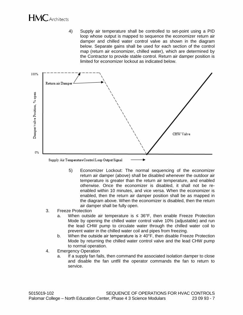
5015019-102 SEQUENCE OF OPERATIONS FOR HVAC CONTROLS Palomar College – North Education Center, Phase 4 3 Science Modulars 23 09 93 - 7
4) Supply air temperature shall be controlled to set-point using a PID loop whose output is mapped to sequence the economizer return air damper and chilled water control valve as shown in the diagram below. Separate gains shall be used for each section of the control map (return air economizer, chilled water), which are determined by the Contractor to provide stable control. Return air damper position is limited for economizer lockout as indicated below.
5) Economizer Lockout: The normal sequencing of the economizer return air damper (above) shall be disabled whenever the outdoor air temperature is greater than the return air temperature, and enabled otherwise. Once the economizer is disabled, it shall not be re-enabled within 10 minutes, and vice versa. When the economizer is enabled, then the return air damper position shall be as mapped in the diagram above. When the economizer is disabled, then the return air damper shall be fully open.
3. Freeze Protection a. When outside air temperature is ≤ 36°F, then enable Freeze Protection
Mode by opening the chilled water control valve 10% (adjustable) and run the lead CHW pump to circulate water through the chilled water coil to prevent water in the chilled water coil and pipes from freezing.
b. When the outside air temperature is ≥ 40°F, then disable Freeze Protection Mode by returning the chilled water control valve and the lead CHW pump to normal operation.
4. Emergency Operation a. If a supply fan fails, then command the associated isolation damper to close
and disable the fan untfil the operator commands the fan to return to service.
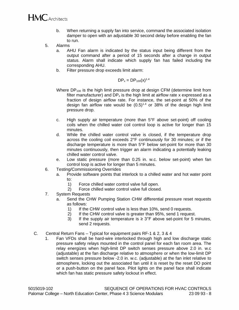
5015019-102 SEQUENCE OF OPERATIONS FOR HVAC CONTROLS Palomar College – North Education Center, Phase 4 3 Science Modulars 23 09 93 - 8
b. When returning a supply fan into service, command the associated isolation damper to open with an adjustable 30 second delay before enabling the fan to run.
5. Alarms a. AHU Fan alarm is indicated by the status input being different from the
output command after a period of 15 seconds after a change in output status. Alarm shall indicate which supply fan has failed including the corresponding AHU.
b. Filter pressure drop exceeds limit alarm:
DPx = DP100(x)1.4
Where DP100 is the high limit pressure drop at design CFM (determine limit from filter manufacturer) and DPx is the high limit at airflow rate x expressed as a fraction of design airflow rate. For instance, the set-point at 50% of the design fan airflow rate would be (0.5)1.4 or 38% of the design high limit pressure drop.
c. High supply air temperature (more than 5°F above set-point) off cooling
coils when the chilled water coil control loop is active for longer than 15 minutes.
d. While the chilled water control valve is closed, if the temperature drop across the cooling coil exceeds 2°F continuously for 30 minutes; or if the discharge temperature is more than 5°F below set-point for more than 30 minutes continuously, then trigger an alarm indicating a potentially leaking chilled water control valve.
e. Low static pressure (more than 0.25 in. w.c. below set-point) when fan control loop is active for longer than 5 minutes.
6. Testing/Commissioning Overrides a. Provide software points that interlock to a chilled water and hot water point
to: 1) Force chilled water control valve full open. 2) Force chilled water control valve full closed.
7. System Requests a. Send the CHW Pumping Station CHW differential pressure reset requests
as follows: 1) If the CHW control valve is less than 10%, send 0 requests. 2) If the CHW control valve is greater than 95%, send 1 request. 3) If the supply air temperature is ≥ 3°F above set-point for 5 minutes,
send 2 requests.
C. Central Return Fans – Typical for equipment pairs RF-1 & 2, 3 & 4 1. Fan VFDs shall be hard-wire interlocked through high and low discharge static
pressure safety relays mounted in the control panel for each fan room area. The relay energizes when high-limit DP switch senses pressure above 2.0 in. w.c (adjustable) at the fan discharge relative to atmosphere or when the low-limit DP switch senses pressure below -2.0 in. w.c. (adjustable) at the fan inlet relative to atmosphere, locking out the associated fan until it is reset by the reset DO point or a push-button on the panel face. Pilot lights on the panel face shall indicate which fan has static pressure safety lockout in effect.
5015019-102 SEQUENCE OF OPERATIONS FOR HVAC CONTROLS Palomar College – North Education Center, Phase 4 3 Science Modulars 23 09 93 - 9
2. Return fans operate whenever associated air handling unit is proven on. 3. Return fan speed shall be controlled to maintain return fan discharge static
pressure at set-point. The set-point shall be reset linearly based on building static pressure loop output from RFSPmin at 50% loop output to RFSPmax at 100% of loop output. See figure below. Set-points are determined in conjunction with the air balancer as follows: a. RFSPmin: That required to deliver the design return air volume across the
return air damper when the supply fan is at design airflow, but no less than 0.01 in. w.c.
b. RFSPmax. That required to exhaust enough air to maintain space pressure at set-point (0.05 in. w.c.) when the supply air fan is at design airflow and on 100% outdoor air.
4. Relief Dampers a. Relief dampers shall be enabled when the associated supply fan is proven
on. The relief dampers shall be closed when disabled. b. Building static pressure shall be time averaged with a sliding 5-minute
window (to dampen fluctuations). The averaged value shall be that displayed and used for control.
c. When relief dampers are enabled, a PID loop shall modulate relief dampers in sequence with the return fan static pressure set-point as shown in the figure above to maintain 0.05 in. w.c. building static pressure. Due to the potential for interaction between the building pressurization and return fan control loops, extra care must be taken in selecting the PID gains. To prevent excessive control loop interaction, the closed loop response time of the building pressurization loop should not exceed 1/5 of the closed loop response time of the return fan control loop. This can be accomplished by decreasing the gain of the building pressurization controller. The relief dampers associated with RF-1 & 2 have a dedicated building pressure

5015019-102 SEQUENCE OF OPERATIONS FOR HVAC CONTROLS Palomar College – North Education Center, Phase 4 3 Science Modulars 23 09 93 - 10
sensor. The relief dampers associated with RF-3 & 4 have a separate dedicated building pressure sensor. See mechanical drawings.
5. Emergency Operation a. If a return fan fails, then command the associated isolation damper to close
and disable the fan until the operator commands the fan to return to service.
b. When returning a return fan into service, command the associated isolation damper to open with an adjustable 30 second delay before enabling the fan to run.
6. Alarms a. Return fan alarm is indicated by the status input being different from the
output command after a period of 15 seconds after a change in output status. Alarm shall indicate which return fan has failed.
b. Low static pressure (more than 0.25 in. w.c. below set-point) when fan control loop is active for longer than 5 minutes. Alarm shall indicate which return fan pair this applies to (e.g. RF-1 & 2 or RF-3 & 4).
c. High building pressure (more than 0.1 in. w.c.). Alarm shall indicate which return fan pair that this applies to (e.g. RF-1 & 2 or RF-3 & 4).
d. Low building pressure (less than 0.0 in. w.c.). Alarm shall indicate which return fan pair that this applies to (e.g. RF-1 & 2 or RF-3 & 4).
D. Supply Terminal Units 1. See Paragraph 1.04 K. above for set-points, loops, control modes, alarms, etc.
a. If supply air temperature from air handling unit is greater than room temperature, then Cooling Mode shall be locked out.
2. Design airflow rates shall be as scheduled on plans. a. Zone maximum cooling airflow set-point (SAcool-max) b. Zone maximum heating airflow set-point (SAheat-max) c. Zone occupied minimum airflow set-point (SAocc-min) d. Zone unoccupied minimum airflow set-point (SAunocc-min)
3. Occupancy Control for Airflow Set-Point a. If there is no occupancy sensor, then zone minimum shall be the SAocc-
min. b. If there is an occupancy sensor,
1) When the occupancy sensor is triggered, the system shall control minimum airflow using the SAocc-min airflow set-point.
2) When the occupancy sensor is not triggered, the system shall control minimum airflow using the SAunocc-min airflow set-point.
4. Control logic is depicted schematically in the figure below and described in the following sections.

5015019-102 SEQUENCE OF OPERATIONS FOR HVAC CONTROLS Palomar College – North Education Center, Phase 4 3 Science Modulars 23 09 93 - 11
a. When the zone is in the Cooling Mode, the Cooling Loop output shall be mapped to the airflow set-point from the cooling maximum to the minimum airflow set-points. Heating hot water control valve is closed unless the supply air temperature is below minimum set-point – see logic below.
b. When the zone is in Dead-band Mode, the airflow set-point shall be the minimum airflow set-point. Heating hot water control valve is closed unless the supply air temperature is below minimum set-point – see logic below.
c. When the zone is in the Heating Mode, the Heating Loop shall maintain space temperature at the heating set-point as follows. 1) From 0 – 33%, the Heating Loop output shall reset the discharge
temperature from 55°F to 95°F. 2) From 34 – 66%, the Heating Loop output shall reset the zone airflow
set-point from the minimum airflow set-point to the maximum airflow set-point.
3) From 67% - 100%, the Heating Loop output shall reset the discharge temperature from 95°F to 115°F.
4) The heating hot water control valve shall be modulated using P + I loop to maintain the discharge air temperature at set-point. Directly controlling the heating hot water control valve off zone temperature PID loop is not acceptable.
d. In and mode, the heating hot water valve shall be modulated to maintain a supply air temperature no lower than 55°F. (This is to prevent overly cold supply air temperatures during cold outdoor conditions).
e. The VAV damper shall be modulated to maintain the measured airflow at set-point.
5. Alarms
5015019-102 SEQUENCE OF OPERATIONS FOR HVAC CONTROLS Palomar College – North Education Center, Phase 4 3 Science Modulars 23 09 93 - 12
a. Supply airflow alarm, alarm if airflow is 30 CFM or 30% below set-point, whichever is greater. 1) Delay Time: 5 minutes.
b. High supply air temperature alarm, alarm if supply air temperature is ≥ 10°F above set-point.
c. Low supply air temperature alarm, alarm is supply air temperature is ≥ 20°F below set-point or is below 50°F.
6. System Requests a. Cooling SAT Reset Requests
1) If the Cooling Loop is less than 85%, send 0 requests. 2) If the Cooling Loop is greater than 95%, send 1 request. 3) If the zone temperature exceeds the zone’s cooling set-point by 3°F
for 2 minutes, send 2 requests. 4) If the zone temperature exceeds the zone’s cooling set-point by 5°F
for 2 minutes, send 3 requests. b. Static Pressure Reset Requests
1) If the Damper Loop is less than 85%, send 0 requests. 2) If the Damper Loop is greater than 95%, send 1 request. 3) If the measured airflow is less than 90% of set-point for 1 minute,
send 2 requests. 4) If the measured airflow is less than 75% of set-point for 1 minute,
send 3 requests. c. Heating Hot Water Reset Requests
1) If the heating hot water control valve is less than 85%, send 0 requests.
2) If the heating hot water control valve is greater than 95%, send 1 request.
3) If the supply air temperature is 10°F less than set-point for 5 minutes, send 2 requests.
4) If the supply air temperature if 15°F less than set-point for 5 minutes, send 3 requests.
d. HHW DP Requests 1) If the HHW valve is less than 10%, send 0 requests. 2) If the HHW valve is greater than 95%, send 1 request.
E. Non-Lab Exhaust Terminal Units 1. Design airflow rates shall be as scheduled on plans. 2. Control Logic
a. Non-lab exhaust terminal units shall modulate to achieve a static airflow set-point value (adjustable).
3. Alarms a. Exhaust airflow alarm, alarm if airflow 30 CFM or 30% below set-point,
whichever is greater. 1) Delay Time: 5 minutes.
4. Static Pressure Reset Requests a. If the Damper Loop is less than 85%, send 0 requests. b. If the Damper Loop is greater than 95%, send 1 request. c. If the measured airflow is less than 90% of set-point for 1 minute, send 2
requests.
5015019-102 SEQUENCE OF OPERATIONS FOR HVAC CONTROLS Palomar College – North Education Center, Phase 4 3 Science Modulars 23 09 93 - 13
d. If the measured airflow is less than 75% of set-point for 1 minute, send 3 requests.
F. Lab Exhaust Terminal Units 1. Design airflow rates shall be as scheduled on plans. 2. Control logic shall be as follows:
a. Airflow set-point shall equal to the sum of the airflow set-points of supply terminal units serving the same area plus a pressurization offset. See terminal unit airflow balance schedule on mechanical drawings.
3. Alarms a. Exhaust airflow alarm, alarm if airflow 30 CFM or 30% below set-point,
whichever is greater. 1) Delay Time: 5 minutes.
b. Zone airflow offset alarm, alarm if airflow offset deviates from set-point by more than 10%. 1) Delay Time: 5 minutes.
4. Static Pressure Reset Requests a. If the Damper Loop is less than 85%, send 0 requests. b. If the Damper Loop is greater than 95%, send 1 request. c. If the measured airflow is less than 90% of set-point for 1 minute, send 2
requests. d. If the measured airflow is less than 75% of set-point for 1 minute, send 3
requests.
G. Anatomy Labs (Typical of Rooms 230 & 233) 1. Supply air valve control, see Item F above. 2. General exhaust valve control, see Item H above. 3. Normal Operation
a. The supply valve, general exhaust valve, and downdraft table valve shall modulate to meet the greater demand of either thermal load or minimum ventilation. See the airflow balance schedule for airflow parameters.
b. Minimum ventilation requirements are determined based on whether or not the occupancy sensor has been triggered and whether or not the ventilation override switch has been triggered. See the airflow balance schedule for occupied, unoccupied, and ventilation override airflow parameters.
4. Ventilation Override Mode of Operation
a. Each anatomy lab room shall be provided with a local user override switch to trigger Ventilation Override Mode of Operation for an adjustable amount of time (default = 2 hours).
b. When Ventilation Override Mode is triggered, the supply valve, general exhaust valve, and downdraft table exhaust valve shall modulate to achieve the airflow values shown on the air balance table corresponding with Ventilation Override Mode. The intent of this mode of operation is to provide a temporary increase in room ventilation to address room activities that the user has deemed appropriate for higher rates of ventilation.
c. When the adjustable time frame for Ventilation Override Mode has expired, return the supply valve, general exhaust valve, and downdraft table exhaust valve to Normal Operation.
H. Fume Hood Labs

5015019-102 SEQUENCE OF OPERATIONS FOR HVAC CONTROLS Palomar College – North Education Center, Phase 4 3 Science Modulars 23 09 93 - 14
1. Supply air valve control, see Item F above. 2. General exhaust valve control, see Item H above. 3. Fume hood exhaust valve control
a. Damper is modulated by factory controller to maintain fume hood exhaust airflow set-point.
b. Fume hood exhaust airflow set-point is calculated by factory fume hood controller: 1) If the fume hood is not equipped with a zone presence sensor, then
the fume hood controller shall calculate airflow set-point required to maintain sash velocity of 100 feet per minute.
2) If the fume hood is equipped with a zone presence sensor, then the fume hood controller shall calculate airflow set-point required based on occupant presence immediately in front of the hood. If an occupant is detected immediately in front of the hood, then the fume hood controller shall calculate airflow set-point required to maintain sash velocity of 100 feet per minute. If no occupant is detected immediately in front of the hood, then the fume hood controller shall calculate airflow set-point required to maintain a reduced sash velocity as determined appropriate through ASHRAE Standard 110 testing and approval by the owner’s environmental health and safety representative. The reduced sash velocity shall be no less than 60 feet per minute.
4. Alarms a. Fume hood controller alarm, monitor the fume hood controller for alarm
status and generate an alarm when the fume hood controller alarm is triggered.
5. Static Pressure Reset Requests a. If the Damper Loop is less than 75%, send 0 requests. b. If the Damper Loop is greater than 85%, send 1 request. c. If the measured airflow is less than 95% of set-point for 1 minute, send 2
requests. d. If the measured airflow is less than 85% of set-point for 1 minute, send 3
requests.
I. Exhaust Fans EF-1, 2, & 3 1. Normal Operation
a. EF-1, 2, & 3 shall be staged as shown in the table below based on a function of aggregate airflow measured through all building exhaust terminal units. Each exhaust fan is driven by a dedicated VFD and controlled to maintain an exhaust plenum static pressure set-point. All running exhaust fans shall receive the same speed signal.
Stage Description Stage Up [CFM] Stage Down [CFM]
1 1 Fan Running 32,000 -
2 2 Fans Running 60,000 27,000
3 3 Fans Running - 50,000
b. Rotate between EF-1, 2, & 3 to achieve equal run-time based on total
accumulated run-hours.

5015019-102 SEQUENCE OF OPERATIONS FOR HVAC CONTROLS Palomar College – North Education Center, Phase 4 3 Science Modulars 23 09 93 - 15
c. Exhaust fan VFDs shall be hard-wire interlocked through a low air static pressure safety relay mounted in the control panel at the fan area on the roof. The relay energizes when the low-limit DP switches sense pressure below -4.5 in. w.c. (adjustable) at the fan inlet locking out the fan until it is reset by the reset DO point or a push-button on the panel face. A pilot light on the panel face indicates static pressure safety lockout is in effect.
d. Exhaust fan speed loop output shall be mapped to the VFD speed from 10% minimum VFD speed to 100% speed. Start to open isolation damper when fan reaches minimum speed (delay is to ensure fan is on before damper opens to prevent backflow from the other fan from back-wheeling the fan prior to startup). Close the isolation damper when the fan status indicates that the fan is off. Adjust rate of closing and opening when fan stops to prevent damage to ductwork.
2. Fire Alarm Operation a. When the fire alarm relay is triggered, open the fire alarm bypass dampers
fully for EF-1, 2, & 3 and disable all exhaust fans from running. The intent of this sequence is to neutralize negative pressure in the exhaust system as quickly as possible to facilitate egress from the building and prevent excessively high door pull force requirements.
b. When the fire alarm has been reset and restored to normal operation, close the fire alarm bypass dampers and return the exhaust fans to normal operation.
3. Static Pressure Set-Point Reset a. Static pressure set-point: Set-point shall be reset using Trim & Respond
logic (see Paragraph 1.04 J.) with the following parameters:
Variable Value
SP0 -1.25 in .w.c
SPmin -0.75 in. w.c.
SPmax -3.75 in. w.c.
Td 5 minutes
T 1 minutes
I 0
R Zone Static Pressure Requests
SPtrim 0.05 in. w.c.
SPres -0.06 in. w.c.
SPres-max -0.25 in. w.c.
4. Alarms
a. Exhaust Fan Status Alarm for no proof of fan 1) Delay Time: 5 minutes.
b. Exhaust Air Static Alarm 1) Delay Time: 5 minutes.
J. HHW Plant 1. Condensing Boilers B-1, 2, & 3

5015019-102 SEQUENCE OF OPERATIONS FOR HVAC CONTROLS Palomar College – North Education Center, Phase 4 3 Science Modulars 23 09 93 - 16
a. Boilers shall be lead/lag alternated to achieve equal run-time based on total accumulated run-hours.
b. Lead Boiler 1) The lead boiler shall be enabled if:
a) The outdoor air temperature is less than a lockout temperature of 75°F (adjustable), and
b) There are more than 0 (adjustable) HHW plant requests for more than 3 minutes.
2) When the lead boiler is enabled, first start the lead pump and simultaneously open the lead boiler’s isolation valve, then after 45 seconds, start the lead boiler via the Modbus interface.
3) The lead boiler shall be disabled if it has run at least 10 minutes and either: a) The outdoor air temperature is greater than 3°F above the
lockout set-point; or b) There are 0 HHW plant requests.
4) When the lead boiler is disabled, first stop the boiler via the Modbus interface, then after 3 minutes turn off the lead pump and simultaneously close the boiler isolation valve.
c. Lag Boilers 1) The next lag boiler shall be enabled if:
a) The lead boiler is enabled and b) The firing rate of operating boilers exceeds (N+1)*boiler
minimum firing rate for 10 minutes, where N is the current number of operating boilers. Boiler firing rate shall be passed through Modbus interface. Minimum firing rate shall be per manufacturer’s submittal or 10%, whichever is higher.
2) When the next lag boiler is enabled, open its isolation valve, then after 45 seconds, start the next lag boiler via the Modbus interface.
3) The last lag boiler shall be disabled if: a) The lead boiler is disabled or b) The lag system has run at least 10 minutes and the average
boiler firing rate is less than minimum firing rate. 4) When a lag boiler is disabled, first stop the boiler via the Modbus
interface, then after 3 minutes close the boiler isolation valve. d. Hot Water Supply Temperature Reset
1) Heating hot water temperature set-point shall be reset using Trim & Respond logic (see Paragraph 1.04 J.) based on heating hot water pump status with the following parameters:
Variable Value
SP0 SPmax
SPmin 90°F
SPmax 140°F
Td 10 minutes
T 5 minutes
I 0
R Heating HWST Reset Requests
SPtrim -2°F
5015019-102 SEQUENCE OF OPERATIONS FOR HVAC CONTROLS Palomar College – North Education Center, Phase 4 3 Science Modulars 23 09 93 - 17
SPres +3°F
SPres-max +7°F
e. While boiler is enabled and at least one HHW pump is proven on, control
leaving heating hot water temperature at set-point using a PID loop with an output ranging from 0 to 100%.
2. HHW Pumps HHWP-1 & HHWP-2 a. The HHW pumps shall be lead/lag alternated to achieve equal run-time
based on total accumulated run-hours. b. The pumping system shall be enabled when there are more than zero
(adjustable) HHW plant requests and shall be disabled otherwise. c. When the pumping system is enabled, the HHW DP control loop is enabled.
The loop shall be a reverse-acting loop maintaining the differential pressure (DP) sensor at set-point.
d. Differential pressure set-point shall be reset using Trim & Respond logic (see Paragraph 1.04 J.) based on HHW pump status with the following parameters. DP-MAX is the design DP set-point determined in conjunction with the balancing contractor.
Variable Value
SP0 DP-MAX
SPmin 1 PSI
SPmax DP-MAX
Td 15 minutes
T 5 minutes
I 0
R HHW DP Reset Requests
SPtrim -2%
SPres +3%
SPres-max +7%
e. When the lead pump speed exceeds 90% for 2 minutes, the lag pump shall
start. Both pumps shall receive the same speed signal when both are on. Each HHW pump is driven by a dedicated VFD and controlled to maintain the DP set-point. The
3. Minimum Flow Control a. When any HHW pump is proven on, the bypass valve shall be enabled, and
closed otherwise. Bypass valve shall be modulated to maintain minimum flow as measured by the flow meter at set-point equal to the minimum water flow rates required by the operating boilers. Minimum flow rates are as follows:
# of Boilers Enabled Minimum HHW Flow [GPM]
1 25
2 50
3 75
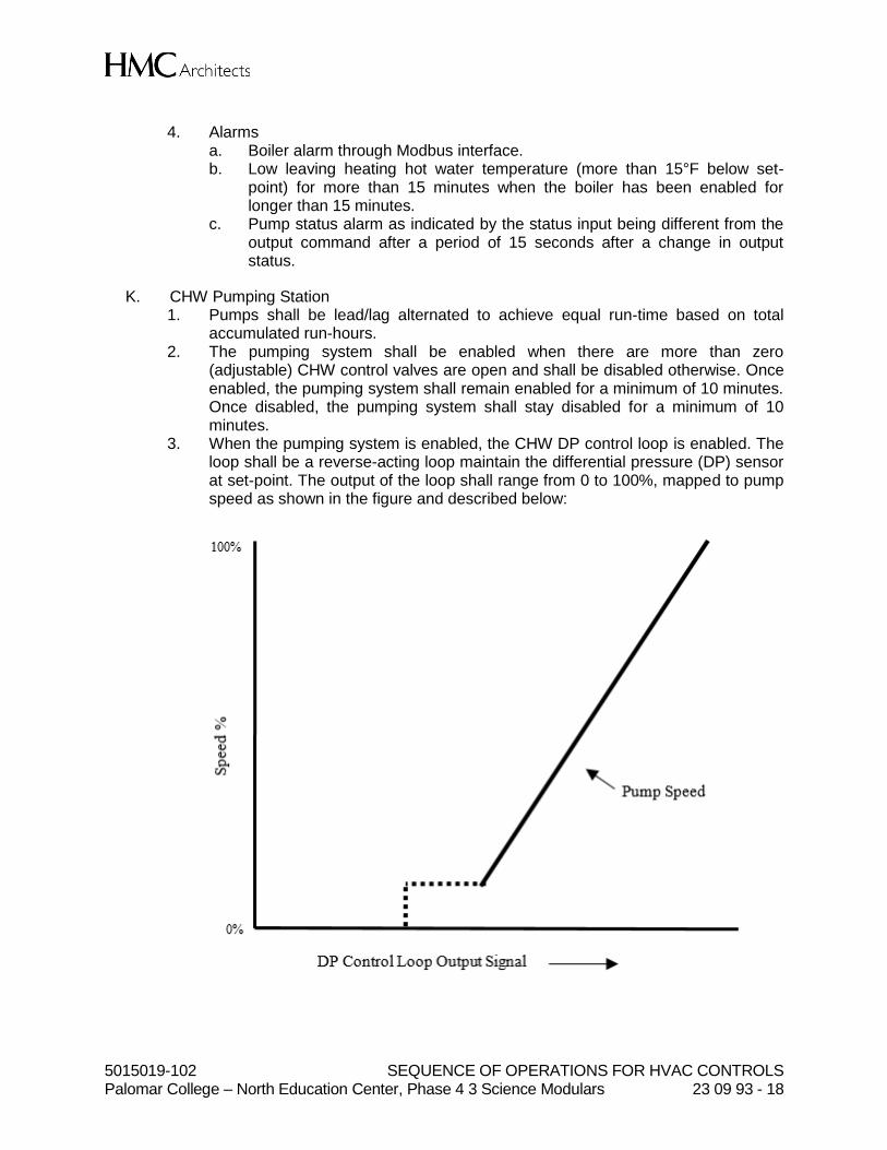
5015019-102 SEQUENCE OF OPERATIONS FOR HVAC CONTROLS Palomar College – North Education Center, Phase 4 3 Science Modulars 23 09 93 - 18
4. Alarms
a. Boiler alarm through Modbus interface. b. Low leaving heating hot water temperature (more than 15°F below set-
point) for more than 15 minutes when the boiler has been enabled for longer than 15 minutes.
c. Pump status alarm as indicated by the status input being different from the output command after a period of 15 seconds after a change in output status.
K. CHW Pumping Station 1. Pumps shall be lead/lag alternated to achieve equal run-time based on total
accumulated run-hours. 2. The pumping system shall be enabled when there are more than zero
(adjustable) CHW control valves are open and shall be disabled otherwise. Once enabled, the pumping system shall remain enabled for a minimum of 10 minutes. Once disabled, the pumping system shall stay disabled for a minimum of 10 minutes.
3. When the pumping system is enabled, the CHW DP control loop is enabled. The loop shall be a reverse-acting loop maintain the differential pressure (DP) sensor at set-point. The output of the loop shall range from 0 to 100%, mapped to pump speed as shown in the figure and described below:

5015019-102 SEQUENCE OF OPERATIONS FOR HVAC CONTROLS Palomar College – North Education Center, Phase 4 3 Science Modulars 23 09 93 - 19
4. From 0% to 50%, the CHW pumps shall remain off and available campus distribution differential pressure shall be utilized.
5. As the DP loop signal ranges from 50% to 100%, the lead pump shall start and its speed mapped from its minimum speed to 100% as shown in the figure. The lead pump shall stop when the DP loop is below 50% and the pump has run for a minimum of 5 minutes.
L. Variable-Speed Two-Pipe Fan Coil Units 1. Fan control
a. The fan shall run when zone is in Cooling Mode. Demand for cooling is when room temperature is 78˚F or higher (adjustable). It shall be off otherwise.
2. Supply Fan Speed and Supply Air Temperature Set-Point Control a. When the supply fan is proven on, supply air temperature and fan speed
set-points shall be as follows:
1) When the zone served by the system is in Cooling Mode, supply air temperature shall be reset from dead-band SAT set-point at 0% cooling Loop output signal down to Minimum SAT set-point at 50% PID signal. Fan speed shall be reset from Minimum Speed at 50% cooling PID signal and below, proportionally up to Maximum Cooling Speed at 100% cooling PID signal.
2) Supply air temperature set-point endpoints (all adjustable from graphic) a) Maximum SAT set-point = Current cooling space temperature
set-point. b) Minimum SAT set-point = Design cooling coil leaving air
temperature. 3) Speed set-point endpoints (all adjustable from graphic)
a) Maximum Cooling Speed: that required to deliver design airflow to the zone; coordinate with air balancer.

5015019-102 SEQUENCE OF OPERATIONS FOR HVAC CONTROLS Palomar College – North Education Center, Phase 4 3 Science Modulars 23 09 93 - 20
b) Minimum Speed: 30% of maximum cooling speed. 3. Supply Air Temperature Control
a. Control loop is enabled when the supply air fan is proven on, and disabled and output set to zero otherwise.
b. Supply air temperature shall be controlled to set-point using a PID loop whose output is the chilled water control valve. Provide a ramp function to prevent rapid changes in valve position (more than 5% per minute, adjustable) to prevent sudden pressure changes in the CHW flow distribution system and erratic control.
4. Testing/Commissioning Overrides a. Force chilled water control valve full open. b. Force chilled water control valve full closed.
5. System Requests a. Chilled Water DP Requests
1) If the CHW control valve is less than 10%, send 0 requests 2) If the CHW control valve is greater than 95%, send 1 request
6. Alarms a. Fan alarm is indicated by the status input being different from the output
command after a period of 15 seconds after a change in output status. 1) Commanded on, status off 2) Commanded off, status on
b. High supply air temperature (more than 5°F above set-point) off cooling coils when chilled water control valve loop is active for longer than 5 minutes.
M. Domestic & Industrial Water Heater Plants 1. Recirculation pump shall operate when any of the zones serving occupied
spaces (not the 24-hour zones with only equipment) serving the area that includes the toilet rooms served by the recirculation pump is in Occupied Mode.
2. Alarms
a. Pump alarm is indicated by the status input being different from the output command after a period of 15 seconds after a change in output status. 1) Commanded on, status off 2) Commanded off, status on
b. Hot water supply temperature less than 110°F when recirculation pump is proven on for 15 minutes.
PART 2 - PRODUCTS (Not Applicable)
PART 3 - EXECUTION (Not Applicable)
END OF SECTION
5015019-102 METAL DUCTS Palomar College – North Education Center, Phase 4 3 Science Modulars 23 31 13 - 1
SECTION 23 31 13
METAL DUCTS
PART 1 - GENERAL
1.01 RELATED DOCUMENTS
A. Drawings and general provisions of the Contract, including General and Supplementary Conditions and Division 01 Specification Sections, apply to this Section.
1.02 SUMMARY
A. Section Includes: 1. Single-wall rectangular ducts and fittings. 2. Single-wall round ducts and fittings. 3. Sheet metal materials. 4. Duct liner. 5. Sealants and gaskets. 6. Hangers and supports. 7. Seismic-restraint devices.
B. Related Sections: 1. Section 230593 "Testing, Adjusting, and Balancing for HVAC" for testing,
adjusting, and balancing requirements for metal ducts. 2. Section 233300 "Air Duct Accessories" for dampers, sound-control devices, duct-
mounting access doors and panels, turning vanes, and flexible ducts.
1.03 PERFORMANCE REQUIREMENTS
A. Delegated Duct Design: Duct construction, including sheet metal thicknesses, seam and joint construction, reinforcements, and hangers and supports, shall comply with SMACNA's "HVAC Duct Construction Standards - Metal and Flexible" and performance requirements and design criteria indicated in "Duct Schedule" Article.
B. Structural Performance: Duct hangers and supports and seismic restraints shall withstand the effects of gravity and seismic loads and stresses within limits and under conditions described in SMACNA's "HVAC Duct Construction Standards - Metal and Flexible" and ASCE/SEI 7. SMACNA's "Seismic Restraint Manual: Guidelines for Mechanical Systems." 1. Seismic Hazard Level A: Seismic force to weight ratio, 0.48. 2. Seismic Hazard Level B: Seismic force to weight ratio, 0.30. 3. Seismic Hazard Level C: Seismic force to weight ratio, 0.15.
C. Airstream Surfaces: Surfaces in contact with the airstream shall comply with requirements in ASHRAE 62.1.

5015019-102 METAL DUCTS Palomar College – North Education Center, Phase 4 3 Science Modulars 23 31 13 - 2
1.04 ACTION SUBMITTALS
A. Product Data: For each type of the following products: 1. Liners and adhesives. 2. Sealants and gaskets. 3. Seismic-restraint devices.
B. LEED Submittals: 1. Product Data for Prerequisite IEQ 1: Documentation indicating that duct systems
comply with ASHRAE 62.1, Section 5 - "Systems and Equipment." 2. Product Data for Prerequisite EA 2: Documentation indicating that duct systems
comply with ASHRAE/IESNA 90.1, Section 6.4.4 - "HVAC System Construction and Insulation."
3. Leakage Test Report for Prerequisite EA 2: Documentation of work performed for compliance with ASHRAE/IESNA 90.1, Section 6.4.4.2.2 - "Duct Leakage Tests."
4. Duct-Cleaning Test Report for Prerequisite IEQ 1: Documentation of work performed for compliance with ASHRAE 62.1, Section 7.2.4 - "Ventilation System Start-up."
5. Product Data for Credit IEQ 4.1: For adhesives and sealants, documentation including printed statement of VOC content.
6. Laboratory Test Reports for Credit IEQ 4: For adhesives and sealants, documentation indicating that products comply with the testing and product requirements of the California Department of Health Services' "Standard Practice for the Testing of Volatile Organic Emissions from Various Sources Using Small-Scale Environmental Chambers."
C. Shop Drawings: 1. Fabrication, assembly, and installation, including plans, elevations, sections,
components, and attachments to other work. 2. Factory- and shop-fabricated ducts and fittings. 3. Duct layout indicating sizes, configuration, liner material, and static-pressure
classes. 4. Elevation of top of ducts. 5. Dimensions of main duct runs from building grid lines. 6. Fittings. 7. Reinforcement and spacing. 8. Seam and joint construction. 9. Penetrations through fire-rated and other partitions. 10. Equipment installation based on equipment being used on Project. 11. Locations for duct accessories, including dampers, turning vanes, and access
doors and panels. 12. Hangers and supports, including methods for duct and building
attachment, seismic restraints, and vibration isolation.
D. Delegated-Design Submittal: 1. Sheet metal thicknesses. 2. Joint and seam construction and sealing. 3. Reinforcement details and spacing. 4. Materials, fabrication, assembly, and spacing of hangers and supports.
5015019-102 METAL DUCTS Palomar College – North Education Center, Phase 4 3 Science Modulars 23 31 13 - 3
5. Design Calculations: Calculations, including analysis data signed and sealed by the qualified professional engineer responsible for their preparation for selecting hangers and supports and seismic restraints.
1.05 INFORMATIONAL SUBMITTALS
A. Coordination Drawings: Plans, drawn to scale, on which the following items are shown and coordinated with each other, using input from installers of the items involved: 1. Duct installation in congested spaces, indicating coordination with general
construction, building components, and other building services. Indicate proposed changes to duct layout.
2. Suspended ceiling components. 3. Structural members to which duct will be attached. 4. Size and location of initial access modules for acoustical tile. 5. Penetrations of smoke barriers and fire-rated construction. 6. Items penetrating finished ceiling including the following:
a. Lighting fixtures. b. Air outlets and inlets. c. Speakers. d. Sprinklers. e. Access panels. f. Perimeter moldings.
B. Welding certificates.
C. Field quality-control reports.
1.06 QUALITY ASSURANCE
A. Welding Qualifications: Qualify procedures and personnel according to the following: 1. AWS D1.1/D1.1M, "Structural Welding Code - Steel," for hangers and supports. 2. AWS D1.2/D1.2M, "Structural Welding Code - Aluminum," for aluminum
supports. 3. AWS D9.1M/D9.1, "Sheet Metal Welding Code," for duct joint and seam welding.
B. ASHRAE Compliance: Applicable requirements in ASHRAE 62.1, Section 5 - "Systems and Equipment" and Section 7 - "Construction and System Start-up."
C. ASHRAE/IESNA Compliance: Applicable requirements in ASHRAE/IESNA 90.1, Section 6.4.4 - "HVAC System Construction and Insulation."
PART 2 - PRODUCTS
2.01 SINGLE-WALL RECTANGULAR DUCTS AND FITTINGS
A. General Fabrication Requirements: Comply with SMACNA's "HVAC Duct Construction Standards - Metal and Flexible" based on indicated static-pressure class unless otherwise indicated.
B. Transverse Joints: Select joint types and fabricate according to SMACNA's "HVAC Duct Construction Standards - Metal and Flexible," Figure 2-1, "Rectangular
5015019-102 METAL DUCTS Palomar College – North Education Center, Phase 4 3 Science Modulars 23 31 13 - 4
Duct/Transverse Joints," for static-pressure class, applicable sealing requirements, materials involved, duct-support intervals, and other provisions in SMACNA's "HVAC Duct Construction Standards - Metal and Flexible."
C. Longitudinal Seams: Select seam types and fabricate according to SMACNA's "HVAC Duct Construction Standards - Metal and Flexible," Figure 2-2, "Rectangular Duct/Longitudinal Seams," for static-pressure class, applicable sealing requirements, materials involved, duct-support intervals, and other provisions in SMACNA's "HVAC Duct Construction Standards - Metal and Flexible."
D. Elbows, Transitions, Offsets, Branch Connections, and Other Duct Construction: Select types and fabricate according to SMACNA's "HVAC Duct Construction Standards - Metal and Flexible," Chapter 4, "Fittings and Other Construction," for static-pressure class, applicable sealing requirements, materials involved, duct-support intervals, and other provisions in SMACNA's "HVAC Duct Construction Standards - Metal and Flexible."
2.2 SINGLE-WALL ROUND DUCTS AND FITTINGS
A. General Fabrication Requirements: Comply with SMACNA's "HVAC Duct Construction Standards - Metal and Flexible," Chapter 3, "Round, Oval, and Flexible Duct," based on indicated static-pressure class unless otherwise indicated. 1. Factory- or shop-fabricated spiral lock seam duct:
a. No snap lock b. Factory-fabricated longitudinal seam acceptable for ducts larger than
standard factory sizes 2. Manufacturers:
a. United Sheet Metal Division, United McGill b. Semco Manufacturing, Inc. c. Or equal
B. Flat-Oval Ducts: Indicated dimensions are the duct width (major dimension) and diameter of the round sides connecting the flat portions of the duct (minor dimension).
C. Transverse Joints: Select joint types and fabricate according to SMACNA's "HVAC Duct Construction Standards - Metal and Flexible," Figure 3-1, "Round Duct Transverse Joints," for static-pressure class, applicable sealing requirements, materials involved, duct-support intervals, and other provisions in SMACNA's "HVAC Duct Construction Standards - Metal and Flexible." 1. Transverse Joints in Ducts Larger Than 60 Inches in Diameter: Flanged.
D. Longitudinal Seams: Select seam types and fabricate according to SMACNA's "HVAC Duct Construction Standards - Metal and Flexible," Figure 3-2, "Round Duct Longitudinal Seams," for static-pressure class, applicable sealing requirements, materials involved, duct-support intervals, and other provisions in SMACNA's "HVAC Duct Construction Standards - Metal and Flexible." 1. Fabricate round ducts larger than 90 inches in diameter with butt-welded
longitudinal seams. 2. Fabricate flat-oval ducts larger than 72 inches in width (major dimension) with
butt-welded longitudinal seams.

5015019-102 METAL DUCTS Palomar College – North Education Center, Phase 4 3 Science Modulars 23 31 13 - 5
E. Fittings: 1. Same material and construction as duct in which installed 2. For ductwork exposed to occupant view, do not use fabricated fittings at taps to
terminal units and outlets. Instead use saddle tap cut into continuous spiral duct. Intent is for spiral duct to be continuous for aesthetic reasons. Saddle tap flange width shall be 0.5 inches or less.
F. Tees and Laterals: Select types and fabricate according to SMACNA's "HVAC Duct Construction Standards - Metal and Flexible," Figure 3-5, "90 Degree Tees and Laterals," and Figure 3-6, "Conical Tees," for static-pressure class, applicable sealing requirements, materials involved, duct-support intervals, and other provisions in SMACNA's "HVAC Duct Construction Standards - Metal and Flexible."
2.03 SHEET METAL MATERIALS
A. General Material Requirements: Comply with SMACNA's "HVAC Duct Construction Standards - Metal and Flexible" for acceptable materials, material thicknesses, and duct construction methods unless otherwise indicated. Sheet metal materials shall be free of pitting, seam marks, roller marks, stains, discolorations, and other imperfections.
B. Galvanized Sheet Steel: Comply with ASTM A 653/A 653M. 1. Galvanized Coating Designation: G90. 2. Finishes for Surfaces Exposed to View: Mill phosphatized.
C. PVC-Coated, Galvanized Sheet Steel: Comply with ASTM A 653/A 653M. 1. Galvanized Coating Designation: G90. 2. Coating Materials: Acceptable to authorities having jurisdiction for use on ducts
listed and labeled by an NRTL for compliance with UL 181, Class 1.
D. Carbon-Steel Sheets: Comply with ASTM A 1008/A 1008M, with oiled, matte finish for exposed ducts.
E. Stainless-Steel Sheets: Comply with ASTM A 480/A 480M, Type 304 or 316, as indicated in the "Duct Schedule" Article; cold rolled, annealed, sheet. Exposed surface finish shall be No. 2B, No. 2D, No. 3, or No. 4 as indicated in the "Duct Schedule" Article.
F. Aluminum Sheets: Comply with ASTM B 209 Alloy 3003, H14 temper; with mill finish
for concealed ducts, and standard, one-side bright finish for duct surfaces exposed to view.
G. Factory- or Shop-Applied Antimicrobial Coating: 1. Apply to the surface of sheet metal that will form the interior surface of the duct.
An untreated clear coating shall be applied to the exterior surface. 2. Antimicrobial compound shall be tested for efficacy by an NRTL and registered
by the EPA for use in HVAC systems. 3. Coating containing the antimicrobial compound shall have a hardness of 2H,
minimum, when tested according to ASTM D 3363.
5015019-102 METAL DUCTS Palomar College – North Education Center, Phase 4 3 Science Modulars 23 31 13 - 6
4. Surface-Burning Characteristics: Maximum flame-spread index of 25 and maximum smoke-developed index of 50 when tested according to UL 723; certified by an NRTL.
5. Shop-Applied Coating Color: Black. 6. Antimicrobial coating on sheet metal is not required for duct containing liner
treated with antimicrobial coating.
H. Reinforcement Shapes and Plates: ASTM A 36/A 36M, steel plates, shapes, and bars; black and galvanized. 1. Where black- and galvanized-steel shapes and plates are used to reinforce
aluminum ducts, isolate the different metals with butyl rubber, neoprene, or EPDM gasket materials.
I. Tie Rods: Galvanized steel, 1/4-inch minimum diameter for lengths 36 inches or less; 3/8-inch minimum diameter for lengths longer than 36 inches.
2.04 DUCT LINER
A. Fibrous-Glass Duct Liner: Comply with ASTM C 1071, NFPA 90A, or NFPA 90B; and with NAIMA AH124, "Fibrous Glass Duct Liner Standard." 1. Manufacturers: Subject to compliance with requirements, available
manufacturers offering products that may be incorporated into the Work include, but are not limited to the following: a. CertainTeed Corporation; Insulation Group b. Johns Manville c. Knauf Insulation d. Maximum Thermal Conductivity:
1) Type I, Flexible: 0.27 Btu x in./h x sq. ft. x deg F at 75 deg F mean temperature.
2) Type II, Rigid: 0.23 Btu x in./h x sq. ft. x deg F at 75 deg F mean temperature.
2. Antimicrobial Erosion-Resistant Coating: Apply to the surface of the liner that will form the interior surface of the duct to act as a moisture repellent and erosion-resistant coating. Antimicrobial compound shall be tested for efficacy by an NRTL and registered by the EPA for use in HVAC systems.
3. Water-Based Liner Adhesive: Comply with NFPA 90A or NFPA 90B and with ASTM C 916. a. For indoor applications, adhesive shall have a VOC content of 80 g/L or
less when calculated according to 40 CFR 59, Subpart D (EPA Method 24).
B. Insulation Pins and Washers: 1. Cupped-Head, Capacitor-Discharge-Weld Pins: Copper- or zinc-coated steel pin,
fully annealed for capacitor-discharge welding, 0.135-inch-diameter shank, length to suit depth of insulation indicated with integral 1-1/2-inch galvanized carbon-steel washer.
2. Insulation-Retaining Washers: Self-locking washers formed from 0.016-inch-thick stainless steel; with beveled edge sized as required to hold insulation securely in place but not less than 1-1/2 inches in diameter.
C. Shop Application of Duct Liner: Comply with SMACNA's "HVAC Duct Construction Standards - Metal and Flexible," Figure 7-11, "Flexible Duct Liner Installation."
5015019-102 METAL DUCTS Palomar College – North Education Center, Phase 4 3 Science Modulars 23 31 13 - 7
1. Adhere a single layer of indicated thickness of duct liner with at least 90 percent adhesive coverage at liner contact surface area. Attaining indicated thickness with multiple layers of duct liner is prohibited.
2. Apply adhesive to transverse edges of liner facing upstream that do not receive metal nosing.
3. Butt transverse joints without gaps, and coat joint with adhesive. 4. Fold and compress liner in corners of rectangular ducts or cut and fit to ensure
butted-edge overlapping. 5. Do not apply liner in rectangular ducts with longitudinal joints, except at corners
of ducts, unless duct size and dimensions of standard liner make longitudinal joints necessary.
6. Delete first subparagraph below if air velocities do not exceed 2500 fpm (12.7 m/s).
7. Apply adhesive coating on longitudinal seams in ducts with air velocity of 2500 fpm.
8. Securing method in first subparagraph below is for ducts with air velocities of 2500 fpm (12.7 m/s) and lower. Use caution when designing lined ducts with air velocities higher than 2500 fpm (12.7 m/s). See SMACNA for requirements.
9. Secure liner with mechanical fasteners 4 inches from corners and at intervals not exceeding 12 inches transversely; at 3 inches from transverse joints and at intervals not exceeding 18 inches longitudinally.
10. Secure transversely oriented liner edges facing the airstream with metal nosings that have either channel or "Z" profiles or are integrally formed from duct wall. Fabricate edge facings at the following locations: a. Fan discharges. b. Intervals of lined duct preceding unlined duct. c. Upstream edges of transverse joints in ducts where air velocities are higher
than 2500 fpm or where indicated.
11. Secure insulation between perforated sheet metal inner duct of same thickness as specified for outer shell. Use mechanical fasteners that maintain inner duct at uniform distance from outer shell without compressing insulation. a. Sheet Metal Inner Duct Perforations: 3/32-inch diameter, with an overall
open area of 23 percent. 12. Terminate inner ducts with buildouts attached to fire-damper sleeves, dampers,
turning vane assemblies, or other devices. Fabricated buildouts (metal hat sections) or other buildout means are optional; when used, secure buildouts to duct walls with bolts, screws, rivets, or welds.
2.05 SEALANT AND GASKETS
A. General Sealant and Gasket Requirements: Surface-burning characteristics for sealants and gaskets shall be a maximum flame-spread index of 25 and a maximum smoke-developed index of 50 when tested according to UL 723; certified by an NRTL.
B. Two-Part Tape Sealing System: 1. Tape: Woven cotton fiber impregnated with mineral gypsum and modified
acrylic/silicone activator to react exothermically with tape to form hard, durable, airtight seal.
2. Tape Width: 3 inches. 3. Sealant: Modified styrene acrylic. 4. Water resistant.
5015019-102 METAL DUCTS Palomar College – North Education Center, Phase 4 3 Science Modulars 23 31 13 - 8
5. Mold and mildew resistant. 6. Maximum Static-Pressure Class: 10-inch wg, positive and negative. 7. Service: Indoor and outdoor. 8. Service Temperature: Minus 40 to plus 200 deg F. 9. Substrate: Compatible with galvanized sheet steel (both PVC coated and bare),
stainless steel, or aluminum. 10. For indoor applications, sealant shall have a VOC content of 250 g/L or less
when calculated according to 40 CFR 59, Subpart D (EPA Method 24). 11. Sealant shall comply with the testing and product requirements of the California
Department of Health Services' "Standard Practice for the Testing of Volatile Organic Emissions from Various Sources Using Small-Scale Environmental Chambers."
C. Water-Based Joint and Seam Sealant: 1. Application Method: Brush on. 2. Solids Content: Minimum 65 percent. 3. Shore A Hardness: Minimum 20. 4. Water resistant. 5. Mold and mildew resistant. 6. VOC: Maximum 75 g/L (less water). 7. Maximum Static-Pressure Class: 10-inch wg, positive and negative. 8. Service: Indoor or outdoor. 9. Substrate: Compatible with galvanized sheet steel (both PVC coated and bare),
stainless steel, or aluminum sheets.
D. Solvent-Based Joint and Seam Sealant: 1. Application Method: Brush on. 2. Base: Synthetic rubber resin. 3. Solvent: Toluene and heptane. 4. Solids Content: Minimum 60 percent. 5. Shore A Hardness: Minimum 60. 6. Water resistant. 7. Mold and mildew resistant. 8. For indoor applications, sealant shall have a VOC content of 250 g/L or less
when calculated according to 40 CFR 59, Subpart D (EPA Method 24). 9. VOC: Maximum 395 g/L. 10. Sealant shall comply with the testing and product requirements of the California
Department of Health Services' "Standard Practice for the Testing of Volatile Organic Emissions from Various Sources Using Small-Scale Environmental Chambers."
11. Maximum Static-Pressure Class: 10-inch wg, positive or negative. 12. Service: Indoor or outdoor. 13. Substrate: Compatible with galvanized sheet steel (both PVC coated and bare),
stainless steel, or aluminum sheets.
E. Flanged Joint Sealant: Comply with ASTM C 920. 1. General: Single-component, acid-curing, silicone, elastomeric. 2. Type: S. 3. Grade: NS. 4. Class: 25. 5. Use: O.

5015019-102 METAL DUCTS Palomar College – North Education Center, Phase 4 3 Science Modulars 23 31 13 - 9
6. For indoor applications, sealant shall have a VOC content of 250 g/L or less when calculated according to 40 CFR 59, Subpart D (EPA Method 24).
7. Sealant shall comply with the testing and product requirements of the California Department of Health Services' "Standard Practice for the Testing of Volatile Organic Emissions from Various Sources Using Small-Scale Environmental Chambers."
F. Flange Gaskets: Butyl rubber, neoprene, or EPDM polymer with polyisobutylene plasticizer.
G. Round Duct Joint O-Ring Seals: 1. Seal shall provide maximum 3 cfm/100 sq. ft. at 1-inch wg and shall be rated
for10-inch wg static-pressure class, positive or negative. 2. EPDM O-ring to seal in concave bead in coupling or fitting spigot. 3. Double-lipped, EPDM O-ring seal, mechanically fastened to factory-fabricated
couplings and fitting spigots.
2.06 HANGERS AND SUPPORTS
A. Hanger Rods for Noncorrosive Environments: Cadmium-plated steel rods and nuts.
B. Hanger Rods for Corrosive Environments: Electrogalvanized, all-thread rods or galvanized rods with threads painted with zinc-chromate primer after installation.
C. Strap and Rod Sizes: Comply with SMACNA's "HVAC Duct Construction Standards - Metal and Flexible," Table 5-1, "Rectangular Duct Hangers Minimum Size," and
Table 5-2, "Minimum Hanger Sizes for Round Duct."
D. Steel Cables for Galvanized-Steel Ducts: Galvanized steel complying with ASTM A 603.
E. Steel Cables for Stainless-Steel Ducts: Stainless steel complying with ASTM A 492.
F. Steel Cable End Connections: Cadmium-plated steel assemblies with brackets, swivel, and bolts designed for duct hanger service; with an automatic-locking and clamping device.
G. Duct Attachments: Sheet metal screws, blind rivets, or self-tapping metal screws; compatible with duct materials.
H. Trapeze and Riser Supports: 1. Supports for Galvanized-Steel Ducts: Galvanized-steel shapes and plates. 2. Supports for Stainless-Steel Ducts: Stainless-steel shapes and plates. 3. Supports for Aluminum Ducts: Aluminum or galvanized steel coated with zinc
chromate.
2.07 SEISMIC-RESTRAINT DEVICES
A. Coordinate specifications for seismic-restraint components in this article with structural engineer and with Drawings. See the "Seismic Considerations" Article in the Evaluations for discussion on seismic restraints.

5015019-102 METAL DUCTS Palomar College – North Education Center, Phase 4 3 Science Modulars 23 31 13 - 10
B. Manufacturers: Subject to compliance with requirements, available manufacturers offering products that may be incorporated into the Work include, but are not limited to the following: 1. Hilti Corp. 2. TOLCO; a brand of NIBCO Inc. 3. Unistrut Corporation; Tyco International, Ltd.
C. See the Evaluations in Section 230548 "Vibration and Seismic Controls for HVAC" for discussion on seismic-restraint capacities and rating services.
D. General Requirements for Restraint Components: Rated strengths, features, and applications shall be as defined in reports by the Office of Statewide Health Planning and Development for the State of California.
E. Channel Support System: Shop- or field-fabricated support assembly made of slotted steel channels rated in tension, compression, and torsion forces and with accessories for attachment to braced component at one end and to building structure at the other end. Include matching components and corrosion-resistant coating.
F. Restraint Cables: ASTM A 603, galvanized-steel cables with end connections made of cadmium-plated steel assemblies with brackets, swivel, and bolts designed for restraining cable service; and with an automatic-locking and clamping device or double-cable clips.
G. Hanger Rod Stiffener: Reinforcing steel angle clamped to hanger rod.
H. Mechanical Anchor Bolts: Drilled-in and stud-wedge or female-wedge type. Select anchor bolts with strength required for anchor and as tested according to ASTM E 488.
PART 3 - EXECUTION
3.01 DUCT INSTALLATION
A. Drawing plans, schematics, and diagrams indicate general location and arrangement of duct system. Indicated duct locations, configurations, and arrangements were used to size ducts and calculate friction loss for air-handling equipment sizing and for other design considerations. Install duct systems as indicated unless deviations to layout are approved on Shop Drawings and Coordination Drawings.
B. Install ducts according to SMACNA's "HVAC Duct Construction Standards - Metal and Flexible" unless otherwise indicated.
C. Install round ducts in maximum practical lengths.
D. Install ducts with fewest possible joints.
E. Install factory- or shop-fabricated fittings for changes in direction, size, and shape and for branch connections.
F. Unless otherwise indicated, install ducts vertically and horizontally, and parallel and perpendicular to building lines.
5015019-102 METAL DUCTS Palomar College – North Education Center, Phase 4 3 Science Modulars 23 31 13 - 11
G. Install ducts close to walls, overhead construction, columns, and other structural and permanent enclosure elements of building.
H. Install ducts with a clearance of 1 inch, plus allowance for insulation thickness.
I. Route ducts to avoid passing through transformer vaults and electrical equipment rooms and enclosures.
J. Where ducts pass through non-fire-rated interior partitions and exterior walls and are exposed to view, cover the opening between the partition and duct or duct insulation with sheet metal flanges of same metal thickness as the duct. Overlap openings on four sides by at least 1-1/2 inches.
K. Where ducts pass through fire-rated interior partitions and exterior walls, install fire dampers. Comply with requirements in Section 233300 "Air Duct Accessories" for fire and smoke dampers.
L. Protect duct interiors from moisture, construction debris and dust, and other foreign materials. Comply with SMACNA's "IAQ Guidelines for Occupied Buildings Under Construction," Appendix G, "Duct Cleanliness for New Construction Guidelines."
3.02 INSTALLATION OF EXPOSED DUCTWORK
A. Protect ducts exposed in finished spaces from being dented, scratched, or damaged.
B. Trim duct sealants flush with metal. Create a smooth and uniform exposed bead. Do not use two-part tape sealing system.
C. Grind welds to provide smooth surface free of burrs, sharp edges, and weld splatter. When welding stainless steel with a No. 3 or 4 finish, grind the welds flush, polish the exposed welds, and treat the welds to remove discoloration caused by welding.
D. Maintain consistency, symmetry, and uniformity in the arrangement and fabrication of fittings, hangers and supports, duct accessories, and air outlets.
E. Repair or replace damaged sections and finished work that does not comply with these requirements.
3.03 DUCT SEALING
A. Seal ducts for duct static-pressure, seal classes, and leakage classes specified in "Duct Schedule" Article according to SMACNA's "HVAC Duct Construction Standards - Metal and Flexible."
B. Seal ducts to the following seal classes according to SMACNA's "HVAC Duct Construction Standards - Metal and Flexible": 1. Comply with SMACNA's "HVAC Duct Construction Standards - Metal and
Flexible." 2. Outdoor, Exhaust Ducts: Seal Class C. 3. Unconditioned Space, Supply-Air Ducts in Pressure Classes 2-Inch wg and
Lower: Seal Class B.
5015019-102 METAL DUCTS Palomar College – North Education Center, Phase 4 3 Science Modulars 23 31 13 - 12
4. Unconditioned Space, Supply-Air Ducts in Pressure Classes Higher Than 2-Inch
wg: Seal Class A.
5. Unconditioned Space, Exhaust Ducts: Seal Class C. 6. Unconditioned Space, Return-Air Ducts: Seal Class B. 7. Conditioned Space, Supply-Air Ducts in Pressure Classes 2-Inch wg and Lower:
Seal Class C. 8. Conditioned Space, Supply-Air Ducts in Pressure Classes Higher Than 2-Inch
wg: Seal Class B.
9. Conditioned Space, Exhaust Ducts: Seal Class B. 10. Conditioned Space, Return-Air Ducts: Seal Class C.
3.04 HANGER AND SUPPORT INSTALLATION
A. Comply with SMACNA's "HVAC Duct Construction Standards - Metal and Flexible," Chapter 5, "Hangers and Supports."
B. Building Attachments: Concrete inserts, powder-actuated fasteners, or structural-steel fasteners appropriate for construction materials to which hangers are being attached. 1. Where practical, install concrete inserts before placing concrete. 2. Install powder-actuated concrete fasteners after concrete is placed and
completely cured. 3. Use powder-actuated concrete fasteners for standard-weight aggregate
concretes or for slabs more than 4 inches thick.
4. Do not use powder-actuated concrete fasteners for lightweight-aggregate concretes or for slabs less than 4 inches thick.
5. Do not use powder-actuated concrete fasteners for seismic restraints.
C. Hanger Spacing: Comply with SMACNA's "HVAC Duct Construction Standards - Metal and Flexible," Table 5-1, "Rectangular Duct Hangers Minimum Size," and Table 5-2, "Minimum Hanger Sizes for Round Duct," for maximum hanger spacing; install hangers and supports within 24 inches of each elbow and within 48 inches of each branch intersection.
D. Hangers Exposed to View: Threaded rod and angle or channel supports.
E. Support vertical ducts with steel angles or channel secured to the sides of the duct with welds, bolts, sheet metal screws, or blind rivets; support at each floor and at a maximum intervals of 16 feet.
F. Install upper attachments to structures. Select and size upper attachments with pull-out, tension, and shear capacities appropriate for supported loads and building materials where used.
3.05 SEISMIC-RESTRAINT-DEVICE INSTALLATION
A. Install ducts with hangers and braces designed to support the duct and to restrain against seismic forces required by applicable building codes. Comply with SMACNA's "Seismic Restraint Manual: Guidelines for Mechanical Systems." ASCE/SEI 7. 1. Space lateral supports a maximum of 40 feet o.c., and longitudinal supports a
maximum of 80 feet o.c. 2. Brace a change of direction longer than 12 feet.

5015019-102 METAL DUCTS Palomar College – North Education Center, Phase 4 3 Science Modulars 23 31 13 - 13
B. Select seismic-restraint devices with capacities adequate to carry present and future static and seismic loads.
C. Install cables so they do not bend across edges of adjacent equipment or building structure.
D. Install cable restraints on ducts that are suspended with vibration isolators.
E. Attachment to Structure: If specific attachment is not indicated, anchor bracing and restraints to structure, to flanges of beams, to upper truss chords of bar joists, or to concrete members.
F. Drilling for and Setting Anchors: 1. Identify position of reinforcing steel and other embedded items prior to drilling
holes for anchors. Do not damage existing reinforcement or embedded items during drilling. Notify the Architect if reinforcing steel or other embedded items are encountered during drilling. Locate and avoid prestressed tendons, electrical and telecommunications conduit, and gas lines.
2. Do not drill holes in concrete or masonry until concrete, mortar, or grout has achieved full design strength.
3. Wedge Anchors: Protect threads from damage during anchor installation. Heavy-duty sleeve anchors shall be installed with sleeve fully engaged in the structural element to which anchor is to be fastened.
4. Set anchors to manufacturer's recommended torque, using a torque wrench. 5. Install zinc-coated steel anchors for interior applications and stainless-steel
anchors for applications exposed to weather.
3.06 CONNECTIONS
A. Make connections to equipment with flexible connectors complying with Section 233300 "Air Duct Accessories."
B. Comply with SMACNA's "HVAC Duct Construction Standards - Metal and Flexible" for branch, outlet and inlet, and terminal unit connections.
3.07 PAINTING
A. Paint interior of metal ducts that are visible through registers and grilles and that do not have duct liner. Apply one coat of flat, black, latex paint over a compatible galvanized-steel primer. Paint materials and application requirements are specified in Section 099113 "Exterior Painting" and Section 099123 "Interior Painting."
3.08 FIELD QUALITY CONTROL
A. Perform tests and inspections.
B. Leakage Tests: 1. Comply with SMACNA's "HVAC Air Duct Leakage Test Manual." Submit a test
report for each test. 2. Test the following systems:
5015019-102 METAL DUCTS Palomar College – North Education Center, Phase 4 3 Science Modulars 23 31 13 - 14
a. Ducts with a Pressure Class Higher Than 3-Inch wg: Test representative duct sections, selected by Engineer from sections installed, totaling no less than 25 percent of total installed duct area for each designated pressure class.
3. Disassemble, reassemble, and seal segments of systems to accommodate leakage testing and for compliance with test requirements.
4. Test for leaks before applying external insulation. 5. Conduct tests at static pressures equal to maximum design pressure of system
or section being tested. If static-pressure classes are not indicated, test system at maximum system design pressure. Do not pressurize systems above maximum design operating pressure.
6. Give seven days advance notice for testing.
C. Duct System Cleanliness Tests: 1. Visually inspect duct system to ensure that no visible contaminants are present.
D. See Section 014000 "Quality Requirements" for retesting and reinspecting requirements and Section 017300 "Execution" for requirements for correcting the Work.
E. Contractor shall develop and implement an IAQ Management Plan for the construction and preoccupancy phases of the building as follows: 1. During construction meet or exceed the recommended control measures of the
Sheet Metal and Air Conditioning National Contractors Association (SMACNA) IAQ Guidelines for Occupied Buildings Under Construction, and Edition 2007, ANSI/SMACNA 008-2008 (Chapter 3).
2. Protect stored materials on-site and installed absorptive materials from moisture damage.
3. If permanently installed air handlers are used during construction, then filtration media with a minimum efficiency reporting value (MERV) of 8 must be used at each return air grille, as determined by ASHRAE Standard 52.2-2012 (with errata, but without addenda). Replace air filtration media immediately prior to occupancy.
F. Duct system will be considered defective if it does not pass tests and inspections.
G. Prepare test and inspection reports.
3.09 DUCT CLEANING
A. Clean new duct system(s) before testing, adjusting, and balancing.
B. Use service openings for entry and inspection. 1. Create new openings and install access panels appropriate for duct static-
pressure class if required for cleaning access. Provide insulated panels for insulated or lined duct. Patch insulation and liner as recommended by duct liner manufacturer. Comply with Section 233300 "Air Duct Accessories" for access panels and doors.
2. Disconnect and reconnect flexible ducts as needed for cleaning and inspection. 3. Remove and reinstall ceiling to gain access during the cleaning process.

5015019-102 METAL DUCTS Palomar College – North Education Center, Phase 4 3 Science Modulars 23 31 13 - 15
C. Particulate Collection and Odor Control: 1. When venting vacuuming system inside the building, use HEPA filtration with
99.97 percent collection efficiency for 0.3-micron-size (or larger) particles. 2. When venting vacuuming system to outdoors, use filter to collect debris removed
from HVAC system, and locate exhaust downwind and away from air intakes and other points of entry into building.
D. Clean the following components by removing surface contaminants and deposits: 1. Air outlets and inlets (registers, grilles, and diffusers). 2. Supply, return, and exhaust fans including fan housings, plenums (except ceiling
supply and return plenums), scrolls, blades or vanes, shafts, baffles, dampers, and drive assemblies.
3. Air-handling unit internal surfaces and components including mixing box, coil section, air wash systems, spray eliminators, condensate drain pans, humidifiers and dehumidifiers, filters and filter sections, and condensate collectors and drains.
4. Coils and related components. 5. Return-air ducts, dampers, actuators, and turning vanes except in ceiling
plenums and mechanical equipment rooms. 6. Supply-air ducts, dampers, actuators, and turning vanes. 7. Dedicated exhaust and ventilation components and makeup air systems.
E. Mechanical Cleaning Methodology: 1. Clean metal duct systems using mechanical cleaning methods that extract
contaminants from within duct systems and remove contaminants from building. 2. Use vacuum-collection devices that are operated continuously during cleaning.
Connect vacuum device to downstream end of duct sections so areas being cleaned are under negative pressure.
3. Use mechanical agitation to dislodge debris adhered to interior duct surfaces without damaging integrity of metal ducts, duct liner, or duct accessories.
4. Clean fibrous-glass duct liner with HEPA vacuuming equipment; do not permit duct liner to get wet. Replace fibrous-glass duct liner that is damaged, deteriorated, or delaminated or that has friable material, mold, or fungus growth.
5. Clean coils and coil drain pans according to NADCA 1992. Keep drain pan operational. Rinse coils with clean water to remove latent residues and cleaning materials; comb and straighten fins.
6. Provide drainage and cleanup for wash-down procedures. 7. Antimicrobial Agents and Coatings: Apply EPA-registered antimicrobial agents if
fungus is present. Apply antimicrobial agents according to manufacturer's written instructions after removal of surface deposits and debris.
3.10 START UP
A. Air Balance: Comply with requirements in Section 230593 "Testing, Adjusting, and Balancing for HVAC."
3.11 DUCT SCHEDULE
A. Fabricate ducts with galvanized sheet steel except as otherwise indicated and as follows:
1. Fume hood service as indicated on floor plans, 304 Stainless Steel

5015019-102 METAL DUCTS Palomar College – North Education Center, Phase 4 3 Science Modulars 23 31 13 - 16
A. Supply Ducts: 1. Ducts Connected to Fan Coil Units and Terminal Units:
a. Pressure Class: Positive 2-inch wg. b. Minimum SMACNA Seal Class: B. c. SMACNA Leakage Class for Rectangular: 8. d. SMACNA Leakage Class for Round and Flat Oval: 4.
2. Ducts Connected to Variable-Air-Volume Air-Handling Units: a. Pressure Class: Positive 2 or 3-inch wg (Refer to plans) b. Minimum SMACNA Seal Class: A. c. SMACNA Leakage Class for Rectangular: 4. d. SMACNA Leakage Class for Round and Flat Oval: 2.
3. Ducts Connected to Equipment Not Listed Above: a. Pressure Class: Positive 2-inch wg. (Refer to plans, may vary) b. Minimum SMACNA Seal Class: A. c. SMACNA Leakage Class for Rectangular: 4. d. SMACNA Leakage Class for Round and Flat Oval: 2.
B. Return Ducts: 1. Ducts Connected to Fan Coil Units and Terminal Units:
a. Pressure Class: Positive or negative 2-inch wg. b. Minimum SMACNA Seal Class: B. c. SMACNA Leakage Class for Rectangular: 8. d. SMACNA Leakage Class for Round and Flat Oval: 4.
2. Ducts Connected to Air-Handling Units: a. Pressure Class: Positive or negative 2 or 3-inch wg. (Refer to plans) b. Minimum SMACNA Seal Class: A. c. SMACNA Leakage Class for Rectangular: 4. d. SMACNA Leakage Class for Round and Flat Oval: 2.
3. Ducts Connected to Equipment Not Listed Above: a. Pressure Class: Positive or negative 2-inch wg. b. Minimum SMACNA Seal Class: A. c. SMACNA Leakage Class for Rectangular: 4. d. SMACNA Leakage Class for Round and Flat Oval: 2.
C. Exhaust Ducts: 1. Ducts Connected to Fans Exhausting (ASHRAE 62.1, Class 1 and 2) Air:
a. Pressure Class: Negative 2-inch wg to 4-inch wg. (Refer to plans) b. Minimum SMACNA Seal Class: B if negative pressure, and A if positive
pressure. c. SMACNA Leakage Class for Rectangular: 4. d. SMACNA Leakage Class for Round and Flat Oval: 2.
2. Ducts Connected to Fans Exhausting Laboratory and Process (ASHRAE 62.1, Class 3 and 4) Air: a. Type 304, stainless-steel sheet.
1) Exposed to View: No. 4 finish. 2) Concealed: No. 2D finish.
b. PVC-coated, galvanized sheet steel with thicker coating on duct interior. c. Pressure Class: Positive or negative 4-inch wg. d. Minimum SMACNA Seal Class: Welded seams, joints, and penetrations. e. SMACNA Leakage Class: 3.
3. Ducts Connected to Equipment Not Listed Above:

5015019-102 METAL DUCTS Palomar College – North Education Center, Phase 4 3 Science Modulars 23 31 13 - 17
a. Pressure Class: Positive or negative 3-inch wg. b. Minimum SMACNA Seal Class: A if positive pressure. c. SMACNA Leakage Class for Rectangular: 4. d. SMACNA Leakage Class for Round and Flat Oval: 2.
D. Intermediate Reinforcement: 1. Galvanized-Steel Ducts: Galvanized steel. 2. PVC-Coated Ducts:
a. Exposed to Airstream: Match duct material. b. Not Exposed to Airstream: Match duct material.
3. Stainless-Steel Ducts: a. Exposed to Airstream: Match duct material. b. Not Exposed to Airstream: Match duct material.
4. Aluminum Ducts: Aluminum.
E. Liner: 1. Supply Air Ducts: Fibrous glass, Type I, 1 inch thick. 2. Return Air Ducts: Fibrous glass, Type I, 1 inch thick. 3. Supply Fan Plenums: Fibrous glass, Type II, 1 inch thick. 4. Return-Plenums: Fibrous glass, Type II, 1 inch thick. 5. Transfer Ducts: Fibrous glass, Type I, 1 inch thick.
F. Elbow Configuration: 1. Rectangular Duct: Comply with SMACNA's "HVAC Duct Construction Standards
- Metal and Flexible," Figure 4-2, "Rectangular Elbows." a. Velocity 1000 fpm or Lower:
1) Radius Type RE 1 with minimum 1.0 radius-to-diameter ratio. 2) Mitered Type RE 4 with single-thickness turning vanes.
b. Velocity 1000 to 1500 fpm: 1) Radius Type RE 1 with minimum 1.0 radius-to-diameter ratio. 2) Radius Type RE 3 with minimum 1.0 radius-to-diameter ratio and
single-thickness turning vanes. 3) Mitered Type RE 2 with single-thickness vanes complying with
SMACNA's "HVAC Duct Construction Standards - Metal and Flexible," Figure 4-3, "Vanes and Vane Runners," and Figure 4-4, "Vane Support in Elbows."
c. Velocity 1500 fpm or Higher: 1) Radius Type RE 1 with minimum 1.5 radius-to-diameter ratio. 2) Radius Type RE 3 with minimum 1.5 radius-to-diameter ratio and
single-thickness turning vanes. 3) Mitered Type RE 2 with single-thickness vanes complying with
SMACNA's "HVAC Duct Construction Standards - Metal and Flexible," Figure 4-3, "Vanes and Vane Runners," and Figure 4-4, "Vane Support in Elbows."
2. Rectangular Duct: Comply with SMACNA's "HVAC Duct Construction Standards - Metal and Flexible," Figure 4-2, "Rectangular Elbows." a. Radius Type RE 1 with minimum 1.5 radius-to-diameter ratio. b. Radius Type RE 3 with minimum 1.0 radius-to-diameter ratio and single-
thickness turning vanes.

5015019-102 METAL DUCTS Palomar College – North Education Center, Phase 4 3 Science Modulars 23 31 13 - 18
c. Mitered Type RE 2 with single-thickness vanes complying with SMACNA's "HVAC Duct Construction Standards - Metal and Flexible," Figure 4-3, "Vanes and Vane Runners," and Figure 4-4, "Vane Support in Elbows."
3. Round Duct: Comply with SMACNA's "HVAC Duct Construction Standards - Metal and Flexible," Figure 3-4, "Round Duct Elbows." a. Minimum Radius-to-Diameter Ratio and Elbow Segments: Comply with
SMACNA's "HVAC Duct Construction Standards - Metal and Flexible," Table 3-1, "Mitered Elbows." Elbows with less than 90-degree change of direction have proportionately fewer segments. 1) Velocity 1000 fpm or Lower: 1.0 radius-to-diameter ratio and three
segments for 90-degree elbow. 2) Velocity 1000 to 1500 fpm: 1.5 radius-to-diameter ratio and four
segments for 90-degree elbow. 3) Velocity 1500 fpm or Higher: 1.5 radius-to-diameter ratio and five
segments for 90-degree elbow. 4) Radius-to Diameter Ratio: 1.5.
b. Round Elbows, 10 Inches and Smaller in Diameter: Stamped or pleated. c. Round Elbows, 12 Inches and Larger in Diameter: Welded.
G. Branch Configuration: 1. Rectangular Duct: Comply with SMACNA's "HVAC Duct Construction Standards
- Metal and Flexible," Figure 4-6, "Branch Connection." a. Rectangular Main to Rectangular Branch: 45-degree entry. b. Rectangular Main to Round Branch: Conical
2. Taps shall be the more stringent of what is shown on the mechanical drawings and the criteria listed below. Round and Flat Oval: Comply with SMACNA's "HVAC Duct Construction Standards - Metal and Flexible," Figure 3-5, "90 Degree Tees and Laterals," and Figure 3-6, "Conical Tees." Saddle taps are permitted in existing duct. a. Velocity 900 fpm (5 m/s) or Lower: 90-degree tap. b. Velocity 901 to 1500 fpm (5 to 7.6 m/s): Conical tap. c. Velocity 1501 fpm (7.6 m/s) or Higher: 45-degree lateral.
END OF SECTION

5015019-102 AIR DUCT ACCESSORIES Palomar College – North Education Center, Phase 4 3 Science Modulars 23 33 00 - 1
SECTION 23 33 00
AIR DUCT ACCESSORIES
PART 1 - GENERAL
1.01 RELATED DOCUMENTS
A. Drawings and general provisions of the Contract, including General and Supplementary Conditions and Division 01 Specification Sections, apply to this Section.
1.02 SUMMARY
A. Section Includes: 1. Backdraft dampers. 2. Manual volume dampers. 3. Remote damper operators 4. Combination fire and smoke dampers. 5. Turning vanes. 6. Flexible connectors. 7. Flexible ducts. 8. Duct Silencers (Sound Attenuators) 9. Duct accessory hardware.
B. Related Requirements: 1. Section 283100 "Digital, Addressable Fire-Alarm System" for duct-mounted fire
and smoke detectors.
1.03 ACTION SUBMITTALS
A. Product Data: For each type of product.
B. Performance Data for Duct Silencers: 1. Silencer manufacturer to provide submittal drawings detailing all duct silencer
data specified in the construction documents. 2. Submit a list of all field conditions which the manufacturer has determined will
limit the specified acoustical performance requirements specified for duct silencers.
3. Silencer manufacturer to provide a copy of their laboratory NVLAP accreditation certificate for the ASTM E-477 test standard with the submittals. Data from non-NVLAP accredited test facilities will not be accepted.
4. Submit laboratory acoustic and aerodynamic performance obtained according to ASTM E477 - Standard Test Method for Measuring Acoustical and Airflow Performance of Duct Liner Materials. The laboratory must be NVLAP accredited for the ASTM E477 test standard. A copy of the accreditation certificate must be included with the submittals. Data from non-NVLAP accredited test facilities will not be accepted. Shop drawings submitted without proper certifications will be rejected.

5015019-102 AIR DUCT ACCESSORIES Palomar College – North Education Center, Phase 4 3 Science Modulars 23 33 00 - 2
a. Sound trap model number, dimensions and silencer designation. b. The manufacturer shall supply certified dynamic insertion loss data for each
scheduled silencer in octave bands centered at 63 Hz through 8,000 Hz for both forward and reverse flow conditions.
c. The manufacturer shall supply certified self-noise power level data for each scheduled silencer in same octave bands as above.
d. Maximum pressure drop at required air volume. Submitted silencer pressure drops shall not exceed those listed in the silencer schedule.
C. LEED Submittals: 1. Product Data for Prerequisite IEQ 1: Documentation indicating that units comply
with ASHRAE 62.1, Section 5 - "Systems and Equipment." 2. Product Data for Prerequisite EA 2: Documentation indicating that duct insulation
R-values comply with tables in ASHRAE/IESNA 90.1, Section 6 - "Heating, Ventilating, and Air Conditioning."
D. Shop Drawings: For duct accessories. Include plans, elevations, sections, details and attachments to other work. 1. Detail duct accessories fabrication and installation in ducts and other
construction. Include dimensions, weights, loads, and required clearances; and method of field assembly into duct systems and other construction. Include the following: a. Special fittings. b. Manual volume damper installations. c. Control-damper installations. d. combination fire- and smoke-damper installations, including sleeves; and
duct-mounted access doors and remote damper operators. e. Wiring Diagrams: For power, signal, and control wiring.
1.04 INFORMATIONAL SUBMITTALS
A. Coordination Drawings: Reflected ceiling plans, drawn to scale, on which ceiling-mounted access panels and access doors required for access to duct accessories are shown and coordinated with each other, using input from Installers of the items involved.
B. Source quality-control reports.
1.05 CLOSEOUT SUBMITTALS
A. Operation and Maintenance Data: For air duct accessories to include in operation and maintenance manuals.
1.06 MAINTENANCE MATERIAL SUBMITTALS
A. Furnish extra materials that match products installed and that are packaged with protective covering for storage and identified with labels describing contents. 1. Fusible Links: Furnish quantity equal to 20 percent of amount installed.
5015019-102 AIR DUCT ACCESSORIES Palomar College – North Education Center, Phase 4 3 Science Modulars 23 33 00 - 3
1.07 QUALITY ASSURANCE (DUCT SILENCERS)
A. Silencer performance must have been substantiated by laboratory testing in a duct-to-reverberant room test facility according to ASTM E477 Standard Test Method for Measuring Acoustical and Airflow Performance of Duct Liner Materials and Prefabricated Silencers or a test standard approved by the acoustical consultant. The test facility must provide for airflow in both directions through the test silencer. The test set-up, procedure and facility shall eliminate all effects due to flanking, directivity, end reflection, standing waves and reverberation room absorption. The aero-acoustic laboratory must be currently NVLAP accredited for the ASTM E477 test standard.
B. Comply with NFPA 90A, "Installation of Air Conditioning and Ventilating Systems," and with NFPA 90B, "Installation of Warm Air Heating and Air Conditioning Systems.”
C. Silencer manufacturer shall provide a written test report by a third party organization showing silencer assemblies have flame-spread index not exceeding 25 and smoke-developed index not exceeding 50 when tested according to ASTM E 84, NFPA 255 or UL 723.
D. The project acoustical consultant shall be the final arbiter in determining compliance.
PART 2 - PRODUCTS
2.01 ASSEMBLY DESCRIPTION
A. Comply with NFPA 90A, "Installation of Air Conditioning and Ventilating Systems," and with NFPA 90B, "Installation of Warm Air Heating and Air Conditioning Systems."
B. Comply with SMACNA's "HVAC Duct Construction Standards - Metal and Flexible" for acceptable materials, material thicknesses, and duct construction methods unless otherwise indicated. Sheet metal materials shall be free of pitting, seam marks, roller marks, stains, discolorations, and other imperfections.
2.02 MATERIALS
A. Galvanized Sheet Steel: Comply with ASTM A 653/A 653M. 1. Galvanized Coating Designation: G90. 2. Exposed-Surface Finish: Mill phosphatized.
B. Stainless-Steel Sheets: Comply with ASTM A 480/A 480M, Type 304, and having a No. 2 finish for concealed ducts and No. 4 finish for exposed ducts.
C. Aluminum Sheets: Comply with ASTM B 209, Alloy 3003, Temper H14; with mill finish for concealed ducts and standard, 1-side bright finish for exposed ducts.
D. Extruded Aluminum: Comply with ASTM B 221, Alloy 6063, Temper T6.
E. Reinforcement Shapes and Plates: Galvanized-steel reinforcement where installed on galvanized sheet metal ducts; compatible materials for aluminum and stainless-steel ducts.
5015019-102 AIR DUCT ACCESSORIES Palomar College – North Education Center, Phase 4 3 Science Modulars 23 33 00 - 4
F. Tie Rods: Galvanized steel, 1/4-inch minimum diameter for lengths 36 inches or less; 3/8-inch minimum diameter for lengths longer than 36 inches.
2.03 BACKDRAFT DAMPERS
A. Manufacturers: 1. Greenheck, Model HB-110 2. Ruskin 3. Or submitted equal approved by the Engineer of Record
B. Frame: 8 inches x minimum 0.125 inch 6063-T5 extruded aluminum channel with front flange and galvanized steel braces at mitered corners.
C. Blades: 1. Style: 2V. 2. Action: Parallel. 3. Orientation: Horizontal. 4. Material: Minimum 0.070 inch 6063-T5 extruded aluminum. 5. Width: Maximum 6 inches.
D. Bearings: Galvanized Steel Ball Axle Bearings.
E. Blade Seals: Extruded vinyl, mechanically attached to blade edge.
F. Linkage: External heavy duty type with steel clevis arms and plated steel tie bars & pivot pins with nylon pivot bearings.
G. Axles: Corrosion-resistant, long-life, synthetic, locked to blade and formed as single piece with bearings.
H. Counterbalances: Adjustable externally mounted counterbalance weights mechanically attached to blade enabling damper to operate over wide range of pressures.
I. Mounting: Horizontal, air flow horizontal..
J. Finish: Mill aluminum.
K. Performance Data: 1. Temperature Rating: Withstand -20° to 180°F. 2. Capacity: Demonstrate capacity of damper to withstand HVAC system operating
conditions. a. Closed Position: Maximum differential pressure of 5 inches w.g.. b. Open Position: Maximum air velocity of 3,900 feet per minute.
3. Pressure Drop: Maximum 0.3 inch w.g. at 10,000 CFM through 36 inch x 36 inch damper.

5015019-102 AIR DUCT ACCESSORIES Palomar College – North Education Center, Phase 4 3 Science Modulars 23 33 00 - 5
2.04 MANUAL VOLUME DAMPERS
A. Show dampers on Drawings. If both standard and low-leakage volume dampers are required, identify each damper type on Drawings.
B. Conform to requirements of SMACNA HVAC Duct Construction Standards.
C. Blades shall be of the same material as duct where damper is located.
D. Manufacturers: Subject to compliance with requirements, available manufacturers offering products that may be incorporated into the Work include, but are not limited to the following: 1. Ruskin 2. Greenheck 3. Or equal
E. Damper Hardware: 1. Ventlok 400 and 4000 series or equal; for low pressure systems 2-inches wg
SMACNA pressure class and less. 2. Ventlok HiVel hardware or equal; for greater than 2-inches wg SMACNA
pressure class.
F. Actuating quadrants typical for single and multi-blade dampers; provide closed bearing on opposite end from quadrant to prevent air leakage: Ventlok No. 609 or equal.
G. Bearing at one end of damper rod: Ventlok No. 609 or equal.
H. Sealed bushings installed at both ends to avoid duct leakage.
I. Accessible quadrant at other end of damper rod: 1. With lever and lock screw: Ventlok No. 635 or equal. 2. Insulated ducts:
a. Quadrants mounted on collar to clear insulation. b. Ventlok Nos. 637, 638, 639, or equal. c. Selection based on insulation thickness.
J. For dampers above non-removable ceilings and without ceiling access panels provide either: 1. Ventlok No. 677 or equal mechanically concealed damper regulator with:
a. Required interconnecting hardware and cable. b. Paintable cover plat where exposed to occupant view.
2. Greenheck RBDR-50 or equal electrically actuated balancing damper assembly (position feedback not required) with: a. Required interconnecting hardware and cable. b. Controller connection in a concealed location as follows:
1) In the diffuser/grille backpan or plenum where accessible through the diffuser/grille.
2) Above the ceiling at the terminal box that serves the damper. This may be a ganged connector for multiple dampers served by the terminal box.
5015019-102 AIR DUCT ACCESSORIES Palomar College – North Education Center, Phase 4 3 Science Modulars 23 33 00 - 6
3) Above the ceiling at the nearest accessible location, such as next to a fire/smoke damper ceiling access panel.
c. Battery powered controller.
K. Suitable for horizontal or vertical applications.
L. Single blade dampers: 1. Match duct construction material, except as indicated in the Drawings. 2. Blade: Two gages heavier than duct gage, or 18 gage, whichever is lighter.
M. Multi-blade dampers: 1. Low Pressure/Low Velocity Systems (2-inches wg or less static pressure class
and 1500 fpm or less face velocity) a. Opposed blade damper b. Ruskin Model CD35 or equal
2. High Pressure/High Velocity Systems (greater than 2-inches wg static pressure class or greater than 1500 fpm face velocity): a. Rectangular
1) Opposed blade damper 2) Ruskin Model CD60 or equal
b. Round 1) Oval: Ruskin Model CDR25 and DO25 or equal 2) Round: Up to 20 inch diameter: Ruskin Model MDRS25 or equal 3) Round: Larger than 20 inch diameter: Ruskin Model CDRS25 or
equal
2.05 REMOTE DAMPER OPERATORS
A. Manufacturer: 1. Young Regulator 2. Approved Equal.
B. Description: Cable system designed for remote manual damper adjustment.
C. Tubing: Brass.
D. Cable: Stainless steel.
E. Wall-Box Mounting: Recessed.
F. Wall-Box Cover Plate Material: Stainless Steel.
2.06 COMBINATION FIRE AND SMOKE DAMPERS
A. Manufacturer shall be Greenheck, Ruskin, Pottoff, or equal.
B. Combination Smoke/Fire Dampers shall be furnished and installed at all locations shown on the plans and/or as described on the drawing details.
5015019-102 AIR DUCT ACCESSORIES Palomar College – North Education Center, Phase 4 3 Science Modulars 23 33 00 - 7
C. Damper shall meet the requirements of NFPA 90A, 92A, and 92B and further shall be tested, rated and labeled in accordance with the latest edition on UL Standard 555 and 555S. Dampers shall have a UL555 fire rating of 1-1/2 hours and be of low leakage design qualified to UL 555S Leakage Class I.
D. Damper actuator combination shall have a UL 555S elevated temperature rating of 350 degrees Fahrenheit minimum and shall be operational and dynamic rated to operate at maximum design airflow rate at its installed location.
E. Damper shall be supplied with an appropriate actuator installed by the damper manufacturer at the time of damper fabrication. Damper actuator shall be electric type for 120 volt operation.
F. Damper blades shall be 16 gauge galvanized steel 3 Vee type with three longitudinal grooves for reinforcement. Damper frame shall be galvanized steel formed into a structural hat channel shape with reinforced corners. Bearing shall be sintered bronze sleeve type rotating in extruded holes in the damper frame. Blade seals shall be silicone rubber designed to inflate and provide a tighter seal against leakage as pressure on either side of the damper increases. Jamb seals shall be stainless steel compression type with silicone rubber backing. Blades shall be completely symmetrical relative to their axle pivot point, presenting identical resistance to airflow in either direction or pressure on either side of the damper.
G. Damper must be rated for mounting vertically (with blades running horizontally) or horizontally and be UL 555S rated for leakage and airflow in either direction through the damper.
H. Damper shall be supplied with a 165 degree Fahrenheit fusible link. Provide access doors at either side of the combination smoke/fire damper for viewing of the fusible links.
I. The specified combination smoke/fire damper shall meet the requirements for fire dampers, smoke dampers and combination fire smoke dampers established by: 1. National Fire Protection Association NFPA Standard 90A, 92A, 92B and 101 2. Underwriters Laboratories Standard 555 Listing #R-13317 3. Underwriters Laboratories Standard 555S Listing #R-13447 4. California State Fire Marshall CSFM Fire Damper Listing #3225-0981:103 5. California State Fire Marshall CSFM Leakage Smoke Damper Listing #3230-
0981:104
J. Smoke Detector will be provided by the electrical contractor to be compatible with the fire alarm system. Mechanical contractor shall install all duct-mounted smoke detectors. Electrical contractor shall connect smoke detector to smoke dampers and fire alarm panel. After installation is complete, electrical contractor shall test and verify that smoke detectors are active and functional.
2.07 TURNING VANES
A. Manufacturers: 1. Ductmate Industries, Inc.
5015019-102 AIR DUCT ACCESSORIES Palomar College – North Education Center, Phase 4 3 Science Modulars 23 33 00 - 8
2. Duro Dyne Inc. 3. Ward Industries, Inc.; a division of Hart & Cooley, Inc.
B. Manufactured Turning Vanes for Metal Ducts: Turning vanes shall be an engineered airfoil design; with smoothly-rounded entry nose with extended trailing edge for low pressure drop, anti-dirt and positive fastening. Vanes shall be No. 26 hot dipped galvanized steel..
C. Rail support system shall be No. 24 hot dipped galvanized steel with pre-punched fastener holes. Tabbed or slotted dimple fasteners are not acceptable. Two fasteners shall fasten each vane to rail allowing for final vane angle angle-of-attack adjustment during installation.
D. Pressure drop performance shall be ETL tested not to exceed 0.027 in w.c. at 1,000 FPM. Generated sound power level shall not exceed 54 decibels in band 4 at 2,000 FPM-duct size 24 x 24.
E. General Requirements: Comply with SMACNA's "HVAC Duct Construction Standards - Metal and Flexible"; Figures 4-3, "Vanes and Vane Runners," and 4-4, "Vane Support in Elbows."
F. Vane Construction: Double wall with extended trailing edge.
G. Vane Material: No. 26 gauge hot-dipped galvanized steel.
2.08 FLEXIBLE CONNECTORS
A. Manufacturers: 1. Ductmate Industries, Inc. 2. Duro Dyne Inc. 3. Ventfabrics, Inc.
B. Materials: Flame-retardant or noncombustible fabrics.
C. Coatings and Adhesives: Comply with UL 181, Class 1.
D. Metal-Edged Connectors: Factory fabricated with a fabric strip 5-3/4 inches wide attached to 2 strips of 2-3/4-inch- wide, 0.028-inch- thick, galvanized sheet steel. Provide metal compatible with connected ducts.
E. Flexible Connector Fabric: Glass fabric double coated with weatherproof, synthetic rubber resistant to UV rays and ozone. 1. Minimum Weight: 24 oz./sq. yd. 2. Tensile Strength: 530 lbf/inch in the warp and 440 lbf/inch in the filling. 3. Service Temperature: Minus 50 to plus 250 deg F.
F. Thrust Limits: Combination coil spring and elastomeric insert with spring and insert in compression, and with a load stop. Include rod and angle-iron brackets for attaching to fan discharge and duct.
5015019-102 AIR DUCT ACCESSORIES Palomar College – North Education Center, Phase 4 3 Science Modulars 23 33 00 - 9
1. Frame: Steel, fabricated for connection to threaded rods and to allow for a maximum of 30 degrees of angular rod misalignment without binding or reducing isolation efficiency.
2. Minimum Additional Travel: 50 percent of the required deflection at rated load. 3. Lateral Stiffness: More than 80 percent of rated vertical stiffness. 4. Overload Capacity: Support 200 percent of rated load, fully compressed, without
deformation or failure. 5. Elastomeric Element: Molded, oil-resistant rubber or neoprene. 6. Coil Spring: Factory set and field adjustable for a maximum of 1/4-inch
movement at start and stop.
2.09 DUCT SILENCERS (SOUND ATTENUATORS)
A. Manufacturers: 1. Vibro-Acoustics (Basis of Design) 2. Industrial Acoustics Company (IAC)
B. General Requirements 1. Silencers shall be of the size, configuration, capacity and acoustic performance
as scheduled on the drawings. All silencers shall be factory fabricated and supplied by the same manufacturer.
2. Silencer inlet and outlet connection dimensions must be equal to the duct sizes shown on the drawings. Duct transitions at silencers are not permitted unless shown on the contract drawings.
3. Silencers shall be constructed in accordance with ASHRAE and SMACNA standards for the pressure and velocity classification specified for the air distribution system in which it is installed. Material gauges noted in other sections are minimums. Material gauges shall be increased as required for the system pressure and velocity classification. The silencers shall not fail structurally when subjected to a differential air pressure of 8 inches water gauge.
4. Casings shall be lock-formed and sealed to provide leakage-resistant construction. Airtight construction shall be achieved by use of a duct-sealing compound supplied and installed by the contractor at the job site. Airtight construction shall be achieved by use of a duct-sealing compound supplied and installed by the contractor at the jobsite.
5. All perforated steel shall be adequately stiffened to insure flatness and form. All spot welds shall be painted.
6. Fire-Performance Characteristics: Silencer assemblies, including acoustic media fill, sealants, and acoustical spacers, shall have flame-spread index not exceeding 25 and smoke-developed index not exceeding 50 when tested according to ASTM E 84, NFPA 255 or UL 723. a. Airstream surfaces in contact with the airstream shall comply with
requirements in ASHRAE 62.1-2007. b. Outer casings of rectangular duct silencers shall be made of 22 gauge
galvanized steel in accordance with ASHRAE and SMACNA standards for the pressure and velocity classification specified for the air distribution system in which it is installed.
c. Outer casings of rectangular elbow silencers shall be made of 18 gauge galvanized steel in accordance with ASHRAE and SMACNA standards for
5015019-102 AIR DUCT ACCESSORIES Palomar College – North Education Center, Phase 4 3 Science Modulars 23 33 00 - 10
the pressure and velocity classification specified for the air distribution system in which it is installed.
7. Inner perforated galvanized steel liners: a. Rectangular silencers: 26-gauge. b. Elbow silencers: 22 gauge.
8. Sound absorbing fill material shall be inert and vermin proof fibrous material of a density sufficient to obtain the specified acoustic performance. Fiberglass shall be packed with a minimum of 15% compression during silencer assembly. Media shall be bacteria and fungus resistant. It shall be resilient such that it will not crumble or break. It shall conform to irregular surfaces. Media shall not cause or accelerate corrosion of aluminum or steel. a. Where indicated on the silencer schedule for dissipative silencers,
fiberglass fill material shall be encapsulated in fiberglass cloth to help prevent shedding, erosion and impregnation of the fiberglass.
9. Where indicated on the silencer schedule for film lined silencers, the fiberglass fill material shall be completely wrapped with polymer bag enclosing fill to help prevent shedding, erosion and impregnation. The polymer bag shall be heat sealed before assembly. The enclosed acoustic media shall be separated from the perforated metal by a factory installed 1/2-inch thick acoustically transparent spacer. The spacer shall be flame retardant and erosion resistant. Silencer manufacturer shall provide a written test report by a third party organization showing silencer assemblies have flame-spread index not exceeding 25 and smoke-developed index not exceeding 50 when tested according to ASTM E 84, NFPA 255 or UL 723.
2.10 FLEXIBLE DUCTS
A. Manufacturers: 1. Casco, 2. Thermaflex, 3. Or submitted equal approved by the Engineer of Record.
B. Flexible Ductwork up to 22” ID: 1. UL 181, Class I Air Duct. 2. Minimum positive static pressure class: 6 inches w.c. 3. Minimum negative pressure class: 1 inch w.c. 4. Insulated to a minimum of R-4.2. 5. Product basis of design: Casco Cal-Flex 2PMJ or submitted equal approved by
the Engineer of Record.
2.11 DUCT ACCESSORY HARDWARE
A. Instrument Test Holes: Cast iron or cast aluminum to suit duct material, including screw cap and gasket. Size to allow insertion of pitot tube and other testing instruments and of length to suit duct-insulation thickness.
B. Adhesives: High strength, quick setting, neoprene based, waterproof, and resistant to gasoline and grease.
5015019-102 AIR DUCT ACCESSORIES Palomar College – North Education Center, Phase 4 3 Science Modulars 23 33 00 - 11
PART 3 - EXECUTION
3.01 INSTALLATION
A. Install duct accessories according to applicable details in SMACNA's "HVAC Duct Construction Standards - Metal and Flexible" for metal ducts and in NAIMA AH116, "Fibrous Glass Duct Construction Standards," for fibrous-glass ducts.
B. Install duct accessories of materials suited to duct materials; use galvanized-steel accessories in galvanized-steel and fibrous-glass ducts, stainless-steel accessories in stainless-steel ducts, and aluminum accessories in aluminum ducts.
C. Install dampers at locations shown on plans.
D. Install volume dampers at points on supply, return, and exhaust systems where branches extend from larger ducts. Where dampers are installed in ducts having duct liner, install dampers with hat channels of same depth as liner, and terminate liner with nosing at hat channel. 1. Install steel volume dampers in steel ducts. 2. Install aluminum volume dampers in aluminum ducts.
E. Set dampers to fully open position before testing, adjusting, and balancing.
F. Install test holes at fan inlets and outlets and elsewhere as indicated.
G. Install fire and smoke dampers according to UL listing.
H. Install flexible connectors to connect ducts to equipment.
I. Connect diffusers to ducts with flexible duct clamped or strapped in place, no maximum length requirements.
J. Install duct test holes where required for testing and balancing purposes.
K. Install thrust limits at centerline of thrust, symmetrical on both sides of equipment. Attach thrust limits at centerline of thrust and adjust to a maximum of 1/4-inch
movement during start and stop of fans.
L. Install duct silencers according to manufacturer’s written installation instructions.
M. Install where shown on Drawings in accordance with the manufacturer's recommendations to obtain the published acoustical and air flow performance.
N. Sound trap baffles should be oriented so as to be parallel to the plane of the turn if the sound trap is located in a position less than 3 duct diameters in distance from the elbow. The duct diameter shall be based upon the maximum duct cross sectional dimension of the sound trap.
O. If the sound trap is located greater than 3 duct diameters away from an elbow, the orientation is not critical.

5015019-102 AIR DUCT ACCESSORIES Palomar College – North Education Center, Phase 4 3 Science Modulars 23 33 00 - 12
P. Do not locate rectangular sound attenuators within one duct diameter from elbows, fan suction or discharge openings, takeoffs, etc. unless indicated on the drawings.
Tag Face Dim.
Length, in
Face Velocity,
FPM
Pressure Drop,
In w.g.*
Dynamic Insertion Loss (dB re: 10-12W)
63 125 250 500 1000 2000 4000 8000
SA-1 30x16 36 -708 0.14 7 11 17 18 21 15 15 13
SA-2 28x18 36 -674 0.06 5 8 13 16 17 14 12 10
SA-3** 36x30 60 -567 0.04 6 8 14 19 32 27 24 19
Notes: * Maximum pressure drops listed above do not include losses due to system effects. ** Denotes an elbow silencer.
Tag Face Dim.
Length, in
Face Veloci-ty, FPM
Pres-sure Drop,
In w.g.*
Maximum Self-Noise (Sound Power Levels, dB re: 10-12W) Based on 5-sq ft face area.
63 125 250
500
1000 2000 4000
8000
SA-1 30x16 36 708 0.14 50 41 38 42 45 43 31 24
SA-2 60x26 36 -1,278 0.13 48 40 40 40 39 31 19 22
SA-3** 36x30 60 -567 0.04 52 34 31 20 29 19 10 10
Notes: * Maximum pressure drops listed above do not include losses due to system effects. ** Denotes an elbow silencer.
3.02 FIELD QUALITY CONTROL
A. Tests and Inspections: 1. Operate dampers to verify full range of movement. 2. Inspect locations of access doors and verify that purpose of access door can be
performed. 3. Operate fire, smoke, and combination fire and smoke dampers to verify full range
of movement and verify that proper heat-response device is installed.

5015019-102 AIR DUCT ACCESSORIES Palomar College – North Education Center, Phase 4 3 Science Modulars 23 33 00 - 13
4. Inspect turning vanes for proper and secure installation. 5. Operate remote damper operators to verify full range of movement of operator
and damper.
END OF SECTION
5015019-102 CENTRIFUGAL HVAC FANS Palomar College – North Education Center, Phase 4 3 Science Modulars 23 34 16 - 1
SECTION 23 34 16
CENTRIFUGAL HVAC FANS
PART 1 - GENERAL
1.01 RELATED DOCUMENTS
A. Drawings and general provisions of the Contract, including General and Supplementary Conditions and Division 01 Specification Sections, apply to this Section.
1.02 SUMMARY
A. Section Includes: For each product. 1. Airfoil centrifugal fans. 2. Inline cabinet fans. 3. Mixed flow fans.
1.03 ACTION SUBMITTALS
A. Product Data: 1. Include rated capacities, furnished specialties, and accessories for each fan. 2. Certified fan performance curves with system operating conditions indicated. 3. Certified fan sound-power ratings. 4. Motor ratings and electrical characteristics, plus motor and electrical accessories. 5. Material thickness and finishes, including color charts. 6. Dampers, including housings, linkages, and operators.
B. Shop Drawings: 1. Include plans, elevations, sections, and attachment details. 2. Include details of equipment assemblies. Indicate dimensions, weights, loads,
required clearances, method of field assembly, components, and location and size of each field connection.
3. Include diagrams for power, signal, and control wiring. 4. Design Calculations: Calculate requirements for selecting vibration isolators and
seismic restraints and for designing vibration isolation bases. 5. Vibration Isolation Base Details: Detail fabrication, including anchorages and
attachments to structure and to supported equipment. Include auxiliary motor slides and rails, and base weights.
1.04 INFORMATIONAL SUBMITTALS
A. Coordination Drawings: Show fan room layout and relationships between components and adjacent structural and mechanical elements. Show support locations, type of support, and weight on each support. Indicate and certify field measurements.
B. Field quality-control reports.
5015019-102 CENTRIFUGAL HVAC FANS Palomar College – North Education Center, Phase 4 3 Science Modulars 23 34 16 - 2
1.05 CLOSEOUT SUBMITTALS
A. Operation and Maintenance Data: For centrifugal fans to include in emergency, operation, and maintenance manuals.
1.06 MAINTENANCE MATERIAL SUBMITTALS
A. Belts: Two sets for each belt-driven unit.
PART 2 - PRODUCTS
2.01 PERFORMANCE REQUIREMENTS
A. AMCA Compliance: 1. Comply with AMCA performance requirements and bear the AMCA-Certified
Ratings Seal. 2. Operating Limits: Classify according to AMCA 99.
B. Electrical Components, Devices, and Accessories: Listed and labeled as defined in NFPA 70, by a qualified testing agency, and marked for intended location and application.
C. Capacities and Characteristics: 1. Airflow: See mechanical drawings. 2. External Static Pressure: See mechanical drawings. 3. Class: See mechanical drawings. 4. Fan RPM: See mechanical drawings. 5. Brake Horsepower: See mechanical drawings. 6. Motor Size: See mechanical drawings.
2.02 AIRFOIL CENTRIFUGAL FANS
A. Basis-of-Design Product: Subject to compliance with requirements, provide product indicated on Drawings by one of the following: 1. Greenheck CSW 2. Loren Cook 3. Twin City Blowers
B. Description: 1. Factory-fabricated, -assembled, -tested, and -finished, belt-driven centrifugal fans
consisting of housing, wheel, fan shaft, bearings, motor, drive assembly, and support structure.
2. Deliver fans as factory-assembled units, to the extent allowable by shipping limitations.
3. Factory-installed and -wired disconnect switch.
C. Housings: 1. Formed panels to make curved-scroll housings with shaped cutoff. 2. Panel Bracing: Steel angle- or channel-iron member supports for mounting and
supporting fan scroll, wheel, motor, and accessories. 3. Horizontally split, bolted-flange housing.
5015019-102 CENTRIFUGAL HVAC FANS Palomar College – North Education Center, Phase 4 3 Science Modulars 23 34 16 - 3
4. Spun inlet cone with flange. 5. Outlet flange.
D. Motors 1. Comply with NEMA designation, temperature rating, service factor, enclosure
type, and efficiency requirements for motors specified in Section 230513 "Common Motor Requirements for HVAC Equipment."
2. Motor Sizes: Minimum size as indicated. If not indicated, large enough so driven load will not require motor to operate in service factor range above 1.0.
3. Enclosure Type: Totally enclosed, fan cooled. 4. Required to be connected to emergency power.
E. Shafts: 1. Statically and dynamically balanced and selected for continuous operation at
maximum rated fan speed and motor horsepower, with adjustable alignment and belt tensioning.
2. Turned, ground, and polished hot-rolled steel with keyway. Ship with protective coating of lubricating oil.
3. Designed to operate at no more than 70 percent of first critical speed at top of fan's speed range.
F. Pre-lubricated and Sealed Shaft Bearings: 1. Self-aligning, pillow-block-type bearings. 2. Ball-Bearing Rating Life: ABMA 9, Ll0 at 120,000 hours 3. Roller-Bearing Rating Life: ABMA 11, Ll0 at 120,000 hours
G. Grease-Lubricated Shaft Bearings: 1. Self-aligning, pillow-block-type, tapered roller bearings with double-locking collars
and two-piece, cast-iron housing. 2. Ball-Bearing Rating Life: ABMA 9, Ll0 at 120,000 hours 3. Roller-Bearing Rating Life: ABMA 11, Ll0 at 120,000 hours
H. Belt Drives: 1. Resiliently mounted to housing. 2. Fan Shaft: Turned, ground, and polished steel; keyed to wheel hub. 3. Shaft Bearings: Permanently lubricated, permanently sealed, self-aligning ball
bearings. 4. Pulleys: Cast-iron, adjustable-pitch motor pulley. 5. Fan and motor isolated from exhaust airstream.
I. Accessories: 1. Access for Inspection, Cleaning, and Maintenance: Comply with requirements in
ASHRAE 62.1. 2. Hinged Access Door. 3. Motor weather hood cover. 4. Belt Guard. 5. Scroll Drain Connection: NPS 1 steel pipe coupling welded to low point of fan
scroll, refer to plumbing details and plans. 6. Companion Flanges: Rolled flanges for duct connections of same material as
housing.
5015019-102 CENTRIFUGAL HVAC FANS Palomar College – North Education Center, Phase 4 3 Science Modulars 23 34 16 - 4
7. Shaft Cooler: Metal disk between bearings and fan wheel, designed to dissipate heat from shaft.
8. Spark-Resistant Construction: AMCA Type A. 9. Factory Isolation Base with restrained spring mounts with 2 inch deflection. 10. Weather Cover: Enameled-steel sheet with ventilation slots, bolted to housing. 11. Hi-pro polyester coating, drain with plug, shaft seals, extended lubrication lines
2.03 INLINE CABINET FANS
A. Manufacturers: Subject to compliance with requirements, available manufacturers offering products that may be incorporated into the Work include the following: 1. Greenheck BDF 2. Loren Cook 3. Twin City Blowers
B. Wheel 1. Non-overloading, backward inclined centrifugal wheel 2. Constructed of aluminum 3. Statically and dynamically balanced in accordance to AMCA Standard 204-05 4. The wheel cone and fan inlet will be matched and shall have precise running
tolerances for maximum performance and operating efficiency 5. Single thickness blades are securely riveted or welded to a heavy gauge back
plate and wheel cone.
C. Motors 1. AC Induction Motor 2. Motor enclosures: Open drip-proof 3. Motors are permanently lubricated, heavy duty ball bearing type to match with
the fan load and pre-wired to the specific voltage and phase
D. Housing/Cabinet Construction 1. Construction material: Galvanized 2. Square design constructed of heavy gauge galvanized steel and shall include
square duct mounting collars 3. Housing and bearing supports shall be constructed of heavy gauge bolted and
welded steel construction to prevent vibration and to rigidly support the shaft and bearing assembly.
E. Housing Supports and Drive Frame 1. Housing supports are constructed of structural steel with formed flanges 2. Drive frame is welded steel which supports the motor
F. Access Panel 1. Two sided access panels, permit easy access to all internal components 2. Located perpendicular to the motor mounting panel
G. Options/Accessories 1. Dampers
a. Types: Gravity b. Galvanized frames with pre-punched mounting holes c. Balanced for minimal resistance to flow
5015019-102 CENTRIFUGAL HVAC FANS Palomar College – North Education Center, Phase 4 3 Science Modulars 23 34 16 - 5
2. Inlet and Outlet Guards a. Constructed of expanded metal mounted in a steel frame to provide
protection for non-ducted installations 3. Motor Cover
a. Constructed of galvanized steel b. Covers motor and drives for safety c. Standard on unit specified with UL
2.04 IN-LINE MIXED FLOW FANS
A. Manufacturers: Subject to compliance with requirements, available manufacturers offering products that may be incorporated into the Work include the following: 1. Greenheck QEI 2. Loren Cook 3. Twin City Blowers
B. General 1. Base fan performance at standard conditions (density 0.075 Lb/ft3). 2. Fans selected shall be capable of accommodating static pressure and flow
variations of +/-15% of scheduled values. 3. Fans are to be equipped with lifting lugs. 4. After fabrication all carbon steel components shall be cleaned and chemically
treated by a phosphatizing process to insure proper removal of grease, oil, scale, etc. Fan shall then be coated with a minimum of 2-4 mils of Permatector (Polyester Urethane), electrostatically applied and baked. Finish color shall be industrial gray. Coating must exceed 1,000-hour salt spray under ASTM B117 test method.
C. Fan housing and outlet 1. Fan housing to be aerodynamically designed with high-efficiency inlet,
engineered to reduce incoming air turbulence. 2. Tubular fan housing shall be completely welded and coated with a minimum of 2-
4 mils of Permatector (Polyester Urethane), electrostatically applied and baked. Finish color shall be gray. No uncoated metal fan parts will be allowed.
3. Housing shall be constructed of welded structural steel members to prevent vibration and rigidly support the shaft and bearings.
4. A hinged access door shall be supplied for inspection and service. 5. Slip fit connections on inlet and outlet with flexible sleeves. 6. An OSHA compliant belt guard to be included to completely cover the motor
pulley and belt(s).
D. Fan Impeller 1. Fan impeller shall be mixed flow design. The impeller shall be electronically
balanced both statically and dynamically to balance grade G6.3 per ANSI S2.19. 2. Fan impeller shall be manufactured with continuously welded steel airfoils and
coated with a minimum of 2-4 mils of Permatector (Polyester Urethane), electrostatically applied and baked. Finish color shall be industrial gray
3. The wheel and fan inlet shall be carefully matched and shall have precise running tolerances for maximum performance and operating efficiency.

5015019-102 CENTRIFUGAL HVAC FANS Palomar College – North Education Center, Phase 4 3 Science Modulars 23 34 16 - 6
2.05 SOURCE QUALITY CONTROL
A. Sound-Power Level Ratings: Comply with AMCA 301, "Methods for Calculating Fan Sound Ratings from Laboratory Test Data." Factory test fans according to AMCA 300, "Reverberant Room Method for Sound Testing of Fans." Label fans with the AMCA-Certified Ratings Seal.
B. Fan Performance Ratings: Establish flow rate, pressure, power, air density, speed of rotation, and efficiency by factory tests and ratings according to AMCA 210/ASHRAE 51, "Laboratory Methods of Testing Fans for Certified Aerodynamic Performance Rating."
PART 3 - EXECUTION
3.01 INSTALLATION
A. Install centrifugal fans level and plumb.
B. Disassemble and reassemble units, as required for moving to the final location, according to manufacturer's written instructions.
C. Lift and support units with manufacturer's designated lifting or supporting points.
D. Curb Support: Install roof curb on roof structure, level and secure, according to "The NRCA Roofing and Waterproofing Manual," Low-Slope Membrane Roofing Construction Details Section, Illustration "Raised Curb Detail for Rooftop Air Handling Units and Ducts." Install and secure centrifugal fans on curbs, and coordinate roof penetrations and flashing with roof construction.
E. Unit Support: Install centrifugal fans level on structural curbs. Coordinate wall penetrations and flashing with wall construction. Secure units to structural support with anchor bolts.
F. Install units with clearances for service and maintenance.
G. Label fans according to requirements specified in Section 230553 "Identification for HVAC Piping and Equipment."
3.02 CONNECTIONS
A. Drawings indicate general arrangement of ducts and duct accessories. Make final duct connections with flexible connectors. Flexible connectors are specified in Section 233300 "Air Duct Accessories."
B. Install ducts adjacent to fans to allow service and maintenance.
C. Install piping from scroll drain connection, with trap with seal equal to 1.5 times specified static pressure, to nearest floor drain with pipe sizes matching the drain connection.
5015019-102 CENTRIFUGAL HVAC FANS Palomar College – North Education Center, Phase 4 3 Science Modulars 23 34 16 - 7
3.03 FIELD QUALITY CONTROL
A. Testing Agency: Engage a qualified testing agency to perform tests and inspections.
B. Manufacturer's Field Service: Engage a factory-authorized service representative to test and inspect components, assemblies, and equipment installations, including connections.
C. Perform the following tests and inspections with the assistance of a factory-authorized service representative: 1. Verify that shipping, blocking, and bracing are removed. 2. Verify that unit is secure on mountings and supporting devices and that
connections to ducts and electrical components are complete. Verify that proper thermal-overload protection is installed in motors, starters, and disconnect switches.
3. Verify that cleaning and adjusting are complete. 4. Disconnect fan drive from motor, verify proper motor rotation direction, and verify
fan wheel free rotation and smooth bearing operation. Reconnect fan drive system, align and adjust belts, and install belt guards.
5. Adjust belt tension. 6. Adjust damper linkages for proper damper operation. 7. Verify lubrication for bearings and other moving parts. 8. Verify that manual and automatic volume control and fire and smoke dampers in
connected ductwork systems are in fully open position. 9. See Section 230593 "Testing, Adjusting, and Balancing For HVAC" for testing,
adjusting, and balancing procedures. 10. Remove and replace malfunctioning units and retest as specified above.
D. Test and adjust controls and safeties. Controls and equipment will be considered defective if they do not pass tests and inspections.
E. Prepare test and inspection reports.
F. Exhaust/Return Fan Sound Power Levels 1. The sound power levels of each fan inlet and outlet shall not exceed the values
listed in the schedule below when operating at the maximum design airflow and static pressure.
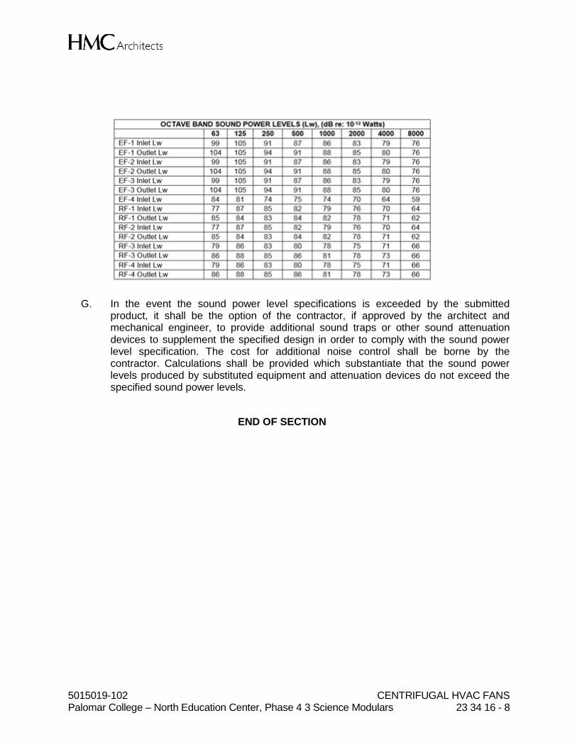
5015019-102 CENTRIFUGAL HVAC FANS Palomar College – North Education Center, Phase 4 3 Science Modulars 23 34 16 - 8
G. In the event the sound power level specifications is exceeded by the submitted product, it shall be the option of the contractor, if approved by the architect and mechanical engineer, to provide additional sound traps or other sound attenuation devices to supplement the specified design in order to comply with the sound power level specification. The cost for additional noise control shall be borne by the contractor. Calculations shall be provided which substantiate that the sound power levels produced by substituted equipment and attenuation devices do not exceed the specified sound power levels.
END OF SECTION

5015019-102 DIFFUSERS, REGISTERS, AND GRILLES Palomar College – North Education Center, Phase 4 3 Science Modulars 23 37 13 - 1
SECTION 23 37 13
DIFFUSERS, REGISTERS, AND GRILLES
PART 1 - GENERAL
1.01 RELATED DOCUMENTS
A. Drawings and general provisions of the Contract, including General and Supplementary Conditions and Division 01 Specification Sections, apply to this Section.
1.02 SUMMARY
A. Section Includes: 1. Round ceiling diffusers. 2. Radial diffusers 3. Perforated diffusers. 4. Linear slot diffusers. 5. Continuous tubular diffusers. 6. Adjustable bar registers and grilles. 7. Security grilles
B. Note that the diffuser schedule on the mechanical plans covers the various sizes and types of diffusers. Contractor shall coordinate these with the architectural ceiling plan for mounting borders to the correct ceiling types (i.e. “CSP-1” could apply to both T-Bar lay-in and surface mount in hard-lid ceiling areas).
C. Related Sections: 1. Section 233300 "Air Duct Accessories" for fire and smoke dampers and volume-
control dampers not integral to diffusers, registers, and grilles.
1.03 ACTION SUBMITTALS
A. Product Data: For each type of product indicated, include the following: 1. Data Sheet: Indicate materials of construction, finish, and mounting details; and
performance data including throw and drop, static-pressure drop, and noise ratings.
2. Diffuser, Register, and Grille Schedule: Indicate drawing designation, room location, quantity, model number, size, and accessories furnished.
B. Samples for Initial Selection: For diffusers, registers, and grilles with factory-applied color finishes.
C. Samples for Verification: For diffusers, registers, and grilles, in manufacturer's standard sizes to verify color selected.

5015019-102 DIFFUSERS, REGISTERS, AND GRILLES Palomar College – North Education Center, Phase 4 3 Science Modulars 23 37 13 - 2
1.04 INFORMATIONAL SUBMITTALS
A. Coordination Drawings: Reflected ceiling plans, drawn to scale, on which the following items are shown and coordinated with each other, using input from Installers of the items involved: 1. Ceiling suspension assembly members. 2. Method of attaching hangers to building structure. 3. Size and location of initial access modules for acoustical tile. 4. Ceiling-mounted items including lighting fixtures, diffusers, grilles, speakers,
sprinklers, access panels, and special moldings. 5. Duct access panels.
B. Source quality-control reports.
PART 2 - PRODUCTS
2.01 CEILING DIFFUSERS
A. Round Ceiling Diffuser (CSC-1, CSC-2, CSC-3) 1. Manufacturers shall be Price RCD, Titus, or Krueger. 2. Devices shall be specifically designed for variable-air-volume flows. 3. Material: Steel. 4. Finish: Baked enamel, color selected by Architect. 5. Face Style: Four, Three or Two cone. 6. Mounting: Duct connection.
B. Radial (Laminar) Ceiling Diffusers (CSR-1, CSR-2): 1. Manufacturers shall be Price RFD, Titus, or Krueger. 2. Devices shall be specifically designed for variable-air-volume flows. 3. Material: Aluminum. 4. Finish: Baked enamel, color selected by Architect. 5. Face Size: 24 by 24 inches or 24 by 48 inches (Refer to floor plans)
6. Face Style: Radial 7. Mounting: T-bar. 8. Pattern: Radial Laminar
C. Perforated Supply/Return/Exhaust (CSP-1, CSP-2, CSP-3, CSP-4) 1. Manufacturers shall be Price PDSP, Titus, or Krueger. 2. Diffuser shall be perforated face type ceiling diffuser. Diffuser shall have a
perforated face with 3/16-inch diameter holes on ¼-inch staggered centers and no less than 51 percent free area.
3. Devices shall be specifically designed for variable-air-volume flows. 4. Material: Steel backpan and pattern controllers, with aluminum face. 5. Finish: Baked enamel, color selected by Architect 6. Face Size: As indicated on plans. 7. Duct Inlet: As indicated on plans. 8. Mounting: Surface or T-bar, coordinate with architectural ceiling plans.
D. Perforated Return/Exhaust (CRP-1, CRP-2, CEP-1 through CEP-5) 1. Manufacturers shall be Price PDDR, Titus, or Krueger.

5015019-102 DIFFUSERS, REGISTERS, AND GRILLES Palomar College – North Education Center, Phase 4 3 Science Modulars 23 37 13 - 3
2. Diffuser shall be perforated face type ceiling diffuser. Diffuser shall have a perforated face with 3/16-inch diameter holes on ¼-inch staggered centers and no less than 51 percent free area.
3. Devices shall be specifically designed for variable-air-volume flows. 4. Material: Steel backpan and pattern controllers, with aluminum face. 5. Finish: Baked enamel, color selected by Architect 6. Face Size: As indicated on plans. 7. Duct Inlet: As indicated on plans. 8. Mounting: Surface or T-bar, coordinate with architectural ceiling plans.
2.02 CEILING LINEAR SLOT OUTLETS
A. Linear Slot Diffuser (LS-1, LS-2, LS-3, LS-4): 1. Manufacturers shall be Price JS (210 and 215) and Price AS220, Titus, or
Krueger. 2. Devices shall be specifically designed for variable-air-volume flows. 3. Border: Type 22 (Concealed) 4. Material - Shell: Aluminum 5. Material - Pattern Controller and Tees: Aluminum. 6. Finish - Face and Shell: Baked enamel, black 7. Finish - Pattern Controller: Baked enamel, black 8. Finish - Tees: Baked enamel, color selected by Architect. 9. Slot Width: Varies, refer to diffuser/register/grille schedule. 10. Number of Slots: One. 11. Length: Varies, refer to floor plans and diffuser/register/grille schedule. 12. Accessories: Insulated engineer plenum attachment, Single layer pattern
controller, adjust to horizontal airflow.
2.03 REGISTERS AND GRILLES
A. Adjustable Bar Register: 1. Manufacturers shall be Price 510Z, Titus, or Krueger. 2. Material: Steel. 3. Finish: Baked enamel, white color. 4. Face Blade Arrangement: Vertical, spaced 3/4 inch apart. 5. Core Construction: Removable. 6. Rear-Blade Arrangement: Horizontal, spaced 3/4 inch apart. 7. Frame: Flange, 1-1/4 inches wide. 8. Mounting: Countersunk screw. 9. Accessories:
a. Rear blade gang operator.
B. Security Grille (EG-5) 1. Manufacturers shall be Price 730H, Titus, or Krueger. 2. Application: Ducted exhaust from downdraft tables 3. Material: 304 Stainless Steel 4. Face Arrangement:
a. Shape: Square b. Design: Fixed bar c. Deflection: Zero degrees.
5015019-102 DIFFUSERS, REGISTERS, AND GRILLES Palomar College – North Education Center, Phase 4 3 Science Modulars 23 37 13 - 4
2.04 SOURCE QUALITY CONTROL
A. Verification of Performance: Rate diffusers, registers, and grilles according to ASHRAE 70, "Method of Testing for Rating the Performance of Air Outlets and Inlets."
PART 3 - EXECUTION
3.01 EXAMINATION
A. Examine areas where diffusers, registers, and grilles are to be installed for compliance with requirements for installation tolerances and other conditions affecting performance of equipment.
B. Proceed with installation only after unsatisfactory conditions have been corrected.
3.02 INSTALLATION
A. Install diffusers, registers, and grilles level and plumb.
B. Ceiling-Mounted Outlets and Inlets: Drawings indicate general arrangement of ducts, fittings, and accessories. Air outlet and inlet locations have been indicated to achieve design requirements for air volume, noise criteria, airflow pattern, throw, and pressure drop. Make final locations where indicated, as much as practical. For units installed in lay-in ceiling panels, locate units in the center of panel. Where architectural features or other items conflict with installation, notify Architect for a determination of final location.
C. Install diffusers, registers, and grilles with airtight connections to ducts and to allow service and maintenance of dampers, air extractors, and fire dampers.
3.03 ADJUSTING
A. After installation, adjust diffusers, registers, and grilles to air patterns indicated, or as directed, before starting air balancing.
END OF SECTION
5015019-102 DEDICATED OUTDOOR-AIR UNITS Palomar College – North Education Center, Phase 4 3 Science Modulars 23 74 33 - 1
SECTION 23 74 33
DEDICATED OUTDOOR-AIR UNITS
PART 1 - GENERAL
1.01 RELATED DOCUMENTS
A. Drawings and general provisions of the Contract, including General and Supplementary Conditions and Division 01 Specification Sections, apply to this Section.
1.02 SUMMARY
A. Section includes factory-packaged units capable of supplying up to 100 percent outdoor air and providing cooling only.
1.03 ACTION SUBMITTALS
A. The manufacturer, contractor, or supplier shall include a written statement that the submitted equipment, hardware, or accessory complies with the requirement of this particular specification section. 1. The manufacturer shall resubmit this specification section showing compliance
with each respective paragraph and specified items and features. 2. All exceptions shall be clearly identified by referencing respective paragraph and
other requirements along with proposed alternative. 3. Individual or partial submittals are not acceptable and will be returned without
review.
B. Product Data: For each type of product. Include rated capacities, operating characteristics, and furnished specialties and accessories.
C. Shop Drawings: 1. Include plans, elevations, sections, and attachment details. 2. Include details of equipment assemblies. Indicate dimensions, weights, loads,
required clearances, method of field assembly, components, and location and size of each field connection.
3. Prepare the following by or under the supervision of a qualified professional engineer: a. Mounting Details: For securing to housekeeping pad. b. Include diagrams for power, signal, and control wiring.
D. Delegated-Design Submittal: For design of vibration isolation and seismic restraints, including analysis data signed and sealed by the qualified professional engineer responsible for their preparation. 1. Unit fabrication and assembly details. 2. Vibration Isolation Base Details: Detail fabrication including anchorages and
attachments to structure and to supported equipment. Include adjustable motor bases, rails, and frames for equipment mounting.
5015019-102 DEDICATED OUTDOOR-AIR UNITS Palomar College – North Education Center, Phase 4 3 Science Modulars 23 74 33 - 2
3. Design Calculations: a. Calculate requirements for selecting vibration isolators and seismic
restraints and for designing vibration isolation bases. b. Indicate compliance with "Performance Requirements" article.
1.04 INFORMATIONAL SUBMITTALS
A. Coordination Drawings: equipment pad mounting details, drawn to scale, on which the following items are shown and coordinated with each other, using input from installers of the items involved: 1. Size and location of unit-mounted rails and anchor points and methods for
anchoring units to equipment pad.
B. Seismic Qualification Certificates: For dedicated outdoor-air units, accessories, and components, from manufacturer. 1. Basis for Certification: Indicate whether withstand certification is based on actual
test of assembled components or on calculation. 2. Dimensioned Outline Drawings of Equipment Unit: Identify center of gravity and
locate and describe mounting and anchorage provisions. 3. Detailed description of equipment anchorage devices on which the certification is
based and their installation requirements.
C. Startup service reports.
D. Sample Warranty: For special warranty.
1.05 CLOSEOUT SUBMITTALS
A. Operation and Maintenance Data: For units to include in emergency, operation, and maintenance manuals.
1.06 MAINTENANCE MATERIAL SUBMITTALS
A. Furnish extra materials that match products installed and that are packaged with protective covering for storage and identified with labels describing contents. 1. Filters: One set for each unit.
1.07 WARRANTY
A. Special Warranty: Manufacturer agrees to replace components of units that fail in materials or workmanship within specified warranty period. 1. Warranty Period for Heat Exchangers: 3 years from date of Substantial
Completion.
PART 2 - PRODUCTS
2.01 MANUFACTURERS
A. Manufacturers: Subject to compliance with requirements, provide products by one of the following:

5015019-102 DEDICATED OUTDOOR-AIR UNITS Palomar College – North Education Center, Phase 4 3 Science Modulars 23 74 33 - 3
1. Haakon 2. Energy Labs 3. Climate Craft
2.02 PERFORMANCE REQUIREMENTS
A. General Fabrication Requirements: Comply with requirements in ASHRAE 62.1, Section 5 - "Systems and Equipment," and Section 7 - "Construction and System Start-up."
B. Delegated Design: Engage a qualified professional engineer, as defined in Section 014010 "Quality Requirements," to design vibration isolation and seismic restraints.
C. Seismic Performance: Units shall withstand the effects of earthquake motions determined according to ASCE/SEI 7. 1. The term "withstand" means "the unit will remain in place without separation of
any parts when subjected to the seismic forces specified and the unit will be fully operational after the seismic event."
D. Cabinet Thermal Performance: 1. Maximum Overall U-Value: Comply with requirements in ASHRAE/IESNA 90.1. 2. Include effects of metal-to-metal contact and thermal bridges in the calculations.
E. Cabinet Surface Condensation: 1. Cabinet shall have additional insulation and vapor seals to prevent condensation
on the interior and exterior of the cabinet. 2. Portions of cabinet located downstream from the cooling coil shall have a thermal
break at each thermal bridge between the exterior and interior casing to prevent condensation from occurring on the interior and exterior surfaces. The thermal break shall not compromise the structural integrity of the cabinet.
F. Maximum Cabinet Leakage: 0.5 percent of the total supply-air flow at a pressure rating equal to the fan shut-off pressure.
G. Cabinet Deflection Performance: 1. Walls and roof deflection shall be within 1/240 of the span at the design working
pressure equal to the fan shut-off pressure. Deflection limits shall be measured at any point on the surface.
2. Floor deflections shall be within 1/360 of the span considering the worst-case condition caused by the following: a. Service personnel. b. Internal components. c. Design working pressure defined for the walls and roof.
H. Electrical components, devices, and accessories: Listed and labeled as defined in NFPA 70, by a qualified testing agency, and marked for intended location and application.

5015019-102 DEDICATED OUTDOOR-AIR UNITS Palomar College – North Education Center, Phase 4 3 Science Modulars 23 74 33 - 4
I. All AHUs must fit within the space designed by the architect and design team. The AHU manufacturer shall pay all expenses of the design team necessary to modify the project layout to accommodate non-conforming equipment. Internal personnel and service access shall not be compromised to comply with this section.
J. Primte movers (fans) and the AHU shall comply with all of the following requirements: maximum combined kW input power, minimum combined prime mover performance (i.e. flow and pressure including any necessary external sound attenuators), maximum AHU sound level, minimum AHU personnel and service access, and minimum fan quality. 1. Maximum prime mover input power establishes the maximum allowed combined
electrical input, into the motors, for all AHU’s submitted. The electrical input is fan shaft power (BHP x 0.746) / motor efficiency (%). Motor efficiency shall be the efficiency values as listed in NEMA MG1, Table 12-12 for the specific motor submitted.
2. Note: motor efficiencies used for compliance shall be the guaranteed minimum efficiency and not nominal motor efficiency.
3. Prime mover solutions using “lower” efficiency fans and/or motors must take additional steps to reduce ISP (increased coil face area, etc.) in order to comply with the maximum prime mover input power.
4. Maximum filter loading allowance shall be 0.75 in. w.c.
K. Maximum AHU sound power levels are as specified below. The discharge and inlet values listed below apply at the respective opening in the AHU based on the size and location of the opening. The submittal shall separate baseline fan sound power levels and internal air tunnel sound reductions. The design team reserves the right to require the AHU supplier to substantiate and verify all claims made regarding sound attenuation of the AHU construction and components. Third party test results of the proposed configuration at design flow and pressure shown on the mechanical drawings are the preferred method for validation. 1. If the submitted sound levels are more than 3 dB in any octave band above the
specified levels, then the supplier will be required to include additional sound treatment to reach the maximum sound levels shown below.
2. If duct-mounted sound attenuators external to the AHU are proposed to meet overall acoustic requirements, then the calculated pressure drop to be used for maximum energy input calculations shall include the added pressure drop of the attenuator and all necessary added ductwork and fittings required to accommodate the field installation of these attenuators.
3. If external sound attenuators are required to meet the acoustic performance shown below, then the location and clearances for these attenuators shall be coordinated with the architect and all other trades. Sound calculations shall be submitted ensuring that noise levels in occupied spaces adjacent to the external attenuator location are within specified levels.
Unit Location
Sound Power Levels [dB]
Band 1 2 3 4 5 6 7 8
Freq. 63 125 250 500 1000 2000 4000 8000
AHU-1 SA Discharge 76 73 75 74 72 69 65 57

5015019-102 DEDICATED OUTDOOR-AIR UNITS Palomar College – North Education Center, Phase 4 3 Science Modulars 23 74 33 - 5
Inlet 80 84 90 83 78 78 76 72
Radiated 65 66 55 50 50 50 50 50
AHU-2
SA Discharge 78 77 80 79 78 75 72 63
Inlet 82 76 85 76 74 76 76 71
Radiated 67 65 59 50 50 50 50 50
L. Capacities and Characteristics for AHU-1: 1. Supply Airflow: 31,670 CFM 2. External Static Pressure: 1.75 in. w.c. 3. Supply Fans:
a. Quantity: four b. Fan Class: II c. Speed: 1,339 RPM d. Brake Horsepower: 5.3 BHP per fan
4. Supply Fan Motors: a. Quantity: four b. Size: 7.5 HP per fan c. Speed: 1,150 RPM d. Volts: 460 e. Phase: Three f. Hertz: 60
5. Chilled-Water Cooling Coil: a. Fluid: Chilled water b. Sensible Heat-Transfer Rate: 1,381 MBH c. Total Heat-Transfer Rate: 1,607 MBH d. Entering-Air, Dry-Bulb Temperature: 95.0 deg F e. Entering-Air, Wet-Bulb Temperature: 70.0 deg F f. Leaving-Air, Dry-Bulb Temperature: 55.1 deg F g. Leaving-Air, Wet-Bulb Temperature: 53.7 deg F h. Face Area: 96 sq. ft.
i. Maximum Face Velocity: 330 FPM. j. Maximum Air-Side, Static-Pressure Drop: 0.34 in. w.c. k. Coil Type: Cleanable l. Piping Connections: Flanged, same end of coil m. Tube Thickness: 0.025 inch minimum thickness n. Fin Spacing: 10 FPI o. Fin Thickness: 0.0075 inch p. Number of Rows: 8 rows q. Coil Working-Pressure Ratings: 200 psig, 325 deg F
r. Fluid Flow: 132 GPM s. Maximum Fluid-Pressure Drop: 2.5 feet of head t. Entering-Fluid Temperature: 42.0 deg F u. Leaving-Fluid Temperature: 66.3 deg F
M. Capacities and Characteristics for AHU-2: 1. Supply Airflow: 75,710 CFM 2. External Static Pressure: 2.75 in. w.c. 3. Supply Fans:

5015019-102 DEDICATED OUTDOOR-AIR UNITS Palomar College – North Education Center, Phase 4 3 Science Modulars 23 74 33 - 6
a. Quantity: eight b. Fan Class: II c. Speed: 1,556 RPM d. Brake Horsepower: 8.5 BHP per fan
4. Supply Fan Motors: a. Quantity: eight b. Size: 10 HP per fan c. Speed: 1,150 d. Volts: 460 e. Phase: Three f. Hertz: 60
5. Chilled-Water Cooling Coil: a. Fluid: Chilled water b. Sensible Heat-Transfer Rate: 3,381 MBH c. Total Heat-Transfer Rate: 4,040 MBH d. Entering-Air, Dry-Bulb Temperature: 95.0 deg F e. Entering-Air, Wet-Bulb Temperature: 70.0 deg F f. Leaving-Air, Dry-Bulb Temperature: 54.1 deg F g. Leaving-Air, Wet-Bulb Temperature: 52.8 deg F h. Face Area: 221 sq. ft.
i. Maximum Face Velocity: 343 FPM. j. Maximum Air-Side, Static-Pressure Drop: 0.36 in. w.c. k. Coil Type: Cleanable l. Piping Connections: Flanged, same end of coil m. Tube Thickness: 0.025 inch minimum thickness n. Fin Spacing: 10 FPI o. Fin Thickness: 0.0075 inch p. Number of Rows: 8 rows q. Coil Working-Pressure Ratings: 200 psig, 325 deg F
r. Fluid Flow: 316 GPM s. Maximum Fluid-Pressure Drop: 6.1 feet of head t. Entering-Fluid Temperature: 42.0 deg F u. Leaving-Fluid Temperature: 67.6 deg F
2.03 CABINET
A. Construction: Double wall.
B. Exterior Casing Material: Galvanized steel with paint finish. Unit shall be finished painted with two components, etch bond primer and finish painted with grey enamel. All metal surfaces shall be pre-painted with vinyl wash primer to ensure paint bonds to metal.
C. Interior Casing Material: Galvanized steel.
D. Walls and roofs shall be constructed of 16 gauge galvanized steel, 2” thick acoustic thermal panels. The inner liner shall be 22 gauge solid galvanized steel. Insulation shall be 2” thick 3 lbs density fiberglass. Insulation shall meet flame spread rating of less than 25 and a smoke developed rating of less than 50 when measured in
5015019-102 DEDICATED OUTDOOR-AIR UNITS Palomar College – North Education Center, Phase 4 3 Science Modulars 23 74 33 - 7
accordance with ASTM E84. All permanently joined flanged panel surfaces shall be sealed with an individual strip of 1/8” x 3/8” tape sealer. Tape sealer shall be LEED qualified. Wall seams shall be turned inward to provide a clean flush exterior finish. All panel seams shall be sealed during assembly to produce an airtight seal.
E. Access Doors: Access doors shall be manufactured from 16 gauge galvanized steel. The doors shall be double wall construction with 22 gauge solid metal liner on the inside. Corners of the doors shall be continuously welded for rigidity. Two inch 3 lb/cu ft. density insulation shall be sandwiched between the 16 gauge outer layer and the 22 gauge inner layer. Doors must be the same thickness as the unit casing to maximize thermal and acoustical resistance. A 12” round hermetically sealed Double Glazed Laminated glass window shall be provided for each door. Hinges shall be continuous piano type stainless steel. 1. Two chrome plated “Ventlok” Model #310 high pressure latches operable from
either side of the door shall be provided. Door opening shall be fully gasketed with continuous ½” closed cell hollow round black gasket with a metal encapsulated reinforcing backing that mechanically fastens to the door frame. Door frames shall be made from 16 gauge galvanized steel with the outside side of the door flush with the unit. Minimum door opening size shall be 18” x 70” (where height permits). Fan compartments must have a door of minimum width to remove the motor.
2. All access doors must swing against the air pressure (i.e. positive pressure plenum doors must swing in).
F. Lifting and Handling Provisions: Factory-installed shipping skids and lifting lugs.
G. Base Rails: Structural steel C-channel iron around the perimeter of the unit, with intermediate channel and angle iron supports for mounting on equipment pad as indicated. Units less than or equal to 20’ long shall have a minimum 4” channel, and units greater than 20’ shall have a minimum 6” channel.
H. Access for Inspection, Cleaning, and Maintenance: Comply with requirements in ASHRAE 62.1. 1. Service Doors: Hinged access doors with gaskets. Material and construction of
doors shall match material and construction of cabinet in which doors are installed.
I. Roof: On indoor units, roof seams shall be turned inward to provide a clean flush exterior finish.
J. Floor: A 0.12” thick aluminum checker plate floor shall be installed on the base. Floor shall be flat reinforced from below, with all seams continuously welded. Drive screw attachment and caulking are not acceptable. Base shall be provided with lifting lugs, minimum four (4) per unit section. The base shall be insulated with 4” fiberglass insulation and sheeted with a 22 gauge galvanized steel liner. Floors that “oil can” are not acceptable. Provide a 1.5” perimeter collar around the entire unit, and around each floor opening to ensure the unit is internally watertight. The entire base shall act as an auxiliary drain pan and hold up to 1.5” of water.
K. Cabinet Insulation:
5015019-102 DEDICATED OUTDOOR-AIR UNITS Palomar College – North Education Center, Phase 4 3 Science Modulars 23 74 33 - 8
1. Type for all sections except for discharge plenum section: Fibrous-glass duct lining complying with ASTM C 1071, Type II
2. Type for discharge air plenum section: flexible elastomeric insulation complying with ASTM C 534, Type II, sheet materials.
3. Thickness: 2 inches. 4. Insulation Adhesive: Comply with ASTM C 916, Type I. 5. Mechanical Fasteners: Suitable for adhesive, mechanical, or welding attachment
to casing without damaging liner and without causing air leakage when applied as recommended by manufacturer.
L. Condensate Drain Pans: 1. Shape: Rectangular, with 2 percent slope in at least two planes to direct water
toward drain connection. 2. Size: Large enough to collect condensate from cooling coils including coil piping
connections, coil headers, and return bends. a. Length: Extend drain pan downstream from leaving face to comply with
ASHRAE 62.1. b. Depth: A minimum of 2 inches deep.
3. Configuration: Double wall, with space between walls filled with foam insulation and moisture-tight seal.
4. Material: Continuously welded 316 Stainless-steel sheets. 5. Drain Connection:
a. Located on one end of pan, at lowest point of pan. b. Terminated with threaded nipple. c. Minimum Connection Size: NPS 2.
6. Units with stacked coils shall have an intermediate drain pan to collect condensate from top coil and shall be interconnected with 1” drain lines.
M. Surfaces in Contact with Airstream: Comply with requirements in ASHRAE 62.1 for resistance to mold and erosion.
2.04 SUPPLY FAN
A. Basis of design for specific purpose plenum fans is the AcoustiFLO Modular Fan. Each fan assembly shall be complete with motor, single width single inlet (SWSI) centrifugal fan wheel, and inlet cone. 1. Aerodynamic performance of each fan (flow, pressure, and BHP) shall be
traceable to the AMCA Certified Ratings Program. For fans certified within a defined enclosure (module, box, cell, or cube) compliance with this section is complete provided that the enclosure of the proposed fan is identical to the certified product. For fans that are not rated or certified within a defined enclosure (often called bare wheels) there shall be a minimum of one wheel diameter between adjacent wheels (vertically and horizontally) and one-half wheel diameter from the periphery of each wheel to the air tunnel roof, floor, and walls of that air tunnel.
2. Acoustic performance of each fan shall be traceable to AMCA Certified Ratings Program. For fans certified within a defined enclosure (module, box, cell, or cube) compliance with this section is complete provided that the enclosure of the

5015019-102 DEDICATED OUTDOOR-AIR UNITS Palomar College – North Education Center, Phase 4 3 Science Modulars 23 74 33 - 9
proposed fan is identical to the certified product. For fans that are not rated or certified within a defined enclosure the supplier has two options: a. Submit third party test data that validates the performance of the proposed
quantity, using the proposed wheel size and configuration. b. Add 6 dB, in all eight octave bands, to any acoustic prediction related to
that AHU. 3. A pressure summary shall be included in the submittal to identify respective
pressure tabulations including, but not limited to, outlet effect within the discharge section, coils, filters clean, filters loaded (clean and dirty ratings required), dampers, inlet effect within the cabinet, louvers, sound attenuators, and system effects.
4. At design flow and design pressure the selection point shall not exceed 90% of the peak static pressure available from the fan at design operating speed. All VAV/VFD fans shall be stable down to 35% of design air flow. Minimum pressure at zero flow shall be assumed as one (1) inch or as required per ASHRAE 90.1.
5. For any fan section containing more than one fan, provide hardware that minimizes reverse flow in the event that a fan/motor/VFD failure or fault. The pressure loss through the isolation device shall be identified as the line item in the static pressure summary. Provide test data showing the acoustic effect of the backflow device on the acoustic performance of the fan.
B. Plenum Fan Type: Single width, non-overloading, with airfoil blades. 1. Fan Wheel Material: Aluminum; welded directly to motor shaft. 2. Fan Wheel Drive and Arrangement: Direct drive, AMCA Arrangement 4. 3. Fan panel and frame Material: Powder-coated steel, stainless steel, or aluminum. 4. The fan shall be sized such that the motor operating speed does not exceed
ninety (90) hertz output frequency from the variable frequency drive (VFD). There shall be one (1) VFD per motor.
5. Fan isolation: Provide 1.0 inch internal spring isolation of the fan, motor, and diffuser assembly. As an alternative, mount the fan and motor on an internal, fully-welded, rigid base. Base shall be free-floating at all four corners on spring type isolators with earthquake restraints. The fan assembly shall be isolated from the cabinet by steel springs with minimum deflection of 2.0 inches. The spring isolators shall be mounted to structural steel members. All isolators shall be rated for zone 4 seismic requirements. The spring isolators shall be mounted on a waffle pad for vibration isolator. Non-isolated fans will not be accepted.
6. Fan Enclosure: Easily removable enclosure with OSHA safety screen around rotating parts.
7. Fan Balance: Each fan assembly shall be balanced to AMCA/ANSI 204, balance / vibration grade three (BV-3). In addition, vibratory force at the point of interface between the fan and support structure shall not exceed 10 micro-G. This measurement shall be made on each fan prior to installation in the AHU. Measurements shall be submitted prior to shipment of the AHU. A copy of the above balance test data for this project showing calculations for deflection and critical speed of the shaft and wheel assembly shall be submitted to the engineer and a copy forwarded to the owner.
8. Bearings shall be rated for 200,000 hour AFBMA L50 bearing life (or 50,000 L10 life). Grease ports for bearings shall be extended to accessible locations at the

5015019-102 DEDICATED OUTDOOR-AIR UNITS Palomar College – North Education Center, Phase 4 3 Science Modulars 23 74 33 - 10
exterior of the air handling unit with labels clearly indicating the location and purpose of the grease ports.
9. Acceptable sound absorbing media shall be slag wool, UltraTouch®, or melamine foam. All sound absorbing media shall be encapsulated. Acceptable forms of encapsulation shall be Mylar, Tedlar, or Typar. Perforated metal is not recognized as a method of encapsulation. If fiberglass is proposed, then it must be encapsulated behind two separate layers of an approved encapsulation media and must be certified to contain no formaldehyde.
10. Each fan assembly shall have a flow/pressure/speed test prior to installation in the AHU. Test results shall be submitted prior to shipment of the AHU.
C. Motors: 1. Comply with NEMA designation, temperature rating, service factor, and efficiency
requirements for motors specified in Section 230513 "Common Motor Requirements for HVAC Equipment."
2. Enclosure: Totally enclosed fan-cooled (TEFC). 3. Efficiency: Premium efficient. 4. Service Factor: 1.15. 5. Motor bearings shall have a minimum L-10 life of 200,000 hours. 6. Accessories: Provide motor shaft grounding for all motors connected VFDs. 7. Provide I-beam hoist rail above fan section access doors to facilitate removal of
motors.
2.05 COOLING COILS
A. Capacity Ratings: Comply with ASHRAE 33 and ARI 410
B. Coil Casing Material: 16 gauge 316 stainless steel
C. Tube Material: Copper. Construct tubes of 5/8 inch O.D. minimum 0.025 and 0.030 bends inch thick copper.
D. Tube Header Material: Copper
E. Fin Material: Copper. 0.0075 inch thick.
F. Fin and Tube Joints: Mechanical bond.
G. Leak Test: Coils shall be leak tested with air underwater.
H. Coils shall be fully enclosed within casing and cooling coils shall be on mounted 304 stainless steel angle racks manufactured to allow coils to slide out individually.
I. Removable coil access panels shall be provided to remove coils through casing wall. Coils shall be individually removable from the access side. Coils must be individually racked, removable through the side access panels.
5015019-102 DEDICATED OUTDOOR-AIR UNITS Palomar College – North Education Center, Phase 4 3 Science Modulars 23 74 33 - 11
2.06 FILTERS
A. All air filters shall be State Fire Marshal approved and listed type. Preformed filters having combustible framing shall be tested as a complete assembly. Air filters in all occupancies shall be Class 2 or better, as shown in the State Fire Marshal listing. Air filters shall be accessible for replacement.
B. Disposable Panel Filters (Pre-Filters): Start-up only. 1. Comply with NFPA 90A. 2. Factory-fabricated, viscous-coated, flat-panel type. 3. Thickness: 2 inches 4. Initial Resistance: 0.4 in. w.c. 5. Recommended Final Resistance: 0.75 in. w.c. 6. Minimum Merv: 8, according to ASHRAE 52.2. 7. Media: Interlaced glass fibers sprayed with nonflammable adhesive.
C. Extended-Surface, Disposable Panel Filters (Final Filters): 1. Comply with NFPA 90A. 2. Factory-fabricated, dry, extended-surface type. 3. Thickness: 12 inches. 4. Initial Resistance: 0.4 in. w.c. 5. Recommended Final Resistance: 0.75 in. w.c. 6. Minimum Merv: 13, according to ASHRAE 52.2. 7. Media: Fibrous material formed into deep-V-shaped pleats with antimicrobial
agent and held by self-supporting wire grid.
D. Mounting Frames: 1. Panel filters arranged for flat or angular orientation, with access doors on both
sides of unit. Filters shall be removable from one side or from access plenum. 2. Extended surface filters arranged for flat orientation, removable from access
plenum. 3. Stainless steel with gaskets and fasteners, suitable for bolting together into built-
up filter banks with space for pre-filter.
2.07 ELECTRICAL POWER CONNECTIONS
A. General Electrical Power Connection Requirements: Factory-installed and -wired switches, motor controllers, transformers, and other necessary electrical devices shall provide a single-point field power connection to unit.
B. All wiring shall be performed in a UL 508 listed shop. Provide single source power panels (SSPP’s) that are constructed according to CEC regulations and carry a U.L. 508 listing and label. The panel shall include a non-fused main disconnect switch covering all fans in each unit, VFDs’s for variable volume units, and any necessary transformers, Hand-Off-Auto switches, relays and pilot lights for complete operation of the fans in the unit. The single source power panels shall be factory wired to all factory furnished devices such as motors and interlocks.
5015019-102 DEDICATED OUTDOOR-AIR UNITS Palomar College – North Education Center, Phase 4 3 Science Modulars 23 74 33 - 12
C. The air handling unit manufacturer, for the purpose of sole source responsibility, shall manufacture all electrical panel assemblies supplied for the air handlers. The air handling unit manufacturer shall be a U.L. 508 listed panel shop.
D. Enclosure: NEMA 250, Type 4, mounted in unit with hinged access door in unit cabinet having a lock and key or padlock and key,
E. Wiring: Numbered and color-coded to match wiring diagram.
F. All wiring shall be run in corrosion resistant conduit. Exception: flexible when connecting to a motor. Raceways are not acceptable.
G. Power Interface: Field power interface shall be to NEMA KS 1, heavy-duty, nonfused disconnect switch.
H. Factory Wiring: Branch power circuit to each motor and to controls with one of the following disconnecting means: 1. NEMA KS 1, heavy-duty, fusible switch with rejection-type fuse clips rated for
fuses. Select and size fuses to provide Type 2 protection according to IEC 60947-4-1.
2. NEMA KS 1, heavy-duty, nonfusible switch. 3. UL 489, motor-circuit protector (circuit breaker) with field-adjustable, short-circuit
trip coordinated with motor locked-rotor amperes.
I. Factory-Mounted, Overcurrent-Protection Service: For each motor.
J. Transformer: Factory mounted with primary and secondary fuses and sized with enough capacity to operate electrical load plus spare capacity.
K. Controls: Factory wire unit-mounted controls where indicated.
L. Lights: Factory wire unit-mounted lights.
M. Receptacle: Factory wire unit-mounted, ground fault interrupt (GFI) duplex receptacle.
N. Control Relays: Auxiliary and adjustable time-delay relays.
2.08 CONTROLS
A. Control equipment and sequence of operation are specified in Section 230923 "Direct Digital Control (DDC) System for HVAC" and Section 230993 "Sequence of Operations for HVAC DDC."
B. AHU manufacturer shall provide controls-ready construction with conduit and j-boxes installed in all sections to eliminate any unit penetrations in the field. All conduit and j-boxes shall be painted to match the rest of the interior coatings.
C. All controls shall be field installed by the installing temperature controls contractor and coordinated with the building automation system. These controls shall include all

5015019-102 DEDICATED OUTDOOR-AIR UNITS Palomar College – North Education Center, Phase 4 3 Science Modulars 23 74 33 - 13
damper actuators, temperature sensors, pressure sensors, filter differential pressure sensors, smoke, and fire detectors as indicated on the control drawings.
D. Electric and electronic controls shall be wired to a terminal block in a sheet metal enclosure located at a common location mounted on the air handling unit. All pressure sensing controls shall be piped to a common point on the unit with ¼” compression fittings.
E. Wiring for chilled water control valves shall be field supplied by the installing contractor. Control valve wiring shall be extended to an external junction box located near the coil connections with the final wiring connection done by the temperature controls contractor. All control valves and piping specialties shall be provided by the temperature controls contractor and/or piping contractor.
F. If the unit required splitting, junction boxes shall be furnished on each section to allow the control contractor to make final connections in the field. Wiring shall be clearly labeled to allow ease in final interconnections.
G. All controls shall be supplied and installed by the Division 230923 Direct Digital Controls for HVAC controls contractor. All wiring shall be performed in a U.L. 508 listed shop.
H. Electrical contractor shall bring separate 120/1/60 power for controls.
I. Unit-Mounted Status Panel: 1. Provide factory installed Dwyer Series 2000 Magnehelic Pressure Gauge or
Engineer approved equal to measure differential pressure across the MERV 13 filter bank. a. Gauge shall be complete with static pressure tips, hardware, and fittings.
J. Control Dampers: 1. Damper Location: Factory installed inside unit for ease of blade axle and bushing
service. Arrange dampers located in a mixing box to achieve convergent airflow to minimize stratification.
2. Damper Leakage: Comply with requirements in AMCA 500-D. Leakage shall not exceed 6.5 cfm per sq. ft. at a static-pressure differential of 4.0 inches water column when a torque of 5 inch pounds per sq. ft. is applied to the damper jackshaft.
3. Damper Rating: Rated for close-off pressure equal to the fan shutoff pressure. 4. Damper Label: Bear the AMCA seal for both air leakage and performance. 5. Blade Configuration: Unless otherwise indicated, use parallel blade configuration
for two-position control and equipment isolation service. 6. Damper Frame Material: Extruded aluminum. 7. Blade Type: Hollow-shaped airfoil. 8. Blade Material: Extruded aluminum. 9. Maximum Blade Width: 6 inches. 10. Maximum Blade Length: 48 inches. 11. Blade Seals: Replaceable, continuous perimeter vinyl seals and jambs with
stainless-steel compression-type seals. 12. Bearings: Thrust bearings for vertical blade axles.

5015019-102 DEDICATED OUTDOOR-AIR UNITS Palomar College – North Education Center, Phase 4 3 Science Modulars 23 74 33 - 14
2.09 ACCESSORIES
A. Service Lights and Switch: Factory installed in each accessible section with weatherproof cover. Factory wire lights to a single-point field connection.
B. Duplex Receptacle: Factory mounted in unit supply-fan section with 20 amp 120 V GFI duplex receptacle and weatherproof cover.
C. ROLLING FILTER LADDER (AHU-2): Filter banks shall be provided with an integral rolling filter ladder. The ladder shall be all welded steel construction with abrasive treads which are at least 5 inches deep and 14 inches wide. The ladder is provided with a smooth rolling steel upper track which is 0.94” diameter fixed to the filter rack. The ladder has wheels on the floor which allow movement of the track across the width of the filter rack. The wheels are provided with a brake which prevents movement during use. When in use, the ladder is positioned at an 80 degree climbing angle. The ladder can be positioned in a vertical position when not in use.
D. ACCESS PLATFORM (AHU-2): Unit shall be provided with an integral cantilevered platform built into the upper deck of the unit. The platform shall be designed to carry a live concentrated load of 400 lbs and require no post to support it. 1. The floor of the platform shall be fully welded 0.12” thick aluminum checker plate. 2. Platform shall be a minimum 54” wide or wider to accommodate required
electrical door swing clearances. 3. The Platform shall be provided with a perimeter railing meeting OSHA industrial
standards. A toe kick shall be provided. The railing shall be manufactured with round galvanized tubes.
4. The ladder shall be suspended from the platform and be provided with integral hand rails at the platform level. The ladder shall be supported from below on site at the same level as the bottom of the AHU base rail. The ladder will ship loose for site reinstallation by others.
E. RUSKIN PRD18 Pressure Relief Doors as indicated on drawings.
PART 3 - EXECUTION
3.01 EXAMINATION
A. Examine substrates, areas, and conditions, with Installer present, for compliance with requirements for installation tolerances and other conditions affecting performance of the Work.
B. Examine roughing-in for piping, ducts, and electrical systems to verify actual locations of connections before equipment installation.
C. Examine roof curbs and equipment supports for suitable conditions where units will be installed.
D. Proceed with installation only after unsatisfactory conditions have been corrected.

5015019-102 DEDICATED OUTDOOR-AIR UNITS Palomar College – North Education Center, Phase 4 3 Science Modulars 23 74 33 - 15
3.02 INSTALLATION
A. Comply with manufacturer's rigging and installation instructions for unloading units and moving to final locations.
B. Equipment Mounting: 1. Install air units on cast-in-place concrete equipment bases. Comply with
requirements for equipment bases and foundations specified by the Structural Engineer of Record.
2. Comply with requirements for vibration isolation and seismic control devices specified in Section 230548 "Vibration and Seismic Controls for HVAC."
3. Comply with requirements for vibration isolation devices specified in Section 230548 "Vibration Controls for HVAC."
C. Install wall- and duct-mounted sensors furnished by manufacturer for field installation. Install control wiring and make final connections to control devices and unit control panel.
D. Install separate devices furnished by manufacturer and not factory installed.
E. Install new filters at completion of equipment installation and before testing, adjusting, and balancing.
F. Install drain pipes from unit drain pans to sanitary drain. 1. Drain Piping: Drawn-temper copper water tubing complying with ASTM B 88,
Type L, with soldered joints. 2. Pipe Size: Same size as condensate drain pan connection.
3.03 CONNECTIONS
A. Where installing piping adjacent to units, allow space for service and maintenance.
B. Hydronic Piping Connections: 1. Comply with requirements in Section 232113 "Hydronic Piping" and Section
232116 Hydronic Piping Specialties." 2. Install shutoff valve and union or flange on each supply connection and install
balancing valve and union or flange on each return connection.
C. Duct Connections: 1. Comply with requirements in Section 233113 "Metal Ducts." 2. Drawings indicate the general arrangement of ducts. 3. Connect ducts to units with flexible duct connectors. Comply with requirements
for flexible duct connectors in Section 233300 "Air Duct Accessories."
D. Electrical Connections: Comply with requirements for power wiring, switches, and motor controls in electrical Sections. 1. Install electrical devices furnished by unit manufacturer but not factory mounted.

5015019-102 DEDICATED OUTDOOR-AIR UNITS Palomar College – North Education Center, Phase 4 3 Science Modulars 23 74 33 - 16
3.04 STARTUP SERVICE
A. Engage a factory-authorized service representative to perform startup service. 1. Complete installation and startup checks according to manufacturer's written
instructions. 2. Inspect units for visible damage to furnace combustion chamber. 3. Inspect casing insulation for integrity, moisture content, and adhesion. 4. Verify that clearances have been provided for servicing. 5. Verify that controls are connected and operable. 6. Verify that filters are installed. 7. Clean coils and inspect for construction debris. 8. Inspect and adjust vibration isolators and seismic restraints. 9. Verify bearing lubrication. 10. Clean fans and inspect fan-wheel rotation for movement in correct direction
without vibration and binding. 11. Adjust fan belts to proper alignment and tension. 12. Start unit. 13. Inspect and record performance of interlocks and protective devices including
response to smoke detectors by fan controls and fire alarm. 14. Operate unit for run-in period. 15. Calibrate controls. 16. Adjust and inspect high-temperature limits. 17. Inspect supply fan isolation dampers for proper stroke 18. Verify operational sequence of controls. 19. Measure and record the following airflows. Plot fan volumes on fan curve.
a. Supply-air volume.
B. After startup, change filters, verify bearing lubrication, and adjust belt tension.
C. Remove and replace components that do not properly operate and repeat startup procedures as specified above.
D. Prepare written report of the results of startup services.
3.05 ADJUSTING
A. Adjust initial temperature and humidity set points.
B. Set field-adjustable switches and circuit-breaker trip ranges as indicated.
C. Occupancy Adjustments: When requested within 12 months from date of Substantial Completion, provide on-site assistance in adjusting system to suit actual occupied conditions. Provide up to two visits to Project during other-than-normal occupancy hours for this purpose.
3.06 DEMONSTRATION
A. Engage a factory-authorized service representative to train Owner's maintenance personnel to adjust, operate, and maintain units.

5015019-102 DEDICATED OUTDOOR-AIR UNITS Palomar College – North Education Center, Phase 4 3 Science Modulars 23 74 33 - 17
END OF SECTION
5015019-102 ELECTRICAL GENERAL PROVISIONS Palomar College - North Education Center, Phase 4 Science Modulars 26 01 00 - 1 ©JCE #17057.04
SECTION 26 01 00
ELECTRICAL GENERAL PROVISIONS ARTICLE 1 SUMMARY
1.1 This Division of the specification outlines the provisions of the contract work to be performed under this Division.
1.2 This Section applies to and forms a part of each section of specifications in
Division 26 and all work performed under the electrical and communications contracts.
1.3 In addition, work in this Division is governed by the provisions of the bidding
requirements, contract forms, general conditions and all sections under general requirements.
1.4 These specifications contain statements which may be more definitive or more
restrictive than those contained in the General Conditions. Where these statements occur, they shall take precedence over the General Conditions.
1.5 Where the words 'provide' or 'provision' are used, it shall be definitely interpreted
as 'furnishing and installing complete in operating condition'. Where the words 'as indicated' or 'as shown' are used, it shall mean as shown on contract drawings.
1.6 Where items are specified in the singular, this Division shall provide the quantity
as shown on drawings plus any spares or extras mentioned on drawings or specifications. All specified and supplied equipment shall be new.
ARTICLE 2 CONTRACTOR QUALIFICATIONS
2.1 The Contractor shall have a current California C-10 Electrical Contractor’s license and all individuals working on this project shall have passed the Department of Industrial Relations Division of apprenticeship Standards – “Electrician Certification Program.”
ARTICLE 3 CODES, PERMITS AND FEES
3.1 Comply with all applicable laws, ordinances, rules, regulations, codes, or rulings of governmental units having jurisdiction as well as standards of NFPA, and serving utility requirements.
3.2 Obtain permits, fees, inspections, meter and the like, associated with work in
each section of this Division.
3.3 Installation procedures, methods and conditions shall comply with the latest requirements of the Federal Occupational Safety and Health Act (OSHA).
5015019-102 ELECTRICAL GENERAL PROVISIONS Palomar College - North Education Center, Phase 4 Science Modulars 26 01 00 - 2 ©JCE #17057.04
ARTICLE 4 EXAMINATION OF PREMISES
4.1 Examine the construction drawings and premises prior to bidding. No allowances will be made for not being knowledgeable of existing conditions.
ARTICLE 5 STANDARDS
5.1 The following standard publications of the latest editions enforced and supplements thereto shall form a part of these specifications. All electrical work must, as a minimum, be in accordance with these standards.
5.1.1 2016 California Electrical Code (CEC), Part 3 Title 24 CCR. 5.1.2 National Fire Protection Association. 5.1.3 Underwriters' Laboratories, Inc. (UL). 5.1.4 Certified Ballast Manufacturers' Association (CBM). 5.1.5 National Electrical Manufacturers' Association (NEMA). 5.1.6 Institution of Electrical & Electronics Engineers (IEEE). 5.1.7 American Society for Testing & Materials (ASTM). 5.1.8 National Board of Fire Underwriters (NBFU). 5.1.9 National Board of Standards (NBS). 5.1.10 American National Standards Institute (ANSI). 5.1.11 Insulated Power Cable Engineers Association (IPECS). 5.1.12 Electrical Testing Laboratories (ETL). 5.1.13 National Electrical Safety Code (NESC). 5.1.14 2016 California Building Code (CBC), Part 2, Title 24 CCR. 5.1.15 2016 California Fire Code (CFC), Part 9, Title 24, CCR. 5.1.16 2016 NFPA 72 with California State Amendments 5.1.17 National Electrical Testing Association (NETA), 2010 or most current
ARTICLE 6 DEFINITIONS
6.1 Concealed: Hidden from sight, as in trenches, chases, hollow construction, or above furred spaces, hung ceilings - acoustical or plastic type, or exposed to view only in tunnels, attics, shafts, crawl spaces, unfinished spaces, or other areas solely for maintenance and repair.
6.2 Exposed, Non-Concealed, Unfinished Space: A room or space that is ordinarily
accessible only to building maintenance personnel, a room noted on the 'finish schedule' with exposed and unpainted construction for walls, floors, or ceilings or specifically mentioned as 'unfinished'.
6.3 Finish Space: Any space ordinarily visible, including exterior areas.
ARTICLE 7 WORK AND MATERIALS
7.1 Unless otherwise specified, all materials must be new and of the best quality. Materials previously incorporated into other projects, salvaged, or refurbished are not considered new. Perform all labor in a thorough and workmanlike manner.
5015019-102 ELECTRICAL GENERAL PROVISIONS Palomar College - North Education Center, Phase 4 Science Modulars 26 01 00 - 3 ©JCE #17057.04
7.2 All materials provided under the contract must bear the UL label where normally
available. Note that this requirement may be repeated under equipment specifications. In general, such devices as will void the label should be provided in separate enclosures and wired to the labeled unit in proper manner.
ARTICLE 8 SHOP DRAWINGS AND SUBMITTALS
8.1 Submit shop drawings and all data in accordance with Division 1 of these specifications and as noted below for all equipment provided under this Division.
8.2 Shop drawings submittals demonstrate to the Architect that the Contractor
understands the design concept. The Contractor demonstrates his understanding by indicating which equipment and material he intends to furnish and install and by detailing the fabrication and installation methods of material and equipment he intends to use. If deviations, discrepancies, or conflicts between submittals and specifications are discovered either prior to or after submittals are processed, notify the Architect immediately.
8.3 Manufacturer’s data and dimension sheets shall be submitted giving all pertinent
physical and engineering data including weights, cross sections and maintenance instructions. Standard items of equipment such as receptacles, switches, plates, etc., which are cataloged items, shall be listed by manufacturer.
8.4 Index all submittals and reference them to these specifications. All submittal
items shall be assembled and submitted, one for each specification section. (Multiple specification sections may be grouped together in one common submittal binder, as long as each individual section is clearly identified.) Partial or incomplete submittal sections will not be reviewed.
ARTICLE 9 EQUIPMENT PURCHASES
9.1 Arrange for purchase and delivery of all materials and equipment within 20 days after approval of submittals. All materials and equipment must be ordered in ample quantities for delivery at the proper time. If items are not on the project in time to expedite completion, the Owner may purchase said equipment and materials and deduct the cost from the contract sum.
9.2 Provide all materials of similar class or service by one manufacturer.
ARTICLE 10 COOPERATIVE WORK
10.1 Correct without charge any work requiring alteration due to lack of proper supervision or failure to make proper provision in time. Correct without charge any damage to adjacent work caused by the alteration.
10.2 Cooperative work includes: General supervision and responsibility for proper
location and size of work related to this Division, but provided under the other

5015019-102 ELECTRICAL GENERAL PROVISIONS Palomar College - North Education Center, Phase 4 Science Modulars 26 01 00 - 4 ©JCE #17057.04
sections of these specifications, and installation of sleeves, inserts, and anchor bolts for work under each section in this Division.
ARTICLE 11 VERIFICATION OF DIMENSIONS
11.1 Scaled and figured dimensions are approximate only. Before proceeding with work, carefully check and verify dimensions, etc., and be responsible for properly fitting equipment and materials together and to the structure in spaces provided.
11.2 Drawings are essentially diagrammatic, and many offsets, bends, pull boxes,
special fittings, and exact locations are not indicated. Carefully study drawings and premises in order to determine best methods, exact location, routes, building obstructions, etc. and install apparatus and equipment in manner and locations to avoid obstructions, preserve headroom, keep openings and passageways clear, and maintain proper clearances.
ARTICLE 12 CUTTING AND PATCHING
12.1 All cutting and patching shall be in accordance with Division 1 of these specifications and as noted below.
12.2 Cut existing work and patch as necessary to properly install new work. As the
work progresses, leave necessary openings, holes, chases, etc., in their correct location. If the required openings, holes, chases, etc., are not in their correct locations, make the necessary corrections at no cost to the Owner. Avoid excessive cutting and do not cut structural members including wall framing without the consent of the Architect.
ARTICLE 13 CLOSING-IN OF UNINSPECTED WORK
13.1 Cover no work until inspected, tested, and approved by the Architect. Where work is covered before inspection and test, uncover it and when inspected, tested, and approved, restore all work to original proper condition at no additional cost to Owner.
ARTICLE 14 EXCAVATION AND BACKFILL
14.1 All excavation and backfill shall be in accordance with Division 1 of these specifications and as noted below.
14.2 Perform all necessary excavation, shoring, and backfilling required for the proper
laying of all conduits inside the building and premises, and outside as may be necessary.
14.3 Excavate all trenches open cut, keep trench banks as nearly vertical as
practicable, and sheet and brace trenches where required for stability and safety. Excavate trenches true to line and make bottoms no wider than necessary to provide ample work room. Grade trench bottoms accurately. Machine grade only to the top line of the conduits, doing the remainder by hand. Do not cut any
5015019-102 ELECTRICAL GENERAL PROVISIONS Palomar College - North Education Center, Phase 4 Science Modulars 26 01 00 - 5 ©JCE #17057.04
trench near or under footings without first consulting the Architect. All trenches shall be done in accordance with OSHA standards and regulations.
14.4 Backfilling shall be done with each layer compacted before another layer is
added. No stones or coarse lumps shall be laid directly on a conduit or conduits.
14.5 Trenches shall be filled with the specified material. Sod, if any, shall be removed in cut sections and replaced in same manners.
14.6 Provide pumps and drainage of all open trenches for purposes of installing
electrical duct and wiring.
14.7 Perform all backfilling in accordance with the requirements of and under the direction of the Geotechnical Engineer.
14.8 Where new underground trenching is required on sites or in any area where
existing underground utilities exist, the Contractor shall provide an independent professional utility locating service to locate exact vertical and horizontal locations of all existing utilities. Where existing utilities are found the Contractor shall hand dig those areas to avoid disruption. The Contractor shall be responsible for immediate repairs to existing underground utilities damaged during construction. The Contractor shall repair all existing asphalt, concrete and landscape surfaces damaged or removed during construction to match their original conditions. Where trenching extends through public streets or roadways, the Contractor shall notify underground service alert in addition to the independent locating service 48 hours before start of construction to determine location of existing utilities by calling (800) 422-4133.
ARTICLE 15 CONCRETE
15.1 Where used for structures to be provided under the contract such as bases, etc., concrete work, and associated reinforcing shall be as specified under Division 3 of these specifications.
15.2 See other sections for additional requirements for underground vaults, cable
ducts, etc. ARTICLE 16 ACCESSIBILITY
16.1 Install all control devices or other specialties requiring reading, adjustment, inspection, repairs, removal, or replacement conveniently and accessibly throughout the finished building.
16.2 All required access doors or panels in walls and ceilings are to be furnished and
installed as part of the work under this Section. Refer to Division 1 of these specifications and as noted below.
16.3 Where located in fire rated assemblies, provide doors which match the rating of
the assembly and are approved by the jurisdictional authority.
5015019-102 ELECTRICAL GENERAL PROVISIONS Palomar College - North Education Center, Phase 4 Science Modulars 26 01 00 - 6 ©JCE #17057.04
16.4 Refer to 'finish schedule' for types of walls and ceilings in each area and the
architectural drawings for rated wall construction.
16.5 Coordinate work of the various sections to locate specialties requiring accessibility with others to avoid unnecessary duplication of access doors.
ARTICLE 17 FLASHING
17.1 Flash and counter flash all conduits penetrating roofing membrane as shown on Architectural drawings. All work shall be in accordance with Division 7 of these specifications.
ARTICLE 18 IDENTIFICATION OF EQUIPMENT
18.1 All electrical equipment shall be labeled, tagged, stamped, or otherwise identified in accordance with the following schedules:
18.1.1 General:
18.1.1.1 In general, the installed laminated nameplates as hereinafter
called for shall also clearly indicate its use, areas served, circuit identification, voltage and any other useful data.
18.1.1.2 All auxiliary systems, including communications, shall be
labeled to indicate function.
18.1.2 Lighting and Local Panelboards:
18.1.2.1 Panel identification shall be with white and black micarta nameplates. Letters shall be no less than 3/8" high.
18.1.2.2 Circuit directory shall be two column typewritten card set under
glass or glass equivalent. Each circuit shall be identified by the room number and/or number of unit and other pertinent data as required.
18.1.3 Distribution Switchboards and Feeders Sections:
18.1.3.1 Identification shall be with 1" x 4" laminated white micarta
nameplates with black lettering on each major component, each with name and/or number of unit and other pertinent data as required. Letters shall be no less than 3/8" high.
18.1.3.2 Circuit breakers and switches shall be identified by number
and name with 3/8" x 1-1/2" laminated micarta nameplates with 3/16" high letters mounted adjacent to or on circuit breaker or switch.
5015019-102 ELECTRICAL GENERAL PROVISIONS Palomar College - North Education Center, Phase 4 Science Modulars 26 01 00 - 7 ©JCE #17057.04
18.1.4 Disconnect Switches, Motor Starters and Transformers:
18.1.4.1 Identification shall be with white micarta laminated labels and 3/8" high black lettering.
18.1.5 All communication system terminal boxes including T.V.,
telephone/intercom, security, fire alarm, clock, and computer networking shall be provided with white micarta laminated labels and 3/8" high black lettering.
ARTICLE 19 CONSTRUCTION FACILITIES
19.1 Furnish and maintain from the beginning to the completion all lawful and necessary guards, railings, fences, canopies, lights, warning signs, etc. Take all necessary precautions required by City, State Laws, and OSHA to avoid injury or damage to any persons and property.
19.2 Temporary power and lighting for construction purposes shall be provided under
this Section. All work shall be in accordance with Division 1 of these specifications.
ARTICLE 20 GUARANTEE
20.1 Guarantee all material, equipment and workmanship for all sections under this Division in writing to be free from defect of material and workmanship for one year from date of final acceptance, as outlined in the general conditions. Replace without charge any material or equipment proven defective during this period. The guarantee shall include performance of equipment under all site conditions, conditions of load, installing any additional items of control and/or protective devices, as required.
ARTICLE 21 PATENTS
21.1 Refer to the General Conditions for Contractor's responsibilities regarding patents.
ARTICLE 22 PLUMBING (DIVISION 22) / HEATING, VENTILATING, AND AIR CONDTIONING (DIVISION 23) / ELECTRICAL – COORDINATION REQUIREMENTS
22.1 All electrical work performed for this project shall conform to the California Electrical Code, to Local Building Codes and in conformance with Division 22, 23, and 26 of these specifications, whether the work is provided under the “Plumbing”, “Heating, Ventilating, and Air Conditioning”, or the “Electrical” Division of these specifications. Where the Division 22 and/or Division 23 Contractor is required to provide electrical work, he shall arrange for the work to be done by a licensed Division 26 Contractor, using qualified electricians. The Division 22 and/or Division 23 Contractor shall be solely and completely responsible for the correct functioning of all equipment regardless of who provided the electrical work.
5015019-102 ELECTRICAL GENERAL PROVISIONS Palomar College - North Education Center, Phase 4 Science Modulars 26 01 00 - 8 ©JCE #17057.04
22.2 The work under Division 22 and/or Division 23 shall include the following:
22.2.1 All motors required by mechanical equipment.
22.2.2 All starters for mechanical equipment which are not provided under the
electrical division as part of a motor control center or otherwise indicated on the electrical drawings.
22.2.3 All wiring interior to packaged equipment furnished as an integral part of
the equipment.
22.2.4 All control wiring and conduit for mechanical control systems.
22.2.5 All control systems required by mechanical equipment.
22.3 The work under Division 26 shall include the following:
22.3.1 All power wiring and conduit; and conduit only for EMS control conductors between each building and the main control panel.
22.3.2 Electrical disconnects as shown on the electrical drawings.
22.3.3 Starters forming part of a motor control center.
22.4 All power wiring and conduit to equipment furnished under Division 22 and/or
Division 23 shall be provided under Division 26. Control wiring and conduit, whether line voltage or low voltage, shall be provided under the division which furnishes the equipment.
22.5 Power wiring shall be defined as all wiring between the panelboard switchboard
overcurrent device, motor control center starter or switch, and the safety disconnect switch or control panel serving the equipment. Also, the power wiring between safety disconnect switch and the equipment line terminals.
22.6 Control wiring shall be defined as all wiring, either line voltage or low voltage,
required for the control and interlocking of equipment, including but not limited to wiring to motor control stations, solenoid valves, pressure switches, limit switches, flow switches, thermostats, humidistats, safety devices, smoke detectors, and other components required for the proper operation of the equipment.
22.7 All motor starters which are not part of motor control centers and which are
required for equipment furnished under this Division shall be furnished and installed by the Division furnishing the equipment and power wiring connected under Division 26. Motor starters and control devices in motor control centers shall be furnished and installed under Division 26.
5015019-102 ELECTRICAL GENERAL PROVISIONS Palomar College - North Education Center, Phase 4 Science Modulars 26 01 00 - 9 ©JCE #17057.04
22.8 Division 26 Contractor shall make all final connections of power wiring to equipment furnished under this Division.
22.9 Wiring diagrams complete with all connection details shall be furnished under
each respective Section. 22.10 Motor starters supplied by Plumbing and/or Heating, Ventilating and Air
Conditioning shall be fused combination type minimum NEMA Size 1, and conform to appropriate NEMA standards for the service required. Provide NEMA type 3R/12 gasketed enclosures in wet locations. Provide all starters with appropriately sized overload protection and heater strips provided in each phase, hand/off auto switches, a minimum of 2 NO and NC auxiliary contacts as required, and an integral disconnecting means. For ½ horsepower motors and below, when control requirements do not dictate the use of a starter, a manual motor starter switch with overload protection in each phase may be provided. Acceptable manufacturers are Allen Bradley, General Electric, Square D, Furnas and Cutler Hammer.
ARTICLE 23 EQUIPMENT ROUGH-IN
23.1 Rough-in all equipment, fixtures, etc. as designed on the drawings and as specified herein. The drawings indicate only the approximate location of rough-ins. Mounting heights of all switches, receptacles, wall mounted fixtures and such equipment must be coordinated with the Architectural Designs. The Contractor shall obtain all rough-in information before progressing with any work for rough-in connections. Minor changes in the contract drawings shall be anticipated and provided for under this Division of the specifications to comply with rough-in requirements.
ARTICLE 24 OWNER FURNISHED AND OTHER EQUIPMENT
24.1 Rough-in and make final connections to all Owner furnished equipment shown on the drawings and specified, and all equipment furnished under other sections of the specifications.
ARTICLE 25 EQUIPMENT FINAL CONNECTIONS
25.1 Provide all final connections for the following:
25.1.1 All equipment furnished under this Division.
25.1.2 Electrical equipment furnished under other sections of the specification.
25.1.3 Owner furnished equipment as specified under this Division. ARTICLE 26 INSERTS, ANCHORS, AND MOUNTING SLEEVES
26.1 Inserts and anchors must be:
26.1.1 Furnished and installed for support of work under this Division.
5015019-102 ELECTRICAL GENERAL PROVISIONS Palomar College - North Education Center, Phase 4 Science Modulars 26 01 00 - 10 ©JCE #17057.04
26.1.2 Mounting of equipment that is of such size as to be free standing and that
equipment which cannot conveniently be located on walls, such as motor starters, etc., shall be rigidly supported on a framework of galvanized steel angle of Unistrut or B-line systems with all unfinished edges painted.
26.1.3 Furnish and install all sleeves as required for the installation of all work
under all Sections of this Division and for all communication systems including any communication systems described in this Section which are bid to the General Contractor. Sleeves through floors, roof, and walls shall be as described in “Conduit and Fittings” Section 26 05 33.
ARTICLE 27 SEISMIC ANCHORING
27.1 All switchgear and other free standing electrical equipment or enclosures shall be anchored to the floor and braced at the top of the equipment to the structure. Where details have not been provided on the drawings, anchorage shall comply with CBC Section 1616A.1.12. The Contractor shall submit drawings signed by the Contractors registered structural Engineer indicating method of compliance prior installation.
27.2 All sound systems, communication, signal or data networking equipment or
enclosures shall be anchored to the structure. Where details have not been provided on the drawings, anchorage shall comply with CBC Section 1616A.1.12. The Contractor shall submit drawings signed by the Contractors registered Structural Engineer indicating method of compliance prior to installation.
ARTICLE 28 RUST PROOFING
28.1 Rust proofing must be applied to all ferrous metals and shall be in accordance with Section 05500 of these specifications and as noted below.
28.1.1 Hot-dipped galvanized shall be applied and after forming of angle-iron,
bolts, anchors, etc.
28.1.2 Hot-dipped galvanized coating shall be applied after fabrication for junction boxes and pull boxes cast in concrete.
ARTICLE 29 GENERAL WIRING
29.1 Where located adjacent in walls, outlet boxes shall not be placed back to back, nor shall extension rings be used in place of double boxes, all to limit sound transmission between rooms. Provide short horizontal nipple between adjacent outlet boxes, which shall have depth sufficient to maintain wall coverage in rear by masonry wall.
29.2 In those instances where outlet boxes, recessed terminal boxes, or recessed
equipment enclosures are installed in a fire rated assembly, provide "Flamesafe FSD 1077" fire stopping pads or approved equal, over the outlet or box.
5015019-102 ELECTRICAL GENERAL PROVISIONS Palomar College - North Education Center, Phase 4 Science Modulars 26 01 00 - 11 ©JCE #17057.04
29.3 Complete rough-in requirements of all equipment to be wired under the contract
are not indicated. Coordinate with respective trades furnishing equipment or with the Architect as the case may be for complete and accurate requirements to result in a neat, workmanlike installation.
ARTICLE 30 SEPARATE CONDUIT SYSTEMS
30.1 Each electrical and signal system shall be contained in a separate conduit system as shown on the drawings and as specified herein. This includes each power system, each lighting system, each signal system of whatever nature, telephone, standby system, sound system, control system, fire alarm system, etc.
30.2 Further, each item of building equipment must have its own run of power wiring.
Control wiring may be included in properly sized conduit for equipment feeders of #6 AWG and smaller, having separate conduit for larger sizes.
ARTICLE 31 CLEANUP
31.1 In addition to cleanup specified under other sections, thoroughly clean all parts of the equipment. Where exposed parts are to be painted, thoroughly clean off any spattered construction materials and remove all oil and grease spots. Wipe the surface carefully and scrape out all cracks and corners.
31.2 Use steel brushes on exposed metal work to carefully remove rust, etc., and
leave smooth and clean.
31.3 During the progress of the work, keep the premises clean and free of debris. ARTICLE 32 PAINTING
32.1 Paint all unfinished metal as required in accordance with Division 1 of these specifications. (Galvanized and factory painted equipment shall be considered as having a sub-base finish.)
ARTICLE 33 PROJECT CLOSEOUT
33.1 Prior to completion of project, compile a complete equipment maintenance manual for all equipment supplied under sections of this Division, in accordance with Division 1 of these specifications and as described below.
33.2 Equipment Lists and Maintenance Manuals:
33.2.1 Prior to completion of job, Contractor shall compile a complete equipment
list and maintenance manuals. The equipment list shall include the following items for every piece of material equipment supplied under this Section of the specifications:
33.2.1.1 Name, model, and manufacturer.
5015019-102 ELECTRICAL GENERAL PROVISIONS Palomar College - North Education Center, Phase 4 Science Modulars 26 01 00 - 12 ©JCE #17057.04
33.2.1.2 Complete parts drawings and lists.
33.2.1.3 Local supply for parts and replacement and telephone number.
33.2.1.4 All tags, inspection slips, instruction packages, etc., removed
from equipment as shipped from the factory, properly identified as to the piece of equipment it was taken from.
33.3 Maintenance manuals shall be furnished for each applicable section of the
specifications and shall be suitably bound with hard covers and shall include all available manufacturers’ operating and maintenance instructions, together with "as-built" drawings to properly operate and maintain the equipment. The equipment lists and maintenance manuals shall be submitted in duplicate to the Architect for approval not less than 10 days prior to the completion of the job. The maintenance manuals shall also include the name, address, and phone numbers of all subcontractors involved in any of the work specified herein. Four copies of the maintenance manuals bound in single volumes shall be provided.
ARTICLE 34 RECORD DRAWINGS
34.1 The Division 26 Contractor shall maintain record drawings as specified in accordance with Division 1 of these specifications, and as noted below.
34.2 Drawings shall show locations of all concealed underground conduit runs, giving
the number and size of conduit and wires. Underground ducts shall be shown with cross section elevations and shall be dimensioned in relation to permanent structures to indicate their exact location. Drawing changes shall not be identified only with referencing CORs and RFIs, the drawings shall reflect all of the actual additions or changes made. All as-built drawing information shall be prepared by the contractor in AutoCAD, updating the contract computer files as needed to reflect actual installed conditions for all site plans, lighting, power, communication, networking, audio visual, security or fire alarms systems included in the scope of work for this project.
34.3 One set of these record drawings shall be delivered to the Architect. The
engineer will review documents for completeness, and will not be responsible for editing contractor computer files.
ARTICLE 35 CHANGES AND EXTRA WORK
35.1 When changes in work are requested, the Division 26 Contractor shall provide unit prices for the work involved in accordance with Division 1 of these specifications, and the following:
35.1.1 The material Costs shall not exceed the latest edition of the “Trade
Service“ end column “C” price list. The materials prices may be higher only where the Contractor can produce invoices to substantiate higher

5015019-102 ELECTRICAL GENERAL PROVISIONS Palomar College - North Education Center, Phase 4 Science Modulars 26 01 00 - 13 ©JCE #17057.04
material costs. The Contractor shall submit a print out copy of the trade service sheets with the change order to substantiate these values.
35.1.2 The labor Costs shall not exceed the latest edition of the “NECA Manual
of Labor Units” normal column.
35.2 When credits in work are requested, the Division 26 Contractor shall provide unit prices for the work involved in accordance with Division 1 of these specifications, and the following:
35.2.1 The Material Costs shall not be less than 80% of the latest edition of the
“Trade Service“ end column price list. The materials prices may be lower only where the Contractor can produce invoices to substantiate lower material costs. Restocking fees may also be included in this amount where applicable.
35.2.2 The Labor Costs shall not be less than 80% of the latest edition of the
“NECA Manual of Labor Units” normal column.
35.3 Conduit pricing for conduits of all types sized 3" or smaller.
When changes in the scope of work require the Contractor to estimate conduit Installations, they shall NOT include labor values (only material cost may be included) for any of the below items. The labor values for conduit installation represented in the NECA manual are inflated to a point where additional labor for the below items can not be justified.
35.3.1 Couplings.
35.3.2 Set Screw or Compression Fittings, locknuts, Bushings and washers.
35.3.3 Conduit straps and associated screws or nails.
35.3.4 LB fittings or other specialty fittings or specialty mounting hardware
may be included where needed.
35.4 Wire pricing for all types and sizes.
When changes in the scope of work require the Contractor to estimate wire installations they shall NOT include labor values (only material cost may be included) for any of the below items. The labor values for wire installation represented in the NECA manual are inflated to a point where additional labor for the below items can not be justified.
35.4.1 Locknuts, Bushings, tape, wire markers.
35.5 When changes in the scope of work require other equipment installations such as
lighting fixtures, panelboards, switchboards, wiring devices, communications equipment etc. the Contractor shall NOT include labor values (only material
5015019-102 ELECTRICAL GENERAL PROVISIONS Palomar College - North Education Center, Phase 4 Science Modulars 26 01 00 - 14 ©JCE #17057.04
cost may be included) for any of the below items. The labor values for these equipment items represented in the NECA manual are inflated to a point where additional labor for the below items can not be justified.
35.5.1 Associated screws, nails, bolts, anchors or supports.
35.5.2 Locknuts, washers, tape.
35.6 The total labor hours for extra work will be required to be calculated as follows:
35.6.1 Change orders with 1 to 30 total labor hours
General Laborer 10% of total labor hours Journeyman 10% of total labor hours Foreman 80% of total labor hours
35.6.2 Change orders with 31 to 100 total labor hours General Laborer 20% of total labor hours Journeyman 40% of total labor hours Foreman 40% of total labor hours
35.6.3 Change orders with over 100 total labor hours General Laborer 30% of total labor hours Journeyman 50% of total labor hours Foreman 20% of total labor hours
35.7 When change orders are issued which allow the work to be completed in the normal sequence of construction, the labor rates shall be based on the most current “Prevailing Wage” – straight time total hourly rate. When change orders require the Contractor to work out of sequence the “Prevailing Wage“ – daily overtime hourly rate shall apply. Special condition situations shall be reviewed on an individual basis for alternate hourly rate schedules.
35.8 Costs will not be permitted for additional supervision on site or office time for
processing any change order other than the 10% overhead allowance as described in Division 1. Cost for special equipment required to install items for an individual change order are permitted and must be individually identified. Lump Sum cost for small tools or any other cost not specifically required for the change order are not permitted.
35.9 Contractor estimates shall be formatted to clearly identify each of the following:
35.9.1 Line item description of each type of material or labor item.
35.9.2 Description of quantity for each item.
35.9.3 Description of (material cost per / quantity).
5015019-102 ELECTRICAL GENERAL PROVISIONS Palomar College - North Education Center, Phase 4 Science Modulars 26 01 00 - 15 ©JCE #17057.04
35.9.4 Description of (labor cost per / quantity).
35.9.5 Description of total labor hour breakdown per Foreman, Journeyman or
General Laborer as described above. ARTICLE 36 ELECTRONIC FILES
36.1 The Contractor shall make a written request directly to Johnson Consulting Engineers for electronic drawing files. As a part of the written request, please include the following information:
36.1.1 Clearly indicate each drawing sheet needed (i.e., E1.1, E2.1, etc.).
36.1.2 Identify the name, phone number, mailing address and e-mail address of
the person to receive the files.
36.1.3 Provide written confirmation and agreement with the requirements described for payment of computer files, as described below.
36.2 Detail or riser diagram sheets, or any other drawings other than floor plans or site
plans, will not be made available to the Contractor.
36.3 Files will only be provided in the AutoCAD format in which they were created.
36.4 Requests for files will be processed as soon as possible; a minimum of 7 working days should be the normal processing time. The Contractor shall be completely responsible for requesting the files in time for their use.
END OF SECTION

5015019-102 POWER CONDUCTORS Palomar College – North Education Center, Phase 4 Science Modulars 26 05 19 -1 ©JCE #17057.04
SECTION 26 05 19
POWER CONDUCTORS
PART 1 – GENERAL
1.1 Furnish and install wire and cable for branch circuits and feeders specified herein
and as shown on the electrical drawings. 1.2 Submittals: Submit manufacturers’ data for the following items:
1.2.1 All cables and terminations
1.3 Common submittal mistakes which will result in the submittals being rejected:
1.3.1 Not including all items listed in the above itemized description.
1.3.2 Including catalog cut sheets which have several items on a page, and not clearly identifying by highlighting, underlining, or clouding the items to be reviewed, or crossing out the items which are not applicable.
1.3.3 Not including actual manufacturer’s catalog information of proposed products.
1.3.4 Do not include multiple manufacturers for similar products and do not indicate “or approved equal” statements, or “to be determined later” statements. The products being submitted must be the products installed
PART 2 – PRODUCTS
2.1 Wire and cable Rated 120 volt to 600 volt.
2.1.1 All wire and cable shall be new, 600 volt insulated copper, of types specified below for each application. All wire and cable shall bear the UL label and shall be brought to the job in unbroken packages. Wire insulation shall be the color as specified herein and shall be type THWN-2. Insulated conductors shall be installed in all exterior exposed raceways. Conductors for branch circuit lighting, receptacle, power and miscellaneous systems shall be a minimum of No. 12 AWG. Increase conductor size to No. 10 AWG for 120 volt circuits greater than 100 feet from the panel to the load and for 277 volt circuits greater than 200 feet from the panel to the load. Circuit home-runs indicated to be larger than No. 12 must be increased the entire length of the circuit, including equipment grounding conductor. Wire sizes No. 14 through No. 10 shall be solid. No. 8 and larger shall be stranded.
5015019-102 POWER CONDUCTORS Palomar College – North Education Center, Phase 4 Science Modulars 26 05 19 -2 ©JCE #17057.04
2.1.2 Aluminum conductors will be permitted (only where specifically identified on the drawings. See “600 Volt Feeder Schedule”) in sizes 2/0 or larger. Conductors shall be listed by Underwriters Laboratories (UL) and suitable for operation at 600 volts or less, at a maximum operating temperature of 90N C maximum in wet or dry locations. Conductors shall be marked “SUN-RES”. Aluminum alloy conductors shall be compact stranded conductors of STABILOY® (AA-8030) as manufactured by Alcan Cable or Listed equal. AA-8000 Series aluminum alloy conductor material shall be recognized by The Aluminum Association.
2.1.3 MC type armored cable reference Section 26 05 33.
2.2 Wire and cable for systems below120 volts.
2.2.1 All low voltage and communications systems cables routed underground shall be provided with a moisture resistant outer jacket, West Penn “Aquaseal” or equal, unless otherwise specified.
PART 3 - EXECUTION
3.1 Wire and cable shall be pulled into conduits without strain using powdered soapstone, mineralac, or other approved lubricant. In no case shall wire be repulled if same has been pulled out of a conduit run for any purpose. No conductor shall be pulled into conduit until conduit system is complete, including junction boxes, pull boxes, etc.
3.2 All connections of wires shall be made as noted below:
3.2.1 Connections to outlets and switches: Wire formed around binding post of screw.
3.2.2 No. 10 wire and smaller: Circuit wiring connections to lighting fixtures and other hard wired equipment shall be made with pressure type solderless connectors, Buchanan, Scotchlock, Wing Nut, or approved equal. Alternate “WAGO” #773 series or “IDEAL” #32, 33, 34 and 39 series push wire style connectors are also acceptable.
3.3 All wiring shall be continuous without splicing unless where specifically noted on the drawings or where permitted below.
3.3.1 No. 10 wire and smaller above grade: Quantities as needed, connection made with pressure type solderless connectors, Scotchlock or equal.
3.3.2 No. 10 wire and smaller below grade: Quantities as needed, connection made with ‘Raychem’ long barrel compression terminals with crimping tool and quantity of crimps as recommended by manufacturer, provide ‘Raychem’ WCSM-S series in-line heat shrink, sealant coated splice kit. Alternate products must be UL listed for direct burial/submersible and rated to (1000V).
5015019-102 POWER CONDUCTORS Palomar College – North Education Center, Phase 4 Science Modulars 26 05 19 -3 ©JCE #17057.04
3.3.3 No. 8 wire and larger above grade: Quantities only where indicated, ‘Raychem’ long barrel compression terminals with crimping tool and quantity of crimps as recommended by manufacturer, provide ‘Raychem’ WCSM-S series in-line heat shrink, sealant coated splice kit. Alternate products must be UL listed for direct burial/submersible and rated to (1000V).
3.3.4 No. 8 wire and larger below grade: Quantities only where indicated, ‘Raychem’ long barrel compression terminals with crimping tool and quantity of crimps as recommended by manufacturer, provide ‘Raychem’ WCSM-S series in-line heat shrink, sealant coated splice kit. Alternate products must be UL listed for direct burial/submersible and rated to (1000V).
3.4 All wiring throughout shall be color coded as follows:
480 volt system 208 or 240 volt system A Phase Brown Black B Phase Orange Red C Phase Yellow Blue Neutral Grey White Ground Green Green
3.5 Wiring must be color coded throughout its entire length, except feeders may have color coded plastic tape at both ends and any other accessible point.
3.6 All control wiring in a circuit shall be color coded, each phase leg having a separate color, and with all segments of the control circuit, whether in apparatus or conduit, utilizing the same color coding.
3.7 At all terminations of control wiring, the wiring shall have a numbered T&B or Brady plastic wire marker.
3.8 Cables when installed are to be properly trained in junction boxes, etc., and in such a manner as to prevent any forces on the cable which might damage the cable.
3.9 All conductors to be installed into a common raceway, shall be pulled into the raceway at the same time.
3.10 All conductors shall be installed in such a manner as to not exceed the manufacturers’ recommended pulling tension and bending radius. The equipment used for pulling must be specifically designed for the purpose. Motorized vehicles such as pickup trucks, are not acceptable.
END OF SECTION
5015019-102 GROUNDING Palomar College – North Education Center, Phase 4 Science Modulars 26 05 26 - 1 ©JCE #17057.04
SECTION 26 05 26
GROUNDING
PART 1 – GENERAL
1.1 Furnish and install grounding and grounding conductors and electrodes as specified herein and as shown on the drawings.
1.2 Submit catalog data for all components.
1.3 Common submittal mistakes which will result in the submittals being rejected:
1.3.1 Not including all items listed in the above itemized description.
1.3.2 Including catalog cut sheets which have several items on a page, and not clearly identifying by highlighting, underlining or clouding the items to be reviewed, or crossing out the items which are not applicable.
1.3.3 Not including actual manufacturer’s catalog information of proposed products.
1.3.4 Do not include multiple manufacturers for similar products and do not indicate “or approved equal” statements, or “to be determined later” statements. The products being submitted must be the products installed.
PART 2 – EXECUTION
2.1 Grounding
2.1.1 All panelboard cabinets, equipment, enclosures, and complete conduit system shall be grounded securely in accordance with pertinent sections of CEC Article 250. Conductors shall be copper. All electrically operated equipment shall be bonded to the grounded conduit system. All non-current carrying conductive surfaces that are likely to become energized and subject to personal contact shall be grounded by one or more of the methods detailed in CEC Article 250. All ground connections shall have clean contact surfaces. Install all grounding conductors in conduit and make connections readily accessible for inspection.
2.1.2 Provide an insulated equipment grounding conductor in all branch circuit and feeder raceway systems, sized in accordance with CEC 250-1122.
5015019-102 GROUNDING Palomar College – North Education Center, Phase 4 Science Modulars 26 05 26 - 2 ©JCE #17057.04
2.1.3 Provide an additional individual insulated grounding conductor for each circuit which contains an isolated ground receptacle or surge suppression receptacle.
2.1.4 Grounding of metal raceways shall be assured by means of provisions of grounding bushings on feeder conduit terminations at the panelboard, and by means of insulated continuous stranded copper grounding wire extended from the ground bus in the panelboard to the conduit grounding bushings.
2.1.5 Except for connections which access for periodic testing is required, make grounding connections which are buried or otherwise inaccessible by exothermite type process.
2.1.6 The following ohmic values shall be test certified for each item listed. A written report signed and witnessed by the project IOR shall be provided to the engineer. If the ohmic value listed cannot be obtained additional grounding shall be installed to reach the value listed.
2.1.6.1 Service. . . . . . . . . . . . . . . . . .10 ohms.
2.1.6.2 Step down transformers and non-current carrying metal parts . . . . . . . . . . . . . . . . . . . . . . 25 ohms. 2.1.6.3 Manholes, handholes, etc. . . . . . . . . . . . . . . . . . . . . . . . 10 ohms.
END OF SECTION

5015019-102 CONDUIT AND FITTINGS Palomar College - North Education Center, Phase 4 Science Modulars 26 05 33 - 1 ©JCE #17057.04
SECTION 26 05 33
CONDUIT AND FITTINGS
PART 1 – GENERAL
1.1 Furnish and install conduit and fittings as shown on the drawings and as specified herein.
1.2 Submit Manufacturer’s data on the following:
1.2.1 Conduit. 1.2.2 Fittings 1.2.3 Fire stopping Material. 1.2.4 Surface Raceways. 1.2.5 Type MC or MC-PCS cable, provide construction details and UL “E”
number. 1.3 Common submittal mistakes which will result in the submittals being
rejected:
1.3.1 Not including all items listed in the above itemized description.
1.3.2 Including catalog cut sheets which have several items on a page, and not clearly identifying by highlighting, underlining or clouding the items to be reviewed, or crossing out the items which are not applicable.
1.3.3 Not including actual manufacturer’s catalog information of proposed products.
1.3.4 Do not include multiple manufacturers for similar products and do not indicate “or approved equal” statements, or “to be determined later” statements. The products being submitted must be the products installed.
PART 2 – PRODUCTS
2.1 Rigid steel conduit, intermediate metal conduit (IMC), electrical metallic tubing (EMT) and flexible metallic conduit shall be steel, hot dipped galvanized after fabrication.
2.2 PVC conduit shall be Carlon or approved equal.

5015019-102 CONDUIT AND FITTINGS Palomar College - North Education Center, Phase 4 Science Modulars 26 05 33 - 2 ©JCE #17057.04
2.3 Liquid tight flexible metal conduit shall be Anaconda Sealtite type UA or approved equal. Fittings shall be Appleton, Crouse-Hinds, Steel City, T&B, or equivalent.
2.4 MC type armored cable, when utilized, shall be provided with the following:
2.4.1 Comply with UL 1479 and CEC 330
2.4.2 90ºC, copper, THHN conductors.
2.4.3 Minimum #12 insulated grounding conductor.
2.4.4 Conductors sized No. 10 and smaller shall be solid, No. 8 and larger shall be stranded.
2.4.5 Oversized (150%) neutrals or separate neutrals shall be provided.
2.4.6 Increase phase conductors to No. 10 AWG for 120 volt circuits greater
than 100 feet from panel to load and for 277 volt circuits greater than 200 feet from panel to load. Where required increase conductor sizes for entire length of circuit.
2.4.7 Interlocked armored aluminum sheath.
2.4.8 AC or BX type armored cable shall not be substituted in lieu of MC type
cable.
2.4.9 Color code cable according to cable type and configuration.
2.4.10 Acceptable manufacturers are AFC and Alflex. 2.5 MC-PCS luminary armored cable, when utilized, shall be provided with the
following:
2.5.1 Comply with UL 1479 and CEC 330
2.5.2 90ºC, copper, THHN conductors.
2.5.3 Minimum #12 insulated grounding conductor.
2.5.4 Lighting phase conductors sized No. 10 and smaller shall be solid, lighting control conductors shall be sized no. 16 solid.
2.5.5 Interlocked armored aluminum sheath.
2.5.6 AC or BX type armored cable shall not be substituted in lieu of MC type
cable.
5015019-102 CONDUIT AND FITTINGS Palomar College - North Education Center, Phase 4 Science Modulars 26 05 33 - 3 ©JCE #17057.04
2.5.7 Color code phase cable according to cable type and configuration. Color code control conductors purple/gray.
2.5.8 Acceptable manufacturers are AFC and Alflex.
2.6 Fire stopping material shall provide an effective seal against fire, heat, smoke
and fire gases. Fire stopping material shall be tested to comply with ASTME 814 and UL 1479. The submittal for this product shall include the UL listed system number and installation requirements for each type of penetration seal required for this project.
2.7 Each length of conduit shall be stamped with the name or trademark of the
manufacturer and shall bear the UL label.
2.8 All plastic conduit shall be rigid, schedule 40, heavy wall PVC. All PVC conduit shall be UL listed. Underground utility company conduits shall comply with local utility co. requirements.
2.9 Plastic conduit shall be stored on a flat surface, and protected from the direct
rays of the sun.
2.10 Where branch circuit or communication raceways cannot be concealed in ceilings or walls and are required to be exposed in interior spaces, provide nonmetallic surface raceway system sized per the manufacturer capacity requirements. A full complement of nonmetallic fittings must be available and matching device boxes and cover plates must be provided. The color of the raceway system, components and boxes shall be (white). Where data networking cabling is to be installed, all raceway fittings shall meet Category 5 radius requirements. Where specific raceway types have been noted on the drawings they shall be as follows:
2.10.1 System 'SR' Hubbell WALLTRAK 1 series
Wiremold ECLIPSE PN05series Panduit LD5 series Hellerman-Tyton TSR2 series
2.10.2 System 'SR2' Hubbell WALTRAK 22 Wiremold 2300D Series
Panduit D2P10 Hellerman-Tyton TSR3 series
2.10.3 System 'SR3' Hubbell BASETRAK series Wiremold 5400 - series Panduit 70 series Hellerman-Tyton MCR Infostream" series
Provide with offset boxes, inline boxes may only be used where specifically shown on the drawings.
5015019-102 CONDUIT AND FITTINGS Palomar College - North Education Center, Phase 4 Science Modulars 26 05 33 - 4 ©JCE #17057.04
PART 3 – FITTINGS
3.1 All metallic fittings, including those for EMT, flexible conduit, or malleable iron. Die cast fittings of any other material are not permitted.
3.2 Locknuts shall be steel or malleable iron with sharp clean cut threads.
3.3 Entrance seals shall be 0.Z. type FSK or equivalent.
3.4 Bushings and locknuts: Where conduits enter boxes, panels, cabinets, etc., they
shall be rigidly clamped to the box by locknuts on the outside, and a lock nut and plastic bushing on the inside of the box. All conduits shall enter the box squarely.
3.5 Furnish and install insulated bushings as per CEC article No. 300 - 4 (F) on all
conduits. The use of insulated bushings does not exclude the use of double locknuts to fasten conduit to the box.
3.6 Transition from plastic to steel conduits shall be with PVC female threaded
adaptors.
3.7 Couplings and connectors for rigid steel or IMC conduit must be threaded, or compression type (set screw fittings are not permitted).
3.8 Couplings and connectors for EMT shall be compression, watertight. Set screw
connectors are not acceptable, except for systems below 120 volts.
3.9 MC or MC-PCS type armored cable shall be provided with listed clamp type die cast zinc set screw connectors. Anti-short bushings shall be provided at all cable ends.
3.10 Connectors for flexible metal conduit shall be steel or malleable iron with screw
provided to clinch the conduit into the adapter body. For sizes up to ¾'' a screw-in, "Jake type,” fitting may be used.
3.11 Install approved expansion fittings, or liquid tight flex conduit with a minimum 6"
slack for conduits passing through all expansion and seismic joints. PART 4 - EXECUTION
4.1 All branch circuits shall be installed concealed in walls or above ceilings or in concrete floor slabs. PVC conduits installed in concrete floor slabs shall transition to PVC coated rigid steel where conduits penetrate above finished grade or finished floor.
4.2 Conduit sizes for various numbers and sizes of wire shall be as required by the
CEC, but not smaller than ½" for power wiring and ¾" for communications and fire alarm systems unless otherwise noted. Conduit in slab or below grade shall be ¾" minimum trade size, unless otherwise identified.
5015019-102 CONDUIT AND FITTINGS Palomar College - North Education Center, Phase 4 Science Modulars 26 05 33 - 5 ©JCE #17057.04
4.3 Conduit size shall be such that the required number and sizes of wires can be easily pulled in and the Contractor shall be responsible for the selection of the conduit sizes to facilitate the ease of pulling. Conduit sizes shown on the drawings are minimum sizes in accordance with appropriate tables in the CEC. If because of bends or elbows a larger conduit size is required, the Contractor shall so furnish without further cost to the Owner.
4.4 The Contractor shall be entirely responsible for the proper protection of this work from the other trades on the job. When conduit becomes bent or holes are punched through same, or outlets moved after being roughed-in, the Contractor shall replace same, without additional cost to the Owner.
4.5 Rigid steel conduit or IMC shall be used as follows:
4.5.1 Exposed exterior locations.
4.5.2 Exposed interior locations below eight feet above floor, except in
electrical rooms and closets.
4.5.3 In hazardous or classified areas as required by CEC.
4.6 EMT conduit shall be used for areas as follows:
4.6.1 All interior communications, signal, and data networking systems.
4.6.2 All interior power wiring systems where not required to be in rigid steel, IMC or flexible conduit.
4.7 Flexible conduit shall be used for areas as follows:
4.7.1 To connect motors, transformers, and other equipment subjected to
vibration or where specifically detailed on the drawings.
4.7.2 Flexible conduit shall not be used to replace EMT in other locations where the conduit will be exposed.
4.7.3 Flexible metal conduit shall be ferrous. Installation shall be such that
considerable slack is realized. The conduit shall contain separate code sized grounding conductor.
4.7.4 Liquid tight flexible conduit shall be used in conformance with CEC in
lengths not to exceed 4'. For equipment connections, route the conduit at 90 degrees to the adjacent path for point of connection. The conduit shall contain separate code sized grounding conductor. Use liquid tight flexible conduit for all equipment connections exposed in possible wet, corrosive or oil contaminated areas, e.g., shops and outside areas.
4.8 MC armored cable may be used as follows:

5015019-102 CONDUIT AND FITTINGS Palomar College - North Education Center, Phase 4 Science Modulars 26 05 33 - 6 ©JCE #17057.04
4.8.1 All branch circuit wiring for lighting and power circuits where permitted and installed in compliance with UL 1569 and CEC 330.
4.9 MC-PCS luminary armored cable may be used as follows:
4.9.1 All Lighting branch circuit wiring for lighting circuits where permitted and installed in compliance with UL 1569 and CEC 300-22(c), 330. This cable permits conductors of control circuits to be placed in a cable with lighting power circuits or class 1 circuits.
4.9.2 It shall not be considered an acceptable option to install lighting control class 1 circuits as an open wire installation.
4.10 MC and MC-PCS armored cable shall not be used for the following areas:
4.10.1 Any exterior, underground or buried in concrete circuits.
4.10.2 Any circuits feeding HVAC equipment or pumps or any circuit with 30
AMPs or greater overcurrent protection.
4.10.3 Any exposed interior locations except in electrical, communication or mechanical equipment rooms.
4.10.4 Any exposed interior damp/wet locations, kitchens, science classrooms,
shop areas, or concealed in science classroom casework, unless provided with approved PVC jacket.
4.10.5 Any hazardous rated area.
4.11 Plastic conduit shall be used for all exterior underground, in slab, and below slab
on grade conduit installations. Install bell ends at all conduit terminations in manholes and pull boxes. Where plastic conduit transitions from below grade to above grade, no plastic conduit shall extend above finished exterior grade, or above interior finished floor level.
4.12 Plastic conduit joints shall be made up in accordance with the manufacturer's
recommendations for the particular conduit and coupling selected. Conduit joint couplings shall be made watertight. Plastic conduit joints shall be made up by brushing a plastic solvent cement on the inside of a plastic fitting and on the outside of the conduit ends. The conduit and fitting shall then be slipped together with a quick one-quarter turn twist to set the joint tightly.
4.13 All underground conduit depths shall be as detailed on the drawings or a
minimum of 30" below finished grade (when not specifically detailed otherwise), for all exterior underground conduits. Where concrete slurry or concrete encasement is provided, include “Red” color dye in mixture.
4.14 All underground conduits for power systems (600v and higher), shall be concrete
encased and a minimum of 48” below grade or as detailed on the drawings.
5015019-102 CONDUIT AND FITTINGS Palomar College - North Education Center, Phase 4 Science Modulars 26 05 33 - 7 ©JCE #17057.04
Where concrete slurry or concrete encasement is provided, include “Red” color dye in mixture.
4.15 Conduit shall be continuous from outlet to outlet, cabinet or junction box, and
shall be so arranged that wire may be pulled in with the minimum practical number of junction boxes.
4.16 All conduits shall be concealed wherever possible. All conduit runs may be
exposed in mechanical equipment rooms, electrical equipment rooms, electrical closets, and in existing or unfinished spaces. No conduit shall be run exposed in finished areas without the specific approval of the Architect.
4.17 All raceways which are not buried or embedded in concrete shall be supported
by straps, clamps, or hangers to provide a rigid installation. Exposed conduit shall be run in straight lines at right angles to or parallel with walls, beams, or columns. In no case shall conduit be supported or fastened to other pipes or installed to prevent the ready removal of other trades piping. Wire shall not be used to support conduit.
4.18 It shall be the responsibility of the Contractor to consult the other trades before
installing conduit and boxes. Any conflict between the location of conduit and boxes, piping, duct work, or structural steel supports, shall be adjusted before installation. In general, large pipe mains, waste, drain, and steam lines shall be given priority.
4.19 Conduits above lay-in grid type ceilings shall be installed in such a manner that
they do not interfere with the "lift-out" feature of the ceiling system. Conduit runs shall be installed to maintain the following minimum spacing wherever practical.
4.19.1 Water and waste piping not less than 3".
4.19.2 Steam and steam condensate lines not less than 12".
4.19.3 Radiation and reheat lines not less than 6".
4.20 Provide all necessary sleeves and chases required where conduits pass through
floors or walls as part of the work of this section. Core drilling will only be permitted where approved by the Architect.
4.21 All empty conduits and surface mounted raceways shall be provided with a ¼"
polypropylene plastic pull cord and threaded plastic or metal plugs over the ends. Fasten plastic "Dymo" tape label to exposed spare conduit to identify "power" or "communication" system, and to where it goes.
4.22 The ends of all conduits shall be securely plugged, and all boxes temporarily
covered to prevent foreign material from entering the conduits during construction. All conduit shall be thoroughly swabbed out with a dry swab to remove moisture and debris before conductors are drawn into place.
5015019-102 CONDUIT AND FITTINGS Palomar College - North Education Center, Phase 4 Science Modulars 26 05 33 - 8 ©JCE #17057.04
4.23 Bending: Changes in direction shall be made by bends in the conduit. These shall be made smooth and even without flattening the pipe or flaking the finish. Bends shall be of as long a radius as possible, and in no case smaller than CEC requirements.
4.23.1 For power conduits for conductors (600v and below), provide minimum
36” radius (vertical) and 72” radius (horizontal) bends.
4.23.2 For power conduits for conductors (greater than 600v), provide minimum 72” radius (vertical) and 72” radius (horizontal) bends.
4.24 Supports: Conduit shall be supported at intervals as required by the California Electrical Code. Where conduits are run individually, they shall be supported by approved conduit straps or beam clamps. Straps shall be secured by means of toggle bolts on hollow masonry, machine screws or bolts on metal surfaces, and wood screws on wood construction. [No perforated straps or wire hangers of any kind will be permitted. Where individual conduits are routed, or above ceilings, they shall be supported by hanger rods and hangers.] Conduits installed exposed in damp locations shall be provided with clamp backs under each conduit clamp, to prevent accumulation of moisture around the conduits.
4.25 Where a number of conduits are to be run exposed and parallel, one with
another, they shall be grouped and supported by trapeze hangers. Hanger rods shall be fastened to structural steel members with suitable beam clamps or to concrete inserts set flush with surface. A reinforced rod shall be installed through the opening provided in the concrete inserts. Beam clamps shall be suitable for structural members and conditions. Rods shall be galvanized steel 3/8" diameter minimum. Each conduit shall be clamped to the trapeze hanger with conduit clamps.
4.26 All concrete inserts and pipe clamps shall be galvanized. All steel bolts, nuts,
washers, and screws shall be galvanized or cadmium plated. Individual hangers, trapeze hangers and rods shall be prime-coated.
4.27 Openings through fire rated floors/walls and/or smoke walls through which
conduits pass shall be sealed by Fire stopping material to comply with Division 1 to seal off flame, heat, smoke and fire gases. Sleeves shall be provided for power or communication system cables which are not installed in conduits, and shall be sealed inside and out to comply with manufacturers UL system design details. Where multiple conduits and/or cable tray systems pass thru fire-rated walls at one location, the Contractor shall submit copies of the manufacturers UL system design details proposed for use on this project. All Fire stopping material shall have an hourly fire-rating equal to or higher than the fire rating of the floor or wall through which the conduit, cables, or cable trays pass.
4.28 Provide cap or other sealing type fitting on all spare conduits. Conduits stubbed
into buildings from underground where cable only extends to equipment, the conduit/cable end shall be sealed to prevent moisture from entering the room or space.

5015019-102 CONDUIT AND FITTINGS Palomar College - North Education Center, Phase 4 Science Modulars 26 05 33 - 9 ©JCE #17057.04
4.29 All conduits which are part of a paralleled feeder or branch circuit shall be
installed underground.
4.30 All conduits which are required as a part of systems specified in Divisions 27 or 28, or any other low voltage communication systems, shall be furnished and installed by the Division 26 Contractor.
4.30.1 The Contractor shall coordinate all conduit requirements with each
system supplier prior to bid to determine special conduit system requirements.
4.30.2 The Contractor shall provide a pull rope in all conduits for these systems.
4.30.3 The Contractor shall provide conduit sleeves for all open cable
installations thru rated walls or block walls. Provide conduit from each building main termination cabinet or backboard to the nearest accessible ceiling for access into all electrical or communications rooms.
4.31 In addition to the above requirements, the following requirements shall apply to
all data networking conduits:
4.31.1 Flexible metal conduit may only be used where required at building seismic and/or expansion joints.
4.31.2 All underground conduits shall be provided with minimum 24" radius
elbows (vertical) and 60” (horizontal).
4.31.3 No length of conduit above grade shall be installed to exceed 150 feet between pull boxes, or points of connection, unless where specifically detailed on the drawings.
4.31.4 No length of conduit shall be installed to exceed two 90 degree bends
between pull boxes, or points of connection, unless where specifically detailed on the drawings.
4.32 Where surface raceways are installed in interior spaces, the Contractor shall take
care to route in straight lines at right angles to or parallel with walls, beams, or columns. All raceways and device boxes shall be securely screwed to the finish surface with zinc screw “Auger” anchors Stk #ZSA1K by Gray Bar Electric or equal. Tape adhesive application will not be permitted.
4.33 The Contractor who installs surface raceway systems shall provide and install
complete with wire retention clips, one for every (8) vertical feet or (5) horizontal feet or portion thereof. This Contractor shall also provide each raceway channel with pull strings.

5015019-102 CONDUIT AND FITTINGS Palomar College - North Education Center, Phase 4 Science Modulars 26 05 33 - 10 ©JCE #17057.04
4.34 It shall be the responsibility of the Contractor installing the raceway to coordinate the installation of raceway device plates and inserts with the communications or data contractors.
4.35 MC or MC-PCS cable shall be cut using a specific metallic sheath armor stripping
tool. The use of hacksaws, dikes or any other tools not specifically designed to remove the armor sheath will not be permitted.
4.36 MC or MC-PCS cables installed in attic spaces or above lay-in ceilings shall be
installed to be protected from physical damage. The cable shall be mounted along the sides or bottom of joists, rafters or studs.
4.37 Support wires used for supporting ceilings, lighting fixtures or other equipment
items shall not be used to support MC or MC-PCS cables. Conduits, duct work, piping or any other equipment shall not be used to support or mount MC cables.
4.38 MC or MC-PCS cable supports, fasteners and clips shall be designed specifically
for use with MC cables. Standard conduit supports, fasteners and clips, nails or other items are not permitted for installing MC cables.
END OF SECTION
5015019-102 OUTLET AND JUNCTION BOXES Palomar College – North Education Center, Phase 4 Science Modulars 26 05 34 - 1 ©JCE #17057.04
SECTION 26 05 34
OUTLET AND JUNCTION BOXES
PART 1 – GENERAL
1.1 Furnish and install electrical wiring boxes as specified and as shown on the
electrical drawings. 1.2 Submit manufacturer's data for all items. 1.3 Common submittal mistakes which will result in the submittals being
rejected:
1.3.1 Not including all items listed in the above itemized description.
1.3.2 Including catalog cut sheets which have several items on a page, and not clearly identifying by highlighting, underlining or clouding the items to be reviewed, or crossing out the items which are not applicable.
1.3.3 Not including actual manufacturer’s catalog information of proposed products.
1.3.4 Do not include multiple manufacturers for similar products and do not indicate “or approved equal” statements, or “to be determined later” statements. The products being submitted must be the products installed.
PART 2 – PRODUCTS
2.1 Boxes shall be as manufactured by Steel City, Appleton, Raco, or approved equal.
2.2 All boxes must conform to the provisions of Article 370 of the CEC. All boxes
shall be of the proper size to accommodate the quantity of conductors enclosed in the box. Minimum box size shall be 4" square x 1-½" deep.
2.3 Boxes generally shall be hot dipped galvanized steel with knockouts. Boxes on
exterior surfaces or in damp locations shall be corrosion resistant, cast feraloy and shall have threaded hubs for rigid conduit and neoprene gaskets for their covers. Boxes shall be Appleton Type FS, Crouse-Hinds, or the approved equal. Conduit bodies shall be corrosion resistant, cast malleable iron. Conduit bodies shall have threaded hubs for rigid conduit and neoprene gaskets for their covers. Conduit bodies shall be Appleton Unilets, Crouse-Hinds, or the approved equal. Where recessed, boxes shall have square cut corners.
2.4 Deep boxes shall be used in wall covered by wainscot or paneling and in walls or
glazed tile, brick, or other masonry which will not be covered with plaster.

5015019-102 OUTLET AND JUNCTION BOXES Palomar College – North Education Center, Phase 4 Science Modulars 26 05 34 - 2 ©JCE #17057.04
Through the wall type boxes shall not be used unless specifically called for. All boxes shall be nongangable. Boxes in concrete shall be of a type to allow the placing of conduit without displacing the reinforcing bars. All lighting fixture outlet boxes shall be equipped with the proper fittings to support and attach a light fixture.
2.5 All light, switch, receptacle, fire alarm devices and similar outlets shall be
provided with approved boxes, suitable for their function. Back boxes shall be furnished and installed as required for the equipment and/or systems under this contract.
2.6 Pull and junction boxes shall be code gauge boxes with screw covers. Boxes
shall be rigid under torsional and deflecting forces and shall be provided with angle from framing where required. Boxes shall be 4" square with a blank cover in unfinished areas and with a plaster ring and blank cover in finished areas. Covers for flush mounted oversize boxes shall extend ¾" past boxes all around. Covers for 4" square boxes shall extend ¼" past box all around.
2.7 All terminal cabinets and junction boxes or equipment back boxes which are
required as a part of systems specified in Divisions 27 or 28, or any other low voltage communication systems, shall be furnished and installed by the Division 26 Contractor.
2.7.1 The Division 26 Contractor shall coordinate all box requirements with
each system supplier prior to bid to determine special cabinet or back box requirements. The Contractor shall also provide stainless steel blank cover plates for all low voltage systems installed for future equipment.
2.7.2 The Contractor shall provide all plywood backboards indicated on walls or
inside equipment enclosures. All backboards shall be a minimum of ¾" thick fire rated type plywood.
2.7.3 The Contractor shall coordinate exact rough in locations and
requirements with each system supplier.
2.8 In addition to the above requirements, boxes for data networking wiring and equipment shall comply with the following:
2.8.1 All boxes shall be a minimum of 4-11/16" square x 2-1/8" deep. 2.8.2 Where pull boxes are required on individual conduits 1-¼" or smaller,
provide 4-11/16" square x 2-1/8" deep boxes. Where pull boxes are required on conduits larger than 1-¼" for straight pull through, provide eight times the conduit trade size for box length. Where pull boxes are required on conduits larger than 1-¼" for an angle or a U-pull through installation, provide a minimum distance of six times the conduit trade size between the entering and exiting conduit run for each cable.
5015019-102 OUTLET AND JUNCTION BOXES Palomar College – North Education Center, Phase 4 Science Modulars 26 05 34 - 3 ©JCE #17057.04
2.9 Recessed boxes installed in fire rated floors/walls and /or smoke walls shall be sealed by Fire stopping material to comply with Division 1 to seal off flame, heat, smoke and fire gases. The Contractor shall submit copies of the manufacturers UL system design details proposed for use on this project. All Fire stopping material shall have an hourly fire-rating equal to or higher than the fire rating of the floor or wall through which the conduit, cables, or cable trays pass.
PART 3 – EXECUTION
3.1 Boxes shall be installed where required to pull cable or wire, but in finished areas only by approval of the Architect. Boxes shall be rigidly attached to the structure, independent of any conduit support. Boxes shall have their covers accessible. Covers shall be fastened to boxes with machine screws to ensure continuous contact all around. Covers for surface mounted boxes shall line up evenly with the edges of the boxes.
3.2 Outlets are only approximately located on the plans and great care must be used
in the actual location of the outlets by consulting the various detailed drawings and specifications. Outlets shall be flush with finished wall or ceiling, boxes installed symmetrically on such trim or fixture. Refer to drawings for location and orientation of all outlet boxes.
3.3 Furnish and install all plaster rings as may be required. Plaster rings shall be
installed on all boxes where the boxes are recessed. Plaster rings shall be of a depth to reach the finished surface. Where required, extension rings shall be installed so that the plaster ring is flush with the finished surface.
3.4 All cabinets and boxes shall be secured by means of toggle bolts on hollow
masonry; expansion shields and machine screws or standard precast inserts on concrete or solid masonry; machine screws or bolts on metal surfaces and wood screws on wood construction. All wall and ceiling mounted outlet boxes shall be supported by bar supports extending from the studs or channels on either side of the box. Boxes mounted on drywall or plaster shall be secured to wall studs or adequate internal structure.
3.5 Boxes with unused punched-out openings shall have the openings filled with
factory-made knockout seals.
3.6 Where standby power and normal power are to be located in the same outlet box or 480V in a switch box, install partition barriers to separate the various systems.
3.7 All device boxes and junction boxes for fire alarm system shall be painted red
and shall be 4-11/16” square by 2-1/8” deep. No exceptions.
END OF SECTION

5015019-102 COMMISSIONING Palomar College - North Education Center, Phase 4 Science Modulars 26 08 00 - 1 ©JCE #17057.04
SECTION 26 08 00
COMMISSIONING OF ELECTRICAL SYSTEMS
PART 1 – GENERAL
RELATED DOCUMENTS
1.1 Drawings and general provisions of the Contract, including General and Supplementary Conditions and Division 01, 27, 28 Specification Sections, apply to this Section.
1.2 Acceptance and start-up testing requirements for electrical power distribution equipment and systems. Contractor shall retain and pay for the services of a recognized, independent testing firm for the purpose of performing inspections and tests as herein specified and as required by code.
1.2.1 The testing firm shall provide all material, equipment, labor, and technical supervision to perform such tests and inspections.
1.2.2 It is the purpose of these tests to assure that all tested electrical equipment is operational and within industry and manufacturers tolerances, and is installed in accordance with design specifications.
1.2.3 The tests and inspections shall determine suitability for start-up and energization.
1.2.4 The following equipment shall be tested and calibrated:
1.2.4.1 Medium voltage cables
1.2.4.2 Medium voltage interrupter switches, fuses, and circuit breakers.
1.2.4.3 Low voltage switches, fuses, and circuit breakers, 100A frame and larger.
1.2.4.4 Low voltage cables and feeders.
1.2.4.5 Motor Control Centers and adjustable frequency drives.
1.2.4.6 Protective relays, instruments, and metering systems.
CODES, STANDARDS, AND REFERENCES
1.3 All inspections and tests shall be in accordance with the following codes and standards except as provided otherwise herein.
1.3.1 ANSI/IEEE C2: National Electrical Safety Code (NESC).

5015019-102 COMMISSIONING Palomar College - North Education Center, Phase 4 Science Modulars 26 08 00 - 2 ©JCE #17057.04
1.3.2 ANSI/NFPA 70: National Electrical Code, with California Amendments (CEC).
1.3.3 ANSI/NFPA 70E: Standard for Electrical Safety in the Workplace.
1.3.4 ANSI/NFPA 78: Lightning Protection Code.
1.3.5 ANSI/NFPA 101: Life Safety Code.
1.3.6 American Society for Testing and Materials – ASTM.
1.3.7 Applicable State and Local Codes, Ordinances and Standards, including City of San Diego, San Diego Gas & Electric, and San Diego Unified School District.
1.3.8 California Code of Regulations (CCR), Title 8, Title 24.
1.3.9 Division 1, Section 019113, “General Commissioning Requirements”.
1.3.10 Institute of Electrical and Electronic Engineers – IEEE.
1.3.11 Insulated Cable Engineers Association – ICEA.
1.3.12 International Electrical Testing Association - NETA Accept: The NETA Acceptance Testing Specifications, latest edition.
1.3.13 National Electrical Manufacturers Association – NEMA.
1.3.14 Occupational Safety and Health Administration (OSHA) – 29 CFR 1910.7: OSHA Occupational Safety and Health Standards.
QUALIFICAITONS OF TESTING FIRM
1.4 All Inspections and tests shall utilize the following references:
1.4.1 Project design specifications.
1.4.2 Project design drawings
1.4.3 Project list of equipment to be inspected and tested
1.4.4 Manufacturer’s instruction manuals applicable to each particular equipment.
1.5 The testing firm shall be an independent testing organization with the experience and capability to conduct the testing indicated, that is a member company of the International Electrical Testing Association or is a nationally recognized testing laboratory (NRTL) as defined by OSHA in 29 CFR 1910.7, and that is acceptable to authorities having jurisdiction.
5015019-102 COMMISSIONING Palomar College - North Education Center, Phase 4 Science Modulars 26 08 00 - 3 ©JCE #17057.04
1.6 The testing firm shall be regularly engaged in the testing of electrical equipment devices, installations, and systems, with at least five (5) years of documented experience.
1.7 The lead, on-site, technical person shall be currently certified by the International Electrical Association (NETA), or National Institute for Certification in Engineering Technologies (NICET) in electrical power distribution system testing.
1.8 The testing firm shall utilize engineers and technicians who are regularly employed by the firm for testing services.
1.9 The testing firm shall submit proof of the above qualifications with bid documents when requested.
1.10 The terms used herein, such as Testing Agency, Testing Contractor, Testing Laboratory, or Contractor Test Company, shall be construed to mean the testing firm.
SUBMITTALS
1.11 Provide submittals per Division 1, Section 013300, “Submittal Procedures”.
1.12 Qualifications of testing firm and personnel.
1.13 Certified test reports.
1.14 Two copies of blank forms for checklists, test reports, and other related forms for Engineer’s review and approval.
GENERAL REQUIREMENTS
1.15 Routine insulation resistance, continuity, and rotation tests for all distribution and utilization equipment shall be performed prior to and in addition to acceptance tests specified herein.
1.16 The Testing Firm shall notify the Engineer no fewer than 3 working days prior to commencement of any testing.
1.17 Any system, material, or workmanship, which is found defective on the basis of Acceptance Tests shall be reported to the Engineer with recommendations for corrective action.
1.18 The Testing Firm shall maintain a written record of all tests, and upon completion of project, shall assemble and certify a final test report.
1.19 The final Test Report shall be submitted on conclusion of all required tests and corrective measures.

5015019-102 COMMISSIONING Palomar College - North Education Center, Phase 4 Science Modulars 26 08 00 - 4 ©JCE #17057.04
SAFETY AND PRECAUTIONS
1.20 Safety practices shall include, but will not be limited to, compliance with the following requirements:
1.20.1 Occupational Safety and Health Act.
1.20.2 Accident Prevention Manual for Industrial Operations, National Safety Council.
1.20.3 Applicable State and Local safety operating procedures.
1.20.4 Owners’ Safety Practices.
1.20.5 National Fire Protection Association – NFPA 70E.
1.20.6 American National Standards for Personnel Protection.
1.21 All tests shall be performed with apparatus de-energized. Exceptions must be thoroughly reviewed to identify safety hazards and adequate safeguards must be devised.
1.22 The Testing Firm shall have a designated safety representative on the project site to supervise the testing operations with respect to safety.
1.23 Test Report:
1.23.1 The test report shall include the following:
1.23.1.1 Summary of Project.
1.23.1.2 List of testing equipment used.
1.23.1.3 Calibration date of testing equipment and due date of next calibration.
1.23.1.4 Ambient temperature and humidity at time of test.
1.23.1.5 Listing of equipment tested.
1.23.1.6 Test results.
1.23.1.7 Recommendations.
1.23.2 Furnish original and four copies of the complete report to the Architect/District in accordance with requirements of Contract Documents.

5015019-102 COMMISSIONING Palomar College - North Education Center, Phase 4 Science Modulars 26 08 00 - 5 ©JCE #17057.04
INSPECTION AND TEST PROCEDURES
1.24 Contractor shall provide the Testing Firm, a copy of related contract documents such as drawings, specifications, engineer-reviewed submittals, coordination study report including all relay settings and other necessary information.
1.25 Contractor shall supply a suitable source of power to each site and location per testing firm requirements.
1.26 Contractor shall notify the testing firm when equipment becomes available for acceptance tests. Work shall be coordinated to expedite project scheduling.
1.27 Testing Firm shall review and evaluate all received documents and notify the Contractor and Engineer of any discrepancies in the documents and/or any other requirements immediately.
1.28 Testing Firm shall provide and comply with the following:
1.28.1 Acceptance test procedures for each individual equipment listed in Part 1 of this section for Engineer review and approval prior to any test and after thorough evaluation of the system. Testing shall conform to the International Electrical Testing Association (NETA) specifications and standards for electrical power distribution equipment and systems and manufacturer’s instructions.
1.28.2 Refer to each individual specification section for testing requirements and comply.
1.28.3 Inspect installed equipment and report any discrepancy and/or deficiency with respect to the contract documents and governing codes prior to testing.
SYSTEM FUNCTION TEST
1.29 Perform system function test upon completion of equipment tests as defined in this section. It is the purpose of system function tests to verify proper interaction of all sensing, processing, and action devices.
1.30 Implementation.
1.31 Submit manufacturers’ data on all items:
1.31.1 Develop test parameters for the purpose of evaluation performance of all integral components and their functioning as a complete unit within design requirements.
1.31.2 Test all interlocking devices.
1.31.3 Record the operation of alarms and indicating devices.

5015019-102 COMMISSIONING Palomar College - North Education Center, Phase 4 Science Modulars 26 08 00 - 6 ©JCE #17057.04
1.32 DEFICIENCIES
1.33 Submit manufacturers’ data on all items.
1.33.1 All deficiencies reported by the Testing Firm shall be corrected by the Contractor and Acceptance and System Function Tests shall be repeated to verify conformance with requirements.
PART 2 – PRODUCTS
2.1 Not applicable
PART 3 - EXECUTION
END OF SECTION
5015019-102 DIGITAL LIGHTING CONTROL SYSTEMS Palomar College - North Education Center, Phase 4 Science Modulars 26 09 23-1 ©JCE #17057.04
SECTION 26 09 23
DIGITAL LIGHTING CONTROL SYSTEM
PART 1 – GENERAL
1.1 Furnish and install automatic lighting controls as shown on the drawings and as specified herein Submit manufacturers’ data on all items.
1.2 Equipment shall be UL listed, comply with those portions of CEC as applicable to electrical wiring work and comply with those portions of NEMA or UL pertaining to types of electrical equipment and enclosures. The equipment shall also be certified by the California Energy Commission.
1.3 The manufacturer of the lighting control equipment shall have been actively engaged in the manufacture of the types and capacities required for the application for at least three years. It is the sole responsibility of the Division 26 contractor to ensure that submittals of material meets the performance specifications contained herein.
1.4 All components and assemblies shall be factory pre-tested and burned-in as a system for 48 hours prior to shipping.
1.5 Control Intent – Control Intent includes, but is not limited to:
1.5.1 Defaults and initial calibration settings for such items as time delay, sensitivity, fade rates, etc.
1.5.2 Initial sensor and switching zones
1.5.3 Initial time switch settings
1.5.4 Task lighting and receptacle controls
1.5.5 Emergency Lighting control (if applicable)
1.5.6 Manufacturer shall submit a point-to-point line diagram of the system configuration including all devices and accessories required to complete the system.
1.5.7 Manufacturer shall submit data sheets on the components and system submitted, with descriptions of hardware and software components.
SYSTEM DESCRIPTION & OPERATION
1.6 The Lighting Control and Automation system as defined under this section covers the following equipment:
5015019-102 DIGITAL LIGHTING CONTROL SYSTEMS Palomar College - North Education Center, Phase 4 Science Modulars 26 09 23-2 ©JCE #17057.04
1.6.1 Digital Occupancy Sensors – Self-configuring, digitally addressable and calibrated occupancy sensors with LCD display and two-way active infrared (IR) communications
1.6.2 Digital Switches – Self-configuring, digitally addressable pushbutton on/off, dimming, and scene switches with two-way active infrared (IR) communications
1.6.3 Handheld remotes for personal control – One-button dimming, two-button on/off, or five-button scene remotes provide control using infrared communications. Remote may be configured in the field to control selected loads or scenes without special tools
1.6.4 Digital Daylighting Sensors – Single-zone closed loop, multi-zone open loop and single-zone dual-loop daylighting sensors with two-way active infrared (IR) communications can provide switching, bi-level, tri-level or dimming control for daylight harvesting
1.6.5 Digital Room Controllers – Self-configuring, digitally addressable one, two or three relay plenum-rated controllers for on/off control. Selected models include 0-10 volt or line voltage forward phase control dimming outputs and integral current monitoring capabilities
1.6.6 Digital Plug-Load Controllers – Self-configuring, digitally addressable, single relay, plenum-rated application-specific controllers. Selected models include integral current monitoring capabilities
1.6.7 Configuration Tools – Handheld remote for room configuration and relay panel programming provides two way infrared (IR) communications to digital devices and allows complete configuration and reconfiguration of the device / room from up to 30 feet away. Unit to have Organic LED display, simple pushbutton interface, and allow bi-directional communication of room variables and occupancy sensor settings. Computer software also customizes room settings
1.6.8 Digital Lighting Management (DLM) local network – Free topology, plug-in wiring system (Cat 5e) for power and data to room devices
1.6.9 Digital Lighting Management (DLM) segment network – Linear topology, BACnet MS/TP network (1.5 twisted pair, shielded,) to connect multiple DLM local networks for centralized control
1.6.10 Network Bridge – provides BACnet MS?TP-compliant digital networked communication between rooms, panels and the Segment Manager or building automation system (BAS) and automatically creates BACnet objects representative of connected devices.
1.6.11 Segment Manager – provides web browser-based user interface for system control, scheduling, power monitoring, room device parameter administration and reporting
5015019-102 DIGITAL LIGHTING CONTROL SYSTEMS Palomar College - North Education Center, Phase 4 Science Modulars 26 09 23-3 ©JCE #17057.04
1.6.12 Programming and Configuration software – Optional PC-native application capable of accessing DLM control parameters within a room, for the local network, via a USB adapter, or globally, for many segment networks simultaneously, via BACnet/IP communication
1.6.13 LMCP Digital Lighting Management Relay Panel – provides up to 8, 24, or 48 mechanically latching relays. Relays include a manual override and a single push-on connector for easy installation or removal from the panel. Panel accepts program changes from handheld configuration tool for date and time, location, holidays, event scheduling, button binding and group programming. Provides BACnet MS/TP-compliant digital networked communication between other lighting controls and/or building automation system (BAS)
1.6.14 Emergency Lighting Control Unit (ELCU) – allows a standard lighting control device to control emergency lighting in conjunction with normal lighting in any area within a building
LIGHTING CONTROL APPLICATIONS
1.7 Unless relevant provisions of the applicable local Energy Codes are more stringent, provide a minimum application of lighting controls as follows:
1.7.1 Space Control Requirements – Provide occupancy/vacancy sensors with Manual- or Partial-ON functionality in all spaces except toilet rooms, storerooms, library stacks, or other applications where hands-free operation is desirable and Automatic-ON occupancy sensors are more appropriate. Provide Manual-ON occupancy/vacancy sensors for any enclosed office, conference room, meeting room, open plan system and training room. For spaces with multiple occupants, or where line-of-sight may be obscured, provide ceiling- or corner-mounted sensors and Manual-ON switches.
1.7.2 Bi-Level Lighting – Provide multi-level controls in all spaces except toilet rooms, storerooms, library stacks, or applications where variable dimming is used
1.7.3 Task Lighting / Plug Loads – Provide automatic shut off of non-essential plug loads and task lighting in all spaces except toilet rooms and storerooms. Provide Automatic-ON of plug loads whenever spaces are occupied. For spaces with multiple occupants a single shut off consistent with the overhead lighting may be used for the area
1.7.4 Daylit Areas – Provide daylight-responsive automatic control in all spaces (conditioned or unconditioned) where daylight contribution is available as defined by relevant local building energy code:
1.7.4.1 All luminaires within code-defined daylight zones shall be controlled separately from luminaires outside of daylit zones
5015019-102 DIGITAL LIGHTING CONTROL SYSTEMS Palomar College - North Education Center, Phase 4 Science Modulars 26 09 23-4 ©JCE #17057.04
1.7.4.2 Daytime setpoints for total ambient illumination (combined daylight and electric light) levels that initiate dimming shall be programmed in compliance with relevant local building energy codes
1.7.4.3 Multiple-leveled switched daylight harvesting controls may be utilized for areas marked on drawings
1.7.4.4 Provide smooth and continuous daylight dimming for areas marked on drawings. Daylighting control system may be designed to turn off electric lighting when daylight is at or above required lighting levels, only if system functions to turn lamps back on at dimmed level, rather than turning full-on prior to dimming.
1.7.5 Conference, meeting, training, auditoriums, and multipurpose rooms shall have controls that allow for independent control of each local control zone. Rooms larger than 300 square feet shall instead have at least four (4) pre-set lighting scenes unless otherwise specified. Occupancy / vacancy sensors shall be provided to extinguish all lighting in the space. Spaces with up to four moveable walls shall include controls that can be reconfigured when the room is partitioned.
1.8 Submit shop drawings and manufacturers’ data for all components including:
1.8.1 Manufacturer shall submit in bill-of-material form an itemized list of all materials supplied to meet the specification.
1.8.2 Manufacturer shall submit dimensional drawings of lighting control panel(s).
1.8.3 Manufacturer shall submit a point-to-point line diagram of the system configuration including all devices and accessories required to complete the system.
1.8.4 Manufacturer shall submit data sheets on the components and system submitted, with descriptions of hardware and software components
1.8.5 Composite wiring and/or schematic diagram of each control circuit as proposed to be installed
1.8.6 Show exact location of all digital devices, including at minimum sensors, room controllers, and switches for each area on reflected ceiling plans. (Contractor must provide AutoCAD format reflected ceiling plans)
1.8.7 Provide room/area details including products and sequence of operation for each room or area. Illustrate typical acceptable room/area connection topologies
1.8.8 Network riser diagram including floor and building level details. Include network cable specification and end-of-line termination details, if required.

5015019-102 DIGITAL LIGHTING CONTROL SYSTEMS Palomar College - North Education Center, Phase 4 Science Modulars 26 09 23-5 ©JCE #17057.04
Illustrate points of connection to integrated systems. Coordinate integration with mechanical and/or other trades
QUALITY ASSURANCE
1.9 Manufacturer: Minimum 10 years’ experience in manufacture of lighting controls
PROJECT CONDITIONS
1.10 Do not install equipment until following conditions can be maintained in spaces to receive equipment:
1.10.1 Ambient temperature: 0° to 40° C (32° to 104° F)
1.10.2 Relative humidity: Maximum 90 percent, non-condensing.
WARRANTY
1.11 Provide a five year limited manufacturer’s warranty on all room control devices and panels
MAINTENANCE
1.12 Spare Parts:
1.12.1 Provide 5% spares of each product to be used for this project. All unused items shall be boxed and delivered to the owner at the completion of the project.
PART 2 – PRODUCTS
2.1 Acceptable Manufacturers: WattStopper, Digital Lighting Management (DLM), Eaton Greengate or Sensorswitch Nlight Network Control system
Substitutions:
2.2 Bidder’s wishing to obtain approval on manufacturers other than those specified in these specifications or on the drawings shall comply with the following procedures:
2.2.1 All substitution requests shall be submitted to the Architect / Engineer no less than 10 business days prior to the project bid opening date. Approvals when accepted will be issued in the form of an addendum to the contract. No consideration for substitutions will be provided after the award of the contract.
2.2.2 The substitution request must include a statement indicating how the substituted product may impact the completion of the project.
5015019-102 DIGITAL LIGHTING CONTROL SYSTEMS Palomar College - North Education Center, Phase 4 Science Modulars 26 09 23-6 ©JCE #17057.04
2.2.3 The substitution request must include a statement indicating the difference in price (both list price and Contractor price) between the specified product and the substitution.
2.2.4 The substitution request must include a detailed analysis indicating any differences between the specified product and the substitution.
2.2.5 Catalog literature for both the specified and the substitution shall be provided along with contact information of the manufacturer for the substituted product.
2.3 The contractor shall pay the Engineer (at their current standard hourly rates) for the time spent reviewing substitutions. These costs will be included as an addendum to be issued to all bidders to include in their proposals, and must be paid to the Engineer within 60 days of award of the project.
DIGITAL LIGHTING CONTROLS
2.4 Furnish the Company’s system which accommodates the square-footage coverage requirements for each area controlled, utilizing room controllers, digital occupancy sensors, switches, daylighting sensors and accessories which suit the lighting and electrical system parameters.
DIGITAL WALL SWITCH OCCUPANCY SENSORS
2.5 Wallbox mounted passive infrared PIR or dual technology (passive infrared and ultrasonic) digital occupancy sensor with 1 or 2 switch buttons
2.6 Digital Occupancy Sensors shall provide scrolling LCD display for digital calibration and electronic documentation. Features include the following:
2.6.1 Digital calibration and pushbutton configuration for the following variables:
2.6.1.1 Sensitivity – 0-100% in 10% increments
2.6.1.2 Time delay – 1-30 minutes in 1 minute increments xx
2.6.1.3 Test mode – Five second time delay
2.6.1.4 Detection technology – PIR, Dual Technology activation and/or re-activation.
2.6.1.5 Walk-through mode
2.6.1.6 Load parameters including Auto/Manual-ON, blink warning, and daylight enable/disable when photosensors are included in the DLM local network
2.6.2 Programmable control functionality including:
5015019-102 DIGITAL LIGHTING CONTROL SYSTEMS Palomar College - North Education Center, Phase 4 Science Modulars 26 09 23-7 ©JCE #17057.04
2.6.2.1 Each sensor may be programmed to control specific loads within a local network
2.6.2.2 Sensor shall be capable of activating one of 16 user-definable lighting scenes.
2.6.2.3 Adjustable retrigger time period for manual-on loads. Load will retrigger (turn on) automatically during the configurable period of time (default 10 seconds) after turning off.
2.6.2.4 On dual technology sensors, independently configurable trigger modes are available for both Normal (NH) and After Hours (AH) time periods. The retrigger mode can be programmed to use the following technologies:
2.6.2.4.1 Ultrasonic and Passive Infrared
2.6.2.4.2 Ultrasonic only
2.6.2.4.3 Passive Infrared only
2.6.3 Independently configurable sensitivity settings for passive infrared and ultrasonic technologies (on dual technology sensors) for both Normal (NH) and After Hour (AH) time periods
2.6.4 Two RJ-45 ports for connection to DLM local network
2.6.5 Two-way infrared (IR) transceiver to allow remote programming through handheld configuration tool and control by remote person controls.
2.6.6 Device Status LEDs including:
2.6.6.1.1 PIR detection
2.6.6.1.2 Ultrasonic detection
2.6.6.1.3 Configuration mode
2.6.6.1.4 Load binding
2.6.7 Assignment of occupancy sensor to a specific load within the room without wiring or special tools
2.6.8 Assignment of local buttons to specific loads within the room without wiring or special tools
2.6.9 Manual override of controlled loads
2.6.10 All digital parameter data programmed into an individual wall switch sensor shall be retained in non-volatile FLASH memory within the wall
5015019-102 DIGITAL LIGHTING CONTROL SYSTEMS Palomar College - North Education Center, Phase 4 Science Modulars 26 09 23-8 ©JCE #17057.04
switch sensor itself. Memory shall have an expected life of no less than 10 years.
2.7 BACnet object information shall be available for the following objects:
2.7.1 Detection state
2.7.2 Occupancy sensor time delay
2.7.3 Occupancy sensor sensitivity, PIR and Ultrasonic
2.7.4 Button state
2.7.5 Switch lock control
2.7.6 Switch lock status
2.8 Units shall not have any dip switches or potentiometers for field settings
2.9 Multiple occupancy sensors may be installed in a room by simply connecting them to the free topology DLM local network. No additional configuration will be required
2.10 Two-button wall switch occupancy sensors, when connected to a single relay dimming room controller, shall operate in the following sequence as a factory default:
2.10.1 Left button
2.10.1.1 Press and release – Turn load on
2.10.1.2 Press and hold – Raise dimming load
2.10.2 Right button
2.10.2.1 Press and release – Turn off
2.10.2.2 Press and hold – Lower diming load
2.11 Low voltage momentary pushbuttons shall include the following features:
2.11.1 Load/Scene Status LED on each switch button with the following characteristics:
2.11.1.1 Bi-level LED
2.11.1.2 Dim locator level indicates power to switch
2.11.1.3 Bright status level indicates that load or scene is active

5015019-102 DIGITAL LIGHTING CONTROL SYSTEMS Palomar College - North Education Center, Phase 4 Science Modulars 26 09 23-9 ©JCE #17057.04
2.11.2 The following button attributes may be changed or selected using a wireless configuration tool:
2.11.2.1 Load and Scene button function may be reconfigured for individual buttons (from Load to Scene, and vice versa).
2.11.2.2 Individual button function may be configured to Toggle, On only or Off only.
2.11.2.3 Individual scenes may be locked to prevent unauthorized change.
2.11.2.4 Fade Up and Fade Down times for individual scenes may be adjusted from 0 seconds to 18 hours.
2.11.2.5 Ramp rate may be adjusted for each dimmer switch.
2.11.2.6 Switch buttons may be bound to any load on a room controller and are not load type dependent; each button may be bound to multiple load
2.12 WattStopper part numbers: LMPW, LMDW. Available in white, light almond, ivory, grey, red and black; compatible with wall plates with decorator opening
DIGITAL WALL OR CELING MOUNTED OCCUPANCY SENSOR
2.13 Wall or ceiling mounted (to suit installation) passive infrared (PIR), ultrasonic or dual technology digital (passive infrared and ultrasonic) occupancy sensor
2.14 Digital Occupancy Sensors shall provide graphic LCD display for digital calibration and electronic documentation. Features include the following:
2.14.1 Digital calibration and pushbutton configuration for the following variables:
2.14.1.1 Sensitivity – 0-100% in 10% increments
2.14.1.2 Time delay – 1-30 minutes in 1 minute increments
2.14.1.3 Test mode – Five second time delay
2.14.1.4 Detection technology – PIR, Ultrasonic or Dual Technology activation and/or re-activation.
2.14.1.5 Walk-through mode
2.14.1.6 Load parameters including Auto/Manual-ON, blink warning, and daylight enable/disable when photosensors are included in the DLM local network.
2.14.2 Programmable control functionality including:

5015019-102 DIGITAL LIGHTING CONTROL SYSTEMS Palomar College - North Education Center, Phase 4 Science Modulars 26 09 23-10 ©JCE #17057.04
2.14.2.1 Each sensor may be programmed to control specific loads within a local network.
2.14.2.2 Sensor shall be capable of activating one of 16 user-definable lighting scenes.
2.14.2.3 Adjustable retrigger time period for manual-on loads. Load will retrigger (turn on) automatically within a configurable period of time (default 10 seconds) after turning off
2.14.2.4 On dual technology sensors, independently configurable trigger modes are available for both Normal (NH) and After Hours (AH) time periods. The retrigger mode can be programmed to use the following technologies:
2.14.2.4.1 Ultrasonic and Passive Infrared
2.14.2.4.2 Ultrasonic or Passive Infrared
2.14.2.4.3 Ultrasonic only
2.14.2.4.4 Passive Infrared only
2.14.3 Independently configurable sensitivity settings for passive infrared and ultrasonic technologies (on dual technology sensors) for both Normal (NH) and After Hour (AH) time periods.
2.14.4 One or two RJ-45 port(s) for connection to DLM local network
2.14.5 Two-way infrared (IR) transceiver to allow remote programming through handheld commissioning tool and control by remote personal controls
2.14.6 Device Status LEDs, which may be disabled for selected applications, including:
2.14.6.1 PIR detection
2.14.6.2 Ultrasonic detection
2.14.6.3 Configuration mode
2.14.6.4 Load binding
2.14.7 Assignment of occupancy sensor to a specific load within the room without wiring or special tools
2.14.8 Manual override of controlled loads
5015019-102 DIGITAL LIGHTING CONTROL SYSTEMS Palomar College - North Education Center, Phase 4 Science Modulars 26 09 23-11 ©JCE #17057.04
2.14.9 All digital parameter data programmed into an individual occupancy sensor shall be retained in non-volatile FLASH memory within the sensor itself. Memory shall have an expected life of no less than 10 years
2.15 BACnet object information shall be available for the following objects:
2.15.1 Detection state
2.15.2 Occupancy sensor time delay
2.15.3 Occupancy sensor sensitivity, PIR and Ultrasonic
2.16 Units shall not have any dip switches or potentiometers for field settings
2.17 Multiple occupancy sensors may be installed in a room by simply connecting them to the free topology DLM local network. No additional configuration will be required.
2.18 WattStopper product numbers: LMPX, LMDX, LMPC, LMUC, LMDC
DIGITAL WALL SWITCHES
2.19 Low voltage momentary pushbutton switches in 1, 2, 3, 4, 5 and 8 button configuration. Wall switches shall include the following features:
2.19.1 Two-way infrared (IR) transceiver for use with personal and configuration remote controls.
2.19.2 Removable buttons for field replacement with engraved buttons and/or alternate color buttons. Button replacement may be completed without removing the switch from the wall.
2.19.3 Configuration LED on each switch that blinks to indicate data transmission.
2.19.4 Load/Scene Status LED on each switch button with the following characteristics:
2.19.4.1 Bi-level LED
2.19.4.2 Dim locator level indicates power to switch
2.19.4.3 Bright status level indicates that load or scene is active
2.19.5 Dimming switches shall include seven bi-level LEDs to indicate load levels using 14 steps
2.19.6 Programmable control functionality including

5015019-102 DIGITAL LIGHTING CONTROL SYSTEMS Palomar College - North Education Center, Phase 4 Science Modulars 26 09 23-12 ©JCE #17057.04
2.19.6.1 Button priority may be configured to any BACnet priority level, from 1-16, corresponding to networked operation allowing local actions to utilize life safety priority.
2.19.6.2 Scene patterns may be saved to any button other than dimming rockers. Once set, buttons may be digitally locked to prevent overwriting of the preset levels
2.19.7 All digital parameter data programmed into an individual wall switch shall be retained in non-volatile FLASH memory within the wall switch itself. Memory shall have an expected life of no less than 10 years
2.20 BACnet object information shall be available for the following objects:
2.20.1 Button state
2.20.2 Switch lock control
2.20.3 Switch lock status
2.21 Two RJ-45 ports for connection to DLM local network
2.22 Multiple digital wall switches may be installed in a room by simply connecting them to the free topology DLM local network. No additional configuration shall be required to achieve multi-way switching
2.23 The following switch attributes may be changed or selected using a wireless configuration tool:
2.23.1 Load and Scene button function may be reconfigured for individual buttons (from Load to Scene, and vice versa)
2.23.2 Individual button function may be configured to Toggle, On only or Off only.
2.23.3 Individual scenes may be locked to prevent unauthorized change.
2.23.4 Fade Up and Fade Down times for individual scenes may be adjusted from 0 seconds to 18 hours
2.23.5 Ramp rate may be adjusted for each dimmer switch.
2.23.6 Switch buttons may be bound to any load on a room controller and are not load type dependent; each button may be bound to multiple loads
2.24 WattStopper product numbers: LMSW-101, LMSW-102, LMSW-103, LMSW-104, LMSW-105, LMSW-108, LMDM-101. Available in white, light almond, ivory, grey, red and black; compatible with wall plates with decorator opening
HANDHELD REMOTE CONTROLS

5015019-102 DIGITAL LIGHTING CONTROL SYSTEMS Palomar College - North Education Center, Phase 4 Science Modulars 26 09 23-13 ©JCE #17057.04
2.25 Battery-operated handheld devices in 1, 2 and 5 button configurations for remote switching or dimming control. Remote controls shall include the following features:
2.25.1 Two-way infrared (IR) transceiver for line of sight communication with DLM local network within up to 30 feet
2.25.2 LED on each button confirms button press
2.25.3 Load buttons may be bound to any load on a room controller and are not load type dependent; each button may be bound to multiple loads
2.25.4 Inactivity timeout to save battery life
2.26 A wall mount holster and mounting hardware shall be included with each remote control
2.27 WattStopper part numbers: LMRH-101, LMRH-102, LMRH-105
DIGITAL PARTITION CONTROLS
2.28 Partition controls shall enable manual or automatic coordination of lighting controls in flexible spaces with up to four moveable walls by reconfiguring the connected digital switches and occupancy sensors
2.29 Four-button low voltage pushbutton switch for manual control.
2.29.1 Two-way infrared (IR) transceiver for use with configuration remote control.
2.29.2 Removable buttons for field replacement with engraved buttons and/or alternate color buttons. Button replacement may be completed without removing the switch from the wall
2.29.3 Configuration LED on each switch that blinks to indicate data transmission.
2.29.4 Each button represents one wall; Green button LED indicates status.
2.29.5 Two RJ-45 ports for connection to DLM local network.
2.30 WattStopper part number: LMPS-104. Available in white, light almond, ivory, grey and black; compatible with wall plates with decorator opening
2.31 Contact closure interface for automatic control via input from limit switches on movable walls (by others).
2.31.1 Operates on Class 2 power supplied by DLM local network.
5015019-102 DIGITAL LIGHTING CONTROL SYSTEMS Palomar College - North Education Center, Phase 4 Science Modulars 26 09 23-14 ©JCE #17057.04
2.31.2 Includes 24VDC output and four input terminals for maintained third party contract closure inputs.
2.31.2.1 Input max. sink/source current: 1-5Ma
2.31.2.2 Logic input signal voltage High: >18VDC
2.31.2.3 Logic input signal voltage Low: <2VDC
2.31.3 Four status LEDs under hinged cover indicate if walls are open or closed; supports LMPS-104 as remote status indicator.
2.31.4 Two RJ-45 ports for connection to DLM local network.
2.32 WattStopper part number: LMIO-102
DIGITAL DAYLIGHTING SENSORS
2.33 Digital daylighting sensors shall work with room controllers to provide automatic switching, bi-level, or tri-level or dimming daylight harvesting capabilities for any load type connected to a room controller. Daylighting sensors shall be interchangeable without the need for rewiring
2.33.1 Closed loop sensors measure the ambient light in the space and control a single lighting zone
2.33.2 Open loop sensors measure incoming daylight in the space, and are capable of controlling up to three lighting zones
2.33.3 Dual loop sensors measure both ambient and incoming daylight in the space to insure that proper light levels are maintained as changes to reflective materials are made in a single zone
2.34 Digital daylighting sensors shall include the following features:
2.34.1 The sensor’s internal photodiode shall only measure lightwaves within the visible spectrum. The photodiode’s spectral response curve shall closely match the entire photopic curve. The photodiode shall not measure energy in either the ultraviolet or infrared spectrums. The photocell shall have a sensitivity of less than 5% for any wavelengths less than 400 nanometers or greater than 700 nanometers
2.34.2 Sensor light level range shall be from 1-6,553 footcandles (fc).
2.34.3 The capability of ON/OFF, bi-level or tri-level switching, or dimming, for each controlled zone, depending on the selection of room controller(s) and load binding to room controller(s).
2.34.4 For switching daylight harvesting, the photosensor shall provide a field-selectable deadband, or a separation, between the “ON Setpoint” and the
5015019-102 DIGITAL LIGHTING CONTROL SYSTEMS Palomar College - North Education Center, Phase 4 Science Modulars 26 09 23-15 ©JCE #17057.04
“OFF Setpoint” that will prevent the lights from cycling excessively after they turn off.
2.34.5 For dimming daylight harvesting, the photosensor shall provide the option, when the daylight contribution is sufficient, of turning lights off or dimming lights to a field-selectable minimum level
2.34.6 Photosensors shall have a digital, independently configurable fade rate for both increasing and decreasing light level in units of percent per second.
2.34.7 Photosensors shall provide adjustable cut-off time. Cut-off time is defined by the number of selected minutes the load is at the minimum output before the load turns off. Selectable range between 0-240 minutes including option to never cut-off
2.34.8 Optional wall switch override shall allow occupants to reduce lighting level to increase energy savings or, if permitted by system administrator, raise lighting levels for a selectable period of time or cycle of occupancy
2.34.9 Integral infrared (IR) transceiver for configuration and/or commissioning with a handheld configuration tool, to transmit detected light level to wireless configuration tool, and for communication with personal remote controls
2.34.10 Configuration LED status light on device that blinks to indicate data transmission
2.34.11 Status LED indicates test mode, override mode and load binding.
2.34.12 Recessed switch on device to turn controlled load(s) ON and OFF.
2.34.13 BACnet object information shall be available for the following daylighting sensor objects, based on the specific photocell’s settings:
2.34.13.1 Day and night setpoints
2.34.13.2 Off time delay
2.34.13.3 On and off setpoints
2.34.13.4 Up top three setpoints
2.34.13.5 Operating mode – on/off, bi-level, tri-level or dimming
2.34.14 One RJ-45 port for connection to DLM local network
5015019-102 DIGITAL LIGHTING CONTROL SYSTEMS Palomar College - North Education Center, Phase 4 Science Modulars 26 09 23-16 ©JCE #17057.04
2.35 A choice of accessories to accommodate multiple mounting methods and building materials. The photosensors may be mounted on a ceiling tile, skylight light well, suspended lighting fixture or backbox. Standard tube photosensors accommodate mounting materials from 0-0.62” thickness (LMLS-400, LMLS-500). Extended tube photosensors accommodate mounting materials from 0.62”-1.25” thickness (LMLS-400-L, LMLS-500-L). Mounting brackets are compatible with J boxes (LMLS-MB1) and wall mounting (LMLS-MB2). LMLS-600 photosensor to be mounted on included bracket below skylight well
2.36 Any load or group of load in the room can be assigned to a daylighting zone
2.37 Each load within a daylighting zone can be individually enabled or disabled for discrete control ) load independence)
2.38 All digital parameter data programmed into a photosensor shall be retained in non-volatile FLASH memory within the photosensor itself. Memory shall have an expected life of no less than 10 years
Closed loop digital photosensors shall include the following additional features:
2.39 An internal photodiode that measures light in a 100-degree angle, cutting off the unwanted light from bright sources outside of this cone.
2.40 Automatic self-calibration, initiated from the photosensor, a wireless configuration tool or a PC with appropriate software
2.41 Automatically establishes application-specific setpoints following self-calibration. For switching operation, an adequate deadband between the ON and OFF setpoints shall prevent the lights from cycling; for dimming operation a sliding setpoint control algorithm with separate Day and Night setpoints shall prevent abrupt ramping of loads
2.42 WattStopper Product Number: LMLS-400, LMLS-400-L
Open loop digital photosensors shall include the following additional features:
2.43 An internal photodiode that measures light in a 60-degree angle cutting off the unwanted light from the interior of the room
2.44 Automatically establishes application-specific setpoints following manual calibration using a wireless configuration tool or a PC with appropriate software. For switching operation, an adequate deadband between the ON and OFF setpoints for each zone shall prevent the lights from cycling; for dimming operation, a proportional control algorithm shall maintain the design lighting level in each zone
2.45 Each of the three discrete daylight zones can include any non-overlapping group of loads in the room
2.46 WattStopper Product Number: LMLS-500, LMLS-500-L
5015019-102 DIGITAL LIGHTING CONTROL SYSTEMS Palomar College - North Education Center, Phase 4 Science Modulars 26 09 23-17 ©JCE #17057.04
Dual loop photosensors shall include the following additional features:
2.47 Close loop portion of dual loop device must have an internal photodiode that measures light in a 100 degree angle, cutting off the unwanted light from sources outside.
2.48 Open loop portion of dual loop device must have an internal photodiode that can measure light in a 60 degree angle, cutting off the unwanted light from the interior of the room
2.49 Automatically establishes application-specific set-points following self-calibration. For switching operation, an adequate deadband between the ON and OFF setpoints shall prevent the lights from cycling; for dimming operation a sliding setpoint control algorithm with separate Day and Night setpoints shall prevent abrupt ramping of load
2.50 Device must reference closed loop photosensor information as a base line reference. The device must be able to analyze the open loop photosensor information to determine if an adjustment in light levels is require
2.51 Device must be able to automatically commission setpoints each night to provide adjustments to electrical lighting based on changes in overall lighting in the space due to changes in reflectance within the space or changes to daylight contribution based on seasonal changes
2.52 Device must include extendable mounting arm to properly position sensor within a skylight well
2.53 WattStopper product number LMLS-600
DIGITAL ROOM CONTROLLERS AND PLUG – LOAD CONTROLLERS
2.54 Digital controllers for lighting and plug loads automatically bind the room loads to the connected devices in the space without commissioning or the use of any tools. Room and plug load controllers shall be provided to match the room lighting and plug load control requirements. The controllers will be simple to install, and will not have dip switches or potentiometers, or require special configuration for standard Plug n’ Go applications. The control units will include the following features:
2.54.1 Automatic room configuration to the most energy-efficient sequence of operation based upon the devices in the room
2.54.2 Simple replacement – Using the default automatic configuration capabilities, a room controller may be replaced with an off-the-shelf
2.54.3 Multiple room controllers connected together in a local network must automatically prioritize each room controller, without requiring any configuration or setup, so that loads are sequentially assigned using room controller device ID’s from highest to lowest
5015019-102 DIGITAL LIGHTING CONTROL SYSTEMS Palomar College - North Education Center, Phase 4 Science Modulars 26 09 23-18 ©JCE #17057.04
2.54.4 Device Status LEDs to indicate:
2.54.4.1 Data transmission
2.54.4.2 Device has power
2.54.4.3 Status for each load
2.54.4.4 Configuration status
2.54.5 Quick installation features including:
2.54.5.1 Standard junction box mounting
2.54.5.2 Quick low voltage connections using standard RJ-45 patch cable
2.54.6 Based on individual configuration, each load shall be capable of the following behavior on power up following the loss of normal power
2.54.6.1 Turn on to 100%
2.54.6.2 Remain off
2.54.6.3 Turn on to last level
2.54.7 Each load shall be configurable to operate in the following sequences based on occupancy:
2.54.7.1 Auto-on/Auto-off (Follow on and off)
2.54.7.2 Manual-on/Auto-off (Follow off only)
2.54.8 The priority of each load output shall be reversible, via digital configuration, so that on is off and off is on
2.54.9 BACnet object information shall be available for the following objects:
2.54.9.1 Load status
2.54.9.2 Electrical current
2.54.9.3 Total watts per controller
2.54.9.4 Schedule state – normal or after-hours
2.54.9.5 Demand response control and cap level
2.54.9.6 Room occupancy status
2.54.9.7 Total room lighting and plug loads watts

5015019-102 DIGITAL LIGHTING CONTROL SYSTEMS Palomar College - North Education Center, Phase 4 Science Modulars 26 09 23-19 ©JCE #17057.04
2.54.9.8 Total room watts/sq ft
2.54.9.9 Force on/off all loads
2.54.10 UL 2043 plenum rated
2.54.11 Manual override and LED indication for each load
2.54.12 Dual voltage (120/277 VAC, 60 Hz), or 347 VAC, 60 Hz (selected models only). 120/277 volt models rated for 20A total load, derating to 16A required for some dimmed loads (forward phase dimming); 347 volt models rated for 15A total load; plug load controllers carry application-specific UL 20 rating for receptacle control.
2.54.13 Zero cross circuitry each load
2.54.14 All digital parameter data programmed into an individual room controller or plug load controller shall be retained in non-volatile FLASH memory within the controller itself. Memory shall have an expected life of no less than 10 years.
2.55 On/Off Controllers shall include:
2.55.1 One or two relay configuration
2.55.2 Efficient 150 mA switching power supply
2.55.3 Three RJ-45 DLM local network ports with integral strain relief and dust cover
2.55.4 WattStopper product numbers: LMRC-101, LMRC-102
2.56 On/Off/Dimming enhanced Room Controllers shall include:
2.56.1 Real time current monitoring
2.56.2 Multiple relay configurations
2.56.2.1 One, two or three relays (LMRC-21 x series)
2.56.2.2 One or two relays (LMRC-22x series)
2.56.3 Efficient 250 mA switching power supply
2.56.4 Four RJ-45 DLM local network ports with integral strain relief and dust cover
2.56.5 Once dimming output per relay

5015019-102 DIGITAL LIGHTING CONTROL SYSTEMS Palomar College - North Education Center, Phase 4 Science Modulars 26 09 23-20 ©JCE #17057.04
2.56.5.1 0-10V Dimming - Where indicated, one 0-10 volt analog output per relay for control of compatible ballasts and LED drivers. The 0-10 volt output shall automatically open upon loss of power to the Room Controller to assure full light output from the controlled lighting. (LMRC-21x series)
2.56.5.2 Line Voltage, Forward Phase Dimming - Where indicated, one forward phase control line voltage dimming output per relay for control of compatible two-wire or three-wire ballasts, LED drivers, MLV, forward phase compatible ELV, neon/cold cathode and incandescent loads. (LMRC-22x series)
2.56.5.3 Each dimming output channel shall have an independently configurable minimum and maximum calibration trim level to set the dimming range to match the true dynamic range of the connected ballast or driver
2.56.5.4 The LED level indicators on bound dimming switches shall utilize this new maximum and minimum trim
2.56.5.5 Each dimming output channel shall have an independently configurable minimum and maximum trim level to set the dynamic range of the output within the new 0-100% dimming range defined by the minimum and maximum calibration trim
2.56.5.6 Calibration and trim levels must be set per output channel
2.56.5.7 Devices that set calibration or trim levels per controller are not acceptable
2.56.5.8 All configuration shall be digital. Devices that set calibration or trim levels per output channel via trim pots or dip-switches are not acceptable
2.56.6 Each load shall have an independently configurable preset on level for Normal Hours and After Hours events to allow different dimmed levels to be established at the start of both Normal Hours and After Hours events
2.56.7 Fade rates for dimming loads shall be specific to bound switch buttons, and the load shall maintain a default value for any bound buttons that do not specify a unique value
2.56.8 The following dimming attributes may be changed or selected using a wireless configuration tool:
2.56.8.1 Establish preset level for each load from 0-100%
2.56.8.2 Set high and low trim for each load

5015019-102 DIGITAL LIGHTING CONTROL SYSTEMS Palomar College - North Education Center, Phase 4 Science Modulars 26 09 23-21 ©JCE #17057.04
2.56.8.3 Set lamp burn in time for each load up to 100 hours
2.56.9 Override button for each load provides the following functions:
2.56.9.1 Press and release for on/off control
2.56.9.2 Press and hold for dimming control
2.57 WattStopper product numbers: LMRC-211, LRMC-212, LMRC-221, LMRC-222
2.58 Plug Load Room Controllers shall include the following:
2.58.1 One relay configuration with additional connection for unswitched load
2.58.2 Configurable additive time delay to extend plug load time delay beyond occupancy sensor time delay (e.g. a 10 minute additive delay in a space with a 20 minute occupancy sensor delay ensures that plug loads turn off 30 minutes after the space is vacated)
2.58.3 Factory default operation is Auto-on/Auto-off, based on occupancy
2.58.4 Real time current monitoring of both switched and un-switched load (LMPL-201 only)
2.58.5 Efficient switching power supply
2.58.5.1 150mA (LMPL-101)
2.58.5.2 250mA (LMPL-201)
2.58.6 RJ-45 DLM local network ports
2.58.6.1 Three RJ-45 ports (LMPL-101)
2.58.6.2 Four RJ-45 ports (LMPL-201)
2.59 Wattstopper product numbers: LMPL-101, LMPL-201
DLM LOCAL NETWORK (Room Network)
2.60 The DLM local network is a free topology lighting control physical connection and communication protocol designed to control a small area of a building
2.61 Features of the DLM local network include:
2.61.1 Plug n’ Go® automatic configuration and binding of occupancy sensors, switches and lighting loads to the most energy-efficient sequence of operation based upon the device attached
2.61.2 Simple replacement of any device in the network with a standard off the shelf unit without requiring commissioning, configuration or setup
5015019-102 DIGITAL LIGHTING CONTROL SYSTEMS Palomar College - North Education Center, Phase 4 Science Modulars 26 09 23-22 ©JCE #17057.04
2.61.3 Push n’ Learn® configuration to change the automatic configuration, including binding and load parameters without tools, using only the buttons on the digital devices in the local network
2.61.4 Two-way infrared communications for control by handheld remotes, and configuration by a handheld tool including adjusting load parameters, sensor configuration and binding, within a line of sight of up to 30 feet from a sensor, wall switch or IR receiver
2.62 Digital room devices connect to the local network using pre-terminated Cat 5e cables with RJ-45 connectors, which provide both data and power to room devices. Systems that utilize RJ-45 patch cords but do not provide serial communication data from individual end devices are not acceptable
2.63 If manufacturer’s pre-terminated Cat 5e cables are not used for the installation, the contractor is responsible for testing each cable following installation and supplying manufacturer with test results
2.64 WattStopper Product Number: LMRJ-Series
DLM SEGMENT NETWORK (Room to Room Network)
2.65 The segment network shall be a linear topology, BACnet-based MS/TP subnet to connect DLM local networks (rooms) and LMCP relay panels for centralized control
2.65.1 Each connected DLM local network shall include a single network bridge (LMBC-300), and the network bridge is the only room-based device that is connected to the segment network
2.65.2 Network bridges, relay panels and segment managers shall include terminal blocks, with provisions for separate “in” and “out” terminations, for segment network connections
2.65.3 The segment network shall utilize 1.5 twisted pair, shielded, cable supplied by the lighting control manufacturer. The maximum cable run for each segment is 4,000 feet. Conductor-to-conductor capacitance of the twisted pair shall be less than 30 pf/ft and have a characteristic impedance of 120 Ohms
2.65.4 Network signal integrity requires that each conductor and ground wire be correctly terminated at every connected device
2.65.5 Substitution of manufacturer-supplied cable must be pre-approved: Manufacturer will not certify network reliability, and reserves the right to void warranty, if non-approved cable is installed, and if terminations are not completed according to manufacturer’s specific requirements
2.65.6 Segment networks shall be capable of connecting to BACnet-compliant BAS (provided by others) either directly, via MS/TP, or through NB-
5015019-102 DIGITAL LIGHTING CONTROL SYSTEMS Palomar College - North Education Center, Phase 4 Science Modulars 26 09 23-23 ©JCE #17057.04
ROUTERs, via BACnet/IP or BACnet/Ethernet. Systems whose room-connected network infrastructure require gateway devices to provide BACnet data to a BAS are unacceptable
2.66 WattStopper Product Number: LM-MSTP, LM-MSTP-DB
CONFIGURATION TOOLS
2.67 A wireless configuration tool facilitates optional customization of DLM local networks using two-way infrared communications, while PC software connects to each local network via a USB interface
2.68 Features and functionality of the wireless configuration tool shall include but not be limited to:
2.68.1 Two-way infrared (IR) communication with DLM IR-enabled devices within a range of approximately 30 feet
2.68.2 High visibility organic LED (OLED) display, pushbutton user interface and menu-driven operation
2.68.3 Must be able to read and modify parameters for room controllers, occupancy sensors, wall switches, daylighting sensors, network bridges and relay panels, and identify room devices by type and serial number
2.68.4 Save up to eight occupancy sensor setting profiles, and apply profiles to selected sensors
2.68.5 Temporarily adjust light level of any load(s) on the local network, and incorporate those levels in scene setting. Set room mode for testing of Normal Hours (NH) and After Hours (AH) parameter settings
2.68.6 Adjust or fine-tune daylighting settings established during auto-configuration, and input light level data to complete configuration of open loop daylighting controls
2.68.7 Set room mode for testing of Normal Hours (NH) and After Hours (AH) parameter settings
2.68.8 Verify status of building level network devices
2.69 WattStopper Product Numbers: LMCT-100, LMCI-100/LMCS-100
NETWORK BRIDGE
2.70 The network bridge module connects a DLM local network to a BACnet-compliant segment network for communication between rooms, relay panels and a segment manager or BAS. Each local network shall include a network bridge component to provide a connection to the local network room devices. The
5015019-102 DIGITAL LIGHTING CONTROL SYSTEMS Palomar College - North Education Center, Phase 4 Science Modulars 26 09 23-24 ©JCE #17057.04
network bridge shall use industry standard BACnet MS/TP network communication and an optically isolated EIA/TIA RS-485 transceiver
2.70.1 The network bridge shall be provided as a separate module connected on the local network through an available RJ-45 por
2.70.2 Provide Plug n’ Go operation to automatically discover room devices connected to the local network and make all device parameters visible to the segment manager via the segment network. No commissioning shall be required for set up of the network bridge on the local network
2.70.3 The network bridge shall automatically create standard BACnet objects for selected room device parameters to allow any BACnet-compliant BAS to include lighting control and power monitoring features as provided by the DLM room devices on each local network. BACnet objects will be created for the addition or replacement of any given in-room DLM device for the installed life of the system. Products requiring that an application-specific point database be loaded to create or map BACnet objects are not acceptable. Systems not capable of providing BACnet data for control devices via a dedicated BACnet Device ID and physical MS/TP termination per room are not acceptable. Standard BACnet objects shall be provided as follows:
2.70.3.1 Read/write the normal or after hours schedule state for the room
2.70.3.2 Read the detection state of each occupancy sensor
2.70.3.3 Read the aggregate occupancy state of the room
2.70.3.4 Read/write the On/Off state of loads
2.70.3.5 Read/write the dimmed light level of loads
2.70.3.6 Read the button states of switches
2.70.3.7 Read total current in amps, and total power in watts through the room control
2.70.3.8 Read/write occupancy sensor time delay, PIR sensitivity and ultrasonic sensitivity settings
2.70.3.9 Activate a preset scene for the room
2.70.3.10 Read/write daylight sensor fade time and day and night setpoints
2.70.3.11 Read the current light level, in footcandles, from interior and exterior photosensors and photocells
5015019-102 DIGITAL LIGHTING CONTROL SYSTEMS Palomar College - North Education Center, Phase 4 Science Modulars 26 09 23-25 ©JCE #17057.04
2.70.3.12 Set daylight sensor operating mode
2.70.3.13 Read/write wall switch lock status
2.70.3.14 Read watts per square foot for the entire controlled room
2.70.3.15 Write maximum light level per load for demand response mode
2.70.3.16 Read/write activation of demand response mode for the room
2.70.3.17 Activate/restore demand response mode for the room
2.71 Wattstopper product number: LMBC-300
SEGMENT MANAGER
2.72 For networked applications, the Digital Lighting Management system shall include at least one segment manager to manage network communication. It shall be capable of serving up a graphical user interface via a standard web browser utilizing either unencrypted TCP/IP traffic via a configurable port (default is 80) or 256 bit AES encrypted SSL TCP/IP traffic via a configurable port (default is 443)
2.73 Each segment manager shall have integral support for at least three segment networks. Segment networks may alternately be connected to the segment manger via external routers and switches, using standard Ethernet structured wiring. Each router shall accommodate one segment network. Provide the quantity of routers and switches as shown on the plans
2.74 Operational features of the Segment Manager shall include the following:
2.74.1 Connection to PC or LAN via standard Ethernet TCP/IP via standard Ethernet TCP/IP with the option to use SSL encrypted connections for all traffic
2.74.2 Easy to learn and use graphical user interface, compatible with Internet Explorer 8, or equal browser. Shall not require installation of any lighting control software to an end-user PC
2.74.3 Log in security capable of restricting some users to view-only or other limited operations
2.74.4 Automatic discovery of DLM devices and relay panels on the segment network(s). Commissioning beyond activation of the discovery function shall not be required to provide communication, monitoring or control of all local networks and lighting control panels
5015019-102 DIGITAL LIGHTING CONTROL SYSTEMS Palomar College - North Education Center, Phase 4 Science Modulars 26 09 23-26 ©JCE #17057.04
2.74.5 After discovery, all rooms and panels shall be presented in a standard navigation tree format. Selecting a device from the tree will allow the device settings and operational parameters to be viewed and changed by the use
2.74.6 Ability to view and modify room device operational parameters. It shall be possible to set device parameters independently for normal hours and after hours operation including sensor time delays and sensitivities, and load response to sensor including Manual-On or Auto-On
2.74.7 Ability to set up schedules for rooms and panels, view and override current status of panel channels and relays, and assign relays to groups. Schedules shall automatically set controlled zones or areas to either a normal hours or after hours mode of operation. Support for a minimum of 100 unique schedules, each with up to four time events per day. Support for annual schedules, holiday schedules and unique date-bound schedules
2.74.8 Ability to group rooms and loads for common control by schedules, switches or network commands
2.74.9 Ability to monitor connected load current and display power consumption for areas equipped with room controllers incorporating the integral current monitoring feature
2.74.10 Provide capabilities for integration with a BAS via BACnet protocol. At a minimum, the following points shall be available to the BAS via BACnet IP connection to the segment manager: room occupancy state; room schedule mode; room switch lock control; individual occupancy sensor state; room lighting power; room plug-load power; load ON/OFF state; load dimming level; panel channel schedule state; panel relay state; and Segment Manager Group schedule state control
2.74.11 The Segment Manager shall allow access and control of the overall system database via Native Niagara AX FOX connectivity. Systems that must utilize a Tridium Niagara controller in addition to the programming, scheduling and configuration server are not acceptable
2.75 Segment Manager shall support multiple DLM rooms as follows
2.75.1 Support up to 120 network bridges and 900 digital in-room devices (LMSM-3E)
2.75.2 Support up to 300 network bridges and 2,200 digital in room devices, connected via network routers and switches (LMSM-6E)
2.76 WattStopper Product Numbers: LMSM-3E, LMSM-6E, NB-ROUTER, NB-SWITCH, NB-SWITCH-8, NB-SWITCH-16

5015019-102 DIGITAL LIGHTING CONTROL SYSTEMS Palomar College - North Education Center, Phase 4 Science Modulars 26 09 23-27 ©JCE #17057.04
PROGRAMMING, CONFIGUARION AND DOCUMENTATION SOFTWARE
2.77 PC-native application for optional programming of detailed technician-level parameter information for all DLM products, including all parameters not accessible via BACnet and the handled IR configuration tool. Software must be capable of accessing room-level parameter information locally within the room when connected via the optional LMCI-100 USB programming adapter, or globally for many segment networks simultaneously utilizing standard BACnet/IP communication. Additional parameters exposed through this method include but are not limited to:
2.77.1 Occupancy sensor detection LED disable for performance and other aesthetic spaces where blinking LEDs present a distraction.
2.77.2 Six occupancy sensor action behaviors for each controlled load, separately configurable for normal hours and after hours modes. Modes include: No Action, Follow Off Only, Follow On Only, Follow On and Off, Follow On Only with Override Time Delay, Follow Off Only with Blink Warn Grace Time, Follow On and Off with Blink Warn Grace Time.
2.77.3 Separate fade time adjustments per load for both normal and after hours from 0 - 4 hours.
2.77.4 Configurable occupancy sensor re-trigger grace period from 0 - 4 minutes separate for both normal hours and after hours.
2.77.5 Separate normal hours and after hours per-load button mode with modes including: Do nothing, on only, off only, on and off.
2.77.6 Load control polarity reversal so that on events turn loads off and vice versa.
2.77.7 Per-load DR (demand response) shed level in units of percent.
2.77.8 Load output pulse mode in increments of 1second.
2.77.9 Fade trip point for each load for normal hours and after hours that establishes the dimmer command level at which a switched load closes its relay to allow for staggered On of switched loads in response to a dimmer
2.78 Generation of reports at the whole file, partial file, or room level. Reports include but are not limited to:
2.78.1 Device list report: All devices in a project listed by type.
2.78.2 Load binding report: All load controller bindings showing interaction with sensors, switches, and daylighting.

5015019-102 DIGITAL LIGHTING CONTROL SYSTEMS Palomar College - North Education Center, Phase 4 Science Modulars 26 09 23-28 ©JCE #17057.04
2.78.3 BACnet points report: Per room Device ID report of the valid BACnet points for a given site's BOM.
2.78.4 Room summary report: Device manifest for each room, aggregated by common BOM, showing basic sequence of operations.
2.78.5 Device parameter report: Per-room lists of all configured parameters accessible via hand held IR programmer for use with O&M documentation.
2.78.6 Scene report: All project scene pattern values not left at defaults (i.e. 1 = all loads 100%, 2 = all loads 75%, 3 = all loads 50%, 4 = all loads 25%, 5-16 = same as scene 1).
2.78.7 Occupancy sensor report: Basic settings including time delay and sensitivity(ies) for all occupancy sensors
2.79 Network-wide programming of parameter data in a spreadsheet-like programming environment including but not limited to the following operations
2.79.1 Set, copy/paste an entire project site of sensor time delays.
2.79.2 Set, copy/paste an entire project site of sensor sensitivity settings.
2.79.3 Search based on room name and text labels.
2.79.4 Filter by product type (i.e. LMRC-212) to allow parameter set by product.
2.79.5 Filter by parameter value to search for product with specific configurations
2.80 Network-wide firmware upgrading remotely via the BACnet/IP network
2.80.1 Mass firmware update of entire rooms
2.80.2 Mass firmware update of specifically selected rooms or areas
2.80.3 Mass firmware upgrade of specific products
2.81 WattStopper Product Number: LMCS-100, LMCI-100
EMERGENCY LIGHTING CONTROL DEVICES
2.82 Emergency Lighting Control Unit – A UL 924 listed device that monitors a switched circuit providing normal lighting to an area. The unit provides normal ON/OFF control of emergency lighting along with the normal lighting. Upon normal power failure the emergency lighting circuit will close, forcing the emergency lighting ON until normal power is restored. Features include:
2.82.1 120/277 volts, 50/60 Hz, 20 amp ballast rating
2.82.2 Push to test button

5015019-102 DIGITAL LIGHTING CONTROL SYSTEMS Palomar College - North Education Center, Phase 4 Science Modulars 26 09 23-29 ©JCE #17057.04
2.82.3 Auxiliary contact for remote test or fire alarm system interface
2.83 WattStopper Product Numbers: ELCU-100, ELCU-200
PART 3 - EXECUTION
PRE-INSTALLATION MEETING
3.1 A factory authorized manufacturer’s representative shall provide the electrical contractor a functional overview of the lighting control system prior to installation. The contractor shall schedule the pre-installation site visit after receipt of approved submittals to review the following:
3.1.1 Confirm the location and mounting of all digital devices, with special attention to placement of occupancy and daylighting sensors.
3.1.2 Review the specifications for low voltage control wiring and termination.
3.1.3 Discuss the functionality and configuration of all products, including sequences of operation, per design requirements.
3.1.4 Discuss requirements for integration with other trades
CONTRACTOR INSTALLATOIN AND SERVICES
3.2 Contractor to install all devices and wiring in a professional manner. All line voltage connections to be tagged to indicate circuit and switched legs
3.3 Contractor to install all room/area devices using manufacturer’s factory-tested Cat 5e cable with pre-terminated RJ-45 connectors. If pre-terminated cable is not used for room/area wiring, the contractor is responsible for testing each field-terminated cable following installation, and shall supply the lighting controls manufacturers with test results. Contractor to install any room to room network devices using manufacturer-supplied LM-MSTP network wire. Network wire substitution is not permitted and may result in loss of product warranty per DLM SEGMENT NETWORK section of specification. Low voltage wiring topology must comply with manufacturer’s specifications. Contractor shall route network wiring as shown in submittal drawings as closely as possible, and shall document final wiring location, routing and topology on as built drawings
3.4 Install the work of this Section in accordance with manufacturer’s printed instructions unless otherwise indicated. Before start up, contractor shall test all devices to ensure proper communication
3.5 Calibrate all sensor time delays and sensitivity to guarantee proper detection of occupants and energy savings
3.5.1 Adjust time delay so that controlled area remains lighted while occupied
5015019-102 DIGITAL LIGHTING CONTROL SYSTEMS Palomar College - North Education Center, Phase 4 Science Modulars 26 09 23-30 ©JCE #17057.04
3.6 Provide written or computer-generated documentation on the configuration of the system including room by room description including:
3.6.1 Sensor parameters, time delays, sensitivities, and daylighting setpoints.
3.6.2 Sequence of operation, (e.g. manual ON, Auto OFF. etc.)
3.6.3 Load Parameters (e.g. blink warning, etc
3.7 Post start-up tuning – After 30 days from occupancy contractor shall adjust sensor time delays and sensitivities to meet the Owner’s requirements. Provide a detailed report to the Architect / Owner of post start-up activity
FACTORY SERVICES
3.8 Upon completion of the installation, the manufacturer's factory authorized representative shall start up and verify a complete fully functional system
3.9 The electrical contractor shall provide both the manufacturer and the electrical engineer with three weeks written notice of the system start up and adjustment date
3.10 Upon completion of the system start up, the factory-authorized technician shall provide the proper training to the owner's personnel on the adjustment and maintenance of the system
COMMISSIONING SUPPORT SERVICES
3.11 On this project, a commissioning agent will be hired to verify the installation and programming of all building systems, which includes the lighting control system. Manufacturer should include an extra day of technician’s time to review the functionality and settings of the lighting control hardware with the commissioning agent, including reviewing submittal drawings and ensuring that instructions on how to configure each device are readily available. Manufacturer is NOT responsible for helping the commissioning agent inspect the individual devices. It will be the commissioning agent’s responsibility to create and complete any forms required for the commissioning process, although the manufacturer or contractor may offer spreadsheets and/or printouts to assist the agent with this task.
3.12 The commissioning agent shall work with the electrical contractor during installation of the lighting control hardware to become familiar with the specific products. The agent may also accompany the manufacturer’s technicians during their start-up work to better understand the process of testing, calibration and configuration of the products. However, the contractor and manufacturer shall ensure that interfacing with the agent does not prevent them from completing the requirements outlined in the contract documents
ACCEPTANCE TESTING SUPPORT SERVICES
5015019-102 DIGITAL LIGHTING CONTROL SYSTEMS Palomar College - North Education Center, Phase 4 Science Modulars 26 09 23-31 ©JCE #17057.04
3.13 On all California projects, a certified lighting controls acceptance test technician (CLCATT) must verify the installation of the lighting control system. Manufacturer should include an extra day of factory technician’s time to assist the CLCATT review the functionality and settings of the lighting control hardware per the requirements in the California State forms. It will be the CLCATT’s responsibility to create and complete any forms required for the commissioning process, although the manufacturer or contractor may offer spreadsheets and/or printouts to assist the CLCATT with this task
END OF SECTION
5015019-102 TIME CLOCKS Palomar College - North Education Center, Phase 4 Science Modulars 26 09 24 – 1 ©JCE #17057.04
SECTION 26 09 24
TIME CLOCKS
PART 1 – GENERAL
1.1 Furnish and install all time clocks that are not specifically called for to be furnished by others.
1.2 Submit manufacturer's data.
1.3 Common submittal mistakes which will result in submittals being rejected:
1.3.1 Not including all items listed in the above itemized description.
1.3.2 Including catalog cut sheets which have several items on a page, and not clearly identifying by highlighting, underlining or clouding the items to be reviewed, or crossing out the items which are not applicable.
1.3.3 Not including actual manufacturer’s catalog information of proposed products.
1.3.4 Do not include multiple manufacturers for similar products and do not indicate “or approved equal” statements, or “to be determined later” statements. The products being submitted must be the products installed.
PART 2 – PRODUCTS
2.1 Acceptable manufacturers are Tork, Paragon, or Intermatic.
2.2 Contacts shall have a minimum rating of 10 amperes at 120V.
2.3 Controller is to have two channels. Both channels shall be astronomic with 1 to 99 minutes, plus or minus offset from sunrise or sunset.
2.4 Controller shall program in AM/PM or 24-hour format, with one minute resolution, suing two buttons for all basic settings.
2.5 Controller shall be capable of 48 events per channel per week, and separate scheduling for each day of the week.
2.6 Controller shall have the following features:
2.6.1 Scheduling of 16 individual holiday dates, and five holiday blocks.
2.6.2 Automatic leap year compensation, and daylight saving.
2.7 Controller shall have 72-hour memory backup with rechargeable backup.

5015019-102 TIME CLOCKS Palomar College - North Education Center, Phase 4 Science Modulars 26 09 24 – 2 ©JCE #17057.04
2.8 Clock shall be housed in a flush enclosure where supply circuits emanate from a flush mounted panelboard and surface enclosure when supply circuits are from a surface mounted panel.
PART 3 – EXECUTION
3.1 Furnish and install time clocks as shown on the drawings and herein specified.
END OF SECTION
5015019-102 SWITCHES AND RECEPTACLES Palomar College - North Education Center, Phase 4 Science Modulars 26 27 26 – 1 ©JCE #17057.04
SECTION 26 27 26
SWITCHES AND RECEPTACLES
PART 1 – GENERAL
1.1 Furnish and install all wiring devices as shown on drawings and as herein specified. Unless otherwise noted, device and plate numbers shown are Hubbell and shall be considered the minimum standard acceptable. Other acceptable manufacturers are Pass and Seymour, Leviton, General Electric and Bryant.
1.2 Submit manufacturers’ data on all items.
1.3 Common submittal mistakes which will result in the submittals being rejected:
1.3.1 Not correctly indicating ampacity rating of proposed devices.
1.3.2 Not including all items listed in the above itemized description.
1.3.3 Including catalog cut sheets which have several items on a page, and not clearly identifying by highlighting, underlining or clouding the items to be reviewed, or crossing out the items which are not applicable.
1.3.4 Not including actual manufacturer’s catalog information of proposed products.
1.3.5 Do not include multiple manufacturers for similar products and do not indicate “or approved equal” statements or “to be determined later” statements. The products being submitted must be the products installed.
PART 2 – PRODUCTS
2.1 All switches shall be of the quiet mechanical type, Specification Grade, 20 amp, 120/277 volt AC as follows:
HUBBELL LEVITON PASS & SEYMOUR Single Pole CS120 CS1202 CS20AC1 Two Pole CS1222 CS2202 CSB20AC2 Three-way CS320 CS3202 CS20AC3 Key Switch HBL1221L 1221-2L PS20AC1-L
2.2 All switches shall have the "on" and the "off" position indicated on the handle. If switches of higher ampere ratings are required, they shall be of similar type and quality as those shown above. Groups of switches shown at one location shall be installed under a single plate up to a maximum of six where more than six switches are shown coordinate arrangement with the Architect.
5015019-102 SWITCHES AND RECEPTACLES Palomar College - North Education Center, Phase 4 Science Modulars 26 27 26 – 2 ©JCE #17057.04
2.3 Dimmer switches for incandescent lamp loads shall be square-law type, slide control dimmer with OFF position, Lutron or Hubbell "Nova-T" Series NT-600 (0-500 watt load), NT-1000 (501-900 watt load), NT-1500 (901-1500 watt load), or equal (no known equal).
2.4 All convenience receptacles and special outlets throughout shall be grounding type. Convenience receptacles shall be side wired, parallel slot, two pole, three wire, 20 amp as follows:
HUBBELL LEVITON PASS & SEYMOUR Duplex 5352 5362 PS5362
GFCI GFR5362 7899 2097 Isolated Ground IG5362 5362IG IG6300 Tamper Proof 8300SG TR63H
2.5 All safety or tamper proof receptacles shall have no exposed external current carrying metal parts, and shall have integral wiring leads suitable for two or three wire installations.
2.6 Special receptacles shall be as noted on the drawings.
2.7 Weatherproof plates shall be designed to meet CEC Article 410-57, wet location listed with cover "open.” Where weatherproof receptacles have been identified to be provided with locking covers, the cover shall be as manufactured by Pass & Seymour #4600-8 or Cole Lighting 310 Series. Rough-in requirements vary between manufacturers. Contractor to field verify requirements prior to installation.
2.8 All plates throughout shall be stainless steel. Where wiring devices are installed in concrete block walls, provide oversized 3-1/2" x 5" coverplates.
2.9 All devices shall be white unless otherwise noted or a special purpose outlet.
2.10 Unless where specifically detailed on the drawings, floor boxes shall be PVC suitable for concrete poured floors of minimum 3-1/2" depth, with a modular design to gang two or three sections together.
2.10.1 Carlon #E976 series or approved equal
2.10.2 Provide brass cover with brass carpet flange unless otherwise detailed.
PART 3 – EXECUTION
3.1 Switches for room lighting shall be located no more than 12" center line from door jamb at plus 48" center line above finished floor or +46" to top of devices where located over casework, reference CBC Figure 11B-5D.
3.2 All receptacles shall be mounted at plus 18" to center line above finished floor unless noted or shown otherwise. All receptacles shall be installed with the ground pin up, at the top of the receptacle to comply with IEEE 602-1986.

5015019-102 SWITCHES AND RECEPTACLES Palomar College - North Education Center, Phase 4 Science Modulars 26 27 26 – 3 ©JCE #17057.04
3.3 Furnish and install wall plates for all wiring devices, and outlet boxes, including special outlets, sound, communication, signal, and telephone outlets, etc. as required. All cover plates shall be appropriate for type of device.
END OF SECTION
5015019-102 LED LIGHTING FIXTURES AND LAMPS Palomar College - North Education Center, Phase 4 Science Modulars 26 51 14 – 1 ©JCE #17057.04
SECTION 26 51 14
LED LIGHTING FIXTURES AND LAMPS
PART 1 – GENERAL
1.1 Furnish and install all lighting fixtures with lamps as specified and as shown on the drawings. Fixtures shall be complete including canopies, hanger, diffusers, ballasts, etc.
1.2 Submit manufacturer's data for each fixture type including the following:
1.2.1 Lighting fixture catalog data and photometry. 1.2.2 Lamp catalog data for each fixture type. 1.2.3 Driver catalog data for each fixture type. 1.2.4 Fixture warranty.
1.3 Common submittal mistakes which will result in the submittal being
rejected:
1.3.1 Not including lamp and driver information for each fixture type.
1.3.2 Not including all items listed in the above itemized description.
1.3.3 Including catalog cut sheets which have several items on a page, and not clearly identifying by highlighting, underlining or clouding the items to be reviewed, or crossing out the items which are not applicable.
1.3.4 Not including actual manufacturer’s catalog information of proposed products.
1.3.5 Do not include multiple manufacturers for similar products and do not indicate “or approved equal” statements, or “to be determined later” statements. The products being submitted must be the products installed.
PRODUCT SUBSTITUTION
1.4 All substitutions or alternate fixtures to those indicated on the project fixture schedule shall be submitted for approval (7) business days prior to the project bid date. Approvals when accepted will be issued in the form of an addendum. No consideration for substitutions will be provided after the award of the contract.
1.4.1 The substitution request must include a statement indicating the difference in price of both the specified and alternate product, both contractor and list price. The substitution request must include a comparison of the total fixture wattage, total fixture lumens, fixture efficiency and warranty comparison.

5015019-102 LED LIGHTING FIXTURES AND LAMPS Palomar College - North Education Center, Phase 4 Science Modulars 26 51 14 – 2 ©JCE #17057.04
1.4.2 When proposing to substitute lighting fixture and/or fixture retrofit, a point by point photometric calculation of a typical application as used in this project shall be included. A calculation of the specified and the proposed alternate shall be included.
PART 2 – PRODUCTS
2.1 All catalog numbers are given for manufacturer's identification and shall not relieve Contractor from responsibility of full conformance to all applicable written description requirements governing material and fabrication, either in the general or specific sections. Where catalog numbers are indicated as modified, no modification will be required if the standard unit fully conforms to descriptive requirements in the Specifications and matches specified ceiling.
2.2 All fixtures of the same type shall be of one manufacturer and of identical finish and appearance. All fixtures and component parts shall bear the UL label.
2.3 All steel parts shall be phosphate treated in multistage power spray system for corrosion resistance and paint adhesion. Final finish shall be electrostatically applied baked white enamel of not less than 87 pct. reflectance on reflecting surfaces.
2.4 Each fixture shall have a continuous light-seal gasket seated in such manner as to prevent any light leak through any portion or around any edge of the trim frame.
2.5 Diffusers shall be framed in a hinged, continuous assembly. Diffuser frame latches shall be spring-loaded or cam-operated.
2.6 All recessed fixtures shall be provided with frames appropriate for the type of ceiling involved. No fixtures shall be ordered until the ceiling construction has been verified by the Contractor.
MINIMUM LUMINARY REQUIREMENTS
2.7 Electrical Components, Devices and Accessories: Listed and labeled as defined in NFPA 70 by a qualified testing agency, and marked for intended location and application.
2.8 Recessed Fixtures: Comply with NEMA LE 4.
2.9 CRI of minimum 80 CCT of 4100 K.
2.10 Rated lamp life of 50,000 hours minimum.
2.11 Lamps dimmable from 100 percent to 0 percent of maximum light output.
2.12 Nominal Operating Voltage: 120 V / 277 V ac
5015019-102 LED LIGHTING FIXTURES AND LAMPS Palomar College - North Education Center, Phase 4 Science Modulars 26 51 14 – 3 ©JCE #17057.04
PART 3 – EXECUTION
3.1 All lighting fixtures shall be supported as follows:
3.1.1 From the outlet box by means of a metal strap where its weight is less than five pounds.
3.1.2 From its outlet box by means of a hickey or other threaded connection where its weight is from five to fifty pounds.
3.1.3 Directly from the structural slab or joists where its weight exceeds fifty pounds.
3.1.4 Lighting fixtures shall be supported independent of the ceiling system or additional ceiling support must be added to carry the weight of the lighting fixtures. Recessed lighting fixtures supported from ceiling grid tees shall be furnished with hold down clips in conformance with CEC 410 - 16, spring clips will not be permitted. All fixtures which the manufacturer has not provided UL approved clips, must be attached to the fixture and ceiling grid by metal screws.
3.2 Furnish and install supplementary blocking and support as required to support fixture from structural members. Contractor shall submit proposed blocking method for all suspended lighting fixtures for approval prior to rough in.
3.3 Suspended and/or pendant mounted fixtures shall be provided with four aircraft safety cables extending in opposite directions, attached to the fixture, and supported from a structural member. The contractor shall submit proposed fixture mounting and aircraft cable attachment methods for approval prior to fixture rough in.
3.4 Class 1 wiring to the fixture must be installed either conduit or type MC-PCS cabling no open wiring shall be permitted.
3.5 Chain suspension may be used only where specifically permitted on the drawings. Chain shall be heavy duty, nickel or cadmium plated, suitable for weight of specific fixture.
3.6 Shop drawings shall be furnished for each fixture type. Catalog cuts, illustrating conformance with specifications, will be acceptable for standard units. Shop drawings shall indicate materials, assembly, finish and dimensions.
3.7 Photometric data shall be furnished for any fixture substituted for those listed on the schedule.
3.8 Any driver which produces a greater than normal amount of noise shall be replaced by the contractor. Normal will be determined by the level of sound produced by other similar fixtures operating in the area.
END OF SECTION
5015019-102 TESTING Palomar College - North Education Center, Phase 4 Science Modulars 26 90 90-1 ©JCE #17057.04
SECTION 26 90 90
TESTING
PART 1 – GENERAL
1.1 Upon completion of the electrical work, the entire installation shall be tested by the Contractor, and demonstrated to be operating satisfactorily to the Architect, Engineer, Inspector and Owner.
1.2 All testing and corrections shall be made prior to demonstration of operation to the Architect, Engineer, Inspector and Owner.
1.3 In addition to the demonstration of operation, the Contractor is also required to review the content and quality of instructions provided on items demonstrated with the Architect, Engineer, Inspector and Owner.
PART 2 – EXECUTION
2.1 Wiring shall be tested for continuity, short circuits and/or accidental grounds. All systems shall be entirely free from “grounds,” “short circuits,” and any or all defects.
2.2 Motors shall be operating in proper rotations, and control devices functioning properly. Check all motor controllers to determine that properly sized overload devices are installed, and all other electrical equipment for proper operation.
2.3 Tests and adjustments shall be made prior to acceptance of the electrical installation by the Architect, and a certificate of inspection and acceptance of the electrical installation by local inspection authorities shall be provided.
2.4 All equipment or wiring provided which tests prove to be defective or operating improperly shall be corrected or replaced promptly, at no additional cost to the Owner.
2.5 Test all motor and feeder circuits with a “megger” tester to determine that insulation values conform to Section 110-20, California Electrical Code (CED). Test reports must be submitted and approved by the engineer before final acceptance.
2.6 Test all grounding electrode connections to assure a resistance of no more than 10 ohms is achieved. Augment grounding until the ohmic value stated above is achieved. Provide certified test results to the Architect, Engineer and Inspector.
END OF SECTION
5015019-102 REQUIREMENTS FOR COMMUNICATION INSTALLATIONSPalomar College - North Education Center, Phase 4 3 Science Modulars 27 05 00 - 1
SECTION 27 05 00
REQUIREMENTS FOR COMMUNICATIONS INSTALLATIONS
PART 1 - GENERAL
1.01 SUMMARY
A. Section Includes:1. Provide a standard defining the structured communications cabling systems to be
installed within customer facility. The goal is to accomplish this in the most economic and systematic fashion possible, and in a manner compliant with the latest codes, cabling standards and industry best practices.
2. Scope of Work Compliance.3. Sub-contractor Qualifications.4. Warranty.5. Safety.6. Working Conditions.
1.02 GENERAL TERMS AND CONDITIONS.
A. General Contractor is responsible for all required Division 27 scope of work and shall ensure all communication sub-tier sub-contractors adhere to the qualifications set forth in all project Division 27 specifications including project experience and certifications.
B. Prices quoted shall be all-inclusive and represent a complete fully-engineered system installation at the Project site as contemplated by and detailed in the drawing package and in accompanying specifications.
C. Omissions in the specification of any provision herein described shall not be construed as to relieve the sub-contractor of any responsibility or obligation requisite to the complete and satisfactory delivery, installation, operation and support of any and all systems, equipment or services. Correction of any omission on the part of the Sub-contractor, either due to misinterpretation of this specification or any other conditions of the project, shall be the responsibility of the Sub-contractor and shall not result in any contract modification or additional costs to Owner.
D. Where conflicts and/or irregularities occur between project documents, specifications, drawings, and/or applicable codes, rules, regulations, ordinances, standards, guidelines and practices, the more stringent requirement shall apply as reasonably determined by Owner or government agency inspector.
E. This specification represents the design intent for the project communicated by way of narrative descriptions of intended functionality and single line or detail drawings indicating likely equipment connectivity to achieve that functionality. The designs in this specification do not represent fully engineered technical solutions. Sub-contractors are required to review the designs presented in the project documents closely, submit any questions and clarifications regarding the design intent through the RFI process and develop their own engineered solutions representing a fully functional turn-key solution in their bid responses.

5015019-102 REQUIREMENTS FOR COMMUNICATION INSTALLATIONSPalomar College - North Education Center, Phase 4 3 Science Modulars 27 05 00 - 2
F. The scope of this project includes the complete system engineering, procurement, fabrication, installation, programming, testing, training and warranty.
G. Proposed solutions shall be based on the designs communicated in the specifications, but shall include any additional equipment, materials, software, licenses and/or labor required for the sub-contractor to deliver a fully functional turn-key system solution that meets intended operational performance requirements.
H. It is the responsibility of the Sub-contractor awarded this project to ensure that all quantities, materials, labor, licenses, permits, sales taxes and any and all other costs to provide a turnkey project are included in their bid.
I. Floor plans, drawings, elevation drawings, and other drawings received by the Sub-contractor as part of the construction process are hereby incorporated into this document by reference. It is the responsibility of the Sub-contractor to ensure that amounts and lengths of cabling and pathways are correct, and that all materials and labor are included to install the system per the drawings and these specifications.
J. Permits, licenses, applicable sales taxes, insurance requirements, payment/performance bond costs, and other miscellaneous costs are the responsibility of the Sub-contractor and must be included in the contract price and this scope of work. Such items are to be listed separately on pricing sheets, if provided. Copies of all required permits, licenses, insurance requirements and bond(s) are to be delivered to Owner prior to commencement of any work.
K. Installation Schedule and Coordination: Sub-contractor must take the fast-track nature of this project and potential requirement for installation/work schedule adjustments and quick turnarounds into consideration in constructing this project as Owner will NOT entertain or agree to added-cost change orders associated with scheduling changes.
L. Work will need to be closely coordinated with architect, College Personnel, GC, MEP sub-contractors, structural sub-contractor and all low-voltage sub-contractors and each of their respective schedules.
M. This will be a turnkey Project. Any item of the equipment or material not specifically addressed on the drawings, specifications or elsewhere in Division 27 specifications documents, but required to provide complete and functional systems as contemplated and/or specified herein, shall be provided at no additional charge to owner in a quantity and quality consistent with other specified items.
N. Coordination with Project Design Team: The build sub-contractor will be responsible for coordinating all communications cabling infrastructure requirements, including review of existing site conditions, review and coordination of electrical power and grounding requirements, conduits and back boxes, structural support requirements, and coordination.
O. Assembly: The sub-contractor shall procure and assemble all hardware and equipment and any additional materials as required to deliver the completely functioning communications cabling system and/or Audio Visual System.
5015019-102 REQUIREMENTS FOR COMMUNICATION INSTALLATIONSPalomar College - North Education Center, Phase 4 3 Science Modulars 27 05 00 - 3
P. Installation: The sub-contractor shall install all equipment, inter-rack and intra-rack cable, wiring of equipment, connectors, panels, plates, and other material at the Project site.
Q. Testing and Adjustment: The sub-contractor shall perform all tests and adjustments, furnish all test equipment necessary and perform all work required to properly configure the systems and to verify their performance in accordance with the information in this document and the design-build integrator’s approved engineered designs.
R. Warranty: The sub-contractor shall warrant the installed system in accordance with the terms of this document and accompanying contractual documents.
1.03 RELATED DOCUMENTS
A. All divisions of the specification and general provisions of the Construction Documents.
B. Architectural, mechanical, electrical, and all technology drawings including but not limited to Telecommunication Drawings.
C. Refer to Structural Seismic Requirement design documents Specifications, if available, for Non-Structural Components for all structural bracing and support of telecommunications equipment.
1.04 REFERENCES
A. Abbreviations and Acronyms:1. A/E: Architect / Engineer (designer)2. BICSI: Building Industry Consulting Service International3. EIA: Electronics Industry Alliance4. ELFEXT Equal Level far End Cross Talk5. FTP Foiled Twisted Pair6. IDF: Intermediate Distribution Facility7. ILEC/LEC: Incumbent Local Exchange Carrier8. ISP: Inside Plant9. IT: Information Technology10. MDF: Main Distribution Facility11. MPOE: Minimum Point of Entry12. NEXT Near End Cross Talk13. OSP: Outside Plant14. PSELFEXT: Power Sum Equal Level far End Cross Talk15. PSNEXT: Power Sum Near End Cross Talk16. RCDD: Registered Communications Distribution Designer17. TBD: To Be Determined18. TCIM: Telecommunication Cabling Installation Manual19. TDMM: Telecommunications Distribution Methods Manual20. TIA: Telecommunications Industry Association21. UTP: Unshielded Twisted Pair22. WAP: Wireless Access Point.
5015019-102 REQUIREMENTS FOR COMMUNICATION INSTALLATIONSPalomar College - North Education Center, Phase 4 3 Science Modulars 27 05 00 - 4
1.05 APPLICABLE REGULATORY REFERENCES
A. Sub-contractor is responsible for knowledge and application of current versions of all applicable Standards and Codes. In cases where listed Standards and Codes have been updated, Sub-contractor shall adhere to the most recent revisions, including all relevant changes or addenda at the time of installation.
1. ANSI/TIA:
a. TIA-526-7 (OFSTP-7) (July 2015) Measurement of Optical Power Loss of Installed Single-Mode Fiber Cable Plant
b. TIA-526-14-B (April 2015) (OFSTP-14) Optical Power Loss Measurements of Installed Multimode Fiber Cable Plant
c. ANSI/TIA/EIA-598-C (July 2014) Optical Fiber Cable Color Codingd. ANSI/TIA-568-C.0 (December 2015) Generic Telecommunications Cabling
for Customer Premisese. TIA-568-C.0-1 (September 2012) Generic Telecommunications Cabling for
Customer Premises-Addendum 1, Updated Reference for Balanced Twisted-Pair Cabling
f. ANSI/TIA-568-C.1 (February 2012) Commercial Building Telecommunications Cabling Standards
g. TIA-568-C.1-2 (November 2014) Commercial Building Telecommunications Cabling Standard, Addendum 2 General Updates
h. ANSI/TIA-568-C.2 (June 2016) Balanced Twisted Pair Communications Cabling and Components Standards
i. ANSI/TIA-568-C.3 (June 2011) Optical Fiber Cabling Components Standardj. ANSI/TIA-568-C.3-1 (December 2011) Optical Fiber Cabling Component
Standard- Addendum 1, Addition of OM4 Cabled Optical Fiber and array connectors
k. ANSI/TIA-1183 (August 2012) Test Fixtures for Balun-Less Measurements of Balanced Components and Systems
l. ANSI/TIA-1183-1 (January 2016) Test Fixtures for Balun-Less Measurements of Balanced Components and Systems, Addendum 1 – Extending Frequency Capabilities to 2 GHz.
m. ANSI/TIA-568-C.4 (July 2011) Broadband Coaxial Cabling Components Standard
n. ANSI/TIA-942-A (August 2012) Telecommunications Infrastructure Standard for Data Centers
o. ANSI/TIA-942-A-1 (March 2013) Telecommunications Infrastructure Standard for Data Centers, Addendum 1 - Cabling Guidelines for Data Center Fabrics
p. TIA-569-D (April 2015) Telecommunications Pathways and Spacesq. TIA-569-D-1 (October 2016) Telecommunications Pathways and Spaces
Addendum 1- Revised Temperature and Humidity Requirements for Telecommunications Spaces
r. ANSI/TIA-606-B (December 2015) Administration Standard for Telecommunications Infrastructure
s. TIA-607-B (November 2015) Generic Telecommunications Grounding (Earthing) and Bonding for Customer Premises
5015019-102 REQUIREMENTS FOR COMMUNICATION INSTALLATIONSPalomar College - North Education Center, Phase 4 3 Science Modulars 27 05 00 - 5
t. TIA-607-B-1 (January 2017) Generic Telecommunications Grounding (Earthing) and Bonding for Customer Premises - External Grounding Addendum
u. TIA-758-B (April 2012) Customer-Owned Outside Plant Telecommunication Infrastructure Standard
v. TIA-1152 (November 2016) Requirements for Field Test Instruments and Measurements for Balanced Twisted-Pair Cabling
w. ANSI/TIA-862-B (February 2016) Structured Cabling Infrastructure Standard for Intelligent Building Systems.
x. TIA-570-C (August 2012) Residential Telecommunications Infrastructure Standard
y. TIA-1005-A (June 2012) Industrial Telecommunications Infrastructure Standard for Manufacturing, Process & Refining
z. ANSI/TIA-1005 (January 2015) Telecommunications Infrastructure Standard for Industrial Premises
aa. TIA-1005-1 (May 2012) Telecommunications Infrastructure Standard for Industrial Premises; Addendum 1 - Industrial Pathways and Spaces
bb. TIA-1179 (July 2010) Healthcare Facility Telecommunications Infrastructure Standard.
2. ISO/IECa. ISO 11801 (November 2010) - Generic Cabling for Customer Premisesb. ISO/IEC TR 14763-2-1:2012 - Information technology -- Implementation and
operation of customer premises cabling -- Part 2-1: Planning and installation - Identifiers within administration system.
3. National Electric Codesa. National Electrical Code (2017)b. ANSI/NFPA 70-2017, National Electrical Code© (NEC©)c. ANSI/IEEE C2-207, National Electrical Safety Code®d. National Electrical Code (NEC) (NFPA 70)
4. OSHA Standards and Regulations – all applicable5. Local Codes and Standards – all applicable 6. BICSI
a. Telecommunications Distribution Methods Manual, 13th Edition b. BICSI 004-2012, Information Technology Systems Design and
Implementation Best Practices for Healthcare Institutions and Facilitiesc. Information Technology Systems Installation Methods Manual (ITSIMM), 6th
Editiond. ANSI/BICSI 002-2014, Data Center Design and Implementation Best
Practicese. Network Systems and Commissioning (NSC) reference, 1st Editionf. ANSI/NECA/BICSI 568-2006, Standard for Installing Commercial Building
Telecommunications Cablingg. NECA/BICSI 607-2011, Standard for Telecommunications Bonding and
Grounding Planning and Installation Methods for Commercial Buildingsh. ANSI/BICSI 001-2009, Information Transport Systems Design Standard for
K-12 Educational Institutionsi. AV Design Reference Manual, 1st Editionj. Network Design Reference Manual, 7th Editionk. Outside Plant Design Reference Manual, 5th Editionl. Wireless Design Reference Manual, 3rd Editionm. Electronic Safety and Security Design Reference Manual, 3rd Edition.
5015019-102 REQUIREMENTS FOR COMMUNICATION INSTALLATIONSPalomar College - North Education Center, Phase 4 3 Science Modulars 27 05 00 - 6
7. Anywhere cabling Standards conflict with electrical or safety Codes, Sub-contractor shall defer to NEC and any applicable local codes or ordinances, or default to the most stringent requirements listed by either.
8. Knowledge and execution of applicable codes is the sole responsibility of the Sub-contractor.
9. Any code violations committed at the time of installation shall be remedied at the Sub-contractor’s expense.
1.06 SCOPE OF WORK
A. General project information:1. These Specifications and associated drawings are the governing document for the
installation of the telecommunications infrastructure and includes project descriptions, specified and recommended products, installation and project management methods, the scope of work and elevation drawing specifications.
2. Through this division specification document, Palomar College will be referred to as the owner.
3. Owner wishes to contract with a General Contractor, who will sub-tier the supplier/sub-contractor (“ICT-Information and Communication Technology and AV-Audio Visual”) to provide, install, test and warranty a complete turn-key Cable Infrastructure System and PA System for Owner’s new North Education Center (NEC) the “Project” per the scope of work and specifications stated herein. This inquiry implies no obligation on the part of Owner. Sub-contractor shall bear all costs and expenses incurred in preparing a response a Request For Proposal (“RFP”) and subsequent award of project, it being understood and agreed that Owner accepts no responsibility for any costs and/or expenses incurred by winning sub-contractor in preparing and submitting such response.
4. The Owner is developing a new multi-building Classroom village located at 35090 Horse Ranch Creek Road, Fallbrook, CA 92028. The NEC will be a newly developed site with 3 phasesn Phase 2, 3 and 4. Phase 2 will include site utilities/systems and parking lots. Phase 3 and 4 will include four (4) banks of multiple modular buildings. The (4) banks includes modulars consisting of the following:
a. Phase 3 - Administration modular building with College office space and student shared areas. The Administration Building will house the NEC MPOE/Server Room, supporting the NEC network requirements.
b. Phase 3 - General Classroom Modulars which will include one of the two village IDF’s.
c. Phase 3 – Lecture, Computer Lab, Library and General Classroom modular buildings. These areas will consist of multiple double wide and single wide modular buildings. This area will include the second of the two village IDF’s.
d. Phase 4 – Science Lab modular buildings with include two science labs and one lab prep room. All cabling from these modular buildings will be ran to IDF located with-in the General Classroom bank of modular buildings. See design drawings for reference.
5. The scope of work will include a complete AFL Dura-Line fiber optic air blown fiber system and category backbone between each of the IDF’s and the main server room. Each building will have a Category 6A cable infrastructure and specialized PA cabling as required.

5015019-102 REQUIREMENTS FOR COMMUNICATION INSTALLATIONSPalomar College - North Education Center, Phase 4 3 Science Modulars 27 05 00 - 7
6. Contractor shall build out each MDF, IDF as shown on drawings. Administration Building will consist of a Main Server Room. Total of 3 communication rooms.
7. Station cable pathway will consist of cable J-hook in accessible ceilings areas or conduit to accessible ceiling areas.
8. Communication Outlet (Split delta) =In areas where cable will be installed in non-exposed format, electrical contractor shall provide 5” square deep junction box inside wall with single gang plaster ring and 1.25” conduit routed to accessible ceiling space. Cabling shall be run to the nearest TR. Outlet shall be mounted + 18” AFF (U.N.O.). Each outlet location shall have three (2) Category 6A, 4-pair cables and three (2) Category 6A, RJ-45 jacks (U.N.O.). Jacks shall be housed in a standard angled four port single gang wall faceplate with matching blanks for used ports. Color to match the wall paint color as close as possible. Wall plate color will be approved by architect prior to installation of faceplate.
9. Communication Outlet (Split delta) w/# =In areas where cable will be installed in non-exposed format, electrical contractor shall provide 5” square deep junction box inside wall with single gang plaster ring and 1.25” conduit routed to accessible ceiling space. Cabling shall be run to the nearest TR. Outlet shall be mounted + 18” AFF (U.N.O.) Each outlet shall have a category 6A, 4-pair cables and a category 6, RJ-45 jacks per the number indicated on the drawings. (#6=6 cables/Jacks) Jacks shall be housed in a standard angled four port single gang wall faceplate with matching blanks for used ports. Color to match the wall paint color as close as possible. Wall plate color will be approved by architect prior to installation of faceplate
10. Flush floor mounted outlet (split delta with-in square) = electrical contractor shall provide two 1-1/4” conduit routed to accessible ceiling space Electrical contractor shall provide floor box with cover flush in the floor, fire sealing, conduit pathway and pull string. Communication contractor shall provide all cable and connectivity hardware. Cabling shall be run to the TR location as indicated on the drawings. Each outlet shall have a category 6A, 4-pair cables and a category 6, RJ-45 jacks per the number indicated on the drawings. For conference room, office locations, or any floor boxes not showing a number next to the symbol, Communication contractor shall provide four (2) Category 6A MTP cables and four (2) Category 6A RJ-45 jacks mounted inside the floor box. Blank off all unused ports. Communication contractor is responsible to provide faceplate inside floor box.
11. Installation of Copper UTP Category 6A cabling as indicated on drawings.12. Provide fiber optic, category patch cables and copper cross connections for both
ends of communication link. Patch cable installation will be part of this scope of work.
13. Install 6 strand Single-Mode optical fiber air-blown backbone cabling backbone cable between MDF and each Building IDF room as indicated on drawings. MDF will act as MPOE.
14. Install Category 6 OSP backbone cabling between MDF and each Building IDF room as indicated on drawings.
15. Sub-contractor shall provide proper slack loops in each communication vault, minimum of 50’ and a minimum of 15’ in pull boxes, slack loops required only if they will meet manufacturer bend radii requirements.
16. Sub-contractor shall provide/install fire caulk in all conduits with cable as required, UL listed rated fire system where applicable.
17. Sub-contractor shall label all new cable at both termination points, within all communication vaults and/or pull boxes. Cable bundles shall be labeled where ever it is accessible including origin/destination and system information.
5015019-102 REQUIREMENTS FOR COMMUNICATION INSTALLATIONSPalomar College - North Education Center, Phase 4 3 Science Modulars 27 05 00 - 8
B. Purpose:1. This specification defines quality standards and practices common to all network
cabling for NEC project. In addition, said project will have Requests for Proposals (RFP), associated drawings and requirements pertaining to their specific environments. Such collateral will be referred to in this document as “Project Specific Documentation” or simply “Construction Documents”.
2. Voice and Data Networks encompass a broad spectrum of technologies and are distributed into project internal spaces. Installed cables will be used for Ethernet, high and low speed data applications, used in analog and digital voice, not to exclude other future Voice/Data technologies. This specification will include indoor/outdoor cable installations, and backbone cabling, telecommunications closet and equipment cabling, equipment hardware as well as routing and support infrastructure.
3. It is the responsibility of the installing sub-contractor to evaluate these general recommendations and adapt them effectively to actual projects. Sub-contractor is responsible for identifying and bringing to the attention of any design directions that may be in conflict or otherwise improved. All such conflict resolutions shall be in writing from A/E or owner.
4. Note that while many portions of this global specification are addressed to "The Sub-contractor", these requirements apply equally to anyone doing the network cabling and infrastructure work within, whether those persons are outside sub-contractors or persons directly employed by the owner.
5. Sub-contractor shall be solely responsible for all parts, labor, testing, documentation and all other associated processes and physical apparatus necessary to turn-over the completed system fully warranted and operational for acceptance by A/E.
6. This specification includes structured cabling design considerations, product specifications and installation guidelines for low-voltage network systems and associated infrastructure including, but not limited to: a. Cabling Sub-system 1 – Horizontal
1) Category 6A cable2) Work area (equipment outlet) appliances and configuration3) Horizontal Pathways4) Copper Patching
b. Fiber Backbone Cabling
1) Interbuilding backbone 2) Fiber Patching
c. Telecommunications Spaces
1) Telecommunications Room Requirements2) Racks and Cabinets3) Overhead Pathways
d. Communications Grounding Systemse. Communications Labeling and Administration
C. Scheduling:1. Contract Documents and the overall construction schedule must be carefully
reviewed to determine all required interfacing and timing of the work. All such
5015019-102 REQUIREMENTS FOR COMMUNICATION INSTALLATIONSPalomar College - North Education Center, Phase 4 3 Science Modulars 27 05 00 - 9
documents shall be available through the General Contractor or Construction Manager.
2. New NEC project schedule will include, but are not limited to, the following task sequence:a. Conduit infrastructure; including vaults/pullbox install and conduit duct
banks.b. New MDF, IDF Construction and buildout.c. Service provider cabling and equipment installation.d. Service provider completion and commissioning.e. Individual Building Pathway Installation.f. New backbone fiber optic cabling installations; includes install, termination,
labeling, testing, as-built and warranty documentation. g. Building Category and AV Cable installations; includes install, termination,
labeling, testing, as-built and warranty documentation.h. Audio Equipment installation.
1.07 SUB-CONTRACTOR QUALIFICATIONS
A. General:1. Sub-contractor shall have at least 5 years of experience installing and testing
structured cabling systems.2. Sub-contractor shall employ at least one BICSI Registered Communication
Distribution Designer (RCDD), and the RCDD shall sign-off on all designs offered, including stamping the design with their current BICSI/RCDD stamp.
3. Sub-contractor shall have the responsibility to obtain any of the necessary permits, licenses, and inspections required for the performance of data, voice, and fiber optic cable installations.
4. Contactor shall be a current manufacturer Certified Installer certificate. A copy of corporate certificate must be included with quote.
5. Sub-contractor shall have service facilities within 50 miles of project location. 6. At least 75 percent of the technicians on the job must have a current manufacturer
Certified Copper Technicians certificate to install manufacturer Copper Distribution Systems.
7. At least 75 percent of the technicians installing any Fiber Distribution Systems must have a current manufacturer Certified Fiber Technicians certificate to install Fiber Distribution Systems.
8. The Telecommunications sub-contractor must provide a project manager to serve as the single point of contact to manage the installation, speak for the sub-contractor and provide the following functions:a. Initiate and coordinate tasks with the Construction Manager and others as
specified by the project schedule.b. Provide day to day direction and on-site supervision of Sub-contractor
personnel.c. Ensure conformance with all contract and warranty provisions.d. Participate in weekly site project meetings.e. This individual will remain project manager for the duration of the project.
The sub-contractor may change Project Manager only with the written approval of A/E.
B. References:
5015019-102 REQUIREMENTS FOR COMMUNICATION INSTALLATIONSPalomar College - North Education Center, Phase 4 3 Science Modulars 27 05 00 - 10
1. Communications Sub-contractor shall provide with bid a list of three reference accounts where similar Data, Voice, Fiber Optic Cable, and related migration/cutover equipment installation work was performed within the last year or twelve-month period.
C. Insurance Requirements:1. Sub-contractor must be insured and shall provide with bid a Certificate of
Indemnification, Certificate of Insurance, and meet all required insurance and licensing policies as specified by A/E Risk Management Division and any Federal, State, and local organization pertaining to data, voice and fiber optic cable installation.
2. Sub-contractor’s vehicles brought onto project properties, shall comply with all requirements of all Federal, State, and local agencies. Vehicles shall meet current DOT, state and local, safety inspections where required.
D. Termination of Services:1. Owner or A/E reserves the right to terminate the Communication Sub-contractor’s
services if at any time the A/E determines the Communication Sub-contractor is not fulfilling their responsibilities as defined within this document.
2. Sub-contractor’s appearance and work ethics shall be of a professional manner, dress shall be commensurate with work being performed.
3. Dress displaying lewd or controversial innuendos will strictly be prohibited. 4. Conduct on project property will be professional in nature. 5. Any person in the Sub-contractor’s employ working on a project considered by to
be incompetent or disorderly, or for any other reason unsatisfactory or undesirable, such person shall be removed from work on the project.
6. The Communications Sub-contractor shall be restricted from the premises and compensated for the percentage of work completed satisfactorily.
E. Other Sub-Contractor Responsibilities1. Sub-contractor is responsible for the removal and disposal of all installation and
construction debris created in the process of the job. All work areas will be cleaned at the conclusion of the workday and no tools or materials shall be left in a manner as to pose a safety hazard.
2. Sub-contractor must remove all abandoned cable per Article 800 of the National Electrical Code and per TIA and BICSI standards, recycling these materials where possible. This is mandatory; Sub-contractors must consider this when placing bids.
3. Sub-contractor shall abide by the regulations set by A/E or Owner Security Department pertaining to access to and conduct while on project property and shall obey speed limits and parking regulations.
1.08 SYSTEM PERFORMANCE WARRANTY
A. General1. Sub-contractor shall provide a manufacturer System Warranty on all copper and
fiber permanent cabling links. 2. This is a system performance warranty guaranteeing for a minimum of 20 years
from acceptance that the installed system shall support all data link protocols for which that copper Category or fiber OS designation is engineered to support according to IEEE and TIA standards.
5015019-102 REQUIREMENTS FOR COMMUNICATION INSTALLATIONSPalomar College - North Education Center, Phase 4 3 Science Modulars 27 05 00 - 11
3. The manufacturer System Warranty may be invoked only if the cabling channel links are comprised of manufacturer connectivity and approved by the manufacturer. Patch cords must be same manufacturer of cable.
4. Upon acceptance of Warranty, manufacturer will mail a notification letter to the installer and a notification letter and warranty certificate to A/E.
B. Sub-Contractor Warranty Obligations1. Installation firm must be a current manufacturer Certified Installer in good standing
and shall include a copy of the company certification with the bid. 2. Sub-contractor shall name a supervisor to serve on site as a liaison responsible to
inspect and assure all terminations are compliant to factory methods taught in manufacturer Technician Certification Training and according to all Standards cited in the Regulatory References section of this document.
3. Sub-contractor liaison shall have a current, up-to-date manufacturer Certified Technician certificate in both copper and fiber. Copies of the copper and fiber certificates of the manufacturer liaison shall be submitted with the bid.
4. Sub-contractor agrees all components comprising active links shall be of the same copper Category or fiber OS/OM designation as the system being installed. Sub-contractor shall under no circumstances mix different Categories or OS classes of cable or termination devices (connectors) within the same link or system.
5. Sub-contractor shall install all racking and support structures according to cited TIA Standards in such fashion as to maintain both Standards and Manufacturer recommendations for uniform support and protection, segregation of different cable types, maintenance of maximum pulling tensions, minimum bend radius, approved termination methods as well as adhering to industry accepted practices of good workmanship.
6. Sub-contractor is responsible for understanding and submitting to manufacturer all documents required prior to project start to apply for this warranty. These include but are not limited to the project information form and SCS warranty agreement.
7. Sub-contractor is responsible for understanding and submitting to manufacturer all documents required at project end. These include completed warranty forms, passing test reports and drawings of floor plans showing locations of links tested.
8. Test results shall be delivered in the tester native format (not Excel) and represent the full test report. Summaries shall not be accepted. Contact manufacturer for a current list of approved testers, test leads and latest operating systems.
9. The Communications Sub-contractor will correct any problems and malfunctions that are warranty-related issues without additional charge for the entire warranty period. The warranty period shall commence following the acceptance of the project by A/E and written confirmation of Warranty from manufacturer.
1.09 SAFETY
A. General1. All cabling work being performed on project property or under contract to
Technology Department must comply with Rules for safe operations, any state or local safety regulations and meet the requirements of OSHA Safety and Health Standards. The sub-contractor Project Manager will maintain a copy of Rules for Safe Operations for reference. It is the responsibility of the Communications Sub-contractor to immediately correct any unsafe working practices on the part of sub-contractor personnel. Unsafe working environments or conditions created by sub-contractor personnel will be reported immediately to the Construction Manager.

5015019-102 REQUIREMENTS FOR COMMUNICATION INSTALLATIONSPalomar College - North Education Center, Phase 4 3 Science Modulars 27 05 00 - 12
2. Any liability for correction of conditions created by the sub-contractor’s personnel rests with the sub-contractor.
3. The Communications Sub-contractor shall be solely and completely responsible for conditions of the job site (as pertaining to the materials and equipment specified), including safety of persons and property during performance of work.
4. No act, service, drawing review or construction observance by any employee, representative or engineer may be construed as a review or approval of the adequacy of the Sub-contractor(s) safety measures, in, on, or near the construction site.
1.10 WORKING CONDITIONS
A. Site Access1. All cable installations must be pre-approved by the Construction Manager to
ensure that the necessary arrangements have been made for proper access to project sites.
2. A twenty-four-hour prior notice shall be submitted to the Construction Manager for any work schedule changes.
3. Communications Sub-contractor shall display badges or passes as mandated by project property Security Department Rules and Regulations.
B. Scheduling1. Coordination of site surveys and the issue of project owner owned materials and
equipment will be the responsibility of the Construction Manager. Once said equipment and materials are in the Sub-contractor’s possession, it is the Sub-contractor's to safeguard the material and equipment from damage or theft.
2. Information required by the Sub-contractor to price and complete a defined scope of work will be furnished to the Communications Sub-contractor by the A/E Project Manager in a Scope of Work document and at the time of the site survey (if necessary) and will be maintained by the Communications Sub-contractor until the completion of the job.
3. It is the Sub-contractor’s responsibility to begin work promptly according to the Start Dates and to complete work by the Proposed Completion Date listed on the Cable Run Request Form.
4. The Sub-contractor must notify the Construction Manager in writing of any delays; at that time, they shall come up with a mutually agreeable project schedule.
5. The Communications Sub-contractor will coordinate with the Construction Manager working hours and job site access issues.
6. The Communications Sub-contractor will coordinate with the Construction Manager to minimize outages to the existing systems.
7. Any service interruption required by the Communications Sub-contractor must be requested in writing, and scheduled with the Construction Manager.
8. The Communications Sub-contractor shall not proceed with the requested service interruption until written approval is granted by the Construction Manager.
9. All problems, and questions relating to a particular job, will be referred to the Construction Manager and no changes shall be made without his/her written approval.
C. Harmony Clause1. Sub-contractor shall coordinate and work in harmony with other trades on the
project as well as with A/E personnel.
5015019-102 REQUIREMENTS FOR COMMUNICATION INSTALLATIONSPalomar College - North Education Center, Phase 4 3 Science Modulars 27 05 00 - 13
1.11 COORDINATION
A. Coordinate layout and installation of voice, data, and video communication cabling with other sub-contractors and equipment suppliers. 1. Meet jointly with other sub-contractors, equipment suppliers, and representatives
to exchange information and agree on details of equipment arrangements and installation interfaces.
2. Record agreements reached in meetings and distribute to other participants.3. Adjust arrangements and locations of distribution frames, cross-connect and patch
panels in equipment rooms and telecommunications rooms to accommodate and optimize arrangement and space requirements of voice and LAN equipment.
4. When indicated on drawings, sub-contractor shall reuse existing copper and fiber optic backbone cables.
5. Provide weekly progress reports and crew schedules to project representatives by 5:00 PM, Thursday of each project work week.
1.12 ACTION SUBMITTALS
A. Product Data: For each product indicated.1. Submit all product data in accordance with general requirements of the
construction documents.2. Submit product cut sheets and a detailed list of components a minimum of two (2)
weeks prior to commencement of Division-27 work for A/E review and action.3. Alternate and “Or Equal” designated products must be submitted for review and
judgment to the A/E prior to installation. The sub-contractor-proposed alternate products or components must be verified by two (2) independent sources within the past 6 months. This request shall include the two (2) independent sources, the original Product’s specification sheet, the proposed substitute product cut sheet, and a written request to review the substitute product.
4. Any request of an alternate or substitution must be submitted to the A/E for action no later than fourteen (14) calendar days after release of the original telecommunications bid documents.
1.13 Information & COmmunication Technology (ICT) components
A. The Contract Documents generally outline industry standard components to be installed as part of the project ICT installation requirements. Such identification is intended to be general in nature rather than exhaustive. All stated quantities are subject to validation by ICT Sub-contractor. ICT Sub-contractor is reminded that differences between estimated quantities and those reasonably derived based from the Contract Documents (as well as through bid conferences, job walks, addendums, and other distribution of information) shall be the responsibility of the ICT Sub-contractor. There shall be no additional cost incurred by Palomar College NEC project for not complying with the specifications and requirements of the Contract Documents.
B. Any variance from those components identified on the drawings and/or below shall be submitted to Palomar College NEC project representatives for approval prior to ordering and installation; the risk for all costs incurred by the ICT Sub-contractor for materials ordered prior to such written approval shall be borne entirely by the ICT Sub-contractor. Nonetheless, it is imperative that the ICT Sub-contractor determine the availability of necessary materials and propose equivalent substitutes as necessary to meet all
5015019-102 REQUIREMENTS FOR COMMUNICATION INSTALLATIONSPalomar College - North Education Center, Phase 4 3 Science Modulars 27 05 00 - 14
installation milestones. Delays in ICT installations due to lack of product availability are unacceptable. As catalog numbers change frequently, the ICT Sub-contractor must verify all part numbers prior to ordering materials. Clarifications will be issued in response to written Requests for Information (RFI).
C. All new fiber optic cabling, will be Air-Blown Fiber indoor/outdoor rated. Any unrated cable (such as filled ASP) shall not be installed within the structure except when placed within IMT, PVC or RGS conduit.
D. Throughout this specification, Dura-Line, Berk-Tek, Leviton, Chatsworth Products, Inc. and other manufacturers are cited. These citations are for the purpose of establishing quality, performance, warranty certification criteria and are campus standards.
1.14 DELIVERY AND STORAGE
A. ICT Sub-contractor shall provide a materials schedule prior to the start date of cable installation. Material schedule shall specify all material quantities and their delivery date for this project.
B. ICT Sub-contractor shall provide protection from weather, moisture, dirt, dust and other contaminants for telecommunications cabling and pathway equipment placed in storage.
1.15 INFORMATIONAL SUBMITTALS
A. Coordination Drawings:1. Submit all shop drawings in accordance with the general requirements of the
construction documents.2. Submit shop drawings a minimum of two (2) weeks prior to commencement of
Division-27 work for A/E review and action.3. Shop drawings shall include evidence of grounding and bonding components are
coordinated with field conditions and the work of other trades.4. This submittal may have a written component and a visual, drawn component for
review and action by the A/E prior to installation.
B. Certificates:1. Submit management and installation team reference documentation verifying:
a. The project manager is a RCDD in good standing with BICSI and is qualified to manage the scope of work described in the contract documents and has five (5) years of experience managing similar projects in size and scope. The documentation shall include the RCDD registration number.
b. The field supervisor is a BICSI trained technician that is qualified to perform and oversee the work described in the contract documents.
C. Qualification Statements:1. The sub-contractor shall submit documentation that within the past 12 months, a
minimum of 75% of all installation personnel have been trained or certified by the manufacturer of the products they are installing.
1.16 CLOSEOUT SUBMITTALS
A. As-Built Drawings:
5015019-102 REQUIREMENTS FOR COMMUNICATION INSTALLATIONSPalomar College - North Education Center, Phase 4 3 Science Modulars 27 05 00 - 15
1. Submit all as-built drawings in accordance with the general requirements of the construction documents.
2. Submit as-built drawings a minimum of two (2) weeks after completion of all Division- 27 work for A/E and Owner reference.
3. Communication sub-contractor to print, frame and mount approved as-built drawings in MPOE. Coordinate location with A/E.
1.17 QUALITY ASSURANCE
A. Qualifications – Manufacturer1. Component manufactures shall be ISO 9001:2000 and offer products that are
RoHS compliant.
B. Qualifications – Installer:1. At a minimum, seventy-five percent (75%) of the onsite sub-contractor provided
field technicians shall be factory certified within 12 months by the manufacturer of the selected telecommunications system components being installed. Proof of certification shall be available on site for review at all times for each field technician.
PART 2 - PRODUCTS (Not Applicable)
PART 3 - EXECUTION
3.01 EXAMINATION
A. Check actual site conditions prior to start of any work. Ensure all preceding trade work associated with the telecommunications system is accurate and complete before proceeding with installation or use of products specified in this section.
3.02 RE-INSTALLATION
A. No additional burden to the owner regarding costs, network down-time, and end user interruption shall result from the re-installation of specified components. Scheduling for re- installation work shall be coordinated, in writing, with the owner prior to beginning any re- installation work
3.03 CLOSEOUT ACTIVITIES
A. Sub-contractor shall provide documentation of all telecommunications system components under this section utilized throughout the site for review and reference by the Owner and A/E team.
B. Sub-contractor to submit all as-built drawings and any test documentation required prior to acceptance by the Owner
END OF SECTION
5015019-102 GROUNDING BONDING FOR COMMUNICATIONS SYSTEMSPalomar College - North Education Center, Phase 4 3 Science Modulars 27 05 26 - 1
SECTION 27 05 26
GROUNDING BONDING FOR COMMUNICATIONS SYSTEMS
PART 1 - GENERAL
1.01 SUMMARY
A. Section Includes:1. Specifications for grounding and bonding components utilized to provide proper
grounding and bonding for telecommunications cabinets, racks, cable tray, ladder tray, cable and equipment.
2. Grounding and bonding components with design criteria.
1.02 RELATED DOCUMENTS
A. All divisions of the specification and general provisions of the Construction Documents.
B. Architectural, mechanical, electrical, and all technology drawings.
C. Refer to Structural Seismic Requirement design documents Specifications, if available, for Non-Structural Components for all structural bracing and support of telecommunications equipment.
1.03 REFERENCES
A. Abbreviations and Acronyms:1. A/E: Architect / Engineer (designer)2. AHJ: Authority Having Jurisdiction3. BICSI: Building Industry Consulting Service International4. EIA: Electronics Industry Alliance5. TDMM: Telecommunications Distribution Methods Manual6. TIA: Telecommunications Industry Association7. UL: Underwriters Laboratory
1.04 APPLICABLE REGULATORY REFERENCES
A. Sub-contractor is responsible for knowledge and application of current versions of all applicable Standards and Codes. In cases where listed Standards and Codes have been updated, Sub-contractor shall adhere to the most recent revisions, including all relevant changes or addenda at the time of installation.1. ANSI/TIA:
a. TIA-526-7 (OFSTP-7) (July 2015) Measurement of Optical Power Loss of Installed Single-Mode Fiber Cable Plant
b. TIA-526-14-B (April 2015) (OFSTP-14) Optical Power Loss Measurements of Installed Multimode Fiber Cable Plant
5015019-102 GROUNDING BONDING FOR COMMUNICATIONS SYSTEMSPalomar College - North Education Center, Phase 4 3 Science Modulars 27 05 26 - 2
c. ANSI/TIA/EIA-598-C (July 2014) Optical Fiber Cable Color Codingd. ANSI/TIA-568-C.0 (December 2015) Generic Telecommunications Cabling
for Customer Premisese. TIA-568-C.0-1 (September 2012) Generic Telecommunications Cabling for
Customer Premises-Addendum 1, Updated Reference for Balanced Twisted-Pair Cabling
f. ANSI/TIA-568-C.1 (February 2012) Commercial Building Telecommunications Cabling Standards
g. TIA-568-C.1-2 (November 2014) Commercial Building Telecommunications Cabling Standard, Addendum 2 General Updates
h. ANSI/TIA-568-C.2 (June 2016) Balanced Twisted Pair Communications Cabling and Components Standards
i. ANSI/TIA-568-C.3 (June 2011) Optical Fiber Cabling Components Standardj. ANSI/TIA-568-C.3-1 (December 2011) Optical Fiber Cabling Component
Standard- Addendum 1, Addition of OM4 Cabled Optical Fiber and array connectors
k. ANSI/TIA-1183 (August 2012) Test Fixtures for Balun-Less Measurements of Balanced Components and Systems
l. ANSI/TIA-1183-1 (January 2016) Test Fixtures for Balun-Less Measurements of Balanced Components and Systems, Addendum 1 – Extending Frequency Capabilities to 2 GHz.
m. ANSI/TIA-568-C.4 (July 2011) Broadband Coaxial Cabling Components Standard
n. ANSI/TIA-942-A (August 2012) Telecommunications Infrastructure Standard for Data Centers
o. ANSI/TIA-942-A-1 (March 2013) Telecommunications Infrastructure Standard for Data Centers, Addendum 1 - Cabling Guidelines for Data Center Fabrics
p. TIA-569-D (April 2015) Telecommunications Pathways and Spacesq. TIA-569-D-1 (October 2016) Telecommunications Pathways and Spaces
Addendum 1- Revised Temperature and Humidity Requirements for Telecommunications Spaces
r. ANSI/TIA-606-B (December 2015) Administration Standard for Telecommunications Infrastructure
s. TIA-607-B (November 2015) Generic Telecommunications Grounding (Earthing) and Bonding for Customer Premises
t. TIA-607-B-1 (January 2017) Generic Telecommunications Grounding (Earthing) and Bonding for Customer Premises - External Grounding Addendum
u. TIA-758-B (April 2012) Customer-Owned Outside Plant Telecommunication Infrastructure Standard
v. TIA-1152 (November 2016) Requirements for Field Test Instruments and Measurements for Balanced Twisted-Pair Cabling
w. ANSI/TIA-862-B (February 2016) Structured Cabling Infrastructure Standard for Intelligent Building Systems.
x. TIA-570-C (August 2012) Residential Telecommunications Infrastructure Standard
y. TIA-1005-A (June 2012) Industrial Telecommunications Infrastructure Standard for Manufacturing, Process & Refining
z. ANSI/TIA-1005 (January 2015) Telecommunications Infrastructure Standard for Industrial Premises

5015019-102 GROUNDING BONDING FOR COMMUNICATIONS SYSTEMSPalomar College - North Education Center, Phase 4 3 Science Modulars 27 05 26 - 3
aa. TIA-1005-1 (May 2012) Telecommunications Infrastructure Standard for Industrial Premises; Addendum 1 - Industrial Pathways and Spaces
bb. TIA-1179 (July 2010) Healthcare Facility Telecommunications Infrastructure Standard.
2. ISO/IECa. ISO 11801 (November 2010) - Generic Cabling for Customer Premisesb. ISO/IEC TR 14763-2-1:2012 - Information technology -- Implementation and
operation of customer premises cabling -- Part 2-1: Planning and installation - Identifiers within administration system.
3. National Electric Codesa. National Electrical Code (2017)b. ANSI/NFPA 70-2017, National Electrical Code© (NEC©)c. ANSI/IEEE C2-207, National Electrical Safety Code®d. National Electrical Code (NEC) (NFPA 70)
4. OSHA Standards and Regulations – all applicable5. Local Codes and Standards – all applicable 6. BICSI
a. Telecommunications Distribution Methods Manual, 13th Edition b. BICSI 004-2012, Information Technology Systems Design and
Implementation Best Practices for Healthcare Institutions and Facilitiesc. Information Technology Systems Installation Methods Manual (ITSIMM), 6th
Editiond. ANSI/BICSI 002-2014, Data Center Design and Implementation Best
Practicese. Network Systems and Commissioning (NSC) reference, 1st Editionf. ANSI/NECA/BICSI 568-2006, Standard for Installing Commercial Building
Telecommunications Cablingg. NECA/BICSI 607-2011, Standard for Telecommunications Bonding and
Grounding Planning and Installation Methods for Commercial Buildingsh. ANSI/BICSI 001-2009, Information Transport Systems Design Standard for
K-12 Educational Institutionsi. AV Design Reference Manual, 1st Editionj. Network Design Reference Manual, 7th Editionk. Outside Plant Design Reference Manual, 5th Editionl. Wireless Design Reference Manual, 3rd Editionm. Electronic Safety and Security Design Reference Manual, 3rd Edition.
7. Anywhere cabling Standards conflict with electrical or safety Codes, Sub-contractor shall defer to NEC and any applicable local codes or ordinances, or default to the most stringent requirements listed by either.
8. Knowledge and execution of applicable codes is the sole responsibility of the Sub-contractor.
9. Any code violations committed at the time of installation shall be remedied at the Sub-contractor’s expense.
1.05 ADMINISTRATIVE REQUIREMENTS
A. Coordination:1. Install and coordinate the telecommunications cabling work in cooperation with
other trades installing interrelated work. Before installation, make proper provisions to avoid interference in a manner accepted by the architect. Any repairs
5015019-102 GROUNDING BONDING FOR COMMUNICATIONS SYSTEMSPalomar College - North Education Center, Phase 4 3 Science Modulars 27 05 26 - 4
or changes made necessary in the contract work, caused by the sub-contractor’s neglect, shall be made by the sub-contractor at their own expense.
B. Scheduling:1. Contract Documents and the overall construction schedule must be carefully
reviewed to determine all required interfacing and timing of the work. All such documents shall be available through the General Contractor or Construction Manager.
1.06 ACTION SUBMITTALS
A. Product Data: For each product indicated.1. Submit all product data in accordance with general requirements of the
construction documents.2. Submit product cut sheets and a detailed list of components a minimum of two (2)
weeks prior to commencement of Division-27 work for A/E review and action.3. Alternate and “Or Equal” designated products must be submitted for review and
judgment to the A/E prior to installation. The sub-contractor-proposed alternate products or components must be verified by two (2) independent sources within the past 6 months. This request shall include the two (2) independent sources, the original Product’s specification sheet, the proposed substitute product cut sheet, and a written request to review the substitute product.
4. Any request of an alternate or substitution must be submitted to the A/E for action no later than fourteen (14) calendar days after release of the original telecommunications bid documents.
1.07 INFORMATIONAL SUBMITTALS
A. Coordination Drawings:1. Submit all shop drawings in accordance with the general requirements of the
construction documents.2. Submit shop drawings a minimum of two (2) weeks prior to commencement of
Division-27 work for A/E review and action.3. Shop drawings shall include evidence of grounding and bonding components are
coordinated with field conditions and the work of other trades.4. This submittal may have a written component and a visual, drawn component for
review and action by the A/E prior to installation.
B. Certificates:1. Submit management and installation team reference documentation verifying:
a. The project manager is a RCDD in good standing with BICSI and is qualified to manage the scope of work described in the contract documents and has five (5) years of experience managing similar projects in size and scope. The documentation shall include the RCDD registration number.
b. The field supervisor is a BICSI trained technician that is qualified to perform and oversee the work described in the contract documents
C. Qualification Statements:

5015019-102 GROUNDING BONDING FOR COMMUNICATIONS SYSTEMSPalomar College - North Education Center, Phase 4 3 Science Modulars 27 05 26 - 5
1. The sub-contractor shall submit documentation that within the past 12 months, a minimum of 75% of all installation personnel have been trained or certified by the manufacturer of the products they are installing.
1.08 CLOSEOUT SUBMITTALS
A. As-Built Drawings:1. Submit all as-built drawings in accordance with the general requirements of the
construction documents.2. Submit as-built drawings a minimum of two (2) weeks after completion of all
Division- 27 work for A/E and Owner reference:
1.09 QUALITY ASSURANCE
A. Qualifications – Manufacturer1. Component manufactures shall be ISO 9001:2000 and offer products that are
RoHS compliant.
B. Qualifications – Installer:1. At a minimum, seventy-five percent (75%) of the onsite sub-contractor provided
field technicians shall be factory certified within 12 months by the manufacturer of the selected telecommunications system components being installed. Proof of certification shall be available on site for review at all times for each field technician.
PART 2 - PRODUCTS
2.01 GROUNDING AND BONDING
A. Basis-of-Design Product: Subject to compliance with requirements, provide manufacturer or comparable product by one of the following:1. CPI2. B-Line3. Circa
a. Part Number 1890ECT1-25b. CAT6 604 Series
B. Product Options:1. The indicated manufacturers shall be the basis of the design and each component
selected shall address the infrastructure requirement.
C. Description:1. Sub-contractor is responsible for bonding to ground all newly placed equipment
and installed racks or cabinets per the TIA 607-B Standard.
PART 3 - EXECUTION
5015019-102 GROUNDING BONDING FOR COMMUNICATIONS SYSTEMSPalomar College - North Education Center, Phase 4 3 Science Modulars 27 05 26 - 6
3.01 EXAMINATION
A. Check actual site conditions prior to start of any work. Ensure all preceding trade work associated with the telecommunications system is accurate and complete before proceeding with installation or use of products specified in this section.
3.02 INSTALLATION
A. Process:1. All newly installed racks and cabinets shall have installed a vertical busbar
mounted along one equipment rail to serve as a clean, low-resistance bonding place for any equipment not equipped with a designated grounding pad.
2. Smaller equipment without an integrated grounding pad shall be bonded to the vertical busbar using a thread-forming grounding screw that is anodized green and includes serrations under the head to cut through oxidation or paint on the equipment flange.
3. Larger equipment (chassis switches) with a designated grounding terminal shall be bonded to the vertical busbar with and EBC (equipment bonding conductor) kit built to that purpose.
4. All grounding wire shall be a minimum #6 AWG stranded annealed ground wire, PVC sheathed with nylon. Meets UL83 for THHN or THWN and UL1063.
5. All OSP cabling terminated with-in new campus MDF shall be terminated to a Building Entrance Terminal with gas fuses.
6. Sub-contractor shall take care to clean (wire brush, scotchbrite pads) any metallic surface to be bonded down to bare metal and apply a film of anti-oxidation paste to the surfaces prior to effecting the bond.
7. All bonding lugs on racks and busbars shall be of two-hole irreversible compression type. Mechanical lugs and single-hole lugs will not be accepted and shall be removed and replaced at Sub-contractor's expense.
8. Every rack or cabinet shall have an individual bonding conductor into the grounding network. Serially connecting (daisy-chaining) of racks is expressly forbidden and will not be accepted.
9. Rack Bonding Conductors (RBC) may tap into an overhead or underfloor aisle ground, or may run to the wall-mounted grounding busbar in smaller Telecommunications rooms containing 5 racks or less.
10. Armored cables shall be properly bonded to the earthing system with a kit built to that purpose.
11. All metallic conduit stub-ups shall be grounded, and where multiple stub-ups are made within an equipment enclosure, they shall be equipped with grounding bushings and bonded together and to the enclosure and the enclosure ground bus.
12. Each metallic raceway, pipe, duct and other metal object entering the buildings shall be bonded together. The Sub-contractor shall use #6 AWG green insulated copper conductors.
13. Each identified telecommunications space within a building shall have a common signal reference ground. The signal reference ground shall conform to the following:a. Within the building, all communication spaces shall be separately bonded to
each other and connected to the primary building ground in accordance with the provisions of EIA/TIA 607. The communication ground shall not ground any other equipment or be connected to any potential high voltage source.

5015019-102 GROUNDING BONDING FOR COMMUNICATIONS SYSTEMSPalomar College - North Education Center, Phase 4 3 Science Modulars 27 05 26 - 7
All racks, frames, drain wires, and all installed communication equipment shall only be grounded to this common reference ground with a minimum size #6 AWG green insulated copper wire.
b. The Sub-contractor shall provide, as a minimum, a continuous #3/0 AWG copper electrical conductor connected to a 1/4" x 4" x 12" telecommunications grounding bus bar (TGB) 6" AFF on the plywood backboard of each IDF (or telecommunication space) to terminate chassis and other equipment grounds.
c. The ground wires from each individual IDF shall be routed directly to the Building Distribution Frame (BDF), terminated and bonded together via a telecommunications main grounding bus bar (TMGB) of minimum 1/4" x 4" x 20" dimensions. This point of single reference for all closets in a building shall in turn be grounded with a minimum #3/0 AWG ground conductor to the main building ground. If a main building ground is unavailable, the ground wire from the BDF shall be grounded to the nearest electrical panel ground bus bar. The building ground for signal reference shall be the building service entrance ground.
14. Ground Bus Bar Identification.a. The master ground bar shall be labeled as such.b. Each subsidiary ground bar shall be labeled as such and have a unique
identifier.c. All ground bars shall have a warning label that states, “If this connector or
cable is loose or shall be removed, please call the Telecommunications Manager.” All ground bars will be connected to the building ground with continuous “3/0” AWG wire.
d. Each ground cable shall be labeled with a unique identifier.
3.03 RE-INSTALLATION
A. No additional burden to the owner regarding costs, network down-time, and end user interruption shall result from the re-installation of specified components. Scheduling for re- installation work shall be coordinated, in writing, with the owner prior to beginning any re- installation work
3.04 CLOSEOUT ACTIVITIES
A. Sub-contractor shall provide documentation of all telecommunications system components under this section utilized throughout the site for review and reference by the Owner and A/E team.
B. Sub-contractor to submit all as-built drawings and any test documentation required prior to acceptance by the Owner.
END OF SECTION
5015019-102 HANGERS AND SUPPORTS FOR COMMUNICATIONS SYSTEMSPalomar College - North Education Center, Phase 4 3 Science Modulars 27 05 28 - 1
SECTION 27 05 28
HANGER AND SUPPORTS FOR COMMUNICATIONS SYSTEMS
PART 1 - GENERAL
1.01 SUMMARY
A. Section Includes:1. Provides specifications for non-continuous cable support components utilized to
provide pathways support to telecommunications cables traveling outside cable trays, conduits, or other continuous cable supports.
2. Non-continuous cable supports.
1.02 RELATED DOCUMENTS
A. All divisions of the specification and general provisions of the Construction Documents.
B. Architectural, mechanical, electrical, and all technology drawings.
C. Refer to Structural Seismic Requirement design documents Specifications, if available, for Non-Structural Components for all structural bracing and support of telecommunications equipment.
1.03 REFERENCES
A. Abbreviations and Acronyms:1. A/E: Architect / Engineer (designer)2. AHJ: Authority Having Jurisdiction3. BICSI: Building Industry Consulting Service International4. EIA: Electronics Industry Alliance5. TDMM: Telecommunications Distribution Methods Manual6. TIA: Telecommunications Industry Association7. UL: Underwriters Laboratory
B. Codes and Regulations: (Note: Reference Division One for specific code versions governing the work in addition to the information noted below.1. National Electric Safety Code (NESC) – 20172. National Fire Protection Association (NFPA)3. 2017 California Electrical Code4. 2017 California Building Code5. Local Municipal Codes
1.04 APPLICABLE REGULATORY REFERENCES
A. Sub-contractor is responsible for knowledge and application of current versions of all applicable Standards and Codes. In cases where listed Standards and Codes have been updated, Sub-contractor shall adhere to the most recent revisions, including all relevant changes or addenda at the time of installation.
5015019-102 HANGERS AND SUPPORTS FOR COMMUNICATIONS SYSTEMSPalomar College - North Education Center, Phase 4 3 Science Modulars 27 05 28 - 2
1. ANSI/TIA:a. TIA-526-7 (OFSTP-7) (July 2015) Measurement of Optical Power Loss of
Installed Single-Mode Fiber Cable Plantb. TIA-526-14-B (April 2015) (OFSTP-14) Optical Power Loss Measurements
of Installed Multimode Fiber Cable Plantc. ANSI/TIA/EIA-598-C (July 2014) Optical Fiber Cable Color Codingd. ANSI/TIA-568-C.0 (December 2015) Generic Telecommunications Cabling
for Customer Premisese. TIA-568-C.0-1 (September 2012) Generic Telecommunications Cabling for
Customer Premises-Addendum 1, Updated Reference for Balanced Twisted-Pair Cabling
f. ANSI/TIA-568-C.1 (February 2012) Commercial Building Telecommunications Cabling Standards
g. TIA-568-C.1-2 (November 2014) Commercial Building Telecommunications Cabling Standard, Addendum 2 General Updates
h. ANSI/TIA-568-C.2 (June 2016) Balanced Twisted Pair Communications Cabling and Components Standards
i. ANSI/TIA-568-C.3 (June 2011) Optical Fiber Cabling Components Standard
j. ANSI/TIA-568-C.3-1 (December 2011) Optical Fiber Cabling Component Standard- Addendum 1, Addition of OM4 Cabled Optical Fiber and array connectors
k. ANSI/TIA-1183 (August 2012) Test Fixtures for Balun-Less Measurements of Balanced Components and Systems
l. ANSI/TIA-1183-1 (January 2016) Test Fixtures for Balun-Less Measurements of Balanced Components and Systems, Addendum 1 – Extending Frequency Capabilities to 2 GHz.
m. ANSI/TIA-568-C.4 (July 2011) Broadband Coaxial Cabling Components Standard
n. ANSI/TIA-942-A (August 2012) Telecommunications Infrastructure Standard for Data Centers
o. ANSI/TIA-942-A-1 (March 2013) Telecommunications Infrastructure Standard for Data Centers, Addendum 1 - Cabling Guidelines for Data Center Fabrics
p. TIA-569-D (April 2015) Telecommunications Pathways and Spacesq. TIA-569-D-1 (October 2016) Telecommunications Pathways and Spaces
Addendum 1- Revised Temperature and Humidity Requirements for Telecommunications Spaces
r. ANSI/TIA-606-B (December 2015) Administration Standard for Telecommunications Infrastructure
s. TIA-607-B (November 2015) Generic Telecommunications Grounding (Earthing) and Bonding for Customer Premises
t. TIA-607-B-1 (January 2017) Generic Telecommunications Grounding (Earthing) and Bonding for Customer Premises - External Grounding Addendum
u. TIA-758-B (April 2012) Customer-Owned Outside Plant Telecommunication Infrastructure Standard
v. TIA-1152 (November 2016) Requirements for Field Test Instruments and Measurements for Balanced Twisted-Pair Cabling
w. ANSI/TIA-862-B (February 2016) Structured Cabling Infrastructure Standard for Intelligent Building Systems.
5015019-102 HANGERS AND SUPPORTS FOR COMMUNICATIONS SYSTEMSPalomar College - North Education Center, Phase 4 3 Science Modulars 27 05 28 - 3
x. TIA-570-C (August 2012) Residential Telecommunications Infrastructure Standard
y. TIA-1005-A (June 2012) Industrial Telecommunications Infrastructure Standard for Manufacturing, Process & Refining
z. ANSI/TIA-1005 (January 2015) Telecommunications Infrastructure Standard for Industrial Premises
aa. TIA-1005-1 (May 2012) Telecommunications Infrastructure Standard for Industrial Premises; Addendum 1 - Industrial Pathways and Spaces
bb. TIA-1179 (July 2010) Healthcare Facility Telecommunications Infrastructure Standard.
2. ISO/IECa. ISO 11801 (November 2010) - Generic Cabling for Customer Premisesb. ISO/IEC TR 14763-2-1:2011 - Information technology -- Implementation
and operation of customer premises cabling -- Part 2-1: Planning and installation - Identifiers within administration system.
3. National Electric Codesa. National Electrical Code (2017)b. ANSI/NFPA 70-2017, National Electrical Code© (NEC©)c. ANSI/IEEE C2-207, National Electrical Safety Code®d. National Electrical Code (NEC) (NFPA 70)
4. OSHA Standards and Regulations – all applicable5. Local Codes and Standards – all applicable 6. BICSI
a. Telecommunications Distribution Methods Manual, 13th Edition b. BICSI 004-2012, Information Technology Systems Design and
Implementation Best Practices for Healthcare Institutions and Facilitiesc. Information Transport Systems Installation Methods Manual (ITSIMM), 6th
Editiond. ANSI/BICSI 002-2011, Data Center Design and Implementation Best
Practicese. Network Systems and Commissioning (NSC) reference, 1st Editionf. ANSI/NECA/BICSI 568-2006, Standard for Installing Commercial Building
Telecommunications Cablingg. NECA/BICSI 607-2011, Standard for Telecommunications Bonding and
Grounding Planning and Installation Methods for Commercial Buildingsh. ANSI/BICSI 001-2009, Information Transport Systems Design Standard for
K-12 Educational Institutionsi. AV Design Reference Manual, 1st Editionj. Network Design Reference Manual, 7th Editionk. Outside Plant Design Reference Manual, 5th Editionl. Wireless Design Reference Manual, 3rd Editionm. Electronic Safety and Security Design Reference Manual, 3rd Edition.
7. Anywhere cabling Standards conflict with electrical or safety Codes, Sub-contractor shall defer to NEC and any applicable local codes or ordinances, or default to the most stringent requirements listed by either.
8. Knowledge and execution of applicable codes is the sole responsibility of the Sub-contractor.
9. Any code violations committed at the time of installation shall be remedied at the Sub-contractor’s expense.
5015019-102 HANGERS AND SUPPORTS FOR COMMUNICATIONS SYSTEMSPalomar College - North Education Center, Phase 4 3 Science Modulars 27 05 28 - 4
1.05 ADMINISTRATIVE REQUIREMENTS
A. Coordination:1. Install and coordinate the telecommunications cabling work in cooperation with
other trades installing interrelated work. Before installation, make proper provisions to avoid interference in a manner accepted by the architect. Any repairs or changes made necessary in the contract work, caused by the sub-contractor’s neglect, shall be made by the sub-contractor at their own expense.
B. Scheduling:1. Contract Documents and the overall construction schedule must be carefully
reviewed to determine all required interfacing and timing of the work. All such documents shall be available through the General Contractor or Construction Manager.
1.06 ACTION SUBMITTALS
A. Product Data: For each product indicated.1. Submit all product data in accordance with general requirements of the
construction documents.2. Submit product cut sheets and a detailed list of components a minimum of two
(2) weeks prior to commencement of Division-27 work for A/E review and action.3. Alternate and “Or Equal” designated products must be submitted for review and
judgment to the A/E prior to installation. The sub-contractor-proposed alternate products or components must be verified by two (2) independent sources within the past 6 months. This request shall include the two (2) independent sources, the original Product’s specification sheet, the proposed substitute product cut sheet, and a written request to review the substitute product.
4. Any request of an alternate or substitution must be submitted to the A/E for action no later than fourteen (14) calendar days after release of the original telecommunications bid documents.
1.07 INFORMATIONAL SUBMITTALS
A. Coordination Drawings:1. Submit all shop drawings in accordance with the general requirements of the
construction documents.2. Submit shop drawings a minimum of two (2) weeks prior to commencement of
Division-27 work for A/E review and action.3. Shop drawings shall include evidence of grounding and bonding components are
coordinated with field conditions and the work of other trades.4. This submittal may have a written component and a visual, drawn component for
review and action by the A/E prior to installation.
B. Certificates:1. Submit management and installation team reference documentation verifying:
a. The project manager is a RCDD in good standing with BICSI and is qualified to manage the scope of work described in the contract documents and has five (5) years of experience managing similar projects in size and scope. The documentation shall include the RCDD registration number.
5015019-102 HANGERS AND SUPPORTS FOR COMMUNICATIONS SYSTEMSPalomar College - North Education Center, Phase 4 3 Science Modulars 27 05 28 - 5
b. The field supervisor is a BICSI trained technician that is qualified to perform and oversee the work described in the contract documents
C. Qualification Statements:1. The sub-contractor shall submit documentation that within the past 12 months, a
minimum of 75% of all installation personnel have been trained or certified by the manufacturer of the products they are installing.
1.08 CLOSEOUT SUBMITTALS
A. As-Built Drawings:1. Submit all as-built drawings in accordance with the general requirements of the
construction documents.2. Submit as-built drawings a minimum of two (2) weeks after completion of all
Division- 27 work for A/E and Owner reference:
1.09 QUALITY ASSURANCE
A. Qualifications – Manufacturer1. Component manufactures shall be ISO 9001:2000 and offer products that are
RoHS compliant.
B. Qualifications – Installer:1. At a minimum, seventy-five percent (75%) of the onsite sub-contractor provided
field technicians shall be factory certified within 12 months by the manufacturer of the selected telecommunications system components being installed. Proof of certification shall be available on site for review at all times for each field technician.
1.10 WARRANTY
A. Warranty: 1. Sub-contractor shall provide a 25 year System Warranty on all copper and fiber
permanent cabling links. 2. This is a system performance warranty guaranteeing for 25 years from
acceptance that the installed system shall support all data link protocols for which that copper Category or fiber OM/OS designation is engineered to support according to IEEE and TIA standards.
3. The System Warranty may be invoked only if the cabling channel links are comprised of approved cable infrastructure connectivity and approved cable. Patch cords must be manufactured by same approved cable and/or connectivity system.
4. Upon acceptance of Warranty, manufacturer will mail a notification letter to the installer and a notification letter and warranty certificate to A/E.
PART 2 - PRODUCTS
2.01 NON-CONTINUOUS CABLE SUPPORTS
A. Basis-of-Design Product: Subject to compliance with requirements:1. Erico – Caddy CableCat Support System
5015019-102 HANGERS AND SUPPORTS FOR COMMUNICATIONS SYSTEMSPalomar College - North Education Center, Phase 4 3 Science Modulars 27 05 28 - 6
2. Copper/BLine – Cable Hook System3. CEAS Attachments – Stiffy Series4. Or Equal
B. Product Options:1. The indicated manufacturers shall be the basis of the design and each
component selected shall address the particular infrastructure requirement.a. Stiffy Series 200 with comfort cradle Low Voltage supportsb. Four inch (0’4”) Cat214z34, two inch (0’2”) J-Hook Supports Cat324z34
C. Description:1. Non-continuous cable supports shall be available in multiple sizes, styles and
materials. Rigid supports shall be equipped with flared edges and pre-configured bend radius controls.
2. Provide drop wire supports and threaded rod assemblies in areas where structural mounting surfaces are non-functional or inaccessible.
3. Support assemblies shall provide a bearing surface of sufficient width to comply with required bend radii of high-performance UTP and optical fiber cables.
4. Non-continuous cable supports sized 1 5/16” and larger shall have a cable retainer strap to provide containment of cables within the hanger. The cable retainer strap shall be reusable.
5. Select approved non-continuous cable supports suitable for specific installation environments and/or air handling (plenum) spaces.
PART 3 - EXECUTION
3.01 EXAMINATION
A. Check actual site conditions prior to start of any work. Ensure all preceding trade work associated with the telecommunications system is accurate and complete before proceeding with installation or use of products specified in this section.
3.02 INSTALLATION
A. Process:1. Follow manufacturer’s instructions and recommended industry standards and
guidelines.2. The installed non-continuous support system must be an independent support
structure for the voice/data communication system.3. Draping cables over other structures in the ceiling is unacceptable. Water pipes,
ceiling grid, sprinkler system, electrical supports, air ducts or any other in-ceiling structure may not be used for cable support.
4. Sub-contractor installed supports shall be used to supplement the main cable support system when any cabling leaves the main support system or is unsupported for more than three and one half feet (3’-5’-0”) feet.
5. Non-continuous supports shall be installed with rod stock or threaded rod secured to the slab above to support the telecommunications cable infrastructure parallel to the slab throughout the cable plant, unless site conditions dictate a non-parallel installation.
6. Cable must be routed to follow existing corridors and parallel or 90 degree angles from all walls and the cable tray whenever possible.

5015019-102 HANGERS AND SUPPORTS FOR COMMUNICATIONS SYSTEMSPalomar College - North Education Center, Phase 4 3 Science Modulars 27 05 28 - 7
7. All pathways shall avoid electromagnetic interference (EMI). Cable that is distributed in partially-enclosed metallic pathways shall be routed with the following minimum clearances:a. Four (4) feet from motors or transformers.b. One (1) foot from conduit and cables used for electrical power and
distribution.c. Five (5) inches from fluorescent lighting.
3.03 RE-INSTALLATION
A. No additional burden to the owner regarding costs, network down-time, and end user interruption shall result from the re-installation of specified components. Scheduling for re- installation work shall be coordinated, in writing, with the owner prior to beginning any re- installation work
3.04 CLOSEOUT ACTIVITIES
A. Sub-contractor shall provide documentation of all telecommunications system components under this section utilized throughout the site for review and reference by the Owner and A/E team.
B. Sub-contractor to submit all as-built drawings and any test documentation required prior to acceptance by the Owner
END OF SECTION

5015019-102 CONDUITS AND BOXES FOR COMMUNICATIONS SYSTEMSPalomar College - North Education Center, Phase 4 3 Science Modulars 27 05 33 - 1
SECTION 27 05 33
CONDUITS AND BOXES FOR COMMUNICATIONS SYSTEMS
PART 1 - GENERAL
1.01 SUMMARY
A. Section Includes:1. Provides specifications for conduit pathways, back boxes and pull box enclosures
utilized for the distribution and housing of telecommunications cabling and components:
2. Telecom EMT conduit and boxes
1.02 RELATED DOCUMENTS
A. All divisions of the specification and general provisions of the Construction Documents.
B. Architectural, mechanical, electrical, and all technology drawings.
C. Refer to Structural Seismic Requirement design documents Specifications, if available, for Non-Structural Components for all structural bracing and support of telecommunications equipment.
1.03 REFERENCES
A. Abbreviations and Acronyms:1. A/E: Architect / Engineer (designer)2. ANSI: American National Standards Institute3. AHJ: Authority Having Jurisdiction4. BICSI: Building Industry Consulting Service International5. EIA: Electronics Industry Alliance6. TDMM: Telecommunications Distribution Methods Manual7. TIA: Telecommunications Industry Association8. UL: Underwriters Laboratory
B. Codes and Regulations: (Note: Reference Division One for specific code versions governing the work in addition to the information noted below.1. National Electric Safety Code (NESC) – 20172. National Fire Protection Association (NFPA)3. 2017 California Electrical Code4. 2017 California Building Code5. Local Municipal Codes
1.04 APPLICABLE REGULATORY REFERENCES
A. Sub-contractor is responsible for knowledge and application of current versions of all applicable Standards and Codes. In cases where listed Standards and Codes have been updated, Sub-contractor shall adhere to the most recent revisions, including all relevant changes or addenda at the time of installation.

5015019-102 CONDUITS AND BOXES FOR COMMUNICATIONS SYSTEMSPalomar College - North Education Center, Phase 4 3 Science Modulars 27 05 33 - 2
1. ANSI/TIA:a. TIA-526-7 (OFSTP-7) (July 2015) Measurement of Optical Power Loss of
Installed Single-Mode Fiber Cable Plantb. TIA-526-14-B (April 2015) (OFSTP-14) Optical Power Loss Measurements
of Installed Multimode Fiber Cable Plantc. ANSI/TIA/EIA-598-C (July 2014) Optical Fiber Cable Color Codingd. ANSI/TIA-568-C.0 (December 2015) Generic Telecommunications Cabling
for Customer Premisese. TIA-568-C.0-1 (September 2012) Generic Telecommunications Cabling for
Customer Premises-Addendum 1, Updated Reference for Balanced Twisted-Pair Cabling
f. ANSI/TIA-568-C.1 (February 2012) Commercial Building Telecommunications Cabling Standards
g. TIA-568-C.1-2 (November 2014) Commercial Building Telecommunications Cabling Standard, Addendum 2 General Updates
h. ANSI/TIA-568-C.2 (June 2016) Balanced Twisted Pair Communications Cabling and Components Standards
i. ANSI/TIA-568-C.3 (June 2011) Optical Fiber Cabling Components Standardj. ANSI/TIA-568-C.3-1 (December 2011) Optical Fiber Cabling Component
Standard- Addendum 1, Addition of OM4 Cabled Optical Fiber and array connectors
k. ANSI/TIA-1183 (August 2012) Test Fixtures for Balun-Less Measurements of Balanced Components and Systems
l. ANSI/TIA-1183-1 (January 2016) Test Fixtures for Balun-Less Measurements of Balanced Components and Systems, Addendum 1 – Extending Frequency Capabilities to 2 GHz.
m. ANSI/TIA-568-C.4 (July 2011) Broadband Coaxial Cabling Components Standard
n. ANSI/TIA-942-A (August 2012) Telecommunications Infrastructure Standard for Data Centers
o. ANSI/TIA-942-A-1 (March 2013) Telecommunications Infrastructure Standard for Data Centers, Addendum 1 - Cabling Guidelines for Data Center Fabrics
p. TIA-569-D (April 2015) Telecommunications Pathways and Spacesq. TIA-569-D-1 (October 2016) Telecommunications Pathways and Spaces
Addendum 1- Revised Temperature and Humidity Requirements for Telecommunications Spaces
r. ANSI/TIA-606-B (December 2015) Administration Standard for Telecommunications Infrastructure
s. TIA-607-B (November 2015) Generic Telecommunications Grounding (Earthing) and Bonding for Customer Premises
t. TIA-607-B-1 (January 2017) Generic Telecommunications Grounding (Earthing) and Bonding for Customer Premises - External Grounding Addendum
u. TIA-758-B (April 2012) Customer-Owned Outside Plant Telecommunication Infrastructure Standard
v. TIA-1152 (November 2016) Requirements for Field Test Instruments and Measurements for Balanced Twisted-Pair Cabling
w. ANSI/TIA-862-B (February 2016) Structured Cabling Infrastructure Standard for Intelligent Building Systems.

5015019-102 CONDUITS AND BOXES FOR COMMUNICATIONS SYSTEMSPalomar College - North Education Center, Phase 4 3 Science Modulars 27 05 33 - 3
x. TIA-570-C (August 2012) Residential Telecommunications Infrastructure Standard
y. TIA-1005-A (June 2012) Industrial Telecommunications Infrastructure Standard for Manufacturing, Process & Refining
z. ANSI/TIA-1005 (January 2015) Telecommunications Infrastructure Standard for Industrial Premises
aa. TIA-1005-1 (May 2012) Telecommunications Infrastructure Standard for Industrial Premises; Addendum 1 - Industrial Pathways and Spaces
bb. TIA-1179 (July 2010) Healthcare Facility Telecommunications Infrastructure Standard.
2. ISO/IECa. ISO 11801 (November 2010) - Generic Cabling for Customer Premisesb. ISO/IEC TR 14763-2-1:2012 - Information technology -- Implementation and
operation of customer premises cabling -- Part 2-1: Planning and installation - Identifiers within administration system.
3. National Electric Codesa. National Electrical Code (2017)b. ANSI/NFPA 70-2017, National Electrical Code© (NEC©)c. ANSI/IEEE C2-207, National Electrical Safety Code®d. National Electrical Code (NEC) (NFPA 70)
4. OSHA Standards and Regulations – all applicable5. Local Codes and Standards – all applicable 6. BICSI
a. Telecommunications Distribution Methods Manual, 13th Edition b. BICSI 004-2012, Information Technology Systems Design and
Implementation Best Practices for Healthcare Institutions and Facilitiesc. Information Technology Systems Installation Methods Manual (ITSIMM), 6th
Editiond. ANSI/BICSI 002-2014, Data Center Design and Implementation Best
Practicese. Network Systems and Commissioning (NSC) reference, 1st Editionf. ANSI/NECA/BICSI 568-2006, Standard for Installing Commercial Building
Telecommunications Cablingg. NECA/BICSI 607-2011, Standard for Telecommunications Bonding and
Grounding Planning and Installation Methods for Commercial Buildingsh. ANSI/BICSI 001-2009, Information Transport Systems Design Standard for
K-12 Educational Institutionsi. AV Design Reference Manual, 1st Editionj. Network Design Reference Manual, 7th Editionk. Outside Plant Design Reference Manual, 5th Editionl. Wireless Design Reference Manual, 3rd Editionm. Electronic Safety and Security Design Reference Manual, 3rd Edition.
7. Anywhere cabling Standards conflict with electrical or safety Codes, Sub-contractor shall defer to NEC and any applicable local codes or ordinances, or default to the most stringent requirements listed by either.
8. Knowledge and execution of applicable codes is the sole responsibility of the Sub-contractor.
9. Any code violations committed at the time of installation shall be remedied at the Sub-contractor’s expense.
5015019-102 CONDUITS AND BOXES FOR COMMUNICATIONS SYSTEMSPalomar College - North Education Center, Phase 4 3 Science Modulars 27 05 33 - 4
1.05 ADMINISTRATIVE REQUIREMENTS
A. Coordination:1. Install and coordinate the telecommunications cabling work in cooperation with
other trades installing interrelated work. Before installation, make proper provisions to avoid interference in a manner accepted by the architect. Any repairs or changes made necessary in the contract work, caused by the sub-contractor’s neglect, shall be made by the sub-contractor at their own expense.
B. Scheduling:1. Contract Documents and the overall construction schedule must be carefully
reviewed to determine all required interfacing and timing of the work. All such documents shall be available through the General Contractor or Construction Manager.
1.06 ACTION SUBMITTALS
A. Product Data: For each product indicated.1. Submit all product data in accordance with general requirements of the
construction documents.2. Submit product cut sheets and a detailed list of components a minimum of six (2)
weeks prior to commencement of Division-27 work for A/E review and action.3. Alternate and “Or Equal” designated products must be submitted for review and
judgment to the A/E prior to installation. The sub-contractor-proposed alternate products or components must be verified by two (2) independent sources within the past 6 months. This request shall include the two (2) independent sources, the original Product’s specification sheet, the proposed substitute product cut sheet, and a written request to review the substitute product.
4. Any request of an alternate or substitution must be submitted to the A/E for action no later than fourteen (14) calendar days after release of the original telecommunications bid documents.
1.07 INFORMATIONAL SUBMITTALS
A. Coordination Drawings:1. Submit all shop drawings in accordance with the general requirements of the
construction documents.2. Submit shop drawings a minimum of six (2) weeks prior to commencement of
Division-27 work for A/E review and action.3. Shop drawings shall include evidence of grounding and bonding components are
coordinated with field conditions and the work of other trades.4. This submittal may have a written component and a visual, drawn component for
review and action by the A/E prior to installation.
1.08 CLOSEOUT SUBMITTALS
A. As-Built Drawings:1. Submit all as-built drawings in accordance with the general requirements of the
construction documents.2. Submit as-built drawings a minimum of two (2) weeks after completion of all
Division- 27 work for A/E and Owner reference:
5015019-102 CONDUITS AND BOXES FOR COMMUNICATIONS SYSTEMSPalomar College - North Education Center, Phase 4 3 Science Modulars 27 05 33 - 5
PART 2 - PRODUCTS
2.01 CONDUIT AND BACKBOXES
A. EMT conduit1. Wheatland Tube2. Appleton3. Crouse-Hinds4. Or equal.
B. PVC conduit1. JM Eagle2. Electro Flex3. Or equal
C. Pull boxes1. Hoffman Engineering Co,2. Or equal.
D. Back Boxes1. Randl Industries – 5 Square Outlet Box- 2.875 Deep with Management
a. Part Number T-55017
2.02 TELECOMMUNICATIONS CONDUIT AND BACKBOXES
A. Electrical Metallic Galvanized Tubing and Fittings with natural finish for all conduits not exposed: ANSI C80.3 with compression-type fittings.
B. Indoor Pull boxes: Galvanized steel, screw cover pull box. Grey polyester powder coat finish inside and out. NEMA Type 1. Pull boxes to be sized per NEC code to accommodate the number of EMT conduits as shown on Telecom drawings with adequate clearances, access and cable management space.
PART 3 - EXECUTION
3.01 EXAMINATION
A. Check actual site conditions prior to start of any work. Ensure all preceding trade work associated with the telecommunications system is accurate and complete before proceeding with installation or use of products specified in this section.
3.02 INSTALLATION
A. Pull boxes:1. Install Pull boxes in easily accessible locations.2. Install Horizontal cabling boxes immediately above suspended ceilings.3. A pull box should not be used in lieu of a bend.4. Conduits that enter the pull box from opposite ends with each other should be
aligned.

5015019-102 CONDUITS AND BOXES FOR COMMUNICATIONS SYSTEMSPalomar College - North Education Center, Phase 4 3 Science Modulars 27 05 33 - 6
5. For direct access to a box located above inaccessible ceilings provide a suitable,
marked, hinged access panel (or equivalent) in the ceiling. This access panel can also serve as the cover for the box.
6. Pull box sizing table:
B. Back Boxes1. Provide 4-11/16” H X 4-11/16” W X 2-1/8” D outlet back boxes at all telecom outlet
locations shown on drawings. Provide (1) 1-1/4” conduit from back box to telecom room or pull box except as otherwise noted. All connectors and couplings shall be zinc-plated steel set screw type. Die cast zinc fittings are not to be used. Provide bushing on ends of all conduits. Provide pull string in all conduits.
2. Provide single gang plaster ring on all communications outlet back boxes, unless indicated otherwise.
3. Provide bonding to cable tray pathways.
C. Conduit support and bracing:1. Coordinate layout and installation of conduits and pull boxes with other trade
conditions to ensure adequate clearances, access and cable management.2. Install and provide support for EMT conduits and pull boxes in accordance with the
latest edition of the NEC code, as well as all state and local codes and requirements. Coordinate installation and location with existing conditions. Notify and get the Owners Representative approval before installing conduits and pull boxes where the location need to deviate from the contract documents.
3. Install conduits above ceilings at height to provide access to pull. Install conduits and pull boxes level and square and at proper elevations. Ensure adequate clearances, access and cable management.
4. Use fittings and support devices compatible with conduits and pull boxes and suitable for use and location. Strength of each support shall be adequate to carry present and future load multiplied by a safety factor of at least four.
5. Install individual and multiple trapeze hangers and riser clamps as necessary to support the conduits. Provide U-bolts, clamp attachments and other necessary hardware for hanger assemblies and for securing hanger rods and conduits. Space supports for conduits on maximum 10-foot centers.
6. Provide and install expansion or deflection fittings for conduits runs at all instances at seismic or expansion joints to allow for movement in any direction.
D. Conduit routing, bends and radius guidelines:1. If the conduit has an internal diameter of 2 inches or less the bend radius must be
at least 6 times the internal conduit diameter.
Conduit Pull box Pull box Pull box Pull box Width IncreaseTrade
Size (in.)
Width (in.) Length (in.) Depth (in.)for Additional
Conduit (in.)1 4 16 3 2
1 1/4
6 20 3 3
1 1/2
8 27 4 4
2 8 36 4 5
2 1/2
10 42 5 6
3 12 48 5 6
3 1/2
12 54 6 6
4 15 60 8 8
5015019-102 CONDUITS AND BOXES FOR COMMUNICATIONS SYSTEMSPalomar College - North Education Center, Phase 4 3 Science Modulars 27 05 33 - 7
2. If the conduit has an internal diameter of more than 2 inches the bend radius must be at least 10 times the internal conduit diameter.
3. Conduit bends should be smooth, even, and free of kinks or other discontinuities that may have detrimental effects on pulling tension or cable integrity during or after installation.
4. If a conduit run requires more than two 90 degree bends then provide a pull box between sections with two bends or less.
5. If a conduit run requires a reverse bend (between 100 degrees and 180 degrees) then insert a pull point or pull box at each bend having an angle from 100 degrees to 180 degrees.
6. Consider an offset as equivalent to a 90 degree bend.7. A pullbox shall not be used as a 90 degree bend.8. Achieve the best direct route with no bend greater than 90 degrees or an aggregate
of bends in excess of 180 degrees between pull points or pull boxes.9. Contain no continuous sections longer than 100 ft.10. For runs that total more than 100 ft. in length, pull points or pull boxes should be
inserted so that no segment between points/boxes exceeds the 100 ft. limit.11. Withstand the environment to which they will be exposed.12. Conduits should not be routed through areas in which flammable material may be
stored or over or adjacent to boilers, incinerators, hot-water lines and steam lines.13. Keep conduits at least 6’ away from parallel runs of steam, hot water pipes or
mechanical ductwork.
E. Conduit Terminations1. Join conduits with fittings designed and approved for the purpose. Make the joints
tight without protruding lips that can snag cable pulling inside the conduits.2. Where conduits are terminated with locknuts and bushings align the conduit to
enter squarely and install the locknuts with dished part against the box. Use two locknuts, one inside and one outside the box.
3. Ream all conduit ends and fit them with an insulated bushing to eliminate sharp edges that can damage cables during installation or service.
4. Conduits that enter a telecom room should terminate near the corners to allow for proper cable racking.
5. Terminate conduits that protrude through the structural floor 3 inches above the surface.
6. Maintain the integrity of all fire stop barriers for all floor or wall penetrations.
F. Provide grounding and bonding for conduits and pull boxes as indicated by NEC code and instructed by manufacturer.
G. Conduits shall be clearly labeled at both ends designating the opposite locations(s) served. The numbering scheme shall be room number plus a suffix to guarantee uniqueness, e.g., 143-1. Labeling must be machine generated.
H. Conduit Protection:1. Remove burrs, dirt and construction debris from conduits and pull boxes.2. Conduits should be left capped for protection.3. Provide final protection and maintain conditions in a manner acceptable to the
Owners Representative to ensure that coatings, finishes and pull boxes are without damage or deterioration at completion. Repair damage to galvanized finishes with zinc-rich paint recommended by the manufacturer.
5015019-102 CONDUITS AND BOXES FOR COMMUNICATIONS SYSTEMSPalomar College - North Education Center, Phase 4 3 Science Modulars 27 05 33 - 8
3.03 ACCEPTANCE
A. All specified conduits and pull boxes indicated on the drawings and specifications shall be complete.
B. Specified shop drawings and product submittals shall have been submitted for review and all review comments and deficiencies shall have been resolved. Final shop drawings and product submittals shall have been submitted, reviewed and found to meet the requirements of the specifications.
C. Issues and deficiencies identified in field reports and punch lists shall have been resolved. Final as-built drawings shall have been submitted, reviewed and found to meet the requirements of the specifications.
D. Sub-contractor shall provide written notice of final completion of the telecom infrastructure. Upon receipt, the Owner’s Representative will review/observe the completed installation. Once the Owner’s Representative is satisfied that all work is in accordance with the Contract Documents, the Sub-contractor will be notified in writing.
3.04 RE-INSTALLATION
A. No additional burden to the owner regarding costs, network down-time, and end user interruption shall result from the re-installation of specified components. Scheduling for re- installation work shall be coordinated, in writing, with the owner prior to beginning any re- installation work
B. CLOSEOUT ACTIVITIES
C. Sub-contractor shall provide documentation of all telecommunications system components under this section utilized throughout the site for review and reference by the Owner and A/E team.
D. Sub-contractor to submit all as-built drawings and any test documentation required prior to acceptance by the Owner
END OF SECTION

5015019-102 IDENTIFICATION FOR COMMUNICATIONS SYSTEMSPalomar College - North Education Center, Phase 4 3 Science Modulars 27 05 53 - 1
SECTION 27 05 53
IDENTIFICATION FOR COMMUNICATIONS SYSTEMS
PART 1 - GENERAL
1.01 SUMMARY
A. Section Includes:1. Provides specifications information for identification of the various components of
the telecommunications infrastructure and pathway system.2. Labeling and identification.
1.02 RELATED DOCUMENTS
A. All divisions of the specification and general provisions of the Construction Documents.
B. Architectural, mechanical, electrical, and all technology drawings.
C. Refer to Structural Seismic Requirement design documents Specifications, if available, for Non-Structural Components for all structural bracing and support of telecommunications equipment.
1.03 REFERENCES
A. Abbreviations and Acronyms:1. ANSI American National Standards Institute2. BICSI: Building Industry Consulting Service International3. EIA: Electronics Industry Alliance4. IDF: Intermediate Distribution Facility5. MDF Main Distribution Facility6. RCDD: Registered Communications Distribution Designer7. TCIM: Telecommunication Cabling Installation Manual8. TDMM: Telecommunications Distribution Methods Manual9. TIA: Telecommunications Industry Association
B. Codes and Regulations: (Note: Reference Division One for specific code versions governing the work in addition to the information noted below.1. National Electric Safety Code (NESC) – 20172. National Fire Protection Association (NFPA)3. 2017 California Electrical Code4. 2017 California Building Code5. Local Municipal Codes.
1.04 APPLICABLE REGULATORY REFERENCES
A. Sub-contractor is responsible for knowledge and application of current versions of all applicable Standards and Codes. In cases where listed Standards and Codes have been updated, Sub-contractor shall adhere to the most recent revisions, including all relevant changes or addenda at the time of installation.
5015019-102 IDENTIFICATION FOR COMMUNICATIONS SYSTEMSPalomar College - North Education Center, Phase 4 3 Science Modulars 27 05 53 - 2
1. ANSI/TIA:a. TIA-526-7 (OFSTP-7) (July 2015) Measurement of Optical Power Loss of
Installed Single-Mode Fiber Cable Plantb. TIA-526-14-B (April 2015) (OFSTP-14) Optical Power Loss Measurements
of Installed Multimode Fiber Cable Plantc. ANSI/TIA/EIA-598-C (July 2014) Optical Fiber Cable Color Codingd. ANSI/TIA-568-C.0 (December 2015) Generic Telecommunications Cabling
for Customer Premisese. TIA-568-C.0-1 (September 2012) Generic Telecommunications Cabling for
Customer Premises-Addendum 1, Updated Reference for Balanced Twisted-Pair Cabling
f. ANSI/TIA-568-C.1 (February 2012) Commercial Building Telecommunications Cabling Standards
g. TIA-568-C.1-2 (November 2014) Commercial Building Telecommunications Cabling Standard, Addendum 2 General Updates
h. ANSI/TIA-568-C.2 (June 2016) Balanced Twisted Pair Communications Cabling and Components Standards
i. ANSI/TIA-568-C.3 (June 2011) Optical Fiber Cabling Components Standardj. ANSI/TIA-568-C.3-1 (December 2011) Optical Fiber Cabling Component
Standard- Addendum 1, Addition of OM4 Cabled Optical Fiber and array connectors
k. ANSI/TIA-1183 (August 2012) Test Fixtures for Balun-Less Measurements of Balanced Components and Systems
l. ANSI/TIA-1183-1 (January 2016) Test Fixtures for Balun-Less Measurements of Balanced Components and Systems, Addendum 1 – Extending Frequency Capabilities to 2 GHz.
m. ANSI/TIA-568-C.4 (July 2011) Broadband Coaxial Cabling Components Standard
n. ANSI/TIA-942-A (August 2012) Telecommunications Infrastructure Standard for Data Centers
o. ANSI/TIA-942-A-1 (March 2013) Telecommunications Infrastructure Standard for Data Centers, Addendum 1 - Cabling Guidelines for Data Center Fabrics
p. TIA-569-D (April 2015) Telecommunications Pathways and Spacesq. TIA-569-D-1 (October 2016) Telecommunications Pathways and Spaces
Addendum 1- Revised Temperature and Humidity Requirements for Telecommunications Spaces
r. ANSI/TIA-606-B (December 2015) Administration Standard for Telecommunications Infrastructure
s. TIA-607-B (November 2015) Generic Telecommunications Grounding (Earthing) and Bonding for Customer Premises
t. TIA-607-B-1 (January 2017) Generic Telecommunications Grounding (Earthing) and Bonding for Customer Premises - External Grounding Addendum
u. TIA-758-B (April 2012) Customer-Owned Outside Plant Telecommunication Infrastructure Standard
v. TIA-1152 (November 2016) Requirements for Field Test Instruments and Measurements for Balanced Twisted-Pair Cabling
w. ANSI/TIA-862-B (February 2016) Structured Cabling Infrastructure Standard for Intelligent Building Systems.

5015019-102 IDENTIFICATION FOR COMMUNICATIONS SYSTEMSPalomar College - North Education Center, Phase 4 3 Science Modulars 27 05 53 - 3
x. TIA-570-C (August 2012) Residential Telecommunications Infrastructure Standard
y. TIA-1005-A (June 2012) Industrial Telecommunications Infrastructure Standard for Manufacturing, Process & Refining
z. ANSI/TIA-1005 (January 2015) Telecommunications Infrastructure Standard for Industrial Premises
aa. TIA-1005-1 (May 2012) Telecommunications Infrastructure Standard for Industrial Premises; Addendum 1 - Industrial Pathways and Spaces
bb. TIA-1179 (July 2010) Healthcare Facility Telecommunications Infrastructure Standard.
2. ISO/IECa. ISO 11801 (November 2010) - Generic Cabling for Customer Premisesb. ISO/IEC TR 14763-2-1:2012 - Information technology -- Implementation and
operation of customer premises cabling -- Part 2-1: Planning and installation - Identifiers within administration system.
3. National Electric Codesa. National Electrical Safety Code (2017)b. ANSI/NFPA 70-2017, National Electrical Code© (NEC©)c. ANSI/IEEE C2-207, National Electrical Safety Code®d. National Electrical Code (NEC) (NFPA 70)
4. OSHA Standards and Regulations – all applicable5. Local Codes and Standards – all applicable 6. BICSI
a. Telecommunications Distribution Methods Manual, 13th Edition b. BICSI 004-2012, Information Technology Systems Design and
Implementation Best Practices for Healthcare Institutions and Facilitiesc. Information Technology Systems Installation Methods Manual (ITSIMM), 6th
Editiond. ANSI/BICSI 002-2014, Data Center Design and Implementation Best
Practicese. Network Systems and Commissioning (NSC) reference, 1st Editionf. ANSI/NECA/BICSI 568-2006, Standard for Installing Commercial Building
Telecommunications Cablingg. NECA/BICSI 607-2011, Standard for Telecommunications Bonding and
Grounding Planning and Installation Methods for Commercial Buildingsh. ANSI/BICSI 001-2009, Information Transport Systems Design Standard for
K-12 Educational Institutionsi. AV Design Reference Manual, 1st Editionj. Network Design Reference Manual, 7th Editionk. Outside Plant Design Reference Manual, 5th Editionl. Wireless Design Reference Manual, 3rd Editionm. Electronic Safety and Security Design Reference Manual, 3rd Edition.
7. Anywhere cabling Standards conflict with electrical or safety Codes, Sub-contractor shall defer to NEC and any applicable local codes or ordinances, or default to the most stringent requirements listed by either.
8. Knowledge and execution of applicable codes is the sole responsibility of the Sub-contractor.
9. Any code violations committed at the time of installation shall be remedied at the Sub-contractor’s expense.
5015019-102 IDENTIFICATION FOR COMMUNICATIONS SYSTEMSPalomar College - North Education Center, Phase 4 3 Science Modulars 27 05 53 - 4
1.05 AMINISTRATIVE REQUIREMENTS
A. Coordination:1. Install and coordinate the telecommunications cabling work in cooperation with
other trades installing interrelated work. Before installation, make proper provisions to avoid interference in a manner accepted by the architect. Any repairs or changes made necessary in the contract work, caused by the sub-contractor’s neglect, shall be made by the sub-contractor at their own expense.
B. Scheduling:1. Contract Documents and the overall construction schedule must be carefully
reviewed to determine all required interfacing and timing of the work. All such documents shall be available through the General Contractor or Construction Manager.
1.06 ACTION SUBMITTALS
A. Product Data: For each product indicated.1. Submit all product data in accordance with general requirements of the
construction documents.2. Submit product cut sheets and a detailed list of components a minimum of two (2)
weeks prior to commencement of Division-27 work for A/E review and action.3. Alternate and “Or Equal” designated products must be submitted for review and
judgment to the A/E prior to installation. The sub-contractor-proposed alternate products or components must be verified by two (2) independent sources within the past 6 months. This request shall include the two (2) independent sources, the original Product’s specification sheet, the proposed substitute product cut sheet, and a written request to review the substitute product.
4. Any request of an alternate or substitution must be submitted to the A/E for action no later than fourteen (14) calendar days after release of the original telecommunications bid documents.
1.07 INFORMATIONAL SUBMITTALS
A. Coordination Drawings:1. Submit all shop drawings in accordance with the general requirements of the
construction documents.2. Submit shop drawings a minimum of two (2) weeks prior to commencement of
Division-27 work for A/E review and action.3. Shop drawings shall include evidence of grounding and bonding components are
coordinated with field conditions and the work of other trades.4. This submittal may have a written component and a visual, drawn component for
review and action by the A/E prior to installation.
B. Certificates:1. Submit management and installation team reference documentation verifying:
a. The project manager is a RCDD in good standing with BICSI and is qualified to manage the scope of work described in the contract documents and has five (5) years of experience managing similar projects in size and scope. The documentation shall include the RCDD registration number.

5015019-102 IDENTIFICATION FOR COMMUNICATIONS SYSTEMSPalomar College - North Education Center, Phase 4 3 Science Modulars 27 05 53 - 5
b. The field supervisor is a BICSI trained technician that is qualified to perform and oversee the work described in the contract documents.
C. Qualification Statements:1. The sub-contractor shall submit documentation that within the past 12 months, a
minimum of 75% of all installation personnel have been trained or certified by the manufacturer of the products they are installing.
1.08 CLOSEOUT SUBMITTALS
A. As-Built Drawings:1. Submit all as-built drawings in accordance with the general requirements of the
construction documents.2. Submit as-built drawings a minimum of two (2) weeks after completion of all
Division- 27 work for A/E and Owner reference:3. Communication sub-contractor to print, frame and mount approved as-built
drawings in MPOE. Coordinate location with A/E.
1.09 QUALITY ASSURANCE
A. Qualifications – Manufacturer1. Component manufactures shall be ISO 9001:2000 and offer products that are
RoHS compliant.
B. Qualifications – Installer:1. At a minimum, seventy-five percent (75%) of the onsite sub-contractor provided
field technicians shall be factory certified within 12 months by the manufacturer of the selected telecommunications system components being installed. Proof of certification shall be available on site for review at all times for each field technician.
PART 2 - PRODUCTS
2.01 IDENTIFICATION LABELS
A. Basis-of-Design Product: Subject to compliance with requirements:1. Leviton – System2. Brady Label System3. Brother Label System4. Or Equal
B. Product Options:1. The indicated manufacturers shall be the basis of the design and each component
selected shall address the particular infrastructure requirements.
C. Description:1. In new installations (Greenfield), Sub-contractor shall develop and submit for
approval a labeling strategy based on the TIA 606-B Circuit Designation and Labeling Standard.
2. All labels shall be machine-manufactured by a labeling machine. Handwritten labels will not be accepted for final labeling.
3. The intention of the labeling scheme is to be TIA/EIA 606-B compliant.
5015019-102 IDENTIFICATION FOR COMMUNICATIONS SYSTEMSPalomar College - North Education Center, Phase 4 3 Science Modulars 27 05 53 - 6
4. It is the responsibility of the sub-contractor to acquire, understand, and utilize the owner’s labeling scheme for all component of the voice data communications system.
5. It is the responsibility of the sub-contractor to provide labels sized to show the Owner’s labeling scheme in readable font size while still matching the specified hardware identification dimensions.
6. All labeling information shall be recorded on the as-built drawings and all test documents shall reflect the appropriate labeling scheme.
D. Indoor Copper and Fiber optic cables and grounding conductors:1. The cable sheaths shall be labeled with laser-printed polyester self-laminating
wrap around labels sized to fit the Owner’s labeling scheme in readable font size.
E. Horizontal cable outlet housings and faceplates:1. Cable termination connectors at each position on the outlet housing shall be
labeled with laser-printed polyester labels inserted into the outlet housing labeling window.
F. Copper patch panels:1. The patch panels shall be labeled on the front and rear top left corner with a laser-
printed polyester self-laminating label sequentially identifying the patch panel.
G. Copper patch termination blocks:1. The termination blocks shall be labeled on the front rows with the termination block
designation strip colored per the BICSI requirements identifying the copper cable pairs.
H. Fiber optic termination panels and housings:1. The panels and housings shall be labeled on the outside front and rear top left
corner with a laser-printed polyester self-laminating label sequentially identifying the panel.
2. Cable termination identifier and fiber positions inside the termination panels shall be made using the manufacturer’s provided label card behind the plastic panel.
I. Equipment racks:1. Bakelite plastic label engraved with rack label scheme attached to front and rear
facing top angle bracket.2. Label shall be adhesive backed for secure placement. Optional mounting with self
tapping screws will be at the discretion of owner.
J. Equipment cabinets:1. Bakelite plastic label engraved with cabinet label scheme attached to top front and
rear facing frame of cabinet.2. Label shall be adhesive backed for secure placement. Optional mounting with self
tapping screws will be at the discretion of owner.
K. Indoor Conduits and pullboxes:1. Each section of conduit shall be labeled on the outside facing and unobstructed
view with a laser-printed polyester self-laminating label sequentially identifying the conduit and its origin and termination end (to and from).

5015019-102 IDENTIFICATION FOR COMMUNICATIONS SYSTEMSPalomar College - North Education Center, Phase 4 3 Science Modulars 27 05 53 - 7
2. Each pullbox shall be labeled on the outside door panel facing and unobstructed view with a laser-printed polyester self-laminating label sequentially identifying the pullbox and building location.
PART 3 - EXECUTIONEXAMINATION
A. Check actual site conditions prior to start of any work. Ensure all preceding trade work associated with the telecommunications system is accurate and complete before proceeding with installation or use of products specified in this section.
3.02 INSTALLATION
A. Process:1. The Owner-provided labeling scheme is intended to comply with TIA/EIA 606-B
standard for labeling and administration of a cable plant. It is the responsibility of the sub-contractor to acquire, understand, and utilize the owner’s labeling scheme for all component of the voice data communications system including, but not limited to:
2. Indoor Horizontal copper and fiber optic cables (Identify at both ends within 6-inches of termination).
3. Indoor copper and fiber optic backbone cables (Identify at both ends within 12-inches of the point that the cable enters termination panels/blocks, within 12- of the point that the cable enters or exits pullboxes, wall and floor sleeves.
4. Workstation outlets, faceplates and individual outlet connectors.5. Termination panels.6. Termination blocks.7. Racks, cabinets, and equipment enclosures. (front and rear).8. Indoor conduit pathways and pullboxes.9. Grounding conductors and ground bars.10. Label each component with a specified label at an unobstructed view location and
where it is accessible for administration.
3.03 RE-INSTALLATION
A. No additional burden to the owner regarding costs, network down-time, and end user interruption shall result from the re-installation of specified components. Scheduling for re- installation work shall be coordinated, in writing, with the owner prior to beginning any re- installation work.
3.04 CLOSEOUT ACTIVITIES
A. Sub-contractor shall provide documentation of all telecommunications system components under this section utilized throughout the site for review and reference by the Owner and A/E team.
B. Sub-contractor to submit all as-built drawings and any test documentation required prior to acceptance by the Owner.
END OF SECTION
5015019-102 COMMISSIONING FOR COMMUNICATIONS SYSTEMSPalomar College - North Education Center, Phase 4 3 Science Modulars 27 08 00 - 1
SECTION 27 08 00
COMMISSIONING FOR COMMUNICATIONS SYSTEMS
PART 1 - GENERAL
1.01 SUMMARY
A. Section Includes:1. Provides specifications information for identification of the various components of
the telecommunications infrastructure and pathway system.2. Copper cable test device.3. Optical fiber test device.
1.02 RELATED DOCUMENTS
A. All divisions of the specification and general provisions of the Construction Documents.
B. Architectural, mechanical, electrical, and all technology drawings.
1.03 REFERENCES
A. Abbreviations and Acronyms:1. ANSI: American National Standards Institute2. BICSI: Building Industry Consulting Service International3. EIA: Electronics Industry Alliance4. ELFEXT: Equal Level far End Cross Talk5. FOTP: Fiber Optic Test Procedure6. IT: Information Technology7. ISP: Inside Plant8. LOMMF: Laser Optimized Multimode Fiber9. MHz: Megahertz10. NEXT: Near End Cross Talk11. OSP: Outside Plant12. OTDR: Optical Time Domain Reflectometer13. PSELFEXT: Power Sum Equal Level far End Cross Talk14. PSNEXT: Power Sum Near End Cross Talk15. RCDD: Registered Communication Distribution Designer16. TCIM: Telecommunication Cabling Installation Manual17. TDMM: Telecommunication Distribution Methods Manual18. TDR: Time Domain Reflectometer19. TIA: Telecommunications Industry Association20. UL: Underwriters Laboratory21. WAP: Wireless Access Point.
B. Codes and Regulations: (Note: Reference Division One for specific code versions governing the work in addition to the information noted below.
1. National Electric Safety Code (NESC) – 20172. National Fire Protection Association (NFPA)
5015019-102 COMMISSIONING FOR COMMUNICATIONS SYSTEMSPalomar College - North Education Center, Phase 4 3 Science Modulars 27 08 00 - 2
3. 2016 California Electrical Code4. 2016 California Building Code5. Local Municipal Codes
1.04 APPLICABLE REGULATORY REFERENCES
A. Sub-contractor is responsible for knowledge and application of current versions of all applicable Standards and Codes. In cases where listed Standards and Codes have been updated, Sub-contractor shall adhere to the most recent revisions, including all relevant changes or addenda at the time of installation.1. ANSI/TIA:
a. TIA-526-7 (OFSTP-7) (July 2015) Measurement of Optical Power Loss of Installed Single-Mode Fiber Cable Plant
b. TIA-526-14-B (April 2015) (OFSTP-14) Optical Power Loss Measurements of Installed Multimode Fiber Cable Plant
c. ANSI/TIA/EIA-598-C (July 2014) Optical Fiber Cable Color Codingd. ANSI/TIA-568-C.0 (December 2015) Generic Telecommunications Cabling
for Customer Premisese. TIA-568-C.0-1 (September 2012) Generic Telecommunications Cabling for
Customer Premises-Addendum 1, Updated Reference for Balanced Twisted-Pair Cabling
f. ANSI/TIA-568-C.1 (February 2012) Commercial Building Telecommunications Cabling Standards
g. TIA-568-C.1-2 (November 2014) Commercial Building Telecommunications Cabling Standard, Addendum 2 General Updates
h. ANSI/TIA-568-C.2 (June 2016) Balanced Twisted Pair Communications Cabling and Components Standards
i. ANSI/TIA-568-C.3 (June 2011) Optical Fiber Cabling Components Standardj. ANSI/TIA-568-C.3-1 (December 2011) Optical Fiber Cabling Component
Standard- Addendum 1, Addition of OM4 Cabled Optical Fiber and array connectors
k. ANSI/TIA-1183 (August 2012) Test Fixtures for Balun-Less Measurements of Balanced Components and Systems
l. ANSI/TIA-1183-1 (January 2016) Test Fixtures for Balun-Less Measurements of Balanced Components and Systems, Addendum 1 – Extending Frequency Capabilities to 2 GHz.
m. ANSI/TIA-568-C.4 (July 2011) Broadband Coaxial Cabling Components Standard
n. ANSI/TIA-942-A (August 2012) Telecommunications Infrastructure Standard for Data Centers
o. ANSI/TIA-942-A-1 (March 2013) Telecommunications Infrastructure Standard for Data Centers, Addendum 1 - Cabling Guidelines for Data Center Fabrics
p. TIA-569-D (April 2015) Telecommunications Pathways and Spacesq. TIA-569-D-1 (October 2016) Telecommunications Pathways and Spaces
Addendum 1- Revised Temperature and Humidity Requirements for Telecommunications Spaces
r. ANSI/TIA-606-B (December 2015) Administration Standard for Telecommunications Infrastructure
s. TIA-607-B (November 2015) Generic Telecommunications Grounding (Earthing) and Bonding for Customer Premises
5015019-102 COMMISSIONING FOR COMMUNICATIONS SYSTEMSPalomar College - North Education Center, Phase 4 3 Science Modulars 27 08 00 - 3
t. TIA-607-B-1 (January 2017) Generic Telecommunications Grounding (Earthing) and Bonding for Customer Premises - External Grounding Addendum
u. TIA-758-B (April 2012) Customer-Owned Outside Plant Telecommunication Infrastructure Standard
v. TIA-1152 (November 2016) Requirements for Field Test Instruments and Measurements for Balanced Twisted-Pair Cabling
w. ANSI/TIA-862-B (February 2016) Structured Cabling Infrastructure Standard for Intelligent Building Systems.
x. TIA-570-C (August 2012) Residential Telecommunications Infrastructure Standard
y. TIA-1005-A (June 2012) Industrial Telecommunications Infrastructure Standard for Manufacturing, Process & Refining
z. ANSI/TIA-1005 (January 2015) Telecommunications Infrastructure Standard for Industrial Premises
aa. TIA-1005-1 (May 2012) Telecommunications Infrastructure Standard for Industrial Premises; Addendum 1 - Industrial Pathways and Spaces
bb. TIA-1179 (July 2010) Healthcare Facility Telecommunications Infrastructure Standard.
2. ISO/IECa. ISO 11801 (November 2010) - Generic Cabling for Customer Premisesb. ISO/IEC TR 14763-2-1:2012 - Information technology -- Implementation and
operation of customer premises cabling -- Part 2-1: Planning and installation - Identifiers within administration system.
3. National Electric Codesa. National Electrical Code (2017)b. ANSI/NFPA 70-2017, National Electrical Code© (NEC©)c. ANSI/IEEE C2-207, National Electrical Safety Code®d. National Electrical Code (NEC) (NFPA 70)
4. OSHA Standards and Regulations – all applicable5. Local Codes and Standards – all applicable 6. BICSI
a. Telecommunications Distribution Methods Manual, 13th Edition b. BICSI 004-2012, Information Technology Systems Design and
Implementation Best Practices for Healthcare Institutions and Facilitiesc. Information Technology Systems Installation Methods Manual (ITSIMM), 6th
Editiond. ANSI/BICSI 002-2014, Data Center Design and Implementation Best
Practicese. Network Systems and Commissioning (NSC) reference, 1st Editionf. ANSI/NECA/BICSI 568-2006, Standard for Installing Commercial Building
Telecommunications Cablingg. NECA/BICSI 607-2011, Standard for Telecommunications Bonding and
Grounding Planning and Installation Methods for Commercial Buildingsh. ANSI/BICSI 001-2009, Information Transport Systems Design Standard for
K-12 Educational Institutionsi. AV Design Reference Manual, 1st Editionj. Network Design Reference Manual, 7th Editionk. Outside Plant Design Reference Manual, 5th Editionl. Wireless Design Reference Manual, 3rd Editionm. Electronic Safety and Security Design Reference Manual, 3rd Edition.

5015019-102 COMMISSIONING FOR COMMUNICATIONS SYSTEMSPalomar College - North Education Center, Phase 4 3 Science Modulars 27 08 00 - 4
7. Anywhere cabling Standards conflict with electrical or safety Codes, Sub-contractor shall defer to NEC and any applicable local codes or ordinances, or default to the most stringent requirements listed by either.
8. Knowledge and execution of applicable codes is the sole responsibility of the Sub-contractor.
9. Any code violations committed at the time of installation shall be remedied at the Sub-contractor’s expense.
1.05 ADMINISTRATIVE REQUIREMENTS
A. Coordination:1. Install and coordinate the telecommunications cabling work in cooperation with
other trades installing interrelated work. Before installation, make proper provisions to avoid interference in a manner accepted by the architect. Any repairs or changes made necessary in the contract work, caused by the sub-contractor’s neglect, shall be made by the sub-contractor at their own expense.
B. Scheduling:1. Contract Documents and the overall construction schedule must be carefully
reviewed to determine all required interfacing and timing of the work. All such documents shall be available through the General Contractor or Construction Manager.
1.06 ACTION SUBMITTALS
A. Product Data: For each product indicated.1. Submit all product data in accordance with general requirements of the
construction documents.2. Submit product cut sheets and a detailed list of components a minimum of two (2)
weeks prior to commencement of Division-27 work for A/E review and action.3. Alternate and “Or Equal” designated products must be submitted for review and
judgment to the A/E prior to installation. The sub-contractor-proposed alternate products or components must be verified by two (2) independent sources within the past 6 months. This request shall include the two (2) independent sources, the original Product’s specification sheet, the proposed substitute product cut sheet, and a written request to review the substitute product.
4. Any request of an alternate or substitution must be submitted to the A/E for action no later than fourteen (14) calendar days after release of the original telecommunications bid documents.
1.07 INFORMATIONAL SUBMITTALS
A. Coordination Drawings:1. Submit all shop drawings in accordance with the general requirements of the
construction documents.2. Submit shop drawings a minimum of two (2) weeks prior to commencement of
Division-27 work for A/E review and action.3. Shop drawings shall include evidence of grounding and bonding components are
coordinated with field conditions and the work of other trades.4. This submittal may have a written component and a visual, drawn component for
review and action by the A/E prior to installation.
5015019-102 COMMISSIONING FOR COMMUNICATIONS SYSTEMSPalomar College - North Education Center, Phase 4 3 Science Modulars 27 08 00 - 5
B. Certificates:1. Submit management and installation team reference documentation verifying:
a. The project manager is a RCDD in good standing with BICSI and is qualified to manage the scope of work described in the contract documents and has five (5) years of experience managing similar projects in size and scope. The documentation shall include the RCDD registration number.
b. The field supervisor is a BICSI trained technician that is qualified to perform and oversee the work described in the contract documents
C. Qualification Statements:1. The sub-contractor shall submit documentation that within the past 12 months, a
minimum of 75% of all installation personnel have been trained or certified by the manufacturer of the products they are installing.
D. Test Instrument Submittals:1. All copper & fiber optic test instruments used on the site shall be capable of storing
test data files and downloading these test results as data files. The copper cable number and fiber optic cable/strand number shall be used as the record identifier for each test.
2. Submit the model number, serial number, manufacturer, last date of calibration/certification as well as a copy of the certificate for each copper & fiber optic test instruments used on the site prior to any testing.
1.08 CLOSEOUT SUBMITTALS
A. Test and Evaluation Reports:1. A complete set of test results verifying the installed link and channel performance
parameter results for all cable types shall be presented to the A/E and the Owner at least one (1) week before the placement of any active electronics in technology rooms and/or spaces. The test result submittal shall contain the following:a. Testing, verification and documentation of all performance specification
parameters for voice, data cables in all IT spaces. The trade sub-contractor shall identify the types of cable tester(s) and interface adapters used during testing and certification when presenting the results for each type of cable and each test procedure.
b. Verification and test results in both paper and electronic formats printed directly from the testing device software application. Paper results must be neatly presented in a three (3) ring binder and sectioned according to floor and cable type; OSP, ISP, Category-6, Category-3, and optical fiber cables (backbone and workstation fiber) must be divided into separate sections for each floor. Electronic results must be presented on CD-Rom disc(s) in the testing device’s native file type with a copy of the electronic software used to generate the test results.
c. Documentation indicating the last calibration/service record of each certification tester device.
1.09 QUALITY ASSURANCE
A. Qualifications – Manufacturer1. Component manufactures shall be ISO 9001:2000 and offer products that are
RoHS compliant.

5015019-102 COMMISSIONING FOR COMMUNICATIONS SYSTEMSPalomar College - North Education Center, Phase 4 3 Science Modulars 27 08 00 - 6
B. Qualifications – Installer:1. Seventy Five percent (75%) of the onsite sub-contractor-provided field technicians
shall be factory certified within 12 months by the manufacturer of the selected telecommunications system testing components being used. Proof of certification shall be available on site for review at all times for each field technician.
PART 2 - PRODUCTS
2.01 COPPER CABLE TESTER
A. Basis-of-Design Product: Subject to compliance with requirements:1. Fluke
B. Product Options:1. The indicated manufacturers shall be the basis of the design and each component
selected shall address the particular infrastructure requirement.a. Fluke DTX
C. Description:1. Must meet or exceed TIA Level IV compliant network cable-testing device
certification by an independent laboratory, such as Intertek, for verification of high speed, TIA/EIA T568 compliant cables.
2. Copper test equipment must be capable of certifying Category-3, Category-5e, Category-6 and Category-6A UTP links or channels independent of termination hardware configuration (RJ 45 port or 110-style) for each level of performance.
3. Provide full 2-way Autotest of Category-3, 5E, 6 and 6A twisted pair links.4. All test equipment shall be capable of storing full frequency sweep data for all tests
and printing color graphical reports for all swept measurements.
D. Accessory Products:1. Interface Adapters2. TIA Category-3, 5E and 6(A): 100 ohm3. Category/Class E permanent link adapters for TIA Cat 3, 5E, 6 and 6A unshielded
and shielded cables.4. DTX ten (10) Gigabit Kit
2.02 OPTICAL FIBER TESTER
A. Manufacturer List:1. Fluke
B. Product Options:1. Select analyzer to comprehensively certify each optical fiber connection and record
results verifying compliance with TIA/EIA performance standards and manufacturer specifications.a. DTX-1800 with Fiber modules
C. Description:1. The optical fiber source shall permit full end to end testing of Multimode, Single-
mode and LOMMF optical fiber cabling fully compliant with industry standards and manufacturer recommendations.
5015019-102 COMMISSIONING FOR COMMUNICATIONS SYSTEMSPalomar College - North Education Center, Phase 4 3 Science Modulars 27 08 00 - 7
2. Available source types and wavelengths shall be as follows:a. Multimode - 850nm LED and 1300nm LED.b. Single-mode – 1310nm FP Laser and 1550nm FP Laser.c. LOMMF – 850nm VCSEL and 1310nm FP Laser.
3. The built in power meter shall be calibrated to read 850, 1310 and 1550nm wavelengths.
4. All test equipment shall be capable of storing full frequency sweep data for all tests and printing color graphical reports for all swept measurements.
D. Accessory Products:1. Interface Adapters
a. DTX Fiber Modules including Multimode, Single-mode and LOMMF adapters.
PART 3 - EXECUTIONEXAMINATION
A. Check actual site conditions prior to start of any work. Ensure all preceding trade work associated with the telecommunications system is accurate and complete before proceeding with installation or use of products specified in this section.
B. Verify telecommunications cabling is installed and supported, terminated, mounted in an appropriate housing or terminated on the applicable component and labeled prior to certification testing and documentation.
C. Verify certification tester universal interface adapters and manufacturer patch cords that enable permanent link verification are in new condition not indicating any twisting or kinking resulting from incorrect storage of the tester interface adapters.
D. Optical fiber patch cords shall be inspected to ensure connector surfaces are clean and free of defects that may affect testing results.
3.02 TESTING
A. Process:1. Certification test 100% of the installed cabling plant including all backbone and
horizontal four (4) pair MTP copper, multi-pair UTP, and optical fiber connections.2. Follow manufacturers’ instructions and recommended industry standards and
guidelines to complete all TIA/EIA 568-C testing procedures to verify performance levels.
3. All testing will utilize industry standard Method B parameters. 4. All optical fiber certification testing shall include dual frequency bi-directional
reports.5. Follow manufacturer requirements for self-calibration procedures.6. Update tester software to show specific project information including but not limited
to:7. Date and time of testing8. Project name9. Field technicians name10. Cable identification number11. Cable manufacturer, type and part number

5015019-102 COMMISSIONING FOR COMMUNICATIONS SYSTEMSPalomar College - North Education Center, Phase 4 3 Science Modulars 27 08 00 - 8
B. Repair:1. Any connections failing to meet referenced standards or more stringent
performance requirements stated above, must be removed and replaced with connections that prove, in additional testing, to meet or exceed the performance standards set forth.
3.03 CLOSEOUT ACTIVITIES
A. Sub-contractor shall provide documentation of all telecommunications system components under this section utilized throughout the site for review and reference by the Owner and A/E team.
B. Sub-contractor to submit all as-built drawings and any test documentation required prior to acceptance by the Owner
END OF SECTION

TERMINATION BLOCKS AND PATCH PANELS5015019-102 FOR COMMUNICATIONS SYSTEMSPalomar College - North Education Center, Phase 4 3 Science Modulars 27 11 19 - 1
SECTION 27 11 19
TERMINATION BLOCKS AND PATCH PANELS FOR COMMUNICATIONS SYSTEMS
PART 1 - GENERAL
1.01 SUMMARY
A. Section Includes:1. Provides specifications for wall and rack/cabinet-mounted blocks, termination
panels and patch panel components utilized to terminate various telecommunications infrastructure cabling and connectivity.
2. Optical Fiber Termination panels.3. Copper horizontal cabling Patch Panels.
1.02 RELATED DOCUMENTS
A. All divisions of the specification and general provisions of the Construction Documents.
B. Architectural, mechanical, electrical, and all technology drawings.
1.03 REFERENCES
A. Abbreviations and Acronyms:1. ANSI: American National Standards Institute2. A/E: Architect / Engineer (designer)3. BICSI: Building Industry Consulting Service International4. EIA: Electronics Industry Alliance5. IDF: Intermediate Distribution Facility6. MDF Main Distribution Facility7. RCDD: Registered Communications Distribution Designer8. TCIM: Telecommunication Cabling Installation Manual9. TDMM: Telecommunications Distribution Methods Manual10. TIA: Telecommunications Industry Association
B. Codes and Regulations: (Note: Reference Division One for specific code versions governing the work in addition to the information noted below.)1. National Electric Code (2017)2. National Fire Protection Association (NFPA)3. 2016 California Electrical Code4. 2016 California Building Code5. Local Municipal Codes
1.04 APPLICABLE REGULATORY REFERENCES
A. Sub-contractor is responsible for knowledge and application of current versions of all applicable Standards and Codes. In cases where listed Standards and Codes have been updated, Sub-contractor shall adhere to the most recent revisions, including all relevant changes or addenda at the time of installation.1. ANSI/TIA:

TERMINATION BLOCKS AND PATCH PANELS5015019-102 FOR COMMUNICATIONS SYSTEMSPalomar College - North Education Center, Phase 4 3 Science Modulars 27 11 19 - 2
a. TIA-526-7 (OFSTP-7) (July 2015) Measurement of Optical Power Loss of Installed Single-Mode Fiber Cable Plant
b. TIA-526-14-B (April 2015) (OFSTP-14) Optical Power Loss Measurements of Installed Multimode Fiber Cable Plant
c. ANSI/TIA/EIA-598-C (July 2014) Optical Fiber Cable Color Codingd. ANSI/TIA-568-C.0 (December 2015) Generic Telecommunications Cabling
for Customer Premisese. TIA-568-C.0-1 (September 2012) Generic Telecommunications Cabling for
Customer Premises-Addendum 1, Updated Reference for Balanced Twisted-Pair Cabling
f. ANSI/TIA-568-C.1 (February 2012) Commercial Building Telecommunications Cabling Standards
g. TIA-568-C.1-2 (November 2014) Commercial Building Telecommunications Cabling Standard, Addendum 2 General Updates
h. ANSI/TIA-568-C.2 (June 2016) Balanced Twisted Pair Communications Cabling and Components Standards
i. ANSI/TIA-568-C.3 (June 2011) Optical Fiber Cabling Components Standard
j. ANSI/TIA-568-C.3-1 (December 2011) Optical Fiber Cabling Component Standard- Addendum 1, Addition of OM4 Cabled Optical Fiber and array connectors
k. ANSI/TIA-1183 (August 2012) Test Fixtures for Balun-Less Measurements of Balanced Components and Systems
l. ANSI/TIA-1183-1 (January 2016) Test Fixtures for Balun-Less Measurements of Balanced Components and Systems, Addendum 1 – Extending Frequency Capabilities to 2 GHz.
m. ANSI/TIA-568-C.4 (July 2011) Broadband Coaxial Cabling Components Standard
n. ANSI/TIA-942-A (August 2012) Telecommunications Infrastructure Standard for Data Centers
o. ANSI/TIA-942-A-1 (March 2013) Telecommunications Infrastructure Standard for Data Centers, Addendum 1 - Cabling Guidelines for Data Center Fabrics
p. TIA-569-D (April 2015) Telecommunications Pathways and Spacesq. TIA-569-D-1 (October 2016) Telecommunications Pathways and Spaces
Addendum 1- Revised Temperature and Humidity Requirements for Telecommunications Spaces
r. ANSI/TIA-606-B (December 2015) Administration Standard for Telecommunications Infrastructure
s. TIA-607-B (November 2015) Generic Telecommunications Grounding (Earthing) and Bonding for Customer Premises
t. TIA-607-B-1 (January 2017) Generic Telecommunications Grounding (Earthing) and Bonding for Customer Premises - External Grounding Addendum
u. TIA-758-B (April 2012) Customer-Owned Outside Plant Telecommunication Infrastructure Standard
v. TIA-1152 (November 2016) Requirements for Field Test Instruments and Measurements for Balanced Twisted-Pair Cabling
w. ANSI/TIA-862-B (February 2016) Structured Cabling Infrastructure Standard for Intelligent Building Systems.
TERMINATION BLOCKS AND PATCH PANELS5015019-102 FOR COMMUNICATIONS SYSTEMSPalomar College - North Education Center, Phase 4 3 Science Modulars 27 11 19 - 3
x. TIA-570-C (August 2012) Residential Telecommunications Infrastructure Standard
y. TIA-1005-A (June 2012) Industrial Telecommunications Infrastructure Standard for Manufacturing, Process & Refining
z. ANSI/TIA-1005 (January 2015) Telecommunications Infrastructure Standard for Industrial Premises
aa. TIA-1005-1 (May 2012) Telecommunications Infrastructure Standard for Industrial Premises; Addendum 1 - Industrial Pathways and Spaces
bb. TIA-1179 (July 2010) Healthcare Facility Telecommunications Infrastructure Standard.
2. ISO/IECa. ISO 11801 (November 2010) - Generic Cabling for Customer Premisesb. ISO/IEC TR 14763-2-1:2012 - Information technology -- Implementation
and operation of customer premises cabling -- Part 2-1: Planning and installation - Identifiers within administration system.
3. National Electric Codesa. National Electrical Code (2017)b. ANSI/NFPA 70-2017, National Electrical Code© (NEC©)c. ANSI/IEEE C2-207, National Electrical Safety Code®d. National Electrical Code (NEC) (NFPA 70)
4. OSHA Standards and Regulations – all applicable5. Local Codes and Standards – all applicable 6. BICSI
a. Telecommunications Distribution Methods Manual, 13th Edition b. BICSI 004-2012, Information Technology Systems Design and
Implementation Best Practices for Healthcare Institutions and Facilitiesc. Information Technology Systems Installation Methods Manual (ITSIMM),
6th Editiond. ANSI/BICSI 002-2014, Data Center Design and Implementation Best
Practicese. Network Systems and Commissioning (NSC) reference, 1st Editionf. ANSI/NECA/BICSI 568-2006, Standard for Installing Commercial Building
Telecommunications Cablingg. NECA/BICSI 607-2011, Standard for Telecommunications Bonding and
Grounding Planning and Installation Methods for Commercial Buildingsh. ANSI/BICSI 001-2009, Information Transport Systems Design Standard for
K-12 Educational Institutionsi. AV Design Reference Manual, 1st Editionj. Network Design Reference Manual, 7th Editionk. Outside Plant Design Reference Manual, 5th Editionl. Wireless Design Reference Manual, 3rd Editionm. Electronic Safety and Security Design Reference Manual, 3rd Edition.
7. Anywhere cabling Standards conflict with electrical or safety Codes, Sub-contractor shall defer to NEC and any applicable local codes or ordinances, or default to the most stringent requirements listed by either.
8. Knowledge and execution of applicable codes is the sole responsibility of the Sub-contractor.
9. Any code violations committed at the time of installation shall be remedied at the Sub-contractor’s expense.
TERMINATION BLOCKS AND PATCH PANELS5015019-102 FOR COMMUNICATIONS SYSTEMSPalomar College - North Education Center, Phase 4 3 Science Modulars 27 11 19 - 4
1.05 ADMINISTRATIVE REQUIREMENTS
A. Coordination:1. Install and coordinate the telecommunications cabling work in cooperation with
other trades installing interrelated work. Before installation, make proper provisions to avoid interference in a manner accepted by the architect. Any repairs or changes made necessary in the contract work, caused by the sub-contractor’s neglect, shall be made by the sub-contractor at their own expense.
B. Scheduling:1. Contract Documents and the overall construction schedule must be carefully
reviewed to determine all required interfacing and timing of the work. All such documents shall be available through the General Contractor or Construction Manager.
1.06 ACTION SUBMITTALS
A. Product Data: For each product indicated.1. Submit all product data in accordance with general requirements of the
construction documents.2. Submit product cut sheets and a detailed list of components a minimum of two
(2) weeks prior to commencement of Division-27 work for A/E review and action.3. Alternate and “Or Equal” designated products must be submitted for review and
judgment to the A/E prior to installation. The sub-contractor-proposed alternate products or components must be verified by two (2) independent sources within the past 6 months. This request shall include the two (2) independent sources, the original Product’s specification sheet, the proposed substitute product cut sheet, and a written request to review the substitute product.
4. Any request of an alternate or substitution must be submitted to the A/E for action no later than fourteen (14) calendar days after release of the original telecommunications bid documents.
1.07 INFORMATIONAL SUBMITTALS
A. Coordination Drawings:1. Submit all shop drawings in accordance with the general requirements of the
construction documents.2. Submit shop drawings a minimum of two (2) weeks prior to commencement of
Division-27 work for A/E review and action.3. Shop drawings shall include evidence of grounding and bonding components are
coordinated with field conditions and the work of other trades.4. This submittal may have a written component and a visual, drawn component for
review and action by the A/E prior to installation.
B. Certificates:1. Submit management and installation team reference documentation verifying:
a. The project manager is a RCDD in good standing with BICSI and is qualified to manage the scope of work described in the contract documents and has five (5) years of experience managing similar projects in size and scope. The documentation shall include the RCDD registration number.

TERMINATION BLOCKS AND PATCH PANELS5015019-102 FOR COMMUNICATIONS SYSTEMSPalomar College - North Education Center, Phase 4 3 Science Modulars 27 11 19 - 5
b. The field supervisor is a BICSI trained technician that is qualified to perform and oversee the work described in the contract documents
C. Qualification Statements:1. The sub-contractor shall submit documentation that within the past 12 months, a
minimum of 75% of all installation personnel have been trained or certified by the manufacturer of the products they are installing.
1.08 CLOSEOUT SUBMITTALS
A. As-Built Drawings:1. Submit all as-built drawings in accordance with the general requirements of the
construction documents.2. Submit as-built drawings a minimum of two (2) weeks after completion of all
Division- 27 work for A/E and Owner reference:
1.09 QUALITY ASSURANCE
A. Qualifications – Manufacturer1. Component manufactures shall be ISO 9001:2000 and offer products that are
RoHS compliant.
B. Qualifications – Installer:1. At a minimum, seventy-five percent (75%) of the onsite sub-contractor provided
field technicians shall be factory certified within 12 months by the manufacturer of the selected telecommunications system components being installed. Proof of certification shall be available on site for review at all times for each field technician.
PART 2 - PRODUCTS
2.01 OPTICAL FIBER TERMINATION PANELS
A. Basis-of-Design Product: Subject to compliance with requirements:
1. AFL / Dura-Line
B. Product Options:1. The indicated manufacturers shall be the basis of the design and each
component selected shall address the particular infrastructure requirements.
C. Description:1. 19-inch Rack mountable fiber optic termination shelf with maximum 144-positions
with integrated splicing for termination inside Telecom rooms.2. Minimum 2U rack units’ height.3. Optical fiber termination panel housings shall be provided for cross-connecting or
inter-connecting purposes between OSP, Indoor riser backbone, and/or distribution cables and the active network electronic switches, as noted in drawings.

TERMINATION BLOCKS AND PATCH PANELS5015019-102 FOR COMMUNICATIONS SYSTEMSPalomar College - North Education Center, Phase 4 3 Science Modulars 27 11 19 - 6
4. Single mode termination: Fusion splice both ends of each single mode fiber optic strand onto factory connectorized single mode pigtails mounted in connector housings assembled by the manufacturer of the single mode fiber optic cable.a. Single-Mode splice-on Connector is acceptable.
5. All optical fiber housings shall be complete factory-provided assemblies that contain all components including LC duplex connector adapter panels and internal/external bend radius, strain relief and cable clamp components that are provided in a housing which includes an accessible rear access hatch.
6. All optical fiber patch panel trays and associated bulkhead inserts shall have factory numerical labeling included in the design and presentation to the user side of the panel.
7. The optical fiber patch panel bulkheads that house the terminating modules for the fiber backbone cabling and any horizontal optical fiber cabling shall accept TIA 568-C standard-compliant LC-connectors compatible with the optical fiber strands being terminated.
D. Accessory Products:1. Provide any accessory products related to the optical fiber termination panels to
provide a complete and functional infrastructure system.
2.02 COPPER HORIZONTAL CABLING PATCH PANELS
A. Manufacturer List:
1. Levitona. Angled Category 6A 48 Port
1) Part Number 6A587-U48
B. Product Options:1. The indicated manufacturers shall be the basis of the design and each
component selected shall address the particular requirements for each situation.
C. Description: 1. All angled patch panels are to be rack/cabinet mountable within industry standard
TIA/EIA 19” mounting rails unless otherwise noted.2. All angled patch panels are to provide adequate space for individual port labeling
on the front and cable/connector labeling on the back.3. All installed station cable patch panels shall be Category 6A twenty-four (24) or
forty-eight (48) port flat patch panels 4. All multi-pair backbone OSP cables terminated in a TR will be terminated on a
BEC protection block. Reference Division 270526 specification.5. The performance criteria for the patch panels must meet or exceed the
performance parameters for frequency, attenuation, near end cross-talk (NEXT), attenuation to cross-talk ratio (ACR), power sum NEXT (PS-NEXT), power sum ACR (PS-ACR), equal level far end cross-talk (ELFEXT), power sum far end cross-talk (PS-FEXT), and return loss (RL) as set forth in TIA/EIA 568-C category standards.
D. Accessory Products:1. Provide any accessory products related to the patch panels to provide a
complete and functional infrastructure system.

TERMINATION BLOCKS AND PATCH PANELS5015019-102 FOR COMMUNICATIONS SYSTEMSPalomar College - North Education Center, Phase 4 3 Science Modulars 27 11 19 - 7
2. Port RJ-45 jack block out device to safely secure access to unused ports and deter vandalism to jacks.
3. Provide complete with all required mounting hardware and fittings and cables needed.
PART 3 - EXECUTIONEXAMINATION
A. Check actual site conditions prior to start of any work. Ensure all preceding trade work associated with the telecommunications system is accurate and complete before proceeding with installation or use of products specified in this section. Examples of work which must be checked include, but are not limited to:1. Electrical requirements (conduit installation and capacity)2. The telecommunications rooms are the size shown on the project drawings.3. Adequate clearances of doors, riser spaces and ceilings for all component of the
telecommunications system.4. Examine and compare the telecommunications drawings and specifications with
the drawings and specifications of other trades. Report any discrepancies between them to the A/E and obtain written instructions for changes or revisions.
3.02 INSTALLATION
A. Process:1. Install all optical fiber and category copper termination panels/panels under the
guidelines of the manufacturer’s recommended instructions and per all TIA/EIA 568-C standards and manufacturer-approved industry practices as shown in the drawings.
2. The installation and performance parameters of all installed cable termination panels shall be verified by the sub-contractor through TIA/EIA 568-C testing procedures.
3. Label all cable termination panels to identify each port and each specific panel in accordance with the TIA/EIA 606 labeling scheme approved by the Owner.
B. Installation description:1. Sub-contractor shall use existing cabling management pathways and take care to
place cable like with like, maintaining original segregation strategies for separating fiber and copper cables as well as any separation necessary between different types of copper cables.
2. Cables shall be dressed neatly within patch management pathways with care taken to maintain minimum bend radius of not less than 1 times the cord outer diameter for copper and not less than a 1" bend radius for fiber jumpers as per ANSI/TIA 568-C.0
3. The installation and performance parameters of all installed cable termination panels shall be verified by the sub-contractor through TIA/EIA 568-C testing procedures.
4. Label all cable termination panels to identify each port and each specific panel in accordance with the TIA/EIA 606 labeling scheme approved by the Owner.
3.03 RE-INSTALLATION
A. No additional burden to the owner regarding costs, network down-time, and end user interruption shall result from the re-installation of specified components due to
TERMINATION BLOCKS AND PATCH PANELS5015019-102 FOR COMMUNICATIONS SYSTEMSPalomar College - North Education Center, Phase 4 3 Science Modulars 27 11 19 - 8
manufacturer defects or sub-contractor poor performance. Scheduling for re- installation work shall be coordinated, in writing, with the owner prior to beginning any re- installation work.
3.04 CLOSEOUT ACTIVITIES
A. Sub-contractor shall provide documentation of all telecommunications system components under this section utilized throughout the site for review and reference by the Owner and A/E team.
B. Sub-contractor to submit all as-built drawings and any test documentation required prior to acceptance by the Owner
END OF SECTION

5015019-102 COPPER HORIZONTAL CABLINGPalomar College - North Education Center, Phase 4 3 Science Modulars 27 15 13 - 1
SECTION 27 15 13
COPPER HORIZONTAL CABLING
PART 1 - GENERAL
1.01 SUMMARY
A. Section Includes:1. Provides specifications for four-pair UTP copper horizontal workstation cabling to
distribute network signals from telecommunications distribution spaces to work area outlet locations.
2. Category 6A CMP rated, Four-Pair Copper Cabling.
1.02 RELATED DOCUMENTS
A. All divisions of the specification and general provisions of the Construction Documents.
B. Architectural, mechanical, electrical, and all technology drawings.
1.03 REFERENCES
A. Abbreviations and Acronyms:1. ANSI: American National Standards Institute2. A/E: Architect / Engineer (designer)3. BICSI: Building Industry Consulting Service International4. EIA: Electronics Industry Alliance5. IDF: Intermediate Distribution Facility6. LOMMF: Laser Optimized Multi-Mode Fiber7. MDF Main Distribution Facility8. NEXT: Near End Cross Talk9. OSP: Outside Plant10. PSELFEXT: Power Sum Equal Level Far End Cross Talk11. PSNEXT: Power Sum Near End Cross Talk12. RCDD: Registered Communications Distribution Designer13. TCIM: Telecommunication Cabling Installation Manual14. TDMM: Telecommunications Distribution Methods Manual15. TIA: Telecommunications Industry Association
B. Codes and Regulations: (Note: Reference Division One for specific code versions governing the work in addition to the information noted below.)1. National Electric Code (2017)2. National Fire Protection Association (NFPA)3. 2017 California Electrical Code4. 2017 California Building Code5. Local Municipal Codes
1.04 APPLICABLE REGULATORY REFERENCES

5015019-102 COPPER HORIZONTAL CABLINGPalomar College - North Education Center, Phase 4 3 Science Modulars 27 15 13 - 2
A. Sub-contractor is responsible for knowledge and application of current versions of all applicable Standards and Codes. In cases where listed Standards and Codes have been updated, Sub-contractor shall adhere to the most recent revisions, including all relevant changes or addenda at the time of installation.1. ANSI/TIA:
a. TIA-526-7 (OFSTP-7) (July 2015) Measurement of Optical Power Loss of Installed Single-Mode Fiber Cable Plant
b. TIA-526-14-B (April 2015) (OFSTP-14) Optical Power Loss Measurements of Installed Multimode Fiber Cable Plant
c. ANSI/TIA/EIA-598-C (July 2014) Optical Fiber Cable Color Codingd. ANSI/TIA-568-C.0 (December 2015) Generic Telecommunications Cabling
for Customer Premisese. TIA-568-C.0-1 (September 2012) Generic Telecommunications Cabling for
Customer Premises-Addendum 1, Updated Reference for Balanced Twisted-Pair Cabling
f. ANSI/TIA-568-C.1 (February 2012) Commercial Building Telecommunications Cabling Standards
g. TIA-568-C.1-2 (November 2014) Commercial Building Telecommunications Cabling Standard, Addendum 2 General Updates
h. ANSI/TIA-568-C.2 (June 2016) Balanced Twisted Pair Communications Cabling and Components Standards
i. ANSI/TIA-568-C.3 (June 2011) Optical Fiber Cabling Components Standard
j. ANSI/TIA-568-C.3-1 (December 2011) Optical Fiber Cabling Component Standard- Addendum 1, Addition of OM4 Cabled Optical Fiber and array connectors
k. ANSI/TIA-1183 (August 2012) Test Fixtures for Balun-Less Measurements of Balanced Components and Systems
l. ANSI/TIA-1183-1 (January 2016) Test Fixtures for Balun-Less Measurements of Balanced Components and Systems, Addendum 1 – Extending Frequency Capabilities to 2 GHz.
m. ANSI/TIA-568-C.4 (July 2011) Broadband Coaxial Cabling Components Standard
n. ANSI/TIA-942-A (August 2012) Telecommunications Infrastructure Standard for Data Centers
o. ANSI/TIA-942-A-1 (March 2013) Telecommunications Infrastructure Standard for Data Centers, Addendum 1 - Cabling Guidelines for Data Center Fabrics
p. TIA-569-D (April 2015) Telecommunications Pathways and Spacesq. TIA-569-D-1 (October 2016) Telecommunications Pathways and Spaces
Addendum 1- Revised Temperature and Humidity Requirements for Telecommunications Spaces
r. ANSI/TIA-606-B (December 2015) Administration Standard for Telecommunications Infrastructure
s. TIA-607-B (November 2015) Generic Telecommunications Grounding (Earthing) and Bonding for Customer Premises
t. TIA-607-B-1 (January 2017) Generic Telecommunications Grounding (Earthing) and Bonding for Customer Premises - External Grounding Addendum
u. TIA-758-B (April 2012) Customer-Owned Outside Plant Telecommunication Infrastructure Standard
5015019-102 COPPER HORIZONTAL CABLINGPalomar College - North Education Center, Phase 4 3 Science Modulars 27 15 13 - 3
v. TIA-1152 (November 2016) Requirements for Field Test Instruments and Measurements for Balanced Twisted-Pair Cabling
w. ANSI/TIA-862-B (February 2016) Structured Cabling Infrastructure Standard for Intelligent Building Systems.
x. TIA-570-C (August 2012) Residential Telecommunications Infrastructure Standard
y. TIA-1005-A (June 2012) Industrial Telecommunications Infrastructure Standard for Manufacturing, Process & Refining
z. ANSI/TIA-1005 (January 2015) Telecommunications Infrastructure Standard for Industrial Premises
aa. TIA-1005-1 (May 2012) Telecommunications Infrastructure Standard for Industrial Premises; Addendum 1 - Industrial Pathways and Spaces
bb. TIA-1179 (July 2010) Healthcare Facility Telecommunications Infrastructure Standard.
2. ISO/IECa. ISO 11801 (November 2010) - Generic Cabling for Customer Premisesb. ISO/IEC TR 14763-2-1:2012 - Information technology -- Implementation
and operation of customer premises cabling -- Part 2-1: Planning and installation - Identifiers within administration system.
3. National Electric Codesa. National Electrical Safety Code (NESC) (IEEE C2-2012)b. ANSI/NFPA 70-2014, National Electrical Code© (NEC©)c. ANSI/IEEE C2-207, National Electrical Safety Code®d. National Electrical Code (NEC) (NFPA 70)
4. OSHA Standards and Regulations – all applicable5. Local Codes and Standards – all applicable 6. BICSI
a. Telecommunications Distribution Methods Manual, 13th Edition b. BICSI 004-2012, Information Technology Systems Design and
Implementation Best Practices for Healthcare Institutions and Facilitiesc. Information Technology Systems Installation Methods Manual (ITSIMM),
6th Editiond. ANSI/BICSI 002-2014, Data Center Design and Implementation Best
Practicese. Network Systems and Commissioning (NSC) reference, 1st Editionf. ANSI/NECA/BICSI 568-2006, Standard for Installing Commercial Building
Telecommunications Cablingg. NECA/BICSI 607-2011, Standard for Telecommunications Bonding and
Grounding Planning and Installation Methods for Commercial Buildingsh. ANSI/BICSI 001-2009, Information Transport Systems Design Standard for
K-12 Educational Institutionsi. AV Design Reference Manual, 1st Editionj. Network Design Reference Manual, 7th Editionk. Outside Plant Design Reference Manual, 5th Editionl. Wireless Design Reference Manual, 3rd Editionm. Electronic Safety and Security Design Reference Manual, 3rd Edition.
7. Anywhere cabling Standards conflict with electrical or safety Codes, Sub-contractor shall defer to NEC and any applicable local codes or ordinances, or default to the most stringent requirements listed by either.
8. Knowledge and execution of applicable codes is the sole responsibility of the Sub-contractor.
5015019-102 COPPER HORIZONTAL CABLINGPalomar College - North Education Center, Phase 4 3 Science Modulars 27 15 13 - 4
9. Any code violations committed at the time of installation shall be remedied at the Sub-contractor’s expense.
1.05 ADMINISTRATIVE REQUIREMENTS
A. Coordination:1. Install and coordinate the telecommunications cabling work in cooperation with
other trades installing interrelated work. Before installation, make proper provisions to avoid interference in a manner accepted by the architect. Any repairs or changes made necessary in the contract work, caused by the sub-contractor’s neglect, shall be made by the sub-contractor at their own expense.
B. Scheduling:1. Contract Documents and the overall construction schedule must be carefully
reviewed to determine all required interfacing and timing of the work. All such documents shall be available through the General Contractor or Construction Manager.
1.06 ACTION SUBMITTALS
A. Product Data: For each product indicated.1. Submit all product data in accordance with general requirements of the
construction documents.2. Submit product cut sheets and a detailed list of components a minimum of two
(2) weeks prior to commencement of Division-27 work for A/E review and action.3. Alternate and “Or Equal” designated products must be submitted for review and
judgment to the A/E prior to installation. The sub-contractor-proposed alternate products or components must be verified by two (2) independent sources within the past 6 months. This request shall include the two (2) independent sources, the original Product’s specification sheet, the proposed substitute product cut sheet, and a written request to review the substitute product.
4. Any request of an alternate or substitution must be submitted to the A/E for action no later than fourteen (14) calendar days after release of the original telecommunications bid documents.
1.07 INFORMATIONAL SUBMITTALS
A. Coordination Drawings:1. Submit all shop drawings in accordance with the general requirements of the
construction documents.2. Submit shop drawings a minimum of two (2) weeks prior to commencement of
Division-27 work for A/E review and action.3. Shop drawings shall include evidence of grounding and bonding components are
coordinated with field conditions and the work of other trades.4. This submittal may have a written component and a visual, drawn component for
review and action by the A/E prior to installation.
B. Certificates:1. Submit management and installation team reference documentation verifying:
a. The project manager is a RCDD in good standing with BICSI and is qualified to manage the scope of work described in the contract documents

5015019-102 COPPER HORIZONTAL CABLINGPalomar College - North Education Center, Phase 4 3 Science Modulars 27 15 13 - 5
and has five (5) years of experience managing similar projects in size and scope. The documentation shall include the RCDD registration number.
b. The field supervisor is a BICSI trained technician that is qualified to perform and oversee the work described in the contract documents
C. Qualification Statements:1. The sub-contractor shall submit documentation that within the past 12 months, a
minimum of 75% of all installation personnel have been trained or certified by the manufacturer of the products they are installing.
1.08 CLOSEOUT SUBMITTALS
A. As-Built Drawings:1. Submit all as-built drawings in accordance with the general requirements of the
construction documents.2. Submit as-built drawings a minimum of two (2) weeks after completion of all
Division- 27 work for A/E and Owner reference:3. All cabling must meet or exceed applicable TIA/EIA testing requirements and any
additional parameters outlined in the Commissioning of Communications specification section 27 08 00.
4. Test results must be submitted for owner review and approval adhering to the General Contractor schedule milestones related to the projects active systems integration.
1.09 QUALITY ASSURANCE
A. Qualifications – Manufacturer1. Component manufactures shall be ISO 9001:2000 and offer products that are
RoHS compliant.
B. Qualifications – Installer:1. At a minimum, seventy-five percent (75%) of the onsite sub-contractor provided
field technicians shall be factory certified within 12 months by the manufacturer of the selected telecommunications system components being installed. Proof of certification shall be available on site for review at all times for each field technician.
PART 2 - PRODUCTS
2.01 FOUR PAIR CATEGORY 6A CABLING
A. Basis-of-Design Product: Subject to compliance with requirements:1. Berk-Tek
a. LANMark-XTP Category 6A CMR Rated 1) Part Number 11082062
B. Product Options:1. The indicated manufacturers shall be the basis of the design and each
component selected shall address the particular infrastructure requirements.
5015019-102 COPPER HORIZONTAL CABLINGPalomar College - North Education Center, Phase 4 3 Science Modulars 27 15 13 - 6
C. Description:1. All category-6A performance four (4) pair cable shall consist of eight (8) twenty-
four (23) gauge, or greater, thermoplastic insulated solid twisted conductors that utilize the industry standard color code designations.
2. The performance criteria for four (4) pair cable shall be above and beyond specific EIA/TIA 568-C.2 standards for the particular cable’s rating and shall show stable performance with documented electrical characterization out to 500 MHz.
3. Four (4) pair cables must perform over and above each of the current specification parameters for the latest published twisted pair, 10Gb performance cable solution.
4. Cables shall be rated per the installation environment as required by the local AHJ and local codes.
5. Select an appropriate cable construction, including external jacket properties, when installing cables in aerial, outdoor, underground and corrosive environments.
6. Cable to be run continuous without splices.
D. Accessory Products:1. The indicated manufacturers shall be the basis of the design and each
component selected shall address the particular infrastructure requirements.
PART 3 - EXECUTIONEXAMINATION
A. Check actual site conditions prior to start of any work. Ensure all preceding trade work associated with the telecommunications system is accurate and complete before proceeding with installation or use of products specified in this section. Examples of work which must be checked include, but are not limited to:1. Electrical requirements (conduit installation and capacity)2. The telecommunications rooms are the size shown on the project drawings.3. Adequate clearances of doors, riser spaces and ceilings for all component of the
telecommunications system.4. Examine and compare the telecommunications drawings and specifications with
the drawings and specifications of other trades. Report any discrepancies between them to the A/E and obtain written instructions for changes or revisions.
3.02 INSTALLATION
A. Process:1. Install all horizontal station cabling per the manufacturer’s recommended
installation instructions, under the guidelines of TIA/EIA 568C and BICSI, and in quantities indicated in the drawings.
2. Locations requiring horizontal cable shall be, but not limited to, CCTV, work area outlet and WiFi.
3. Install all cables with proper attention paid to bend radii, pulling method, attachment method, and pulling forces. All cable shall be pulled using an appropriate measuring device to ensure that the specified force is not exceeded as noted in BICSI guidelines. Also refer to the cable manufacturer's specifications for exact cable requirements per the particular cable type.
4. All cables shall be visually inspected for insufficient bend radius during and after pulling. Damaged cables, or those installed under questionable methods and/or

5015019-102 COPPER HORIZONTAL CABLINGPalomar College - North Education Center, Phase 4 3 Science Modulars 27 15 13 - 7
circumstances shall be replaced at no additional cost to the owner.5. Sub-contractor shall ensure that all TIA/EIA and industry standards are met with
special regards to maximum stripping length of cable jackets. No four (4) pair UTP cables shall have more than three-eight inch (3/8”) of cable jacket removed beyond the termination points.
6. Install the horizontal cabling with attention paid to aesthetic means and methods when routing cabling within IT spaces. All horizontal cabling should terminate in their respective floor serving technology space; specifically cables from floor outlets need to terminate in their corresponding floor telecom room.
7. All cabling distributed horizontally through metal stud framing shall have plastic protective bushings inserted to protect cables prior to installation.
8. All cables shall be clearly labeled on both ends and in an accessible location no more than six inches (0’-6”) from the cable ends.
9. The owner reserves the right to specify a new location for any outlet or equipment without increasing sub-contractor unit cost – providing that the new location is specified prior to roughing-in of technology cable and is not farther than ten (10) feet away from the original location specified.
3.03 RE-INSTALLATION
A. No additional burden to the owner regarding costs, network down-time, and end user interruption shall result from the re-installation of specified components. Scheduling for re- installation work shall be coordinated, in writing, with the owner prior to beginning any re- installation work
3.04 CLOSEOUT ACTIVITIES
A. Sub-contractor shall provide documentation of all telecommunications system components under this section utilized throughout the site for review and reference by the Owner and A/E team.
B. Sub-contractor to submit all as-built drawings and any test documentation required prior to acceptance by the Owner
END OF SECTION
5015019-102 FACEPLATES AND CONNECTORSPalomar College - North Education Center, Phase 4 3 Science Modulars 27 15 43 - 1
SECTION 27 15 43
FACEPLATES AND CONNECTORS
PART 1 - GENERAL
1.01 SUMMARY
A. Section Includes:1. Provides specifications for horizontal workstation cable termination components
and outlet housing component. Includes wall-mount, floor-mount, and ceiling-mount components to support the various workstation outlets throughout the cabling plant.
2. Copper Category 6A Connectors3. Single-Mode Optical Fiber Pigtail Connector Assemblies/Splice-On Connectors4. Outlet Housing Components (faceplates etc.)
1.02 RELATED DOCUMENTS
A. All divisions of the specification and general provisions of the Construction Documents.
B. Architectural, mechanical, electrical, and all technology drawings.
1.03 REFERENCES
A. Abbreviations and Acronyms:1. ANSI: American National Standards Institute2. A/E: Architect / Engineer (designer)3. BICSI: Building Industry Consulting Service International4. EIA: Electronics Industry Alliance5. IDF: Intermediate Distribution Facility6. LOMMF: Laser Optimized Multi-Mode Fiber7. MDF Main Distribution Facility8. NEXT: Near End Cross Talk9. PSELFEXT: Power Sum Equal Level Far End Cross Talk10. PSNEXT: Power Sum Near End Cross Talk11. RCDD: Registered Communications Distribution Designer12. SMF: Single-Mode Fiber13. TCIM: Telecommunication Cabling Installation Manual14. TDMM: Telecommunications Distribution Methods Manual15. TIA: Telecommunications Industry Association
B. Codes and Regulations: (Note: Reference Division One for specific code versions governing the work in addition to the information noted below.)1. National Electric Safety Code (2017)2. National Fire Protection Association (NFPA)3. 2017 California Electrical Code4. 2017 California Building Code5. Local Municipal Codes
5015019-102 FACEPLATES AND CONNECTORSPalomar College - North Education Center, Phase 4 3 Science Modulars 27 15 43 - 2
1.04 APPLICABLE REGULATORY REFERENCES
A. Sub-contractor is responsible for knowledge and application of current versions of all applicable Standards and Codes. In cases where listed Standards and Codes have been updated, Sub-contractor shall adhere to the most recent revisions, including all relevant changes or addenda at the time of installation.1. ANSI/TIA:
a. TIA-526-7 (OFSTP-7) (July 2015) Measurement of Optical Power Loss of Installed Single-Mode Fiber Cable Plant
b. TIA-526-14-B (April 2015) (OFSTP-14) Optical Power Loss Measurements of Installed Multimode Fiber Cable Plant
c. ANSI/TIA/EIA-598-C (July 2014) Optical Fiber Cable Color Codingd. ANSI/TIA-568-C.0 (December 2015) Generic Telecommunications Cabling
for Customer Premisese. TIA-568-C.0-1 (September 2012) Generic Telecommunications Cabling for
Customer Premises-Addendum 1, Updated Reference for Balanced Twisted-Pair Cabling
f. ANSI/TIA-568-C.1 (February 2012) Commercial Building Telecommunications Cabling Standards
g. TIA-568-C.1-2 (November 2014) Commercial Building Telecommunications Cabling Standard, Addendum 2 General Updates
h. ANSI/TIA-568-C.2 (June 2016) Balanced Twisted Pair Communications Cabling and Components Standards
i. ANSI/TIA-568-C.3 (June 2011) Optical Fiber Cabling Components Standard
j. ANSI/TIA-568-C.3-1 (December 2011) Optical Fiber Cabling Component Standard- Addendum 1, Addition of OM4 Cabled Optical Fiber and array connectors
k. ANSI/TIA-1183 (August 2012) Test Fixtures for Balun-Less Measurements of Balanced Components and Systems
l. ANSI/TIA-1183-1 (January 2016) Test Fixtures for Balun-Less Measurements of Balanced Components and Systems, Addendum 1 – Extending Frequency Capabilities to 2 GHz.
m. ANSI/TIA-568-C.4 (July 2011) Broadband Coaxial Cabling Components Standard
n. ANSI/TIA-942-A (August 2012) Telecommunications Infrastructure Standard for Data Centers
o. ANSI/TIA-942-A-1 (March 2013) Telecommunications Infrastructure Standard for Data Centers, Addendum 1 - Cabling Guidelines for Data Center Fabrics
p. TIA-569-D (April 2015) Telecommunications Pathways and Spacesq. TIA-569-D-1 (October 2016) Telecommunications Pathways and Spaces
Addendum 1- Revised Temperature and Humidity Requirements for Telecommunications Spaces
r. ANSI/TIA-606-B (December 2015) Administration Standard for Telecommunications Infrastructure
s. TIA-607-B (November 2015) Generic Telecommunications Grounding (Earthing) and Bonding for Customer Premises
t. TIA-607-B-1 (January 2017) Generic Telecommunications Grounding (Earthing) and Bonding for Customer Premises - External Grounding Addendum
5015019-102 FACEPLATES AND CONNECTORSPalomar College - North Education Center, Phase 4 3 Science Modulars 27 15 43 - 3
u. TIA-758-B (April 2012) Customer-Owned Outside Plant Telecommunication Infrastructure Standard
v. TIA-1152 (November 2016) Requirements for Field Test Instruments and Measurements for Balanced Twisted-Pair Cabling
w. ANSI/TIA-862-B (February 2016) Structured Cabling Infrastructure Standard for Intelligent Building Systems.
x. TIA-570-C (August 2012) Residential Telecommunications Infrastructure Standard
y. TIA-1005-A (June 2012) Industrial Telecommunications Infrastructure Standard for Manufacturing, Process & Refining
z. ANSI/TIA-1005 (January 2015) Telecommunications Infrastructure Standard for Industrial Premises
aa. TIA-1005-1 (May 2012) Telecommunications Infrastructure Standard for Industrial Premises; Addendum 1 - Industrial Pathways and Spaces
bb. TIA-1179 (July 2010) Healthcare Facility Telecommunications Infrastructure Standard.
2. ISO/IECa. ISO 11801 (November 2010) - Generic Cabling for Customer Premisesb. ISO/IEC TR 14763-2-1:2012 - Information technology -- Implementation
and operation of customer premises cabling -- Part 2-1: Planning and installation - Identifiers within administration system.
3. National Electric Codesa. National Electrical Code (2017)b. ANSI/NFPA 70-2017, National Electrical Code© (NEC©)c. ANSI/IEEE C2-207, National Electrical Safety Code®d. National Electrical Code (NEC) (NFPA 70)
4. OSHA Standards and Regulations – all applicable5. Local Codes and Standards – all applicable 6. BICSI
a. Telecommunications Distribution Methods Manual, 13th Edition b. BICSI 004-2012, Information Technology Systems Design and
Implementation Best Practices for Healthcare Institutions and Facilitiesc. Information Technology Systems Installation Methods Manual (ITSIMM),
6th Editiond. ANSI/BICSI 002-2014, Data Center Design and Implementation Best
Practicese. Network Systems and Commissioning (NSC) reference, 1st Editionf. ANSI/NECA/BICSI 568-2006, Standard for Installing Commercial Building
Telecommunications Cablingg. NECA/BICSI 607-2011, Standard for Telecommunications Bonding and
Grounding Planning and Installation Methods for Commercial Buildingsh. ANSI/BICSI 001-2009, Information Transport Systems Design Standard for
K-12 Educational Institutionsi. AV Design Reference Manual, 1st Editionj. Network Design Reference Manual, 7th Editionk. Outside Plant Design Reference Manual, 5th Editionl. Wireless Design Reference Manual, 3rd Editionm. Electronic Safety and Security Design Reference Manual, 3rd Edition.
7. Anywhere cabling Standards conflict with electrical or safety Codes, Contractor shall defer to NEC and any applicable local codes or ordinances, or default to the most stringent requirements listed by either.

5015019-102 FACEPLATES AND CONNECTORSPalomar College - North Education Center, Phase 4 3 Science Modulars 27 15 43 - 4
8. Knowledge and execution of applicable codes is the sole responsibility of the Sub-contractor.
9. Any code violations committed at the time of installation shall be remedied at the Sub-contractor’s expense.
1.05 ADMINISTRATIVE REQUIREMENTS
A. Coordination:1. Install and coordinate the telecommunications cabling work in cooperation with
other trades installing interrelated work. Before installation, make proper provisions to avoid interference in a manner accepted by the architect. Any repairs or changes made necessary in the contract work, caused by the sub-contractor’s neglect, shall be made by the sub-contractor at their own expense.
B. Scheduling:1. Contract Documents and the overall construction schedule must be carefully
reviewed to determine all required interfacing and timing of the work. All such documents shall be available through the General Contractor or Construction Manager.
1.06 ACTION SUBMITTALS
A. Product Data: For each product indicated.1. Submit all product data in accordance with general requirements of the
construction documents.2. Submit product cut sheets and a detailed list of components a minimum of two
(2) weeks prior to commencement of Division-27 work for A/E review and action.3. Alternate and “Or Equal” designated products must be submitted for review and
judgment to the A/E prior to installation. The sub-contractor-proposed alternate products or components must be verified by two (2) independent sources within the past 6 months. This request shall include the two (2) independent sources, the original Product’s specification sheet, the proposed substitute product cut sheet, and a written request to review the substitute product.
4. Any request of an alternate or substitution must be submitted to the A/E for action no later than fourteen (14) calendar days after release of the original telecommunications bid documents.
1.07 INFORMATIONAL SUBMITTALS
A. Coordination Drawings:1. Submit all shop drawings in accordance with the general requirements of the
construction documents.2. Submit shop drawings a minimum of two (2) weeks prior to commencement of
Division-27 work for A/E review and action.3. Shop drawings shall include evidence of grounding and bonding components are
coordinated with field conditions and the work of other trades.4. This submittal may have a written component and a visual, drawn component for
review and action by the A/E prior to installation.
B. Certificates:1. Submit management and installation team reference documentation verifying:

5015019-102 FACEPLATES AND CONNECTORSPalomar College - North Education Center, Phase 4 3 Science Modulars 27 15 43 - 5
a. The project manager is a RCDD in good standing with BICSI and is qualified to manage the scope of work described in the contract documents and has five (5) years of experience managing similar projects in size and scope. The documentation shall include the RCDD registration number.
b. The field supervisor is a BICSI trained technician that is qualified to perform and oversee the work described in the contract documents
C. Qualification Statements:1. The sub-contractor shall submit documentation that within the past 12 months, a
minimum of 75% of all installation personnel have been trained or certified by the manufacturer of the products they are installing.
1.08 CLOSEOUT SUBMITTALS
A. As-Built Drawings:1. Submit all as-built drawings in accordance with the general requirements of the
construction documents.2. Submit as-built drawings a minimum of two (2) weeks after completion of all
Division- 27 work for A/E and Owner reference:
1.09 QUALITY ASSURANCE
A. Qualifications – Manufacturer1. Component manufactures shall be ISO 9001:2000 and offer products that are
RoHS compliant.
B. Qualifications – Installer:1. At a minimum, seventy-five percent (75%) of the onsite sub-contractor provided
field technicians shall be factory certified within 12 months by the manufacturer of the selected telecommunications system components being installed. Proof of certification shall be available on site for review at all times for each field technician.
PART 2 - PRODUCTS
2.01 COPPER UTP CONNECTORS
A. Basis-of-Design Product: Subject to compliance with requirements:1. Leviton: Category UTP Category 6A Connectors.
B. Product Options:1. The manufacturers noted above shall be the only manufacturers acceptable to
the Owner and A/E.
C. Description:1. All UTP connectors shall be rated to perform at or above current TIA/EIA
performance parameters of the UTP cabling it is terminating within the communications system.
2. All UTP connectors shall have an eight (8) position, eight (8)-conductor module that accepts RJ-45 plugs.
3. When utilized as part of a channel or permanent link, all high performance

5015019-102 FACEPLATES AND CONNECTORSPalomar College - North Education Center, Phase 4 3 Science Modulars 27 15 43 - 6
modular outlet connectors shall not decrease the horizontal cable elevated performance transmission requirements before and after installation as specified in ANSI/TIA/EIA 568-C Commercial Building Telecommunications Cabling Standard (horizontal cable section) in all noted performance parameters.
D. Accessory Products:1. Provide any accessory products related to the UTP connectors required to
provide a complete and functional infrastructure system.2. Port RJ-45 jack block out device to safely secure access to unused ports and
deter vandalism to jacks.3. Provide complete with all required mounting hardware and fittings and cables
needed.
2.02 SINGLE MODE OPTICAL FIBER PIGTAIL CONNECTORS ASSEMBLIES
A. Manufacturer List:1. AFL
B. Product Options:1. The manufacturers noted above shall be the only manufacturers acceptable to
the Owner and A/E.
C. Description:1. Singlemode Optical fiber pigtail connector assemblies housed in manufacturers
connector panels.2. AFL FUSEConnect Splice On Connector is acceptable. 3. Duplex LC style connectors.4. Maximum insertion loss across mated pair shall be less than 0.3 dB, tested per
FOTP-171 Method A. Typical Insertion loss should be maximum of 0.15 dB. Minimum return loss shall be less than 60.5 dB, tested per FOTP-171. Typical return loss should be 60 dB.
5. Pigtails shall have minimum 2 meters of attached cordage.6. Pigtails shall be assembled and tested by the connector manufacturer.
D. Accessory Products:1. Provide any accessory products and tool kits related to the termination of the
optical fiber connectors to provide a complete and functional infrastructure system.
2.03 OUTLET HOUSING COMPONENTS
A. Manufacturer List:1. Leviton
a. Cat6A Connectors Atlas-X11) Part Number 6AUJK-RL6 (L=Blue)
b. Wall Plates 4-Port Angled Single Gang1) Part Number 42081-4Xs (x-Color)
B. Product Options:1. The manufacturers noted above shall be the only manufacturers acceptable to
the Owner and A/E.

5015019-102 FACEPLATES AND CONNECTORSPalomar College - North Education Center, Phase 4 3 Science Modulars 27 15 43 - 7
C. Description:1. All outlet housings at the various technology outlet locations shall provide the
designated number modular insert ports as indicated in the drawings.2. All flush-mounted faceplates shall be provided per the port configurations shown
on the telecom drawings.3. Faceplates for wall-mounted phones shall be one (1) port single gang faceplates
that have wall-mount lugs allowing vertical phone mounting.4. Faceplates for flush floor mounted outlets shall be coordinated with the floor box
or poke thru device that will be selected and installed outside the scope of this section.
5. System furniture faceplates shall be capable of fitting in the furniture system selected by the Owner. Furniture faceplates shall be provided per the port configurations shown on the telecom drawings. Furniture faceplate extenders shall be used (if required) to maintain proper bend radii within the furniture raceway/pathway.
6. Surface mounted boxes shall be capable of the quantity of outlet jack requirements at each outlet locations indicted in the drawings.
7. All outlet-housings shall provide a clear TIA/EIA 606-A labeling location for both the individual outlet port and the entire outlet housing location, unless otherwise indicated in the project drawings.
D. Accessory Products:1. Provide any accessory products related to the workstation outlet housing
components required to provide a complete and functional infrastructure system.
PART 3 - EXECUTIONEXAMINATION
A. Check actual site conditions prior to start of any work. Ensure all preceding trade work associated with the telecommunications system is accurate and complete before proceeding with installation or use of products specified in this section. Examples of work which must be checked include, but are not limited to:1. Electrical requirements (conduit installation and capacity)2. The telecommunications rooms are the size shown on the project drawings.3. Adequate clearances of doors, riser spaces and ceilings for all component of the
telecommunications system.4. Examine and compare the telecommunications drawings and specifications with
the drawings and specifications of other trades. Report any discrepancies between them to the A/E and obtain written instructions for changes or revisions.
3.02 INSTALLATION
A. Process:1. Install all connectors and couplers under the guidelines of the manufacturers’
recommended instructions and per all TIA/EIA 568C standards, BICSI guidelines, and manufacturer approved industry practices.
2. The installation and performance parameters of all installed couplers and connectors shall be verified by the trade sub-contractor through TIA/EIA 568C testing procedures.
3. Color of all outlet housing components shall be coordinated with the Owner before purchase and installation.
4. All technology outlets located on walls shall be flush mounted, level and plumb.

5015019-102 FACEPLATES AND CONNECTORSPalomar College - North Education Center, Phase 4 3 Science Modulars 27 15 43 - 8
5. All technology outlets shall be mounted at right angles and parallel to the floor, unless installation requirements or design dictate otherwise.
6. Install blank inserts in outlet housing spaces that are not being filled with cable termination modules. Blank inserts shall match the workstation housing color, unless otherwise indicated in the drawings.
7. All outlets located in systems furniture may be served from a wall adjacent to the furniture cluster or a floor box. If the cable is exposed prior to entering furniture raceway, install spiral wrap tubing to protect the cable per the manufacturer’s recommendations.
8. All outlet housings as well as each individual utilized port must be labeled in accordance with the Owner-approved labeling scheme.
3.03 RE-INSTALLATION
A. No additional burden to the owner regarding costs, network down-time, and end user interruption shall result from the re-installation of specified components. Scheduling for re- installation work shall be coordinated, in writing, with the owner prior to beginning any re- installation work
3.04 CLOSEOUT ACTIVITIES
A. Sub-contractor shall provide documentation of all telecommunications system components under this section utilized throughout the site for review and reference by the Owner and A/E team.
B. Sub-contractor to submit all as-built drawings and any test documentation required prior to acceptance by the Owner
END OF SECTION

5015019-102 COMMUNICATION PATCH CORDSPalomar College - North Education Center, Phase 4 3 Science Modulars 27 16 19 - 1
SECTION 27 16 19
COMMUNICATION PATCH CORDS
PART 1 - GENERAL
1.01 SUMMARY
A. Section Includes:1. Provides specifications for Category 6 and optical fiber horizontal cable patching
to distribute network signals.2. Copper Category 6A Patch Cords.3. Optical Fiber Patch Cords.
1.02 RELATED DOCUMENTS
A. All divisions of the specification and general provisions of the Construction Documents.
B. Architectural, mechanical, electrical, and all technology drawings.
1.03 REFERENCES
A. Abbreviations and Acronyms:1. ANSI: American National Standards Institute2. A/E: Architect / Engineer (designer)3. BICSI: Building Industry Consulting Service International4. EIA: Electronics Industry Alliance5. IDF: Intermediate Distribution Facility6. LOMMF: Laser Optimized Multi-Mode Fiber7. MDF Main Distribution Facility8. NEXT: Near End Cross Talk9. RCDD: Registered Communications Distribution Designer10. SMF: Single-Mode Fiber11. TCIM: Telecommunication Cabling Installation Manual12. TDMM: Telecommunications Distribution Methods Manual13. TIA: Telecommunications Industry Association
B. Codes and Regulations: (Note: Reference Division One for specific code versions governing the work in addition to the information noted below.)1. National Electric Safety Code (NESC) – 20172. National Fire Protection Association (NFPA)3. 2016 California Electrical Code4. 2016 California Building Code5. Local Municipal Codes
1.04 APPLICABLE REGULATORY REFERENCES
A. Sub-contractor is responsible for knowledge and application of current versions of all applicable Standards and Codes. In cases where listed Standards and Codes have

5015019-102 COMMUNICATION PATCH CORDSPalomar College - North Education Center, Phase 4 3 Science Modulars 27 16 19 - 2
been updated, Sub-contractor shall adhere to the most recent revisions, including all relevant changes or addenda at the time of installation.1. ANSI/TIA:
a. TIA-526-7 (OFSTP-7) (July 2015) Measurement of Optical Power Loss of Installed Single-Mode Fiber Cable Plant
b. TIA-526-14-B (April 2015) (OFSTP-14) Optical Power Loss Measurements of Installed Multimode Fiber Cable Plant
c. ANSI/TIA/EIA-598-C (July 2014) Optical Fiber Cable Color Codingd. ANSI/TIA-568-C.0 (December 2015) Generic Telecommunications Cabling
for Customer Premisese. TIA-568-C.0-1 (September 2012) Generic Telecommunications Cabling for
Customer Premises-Addendum 1, Updated Reference for Balanced Twisted-Pair Cabling
f. ANSI/TIA-568-C.1 (February 2012) Commercial Building Telecommunications Cabling Standards
g. TIA-568-C.1-2 (November 2014) Commercial Building Telecommunications Cabling Standard, Addendum 2 General Updates
h. ANSI/TIA-568-C.2 (June 2016) Balanced Twisted Pair Communications Cabling and Components Standards
i. ANSI/TIA-568-C.3 (June 2011) Optical Fiber Cabling Components Standard
j. ANSI/TIA-568-C.3-1 (December 2011) Optical Fiber Cabling Component Standard- Addendum 1, Addition of OM4 Cabled Optical Fiber and array connectors
k. ANSI/TIA-1183 (August 2012) Test Fixtures for Balun-Less Measurements of Balanced Components and Systems
l. ANSI/TIA-1183-1 (January 2016) Test Fixtures for Balun-Less Measurements of Balanced Components and Systems, Addendum 1 – Extending Frequency Capabilities to 2 GHz.
m. ANSI/TIA-568-C.4 (July 2011) Broadband Coaxial Cabling Components Standard
n. ANSI/TIA-942-A (August 2012) Telecommunications Infrastructure Standard for Data Centers
o. ANSI/TIA-942-A-1 (March 2013) Telecommunications Infrastructure Standard for Data Centers, Addendum 1 - Cabling Guidelines for Data Center Fabrics
p. TIA-569-D (April 2015) Telecommunications Pathways and Spacesq. TIA-569-D-1 (October 2016) Telecommunications Pathways and Spaces
Addendum 1- Revised Temperature and Humidity Requirements for Telecommunications Spaces
r. ANSI/TIA-606-B (December 2015) Administration Standard for Telecommunications Infrastructure
s. TIA-607-B (November 2015) Generic Telecommunications Grounding (Earthing) and Bonding for Customer Premises
t. TIA-607-B-1 (January 2017) Generic Telecommunications Grounding (Earthing) and Bonding for Customer Premises - External Grounding Addendum
u. TIA-758-B (April 2012) Customer-Owned Outside Plant Telecommunication Infrastructure Standard
v. TIA-1152 (November 2016) Requirements for Field Test Instruments and Measurements for Balanced Twisted-Pair Cabling
5015019-102 COMMUNICATION PATCH CORDSPalomar College - North Education Center, Phase 4 3 Science Modulars 27 16 19 - 3
w. ANSI/TIA-862-B (February 2016) Structured Cabling Infrastructure Standard for Intelligent Building Systems.
x. TIA-570-C (August 2012) Residential Telecommunications Infrastructure Standard
y. TIA-1005-A (June 2012) Industrial Telecommunications Infrastructure Standard for Manufacturing, Process & Refining
z. ANSI/TIA-1005 (January 2015) Telecommunications Infrastructure Standard for Industrial Premises
aa. TIA-1005-1 (May 2012) Telecommunications Infrastructure Standard for Industrial Premises; Addendum 1 - Industrial Pathways and Spaces
bb. TIA-1179 (July 2010) Healthcare Facility Telecommunications Infrastructure Standard.
2. ISO/IECa. ISO 11801 (November 2010) - Generic Cabling for Customer Premisesb. ISO/IEC TR 14763-2-1:2012 - Information technology -- Implementation
and operation of customer premises cabling -- Part 2-1: Planning and installation - Identifiers within administration system.
3. National Electric Codesa. National Electrical Safety Code (2017)b. ANSI/NFPA 70-2017, National Electrical Code© (NEC©)c. ANSI/IEEE C2-207, National Electrical Safety Code®d. National Electrical Code (NEC) (NFPA 70)
4. OSHA Standards and Regulations – all applicable5. Local Codes and Standards – all applicable 6. BICSI
a. Telecommunications Distribution Methods Manual, 13th Edition b. BICSI 004-2012, Information Technology Systems Design and
Implementation Best Practices for Healthcare Institutions and Facilitiesc. Information Technology Systems Installation Methods Manual (ITSIMM),
6th Editiond. ANSI/BICSI 002-2014, Data Center Design and Implementation Best
Practicese. Network Systems and Commissioning (NSC) reference, 1st Editionf. ANSI/NECA/BICSI 568-2006, Standard for Installing Commercial Building
Telecommunications Cablingg. NECA/BICSI 607-2011, Standard for Telecommunications Bonding and
Grounding Planning and Installation Methods for Commercial Buildingsh. ANSI/BICSI 001-2009, Information Transport Systems Design Standard for
K-12 Educational Institutionsi. AV Design Reference Manual, 1st Editionj. Network Design Reference Manual, 7th Editionk. Outside Plant Design Reference Manual, 5th Editionl. Wireless Design Reference Manual, 3rd Editionm. Electronic Safety and Security Design Reference Manual, 3rd Edition.
7. Anywhere cabling Standards conflict with electrical or safety Codes, Sub-contractor shall defer to NEC and any applicable local codes or ordinances, or default to the most stringent requirements listed by either.
8. Knowledge and execution of applicable codes is the sole responsibility of the Sub-contractor.
9. Any code violations committed at the time of installation shall be remedied at the Sub-contractor’s expense.

5015019-102 COMMUNICATION PATCH CORDSPalomar College - North Education Center, Phase 4 3 Science Modulars 27 16 19 - 4
1.05 ADMINISTRATIVE REQUIREMENTS
A. Coordination:1. Install and coordinate the telecommunications cabling work in cooperation with
other trades installing interrelated work. Before installation, make proper provisions to avoid interference in a manner accepted by the architect. Any repairs or changes made necessary in the contract work, caused by the sub-contractor’s neglect, shall be made by the sub-contractor at their own expense.
B. Scheduling:1. Contract Documents and the overall construction schedule must be carefully
reviewed to determine all required interfacing and timing of the work. All such documents shall be available through the General Contractor or Construction Manager.
1.06 ACTION SUBMITTALS
A. Product Data: For each product indicated.1. Submit all product data in accordance with general requirements of the
construction documents.2. Submit product cut sheets and a detailed list of components a minimum of six (2)
weeks prior to commencement of Division-27 work for A/E review and action.3. Alternate and “Or Equal” designated products must be submitted for review and
judgment to the A/E prior to installation. The sub-contractor-proposed alternate products or components must be verified by two (2) independent sources within the past 6 months. This request shall include the two (2) independent sources, the original Product’s specification sheet, the proposed substitute product cut sheet, and a written request to review the substitute product.
4. Any request of an alternate or substitution must be submitted to the A/E for action no later than fourteen (14) calendar days after release of the original telecommunications bid documents.
B. Samples:
1.07 INFORMATIONAL SUBMITTALS
A. Coordination Drawings:1. Submit all shop drawings in accordance with the general requirements of the
construction documents.2. Submit shop drawings a minimum of six (2) weeks prior to commencement of
Division-27 work for A/E review and action.3. Shop drawings shall include evidence of grounding and bonding components are
coordinated with field conditions and the work of other trades.4. This submittal may have a written component and a visual, drawn component for
review and action by the A/E prior to installation.
B. Certificates:1. Submit management and installation team reference documentation verifying:
a. The project manager is a RCDD in good standing with BICSI and is qualified to manage the scope of work described in the contract documents

5015019-102 COMMUNICATION PATCH CORDSPalomar College - North Education Center, Phase 4 3 Science Modulars 27 16 19 - 5
and has five (5) years of experience managing similar projects in size and scope. The documentation shall include the RCDD registration number.
b. The field supervisor is a BICSI trained technician that is qualified to perform and oversee the work described in the contract documents
C. Qualification Statements:1. The sub-contractor shall submit documentation that within the past 12 months, a
minimum of 75% of all installation personnel have been trained or certified by the manufacturer of the products they are installing.
1.08 CLOSEOUT SUBMITTALS
A. As-Built Drawings:1. Submit all as-built drawings in accordance with the general requirements of the
construction documents.2. Submit as-built drawings a minimum of two (2) weeks after completion of all
Division- 27 work for A/E and Owner reference:
1.09 QUALITY ASSURANCE
A. Qualifications – Manufacturer1. Component manufactures shall be ISO 9001:2000 and offer products that are
RoHS compliant.
B. Qualifications – Installer:1. At a minimum, seventy-five percent (75%) of the onsite sub-contractor provided
field technicians shall be factory certified within 12 months by the manufacturer of the selected telecommunications system components being installed. Proof of certification shall be available on site for review at all times for each field technician.
PART 2 - PRODUCTS
2.01 COPPER UTP PATCH CORDS
A. Basis-of-Design Product: Subject to compliance with requirements:1. Leviton:
a. TR Patch Cords - Atlas-X1 Cat6A Slimline Black1) Part Number 6AS10-05E (5’) (E=Black)2) Part Number 6AS10-07E (7’) (E=Black)
b. Station Patch Cords - Atlas-X1 Cat6A Slimline Blue1) Part Number 6AS10-xxL (xx=3,5,7,10,15,20 Feet) (L=Black)
B. Product Options:1. The indicated manufacturers shall be the basis of the design and each assembly
selected shall address the particular infrastructure requirements.
C. Description:1. Category UTP Copper patch cords for equipment patching (RJ-45 to RJ-45
Cords): Modular RJ45 male plug connector’s equipped with (8) eight gold anodized pins shall be factory terminated at each end of the patch cords.

5015019-102 COMMUNICATION PATCH CORDSPalomar College - North Education Center, Phase 4 3 Science Modulars 27 16 19 - 6
Modular plug connectors will be snag free in design or will utilize a molded plastic boot to cover the modular plug tab. Category 6A UTP cords shall be 26 AWG.
2. All patch cords shall conform to the requirements of the EIA/TIA 568C.2 standard performance parameters and shall also guarantee headroom margin above the minimum EIA/TIA 568C standard NEXT and PSNEXT requirements; and shall provide positive ACR to 5000 MHz-km as part of the connectivity system.
3. All copper UTP patch cords shall have stranded conductors that match the EIA/TIA 568-C performance characteristics of the category cable specified.
4. Patch cord performance levels shall be equal to or greater than the performance level of the installed UTP cabling system.
5. All copper patch cord lengths for patching inside the telecom rooms are to be provided appropriate to patching from network equipment ports to the copper patch panels ports within the Data Center and IDF.
D. Accessory Products:1. Provide any accessory products related to the UTP connectors required to
provide a complete and functional infrastructure system.2. Port RJ-45 patch cord lock-in device to safely secure access to patched cords
and deter accidental removal to network connection.3. Provide complete with all required mounting hardware and fittings and cables
needed.
2.02 OPTICAL FIBER PATCH CORDS
A. Basis-of-Design Product: Subject to compliance with requirements:1. AFL/Dura-Line
B. Product Options:1. The indicated manufacturers shall be the basis of the design and each assembly
selected shall address the particular infrastructure requirements.
C. Description:1. All optical fiber patch cords shall conform to the requirements of the EIA/TIA
568C.3- 1 standard performance parameters for the multimode or single-mode optical fiber and shall have the same manufacturer, cable type, connector and polish as noted for the backbone fiber.
2. All optical patch cords shall have push-pull strain relief boot and duplex clip.3. All optical fiber patch cord lengths are to be provided appropriate to patching
from network equipment ports to the optical fiber patch panels ports within the MDF and IDF.
4. It is the responsibility of the Sub-contractor to verify lengths and counts of optical fiber patch cords with the owner prior to purchase.
5. All single-mode patch cord colors are to be industry standard yellow and provided in a duplex configuration.
6. All multi-mode patch cord colors are to be industry standard aqua and provided in a duplex configuration.
7. Any optical fiber patch cords purchased without written authorization by the Owner are purchased at the sub-contractors own risk.
D. Accessory Products:
5015019-102 COMMUNICATION PATCH CORDSPalomar College - North Education Center, Phase 4 3 Science Modulars 27 16 19 - 7
1. Provide any accessory products related to the optical fiber connectors required to provide a complete and functional infrastructure system.
PART 3 - EXECUTIONEXAMINATION
A. Check actual site conditions prior to start of any work. Ensure all preceding trade work associated with the telecommunications system is accurate and complete before proceeding with installation or use of products specified in this section. Examples of work which must be checked include, but are not limited to:1. Electrical requirements (conduit installation and capacity)2. The telecommunications rooms are the size shown on the project drawings.3. Adequate clearances of doors, riser spaces and ceilings for all component of the
telecommunications system.4. Examine and compare the telecommunications drawings and specifications with
the drawings and specifications of other trades. Report any discrepancies between them to the A/E and obtain written instructions for changes or revisions.
3.02 INSTALLATION
A. Process:1. Install all horizontal cable per the manufacturer’s recommended installation
instructions, under the guidelines of TIA/EIA 568 C and BICSI.2. Category 6A equipment Patch cords: Provide (2) copper patch cords (one for
each end of the cable termination) for every Category cable installed.3. Fiber Optic equipment Patch cords: Provide (2) fiber optic LC duplex patch cords
(one for each end of fiber termination) for every pair of fiber strands installed.4. All patch cord lengths are to be provided appropriate to patch from rack mounted
network equipment ports to the rack mounted horizontal station outlet patch panel ports within the Data Center/IDF and from the workstation outlet to the computer/or other IP end device NIC card/RJ45 port.
5. Provide new, sealed patch cords in lengths, colors and counts approved in writing by the owner.
6. It will be the responsibility of the communication sub-contractor to provide install all Category 6A and Fiber patch cords per direction and coordination of owner IT dept.
3.03 RE-INSTALLATION
A. No additional burden to the owner regarding costs, network down-time, and end user interruption shall result from the re-installation of specified components. Scheduling for re- installation work shall be coordinated, in writing, with the owner prior to beginning any re- installation work.
3.04 CLOSEOUT ACTIVITIES
A. Sub-contractor shall provide documentation of all telecommunications system components under this section utilized throughout the site for review and reference by the Owner and A/E team.
B. Sub-contractor to submit all as-built drawings and any test documentation required prior to acceptance by the Owner.
5015019-102 COMMUNICATION PATCH CORDSPalomar College - North Education Center, Phase 4 3 Science Modulars 27 16 19 - 8
END OF SECTION

5015019-102 PAGING SYSTEMPalomar College - North Education Center, Phase 4 3 Science Modulars 27 51 13 - 1
SECTION 27 51 13
PAGING SYSTEMS
PART 1 - GENERAL
1.01 SCOPE OF WORK
A. The work under this section includes all final design, all labor, material, equipment, supplies, network, control and audio system programming, Speaker Alignment, testing, transportation and accessories required to furnish and install a complete-seamless, integrated Paging System as indicated on the drawings and as specified herein. The AVS shall be defined as all cables, equipment, products, etc, as indicated on the drawings, and mentioned in these specifications.
B. It is the intent of the Drawings and Specifications, which are presented in a "design-build" format, for the Contractor to design, provide and install a complete, fully operational, and tested system.
C. All miscellaneous system components including, but not limited to, plenum cables, speakers, signal converters, interface panels and components, termination equipment, patch panels, backboards, converters, controllers, digital signal processors, amplifiers, pre-amps, custom faceplates, mounting hardware, fasteners, racks, cabinets, and any other related items shall be furnished and installed complete under this section, such that the system shall perform all functions listed herein in compliance with all of the specified requirements.
D. Schedule is paramount to the project’s success. With this, the Contractor will have to be a team player, continually working with the team to facilitate expeditious design, procurement, and construction processes.
E. This project will be performed in a phased construction format. Each phase of construction will be completely installed, labeled and tested, to the greatest extent physically possible, before moving to the next phase.
1.02 RELATED WORK, STANDARDS, DOCUMENTS AND PUBLICATIONS
A. Documents affecting work of this section include, but are not necessarily limited to, General Conditions, Supplementary Conditions and sections of all Divisions of these specifications.
B. All applicable portions shall apply to this section as though written herein completely.
C. Contractor is responsible to reference all Architectural, Mechanical, Electrical, and Structural Drawings for additional information about pathways and or obstructions.
1.03 GENERAL REQUIREMENTS
A. Manufacturer: The term “manufacturer” shall be defined as the company, or group of companies, that produces the products meeting the requirements of Section 2 of this

5015019-102 PAGING SYSTEMPalomar College - North Education Center, Phase 4 3 Science Modulars 27 51 13 - 2
document. The manufacturer shall have a minimum of ten (10) year’s experience in manufacturing products of this type and shall be ISO 9001 Certified.
B. Contractor: The term “contractor” shall be defined as the company, or group of companies, that installs the products per Section 3 of this document. The contractor selected to provide the installation of this system shall be certified by the manufacturer in all aspects of design, installation and testing of the products described herein.1. The Contractor shall hold a valid State of California C-7 Low-Voltage license, shall
have completed at least ten (10) projects of equal scope, shall have been in business of furnishing and installing systems of this scope and magnitude for at least two (2) years, and capable of being bonded to assure the Owner’s Project Manager of performance and satisfactory service during the guarantee period.
2. The Contractor shall hold all other licenses required by the legally constituted authorities having jurisdiction over the work.
3. All work shall be performed under the supervision of a company accredited by the manufacturer and such accreditation must be presented.
4. The Contractor shall be a manufacturer’s authorized distributor and warrantee station for the equipment offered and shall maintain a fully equipped service organization capable of furnishing adequate repair service to the equipment. The Contractor must be certified by the manufacturer a minimum of 180 days prior to bid opening.
5. The Contractor selected for this Project must adhere to the engineering, installation and testing procedures and utilize the authorized manufacturer components and distribution channels in provisioning this Project.
6. The Contractor shall own and maintain tools and equipment necessary for successful installation and testing of fiber optic cable and Category 6A metallic premise distribution systems and have personnel who are adequately trained in the used of such tools and equipment.
7. Personnel: Use adequate numbers of skilled workers who are thoroughly trained and experienced with the specified requirements and the methods needed for proper performance of the AV systems installation work specified herein.
8. Designated Project Engineer: Provide a designated Project Engineer in responsible charge of the Design, CAD, In-House testing and on the on-site commissioning of the Project during all phases of the work of this specification. This Project Engineer shall hold a current InfoComm CTS-D and Biamp Vocia certifications minimum, and shall be the same individual through the execution of the work unless illness, loss of personnel, or other circumstances reasonably beyond the control of the Contractor intervene.
9. Technicians: shall have at least three (3) years direct experience in similar work. The AVS technicians assigned to this project shall be fully trained, qualified and carry valid and current industry certifications regarding the, installation, operation and testing of audiovisual systems. At least one InfoComm CTS / CTS-I and Biamp Vocia certifications shall be assigned as Lead Technician to the project.
10. Custom Control System Programmer: Provide at least one (1) full time programmer on staff, capable of on-site custom programming of the custom remote-control system specified herein. Control System Programmer to hold the following certifications: InfoComm CTS, and Biamp Vocia certifications. A programming Sub-Contractor may be used if the Programmer has the certifications as listed above.
11. Designated Project Manager: Provide a designated Project Manager in responsible charge of the fabrication shop and on the Project Site during all phases
5015019-102 PAGING SYSTEMPalomar College - North Education Center, Phase 4 3 Science Modulars 27 51 13 - 3
of installation and testing of the work of this specification. The Project Manager shall hold current InfoComm CTS and shall be the same individual through the execution of the work unless illness, loss of personnel, or other circumstances reasonably beyond the control of the Contractor intervene.
1.04 QUALITY ASSURANCE
A. To maintain a high degree of quality assurance, the Contractor shall, without exception, use the parts and supplies as specified on the drawings and in this specification.
B. For any proposed product substitution or when the Contractor intends to include an “or equal” product in the bid pricing, provide a substitution request submittal to the Owner’s Project Manager for review no later than fifteen (15) calendar days prior to Bid submittal. This report shall include:1. Description of how the proposed product(s) will impact meeting the project
completion date, indicate item(s) with lead times and expected delivery date(s).2. Itemized cost comparisons between the proposed product(s) and the listed
product(s).3. Detailed technical analysis of the electrical and mechanical specification
differences between the proposed product(s) and the listed product(s).4. ETL “Verified” or UL “Verified” test lab documentation for the proposed product(s),
component(s) and assemblies.5. Proposed product identification, manufacturer literature (specifications and cut
sheets).6. Name, address and contact information of several similar projects where the
proposed product(s) have been used.7. Name, address and contact information of the proposed product(s) manufacturer’s
local representative.8. Sample proposed product(s) manufacturer’s warranty.
C. The Owner’s Design Team/Project Manager must approve any proposed product(s) substitution item in writing. The Owner’s Design Team/Project Manager reserves the right to require a complete sample of any proposed product(s) and may request a sample tested by an independent testing consultant to prove equality. The decision of the Owner’s Design Team/Project Manager regarding equality of proposed product(s) items will be final.
D. If a proposed product(s) is given final acceptance by the Owner’s Project Manager, the Contractor shall reimburse the Owner’s Design Team/Project Manager for the costs to review the proposed product(s) substitution(s), and for any additional engineering charges, and shall pay all charges of other trades resulting from this product(s) use, at no cost to the Owner.
E. It is a mandatory requirement that a single Contractor perform the work described in this specification.
1.05 BID SUBMITTAL REQUIREMENTS
A. Pre-Qualification Certificates: Provide current training certificates for design, engineering, installation and testing of the proposed products.
5015019-102 PAGING SYSTEMPalomar College - North Education Center, Phase 4 3 Science Modulars 27 51 13 - 4
B. Manufacturer Tests: Contractor shall submit all manufacturer test information prior to installation. If equivalent product(s) are substituted, the equivalent product(s) must show demonstrated and documented equivalence to the product(s) specified.
C. Bid Forms: Contractor shall submit completed the detailed bid forms provided with this specification. Lump sum bids will not be accepted.
D. Project Narrative: Contractor shall submit a summary of the scope of work, in Contractor’s own words, illustrating a complete and thorough understanding of the project. The narrative shall include, but not be limited to room by room scope of work, project staffing and duration, quality assurance procedures and methodology, problem escalation procedures, and project schedule.
E. Proposed Solution: The Contractor shall provide manufacturers cut-sheets for all the proposed materials that meet the requirements listed / described in Section 2 of this specification. On each cut sheet, provide an indicating arrow next to each part number of proposed material.
F. A resume of qualification shall be submitted with the Contractor's bid indicating the following:1. The Contractor shall hold a valid State of California C-7 Low-Voltage license, shall
have completed at least ten (10) projects of equal scope, shall have been in business of furnishing and installing systems of this scope and magnitude for at least five (5) years, and capable of being bonded to assure the Owner’s Project Manager of performance and satisfactory service during the guarantee period.
2. The Contractor shall hold all other licenses required by the legally constituted authorities having jurisdiction over the work.
3. A technical resume of experience for the Contractor's Project Manager who will be assigned to this project. This individual will remain as Project Manager for the duration of the project. The Contractor may change Project Managers only with the Owner’s Project Manager’s written approval.
4. All personnel performing work on this project must have successfully completed the manufacturer’s installation training course prior to performance of any work on this project. Accreditation will consist of individual employee certifications issued by the manufacturer. Copies of certification of such training must be presented prior to any work performed on this project. A list of technical product installation training attended by the Contractor’s personnel within the past two (2) years that will install the Contractor shall be submitted with the response.
G. The Contractor shall furnish a letter from the manufacturer, which certifies that the contractor is the Authorized Distributor and that the equipment shall be installed according to manufacturer intended practices. The Contractor shall also furnish a written guarantee from the manufacturer that they will have a service representative assigned to this area for the life of the equipment.
H. The Contractor shall submit a detailed Bill of Materials developed for the project. The Bill of Materials shall contain a complete list of every component, part or device by part description, manufacturer and manufacturer’s part number, quantity and unit of measure. See example format below. Product cut sheets shall be organized to match the order listed in the bill of materials. All cut sheets shall be numbered sequentially with matching page numbers indicated on the Bill of Materials. If more than one-part
5015019-102 PAGING SYSTEMPalomar College - North Education Center, Phase 4 3 Science Modulars 27 51 13 - 5
number appears on a cut sheet, Contractor shall identify the proposed part with a RED arrow or RED circle.
Description MFG & Part # Quantity Unit of Measure Price
Speaker QSC Audio 1 Each $
I. This information may be used by the Owner to evaluate the Contractor’s general understanding of the project scope during the bid evaluation. Errors/Omissions from this bill of material do not relieve the AVS contractor from providing all material, components, labor, etc., as outlined in this specification and on the drawings to provide a complete and useable AVS system.
J. Provide 3 copies of the above information at bid time.
1.06 POST AWARD SUBMITTALS: SUBMIT WITHIN THIRTY (30) DAYS OF AWARD.
A. Submittals shall be in two (2) deliverables, the first submittal shall be equipment cut sheets and equipment index in PDF format. The second submittal shall be electronic reproducible shop drawings including single line block drawings, equipment locations, and mounting details (as pdf).1. A statement of sub-contractors, franchises, distributorship, dealerships,
arrangements and agreements with manufacturers of equipment to be used for this work.
2. Complete bill of quantities, including all material, components, devices and equipment required for this work. The bill of quantities shall be tabulated respective of each system as specified, in the order of the specification section 2 below, and shall contain the following information for each item listed:a. Quantityb. Descriptionc. Manufacturer's name and model numberd. Manufacturer's specification sheet
B. Samples approved by the architect, of all finishes/materials which will be visible to the public. Including at least receptacles and controls with associates trim plate and each type of loudspeaker baffle and/or grille.
C. Functional Diagrams: single-line block diagram showing interconnection of all components, receptacles, terminal blocks, controls, transformers and loudspeakers in addition to the active elements. Include terminal and cable numbers, all system and component labels. Show detailed system component information including but not limited to manufacturer's name, model number, any specialized part number option and all input and output connection information, for each piece of equipment. No drawing codes shall be permitted. Provide one (1) full-scale original or photograph (not blueprint) copy for each system. All shop drawing shall follow The InfoComm standard ANSI-J-STD-710 for audio, video, and control.
D. Equipment rack elevation drawings scaled (1-1/2" = 1'-0" or larger):1. Front Elevations: include equipment designation, manufacturer's name, model
number, rack location and rack designation.2. Rear Elevations: include AC power wire-ways and route of wiring harnesses.

5015019-102 PAGING SYSTEMPalomar College - North Education Center, Phase 4 3 Science Modulars 27 51 13 - 6
E. Samples for approval by the architect of all finishes/materials that will be visible to the public including at least receptacles and controls with associated trim plate and each type of loudspeaker baffle and/or grille.
F. AV contractor fabricated items, detailed drawings showing all components, devices and equipment, including dimensions, component values, terminal designations, types, locations, manufacturer's name and model number.
1.07 GENERAL SYSTEM PRODUCT, INSTALLATION AND OVERALL SYSTEM WARRANTY
A. Prior to Owner acceptance, the Contractor shall provide to the Owner’s Project Manager, a manufacturers product and performance warranty. This will require a submittal of the required pre-job certification registration forms as well as the required project closing information. The Owner will only acknowledge acceptance upon submittal of a valid manufacturer’s warranty.
B. Manufacturer’s Site Certifications will not be accepted.
C. The warranty shall commence from the date of the Owners final written acceptance of the completed project.
D. All conditions for obtaining the manufacturer’s warranty shall be the sole responsibility of the Contractor.
E. The Contractor shall maintain a competent service organization and shall, if requested, submit a service maintenance agreement to the Owner after the end of the guarantee period.
F. A typewritten notice shall be posted at the equipment rack that shall indicate the firm, address and telephone number to call when service is necessary. The notice shall be mounted in a neatly finished metal frame with a clear plastic window and securely attached to the inside of the door.
1.08 SPECIFIC SYSTEM PRODUCT, INSTALLATION AND OVERALL SYSTEM WARRANTY
A. Prior to Owner acceptance, the Contractor shall provide to the Owner’s Project Manager, a manufacturers product and performance warranty. This will require a submittal of the required pre-job certification registration forms as well as the required project closing information. The Owner will only acknowledge acceptance upon submittal of a valid manufacturer’s warranty.
B. The warranty shall commence from the date of the Owners final written acceptance of the completed project.
C. All conditions for obtaining the manufacturer’s warranty shall be the sole responsibility of the Contractor.
5015019-102 PAGING SYSTEMPalomar College - North Education Center, Phase 4 3 Science Modulars 27 51 13 - 7
D. The Contractor shall maintain a competent service organization and shall, if requested, submit a service maintenance agreement to the Owner after the end of the guarantee period.
E. A typewritten notice shall be posted at the equipment rack that shall indicate the firm, address and telephone number to call when service is necessary. The notice shall be mounted in a neatly finished metal frame with a clear plastic window and securely attached to the inside of the door.
PART 2 - PRODUCTS AND AUDIOVISUAL SYSTEM SCOPE OF WORK
2.01 ACCEPTABLE MANUFACTURERS
A. All equipment listed herein will be by:1. Biamp, Extron, Belden, West Penn, or Equal.
B. It is the responsibility of the bidder to ensure that the proposed product meets or exceeds every standard set forth in these specifications and the equipment's technical data sheets.
C. The functions and features specified are vital to the operation of this facility. Therefore, inclusion of a component's manufacturer in the list of acceptable manufacturers does not release the Contractor from strict compliance with the requirements of this specification.
2.02 SYSTEM FUNCTIONS AND CAPABILITIES:
A. The sound equipment will be housed in shared racks. The sound system shall be controlled by an Control System for the system functionality and volume control panels for manual control of the distributed speaker system zones.
B. The AVS shall provide clear, natural sound uniformly distributed throughout the designated areas. The system shall utilize speakers as shown on the plans. These quantities shall be considered as the minimum quantity required. If additional speakers are needed to meet the requirements of section 2.02 sections C thru G below, the AVS Contractor shall include all costs for added speakers in the base bid.
C. The system shall have adequate dynamic range without audible clipping or distortion to accommodate all types of program material. Audio, Digital Signal Processing shall be employed in the designated rooms to insure smooth frequency response, high acoustical gain before feedback. When at maximum level, the system shall operate without audible distortion, rattles and buzzes. All switching shall be silent and without pops and or transients.
D. The system frequency response shall be within +/- 2dB from a curve which is flat from 80Hz to 4kHz and decreasing 3dB per octave from a relative level of 0 dB from 4kHz to 10kHZ. There shall be a minimum 12dB roll-off above 10 kHz and below 63 Hz. Uniformity of coverage of the system at

5015019-102 PAGING SYSTEMPalomar College - North Education Center, Phase 4 3 Science Modulars 27 51 13 - 8
seated ear height (42") shall be within +/- 3dB in the 4kHz 1/3 octave band at any seat location using pink noise as a test signal.
E. System noise shall not exceed an equivalent input noise of -120dB based on a 20KHz-noise bandwidth. The predominant noise component in the system output under any operating condition shall be that of the input stage.
F. The system shall provide clear audio to all areas covered by the system. Each zone shall be wired discretely to the correct zone on the AMP. See AVS drawings for exact location.
2.03 SCOPE OF WORK
A. The emergency paging system shall be networked based. Input source to the system shall be with a network to analog audio interface and a desk top microphone control station. Campus wide paging software used is Informacast by Singlewire and networked desk station microphone. Main paging processor will reside in the MDF Room A06, with processor/amplifier combo unit in IDF’s H01 & K03. Speakers have been design in multiple zones however, the paging will take place as one combined zone.
2.04 AUDIOVISUAL SYSTEM PRODUCTS
A. The system shall utilize AV products as shown on the Plans and listed below. These products shall be the minimum quantity, performance, functionality and quality levels. If additional and/or upgraded components are needed to meet the performance requirements of this specification, the AVS Contractor shall include all costs for such added and/or upgraded components in the base bid.
B. Paging Systems Equipment1. Audioa. SPK1-1 to SPK1-x
1) 45-Each, QSC ADS-8T, Speaker, YMS8T Yoke Mount kit, and all mounting hardware.
b. DSP1-11) 1-Each, Biamp Vocia VI-8 Paging Digital Signal Processor.
c. DSP2-1 & DSP2-21) 2-Each, Biamp Vocia VA43000CV, Paging DSP and Power Amplifier.
d. INT1-11) 1-Each, Atlas IED ZCM-V2+, IP to Analog Audio Interface.
e. MIC1-11) 1-Each, Biamp Vocia DS-4, Desktop Paging Station.
2.05 GENERAL PRODUCTS FOR SYSTEMS
A. CABLE – ALL SPACES1. Data Network CAT-6, plenum rated, see Section 271000 specifications.

5015019-102 PAGING SYSTEMPalomar College - North Education Center, Phase 4 3 Science Modulars 27 51 13 - 9
2. Distributed Loudspeaker 16-2, 16 AWG, 2-conductor Outside Plant Rated (OSP): Belden, or equal.
3. Analog Microphone/Line Level cable, 2-22 (22 AWG conductor, jacketed, shielded, twisted-pair) plenum rated: Extron, Belden or equal.
PART 3 - EXECUTION
3.01 GENERAL INSTALLATION REQUIREMENTS
A. The installation, configuration, and wiring of the system shall be executed in accordance with the drawings and the equipment manufacturer's wiring diagrams. Should any variations in these requirements occur, the Contractor shall notify the Owner’s Project Manager before making any changes. It shall be the responsibility of the manufacturer-authorized distributor of the approved equipment to install the equipment and guarantee the system to operate as per plans and specifications.
B. Furnish all conductors, equipment plugs, terminal strips, etc., and labor to install a complete and operable system.
C. The cables within the rack or cabinets shall be labeled/numbered for identification following the InfoComm F51.01:2015 standard unless otherwise directed.
D. Splices of cables in underground pull boxes are not permitted unless otherwise noted on the drawings.
E. The labor employed by the Contractor shall be regularly employed in the installation and repair of audiovisual systems and shall be acceptable to the Owner’s Project Manager to engage in the installation and service of this system.
F. The Contractor shall thoroughly clean all equipment and materials. All exposed parts of the equipment, cabinets, and other equipment shall be left in a clean condition, unblemished and free of all dirt, dust, smudges, spots, fingerprints, etc. The Contractor shall remove all debris and rubbish created while this project. The Contractor shall thoroughly clean all buildings of any dirt, debris, rubbish, marks, etc., caused by the performance of this work.
G. The system must meet all local and other prevailing codes.
H. All cabling installations shall be performed by qualified technicians.
I. All cabling shall be splice free unless otherwise noted on drawings.
J. To ensure the least amount of cable untwisting, it is required that all cables shall be stripped using a special tool.
K. The use of lubricants (i.e. Yellow 77) to facilitate the installation of cables in conduits is highly discouraged. If such a lubricant must be used, the AVS
5015019-102 PAGING SYSTEMPalomar College - North Education Center, Phase 4 3 Science Modulars 27 51 13 - 10
Contractor shall verify the acceptability of the lubricant to be used with the cable manufacturer, prior to using such a lubricant. Lubricants that harden after installation are not allowed.
L. Under no circumstance are "channel locks" or other pliers to be used.
M. Cables may be run exposed above ceilings, provided the cabling is supported independent of other utilities such as conduits, pipes, and the ceiling support systems. The Contractor shall include all costs in base bid for any additional supports/seismic bracing required by the Local Authority having Jurisdiction. The cables shall not be laid directly on the ceiling panels. The use of hook and loop ties shall be done in accordance with the cable manufacturer's requirements. The cable jacket composition must meet local and all other prevailing fire and safety codes – “Plenum Rated” cable shall be used.
N. All firewalls penetrated by AVS shall be sealed by use of a non-permanent fire blanket or other method in compliance with the current edition of NFPA and the NEC or other prevailing code and must be a system listed by UL. The Contractor must not use concrete or other non-removable substance for fire stopping on cable trays, wire ways or conduits. Contractors who use this method will be required to replace all cables affected and provide the original specified access to each effected area. This requirement also applies to maintaining fire ratings of all floors penetrated by conduits or devices designated for use by voice and data cabling.
O. All equipment racks shall be bolted to the floor by the Contractor in the location shown on drawings. The earthquake mounting brackets that come with each rack kit shall be screwed to studs, not drywall.
P. Any cable damaged or exceeding recommended installation parameters during installation shall be replaced by the Contractor before final acceptance at no cost to the Owner.
Q. The cable’s minimum bend radius and maximum pulling tension shall not be exceeded.
R. Cable raceways, when required, shall not be filled greater than 40% of cross sectional area.
3.02 SPECIFIC SYSTEM INSTALLATION REQUIREMENTS
A. All Audiovisual cabling used throughout this project shall comply with the requirements as outlined in the NEC Articles 725, 760, 770, and 800 and the appropriate local codes. All copper cabling shall bear UL listed type CMP (Plenum Rated). All fiber optic cabling shall bear OFNP (Plenum Rated). AVS contractor is responsible for installing appropriately rated cable for the environment in which it is installed. For cables run outside of a building to outdoor speakers, the cable shall be Outdoor Plant Rated or Direct Burial cable and must be run in conduit point to point. For longer

5015019-102 PAGING SYSTEMPalomar College - North Education Center, Phase 4 3 Science Modulars 27 51 13 - 11
cable runs between buildings fiber optic cable shall be used, the fiber cable shall be run in conduits.
B. Cable Pathways:1. In suspended ceiling and raised floor areas where duct, cable trays or
conduit are not available, the Contractor shall bundle cabling with half inch hook and loop strips, but not deforming the cable geometry. Cable bundles shall be supported via "J" hooks attached to the existing building structure and framework at a maximum of five (5) foot intervals. Plenum rated hook and loop ties will be used in all appropriate areas. The Contractor shall adhere to the manufacturers’ requirements for bending radius and pulling tension of all cables.
2. Cables or J hooks shall not be attached to lift out ceiling grid supports or laid directly on the ceiling grid.
3. Cables or J hooks shall not be attached to or supported by fire sprinkler heads or delivery systems or any environmental sensor located in the ceiling air space.
4. Where additional conduit(s)/sleeve(s) are required, but not provided by the electrical contractor, the Contractor shall be responsible to provide such conduit(s)/sleeve(s). Conduit(s) and sleeve(s) shall be of suitable material, sized, installed, fire-stopped, and grounded as required by the NEC, ANSI/TIA/EIA standards and all other applicable codes and standards. Any conduit(s) and sleeve(s) added by the Contractor shall be approved by the Owner’s Project Manager prior to rough-in.
C. The Contractor shall be responsible for damage to any surfaces or work disrupted because of his work. Repair of surfaces, including painting, shall be included as necessary.
D. Rack mounted equipment shall be grounded via the chassis, in accordance with manufacturer’s instructions. The equipment chassis shall be bonded to the rack/cabinet using one of the following methods:
1. If the equipment has a separate grounding hole or stud, use a # 6 AWG ground wire from the chassis ground hole/stud to the rack grounding bus if required.
2. If the manufacturer suggests grounding via the chassis mounting flanges, use tri-lobular thread-forming screws (not self-tapping or sheet metal screws) to attach the equipment to the rack/cabinet rails. If the equipment mounting flanges are painted, remove the paint and apply an anti-oxidant, or use tri-lobular thread-forming screws and two (2) “Type B” internal-external tooth lock washers to safely ground equipment to the rack.
3. All equipment racks shall be grounded to the AC outlet box or building ground by a # 6 AWG Green ground wire attached to the Grounding lug in the rack.
3.03 GENERAL INSTALLATION DESCRIPTION
A. The labor employed by the AVS Contractor shall be regularly employed in the installation and repair of communication systems and shall be acceptable to the owner and architect to engage in the installation and service of this system.
5015019-102 PAGING SYSTEMPalomar College - North Education Center, Phase 4 3 Science Modulars 27 51 13 - 12
B. The Contractor shall thoroughly clean all equipment and materials. All exposed parts of the equipment, cabinets, and other equipment shall be left in a clean condition, unblemished and free of all dirt, dust, smudges, spots, fingerprints, etc., The Contractor shall remove all debris and rubbish occasioned by the work from the site. The Contractor shall thoroughly clean all buildings of any dirt, debris, rubbish, marks, etc., Caused by the performance of this work.
C. Labeling1. Wiring Labels: At all connection points for all types of cable & wiring, a label
strip shall be attached at both ends of the cable following the InfoComm F51.01:2015 standard unless otherwise directed, indicating the name/number of that cable or wire as follows:
a. At internal locations (inside racks, cabinets, or boxes), a pressure sensitive label shall be used.
b. At external locations, a printed label covered with clear shrink wrap or approved labeling system shall be used.
2. Equipment Labels: All active components shall have labels at the front and rear.
a. Labels shall be applied plumb and neat and shall not cover any equipment lights, recessed controls, or control labels.
b. Front labels shall indicate functional use of equipment.c. Rear labels shall indicate system schematic reference designation.3. AVS Contractor Label: Contractor name plate shall be attached to a blank
panel inside each equipment rack or group of racks.a. Name plate shall be printed, self-adhesive type and shall be no larger than
1-3/4" high by 6" wide. Alternatively, name plate may be preprinted onto a 1RU blank panel.
b. Name plate shall contain Consultant's name & city/state address and AVS Contractor's name, city/state address and phone number.
D. Equipment Rack and Equipment Testing and Adjusting Procedures: Conduct procedures in fabrication shop following the ANSI/InfoComm 10:2013 Audiovisual Systems Performance Verification procedure. Verify safe and proper operation of all components, devices, or equipment, establish nominal signal levels within the systems and verify the absence of extraneous or degrading signals. Make all preliminary adjustments and document the setting of all controls, parameters of all corrective networks, voltages at key system interconnection points, gains and losses, as applicable. Submit test report with color photographs of each equipment rack, front and back. Perform at least the following procedures:
1. Preliminary: Verify:a. Grounding of devices and equipment. Integrity of signal and electrical system
ground connections.b. Proper provision of power to devices and equipment.c. Integrity of all insulation, shield terminations and connections.d. Integrity of soldered connections. Absence of solder splatter, solder bridges.e. Absence of debris of any kind, tools, etc.f. Routing and dressing of wire and cable.g. All wiring, including polarity and continuity, including conformance with wire
designations on running sheets, field and shop drawings.
5015019-102 PAGING SYSTEMPalomar College - North Education Center, Phase 4 3 Science Modulars 27 51 13 - 13
h. Mechanical integrity of all support provisions.i. All wiring in racks on horizontal lacing bars and vertical cable paths shall
have Velcro cable wraps, no Zip Ties shall be allowed. If Zip Ties are used they shall be replaced at the Contractor’s expense.
2. Rig temporary power and grounding: Comply with all applicable Codes, regulations and ordinances.
3. All equipment racks shall be bolted to the floor by the Contractor (unless noted) once the Owner determines the exact location for each rack. The earthquake mounting brackets that come with each rack kit shall be screwed to studs, not drywall. All equipment shall be serviceable in the racks final location – the need to unbolt racking equipment to access or service equipment is not acceptable.
3.04 PROJECT DIRECTION
A. Single Point of Contact: Contractor will provide an English proficient, single point of contact, i.e., Project Manager, to speak for the Contractor and to provide the following functions:
1. Initiate and coordinate tasks with Owner’s Project Manager, and others as specified by Owner’s Project Manager.
2. Provide day-to-day direction and on-site supervision of Contractor personnel.
3. Ensure conformance with all Contract provisions.4. Participate in weekly site project meetings.5. This individual will remain as Project Manager for the duration of the
project. The Contractor may change Project Managers only with the Owner’s Project Manager’s written approval.
3.05 PLANNING, ENGINEERING AND SUBMITTALS
A. Planning meetings and schedule: Within thirty (30) calendar days after the date of award of the Contract, an initial planning meeting will be held with the successful bidder to clarify all requirements (systems, services, distribution methods, etc.), identify responsibilities, and schedule the events that will transpire during the implementation of the project. Within one (1) week of this initial meeting, the contractor shall provide a written report and project schedule to clearly document the events and responsibilities associated with the project.
B. Within Thirty (30) calendar days after the date of award of the Contract, the Contractor shall submit three copies of the complete submission to the Owner’s Project Manager for review. The submission shall consist of four major sections with each section separated with index tabs. Each page in the submission shall be numbered chronologically and shall be summarized in the index.
1. The first section shall be the "index" which shall include the project title and address, name of the firm submitting the bid and name of the Owner.
2. The second section shall contain the comparative specification listing, including a complete listing of the characteristics of the equipment to be furnished next to all the specified equipment's features and functions as stated in the specifications and data sheets.
5015019-102 PAGING SYSTEMPalomar College - North Education Center, Phase 4 3 Science Modulars 27 51 13 - 14
3. The third section shall contain an original manufacturer data sheet for every component listed in the drawings or specifications.
4. The fourth section shall contain a designation schedule for each system component location and complete "E" size (30" x 42"), unless otherwise specified, bond drawings, showing system wiring plans. The drawings shall be professionally drafted, generated on AutoDesk AutoCAD 2010 computer design software. These drawings shall also include:
C. As-Built/Closeout Documentation: Within fifteen (15) days after the completion of work (signed off by Owner), the Contractor shall provide a complete Contractor-provided set of professionally drafted "E" size (30" x 42"), unless otherwise noted, reproducible bond as-built drawings, generated on AutoDesk AutoCAD 2014 computer design software. Contractor will supply to Owner one set of CDs containing all as-builts.
D. As-Built Documentation Display in each equipment rack location: Within fifteen (15) days after the completion of work, the Contractor shall install a complete Contractor-provided, professionally drafted as-built floor plan in color in each equipment rack room mounting frame. Each floor plan, generated on AutoDesk AutoCAD 2014 computer design software and printed in black and white, shall depict all audiovisual jack locations in each room with an audiovisual system and all other areas. The Contractor will provide to Owner one set of CDs containing all as-built.
E. Controls: Adjust all controls to achieve the specified performance. Provide security covers for all level controls, as appropriate to prevent unauthorized gain changes. Contractor will confirm that all control system operations are properly programmed and repeatable.
F. Testing Report: Provide a letter/report documenting the results of these preliminary tests, including amplifier gain/level settings, crossover filter settings, and AV equalization curves for review by the Owner and the AV Design Consultant.
G. Qualification for Acceptance: After completing preliminary testing, the Contractor shall furnish the Construction Manager with the letter/report documenting the results of the preliminary tests and five (5) copies of "as-built" wiring diagrams of the entire system including the connection numbers, and their locations. The receipt of this documentation will constitute the Contractor's acknowledgment that the installation is complete and conforms to this specification, and is ready to be reviewed and tested by the Owner and the AV Design Consultant.
H. Acceptance Test: The Consultant, Owner's Representative and/or Construction Manager will be present during the acceptance testing and require the assistance and cooperation of the Contractor. Provide personnel who participated in the actual installation and preliminary testing and adjustment of the audiovisual systems.
1. Equipment cabinet keys and any tamper-proof fastener tools must be available to the Owner and the AV Design Consultant. Delays associated

5015019-102 PAGING SYSTEMPalomar College - North Education Center, Phase 4 3 Science Modulars 27 51 13 - 15
with failure to access the equipment will be back-charged to the Contractor at the AV Design Consultant's current hourly rates.
2. Each major component shall be demonstrated to function, as specified.3. Measurements: Further electrical and acoustical measurements may be
performed at the discretion of the Owner and/or Owner’s Representatives. Acoustical test equipment will be supplied by the Contractor. Such measurements may include sound pressure levels, uniformity of coverage, distortion, or other pertinent characteristics.
4. The Contractor shall provide a laptop with all manufacturer supplied configuration software necessary for communicating with DSP Audio Matrix Mixers. A review of system settings may be required for either of the programmable units at the Owner and the AV Design Consultant’s request, and settings may be adjusted if necessary.
I. Such tests may be performed on any piece of equipment or system. If any test shows the equipment or system is defective or does not comply with the specifications, the Contractor shall perform any remedies at his expense and pay the subsequent expenses of any retesting required.
J. Delays: If the acceptance of the system is delayed because it does not meet the specification requirements, the Contractor shall reimburse the Owner for all expenses of consultants retained to represent the Owner during the final acceptance testing. This will include costs associated with travel to the site, and include reimbursable business travel expenses.
3.06 INSTALLATION
A. All installation shall be done in conformance with ANSI/TIA/EIA and InfoComm standards and manufacturers installation guidelines. The Contractor shall ensure that the maximum pulling tensions of the specified distribution cables are not exceeded and cable bends maintain the proper radius during the placement of the facilities. Failure to follow the appropriate guidelines will require the Contractor to provide, in a timely fashion, any additional material and labor necessary to properly rectify the situation to the satisfaction and written approval of the Owner’s Project Manager. This shall also apply to all damages sustained to the cables by the Contractor during the implementation.
1. Bonding and Grounding: The Contractor shall be responsible for providing an approved ground at all racks. The Contractor shall also be responsible for ensuring ground continuity by properly bonding all appropriate cabling, closures, cabinets, service boxes, and racks. All grounds shall consist of #6 AWG copper wire and shall be supplied from an approved building ground and bonded to the main electrical ground. Grounding must be in accordance with the NEC, NFPA, ANSI-J-STD-607-A and all local codes and practices.
2. Power Separation: The Contractor shall not place any low voltage and speaker cabling alongside power lines, or share the same conduit, channel or sleeve with in racks.
3. Miscellaneous Equipment: The Contractor shall provide any necessary screws, anchors, clamps, hook & loop ties, distribution rings, wire molding,

5015019-102 PAGING SYSTEMPalomar College - North Education Center, Phase 4 3 Science Modulars 27 51 13 - 16
miscellaneous grounding and support hardware, etc., necessary to facilitate the installation of the System.
4. Special Equipment and Tools: It shall be the responsibility of the Contractor to furnish any special installation equipment or tools necessary to properly complete the System. This may include, but is not limited to, tools for terminating cables, testing and splicing equipment for copper/fiber cables, communication devices, jack stands for cable reels, or cable winches.
5. Labeling: The Contractor shall be responsible for printed labels for all cables and cords, distribution frames, and outlet locations, according to the specifications. No labels are to be written by hand. The labeling shall follow the InfoComm F51.01:2015 standard unless otherwise directed.
3.07 DAMAGES
A. The Contractor will be held responsible for all damages to portions of the building caused by it, its employees or subcontractors; including but not limited to:
1. Damage to any portion of the building caused by the movement of tools, materials or equipment.
2. Damage to any component of the construction of spaces.3. Damage to the electrical distribution system.4. Damage to the electrical, mechanical and/or life safety or other systems
caused by inappropriate operation or connections made by the Contractor or other actions of Contractor.
5. Damage to the materials, tools and / or equipment of the Owner, its consultants, agents and leases tenants.
3.08 PENETRATIONS OF WALLS FLOORS AND CEILINGS
A. Unless specifically shown on the drawings, the Contractor shall make no penetration of floors, walls or ceiling without the prior written approval of the Owner’s Project Manager.
B. Any penetrations through acoustical walls or other walls for cable pathways shall be sleeved by the Contractor. Sleeves shall consist of metallic conduit deburred and grommetted on both ends, with flanges or other means to prevent the sleeve from slipping or falling out of the partition. Sleeves shall extend a minimum of 6” on both sides of the partition. Outside perimeter of sleeves shall be sealed against sound, air, heat, or as required by partition design. Inside of sleeve shall be sealed similarly after installation of all cabling. Cables shall be independently supported on either side of the sleeve. Sleeves shall not be used as cable supports. Additional requirements in compliance with applicable code shall apply.
C. Any penetrations through fire-rated walls for cable pathways/cables shall be sealed by the Contractor as required by code and as directed by Owner's Project Manager. The Contractor shall be required to work together with the General Contractor and the Electrical Contractor to coordinate and develop all fire stopping methods prior to any cable installation. The Contractor shall also, prior to the commencement of on-

5015019-102 PAGING SYSTEMPalomar College - North Education Center, Phase 4 3 Science Modulars 27 51 13 - 17
site activities, submit to Owner’s Project Manager, details of any special systems to be used.
3.09 TESTING/WARRANTY
A. The Contractor shall provide competent, factory-trained engineers and/or technicians, authorized by the manufacturer of the AVS, to technically supervise and participate during all tests for the systems. All performance testing shall follow the ANSI/InfoComm 10:2013 Audiovisual Systems Performance Verification procedure.
3.10 COMPLETION OF WORK
A. At the completion of the System, the Contractor shall restore to its former condition, all aspects of the project site and daily, shall remove all waste and excess materials, rubbish debris, tools and equipment resulting from or used in the services provided under this Contract. All clean up, restoration, and removal noted above shall be by the Contractor and at no cost to Owner. If the Contractor fails in its duties under this paragraph, Owner may upon notice to the Contractor perform the necessary clean up and deduct the costs thereof from any amounts due or to become due to the Contractor. It shall be the Contractor's responsibility to remove trash from the areas it is working in and bring trash and debris to the Contractor provided dumpster.
3.11 INSPECTION
A. On-going inspections shall be performed during construction by the Owner’s Project Manager. All work shall be performed in a quality manner and the overall appearance shall be clean, neat and orderly.
3.12 MISCELLANEOUS PROJECT REQUIREMENTS SYSTEM DOCUMENTATION, TRAINING, AND FIELD SUPPORT
A. Operation and Maintenance Manuals: As part of the “Close Out” documents, for each system, provide five (5) copies of system manuals per system. Manuals shall be in adequately sized three-ring binders, clearly labeled on spine. Manuals shall contain the following:
1. Service Reference Cover Sheet: Provide a cover sheet with Audiovisual AVS Contractor name, address, Email, WEB Address, telephone and Fax numbers.
2. System Operation Instructions: Step-by-step operating instructions based on the control system touch panel (if applicable) for the basic day-to-day use of the system including power activation, connection of source devices, adjustment of volume levels, selection of sources, etc. Include illustrations and references to individual equipment manuals as necessary.
3. Equipment Manuals: Include copies of individual equipment operation manuals separated by tabbed dividers. Order the manuals in nominal signal path order (i.e. sources first, amplifiers/loudspeakers last), followed by control system manuals, followed by miscellaneous manuals.

5015019-102 PAGING SYSTEMPalomar College - North Education Center, Phase 4 3 Science Modulars 27 51 13 - 18
4. Equipment List: List all system equipment including, connectors and specialty hardware, by manufacturer and model and serial number.
a. As-built Drawings: Provide reduced 11”x17” foldout "as built" functional diagrams in clear plastic binder sleeves. Fold and insert drawings so that drawing title is clearly visible at the front of the sleeve. Five (5) half or full-size drawing sets are also to be provided for clearer system reference.
b. Provide software programmable device configuration files to the Owner for all control system interfaces and computer-based files, and the DSP Audio Matrix Mixer. Store files on site in the system documentation binders in disk sleeves. Provide the files on CD-ROM.
B. Training: Provide as needed system training to operator(s) designated by the Owner. Training time is to be non-contiguous, in multiple separate sessions. Training sessions are to be videotaped upon Owner request.
3.13 MISCELLANEOUS SUPPORT REQUIREMENTS
A. Upon approval of shop drawings and equipment submittals, Contractor shall immediately place orders for all required materials, components, and supplies especially long lead items. In addition, Contractor shall secure and forward written confirmations (including orders and shipping dates) direct from each manufacturer/vendor to the Owner’s Project Manager.
B. Contractor shall expedite shipment of all materials, components and supplies, as necessary to ensure the successful completion of the Project by the date required. All costs for expediting shall be included within Contractor’s pricing as provided below.
C. The system/network cost herein shall include administration/maintenance training for at least ten Owner’s representatives with a minimum allotment of sixteen hours. All training shall include written and/or video materials that shall remain the property of Owner. If materials are written, they shall be provided in quantities sufficient for each person trained; if materials are video, one copy of each will be required. The administration/maintenance training shall include, but not be limited to, the following:
1. Review of as-built documentation, including a site demonstration.2. All warranty information.
3.14 AV SYSTEM AND/OR NETWORK TESTING
A. Upon completion of installation, Contractor shall execute all the required tests as summarized in this specification. When all such tests have been completed to Owner’s satisfaction and Manufacturer’s specifications, Contractor shall give the Owner written notice thereof.
B. Contractor must assume responsibility of assuring that the AV system and/or network installed operates properly, including any required coordination with other suppliers.
5015019-102 PAGING SYSTEMPalomar College - North Education Center, Phase 4 3 Science Modulars 27 51 13 - 19
3.15 FINAL ACCEPTANCE
A. The Owner or Owner's representative may visit the site during the installation of the system to ensure that correct installation practices are being followed.
B. The Owner or Owner's representative will conduct a final job review once the Contractor has finished the job. This review will take place within one week after the Contractor notifies the owner.
C. Two copies of all certification data and drawings for all identifications shall be provided to the Owner before the owner's review.
D. The Owner or Owner's representative will review the installation and certification data prior to the system acceptance.
E. The Owner or Owner's representative may test some of the systems features to ensure that the certification data is correct. If a substantial discrepancy is found, the Owner reserves the right to have an independent consultant perform a certification of the entire system. If such a procedure is undertaken, the cost of the testing will be billed back to the Contractor.
F. If repairs or adjustments are necessary, the AVS Contractor shall make these repairs at his own expense. All repairs shall be completed within 5 days from the time they are discovered.
G. The Contractor shall hand to the owner a copy of any applicable installation specific software configurations in CD format.
END OF SECTION
5015019-102 EMERGENCY COMMUNICATIONS SYSTEMPalomar College - North Education Center, Phase 4 3 Science Modulars 27 51 27 - 1
SECTION 27 51 27
EMERGENCY COMMUNICATION STATIONS
PART 1 - GENERAL
1.01 DESCRIPTION
A. Work Included:1. Under this Section, the Contractor is to provide Wall Mounted Emergency
Communications Stations (ECS), including procuring, installing, and rendering fully operational all necessary hardware, software, firmware, conduits, wiring, and any other related or required appurtenance or device, as required for a complete and workable installation which meets or exceeds the project performance specifications, whether or not any such component, conduit, wiring, or other related or required appurtenance or device is specifically listed or called out.
2. Equipment to be provided and installed includes, but is not limited to:a. Wall Mounted Emergency Communication Stationsb. Any required or associated device, component, hardware, software, or
firmwarec. Power and Data Cabling, Conduit, and Infrastructure as required for a
completely operable system which meets or exceeds all performance specifications
3. The work includes providing all labor, materials, tools, equipment, and documentation required for a complete and working Emergency Communications System as specified in this document.
B. Abbreviations and Acronyms1. ADA = Americans with Disabilities Act2. ECS = Emergency Communications Station3. EEPROM = Electrically Erasable Read Only Memory4. PBX = Private Branch Exchange5. LED = Light Emitting Diode6. UPS = Uninterruptable Power Supply7. PVT = Performance Verification Testing
C. Definitions1. Emergency Communications System – Panic button type emergency phones,
which allow for rapid establishment of emergency communications with responding authorities.
1.02 RELATED DOCUMENTS
A. Section 27 05 00 – Common Work Results for Communications
B. The Specifications and Drawings are intended to be complementary. A specific section, paragraph or heading in a Division may not describe all details concerning work to be done and materials to be furnished. The Drawings are diagrammatic and may not show all of the work required or all construction details. Dimensions are shown for critical areas only; all dimensions and actual placements are to be verified in the field. It is to be

5015019-102 EMERGENCY COMMUNICATIONS SYSTEMPalomar College - North Education Center, Phase 4 3 Science Modulars 27 51 27 - 2
understood that the best trade practices of the Division will prevail. It remains the responsibility of the Contractor or Subcontractor to provide all items, equipment, construction, and services required to the proper execution and completion of the Work.
C. Reference listings are provided as a convenience to the Contractor or Subcontractor providing the Work of this Section and may not contain all the requirements affecting this Section. It remains the responsibility of the Contractor or Subcontractor to locate and comply with all requirements of the Contract Documents.
D. All related specification sections shall be used in conjunction with this section.
1.03 QUALITY ASSURANCE
A. Manufacturer Qualifications: The manufacturer of all equipment installed as a part of this contract shall meet the following criteria:1. Shall be regularly engaged in the manufacture and assembly of similar type
equipment for a minimum of five (5) continuous years preceding the date of this document.
2. Shall have an office staffed with factory trained technicians, fully capable of engineering, supervising installation, system start-up, providing Owner training and supervising of both hardware and software for the all systems installed as a part of this project.
B. Contractor Qualifications: The Contractor shall meet the following qualifications at a minimum:1. Shall be an authorized factory trained and certified reseller of all system
components installed or interfaced with as a part of this contract.2. Contractor shall be regularly engaged in installing similar equipment, and shall
have successfully completed 3 systems of a similar size and scope within the preceding 3 years of the date of this document. These systems must be currently in operation, and the contractor shall supply the following reference information with their proposal:a. Name of Clientb. Type of Facilityc. System Installedd. Date of Substantial Completione. Names of Contractor’s Key Personnel on Projectf. Contact Name, Title, Phone, and Email
3. It is expected by the Owner that the same key personnel will execute this project as completed the referenced work. This would include the Project Manager, the Project Engineer, and the Lead Installer. Resumes will be provided for these personnel. If different key personnel are executing this project than executed the reference projects, resumes for these personnel shall be provided for the Owner’s approval with the Contractor’s bid package.
4. Sub-contractors shall provide resumes showing qualification for the specific system that the sub-contractor will be installing / configuring.
5. Contractor shall be certified with BerkTek Cabling Solutions, and project installation staff shall be similarly and independently certified
5015019-102 EMERGENCY COMMUNICATIONS SYSTEMPalomar College - North Education Center, Phase 4 3 Science Modulars 27 51 27 - 3
1.04 SUBMITTALS
A. General:1. Prior to installing any material related to or required by this section, submit the
following information for review.a. Block diagrams of the proposed system and interconnection wiring diagrams
showing all connections required between system components.b. A materials list with names of manufacturers, model numbers, and technical
information on all equipment proposed. Product technical information sheets for each principal component in the proposed system. Include wire/cable specifications and wire/cable marking material. Where the data sheet covers a range of material, the specific part number shall be highlighted
c. 6 complete sets of operations and maintenance manual for the system products being supplied, provided in 3-ring binders, and 1 complete set submitted in electronic format on DVD. Include complete sets of the equipment operating instructions, installation instructions, and troubleshooting guides.
B. Testing:1. PVT Plan to be submitted a minimum of 20 working days prior to planned start of
PVT procedure.
C. Close Out:1. Within 10 working days of substantial completion and prior to project closeout, the
Contractor shall provide to the Owner a complete set of As-Built drawings, showing any deviation from the original plans and specifications, in mounting location, infrastructure pathway, or any other substantive change.
1.05 WARRANTY
A. General:1. All equipment and system shall be warranted against defects in material and
workmanship for a period of one (1) year from the date of startup. Warranty coverage shall include parts, labor, travel, expenses, and labor to remove/reinstall all products. The warranty document shall be submitted with the Contractor’s submittals and shall include details on inclusions and exclusions, deductibles, and availability of extended coverage options, priced for extended coverage in years 2, 3, and 4 past expiration of the original warranty period.
2. Warranty service shall be separated into 2 classes of service, critical item service and non-critical item service.
3. Critical items shall be described as any part or device which if fails would cause spaces to be inaccessible to any authorized person, for example, card reader failure. Critical failures are to be corrected within 24 hours of notification to the Contractor, 7 days per week. Non-critical failures are to be corrected within 7 days of notification to the Contractor.

5015019-102 EMERGENCY COMMUNICATIONS SYSTEMPalomar College - North Education Center, Phase 4 3 Science Modulars 27 51 27 - 4
PART 2 - PRODUCTS
2.01 ACCEPTABLE MANUFACTURERS AND MODEL NUMBERS
A. Cabling shall be CAT 6A as manufactured by BerkTek in order to provide a 20-Year Warranty.
B. Emergency Phones: Talk-a-Phone, Niles Illinois
Model ETP-400 / ETP-WM with no equivalent
2.02 PERFORMANCE SPECIFICATIONS
A. The Emergency Communications Stations shall have the following features and functionally at a minimum:1. General Description – The Emergency Communications Station shall consist of a
vandal-resistant, hands-free speakerphone communications device with a stainless-steel faceplate and metal button.
2. The ECS shall have one anodized aluminum tactile button labeled “EMERGENCY”, and one 0.375” diameter red LED labeled “LIGHT ON INDICATES PHONE CALL RECEIVED”.
3. The ECS shall be mounted in the appropriate wall mount enclosure, vandal resistant with a lighted faceplate and a blue strobe which provides a minimum light output of 209 Lumens.
4. The ECS shall be programmable from a remote location and have a two-number dialing capability, reverting to the second number if the first is busy, or does not answer. The unit shall be totally hands-free on both sides after initial activation either on site or by responding authorities. The unit shall be phone-line powered, and shall require external power only for the strobe light.
PART 3 - EXECUTION
3.01 General Intent – It is the intent of the owner to have a qualified contractor install a complete and fully operational Emergency Communications System, as shown on the project drawings which provides the means for personnel transiting the campus to summon help or assistance.
3.02 The contractor shall procure, provide, install, and make fully operational the system as described in this specification and shown on the project drawings. Specific scope items include, but are not limited to:
A. Provision and installation of Emergency Communications Station components as shown on project drawings
B. Provision and installation of Emergency Communications System headend controllers and software (Owner to provide workstations and servers)
3.03 DELIVERY, STORAGE AND HANDLING:
A. Intent – It is the intent of the Owner to have a qualified contractor procure, provide, install, and render fully operational ECS components as shown on the project drawings, in order

5015019-102 EMERGENCY COMMUNICATIONS SYSTEMPalomar College - North Education Center, Phase 4 3 Science Modulars 27 51 27 - 5
to provide an Emergency Communications System which allows personnel on the campus to have a ready means of contacting responding authorities in times of emergency.
B. Product Acceptance, Storage, and Handling Requirements1. Acceptance – Upon delivery to the project site, Contractor shall inspect all products
and materials to assure that all products and material have been received in a new and undamaged state. Acceptance of the shipment, by the Contractor, shall constitute acknowledgement that the Contractor has reviewed the products and material and has found no discrepancies in quantity or condition, and that any products or materials subsequently found to be missing or damaged will be the sole responsibility of the Contractor.
2. Storage and Handling - Store products and materials in the original manufacturer’s sealed packaging, in an environmentally controlled area per the manufacturer’s specifications.
C. Before Beginning Work1. Site Verification of Conditions – Contractor shall be responsible for examining the
pathway elements intended for cables. Check raceways, cable trays, and other elements for compliance with space allocations, installation tolerances, hazards to cable installation, and other conditions which would affect the project execution. Any such unsatisfactory pathways shall be reported to the Owner.
2. Proceed with installation only after all unsatisfactory issues have been corrected or resolved.
D. General Installation Requirements:1. ECS locations as shown on drawings are conceptual in nature, and Contractor
shall verify final placement with the Owner before beginning any work.2. Maintain strict site security throughout the course of the project. Rooms housing
the equipment and workstations shall be locked up and secure during periods when Contractor personnel are not present.
3. Utilize protective cover, fenders, and barriers to ensure all equipment remains in an undamaged and new condition until notice of substantial completion.
4. Install system per the manufacturer’s instructions.5. The installed system must meet all local, state, and federal codes.6. Contractor shall verify that all power feeds for powering the system strobe lights
are connected to the buildings emergency power UPS.7. Contractor shall be responsible for providing all conduit, junction boxes,
conductors, equipment plugs, terminal strips and labor to install a complete and operational system.
8. Equipment racks shall be seismically bolted to the floor by the Contractor once the Owner determines the final location for each rack. Any mounting brackets attached to walls shall be screwed to studs, not drywall. All rack-mounted equipment shall be able to be serviced within the rack and in the rack’s final location. The need to unbolt racking equipment to access or service equipment shall not be acceptable.
9. Cables shall not be spliced in underground enclosures.10. Splices must be kept to a minimum. Any field splices must be secured in a NEMA
box appropriate to the conditions.11. The use of wire lubricants is highly discouraged. If usage of such lubricant cannot
be avoided, Contractor shall procure verification, in writing, from the cable
5015019-102 EMERGENCY COMMUNICATIONS SYSTEMPalomar College - North Education Center, Phase 4 3 Science Modulars 27 51 27 - 6
manufacturer stating that the specific lubricant used is acceptable and will not damage or degrade the cable.Cable tray pathways designated for telecom shall not be utilized for support of conduit, conductors, or control wiring of any type, except as specified in this section. No Access Control, Surveillance, or Intrusion Detection cabling which is not Category 5 or 6 shall be intermingled with such Category 5 or 6 cabling. Non-telecom low voltage cabling shall be segregated to one side of the cable pathway and kept separated from telecom cabling through utilization of cable management.
12. All firewalls penetrated by Access Control, Surveillance, or Intrusion Detection cabling shall be sealed by the Contractor. A non-permanent method of sealing shall be utilized, such as fire blanketing or other approved method in compliance with the current edition of National Fire Protection Association (NFPA), the National Electric Code (NEC), and any other applicable code. Method and material utilized must be a system listed by Underwriter’s Laboratory (UL) for that purpose. The Contractor shall not utilize concrete or other non-removable substance for fire stopping on cable trays, raceways, or conduit. If the Contractor uses permanent substances, the Contractor will be required to replace all cables and pathways affected as to provide the original specified access to each area at the Contractor’s own expense.
E. Coordination1. Contractor shall coordinate all work with any other trades present on the project
which will be directly affected by the execution of this contract.2. Contractor shall coordinate all work with the Owner as to avoid impacting any
student activities or classes to the greatest extent possible.
F. Testing and Commissioning:1. The Contractor shall be responsible for final system hardware hook up and
checkout prior to performance verification testing being conducted with the Owner. The Contractor shall pre-test all cabling to assure cabling is free from interference, opens, grounds, or short circuits.
2. The Contractor shall develop a Performance Verification Testing (PVT) plan. The PVT plan shall identify each new system component included in the project, the intent of testing it, methods and tools required for the testing, and expected result. Each component shall be individually listed with space for noting PASS or FAIL, Contractor / Owner Sign-off, time and date of test, and related comments. The PVT plan shall be submitted to the Owner a minimum of 20 (TWENTY) working days prior to the scheduled beginning of PVT. No testing shall take place until Owner has approved the PVT.
3. As a part of the final system commissioning, Contractor shall submit a listing of all enabled passwords within the system, and shall provide instruction specific to changing the password after the Contractor’s departure from the site.
4. Following satisfactory completion of PVT plan, the system shall be operated at normal facility load for a period of 30 calendar days as a burn-in period. If any item or system fails during the burn-in period, the burn-in period shall be suspended until such item or system has been corrected, at which time the test period will recommence. Notice of final System Acceptance will be withheld until burn-in period has been successfully completed.
5. Notice of Final System Completion will not be issued until the following requirements have all been met:a. All required submittals accepted.

5015019-102 EMERGENCY COMMUNICATIONS SYSTEMPalomar College - North Education Center, Phase 4 3 Science Modulars 27 51 27 - 7
b. Delivery of final documentation, including but not limited to As-Builts drawings.
c. Successful PVT & burn-in periodd. Completion of all required training activities.e. Purging of all Contractor passwords and removal of all Contractor access to
the systems.
G. Training and Instruction:1. Before the system is turned over to the owner, the manufacturer shall provide 16
hours of system operations and maintenance training at the project site using the customer’s equipment for up to 10 of the owner’s representatives. The Owner shall determine hours to be allocated to each training type.
2. This training shall be conducted during normal business hours of the equipment supplier at a date and time of mutual convenience.
3. This training shall be conducted by a manufacturer certified trainer.4. Training materials shall not be generic, and shall be specific to the project.
H. Warranty:1. The system shall be warrantied for a period of 1 year from date of acceptance.
Written notification shall be sent to the owner stating the date this warranty period has started.
2. The equipment manufacturer shall provide with their bid package to the owner a maintenance contract proposal to provide a minimum of two inspections and preventative tests per year.
3. The Contractor shall provide with their bid package to the Owner a proposal for an extended parts and labor warranty service, priced for the 1st, 2nd, and 3rd years of post-warranty period operation.
I. Site Clean-up1. Upon completion of the contract, Contractor shall be responsible for project site
cleanup. All installed materials shall be clean, enclosures free of dust and debris, and surfaces wiped free of smudges and fingerprints. The Contractor shall remove all project associated debris and rubbish occasioned by the work from the site. The contractor shall clean all interior spaces dirtied by the work. Remove all temporary protective covers and shrouds from all equipment.
END OF SECTION

5015019-102 ELECTRONIC SAFETY AND SECURITY GENERAL PROVISIONS Palomar College - North Education Center, Phase 4 Science Modulars ©JCE #17057.04 28 01 00–1
SECTION 28 01 00
ELECTRONIC SAFETY AND SECURITY
GENERAL PROVISIONS
ARTICLE 1 - SUMMARY
1.1 This Division of the specifications outlines the provisions of the contract work to be performed as a sub contract under the Division 26 scope of work. Reference the Division 26 Electrical General Provisions for scope of work and general requirements.
1.2 In addition, work in this Division is governed by the provisions of the bidding
requirements, contract forms, general conditions and all sections under Division 1 requirements.
END OF SECTION

5015019-102 ACCESS CONTROL – SECURITY ALARM SYSTEMPalomar College - North Education Center, Phase 4 3 Science Modulars 28 10 00 - 1
SECTION 28 10 00
ACCESS CONTROL – SECURITY ALARM SYSTEM
PART 1 - GENERAL
1.01 DESCRIPTION
A. Work Included:1. Under this Section, the Contractor is to provide an Access Control and Intrusion
System, including procuring, installing, and rendering fully operational all necessary components as required for a complete and workable installation which meets or exceeds the project performance specifications.
2. Equipment to be provided and installed includes, but is not limited to:a. Access Control Software.b. Access Control Hardware.c. Intrusion Detection Control Panel.d. Intrusion Detection Keypad / Control Station.e. Access Control Card Readers, REX Sensors, and supporting equipment.f. Intrusion Sensors.g. System specific cabling other than data / telecomh. Any other hardware, firmware, or software required for a fully operational
system.3. Access Control and Intrusion Control panels shall be capable of being connected
to an Owner provided security TCP/IP V-LAN network. Coordinate with Communications Contractor
4. The work includes providing all labor, materials, tools, equipment, and documentation required for a complete and working access control security alarm system as specified in this document.
B. Related Work Provided by Owner:1. The Contractor shall coordinate the work with the related work provided by the
Owner including but not limited to the following:a. Network b. Data/Telecom Cablingc. Conduit, boxes, fittings
C. Abbreviations and Acronyms1. ACS = Access Control System2. CCTV = Closed Circuit Television3. DVD = Digital Video Disc4. EACS = Embedded Access Control System5. LAN = Local Area Network6. LED = Light Emitting Diode7. TCP/IP = Transport Control Protocol / Internet Protocol8. UPS = Uninterruptable power Supply9. PVT = Performance Verification Testing10. V-LAN = Virtual Local Area Network
D. Definitions
5015019-102 ACCESS CONTROL – SECURITY ALARM SYSTEMPalomar College - North Education Center, Phase 4 3 Science Modulars 28 10 00 - 2
1. 24-Hour Zone – A function in which a given IDS point will cause activation of notification appliances and central station reporting whether or not the IDS is in an armed state
2. Access Control System – Electronic system which controls physical access to the premise through credentialed identification of authorized system users.
3. Access Groups – Segregating PACS users into groupings of users with similar characteristics such as authorized spaces and times.
4. Anti-Passback – The ability of a PACS to deny entry to a credential, after the credential has previously logged in to the facility and has not yet logged back out.
5. Door Left Ajar – The ability of a PACS to notify the system operator(s) that a credential authorized entry point was not secured after the entry transaction.
6. Duress Code – A means for an authorized user who is entering a disarming code to indicate that they are being forced to disarm the system and help should be sent. There shall be no audible nor visible indication that a duress code has been entered.
7. Entry / Exit Zone – Doorways which trigger a time-delay before activating the Intrusion Detection System (IDS) in order to allow authorized personnel to enter the disarming code on a keypad.
8. Forced Door – The ability of the PACS to send an alert to the system operator(s) that a door has been forced open without a credential being presented. PACS controlled doors are 24-Hour type points on the IDS, and this shall cause audible / visual appliances to activate, and the system to notify the central station.
9. Intrusion Detection System (IDS) – Electronic system monitoring various sensors to detect unauthorized entry into building spaces
10. Lockdown Activation – The capability of a door’s locking mechanism to be engaged and locked down against standard credential access with an activation switch, either via a control point(s) in authorized locations or on the locking mechanism itself.
11. Pass-Through – An authorization added to a ACS user’s credential which allows that user to open a door even while it is in a lock-down state.
12. Perimeter Zone – Any door, window, motion detector, or other device which, when triggered, instantly activates the IDS audible / visual appliances and causes the system to report to the central station.
13. Proximity Card Readers / Card – Reader and card designed to validate when an authorized card is presented to the reader.
14. Smart Card – Contact or Contactless Credential having additional memory and capabilities for 2-way communications between card and reader.
15. Strong Authentication – The ability to enable one or more secondary means of identifying a credential holder before granting access, typically a Personal Identification Number (PIN) or a biometric component such as fingerprints.
16. Two-Man Rule – The ability of a PACS to deny a single credential from entering access controlled spaces unless a second credential is present.
1.02 RELATED DOCUMENTS
A. Section 27 05 00 – Common Work Results for Communications
B. The Specifications and Drawings are intended to be complementary. A specific section, paragraph or heading in a Division may not describe all details concerning work to be done and materials to be furnished. The Drawings are diagrammatic and may not show all of the work required or all construction details. Dimensions are shown for critical areas
5015019-102 ACCESS CONTROL – SECURITY ALARM SYSTEMPalomar College - North Education Center, Phase 4 3 Science Modulars 28 10 00 - 3
only; all dimensions and actual placements are to be verified in the field. It is to be understood that the best trade practices of the Division will prevail. It remains the responsibility of the Contractor or Subcontractor to provide all items, equipment, construction, and services required to the proper execution and completion of the Work.
C. Reference listings are provided as a convenience to the Contractor or Subcontractor providing the Work of this Section and may not contain all the requirements affecting this Section. It remains the responsibility of the Contractor or Subcontractor to locate and comply with all requirements of the Contract Documents.
D. All related specification sections shall be used in conjunction with this section.
1.03 QUALITY ASSURANCE
A. Manufacturer Qualifications: The manufacturer of all equipment installed as a part of this contract shall meet the following criteria:1. Shall be regularly engaged in the manufacture and assembly of similar type
equipment for a minimum of five (5) continuous years preceding the date of this document.
2. Shall have an office staffed with factory trained technicians, fully capable of engineering, supervising installation, system start-up, providing Owner training and supervising of both hardware and software for the all systems installed as a part of this project.
B. Contractor Qualifications: The Contractor shall meet the following qualifications at a minimum:1. Shall be an authorized factory trained and certified reseller of all system
components installed or interfaced with as a part of this contract.2. Contractor shall be regularly engaged in installing similar equipment, and shall
have successfully completed 3 systems of a similar size and scope within the preceding 3 years of the date of this document. These systems must be currently in operation, and the contractor shall supply the following reference information with their proposal:a. Name of Clientb. Type of Facilityc. System Installedd. Date of Substantial Completione. Names of Contractor’s Key Personnel on Projectf. Contact Name, Title, Phone, and Email
3. It is expected by the Owner that the same key personnel will execute this project as completed the referenced work. This would include the Project Manager, the Project Engineer, and the Lead Installer. Resumes will be provided for these personnel. If different key personnel are executing this project than executed the reference projects, resumes for these personnel shall be provided for the Owner’s approval with the Contractor’s bid package.
4. Sub-contractors shall provide resumes showing qualification for the specific system that the sub-contractor will be installing / configuring.
1.04 SUBMITTALS
A. General:
5015019-102 ACCESS CONTROL – SECURITY ALARM SYSTEMPalomar College - North Education Center, Phase 4 3 Science Modulars 28 10 00 - 4
1. Prior to installing any material related to or required by this section, submit the following information for review.a. Block diagrams of the proposed system and interconnection wiring diagrams
showing all connections required between system components.b. A materials list with names of manufacturers, model numbers, and technical
information on all equipment proposed. Product technical information sheets for each principal component in the proposed system. Include wire/cable specifications and wire/cable marking material. Where the data sheet covers a range of material, the specific part number shall be highlighted
c. 6 complete sets of operations and maintenance manual for the system products being supplied, provided in 3-ring binders, and 1 complete set submitted in electronic format on DVD. Include complete sets of the equipment operating instructions, installation instructions, and troubleshooting guides.
B. Testing:1. PVT Plan to be submitted a minimum of 20 working days prior to planned start of
PVT procedure.
C. Close Out:1. Within 10 working days of substantial completion and prior to project closeout, the
Contractor shall provide to the Owner a complete set of As-Built drawings, showing any deviation from the original drawings and specifications, in mounting location, infrastructure pathway, and / or any other substantive change.
1.05 WARRANTY
A. General:1. All equipment and system shall be warranted against defects in material and
workmanship for a period of one (1) year from the date of startup. Warranty coverage shall include parts, labor, travel, expenses, and labor to remove/reinstall all products. The warranty document shall be submitted with the Contractor’s submittals and shall include details on inclusions and exclusions, deductibles, and availability of extended coverage options, priced for extended coverage in years 2, 3, and 4 past expiration of the original warranty period.
2. Warranty service shall be separated into 2 classes of service, critical item service and non-critical item service.
3. Critical items shall be described as any part or device which if fails would cause spaces to be inaccessible to any authorized person, for example, card reader failure. Critical failures are to be corrected within 24 hours of notification to the Contractor, 7 days per week. Non-critical failures are to be corrected within 7 days of notification to the Contractor.
PART 2 - PRODUCTS
2.01 ACCEPTABLE MANUFACTURERS
A. PC’s, Servers, Workstations1. Shall be provided by the Owner.

5015019-102 ACCESS CONTROL – SECURITY ALARM SYSTEMPalomar College - North Education Center, Phase 4 3 Science Modulars 28 10 00 - 5
B. Access Control System Hardware:1. SMS software as manufactured by Vanderbilt with no equivalent.2. SPRE-SVR-5 Premier 5 Client Software and PC Server as manufactured by
Schlage Electronics with no equivalent.3. SRCNX-R Reader Controller as manufactured by Schlage Electronics with no
equivalent.4. SRINX Reader Interface Module as manufactured by Schlage
Electronics with no equivalent.5. SIONX-8 Expansion Board w/8 single pole double throw (SPDT) relay outputs as
manufactured by Schlage Electronics with no equivalent.6. MT15 Multi-Technology Card Reader as manufactured by Schlage Electronics
with no equivalent.7. SXF7510 Proximity Card as manufactured by Schlage Electronics with no
equivalent.8. SXF7610 Proximity Keyfob as manufactured by Schlage Electronics with no
equivalent. 9. Scan 2 Request-to-Exit sensor as manufactured by Schlage Electronics with no
equivalent.10. PS-900 Series Power Supplies as manufactured by Schlage Electronics with no
equivalent.11. 1076C-W 3/4” Wide Gap Door Position Sensor as manufactured by GE with no
equivalent.12. 1277-W 3/8” Winged Door Position Sensor as manufactured by Interlogix with no
equivalent.13. 1078C-W 1” Wide Gap Door Position Sensor as manufactured by Interlogix with
no equivalent.14. Interlogix 1078C-W Wide Gap Door Position Switch with 1835 Magnet as
manufactured by Interlogix with no equivalent.15. Any other door position switch required which is not listed above shall be submitted
to the Owner for approval before installation takes place.
C. Access Control Door Locks1. Per Division 8
D. Security Alarm System Hardware1. B9512G Series Intrusion Control Panel as manufactured by Bosch Security
Systems with no equivalent. Contractor shall select panel which accommodates all system alarm points with capacity to accommodate a doubling of system alarm points.
2. Keypad / Control Station which is fully compatible with the selected control panel, as manufactured by Bosch Security Systems with no equivalent. Note: Contractor shall verify Keypad / Control Station color with Architect before installation.
3. D8125 Addressable Expansion Module as manufactured by Bosch Security Systems with no equivalent.
4. 9127 Popex point Identification Device as manufactured by Bosch Security Systems with no equivalent.
5. DS 9370 Ceiling Mount Motion Detectors as manufactured by Bosch with no equivalent.
E. Cables & Conductors

5015019-102 ACCESS CONTROL – SECURITY ALARM SYSTEMPalomar College - North Education Center, Phase 4 3 Science Modulars 28 10 00 - 6
1. Non-telecom cabling shall be provided and installed by the Security Contractor2. Security Contractor shall coordinate cabling installation and pathway with the
Communications Contractor3. Security system specific non-data / telecom cabling shall be Belden
PART 3 - EXECUTION
3.01 General Intent – It is the intent of the owner to have a qualified contractor install a complete and fully operational Physical Access Control and Intrusion System, as shown on the project drawings which controls access to the building while also alerting responsible personnel to security violations and breaches.
3.02 The contractor shall procure, provide, install, and make fully operational the system as described in this specification and shown on the project drawings. Specific scope items include, but are not limited to:
A. Provision and installation of PACS components as shown on project drawings
B. Provision and installation of PACS headend controllers and software (Owner to provide workstations and servers)
C. Provision and installation of IDS detection components as shown on project drawings
D. Provision and installation of IDS headend and keypads as shown on project drawings
E. Provision and installation of all required cabling, connectors, and any other required or associated appurtenance needed for a fully functional system, whether or not such appurtenance is specifically called out
F. PACS shall be integrated with IDS in such a fashion as to allow arming and disarming of the IDS with an authorized credential
3.03 DELIVERY, STORAGE AND HANDLING:
A. Product Acceptance, Storage, and Handling Requirements1. Acceptance – Upon delivery to the project site, Contractor shall inspect all products
and materials to assure that all products and material have been received in a new and undamaged state. Acceptance of the shipment, by the Contractor, shall constitute acknowledgement that the Contractor has reviewed the products and material and has found no discrepancies in quantity or condition, and that any products or materials subsequently found to be missing or damaged will be the sole responsibility of the Contractor.
2. Storage and Handling - Store products and materials in the original manufacturer’s sealed packaging, in an environmentally controlled area per the manufacturer’s specifications.
B. Before Beginning Work1. Site Verification of Conditions – Contractor shall be responsible for examining the
pathway elements intended for cables. Check raceways, cable trays, and other elements for compliance with space allocations, installation tolerances, hazards to

5015019-102 ACCESS CONTROL – SECURITY ALARM SYSTEMPalomar College - North Education Center, Phase 4 3 Science Modulars 28 10 00 - 7
cable installation, and other conditions which would affect the project execution. Any such unsatisfactory pathways shall be reported to the Owner.
2. Proceed with installation only after all unsatisfactory issues have been corrected or resolved.
C. General Installation Requirements:1. Maintain strict site security throughout the course of the project. Rooms housing
the equipment and workstations shall be locked up and secure during periods when Contractor personnel are not present.
2. Utilize protective cover, fenders, and barriers to ensure all equipment remains in an undamaged and new condition until notice of substantial completion.
3. Contractor shall repair / replace all fire-stopping / fire-proofing materials damaged by construction activities.
4. Contractor shall Install system per the manufacturer’s instructions.5. The installed system must meet all local, state, and federal codes, including but
not limited to California State Fire Marshal (CSFM) and local Authority Having Jurisdiction (AHJ) requirements concerning FACP / PACS integration requirements.
6. If required by the Access Control manufacturer, the locking devices supplier shall include electronic suppression and be rated for continuous duty operation.
7. All locking device wiring shall be run separate from all other system wiring except wire specifically permitted by the Access Control supplier.
8. Contractor shall verify that all IDF outlets used for powering Access Control / Security System components are connected to the buildings emergency power UPS.
9. Contractor shall be responsible for providing all conduit, junction boxes, conductors, equipment plugs, terminal strips and labor to install a complete and operational system.
10. Any backboards required shall be provided by the contractor and shall be fireproof.11. All cables within racks and cabinets shall be carefully emplaced and bound or
laced with Velcro. All cables shall be identified by wire markers. Wire markers shall be machine printed polyolefin wire markers utilizing heat shrink (Brady Type B-321 or Equivalent). The markings shall clearly indicate the function, source, or destination of all cables and wiring. All cabinets and panels shall be provided with permanently attached lamicoid labels with 1” high white lettering on black background. Labels must contain the text name and alpha-numeric identifier as called out on the single line.
12. Equipment racks shall be seismically bolted to the floor by the Contractor once the Owner determines the final location for each rack. Any mounting brackets attached to walls shall be screwed to studs, not drywall. All rack-mounted equipment shall be able to be serviced within the rack and in the rack’s final location. The need to unbolt racking equipment to access or service equipment shall not be acceptable.
13. Cables shall not be spliced in underground enclosures.14. Splices must be kept to a minimum. Any field splices must be secured in a NEMA
box appropriate to the conditions.15. The use of wire lubricants is highly discouraged. If usage of such lubricant cannot
be avoided, Contractor shall procure verification, in writing, from the cable manufacturer stating that the specific lubricant used is acceptable and will not damage or degrade the cable.
16. Cable tray pathways designated for telecom shall not be utilized for support of conduit, conductors, or control wiring of any type. No Access Control, Surveillance,

5015019-102 ACCESS CONTROL – SECURITY ALARM SYSTEMPalomar College - North Education Center, Phase 4 3 Science Modulars 28 10 00 - 8
or Intrusion Detection cabling which is not Category 6A shall be intermingled with such 6A cabling.
D. Coordination1. Contractor shall coordinate all door work with Division 8 Door Hardware. This
section shall specify specific hardware to be installed by the Division 8 contractor on each type of door.
2. Contractor shall coordinate all work with any other trades present on the project which will be directly affected by the execution of this contract.
3. Contractor shall coordinate all work with the Owner as to avoid impacting any student activities or classes to the greatest extent possible.
4. Contractor shall coordinate with the Owner the gathering of all personnel information to be input into the new system, including, but not limited to:a. Personnel / Staff information.b. Access Groups for all personnel / staff.c. Holiday Definitiond. Special Access Privilegese. Lockdown / Pass-through Authorizations
E. Testing and Commissioning:1. The Contractor shall be responsible for final system hardware hook up and
checkout prior to performance verification testing being conducted with the Owner. The Contractor shall pre-test all cabling to assure cabling is free from interference, opens, grounds, or short circuits.
2. The Contractor shall develop a Performance Verification Testing (PVT) plan. The PVT plan shall identify each new system component included in the project, the intent of testing it, methods and tools required for the testing, and expected result. Each component shall be individually listed with space for noting PASS or FAIL, Contractor / Owner Sign-off, time and date of test, and related comments. The PVT plan shall be submitted to the Owner a minimum of 20 (TWENTY) working days prior to the scheduled beginning of PVT. No testing shall take place until Owner has approved the PVT.
3. As a part of the final system commissioning, Contractor shall submit a listing of all enabled passwords within the system, and shall provide instruction specific to changing the password after the Contractor’s departure from the site.
4. Following satisfactory completion of PVT plan, the system shall be operated at normal facility load for a period of 30 calendar days as a burn-in period. If any item or system fails during the burn-in period, the burn-in period shall be suspended until such item or system has been corrected, at which time the test period will recommence. Notice of final System Acceptance will be withheld until burn-in period has been successfully completed.
5. Notice of Final System Completion will not be issued until the following requirements have all been met:a. All required submittals accepted.b. Delivery of final documentation, including but not limited to As-Builts
drawings.c. Successful PVT & burn-in periodd. Completion of all required training activities.e. Purging of all Contractor passwords and removal of all Contractor access to
the systems.

5015019-102 ACCESS CONTROL – SECURITY ALARM SYSTEMPalomar College - North Education Center, Phase 4 3 Science Modulars 28 10 00 - 9
F. Training and Instruction:1. Before the system is turned over to the owner, the manufacturer shall provide 16
hours of system operations and maintenance training at the project site using the customer’s equipment for up to 10 of the owner’s representatives. The Owner shall determine hours to be allocated to each training type.
2. This training shall be conducted during normal business hours of the equipment supplier at a date and time of mutual convenience.
3. This training shall be conducted by a manufacturer certified trainer.4. Training materials shall not be generic, and shall be specific to the project.5. Training for the Access Control System shall be equivalent to Schlage Part
Number SEUADMIN, and shall be performed on-site by a factory trained instructor.
G. Warranty:1. The system shall be warrantied for a period of 1 year from date of acceptance.
Written notification shall be sent to the owner stating the date this warranty period has started.
2. The equipment manufacturer shall provide with their bid package to the owner a maintenance contract proposal to provide a minimum of two inspections and preventative tests per year.
3. The Contractor shall provide with their bid package to the Owner a proposal for an extended parts and labor warranty service, priced for the 1st, 2nd, and 3rd years of post-warranty period operation.
H. Site Clean-up1. Upon completion of the contract, Contractor shall be responsible for project site
cleanup. All installed materials shall be clean, enclosures free of dust and debris, and surfaces wiped free of smudges and fingerprints. The Contractor shall remove all project associated debris and rubbish occasioned by the work from the site. The contractor shall clean all interior spaces dirtied by the work. Remove all temporary protective covers and shrouds from all equipment.
END OF SECTION
5015019-102 VIDEO SURVEILLANCE SYSTEMPalomar College - North Education Center, Phase 4 3 Science Modulars 28 20 00 - 1
SECTION 28 20 00
VIDEO SURVEILLANCE SYSTEM
PART 1 - GENERAL
1.01 DESCRIPTION
A. Work Included:1. Under this Section, the Contractor is to provide Video Surveillance System,
including procuring, installing, and rendering fully operational all necessary surveillance system components required for a complete and workable installation which meets or exceeds the project performance specifications.
2. Equipment to be provided and installed includes, but is not limited to:a. Fixed Pole Mount Mini-dome Type Megapixel Camerasb. Fixed Pole Mount ALPR Camerasc. Power and Data Cabling, Conduit, and Infrastructure to be provided, installed
and terminated by the communications contractor3. The work includes providing all labor, materials, tools, equipment, and
documentation required for a complete and working surveillance system as specified in this document, unless some portion is specifically noted otherwise.
B. Related Work Provided by Owner:1. The Contractor shall coordinate the work with the related work provided by the
Owner including but not limited to the following:a. Network from local patch panel / switch serving as termination point for the
cameras back to the VMS serverb. All cabling, cabling terminations, and conduit/boxes/fittings
C. Abbreviations and Acronyms1. ACS = Access Control System2. ALPR = Automatic License Plate Reader3. CCD = Charge Coupled Device4. CMOS = Complimentary Metal-Oxide Semi-Conductor5. CPU = Central Processing Unit 6. DSP = Digital Signal Processor7. DVD = Digital Video Disc8. DVRMS = Digital Video Recording and Management System9. GB = Gigabyte10. GUI = Graphical User Interface11. HDD = Hard Disk Drive12. IR = Infrared13. IPS = Images per Second 14. JPEG = Joint Photographic Experts Group15. MB = Megabyte16. MPEG = Moving Pictures Experts Group17. NAS = Network Attached Storage18. LAN = Local Area Network19. LED = Light Emitting Diode20. RAID = Redundant Array of Independent Disks

5015019-102 VIDEO SURVEILLANCE SYSTEMPalomar College - North Education Center, Phase 4 3 Science Modulars 28 20 00 - 2
21. RAM = Random Access Memory22. TCP/IP = Transport Control Protocol / Internet Protocol23. UPS = Uninterruptable Power Supply24. POE = Power Over Ethernet25. PVT = Performance Verification Testing26. V-LAN = Virtual Local Area Network27. VMS = See DVRMS28. VSS = Video Surveillance System29. WAN = Wide Area Network30. WDR = Wide Dynamic Range
D. Definitions1. Surveillance System – IP-based electronic system which provides visual
surveillance and recording of selected areas.
1.02 RELATED DOCUMENTS
A. Drawings and general provisions of the Contract, including General and Supplementary Conditions and Division 01 Specification Sections, apply to this Section.
B. The Specifications and Drawings are intended to be complementary. A specific section, paragraph or heading in a Division may not describe all details concerning work to be done and materials to be furnished. The Drawings are diagrammatic and may not show all of the work required or all construction details. Dimensions are shown for critical areas only; all dimensions and actual placements are to be verified in the field. It is to be understood that the best trade practices of the Division will prevail. It remains the responsibility of the Contractor or Subcontractor to provide all items, equipment, construction, and services required to the proper execution and completion of the Work.
C. Reference listings are provided as a convenience to the Contractor or Subcontractor providing the Work of this Section and may not contain all the requirements affecting this Section. It remains the responsibility of the Contractor or Subcontractor to locate and comply with all requirements of the Contract Documents.
D. All related specification sections shall be used in conjunction with this section.
1.03 QUALITY ASSURANCE
A. Manufacturer Qualifications: The manufacturer of all equipment installed as a part of this contract shall meet the following criteria:1. Shall be regularly engaged in the manufacture and assembly of similar type
equipment for a minimum of five (5) continuous years preceding the date of this document.
2. Shall have an office staffed with factory trained technicians, fully capable of engineering, supervising installation, system start-up, providing Owner training and supervising of both hardware and software for the all systems installed as a part of this project.
B. Contractor Qualifications: The Contractor shall meet the following qualifications at a minimum:

5015019-102 VIDEO SURVEILLANCE SYSTEMPalomar College - North Education Center, Phase 4 3 Science Modulars 28 20 00 - 3
1. Shall be an authorized factory trained and certified reseller of all system components installed or interfaced with as a part of this contract.
2. Contractor shall be regularly engaged in installing similar equipment, and shall have successfully completed 3 systems of a comparable size and scope within the preceding 3 years of the date of this document. These systems must be currently in operation, and the contractor shall supply the following reference information with their proposal:a. Name of Clientb. Type of Facilityc. System Installedd. Date of Substantial Completione. Names of Contractor’s Key Personnel on Projectf. Contact Name, Title, Phone, and Email
3. It is expected by the Owner that the same key personnel will execute this project as completed the referenced work. This would include the Project Manager, the Project Engineer, and the Lead Installer. Resumes will be provided for these personnel. If different key personnel are executing this project than executed the reference projects, resumes for these personnel shall be provided for the Owner’s approval with the Contractor’s bid package.
4. Sub-contractors shall provide resumes showing qualification for the specific system that the sub-contractor will be installing / configuring.
5. In order to assure system cable plant is warrantied for 20-Years, Contractor shall be certified in the installation of BerkTek Cabling systems. Project installation staff shall be similarly and independently certified as required by the manufacturer..
1.04 SUBMITTALS
A. General:1. Prior to installing any material related to or required by this section, submit the
following information for review.a. Block diagrams of the proposed system and interconnection wiring diagrams
showing all connections required between system components.b. A materials list with names of manufacturers, model numbers, and technical
information on all equipment proposed. Product technical information sheets for each principal component in the proposed system. Where the data sheet covers a range of material, the specific part number shall be highlighted
c. 6 complete sets of operations and maintenance manual for the system products being supplied, provided in 3-ring binders, and 1 complete set submitted in electronic format on DVD. Include complete sets of the equipment operating instructions, installation instructions, and troubleshooting guides.
B. Testing:1. PVT Plan to be submitted a minimum of 20 working days prior to planned start of
PVT procedure.
C. Close Out:1. Within 10 working days of substantial completion and prior to project closeout, the
Contractor shall provide to the Owner a complete set of As-Built drawings, showing any deviation from the original plans and specifications, in mounting location, infrastructure pathway, or any other substantive change.

5015019-102 VIDEO SURVEILLANCE SYSTEMPalomar College - North Education Center, Phase 4 3 Science Modulars 28 20 00 - 4
1.05 WARRANTY
A. General:1. All equipment and system shall be warranted against defects in material and
workmanship for a period of one (1) year from the date of startup. Warranty coverage shall include parts, labor, travel, expenses, and labor to remove/reinstall all products. The warranty document shall be submitted with the Contractor’s submittals and shall include details on inclusions and exclusions, deductibles, and availability of extended coverage options, priced for extended coverage in years 2, 3, and 4 past expiration of the original warranty period.
2. Warranty service shall be separated into 2 classes of service, critical item service and non-critical item service.
3. Critical items shall be described as any part or device, included as a part of this contract which if fails would cause major parts of the system to be inoperable. Critical failures are to be corrected within 24 hours of notification to the Contractor, 7 days per week. Non-critical failures are to be corrected within 7 days of notification to the Contractor.
PART 2 - PRODUCTS
2.01 ACCEPTABLE MANUFACTURERS
A. Video Surveillance System Equipment:1. WV-S2531LN Exterior Rated 1080p Resolution Dome Camera as manufactured
by Panasonic. This device is being installed as part of an expansion to an existing District system, and in order to assure compatibility as well as simplify maintenance procedures and spare parts procurement, device shall be as specified with no equivalent.
2. All servers, workstations, and storage hardware shall be provided by the Owner. All software shall be provided, installed, and configured by the Contractor.
3. Network Switch / Patch Panel at termination point shall be provided by the Owner.4. All cabling and cabling terminations shall be provided by the communications
contractor.
PART 3 - EXECUTION
3.01 General Intent – It is the intent of the owner to have a qualified contractor install a complete and fully operational Video Surveillance System, as shown on the project drawings provides the ability to remotely view and record select areas of the campus as indicated on the project drawings.
3.02 The contractor shall procure, provide, install, and make fully operational the system as described in this specification and shown on the project drawings. Specific scope items include, but are not limited to:
A. Provision, installation, and configuration of surveillance system components as shown on project drawings
B. Provision and installation of surveillance system software (Owner to provide workstations and servers)
5015019-102 VIDEO SURVEILLANCE SYSTEMPalomar College - North Education Center, Phase 4 3 Science Modulars 28 20 00 - 5
3.03 DELIVERY, STORAGE AND HANDLING:
A. Product Acceptance, Storage, and Handling Requirements1. Acceptance – Upon delivery to the project site, Contractor shall inspect all products
and materials to assure that all products and material have been received in a new and undamaged state. Acceptance of the shipment, by the Contractor, shall constitute acknowledgement that the Contractor has reviewed the products and material and has found no discrepancies in quantity or condition, and that any products or materials subsequently found to be missing or damaged will be the sole responsibility of the Contractor.
2. Storage and Handling - Store products and materials in the original manufacturer’s sealed packaging, in an environmentally controlled area per the manufacturer’s specifications.
B. Before Beginning Work1. Verification of Conditions – Security Contractor shall coordinate with
Communications Contractor to assure all installed copper and fiber optic cabling being utilized as a part of the surveillance system is tested and completely operational and that cabling is free from interference, opens, grounds, or short circuits. Any unsatisfactory cabling shall be reported to the Owner.
2. Proceed with installation only after all unsatisfactory issues have been corrected or resolved.
C. General Installation Requirements:1. Maintain strict site security throughout the course of the project. Rooms housing
the equipment and workstations shall be locked up and secure during periods when Contractor personnel are not present.
2. Utilize protective cover, fenders, and barriers to ensure all equipment remains in an undamaged and new condition until notice of substantial completion.
3. Install system per the manufacturer’s instructions.4. The installed system must meet all local, state, and federal codes.5. Contractor shall verify that all IDF outlets used for powering video surveillance
system components are connected to the buildings emergency power UPS.6. Camera locations shown on drawings are preliminary in nature and Contractor
shall verify final placement of all cameras with the Owner before any installation takes place.
D. Coordination1. Contractor shall coordinate all work with any other trades present on the project
which will be directly affected by the execution of this contract.2. Contractor shall coordinate all work with the Owner as to avoid impacting any
student activities or classes to the greatest extent possible.
E. Testing and Commissioning:1. The Contractor shall be responsible for final system hardware installation,
configuration and checkout prior to performance verification testing being conducted with the Owner.
2. The Contractor shall develop a Performance Verification Testing (PVT) plan. The PVT plan shall identify each new system component included in the project, the intent of testing it, methods and tools required for the testing, and expected result. Each component shall be individually listed with space for noting PASS or FAIL,

5015019-102 VIDEO SURVEILLANCE SYSTEMPalomar College - North Education Center, Phase 4 3 Science Modulars 28 20 00 - 6
Contractor / Owner Sign-off, time and date of test, and related comments. The PVT plan shall be submitted to the Owner a minimum of 20 (TWENTY) working days prior to the scheduled beginning of PVT. No testing shall take place until Owner has approved the PVT.
3. As a part of the final system commissioning, Contractor shall submit a listing of all enabled passwords within the system, and shall provide instruction specific to changing the password after the Contractor’s departure from the site.
4. Following satisfactory completion of PVT plan, the system shall be operated at normal facility load for a period of 30 calendar days as a burn-in period. If any item or system fails during the burn-in period, the burn-in period shall be suspended until such item or system has been corrected, at which time the test period will recommence. Notice of final System Acceptance will be withheld until burn-in period has been successfully completed.
5. Notice of Final System Completion will not be issued until the following requirements have all been met:a. All required submittals accepted.b. Delivery of final documentation, including but not limited to As-Builts
drawings.c. Successful PVT & burn-in periodd. Completion of all required training activities.e. Purging of all Contractor passwords and removal of all Contractor access to
the systems.
F. Training and Instruction:1. Before the system is turned over to the owner, the manufacturer shall provide 16
hours of system operations and maintenance training at the project site using the customer’s equipment for up to 10 of the owner’s representatives. The Owner shall determine hours to be allocated to each training type.
2. This training shall be conducted during normal business hours of the equipment supplier at a date and time of mutual convenience.
3. This training shall be conducted by a manufacturer certified trainer.4. Training materials shall not be generic, and shall be specific to the project.
G. Warranty:1. The system shall be warrantied for a period of 1 year from date of acceptance.
Written notification shall be sent to the owner stating the date this warranty period has started.
2. The equipment manufacturer shall provide with their bid package to the owner a maintenance contract proposal to provide a minimum of two inspections and preventative tests per year.
3. The Contractor shall provide with their bid package to the Owner a proposal for an extended parts and labor warranty service, priced for the 1st, 2nd, and 3rd years of post-warranty period operation.
4. Warranty service shall be separated into 2 classes of service, critical item service and non-critical item service.
5. Critical items shall be described as any part or device, included as a part of this contract which if fails would cause major parts of the system (more than 30% of the cameras) to be inoperable. Critical failures are to be corrected within 24 hours of notification to the Contractor, 7 days per week. Non-critical failures are to be corrected within 7 days of notification to the Contractor.
5015019-102 VIDEO SURVEILLANCE SYSTEMPalomar College - North Education Center, Phase 4 3 Science Modulars 28 20 00 - 7
H. Site Clean-up1. Upon completion of the contract, Contractor shall be responsible for project site
cleanup. All installed materials shall be clean, enclosures free of dust and debris, and surfaces wiped free of smudges and fingerprints. The Contractor shall remove all project associated debris and rubbish occasioned by the work from the site. The contractor shall clean all interior spaces dirtied by the work. Remove all temporary protective covers and shrouds from all equipment.
END OF SECTION
5015019-102 FIRE ALARM SYSTEM Palomar College - North Education Center, Phase 4 Science Modulars ©JCE #17057.04 28 30 00–1
SECTION 28 30 00
FIRE ALARM SYSTEM
PART 1 – GENERAL
1.1 Work Included:
1.1.1 Furnish and install all equipment, accessories, and materials in accordance with these specifications and drawings to provide a complete and operating fire alarm system.
1.2 Related Work:
1.2.1 Division 26 01 00: Electrical General Provisions 1.2.2 Division 26 05 33: Conduit and Fittings 1.2.3 Division 26 05 34: Outlet and Junction Boxes
1.3 The equipment and installation shall comply with the current applicable provisions of the following standards:
NFPA 72-2016. . . . . . . National Fire Alarm Code with California Amendments. CBC - 2016. . . . . . . . . .California Building Code (CBC), Part 2, Title 24, CCR. CEC - 2016. . . . . . . . . .California Electrical Code, (CEC), Part 3, Title 24, CCR. CFC - 2016. . . . . . . . . .California Fire Code (CFC), Part 9, Title 24, CCR.
1.4 The system and all components shall be listed by Underwriters Laboratories, Inc. for use in Fire Protective Signaling Systems under the following standards as applicable:
UL 38 . . . . . . . . . . . . .Manually Actuated Signaling Boxes. UL 50 . . . . . . . . . . . . .Cabinets and Boxes. UL 268 . . . . . . . . . . . .Smoke Detectors for Fire Protective Signaling Systems. UL 268A . . . . . . . . . . .Smoke Detectors for Duct Applications UL 346 . . . . . . . . . . . .Waterflow Indicators for Fire Protective Signaling Systems. UL 464 . . . . . . . . . . . .Audible Signaling Appliances. UL 521. . . . . . . . . . . . Heat Detectors for Fire Protective Signaling Systems. UL 864 . . . . . . . . . . . .Control Units for Fire Protective Signaling Systems. UL 1481. . . . . . . . . . . .Power supplies for Fire Protective Signaling Systems. UL 1971. . . . . . . . . . . .Visual Signaling Appliances.
1.5 Only Fire Alarm Control Panel Equipment and Peripheral Field Devices have been shown on the Contract Bid Single Line Block Diagram. Specific and complete wiring between Control Equipment and Peripheral Equipment has been deleted for clarity.
1.6 Submittal shall be made in accordance with Division 26 01 00 – Shop Drawings and Submittals. This submittal shall include the following:
5015019-102 FIRE ALARM SYSTEM Palomar College - North Education Center, Phase 4 Science Modulars ©JCE #17057.04 28 30 00–2
1.6.1 Complete bills of quantities, including all materials, components, devices, and equipment required for this work. The bills of quantities shall be tabulated respective of each and every system as specified, and shall contain the following information for each item listed:
1.6.1.1 Quantity of each type of equipment item. 1.6.1.2 Description of each item. 1.6.1.3 Manufacturer's Name and Model Number. 1.6.1.4 Manufacturer's Specification Sheet. 1.6.1.5 California State Fire Marshall Listing Sheets for all
components. 1.6.1.6 Equipment items which have individual components, will
require that all component parts be listed individually. 1.6.1.7 Letter indicating the contractor’s intent to comply with Phase II
submittal drawings.
1.7 Phase II Submittal shall be provided within (20) working days after the approval of the Phase I submittals and prior to any fabrication or field conduit installations. All shop drawings shall be engineered and drawn on a CAD System. Each submission shall include 'D' or ’E’ size print copies to match the contract drawings, and one (1) data disk copy with files in a AutoCAD 2014 or later. Contractor shall make the request for drawings in writing directly to Johnson Consulting Engineers, confirmation of the request and a release form will be forwarded to the contractor to include a signed copy with payment prior to release of files. Detail or riser diagram sheets or any other drawings other than floor or site plans, will not be made available to the contractor.
1.7.1 Provide complete shop drawings to include the following:
1.7.1.1 Complete floor plans, at scale of contract documents, showing the locations throughout the project of all receptacles, conduits, wireways, tray, pullboxes, junction boxes, equipment racks, and other devices.
1.7.1.2 Point to point wiring diagrams showing wiring from panel terminals to each device.
1.7.1.3 Scaled floor plans indicating the location of devices, conduit runs, types, and number of conductors.
1.7.1.4 Riser diagram indicating all wiring and circuits.
1.7.1.5 Current State Fire Marshal listing sheets for all components and devices.
1.7.1.6 Provide battery power supply calculations, indicate point of power supply connection, means of disconnect, over-current protection, etc. for each panel.
5015019-102 FIRE ALARM SYSTEM Palomar College - North Education Center, Phase 4 Science Modulars ©JCE #17057.04 28 30 00–3
1.7.1.7 Provide detailed information on conductors to be used-manufacturer, type, size, insulation, etc.
1.7.1.8 Provide voltage drop calculations for all conductor run is from each panel (i.e., main FACP, remotes, power extenders, etc.) for each panel.
1.7.1.9 Provide written sequence of system operation matrix.
1.7.1.10 Provide list of zones. (Every device that is addressable.)
1.7.1.11 Provide detailed drawing for annunciator panel indicating all zones and initiating devices.
1.8 Common submittal mistakes which will result in submittals being rejected:
1.8.1 Not including the qualifications of the installing contractor.
1.8.2 Not including all items listed in the above itemized description.
1.8.3 Including catalog cut sheets which have several items on a page, and not clearly identifying by highlighting, underlining or clouding the items to be reviewed, or crossing out the items which are not applicable.
1.8.4 Not including actual manufacturer’s catalog information of proposed products.
1.8.5 Do not include multiple manufacturers for similar products and do not indicate “or approved equal” statements, or “to be determined later” statements. The products being submitted must be the products installed.
1.9 All equipment and material shall be new and unused, and listed by Underwriter's Laboratories for the specific intended purpose. All control panel components and field peripherals shall be designed for continuous duty without degradation of function or performance. All equipment covered by this specification or noted on Installation. Drawings shall be equipment suited for the application and shall be provided by a single manufacturer or be recognized and UL listed as compatible by both manufacturers.
1.10 It will be the responsibility of the Contractor to ensure proper specification adherence for system operation, final connection, test, turnover, warranty compliance, and after-market service. The distributor of the equipment specified must be factory-trained and certified.
1.11 Basic System Functional Operation, upon operation of any automatic, manual or other initiation device the following shall occur:
5015019-102 FIRE ALARM SYSTEM Palomar College - North Education Center, Phase 4 Science Modulars ©JCE #17057.04 28 30 00–4
1.11.1 The system alarm LED shall flash.
1.11.2 A local piezo electric signal in the control panel shall sound.
1.11.3 A backlit 80 character LCD display shall indicate all information associated with the fire alarm condition, including the alarm point and its location within the protected premises.
1.11.4 History storage equipment shall log the information associated with each new fire alarm control panel condition, along with time and date of occurrence.
1.11.5 All system output programs assigned via control by event equations to be activated by the particular point in alarm shall be executed, and the associated system outputs (alarm notification appliances and/or relays) shall be activated.
1.11.6 LED display and audible signaling at the remote annunciator indicating building, fire zone, and type of device. Annunciator shall also provide a separate audible signal for CO detection with a green flashing light, with classroom number indication.
1.11.7 Automatic retransmission to a UL central station for fire department notification.
1.11.8 Automatic shut down of air conditioning units and/or smoke dampers furnished with duct detectors. Each building shall shut down all A/C units and dampers within that building as one zone.
1.12 All equipment and components shall be new, and the manufacturer's current model. The materials, appliances, equipment and devices shall be tested and listed by a nationally recognized approval agency for use as part of a protective signaling system, meeting the NFPA 72, 2016 Edition with California State Amendments.
1.13 All equipment and components shall be installed in strict compliance with manufacturer's recommendations. Consult the manufacturer's installation manuals for all wiring diagrams, schematics, physical equipment sizes, etc., before beginning system installation.
1.14 All equipment shall be attached to walls and ceiling/floor assemblies and shall be held firmly in place. Fasteners and supports shall be adequate to support the required load.
1.15 All wiring shall be installed in a conduit system.
1.16 The contractor shall provide as a part of this contract additional control modules, heat detectors, smoke detectors, CO detector, duct detectors, manual pull stations, strobes, mini-horns and exterior horn devices etc., to

5015019-102 FIRE ALARM SYSTEM Palomar College - North Education Center, Phase 4 Science Modulars ©JCE #17057.04 28 30 00–5
equal 10% of the total quantity of devices shown on the drawings, or a minimum of three (3) for each type, whichever is greater. Installation of conduit, boxes and wiring of these devices shall be included, and required locations coordinated with CSFM final approved shop drawings. Any devices not required to be included during construction shall be delivered to the District at the completion of the project. The quantities of these devices shall be listed as a part of the Phase I submittals.
1.17 The installing contractor shall provide a copy of current documentation, indicating that the contractor installing the fire alarm systems or devices and wiring, is certified by Underwriters Laboratories (UL) in its product directories under the listing category "PROTECTIVE SIGNALING SERVICES - LOCAL, AUXILIARY, REMOTE STATION, AND PROPRIETARY.” The contractor shall be certified by the manufacturer to install and program the system. The contractor must also provide complete installation of all wiring and equipment, and software programming. Supervised installation of the wiring, devices and/or any software programming shall not be permitted.
1.17.1 The installing contractor must also be an “authorized dealer” by the equipment manufacturer, and must have completed all required training prior to the bid of this project.
1.17.2 The fire alarm system installation shall be warranted by the manufacturer’s representative.
1.17.3 The Contractor shall have a current California C-10 or C-7 Contractor’s License, and all individuals working on this project shall have passed the Department of Industrial Relations Division of Apprenticeship Standards – “Fire / Life Safety Certification Program.”
1.17.4 The installing contractor shall provide, at the time of submittal, a letter of intent to provide an extended service warranty. This warranty shall extend for a total of three (3) years, starting at the completion, testing, and training of this project. The service warranty shall cover all material and labor to keep operational all system devices installed under this project, and shall include two (2) complete U.L. system’s tests and cleaning of all devices at year two (2) and year three (3) of the warranty. Routine cleaning of devices, other than at the two (2) specified U.L. system’s testing periods, will not be included as a part of this warranty.
1.17.5 The installing contractor shall provide, at the time of submittal, a letter indicating that the installation crew for this project meets the following NICET certifications:
1.17.5.1 25% of the installing field personnel must have completed NICET Level 2 Certification.
1.17.5.2 One of the installing field personnel and /or supervisor must have completed NICET Level 3 Certification.
5015019-102 FIRE ALARM SYSTEM Palomar College - North Education Center, Phase 4 Science Modulars ©JCE #17057.04 28 30 00–6
1.17.5.3 Contractor shop drawings shall be signed by an individual who has completed NICET Level 4 Certification.
1.18 All conduit and standard backboxes will be furnished and installed by the Division 26 Contractor. Specialty boxes will be furnished by the equipment supplier to be installed by the Division 26 Contractor.
1.19 Equipment and materials shall be the standard product of Simplex, Notifier, or FCI.
Alternate equipment as manufactured by any other manufacturer not specifically listed above will not be approved for use on this project. D.S.A approved drawings are included as a part of the drawing set
PART 2 - PRODUCTS
2.1 Main Fire Alarm Control Panel
2.1.1 Fire alarm control panel Simplex, Notifier, or FCI.
2.1.2 The system shall be controlled and supervised by a microprocessor based monitoring fire alarm control panel. The systems shall be addressable, field configurable, programmable and editable. The system shall continuously scan devices for change of status. Each device shall have its own unique address, but shall also be grouped by building as a separate zone for remote annunciation and alarm report purposes.
2.1.3 The system shall be provided with a networking card and software and modem to communicate with the District-wide diagnostic and annunciation network.
2.1.4 The fire alarm control panel shall be housed in a lockable, code gauge steel cabinet with 80 character LCD display, master controller operators panel, Indicating lamps, silence switch and reset switch mounted on cabinet front. The fire alarm control panel shall be physically and visually located in the general office for monitoring by staff, and shall sound the “Temporal Pattern” in all zones. Signal duration shall be field programmable and initially set at three minutes. Provide all control modules, synchronous modules, etc., to provide a complete working system per all codes that apply.
2.1.5 The fire alarm control panel shall come with standardized software for on-site customization of the system. The unit shall be capable of providing a 600-event historical log with zone or point selectable alarm verification.
2.1.6 The unit shall support 127 addressable points per module and one output point, SPST contact per zone. Provide the number of modules necessary to control and supervise fire alarm devices as shown on the Drawings, as well as to provide 25% spare capacity.
5015019-102 FIRE ALARM SYSTEM Palomar College - North Education Center, Phase 4 Science Modulars ©JCE #17057.04 28 30 00–7
2.1.7 The fire alarm control panel shall be capable of providing a walk test.
2.2 The power feed for the FACP shall be 3-wire, 120volt, AC, single phase (20A circuit) permanently labeled “FIRE ALARM CONTROL POWER”, terminating at the master fire alarm control and supervisory panel. The label shall be red with 1/4” high white lettering. The source circuit breaker must be provided with a lock-on device.
2.3 In addition to the AC circuit, the panel shall be equipped with a DC battery to activate an audible alarm and pilot light in case of a power failure on the AC circuit.
2.4 Batteries must drive signaling devices per current requirements of California State Fire Marshal. Battery calculations are required as part of the submittal.
2.5 The master fire alarm panel shall be equipped with a manual pull lever type, supervised report station.
2.6 With the exception of the manually operated report station required at the master fire alarm panel and large assembly areas, the remainder of the school facility shall be equipped with approved, electronically supervised, automatic fire detection devices, such that every room, space, including concealed spaces, such as the attic spaces above ceilings, etc., is provided with approved coverage.
2.7 Automatic fire detection devices shall be addressable analog smoke and heat detectors. Where used, heat detectors shall be fixed temperature x-rate of rise, fixed at 135EF and a 15EF/min rate of rise. In janitor rooms equipped with
kilns, devices shall be fixed at 170EF.
2.8 MANUAL FIRE ALARM STATIONS shall be addressable test-reset lock in order that they may be tested, and so designed that after actual emergency operation, they cannot be restored to normal, except by use of a key. An operated station shall automatically condition itself so as to be visually detected, as operated, at a minimum distance of 100 feet, front or side. Manual stations shall be constructed of die-formed, satin-finished aluminum, with operating directions provided on the cover in depressed red letters. The word FIRE shall appear on each side of the stations in depressed letters, 1/2-inch in size or larger. Stations shall be suitable for semi-flush mounting on a standard single-gang box or switch plate, and shall be provided with a terminal block for connection of fire alarm system wiring. Manual pull stations must comply with CBC sections 11B-309 and 11B-403.
2.9 HORN / STROBE DEVICE shall be of the semi-flush type designed for mounting to a standard four-inch square electrical outlet box. Each device shall be provided with a semi-flush accessory plate. Exterior horns shall be weatherproof. The strobe unit shall have a meantime between failure (MTBF) of 1,000 hours or greater. The strobe section shall have a minimum flash rate

5015019-102 FIRE ALARM SYSTEM Palomar College - North Education Center, Phase 4 Science Modulars ©JCE #17057.04 28 30 00–8
of approximately one flash per second, with candela rating as per UL standard 1971. Housing shall be white.
2.9.1 In areas containing two or more audible devices, or three or more visual devices, these devices shall be synchronized, Per NFPA 72, Chapter 6 California Amendments (2016).
2.10 STROBES. The strobe unit shall have a meantime between failure (MTBF) of 1,000 hours or greater. The strobe section shall have a minimum flash rate of approximately one flash per second, with candela rating as per UL standard 1971. Housing shall be white.
2.10.1 In areas containing two or more audible devices, or three or more visual devices, these devices shall be synchronized, per NFPA 72, Chapter 6 California Amendments (2016).
2.10.2 Maximum pulse duration to be 0.20 of a second with an ADAAG 4.28.3(3). Visual alarms maximum duty cycle of 40%.
2.10.3 Capable of providing minimum candela. Intensity as shown on plans (effective strength measured at the source).
2.10.4 The flash rate to be a minimum of 1.Hz and a maximum of 3 Hz.
2.11 HEAT DETECTOR DEVICES shall be addressable, fixed temperature x rate of rise, fixed at 135EF and a 15EF/min rate of rise. In janitor rooms equipped with
kilns, devices shall be fixed at 170EF.
2.12 SMOKE DETECTOR DEVICES shall be analog addressable, photo-electric.
2.13 CO – CARBON MONOXIDE detectors shall be provided in all Group E Classrooms and provided with a sounder base to alarm individual classrooms with a 4-pulse temporal pattern as well as transmitting to the staffed remote annunciator.
2.14 DUCT TYPE DETECTORS shall be analog addressable, photo-electric type, provide with remote test switch and auxiliary contacts as required for control of A/C units or smoke dampers.
2.15 DIGITAL ALARM COMMUNICATOR TRANSMITTER. The control panel shall have the ability to meet the requirements of UL 864 for central station connections, and shall be UL listed for use with the fire alarm control panel. The communicator shall be connected to supervise two telephone lines, all wiring required for this connection shall be provided by the fire alarm contractor Coordinate interface with District monitoring company as required.
2.16 REMOTE ANNUNCIATOR shall be an 80 character backlit, alphanumeric, LCD readout display. The display shall include alarm, supervisory, CO detection and trouble condition LEDs and tone alert. Each condition shall have a
5015019-102 FIRE ALARM SYSTEM Palomar College - North Education Center, Phase 4 Science Modulars ©JCE #17057.04 28 30 00–9
dedicated acknowledge push button switch to silence the local tone alert but leaves the LED lights on until all conditions have been restored.
PART 3 - EXECUTION
3.1 All wiring shall be (min) #18 AWG copper or as noted on drawings. All underground conductors shall be UL wet location rated for use in wet locations, West Penn “Aquaseal” or equal. There shall be no splices in underground handholes or vaults. A multi-conductor cable rated for use in wet locations will also be acceptable. It must be labeled “FIRE ALARM” in all pull boxes, using a water-tight labeling system.
3.2 Interior, dry location wiring for low voltage initiating circuits shall be #18 AWG copper, twisted shielded pair minimum, signaling circuits shall be No. 14 AWG minimum, and wiring for 120 volt circuits shall be No. 12 AWG minimum. All wiring shall be color coded, solid copper conductor. Use of power limited cable shall be restricted to controls listed for this purpose. Single conductors shall be type THHN/THWN-2 insulated copper.
3.3 Wire markers shall be provided for each wire connected to equipment. The marker shall be of the taped bank type, of permanent material, and shall be suitable and permanently stamped with the proper identification. The markers shall be attached in a manner that will not permit accidental detachment. Changing of wire colors within circuits shall be unacceptable.
3.4 A terminal cabinet shall be installed in the electric room for the fire alarm systems at each building. All fire alarm wiring shall terminate on UL approved strips in this terminal cabinet. All wiring shall be labeled at each termination strip. Wiring shall be configured such that all end-of-line resistors will be installed at the terminal cabinet.
3.5 Fire Sprinkler Activation detecting System(s) shall each be indicated on a separate zone in the fire alarm control panel.
3.6 Fire Alarm Control Panel and all other equipment shall be mounted with the center of all operable reset buttons, located a maximum of 48" front approach / 54" side approach above floor level.
3.7 Contractor shall provide complete wiring between all equipment.
3.8 The Fire Alarm/Life Safety Installation shall comply fully with all Local, State and National Codes, and the Local Authority Having Jurisdiction (AHJ) DSA.
3.9 The Fire Alarm Control Panel and power supply shall be connected to a separate dedicated branch circuit, maximum 20 amperes. This circuit shall be labeled at the main Power Distribution Panel as FIRE ALARM CIRCUIT.
5015019-102 FIRE ALARM SYSTEM Palomar College - North Education Center, Phase 4 Science Modulars ©JCE #17057.04 28 30 00–10
3.10 The Control Panel Cabinet shall be grounded securely to a power system ground conductor. Provide a 1/2-inch conduit and 1#12 grounding conductor to the building electrical service ground bus.
3.11 Conduit shall enter into the Fire alarm Control Panel back box only at those areas of the back box which have factory conduit knockouts.
3.12 All field wiring shall be completely supervised. In the event of a primary power failure, disconnected standby battery, removal of any internal modules, or any open circuits in the field wiring; an audible and visual trouble signal will be activated until the system and its associated field wiring are restored to normal condition.
3.13 All cables and wiring shall be listed for Fire Alarm/Life Safety use, and shall be of the type as required by and installed per CEC Article 760.
3.14 Final System Acceptance
3.14.1 Provide an NFPA Certificate of Compliance to DSA, the School District and Local Fire Marshall. Complete fire alarm system shall comply with and be sound-tested for a “Temporal Pattern” in all zones.
3.14.2 Beam detectors shall be tested by two methods:
3.14.2.1 Manual slow cover test to confirm reflector alignment is correct.
3.14.2.2 Software fire test per UL268.5 to demonstrate when signal level is reduced simulating obstruction the detector will go into alarm.
3.14.3 The system will be accepted only after a satisfactory test of the entire system has been accomplished by a Factory-Trained Distributor in the presence of a representative of the authority having jurisdiction and the Owner's representative. This contractor shall provide all personnel, ladders and testing equipment to assist the local authority in completing this test. Actuate each device and verify that the system performs as specified.
3.14.4 The Contractor will present a complete set of "as-built" Fire Alarm/Life Safety system drawings, and the factory supplied Operator's Manuals as required by the General Provisions section of this specification.
3.14.5 Once the system has been tested and the certificate of compliance completed, the contract shall not be considered complete until after owner training has been completed. The contractor shall notify in writing their intent to provide the training for the system. This notification shall be given to the Division 21 Contractor, Architect and the Project Engineer a minimum of 2 weeks prior to the scheduled training session. The Division 21 Contractor and/or the architect shall be responsible for notifying the owner to confirm that the appropriate District personnel will be made
5015019-102 FIRE ALARM SYSTEM Palomar College - North Education Center, Phase 4 Science Modulars ©JCE #17057.04 28 30 00–11
available for this training session. If the Division 21 Contractor does not receive confirmation that the training session can be performed on the proposed date, than another time shall be provided. The training shall consist of the following:
3.14.5.1 Provide a minimum of one (1) four-to-six -hour training period located at the project site, to instruct District personnel in proper operation of all systems.
3.14.5.2 Provide a minimum of three (3) complete owner operation manuals for the District records.
3.14.5.3 Provide a minimum of two (2) complete as built sets of drawings for the District records.
3.14.5.4 Provide all spare parts as described in part 1 of these specifications
3.14.5.5 Provide written confirmation and proposed scheduled dates for follow up training and 1 year complete system test.
3.15 Follow up Training
3.15.1 Provide as a part of this contract, the follow up instructional training period within six (6) months after the final acceptance of the systems. This training shall include a minimum of one four-to-six-hour training period to instruct District personnel in proper operation of all systems and shall instruct the District technicians how to repair any non-operational parts of the system as required. All defective parts shall be replaced at no cost to the owner.
END OF SECTION