dsc tuning software info - dsc sport · dsc tuning software info files tab the files tab is where...
TRANSCRIPT

DSC tuning software info
Files Tab
The files tab is where you would add new data for the program, open a new file, change the vehicle type
and save your work.
New
This option opens a new window.
Open
This option opens new data to be used by the program.
Vehicle Type
This option allows you to change what type of vehicle you are analyzing the data of. Note this must
be set before using software!!!!!!!!!!!!!!!!
Save/Save As
This option allows you to save your work. Save saves your work to the last save location, while Save As
allows you to select manually where your work is saved.
Exit
This option closes the program.

Tools
The tools tab allows you to make modifications to the data, change how the data is received or test the
receivers to make sure they are working properly.
Serial Settings
This tool allows you to access the settings your serial ports are on.
Test Serial Port
This tool allows you to test your serial ports to confirm their functionality.
Write All
This tool allows you to write to all modes.
Read All
This tool allows you to read from all modes.
Reset Board
This tool resets the tab you are on to the data from the last save or record. This is a must in
between writing and reading it reboots the processor
Switch Input
This tool allows you to switch the data set you are using to a different one you have open.

Record
Live data acquisition tool that graphically records and plots the input signals and output commands of
your DSC Sport controller for all tables.
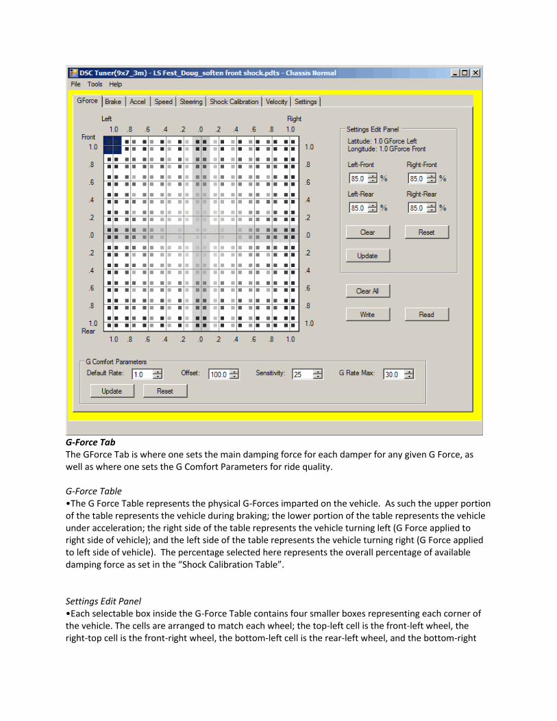
G-Force Tab The GForce Tab is where one sets the main damping force for each damper for any given G Force, as well as where one sets the G Comfort Parameters for ride quality. G-Force Table •The G Force Table represents the physical G-Forces imparted on the vehicle. As such the upper portion of the table represents the vehicle during braking; the lower portion of the table represents the vehicle under acceleration; the right side of the table represents the vehicle turning left (G Force applied to right side of vehicle); and the left side of the table represents the vehicle turning right (G Force applied to left side of vehicle). The percentage selected here represents the overall percentage of available damping force as set in the “Shock Calibration Table”. Settings Edit Panel •Each selectable box inside the G-Force Table contains four smaller boxes representing each corner of the vehicle. The cells are arranged to match each wheel; the top-left cell is the front-left wheel, the right-top cell is the front-right wheel, the bottom-left cell is the rear-left wheel, and the bottom-right

cell is the rear-right wheel. The dampers are set in each box by changing the percentage in the Settings Edit Panel. The percentage selected here represents the overall percentage of available damping force as set in the “Shock Calibration Table”. Shades of grey directly correlate to the shock calibration table. Always remember to hit update to save in the cell you are editing. G Comfort Parameters Box •The G Comfort Parameters Box determines ride quality when there is little to no G Force. The G Comfort Parameters Box can be set to any G-Force value, thereby influencing ride quality from 0G’s to 0.4G’s in any direction, for example. •Default Rate This is the “Default” soft shock setting when operating inside the “G patch” or “box”. This number is the % from the shock calibration table. So if a 1 or 15 is present, 1% or 15% of the shock calibration will be applied. •Offset This is a calculated value and is always set to 100 on the new units. •Rate of Change (Sensitivity) This is the rate of change within the box, the Patch. The greater the number, the higher the sensitivity. This means the you will not deviate from the Default rate (Lng rate) as quickly. The smaller the number, the lower the sensitivity. This means you will deviate from the Default rate (Lng rate) more quickly. Therefore this is why we have a lower number in “sport” mode (10) compared to “normal” mode (15). •G Rate Max This number defines the “box,” or G Patch. You need to move the decimal to the left 2 places, then you view this number as a G force value. So if we have a 20 present, that would be .2G. Within this .2G box, the Default rate (Lng Rate) applies. The size of the box can be from .3G to .1G, anything outside of this can have some un-desirable effects.
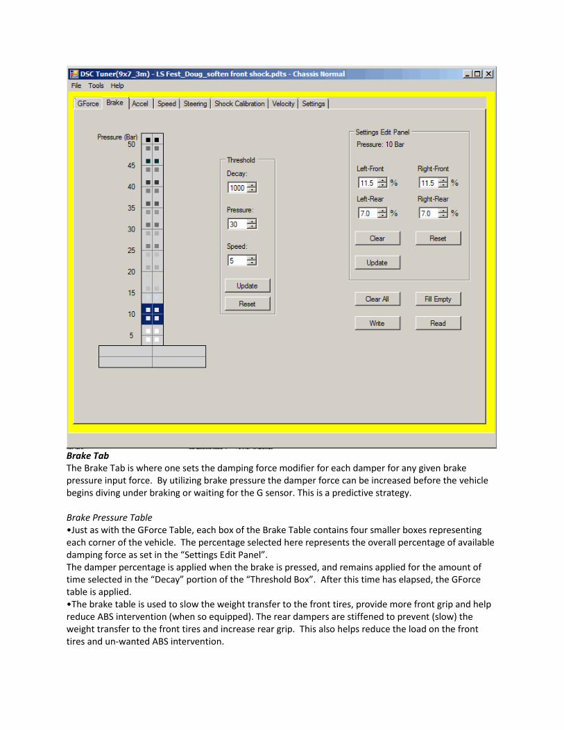
Brake Tab The Brake Tab is where one sets the damping force modifier for each damper for any given brake pressure input force. By utilizing brake pressure the damper force can be increased before the vehicle begins diving under braking or waiting for the G sensor. This is a predictive strategy. Brake Pressure Table •Just as with the GForce Table, each box of the Brake Table contains four smaller boxes representing each corner of the vehicle. The percentage selected here represents the overall percentage of available damping force as set in the “Settings Edit Panel”. The damper percentage is applied when the brake is pressed, and remains applied for the amount of time selected in the “Decay” portion of the “Threshold Box”. After this time has elapsed, the GForce table is applied. •The brake table is used to slow the weight transfer to the front tires, provide more front grip and help reduce ABS intervention (when so equipped). The rear dampers are stiffened to prevent (slow) the weight transfer to the front tires and increase rear grip. This also helps reduce the load on the front tires and un-wanted ABS intervention.
Settings Edit Panel •Each selectable box inside the G-Force Table contains four smaller boxes representing each corner of the vehicle. The cells are arranged to match each wheel; the top-left cell is the front-left wheel, the right-top cell is the front-right wheel, the bottom-left cell is the rear-left wheel, and the bottom-right cell is the rear-right wheel. The dampers are set in each box by changing the percentage in the Settings Edit Panel. The percentage selected here represents the overall percentage of available damping force as set in the “Shock Calibration Table”. Shades of grey directly correlate to the shock calibration table. Always remember to hit update to save in the cell you are editing. Threshold Box •The Threshold Box allows one to set the amount of time the damper force is applied once a set brake pressure has been exceeded and the vehicle is over a set minimum speed. •Decay The Brake Pressure Table is applied before the GForce Table is referenced. It is only active for the specified “decay” value. This is usually set to 1000. 1000 = 1.0sec; 0500 = 0.5sec; etc •Pressure This table is only active when you reach the set brake pressure setting, and is calculated as BAR per millisecond. •Speed This table is only active once you exceed the minimum speed. It is typically set to 5mph.
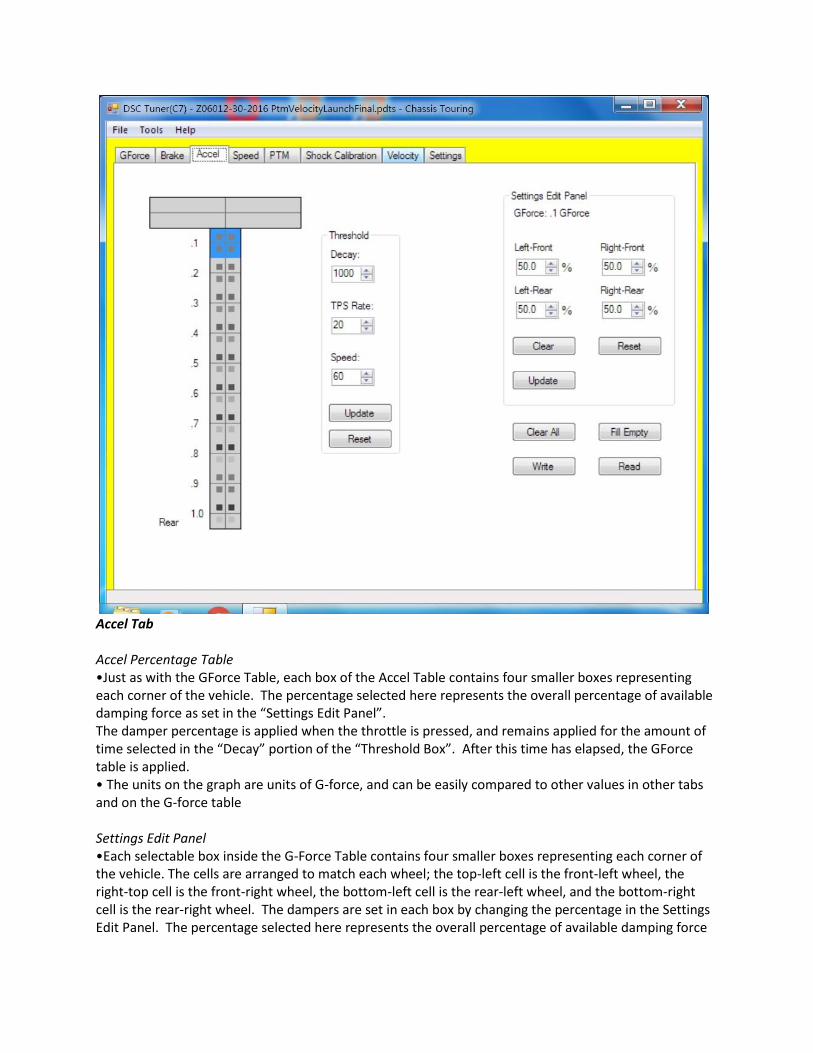
Accel Tab Accel Percentage Table •Just as with the GForce Table, each box of the Accel Table contains four smaller boxes representing each corner of the vehicle. The percentage selected here represents the overall percentage of available damping force as set in the “Settings Edit Panel”. The damper percentage is applied when the throttle is pressed, and remains applied for the amount of time selected in the “Decay” portion of the “Threshold Box”. After this time has elapsed, the GForce table is applied. • The units on the graph are units of G-force, and can be easily compared to other values in other tabs and on the G-force table Settings Edit Panel •Each selectable box inside the G-Force Table contains four smaller boxes representing each corner of the vehicle. The cells are arranged to match each wheel; the top-left cell is the front-left wheel, the right-top cell is the front-right wheel, the bottom-left cell is the rear-left wheel, and the bottom-right cell is the rear-right wheel. The dampers are set in each box by changing the percentage in the Settings Edit Panel. The percentage selected here represents the overall percentage of available damping force
as set in the “Shock Calibration Table”. Shades of grey directly correlate to the shock calibration table. Always remember to hit update to save in the cell you are editing. Threshold Box •The Threshold Box allows one to set the amount of time the damper force is applied once a set throttle position has been exceeded and the vehicle is over a set minimum speed. •Decay The Accel Percentage Table is applied before the GForce Table is referenced. It is only active for the specified “decay” value. This is usually set to 1000. 1000 = 1.0sec; 0500 = 0.5sec; etc •TPS This table is only active when you reach the set throttle position rate setting, and is calculated as a percentage of maximum throttle. •Speed This table is only active up to the target speed. It is typically set to 60mph.

Speed Tab The Speed Tab is where one sets the speed at which the system does or does not influence overall damper force. The settings on this tab are used to provide stability as the vehicle speed increases from 60 to 150mph. Over 150mph, the last group of cells extrapolates out. The percentages selected in the Settings Edit Panel for each speed are added to the percentages in the GForce table when the vehicle is at or above the set speed and below the GForce setting in the Speed G-Limit Threshold. Speed Table • The Speed Table has 60mph on the left, and 150mph on the right. •The calibration can be changed the same way the shock calibration can be changed. Clear all values, input your 60mph values and your 150mph values, then click “fill empty” and the system will interpolate the rest. Settings Edit Panel •Each selectable box inside the G-Force Table contains four smaller boxes representing each corner of the vehicle. The cells are arranged to match each wheel; the top-left cell is the front-left wheel, the

right-top cell is the front-right wheel, the bottom-left cell is the rear-left wheel, and the bottom-right cell is the rear-right wheel. The dampers are set in each box by changing the percentage in the Settings Edit Panel. The percentage selected here represents the overall percentage of available damping force as set in the “Shock Calibration Table”. Shades of grey directly correlate to the shock calibration table. Always remember to hit update to save in the cell you are editing. Speed G-Limit Threshold Box •This setting controls when the speed table is actively influencing the force of the dampers. •Units are usually setup with .30G per second in all 4 values. This means when the car exceeds .3G per second in any direction, the speed table will no longer be applied in addition to the G-Force table.

Steering Tab
The Steering Tab contains the steering angle table. This table is used to predict the rate of change in
wheel angle as you turn the steering wheel. This tab is not used in the core tuning program, but is an
additional option for tuning if you want to use it. We use this table in some applications for ten position
global offset for racing and tuning.
Settings Edit Panel •Each selectable box inside the G-Force Table contains four smaller boxes representing each corner of the vehicle. The cells are arranged to match each wheel; the top-left cell is the front-left wheel, the right-top cell is the front-right wheel, the bottom-left cell is the rear-left wheel, and the bottom-right cell is the rear-right wheel. The dampers are set in each box by changing the percentage in the Settings Edit Panel. The percentage selected here represents the overall percentage of available damping force as set in the “Shock Calibration Table”. Always remember to hit update to save in the cell you are editing.

Steering Angle (Rate of Change) Table
•A predictive way to determine weight transfer based on steering. Shades of grey directly correlate to
the shock calibration table. The CCW (Counter-clockwise) end of the table refers to the rate or wheel
angle change caused by turning the wheel counterclockwise and the CW (Clockwise) end of the table
refers to the rate or wheel angle change caused by turning the wheel clockwise.
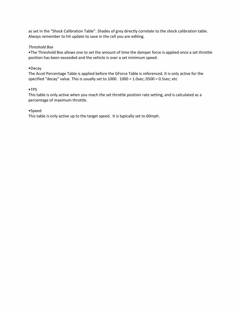
Shock Calibration Tab The Shock Calibration Tab contains the Shock Calibration Table. This is the most important and influential table as all other tables reference it. The Shock Calibration Table has 0% of current being used on the left, and 100% of current being used on the right. The Shock Calibration Tab is where one sets up the amount of current the damper is allowed to use. Damper operating range •With OE dampers, 1500ma is to be considered full soft and 500ma is full stiff. •With Tractive dampers, 1900ma is to be considered full soft and 500ma is full stiff. •With magnetic shocks, 0ma is considered to be full soft and 1000ma is full stiff. •Building a new shock calibration To build a linear shock calibration table proceed as follows -Click the “clear all” button. -Input the 0% values. To do this you must click on the respective cell and input the desired ma in the “calibrated at” box. Then click the “update” box. Do this for all 4 of the 0% cells.

-Then set your 100% cells in the same manner. -Once you have done this, click the “fill empty” button and the software will interpolate the remaining cells. Writing the new shock calibration •Make sure that under the read and write boxes that “all” is selected. Then double check what mode you will be writing this calibration to. To do this, click on the settings tab, take note what mode you are altering, ie “normal” or “sport” and then confirm what mode you will be writing to, “normal” or “sport”. •Go back to the shock calibration tab and click the “write” button. •It is then a good idea to reset the board. Click the tools menu, select “reset board”.
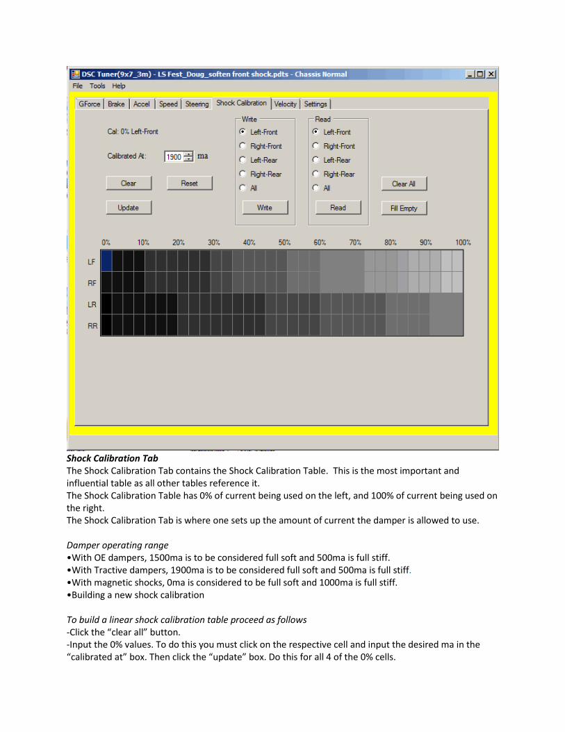
Velocity Tab
Velocity tuning is available for all cars that are ride-height equipped (most V2 controller-based cars).
Compression and Rebound table •Representation of low (0-3 IN/sec), medium (3-5 IN/sec), high (5-8 IN/sec) speed compression and rebound based on the travel speed of the shocks. Darker shades indicate a positive percentage change (more damping) from what the shocks were calibrated at while lighter shades indicate a negative percentage change (less damping) from what the shocks were calibrated at. •When looking at the table, “0” is static ride height, at the current time you will use 3 cells to left and 3 cell to the right of zero. The table will be from zero to 8” per second for compression and rebound. Compression is the Negative values, left side of the table; Rebound is the Positive values, right side of table. •Please note cars should be zero travelled at ride height with driver on set-up table (see setting tab). Travel Stops
•The values for the maximum compression and drop for each of the shocks, which influences the values
in the compression and rebound table.

PTM Tab (C7 shown)
Setting Table
•The table indicated what percentage will be sent offset globally to the different settings; darker shades
indicating higher percentage is sent while lighter shades indicate less percentage.
Settings Edit Panel •Each selectable box inside the G-Force Table contains four smaller boxes representing each corner of
the vehicle. The cells are arranged to match each wheel; the top-left cell is the front-left wheel, the
right-top cell is the front-right wheel, the bottom-left cell is the rear-left wheel, and the bottom-right
cell is the rear-right wheel. The current is set in each box by changing the percentage in the Settings Edit
Panel. The percentage selected here represents the overall percentage of available current set in the
“Shock Calibration Table”. Shades of grey directly correlate to the shock calibration table. Always
remember to hit update to save in the cell you are editing.
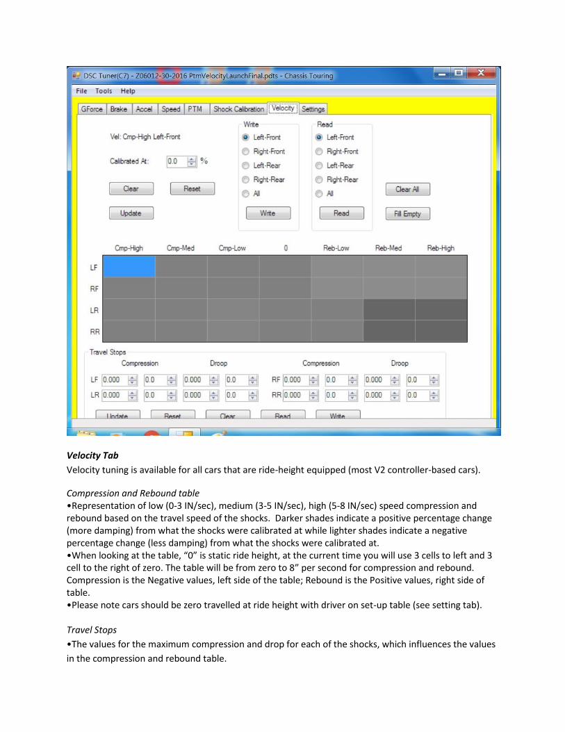
Settings Tab The Settings Tab is where the selection for reading and writing to and from the ECU, Mode to edit (Normal, Sport, Track) and which mode to write to the ECU after editing is complete. Each Mode is easily identified by the color of the outline on all Tabs: (this is not to be confused with overall reading and writing the read all and write all is done under the tools drop down) Normal: Yellow Sport: Red Track: Blue Read from DSC •Select the Mode which you wish to read from Write to DSC •Select the Mode which you wish to write to ZERO TRAVEL (critical for velocity table to be fully functional)

Zero Travel is used on all cars with ride height sensors or travel sensors. This is primarily used in all V2 DSC ecus It is imperative for peak performance of the velocity table to Zero Travel follow the prompt Note: car must be on level surface or setup table with driver tires set to operating pressure
Command Line Interface (This interface is used primarily for troubleshooting reading codes “i” command is used to look for codes and “v” command is used to see the version) •Accessing commands = Under the tools menu, select “test serial port”. Click “start”. In the write out box, this is where you will enter command then enter key •A command = This command is used to set the dampers to full soft, 1500 ma. You can use this function when doing a setup or to test the shocks, wiring, connections etc. Enter A in the write out box and hit enter. It will then prompt you to enter Y or N to confirm your selection. •X command = Use this command to clear fault codes. •I command = Use this command to read out fault codes. Codes are displayed numerically 1-14. Use this command as a diagnostic tool. Data logging •Under the tools menu, select “switch input” this is where you will select what inputs you wish to record. Click “set” to confirm your selections. •Recording data = Under the tools menu, select “record”. On the display menu, click the “circle” to start recording. The laptop must be in the car and connected to record! Once you are done recording, click the “square” to stop. Save your file in your DSC folder on your desktop. Each unit in the display represents 1 tenth of a second. This is the time domain. •Text view = You can also view the data in a text view. Select the “text” tab next to the “graph” tab to toggle views.