dse8660 mkii pc software manual - dornamehr.com
TRANSCRIPT

057-238 ISSUE: 6
DEEP SEA ELECTRONICS DSE8660 MKII Configuration Suite
PC Software Manual
Document Number: 057-257
Author: Ashley Senior

DSE8660 MKII Configuration Suite PC Software Manual
057-238 ISSUE: 6 Page 2 of 168
Deep Sea Electronics Ltd. Highfield House Hunmanby North Yorkshire YO14 0PH England Sales Tel: +44 (0) 1723 890099 E-mail: [email protected] Website: www.deepseaelectronics.com DSE8660 MKII Configuration Suite PC Software Manual © Deep Sea Electronics Ltd. All rights reserved. No part of this publication may be reproduced in any material form (including photocopying or storing in any medium by electronic means or other) without the written permission of the copyright holder except in accordance with the provisions of the Copyright, Designs and Patents Act 1988. Applications for the copyright holder’s written permission to reproduce any part of this publication must be addressed to Deep Sea Electronics Ltd. at the address above. The DSE logo and the names DSEGenset®, DSEATS®, DSEPower® and DSEControl® are UK registered trademarks of Deep Sea Electronics Ltd. Any reference to trademarked product names used within this publication is owned by their respective companies. Deep Sea Electronics Ltd. reserves the right to change the contents of this document without prior notice. Amendments Since Last Publication
Amd. No. Comments
1 Initial Release
2 Updated to include features added in module firmware V2.0 and V3.0
3 Updated to include features added in modules Firmware V5
4 Updated to include features added in module firmware V5.1
5 Updated to module firmware V6.1, features include: Fault Ride Through, Advanced PLC Editor, Disable Auto MSC-ID Allocation, new Load Demand Scheme
6 Updated to module firmware V7, features include: Manual Bus Adjust, Load Demand Compatibility option, MSC PLC Data, and more…
Typeface: The typeface used in this document is Arial. Care must be taken not to mistake the upper-case letter I with the numeral 1. The numeral 1 has a top serif to avoid this confusion.

DSE8660 MKII Configuration Suite PC Software Manual
Page 3 of 168 057-238 ISSUE: 6
TABLE OF CONTENTS
Section Page
1 INTRODUCTION .................................................................................................. 6 1.1 CLARIFICATION OF NOTATION ............................................................................................ 7 1.2 GLOSSARY OF TERMS .......................................................................................................... 7 1.3 BIBLIOGRAPHY ...................................................................................................................... 8
1.3.1 INSTALLATION INSTRUCTIONS ..................................................................................... 8 1.3.2 MANUALS ......................................................................................................................... 8 1.3.3 TRAINING GUIDES .......................................................................................................... 9 1.3.4 THIRD PARTY DOCUMENTS ........................................................................................ 10
1.4 INSTALLATION AND USING THE DSE CONFIGURATION SUITE SOFTWARE .............. 10
2 EDITING THE CONFIGURATION ..................................................................... 11 2.1 SCREEN LAYOUT ................................................................................................................. 11 2.2 MODULE ................................................................................................................................ 12
2.2.1 MODULE OPTIONS ........................................................................................................ 12 2.2.2 CONFIGURABLE STATUS SCREENS .......................................................................... 17 2.2.3 EVENT LOG .................................................................................................................... 19 2.2.4 DATA LOGGING ............................................................................................................. 20
2.2.4.1 CONFIGURATION ................................................................................................... 21 2.2.4.2 OPTIONS ................................................................................................................. 22
2.3 DIGITAL INPUTS ................................................................................................................... 23 2.3.1 DIGITAL INPUTS ............................................................................................................ 23 2.3.2 INPUT FUNCTIONS ........................................................................................................ 25
2.4 OUTPUTS ............................................................................................................................... 30 2.4.1 DIGITAL OUTPUTS ........................................................................................................ 30 2.4.2 VIRTUAL LEDS ............................................................................................................... 31 2.4.3 OUTPUT SOURCES ....................................................................................................... 32
2.5 TIMERS .................................................................................................................................. 40 2.5.1 START TIMERS .............................................................................................................. 40 2.5.2 LOAD / STOPPING TIMERS .......................................................................................... 41 2.5.3 MODULE TIMERS .......................................................................................................... 41
2.6 MAINS .................................................................................................................................... 42 2.6.1 MAINS OPTIONS ............................................................................................................ 43 2.6.2 MAINS VOLTAGE ALARMS ........................................................................................... 45 2.6.3 MAINS SEQUENCE ALARMS ........................................................................................ 46 2.6.4 MAINS FREQUENCY ALARMS ...................................................................................... 48 2.6.5 CURRENT ....................................................................................................................... 49 2.6.6 MAINS DECOUPLING .................................................................................................... 51
2.6.6.1 LOSS OF MAINS ..................................................................................................... 52 2.6.6.2 VOLTAGE ALARMS ................................................................................................ 53 2.6.6.3 FREQUENCY ........................................................................................................... 55
2.6.7 FAULT RIDE THROUGH ................................................................................................ 57 2.7 BUS ........................................................................................................................................ 60
2.7.1 BUS OPTIONS ................................................................................................................ 61 2.7.2 BUS NOMINALS ............................................................................................................. 63 2.7.3 BUS SEQUENCE ALARMS ............................................................................................ 64 2.7.4 CHECK SYNC ................................................................................................................. 66 2.7.5 MULTISET ....................................................................................................................... 68 2.7.6 LOAD CONTROL ............................................................................................................ 73 2.7.7 POWER CONTROL ........................................................................................................ 75
2.7.7.1 CREATING / EDITING THE POWER MODE CURVE ............................................ 78 2.7.8 VOLTAGE AND REACTIVE POWER CONTROL .......................................................... 79
2.8 SYSTEM ................................................................................................................................. 82 2.8.1 SYSTEM OPTIONS ........................................................................................................ 82 2.8.2 PLANT BATTERY ........................................................................................................... 84
2.9 COMMUNICATIONS .............................................................................................................. 85 2.9.1 COMMUNICATIONS OPTIONS ...................................................................................... 85

DSE8660 MKII Configuration Suite PC Software Manual
057-238 ISSUE: 6 Page 4 of 168
2.9.2 RS232 PORT ................................................................................................................... 86 2.9.2.1 BASIC ....................................................................................................................... 87 2.9.2.2 ADVANCED ............................................................................................................. 90 2.9.2.3 SMS CONTROL ....................................................................................................... 92 2.9.2.4 TROUBLESHOOTING MODEM COMMUNICATIONS ........................................... 93
2.9.2.4.1 MODEM COMMUNICATION SPEED SETTING .................................................. 93 2.9.2.4.2 GSM MODEM CONNECTION ............................................................................. 93
2.9.3 RS485 PORTS ................................................................................................................ 94 2.9.4 ETHERNET ..................................................................................................................... 95
2.9.4.1 FIREWALL CONFIGURATION FOR INTERNET ACCESS .................................... 97 2.9.4.2 INCOMING TRAFFIC (VIRTUAL SERVER) ............................................................ 97
2.9.5 NOTIFICATIONS ............................................................................................................. 98 2.9.5.1 SNMP ....................................................................................................................... 98 2.9.5.2 NOTIFICATIONS ..................................................................................................... 99
2.10 SCHEDULER .................................................................................................................... 100 2.10.1 SCHEDULER OPTIONS ............................................................................................... 100 2.10.2 BANK 1 / BANK 2 .......................................................................................................... 101
2.11 EXPANSION ..................................................................................................................... 102 2.11.1 DSE2130 INPUT MODULES ........................................................................................ 103
2.11.1.1 ANALOGUE INPUT CONFIGURATION ................................................................ 104 2.11.1.2 ANALOGUE INPUTS ............................................................................................. 104
2.11.1.2.1 CREATING / EDITING THE SENSOR CURVE ............................................... 106 2.11.1.3 DIGITAL INPUTS ................................................................................................... 108
2.11.1.3.1 DIGITAL INPUTS ............................................................................................. 109 2.11.1.3.2 ANALOGUE INPUTS ....................................................................................... 110
2.11.2 DSE2131 INPUT MODULES ........................................................................................ 111 2.11.2.1 ANALOGUE INPUT CONFIGURATION ................................................................ 112 2.11.2.2 ANALOGUE INPUTS ............................................................................................. 113 2.11.2.3 DIGITAL INPUTS ................................................................................................... 115
2.11.3 DSE2133 INPUT MODULES ........................................................................................ 117 2.11.3.1 ANALOGUE INPUTS ............................................................................................. 118
2.11.4 DSE2152 OUTPUT MODULES .................................................................................... 120 2.11.4.1 ANALOGUE OUTPUTS ......................................................................................... 121 2.11.4.2 CREATING / EDITING THE OUTPUT CURVE ..................................................... 122
2.11.5 DSE2157 RELAY MODULES ....................................................................................... 124 2.11.6 DSE2548 ANNUCIATOR MODULES ........................................................................... 125 2.11.7 BATTERY CHARGERS ................................................................................................ 127
2.12 ADVANCED ...................................................................................................................... 129 2.12.1 ADVANCED OPTIONS ................................................................................................. 130 2.12.2 PLC ................................................................................................................................ 133 2.12.3 CONFIGURABLE GENCOMM PAGES 166 TO 169 .................................................... 134 2.12.4 CONFIGURABLE EDITOR SCREENS ......................................................................... 136
3 SCADA ............................................................................................................ 137 3.1 MAINS IDENTITY ................................................................................................................. 138 3.2 MIMIC ................................................................................................................................... 138 3.3 DIGITAL INPUTS ................................................................................................................. 139 3.4 DIGITAL OUTPUTS ............................................................................................................. 140 3.5 VIRTUAL LEDS .................................................................................................................... 141 3.6 BUS ...................................................................................................................................... 142
3.6.1 FREQUENCY AND VOLTAGES ................................................................................... 142 3.6.2 LOAD ............................................................................................................................. 143 3.6.3 MSC LINK ...................................................................................................................... 144 3.6.4 SYNC ............................................................................................................................. 145 3.6.5 LOAD LEVELS .............................................................................................................. 146
3.7 MAINS .................................................................................................................................. 149 3.7.1 FREQUENCY AND VOLTAGES ................................................................................... 149 3.7.2 POWER ......................................................................................................................... 150
3.8 ALARMS .............................................................................................................................. 151 3.9 STATUS ............................................................................................................................... 152

DSE8660 MKII Configuration Suite PC Software Manual
Page 5 of 168 057-238 ISSUE: 6
3.10 EVENT LOG ..................................................................................................................... 153 3.11 REMOTE CONTROL ........................................................................................................ 154 3.12 MAINTENANCE................................................................................................................ 155
3.12.1 EXPANSION CALIBRATION ........................................................................................ 156 3.12.2 TIME .............................................................................................................................. 157 3.12.3 ACCUMULATED INSTRUMENTATION ....................................................................... 158 3.12.4 MODULE PIN ................................................................................................................ 159
3.13 COMMUNICATIONS INFORMATION .............................................................................. 160 3.14 DATA LOG ....................................................................................................................... 161 3.15 PLC ................................................................................................................................... 162
3.15.1 PLC LOGIC ................................................................................................................... 162 3.15.2 PLC STORES ................................................................................................................ 163
3.16 EXPANSION ..................................................................................................................... 164
4 ALARM TYPES................................................................................................ 165
5 ALARM ARMING ............................................................................................. 166 5.1 NEVER ................................................................................................................................. 166 5.2 ALWAYS .............................................................................................................................. 166 5.3 ACTIVE FROM MAINS PARALLEL .................................................................................... 166
Introduction
057-238 ISSUE: 6 Page 6 of 168
1 INTRODUCTION This document details the use of the DSE Configuration Suite PC Software with the DSE8660 MKII module, which is part of the DSEGenset® range of products. The manual forms part of the product and should be kept for the entire life of the product. If the product is passed or supplied to another party, ensure that this document is passed to them for reference purposes. This is not a controlled document. DSE do not automatically inform on updates. Any future updates of this document are included on the DSE website at www.deepseaelectronics.com The DSE Configuration Suite PC Software allows the DSE8660 MKII module to be connected to a PC via USB A to USB B cable (USB printer cable). Once connected, the software allows easy, controlled access to various operating parameters within the module which can then be viewed and edited as required. The DSE Configuration Suite PC Software must only be used by competent, qualified personnel, as changes to the operation of the module may have safety implications on the panel to which it is fitted. Access to critical operational sequences and settings for use by qualified engineers, may be barred by a security code set by the Generator / panel provider. The information contained in this manual must be read in conjunction with the information contained in the appropriate module documentation. This manual only detail which settings are available and how they may be used. Separate manuals deal with the operation of the individual module and its ancillaries, refer to section entitled Bibliography elsewhere in this document for further information.

Introduction
Page 7 of 168 057-238 ISSUE: 6
1.1 CLARIFICATION OF NOTATION Clarification of notation used within this publication.
NOTE:
Highlights an essential element of a procedure to ensure correctness.
CAUTION!
Indicates a procedure or practice, which, if not strictly observed, could result in damage or destruction of equipment.
WARNING!
Indicates a procedure or practice, which could result in injury to personnel or loss of life if not followed correctly.
1.2 GLOSSARY OF TERMS
Term Description
DSE8000 MKII, DSE8xxx MKII
All modules in the DSE8xxx MKII range.
DSE8600 MKII, DSE86xx MKII
All modules in the DSE86xx MKII range.
DSE8660 MKII DSE8660 MKII module/controller
DSE8x10 DSE8610, DSE8610 MKII, DSE8710 and DSE8810 module/controller
DSE8x60 DSE8660, DSE8660 MKII, DSE8760 and DSE8860 module/controller
DSE8x80 DSE8680 module/controller
CAN Controller Area Network Vehicle standard to allow digital devices to communicate to one another.
CDMA Code Division Multiple Access. Cell phone access used in small number of areas including parts of the USA and Australia.
CT Current Transformer An electrical device that takes a large AC current and scales it down by a fixed ratio to a smaller current.
BMS Building Management System A digital/computer-based control system for a building’s infrastructure.
GSM Global System for Mobile communications. Cell phone technology used in most of the World.
HMI Human Machine Interface A device that provides a control and visualisation interface between a human and a process or machine.
IDMT Inverse Definite Minimum Time
IEEE Institute of Electrical and Electronics Engineers
LED Light Emitting Diode
MSC Multi-Set Communication
PLC Programmable Logic Controller A programmable digital device used to create logic for a specific purpose.
R.O.C.O.F. Rate Of Change Of Frequency
SCADA Supervisory Control And Data Acquisition A system that operates with coded signals over communication channels to provide control and monitoring of remote equipment
SIM Subscriber Identity Module. The small card supplied by the GSM/CDMA provider that is inserted into the cell phone, GSM modem or DSEGateway device to give GSM/GPRS connection.
SMS Short Message Service The text messaging service of mobile/cell phones.
SNMP Simple Network Management Protocol An international standard protocol for managing devices on IP networks.

Introduction
057-238 ISSUE: 6 Page 8 of 168
1.3 BIBLIOGRAPHY This document refers to, and is referred by the following DSE publications which are obtained from the DSE website: www.deepseaelectronics.com or by contacting DSE technical support: [email protected].
1.3.1 INSTALLATION INSTRUCTIONS Installation instructions are supplied with the product in the box and are intended as a ‘quick start’ guide only.
DSE Part Description
053-032 DSE2548 LED Expansion Annunciator Installation Instructions
053-033 DSE2130 Input Expansion Installation Instructions
053-034 DSE2157 Output Expansion Installation Instructions
053-049 DSE9xxx Battery Charger Installation Instructions
053-082 DSE8680 Installation Instructions
053-125 DSE2131 Ratio-metric Input Expansion Installation Instructions
053-126 DSE2133 RTD/Thermocouple Input Expansion Installation Instructions
053-134 DSE2152 Ratio-metric Output Expansion Installation Instructions
053-147 DSE9460 & DSE9461 Battery Charger Installation Instructions
053-182 DSE8610 MKII Installation Instructions
053-184 DSE8660 MKII Installation Instructions
053-185 DSE9473 & DSE9483 Battery Charger Installation Instructions
053-248 DSE8920 Installation Instructions
1.3.2 MANUALS Product manuals are obtained from the DSE website: www.deepseaelectronics.com or by contacting DSE technical support: [email protected].
DSE Part Description
N/A DSEGencomm (MODBUS protocol for DSE controllers)
057-045 Guide to Synchronising and Load Sharing Part 1 (Usage of DSE Load Share Controllers in synchronisation / load sharing systems.)
057-046 Guide to Synchronising and Load Sharing Part 2 (Governor & AVR Interfacing)
057-047 Load Share System Design and Commissioning Guide
057-082 DSE2130 Input Expansion Operator Manual
057-083 DSE2157 Output Expansion Operator Manual
057-084 DSE2548 Annunciator Expansion Operator Manual
057-085 DSE9xxx Battery Charger Operator Manual
057-130 DSE8680 Operator Manual
057-131 DSE8680 Configuration Suite PC Software Manual
057-139 DSE2131 Ratio-metric Input Expansion Manual
057-140 DSE2133 RTD/Thermocouple Expansion Manual
057-141 DSE2152 Ratio-metric Output Expansion Manual
057-151 DSE Configuration Suite PC Software Installation & Operation Manual
057-175 PLC Programming Guide for DSE Controllers
057-176 DSE9460 & DSE9461 Battery Charger Operator Manual
057-238 DSE8610 MKII Configuration Suite PC Software Manual
057-257 DSE8660 MKII Configuration Suite PC Software Manual
057-259 DSE8660 MKII Operator Manual
057-305 DSSE8910 Configuration Suite PC Software Manual
057-310 DSSE8910 Operators Manual
057-312 DSEAssistant PC Software Manual
057-314 Advanced PLC Software Manual

Introduction
Page 9 of 168 057-238 ISSUE: 6
1.3.3 TRAINING GUIDES Training guides are provided as ‘hand-out’ sheets on specific subjects during training sessions and contain specific information regarding to that subject.
DSE Part Description
056-001 Four Steps To Synchronising
056-005 Using CTs With DSE Products
056-006 Introduction to Comms
056-011 MSC Link
056-013 Load Demand Scheme
056-021 Mains Decoupling
056-022 Switchgear Control
056-024 GSM Modem
056-026 kVA, kW, kvar and Power Factor
056-030 Module PIN Codes
056-033 Synchronising Requirements
056-036 Expansion Modules
056-043 Sync Process
056-045 PLC as Load Demand Controller
056-047 Out of Sync and Failed To Close
056-051 Sending DSEGencomm Control Keys
056-053 Recommended Modems
056-069 Firmware Update
056-075 Adding Language Files
056-076 Reading DSEGencomm Alarms
056-079 Reading DSEGencomm Status
056-080 MODBUS
056-081 Screen Heaters
056-082 Override Gencomm PLC Example
056-084 Synchronising & Loadsharing
056-086 G59
056-089 DSE86xx MKI to DSE86xx MKII Conversion
056-091 Equipotential Earth Bonding
056-092 Best Practices for Wiring Restive Sensors
056-094 MSC Compatibility
056-095 Remote Start Input Functions
056-097 USB Earth Loops and Isolation
056-099 Digital Output to Digital Input Connection

Introduction
057-238 ISSUE: 6 Page 10 of 168
1.3.4 THIRD PARTY DOCUMENTS The following third-party documents are also referred to:
Reference Description
ISBN 1-55937-879-4 IEEE Std C37.2-1996 IEEE Standard Electrical Power System Device Function Numbers and Contact Designations. Institute of Electrical and Electronics Engineers Inc
ISBN 0-7506-1147-2 Diesel Generator handbook. L.L.J. Mahon
ISBN 0-9625949-3-8 On-Site Power Generation. EGSA Education Committee.
1.4 INSTALLATION AND USING THE DSE CONFIGURATION SUITE SOFTWARE
For information in regards to installing and using the DSE Configuration Suite PC Software, refer to DSE publication: 057-151 DSE Configuration Suite PC Software Installation & Operation Manual which is found on the DSE website: www.deepseaelectronics.com

Editing the Configuration
Page 11 of 168 057-238 ISSUE: 6
2 EDITING THE CONFIGURATION The software is broken down into separate sections to provide simple navigation whilst editing the module’s configuration to suit a particular application.
2.1 SCREEN LAYOUT
The type of module configuration file being edited
The coloured shading shows the currently selected page/section
Click + or – to expand or collapse the section
Click to move to the Previous or Next section
Click to close the opened configuration file
Click to step Forward or Back through previously viewed configuration sections
Click to return to the Home section shown below
Click to view / edit the section

Editing the Configuration
057-238 ISSUE: 6 Page 12 of 168
2.2 MODULE The Module section allows the user to edit options related to the module itself and is subdivided into smaller sections.
2.2.1 MODULE OPTIONS Description
Parameter Description
Description Four free entry boxes to allow the user to give the configuration file a description. Typically used to enter the job number, customer name, site information etc. This text is not shown on the module’s display and is only seen in the configuration file.
LED Indicators
Parameter Description
Function Allows the user to assign an output source to an LED indicator which are to the right of the module’s LCD. For details of possible selections, see section entitled Output Sources elsewhere in this document.
Polarity Lit: When the output source is true, the LCD indicator activates. Unlit: When the output source is true, the LCD indicator de-activates.
Insert Card Text Enter custom text to print on the text insert for the LEDs.
Text Insert Allows the user to print the custom text insert cards for the LEDs.
Logo Insert Allow the user to choose and print an image for the logo insert above the LCD.
Click to view / edit the section

Editing the Configuration
Page 13 of 168 057-238 ISSUE: 6
Rear Mount Option
Option Description
Enable Auto Voltage Sensing
NOTE: For further details on supported displays when the DSE module is mounted into the rear of the panel, contact DSE Technical Support [email protected].
= The module’s display, fascia buttons and LEDs are enabled and is to be mounted on the fascia of the panel. = The Rear Mount Option is enabled. The module’s display, fascia buttons and LEDs are disabled to allow the module to be mount in the rear of a panel using the DSE Rear Mount Panel Bracket; Part Number 020-1044. A remote display is required to provide local monitoring and control of the system.
Miscellaneous Options
Parameter Description
Enable Running On Load Demand IEEE 37.2 - 44 Unit sequence starting
= The Running on Load Demand is disabled. When remote start request is sent down the MSC link, all the generators run regardless of the amount of load. = The Running on Load Demand is enabled. When remote start request is sent down the MSC link, only the generators required to support the load run.
All Warnings Are Latched = The All Warnings Are Latched is disabled. The module automatically resets the warning and pre-alarms once the triggering condition has been cleared. = The All Warnings Are Latched is enabled. The module does not automatically reset the warning and pre-alarms. Resetting the alarm is performed by either activating a digital input configured for Alarm
Reset or, pressing the Stop/Reset Mode button once the triggering condition has been cleared.
Enable Immediate Mains Dropout
= The Immediate Mains Dropout is disabled. Upon Mains failure, the Mains switchgear is kept closed until the Generator Bus is up to speed and volts. = The Immediate Mains Dropout is enabled. Upon Mains failure, the Mains switchgear is opened immediately, subject to the setting of the Mains Transient timer.
Parameter descriptions are continued overleaf…

Editing the Configuration
057-238 ISSUE: 6 Page 14 of 168
Parameter Description
Inhibit Retransfer to Mains IEEE 37.2 - 3 Checking or interlocking relay
= The Inhibit Retransfer to Mains is disabled. When the Generator Bus is running on load and fails, the load is transferred back to the mains. = The Inhibit Retransfer to Mains is enabled. The load is prevented from being transferred back to the Mains supply, only in the event of the Generator Bus failure. This is used in peak lopping systems where the cost of using the Mains to supply the load is so prohibitive that the customer does not want to transfer back to the Mains supply.
Enable Forced Peak Lop Inhibit NOTE: This option only has effect in Manual Mode.
If the module is Peak Lopping in Auto Mode and another DSExx60 requests to control the Generator Bus following a Mains failure, the Peak Lopping operation is suspended.
= The Forced Peak Lop Inhibit is disabled. The module continues to control the Generator Bus regardless if another DSExx60 requests control. = The Forced Peak Lop Inhibit is enabled. If the DSExx60 (1) is in Manual Mode controlling the Generator Bus for peak lopping and another DSExx60 (2) requests the generators to power its load following a Mains failure, the DSExx60 MKII (1) relinquishes control over the Generator Bus to the other DSExx60 MKII (2).
Support Right-To-Left Languages in Module Strings
= The Support Right-To-Left Languages in Module Strings is disabled. The module displays user configured strings in the order left to right. = The Support Right-To-Left Languages in Module Strings is enabled. The module displays user configured strings in the order right to left.
Enable Bus Failure Detection When in Parallel
= The Bus Failure Detection When in Parallel is disabled. The module does not act upon the Bus being live when in parallel with the Mains with no generators on load. = The Bus Failure Detection When in Parallel is enabled. The module monitors the MSC link when the Mains and Bus switchgear is closed. This is to check that the generators are closed making the Bus live, and not a case of the Bus being made live from the mains.
Power Up in Mode Select the mode which the module enters once DC power is applied.
Auto: The module powers up in the Auto Mode .
Manual: The module powers up in the Manual Mode .
Stop: The module powers up in the Stop/Reset Mode .
Parameter descriptions are continued overleaf…

Editing the Configuration
Page 15 of 168 057-238 ISSUE: 6
Parameter Description
Filter Mains Voltage Display NOTE: The Mains voltage is only filtered on the module’s
display and not on the SCADA or any other remote monitoring device.
= The Filter Mains Voltage Display is disabled. The rate at which the Mains voltage instruments are refreshed is fast in order to display all voltage fluctuations. = The Filter Mains Voltage Display is enabled. The rate at which the Mains voltage instruments are refreshed is configurable based on the Filter Constant. A larger Filter Constant leads to a slower refresh rate, filtering out the fluctuations on the Mains voltage instruments.
Filter Bus Voltage Display NOTE: The Bus voltage is only filtered on the module’s
display and not on the SCADA or any other remote monitoring device.
= The Filter Bus Voltage Display is disabled. The rate at which the Bus voltage instruments are refreshed is fast in order to display all voltage fluctuations. = The Filter Bus Voltage Display is enabled. The rate at which the Bus voltage instruments are refreshed is configurable based on the Filter Constant. A larger Filter Constant leads to a slower refresh rate, filtering out the fluctuations on the Bus voltage instruments.
Inhibit Remote Start of 8610
Inhibits the module sending any start commands (including Mains failure) being transmitted down the MSC link to the DSExx10 units. This enables the user to decide when to start / stop the generators based on other conditions. Never: Start commands are always sent down the MSC link. Always: Start commands are never sent down the MSC link. On Input: Start commands are not sent down the MSC link when a digital input configured for Inhibit Remote Start of 8610 is active.
Editing the Configuration
057-238 ISSUE: 6 Page 16 of 168
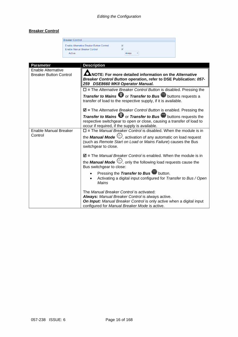
Breaker Control
Parameter Description
Enable Alternative Breaker Button Control NOTE: For more detailed information on the Alternative
Breaker Control Button operation, refer to DSE Publication: 057-259 DSE8660 MKII Operator Manual.
= The Alternative Breaker Control Button is disabled. Pressing the
Transfer to Mains or Transfer to Bus buttons requests a transfer of load to the respective supply, if it is available. = The Alternative Breaker Control Button is enabled. Pressing the
Transfer to Mains or Transfer to Bus buttons requests the respective switchgear to open or close, causing a transfer of load to occur if required, if the supply is available.
Enable Manual Breaker Control
= The Manual Breaker Control is disabled. When the module is in
the Manual Mode , activation of any automatic on load request (such as Remote Start on Load or Mains Failure) causes the Bus switchgear to close. = The Manual Breaker Control is enabled. When the module is in
the Manual Mode , only the following load requests cause the Bus switchgear to close:
• Pressing the Transfer to Bus button.
• Activating a digital input configured for Transfer to Bus / Open Mains
The Manual Breaker Control is activated: Always: Manual Breaker Control is always active. On Input: Manual Breaker Control is only active when a digital input configured for Manual Breaker Mode is active.

Editing the Configuration
Page 17 of 168 057-238 ISSUE: 6
2.2.2 CONFIGURABLE STATUS SCREENS Home Page
Parameter Description
Home Page
Mode: When no Navigation buttons are pressed for the duration of the Page Timer, the module’s display reverts back to show the Control Mode Page. The Configurable Status Screens are not displayed automatically but is still
accessible by manually pressing the Navigation buttons.
Instrumentation: When no Navigation buttons are pressed for the duration of the Page Timer, the module’s display scrolls through the Configurable Status Screens. Each of the Configurable Status Screens remains on the display for the duration of the Scroll Timer. The Control Mode page is not displayed
automatically but is still accessible by manually pressing the Navigation buttons.
Editing the Configuration
057-238 ISSUE: 6 Page 18 of 168
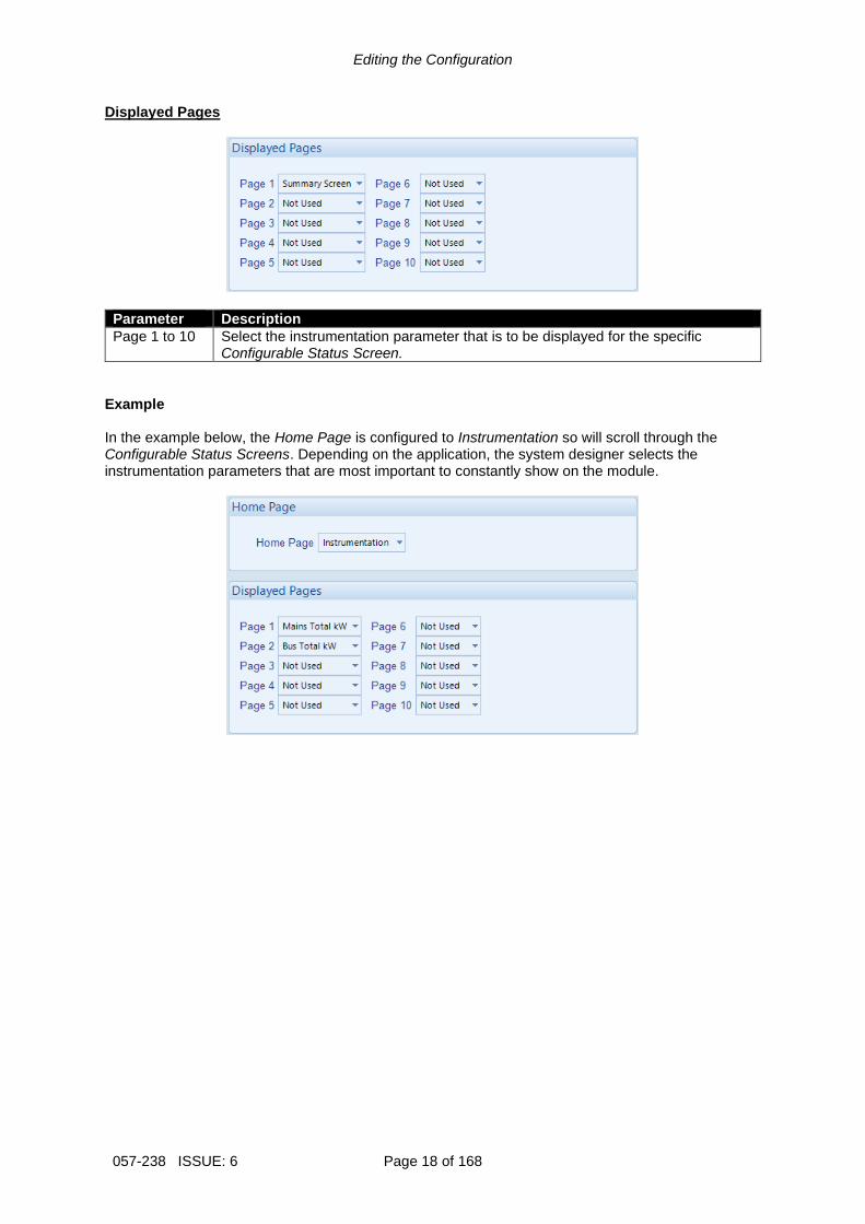
Displayed Pages
Parameter Description
Page 1 to 10 Select the instrumentation parameter that is to be displayed for the specific Configurable Status Screen.
Example In the example below, the Home Page is configured to Instrumentation so will scroll through the Configurable Status Screens. Depending on the application, the system designer selects the instrumentation parameters that are most important to constantly show on the module.
Editing the Configuration
Page 19 of 168 057-238 ISSUE: 6
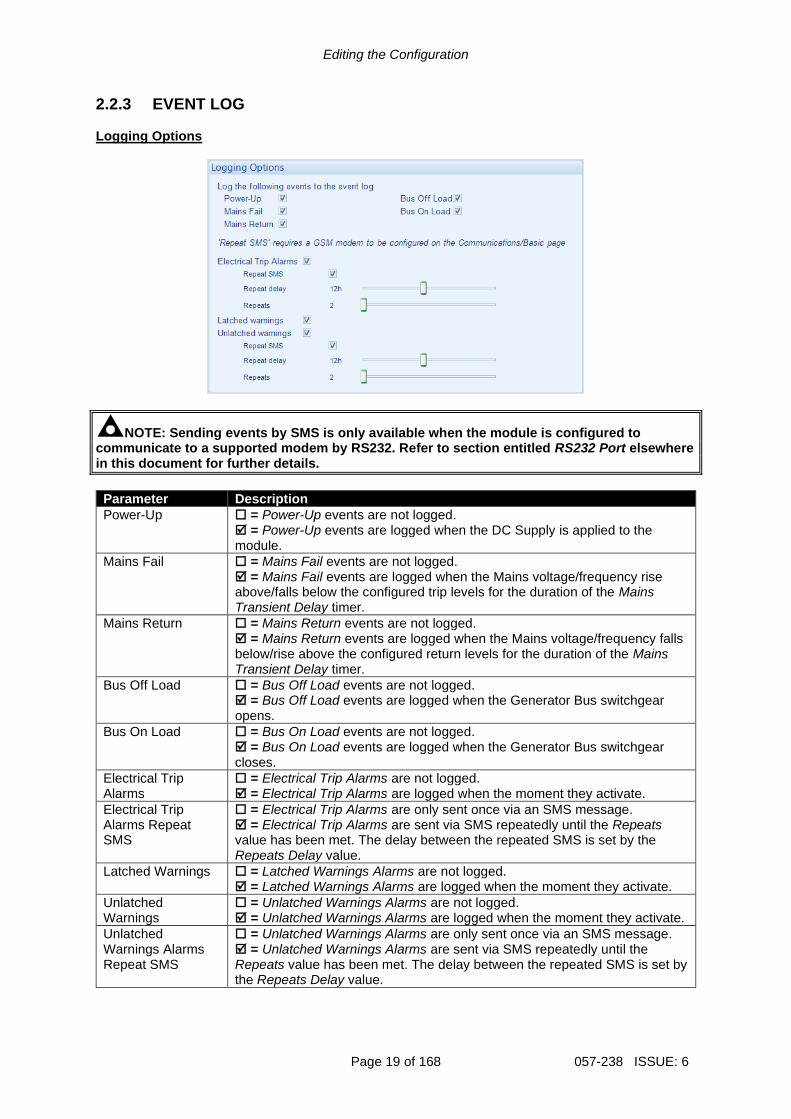
2.2.3 EVENT LOG Logging Options
NOTE: Sending events by SMS is only available when the module is configured to communicate to a supported modem by RS232. Refer to section entitled RS232 Port elsewhere in this document for further details.
Parameter Description
Power-Up = Power-Up events are not logged. = Power-Up events are logged when the DC Supply is applied to the module.
Mains Fail
= Mains Fail events are not logged. = Mains Fail events are logged when the Mains voltage/frequency rise above/falls below the configured trip levels for the duration of the Mains Transient Delay timer.
Mains Return
= Mains Return events are not logged. = Mains Return events are logged when the Mains voltage/frequency falls below/rise above the configured return levels for the duration of the Mains Transient Delay timer.
Bus Off Load = Bus Off Load events are not logged. = Bus Off Load events are logged when the Generator Bus switchgear opens.
Bus On Load = Bus On Load events are not logged. = Bus On Load events are logged when the Generator Bus switchgear closes.
Electrical Trip Alarms
= Electrical Trip Alarms are not logged. = Electrical Trip Alarms are logged when the moment they activate.
Electrical Trip Alarms Repeat SMS
= Electrical Trip Alarms are only sent once via an SMS message. = Electrical Trip Alarms are sent via SMS repeatedly until the Repeats value has been met. The delay between the repeated SMS is set by the Repeats Delay value.
Latched Warnings = Latched Warnings Alarms are not logged. = Latched Warnings Alarms are logged when the moment they activate.
Unlatched Warnings
= Unlatched Warnings Alarms are not logged. = Unlatched Warnings Alarms are logged when the moment they activate.
Unlatched Warnings Alarms Repeat SMS
= Unlatched Warnings Alarms are only sent once via an SMS message. = Unlatched Warnings Alarms are sent via SMS repeatedly until the Repeats value has been met. The delay between the repeated SMS is set by the Repeats Delay value.

Editing the Configuration
057-238 ISSUE: 6 Page 20 of 168
2.2.4 DATA LOGGING The Data Logging section is subdivided into smaller sections.
The module has the ability to record up to twenty parameters and is saved as a Data Log File to the module’s internal memory or an external USB storage device. If 20 parameters were configured to be logged, each with a Log Interval of 1 second, the length of each Data Log File would be 6 hours and 21 minutes. This time is extendable as the length of each Data Log File varies upon the number of selected parameters and their configured Log Interval. The module has the ability to store only one Data Log File to its internal memory. The number of Data Log Files increases when an external USB storage device is connected to the module’s USB Host port. The increased number of Data Log Files is dependent upon the size of the USB storage device connected. When using the maximum size USB storage device of 16 GB, the number of Data Log Files is increased to 8200. This results in a total Data Log length of 46 weeks, 2 days, 6 hours and 24 minutes (assuming 20 parameters were configured to be logged, each with a Log Interval of 1 second). The Data Logging is viewed using the Data Log Viewer application, which is accessed from the DSE Configuration Suite PC Software under the Tools menu.
Click to view / edit the section

Editing the Configuration
Page 21 of 168 057-238 ISSUE: 6
2.2.4.1 CONFIGURATION
Parameter Description
Logged Data Select the instrument required to be logged
Log Interval Select the logging interval of the data

Editing the Configuration
057-238 ISSUE: 6 Page 22 of 168
2.2.4.2 OPTIONS
Parameter Description
Only Log When Start is Requested
= The module logs data regardless if the Generator Bus has been requested to run. = The module only logs data when the Generator Bus has been requested to run.
Log to USB Drive = The module logs data to the modules internal memory. = The module logs data to an external USB memory device connect to the USB host socket on the module.
Keep Oldest Data = When the logging memory is full, the module overwrites the oldest data first with the new data. = When the logging memory is full, the module stops recording new data.

Editing the Configuration
Page 23 of 168 057-238 ISSUE: 6
2.3 DIGITAL INPUTS The Digital Inputs section is subdivided into smaller sections. Select the required section with the mouse.
2.3.1 DIGITAL INPUTS
Parameter Description
Function Select the input function to activate when the relevant terminal is energised. See section entitled Input Functions for details of all available functions
Polarity Select the digital input polarity: Close to Activate: the input function is activated when the relevant terminal is connected. Open to Activate: the input function is activated when the relevant terminal is disconnected.
Action NOTE: For details of these, see the section entitled Alarm Types
elsewhere in this document.
Select the type of alarm required from the list: Electrical Trip Indication Warning
Parameter descriptions are continued overleaf…
As this example shows a predefined function, these parameters are greyed out as they are not applicable.

Editing the Configuration
057-238 ISSUE: 6 Page 24 of 168
Parameter Description
Arming NOTE: For details of these, see the section entitled Alarm Arming
elsewhere in this document.
Select when the input becomes active: Active From Mains Parallel Always Never
LCD Display The text that is displayed on the module’s LCD when the input activates and generates an alarm.
Activation Delay This is used to give a delay on acceptance of the input. Useful for liquid level switches or to mask short term operations of the external switch device.

Editing the Configuration
Page 25 of 168 057-238 ISSUE: 6
2.3.2 INPUT FUNCTIONS Where a digital input is NOT configured as “user configured”, a selection is made from a list of predefined functions. The selections are as follows: Under the scope of IEEE 37.2, function numbers are also used to represent functions in microprocessor devices and software programs. Where the DSE input functions are represented by IEEE 37.2, the function number is listed below.
Function Description
Alarm Mute This input is used to silence the audible alarm from an external source, such as a remote mute switch.
Alarm Reset This input is used to reset any latched alarms from a remote location. It is also used to clear any latched warnings which may have occurred (if configured) without having to stop the Generator Bus.
Alternative Language Select
This input is used to instruct the module to display the alternative Language instead of the default module display language.
Auto Restore Inhibit IEEE 37.2 - 3 Checking Or Interlocking Relay
In the event of a remote start/Mains failure, the Generator Bus is instructed to start and take load. On removal of the remote start signal/Mains return the module continues to run the Generator Bus on load until the Auto Restore Inhibit input is removed. This input allows the controller to be fitted as part of a system where the restoration to Mains is controlled remotely or by an automated system.
Auto Run Inhibit IEEE 37.2 - 3 Checking Or Interlocking Relay
This input is used to provide an over-ride function to prevent the controller from starting/running the Generator Bus in the event of a remote start/scheduled run condition occurring. If this input is active and a remote start signal/scheduled run occurs the module does not give a start command to the Generator Bus or stops the Generator Bus if it is already running. If this input signal is then removed, the controller operates as if a remote start/scheduled run has occurred, starting and loading the Generator Bus. This function is used to give an ‘AND’ function so that a Generator Bus is only called to start/run if a remote start request and another condition exists which requires the Generator Bus to run. If the ‘Auto Run Inhibit’ signal becomes active while the Generator Bus is running, a controlled shutdown sequence begins. If the Generator Bus is running in a load demand scheme, this input takes priority and begins the controlled shutdown sequence, causing another Generator Bus to start (if available). This input does not prevent starting of the Generator Bus in MANUAL/TEST mode.
Auto Start Inhibit IEEE 37.2 - 3 Checking Or Interlocking Relay
This input is used to provide an over-ride function to prevent the controller from starting the Generator Bus in the event of a remote start/Mains out of limits condition occurring. If this input is active and a remote start signal/Mains failure occurs the module does not give a start command to the Generator Bus. If this input signal is then removed, the controller operates as if a remote start/Mains failure has occurred, starting and loading the Generator Bus. This function is used to give an ‘AND’ function so that a Generator Bus is only called to start if the Mains fails and another condition exists which requires the Generator Bus to run. If the ‘Auto start Inhibit’ signal becomes active once more it is ignored until the module has returned the Mains supply on load and shutdown. This input does not prevent starting of the Generator Bus in MANUAL mode.
Parameter descriptions are continued overleaf…

Editing the Configuration
057-238 ISSUE: 6 Page 26 of 168
Function Description
Auxiliary Mains Fail
The module monitors the incoming single or three phase supply for Over voltage, Under Voltage, Over Frequency or Under frequency. It may be required to monitor a different Mains supply or some aspect of the incoming Mains not monitored by the controller (such as a G59 or G99 Mains decoupling relay). If the devices providing this additional monitoring are connected to operate this input, the controller operates as if the incoming Mains supply has fallen outside of limits, the Generator Bus is instructed to start and take the load if not already running. Removal of the input signal causes the module to act if the Mains has returned to within limits providing that the Mains sensing also indicates that the Mains is within limits.
Bus Closed Auxiliary IEEE 37.2 - 3 Checking or Interlocking Relay
This input is used to provide feedback to allow the module to give true indication of the contactor or circuit breaker switching status. It must be connected to the Bus load switching device auxiliary contact.
Bus Load Inhibit IEEE 37.2 - 52 AC Circuit Breaker
NOTE: This input only operates to control the Bus switchgear if the module load switching logic is attempting to load the Bus.
This input is used to prevent the module from loading the Generator Bus. If the Generator Bus is already on load, activating this input causes the module to unload the Generator Bus without ramping. Removing the input allows the Generator Bus to be loaded again.
Clear Mains Decoupling Alarms
This input is used to reset the module following a Mains Decoupling Alarm (ROCOF, Vector Shift, Mains Voltage Alarm, Mains Frequency Alarm). The input must switch from inactive to active to reset the trip, it is not to be left permanently active.
EJP1 For the French EJP (Effacement Jours de Pointe) tariff system. This input is functionally identical to Remote Start Off Load. When this input is active, operation is similar to the ‘Remote Start on load’ function except that the Generator Bus is not instructed to take the load. This function is also used where the Generator Bus only run is required e.g. for exercise.
EJP2 For the French EJP (Effacement Jours de Pointe) tariff system. This input is functionally identical to Remote Start On Load. In auto mode, the module performs the start sequence and transfers load to the Generator Bus. In Manual mode, the load is transferred to the Generator Bus if the Generator Bus is already running, however in manual mode, this input does not generate start/stop requests of the generate Bus.
Enable Power Mode 1 Constant Power (Default)
This input is used to instruct the module to switch to Power Mode 1 Constant Power (Default)
Enable Power Mode 2 Frequency-Power
This input is used to instruct the module to switch to Power Mode 2 Frequency-Power
Enable Power Mode 3 Voltage-Power
This input is used to instruct the module to switch to Power Mode 3 Voltage-Power
Enable Power Mode 1 Constant Power Factor
This input is used to instruct the module to switch to Power Mode 1 Constant Power Factor
Enable Reactive Mode 2 Voltage-Reactive Power
This input is used to instruct the module to switch to Reactive Mode 2 Voltage-Reactive Power
Enable Reactive Mode 3 Power-Power Factor
This input is used to instruct the module to switch to Reactive Mode 3 Power-Power Factor
Enable Reactive Mode 4 Constant Reactive Power (Default)
This input is used to instruct the module to switch to Reactive Mode 4 Constant Reactive Power (Default)
Parameter descriptions are continued overleaf…

Editing the Configuration
Page 27 of 168 057-238 ISSUE: 6
Function Description
External Panel Lock NOTE: External control sources (i.e. Simulate Start Button)
are not affected by the external panel lock input and continue to operate normally.
This input is used to provide security to the installation. When the External Panel lock input is active, the module does not respond to operation of the Mode select or Start buttons. This allows the module to be placed into a specific mode (such as Auto) and then secured. The operation of the module is not affected, and the operator is still able to view the various instrumentation pages etc. (Front panel configuration access is still possible while the system lock is active).
Inhibit Remote Start of 8610
This input is used to provide a mean of disabling all start commands over the MSC link to the DSExx10 modules, including in the event of a Mains failure.
Inhibit Retransfer To Mains IEEE 37.2 - 3 Checking Or Interlocking Relay
When active, the input prevents the load from being transferred back to the Mains supply, only in the event of a Generator Bus failure. This is used in peak lopping systems where the cost of using the Mains to supply the load is so prohibitive that the customer does not want to transfer back to the Mains supply.
Inhibit Scheduled Run IEEE 37.2 – 3 Checking Or Interlocking Relay
This input is used to provide a mean of disabling a scheduled run.
Inhibit SMS Remote Start This input is used to provide a means of disabling remote starts by SMS
Keep Control of 8610s This input is used to keep control over the DSExx10 modules and their generators, preventing another DSExx60 or DSExx80 taking control for synchronising and parallel operation.
Lamp Test This input is used to provide a test facility for the front panel indicators fitted to the module. When the input is activated all LEDs illuminate.
Mains Closed Auxiliary IEEE 37.2 - 3 Checking or Interlocking Relay
This input is used to provide feedback to allow the module to give true indication of the contactor or circuit breaker switching status. It must be connected to the Mains load switching device auxiliary contact.
Mains Load Inhibit IEEE 37.2 - 52 AC Circuit Breaker NOTE: This input only operates to control the Mains
switchgear if the module load switching logic is attempting to load the mains.
This input is used to prevent the module from loading the mains. If the Mains is already on load, activating this input causes the module to unload the Mains without ramping. Removing the input allows the Mains to be loaded again.
Manual Breaker Mode When breaker control is set to Active On Input, this input is used to activate the Manual Breaker Control.
Manual Restore Contact This input is used to manually allow back-sync to the Mains without removing the Auto-Restore Inhibit input.
Parameter descriptions are continued overleaf…

Editing the Configuration
057-238 ISSUE: 6 Page 28 of 168
Function Description
MSC Alarms Inhibit
NOTE: The MSC Old Version alarm is not inhibited when this input is active.
If this input is active, all MSC failure related alarms are inhibited from activating even if the fault is active.
Paralleling Inhibit IEEE 37.2 - 3 Checking Or Interlocking Relay
This input is used to prevent the Generator Bus from running in parallel with the Mains supply and in turn, forces a break transfer to occur. If the input becomes active while in parallel, the transfer is completed and paralleling ends.
Remote Start Dead Bus Synchronising NOTE: For further details, refer to the section entitled
Advanced Options elsewhere in this document.
This input is used to enable a Dead Bus Synchronising start and must be used in conjunction with another starting signal such as Remote Start on Load.
Remote Start In Island Mode
When in Auto Mode, the module performs the start sequence and transfer the load to the Generator Bus. The Mains switchgear is left open and the Generator Bus runs in island mode. In Manual Mode, the load is transferred to the Generator Bus if it is already running and available; however in Manual Mode, this input does not generate start/stop requests to the Generator Bus.
Remote Start Off Load If this input is active, operation is similar to the ‘Remote Start on load’ function except that the Generator Bus is not instructed to take the load. This function is used where the Generator Bus only run is required e.g. for exercise.
Remote Start On Load When in auto mode, the module performs the start sequence and places the Generator Bus in parallel with the mains. In Manual mode, the Generator Bus is placed in parallel with the Mains if it was already running; however in manual mode, this input does not generate start/stop requests.
Simulate Auto Button NOTE: If a call to start is present when AUTO MODE is
entered, the starting sequence begins. Call to Start comes from a number of sources depending upon module type and configuration and includes (but is not limited to) : Remote start input present, Mains failure, Scheduled run, Auxiliary Mains failure input present, Telemetry start signal from remote locations.
This input mimic’s the operation of the ‘Auto’ button and is used to provide a remotely located Auto mode push button.
Simulate Lamp Test / Alarm Mute Button
This input is used to provide a test facility for the front panel indicators fitted to the module. When the input is activated all LED’s illuminate. The input also serves a second function, in that it also provides a mute signal to silence the audible alarm. The input is recognised by the module as though it was the Push button on the module itself being operated.
Simulate Mains Available. This function is provided to override the module’s internal monitoring function. If this input is active, the module does not respond to the state of the incoming AC Mains supply.
Simulate Manual Button
This input mimic’s the operation of the ‘Manual’ button and is used to provide a remotely located Manual mode push button.
Parameter descriptions are continued overleaf…

Editing the Configuration
Page 29 of 168 057-238 ISSUE: 6
Function Description
Simulate Start Button
This input mimic’s the operation of the ‘Start’ button and is used to provide a remotely located start push button.
Simulate Stop Button
This input mimic’s the operation of the ‘Stop’ button and is used to provide a remotely located stop/reset push button.
Simulate Test On Load Button
This input mimics the operation of the ‘Test’ button and is used to provide a remotely located Test on load mode push button.
Stop and Panel Lock Combined function input that instructs the module to enter STOP mode and also perform the Panel Lock function. Once the input is active, the module does not respond to operation of the mode select or start buttons. The operator is still able to view the various instrumentation pages etc. (Front panel configuration access is still possible while the system lock is active).
Telemetry Panel Lock Once the input is active, the module does not respond to mode changes or breaker control by telemetry. The operator is still able to control and view the various instrumentation pages through the front panel buttons.
Transfer To Bus / Open Mains IEEE 37.2 - 52 AC Circuit Breaker
This input is used to transfer the load to the Generator Bus when running in Manual Mode. Once synchronised, the Generator Bus and Mains are paralleled. The second press of the button causes the Generator Bus to take full load and open the Mains switchgear.
Transfer to Mains / Open Bus IEEE 37.2 - 52 AC Circuit Breaker
This input is used to transfer the load to the Mains when running in Manual Mode. Once synchronised, the Generator Bus and Mains are paralleled. The second press of the button causes the Mains to take full load and open the Generator Bus switchgear.

Editing the Configuration
057-238 ISSUE: 6 Page 30 of 168
2.4 OUTPUTS The Outputs section is subdivided into smaller sections. Select the required section with the mouse.
2.4.1 DIGITAL OUTPUTS
Parameter Description
Source Select the output source to control the state of the output See section entitled Output Sources for details of all available functions
Polarity Select the digital output polarity: De-Energise: When the output source is true, the output deactivates. Energise: When the output source is true, the output activates.
These labels match the typical wiring diagram

Editing the Configuration
Page 31 of 168 057-238 ISSUE: 6
2.4.2 VIRTUAL LEDS The virtual LEDs provide a configuration of ‘status’ items. These items are not available for viewing on the module but are seen in the SCADA section of the PC software, or read by third party systems (i.e. BMS or PLCs) using the ModBus protocol.
Parameter Description
Source Select the output source to control the state of the output See section entitled Output Sources for details of all available functions
Polarity Select the digital input polarity: Lit: When the output source is true, the virtual LED activates Unlit: When the output source is true, the virtual LED deactivates.

Editing the Configuration
057-238 ISSUE: 6 Page 32 of 168
2.4.3 OUTPUT SOURCES The list of output sources available for configuration of the module digital outputs. Under the scope of IEEE 37.2, function numbers is also used to represent functions in microprocessor devices and software programs. Where the DSE output functions is represented by IEEE 37.2, the function number is listed below.
Output Source Activates… Is Not Active….
Not Used The output does not change state (Unused)
1 Constant Power Factor Mode
Active when the Reactive Mode 1 Constant Power Factor is selected.
1 Constant Power Mode (Default)
Active when the Power Mode 1 Constant Power (Default) is selected.
2 Frequency-Power Mode Active when the Power Mode 2 Frequency Power is selected.
2 Voltage-Reactive Power Mode
Active when the Reactive Mode 2 Voltage Reactive Power is selected.
3 Power-Power Factor Mode
Active when the Reactive Mode 3 Power Power Factor is selected.
3 Voltage-Power Mode Active when the Power Mode 3 Voltage Power is selected.
4 Constant Reactive Power Mode (Default)
Active when the Reactive Mode 4 Constant Reactive Power (Default) is selected.
8660 Controls 8610s Active when the module is controlling the DSExx10 modules and their generators, preventing another DSExx60 or DSExx80 taking control for synchronising and parallel operation.
Alarm Mute This input is used to silence the audible alarm from an external source such as a remote mute switch.
Alarm Reset This input is used to reset any latched alarms from a remote location. It is also used to clear any latched warnings which may have occurred (if configured) without having to stop the Generator Bus.
Alternative Language Selected
Active when the configured Alternative Language Select digital input is active
Audible Alarm IEEE 37.2 – 74 Alarm Relay
Use this output to activate an external sounder or external alarm indicator. Operation of the Mute pushbutton resets this output once activated
Inactive if no alarm condition is active or if the Mute pushbutton was pressed
Auto Restore Inhibit Active when the Auto Restore Inhibit digital input is active.
Auto Run Inhibited Active when the Auto Run Inhibit function is active
Auto Start Inhibit Active when the Auto-Start Inhibit function is active
Auxiliary Mains Failure Active when the Auxiliary Mains Failure input function is active
Battery High Voltage IEEE 37.2 – 59 DC Overvoltage Relay
This output indicates that a Battery Over voltage alarm has occurred
Inactive when battery voltage is not High
Battery Low Voltage IEEE 37.2 – 27 DC Undervoltage Relay
This output indicates that a Battery Under Voltage alarm has occurred.
Inactive when battery voltage is not Low
Bus And Mains In Parallel This output is active whenever the Bus and Mains are in parallel.
Bus Asymmetry High IEEE 37.2 – 59 Overvoltage Relay
Active when the Bus Asymmetry Alarm is active
Bus Closed Auxiliary Active when the Bus Closed Auxiliary input is active
Bus Failed To Close IEEE 37.2 - 48 Incomplete Sequence Relay
This output source is intended to be used to indicate a failure of the Bus contactor or breaker. It is only used if the module is configured to use ‘Bus Closed Auxiliary’ feedback.
Parameter descriptions are continued overleaf…

Editing the Configuration
Page 33 of 168 057-238 ISSUE: 6
Output Source Activates… Is Not Active….
Bus Failed To Open IEEE 37.2 - 48 Incomplete Sequence Relay
This output source is intended to be used to indicate a failure of the Bus contactor or breaker. It is only used if the module is configured to use ‘Bus Closed Auxiliary’ feedback.
Bus Live This output indicates that a voltage has been detected on the Generator Bus. Once the voltage on the Generator Bus is detected above the “Dead Bus relay setting”, it is no longer considered a ‘dead-bus’ and the Mains needs to synchronise with the Bus.
Bus Load Inhibit Active when the digital input Bus Load Inhibit is active.
Bus Negative Sequence Voltage High IEEE 37.2 – 47 Phase-Sequence Or Phase Balance Voltage Relay
Active when the Bus Negative Sequence Voltage Alarm is active
Bus Phase Rotation Alarm
This output indicates that the module has detected a phase sequence error on the Bus.
Bus Positive Sequence Voltage Low IEEE 37.2 – 47 Phase-Sequence Or Phase Balance Voltage Relay
Active when the Bus Positive Sequence Alarm is active
Bus Zero Sequence Voltage High IEEE 37.2 – 47 Phase-Sequence Or Phase Balance Voltage Relay
Active when the Bus Zero Sequence Alarm is active
Calling For Scheduled Run
Active during a Scheduled Run request from the inbuilt Scheduler.
Charger ID0, ID1, ID2, ID3 Common Shutdown
Active when the DSE module detects a Common Shutdown alarm on the relevant DSE Intelligent Charger connected to the DSEnet with the respective ID.
Charger ID0, ID1, ID2, ID3 Common Warning
Active when the DSE module detects a Common Warning alarm on the relevant DSE Intelligent Charger connected to the DSEnet with the respective ID.
Check Sync IEEE 37.2 – 25 Synchronising Or Synchronising Check Relay
Indicates that the internal check synchroscope has determined that the supplies are in sync.
Clear Mains Decoupling Active when the Clear Mains Decoupling Alarms digital input is active.
Clock Pulse Also called ‘heartbeat’, it activates and deactivates every few milliseconds to indicate that the module is powered up. It stops energising during write configuration to the module.
Close Bus Output IEEE 37.2 – 52 AC Circuit Breaker
Used to control the Generator Bus load switching device. Whenever the module selects the Generator Bus to be on load this control source is activated.
Inactive whenever the Generator Bus is not required to be on load
Close Bus Output Pulse IEEE 37.2 – 52 AC Circuit Breaker
Used to control the Generator Bus load switching device. Whenever the module selects the Generator Bus to be on load this control source is activated for the duration of the Breaker Close Pulse timer, after which it becomes inactive again.
Close Mains Output IEEE 37.2 – 52 AC Circuit Breaker
Used to control the Mains load switching device. Whenever the module selects the Mains to be on load this control source is activated.
Inactive whenever the Mains is not required to be on load
Parameter descriptions are continued overleaf…

Editing the Configuration
057-238 ISSUE: 6 Page 34 of 168
Output Source Activates… Is Not Active….
Close Mains Output Pulse IEEE 37.2 – 52 AC Circuit Breaker
Used to control the load switching device. Whenever the module selects the Mains to be on load this control source is activated for the duration of the Breaker Close Pulse timer, after which it becomes inactive again.
Closed To Mains State Active when the status of the Mains breaker is closed.
Combined Mains Failure Active when the Mains supply is out of limits OR the input for Auxiliary Mains Failure is active
Combined Remote Start Request
Indicates that a remote start request is active.
Common Alarm Active when one or more alarms (of any type) are active
The output is inactive when no alarms are present
Common Electrical Trip Active when one or more Electrical Trip alarms are active
The output is inactive when no shutdown alarms are present
Common Mains Decoupling Alarm
Indicates 1 or more of the decoupling alarm have activated
Common Warning Active when one or more Warning alarms are active
The output is inactive when no warning alarms are present
Data Logging Active Active when data is being logged Inactive when: Data logging is disabled The Generator Bus is at rest and the option Only Log When Start is Requested is enabled The internal memory of the module becomes full and the option Keep Oldest Data is enabled
DC Power On Active when DC power is supplied to the module
Dead Bus Synchronise Enabled
Active when Dead Bus Synchronising is enabled.
Dead Bus Synchronise In Progress
Active when the Generator Bus is running dead Bus synchronising.
Digital Input A, B, C, D, E, F, G H, I, J, K & L
Active when the relevant digital input is active
Display Heater Fitted and On
Active when the display heater is on
EJP1 / EJP2 Active when an input configured for EJP1 or EJP2 is active
Expansion 2130 Address 0 to 3 Analogue Input E to H (Digital)
Active when the relevant analogue input on the relevant DSE2130 is configured as a digital input and is active
Expansion 2130 Address 0 to 3 Analogue Input A to D (Digital)
Active when the relevant digital input on the relevant DSE2130 is active
Expansion 2130 Address 0 to 3 Input E to H High Shutdown
Active when the relevant analogue input on the relevant DSE2130 high alarm is active
Expansion 2130 Address 0 to 3 Input E to H High Warning
Active when the relevant analogue input on the relevant DSE2130 high pre-alarm is active
Expansion 2130 Address 0 to 3 Input E to H Low Shutdown
Active when the relevant analogue input on the relevant DSE2130 low alarm is active
Parameter descriptions are continued overleaf…

Editing the Configuration
Page 35 of 168 057-238 ISSUE: 6
Output Source Activates… Is Not Active….
Expansion 2130 Address 0 to 3 Input E to H Low Warning
Active when the relevant analogue input on the relevant DSE2130 low pre-alarm is active
Expansion 2131 Address 0 to 3 Analogue Input A to J (Digital)
Active when the relevant analogue input on the relevant DSE2131 is configured as a digital input and is active
Expansion 2131 Address 0 to 3 Input A to J High Shutdown
Active when the relevant analogue input on the relevant DSE2131 high alarm is active
Expansion 2131 Address 0 to 3 Input A to J High Warning
Active when the relevant analogue input on the relevant DSE2131 high pre-alarm is active
Expansion 2131 Address 0 to 3 Input A to J Low Shutdown
Active when the relevant analogue input on the relevant DSE2131 low alarm is active
Expansion 2131 Address 0 to 3 Input A to J Low Warning
Active when the relevant analogue input on the relevant DSE2131 low pre-alarm is active
Expansion 2133 Address 0 to 3 Input A to H High Shutdown
Active when the relevant analogue input on the relevant DSE2133 high alarm is active
Expansion 2133 Address 0 to 3 Input A to H High Warning
Active when the relevant analogue input on the relevant DSE2133 high pre-alarm is active
Expansion 2133 Address 0 to 3 Input A to H Low Shutdown
Active when the relevant analogue input on the relevant DSE2133 low alarm is active
Expansion 2133 Address 0 to 3 Input A to H Low Warning
Active when the relevant analogue input on the relevant DSE2133 low pre-alarm is active
Fail to Synchronise IEEE 37.2 - 48 Incomplete Sequence Relay
Becomes active if the module fails to synchronise after the fail to sync timer.
Fault Ride Through Event Becomes active during a Fault Ride Through event, the module generates a Warning alarm.
Becomes inactive when there is no Fault Ride Through event.
Inhibit Retransfer To Mains
Indicates that the load is prevented from being transferred back to the Mains supply in the event of a Generator Bus failure. This is used in peak lopping systems where the cost of using the Mains to supply the load is so prohibitive that the customer does not want to transfer back to the Mains supply.
Inhibit Scheduled Run Active when the Inhibit Scheduled run input is active
Inhibit SMS Start Active when the input Inhibit SMS Start input is active
Insufficient Capacity Available
Indicates that during parallel operation, it has been determined that the Generator Bus is not capable of providing the power configured to deliver.
Interlock Override Activates when the Synchronising Delay timer begins. Used to disable external interlock between the Mains and Bus switchgear when the supplies are requested in to be in parallel.
De-activates when the Interlock Override Delay timer expires after the changeover has completed.
Keep Control Of 8610s Active when the Keep Control of 8610s input is active
Lamp Test Active when the lamp test is activated by a digital input or by pressing the Mute/Lamp Test control button
Parameter descriptions are continued overleaf…

Editing the Configuration
057-238 ISSUE: 6 Page 36 of 168
Output Source Activates… Is Not Active….
Mains Asymmetry High IEEE 37.2 – 59 Overvoltage Relay
Active when the Mains Asymmetry Alarm is active
Mains Closed Aux Active when the Mains Closed Auxiliary input is active
Mains Decoupling High Frequency Stage 1,2
This output indicates that the relevant Mains decoupling high frequency alarm has been triggered.
Mains Decoupling High Voltage Stage 1,2
This output indicates that the relevant Mains decoupling high voltage alarm has been triggered.
Mains Decoupling Low Frequency Stage 1,2
This output indicates that the relevant Mains decoupling low frequency alarm has been triggered.
Mains Decoupling Low Voltage Stage 1,2
This output indicates that the relevant Mains decoupling low voltage alarm has been triggered.
Mains Failed To Close This output indicates the Mains breaker failed to close
Mains Failed To Open This output indicates the Mains breaker failed to open
Mains Failure IEEE 37.2 - 81 Frequency Relay IEEE 37.2 – 27AC Under Voltage Relay IEEE 37.2 – 59AC Over Voltage Relay
The output indicates that one or more of the module’s sources of determining Mains failure is active. The output is inactive when the Mains supply is healthy
Mains High Frequency IEEE 37.2 - 81 Frequency Relay
Active when the Mains frequency exceeds the High Frequency setting
Mains High Voltage IEEE 37.2 – 59AC Overvoltage Relay
Active when the Mains voltage exceeds the High Voltage setting
Mains Load Inhibited
Active when the Mains Load Inhibit digital input is active
Mains Low Frequency IEEE 37.2 - 81 Frequency Relay
Active when the Mains frequency falls below the Low Frequency setting
Mains Low Voltage IEEE 37.2 – 27AC Under Voltage Relay
Active when the Mains voltage falls below the Low Voltage setting
Mains Negative Sequence Voltage High IEEE 37.2 – 47 Phase-Sequence Or Phase Balance Voltage Relay
Active when the Mains Negative Sequence Voltage Alarm is active
Mains Phase Rotation Alarm IEEE 37.2 – 47 Phase-Sequence Or Phase Balance Voltage Relay
Active when the Mains phase rotation alarm is active
Mains Positive Sequence Voltage Low IEEE 37.2 – 47 Phase-Sequence Or Phase Balance Voltage Relay
Active when the Mains Positive Sequence Alarm is active
Mains ROCOF Indicates that the ROCOF protection (when in parallel with mains) has triggered.
Mains Vector Shift Indicates that the Vector Shift protection (when in parallel with mains) has triggered.
Mains Zero Sequence Voltage High IEEE 37.2 – 47 Phase-Sequence Or Phase Balance Voltage Relay
Active when the Mains Zero Sequence Alarm is active
Minimum Sets Not Reached
Indicates that the required number of generators that are closed on to the Bus has not been met to allow the module to close the Bus switchgear.
MSC Alarms Disabled Active when the MSC Alarms Inhibit digital input function is active.
Parameter descriptions are continued overleaf…
Editing the Configuration
Page 37 of 168 057-238 ISSUE: 6
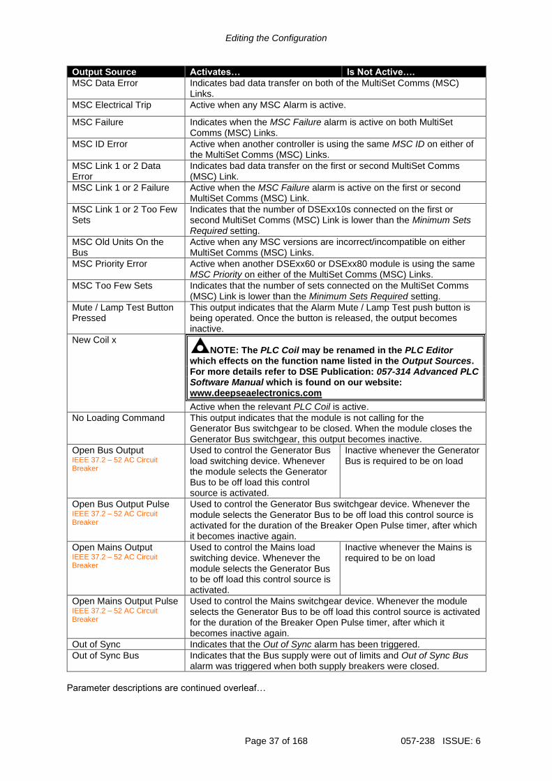
Output Source Activates… Is Not Active….
MSC Data Error Indicates bad data transfer on both of the MultiSet Comms (MSC) Links.
MSC Electrical Trip Active when any MSC Alarm is active.
MSC Failure Indicates when the MSC Failure alarm is active on both MultiSet Comms (MSC) Links.
MSC ID Error Active when another controller is using the same MSC ID on either of the MultiSet Comms (MSC) Links.
MSC Link 1 or 2 Data Error
Indicates bad data transfer on the first or second MultiSet Comms (MSC) Link.
MSC Link 1 or 2 Failure Active when the MSC Failure alarm is active on the first or second MultiSet Comms (MSC) Link.
MSC Link 1 or 2 Too Few Sets
Indicates that the number of DSExx10s connected on the first or second MultiSet Comms (MSC) Link is lower than the Minimum Sets Required setting.
MSC Old Units On the Bus
Active when any MSC versions are incorrect/incompatible on either MultiSet Comms (MSC) Links.
MSC Priority Error Active when another DSExx60 or DSExx80 module is using the same MSC Priority on either of the MultiSet Comms (MSC) Links.
MSC Too Few Sets Indicates that the number of sets connected on the MultiSet Comms (MSC) Link is lower than the Minimum Sets Required setting.
Mute / Lamp Test Button Pressed
This output indicates that the Alarm Mute / Lamp Test push button is being operated. Once the button is released, the output becomes inactive.
New Coil x NOTE: The PLC Coil may be renamed in the PLC Editor
which effects on the function name listed in the Output Sources. For more details refer to DSE Publication: 057-314 Advanced PLC Software Manual which is found on our website: www.deepseaelectronics.com
Active when the relevant PLC Coil is active.
No Loading Command This output indicates that the module is not calling for the Generator Bus switchgear to be closed. When the module closes the Generator Bus switchgear, this output becomes inactive.
Open Bus Output IEEE 37.2 – 52 AC Circuit Breaker
Used to control the Generator Bus load switching device. Whenever the module selects the Generator Bus to be off load this control source is activated.
Inactive whenever the Generator Bus is required to be on load
Open Bus Output Pulse IEEE 37.2 – 52 AC Circuit Breaker
Used to control the Generator Bus switchgear device. Whenever the module selects the Generator Bus to be off load this control source is activated for the duration of the Breaker Open Pulse timer, after which it becomes inactive again.
Open Mains Output IEEE 37.2 – 52 AC Circuit Breaker
Used to control the Mains load switching device. Whenever the module selects the Generator Bus to be off load this control source is activated.
Inactive whenever the Mains is required to be on load
Open Mains Output Pulse IEEE 37.2 – 52 AC Circuit Breaker
Used to control the Mains switchgear device. Whenever the module selects the Generator Bus to be off load this control source is activated for the duration of the Breaker Open Pulse timer, after which it becomes inactive again.
Out of Sync Indicates that the Out of Sync alarm has been triggered.
Out of Sync Bus Indicates that the Bus supply were out of limits and Out of Sync Bus alarm was triggered when both supply breakers were closed.
Parameter descriptions are continued overleaf…
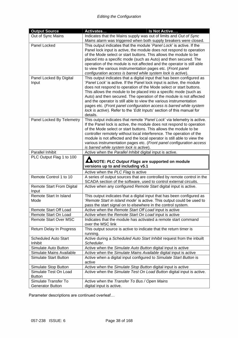
Editing the Configuration
057-238 ISSUE: 6 Page 38 of 168
Output Source Activates… Is Not Active….
Out of Sync Mains Indicates that the Mains supply was out of limits and Out of Sync Mains alarm was triggered when both supply breakers were closed.
Panel Locked This output indicates that the module ‘Panel Lock’ is active. If the Panel lock input is active, the module does not respond to operation of the Mode select or start buttons. This allows the module to be placed into a specific mode (such as Auto) and then secured. The operation of the module is not affected and the operator is still able to view the various instrumentation pages etc. (Front panel configuration access is barred while system lock is active).
Panel Locked By Digital Input
This output indicates that a digital input that has been configured as ‘Panel Lock’ is active. If the Panel lock input is active, the module does not respond to operation of the Mode select or start buttons. This allows the module to be placed into a specific mode (such as Auto) and then secured. The operation of the module is not affected and the operator is still able to view the various instrumentation pages etc. (Front panel configuration access is barred while system lock is active). Refer to the ‘Edit Inputs’ section of this manual for details.
Panel Locked By Telemetry This output indicates that remote ‘Panel Lock’ via telemetry is active. If the Panel lock is active, the module does not respond to operation of the Mode select or start buttons. This allows the module to be controller remotely without local interference. The operation of the module is not affected and the local operator is still able to view the various instrumentation pages etc. (Front panel configuration access is barred while system lock is active).
Parallel Inhibit Active when the Parallel Inhibit digital input is active.
PLC Output Flag 1 to 100 NOTE: PLC Output Flags are supported on module
versions up to and including v5.1
Active when the PLC Flag is active
Remote Control 1 to 10 A series of output sources that are controlled by remote control in the SCADA section of the software, used to control external circuits.
Remote Start From Digital Input
Active when any configured Remote Start digital input is active.
Remote Start In Island Mode
This output indicates that a digital input that has been configured as ‘Remote Start in island mode’ is active. This output could be used to pass the start signal on to elsewhere in the control system.
Remote Start Off Load Active when the Remote Start Off Load input is active
Remote Start On Load Active when the Remote Start On Load input is active
Remote Start Over MSC Indicates that the module has activated a remote start command over the MSC link
Return Delay In Progress This output source is active to indicate that the return timer is running.
Scheduled Auto Start Inhibit
Active during a Scheduled Auto Start Inhibit request from the inbuilt Scheduler.
Simulate Auto Button Active when the Simulate Auto Button digital input is active
Simulate Mains Available Active when the Simulate Mains Available digital input is active
Simulate Start Button Active when a digital input configured to Simulate Start Button is active
Simulate Stop Button Active when the Simulate Stop Button digital input is active
Simulate Test On Load Button
Active when the Simulate Test On Load Button digital input is active.
Simulate Transfer To Generator Button
Active when the Transfer To Bus / Open Mains digital input is active.
Parameter descriptions are continued overleaf…

Editing the Configuration
Page 39 of 168 057-238 ISSUE: 6
Output Source Activates… Is Not Active….
Simulate Transfer To Mains Button
Active when the Transfer To Mains / Open Bus digital input is active.
SMS Remote Start in Island Mode
Active when the module receives an SMS message to start and run in island mode
SMS Remote Start Off Load
Active when the module receives an SMS message to start and run off load
SMS Remote Start On Load
Active when the module receives an SMS message to start and run load
Stop and Panel lock Active when the Stop And Panel Lock digital input is active
Stop Button Pressed This output indicates that the stop pushbutton is being operated. Once the button is released, the output becomes inactive.
Sufficient Sets Available This output indicates that there are sufficient generators available on the Bus.
Synching Enabled This output indicates that the synchronisation feature has been enabled.
System Healthy This output indicates that the module is in Auto Mode and there are no alarms present.
System in Auto Mode Active when Auto mode is selected
System in Manual Mode Active when Manual mode is selected
System in Stop Mode Active when Stop mode is selected
System in Test Mode Active when Test mode is selected
Telemetry Active Active when the communication port is live and for a short time after transmission stops. Used as a relay or LED source.
Telemetry Data Active Active when data is being transmitted. This output changes continuously state (flash) upon data transfer. Normally used as an LED source rather than a relay source as the signal flashes repeatedly. For a similar source more suited to drive a relay, see Telemetry Active.
Telemetry Panel Lock Active when the Telemetry Panel Lock digital input is active
Telemetry Start in Auto Mode
Active when a Remote Start Request is sent over by communication
Trip Bus in Parallel This output indicates that the module has been forced to remove the generators Bus from its load to pass control of the generators over to another DSExx60 that has detected a Mains failure. This only occurs if the Enable Forced Peak Lop Inhibit has been enabled.
Waiting For Manual Restore IEEE 37.2 – 3 Checking or Interlocking Relay
Becomes active when the Generator Bus is on load and the Mains supply is healthy but an input configured to Manual Restore is active. This is used to signal to an operator that action is required before the load transfers back to the Mains supply.

Editing the Configuration
057-238 ISSUE: 6 Page 40 of 168
2.5 TIMERS Many timers are associated with alarms. Where this occurs, the timer for the alarm is located on the same page as the alarm setting. Timers not associated with an alarm are located on the timers page. The Timers page is subdivided into smaller sections. Select the required section with the mouse.
2.5.1 START TIMERS Start Delay
Timer Description
Remote Start Off Load
The amount of time delay before starting in AUTO mode. This timer is activated upon the Remote Start Off Load command being issued. Typically this timer is applied to prevent starting upon fleeting start signals.
Remote Start On Load
The amount of time delay before starting in AUTO mode. This timer is activated upon the Remote Start On Load command being issued. Typically this timer is applied to prevent starting upon fleeting start signals.
Telemetry Start The amount of time delay before starting in AUTO mode. This timer is activated upon a Remote Start command being received from a MODBUS master. Typically this timer is applied to prevent starting upon fleeting start signals.
Mains Fail
The amount of time delay before starting in AUTO mode. This timer is activated upon a Mains failure detection.
Mains Transient Delay
Used to give a delay between sensing Mains failure and acting upon it. This is used to prevent dropouts of the Mains load switch and operation of the system due to Mains supply transient conditions.
Click and drag to change the setting. Timers increment in steps of 1 second up to one minute, then in steps of 30 seconds up to 30minutes, then in steps of 30 minutes thereafter (where allowed by the limits of the timer).

Editing the Configuration
Page 41 of 168 057-238 ISSUE: 6
2.5.2 LOAD / STOPPING TIMERS Load Timers
Timer Description
Transfer Time / Load Delay
The delay time between the Mains switchgear opening to the Bus switchgear closing.
Breaker Close Pulse The amount of time that Breaker Close Pulse signal is present when the request to close the load switch is given.
Breaker Trip Pulse The amount of time that Breaker Open Pulse signal is present when the request to open the load switch is given.
Bus Close Delay The time from the Mains breaker becoming open to the Bus Breaker being requested to close. This is used to allow the Generator Bus voltage/frequency to stabilise before taking load.
Parallel Run Time This timer dictates how long the Generator Bus runs in parallel with the Mains supply after ramping up or before ramping down.
Stopping Timers
Timer Description
Return Delay A delay, used in auto mode only, that allows for short term removal of the request to stop the Generator Bus before action is taken. This is usually used to ensure the Generator Bus remains on load before accepting that the start request has been removed.
2.5.3 MODULE TIMERS
Timer Description
Page If the module is left unattended for the duration of the LCD Page Timer it reverts to show the Status page.
Scroll The scroll time between parameters on a selected page

Editing the Configuration
057-238 ISSUE: 6 Page 42 of 168
2.6 MAINS The Mains section is subdivided into smaller sections. Select the required section with the mouse

Editing the Configuration
Page 43 of 168 057-238 ISSUE: 6
2.6.1 MAINS OPTIONS AC System
Parameter Description
AC System Select the AC topology of the Mains from the following list: 2 Phase, 3 Wire L1 - L2 2 Phase, 3 Wire L1 - L3 3 Phase, 3 Wire 3 Phase, 3 Wire NVD 3 Phase, 4 Wire 3 Phase, 4 Wire Delta L1 - N - L2 3 Phase, 4 Wire Delta L1 - N - L3 3 Phase, 4 Wire Delta L2 - N - L3 Single Phase, 2 Wire Single Phase, 3 Wire L1 - L2 Single Phase, 3 Wire L1 - L3
VT Fitted = The voltage sensing to the controller is direct from the alternator = The voltage sensing to the controller is via Voltage Transformers (VTs or PTs) This is used to step down the generated voltage to be within the controller voltage specifications. By entering the Primary and Secondary voltages of the transformer, the controller displays the Primary voltage rather than the actual measured voltage. This is typically used to interface the DSE module to high voltage systems (i.e. 11kV)
Click to enable or disable the feature. The relevant values below appear greyed out when the alarm is disabled.
Select your AC system. A schematic is shown below with connection details from the alternator to the module.

Editing the Configuration
057-238 ISSUE: 6 Page 44 of 168
Phase Rotation
Parameter Description
Phase Rotation IEEE 37.2 – 47 Phase Sequence Relay
An electrical trip alarm is generated when the measured phase rotation is not as configured.
Breaker Control
Parameter Description
Enable Breaker Alarms
= Alarm is disabled = The Mains Breaker Alarms are enabled.
Fail To Open Delay When the Open Mains output is activated, if the configured Mains Closed Auxiliary digital input does not become inactive within the Mains Fail To Open Delay timer, the alarm is activated
Fail To Close Delay When the Close Mains output is activated, if the configured Mains Closed Auxiliary digital input does not become active within the Mains Fail To Close Delay timer, the alarm is activated
Phase Offset
Parameter Description
Allow Editing = Phase Offset for the Mains VTs is disabled = The Phase Offset for the Mains VTs is enabled.
Phase Offset Set the phase angle between the main’s VT primary and secondary

Editing the Configuration
Page 45 of 168 057-238 ISSUE: 6
2.6.2 MAINS VOLTAGE ALARMS Under Voltage Alarms
Alarm Description
Mains Under Voltage IEEE 37.2 – 27 AC Undervoltage Relay
= Mains Under Voltage detection is disabled = Mains Under Voltage gives an alarm in the event of the Mains voltage falling below the configured Under Voltage Trip value. The Under Voltage Trip value is adjustable to suit the application. The alarm is reset and the Mains is considered within limits when the Mains voltage rises above the configured Under Voltage Return level.
Nominal Voltage
Parameter Description
Nominal Voltage This is used to calculate the percentages of the alarm set points. It is also used when the Bus and Mains VTs have different ratios, to synchronise the voltage of both supplies.
Over Voltage Alarms
Parameter Description
Mains Over Voltage IEEE 37.2 – 59 AC Overvoltage Relay
= Mains Over Voltage detection is disabled = Mains Over Voltage gives an alarm in the event of the Mains voltage rising above the configured Over Voltage Trip value. The Over Voltage Trip value is adjustable to suit the application. The alarm is reset and the Mains is considered within limits when the Mains voltage falls below the configured Over Voltage Return level.
Click to enable or disable the alarms. The relevant values below appear greyed out if the alarm is disabled.
Click and drag to change the setting.
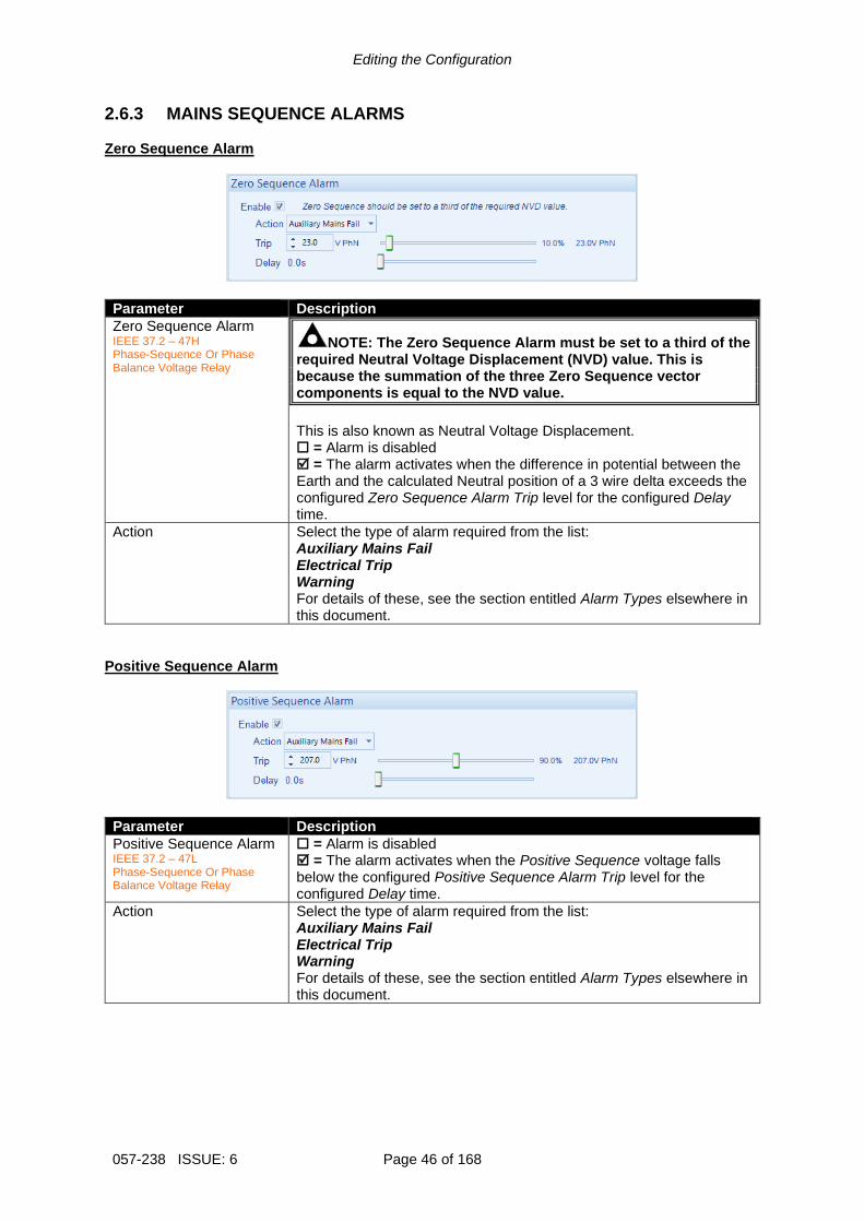
Editing the Configuration
057-238 ISSUE: 6 Page 46 of 168
2.6.3 MAINS SEQUENCE ALARMS Zero Sequence Alarm
Parameter Description
Zero Sequence Alarm IEEE 37.2 – 47H Phase-Sequence Or Phase Balance Voltage Relay
NOTE: The Zero Sequence Alarm must be set to a third of the required Neutral Voltage Displacement (NVD) value. This is because the summation of the three Zero Sequence vector components is equal to the NVD value.
This is also known as Neutral Voltage Displacement. = Alarm is disabled = The alarm activates when the difference in potential between the Earth and the calculated Neutral position of a 3 wire delta exceeds the configured Zero Sequence Alarm Trip level for the configured Delay time.
Action Select the type of alarm required from the list: Auxiliary Mains Fail Electrical Trip Warning For details of these, see the section entitled Alarm Types elsewhere in this document.
Positive Sequence Alarm
Parameter Description
Positive Sequence Alarm IEEE 37.2 – 47L Phase-Sequence Or Phase Balance Voltage Relay
= Alarm is disabled = The alarm activates when the Positive Sequence voltage falls below the configured Positive Sequence Alarm Trip level for the configured Delay time.
Action Select the type of alarm required from the list: Auxiliary Mains Fail Electrical Trip Warning For details of these, see the section entitled Alarm Types elsewhere in this document.
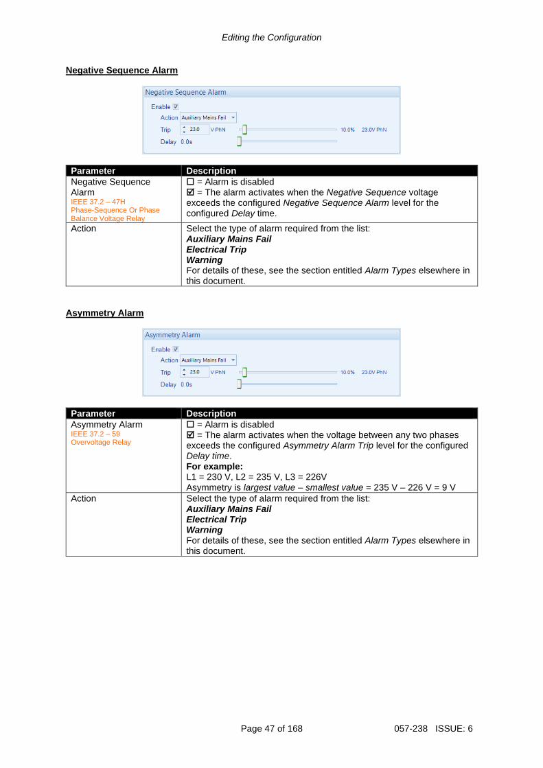
Editing the Configuration
Page 47 of 168 057-238 ISSUE: 6
Negative Sequence Alarm
Parameter Description
Negative Sequence Alarm IEEE 37.2 – 47H Phase-Sequence Or Phase Balance Voltage Relay
= Alarm is disabled = The alarm activates when the Negative Sequence voltage exceeds the configured Negative Sequence Alarm level for the configured Delay time.
Action Select the type of alarm required from the list: Auxiliary Mains Fail Electrical Trip Warning For details of these, see the section entitled Alarm Types elsewhere in this document.
Asymmetry Alarm
Parameter Description
Asymmetry Alarm IEEE 37.2 – 59 Overvoltage Relay
= Alarm is disabled = The alarm activates when the voltage between any two phases exceeds the configured Asymmetry Alarm Trip level for the configured Delay time. For example: L1 = 230 V, L2 = 235 V, L3 = 226V Asymmetry is largest value – smallest value = 235 V – 226 V = 9 V
Action Select the type of alarm required from the list: Auxiliary Mains Fail Electrical Trip Warning For details of these, see the section entitled Alarm Types elsewhere in this document.
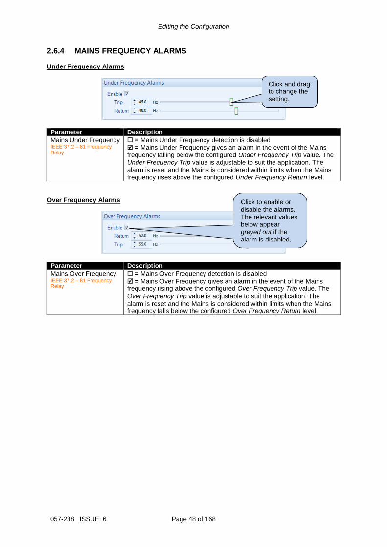
Editing the Configuration
057-238 ISSUE: 6 Page 48 of 168
2.6.4 MAINS FREQUENCY ALARMS Under Frequency Alarms
Parameter Description
Mains Under Frequency IEEE 37.2 – 81 Frequency Relay
= Mains Under Frequency detection is disabled = Mains Under Frequency gives an alarm in the event of the Mains frequency falling below the configured Under Frequency Trip value. The Under Frequency Trip value is adjustable to suit the application. The alarm is reset and the Mains is considered within limits when the Mains frequency rises above the configured Under Frequency Return level.
Over Frequency Alarms
Parameter Description
Mains Over Frequency IEEE 37.2 – 81 Frequency Relay
= Mains Over Frequency detection is disabled = Mains Over Frequency gives an alarm in the event of the Mains frequency rising above the configured Over Frequency Trip value. The Over Frequency Trip value is adjustable to suit the application. The alarm is reset and the Mains is considered within limits when the Mains frequency falls below the configured Over Frequency Return level.
Click to enable or disable the alarms. The relevant values below appear greyed out if the alarm is disabled.
Click and drag to change the setting.
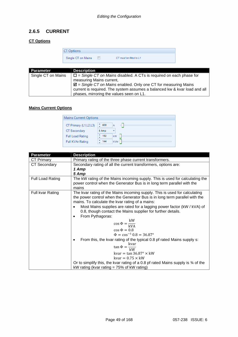
Editing the Configuration
Page 49 of 168 057-238 ISSUE: 6
2.6.5 CURRENT CT Options
Parameter Description
Single CT on Mains = Single CT on Mains disabled. A CTs is required on each phase for measuring Mains current, = Single CT on Mains enabled. Only one CT for measuring Mains current is required. The system assumes a balanced kw & kvar load and all phases, mirroring the values seen on L1.
Mains Current Options
Parameter Description
CT Primary Primary rating of the three phase current transformers.
CT Secondary Secondary rating of all the current transformers, options are: 1 Amp 5 Amp
Full Load Rating The kW rating of the Mains incoming supply. This is used for calculating the power control when the Generator Bus is in long term parallel with the mains
Full kvar Rating The kvar rating of the Mains incoming supply. This is used for calculating the power control when the Generator Bus is in long term parallel with the mains. To calculate the kvar rating of a mains:
• Most Mains supplies are rated for a lagging power factor (kW / kVA) of 0.8, though contact the Mains supplier for further details.
• From Pythagoras:
cosΦ =kW
kVA
cosΦ = 0.8
Φ = cos−1 0.8 = 36.87° • From this, the kvar rating of the typical 0.8 pf rated Mains supply s:
tanΦ =kvar
kW
kvar = tan 36.87° × kW
kvar = 0.75 × kW Or to simplify this, the kvar rating of a 0.8 pf rated Mains supply is ¾ of the kW rating (kvar rating = 75% of kW rating)
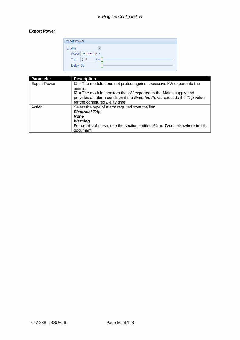
Editing the Configuration
057-238 ISSUE: 6 Page 50 of 168
Export Power
Parameter Description
Export Power = The module does not protect against excessive kW export into the mains. = The module monitors the kW exported to the Mains supply and provides an alarm condition if the Exported Power exceeds the Trip value for the configured Delay time.
Action Select the type of alarm required from the list: Electrical Trip None Warning For details of these, see the section entitled Alarm Types elsewhere in this document.
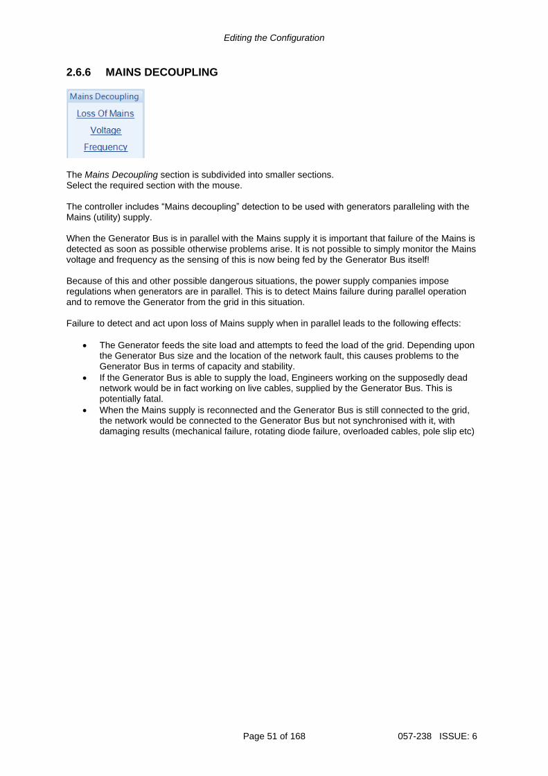
Editing the Configuration
Page 51 of 168 057-238 ISSUE: 6
2.6.6 MAINS DECOUPLING
The Mains Decoupling section is subdivided into smaller sections. Select the required section with the mouse. The controller includes “Mains decoupling” detection to be used with generators paralleling with the Mains (utility) supply. When the Generator Bus is in parallel with the Mains supply it is important that failure of the Mains is detected as soon as possible otherwise problems arise. It is not possible to simply monitor the Mains voltage and frequency as the sensing of this is now being fed by the Generator Bus itself! Because of this and other possible dangerous situations, the power supply companies impose regulations when generators are in parallel. This is to detect Mains failure during parallel operation and to remove the Generator from the grid in this situation. Failure to detect and act upon loss of Mains supply when in parallel leads to the following effects:
• The Generator feeds the site load and attempts to feed the load of the grid. Depending upon the Generator Bus size and the location of the network fault, this causes problems to the Generator Bus in terms of capacity and stability.
• If the Generator Bus is able to supply the load, Engineers working on the supposedly dead network would be in fact working on live cables, supplied by the Generator Bus. This is potentially fatal.
• When the Mains supply is reconnected and the Generator Bus is still connected to the grid, the network would be connected to the Generator Bus but not synchronised with it, with damaging results (mechanical failure, rotating diode failure, overloaded cables, pole slip etc)

Editing the Configuration
057-238 ISSUE: 6 Page 52 of 168
2.6.6.1 LOSS OF MAINS Options
Parameter Description
Action Select the required action when the module detects a Mains decoupling event: Auxiliary Mains Fail: Opens the Mains switchgear and allows the Generator Bus to continue providing power to the load. Electrical Trip: The Generator Bus switchgear is opened and the generators are allowed to perform a cooling run before being stopped. If the Mains is within limits after the decoupling event, it continues to supply the load. Warning: Audible alarm is generated but the switchgear is are not opened. For details of these, see the section entitled Alarm Types elsewhere in this document.
R.O.C.O.F. Alarm
Parameter Function
R.O.C.O.F. IEEE 37.2 - 81 Frequency relay
= R.O.C.O.F. protection is disabled = R.O.C.O.F. protection is enabled when the Generator Bus is in parallel with the Mains supply. R.O.C.O.F. detection senses sudden, fast changes in the frequency of the waveform. During the failure of the Mains supply when in parallel with the Generator bus, the frequency changes faster than is usual by either the on load Generator bus, or by the Mains supply.
Vector Shift Alarm
Parameter Function
Vector Shift = Vector Shift protection is disabled = Vector Shift protection is enabled. The Vector Shift Alarm activates when the generator/Mains voltage vector changes by more than the Trip setting. The Vector Shift Alarm is only enabled when the generator is in parallel with the Mains supply. Vector Shift detection measures the length of each cycle of the voltage wave. When the Mains fails in parallel with the Generator bus, the sudden change in load creates a change in the length of the cycle length.
Click to enable or disable the option. The relevant values below appear greyed out if the alarm is disabled.
Click and drag to change the setting.
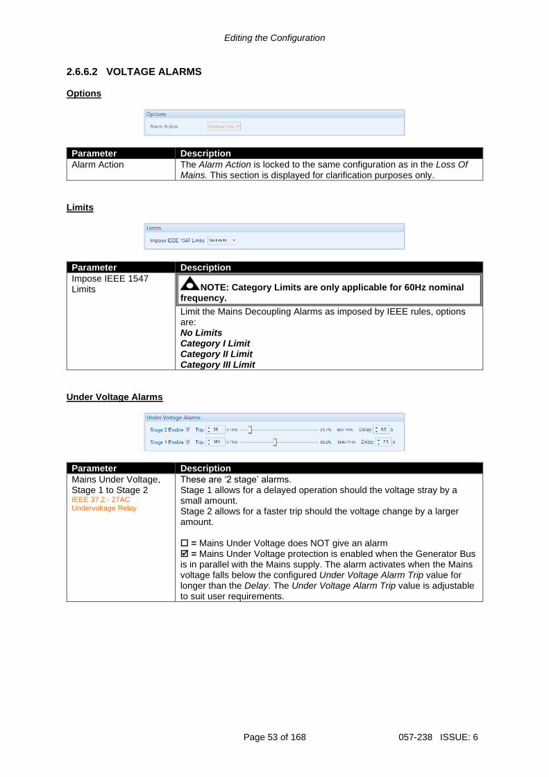
Editing the Configuration
Page 53 of 168 057-238 ISSUE: 6
2.6.6.2 VOLTAGE ALARMS Options
Parameter Description
Alarm Action The Alarm Action is locked to the same configuration as in the Loss Of Mains. This section is displayed for clarification purposes only.
Limits
Parameter Description
Impose IEEE 1547 Limits NOTE: Category Limits are only applicable for 60Hz nominal
frequency.
Limit the Mains Decoupling Alarms as imposed by IEEE rules, options are: No Limits Category I Limit Category II Limit Category III Limit
Under Voltage Alarms
Parameter Description
Mains Under Voltage, Stage 1 to Stage 2 IEEE 37.2 - 27AC Undervoltage Relay
These are ‘2 stage’ alarms. Stage 1 allows for a delayed operation should the voltage stray by a small amount. Stage 2 allows for a faster trip should the voltage change by a larger amount. = Mains Under Voltage does NOT give an alarm = Mains Under Voltage protection is enabled when the Generator Bus is in parallel with the Mains supply. The alarm activates when the Mains voltage falls below the configured Under Voltage Alarm Trip value for longer than the Delay. The Under Voltage Alarm Trip value is adjustable to suit user requirements.

Editing the Configuration
057-238 ISSUE: 6 Page 54 of 168
Nominal Voltage
Parameter Description
Mains Nominal Voltage The Mains Nominal Voltage is locked to the same configuration as the Bus Nominal Voltage. This section is displayed for clarification purposes only.
Over Voltage Alarms
Parameter Description
Mains Over Voltage, Stage 1 to Stage 2 IEEE 37.2 - 59AC Overvoltage Relay
These are ‘2 stage’ alarms. Stage 1 allows for a delayed operation should the voltage stray by a small amount. Stage 2 allows for a faster trip should the voltage change by a larger amount. = Mains Over Voltage does NOT give an alarm = Mains Over Voltage protection is enabled when the Generator Bus is in parallel with the Mains supply. The alarm activates when the Mains voltage rises above the configured Over Voltage Alarm Trip value for longer than the Delay. The Over Voltage Alarm Trip value is adjustable to suit user requirements.

Editing the Configuration
Page 55 of 168 057-238 ISSUE: 6
2.6.6.3 FREQUENCY Options
Parameter Description
Alarm Action The Alarm Action is locked to the same configuration as in the Loss Of Mains. This section is displayed for clarification purposes only.
Limits
Parameter Description
Impose IEEE 1547 Limits NOTE: Category Limits are only applicable for 60Hz nominal
frequency.
The Limits is locked to the same configuration as in the Mains Decoupling Voltage section’s Limits. This section is displayed for clarification purposes only.
Under Frequency Alarms
Parameter Description
Mains Under Frequency, Stage 1 to Stage 2 IEEE 37.2 – 81L Frequency Relay
These are ‘2 stage’ alarms. Stage 1 allows for a delayed operation should the frequency stray by a small amount. Stage 2 allows for a faster trip should the frequency change by a larger amount. = Mains Under Frequency does NOT give an alarm = Mains Under Frequency protection is enabled when the Generator Bus is in parallel with the Mains supply. The alarm activates when the Mains voltage falls below the configured Under Frequency Alarm Trip value for longer than the Delay. The Under Frequency Alarm Trip value is adjustable to suit user requirements.

Editing the Configuration
057-238 ISSUE: 6 Page 56 of 168
Nominal Frequency
Parameter Description
Mains Nominal Frequency
The Mains Nominal Frequency is locked to the same configuration as the Bus Nominal Frequency. This section is displayed for clarification purposes only.
Over Frequency Alarms
Parameter Description
Mains Over Frequency, Stage 1 to Stage 5 IEEE 37.2 – 81H Frequency Relay
These are ‘2 stage’ alarms. Stage 1 allows for a delayed operation should the frequency stray by a small amount. Stage 2 allows for a faster trip should the frequency change by a larger amount. = Mains Over Frequency does NOT give an alarm = Mains Over Frequency protection is enabled when the Generator Bus is in parallel with the Mains supply. The alarm activates when the Mains voltage rises above the configured Over Frequency Alarm Trip value for longer than the Delay. The Over Frequency Alarm Trip value is adjustable to suit user requirements.

Editing the Configuration
Page 57 of 168 057-238 ISSUE: 6
2.6.7 FAULT RIDE THROUGH
NOTE: To configure these settings refer to the appropriate grid standard for paralleling with the mains.
NOTE: The Fault Ride Through feature is used to prevent the Generator Bus being disconnected from the Mains when in parallel during a momentary Mains Failure. Care MUST be taken when configuring the Fault Ride Through feature as a prolonged time in parallel with a failed mains might cause a damage to the generators.
NOTE: For details on how the Fault Ride Through function operates refer to DSE Publication: 057-259 DSE8660 MKII Operator Manual which is found on our website: www.deepseaelectronics.com.
The Fault Ride Through feature is useful to prevent Electrical Trips on voltage dips caused by the grid when the generator bus is running in parallel with the Mains. This feature is also applicable when generators are load sharing in island mode. The feature is to ignore the following alarms:
• Under Voltage
• Over Voltage
• Under Frequency
• Over Frequency
• Mains Decoupling Voltage & Frequency Stage Alarms
• Voltage Symmetry
• Zero Sequence
• Negative Sequence
• Positive Sequence
• Phase Rotation The Fault Ride Through curve must be configured which is formed of a sequence of Connection Point Voltages which increase after consecutive time intervals. The Fault Ride Through curve allows to ignore the undervoltage alarms as long as the voltage dips are above the configured voltage levels defined by setpoints out of one, for the given times in seconds. The Fault Ride Through event activates when the voltage on one or more of the generator phases falls below the Urec3 level; and it is cleared when the Trec4 timer expires and the voltage rises above the Urec3 level. The Connection Point Voltages are configured in PU (Per Unit) which represent the percentages of the Mains Nominal Voltage; (i.e. 0.30PU = 30%). All the timers are configured in seconds.

Editing the Configuration
057-238 ISSUE: 6 Page 58 of 168
Parameter Description
Enable Fault Ride Through
= Fault Ride Through is disabled when the mains is in parallel with the generators bus = Fault Ride Through is enabled when the mains is in parallel with the generators bus
Enable In Island Mode
= Fault Ride Through is disabled when the generators are running on the bus but they are not in parallel with the mains. = Fault Ride Through is enabled when the generators are running on the bus but they are not in parallel with the mains.
Uret When the Fault Ride Through event starts, the voltage must remain above this level to ignore the Mains Low Voltage Alarm.
Tclear During the normal operation when the voltage drops below the Urec3 level this timer is started and the Fault Ride Through event is activated. After this time, the DSE module monitors the voltage to ensure it remains above the FRT curve to ignore the alarms. This timer ends at the next Connection Point Voltage (Uclear) of the curve.
Uclear The next Connection Point Voltage level at the Tclear time, above which the voltage must be to ignore the Mains Low Voltage Alarm.
Trec1 The time in seconds that the FRT event is active for. The voltage must be raised above the Urec1 level at this time.
Urec1 The next Connection Point Voltage level after the Trec1 time, above which the dipped voltage must be to ignore the Mains Low Voltage Alarm.
Trec2 The time in seconds that the FRT event is active for. After this time, the voltage must be raised above the Urec1 level to ignore the Mains Low Voltage Alarm.
Urec2 The next Connection Point Voltage level after the Trec3 time, above which the voltage must be to ignore the Mains Low Voltage Alarm.
Trec3 The time in seconds that the FRT event is active for. At this time, the voltage must be raised above the Urec2 level, but if the voltage is still below the Urec2, then the Fault Ride Through event terminates and the alarms are no longer ignored.
Parameters detailed overleaf…
Fault Occurs
Time since the fault occurred
Acceptable Voltage Region
Under Voltage Region
Connection Point Voltage as a percent of nominal

Editing the Configuration
Page 59 of 168 057-238 ISSUE: 6
Parameter Description
Urec3 The next Connection Point Voltage level after the Trec4 time, above which the voltage must be to terminate the Fault Ride Through event and activate the alarms.
Trec4 The time in seconds after which the DSE module monitors the voltage level to be raised above the Urec3 to clear the Fault Ride Through event. After this time, all the alarms are active until another Fault Ride Through event occurs. At this point, if the voltage is still below the Urec3 level, then the Fault Ride Through event remains active and the DSE module waits until the voltage is raised above the Urec3 to clear the Fault Ride Through event.
Save / Load Curve This feature is used to import the Fault Ride Through settings into another DSE module.
Parameter Description
Save Curve This allows saving the current configured settings of the Fault Ride Through into an FRT file.
Load Curve This allows loading of previously configured settings of the Fault Ride Through saved in FRT format.
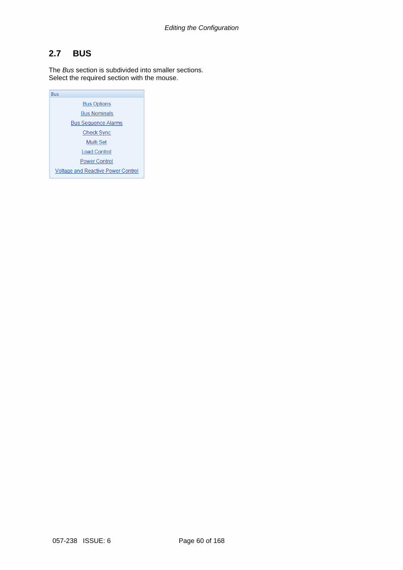
Editing the Configuration
057-238 ISSUE: 6 Page 60 of 168
2.7 BUS The Bus section is subdivided into smaller sections. Select the required section with the mouse.

Editing the Configuration
Page 61 of 168 057-238 ISSUE: 6
2.7.1 BUS OPTIONS AC System
Parameter Description
AC System The AC System of the Bus is fixed to the same setting as the mains. These settings are used to detail the type of AC system to which the module is connected: 2 Phase, 3 Wire L1 - L2 2 Phase, 3 Wire L1 - L3 3 Phase, 3 Wire 3 Phase, 3 Wire NVD 3 Phase, 4 Wire 3 Phase, 4 Wire Delta L1 - N - L2 3 Phase, 4 Wire Delta L1 - N - L3 3 Phase, 4 Wire Delta L2 - N - L3 Single Phase, 2 Wire Single Phase, 3 Wire L1 - L2 Single Phase, 3 Wire L1 - L3
VT Fitted = The voltage sensing to the controller is direct from the Generator bus = The voltage sensing to the controller is via Voltage Transformers (VTs or PTs) This is used to step down the generated voltage to be within the controller voltage specifications. By entering the Primary and Secondary voltages of the transformer, the controller displays the Primary voltage rather than the actual measured voltage. This is typically used to interface the DSE module to high voltage systems (i.e. 11kV)
This is ‘read only’ for information purposes.
The AC system is configured in the
Mains Options page.

Editing the Configuration
057-238 ISSUE: 6 Page 62 of 168
Breaker Control
Parameter Description
Bus Breaker Not Fitted NOTE: This feature is only supported when a single DSExx60 unit
is connected to the MSC link.
NOTE: When there is no Bus breaker for the module to control, this option MUST be enabled on all modules connected to the MSC link.
NOTE: When this feature is enabled, the Immediate Mains Dropout option is greyed out and forced to be enabled.
= Normal operation. When the module ramps the Generator Bus down to zero power, the Bus switchgear opens and the Generator Bus continues running in load share mode until requested to stop. = When the module ramps the Generator Bus down to zero power, the Mains switchgear remains closed and the Generator Bus continues to run in base load mode with both kW and kvar levels fixed at 0% until requested to stop. Activation of an Electrical Trip alarm on the module triggers an immediate alarm on the DSExx10 MKII which is Electrical Trip From 8660.
Enable Breaker Alarms
= Alarm is disabled = The Mains Breaker Alarms are enabled.
Fail To Open Delay When the Open Bus output is activated, if the configured Bus Closed Auxiliary digital input does not become inactive within the Bus Fail To Open Delay timer, the alarm is activated
Fail To Close Delay When the Close Bus output is activated, if the configured Bus Closed Auxiliary digital input does not become active within the Bus Fail To Close Delay timer, the alarm is activated
Phase Rotation
Parameter Description
Phase Rotation IEEE 37.2 – 47 Phase Sequence Relay
All the Bus Phase Rotation settings are locked to the same configuration as the Mains Phase Rotation settings. This section is displayed for clarification purposes only.

Editing the Configuration
Page 63 of 168 057-238 ISSUE: 6
2.7.2 BUS NOMINALS Nominal Voltage
Parameter Description
Nominal Voltage This is used to instruct the module what voltage to adjust the Generator Bus to whilst running on load. It is also used when the Bus and Mains VTs have different ratios, to synchronise the voltage of both supplies.
Nominal Frequency
Parameter Description
Nominal Frequency This is used to instruct the module what frequency to adjust the Generator Bus to whilst running on load.

Editing the Configuration
057-238 ISSUE: 6 Page 64 of 168
2.7.3 BUS SEQUENCE ALARMS Zero Sequence Alarm
Parameter Description
Zero Sequence Alarm IEEE 37.2 – 47H Phase-Sequence Or Phase Balance Voltage Relay
NOTE: The Zero Sequence Alarm must be set to a third of the required Neutral Voltage Displacement (NVD) value. This is because the summation of the three Zero Sequence vector components is equal to the NVD value.
This is also known as Neutral Voltage Displacement. = Alarm is disabled = The alarm activates when the difference in potential between the Earth and the calculated Neutral position of a 3 wire delta exceeds the configured Zero Sequence Alarm Trip level for the configured Delay time.
Action Select the type of alarm required from the list: Electrical Trip Warning For details of these, see the section entitled Alarm Types elsewhere in this document.
Positive Sequence Alarm
Parameter Description
Positive Sequence Alarm IEEE 37.2 – 47L Phase-Sequence Or Phase Balance Voltage Relay
= Alarm is disabled = The alarm activates when the Positive Sequence voltage falls below the configured Positive Sequence Alarm Trip level for the configured Delay time.
Action Select the type of alarm required from the list: Electrical Trip Warning For details of these, see the section entitled Alarm Types elsewhere in this document.

Editing the Configuration
Page 65 of 168 057-238 ISSUE: 6
Negative Sequence Alarm
Parameter Description
Negative Sequence Alarm IEEE 37.2 – 47H Phase-Sequence Or Phase Balance Voltage Relay
= Alarm is disabled = The alarm activates when the Negative Sequence voltage exceeds the configured Negative Sequence Alarm level for the configured Delay time.
Action Select the type of alarm required from the list: Electrical Trip Warning For details of these, see the section entitled Alarm Types elsewhere in this document.
Asymmetry Alarm
Parameter Description
Asymmetry Alarm IEEE 37.2 – 59 Overvoltage Relay
= Alarm is disabled = The alarm activates when the voltage between any two phases exceeds the configured Asymmetry Alarm Trip level for the configured Delay time. For example: L1 = 230 V, L2 = 235 V, L3 = 226V Asymmetry is largest value – smallest value = 235 V – 226 V = 9 V
Action Select the type of alarm required from the list: Electrical Trip Warning For details of these, see the section entitled Alarm Types elsewhere in this document.

Editing the Configuration
057-238 ISSUE: 6 Page 66 of 168
2.7.4 CHECK SYNC Dead Bus
Parameter Description
Voltage The Bus is measured when it is to be synchronised with the mains. If the Bus is measured to be below the Dead Bus Voltage, the Bus is assumed to be ‘dead’ and the synchronising does not begin. If the Bus is measured to be above the Dead Bus Voltage, the module synchronises the Bus to the Mains before both breakers are closed.
Check Sync
During the synchronising process, the module sends commands down the MSC to the DSExx10 modules to adjusts their generators frequency and voltage of the to closely match the mains. Typically the oncoming Bus is adjusted to be 0.1 Hz faster than the Mains supply, this causes the phase of the two supplies to change continuously. Before the breaker is closed, the following configurable conditions must be met.
Parameter Description
Low Frequency High Frequency
The difference between the two supplies frequencies must be between the Check Sync Low Frequency and Check Sync High Frequency
Voltage The difference between the two supplies voltages must be equal to or below the Check Sync Voltage
Phase Angle The phase of the two supplies must be equal to or below the Check Sync Phase Angle
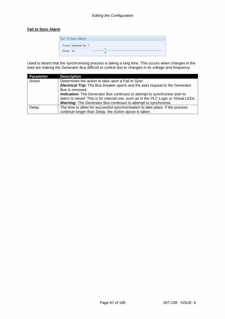
Editing the Configuration
Page 67 of 168 057-238 ISSUE: 6
Fail to Sync Alarm
Used to detect that the synchronising process is taking a long time. This occurs when changes in the load are making the Generator Bus difficult to control due to changes in its voltage and frequency.
Parameter Description
Action Determines the action to take upon a Fail to Sync. Electrical Trip: The Bus breaker opens and the start request to the Generator Bus is removed. Indication: The Generator Bus continues to attempt to synchronise and no alarm is raised. This is for internal use, such as in the PLC Logic or Virtual LEDs. Warning: The Generator Bus continues to attempt to synchronise.
Delay The time to allow for successful synchronisation to take place. If the process continue longer than Delay, the Action above is taken.

Editing the Configuration
057-238 ISSUE: 6 Page 68 of 168
2.7.5 MULTISET MSC Link
NOTE: The MSC Link Alarms are disabled by a digital input configured to MSC Alarms Inhibit if required.
NOTE: When the MSC2 (Redundant MSC Link) is enabled but the MSC1 is not wired, the DSE module issues an MSC Alarm preventing communication over the MSC2.
Parameter Description
MSC Failure Action
Action upon MSC Link Failure: Electrical Trip: The Bus breaker is opened immediately and the stopping sequence is initiated. Indication: The Generator Bus continues to run and no alarm is raised. This is used for internal use, such as in the PLC Logic or Virtual LEDs. Warning: The Generator Bus continues to run and a warning alarm is activated.
MSC Alarms Disabled Action
Action to take when the MSC alarm is disabled by a digital input: Indication: The Generator Bus continues to run and no alarm is raised. This is used for internal use, such as in the PLC Logic or Virtual LEDs. None: Alarm is disabled. Warning: The Generator Bus continues to run and a warning alarm is activated.
Too Few Modules Action
Action to take when the number of modules active on the MSC link is lower than the Minimum Modules on MSC link setting Electrical Trip: The Bus breaker is opened immediately and the stopping sequence is initiated. Indication: The Generator Bus continues to run and no alarm is raised. This is used for internal use, such as in the PLC Logic or Virtual LEDs. None: Alarm is disabled. Warning: The Generator Bus continues to run and a warning alarm is activated.
Minimum Modules On MSC Link
Set the minimum number of modules on the MSC before the Too Few Modules alarm is activated.
Parameters continued overleaf…

Editing the Configuration
Page 69 of 168 057-238 ISSUE: 6
Parameter Description
MSC Compatibility NOTE: MSC compatibility on this module is not supported with
DSE5560 and DSE7560 modules.
= The module is not able to communicate with DSE5510 and DSE7510 modules on the MSC Link = Communication with DSE5510 and DSE7510 series modules is possible. The maximum number of DSExx10 controllers is reduced to 16 and the maximum number of DSExx60 controllers is reduced to 8.
Enable Redundant MSC Link
NOTE: When required, this option must be enabled on all DSE8xxx MKII modules connected on the MSC Link.
NOTE: When the Redundant MSC Link is enabled, the PLC MSC Data is no longer available.
= Only one Multi-Set Comms (MSC) Link is active. = This activates the second (redundant) Multi-Set Comms (MSC) Link, allowing for communications redundancy between the controllers.
Disable Auto ID Allocation NOTE: When required, this option must be enabled on all
DSE8xxx MKII modules connected on the MSC Link.
= The MSC system assigns the MSC ID automatically when the DSE module is powered over the MSC network. = The MSC system does not assign the MSC ID automatically when the DSE module is powered up, instead the DSE module uses the MSC ID number configured in this section.
MSC Custom Data Enable NOTE: It is not possible to Write a configuration file to the module if
the Redundant MSC Link is enabled and PLC MSC Data is being transmitted over the MSC.
NOTE: For details on how to configure the PLC MSC Data, refer to DSE Publication: 057-314 Advanced PLC Software Manual which is found on our website: www.deepseaelectronics.com
= The MSC Custom Data is disabled and there are no PLC MSC items transmitted over the MSC Link = The MSC Custom Data is enabled, and the PLC MSC Data is transmitted on the MSC Link.
MSC Custom Data Transmission Rate
This option is available when the MSC Custom Data is enabled. Select the rate at which the PLC MSC Data is transmitted over the MSC Link.
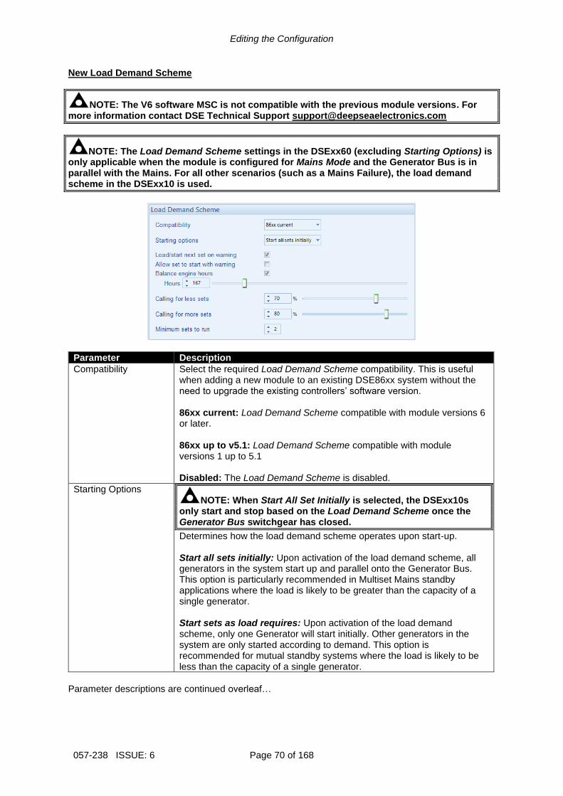
Editing the Configuration
057-238 ISSUE: 6 Page 70 of 168
New Load Demand Scheme
NOTE: The V6 software MSC is not compatible with the previous module versions. For more information contact DSE Technical Support [email protected]
NOTE: The Load Demand Scheme settings in the DSExx60 (excluding Starting Options) is only applicable when the module is configured for Mains Mode and the Generator Bus is in parallel with the Mains. For all other scenarios (such as a Mains Failure), the load demand scheme in the DSExx10 is used.
Parameter Description
Compatibility Select the required Load Demand Scheme compatibility. This is useful when adding a new module to an existing DSE86xx system without the need to upgrade the existing controllers’ software version. 86xx current: Load Demand Scheme compatible with module versions 6 or later. 86xx up to v5.1: Load Demand Scheme compatible with module versions 1 up to 5.1 Disabled: The Load Demand Scheme is disabled.
Starting Options NOTE: When Start All Set Initially is selected, the DSExx10s
only start and stop based on the Load Demand Scheme once the Generator Bus switchgear has closed.
Determines how the load demand scheme operates upon start-up. Start all sets initially: Upon activation of the load demand scheme, all generators in the system start up and parallel onto the Generator Bus. This option is particularly recommended in Multiset Mains standby applications where the load is likely to be greater than the capacity of a single generator. Start sets as load requires: Upon activation of the load demand scheme, only one Generator will start initially. Other generators in the system are only started according to demand. This option is recommended for mutual standby systems where the load is likely to be less than the capacity of a single generator.
Parameter descriptions are continued overleaf…

Editing the Configuration
Page 71 of 168 057-238 ISSUE: 6
Parameter Description
Load/Start Next Set on Warning NOTE: Enabling Start Next Set on Warning results with the All
Warnings are Latched option being forced on.
Whenever a warning occurs, a start/load command is issued over the MSC link to start the next highest priority generator. The Generator with the warning stops once the next highest priority Generator has joined the bus
Allow Set to Start with Warning
= If the MSC calls to start another generator, generators which display a warning status alarm remain at rest, only generators with no warning alarm are started according to their priority number. = Allows a stationary Generator with a warning alarm to start if requested.
Balance Engine Hours
Used in a Multiset system so that the engine’s priority changes according to the amount of usage of the generator. For instance, in a two Generator system. Generator 1 has logged 100 running hours Generator 2 has logged 20 running hours Balance engine hours are configured to 75 hours. Generator 2 has logged 80 hours less than Generator 1. As this is greater than the configured 75 hours, Generator 2 is the highest priority set. If all generators are within the configured Balance Engine Hours value, then the set Priority Number (See SCADA | Maintenance page) is followed.
Load Demand Delay
After closing into parallel, the Generator is kept running for the period of the Load Demand Delay time before joining the Load Demand Scheme.
Calling For Less Sets
The kW load level at which the module decides that Generator is disconnected from the Generator Bus. The Generator does not disconnect from the Bus when its percentage of kW is below the Calling For Less Sets value. Instead, the Generator disconnects from the Bus when it ensures that the remaining generators’ kW percentage is at the Calling For Less Sets value when it disconnects. This prevents the system from reaching a point where the load is such that the Generator starts and stops repeatedly. Once the load is below this level, the lowest priority Generator in the sequence (determined using the Genset Priority) begins its Return Delay timer. Once this has expired, the Generator ramps off and stops. If the load level rises above this set point during the Return Delay timer, the timer is cancelled and the Generator continues to supply power to the load. This caters for short term reductions in kW load demand.
Parameter descriptions are continued overleaf…

Editing the Configuration
057-238 ISSUE: 6 Page 72 of 168
Parameter Description
Calling For More Sets
The kW load level at which the module calls for additional generators to join the Generator Bus. Once the load is above this level, the highest priority Generator that is not running in the sequence (determined using the Genset Priority) begins its Start Delay timer. Once this has expired, the Generator joins the Bus and ramps up. If the load level reduces below this set point during the Start Delay timer, the timer is cancelled and the Generator enters its stops cycle. This caters for short term kW load demand. If the Generator fails to become available, it communicates this using the MSC Link which signals the next Generator in the sequence to take its place.
Minimum Sets to Run
The minimum number of generators that have to remain on the bus regardless of the load level and the Calling For Less Sets value. The MSC system selects the highest priority number Gensets to remain on the bus.

Editing the Configuration
Page 73 of 168 057-238 ISSUE: 6
2.7.6 LOAD CONTROL
NOTE: The Maximum Load Level are configured within the SCADA section. For further details, refer to section entitled Load Levels contained within the SCADA section elsewhere within this document.
NOTE: The ramping procedure changes depending upon the Alternative Ramping Scheme setting. For further details, refer section entitled Advanced elsewhere within this document.
The module performs a ‘soft’ load transfer when taking or removing load from the Generator Bus. Upon the generator bus’s switchgear closing, the module controls the Generator Bus’s power production starting from the zero. Load is then applied to the Generator Bus at the configured Ramp Up Rate. The ramping continues until Generator Bus is producing the power to the load, or to the Maximum Load Level when running in Bus Mode. Before the Generator Bus is disconnected, the load is ramped down to the zero at the configured Ramp Down Rate. The Generator Bus’s switchgear is opened once zero power has been attained, removing the Generator Bus from the load.
‘Soft’ load transfers of this type have many benefits, the most obvious are:
• When the Generator Bus is removed, the generators in the system are not suddenly unloaded with the load that was being supplied. Instead, the load is slowly ramped, allowing time for the Mains to take up the load.
• Opening of the switchgear occurs at a low load level, helping to reduce arcing of the contacts.
Switchgear Closed Switchgear Open
Ramp Down Rate
Ramp Up Rate
Ramped onto Load
Off Load
Power

Editing the Configuration
057-238 ISSUE: 6 Page 74 of 168
Load Share Ramp
Parameter Description
Ramp Up Rate The rate at which the Generator Bus is ramped onto the load.
Ramp Down Rate The rate at which the Generator Bus is ramped off the load
Ramp Off Load This is to set a time limit to the ramp down process, and it is useful when the engines responses are slow or are not capable to ramp off the load. The Ramp Off Load timer starts when the Generator Bus begins to ramp down. When this timer is expired the Bus breaker opens regardless of the actual power on the Bus. It is possible to set the ramp rate slower then this time, so the bus breaker opens prior to the ramp finishes.
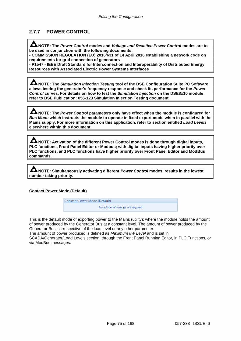
Editing the Configuration
Page 75 of 168 057-238 ISSUE: 6
2.7.7 POWER CONTROL
NOTE: The Power Control modes and Voltage and Reactive Power Control modes are to be used in conjunction with the following documents: - COMMISSION REGULATION (EU) 2016/631 of 14 April 2016 establishing a network code on requirements for grid connection of generators - P1547 - IEEE Draft Standard for Interconnection and Interoperability of Distributed Energy Resources with Associated Electric Power Systems Interfaces
NOTE: The Simulation Injection Testing tool of the DSE Configuration Suite PC Software allows testing the generator’s frequency response and check its performance for the Power Control curves. For details on how to test the Simulation Injection on the DSE8x10 module refer to DSE Publication: 056-123 Simulation Injection Testing document.
NOTE: The Power Control parameters only have effect when the module is configured for Bus Mode which instructs the module to operate in fixed export mode when in parallel with the Mains supply. For more information on this application, refer to section entitled Load Levels elsewhere within this document.
NOTE: Activation of the different Power Control modes is done through digital inputs, PLC functions, Front Panel Editor or Modbus; with digital inputs having higher priority over PLC functions, and PLC functions have higher priority over Front Panel Editor and ModBus commands.
NOTE: Simultaneously activating different Power Control modes, results in the lowest number taking priority.
Contact Power Mode (Default)
This is the default mode of exporting power to the Mains (utility); where the module holds the amount of power produced by the Generator Bus at a constant level. The amount of power produced by the Generator Bus is irrespective of the load level or any other parameter. The amount of power produced is defined as Maximum kW Level and is set in SCADA/Generator/Load Levels section, through the Front Panel Running Editor, in PLC Functions, or via ModBus messages.
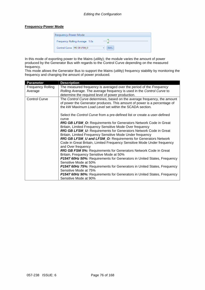
Editing the Configuration
057-238 ISSUE: 6 Page 76 of 168
Frequency-Power Mode
In this mode of exporting power to the Mains (utility); the module varies the amount of power produced by the Generator Bus with regards to the Control Curve depending on the measured frequency. This mode allows the Generator Bus to support the Mains (utility) frequency stability by monitoring the frequency and changing the amount of power produced.
Parameter Description
Frequency Rolling Average
The measured frequency is averaged over the period of the Frequency Rolling Average. The average frequency is used in the Control Curve to determine the required level of power production.
Control Curve The Control Curve determines, based on the average frequency, the amount of power the Generator produces. This amount of power is a percentage of the kW Maximum Load Level set within the SCADA section. Select the Control Curve from a pre-defined list or create a user-defined curve RfG GB LFSM_O: Requirements for Generators Network Code in Great Britain, Limited Frequency Sensitive Mode Over frequency RfG GB LFSM_U: Requirements for Generators Network Code in Great Britain, Limited Frequency Sensitive Mode Under frequency RfG GB LFSM_U and LFSM_O: Requirements for Generators Network Code in Great Britain, Limited Frequency Sensitive Mode Under frequency and Over frequency RfG GB FSM 5%: Requirements for Generators Network Code in Great Britain, Frequency Sensitive Mode at 50% P1547 60Hz 50%: Requirements for Generators in United States, Frequency Sensitive Mode at 50% P1547 60Hz 75%: Requirements for Generators in United States, Frequency Sensitive Mode at 75% P1547 60Hz 90%: Requirements for Generators in United States, Frequency Sensitive Mode at 90%

Editing the Configuration
Page 77 of 168 057-238 ISSUE: 6
Voltage-Power Mode
In this mode of exporting power to the Mains (utility); the module varies the amount of power produced by the Generator Bus with regards to the Control Curve depending on the measured voltage. This mode allows the Generator Bus to support the Mains (utility) voltage stability by monitoring the voltage and changing the amount of power produced.
Parameter Description
Voltage Rolling Average
The measured voltage is averaged over the period of the Voltage Rolling Average. The average voltage is used in the Control Curve to determine the required level of power production.
Control Curve The Control Curve determines, based on the average voltage, the amount of power the Generator Bus produces. This amount of power is a percentage of the kW Maximum Load Level. Select the Control Curve from a pre-defined list or create a user-defined curve Power Against Voltage
Power Ramp on Setpoint Change
Parameter Description
Ramp Rate When changing between Power Control modes or changing the set point, the Ramp Rate defines how fast the output power changes in percentage points per second.

Editing the Configuration
057-238 ISSUE: 6 Page 78 of 168
2.7.7.1 CREATING / EDITING THE POWER MODE CURVE While the DSE Configuration Suite holds most commonly used droop curves, occasionally it is required that the module’s droop function be configured for a specification application not listed by the DSE Configuration Suite. To aid this process, a droop curve editor is provided.
Click and drag the points on the graphs to change the settings
Use the mouse to select the graph point, then enter the value in the box or click up/down to change the value
Click OK to accept the changes or CANCEL to ignore and lose the changes.
Click SAVE AS, a prompt to name the curve…
Click OK to save the curve. Any saved curves become selectable in the Input Type selection list.
Hint: Deleting, renaming or editing custom sensor curves that have been added is performed in the main menu, select Tools | Curve Manager.
Click Interpolate then select two points as prompted to draw a straight line between them.
Click to change the range of the X and Y Axes of the graph and the level of open circuit detection
Double click the left mouse button to add a point or right click on a point to remove it.
Click to edit the curve or create a curve if a curve is not selected.
The curve that is to be used or edited.
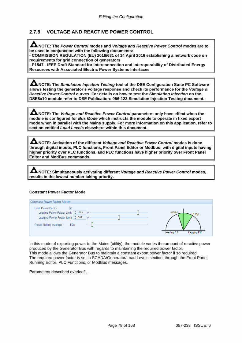
Editing the Configuration
Page 79 of 168 057-238 ISSUE: 6
2.7.8 VOLTAGE AND REACTIVE POWER CONTROL
NOTE: The Power Control modes and Voltage and Reactive Power Control modes are to be used in conjunction with the following documents: - COMMISSION REGULATION (EU) 2016/631 of 14 April 2016 establishing a network code on requirements for grid connection of generators - P1547 - IEEE Draft Standard for Interconnection and Interoperability of Distributed Energy Resources with Associated Electric Power Systems Interfaces
NOTE: The Simulation Injection Testing tool of the DSE Configuration Suite PC Software allows testing the generator’s voltage response and check its performance for the Voltage & Reactive Power Control curves. For details on how to test the Simulation Injection on the DSE8x10 module refer to DSE Publication: 056-123 Simulation Injection Testing document.
NOTE: The Voltage and Reactive Power Control parameters only have effect when the module is configured for Bus Mode which instructs the module to operate in fixed export mode when in parallel with the Mains supply. For more information on this application, refer to section entitled Load Levels elsewhere within this document.
NOTE: Activation of the different Voltage and Reactive Power Control modes is done through digital inputs, PLC functions, Front Panel Editor or Modbus; with digital inputs having higher priority over PLC functions, and PLC functions have higher priority over Front Panel Editor and ModBus commands.
NOTE: Simultaneously activating different Voltage and Reactive Power Control modes, results in the lowest number taking priority.
Constant Power Factor Mode
In this mode of exporting power to the Mains (utility); the module varies the amount of reactive power produced by the Generator Bus with regards to maintaining the required power factor. This mode allows the Generator Bus to maintain a constant export power factor if so required. The required power factor is set in SCADA/Generator/Load Levels section, through the Front Panel Running Editor, PLC Functions, or ModBus messages. Parameters described overleaf…

Editing the Configuration
057-238 ISSUE: 6 Page 80 of 168
Parameter Description
Limit Power Factor = The Generator Bus produces power beyond the power factor limits. Regardless of this setting, the generators do not produce more than their rated kvar. = The Generator Bus produces power within its specified power factor limits
Leading Power Factor Limit
The limit for Generator bus’s leading power factor.
Lagging Power Factor Limit
The limit for Generator bus’s lagging power factor.
Power Rolling Average
The exported power is averaged over the period of the Power Rolling Average. The average power is then used to determine the required reactive power production to achieve the set power factor.
Voltage-Reactive Power Mode
In this mode of exporting power to the Mains (utility); the module varies the amount of reactive power produced by the Generator Bus with regards to the Control Curve depending on the measured voltage. This mode allows the Generator Bus to support the Mains (utility) voltage stability by monitoring the voltage and changing the amount of reactive power produced.
Parameter Description
Limit Power Factor
= The Generator Bus produces power beyond the power factor limits. Regardless of this setting, the generators do not produce more than their rated kvar. = The Generator Bus produces power within its specified power factor limits.
Leading Power Factor Limit
The limit for Generator bus’s leading power factor.
Lagging Power Factor Limit
The limit for Generator bus’s lagging power factor.
Power Rolling Average
The exported power is averaged over the period of the Power Rolling Average. The average power is used to calculate the power factor if the option Limit Power Factor is enabled.
Voltage Rolling Average
The measured voltage is averaged over the period of the Voltage Rolling Average. The average voltage is used in the Control Curve to determine the required level of reactive power production.
Control Curve The Control Curve determines, based on the average voltage, the amount of reactive power the Generator Bus produces. This amount of power is a percentage of the kvar Maximum Load Level. Select the Control Curve from a pre-defined list or create a user-defined curve Reactive Power Against Voltage

Editing the Configuration
Page 81 of 168 057-238 ISSUE: 6
Power-Power Factor Mode
In this mode of exporting power to the Mains (utility); the module varies the amount of reactive power produced by the Generator Bus with regards to maintaining the required power factor. This power factor is derived from the averaged power using the Control Curve. This mode allows the Generator Bus to support the Mains (utility) stability by varying the power factor depending on the export power.
Parameter Description
Power Rolling Average
The exported power is averaged over the period of the Power Rolling Average. The average is then used in the Control Curve to determine the required power factor.
Control Curve The Control Curve determines, based on the average power, the power factor that is required. Select the Control Curve from a pre-defined list or create a user-defined curve Power Factor Against Power
Constant Reactive Power Mode (Default)
This is the default mode of exporting power to the Mains (utility); where the module holds the amount of reactive power produced by the Generator Bus at a constant level. The amount of reactive power produced by the Generator Bus is irrespective of the load level or any other parameter. The amount of reactive power produced is defined as Maximum kvar Level and is set in SCADA/Generator/Load Levels section, through the Front Panel Running Editor, in PLC Functions, or via ModBus messages.
Parameter Description
Limit Power Factor to Generator Rating
= The Generator Bus produces power beyond the power factor limits. Regardless of this setting, the generators do not produce more than their rated kvar. = The Generator Bus produces power within its specified power factor limits.
Reactive Power Ramp on Setpoint Change
Parameter Description
Ramp Rate When changing between Voltage and Reactive Power Control modes or changing the set point, the Ramp Rate defines how fast the output reactive power changes in percentage points per second.
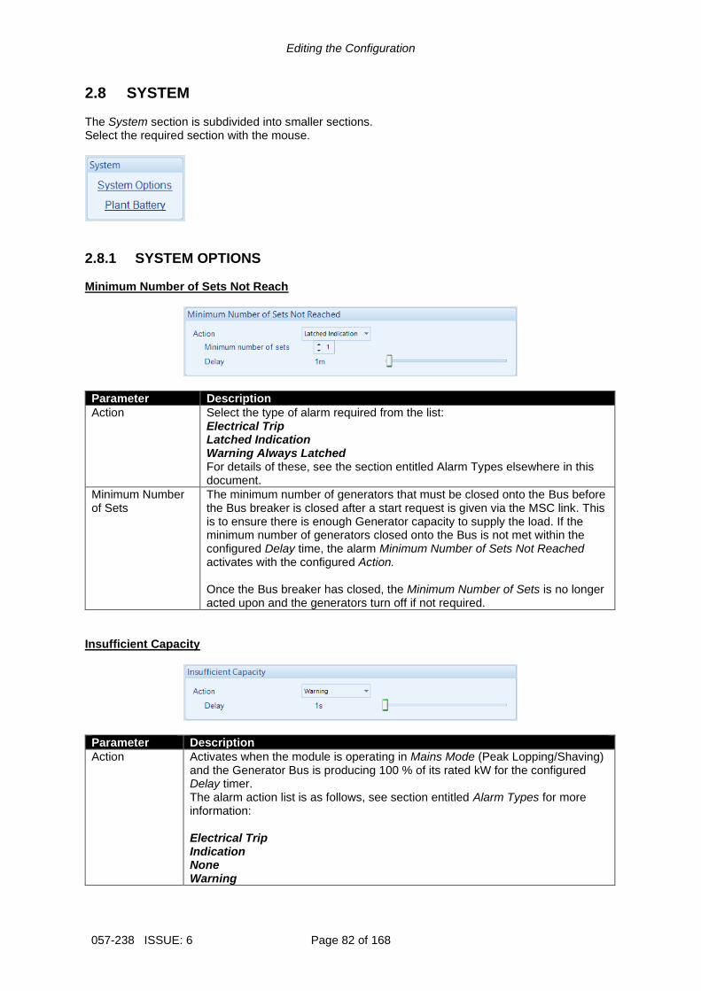
Editing the Configuration
057-238 ISSUE: 6 Page 82 of 168
2.8 SYSTEM The System section is subdivided into smaller sections. Select the required section with the mouse.
2.8.1 SYSTEM OPTIONS Minimum Number of Sets Not Reach
Parameter Description
Action Select the type of alarm required from the list: Electrical Trip Latched Indication Warning Always Latched For details of these, see the section entitled Alarm Types elsewhere in this document.
Minimum Number of Sets
The minimum number of generators that must be closed onto the Bus before the Bus breaker is closed after a start request is given via the MSC link. This is to ensure there is enough Generator capacity to supply the load. If the minimum number of generators closed onto the Bus is not met within the configured Delay time, the alarm Minimum Number of Sets Not Reached activates with the configured Action. Once the Bus breaker has closed, the Minimum Number of Sets is no longer acted upon and the generators turn off if not required.
Insufficient Capacity
Parameter Description
Action Activates when the module is operating in Mains Mode (Peak Lopping/Shaving) and the Generator Bus is producing 100 % of its rated kW for the configured Delay timer. The alarm action list is as follows, see section entitled Alarm Types for more information: Electrical Trip Indication None Warning

Editing the Configuration
Page 83 of 168 057-238 ISSUE: 6
Load CT
NOTE: For more information on the Load CT, refer to DSE Publication: 056-007 Advantages of Load CT which is found on our website: www.deepseaelectronics.com
The load CT is only required when there is more than one DSExx60 module connected on the MSC link. With the load CT fitted, the module transfers the right amount of load back to the Mains before disconnecting the Generator Bus. This prevents the Generator Bus being ‘shock loaded’. Without the load C.T., the module does not know how much load to transfer to the Mains when other DSExx60 modules are also running in island mode. This results in the module transferring a pre-determined amount of load before disconnecting the Generator Bus from the mains. This amount is configured by the Min Mains Power to Open Bus setting. Hence, there is either too much load, or not enough load transferred, and the Generator Bus is ‘shock loaded’ as it is disconnected from the mains.
Parameter Description
Load CT Enable = The Load CT is disabled and the Min Mains Power to Open Bus is enabled. = The Load CT enabled and the Min Mains Power to Open Bus is disable. There is only one CT for measuring/calculating load current and it must be fitted on L1. The system assumes a balanced kw & kvar load on all phases, mirroring the values seen on L1.
CT Primary Primary rating of the Current Transformer
CT Secondary Secondary rating of the Current Transformer
CT Voltage The supply voltage used to multiply with the load current to calculate the load kW and kvar. This is useful when the system has different voltages for the Bus and Mains sensing. Bus: The Load CT is at the same potential as the Bus sensing. Mains: The Load CT is at the same potential as the Mains sensing.
CT Location NOTE: For more information on the Load CT location, refer to DSE
Publication: 057-259 DSE8660 MKII Operator Manual which is found on our website: www.deepseaelectronics.com
The location where the L1 ‘Load CT’ is situated: Bus: The ‘Load CT’ is situated on the L1 feed from the Generator Bus. The load current and power is calculated. Load: The ‘Load CT’ is situated on the common L1 feed to the load. The load current and power is measured.
Min Mains Power to Open Bus NOTE: This parameter is only available when the Load CT is not
enabled.
The amount of Mains power at which the Generator Bus breaker opens when the Generator Bus is ramping down.

Editing the Configuration
057-238 ISSUE: 6 Page 84 of 168
2.8.2 PLANT BATTERY Voltage Alarms
Parameter Description
Plant Battery Under Voltage IEEE 37.2 -27 DC Undervoltage Relay
= The alarm is disabled. = The alarm activates when the battery voltage drops below the configured Pre-Alarm level for the configured Delay time. When the battery voltage rises above the configured Return level, the alarm is de-activated.
Plant Battery Over Voltage IEEE 37.2 -59 DC Overvoltage Relay
= The alarm is disabled. = The alarm activates when the battery voltage rises above the configured Pre-Alarm level for the configured Delay time. When the battery voltage drops below the configured Return level, the alarm is de-activated.

Editing the Configuration
Page 85 of 168 057-238 ISSUE: 6
2.9 COMMUNICATIONS The Communications page is subdivided into smaller sections. Select the required section with the mouse.
2.9.1 COMMUNICATIONS OPTIONS Provides a means of giving the controller an identity. This is used in the SCADA section to allow the operator to see the site name and site identity that it is currently connected to.
Parameter Description
Site Identity A free entry boxes to allow the user to give the DSE module a description of where the site is located. This text is not shown on the module’s display and is only seen when performing remote communication. This aids the user in knowing where the site is located.
Genset Identity A free entry boxes to allow the user to give the DSE module a description of which transfer switch it is connected to. This text is not shown on the module’s display and is only seen when performing remote communication. This aids the user in knowing which transfer switch on a specific site is being monitored.
Free text entries to identify the system. This text is displayed on the SCADA screen when the module is connected to the PC.

Editing the Configuration
057-238 ISSUE: 6 Page 86 of 168
2.9.2 RS232 PORT The RS232 Port page is subdivided into smaller sections. Select the required section with the mouse.

Editing the Configuration
Page 87 of 168 057-238 ISSUE: 6
2.9.2.1 BASIC Serial Port Configuration
NOTE: Connecting a modem directly to the module’s RS232 for is legacy support only. When a new installation requires remote communication using the cellular network is required, refer to DSE products DSE890, DSE891 and DSEWebNet on the DSE website: www.deepseaelectronics.com.
NOTE: When the RS232 Port Usage is configured to “PLC Comms”, the transmitting module’s Port Usage must be configured to “Gencomm”. This allows the module configured as “PLC Comms” act as a master and read from the module configured to “Gencomm”. Every device on the RS232 link must have an individual Slave ID. For details on how to configure the PLC Editor to read via its RS232, refer to DSE Publication: 057-314 Advanced PLC Software Manual which is found on our website: www.deepseaelectronics.com
Parameter Description
Slave ID Select the Slave ID of the DSE module’s RS232 port.
Baud Rate Select the Baud Rate (speed of communication) of the DSE module’s RS232 port. Every device on the RS232 link must have the same Baud Rate. 1200 2400 4800 9600 14400 19200 28800 38400 57600 115200
Port Usage NOTE: In a system for a PLC Comms application, only one DSE module
must be configured to act as the PLC master. For further details and instructions on using the PLC Comms, refer to DSE Publication: 057-314 Advanced PLC Software Manual which is found on our website: www.deepseaelectronics.com
No Modem: RS232 ports is used for direct RS232 connection to PLC, BMS etc Incoming Modem Calls: RS232 port connected to modem, used to accept incoming calls from a PC only. Incoming And Outgoing Modem (Sequence): RS232 port connected to modem used to accept incoming calls from a PC and also make calls upon events. When multiple Alarm Numbers are configured, the module attempts to dial each number. When the dial out call fails to one of the configured numbers, the module attempts to call that number for the configured number of Retries, before it carries on to the next number.
Parameter descriptions are continued overleaf…

Editing the Configuration
057-238 ISSUE: 6 Page 88 of 168
Parameter Description
Port Usage Incoming And Outgoing Modem (Cyclic): RS232 port connected to modem used to accept incoming calls from a PC and also make calls upon events. When multiple Alarm Numbers are configured, the module attempts to dial each number. When the dial out call fails to one of the configured numbers, the module completes the cycle and re-attempts to call those numbers for the configured number of Retries. Outgoing Modem Alarms (Sequence): RS232 port connected to modem, used to make calls upon events. When multiple Alarm Numbers are configured, the module attempts to dial each number. When the dial out call fails to one of the configured numbers, the module attempts to call that number for the configured number of Retries, before it carries on to the next number. Outgoing Modem Alarms (Cyclic): RS232 port connected to modem, used to make calls upon events. When multiple Alarm Numbers are configured, the module attempts to dial each number. When the dial out call fails to one of the configured numbers, the module completes the cycle and re-attempts to call those numbers for the configured number of Retries. PLC Comms: RS232 port is used to read the connected controller’s registers over the RS232 which are defined in the PLC Editor.

Editing the Configuration
Page 89 of 168 057-238 ISSUE: 6
Modem Settings
NOTE: Connecting a modem directly to the module’s RS232 is for legacy support only. When a new installation requires remote communication using the cellular network is required, refer to DSE products DSE890, DSE891 and DSEWebNet on the DSE website: www.deepseaelectronics.com.
Parameter Description
Alarm Number The phone number that the module dials upon an event. This number must be connected to a PC modem on a PC running the DSE Configuration Suite Software. Leave this field empty when dial-out to a PC is not required.
GSM Modem = The connected modem is a fixed line telephone modem = The connected modem is a GSM (cellular) modem. The GSM signal strength meter and GSM operator are shown on the module display.
SMS Message Centre Number
The Message centre used to send SMS messages. This number is obtained from the GSM operator.
SMS Recipient Numbers
Numbers of the cell phones to send SMS messages to. Leave blank if SMS function is not required.

Editing the Configuration
057-238 ISSUE: 6 Page 90 of 168
2.9.2.2 ADVANCED
NOTE: Connecting a modem directly to the module’s RS232 is for legacy support only. When a new installation requires remote communication using the cellular network is required, refer to DSE products DSE890, DSE891 and DSEWebNet on the DSE website: www.deepseaelectronics.com.
Initialisation Strings
The initialisation strings are commands that are sent to the modem upon powering up the DSE module and additionally at regular intervals subsequently, whenever the DSE module initialises (resets) the modem. Factory Set Initialisation Strings
Parameter Description
E0 Echo off
S7=60 Wait for carrier time 60s
S0=0 (not auto answer) S0=2 (auto answer)
Do not answer Answer after two rings
&S0 DSR always on
&C1 DCD is active if modem is online
&D3 Reset (ATZ) on DTR-drop
H0 Hang up (disconnect)
Silent Operation The modem connected to the DSE controller usually makes dialling noises and ‘squeal’ in the initial stages of making a data call. To control this noise, add the following command to the end of the initialisation string:
Parameter Description
M0 Silent operation
M1 Sounds during the initial stages of making a data call
M2 Sounds always when connected (not recommended for troubleshooting)

Editing the Configuration
Page 91 of 168 057-238 ISSUE: 6
Sierra/Wavecom Fastrak Supreme GSM Modem Initialisation Strings When connected to the Wavecom Fastrak Supreme GSM modem, the initialisation strings must be altered by changing the factory set &D3 to &D2.
Parameter Description
&D2 (required for Sierra / Wavecom Fastrak Supreme) Hang up on DTR-drop
&D3 (DSE module factory settings) Reset on DTR-drop
Other Modems When using modems not recommended by DSE, first try either of the options shown above. If problems are still encountered, contact your modem supplier for further advice. Connection Settings
Parameter Description
Master Inactivity Timeout
The module monitors by default the USB port for communications. When activity is detected on the RS232 port, the module monitors the port for further data. If no data activity is detected on the port for the duration of the Master Inactivity Timer, it reverts to looking at the USB port. This needs to be set longer than the time between ModBus polls from the master.
Connect Delay The amount of time that is allowed to elapse between the alarm being registered and the controller dialling out with the fault.
Retries The number of times the module attempts to contact the remote PC by modem.
Retry Delay The amount of time between retries
Repeat Cycle Delay The amount of time between the cycle repeats when dialling out calls to multiple Alarm Numbers fails.
Inter-frame Delay Set the time delay between the DSE module receiving a MODBUS RTU request and the DSE module’s response.

Editing the Configuration
057-238 ISSUE: 6 Page 92 of 168
2.9.2.3 SMS CONTROL
NOTE: Connecting a modem directly to the module’s RS232 for is legacy support only. When a new installation requires remote communication using the cellular network is required, refer to DSE products DSE890, DSE891 and DSEWebNet on the DSE website: www.deepseaelectronics.com.
Parameter Description
Require PIN = A control code sent by SMS does not require a PIN code entered before the code. = For security, the configured PIN Prefix must be entered in the SMS prior to the control code.
Start Off Load (Code 1)
= Sending code 1 to the module via SMS does not issue a Start Off Load command. = When in Auto mode, the module performs the start sequence but the Generator Bus is not instructed to take the load when code 1 is sent via SMS. This function is used where the Generator Bus only run is required e.g. for exercise.
Start In Parallel (Code 2)
= Sending code 2 to the module via SMS does not issue a Start On Load command. = When in auto mode, the module performs the start sequence and places the Generator Bus in long term parallel when code 2 is sent via SMS.
Cancel (Code 3)
= Sending code 3 to the module via SMS does not issue a cancel the start command issued by code 1 or 2. = Sending code 3 to the module via SMS cancels the start command issued by code 1 or 2.
Stop Mode (Code 4)
= Sending code 4 to the module via SMS does not issue place the unit into its Stop Mode. = Sending code 4 to the module via SMS mimics the operation of the ‘Stop’ button and is used to provide a remote SMS stop command.
Auto Mode (Code 5)
= Sending code 5 to the module via SMS does not issue place the unit into its Auto Mode. = Sending code 5 to the module via SMS mimics the operation of the Auto button.
Start in Island Mode (Code 6)
= Sending code 2 to the module via SMS does not issue a Start in Island command. = When in auto mode, the module performs the start sequence and transfers all the load to the Generator Bus and disconnects the mains, when code 2 is sent via SMS.

Editing the Configuration
Page 93 of 168 057-238 ISSUE: 6
2.9.2.4 TROUBLESHOOTING MODEM COMMUNICATIONS
NOTE: Connecting a modem directly to the module’s RS232 for is legacy support only. When a new installation requires remote communication using the cellular network is required, refer to DSE products DSE890, DSE891 and DSEWebNet on the DSE website: www.deepseaelectronics.com.
2.9.2.4.1 MODEM COMMUNICATION SPEED SETTING First ensure the modem is set to communication with the DSE module at 9600 baud – Modems supplied by DSE are factory adjusted to operate with the DSE module. Only modems purchased from a third party may require adjustment. To change the modems RS232 baud rate you need a command line terminal program (HyperTerminal by Microsoft is a good solution). Operation of this terminal program is not supported by DSE; contact your terminal program supplier. Connect the modem RS232 port to your PCs RS232 port. You may need an additional card in your PC to provide this facility. Use HyperTerminal (or similar) to connect to the modem at its current baud rate. You may need to contact your modem supplier to obtain this detail. If this is not possible, use ‘trial and error’ methods. Select a baud rate, attempt connection, press <ENTER> a few times. If the modem responds with OK>
then you are connected at the correct baud rate. Any other response (including nothing) means you are not connected so select another baud rate. When connected, enter the following command: AT+IPR=9600 and press <ENTER>
This sets the modem to 9600 baud. Close the HyperTerminal connection (do not remove power from the modem) then open a new connection to the modem at 9600 baud. Enter the following command: AT&W and press <ENTER>
This saves the new setting in the modem. Power is now removed. The next time power is applied, the modem starts with the new settings (Baud rate = 9600), suitable to communicate with the DSE module. 2.9.2.4.2 GSM MODEM CONNECTION Most GSM modems have a Status LED. The Wavecom Fastrack Supreme as recommended and previously supplied by DSE has a RED Status LED, operating as follows.
LED State Description
Off Modem is not powered
On Continuous Not connected to GSM network
Flashing Slow (approximately once every two seconds)
Connected to GSM network
Flashing Fast (approximately twice per second)
Connected to GSM network data transmission in progress.

Editing the Configuration
057-238 ISSUE: 6 Page 94 of 168
2.9.3 RS485 PORTS
NOTE: When the RS485 Port Usage is configured to “PLC Comms”, all other modules’ Port Usage must be configured to “Gencomm”. This allows the module configured as “PLC Comms” to act as a master and read from the module(s) configured to “Gencomm”. For details on how to configure the PLC Editor to read via its RS485, refer to DSE Publication: 057-314 Advanced PLC Software Manual which is found on our website: www.deepseaelectronics.com
Parameter Description
Slave ID Select the Slave ID of the DSE module’s RS485 port. Every device on the RS485 link must have an individual Slave ID.
Baud Rate Select the Baud Rate (speed of communication) of the DSE module’s RS485 port. Every device on the RS485 link must have the same Baud Rate. 1200 2400 4800 9600 14400 19200 28800 38400 57600 115200
Port Usage NOTE: In a system for a PLC Comms application, only one
DSE module must be configured to act as the PLC master. For further details and instructions on using the PLC Comms, refer to DSE Publication: 057-314 Advanced PLC Software Manual which is found on our website: www.deepseaelectronics.com
Select the RS485 Port1 usage. Gencomm: MODBUS RTU RS485 communication PLC Comms: The RS485 Port 1 is used to read the other controllers’ registers over the RS485 link which are defined in the PLC Editor.
Master Inactivity Timeout Set the time delay between a MODBUS RTU request and the receipt of a response. The module monitors by default the USB port for communications. When activity is detected on the RS485 port, the module monitors the port for further data. If no data activity is detected on the port for the duration of the Master Inactivity Timer, it reverts to looking at the USB port. This needs to be set longer than the time between MODBUS polls from the master.
Inter-frame Delay Set the time delay between the DSE module receiving a MODBUS RTU request and the DSE module’s response.

Editing the Configuration
Page 95 of 168 057-238 ISSUE: 6
2.9.4 ETHERNET
NOTE: Consult the network administrator of the host network before changing these settings. Incorrect settings cause network errors in the existing local area network. These settings must only be changed by qualified network administrators.
Dynamic Host Configuration Protocol
Parameter Description
Obtain IP Address Automatically
= The Dynamic Host Configuration Protocol (DHCP) is disable and the unit has a fixed IP address as configured in the IP Address section. = The Dynamic Host Configuration Protocol (DHCP) is enable and the unit automatically attains an IP address from the network it is connected to if it has DHCP enabled.
Names
Parameter Description
Domain Name The hostname of the device which is used for DHCP requests and acknowledgements. Consult the network IT manager for suitable naming
Host Name Additional description string for DHCP
Vendor Name Additional description string for DHCP

Editing the Configuration
057-238 ISSUE: 6 Page 96 of 168
IP Address
Parameter Description
IP Address The static IP address of the module.
Subnet Mask The subnet mask is to determine whether the module is on the local subnet or on a remote network.
Gateway Address IP address of the internet router that module is connected to.
DNS Address IP address of the Domain Name Service (DNS). Usually this is the same as the module’s IP address.
Preferred Connection Address
The module allows up to five MODBUS masters to connect to it. The Preferred Connection Address enables the unit to reserve one of the five connections for a specific IP address, such as for a remote display module to ensure it always connects.
MODBUS
Parameter Description
Modbus Port Number The port number which the module serves MODBUS traffic on.

Editing the Configuration
Page 97 of 168 057-238 ISSUE: 6
2.9.4.1 FIREWALL CONFIGURATION FOR INTERNET ACCESS As modem/routers differ enormously in their configuration, it is not possible for DSE to give a complete guide to their use with the DSE module. However it is possible to give a description of the requirements in generic terms. For details of how to achieve the connection to your modem/router you are referred to the supplier of your modem/router equipment. The DSE module makes its data available to a configurable TCP port number. You must configure your modem/router to allow inbound traffic on this port. For more information you are referred to your WAN interface device (modem/router) manufacturer.
2.9.4.2 INCOMING TRAFFIC (VIRTUAL SERVER) Network Address and Port Translation (NAPT) allows a single device, such as the modem/router gateway, to act as an agent between the Internet (or "public external network") and a local (or "internal private") network. This means that only a single, unique IP address is required to represent an entire group of computers. For our DSE module application, this means that the WAN IP address of the modem/router is the IP address we need to access the site from an external (internet) location. When requests reach the modem/router, we want this passed to a ‘virtual server’ for handling, in our case this is the DSE module. Example:
Virtual Servers
Filter Name Source Port Destination (LAN) Address
DSE8660 MKII 1003 192.168.1.45
Result : Traffic arriving from the WAN (internet) on port 1003 is automatically sent to IP address 192.168.1.45 on the LAN (DSE module) for handling.
IP Address of the DSE controller connected to the LAN.
Port number of the communications (must match the configuration of the DSE controller).
User provided name for the Port Forwarding rule.

Editing the Configuration
057-238 ISSUE: 6 Page 98 of 168
2.9.5 NOTIFICATIONS The Notifications page is subdivided into smaller sections. Select the required section with the mouse.
2.9.5.1 SNMP
NOTE: The SNMP V2c MIB file for the module is available to download from the DSE website: www.deepseaelectronics.com.
The module supports SNMP v2c with GetRequest, SetRequest, GetNextRequest, GetBulkRequest and Response. The module also allows communication up to two different SNMP managers at the same time on different IP addresses. A fixed MIB file is available for the module for use by external SNMP managers. The MIB file is a file used by the SNMP manager to give context to the information held within the module.
Parameter Description
Enable = The SNMP function is disabled = The SNMP function is enabled. The module communicates with the SNMP manager using its ethernet port.
Device Name The name of the module which is attainable by SNMP requests using sysName OID contained within the standard RFC1213 MIB file.
Manager 1 Address The static IP address of the first SNMP manager.
Manager 2 Address The static IP address of the second SNMP manager.
Manager Port The port number which the module serves SNMP GET, GET Next, Get Bulk, Get Subtree, Walk and SET messages.
Notification Port The port number which the module sends SNMP TRAP messages via.
Read Community String The SNMP Read Community String. (Factory setting public)
Write Community String The SNMP Write Community String. (Factory setting private)

Editing the Configuration
Page 99 of 168 057-238 ISSUE: 6
2.9.5.2 NOTIFICATIONS The user is able to select the types of events which are sent to the SNMP managers as SNMP TRAP messages.
Parameter Description
Named Alarms = No SNMP TRAPs are sent when a Named Alarm activates. = An SNMP TRAP is sent when a Named Alarm activates. A Named Alarm is a protection with a pre-set name, e.g. Fail to Synchronise.
Unnamed Alarms = No SNMP TRAPs are sent when an Unnamed Alarm activates. = An SNMP TRAP is sent when an Unnamed Alarm activates. An Unnamed Alarm is a protection with a user configured name, e.g. a digital input configured for User Configured.
Mode Change = No SNMP TRAPs are sent when the module changes operating mode. = An SNMP TRAP is sent to indicate the operating mode has changed and what is has changed to.
Power Up = No SNMP TRAPs are sent when the module powers up. = An SNMP TRAP is sent when the module powers up.
Mains Fail = No SNMP TRAPs are sent when module detects a Mains failure. = An SNMP TRAP is sent when the module detects a Mains failure.
Mains Return = No SNMP TRAPs are sent when the module detects the Mains has returned. = An SNMP TRAP is sent when the module detects the Mains has returned.
Bus Off Load = No SNMP TRAPs are sent when the Generator Bus switchgear opens . = An SNMP TRAP is sent when the Generator Bus switchgear opens.
Bus On Load = No SNMP TRAPs are sent when the Generator Bus switchgear closes. = An SNMP TRAP is sent when the Generator Bus switchgear closes.

Editing the Configuration
057-238 ISSUE: 6 Page 100 of 168
2.10 SCHEDULER The section is subdivided into smaller sections.
2.10.1 SCHEDULER OPTIONS
Function Description
Enable Exercise Scheduler
= The scheduler is disabled. = The scheduler is enabled, Bank 1 and Bank 2 become editable.
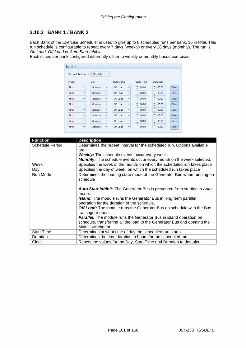
Editing the Configuration
Page 101 of 168 057-238 ISSUE: 6
2.10.2 BANK 1 / BANK 2 Each Bank of the Exercise Scheduler is used to give up to 8 scheduled runs per bank, 16 in total. This run schedule is configurable to repeat every 7 days (weekly) or every 28 days (monthly). The run is On Load, Off Load or Auto Start Inhibit. Each scheduler bank configured differently either to weekly or monthly based exercises.
Function Description
Schedule Period Determines the repeat interval for the scheduled run. Options available are: Weekly: The schedule events occur every week. Monthly: The schedule events occur every month on the week selected.
Week Specifies the week of the month, on which the scheduled run takes place
Day Specifies the day of week, on which the scheduled run takes place
Run Mode Determines the loading state mode of the Generator Bus when running on schedule Auto Start Inhibit: The Generator Bus is prevented from starting in Auto mode. Island: The module runs the Generator Bus in long term parallel operation for the duration of the schedule. Off Load: The module runs the Generator Bus on schedule with the Bus switchgear open. Parallel: The module runs the Generator Bus in island operation on schedule, transferring all the load to the Generator Bus and opening the Mains switchgear.
Start Time Determines at what time of day the scheduled run starts
Duration Determines the time duration in hours for the scheduled run
Clear Resets the values for the Day, Start Time and Duration to defaults

Editing the Configuration
057-238 ISSUE: 6 Page 102 of 168
2.11 EXPANSION The Expansion page is subdivided into smaller sections. Select the required section with the mouse.
See overleaf for description of the different expansion modules.

Editing the Configuration
Page 103 of 168 057-238 ISSUE: 6
2.11.1 DSE2130 INPUT MODULES Select the DSENet ID of the input expansion to be configured. The ID of the expansion module is set by rotary decimal switch accessible under the removable cover of the device.
The following options are then shown: 2130 Expansion Enable
Parameter Description
Expansion Enabled = The expansion module with the selected ID is not enabled. = The expansion module with the selected ID is enabled. If the expansion module is not connected / detected by the module, the module generates an Exp. Unit Failure alarm with the configured Link Lost Alarm Action severity.
2130 Expansion Inputs The Expansion Unit page is then subdivided into smaller sections. Select the required section with the mouse.

Editing the Configuration
057-238 ISSUE: 6 Page 104 of 168
2.11.1.1 ANALOGUE INPUT CONFIGURATION
Input Configuration
Parameter Description
Analogue Input E to H Select what the analogue input is to be used for: Not Used: The analogue input is disabled Digital Input: Configured on the 2130/Digital Inputs pages Flexible Analogue: Configured on the 2130/Analogue Inputs pages
2.11.1.2 ANALOGUE INPUTS
NOTE: An analogue input is only configurable as a flexible sensor if it has been configured as Flexible Analogue, refer to section entitled Analogue Input Configuration elsewhere in this document for further details.
Sensor Description
Parameter Description
Sensor Name Enter the Sensor Name, this text is shown on the module display when viewing the instrument.
Input Type
Parameter Description
Input Type Select the sensor type and curve from a pre-defined list or create a user-defined curve Resistive: for sensors with maximum range of 0 Ω to 480 Ω Pressure: The input is configured as a pressure sensor Percentage: The input is configured as a percentage sensor Temperature: The input is configured as a temperature sensor
Parameter descriptions are continued overleaf…

Editing the Configuration
Page 105 of 168 057-238 ISSUE: 6
Sensor Alarms
Parameter Description
Alarm Arming Select when the alarm becomes active: Always Active From Mains Parallel Never
Low Alarm Enable
= The Alarm is disabled. = The Low Alarm activates when the measured quantity drops below the Low Alarm setting.
Low Alarm Action NOTE: For details of these, see the section entitled Alarm Types
elsewhere in this document.
Select the type of alarm required from the list: Electrical Trip
Low Pre-Alarm Enable
= The Pre-Alarm is disabled. = The Low Pre-Alarm is active when the measured quantity drops below the Low Pre-Alarm Trip setting. The Low Pre-Alarm is automatically reset when the measured quantity rises above the configured Low Pre-Alarm Return level.
Low Alarm String The text that is displayed on the module’s LCD when the Low Alarm or Low Pre-Alarm activates.
High Pre-Alarm Enable
= The Pre-Alarm is disabled. = The High Pre-Alarm is active when the measured quantity rises above the High Pre-Alarm Trip setting. The High Pre-Alarm is automatically reset when the measured quantity falls below the configured High Pre-Alarm Return level.
High Alarm Enable
= The Alarm is disabled. = The High Alarm is active when the measured quantity rises above the High Alarm setting.
High Alarm Action NOTE: For details of these, see the section entitled Alarm Types
elsewhere in this document.
Select the type of alarm required from the list: Electrical Trip
High Alarm String The text that is displayed on the module’s LCD when the High Alarm or High Pre-Alarm activates.

Editing the Configuration
057-238 ISSUE: 6 Page 106 of 168
2.11.1.2.1 CREATING / EDITING THE SENSOR CURVE While the DSE Configuration Suite holds sensor specifications for the most commonly used resistive sensors, occasionally it is required that the module be connected to a sensor not listed by the DSE Configuration Suite. To aid this process, a sensor curve editor is provided.
When creating a new sensor curve the measurement quantity and measured parameter are required.
Parameter Description
X-Axis (Measured Quantity)
Select the electrical quantity that the sensor outputs. Resistive (Ohms): For sensors that output a resistance within a range 0 Ω to 480 Ω Current (mA): For sensors that output current within a range 0 mA to 20 mA Voltage (Volt): For sensors that output voltage within a range of 0 V to 10 V
Y-Axis Select the parameter that is being monitored by the sensor Temperature (ºC): For sensors that measure temperature. Pressure (Bar): For sensors that measure pressure. Percentage (%): For sensors that measure percentage.
Sensor curve creation / editor descriptions are continued overleaf…
Click to edit the selected sensor curve or create a curve if a curve is not selected.
The sensor curve that is to be used by the analogue input or edited.
Click to begin creating the new sensor curve
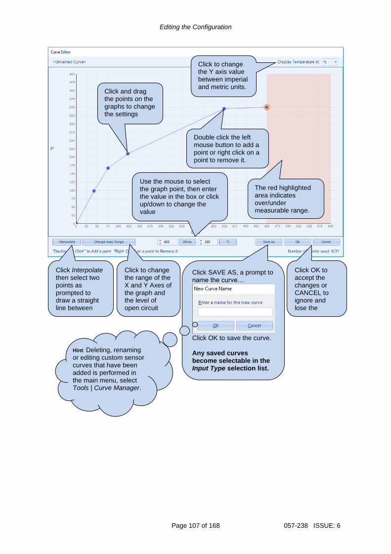
Editing the Configuration
Page 107 of 168 057-238 ISSUE: 6
Click and drag the points on the graphs to change the settings
Use the mouse to select the graph point, then enter the value in the box or click up/down to change the value
Click OK to accept the changes or CANCEL to ignore and lose the changes.
Click SAVE AS, a prompt to name the curve…
Click OK to save the curve. Any saved curves become selectable in the Input Type selection list.
Hint: Deleting, renaming or editing custom sensor curves that have been added is performed in the main menu, select Tools | Curve Manager.
Click Interpolate then select two points as prompted to draw a straight line between them.
Click to change the range of the X and Y Axes of the graph and the level of open circuit detection
Double click the left mouse button to add a point or right click on a point to remove it.
The red highlighted area indicates over/under measurable range.
Click to change the Y axis value between imperial and metric units.

Editing the Configuration
057-238 ISSUE: 6 Page 108 of 168
2.11.1.3 DIGITAL INPUTS The Digital Inputs section is subdivided into smaller sections. Select the required section with the mouse.

Editing the Configuration
Page 109 of 168 057-238 ISSUE: 6
2.11.1.3.1 DIGITAL INPUTS
Parameter Description
Function Select the input function to activate when the relevant terminal is energised. See section entitled Input Functions for details of all available functions
Polarity Select the digital input polarity: Close to Activate: the input function is activated when the relevant terminal is connected. Open to Activate: the input function is activated when the relevant terminal is disconnected.
Action NOTE: For details of these, see the section entitled Alarm Types
elsewhere in this document.
Select the type of alarm required from the list: Electrical Trip Indication Warning
Arming NOTE: For details of these, see the section entitled Alarm Arming
elsewhere in this document.
Select when the input becomes active: Active From Mains Parallel Always Never
LCD Display The text that is displayed on the module’s LCD when the input activates and generates an alarm.
Activation Delay This is used to give a delay on acceptance of the input. Useful for liquid level switches or to mask short term operations of the external switch device.
As this example shows a predefined function, these parameters are greyed out as they are not applicable.

Editing the Configuration
057-238 ISSUE: 6 Page 110 of 168
2.11.1.3.2 ANALOGUE INPUTS
NOTE: An analogue input is only configurable as a digital input if it has been configured as Digital Input, refer to section entitled Analogue Input Configuration elsewhere in this document for further details.
Parameter Description
Function Select the input function to activate when the relevant terminal is energised. See section entitled Input Functions for details of all available functions
Polarity Select the digital input polarity: Close to Activate: the input function is activated when the relevant terminal is connected. Open to Activate: the input function is activated when the relevant terminal is disconnected.
Action NOTE: For details of these, see the section entitled Alarm Types
elsewhere in this document.
Select the type of alarm required from the list: Electrical Trip Indication Warning
Arming NOTE: For details of these, see the section entitled Alarm Arming
elsewhere in this document.
Select when the input becomes active: Active From Mains Parallel Always Never
LCD Display The text that is displayed on the module’s LCD when the input activates and generates an alarm.
Activation Delay This is used to give a delay on acceptance of the input. Useful for liquid level switches or to mask short term operations of the external switch device.

Editing the Configuration
Page 111 of 168 057-238 ISSUE: 6
2.11.2 DSE2131 INPUT MODULES Select the DSENet ID of the input expansion to be configured. The ID of the expansion module is set by rotary decimal switch accessible under the removable cover of the device.
The following options are then shown: 2131 Expansion Enable
Parameter Description
Expansion Enabled = The expansion module with the selected ID is not enabled. = The expansion module with the selected ID is enabled. If the expansion module is not connected / detected by the module, the module generates an Exp. Unit Failure alarm with the configured Link Lost Alarm Action severity.
2131 Expansion Inputs The Expansion Unit page is then subdivided into smaller sections. Select the required section with the mouse.

Editing the Configuration
057-238 ISSUE: 6 Page 112 of 168
2.11.2.1 ANALOGUE INPUT CONFIGURATION
Input Configuration
Parameter Description
Analogue Input A to J Select what the analogue input is to be used for: Not Used: The analogue input is disabled Digital Input: Configured on the 2131/Digital Inputs pages Flexible Analogue: Configured on the 2131/Analogue Inputs pages

Editing the Configuration
Page 113 of 168 057-238 ISSUE: 6
2.11.2.2 ANALOGUE INPUTS
NOTE: An analogue input is only configurable as a flexible sensor if it has been configured as Flexible Analogue, refer to section entitled Analogue Input Configuration elsewhere in this document for further details.
Sensor Description
Parameter Description
Sensor Name Enter the Sensor Name, this text is shown on the module display when viewing the instrument.
Input Type
Parameter Description
Input Type Select the sensor type and curve from a pre-defined list or create a user-defined curve Resistive: for sensors with maximum range of 0 Ω to 1920 Ω Current: for sensors with maximum range of 0 mA to 20 mA Voltage: for sensors with maximum range of 0 V to 10 V Percentage: The input is configured as a percentage sensor Pressure: The input is configured as a pressure sensor Temperature: The input is configured as a temperature sensor
Parameter descriptions are continued overleaf…

Editing the Configuration
057-238 ISSUE: 6 Page 114 of 168
Sensor Alarms
Parameter Description
Alarm Arming Select when the alarm becomes active: Always Active From Mains Parallel Never
Low Alarm Enable
= The Alarm is disabled. = The Low Alarm activates when the measured quantity drops below the Low Alarm setting.
Low Alarm Action NOTE: For details of these, see the section entitled Alarm Types
elsewhere in this document.
Select the type of alarm required from the list: Electrical Trip
Low Pre-Alarm Enable
= The Pre-Alarm is disabled. = The Low Pre-Alarm is active when the measured quantity drops below the Low Pre-Alarm Trip setting. The Low Pre-Alarm is automatically reset when the measured quantity rises above the configured Low Pre-Alarm Return level.
Low Alarm String The text that is displayed on the module’s LCD when the Low Alarm or Low Pre-Alarm activates.
High Pre-Alarm Enable
= The Pre-Alarm is disabled. = The High Pre-Alarm is active when the measured quantity rises above the High Pre-Alarm Trip setting. The High Pre-Alarm is automatically reset when the measured quantity falls below the configured High Pre-Alarm Return level.
High Alarm Enable
= The Alarm is disabled. = The High Alarm is active when the measured quantity rises above the High Alarm setting.
High Alarm Action NOTE: For details of these, see the section entitled Alarm Types
elsewhere in this document.
Select the type of alarm required from the list: Electrical Trip
High Alarm String The text that is displayed on the module’s LCD when the High Alarm or High Pre-Alarm activates.

Editing the Configuration
Page 115 of 168 057-238 ISSUE: 6
2.11.2.3 DIGITAL INPUTS
NOTE: An analogue input is only configurable as a digital input if it has been configured as Digital Input, refer to section entitled Analogue Input Configuration elsewhere in this document for further details.
Parameter descriptions are overleaf…
As this example shows a predefined function, these parameters are greyed out as they are not applicable.

Editing the Configuration
057-238 ISSUE: 6 Page 116 of 168
Parameter Description
Function Select the input function to activate when the relevant terminal is energised. See section entitled Input Functions for details of all available functions
Polarity Select the digital input polarity: Close to Activate: The input function is activated when the relevant terminal is connected. Open to Activate: The input function is activated when the relevant terminal is disconnected.
Action NOTE: For details of these, see the section entitled Alarm Types
elsewhere in this document.
Select the type of alarm required from the list: Electrical Trip Indication Warning
Arming NOTE: For details of these, see the section entitled Alarm Arming
elsewhere in this document.
Select when the input becomes active: Active From Mains Parallel Always Never
LCD Display The text that is displayed on the module’s LCD when the input activates and generates an alarm.
Activation Delay This is used to give a delay on acceptance of the input. Useful for liquid level switches or to mask short term operations of the external switch device.
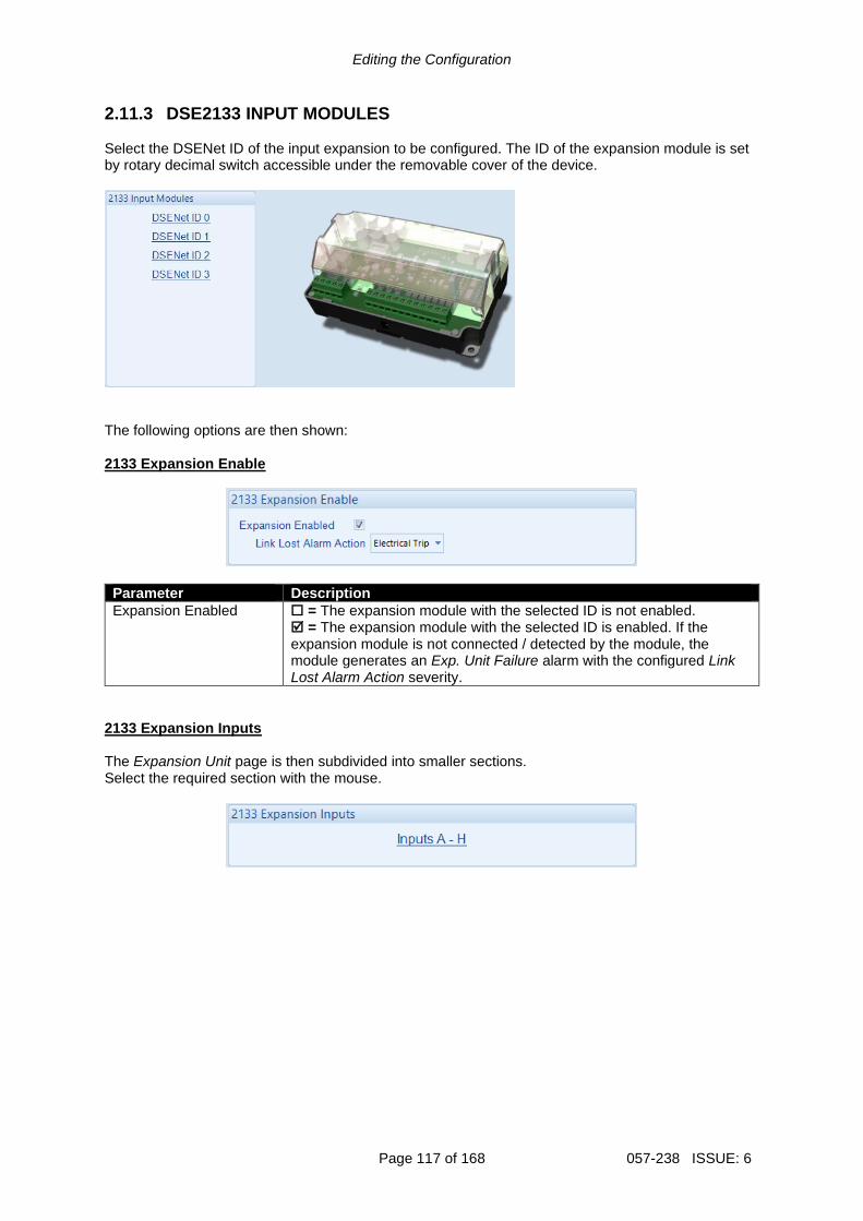
Editing the Configuration
Page 117 of 168 057-238 ISSUE: 6
2.11.3 DSE2133 INPUT MODULES Select the DSENet ID of the input expansion to be configured. The ID of the expansion module is set by rotary decimal switch accessible under the removable cover of the device.
The following options are then shown: 2133 Expansion Enable
Parameter Description
Expansion Enabled = The expansion module with the selected ID is not enabled. = The expansion module with the selected ID is enabled. If the expansion module is not connected / detected by the module, the module generates an Exp. Unit Failure alarm with the configured Link Lost Alarm Action severity.
2133 Expansion Inputs The Expansion Unit page is then subdivided into smaller sections. Select the required section with the mouse.

Editing the Configuration
057-238 ISSUE: 6 Page 118 of 168
2.11.3.1 ANALOGUE INPUTS
NOTE: An analogue input is only configurable as a flexible sensor if it has been configured as Flexible Analogue, refer to section entitled Analogue Input Configuration elsewhere in this document for further details.
Sensor Description
Parameter Description
Sensor Name Enter the Sensor Name, this text is shown on the module display when viewing the instrument.
Input Type
Parameter Description
Input Type Select the sensor type from the pre-defined list: 2 Wire PT100 3 Wire PT100 Type J (Thermocouple) Type K (Thermocouple)
Parameter descriptions are continued overleaf…

Editing the Configuration
Page 119 of 168 057-238 ISSUE: 6
Sensor Alarms
Parameter Description
Alarm Arming Select when the alarm becomes active: Always Active From Mains Parallel Never
Low Alarm Enable
= The Alarm is disabled. = The Low Alarm activates when the measured quantity drops below the Low Alarm setting.
Low Alarm Action NOTE: For details of these, see the section entitled Alarm Types
elsewhere in this document.
Select the type of alarm required from the list: Electrical Trip
Low Pre-Alarm Enable
= The Pre-Alarm is disabled. = The Low Pre-Alarm is active when the measured quantity drops below the Low Pre-Alarm Trip setting. The Low Pre-Alarm is automatically reset when the measured quantity rises above the configured Low Pre-Alarm Return level.
Low Alarm String The text that is displayed on the module’s LCD when the Low Alarm or Low Pre-Alarm activates.
High Pre-Alarm Enable
= The Pre-Alarm is disabled. = The High Pre-Alarm is active when the measured quantity rises above the High Pre-Alarm Trip setting. The High Pre-Alarm is automatically reset when the measured quantity falls below the configured High Pre-Alarm Return level.
High Alarm Enable
= The Alarm is disabled. = The High Alarm is active when the measured quantity rises above the High Alarm setting.
High Alarm Action NOTE: For details of these, see the section entitled Alarm Types
elsewhere in this document.
Select the type of alarm required from the list: Electrical Trip
High Alarm String The text that is displayed on the module’s LCD when the High Alarm or High Pre-Alarm activates.
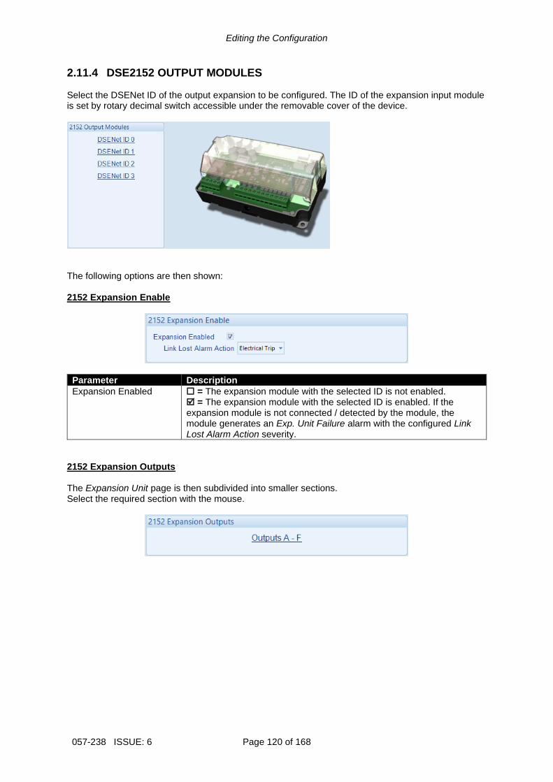
Editing the Configuration
057-238 ISSUE: 6 Page 120 of 168
2.11.4 DSE2152 OUTPUT MODULES Select the DSENet ID of the output expansion to be configured. The ID of the expansion input module is set by rotary decimal switch accessible under the removable cover of the device.
The following options are then shown: 2152 Expansion Enable
Parameter Description
Expansion Enabled = The expansion module with the selected ID is not enabled. = The expansion module with the selected ID is enabled. If the expansion module is not connected / detected by the module, the module generates an Exp. Unit Failure alarm with the configured Link Lost Alarm Action severity.
2152 Expansion Outputs The Expansion Unit page is then subdivided into smaller sections. Select the required section with the mouse.

Editing the Configuration
Page 121 of 168 057-238 ISSUE: 6
2.11.4.1 ANALOGUE OUTPUTS Output Configuration
Parameter Description
Output Name Enter the Output Name, this text is shown on in the SCADA section when viewing the output.
Output Type
Parameter Description
Source Select the parameter that is to be mapped to the analogue output.
Curve Select the output type and curve from a pre-defined list or create a user-defined curve Current: for sensors with maximum range of 0 mA to 20 mA Voltage: for sensors with maximum range of 0 V to 10 V
Click to edit the ‘output curve’. See section entitled Editing the Output Curve.

Editing the Configuration
057-238 ISSUE: 6 Page 122 of 168
2.11.4.2 CREATING / EDITING THE OUTPUT CURVE While the DSE Configuration Suite holds specifications for the most used output ranges, occasionally it is required that the expansion module’s output be connected to a none standard device. To aid this process, a curve editor is provided.
When creating a new sensor curve the measurement quantity and measured parameter are required.
Parameter Description
Y-Axis (Source)
The parameter measured by the DSE module that is to be mapped to the output.
X-Axis (Output)
Select the electrical quantity that the sensor outputs. Current (mA): For an output current within a range 0 mA to 20 mA Voltage (Volt): For an output voltage within a range of 0 V to 10 V
Curve creation / editor descriptions are continued overleaf…
Click to edit the selected curve or create a curve if one is not selected.
The source and curve that is to be used by the analogue output or edited.
Click to begin creating the new curve
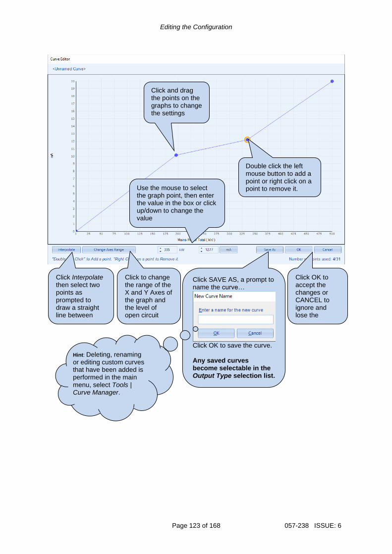
Editing the Configuration
Page 123 of 168 057-238 ISSUE: 6
Click and drag the points on the graphs to change the settings
Use the mouse to select the graph point, then enter the value in the box or click up/down to change the value
Click OK to accept the changes or CANCEL to ignore and lose the changes.
Click SAVE AS, a prompt to name the curve…
Click OK to save the curve. Any saved curves become selectable in the Output Type selection list.
Hint: Deleting, renaming or editing custom curves that have been added is performed in the main menu, select Tools | Curve Manager.
Click Interpolate then select two points as prompted to draw a straight line between them.
Click to change the range of the X and Y Axes of the graph and the level of open circuit detection
Double click the left mouse button to add a point or right click on a point to remove it.

Editing the Configuration
057-238 ISSUE: 6 Page 124 of 168
2.11.5 DSE2157 RELAY MODULES Select the DSENet ID of the output expansion to be configured. The ID of the expansion module is set by rotary decimal switch accessible under the removable cover of the device.
The following options are then shown: 2157 Expansion Enable
Parameter Description
Expansion Enabled = The expansion module with the selected ID is not enabled. = The expansion module with the selected ID is enabled. If the expansion module is not connected / detected by the module, the module generates an Exp. Unit Failure alarm with the configured Link Lost Alarm Action severity.
Relay Outputs (Normally Open / Changeover)
Parameter Description
Source Select the output source to control the state of the output See section entitled Output Sources for details of all available functions
Polarity Select the digital input polarity: Energise: When the output source is true, the output activates. De-Energise: When the output source is true, the output deactivates.

Editing the Configuration
Page 125 of 168 057-238 ISSUE: 6
2.11.6 DSE2548 ANNUCIATOR MODULES Select the DSENet ID of the LED expansion to be configured. The ID of the expansion input module is set by rotary decimal switch accessible on the rear of the device.
The following options are then shown: 2548 Expansion Enable
Parameter Description
Expansion Enabled
= The expansion module with the selected ID is not enabled. = The expansion module with the selected ID is enabled. If the expansion module is not connected / detected by the module, the module generates an Exp. Unit Failure alarm with the configured Link Lost Alarm Action severity.
Sounder Configuration
Parameter Description
Follow Main Unit
= If the mute / lamp test button is pressed, other DSE2548 modules and the host module does not respond to this. = If the mute / lamp test button is pressed, other DSE2548 modules configured to Follow main unit and the host module also lamp test / mute their alarm and vice-versa.
Sounder Enabled
= The DSE2548 internal sounder does not annunciate on a fault condition becoming active. = The DSE2548 internal sounder annunciates on a fault condition becoming active.
Parameter descriptions are continued overleaf…

Editing the Configuration
057-238 ISSUE: 6 Page 126 of 168
LED Indicators
Parameter Description
Source Select the output source to control the state of the output See section entitled Output Sources for details of all available functions
Polarity Select the digital input polarity: Energise: When the output source is true, the output activates. De-Energise: When the output source is true, the output deactivates.
Annunciator Insert Card
Allows the user to create and print the custom text insert cards for the LEDs.

Editing the Configuration
Page 127 of 168 057-238 ISSUE: 6
2.11.7 BATTERY CHARGERS Select the DSENet ID of the battery charger to be configured. The ID of the expansion module is set by configuration of the device.
The following options are then shown: DSENet ID
Parameter Description
Enable = The battery charger with the selected ID is not enabled. = The battery charger with the selected ID is enabled. If the expansion module is not connected / detected by the module, the module generates an Exp. Unit Failure alarm with the configured Link Lost Alarm Action severity.
Modbus Slave ID The Slave ID used to address the battery charger via the host module’s RS485 when using the host module as a MODBUS RTU pass through.
Display Instrumentation
= The battery chargers’ information is not shown on the host module’s display. = The battery charger information is shown on the host module’s display.
Charger Name Enter the Charger Name, this text is shown on the module display when viewing the battery charger instrumentation

Editing the Configuration
057-238 ISSUE: 6 Page 128 of 168
Charger Shutdown Alarms
Parameter Description
Enable = The DSE module does not display any shutdown alarms from the battery charger. = The DSE module displays shutdown alarms from the battery charger with the configured action.
Alarm String The text that is displayed on the module’s LCD when the DSE module detects a shutdown fault from the battery charger.
Charger Warning Alarms
Parameter Description
Enable = The DSE module does not display any warning alarms from the battery charger. = The DSE module displays warnings alarms from the battery charger with the configured action.
Alarm String The text that is displayed on the module’s LCD when the DSE module detects a warning fault from the battery charger.

Editing the Configuration
Page 129 of 168 057-238 ISSUE: 6
2.12 ADVANCED The Advanced page is subdivided into smaller sections. Select the required section with the mouse.

Editing the Configuration
057-238 ISSUE: 6 Page 130 of 168
2.12.1 ADVANCED OPTIONS Out of Sync
Parameter Description
Out of Sync Angle
During parallel operation, the phase of both supplies is monitored. Being in parallel means that the phase difference is zero degrees (0 º) between the two supplies. If the angle exceeds the Out of Sync Angle for longer than the duration of the Out of Sync Timer, an alarm is generated with the configured Action. Select the type of alarm required from the list: Auxiliary Mains Failure Electrical Trip Warning
Troubleshooting Out of Sync This section describes the most common causes for an Out of Sync alarm:
• The switchgear does not close quickly enough. Ensure the switchgear closes within 100 ms of receiving the close signal.
• The Out of Sync timer is set too low. If this timer is raised away from the factory setting of 200 ms (0.2 s), ensure the consequences are fully understood.
• Something external has caused the switchgear to open, or has prevented it from closing. Typical examples are external G59 relays and other equipment operating directly on the switchgear to open it.
• The switchgear wiring ‘logic’ is not correct, causing the switchgear to ‘fire through’, where it triggers the close mechanism, but the switchgear doesn’t actually mechanically close, it re-opens again.
Other Timers
Parameter Description
Synchronisation Delay
Delays the synchronising process to allow the Generator Bus to stabilise and power parasitic loads or transformers (for instance) before the synchronising process begins.
Mains Decoupling Supervision
Delays the activation of the inbuilt Mains Decoupling detection when Bus switchgear closes in in parallel with the mains. Upon closing into parallel, the timer is activated. After the timer has expired, the Mains decoupling protection becomes active.
Interlock Override Off
Timer to delay the Interlock Override de-energising once a breaker has opened.

Editing the Configuration
Page 131 of 168 057-238 ISSUE: 6
Test Mode
Parameter Description
Run Mode Configures the operation of the Test button as: Island Mode: The module performs the start sequence and transfers all the load to the Generator Bus. The Mains switchgear is left open and the Generator Bus runs in island mode. Parallel Mode: The module performs the start sequence and synchronises the generators Bus to the Mains to allow long term parallel operation; peak lopping when set to Mains Mode, or fixed export / base load when in Bus Mode.
Ramp
Parameter Description
Alternative Ramping Scheme
NOTE: The Maximum Load Level are configured within the SCADA section. For further details, refer to section entitled Load Levels contained within the SCADA section elsewhere within this document.
= In Bus Mode, when the Mains returns the Generator Bus ramps up to the Maximum Load Level before ramping off to the Mains. = In Bus Mode, when the Mains returns the Generator Bus ramps off from its current load level to the Mains
Dead Bus Synchronising
Parameter Description
Enable = All synchronising is performed ‘the traditional’ way by achieving a slip frequency and waiting for the voltage, frequency and phase to be within configured windows = The Dead Bus Synchronising feature is activated as configured below.
Sync Mode
Always: Dead Bus sync is always used when the generators are required to be on line and in the Auto mode (Dead Bus sync does not operate in Manual mode under any circumstance). Disabled: The feature is not active On Input: Dead Bus sync is used when a digital input configured for Remote Start Dead Bus Synchronising is active. On Mains Failure: The generators are started in dead Bus sync whenever the Mains failure occurs.
Start Delay Time delay used at start up to ensure the start request is not simply a fleeting request.

Editing the Configuration
057-238 ISSUE: 6 Page 132 of 168
Manual Island Mode Bus Limits
NOTE: The Manual Island Mode Bus Limits feature is only applicable on the DSE8660 MKII when it is in Island mode or in Manual mode and generators running in island.
NOTE: The DSE module does not use the Manual Island Mode Bus Limits settings for the normal synchronisation and load share operation.
In certain applications it is required to ‘manually’ synchronise the generators bus to an external source ‘mains’ then to manually control the mains switchgear to parallel the generators bus with the mains. In this instance the DSE8660 MKII’s Bus Voltage Adjust and the Bus Frequency Adjust functions must be used to control the bus voltage and bus frequency levels when the generators are running in island. The Bus Voltage Adjust and the Bus Frequency Adjust levels are configured from the PLC Editor or through Modbus communication by writing to the Bus Voltage Adjust and the Bus Frequency Adjust GenComm registers. The Manual Island Mode Bus Limits feature, applicable when generators running in island mode only, is to set limits to the bus voltage bias and the bus frequency bias that the DSE8660 MKII has to control the DSE8610 MKII generators over the MSC. The configuration of these settings depend on the generators’ control ranges capabilities. For example, if in a system one or more of the generators is only able to be controlled by +/-30 volts, then the Manual Voltage Limit must be configured to 30.0 Volt. In this way the DSE8660 MKII does not request more than what that generator is able to accept. To control the bus voltage and the bus frequency through the Bus Voltage Adjust and the Bus Frequency Adjust functions, it is first required to enable the Manual Bus Adjust from the PLC Editor’s Override Gencomm functionality. It is also possible to enable the Manual Bus Adjust through GenComm. The DSE8660 MKII uses the Manual Island Mode Bus Limits only when all the following conditions are satisfied:
• The DSE8660 MKII must be in Island Mode or in Manual Mode and not in parallel with the mains.
• The DSE8660 MKII must have the Control over the DSE8610 MKII modules.
• The Manual Bus Adjust must be set to active. Refer to the section entitled PLC elsewhere in this document for details on how to use the PLC Editor.
Parameter Description
Manual Voltage Limit
This is the maximum voltage that the DSE8660 MKII increases or decreases around the Bus Nominal Voltage when requested to control the DSE8610 MKII generators’ bus voltage through the MSC whilst running in island.
Manual Frequency Limit
This is the maximum frequency that the DSE8660 MKII increases or decreases around the Bus Nominal Frequency when requested to control the DSE8610 MKII generators’ bus frequency through the MSC whilst running in island.

Editing the Configuration
Page 133 of 168 057-238 ISSUE: 6
2.12.2 PLC
NOTE: For further details and instructions on the PLC Editor, refer to DSE Publication: 057-314 Advanced PLC Software Manual which is found on our website: www.deepseaelectronics.com
NOTE: For the earlier software versions pre-V5 of the module, refer to DSE Publication: 057-175 PLC Programming Guide which is found on our website: www.deepseaelectronics.com
Click to open the PLC Editor, then the PLC Editor opens as shown below.

Editing the Configuration
057-238 ISSUE: 6 Page 134 of 168
2.12.3 CONFIGURABLE GENCOMM PAGES 166 TO 169
For advanced MODBUS users of the controller, configurable Gencomm pages are available. The intention is to allow the user to create personal collections of data in subsequent registers to minimise the number of MODBUS reads required by the master, and hence speed up data collection. All configurable Gencomm registers are 32-bit unsigned format.
The configurable MODBUS pages are:
Page Hex Address Decimal Address
166 A600 42496
167 A700 42752
168 A800 43008
169 A900 43264
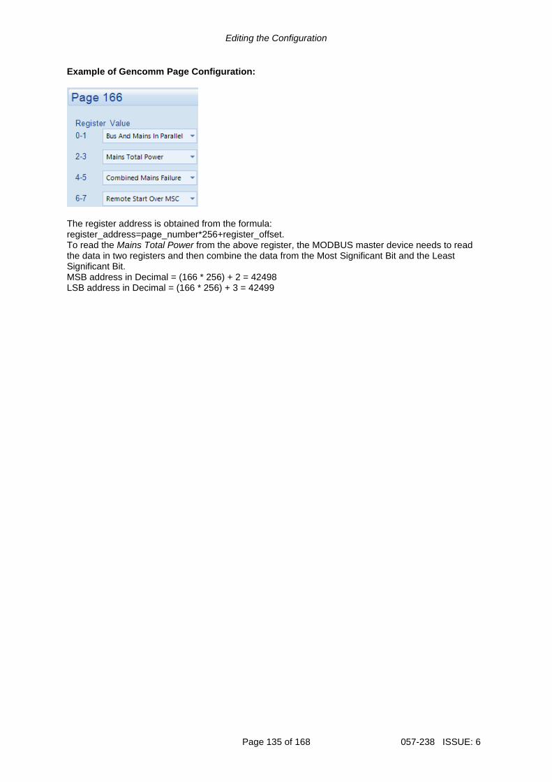
Editing the Configuration
Page 135 of 168 057-238 ISSUE: 6
Example of Gencomm Page Configuration:
The register address is obtained from the formula: register_address=page_number*256+register_offset. To read the Mains Total Power from the above register, the MODBUS master device needs to read the data in two registers and then combine the data from the Most Significant Bit and the Least Significant Bit. MSB address in Decimal = (166 * 256) + 2 = 42498 LSB address in Decimal = (166 * 256) + 3 = 42499

Editing the Configuration
057-238 ISSUE: 6 Page 136 of 168
2.12.4 CONFIGURABLE EDITOR SCREENS The Configurable Editor Screens enables the user to select six parameters to be editable through the module display. The editing of these parameters is not protected by the PIN (if enabled).
Parameter Description
Editable Item 1 to 6 Select the required parameter to be shown and be editable from the module’s screen.

SCADA
Page 137 of 168 057-238 ISSUE: 6
3 SCADA SCADA stands for Supervisory Control And Data Acquisition and is provided both as a service tool and also as a means of monitoring / controlling the Generator Bus. As a service tool, the SCADA pages are to check the operation of the controller’s inputs and outputs as well as checking the Mains operating parameters.
When connection is made…
The SCADA page is subdivided into smaller sections. Select the required section with the mouse.
Click to close the connection to the module
The Module’s firmware revision number
Click to open the connection to the module. If no module is connected, the SCADA opens to show the screens for the type of module currently open in the configuration.

SCADA
057-238 ISSUE: 6 Page 138 of 168
3.1 MAINS IDENTITY This section displays the module’s configuration settings for Site ID and Genset ID. For further details on how to configure these items, refer to section entitled Communications Options elsewhere within this document.
3.2 MIMIC This section provides a mimic of the module’s fascia and allows the operator to change the control mode of the module. For information in regards to operating the DSE module, refer to DSE publication: 057-259 DSE8660 MKII Operation Manual which is found on the DSE website: www.deepseaelectronics.com
Click the mimic buttons to control the module remotely
Hint: Buttons may not operate if this has been locked out by the Access Permissions security feature of the
Configuration Suite software. Refer to the system supplier for details.

SCADA
Page 139 of 168 057-238 ISSUE: 6
3.3 DIGITAL INPUTS This section displays the status of the module’s digital inputs and the functions they are configured for. For further details on how to configure these items, refer to section entitled Digital Inputs elsewhere within this document.
State of the input (open or closed to battery negative)
Shows if the input channel is active or not. This input is open and not active. The input is configured to be Close to Activate

SCADA
057-238 ISSUE: 6 Page 140 of 168
3.4 DIGITAL OUTPUTS This section displays the status of the module’s digital outputs and the functions they are configured for. For further details on how to configure these items, refer to section entitled Digital Outputs elsewhere within this document.
State of the output (open or closed)
Shows if the output channel is active or not. This output is closed and is active. The output is configured to be Close Mains Energise. As the module wants the Mains switchgear closed, the output is Energised.
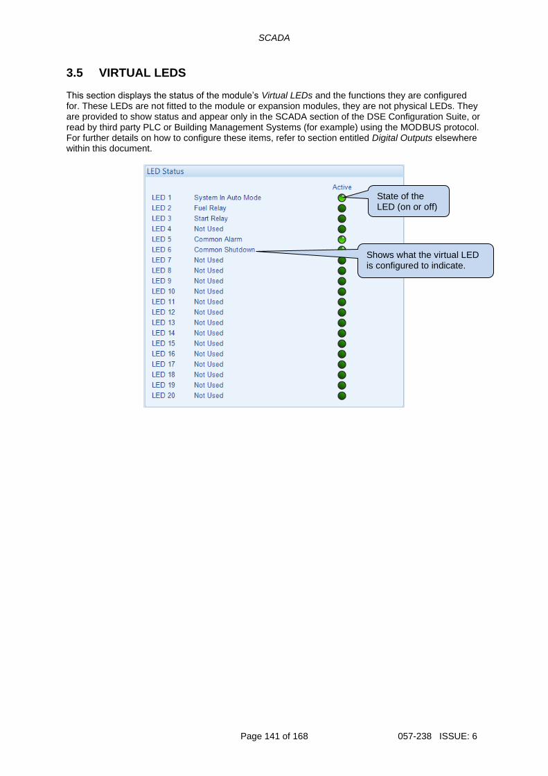
SCADA
Page 141 of 168 057-238 ISSUE: 6
3.5 VIRTUAL LEDS This section displays the status of the module’s Virtual LEDs and the functions they are configured for. These LEDs are not fitted to the module or expansion modules, they are not physical LEDs. They are provided to show status and appear only in the SCADA section of the DSE Configuration Suite, or read by third party PLC or Building Management Systems (for example) using the MODBUS protocol. For further details on how to configure these items, refer to section entitled Digital Outputs elsewhere within this document.
State of the LED (on or off)
Shows what the virtual LED is configured to indicate.

SCADA
057-238 ISSUE: 6 Page 142 of 168
3.6 BUS The Bus section is subdivided into smaller sections. Select the required section with the mouse.
3.6.1 FREQUENCY AND VOLTAGES This section displays the module’s measurement of the Bus supply.

SCADA
Page 143 of 168 057-238 ISSUE: 6
3.6.2 LOAD This section displays the module’s measurement of the Load derived from the Load CT.

SCADA
057-238 ISSUE: 6 Page 144 of 168
3.6.3 MSC LINK
NOTE: These settings are not saved within the module’s configuration file. They are stored in a different memory area and not transferred with the configuration file. The Backup Module feature transfers both the configuration file AND the settings of the MSC Link, Sync and Load Levels page.
Bus
Parameter Description
Set On The Bus The number of DSExx10 controllers that are connected on the MSC link.
Sets On Load The number of DSExx10 controllers that are connected on the MSC link and closed onto the Generator Bus.
Mains Controllers On The Bus
The number of DSExx60 and DSExx80 controllers that are connected on the MSC link.
Mains
Parameter Description
MSC ID Select the MSC ID of the DSE module’s MSC port. Every module connected on the MSC link must have a unique MSC ID. The MSC ID is automatically set when all the modules are powered up “one at a time”. If all the modules a powered up together, this may result in the MSC ID Error alarm activating. Manually setting the MSC ID allows this alarm to be reset and prevents this from occurring.
Priority NOTE: DSExx60 and DSExx80 modules cannot have the same MSC
Priority Number.
Select the Priority of the module. The priority dictates which DSExx60 performs the change over from Mains to Generator Bus (and vice versa) first.
Commissioning Screen
Parameter Description
Enable = Commissioning screens are not shown on the module display = The commissioning screens are shown at the bottom of the Bus section on the module display. These pages are useful for the commissioning and troubleshooting of a load share system.
Shows if the Commissioning Screen is active or not.

SCADA
Page 145 of 168 057-238 ISSUE: 6
3.6.4 SYNC
NOTE: These settings are not saved within the module’s configuration file. They are stored in a different memory area and not transferred with the configuration file. The Backup Module feature transfers both the configuration file AND the settings of the MSC Link, Sync and Load Levels page.
Frequency Synchroniser
Parameter Description
Slip Frequency This is the frequency difference between the Generator Bus and the Mains which the module adjusts to during synchronising. This is done to match the phase of the Generator Bus supply to Mains supply. The phase of the supplies then drifts in and out of synchronism at a rate of 1/Slip Frequency times per second. e.g. with a Slip Frequency of 0.2 Hz, the supplies are in phase once every five seconds.
Load Share
Parameter Description
Stability (I) The setting for the Stability (I) of the control loop used for control the DSExx10’s kW power production. In general, lower setting results in slow kW control, but too high a setting may cause instability (hunting). If this occurs, lower the stability setting.
Reactive Load
Parameter Description
Stability (I) The setting for the Stability (I) of the control loop used for control the DSExx10’s kvar power production. In general, lower setting results in slow kvar control, but too high a setting may cause instability (hunting). If this occurs, lower the stability setting.

SCADA
057-238 ISSUE: 6 Page 146 of 168
3.6.5 LOAD LEVELS Levels
NOTE: The Load Level settings only have effect when the Generator Bus is in parallel with the mains.
For further details on how to configure the different power modes and their operation, refer to section entitled Power Control and Voltage and Reactive Power Control elsewhere within this document.
Parameter Description
Mode: Bus Using the Remote Start on Load input to the module, the Generator Bus is instructed to go into continuous parallel operation with the mains. This may be required to only occur during specified times of the day. When the module is set to Bus Mode, this causes the Generator Bus to produce a fixed (base) level of Active Power (kW) and Reactive Power (kvar) against the Mains when in continuous parallel operation.
With Bus Mode, care must be taken if exporting power to the Mains supply is not allowed. For instance, if the Maximum kW Level is set to 100 kW and the site load is 75 kW, the Generator Bus exports 25 kW into the Mains supply. The Maximum kW Level and Maximum kvar Level are a percentage of each generators capacity that is connected to the Bus. E.g. on a multi set system where each Generator is rated at 500 kW and the Maximum kW Level was set to 50%, each Generator running produces 250 kW. Therefore, the actual kW and kvar produced varies depending on how many generators are closed onto the Bus.
Sit
e L
oad
Midday Morning Evening
Maximum kW Level

SCADA
Page 147 of 168 057-238 ISSUE: 6
Parameter Description
Mode: Mains NOTE: When operating in Mains Mode, the generators are never
driven to more than 100% of their full load rating. When the generators reach 100% of their full load rating, the Insufficient Capacity alarm activates (if configured).
Using the Remote Start on Load input to the module, the Generator Bus is instructed to go into continuous parallel operation with the Mains once the Mains power exceeds the Maximum kW Level setting. This may be required to only occur during specified times of the day. When the module is set to Mains Mode, this enables the Generator Bus to provide Peaking Lopping/Shaving Parallel operation when in continuous parallel with the mains.
With Mains Mode, the Generator Bus is used to provide a variable amount of Active Power (kW) to maintain the Mains import/export levels to the configured Maximum kW Level. The Maximum kW Level and Maximum kvar Level are a percentage the Mains rating. E.g. If the Mains rating was configured as 250 kW, the Generator Bus would supply the difference between 250 kW and total connected load. If the load was lower than 250 kW, Generator Bus comes off load performs a controlled stop.
Power Control Mode NOTE: For further information on these operating modes, refer to
section entitled Power Control elsewhere within this document.
Allows selection of the Power Control Mode when running in Bus Mode. This is also selectable by activation of a configured digital input or via the Running Editor.
Reactive Power Control Mode NOTE: For further information on these operating modes, refer to
section entitled Voltage and Reactive Power Control elsewhere within this document.
Allows selection of the Reactive Power Control Mode when running in Bus Mode. This is also selectable by activation of a configured digital input or via the Running Editor.
Midday Morning Evening
Sit
e L
oad
Maximum kW Level

SCADA
057-238 ISSUE: 6 Page 148 of 168
Parameter Description
Maximum Load Level NOTE: When in Bus Mode if Maximum kW Level is greater than
the load, power is exported to the mains. If required, enable the module’s Mains Export Power alarm to protect against undesired power export.
The operation of this setting depends on the parallel mode selected: Bus: The percentage of total kW the Generator Bus to produce whilst in continuous parallel with the mains. Mains: The percentage of the Mains kW rating the Generator Bus is to maintain whilst in continuous parallel.
Maximum var Level NOTE: When in Bus Mode if Maximum kvar Level is greater than
the load, power is exported to the mains.
The percentage of total kvar the Generator Bus to produce whilst in continuous parallel with the mains.
Power Factor The power factor the Generator Bus is to produce whilst in continuous parallel with the mains.
Ramp Rates
NOTE: These adjustable parameters do not change the module’s configuration settings. These settings enable the user to change the values dynamically via SCADA or the module’s internal PLC based on operating requirements.
Parameter Description
Ramp Up Rate The rate at which the Generator Bus is ramped onto the load.
Ramp Down Rate The rate at which the Generator Bus is ramped off the load.
Power Ramp on Setpoint Change
When changing between Power Control modes or changing the set point, the Ramp Rate defines how fast the Generator Bus power changes in percentage points per second.
Reactive Power Ramp on Setpoint Change
When changing between Reactive Power Control modes or changing the set point, the Ramp Rate defines how fast the Generator Bus power changes in percentage points per second.

SCADA
Page 149 of 168 057-238 ISSUE: 6
3.7 MAINS The Mains section is subdivided into smaller sections. Select the required section with the mouse.
3.7.1 FREQUENCY AND VOLTAGES This section displays the module’s measurement of the Mains frequency, voltage and current supply.

SCADA
057-238 ISSUE: 6 Page 150 of 168
3.7.2 POWER This section displays the module’s measurement of the Power the Mains is supplying.

SCADA
Page 151 of 168 057-238 ISSUE: 6
3.8 ALARMS This section displays the alarms that are currently active on the module. For information in regards to alarm descriptions, refer to DSE publication: 057-259 DSE8660 MKII Operation Manual which is found on the DSE website: www.deepseaelectronics.com. For information in regard to alarm severity, refer to section entitled Alarm Types elsewhere within this document. Alarms
Alarms that are active on the unit are grouped based on their type. For example, the Mains Failed to Close alarm appears in the Warning Alarms list because it has generated a Warning alarm type.

SCADA
057-238 ISSUE: 6 Page 152 of 168
3.9 STATUS This section displays the status information about the module.

SCADA
Page 153 of 168 057-238 ISSUE: 6
3.10 EVENT LOG This section displays the events which are recorded with the module’s event log along with the time, date in which they occurred. For further details on how what events are recorded, refer to section entitled Event Log elsewhere within this document. For information in regards to alarm descriptions, refer to DSE publication: 057-259 DSE8660 MKII Operation Manual which is found on the DSE website: www.deepseaelectronics.com.
Click to save the log to an Excel or csv file for use in an external spreadsheet program.
Click to save the log to a pdf (Adobe Acrobat) file.
Click to print the log

SCADA
057-238 ISSUE: 6 Page 154 of 168
3.11 REMOTE CONTROL This section displays and controls the status of the module’s Remote Control functions. Any of the module’s outputs, expansion outputs, LED indicators, expansion LEDs indicators or PLC Flag Tests are to be configured to Remote Control 1 to 10. They are provided to enable control using the SCADA section of the DSE Configuration Suite or by third party PLC or Building Management Systems (for example) using the MODBUS protocol. For further details on how to configure these items, refer to section entitled Digital Outputs elsewhere within this document.
State of the Remote Control (on or off)
= Remote Control is de-activated. = Remote Control is activated.
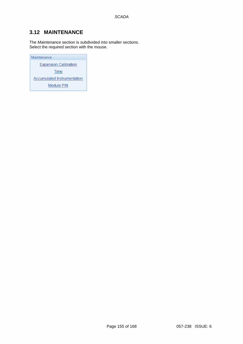
SCADA
Page 155 of 168 057-238 ISSUE: 6
3.12 MAINTENANCE The Maintenance section is subdivided into smaller sections. Select the required section with the mouse.

SCADA
057-238 ISSUE: 6 Page 156 of 168
3.12.1 EXPANSION CALIBRATION This section allows the analogue sensor inputs of the DSE2130 and DSE2131 expansion modules to be calibrated to remove inaccuracies caused by the tolerance of the sensor devices. While the Generator Bus is running, the instruments are calibrated, and reference needs to be made to a third party accurate sensing device to ensure accurate recalibration.
Click to reset all the recalibration settings back to default.
The value for the sensor as displayed on the module’s display
Adjust the slider to alter the module’s calibration for the senor

SCADA
Page 157 of 168 057-238 ISSUE: 6
3.12.2 TIME This section allows the date and time to be adjusted on the controller.
Display of the module’s current date and time
Type the new date / time or click the up and down arrows to change the settings
Click Set to adjust the module to the selected date/time.
Click Set to adjust the module to the date/time that the PC is set to.

SCADA
057-238 ISSUE: 6 Page 158 of 168
3.12.3 ACCUMULATED INSTRUMENTATION This section allows the Mains accumulated instrumentation to be adjusted on the controller.
Type the new value or click the up and down arrows to change the settings.
Click Set to adjust the module to the selected value.
Display of the module’s current value for the parameter.
Click to reset all the accumulated instrumentation counters to zero.

SCADA
Page 159 of 168 057-238 ISSUE: 6
3.12.4 MODULE PIN
CAUTION!: If the module PIN is lost or forgotten, it is no longer possible to access or make changes to the module!
This section allows the user to configure a PIN (Personal Identification Number) within the module. This PIN must be entered to access the modules Main Front Panel Configuration Editor or, when writing a configuration / changing a value in SCADA using the DSE Configuration Suite PC Software.
Enter the desired PIN and confirmation
Click to set the PIN within the module.

SCADA
057-238 ISSUE: 6 Page 160 of 168
3.13 COMMUNICATIONS INFORMATION This section displays the information about the configuration of the module’s ethernet port. For further details on how to configure the module’s ethernet port, refer to section entitled Ethernet elsewhere within this document.

SCADA
Page 161 of 168 057-238 ISSUE: 6
3.14 DATA LOG This section displays and temporarily records the instruments configured within the module’s Data Logging facility to the PC. The data which is temporarily recorded is only for the duration in which the Data Log section is viewed. For further details on how to configure these items, refer to section entitled Data Logging elsewhere within this document.
Selects the timescale of the displayed graphs. Scroll bars on the graph’s ‘x’ axis is also used to scroll the graph backwards and forwards in time.
The data is automatically collated and presented in the graphs. For example, all kW readings are displayed in the same graph, but not mixed with kvar for which are shown on a separate graph.
Zoom slider
Navigation sliders

SCADA
057-238 ISSUE: 6 Page 162 of 168
3.15 PLC
NOTE: This section is only available on the pre-version 5 software of the module. For further details and instructions on how to utilise the PLC, refer to DSE publication: 057-175 PLC Programming Guide for DSE Controllers, which is found on the DSE website: www.deepseaelectronics.com.
NOTE: On module software versions 6.1 and later, the Connect SCADA is available within the PLC Editor accessed from the main configuration’s PLC section. For further details and instructions on the PLC Editor, refer to DSE Publication: 057-314 Advanced PLC Software Manual which is found on our website: www.deepseaelectronics.com
The PLC section is subdivided into smaller sections. Select the required section with the mouse.
3.15.1 PLC LOGIC This section displays the real-time status of the PLC Logic configured within the module. This section is useful for assisting with fault finding issues relating to or caused by the PLC Logic.
Green highlighting shows the condition is True.
Live timer and counter display subject to the speed of update over the communications link
Flag State – Clear means the flag is not set.
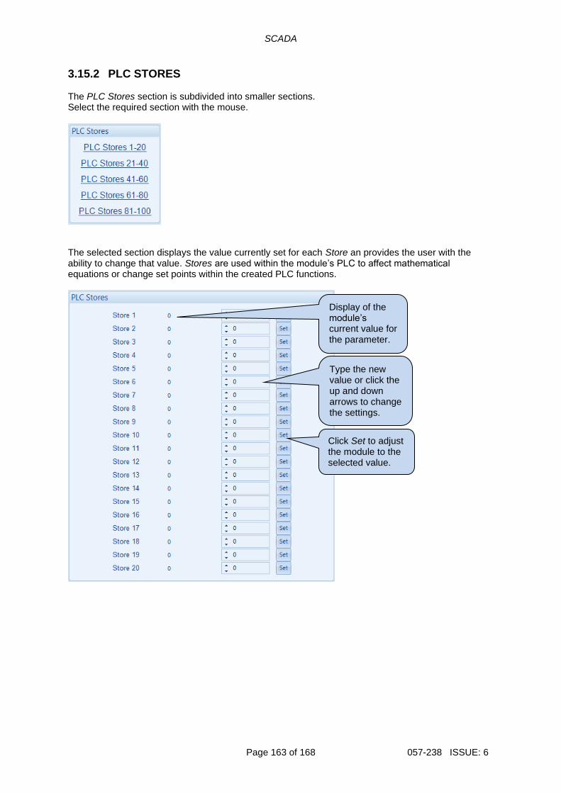
SCADA
Page 163 of 168 057-238 ISSUE: 6
3.15.2 PLC STORES The PLC Stores section is subdivided into smaller sections. Select the required section with the mouse.
The selected section displays the value currently set for each Store an provides the user with the ability to change that value. Stores are used within the module’s PLC to affect mathematical equations or change set points within the created PLC functions.
Type the new value or click the up and down arrows to change the settings.
Click Set to adjust the module to the selected value.
Display of the module’s current value for the parameter.

SCADA
057-238 ISSUE: 6 Page 164 of 168
3.16 EXPANSION The Expansion section is subdivided into smaller sections. Select the required section with the mouse.
The selected section displays the status of the expansion module’s inputs/outputs/LEDs etc and the functions they are configured for. For further details on how to configure these items, refer to section entitled Expansion in the Edit Config section elsewhere within this document. An example status of a DSE2157 Output Expansion is shown below.
State of the output (open or closed)
Shows if the output channel is active or not. This output is open and is active. The output is configured to be PLC Output Flag 6 De- Energise.
State of communication to the expansion module

Alarm Types
Page 165 of 168 057-238 ISSUE: 6
4 ALARM TYPES The protection included with the DSE control modules provides increasing levels of notification, depending upon the severity of the situation:
Alarm Type Description
Indication No audible alarm or common warning signal occurs. Indication alarms are only used to illuminate indicators, activate outputs or checked by the module’s internal PLC.
Warning Audible alarm and common alarm signal is generated. The Generator Bus continues to run. Warning alarms are used to draw the operator’s attention to a minor issue or to a problem that may escalate to an Electrical Trip if left untreated.
Electrical Trip Audible alarm and common alarm signal are generated. The Generator Bus is taken off load and the cooling timer begins, after which the set is stopped. Electrical Trip alarms are series issues that require the Generator Bus to be taken off load. As the name implies, this is often electrical faults that occur ‘after’ the load switch. The Generator Bus is allowed to cool before stopping.
Auxiliary Mains Failure The module operates as if the incoming Mains supply has fallen outside of limits, the Generator Bus is instructed to start and take the load. Deactivation of this alarm causes the module to act as the Mains has returned to within limits providing that the Mains sensing also indicates that the Mains is within limits.
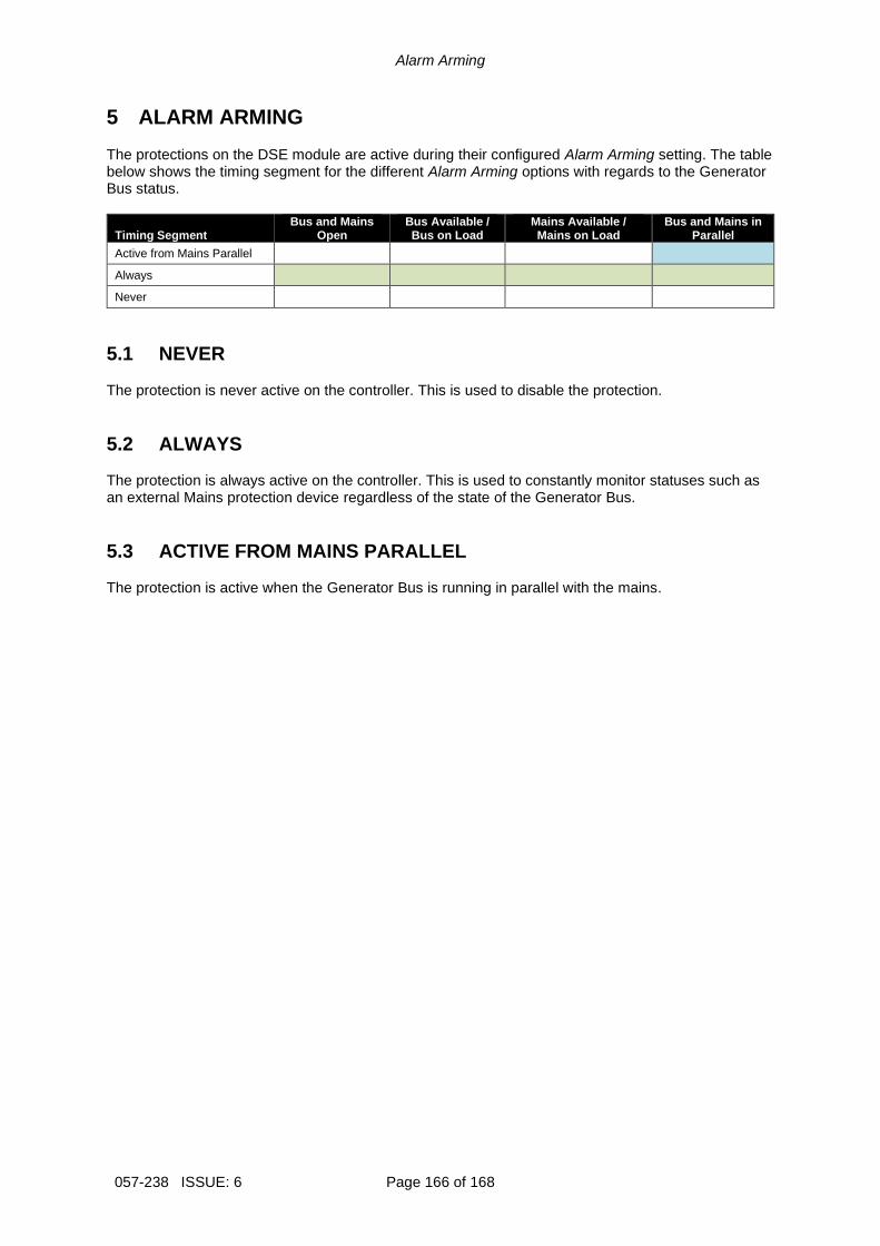
Alarm Arming
057-238 ISSUE: 6 Page 166 of 168
5 ALARM ARMING The protections on the DSE module are active during their configured Alarm Arming setting. The table below shows the timing segment for the different Alarm Arming options with regards to the Generator Bus status.
Timing Segment Bus and Mains
Open Bus Available / Bus on Load
Mains Available / Mains on Load
Bus and Mains in Parallel
Active from Mains Parallel
Always
Never
5.1 NEVER The protection is never active on the controller. This is used to disable the protection.
5.2 ALWAYS The protection is always active on the controller. This is used to constantly monitor statuses such as an external Mains protection device regardless of the state of the Generator Bus.
5.3 ACTIVE FROM MAINS PARALLEL The protection is active when the Generator Bus is running in parallel with the mains.

Page is Left Intentionally Blank

Page is Left Intentionally Blank