dsmith reference%231
TRANSCRIPT

5/17/2018 Dsmith Reference%231 - slidepdf.com
http://slidepdf.com/reader/full/dsmith-reference231 1/14
Resonate Electrical Power System
Don L. SmithPotential Energy is everywhere at all times, becoming' useful when conver
into a more practical form. There is no energy shortage, only gray matte
This energy potential is observed indirectly through the manifestation of
electromagnetic phenomenon, when intercepted and converted, becomes us
In nonlinear systems, interaction of magneticwaves amplify (conjugate)
energy, providing greater output than input. In simple form, in the piano
where three strings are struck by the hammer, the center one is impacted
and resonance activates the side strings. Resonance between the three stri
provide a sound level greater than the mput energy. Sound is a part of
electromagnetic spectrum and is subject to all that is applicable.
Useful Energy is Defined as that which is other than Ambient. ElectricaPotential relates to mass and it's acceleration. Therefore, the Earth's Mass
and Speed through space gives it an enormous electrical potential. Human
are like the bird sitting unaware on a high voltage line. In nature turbule
upsets ambient and we see electrical displays. Tampering with ambient
allows humans to convert m.agneticwaves into useful electricity.
Putting the above in focus requires a look at the Earth in general. Eachminute of each day ( 1,440 minutes ) more than 4,000 displays of lighten
occurs. Each display yields greater than 10 million volts at greater than
200,000 amperes in equivalent electromagnetic flux. This exceeds 57,600,0
million volts and 1,152,000 million amperes of electromagnetic flux each
hour period. This has been going on for more then 4 Billion Years. The
USPTO insist that the Earth's electrical field is insignificant and useless,
that converting this energy violates the laws of nature. At the same time
they issue patents wherein electromagnetic flux incoming from the Sun is
converted by Solar Cells to DC Energy. This is further converted to the
required usage. Aeromagnetic flux (in gammas) Maps-World Wide, incl
those provided by the US Department of Interior-Geological Survey, clear
shows a spread of 1,900 gamma, above Ambient present, reading instrum
flown 1,000 feet above the ( surface) source. Coulomb's Law requires the
squaring of the distance of the remote reading, times the reading for the
corrected amount. Therefore, 1,000 X 1,000 equals One Million X 1,900gamma, being 1,900 million gammas.

5/17/2018 Dsmith Reference%231 - slidepdf.com
http://slidepdf.com/reader/full/dsmith-reference231 2/14
There is a tendency to confuse gamma ray with gamma. Gamma is ordin
every day magnetic flux. Gamma Ray is high impact energy, not flux.
One gamma of magnetic flux is equal to that of 100 Volts RMS. To see
this take a Plasma Globe emitting 40,000 volts. A gamma meter when
properly used will read nearby, 400 gammas The 1,900 million gamma
previously mentioned then becomes the magnetic ambient equivalent of
190,000 million volts of electricity. This is on a Solar Quite day. On SolActive days it may exceed five times that amount. The Establishment's
idea that the Earth's electrical field is insignificant goes the way of their
other great ideas.
There are two kinds of Electricity, potential and useful, until converted al
electricity is potential. Resonate-fluxing of electrons activates potential,
which is present everywhere. The Intensity/CPS of the resonate-frequency-
rate, sets the available energy. This must then be. converted into the requi
physical dimensions of the equipment in service. For example, energy
arriving from the Sun is magnetic flux, which Solar Cells convert to DC
Electricity, being further converted to required usage. Only the magnetic
flux moves from' point "A" (Sun) to point "B" Earth. All electrical Pow
Systems work exactly the same. Movement of Coils and Magnets at poin
"A" (generator) fluxes electrons, which in turn excites electrons at point
"B" your house. None of the electrons at point "A" are ever transmittedpoint "B". The electrons in both cases remain forever in tact for further
fluxing. The above is allowed by Newtonian Physics ( electrodynamics
and the laws of conservation). Clearly these laws are all screwed up and
inadequate.
In modem physics, USPTO Style, all the aforementioned can not exist
since it opens a door to overunity. The Good News is that the PTO
has already issued hundreds of Patents related to Light Amplification,
all of which are overunity. The Dynode used to adjust the self powered
shutter in your camera receives magnetic flux from light which dislodges
electrons from the cathode, reflecting electrons through the dynode bridge
the anode, resulting in billions of more electrons out than in. There are
currently 297 direct patents issued for this system and thousands of periph
patents. all supporting overunity. More than one thousand other Patents
which have been issued, to the discerning eye are overunity devices.What does the indicate about Intellectual Honesty?

5/17/2018 Dsmith Reference%231 - slidepdf.com
http://slidepdf.com/reader/full/dsmith-reference231 3/14
Any coil system when fluxed causes electrons to spin and produce useful
energy, once converted to the style required. Now that we have qualified
the method required, let us see how this concerns us?
The entire System already exist, and all we need to do is hook it up in
a way, that it is useful in the required manor. Let us start backwards, with
a conventional output transformer. Select one with the desired' physicalcharacteristics, being also an isolation type. Only the magnetic flux passes
from the input side to the output side. No electrons pass through from the
input to the output side. Therefore, we only need to flux the transformer
to have output. Bad design by the establishment, allowing hysteresis of
the metal plates, limit's the load which can be applied. Up to this point
only potential is a consideration. Heat ( energy loss) limits the output!
amperage. Correctly designed composite cores run cool, not hot.
A power correction factor system, being a capacitor bank maintains an
even flow of flux. These same capacitors, when inserted with a coil system
( transformer) become a frequency-timing system. therefor the inductance of
the input side of the transformer, when combined with the capacitor bank
provides the required fluxing in activating the proper style of electrical
energy (cycles per second).
With the down stream system in place, all that is now needed .i s a potent
system. Any flux system will be OK. Preferably any amplification over-un
output type is desirable. The input system is point "A" and the output
system is point "B". Any input system wherein a lessor amount of electron
disturbs a larger amount of electrons, resulting in the output being greater
than the input is desirable.
At this point it is necessary to defecate in the punch bowel by substituting
updated information relating to electrons, and laws of physics. A large par
of this is original, from me, so don't expect peer review to be kind, ratswill play.

5/17/2018 Dsmith Reference%231 - slidepdf.com
http://slidepdf.com/reader/full/dsmith-reference231 4/14
Non - Ionic Electrons
As a source of Electrical Energy, non-ionic electron doublets exist in immen
quantities throughout the universe. Their origin is from the emanation of Sola
Plasma. When (spun or pushed apart) ambient is disturbed, they yield
magnetic and electrical energy. The rate of disturbance (cycling) determines
the energy level achieved. Practical methods of disturbing them includes, movcoils past magnets, or vice versa. A better way is the pulsing (resonate induct
with magnetic fields and waves near coils.
Incoils systems, magnetic and amperage are one package. This suggest, th
electrons in a natural non-ionic state exist as doublets. When pushed apart by
agitation one spins right ( yielding Volts-potential) electricity and the other sp
leftt (yielding Amperage-magnetic) energy. One being more negativethanth
other. This further suggest that when they reunite, we have (Volts X Amper
- Watts) useful electrical energy. The above idea, until now, has been tot
absent from the knowledge base. Amperage as previously defined is then flawe
Electron Related Energy
Energy Available Method of Storage Common Unit Units of MeasureElectrical Capacitor/Coulombs Volts Flux Units
Spin / Gravity Momentum Torque Ergs
/
Magnetic Coils/Amp. turns Amperes Flux Units
Teslas, Gaus
Electrons Gammas, Oeste
~ L ight Laser Lux, Photons/Gamma R
Impact / resistance
Heat Various Fahrenheit/Celsius Temp
Left hand spin of Electrons results in Electrical Energy and right hand spin
results in Magnetic Energy. Impacted Electrons emit visible Light and heat.

5/17/2018 Dsmith Reference%231 - slidepdf.com
http://slidepdf.com/reader/full/dsmith-reference231 5/14
Useful Circuits, Suggestions for Building an Operational Unit
1. Substitute a Plasma Globe such as Radio Shack's Illumna-Storm for
Source-resonate induction system. It will have about 400 milligauss
magnetic induction. Onemilligauss is equal to 100 volts worth of
magnetic induction.
2. Construct a coil using a 5 -7" diameter, piece of PVC for the core
winding.
3. Get about 30 feet of Jumbo-Speaker Cable and separate into two
pieces. A carpet knife stuck in a piece of card board or wood
and pull carefully the cable past the blade.
4. Wind the Coil with ·10- 15 turns and leave about three feet of tail
at each end. Use glue gun with a drop to hold start and finish of
the winding.
5. This will become the L -2 as shown in the Circuits page.
6. When sitting on the top of the Plasma Globe ( Crown - Like),
you have a first class resonate air core coil system.
7. Now substitute 2 or more 5,000 plus voltage capacitors for the
capacitor Bank shown on the circuits page. I use 2 plus,
34 microfarad capacitors.
8. Finish out the circuit as shown, upper left hand comer of the
accompanying Useful Circuits page. You are now in business!
9. Voltage - Amperage Limiting resistors are required across the
output side of the Load transformer used for adjusting out put
level and the desired cycles pet second.

5/17/2018 Dsmith Reference%231 - slidepdf.com
http://slidepdf.com/reader/full/dsmith-reference231 6/14
--o
U
ro-I)
Q)
~
-.-
oU

5/17/2018 Dsmith Reference%231 - slidepdf.com
http://slidepdf.com/reader/full/dsmith-reference231 7/14
SUGGESTIONS:
Obtain copy of "Handbook of Electronic Tables and Formulas", Publishe
by Sam's, ISBN 0-672-22469-0, also an LCR meter is required; Chapte
One in the Book has important time constant (frequency) information an
a set of reactance charts in nomograph style which makes working, and
approximating of the required three variables, capacitance, inductance andresistance; much easier. If two of the variables are known, the required
missing one is obtained from the nomograph.
For example the input side of the isolation transformer needs to operate
at 60 CPS. that's 60 up and 60 down, being 120 cycles. Obtain the
Inductance in henries with the LCR meter from the input side of the
isolation transformer. Plot this value on the proper reactance chart above
mentioned. Plot the needed 120 Hertz and put a straight line between th
two known points.. Where the line crosses the Farads line and the Ohm
line yields two readings. Chose one (resistor) and insert between the tw
leads of the input side transformer winding.
The Power Correction Factor Capacitor (or Bank Imore than one), now
needs adjusting. The following formula is helpful in obtaining the require
missing information. The capacitance is known, as is the desired potentia
to pulse the output transformer. One Farad of capacitance is one volt
for one second (one Coulomb). Therefore if we want to keep the bucke
full with a certain amount, •how many dippers full are required? Should
bucket require 120 volts, how many coulombs are required..
Desired Potential In Volts
-------------------------------------- - Required CPSCapacitance in Microfarads
Say 120 Volts Potential
----------------------------------- - Yields 30,000 CPS
Say .004.000 ( 4,000 Microfarads)
Now go to the Reactance Chart above mentioned and obtain the required
resistor jumper to place between the poles of the correction factor capaci

5/17/2018 Dsmith Reference%231 - slidepdf.com
http://slidepdf.com/reader/full/dsmith-reference231 8/14
An earth grounding is desirable as a voltage limiter and transient spike
controL Two are necessary, one at the power factor capacitor and one
at the input side of the isolation transformer. Off the shelf surge arresters/
spark gaps and varistors, having the desired Voltage/potential and amperage
control are commonly available. Siemans, Citel America and others, make
a full range of surge arrestors, etc. varesistors resemble in appearance,
the coin sized flat capacitors. Voltage Limiters are herein combined as V-I
It should be obvious that several separate closed .circuits are present in the
suggested configuration.. Firstly, power input source, the high voltage
module, a power factor capacitor / bank combined with the input side of th
isolation transformer. Lastly would be the output side of the isolation
transformer and it's Load. None of the electrons active at the power sourc
( battery) are passed through the System to downstream usage. At anypoint should the magnetic flux rate vary, the amount of electrons active als
varies. Therefore controlling the flux rate controls the electron (potential)
activity. Electrons active at point "A" are not the same electrons active
at point "B", "C" and so on. Should the magnetic flux rate ( frequency-
CPS ) vary, a different amount of electrons. will be disturbed. This does no
violate any Natural Law and does produce more energy out than in, should
that be desirable.
A optional convenient high voltage module would be a 12 volt DC neon
tube transformer. The power factor, correction capacitors should be as man
microfareds as possible, this allows a lower operating frequency. The 12
volt neon tube transformer oscillates at about 30,000 cycles per second..
At the power correction factor capacitor / bank we lower the frequency to
match the input side of the isolation transformer.
Other input optional high voltage sources would be automobile ignition coil
television flyback transformers, laser printer modules and possibly others.
Always lower the frequency at the power correction factor capacitor and
correct if needed at the input side of the isolation transformer. The isolatio
transformer comes alive when pulsed. Amperage becomes a part of the
consideration only at the isolation transformer. Faulty design, resulting
in histerisis .creates heat which self distructs the transformer if overloaded.Transformers having the new composite core in place of the pandered man
layered thin sheets of soft iron, run cool and tolerate much higher ampera
5/17/2018 Dsmith Reference%231 - slidepdf.com
http://slidepdf.com/reader/full/dsmith-reference231 9/14
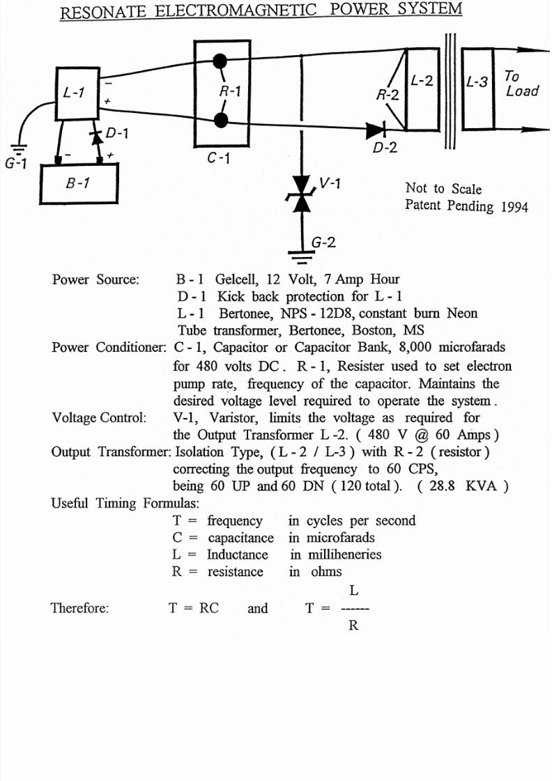
RESONATE ELECTROMAGNETIC POWER SYSTEM
8-1
Power Source:
Voltage Control:
Therefore:
To
LoL-2 L-3
C-1
T = RC and
B-1 Gelcell, 12 Volt, 7 Amp Hour
D - 1 Kick back protection for L- 1
L - 1 Bertonee,NPS - 12D8, constant burn Neon
Tube transformer, Bertonee, Boston, MS
Power Conditioner: C - 1, Capacitor or Capacitor Bank, 8,000 microfarads
for 480 volts DC. R- 1, Resister used to set electron
pump rate, .frequency of the capacitor. Maintains the
desired voltage level required to operate the system.V-I, Varistor, limits the voltage as required for
the Output Transfomier L -2. ( 480 V @ 60 Amps )
Output Transformer: Isolation Type, (L - 2 I L-3·) with R - 2 (resistor)
correcting the output frequency to 60 CPS,
being 60 UP and 60 DN ( 120 total). (28.8 KVA)
Useful Timing Formulas:
T = frequency
C capacitanceL = Inductance
R = resistance
D-2
V-1 Not to Scale
Patent Pending 199
in cycles per second
in microfaradsin milliheneries
in ohms
L
T=
R

5/17/2018 Dsmith Reference%231 - slidepdf.com
http://slidepdf.com/reader/full/dsmith-reference231 10/14
Comments
The information here given reflects the small Suitcase Model demonstrated
the Tesla Convention (1996), presented on VCR as Don Smith's Worksho
This unit was a very primitive version. Newer versions have atomic batteri
and Power Output ranges into the Giga Watts. The battery requirement is
low level and is no more harmful than the radium on the dial of a clock.Commercial Units ( Boulder Dam Size) are currently being installed at
Several Major Locations throughout the World. For reasons of Personal
Security and Contract Obligations the information herein given is incomplete

5/17/2018 Dsmith Reference%231 - slidepdf.com
http://slidepdf.com/reader/full/dsmith-reference231 11/14
Booker, H.G., " Energy in Electromagnetism", Institute of Electrical Enginee
Peter Peregrinus, Ltd., 1982, I.S.B.N. 0-906048-59-1
Bleany and Bleany, "Electricity and Magnetism", Oxford University Press
1991, I.S.B.N. 0-19-851172-8
Chapman and Bartels, "Geomagnetism", 3 vol., Oxford University Press,
1940
Hammond,P., "Energy Methods in Electromagnetism", Oxford University
Press, 1986, I.S.B.N. 0-19-859368-6
Matsushita and Campbell, "Physics of Geomagneic Phenomena", several
vols., National Center for Atmospheric Research, Boulder,Colorado, Academic press, 1967
Nashida, A, "Geomagnetic Diagnosis of the Magnetosphere ", University
of Tokyo, Springer-Verlag, 1978, IS.B.N. 0-387-08297-2
Rieger, Von Heinz., "Der Magnetisch Kreis It, Siemens A.G., Berlin and
Munchen, Germany, I.S.B.N. 3-8009-4719-6
Rokityansky, 1.1., "Geoelectrical investigation of the Earth's Crust and
Mantel ", Institute of Geophysics, Kiev, U.S.S.R., Springer-
Verlag, 1982, LS.B.N. 3-540-10630-8
Vigoureux, P., "Units and Standards for Electromagnetics", National
Physical Laboratory, 1971, Springer-Verlag,LS.B.N. 0-387-91077-8

5/17/2018 Dsmith Reference%231 - slidepdf.com
http://slidepdf.com/reader/full/dsmith-reference231 12/14
Finnell, Woosley, "Solar Power Satellite Microwave Transmission and
Receiver System. EnergyConversion Conference, Sept. 1981
pp 266-271
Glaser, " Satellite Solar Power Station" The Journal of Solar Energy
and Technology, Vol. 12, No.3., p. 353 .
Denmum et al, "A Microwave Power Transmission System for Space
Satellite Power", Energy Conversion Conference Conference,
Sept. 1977, pp 162-168
Nalos et al, "Microwave Power Beaming for long range energy transfer"
"Proceedings of the 8 th European Microwave Conference"
pp 573-578, 4 through 8 tho Sept., 1978
Angrist, S.W., "Direct Energy Conversion ", forth edition, Carnegie-Mellon
. University, Pub. Allyn and Bacon, Boston, London, Sidney an
Toronto, ISBN 0-205-07758-7
Smith, D.L., "An Answer to Americas Energy Delict" , fifth edition,
Pub. International Tesla Society, Colorado Springs, Co., 199
Aspden, H. "The Law of Electrodynamics", J. Franklin Inst., 287:179,
1969.
Sethian, J.D., "Anomalous Electron-Ion Energy Transfer ", Phys. Rev. Lett
vol. 40, No.7, pp. 451-454, 1978..
Westinghouse R. & D., "Electromagnetic Spectrum Chart"., Pub. The
Exploratorium, San Francisco,CA 94123, Distributed by
Edmond Scientific, Barrington, N.J. 06007
Order # 609-573-6250

5/17/2018 Dsmith Reference%231 - slidepdf.com
http://slidepdf.com/reader/full/dsmith-reference231 13/14
1
ELECTRICAL ENERG
Patent Pe
AC6A
\6
7
AC
1. Gelcel, 6 or 12 Volt.
2. Diode, POSSe use a Voractor.
3. High Voltage Module, Constituting the L-1 and L-2 Co
4. Capacitor, TDK 10.9 Pf., 30 KV.
5. Spark Gap, Small Engine Spark Plug, Gap = .0025 in.
6. Induction Transfer Coil L-3., 6A = L-5
7. Induction Receiving Coil L-4.8. Voltage Control Shunt.
9. Frequency Adjustor. prevents derating by Diode Bridg

5/17/2018 Dsmith Reference%231 - slidepdf.com
http://slidepdf.com/reader/full/dsmith-reference231 14/14
~GY ,GENERATING S Y S T E M
'endlnq 08/100,074
15
~c+
~C
14 -00
16
10. Diode Bridge, 200 Nanosecond. R.F.,> 100KV.
11. Voltage Divider Circuit, corrects voltage for next stage.
;oils. 12. Capacitor, elecrrolync, smooths out DC + ripple effect.
13. Earth Ground.
14. Voltage Divider Curcit, corrects voltage for Transformer
15. Inverter Circuit, DC + in and 60 CPS to Transformer
16. Output from Transformer to Load (Work).
jQe20 Dec .• 1994