dspic33e/pic24e frm section 15. quadrature …ww1.microchip.com/downloads/en/devicedoc/s15.pdftable...
TRANSCRIPT
Section 15. Quadrature Encoder Interface (QEI)
Quadrature Encoder
Interface (QEI)
15
HIGHLIGHTSThis section of the manual contains the following major topics:
15.1 Introduction .................................................................................................................. 15-215.2 Control and Status Registers ....................................................................................... 15-515.3 Module Description .................................................................................................... 15-2115.4 QEI Operation in Power-Saving Modes ..................................................................... 15-2915.5 Effects of a Reset....................................................................................................... 15-2915.6 Register Map.............................................................................................................. 15-3015.7 Design Tips ................................................................................................................ 15-3115.8 Related Application Notes.......................................................................................... 15-3215.9 Revision History ......................................................................................................... 15-33
© 2010 Microchip Technology Inc. DS70601B-page 15-1

dsPIC33E/PIC24E Family Reference Manual
15.1 INTRODUCTIONThe Quadrature Encoder Interface (QEI) module provides the interface to incremental encodersfor obtaining mechanical position data. Quadrature encoders, also known as incrementalencoders or optical encoders, detect position and speed of rotating motion systems. Quadratureencoders enable closed-loop control of motor control applications, such as Switched Reluctance(SR) and AC Induction Motors (ACIM).
A typical quadrature encoder includes a slotted wheel attached to the shaft of the motor and anEmitter/Detector module that senses the slots in the wheel. Typically, three output channels,Phase A (QEA), Phase B (QEB) and Index (INDX) provide information on the movement of themotor shaft, including distance and direction.
The two channels, Phase A (QEA) and Phase B (QEB), are typically 90º out of phase withrespect to each other. The Phase A and Phase B channels have a unique relationship. If PhaseA leads Phase B, the direction of the motor is deemed positive or forward. If Phase A lagsPhase B, the direction of the motor is deemed negative or reverse. The Index pulse occurs onceper mechanical revolution and is used as a reference to indicate an absolute position.Figure 15-1 illustrates the quadrature encoder interface signals.
The quadrature signals from the encoder can have four unique states (01, 00, 10 and 11) thatreflect the relationship between QEA and QEB. Figure 15-1 illustrates these states for one countcycle. The order of the states get reversed when the direction of travel changes.
The quadrature decoder increments or decrements the 32-bit Up/Down Position Counter(POSCNT) for each change of state. The counter increments when QEA leads QEB anddecrements when QEB leads QEA.
Figure 15-1: Quadrature Encoder Interface Signals
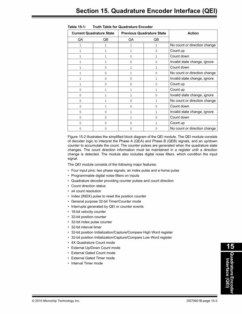
Table 15-1 shows the truth table that describes how the quadrature signals are decoded.
Note: This family reference manual section is meant to serve as a complement to devicedata sheets. Depending on the device variant, this manual section may not applyto all dsPIC33E/PIC24E devices.
Please consult the note at the beginning of the “Quadrature Encoder Interface(QEI)” chapter in the current device data sheet to check whether this documentsupports the device you are using.
Device data sheets and family reference manual sections are available fordownload from the Microchip Worldwide Web site at: http://www.microchip.com
+1+1 +1 +1 +1 +1 +1 +1 +1 +1 +1 +1 +1 +1 +1 -1 -1 -1 -1 -1 -1 -1 -1 -1 -1 -1 -1 -1 -1 -1POSCNT
UP/DOWN
QEA
QEB
-1
DS70601B-page 15-2 © 2010 Microchip Technology Inc.
Section 15. Quadrature Encoder Interface (QEI)Q
uadrature EncoderInterface (Q
EI)
15
Figure 15-2 illustrates the simplified block diagram of the QEI module. The QEI module consistsof decoder logic to interpret the Phase A (QEA) and Phase B (QEB) signals, and an up/downcounter to accumulate the count. The counter pulses are generated when the quadrature statechanges. The count direction information must be maintained in a register until a directionchange is detected. The module also includes digital noise filters, which condition the inputsignal.
The QEI module consists of the following major features:
• Four input pins: two phase signals, an index pulse and a home pulse• Programmable digital noise filters on inputs• Quadrature decoder providing counter pulses and count direction• Count direction status• x4 count resolution• Index (INDX) pulse to reset the position counter• General purpose 32-bit Timer/Counter mode• Interrupts generated by QEI or counter events• 16-bit velocity counter• 32-bit position counter• 32-bit index pulse counter• 32-bit interval timer• 32-bit position Initialization/Capture/Compare High Word register• 32-bit position Initialization/Capture/Compare Low Word register• 4X Quadrature Count mode• External Up/Down Count mode• External Gated Count mode• External Gated Timer mode• Interval Timer mode
Table 15-1: Truth Table for Quadrature Encoder
Current Quadrature State Previous Quadrature State Action
QA QB QA QB1 1 1 1 No count or direction change1 1 1 0 Count up1 1 0 1 Count down 1 1 0 0 Invalid state change, ignore1 0 1 1 Count down1 0 1 0 No count or direction change1 0 0 1 Invalid state change, ignore1 0 0 0 Count up0 1 1 1 Count up0 1 1 0 Invalid state change, ignore0 1 0 1 No count or direction change0 1 0 0 Count down0 0 1 1 Invalid state change, ignore0 0 1 0 Count down0 0 0 1 Count up0 0 0 0 No count or direction change
© 2010 Microchip Technology Inc. DS70601B-page 15-3

dsPIC33E/PIC
24E Family R
eference Manual
DS
70601B-page 15-4
© 2010 M
icrochip Technology Inc.
COUNT_EN
32-bit Greater Than or EqualCompare Register
32-bit Greater Than
Data Bus
PCHEQ
PCHGE
CNT_DIR
GATEN
0
1
or Equal Comparator
(QEIxGEC)(1)
32-bit Initialization and Capture Register
(QEIxIC)(1)
APEN
ter
Figure 15-2: Quadrature Encoder Interface (QEI) Module Block Diagram
QuadratureDecoder
Logic
CNTCMPx
QEBx
QEAx
INDXx
COUNT
DIR
FCY COUNT
32-bit Index Counter Register
DigitalFilter
HOMEx FHOMEx
Data Bus
COUNT_EN
CNT_DIRCNT_DIR
FINDXx
FINDXx
32-bit Interval Timer16-bit Index Counter Hold Register
32-bit IntervalTimer Register
Hold Register
COUNT_EN
FCY
EXTCNT
EXTCNT
DIR_GATE
16-bit Velocity
COUNT_ENCNT_DIR
Counter Register
PCLLEPCHGE
DIVCLK
DIRDIR_GATE
1’B0
PCLLE
CNTPOL
DIR_GATE
DIVCLK
32-bit Less Than
PCLLEor Equal Comparator
PCLEQPCHGE
÷ QFDIV
CCM
÷ INTDIV
(VELxCNT)
(INTxTMR)
(INTxHLD)
(INDXxCNT)
(INDXxHLD)
INDXxCNTLINDXxCNTHPOSxCNTLPOSxCNTH
32-bit Less Than or EqualCompare Register
(QEIxLEC)
16-bit Position CounterHold Register(POSxHLD)
QC
32-bit Position Counter Regis(POSxCNT)
Note 1: These registers map to the same memory location.
OUTFNC
FLTREN

Section 15. Quadrature Encoder Interface (QEI)Q
uadrature EncoderInterface (Q
EI)
15
15.2 CONTROL AND STATUS REGISTERSThe following registers are associated with the QEI module:
• QEIxCON: QEI Control RegisterThis register controls the QEI module operation.
• QEIxIOC: QEI I/O Control Register This register controls the input/output mode of the QEI module.
• QEIxSTAT: QEI Status Register This register provides the interrupt enable flag and status flag to indicate the status of the QEImodule.
• POSxCNTH: Position Counter High Word Register This register is the high word of the position counter.
• POSxCNTL: Position Counter Low Word RegisterThis register is the low word of the position counter.
• POSxHLD: Position Counter Hold Register This register holds the contents of the POSxCNTH register during the read or write operation.
• VELxCNT: Velocity Counter Register This register stores the velocity value.
• INDXxCNTH: Index Counter High Word Register This register is the high word of the index counter.
• INDXxCNTL: Index Counter Low Word Register This register is the low word of the index counter.
• INDXxHLD: Index Counter Hold Register This register holds the contents of the INDXxCNTH register during the read or write operation.
• QEIxICH: Initialization/Capture High Word Register This register is the high word of the QEIxIC register.
• QEIxICL: Initialization/Capture Low Word Register This register is the low word of the QEIxIC register.
• QEIxLECH: Less Than or Equal Compare High Word Register This register is the high word 16-bit less than or equal compare register.
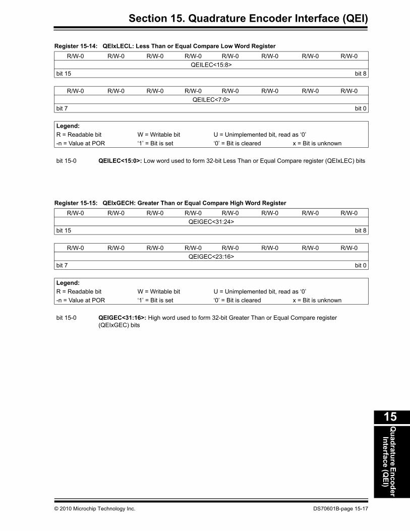
• QEIxLECL: Less Than or Equal Compare Low Word RegisterThis register is the low word 16-bit less than or equal compare register.
• QEIxGECH: Greater Than or Equal Compare High Word RegisterThis register is the high word 16-bit greater than or equal compare register.
• QEIxGECL: Greater Than or Equal Compare Low Word Register This register is the low word 16-bit greater than or equal compare register.
• INTxTMRH: Interval Timer High Word Register This register is the high word of the Counter Pulse Interval Timer register.
• INTxTMRL: Interval Timer Low Word Register This register is the low word of the Counter Pulse Interval Timer register.
• INTxHLDH: Interval Timer Hold High Word Register This register holds the content of high word of the Interval Timer Hold register.
• INTxHLDL: Interval Timer Hold Low Word Register This register holds the content of low word of the Interval Timer Hold register.
© 2010 Microchip Technology Inc. DS70601B-page 15-5

dsPIC33E/PIC24E Family Reference Manual
Register 15-1: QEIxCON: QEI Control Register
R/W-0 U-0 R/W-0 R/W-0 R/W-0 R/W-0 R/W-0 R/W-0QEIEN — QEISIDL PIMOD<2:0>(1) IMV<1:0>(2)
bit 15 bit 8
U-0 R/W-0 R/W-0 R/W-0 R/W-0 R/W-0 R/W-0 R/W-0— INTDIV<2:0>(3) CNTPOL GATEN CCM<1:0>
bit 7 bit 0
Legend:R = Readable bit W = Writable bit U = Unimplemented bit, read as ‘0’-n = Value at POR ‘1’ = Bit is set ‘0’ = Bit is cleared x = Bit is unknown
bit 15 QEIEN: Quadrature Encoder Interface Module Counter Enable bit1 = Module counters are enabled0 = Module counters are disabled, but SFRs can be read or written
bit 14 Unimplemented: Read as ‘0’bit 13 QEISIDL: Stop in Idle Mode bit
1 = Discontinue module operation when device enters Idle mode0 = Continue module operation in Idle mode
bit 12-10 PIMOD<2:0>: Position Counter Initialization Mode Select bits(1)
111 = Reserved110 = Modulo Count mode for position counter101 = Resets the position counter when the position counter equals QEIxGEC register 100 = Second index event after home event initializes position counter with contents of QEIxIC
register011 = First index event after home event initializes position counter with contents of QEIxIC register010 = Next index input event initializes the position counter with contents of QEIxIC register001 = Every Index input event resets the position counter000 = Index input event does not affect position counter
bit 9-8 IMV<1:0>: Index Match Value bits(2) 11 = Index match occurs when QEB = 1 and QEA = 1 10 = Index match occurs when QEB = 1 and QEA = 0 01 = Index match occurs when QEB = 0 and QEA = 1 00 = Index input event does not affect position counter
bit 7 Unimplemented: Read as ‘0’bit 6-4 INTDIV<2:0>: Timer Input Clock Prescale Select bits (Interval timer, Main timer (position counter),
velocity counter and index counter internal clock divider select)(3)
111 = 1:256 prescale value110 = 1:64 prescale value101 = 1:32 prescale value100 = 1:16 prescale value011 = 1:8 prescale value010 = 1:4 prescale value001 = 1:2 prescale value000 = 1:1 prescale value
Note 1: When CCM = 10 or CCM = 11, all of the QEI counters operate as timers and the PIMOD<2:0> bits areignored.
2: When CCM = 00 and QEA and QEB values match Index Match Value (IMV), the POSxCNTH andPOSxCNTL registers are reset.
3: The selected clock rate should be at least twice the expected maximum quadrature count rate.
DS70601B-page 15-6 © 2010 Microchip Technology Inc.

Section 15. Quadrature Encoder Interface (QEI)Q
uadrature EncoderInterface (Q
EI)
15
bit 3 CNTPOL: Position and Index Counter/Timer Direction Select bit1 = Counter direction is negative unless modified by external Up/Down signal0 = Counter direction is positive unless modified by external Up/Down signal
bit 2 GATEN: External Count Gate Enable bit1 = External gate signal controls position counter operation0 = External gate signal does not affect position counter/timer operation
bit 1-0 CCM<1:0>: Counter Control Mode Selection bits11 = Internal Timer mode10 = External clock count with external Gate mode01 = External clock count with external Up/Down mode00 = Quadrature Encoder mode
Register 15-1: QEIxCON: QEI Control Register (Continued)
Note 1: When CCM = 10 or CCM = 11, all of the QEI counters operate as timers and the PIMOD<2:0> bits areignored.
2: When CCM = 00 and QEA and QEB values match Index Match Value (IMV), the POSxCNTH andPOSxCNTL registers are reset.
3: The selected clock rate should be at least twice the expected maximum quadrature count rate.
© 2010 Microchip Technology Inc. DS70601B-page 15-7

dsPIC33E/PIC24E Family Reference Manual
Register 15-2: QEIxIOC: QEI I/O Control Register
R/W-0 R/W-0 R/W-0 R/W-0 R/W-0 R/W-0 R/W-0 R/W-0QCAPEN FLTREN QFDIV<2:0> OUTFNC<1:0> SWPAB
bit 15 bit 8
R/W-0 R/W-0 R/W-0 R/W-0 R-x R-x R-x R-xHOMPOL IDXPOL QEBPOL QEAPOL HOME INDEX QEB QEA
bit 7 bit 0
Legend:R = Readable bit W = Writable bit U = Unimplemented bit, read as ‘0’-n = Value at POR ‘1’ = Bit is set ‘0’ = Bit is cleared x = Bit is unknown
bit 15 QCAPEN: Position Counter Input Capture Enable bit 1 = HOMEx input event (positive edge) triggers a position capture event0 = HOMEx input event (positive edge) does not trigger a position capture event
bit 14 FLTREN: QEA/QEB/INDX/HOMEx Digital Filter Enable bit1 = Input Pin Digital filter is enabled0 = Input Pin Digital filter is disabled (bypassed)
bit 13-11 QFDIV<2:0>: QEA/QEB/INDX/HOMEx Digital Input Filter Clock Divide Select bits111 = 1:256 clock divide110 = 1:64 clock divide101 = 1:32 clock divide100 = 1:16 clock divide011 = 1:8 clock divide010 = 1:4 clock divide001 = 1:2 clock divide000 = 1:1 clock divide
bit 10-9 OUTFNC<1:0>: QEI Module Output Function Mode Select bits11 = The CNTCMPx pin goes high when POSxCNT ≤ QEIxLEC or POSxCNT ≥ QEIxGEC10 = The CNTCMPx pin goes high when POSxCNT ≤ QEIxLEC01 = The CNTCMPx pin goes high when POSxCNT ≥ QEIxGEC00 = Output is disabled
bit 8 SWPAB: Swap QEA and QEB Inputs bit1 = QEAx and QEBx are swapped prior to quadrature decoder logic0 = QEAx and QEBx are not swapped
bit 7 HOMPOL: HOMEx Input Polarity Select bit1 = Input is inverted0 = Input is not inverted
bit 6 IDXPOL: INDXx Input Polarity Select bit1 = Input is inverted0 = Input is not inverted
bit 5 QEBPOL: QEBx Input Polarity Select bit1 = Input is inverted0 = Input is not inverted
bit 4 QEAPOL: QEAx Input Polarity Select bit1 = Input is inverted0 = Input is not inverted
DS70601B-page 15-8 © 2010 Microchip Technology Inc.

Section 15. Quadrature Encoder Interface (QEI)Q
uadrature EncoderInterface (Q
EI)
15
bit 3 HOME: Status of HOMEx Input Pin after Polarity Control bit (read-only)1 = Pin is at logic ‘1’, if HOMPOL bit is set to ‘0’
Pin is at logic ‘0’, if HOMPOL bit is set to ‘1’0 = Pin is at logic ‘0’, if HOMPOL bit is set to ‘0’
Pin is at logic ‘1’, if HOMPOL bit is set to ‘1’bit 2 INDEX: Status of INDXx Input Pin after Polarity Control bit (Read-Only)
1 = Pin is at logic ‘1’, if IDXPOL bit is set to ‘0’Pin is at logic ‘0’, if IDXPOL bit is set to ‘1’
0 = Pin is at logic ‘0’, if IDXPOL bit is set to ‘0’Pin is at logic ‘1’, if IDXPOL bit is set to ‘1’
bit 1 QEB: Status of QEBx Input Pin after Polarity Control and SWPAB Pin Swapping bit (read-only)1 = Physical pin QEB is at logic ‘1’, if QEBPOL bit is set to ‘0’ and SWPAB bit is set to ‘0’
Physical pin QEB is at logic ‘0’, if QEBPOL bit is set to ‘1’ and SWPAB bit is set to ‘0’Physical pin QEA is at logic ‘1’, if QEBPOL bit is set to ‘0’ and SWPAB bit is set to ‘1’Physical pin QEA is at logic ‘0’, if QEBPOL bit is set to ‘1’ and SWPAB bit is set to ‘1’
0 = Physical pin QEB is at logic ‘0’, if QEBPOL bit is set to ‘0’ and SWPAB bit is set to ‘0’Physical pin QEB is at logic ‘1’, if QEBPOL bit is set to ‘1’ and SWPAB bit is set to ‘0’Physical pin QEA is at logic ‘0’, if QEBPOL bit is set to ‘0’ and SWPAB bit is set to ‘1’Physical pin QEA is at logic ‘1’, if QEBPOL bit is set to ‘1’ and SWPAB bit is set to ‘1’
bit 0 QEA: Status of QEAx Input Pin after Polarity Control and SWPAB Pin Swapping bit (read-only)1 = Physical pin QEA is at logic ‘1’, if QEAPOL bit is set to ‘0’ and SWPAB bit is set to ‘0’
Physical pin QEA is at logic ‘0’, if QEAPOL bit is set to ‘1’ and SWPAB bit is set to ‘0’Physical pin QEB is at logic ‘1’, if QEAPOL bit is set to ‘0’ and SWPAB bit is set to ‘1’Physical pin QEB is at logic ‘0’, if QEAPOL bit is set to ‘1’ and SWPAB bit is set to ‘1’
0 = Physical pin QEA is at logic ‘0’, if QEAPOL bit is set to ‘0’ and SWPAB bit is set to ‘0’Physical pin QEA is at logic ‘1’, if QEAPOL bit is set to ‘1’ and SWPAB bit is set to ‘0’Physical pin QEB is at logic ‘0’, if QEAPOL bit is set to ‘0’ and SWPAB bit is set to ‘1’Physical pin QEB is at logic ‘1’, if QEAPOL bit is set to ‘1’ and SWPAB bit is set to ‘1’
Register 15-2: QEIxIOC: QEI I/O Control Register (Continued)
© 2010 Microchip Technology Inc. DS70601B-page 15-9

dsPIC33E/PIC24E Family Reference Manual
Register 15-3: QEIxSTAT: QEI Status Register
U-0 U-0 HS, R/C-0 R/W-0 HS, R/C-0 R/W-0 HS, R/C-0 R/W-0— — PCHEQIRQ PCHEQIEN PCLEQIRQ PCLEQIEN POSOVIRQ POSOVIEN
bit 15 bit 8
HS, R/C-0 R/W-0 HS, R/C-0 R/W-0 HS, R/C-0 R/W-0 HS, R/C-0 R/W-0PCIIRQ(1) PCIIEN VELOVIRQ VELOVIEN HOMIRQ HOMIEN IDXIRQ IDXIENbit 7 bit 0
Legend: C = Clearable bit HS = Set in HardwareR = Readable bit W = Writable bit U = Unimplemented bit, read as ‘0’-n = Value at POR ‘1’ = Bit is set ‘0’ = Bit is cleared x = Bit is unknown
bit 15-14 Unimplemented: Read as ‘0’bit 13 PCHEQIRQ: Position Counter Greater Than or Equal Compare Status bit
1 = POSxCNT ≥ QEIxGEC0 = POSxCNT < QEIxGEC
bit 12 PCHEQIEN: Position Counter Greater Than or Equal Compare Interrupt Enable bit1 = Interrupt is enabled0 = Interrupt is disabled
bit 11 PCLEQIRQ: Position Counter Less Than or Equal Compare Status bit1 = POSxCNT ≤ QEIxLEC0 = POSxCNT > QEIxLEC
bit 10 PCLEQIEN: Position Counter Less Than or Equal Compare Interrupt Enable bit1 = Interrupt is enabled0 = Interrupt is disabled
bit 9 POSOVIRQ: Position Counter Overflow Status bit1 = Overflow has occurred0 = No overflow has occurred
bit 8 POSOVIEN: Position Counter Overflow Interrupt Enable bit1 = Interrupt is enabled0 = Interrupt is disabled
bit 7 PCIIRQ: Position Counter (Homing) Initialization Process Complete Status bit(1)
1 = POSxCNT was reinitialized0 = POSxCNT was not reinitialized
bit 6 PCIIEN: Position Counter (Homing) Initialization Process Complete Interrupt Enable bit1 = Interrupt is enabled0 = Interrupt is disabled
bit 5 VELOVIRQ: Velocity Counter Overflow Status bit1 = Overflow has occurred0 = No overflow has occurred
bit 4 VELOVIEN: Velocity Counter Overflow Interrupt Enable bit1 = Interrupt is enabled0 = Interrupt is disabled
bit 3 HOMIRQ: Status Flag for Home Event Status bit1 = Home event has occurred0 = No Home event has occurred
Note 1: This status bit is only applicable to PIMOD<2:0> modes ‘011’ and ‘100’.
DS70601B-page 15-10 © 2010 Microchip Technology Inc.

Section 15. Quadrature Encoder Interface (QEI)Q
uadrature EncoderInterface (Q
EI)
15
bit 2 HOMIEN: Home Input Event Interrupt Enable bit1 = Interrupt is enabled0 = Interrupt is disabled
bit 1 IDXIRQ: Status Flag for Index Event Status bit1 = Index event has occurred0 = No Index event has occurred
bit 0 IDXIEN: Index Input Event Interrupt Enable bit1 = Interrupt is enabled0 = Interrupt is disabled
Register 15-3: QEIxSTAT: QEI Status Register (Continued)
Note 1: This status bit is only applicable to PIMOD<2:0> modes ‘011’ and ‘100’.
© 2010 Microchip Technology Inc. DS70601B-page 15-11

dsPIC33E/PIC24E Family Reference Manual
Register 15-4: POSxCNTH: Position Counter High Word RegisterR/W-0 R/W-0 R/W-0 R/W-0 R/W-0 R/W-0 R/W-0 R/W-0
POSCNT<31:24>bit 15 bit 8
R/W-0 R/W-0 R/W-0 R/W-0 R/W-0 R/W-0 R/W-0 R/W-0POSCNT<23:16>
bit 7 bit 0
Legend:R = Readable bit W = Writable bit U = Unimplemented bit, read as ‘0’-n = Value at POR ‘1’ = Bit is set ‘0’ = Bit is cleared x = Bit is unknown
bit 15-0 POSCNT<31:16>: High word used to form 32-bit Position Counter register (POSxCNT) bits
Register 15-5: POSxCNTL: Position Counter Low Word RegisterR/W-0 R/W-0 R/W-0 R/W-0 R/W-0 R/W-0 R/W-0 R/W-0
POSCNT<15:8>bit 15 bit 8
R/W-0 R/W-0 R/W-0 R/W-0 R/W-0 R/W-0 R/W-0 R/W-0POSCNT<7:0>
bit 7 bit 0
Legend:R = Readable bit W = Writable bit U = Unimplemented bit, read as ‘0’-n = Value at POR ‘1’ = Bit is set ‘0’ = Bit is cleared x = Bit is unknown
bit 15-0 POSCNT<15:0>: Low word used to form 32-bit Position Counter register (POSxCNT) bits
DS70601B-page 15-12 © 2010 Microchip Technology Inc.

Section 15. Quadrature Encoder Interface (QEI)Q
uadrature EncoderInterface (Q
EI)
15
Register 15-6: POSxHLD: Position Counter Hold RegisterR/W-0 R/W-0 R/W-0 R/W-0 R/W-0 R/W-0 R/W-0 R/W-0
POSHLD<15:8>bit 15 bit 8
R/W-0 R/W-0 R/W-0 R/W-0 R/W-0 R/W-0 R/W-0 R/W-0POSHLD<7:0>
bit 7 bit 0
Legend:R = Readable bit W = Writable bit U = Unimplemented bit, read as ‘0’-n = Value at POR ‘1’ = Bit is set ‘0’ = Bit is cleared x = Bit is unknown
bit 15-0 POSHLD<15:0>: Hold register bits for reading and writing Position Counter High Word register(POSxCNTH) bits
Register 15-7: VELxCNT: Velocity Counter Register R/W-0 R/W-0 R/W-0 R/W-0 R/W-0 R/W-0 R/W-0 R/W-0
VELCNT<15:8>bit 15 bit 8
R/W-0 R/W-0 R/W-0 R/W-0 R/W-0 R/W-0 R/W-0 R/W-0VELCNT<7:0>
bit 7 bit 0
Legend:R = Readable bit W = Writable bit U = Unimplemented bit, read as ‘0’-n = Value at POR ‘1’ = Bit is set ‘0’ = Bit is cleared x = Bit is unknown
bit 15-0 VELCNT<15:0>: Velocity Counter bits
© 2010 Microchip Technology Inc. DS70601B-page 15-13

dsPIC33E/PIC24E Family Reference Manual
Register 15-8: INDXxCNTH: Index Counter High Word RegisterR/W-0 R/W-0 R/W-0 R/W-0 R/W-0 R/W-0 R/W-0 R/W-0
INDXCNT<31:24>bit 15 bit 8
R/W-0 R/W-0 R/W-0 R/W-0 R/W-0 R/W-0 R/W-0 R/W-0INDXCNT<23:16>
bit 7 bit 0
Legend:R = Readable bit W = Writable bit U = Unimplemented bit, read as ‘0’-n = Value at POR ‘1’ = Bit is set ‘0’ = Bit is cleared x = Bit is unknown
bit 15-0 INDXCNT<31:16>: High word used to form 32-bit Index Counter register (INDXxCNT) bits
Register 15-9: INDXxCNTL: Index Counter Low Word RegisterR/W-0 R/W-0 R/W-0 R/W-0 R/W-0 R/W-0 R/W-0 R/W-0
INDXCNT<15:8>bit 15 bit 8
R/W-0 R/W-0 R/W-0 R/W-0 R/W-0 R/W-0 R/W-0 R/W-0INDXCNT<7:0>
bit 7 bit 0
Legend:R = Readable bit W = Writable bit U = Unimplemented bit, read as ‘0’-n = Value at POR ‘1’ = Bit is set ‘0’ = Bit is cleared x = Bit is unknown
bit 15-0 INDXCNT<15:0>: Low word used to form 32-bit Index Counter register (INDXxCNT) bits
DS70601B-page 15-14 © 2010 Microchip Technology Inc.

Section 15. Quadrature Encoder Interface (QEI)Q
uadrature EncoderInterface (Q
EI)
15
Register 15-10: INDXxHLD: Index Counter Hold RegisterR/W-0 R/W-0 R/W-0 R/W-0 R/W-0 R/W-0 R/W-0 R/W-0
INDXHLD<15:8>bit 15 bit 8
R/W-0 R/W-0 R/W-0 R/W-0 R/W-0 R/W-0 R/W-0 R/W-0INDXHLD<7:0>
bit 7 bit 0
Legend:R = Readable bit W = Writable bit U = Unimplemented bit, read as ‘0’-n = Value at POR ‘1’ = Bit is set ‘0’ = Bit is cleared x = Bit is unknown
bit 15-0 INDXHLD<15:0>: Hold register for reading and writing Index Counter High Word register (INDXxCNTH) bits
Register 15-11: QEIxICH: Initialization/Capture High Word RegisterR/W-0 R/W-0 R/W-0 R/W-0 R/W-0 R/W-0 R/W-0 R/W-0
QEIIC<31:24>bit 15 bit 8
R/W-0 R/W-0 R/W-0 R/W-0 R/W-0 R/W-0 R/W-0 R/W-0QEIIC<23:16>
bit 7 bit 0
Legend:R = Readable bit W = Writable bit U = Unimplemented bit, read as ‘0’-n = Value at POR ‘1’ = Bit is set ‘0’ = Bit is cleared x = Bit is unknown
bit 15-0 QEIIC<31:16>: High word used to form 32-bit Initialization/Capture register (QEIxIC) bits
© 2010 Microchip Technology Inc. DS70601B-page 15-15

dsPIC33E/PIC24E Family Reference Manual
Register 15-12: QEIxICL: Initialization/Capture Low Word RegisterR/W-0 R/W-0 R/W-0 R/W-0 R/W-0 R/W-0 R/W-0 R/W-0
QEIIC<15:8>bit 15 bit 8
R/W-0 R/W-0 R/W-0 R/W-0 R/W-0 R/W-0 R/W-0 R/W-0QEIIC<7:0>
bit 7 bit 0
Legend:R = Readable bit W = Writable bit U = Unimplemented bit, read as ‘0’-n = Value at POR ‘1’ = Bit is set ‘0’ = Bit is cleared x = Bit is unknown
bit 15-0 QEIIC<15:0>: Low word used to form 32-bit Initialization/Capture register (QEIxIC) bits
Register 15-13: QEIxLECH: Less Than or Equal Compare High Word RegisterR/W-0 R/W-0 R/W-0 R/W-0 R/W-0 R/W-0 R/W-0 R/W-0
QEILEC<31:24>bit 15 bit 8
R/W-0 R/W-0 R/W-0 R/W-0 R/W-0 R/W-0 R/W-0 R/W-0QEILEC<23:16>
bit 7 bit 0
Legend:R = Readable bit W = Writable bit U = Unimplemented bit, read as ‘0’-n = Value at POR ‘1’ = Bit is set ‘0’ = Bit is cleared x = Bit is unknown
bit 15-0 QEILEC<31:16>: High word used to form 32-bit Less Than or Equal Compare register (QEIxLEC) bits
DS70601B-page 15-16 © 2010 Microchip Technology Inc.
Section 15. Quadrature Encoder Interface (QEI)Q
uadrature EncoderInterface (Q
EI)
15
Register 15-14: QEIxLECL: Less Than or Equal Compare Low Word RegisterR/W-0 R/W-0 R/W-0 R/W-0 R/W-0 R/W-0 R/W-0 R/W-0
QEILEC<15:8>bit 15 bit 8
R/W-0 R/W-0 R/W-0 R/W-0 R/W-0 R/W-0 R/W-0 R/W-0QEILEC<7:0>
bit 7 bit 0
Legend:R = Readable bit W = Writable bit U = Unimplemented bit, read as ‘0’-n = Value at POR ‘1’ = Bit is set ‘0’ = Bit is cleared x = Bit is unknown
bit 15-0 QEILEC<15:0>: Low word used to form 32-bit Less Than or Equal Compare register (QEIxLEC) bits
Register 15-15: QEIxGECH: Greater Than or Equal Compare High Word RegisterR/W-0 R/W-0 R/W-0 R/W-0 R/W-0 R/W-0 R/W-0 R/W-0
QEIGEC<31:24>bit 15 bit 8
R/W-0 R/W-0 R/W-0 R/W-0 R/W-0 R/W-0 R/W-0 R/W-0QEIGEC<23:16>
bit 7 bit 0
Legend:R = Readable bit W = Writable bit U = Unimplemented bit, read as ‘0’-n = Value at POR ‘1’ = Bit is set ‘0’ = Bit is cleared x = Bit is unknown
bit 15-0 QEIGEC<31:16>: High word used to form 32-bit Greater Than or Equal Compare register (QEIxGEC) bits
© 2010 Microchip Technology Inc. DS70601B-page 15-17

dsPIC33E/PIC24E Family Reference Manual
Register 15-16: QEIxGECL: Greater Than or Equal Compare Low Word RegisterR/W-0 R/W-0 R/W-0 R/W-0 R/W-0 R/W-0 R/W-0 R/W-0
QEIGEC<15:8>bit 15 bit 8
R/W-0 R/W-0 R/W-0 R/W-0 R/W-0 R/W-0 R/W-0 R/W-0QEIGEC<7:0>
bit 7 bit 0
Legend:R = Readable bit W = Writable bit U = Unimplemented bit, read as ‘0’-n = Value at POR ‘1’ = Bit is set ‘0’ = Bit is cleared x = Bit is unknown
bit 15-0 QEIGEC<15:0>: Low word used to form 32-bit Greater Than or Equal Compare register (QEIxGEC) bits
Register 15-17: INTxTMRH: Interval Timer High Word Register
R/W-0 R/W-0 R/W-0 R/W-0 R/W-0 R/W-0 R/W-0 R/W-0INTTMR<31:24>
bit 15 bit 8
R/W-0 R/W-0 R/W-0 R/W-0 R/W-0 R/W-0 R/W-0 R/W-0INTTMR<23:16>
bit 7 bit 0
Legend:R = Readable bit W = Writable bit U = Unimplemented bit, read as ‘0’-n = Value at POR ‘1’ = Bit is set ‘0’ = Bit is cleared x = Bit is unknown
bit 15-0 INTTMR<31:16>: High word used to form 32-bit Interval Timer register (INTxTMR) bits
DS70601B-page 15-18 © 2010 Microchip Technology Inc.

Section 15. Quadrature Encoder Interface (QEI)Q
uadrature EncoderInterface (Q
EI)
15
Register 15-18: INTxTMRL: Interval Timer Low Word RegisterR/W-0 R/W-0 R/W-0 R/W-0 R/W-0 R/W-0 R/W-0 R/W-0
INTTMR<15:8>bit 15 bit 8
R/W-0 R/W-0 R/W-0 R/W-0 R/W-0 R/W-0 R/W-0 R/W-0INTTMR<7:0>
bit 7 bit 0
Legend:R = Readable bit W = Writable bit U = Unimplemented bit, read as ‘0’-n = Value at POR ‘1’ = Bit is set ‘0’ = Bit is cleared x = Bit is unknown
bit 15-0 INTTMR<15:0>: Low word used to form 32-bit Interval Timer register (INTxTMR) bits
Register 15-19: INTxHLDH: Interval Timer Hold High Word RegisterR/W-0 R/W-0 R/W-0 R/W-0 R/W-0 R/W-0 R/W-0 R/W-0
INTHLD<31:24>bit 15 bit 8
R/W-0 R/W-0 R/W-0 R/W-0 R/W-0 R/W-0 R/W-0 R/W-0INTHLD<23:16>
bit 7 bit 0
Legend:R = Readable bit W = Writable bit U = Unimplemented bit, read as ‘0’-n = Value at POR ‘1’ = Bit is set ‘0’ = Bit is cleared x = Bit is unknown
bit 15-0 INTHLD<31:16>: High word used to form 32-bit Interval Timer Hold register (INTxHLD) bits
© 2010 Microchip Technology Inc. DS70601B-page 15-19

dsPIC33E/PIC24E Family Reference Manual
Register 15-20: INTxHLDL: Interval Timer Hold Low Word RegisterR/W-0 R/W-0 R/W-0 R/W-0 R/W-0 R/W-0 R/W-0 R/W-0
INTHLD<15:8>bit 15 bit 8
R/W-0 R/W-0 R/W-0 R/W-0 R/W-0 R/W-0 R/W-0 R/W-0INTHLD<7:0>
bit 7 bit 0
Legend:R = Readable bit W = Writable bit U = Unimplemented bit, read as ‘0’-n = Value at POR ‘1’ = Bit is set ‘0’ = Bit is cleared x = Bit is unknown
bit 15-0 INTHLD<15:0>: Low word used to form 32-bit Interval Timer Hold register (INTxHLD) bits
DS70601B-page 15-20 © 2010 Microchip Technology Inc.

Section 15. Quadrature Encoder Interface (QEI)Q
uadrature EncoderInterface (Q
EI)
15
15.3 MODULE DESCRIPTION
15.3.1 Position CounterThe position counter is 32 bits wide and is contained in two separate 16-bit registers: POSxCNTLand POSxCNTH. The counter counts the number of pulses generated by an encoder.
To read the counter during the counter operation, the user application should first read the leastsignificant word (lsw) of the counter value from the POSxCNTL register. When the lsw is readfirst, the contents of POSxCNTH are automatically transferred into a hold register, POSxHLD.The user application can then read the POSxHLD register to get the most significant word (msw)of the counter value. The hold register (POSxHLD) ensures that the occurrence of a carry orborrow between the read operation does not affect the reading of a coherent 32-bit value.
To write a value to the POSxCNTL:POSxCNTH register pair, the user application should firstwrite the msw to the POSxHLD register. When the lsw of the timer value is written to thePOSxCNTL register, the contents of POSxHLD are automatically transferred to the POSxCNTHregister. Thus, a coherent 32-bit value can be loaded into the position counter in a single clockcycle.
If the POSOVIEN bit in the QEI Status register (QEIxSTAT<8>) is set, and the position counterrolls over from 0x7FFFFFFF to 0x80000000, or from 0x80000000 to 0x7FFFFFFF, an interruptwill be generated.
The operating mode of the position counter is controlled by the CCM<1:0> bits in the QEI Controlregister (QEIxCON<1:0>). The position counter supports the following operating modes:
• Quadrature Count Mode• External Count with External Up/Down Mode• External Count with External Gate Mode• Internal Timer Mode
15.3.1.1 QUADRATURE COUNT MODE
In this mode, the QEA/EXTCNT and QEB/DIR/GATE inputs are decoded to generate countpulses and direction information to control the POSxCNT and VELxCNT. The INDXxCNT registercounts when a valid edge is detected on INDX input. Figure 15-1 illustrates the timing diagramof the Quadrature Count mode operation.
15.3.1.2 EXTERNAL COUNT WITH EXTERNAL UP/DOWN MODE
In this mode, the QEA/EXTCNT input is considered as an external count signal, and theQEB/DIR/GATE input provides the count direction information. The count direction is positiveunless overridden by the CNTPOL bit in the QEI Control register (QEIxCON<3>). Figure 15-3illustrates the timing diagram of an External Count with External Up/Down mode operation.
Figure 15-3: External Count with External Up/Down Mode
76 77 78 79 80 81 82 81 80 79 78 77 76
76 75 74 73 72 71 70 71 72 73 74 75 76
QEA
QEB
POSCNT
CNTPOL = 0 when
POSCNT
CNTPOL = 1 when
© 2010 Microchip Technology Inc. DS70601B-page 15-21

dsPIC33E/PIC24E Family Reference Manual
15.3.1.3 EXTERNAL COUNT WITH EXTERNAL GATE MODE
In this mode, the QEA/EXTCNT input is considered as an external count signal. If the GATEN bitin the QEI Control register (QEIxCON<2>) is set, and QEB/DIR/GATE = 0, the QEB/DIR/GATEinput will inhibit the counter signal. If the GATEN bit is cleared, the gate signal does not affect thecounter operation. The default count direction is positive. If the CNTPOL bit in the QEI Controlregister (QEIxCON<3>) is set, the count direction is negative. Figure 15-4 illustrates the timingdiagram of an External Count with External Gate mode operation.
Figure 15-4: External Count with External Gate Mode
15.3.1.4 INTERNAL TIMER MODE
In this mode, the velocity, index and interval center of the position counter uses an internal clockas the count source. The internal clock is divided by the clock divider using the INTDIV<2:0> bitsin the QEI Control register (QEIxCON<6:4>). If the GATEN bit in the QEI Control register(QEIxCON<2>) is set, and QEB/DIR/GATE = 0, the QEB/DIR/GATE input will inhibit the countersignal. If the GATEN bit is cleared, the gate signal does not affect the operation of the counter.The default count direction is positive. If the CNTPOL bit in the QEI Control register(QEIxCON<3>) is set, the count direction is negative. Figure 15-5 illustrates the timing diagramof an Internal Timer mode operation.
76 77 78 79 80 81 82
76 75 74 73 72 71 70
76 77 78 79 80 81 82 83 84 85 86 87 88
QEA
QEB
POSCNT
GATEN = 1 andCNTPOL = 0
when
POSCNT
GATEN = 1 andCNTPOL = 1
when
POSCNT
GATEN = 0 andCNTPOL = 0
when
POSCNT
GATEN = 0 andCNTPOL = 1
when
89
76 75 74 73 72 71 70 69 68 67 66 65 64 63
Note: Although, the POSxCNT register allows byte accesses, reading from or writing tothe POSxCNT register in Byte mode gives unpredictable results. As the holdregister (POSxHLD) is only 16 bits wide, the operation in Byte mode is notrecommended.
DS70601B-page 15-22 © 2010 Microchip Technology Inc.

Section 15. Quadrature Encoder Interface (QEI)Q
uadrature EncoderInterface (Q
EI)
15
Figure 15-5: Internal Timer Mode
76 77 78 79 80 81 82
76 75 74 73 72 71 70
76 77 78 79 80 81 82 83 84 85 86 87 88
76 75 74 73 72 71 70 69 68 67 66 65 64
QEB
FCY
POSCNT
GATEN = 1 andCNTPOL = 0
when
POSCNT
GATEN = 1 andCNTPOL = 1
when
POSCNT
GATEN = 0 andCNTPOL = 0
when
POSCNT
GATEN = 0 andCNTPOL = 1
when
76 77 78 79 80 81 82
76 77 78 79 80 81 82 83
VELCNT
INDX
HOME
INTTMR
76 77 78 79 80 81 82 83
89
63
when
76 75 74 73 72 71 70
76 75 74 73 72 71 70
CNTPOL = 0
VELCNTwhen CNTPOL = 1
INDXCNTwhen CNTPOL = 0
INDXCNTwhen CNTPOL = 1
© 2010 Microchip Technology Inc. DS70601B-page 15-23

dsPIC33E/PIC24E Family Reference Manual
15.3.2 Velocity CounterThe Velocity Counter (VELxCNT) is a 16-bit wide register that increments or decrements basedon the signal from the quadrature decoder logic. Reading this register results in a counter reset.The index input or any of the modes specified by the PIMOD<2:0> bits in the QEI Control register(QEIxCON<12:10>) does not affect the operation of the velocity counter. If the velocity counterrolls over from 0x7FFF to 0x8000, or from 0x8000 to 0x7FFF, and the VELOVIEN bit in the QEIStatus register (QEIxSTAT<4>) is set, an interrupt will be generated. Figure 15-6 illustrates thetiming diagram of the Velocity Counter operation.
Figure 15-6: Velocity Counter
Note: The velocity counter specifies the distance traveled between the time interval ofeach sample. Reading the VELxCNT register results in counter reset. The userapplication should read the velocity counter at a rate of 1-4 kHz.
QEA
QEB
VELCNT
VELOVIEN = 1
78
Interrupt GenerationReading the VELxCNT register results in a counter reset
79 80 81 82 0 1 2 3 4 5 6 7 9 11 0 1 2 3
7FFF
0001
0002108
0000
DS70601B-page 15-24 © 2010 Microchip Technology Inc.

Section 15. Quadrature Encoder Interface (QEI)Q
uadrature EncoderInterface (Q
EI)
15
15.3.3 Index CounterThe Index Counter (INDXxCNT) is 32 bits wide and is contained in two separate 16-bit registers:INDXxCNTH and INDXxCNTL. It counts the index events and is incremented or decrementedbased on the direction output of the quadrature logic decoder (see Figure 15-2). For moreinformation, refer to 15.3.7 “Index Event”.
To read the index counter during the counter operation, the user application should first read thelsw of the counter value from the INDXxCNTL register. When the lsw is read first, the contents ofthe INDXxCNTH register are automatically transferred into a hold register, INDXxHLD. The userapplication can then read the INDXxHLD register to get the msw of the counter value.
To write a value to the INDXxCNTH:INDXxCNTL register pair, the user application should firstwrite the msw to the INDXxHLD register. When the lsw of the index value is written to theINDXxCNTL register, the contents of the INDXxHLD register is automatically transferred to theINDXxCNTH register. Thus, a coherent 32-bit value can be loaded into the index counter in asingle clock cycle.
15.3.4 Interval TimerWhen a motor runs at a very low speed, the encoder does not generate enough pulses foraccurate speed measurement. Therefore, instead of counting the number of pulses, the pulseduration can be measured. The 32-bit Interval Timer (INTxTMR) is used to measure the timeinterval between each decoded quadrature count pulse when the motor operates at a very lowspeed. The timer counts at a rate specified by the INTDIV<2:0> bits in the QEI Control register(QEIxCON<6:4>). The interval timer is cleared when the first count pulse is detected. When thenext count pulse is detected, the current contents of the interval timer are transferred to theinterval hold registers (INTxHLDH and INTxHLDL), the interval timer is cleared, and then theprocess repeats. The interval hold registers always contain the most recent completed timingmeasurements. Figure 15-7 illustrates the timing diagram of the Interval Timer operation.
Note: Although, the INDXxCNT register allows byte accesses, reading from or writing tothe POSxCNT register in Byte mode gives unpredictable results. As the holdregister (POSxHLD) is only 16 bits wide, the operation in Byte mode is notrecommended.
Note: If the INTxHLD register is read when a new position count pulse is detected, thecontents of the INTxHLD register are not updated to avoid incoherent data reading.
© 2010 Microchip Technology Inc. DS70601B-page 15-25

dsPIC33E/PIC24E Family Reference Manual
Figure 15-7: Interval Timer
15.3.5 Initialization/Capture RegisterThe 32-bit Initialization/Capture register (QEIxIC) is a general purpose register that can be usedto perform the following functions:
• Initialize the position counter• Capture the contents of the position counter
The QEIxIC register can perform only one of these tasks at a time, but the mode of operation canbe changed during the operation. The selection is done by the PIMOD<2:0> bits of the QEIControl register (QEIxCON<12:10>). To initialize the Position Counter mode, the contents ofQEIxIC register are loaded into the POSxCNT register based on the condition set by thePIMOD<2:0> bits.
In Capture mode, the input signal is used to capture the contents of the position register into theQEIxIC register. This register can be configured to define a travel boundary beyond which a faultis generated.
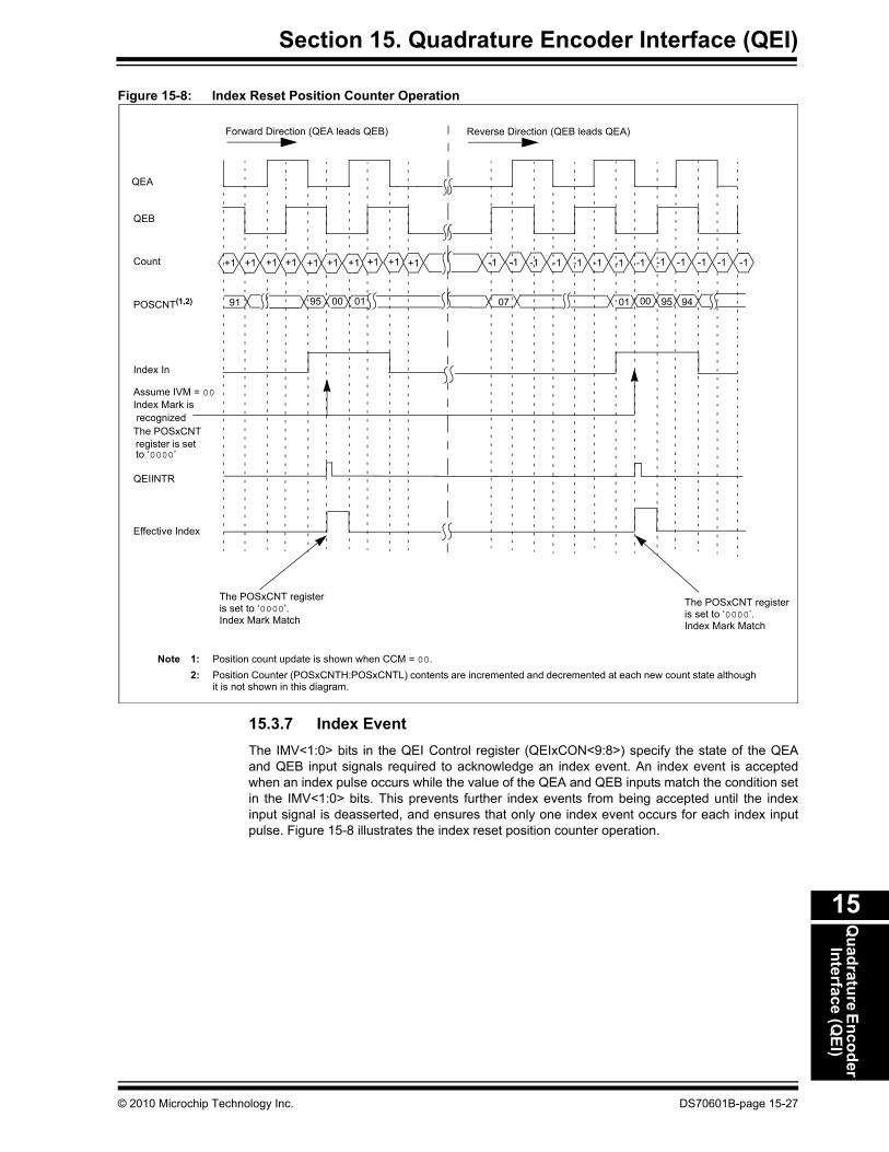
15.3.6 Position ComparatorThe 32-bit Compare register and associated comparator allow the user application to comparethe contents of the position counter to a specified value. The comparator provides two outputs:greater than or equal, and less than or equal. When a suitable condition is met, the comparatorgenerates an interrupt by setting the PCHEQIRQ or PCLEQIRQ bit in the QEI Status register(QEIxSTAT<13> and QEIxSTAT<11>). The comparator output is available on the CNTCMPx pin.The selection of condition is made by the OUTFNC<1:0> bits of the QEI I/O Control register(QEIxIOC<10:9>). The comparator can also be used to reset the position counter when a matchis detected. The selection is made by the PIMOD<2:0> bits of the QEI Control register(QEIxCON<12:10>). Figure 15-8 illustrates the index reset position counter operation.
5 6 0 1 2 3 4 5 1 2 3 4
QEA
QEB
FCY
INTDIV = 000INTxTMRH:INTxTMRL
Contents of the INTxTMRH:INTxTMRL registers are transferred to theINTxHLDH:INTxHLDL registers, and then these registers are reset to ‘0’
56 0
DS70601B-page 15-26 © 2010 Microchip Technology Inc.
Section 15. Quadrature Encoder Interface (QEI)Q
uadrature EncoderInterface (Q
EI)
15
Figure 15-8: Index Reset Position Counter Operation
15.3.7 Index EventThe IMV<1:0> bits in the QEI Control register (QEIxCON<9:8>) specify the state of the QEAand QEB input signals required to acknowledge an index event. An index event is acceptedwhen an index pulse occurs while the value of the QEA and QEB inputs match the condition setin the IMV<1:0> bits. This prevents further index events from being accepted until the indexinput signal is deasserted, and ensures that only one index event occurs for each index inputpulse. Figure 15-8 illustrates the index reset position counter operation.
+1+1 +1 +1 +1 +1 +1 -1 -1 -1 -1 -1 -1 -1 -1 -1 -1 -1 -1
Note 1: Position count update is shown when CCM = 00.2: Position Counter (POSxCNTH:POSxCNTL) contents are incremented and decremented at each new count state although
it is not shown in this diagram.
91
QEA
Count
POSCNT(1,2)
Index Mark is
+1
95 00 01 9507
QEB
Forward Direction (QEA leads QEB) Reverse Direction (QEB leads QEA)
The POSxCNT
Index In
Assume IVM = 00
Effective Index
01 00 94
Index Mark Match
The POSxCNT registeris set to ‘0000’.
QEIINTR
-1+1
recognized
to ‘0000’set
Index Mark Match
The POSxCNT registeris set to ‘0000’.
register is
+1
© 2010 Microchip Technology Inc. DS70601B-page 15-27

dsPIC33E/PIC24E Family Reference Manual
15.3.8 Position Counter Initialization ModesBy using the PIMOD<2:0> bits in the QEI Control register (QEIxCON<12:10>), the userapplication can specify how the position counter is initialized during the module operation.
• Mode 0 - The position counter is unaffected by the index input.• Mode 1 - The position counter is cleared whenever an index input event is detected.• Mode 2 - The position counter is initialized with the contents of the QEIxIC register on the
next detected index input event. When the index event occurs, the PIMOD<2:0> bits are cleared, and then the counter operates in Mode 0.
• Mode 3 - The position counter is initialized with the contents of the QEIxIC register on the next detected index input event following the assertion of the home input. When an index event occurs following the home event, the PIMOD<2:0> bits are cleared, and then the counter operates in Mode 0.
• Mode 4 - The position counter is initialized with the contents of the QEIxIC register on the second detected index input event following the assertion of the home input. When the second index event occurs following the home event, the PIMOD<2:0> bits are cleared, and then the counter operates in Mode 0.
• Mode 5 - The position counter is cleared when the position counter value equals the QEIxIC register value.
• Mode 6 - The position counter is loaded with the contents of the QEIxLEC register when the position counter value equals the QEIxGEC register value and a count up pulse is detected. The counter is loaded with the contents of the QEIxGEC register when the position counter value equals the QEIxLEC register value and a count down pulse is detected.
• Mode 7 - Reserved; the position counter selects the default Mode 0 operation.
15.3.9 Digital Input FilterThe QEI module uses digital noise filters to reject noise on the incoming index and quadraturephase signals. These filters reject low-level noise and large, short duration noise spikes thattypically occur in motor systems.The filtered output signals can change only after an input level has the same value for threeconsecutive rising clock edges. The result is that short noise spikes between rising clock edgesare ignored, and pulses shorter than two clock periods are rejected.The filter clocks rate determines the low passband of the filter. A slower filter clock results in apassband rejecting lower frequencies.The digital filter is enabled by setting the FLTREN bit in the QEI I/O Control register(QEIxIOC<14>). The QFDIV<2:0> bits in the QEI I/O Control register (QEIxIOC<13:11>) selectthe filter clock divider ratio for the clock signal.Figure 15-9 illustrates the simplified block diagram of the digital noise filter.
Figure 15-9: Block Diagram of Digital Noise Filter
QEI Input D Q
TCY
Filtered QEI
CK
Input
Pin
D Q
D Q D Q D Q
Filtered
ClockDividerCircuit
Non-Filtered Signal 0
1
CK
3
CKCK CK CKCKCK
QFDIV<2:0>
CFLTREN
TCY
OR
OR
DS70601B-page 15-28 © 2010 Microchip Technology Inc.

Section 15. Quadrature Encoder Interface (QEI)Q
uadrature EncoderInterface (Q
EI)
15
15.3.10 InterruptsThe following are the sources of QEI interrupts:
• Position counter overflow or underflow event• Velocity counter overflow or underflow event• Position counter initialization process complete• Position counter greater than or equal compare interrupt• Position counter less than or equal compare interrupt• Index event interrupt• Home event interrupt
The QEI Status register (QEIxSTAT) contains the individual interrupt enable bits and thecorresponding interrupt status bits for each interrupt source. A status bit indicates that aninterrupt request has occurred. The module reduces all of the QEI interrupts to a single interruptsignal to the interrupt controller module.
15.4 QEI OPERATION IN POWER-SAVING MODES
15.4.1 Sleep ModeWhen the device enters Sleep mode, QEI operations cease. The POSxCNT register stops at thecurrent value. The QEI does not respond to active signals on the QEA, QEB or INDX pins. TheQEIxCON register remains unchanged.
15.4.2 Idle ModeWhen the device enters Idle mode, the QEISIDL bit in the QEI Control register (QEIxCON<13>)determines whether the QEI module stops in Idle mode or continues to operate in Idle mode.
If QEICSIDL = 1, the QEI module enters into a power-saving mode and performs the samefunctions as in Sleep mode. If QEICSIDL = 0, the module does not enter into a power-savingmode and continues operation in Idle mode.
15.4.3 Doze ModeThe QEI operation in Doze mode is similar as in normal mode.
15.5 EFFECTS OF A RESETA Reset forces module registers to their initial Reset state.
© 2010 Microchip Technology Inc. DS70601B-page 15-29

dsPIC33E/PIC
24E Family R
eference Manual
DS
70601B-page 15-30
© 2010 M
icrochip Technology Inc.
ncoder Interface (QEI) module is provided in
Bit 4 Bit 3 Bit 2 Bit 1 Bit 0 All Resets
CNTPOL GATEN CCM<1:0> 0x0000
EAPOL HOME INDEX QEB QEA 0x000X
LOVIEN HOMIRQ HOMIEN IDXIRQ IDXIEN 0x0000
0x0000
0x0000
0x0000
0x0000
0x0000
0x0000
0x0000
0x0000
0x0000
0x0000
0x0000
0x0000
0x0000
0x0000
0x0000
0x0000
0x0000
15.6 REGISTER MAPA summary of the registers associated with the dsPIC33E/PIC24E family’s Quadrature ETable 15-2.
Table 15-2: QEI Register Map
Name Bit 15 Bit 14 Bit 13 Bit 12 Bit 11 Bit 10 Bit 9 Bit 8 Bit 7 Bit 6 Bit 5
QEIxCON QEIEN — QEISIDL PIMOD<2:0> IMV<1:0> — INTDIV<2:0>
QEIxIOC QCAPEN FLTREN QFDIV<2:0> OUTFNC<1:0> SWPAB HOMPOL IDXPOL QEBPOL Q
QEIxSTAT — — PCHEQIRQ PCHEQIEN PCLEQIRQ PCLEQIEN POSOVIRQ POSOVIEN PCIIRQ PCIIEN VELOVIRQ VE
POSxCNTH POSCNT<31:16>
POSxCNTL POSCNT<15:0>
POSxHLD POSHLD<15:0>
VELxCNT VELCNT<15:0>
INDXxCNTH INDXCNT<31:16>
INDXxCNTL INDXCNT<15:0>
INDXxHLD INDXHLD<15:0>
QEIxICH QEIIC<31:16>
QEIxICL QEIIC<15:0>
QEIxLECH QEILEC<31:16>
QEIxLECL QEILEC<15:0>
QEIxGECH QEIGEC<31:16>
QEIxGECL QEIGEC<15:0>
INTxTMRH INTTMR<31:16>
INTxTMRL INTTMR<15:0>
INTxHLDH INTHLD<31:16>
INTxHLDL INTHLD<15:0>
Legend: x = unknown value on Reset, — = unimplemented, read as ‘0’. Reset values are shown in hexadecimal.

Section 15. Quadrature Encoder Interface (QEI)Q
uadrature EncoderInterface (Q
EI)
15
15.7 DESIGN TIPS
Question 1: How do I configure the software when hardware signals are interchanged?Answer: The HOMPOL, IDXPOL, QEBPOL and QEAPOL bits in the QEIxIOC register
allow the user application to invert the polarity of their associated input signals.The SWPAB bit in the QEIxIOC, when set, swaps the QEA and QEB signals priorto their input into the quadrature decoder. Swapping of the signals reverses thedirection of count. The OUTFNC<1:0> bits in the QEIxIOC register(QEIxIOC<10:9>) allow the user application to output the internal module stateor the status of the position counter comparator on a device pin. The output timingis non-critical because the selected signal is used by the customer’s applicationcircuit, which is external to the device.
Question 2: How do I debug the software using the QEI module?Answer: The QEIxIOC register can be used to configure the external inputs and outputs
of the QEI module.
When setting up or troubleshooting a motion control-based application, theHOME, INDEX, QEB and QEA status bits in the QEIxIOC register can be usedto monitor the individual state of their associated inputs.
A sensor or signal can be connected to the Home input by setting the QCAPENbit in the QEI I/O Control register (QEIxIOC<15>). When set, it allows the userapplication to capture the current position counter value and save it in the QEIxICregister. If the filter is enabled, the Home event is detected when a rising edge ofthe filtered Home signal occurs. When a Home event occurs, an interruptgeneration can be enabled by setting the HOMIEN bit in the QEI Status register(QEIxSTAT<2>).
© 2010 Microchip Technology Inc. DS70601B-page 15-31

dsPIC33E/PIC24E Family Reference Manual
15.8 RELATED APPLICATION NOTESThis section lists application notes that are related to this section of the manual. Theseapplication notes may not be written specifically for the dsPIC33E/PIC24E device family, but theconcepts are pertinent and could be used with modification and possible limitations. The currentapplication notes related to the QEI module are:
Title Application Note #Servo Control of a DC-Brush Motor AN532
PIC18CXXX/PIC16CXXX DC Servomotor Application AN696
Using the dsPIC30F for Vector Control of an ACIM AN908
Note: Please visit the Microchip web site (www.microchip.com) for additional applicationnotes and code examples for the dsPIC33E/PIC24E family of devices.
DS70601B-page 15-32 © 2010 Microchip Technology Inc.

Section 15. Quadrature Encoder Interface (QEI)Q
uadrature EncoderInterface (Q
EI)
15
15.9 REVISION HISTORY
Revision A (June 2009)This is the initial released version of this document.
Revision B (May 2010)This version of the document includes the following updates:
• The document has been renamed from dsPIC33E Family Reference Manual to dsPIC33E/PIC24E Family Reference Manual
• Updated the QEIxCON: QEI Control Register (Register 15-1):- Renamed the register from QEICON to QEIxCON- Updated the PIMOD<12:10> = 111 definition- Changed the bit value definitions of CCM<1:0>
• Updated the QEIxIOC: QEI I/O Control Register (Register 15-2):- Renamed the register from QEIIOC to QEIxIOC- Updated the QCAPEN<15> = 0 definition- Changed the bit value definitions of OUTFNC<10:9>- Changed the bit value definitions of SWPAB<8>- Updated the bit name of QFDIV<13:11>, HOMPOL<7>, IDXPOL<6>, QEBPOL<5>
and QEAPOL<4>- Updated the bit name and bit value definitions of HOME<3>, INDEX<2>, QEB<1> and
QEA<0>• Updated the QEIxSTAT: QEI Status Register (Register 15-3):
- Renamed the register from QEISTAT to QEIxSTAT- Updated the bit name and bit value definitions of PCHEQIRQ<13>, PCLEQIRQ<11>,
PCIIRQ<7>, HOMIRQ<3> and IDXIRQ<1>- Updated the bit name of PCHEQIEN<12>, PCLEQIEN<10> and IDXIEN<0>- Changed the bit value definitions of POSOVIRQ<9> and VELOVIRQ<5>- Add Note 1 to PCIIRQ<7> bit
• Updated the POSxCNTH: Position Counter High Word Register (Register 15-4):- Renamed the register from POSCNTH to POSxCNTH- Changed the bit name of POSCNTH to POSCNT and updated the definition
• Updated the POSxCNTL: Position Counter Low Word Register (Register 15-5):- Renamed the register from POSCNTL to POSxCNTL.- Changed the bit name of POSCNTL to POSCNT and updated the definition
• Updated the POSxHLD: Position Counter Hold Register (Register 15-6):- Renamed the register from POSHLDH to POSxHLD- Updated the bit definition of POSHLD<15:0>
• Updated the VELxCNT: Velocity Counter Register (Register 15-7):- Renamed the register from VELCNT to VELxCNT- Updated the bit name of VELCNT
• Updated the INDXxCNTH: Index Counter High Word Register (Register 15-8):- Renamed the register from IDXCNTH to INDXxCNTH- Changed the bit name of IDXCNTH to INDXCNT and updated the bit definition
• Updated the INDXxCNTL: Index Counter Low Word Register (Register 15-9):- Renamed the register from IDXCNTL to INDXxCNTL.- Changed the bit name and updated the definition of INDXCNT<15:0>- Changed the bit name of IDXCNTL to INDXCNT and updated the bit definition
• Updated the INDXxHLD: Index Counter Hold Register (Register 15-10):- Renamed the register from IDXHLDH to INDXxHLD- Changed the bit name of IDXHLDH to INDXxHLD and updated the bit definition
© 2010 Microchip Technology Inc. DS70601B-page 15-33
dsPIC33E/PIC24E Family Reference Manual
Revision B (May 2010) (Continued)• Updated the QEIxICH: Initialization/Capture High Word Register (Register 15-11):
- Renamed the register from ICCH to QEIxICH- Changed the bit name of ICCH to QEIIC and updated the bit definition
• Updated the QEIxICL: Initialization/Capture Low Word Register (Register 15-12):- Renamed the register from ICCL to QEIxICL- Changed the bit name of ICCL to QEIIC and updated the bit definition
• Added the QEIxLECH: Less Than or Equal Compare High Word Register (Register 15-13)• Added the QEIxLECL: Less Than or Equal Compare Low Word Register (Register 15-14)• Added the QEIxGECH: Greater Than or Equal Compare High Word Register
(Register 15-15)• Added the QEIxGECL: Greater Than or Equal Compare Low Word Register
(Register 15-16)• Updated the INTxTMRH: Interval Timer High Word Register (Register 15-17):
- Renamed the register from INTTMRH to INTxTMRH- Changed the bit name of INTTMRH to INTTMR
• Updated the INTxTMRL: Interval Timer Low Word Register (Register 15-18):- Renamed the register from INTTMRL to INTxTMRL- Changed the bit name of INTTMRL to INTTMR
• Updated the INTxHLDH: Interval Timer Hold High Word Register (Register 15-19):- Renamed the register from INTHLDH to INTxHLDH- Changed the bit name of INTHLDH to INTHLD
• Updated the INTxHLDL: Interval Timer Hold Low Word Register (Register 15-20):- Renamed the register from INTHLDL to INTxHLDL- Changed the bit name of INTHLDL to INTHLD
• Deleted the CMPLH: Compare Register High Word and CMPLL: Compare Register Low Word registers
• All new register names and acronyms are updated throughout the document• Updated all the timing diagrams in the document• Updated the content in 15.3.7 “Index Event”• Updated the bulleted list in 15.3.10 “Interrupts”• Deleted UPDN pin in 15.4.1 “Sleep Mode”• Minor typographical and formatting corrections were made throughout the document
DS70601B-page 15-34 © 2010 Microchip Technology Inc.
Note the following details of the code protection feature on Microchip devices:• Microchip products meet the specification contained in their particular Microchip Data Sheet.
• Microchip believes that its family of products is one of the most secure families of its kind on the market today, when used in the intended manner and under normal conditions.
• There are dishonest and possibly illegal methods used to breach the code protection feature. All of these methods, to our knowledge, require using the Microchip products in a manner outside the operating specifications contained in Microchip’s Data Sheets. Most likely, the person doing so is engaged in theft of intellectual property.
• Microchip is willing to work with the customer who is concerned about the integrity of their code.
• Neither Microchip nor any other semiconductor manufacturer can guarantee the security of their code. Code protection does not mean that we are guaranteeing the product as “unbreakable.”
Code protection is constantly evolving. We at Microchip are committed to continuously improving the code protection features of ourproducts. Attempts to break Microchip’s code protection feature may be a violation of the Digital Millennium Copyright Act. If such actsallow unauthorized access to your software or other copyrighted work, you may have a right to sue for relief under that Act.
Information contained in this publication regarding deviceapplications and the like is provided only for your convenienceand may be superseded by updates. It is your responsibility toensure that your application meets with your specifications.MICROCHIP MAKES NO REPRESENTATIONS ORWARRANTIES OF ANY KIND WHETHER EXPRESS ORIMPLIED, WRITTEN OR ORAL, STATUTORY OROTHERWISE, RELATED TO THE INFORMATION,INCLUDING BUT NOT LIMITED TO ITS CONDITION,QUALITY, PERFORMANCE, MERCHANTABILITY ORFITNESS FOR PURPOSE. Microchip disclaims all liabilityarising from this information and its use. Use of Microchipdevices in life support and/or safety applications is entirely atthe buyer’s risk, and the buyer agrees to defend, indemnify andhold harmless Microchip from any and all damages, claims,suits, or expenses resulting from such use. No licenses areconveyed, implicitly or otherwise, under any Microchipintellectual property rights.
© 2010 Microchip Technology Inc.
Trademarks
The Microchip name and logo, the Microchip logo, dsPIC, KEELOQ, KEELOQ logo, MPLAB, PIC, PICmicro, PICSTART, PIC32 logo, rfPIC and UNI/O are registered trademarks of Microchip Technology Incorporated in the U.S.A. and other countries.
FilterLab, Hampshire, HI-TECH C, Linear Active Thermistor, MXDEV, MXLAB, SEEVAL and The Embedded Control Solutions Company are registered trademarks of Microchip Technology Incorporated in the U.S.A.
Analog-for-the-Digital Age, Application Maestro, CodeGuard, dsPICDEM, dsPICDEM.net, dsPICworks, dsSPEAK, ECAN, ECONOMONITOR, FanSense, HI-TIDE, In-Circuit Serial Programming, ICSP, Mindi, MiWi, MPASM, MPLAB Certified logo, MPLIB, MPLINK, mTouch, Octopus, Omniscient Code Generation, PICC, PICC-18, PICDEM, PICDEM.net, PICkit, PICtail, REAL ICE, rfLAB, Select Mode, Total Endurance, TSHARC, UniWinDriver, WiperLock and ZENA are trademarks of Microchip Technology Incorporated in the U.S.A. and other countries.
SQTP is a service mark of Microchip Technology Incorporated in the U.S.A.
All other trademarks mentioned herein are property of their respective companies.
© 2010, Microchip Technology Incorporated, Printed in the U.S.A., All Rights Reserved.
Printed on recycled paper.
ISBN: 978-1-60932-203-8
DS70601B-page 35
Microchip received ISO/TS-16949:2002 certification for its worldwide headquarters, design and wafer fabrication facilities in Chandler and Tempe, Arizona; Gresham, Oregon and design centers in California and India. The Company’s quality system processes and procedures are for its PIC® MCUs and dsPIC® DSCs, KEELOQ® code hopping devices, Serial EEPROMs, microperipherals, nonvolatile memory and analog products. In addition, Microchip’s quality system for the design and manufacture of development systems is ISO 9001:2000 certified.
DS70601B-page 36 © 2010 Microchip Technology Inc.
AMERICASCorporate Office2355 West Chandler Blvd.Chandler, AZ 85224-6199Tel: 480-792-7200 Fax: 480-792-7277Technical Support: http://support.microchip.comWeb Address: www.microchip.comAtlantaDuluth, GA Tel: 678-957-9614 Fax: 678-957-1455BostonWestborough, MA Tel: 774-760-0087 Fax: 774-760-0088ChicagoItasca, IL Tel: 630-285-0071 Fax: 630-285-0075ClevelandIndependence, OH Tel: 216-447-0464 Fax: 216-447-0643DallasAddison, TX Tel: 972-818-7423 Fax: 972-818-2924DetroitFarmington Hills, MI Tel: 248-538-2250Fax: 248-538-2260KokomoKokomo, IN Tel: 765-864-8360Fax: 765-864-8387Los AngelesMission Viejo, CA Tel: 949-462-9523 Fax: 949-462-9608Santa ClaraSanta Clara, CA Tel: 408-961-6444Fax: 408-961-6445TorontoMississauga, Ontario, CanadaTel: 905-673-0699 Fax: 905-673-6509
ASIA/PACIFICAsia Pacific OfficeSuites 3707-14, 37th FloorTower 6, The GatewayHarbour City, KowloonHong KongTel: 852-2401-1200Fax: 852-2401-3431Australia - SydneyTel: 61-2-9868-6733Fax: 61-2-9868-6755China - BeijingTel: 86-10-8528-2100 Fax: 86-10-8528-2104China - ChengduTel: 86-28-8665-5511Fax: 86-28-8665-7889China - ChongqingTel: 86-23-8980-9588Fax: 86-23-8980-9500China - Hong Kong SARTel: 852-2401-1200 Fax: 852-2401-3431China - NanjingTel: 86-25-8473-2460Fax: 86-25-8473-2470China - QingdaoTel: 86-532-8502-7355Fax: 86-532-8502-7205China - ShanghaiTel: 86-21-5407-5533 Fax: 86-21-5407-5066China - ShenyangTel: 86-24-2334-2829Fax: 86-24-2334-2393China - ShenzhenTel: 86-755-8203-2660 Fax: 86-755-8203-1760China - WuhanTel: 86-27-5980-5300Fax: 86-27-5980-5118China - XianTel: 86-29-8833-7252Fax: 86-29-8833-7256China - XiamenTel: 86-592-2388138 Fax: 86-592-2388130China - ZhuhaiTel: 86-756-3210040 Fax: 86-756-3210049
ASIA/PACIFICIndia - BangaloreTel: 91-80-3090-4444 Fax: 91-80-3090-4123India - New DelhiTel: 91-11-4160-8631Fax: 91-11-4160-8632India - PuneTel: 91-20-2566-1512Fax: 91-20-2566-1513Japan - YokohamaTel: 81-45-471- 6166 Fax: 81-45-471-6122Korea - DaeguTel: 82-53-744-4301Fax: 82-53-744-4302Korea - SeoulTel: 82-2-554-7200Fax: 82-2-558-5932 or 82-2-558-5934Malaysia - Kuala LumpurTel: 60-3-6201-9857Fax: 60-3-6201-9859Malaysia - PenangTel: 60-4-227-8870Fax: 60-4-227-4068Philippines - ManilaTel: 63-2-634-9065Fax: 63-2-634-9069SingaporeTel: 65-6334-8870Fax: 65-6334-8850Taiwan - Hsin ChuTel: 886-3-6578-300Fax: 886-3-6578-370Taiwan - KaohsiungTel: 886-7-536-4818Fax: 886-7-536-4803Taiwan - TaipeiTel: 886-2-2500-6610 Fax: 886-2-2508-0102Thailand - BangkokTel: 66-2-694-1351Fax: 66-2-694-1350
EUROPEAustria - WelsTel: 43-7242-2244-39Fax: 43-7242-2244-393Denmark - CopenhagenTel: 45-4450-2828 Fax: 45-4485-2829France - ParisTel: 33-1-69-53-63-20 Fax: 33-1-69-30-90-79Germany - MunichTel: 49-89-627-144-0 Fax: 49-89-627-144-44Italy - Milan Tel: 39-0331-742611 Fax: 39-0331-466781Netherlands - DrunenTel: 31-416-690399 Fax: 31-416-690340Spain - MadridTel: 34-91-708-08-90Fax: 34-91-708-08-91UK - WokinghamTel: 44-118-921-5869Fax: 44-118-921-5820
WORLDWIDE SALES AND SERVICE
01/05/10