dt-900 hardware manual - protecs.co.kr file4 1. overview 1.1 product overview the dt-900 has been...
TRANSCRIPT
DT-900
Hardware Manual( Version 1.10 )
CASIO Computer Co., Ltd.Copyright ©1999. All rights reserved.
April 1999

2
Table of Contents
Chapter 1 Overview 41.1 Product Overview 41.2 Feature 41.2.1 Hand-held Operability 41.2.2 Improved Compatibility and AP Development Environment 41.2.3 Improved Resistance to Environment 41.2.4 Systematization 51.2.5 Improved Ease of Operation 51.2.6 Basic Performance 5
Chapter 2 Appearance 62.1 External View 62.1.1 DT-900M51E 62.1.2 DT-900M50E 62.2 External View of Option 72.2.1 Satellite I/O Box (DT-964IO-E) 72.2.2 Rechargeable Battery Pack (DT-923LI) 7
Chapter 3 System Configuration 83.1 Available Model 83.2 System Diagram 93.3 Option 10
Chapter 4 General Specification 114.1 Specification of Each Block 114.2 Key Layout 144.3 Consumables 154.4 Safety Standard 15
Chapter 5 Electrical Specification 16Chapter 6 Environment Specification 17Chapter 7 Mechanical Specification 18
7.1 Mechanical Strength 18Chapter 8 Reliability and Durability 19
8.1 Reliability 198.2 Durability 19
Chapter 9 Cable 209.1 Model Name and Use 209.2 Signal and Wiring 21
Chapter 10 DT-960IO-E (Basic I/O Box) 2410.1 Overview 2410.1.1 Features 2410.2 External View 2510.3 Diemsions and Weight 2610.4 Block Diagram 2710.5 Specification 2810.5.1 General Specification 2810.5.2 Electric Specification 3110.5.3 Environment Specification 3110.5.4 Mechanical Strength 3210.6 Transport and Storage 3210.6.1 Transport 3210.6.2 Storage 32

3
10.7 Reliability, Durability and Safety Standard 3310.7.1 Reliability 3310.7.2 Durability 3310.7.3 Safety Standard 3310.8 Chain Connection 3410.8.1 Configuration and Operating Conditions 34
Basic I/O Boxes and Host P/C 35Multiple Basic I/O Boxes 36
10.8.2 Cable Specification 37Cable for Chain Connection (short distance) 38Cable for Chain Connection (long distance) 38
10.8.3 Notes about Chain Connection 39Chapter 11 DT-964IO-E (Satellite I/O Box) 40
11.1 Overview 4011.1.1 Features 4011.2 External View 4111.3 Dimensions and Weight 4211.4 Block Diagram 4311.5 Specification 4411.5.1 General Specification 4411.5.2 Electric Specification 4811.5.3 Environment Specifcation 4811.5.4 Mechanical Strength 4811.6 Transport and Storage 4911.6.1 Transport (packing) 4911.6.2 Storage 4911.7 Reliability, Durability and Safety Standard 5011.7.1 Reliability 5011.7.2 Durability 5011.7.3 Safety Standard 5011.8 Chain Connection 5111.8.1 Configuration and Operating Conditions 51
Satellite I/O Box and Host P/C with External Device 51Master I/O Box, Satellite I/O Boxes and Host P/C 52Multiple Satellite I/O Boxes and Host P/C 53For Downloading 54
11.8.2 Cable Specification 55Cable for Short Distance 55Cable for Chain Connection 56
11.8.3 Precautions 57Chapter 12 DT-969CHG-E (I/O Box Type Recharger) 58
12.1 Overview 5812.1.1 Feature 5812.2 External View 5912.3 Dimensions and Weight 6012.4 Block Diagram 6012.5 Specification 6112.5.1 General Specification 6112.5.2 Electric Specification 6212.5.3 Environment Specification 6212.5.4 Mechanical Strength 6212.6 Transport and Storage 6312.6.1 Transport (packaging) 6312.6.2 Storage 6312.7 Reliability, Durability and Safety Standard 6412.7.1 Reliability 6412.7.2 Durability 6412.7.3 Safety Standard 64
4
1. Overview
1.1 Product Overview
The DT-900 has been designed to be a superior model over the DT-700, which is the basic model ofa data collection terminal. While maintaining compatibility with conventional machines, the DT-900has greater screen resolution (128 x 64 dots), improved data processing capabilities, and multiplepower supply support. Also, the model (DT-900M50E) with a downward pointing nose that has beenadded to the line up, has improved the ease-of-operation in scanning barcodes on horizontal surfaces.These various models allow model selection according to user needs.
1.2 Feature
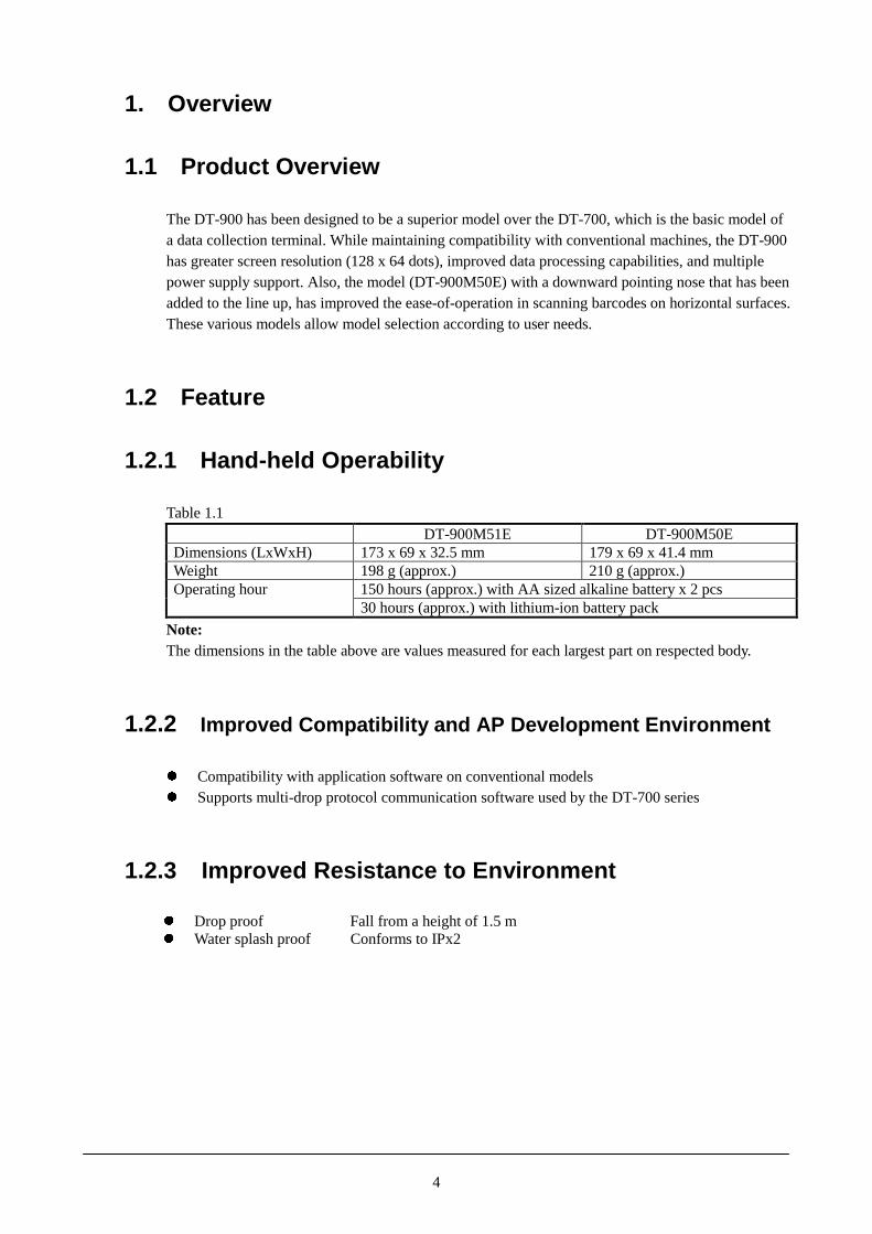
1.2.1 Hand-held Operability
Table 1.1DT-900M51E DT-900M50E
Dimensions (LxWxH) 173 x 69 x 32.5 mm 179 x 69 x 41.4 mmWeight 198 g (approx.) 210 g (approx.)
150 hours (approx.) with AA sized alkaline battery x 2 pcsOperating hour30 hours (approx.) with lithium-ion battery pack
Note:The dimensions in the table above are values measured for each largest part on respected body.
1.2.2 Improved Compatibility and AP Development Environment
� Compatibility with application software on conventional models� Supports multi-drop protocol communication software used by the DT-700 series
1.2.3 Improved Resistance to Environment
� Drop proof Fall from a height of 1.5 m� Water splash proof Conforms to IPx2
5
1.2.4 Systematization
� OS µITRON version 2.0� Infrared high-speed communication IrDA Ver 1.2 and Casio original infrared communication� 2-way power supply Lithium-ion rechargeable battery and LR6 alkaline dry cell
1.2.5 Improved Ease of Operation
� High resolution display (compatible with DT-700)128 x 64 dots and easy-to-see icons9 different font types (6x6, 8x8, 10x10, 12x6, 12x12, 16x8, 16x16, 20x10, 20x20 dots)make possible to have the compatibility with DT-700.Display with 20 digits is possible on DT-900.
� Measures for adjacent barcodesLaser beam swing control
� Ease of key operationMulti-function keys + side trigger keys
1.2.6 Basic Performance
� High-performance CPUCPU: SH7020 32-bit RISC (4.9152/2.4576/1.2288 MHz)
� Large-capacity memoryMain RAM (D-RAM) --------------------------------------- 2 MBExecutable code + user data storage memory (Flash) ----- 2 MB
6
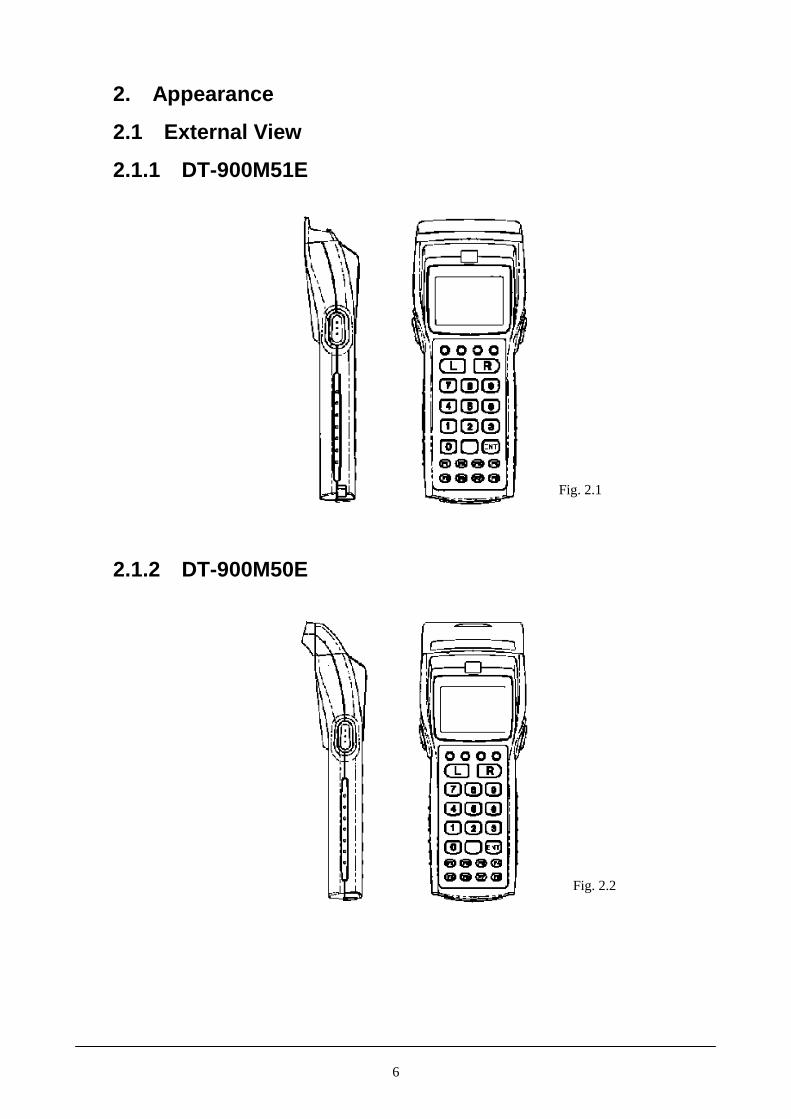
2. Appearance
2.1 External View
2.1.1 DT-900M51E
2.1.2 DT-900M50E
Fig. 2.1
Fig. 2.2

7
2.2 External View of Option
2.2.1 Satellite I/O Box (DT-964IO-E)
2.2.2 Rechargeable Battery Pack (DT-923LI)
Fig. 2.3
Fig. 2.4
8
3. System Configuration
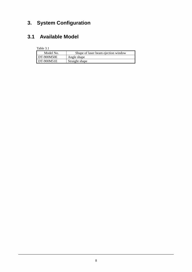
3.1 Available Model
Table 3.1Model No. Shape of laser beam ejection window
DT-900M50E Angle shapeDT-900M51E Straight shape
9
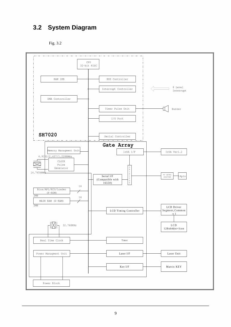
3.2 System Diagram
CPU32-bit RISC
RAM 1KB
DMA Contoroller
BUS Controller
Bios/APL/KCG/Loader(F-ROM)
2MB
MAIN RAM (D-RAM)
2MB
T imer
Laser Uni t
Ma t r i x KEY
LCD Dr iverS egm e n t , C o m m o n
x 1
L C D128x64dot+ Icon
Power Block
32.768KHz
14.7456MHz
Gate Array
SH7020
Buzzer
8 LevelInterrupt
IrDA Ver1.2
Serial I /F(Compat ib le w i th
16550)
LCD T iming Cont ro l le r
Real Time Clock
Power Managment Unit Laser I /F
Key I /F
Interrupt Controller
Timer Pulse Unit
I/O Port
14pin
CLOCKPulse
Genelator
4.9152/2.457/1.2288MHz
Serial Controller
5V LEVELSHIFTER
SELECTOR
lrDA I/F
16
16
Memory Managment Unit
Fig. 3.2

10
3.3 Option
Table 3.2 List of the optionsModel No. Product Specification
DT-965IO-E Master I/O Box SCSI interfaceDT-966IO-E Master I/O Box LAN interfaceDT-964IO-E Satellite I/O BoxDT-960IO-E Basic I/O BoxDT-969CHG-E Recharger I/O Box type rechargerDT-923LI Battery pack Lithium-ion rechargeable batteryDT-891SCSI SCSI cable Centronics half 50 pinsDT-892SCSI SCSI cable Centronics 50 pinsDT-893SCSI SCSI cable Half 50 pinsDT-9020ADP-G AC adaptor 230VAC. For DT-960IO-E and DT-969CHG-EDT-9020ADP-U AC adaptor 120VAC. For DT-960IO-E and DT-969CHG-EDT-825ADP-G AC adaptor 230VAC. For DT-965IO-E/966IO-E and DT-964IO-EDT-825ADP-U AC adaptor 120VAC. For DT-965IO-E/966IO-E and DT-964IO-EDT-782RSC RS-232C cable Cross cable for DT-960IO-E 14-pin/25-pin maleDT-783RSC RS-232C cable Cross cable for DT-960IO-E 14-pin/25-pin femaleDT-787AX RS-232C cable Cross cable for DT-960IO-E 14-pin/19-pin femaleLVC91 (note 2) RS-232C cable Level converter cross cable with D-Sub 9-pin femaleLVC92 (note 2) RS-232C cable Level converter straight cable with D-Sub 25-pin maleDT-881RSC RS-232C cable Straight cable for DT-964IO-E 9-pin female/25-pin maleDT-882RSC RS-232C cable Cross cable for DT-964IO-E/PC 9-pin female/25-pin maleDT-883RSC RS-232C cable Cross cable for DT-964IO-E/PC 9-pin female/25-pin femaleDT-887AX RS-232C cable Cross cable for DT-964IO-E/PC 9-pin female/9-pin femaleDT-788RSC RS-485 cable Cable for DT-960IO-E (connection under daisy-chain)DT-888RSC RS-422 cable Cable for DT-964IO-E (connection under daisy-chain)DT-810PR Printer cable For TEC IrDA printer (model; B-211-GH24-QM)
Notes:1. Information in the table above is as of December 1998.2. The model names are tentative.

11
4. General Specification
4.1 Specification of Each Block
Table 4.1 Specifications of each blockBlock Item Specification Remark
CPU and peripheralsBuilt-in chip HD6437020SU01XNumber of access bits 32-bit RISC
CPU
Operation frequency 4.92/2.46/1.23 MHzBuilt-in chip KM416U1004CT-L7Capacity 16 Mbits (or 2 Mbytes)
RAM
Access time 70 nsec.Bult-in chip TE28F160B3B90Capacity 16 Mbits (or 2 Mbytes)
F-ROM
Access time 90 nsBuilt-in chip SLA407AF0SOperation frequency 14.7456 MHz/32.768 KHz
Bus control [BCU]Memory control [MMU]Calendar/clock [RTC]Serial I/F [SIF]Power management [PMU]Laser I/F [LCU]Timer [GAITU]Key I/F [KBC]
Gate array
Function
Display I/F [LCDC]Clock Year/month/day/hour/minute/
second/day of the week/leap year
with auto self-startfunction
Alarm Hour/minute
Clock�Calendar
Accuracy Monthly error of ±60 secondsBuilt-in chip CB-09FP
Step/Setup 4 steps(Loud/Middle/Small/OFF)/Software setup
Sound volume
Max. volume 75 dB (at a distance of 30 cm)Key input sound 2,696 Hz
Buzzer
ToneRead with laser 4,096 HzType STN liquid crystal (semi-
transparent) with phasecompensation film
No. of dots 128 x 64 dots
LCDpanel
Dot pitch 0.30 x 0.35 mmDisplayed character types ANK/JIS Level I, II Kanji/Extra
/User-defined characters6-dot font 6x6 21 columns x 10 lines8-dot font 8x8 16 columns x 8 lines
10-dot font 10x10 12 columns x 6 lines12-dot font 12x12 10 columns x 5 lines
6x12 20 columns x 5 lines16-dot font 16x16 8 columns x 4 lines
8x16 16 columns x 4 lines20-dot font 20x20 6 columns x 3 lines
No. ofcharacters
10x20 12 columns x 3 linesLCDD LH155BF (SHARP)
Display
Graphic RAM 1 Kbyte (built-in LCDD)
Continues to the next page.
12
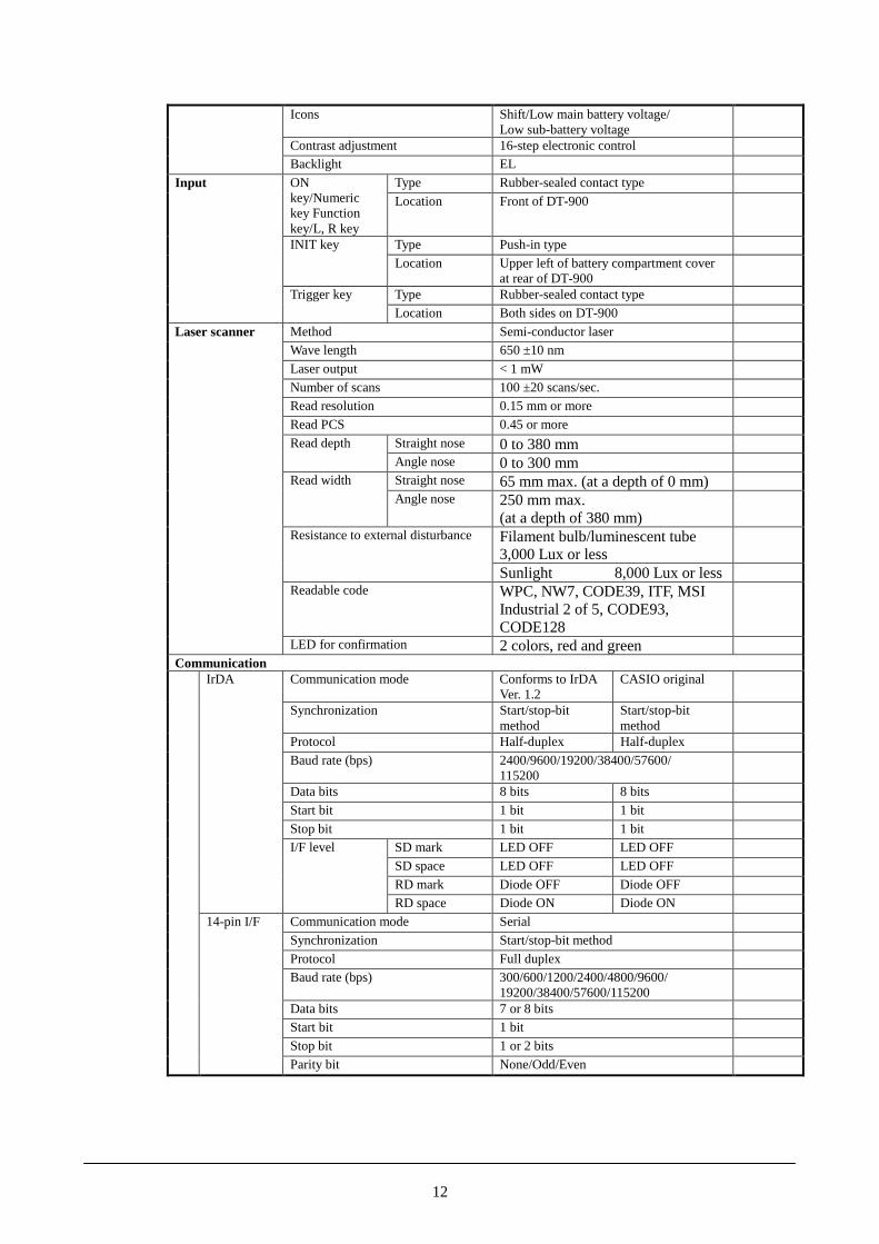
Icons Shift/Low main battery voltage/Low sub-battery voltage
Contrast adjustment 16-step electronic controlBacklight EL
Type Rubber-sealed contact typeONkey/Numerickey Functionkey/L, R key
Location Front of DT-900
Type Push-in typeINIT key
Location Upper left of battery compartment coverat rear of DT-900
Type Rubber-sealed contact type
Input
Trigger key
Location Both sides on DT-900
Method Semi-conductor laserWave length 650 ±10 nm
Laser output < 1 mW
Number of scans 100 ±20 scans/sec.Read resolution 0.15 mm or more
Read PCS 0.45 or more
Straight nose 0 to 380 mmRead depth
Angle nose 0 to 300 mmStraight nose 65 mm max. (at a depth of 0 mm)Read width
Angle nose 250 mm max.(at a depth of 380 mm)Filament bulb/luminescent tube3,000 Lux or less
Resistance to external disturbance
Sunlight 8,000 Lux or lessReadable code WPC, NW7, CODE39, ITF, MSI
Industrial 2 of 5, CODE93,CODE128
Laser scanner
LED for confirmation 2 colors, red and greenCommunication
Communication mode Conforms to IrDAVer. 1.2
CASIO original
Synchronization Start/stop-bitmethod
Start/stop-bitmethod
Protocol Half-duplex Half-duplex
Baud rate (bps) 2400/9600/19200/38400/57600/115200
Data bits 8 bits 8 bits
Start bit 1 bit 1 bit
Stop bit 1 bit 1 bitSD mark LED OFF LED OFF
SD space LED OFF LED OFF
RD mark Diode OFF Diode OFF
IrDA
I/F level
RD space Diode ON Diode ON
Communication mode Serial
Synchronization Start/stop-bit method
Protocol Full duplexBaud rate (bps) 300/600/1200/2400/4800/9600/
19200/38400/57600/115200Data bits 7 or 8 bitsStart bit 1 bit
Stop bit 1 or 2 bits
14-pin I/F
Parity bit None/Odd/Even

13
CommunicationSD mark 0 V
SD space 5 VRD mark 0 V
I/F level
RD space 5 V
No. 1 - NC No. 8 - CSNo. 2 - NC No. 9 - CD
No. 3 - ER No. 10 - RD
No. 4 - RS No. 11 - GND
No. 5 - SD No. 12 - CINo. 6 - GND No. 13 - NC
Signal pin assignment
No. 7 - DR No. 14 - GND
Connector (at DT-900 side) TX20A-14R-D2LT-A1L (by Japan Aviation Elect. Industry)
14-pin I/F
Connector (at cable side) TX20A-14R-D2SF1-A1LP (by Japan Aviation Elect. Industry)Power supply
Standard OptionBattery typeLR6 alkaline drycell x 2
Lithium-ion batterypack x 1
Nominal voltage DC 1.5 V x 2 DC 3.6 VNominal capacity 600 mAhOperating hours (Note 4) Approx. 150 Approx. 30 Note 1Operating hours (Note 4) :at low temperature
Approx. 60 Approx. 25 Note 2
Condition on operating hours 20 (sleep): 1 (operation): 1(laser)Backup period (Note 4) :with only main battery
5 months 1.5 months Note 1
Batteryforoperation
Backup period :with only main battery (LB1)
10 days 1.5 days Note 3
Battery type Button-type lithium battery (CR2032) x 1Nominal voltage DC 3.0 VNominal capacity 210 mAh (with Panasonic battery)
BackupBattery(sub-battery) Backup hours
(with only sub-battery)1 month Note 1
Function Operation statusLB0 (main battery) Absence of battery Forced OFFLB1 (main battery) Battery used Operable
Lowbatteryvoltagealarm
Type
LB2 (sub-battery) Battery used or notpresent
Backup notpossible
Notes:1. at room temperature of 25�2. at low temperature of -5�3. at room temperature of 25�4. with new battery and fully charged with CASIO DT-969CHG-E before use.
17
814

14
Detected voltage Alkaline Lithium-ionLB0 (main battery) 1.5 V 2.8 V
LB1 (main battery) 2.1 V 3.3 V
Lowbatteryvoltagealarm LB2 (sub-battery) 2.7 V
Pin No.1 VCHG Recharging terminal 4.2 V, 300 mAmax.
Pin No.2 XIRCNT I/O Box control signalPin No.3 VADP Power supply terminal 5 V, 400 mA
max.
Rechargingterminalfunction
Pin No.4 GND Ground
4.2 Key Layout
Fig. 4.1 Key layout (front view)
Note:Side-trigger keys are located on both side faces.
�
� � �
� � �
�
� � ���
��
�
��
��
��
��
��
��
�
SP •£ •¥ BL
- •© •¨ DEL
••/+ •“•F•–
STU VWX YZ-
JLK MNO POR
ABC DEF GHI
S BS CLR PW
41

15
4.3 Consumables
Table 4.2Item Specification
LR6 alkaline dry cell LR6Button-type lithium battery CR2032
4.4 Safety Standard
Table 4.3 List of the applicable standardsStandard Remark
EMI EN-55022 Class BCommon immunity EN-50082-1Safety EN-60950 DT-9020ADP is used for the test.Laser IEC Class II
Note:EMI level for Master I/O Boxes is Class A and that of Basic I/O Box and Satellite I/O Box isClass B.

16
5. Electrical Specification
Table 5.1Item Specification Remark
Power consumption 0.7 W On DT-900 onlyLR6 alkaline dry cell x 2Power supplyLithium-ion battery pack
Static-electricity strength 250 pF, 100 ohmMalfunction 5 KVDestruction 10 KV
Line noise strength N/APower interruption N/A
Dielectric strength N/AInsulation resistance N/A
Terminal noise voltage N/ANoise radiant intensity CE marking
N/A ; not applicable
17
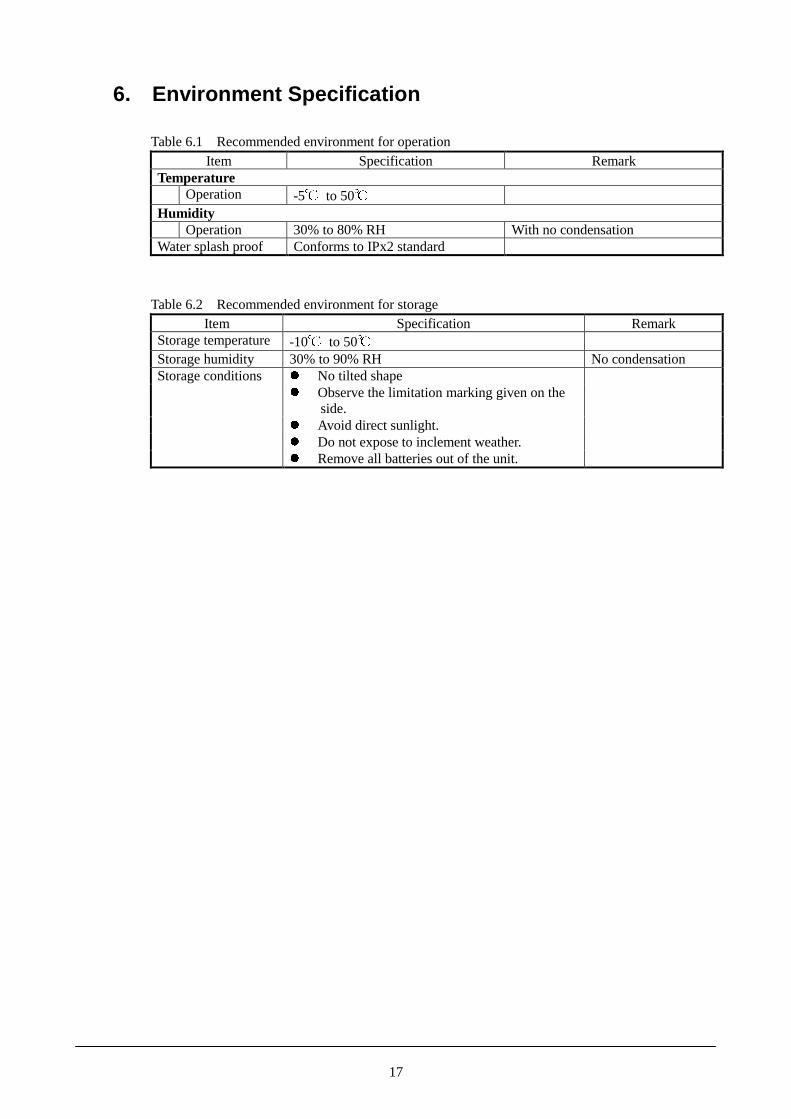
6. Environment Specification
Table 6.1 Recommended environment for operationItem Specification Remark
TemperatureOperation -5� to 50�
HumidityOperation 30% to 80% RH With no condensation
Water splash proof Conforms to IPx2 standard
Table 6.2 Recommended environment for storageItem Specification Remark
Storage temperature -10� to 50�Storage humidity 30% to 90% RH No condensation
� No tilted shape� Observe the limitation marking given on the
side.� Avoid direct sunlight.� Do not expose to inclement weather.
Storage conditions
� Remove all batteries out of the unit.

18
7. Mechanical Specification
7.1 Mechanical Strength
Table 7.1Item Specification Remark
Resistance to vibration 0.15 G or less Conditions:� At frequency between 10 and 55 Hz� In the X,Y, and Z directions� Reciprocally for 30 minutes
Shock-proof 150 cm Fall from height of 150 cm

19
8. Reliability And Durability
8.1 Reliability
Table 8.1Item Specification Remark
MTBF of electronic parts 13,500 hoursBacklight 3,000 hours Until the brightness of the backlight
becomes half-value of the full brightness(20�/60%RH).
Laser scanner 5,000 hours
8.2 Durability
Table 8.2Item Specification Remark
KeyPower switch 300,000 or more activationsMatrix key 300,000 or more activationsTrigger key 1,000,000 or more activations
Connector14-pin 3,500 or more connections/disconnections
Battery compartment lid 5,000 or more openings/closings Including the lockbutton.
Power supply sectionOperating battery 5,000 or more removals/replacements
Recharging terminal (I/O Box) 5,000 or more mountings/dismountings

20
9. Cable
9.1 Model Name and Use
Model Name UseDT-881RSC An RS-232C cable which connects between the RS-232C interface of DT-964IO-E
(Satellite I/O Box) and a modem.DT-882RSC An RS-232C cable which connects between the RS-232C interface of DT-964IO-E
(Satellite I/O Box) and a P/C.DT-883RSC An RS-232C cable which connects between the RS-232C interface of DT-964IO-E
(Satellite I/O Box) and a P/C.DT-887AX An RS-232C cable which connects between the RS-232C interface of DT-964IO-E
(Satellite I/O Box) and a P/C.DT-888RSC A cable to connect between DT-964IO-Es. This cable is used to connect multiple
Satellite I/O Boxes under daisy-chain mode.DT-782RSC An RS-232C cable which connects between the RS-232C interface of DT-960IO-E
(Basic I/O Box) and a P/C.DT-783RSC An RS-232C cable which connects between the RS-232C interface of DT-960IO-E
(Basic I/O Box) and a P/C.DT-787AX An RS-232C cable which connects between the RS-232C interface of DT-960IO-E
(Basic I/O Box) and a P/C.DT-788RSC A cable to connect between DT-960IO-Es. This cable is used to connect multiple
Basic I/O Boxes under daisy-chain mode.LVC91 (note) A cable to connect between DT-900 and a modem. This cable is with the level
converter and with “D-Sub 9-pin female” at modem side.LVC92 (note) A cable to connect between DT-900 and a modem. This cable is with the level
converter and with “D-Sub 25-pin male” at modem side.
Note:The model names are tentative.

21
9.2 Signal and Wiring
� DT-881RSC (Straight)
I/O Box (9-pin female) side External peripheral (25-pin male) side
Signal Pin Pin SignalSD 3 2 SDRD 2 3 RDRS 7 4 RSCS 8 5 CSDR 6 6 DRSG 5 7 SGCD 1 8 CDER 4 20 ERCI 9 22 CI
1 FGCase Case
� DT-882RSC (Cross)
I/O Box (9-pin female) side External peripheral (25-pin male) side
Signal Pin Pin SignalSD 3 2 SDRD 2 3 RDRS 7 4 RSCS 8 5 CSDR 6 6 DRSG 5 7 SGCD 1 8 CDER 4 20 ERCI 9 22 CI
1 FGCase Case
� DT-883RSC (Cross)
I/O Box (9-pin female) side External peripheral (25-pin male) side
Signal Pin Pin SignalSD 3 2 SDRD 2 3 RDRS 7 4 RSCS 8 5 CSDR 6 6 DRSG 5 7 SGCD 1 8 CDER 4 20 ERCI 9 22 CI
1 FGCase Case

22
� DT-887AX (Cross)
I/O Box (9-pin female) side External peripheral (9-pin female) side
Signal Pin Pin SignalSD 3 3 SDRD 2 2 RDRS 7 7 RSCS 8 8 CSDR 6 6 DRSG 5 5 SGCD 1 1 CDER 4 4 ERCI 9 9 CI
Case Case
� DT-888RSC (Cross for RS-422)
I/O Box (C-OUT ) side I/O Box (C-IN) side
Signal Pin Pin SignalORS+ 1 1 IRS+ORS- 2 2 IRS-OSD+ 3 3 ISD+OSD- 4 4 ISD-IRD+ 5 5 ORD+IRD- 6 6 ORD-
� DT-782RSC (Cross)
I/O Box (14-pin female) side External peripheral (25-pin male) side
Signal Pin Pin SignalFG 1 1 FGSD 3 2 SDRD 5 3 RDRS 7 4 RSCS 9 5 CSCD 13 8 CDER 8 20 ERDR 11 6 DRSG 14 7 SGFG Case 1 FG
� DT-783RSC (Cross)
I/O Box (14-pin female) side External peripheral (25-pin female) side
Signal Pin Pin SignalFG 1 1 FGSD 3 2 SDRD 5 3 RDRS 7 4 RSCS 9 5 CSCD 13 8 CDER 8 20 ERDR 11 6 DRSG 14 7 SGFG Case 1 FG
23
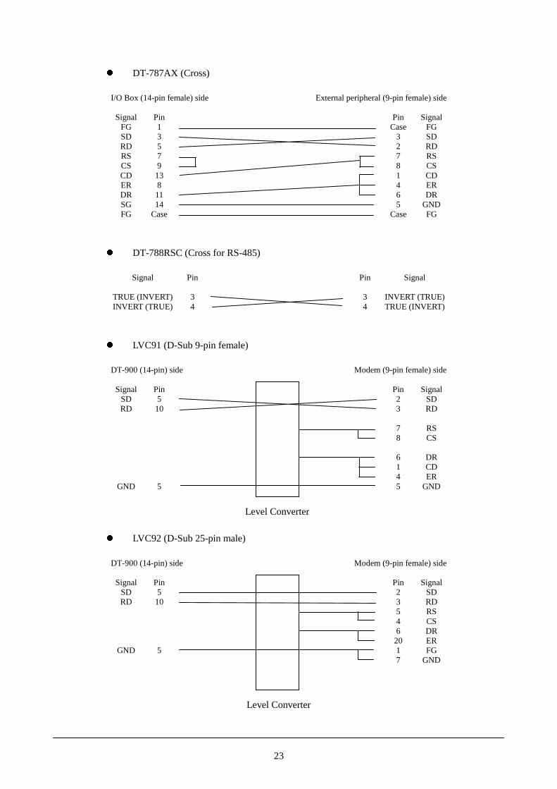
� DT-787AX (Cross)
I/O Box (14-pin female) side External peripheral (9-pin female) side
Signal Pin Pin SignalFG 1 Case FGSD 3 3 SDRD 5 2 RDRS 7 7 RSCS 9 8 CSCD 13 1 CDER 8 4 ERDR 11 6 DRSG 14 5 GNDFG Case Case FG
� DT-788RSC (Cross for RS-485)
Signal Pin Pin Signal
TRUE (INVERT) 3 3 INVERT (TRUE)INVERT (TRUE) 4 4 TRUE (INVERT)
� LVC91 (D-Sub 9-pin female)
DT-900 (14-pin) side Modem (9-pin female) side
Signal Pin Pin SignalSD 5 2 SDRD 10 3 RD
7 RS8 CS
6 DR1 CD4 ER
GND 5 5 GND
� LVC92 (D-Sub 25-pin male)
DT-900 (14-pin) side Modem (9-pin female) side
Signal Pin Pin SignalSD 5 2 SDRD 10 3 RD
5 RS4 CS6 DR20 ER
GND 5 1 FG7 GND
Level Converter
Level Converter

24
10. DT-960IO-E (Basic I/O Box)
10.1 Overview
The DT-960IO-E is a basic I/O box for CASIO DT-900 Data Collection Terminal.This Basic I/O Box facilitates non-contact data transfer between a personal computer and DT-900, and if multiple I/O Boxes are chain-connected, it facilitates connecting multiple DT-900 units to asingle personal computer host. It has an RS-232C interface for connection to personal computer andan optical I/F using CASIO original protocol for connection to a DT-900. Also, it can supply powerto a mounted DT-900.
10.1.1 Features
� Casio-original protocol optical communication with DT-900Employs an optical communication with DT-900.
� Chain links multiple Basic I/O BoxesThe RS-485 driver/receiver is used to connect a maximum of sixteen DT-960IO-Es with a totalline length of 1 Km.
� Power supply capability for DT-900The built-in circuit has a capability of supplying power to the DT-900 preventing the batterypower from being used by the DT-900 during communication.
� Wall-mounting and/or DT-900 tilting capabilitiesThe wall-mounting unit, which was used in the DT-760IO-E, allows the DT-960IO-E to behung on a wall or placed on a desk and tilted as necessary.

25
10.2 External View
���
�������
�� ���
������
�����
�� ���� ������
�� ��� ������
�� ����� ���
�!�" �$%��
%��� �����
�!% �����
%��� �&��'(
��)���'
*�'' )&���+
&��
����+ '�,'�
Fig. 10.1
Note:If tis page is not printed properly, change the printer graphic property from "Vector Graphic" to"Raster Graphic".

26
10.3 Dimensions and Weight
Table 10.1 DimensionsDT-960IO-E Width Deep HeightDesk top shape 110 (W) mm 220 (D) mm 100 (H) mmWall-mouting shape 110 (W) mm 220 (D) mm 110 (H) mmSize of individual carton box 185 (W) mm 115 (D) mm 240 (H) mm
Table 10.2 WeightNet Weight Gross Weight
DT-960IO-E 355 g (approx.) 505 g (approx.)
Notes:1. Net weight : weight of DT-960IO-E only. Gross weight: includes the unit, cartoon box and AC adaptor.2. If the hook and cover for wall mounting are used, the product weight is increased by
approximately 10 g.3. If the nose guide for straight opening is used, the product weight is increased by approximately
5 g.

27
10.4 Block Diagram
��
����
�����
��
���� ����������
������
�� ������
������ ��
���!"!� ��
�� ��
���
�#
�$���%
����%%��
���������
�� ��
&��
'!
������ �� �
�
(�����
)����
)�*�
���
�#
���
�#
)��#)�*�
BASIC I /O Box
Fig. 10.2
Note:The abbreviation “GA” in the above diagram stands for Gate Array.

28
10.5 Specification
10.5.1 General Specification
Table 10.1Block Item Specification Remark
Device UPD65611GBGateArray Operating frequency 7.3728 MHz
Protocol Original Ir Interface (IrDA device) IR comm. onlyby contact.
Synchronization Start/Stop bitMethod Half duplex
Data bit : 8Stop bit : 1
Data format
Parity bit : none
Fixed
Baud rate (bps) 2400, 9600, 19.2K, 38.4K, 57.6K, 115.2KMark : LED offI/F levelSpace: LED on (pulse width 1.6usec.approx)
Pulse width ofON is fixediirespective ofcommunicationspeed.
I/F toDT-900
Usage Connecting DT-900Protocol RS-232CSynchronization Start/Stop bitMethod Half duplex
Data length : 8 bitsStop bit : 1
Data format
Parity bit : noneBaud rate (bps) 2400, 9600, 19.2K, 38.4K, 57.6K, 115.2K
Mark -15 to –5VSDSpace +15 to 5 VMark -3 V or less
I/F level
RDSpace +3 V or more
Pin number and signal
Pin 1 FG Pin 2 Not usedPin 3 SD Pin 4 Not usedPin 5 RD Pin 6 Not usedPin 7 RS Pin 8 ERPin 9 Not used Pin 10 Not usedPin 11 Not used Pin 12 Not used
Connector
Pin 13 CD Pin 14 SG
14-pin female
1) P/C2) Modem
I/F
I/F toHost PC
Usage
3) Printer
������������������������
������������������������

29
�
Block Item Specification RemarkProtocol RS-485 Max. length is
1 Km.Synchronization Start/Stop bitMethod Half duplex
Data bit : 8Stop bit : 1
Data format
Parity bit : none
Fixed
Baud rate (bps) 2400, 9600, 19.2K, 38.4K, 57.6K, 115.2KI/F level ±0.2 to 5V (differential voltage)
6 wired modular connectors
Logic levelMark: highSpace: low
Connector 1 Connector 2
No. 1 INVERT No. 1 TRUE
Connector
No. 2 TRUE No. 2 INVERT
6-pin modularconnector
1) Basic I/O Box
I/F ChainedConnect.I/F
Usage(example)
2) DT-760I/O-E
TR
UE
INV
ER
T
�
IN
VE
RT
TR
UE
�
� � � �
�

30
Block Item Specification RemarkHost PC I/Fbaud ratesetting
Switch 1 2 3
2400 bps OFF OFF OFF9600 bps ON OFF OFF19200 bps OFF ON OFF38.4 Kbps ON ON OFF57.4 Kbps OFF OFF ON115.2 Kbps ON OFF ONProhibited OFF ON ONProhibited ON ON ON
Switch 4 5RS ON -
RS-232CRS/ER signalsON/OFF ER - ON
Switch 6In middle position OFF
Termination
At the end position ONSwitch 7
Yes OFFChainconnection
No ON
No. 8 is notused
DIP switch setting (default at factory)
No. 1 OFF No. 5 OFFNo. 2 ON No. 6 ONNo. 3 OFF No. 7 OFF
DIPswitch
No. 4 OFF No. 8 OFF
Nos. 2 and 6must be set toON.
Power switch Seesaw switch
Switch
DT-900 detection switch Push switchDT-900 is being placed on. RedDT-900DT-900 is not being placed on. Green
2-color LED(Power LED)
Display
Status ofconnection
While communicating OK Green in flashing 2-color LED(green is used)SD LED
Input voltage DC 9.5V �5%Current consumption 300 mA (max.) when power to DT-900Applicable plug type EIAJ RC5320 type 3 Center pin : +
Input AC230V DT-9020ADP-GACadaptor Input AC120V DT-9020ADP-U
Output voltage 5V±10%Output current 300mA
Powersupplyblock Excess current
ProtectionDrop-type excess current protection circuit(600mA or more)GND -Power supply +XIRCNT RNot used C
Powersupply
Terminalblock
Layoutf of terminals
GN
D
Po
wer
Su
pply
Term
inal
XIR
CN
T
No
t use
d
�������
�����
����
� � � � � �
�
� � � �

31
10.5.2 Electric Specification
Table 10.2Item Specification Remark
Power consumption 2.7 W When Casio adaptor is used.Input voltage DC 9.5 V ±5% “EIAJ RC5320 type 3” plug
DT-9020ADP-G AC220-240V 50/60HzAC adaptorDT-9020ADP-U AC100-120V 50/60Hz
Input conditions:Voltage:±10% of rated voltageFrequency:±1Hz of rated frequency
Line noise Malfunction at 700V Pulse width: 100 to 800 nsec.Cycle:10 to 35 msec. (variable)Polarity: +, -
Instantaneous powerline off
Malfunction at 10 msec. or less
DT-9020ADP-G AC1500V for 1 min.Insulation voltageDT-9020ADP-U AC1000V for 1 min.DT-9020ADP-G 50Mohm at DC500VInsulation resistanceDT-9020ADP-U 50Mohm at DC500VDT-9020ADP-G 3.5 mA or lessLeak currentDT-9020ADP-U 1.0 mA or less
Tested with DT-9020ADP-Gand DT-9020ADP-U
Terminal noisevoltage
In compliance with EN55022 Tested with DT-9020ADP-G
Noise radiationelectric field
In compliance with EN55022 Tested with DT-9020ADP-G
10.5.3 Environmental Specification
Table 10.3Item Specification Remark
Operation 0� to 40�TemperatureStorage -10� �� ���
Operation 30% to 80%RHHumidityStorage 30% to 90%RH
at 40�. No condensation
Malfunction at 5 KVElectrostaticDestruction at 10 KV
Conditions:Equavalent human body resistance: 100 ohmEquavalent human body capacity: 250 pFFrequency of application : 10 timesPeriod of application : 0.3/0.3 sec.

32
10.5.4 Mechanical Strength
Table 10.4Item Specification Remark
Height 30 cm or lessShock-proofDirection 6 faces
Local impact 1 Kg at specified positionsOverall impact 20 KgResistance to vibration 0.15 G Conditions:
In X,Y, Z directions10 to 55 Hz30 minutes
10.6 Transport and Storage
10.6.1 Transport (packaging)
Table 10.5�� � ��������� �����
Temperature -10� to 50�Humidity 30% to 90%RH Conditions:
40� No condensationDirection of fall Once for each of the six faces,
one corner, and three edgesShock-proof
Height of fall 70 cm or less(with individual carton box)
Resistanceto vibration
1.5 G or less Conditions:In the X, Y, Z directions15 minutes
Notes:1. If the packing material is found to be damaged when the equipment is re-packed, replace the
damaged material before transport.2. When handling the package, observe the handling instructions on the package.
10.6.2 Storage
Table 10.6Item Specification Remark
Temperature -10� to 50�Humidity 30 to 90%RH at 40� No condensationStorage period 12 months or lessPackage condition 1) Do not tilt.
2) If stacking, observe the handling instructions on the package.3) Avoid placing in direct sunlight.4) Do not expose to inclement weather.
33
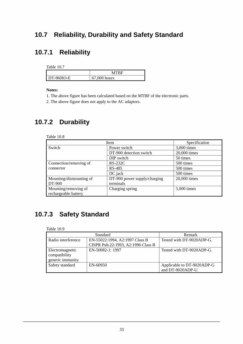
10.7 Reliability, Durability and Safety Standard
10.7.1 Reliability
Table 10.7MTBF
DT-960IO-E 67,000 hours
Notes:1. The above figure has been calculated based on the MTBF of the electronic parts.2. The above figure does not apply to the AC adaptors.
10.7.2 Durability
Table 10.8Item Specification
Power switch 3,000 timesDT-900 detection switch 20,000 times
Switch
DIP switch 50 timesRS-232C 500 timesRS-485 500 times
Connection/removing ofconnector
DC jack 500 timesMounting/dismounting ofDT-900
DT-900 power supply/chargingterminals
20,000 times
Mounting/removing ofrechargeable battery
Charging spring 5,000 times
10.7.3 Safety Standard
Table 10.9Standard Remark
Radio interference EN-55022:1994, A2:1997 Class BCISPR Pub.22:1993, A2:1996 Class B
Tested with DT-9020ADP-G.
Electromagneticcompatibilitygeneric immunity
EN-50082-1: 1997 Tested with DT-9020ADP-G.
Safety standard EN-60950 Applicable to DT-9020ADP-Gand DT-9020ADP-U.
34
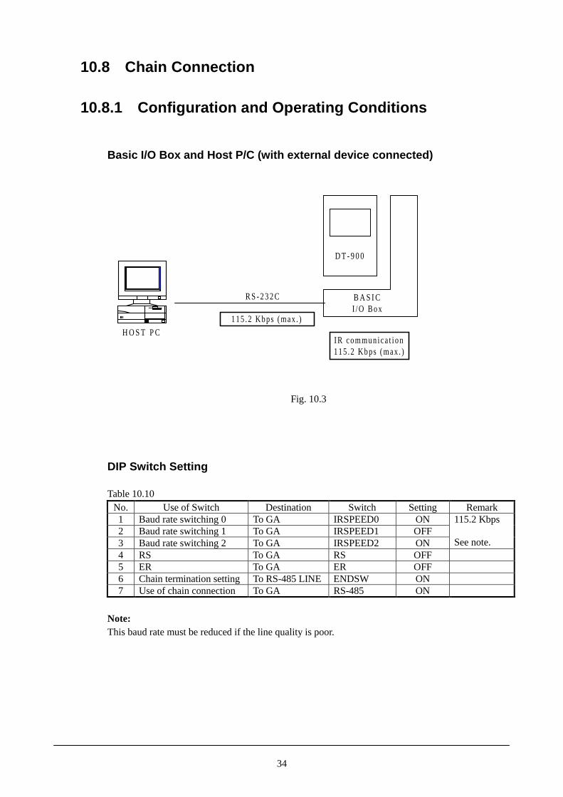
10.8 Chain Connection
10.8.1 Configuration and Operating Conditions
Basic I/O Box and Host P/C (with external device connected)
H O S T P C
D T - 9 0 0
B A S I CI /O Box
R S - 2 3 2 C
IR commun ica t ion115 .2 Kbps (max . )
115 .2 Kbps (max . )
Fig. 10.3
DIP Switch Setting
Table 10.10No. Use of Switch Destination Switch Setting Remark1 Baud rate switching 0 To GA IRSPEED0 ON2 Baud rate switching 1 To GA IRSPEED1 OFF3 Baud rate switching 2 To GA IRSPEED2 ON
115.2 Kbps
See note.4 RS To GA RS OFF5 ER To GA ER OFF6 Chain termination setting To RS-485 LINE ENDSW ON7 Use of chain connection To GA RS-485 ON
Note:This baud rate must be reduced if the line quality is poor.

35
Basic I/O Boxes and Host P/C
H O S T P CD T - 9 0 0
Bas ic I /O Box
�S - 2 3 2 Ccable
R S - 4 8 5Modu lar cab le
R S - 4 8 5Modu lar cab le
RS-232C connc t .
IR coom.115 Kbps (max . )
Bas ic I /O Box Bas ic I /O Box
D T - 9 0 0 D T - 9 0 0
Termina t ion at midd le Termina t ion
115 Kbps (max . )
IR comm.��� ���� ���
IR comm.115 Kbps (max . )
H O S T P CD T - 9 0 0
Bas ic I /O Box
R S - 2 3 2 Ccable
RS-485 Modu la r cab le
R S - 4 8 5Modu lar cab le
RS-232C connc t .
IR comm.115 Kbps (max . )
Bas ic I /O Box Bas ic I /O Box
D T - 9 0 0 D T - 9 0 0
Termina t ion At midd le Termina t ion
115 Kbps (max . )
IR comm.115 Kbps (max . )
IR comm.115 Kbps (max . )
Conf igura t ion Example A
Conf igura t ion Example B
Fig. 10.4DIP Switch Setting
Table 10.11SettingNo. Use of Switch Destination Switch
RS-232Cconnection
Middle ofchain
End ofchain
Remark
1 Baud rate switching 0 To GA IRSPEED0 ON ON ON2 Baud rate switching 1 To GA IRSPEED1 OFF OFF OFF3 Baud rate switching 2 To GA IRSPEED2 ON ON ON
115.2Kbps
Seenote.
4 RS To GA RS OFF OFF OFF5 ER To GA ER OFF OFF OFF6 Chain termination
settingTo RS-485 LINE
ENDSW - OFF ON
7 Use of chainconnection
To GA RS-485 OFF OFF OFF
Note:This baud rate must be reduced if the line quality is poor.

36
Multiple Basic I/O Boxes
D T - 9 0 0
Bas ic I /O Box
R S - 4 8 5Modu la r cab le
IR comm.115Kbps (max . )
Bas ic I /O Box Bas ic I /O Box
D T - 9 0 0 D T - 9 0 0
Termina t ion At midd le Termina t ion
IR comm.115Kbps (max . )
IR comm.115Kbps (max . )
R S - 4 8 5Modu la r cab le
Fig. 10.5
DIP Switch Setting
Table 10.12SettingNo. Use of Switch Destination Switch
Middleof chain
End ofchain
Remark
1 Baud rate switching 0 To GA IRSPEED0 ON ON2 Baud rate switching 1 To GA IRSPEED1 OFF OFF3 Baud rate switching 2 To GA IRSPEED2 ON ON
115.2 Kbps
See note.4 RS To GA RS OFF OFF5 ER To GA ER OFF OFF6 Chain termination
settingTo RS-485 LINE ENDSW OFF ON
7 Use of chainconnection
To GA RS-485 OFF OFF
Note:This baud rate must be reduced if the line quality is poor.

37
10.8.2 Cable Specification
Cable for Chain Connection (short distance)A cable for the chain connection within distance of 1 meter or less (between DT-960IO-E andDT-960IO-E) is available as option. The model name of the cable is DT-788RSC(cable length: 1 m).
View from side
View from above
� � � � � �
Max. 1 m
Modular plug6/6-6 FR SYK
� � � � � �
Cable (see Table 10.13)
Fig. 10.6Table 10.13
CableConductive 20/0.1 AInsulation Semi-rigid P.V.C
Core wire
Finish form 20/0.1 AInsulation P.V.CSheathFinish O.D. �4.3 �0.1 mmConductive resistance 0.12 ohm/m or lessCharacteristicsInsulation resistance 50 Mohm or greater
Wiring of the cable (cross cable)
I/O Box at downstream side I/O Box at upperstream sidePin no. Signal Pin no. Signal
1 12 23 TRUE 3 INVERT4 INVERT 4 TRUE5 56 6

38
Cable for Chain Connection (long distance)
View f rom s ide
V iew f rom above
� � � � � �
Max . 1 ,000 m
Modu la r p lug6 / 6 - 6 F R S Y K
� � � � � �
Cab leS K - U T P 1 0 0 M 3 P
Fig. 10.7
Wiring of the cable (cross and twist pair)
I/O Box at downstream side I/O Box at upperstream sidePin no. Signal Pin no. Signal
1 12 23 TRUE 3 INVERT4 INVERT 4 TRUE5 56 6
������������

39
10.8.3 Notes About Chain Connection
Cable layoutTake the followings into consideration when routing the cables from each I/O Box:� Compression, extension, bending due to heavy load� Attachment to a movable part� Routing over a sharp edge� Routing near a strong electric field
Note:Improper routing of a cable may cause a cable fault or a short circuit, damaging propercommunication.
Do not route cables near precision equipment (measuring equipment, etc.), a radio or televisionreceiver, or wireless equipment. If cables are routed near such a piece of equipment, it may besubject to electrical interference.
Precautions to be observed when manufacturing cables� If the CASIO cables cannot be used, and custom-made cables are required instead, use the
manufacturer-specified cramping tool to cramp the modular connector and cable.Note:Defective cramping may damage communication.
� Cables for Basic I/O Box are designed for cross-type connection. Note that the number ofcore wires and connection method are different from those for Satellite I/O Box.

40
11. DT-964IO-E (Satellite I/O Box)
11.1 Overview
The DT-964IO-E (Satellite I/O Box) is an I/O box specifically for DT-900 data collection terminal.This Satellite I/O Box facilitates non-contact data transfer between a PC and a DT-900, and, ifmultiple I/O Boxes are chain-connected, it facilitates connecting multiple DT-900 units to a singleHost PC. It has an RS-232C interface for connection to a PC and an IrDA interface for connection toa DT-900. Also, it can supply power to a mounted DT-900.
11.1.1 Features
� IrDA Ver. 1.2 optical communication with DT-900Employs IrDA Ver. 1.2 for optical communication with DT-900.
� Chain links multiple Satellite I/O BoxesThe RS-422 driver/receiver is used to connect a maximum of eight units of DT-964IO-E with atotal cable length of 1 Km.
� Power supply capability for DT-900The circuit has a capability of supplying power to the DT-900, preventing the rechargingelectric energy from being used by the DT-900.
� Battery recharging capabilityThis I/O Box can recharge the battery being installed in DT-900 or can recharge a battery alone.Five hours is required to fully recharge the battery in the charging compartment.
� Wall-mounting and/or DT-900 tilting capabilitiesThe wall-mounting unit, which was used in the DT-964IO-E, allows the DT-964IO-E to behung on a wall or placed on a desk and tilted as necessary.

41
11.2 External View
LED pane l
D T - 9 0 0
detect ion
swi tch
RS-232C connec to rRS-422 connector (C- IN s ide)
AC adaptor jack
E I A J T Y P E 4
Wal l -mount ing un i t
D IP sw i tch
RS-422 connec to r (C-OUT s ide)
Charg ing /
power supp ly
terminal
L i th ium-Ion bat tery pack charg ing compar tment
Rat ing label
Fig. 11.1
Note:If tis page is not printed properly, change the printer graphic property from "Vector Graphic" to"Raster Graphic".

42
11.3 Dimensions and Weight
Table 11.1 DimensionsDT-964IO-E Width Depth Height
Desktop type 110 mm 220 mm 100 mmWall-mounting type 110 mm 220 mm 110 mmIndividual carton box 185 mm 115 mm 240 mm
Table 11.2 WeightSelf In carton box
DT-964IO-E 500 g (approx.) 750 g (approx.)
Notes:1. Net weight : weight of DT-964IO-E only. Gross weight: includes the unit, cartoon box and AC adaptor.2. If the hook and cover for wall mounting are used, the product weight is increased by
approximately 10 g.3. If the nose guide for straight opening is used, the product weight is increased by approximately
5 g.

43
11.4 Block Diagram
I r D AM O D E M
B R G
P o w e r M a n a g e m e n t
Cha rge Modu le
D T -900
AC adap to r
S H 7 0 2 0
S R A M
E P R O M
3 2 K B ( 2 5 6 K b )
1 2 8 K B ( 1 M b )
RS-422 I /F
RS-232C I /F
I rDA I /F
M o d eContro l ler
D IP sw i tch
SignalContro l ler
Gate Arra y
3 6 . 8 6 4 M H z
I rDAI /F
Satel l i te I /O Box
S R A M
1 K B ( 8 K b )
Bui l t - in
L E D
x4
1 8 . 4 3 2 M H z
S R A M
����������
M A S KR O M
1 2 8 K B ( 1 M b )
Fig. 11.2

44
11.5 Specification
11.5.1 Genera l Specification
Table 11.3Block Item Specification Remark
Device SH7020 By HITACHINo. of bits 32 bits RISC
GateArray
Operating frequency 18.432 MHz Built-inMASKROMis not used.
Device SRM2B256SLMX-70 2 pcs (16-bit)Capacity 32 Kbytes
SRAM
Access time 70 nsec.Device M27C1024-10L1 Erasable with
ultra-violetlight
Capacity 128 Kbytes
Memory
EEPROM(MASKROM)
Access time 100 nsec.Use the ICsocket toupdate thefi rmware.
Protocol Original Ir Interface (IrDA device)Conforms toVer. 1.2
By contactmethod only.
Synchronization Start/Stop bitMethod Half duplex
Data bit : 8Stop bit : 1
Data format
Parity bit : none
Fixed
Baud rate (bps) 9600, 38.4K, 115.2 K Bitswitch/settingof IrCOMM
Mark : LED offI/F levelSpace: LED on (pulse width 1.6 usec.approx.)
On-pulse widthis fixedirrespective ofthe ransmissionrate.
I/F toDT-900
Usage Connecting DT-900Protocol RS-232CSynchronization Start/Stop bitMethod Full duplex/Half duplex
Data length : 8 bitsStop bit : 1
Data format
Parity bit : none
Bitswitch/settingof IrCOMM
Baud rate (bps) 2400, 4800, 9600, 19.2K, 38.4K, 57.6K, 115.2KMark -15 to –5VSDSpace +15 to 5 VMark -3 V or less
I/F level
RDSpace +3 V or more
5 4 3 2 1
9 8 7 6
DSUB 9 pin (male)Pin no. 1 CD Pin no. 2 RDPin no. 3 SD Pin no. 4 ERPin no. 5 SG Pin no. 6 DPin no. 7 RS Pin no. 8 CS
Connector(example)
Pin no. 9 CI
D-sub 9-pin(male)connector
I/F
I/F toHost PC
Usage(example)
1) P/C2) Modem3) Printer
�� �� �� �� ��
�� �� �� �

45
Block Item Specification RemarkProtocol RS-422 Max. length 1
KmSynchronization Start/Stop bit Same
specificationas I/F to DT-900.
Method Half duplexData bit : 8Stop bit : 1
Data format
Parity bit : none
Fixed
Baud rate (bps) 9600, 38.4K, 115.2K Bitswitch/Settingof IrCOMM
I/F level ±2 to 5 V (differential voltage) Logic levelMark: highSpace: low
6 wired-modular connector
OUT IN
No. 1 RSO+ No. 1 RSI+No. 2 RSO- No. 2 RSI-No. 3 SDO+ No. 3 SDI+No. 4 SDO- No. 4 SDI-No. 5 RDI+ No. 5 RDO+
Connector
No. 6 RDI- No. 6 RDO-
6-wiremodularconnector
ChainI/F
Usage(example)
1) Basic I/O Box2) Master I/O Box
Table 11.3 continues to the next page.
� � � � � �
OUTR
DI-
RD
I+
SD
O-
SD
O+
RS
O-
RS
O+
RD
O-
RD
O+
SD
I-
SD
I+
RS
I-
RS
I+
IN
� � � � � �
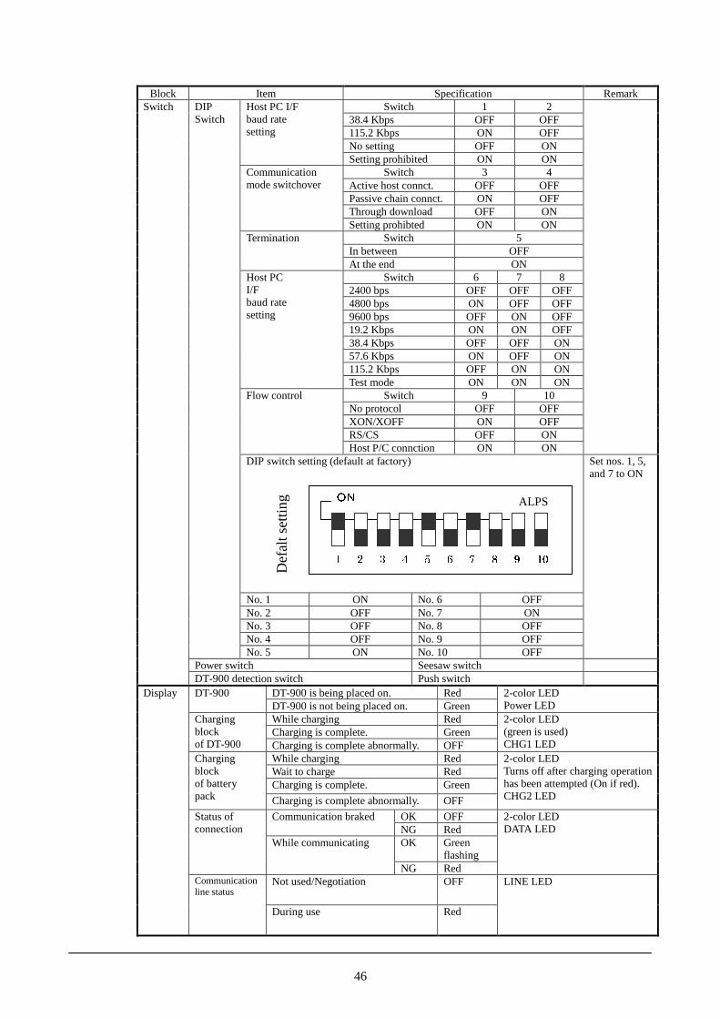
46
Block Item Specification RemarkSwitch 1 2
38.4 Kbps OFF OFF115.2 Kbps ON OFFNo setting OFF ON
Host PC I/Fbaud ratesetting
Setting prohibited ON ONSwitch 3 4
Active host connct. OFF OFFPassive chain connct. ON OFFThrough download OFF ON
Communicationmode switchover
Setting prohibted ON ONSwitch 5
In between OFFTermination
At the end ONSwitch 6 7 8
2400 bps OFF OFF OFF4800 bps ON OFF OFF9600 bps OFF ON OFF19.2 Kbps ON ON OFF38.4 Kbps OFF OFF ON57.6 Kbps ON OFF ON115.2 Kbps OFF ON ON
Host PCI/Fbaud ratesetting
Test mode ON ON ONSwitch 9 10
No protocol OFF OFFXON/XOFF ON OFFRS/CS OFF ON
Flow control
Host P/C connction ON ONDIP switch setting (default at factory)
No. 1 ON No. 6 OFFNo. 2 OFF No. 7 ONNo. 3 OFF No. 8 OFFNo. 4 OFF No. 9 OFF
DIPSwitch
No. 5 ON No. 10 OFF
Set nos. 1, 5,and 7 to ON
Power switch Seesaw switch
Switch
DT-900 detection switch Push switchDT-900 is being placed on. RedDT-900DT-900 is not being placed on. Green
2-color LEDPower LED
While charging RedCharging is complete. Green
Chargingblockof DT-900 Charging is complete abnormally. OFF
2-color LED(green is used)CHG1 LED
While charging RedWait to charge RedCharging is complete. Green
Chargingblockof batterypack Charging is complete abnormally. OFF
2-color LEDTurns off after charging operationhas been attempted (On if red).CHG2 LED
OK OFFCommunication brakedNG RedOK Green
flashing
Status ofconnection
While communicating
NG Red
2-color LEDDATA LED
Not used/Negotiation OFF
Display
Communicationline status
During use Red
LINE LED
�� ALPS
Def
alt s
ettin
g
� � � � � � � � � ��

47
Block Item Specification RemarkInput voltage DC12V±5%
Power consumption 600 mA (max.) (120 mA if notcharging)
While charging DT-900
Applicable plug EIAJ RC5320 type 4 Center pin : positive
DT-825ADP-G (230VAC)Applicable AC adaptor
DT-825ADP-U (120VAC)
Specifications BC-9801C
Input voltage 6.5 to 15V
Power consumption 5 VA or less
DT-923LI
Nominal voltage 3.6 V
Objective battery
Nominal capacity 600 mA
Chargingspecification
Output voltage 4.1V±50 mV
During charging 300±30 mA (3.0 V <Battery voltage �4.1 V)During charging 30±12 mA (2.6 V <Battery voltage �3.0 V)
Output current
In the check mode 300±30 mA
Current to check ifcharging is complete
30±12 mA
Voltage to check ifrecharging iscomplete
3.9±0.1 V
Voltage to checkbattery anomaly
2.6V±0.1 V
Dark current 4.3 µA
Chargingmodule
Charging time 5 hours At room temperature
Output voltage 5 V±10%
Output current 300 mA
Powersupplyblock Excess current
protectionDrop type excess currentprotection circuit(600 mA or greater)
Connector AXZ99002009 (by MatsushitaElectric Works)
2 pcs
GND -Power supply terminal +
Not used R
Powersupply
Terminalblock
Layout of terminals
Chaging terminal C
GN
D
No
t us
ed
Po
we
r su
pp
ly
term
inal
Cha
rgin
g
term
inal
� � � �

48
11.5.2 Electric Specification
Table 11.4Item Specification Remark
Power consumption 7.2 W With applicable AC adaptorAvailable power supply DC 12V±5% With EIAJ RC5320 type 4 plug
DT-825ADP-G Input rating: AC 220 to 240V, 50/60 HzDT-825ADP-U Input rating: AC 100 to 120V, 50/60 Hz
Input conditions:Voltage: 10% of rated input voltageFrequency: ±1 Hz of rated inputfrequency
Line noise strength Malfunction at 700 V Pulse width : 100 to 800 nsec.Frequency : 10 to 35 msec. (variable)Polarity : +, -
Instantaneous power line off Malfunction after 10 msec. or lessDT-825ADP-U AC1000V for 1 min.Insulation voltageDT-825ADP-G AC1500V for 1 min.DT-825ADP-U 50 Mohm at DC500VInsulation resistanceDT-825ADP-G 50 Mohm at DC500VDT-825ADP-U 1 mA or lessLeak currentDT-825ADP-G 3.5 mA or less
Terminal noise voltage Conform to EN55022Noise radiation electric field Conform to EN55022
11.5.3 Environment Specification
Table 11.5Item Specification Remark
Operation 0� to 40�Temperature
Storage -10� to 50�Operation 30% to 80%RHHumidityStorage 30% to 90%RH
At 40�. No condensation.
Malfunction at 5 KVElectrostaticDestruction at 10 KV
Conditions:Equivalent human body resistance: 100 ohmEquivalent human body capacity: 250 pFFrequency of application: 10 timesPeriod of application: 0.3/0.3 sec.
11.5.4 Mechanical Strength
Table 11.6Item Specification Remark
Height of fall 30 cm or lessShock-proofDirection 6 faces at specified faces
Local impact 1 Kg at specified positionOverall impact 20 KgResistance tovibration
0.15 G Conditions:in X, Y, Z directions10 and 55 Hz30 minutes
49
11.6 Transport and Storage
11.6.1 Transport (packaging)
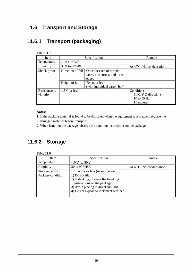
Table 11.7Item Specification Remark
Temperature -10� to 50�Humidity 30% to 90%RH At 40�. No condensation.
Direction of fall Once for each of the sixfaces, one corner, and threeedges
Shock-proof
Height of fall 70 cm or less(with individual carton box)
Resistance tovibration
1.5 G or less Conditions:In X, Y, Z directions10 to 55 Hz15 minutes
Notes:1. If the packing material is found to be damaged when the equipment is re-packed, replace the damaged material before transport.2. When handling the package, observe the handling instructions on the package.
11.6.2 Storage
Table 11.8Item Specification Remark
Temperature -10� to 50�Humidity 30 to 90 %RH At 40�. No condensation.Storage period 12 months or less (recommended)Package condition 1) Do not tilt.
2) If stacking, observe the handling instructions on the package.3) Avoid placing in direct sunlight.4) Do not expose to inclement weather.

50
11.7 Reliability, Durability and Safety Standard
11.7.1 Reliability
Table 11.9Model MTBF
DT-964IO-E 48,000 hours
Notes:1. The above figure has been calculated based on the MTBF of the electronic parts.2. The above figure does not apply to the AC adaptors.
11.7.2 Durability
Table 11.10Item SpecificationPower switch 3,000 timesDT-900 detection switch 20,000 times
Switch
DIP switch 50 timesRS-232C 500 timesRS-422 500 times
Connection/removing ofconnector
DC jack 500 timesMounting/dismounting ofDT-900
DT-900 power supply/chargingterminals
20,000 times
Mounting/removing ofrechargeable battery
Charging spring 5,000 times
11.7.3 Safety Standard
Table 11.11Standard Remark
Radio interference EN-55022:1994, A2:1997 Class BCISPR Pub.22:1993, A2:1996 Class B
Tested with DT-825ADP-G.
Electromagneticcompatibilitygeneric immunity
EN-50082-1: 1997 Tested with DT-825ADP-G.
Safety standard EN-60950 Applicable only to DT-825ADP-G and DT-825ADP-U
51
11.8 Chain Connection
11.8.1 Configuration and Operating Conditions
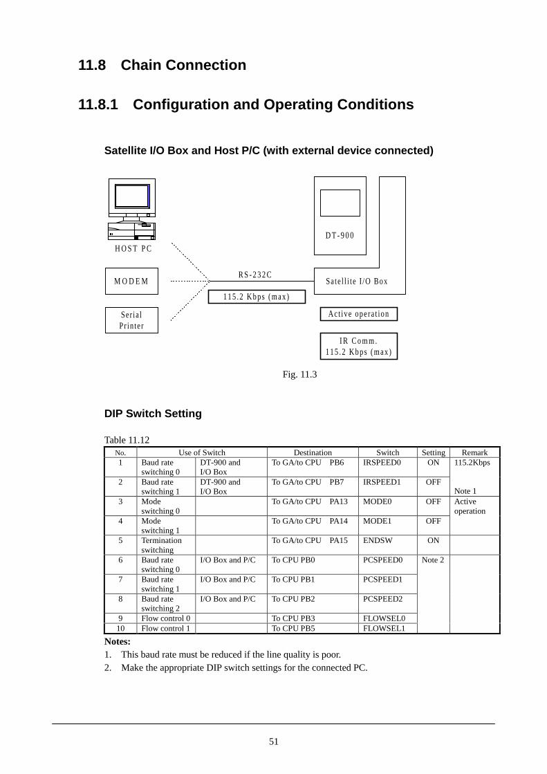
Satellite I/O Box and Host P/C (with external device connected)
H O S T P C
M O D E M
Ser ia lPr in ter
D T - 9 0 0
Sate l l i te I /O BoxR S - 2 3 2 C
Act ive opera t ion
I R C o m m .115 .2 Kbps (max)
115 .2 Kbps (max)
Fig. 11.3
DIP Switch Setting
Table 11.12No. Use of Switch Destination Switch Setting Remark1 Baud rate
switching 0DT-900 andI/O Box
To GA/to CPU PB6 IRSPEED0 ON
2 Baud rateswitching 1
DT-900 andI/O Box
To GA/to CPU PB7 IRSPEED1 OFF
115.2Kbps
Note 13 Mode
switching 0To GA/to CPU PA13 MODE0 OFF
4 Modeswitching 1
To GA/to CPU PA14 MODE1 OFF
Activeoperation
5 Terminationswitching
To GA/to CPU PA15 ENDSW ON
6 Baud rateswitching 0
I/O Box and P/C To CPU PB0 PCSPEED0
7 Baud rateswitching 1
I/O Box and P/C To CPU PB1 PCSPEED1
8 Baud rateswitching 2
I/O Box and P/C To CPU PB2 PCSPEED2
9 Flow control 0 To CPU PB3 FLOWSEL010 Flow control 1 To CPU PB5 FLOWSEL1
Note 2
Notes:1. This baud rate must be reduced if the line quality is poor.2. Make the appropriate DIP switch settings for the connected PC.

52
Master I/O Box, Satellite I/O Box and Host P/C
H O S T P C
DT-900
Master I /O BoxConnect ing
route
DT-900
Satel l i te I /O Box
DT-900
RS-422
Modu la r cab lePassive operat ion
RS-422
Modu la r cab lePassive operat ion
IR comm.115 Kbps
Satel l i te I /O Box
IR comm.115 Kbps
IR comm.115 Kbps
Fig. 11.4
DIP Switch Setting
Table 11.13SettingNo. Use of Switch Destination Switch
Inmiddle
At endRemark
1 Baud rateswitching 0
DT-900 andI/O Box
To GA/to CPU PB6 IRSPEED0 ON ON
2 Baud rateswitching 1
DT-900 andI/O Box
To GA/to CPU PB7 IRSPEED1 OFF OFF
115.2Kbps
Note 1
3 Modeswitching 0
To GA/to CPU PA13 MODE0 ON ON
4 Modeswitching 1
To GA/to CPU PA14 MODE1 OFF OFF
PassiveOperation
5 Terminationswitching
To GA/to CPU PA15 ENDSW OFF ON
6 Baud rateswitching 0
I/O Box andP/C
To CPU PB0 PCSPEED0
7 Baud rateswitching 1
I/O Box andP/C
To CPU PB1 PCSPEED1
8 Baud rateswitching 2
I/O Box andP/C
To CPU PB2 PCSPEED2
9 Flow control 0 To CPU PB3 FLOWSEL010 Flow control 1 To CPU PB5 FLOWSEL1
Do not care Note 2
Notes:1. This baud rate must be reduced if the line quality is poor.2. This setting is invalid during passive operation.

53
Multiple Satellite I/O Boxes and Host P/C
H O S T P C
DT-900
Satel l i te I /O BoxRS-232C
R S-422Modular cable
RS-422Modular cable
Passive operat ionPassive operat ion
IR comm.115.2 Kbps (max)
Act ive operat ion
IR comm.115.2 Kbps (max)
IR comm.115.2 Kbps (max)
115.2 Kbps (max)
DT-900DT-900
Satel l i te I /O Box Satel l i te I /O Box
Fig. 11.5
DIP Switch Setting
Table 11.14Setting
Active PassiveNo. Use of Switch Destination Switch
Inmiddle
At end
Remark
1 Baud rateswitching 0
DT-900 andI/O Box
To GA/to CPU PB6 IRSPEED0 ON ON ON
2 Baud rateswitching 1
DT-900 andI/O Box
To GA/to CPU PB7 IRSPEED1 OFF OFF OFF
115.2Kbps
Note 1
3 Mode switching0
To GA/to CPU PA13 MODE0 OFF ON ON
4 Mode switching1
To GA/to CPU PA14 MODE1 ON OFF OFF
5 Terminationswitching
To GA/to CPU PA15 ENDSW OFF OFF ON
6 Baud rateswitching 0
I/O Box andP/C
To CPU PB0 PCSPEED0
7 Baud rateswitching 1
I/O Box andP/C
To CPU PB1 PCSPEED1
8 Baud rateswitching 2
I/O Box andP/C
To CPU PB2 PCSPEED2
9 Flow control 0 To CPU PB3 FLOWSEL010 Flow control 1 To CPU PB5 FLOWSEL1
Note 2 Do not care.
Notes:1. This baud rate must be reduced if the line quality is poor.2. Make the appropriate DIP switch settings for the connected PC.

54
For Downloading
H O S T P C
DT-900
Satel l i te I /O BoxRS-232C
DT-900
Satel l i te I /O Box
DT-900
RS-422Modular cable
RS-422Modular cable
Passive operat ionPassive operat ion
IR comm.115.2 Kbps (max)
Through operat ion
IR comm.115.2 Kbps (max)
IR comm.115.2 Kbps (max)
115.2 Kbps (max)
Satel l i te I /O Box
Fig. 11.6
DIP Switch Setting
Table 11.15Setting
PassiveNo. Use of Switch Destination Switch
ThroughIn
middleAt end
Remark
1 Baud rateswitching 0
DT-900 andI/O Box
To GA/to CPUPB6
IRSPEED0 ON ON ON
2 Baud rateswitching 1
DT-900 andI/O Box
To GA/to CPUPB7
IRSPEED1 OFF OFF OFF
115.2Kbps
Note 13 Mode switching 0 To GA/to CPU
PA13MODE0 OFF ON ON
4 Mode switching 1 To GA/to CPUPA14
MODE1 ON OFF OFF
5 Terminationswitching
To GA/to CPUPA15
ENDSW OFFNote 4
OFF ON
6 Baud rateswitching 0
I/O Box andP/C
To CPU PB0 PCSPEED0
7 Baud rateswitching 1
I/O Box andP/C
To CPU PB1 PCSPEED1
8 Baud rateswitching 2
I/O Box andP/C
To CPU PB2 PCSPEED2
9 Flow control 0 To CPU PB3 FLOWSEL0
10 Flow control 1 To CPU PB5 FLOWSEL1
Note 3 Do not care.
Note 2
Notes:1. This baud rate must be reduced if the line quality is poor.2. Make the appropriate DIP switch settings for the connected PC.3. This setting is invalid during the passive operation.4. Set to ON if only one I/O Box is used.

55
11.8.2 Cable Specification
Cable for Short Distance (1 m or less)
View f rom s ide
V iew f rom above
� � � � � �
Max . 1 m
Modu la r p lug6 /6 -6 FR SYK
� � � � � �
Cable (see Tab le 11 .16)
Fig. 11.7
Table 11.16Cable
Conductive 20/0.1 AInsulation Semi-rigid P.V.C
Core wire
Finish form 20/0.1 AInsulation P.V.CSheathFinish O.D. �4.3�0.1 mmConductive resistance 0.12 ohm/m or lessCharacteristicsInsulation resistance 50 Mohm or greater
Wiring of the cable (streight connection, pin-to-pin)
I/O Box at downstream side I/O Box at upperstream sidePin no. Signal Pin no. Signal
1 IRS+ 1 ORS+2 IRS- 2 ORS-3 ISD+ 3 OSD+4 ISD- 4 OSD-5 ORD+ 5 IRD+6 ORD- 6 IRD-

56
Cable for Chain Connection
View f rom s ide
V iew f rom above
� � � � � �
Max . 1 ,000 m
Modu la r p lug6 / 6 - 6 F R S Y K 5 0
� � � � � �
Cab leS K - U T P 1 0 0 M 3 P
Fig. 11.8
Wiring of the cable (streight connection, pin-to-pin)
I/O Box at downstream side I/O Box at upperstream sidePin no. Signal Pin no. Signal
1 IRS+ 1 ORS+2 IRS- 2 ORS-3 ISD+ 3 OSD+4 ISD- 4 OSD-5 ORD+ 5 IRD+6 ORD- 6 IRD-
XXXXXXXXXXXXXXXXX
XXXXXXXXXXXXXXXX
XXXXXXXXXXXXXXXXX

57
11.8.3 Precautions
Cable LayoutTake the following into consideration when routing the cables leading from each I/O Box:� Compression, extension, bending due to heavy load� Attachment to a movable part� Routing over a sharp edge� Routing near a strong electric field
Note:Improper routing of a cable may cause a cable fault or a short circuit, damaging propercommunication.
Do not route cables near precision equipment (measuring equipment, etc.), a radio or televisionreceiver, or wireless equipment. If cables are routed near such a piece of equipment, it may besubject to electrical interference.
Precautions to be observed when manufacturing cables� If CASIO cables cannot be used, and custom-made cables are required, use the manufacturer-
specified cramping tool to cramp the modular connector and cable.Note:Defective cramping may damage communication.

58
12. DT-969CHG-E (I/O Box Type Recharger)
12.1 Overview
The DT-969CHG-E (I/O Box-type/contact-type recharge unit) is a charging box for DT-900 datacollection terminal. It has the charging and power supply functions for DT-900, as well as there-charging function for a spare battery pack of DT-900.
12.1.1 Features
� Recharging and power supply function for DT-900It has incorporated a charging circuit for the main battery of the DT-900.Five hours is required to fully charge the battery. The circuit has a capability of supplyingpower to the DT-900, preventing the recharging electric energy from being used by the DT-900.
� Recharging function for spare battery packIt has the recharging function for a spare battery pack, DT-923LI, without installing it in theDT-900.
� Wall-mounting and/or DT-900 tilting capabilitiesThe wall-mounting unit, which was adopted in the DT-760IO-E, allows the DT-969CHG-E tobe hung on a wall or placed on a desk and tilted as necessary.
59
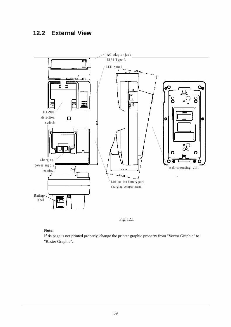
12.2 External View
LED pane l
D T - 9 0 0
detect ion
swi tch
AC adaptor jack
EIAJ Type 3
Wal l -mount ing un i t
Charg ing/
power supp ly
terminal
L i th ium-Ion bat tery pack
charg ing compar tment
Rat inglabel
Fig. 12.1
Note:If tis page is not printed properly, change the printer graphic property from "Vector Graphic" to"Raster Graphic".

60
12.3 Dimensions and Weight
Table 12.1 DimensionsDT-969CHG-E Width Depth Height
Desktop type 110 mm 220 mm 100 mmWall-mounting type 110 mm 220 mm 110 mmIndividual carton box 185 mm 115 mm 240 mm
Table 12.2 WeightSelf In carton box
DT-969CHG-E 390 g (approx.) 640 g (approx.)
Notes:1. Net weight : weight of DT-969CHG-E only. Gross weight: includes the unit, cartoon box and AC adaptor.2. If the hook and cover for wall mounting are used, the product weight is increased by
approximately 10 g.3. If the nose guide for straight opening is used, the product weight is increased by approximately
5 g.
12.4 Block Diagram
P o w e r M a n a g e m e n t
D T - 9 0 0
AC adap to r
H T A D P
H T O NH T S W
ChargeM o d u l e
Fig. 12.2

61
12.5 Specification
12.5.1 General SpecificationTable 12.1
Item Specification RemarkPower switch Seesaw switchDT-900 detection switch Push switch
When not loading DT-900 RedDT-900When loading DT-900 Green
2-color LEDPower LED
While recharging RedWhen recharging is complete. Green
Charge block ofDT-900
Recharging is complete abnormally Off
2-color LEDCHG1 LED
While recharging RedWait for recharging RedWhen recharging is complete. Green
Switchsection
Charge block ofbattery pack
Recharging is complete abnormally Off
2-color LED(while charging the batteryin DT-900)CHG2 LED
Input voltage DC9.5V�5%Power consumption current 600 mA(max.)
(25 mA when not recharging)When recharging DT-900
Applicable plug EIAJ RC5320 type 3 Center pin : +DT-9020ADP-G (AC230V)Applicable AC adaptorDT-9020ADP-U (AC120V)
Specification BC-9801CInput voltage 6.5 to 15 VPower consumption 5 VA or less
DT-923LIRated voltage 3.6 V
Battery used
Rated capacity 600 mARecharge spec. Output voltage 4.1V�50 mV
While recharging 300�30mA 3.0V�battery voltage �4.1V
While recharging 30�12 mA 2.6V�battery voltage�3.0V
Output current
When checking 300±30 mACharge completedetection current
30±12 mA
Chargemodule
Re-charge detectionvoltage
3.9V±0.1V
Abnormal battery detection 2.6V±0.1VDark current 4.3µACharging duration 5 hours At normal temperature
Output voltage 5V�10%Output current 300 mA
PowersupplyBlock Excess current
protectionDrop-type excess currentprotection circuit (600 mA ormore)
Connector AXZ99002009 2 pcs
GND -
Power supply +Not used R
Powersection
Terminalblock Laytout of terminals
Charging terminal C
GN
D
No
t us
ed
Po
we
r su
pp
ly
term
inal
Cha
rgin
g
term
inal
� � � �

62
12.5.2 Electric Specification
Table 12.4Item Specification Remark
Power consumption 5.7 W With applicable AC adaptorAvailable power supply DC 9.5V±5% With EIAJ RC5320 type 3 plug
DT-9020ADP-G Input rating: AC 220 to 240V, 50/60 HzDT-9020ADP-U Input rating: AC 100 to 120V, 50/60 Hz
Input conditions:Voltage: ±10% of rated input voltageFrequency: ±1 Hz of rated inputfrequency
Line noise strength Malfunction at 700 V Pulse width : 100 to 800 nsec.Frequency : 10 to 35 msec. (variable)Polarity : +, -
Instantaneous blackout Malfunction after 10 msec. or lessDT-9020ADP-U AC1000V for 1 min.Insulation voltageDT-9020ADP-G AC1500V for 1 min.DT-9020ADP-U 50Mohm at DC500VInsulation resistanceDT-9020ADP-G 50Mohm at DC500VDT-9020ADP-U 3.5mA or lessLeak currentDT-9020ADP-G 1mA or less
Terminal noise voltage Conform to EN55022 Tested with AC adaptor DT-9020ADP-GNoise radiation electricfield
Conform to EN55022 Tested with AC adaptor DT-9020ADP-G
12.5.3 Environment Specification
Table 12.5Item Specification Remark
Operation 0� to 40�Temperature
Storage -10 �to 50�Operation 30% to 80%RHHumidityStorage 30% to 90%RH
At 40�. No condensation.
Malfunction at 5 KVElectrostaticDestruction at 10 KV
Conditions:Equivalent human body resistance: 100ohmEquivalent human body capacity: 250 pFFrequency of application: 10 timesPeriod of application: 0.3/0.3 sec.
12.5.4 Mechanical Strength
Table 12.6Item Specification Remark
Height of fall 30 cm or lessShock-proofDirection 6 faces At specified faces
Local impact 1 Kg At specified positionsOverall impact 20 KgResistance tovibration
0.15 G Conditions:In X, Y, Z directions10 and 55 Hz30 minutes

63
12.6 Transport and Storage
12.6.1 Transport (packaging)
Table 12.7Item Specification Remark
Temperature -10� to 50�Humidity 30% to 90% RH At 40�. No condensation
Height of fall:70 cm or less
Shock-proof
Direction of fall:Once for each of the six faces, onecorner, and three edges
Resistance tovibration
1.5 G or less Conditions:10 to 55 HzIn X, Y, Z directions15 minutes
Notes:1. If the packaging material is found to be damaged when the equipment is re-packed, replace the damaged material before transport.2. When handling the package, observe the handling instructions on the package.
12.6.2 Storage
Table 12.8Item Specification Remark
Temperature -10� to 50�Humidity 30 to 90 %RH At 40�. No condensation.Storage period 12 months or less (recommended)Package condition 1) Do not tilt.
2) If stacking, observe the handling instructions on the package.3) Avoid placing in direct sunlight.4) Do not expose to inclement weather.

64
12.7 Reliability, Durability and Safety Standard
12.7.1 Reliability
Table 12.9Model MTBF
DT-969CHG-E 70,000 hours
Notes:1. The above figure has been calculated based on the MTBF of the electronic parts.2. The above figure does not apply to the AC adaptors.
12.7.2 Durability
Table 12.10Item SpecificationPower switch 3,000 timesSwitchDT-900 detection switch 20,000 times
Connecting/disconnecting DC jack 500 timesMounting/removing of DT-900
DT-900 power supply/chargingterminals
20,000 times
Mounting/removing ofrechargeable battery
Charging spring 5,000 times
12.7.3 Safety Standard
Table 12.11Standard Remark
Radio interference EN-55022:1994, A2:1997 Class BCISPR Pub.22:1993, A2:1996 Class B
Tested with DT-9020ADP-G.
Electromagneticcompatibility genericimmunity
EN-50082-1: 1997 Tested with DT-9020ADP-G.
Safety standard EN-60950 Applicable only to DT-9020ADP-G and DT-9020ADP-U