dts migration to digital microwave digital fundamentals testing applications making the change
TRANSCRIPT

DTS
Migration to Digital Microwave
Digital Fundamentals
Testing Applications
Making the Change

DTS Dover Telecommunication Services, Inc. © 2002 All rights reserved
Seminar Objectives
• Review Digital Microwave Parameters• Digital Overview• Digital Test Equipment Overview• DSX Panels and Standards• Digital Test Patterns• Digital Errors and Alarms• Digital Loopback
DTS Dover Telecommunication Services, Inc. © 2002 All rights reserved
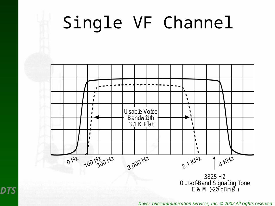
Single VF Channel
3825 HZOut-of-Band Signaling Tone
E & M (-20 dBmØ)
Usable VoiceBandwidth3.1 K Flat
DTS Dover Telecommunication Services, Inc. © 2002 All rights reserved
Baseband Elements
• The Analog Basebands consist of – Baseband amplifiers– Baseband bridges– Roofing filters– Group converters– Pilot stop filters– Orderwire and Service Channels– Alarm and control devices
DTS Dover Telecommunication Services, Inc. © 2002 All rights reserved
Analog and Digital SignalProcessing
• An analog baseband is the composite of all – Voice and HF tones– Noise in each channel– Cumulative system noise
• Analog means Amplify

DTS Dover Telecommunication Services, Inc. © 2002 All rights reserved
Digital Interfaces
• T1 – DS3 Interface– Interconnection into a digital radio– Conform to ANSI standards– Use Standard DSX Panels
• Layout
• Wiring protocol
• Making a cross-connect

DTS Dover Telecommunication Services, Inc. © 2002 All rights reserved
North American Digital Hierarchy
DS0 4KHz – 1DS0 64Kb/s
DS1 24 – DS0 1.544Mb/s
DS3
(STS 1)
672 – DS0 45.736Mb/s
(51.840Mb/s)
OC3 - Optical
(STS 3) – Elec.
2016 – DS0 155.220Mb/s
OC12 8064 – DS0 622.08Mb/s
OC 48 32,256 – DS0 2488.32Mb/s
OC192 129,024 – DS0 9953.28Mb/s
DTS Dover Telecommunication Services, Inc. © 2002 All rights reserved
RF Carriers
• Radio Frequencies (RF) are defined as:– Periodic waves capable of traveling thru space.– Waveforms that meet the conditions of
Maxwell’s Equations.– Always periodic electro-magnetic wave fronts.– Always consist of three core elements . . .

DTS Dover Telecommunication Services, Inc. © 2002 All rights reserved
Modulation
• RF carriers exist as CW with no external modulation – variation.
• To Modulate is to vary, such as:– Change Amplitude –AM– Change Frequency – FM– Change Phase – Ø

DTS Dover Telecommunication Services, Inc. © 2002 All rights reserved
CW Wave
TEK492PGM
REFLEVEL 0 DBM
FREQUENCY6.535 GHzCEN DBM
SPAN/DIV 10 MHz
10 DB/VERTICALDISPLAY
30 DBRF
ATTENUATION
3.0 — 7.1FREQ
RANGE
INT 1 MHzRESOLUTIONBANDWIDTH
0
-10
-20
-30
-40
-50
-60
-70
-80

DTS Dover Telecommunication Services, Inc. © 2002 All rights reserved
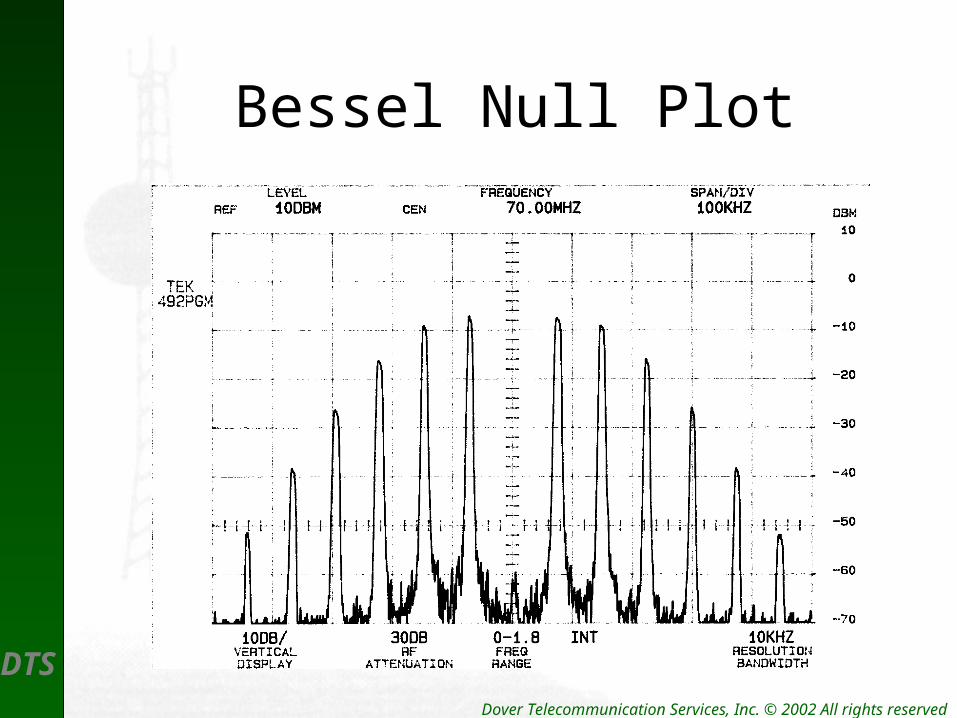
FM Modulation
• When a carrier is frequency modulated the following occur:– The frequency changes – The amplitude in the fundamental carrier
changes.– Multiple sidebands now have carrier power– For Example . . .
DTS Dover Telecommunication Services, Inc. © 2002 All rights reserved
Bessel Null Plot
DTS Dover Telecommunication Services, Inc. © 2002 All rights reserved
Baseband to RF
• After signal combination the following occur:– Passage through Pre-emphasis– Modulation of RF carrier
• FM Typical
• PM Possible

DTS Dover Telecommunication Services, Inc. © 2002 All rights reserved
Pre-emphasis & De-emphasis Networks

DTS Dover Telecommunication Services, Inc. © 2002 All rights reserved
Modulator Analog Radio
75
-25 dBm
FrequencySynth sizer
BBTEST
IN
30 dB
-55 dBm
AntennaMonitor-30 dBc
+30 dBm(+24 dBmOptional)
WGCMR 137
Antenna Coupling Unit
-20 dBm
HF Signal
Pre-emphasis
Composite TLP
ModulationHere
AntennaCouplingCarrier
Osc.

DTS
Digital Microwave
Digital Systems
Digital Transmitters
Digital Receivers

DTS Dover Telecommunication Services, Inc. © 2002 All rights reserved
Typical System Configuration
DTS Dover Telecommunication Services, Inc. © 2002 All rights reserved
Digital Transmitter
• Digital Transmitters contain the following:– Pulse input equipment (I/O Interface)
• Pulse Conversion• TDM Mux for multiple signals • LBO
– Band Pass Filters – BPF– RF Carrier Source Oscillators– I and Q splitters – Summing Amplifiers– Power Amplifiers
DTS Dover Telecommunication Services, Inc. © 2002 All rights reserved
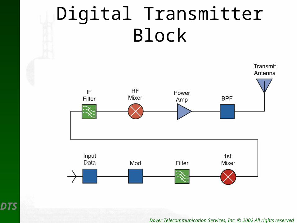
Digital TransmitterBlock
DTS Dover Telecommunication Services, Inc. © 2002 All rights reserved
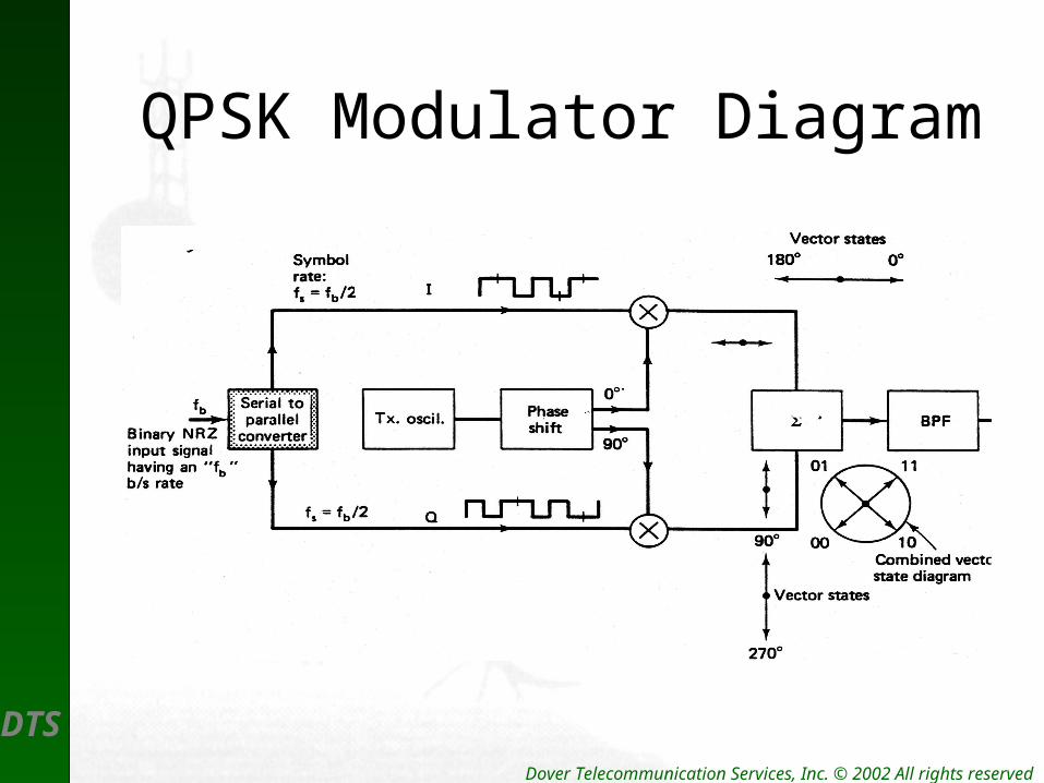
QPSK Modulator Diagram
DTS Dover Telecommunication Services, Inc. © 2002 All rights reserved
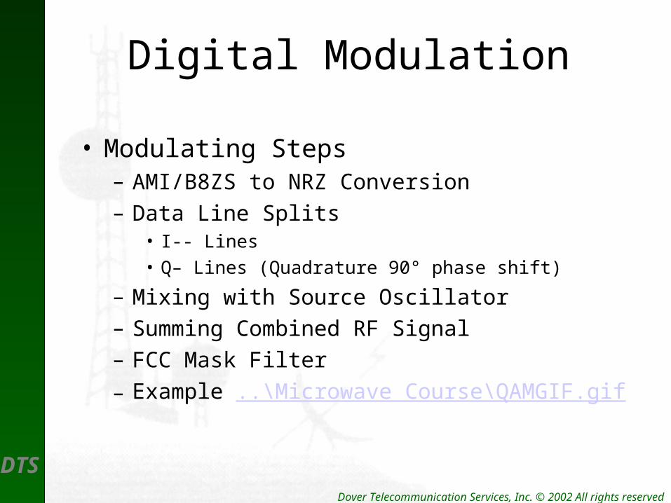
Digital Modulation
• Modulating Steps– AMI/B8ZS to NRZ Conversion
– Data Line Splits• I-- Lines
• Q– Lines (Quadrature 90° phase shift)
– Mixing with Source Oscillator
– Summing Combined RF Signal
– FCC Mask Filter
– Example ..\Microwave Course\QAMGIF.gif

DTS Dover Telecommunication Services, Inc. © 2002 All rights reserved
Signal Processing
• DS1 Signals arrive at Modem (I/O) as– AMI– B8ZS– 1.544mb/s / T1
• DS3 Signals arrive at Modem (I/O) as– B3ZS– 44.736mb/s / DS3
• OC3 Signals arrive at HLM on Fiber @– 155.220mb/s

DTS Dover Telecommunication Services, Inc. © 2002 All rights reserved
Signals Change
• Signals are converted to NRZ signals
• Signals are passed thru a LPF

DTS Dover Telecommunication Services, Inc. © 2002 All rights reserved
Simple Digital Modulation Techniques
0 1 1 0 0 0 1 1 Baseband
ASK0 = +/- 250 mV1 = +/- 500 mV
FSK0 = - 4.5 Khz1 = +4.5 Khz
PSK0 = 0°1 = 180°
DTS Dover Telecommunication Services, Inc. © 2002 All rights reserved
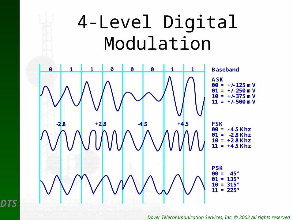
4-Level Digital Modulation
0 1 1 0 0 0 1 1 Baseband
ASK00 = +/- 125 mV01 = +/- 250 mV10 = +/- 375 mV11 = +/- 500 mV
FSK00 = - 4.5 Khz01 = -2.8 Khz10 = +2.8 Khz11 = +4.5 Khz
PSK00 = 45°01 = 135°10 = 315°11 = 225°
-2.8 +2.8 -4.5 +4.5

DTS Dover Telecommunication Services, Inc. © 2002 All rights reserved
QPSK PatternQ
00100
01
1
0111
I
DTS Dover Telecommunication Services, Inc. © 2002 All rights reserved
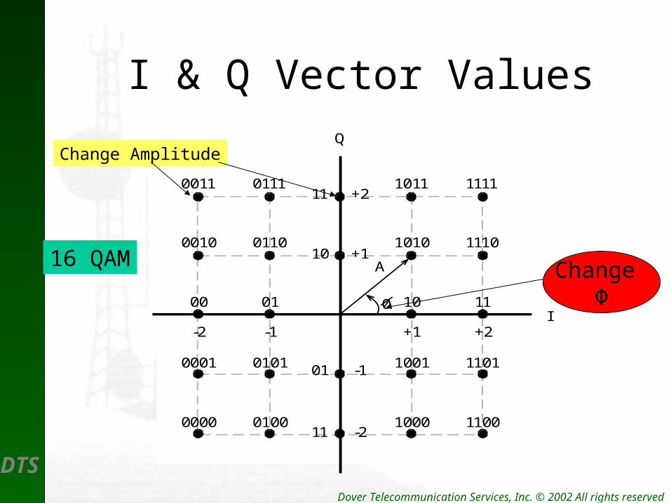
I & Q Vector ValuesQ
I
0011 0111 1011 1111
0010 0110 1010 1110
0001 0101 1001 1101
0000 0100 1000 1100
00 01 10 11
A
0
-2 -1 +1 +2
11 +2
10 +1
01 -1
11 -2
16 QAM
Change Amplitude
Change Φ
DTS Dover Telecommunication Services, Inc. © 2002 All rights reserved
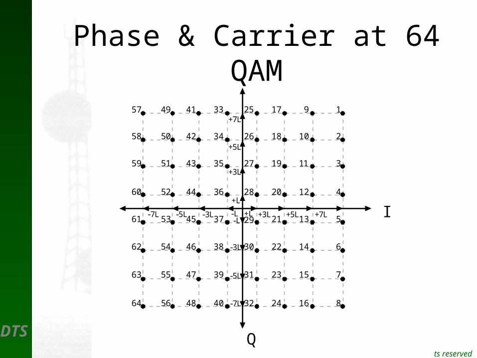
Phase & Carrier at 64 QAM
1
2
3
4
5
6
7
8
9
10
11
12
13
14
15
16
17
18
19
20
21
22
23
24
25
26
27
28
29
30
31
32
33
34
35
36
37
38
39
40
41
42
43
44
45
46
47
48
49
50
51
52
53
54
55
56
57
58
59
60
61
62
63
64
+7L
+5L
+3L
+L
-L
-3L
-5L
-7L
-7L -5L -3L -L +L +3L +5L +7L I
Q
DTS Dover Telecommunication Services, Inc. © 2002 All rights reserved
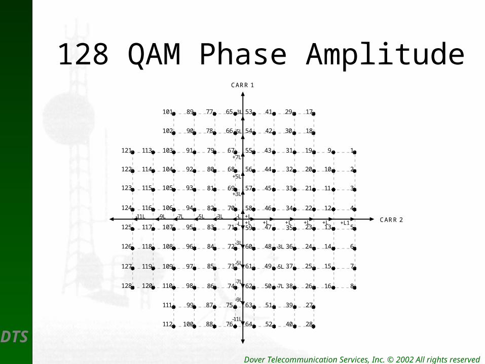
128 QAM Phase AmplitudeCARR 1
CARR 2
1
2
3
4
5
6
7
8
9
10
11
12
13
14
15
16
19
20
21
22
23
24
25
26
31
32
33
34
35
36
37
38
43
44
45
46
47
48
49
50
55
56
57
58
59
60
61
62
67
68
69
70
71
72
73
74
79
80
81
82
83
84
85
86
+7L
+5L
+3L
+L-L
-3L
-5L
-7L
-7L -5L+L +L +L +L1
27
28
39
40
51
52
63
64
75
76
-3L
-5L
17
18
29
30
41
42
53
54
65
66
-3L
-5L
87
88
77
78
99
100
111
112
89
90
101
102
91103113
92104114
93105115
94106116
95107117
96108118
97109119
98110120
121
122
123
124
125
126
127
128-7L
-9L
-11L
-L-3L-9L-11L+L +L
DTS Dover Telecommunication Services, Inc. © 2002 All rights reserved
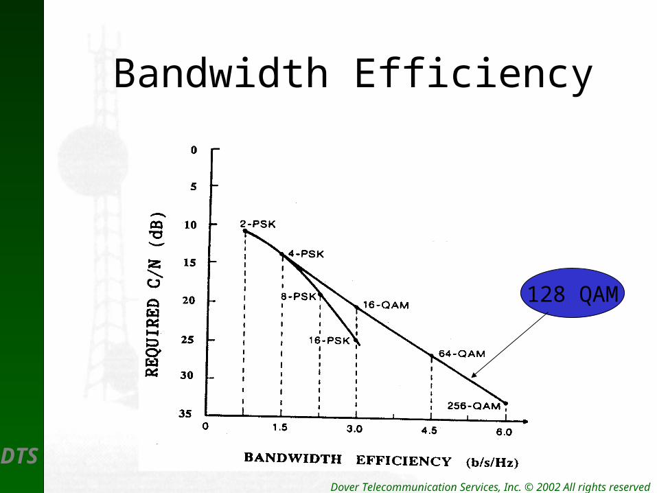
Bandwidth Efficiency
128 QAM
DTS
Microwave PowerAmplifiers
Amplifier Characteristics
Amplifier Distortion
Amplifiers as Oscillators
DTS Dover Telecommunication Services, Inc. © 2002 All rights reserved
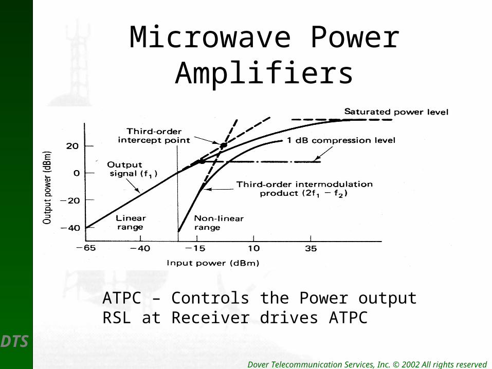
Microwave Power Amplifiers
ATPC – Controls the Power outputRSL at Receiver drives ATPC

DTS
Microwave Receivers
Receiver Elements
Receiver Process
DTS Dover Telecommunication Services, Inc. © 2002 All rights reserved
Receiver Characteristics
• Receiver Selectivity
• Receiver Sensitivity
• The RSL Curve
• The Digital Carrier– Carrier Recovery– Timing Recovery
DTS Dover Telecommunication Services, Inc. © 2002 All rights reserved
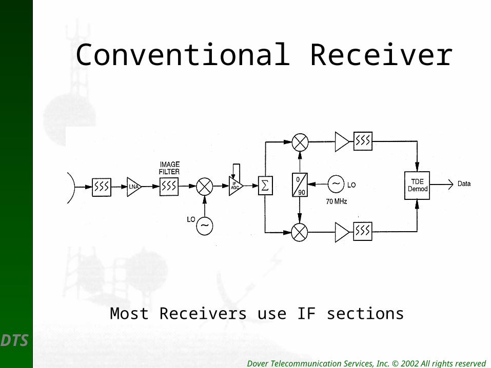
Conventional Receiver
Most Receivers use IF sections
DTS Dover Telecommunication Services, Inc. © 2002 All rights reserved
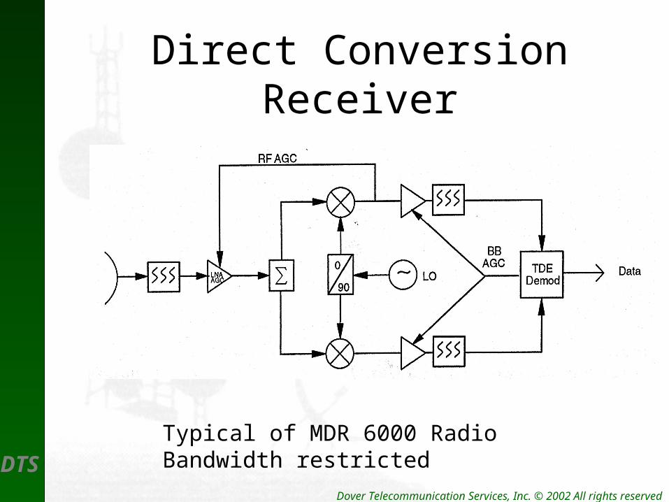
Direct Conversion Receiver
Typical of MDR 6000 RadioBandwidth restricted
DTS Dover Telecommunication Services, Inc. © 2002 All rights reserved
Digital IF Sections
• The digital IF section performs:– Equalization– Interference suppression– Signal stability
DTS Dover Telecommunication Services, Inc. © 2002 All rights reserved
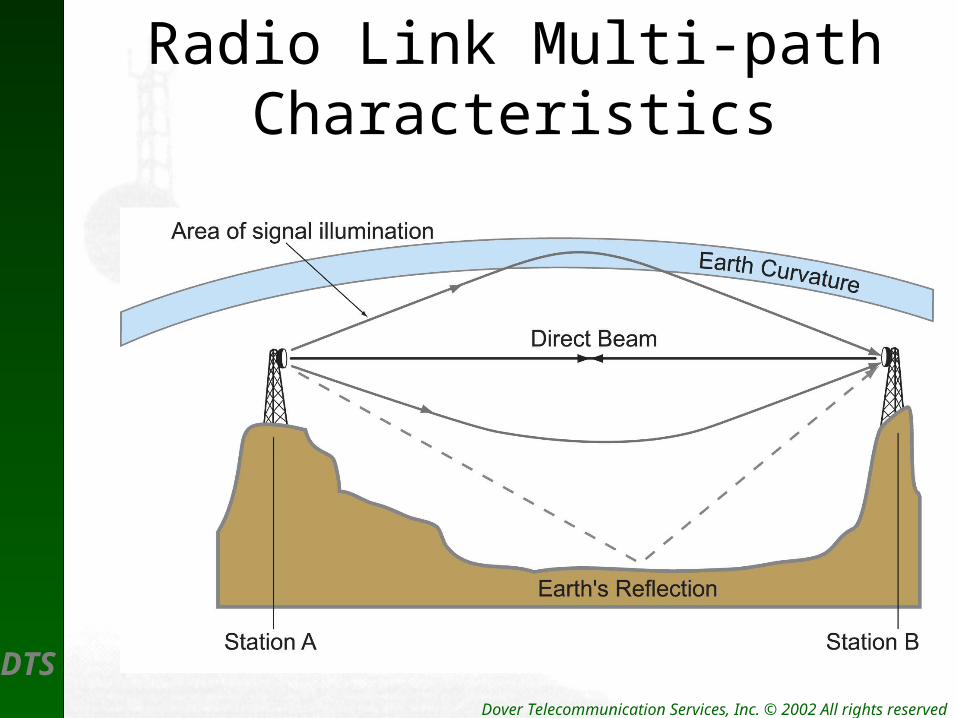
Radio Link Multi-path Characteristics
DTS Dover Telecommunication Services, Inc. © 2002 All rights reserved
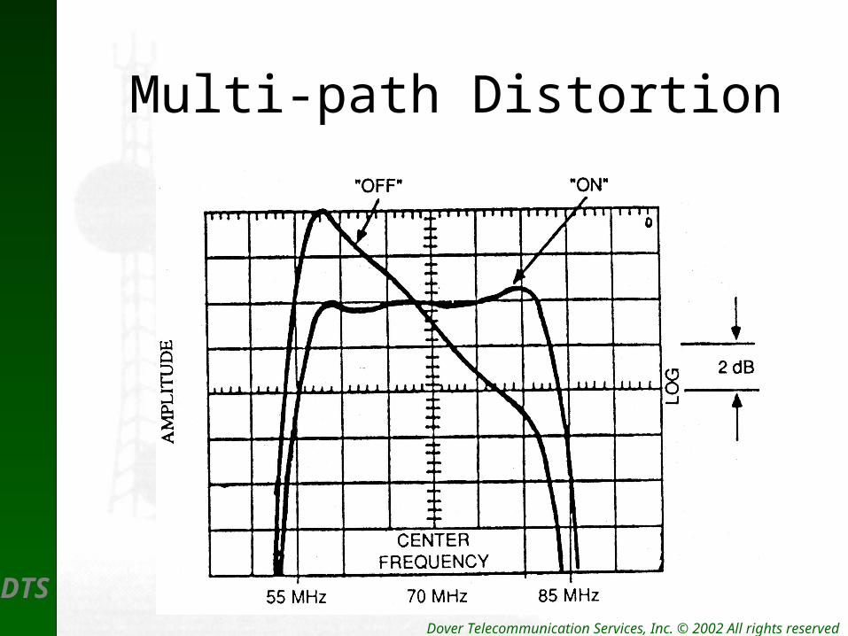
Multi-path Distortion
DTS Dover Telecommunication Services, Inc. © 2002 All rights reserved
Carrier Recovery
• Threshold for 10-6 BER Rate
• Ability to detect incoming carrier– Effects of SSBSC Modulation– Local Source Oscillator – Locking signal– Pulse Timing Recovery
DTS Dover Telecommunication Services, Inc. © 2002 All rights reserved
Data Recovery
• Receivers detect and reconstruct original data – Block Coding
• Reed-Solomon
• Galois
• Hamming
– Convolution Code

DTS Dover Telecommunication Services, Inc. © 2002 All rights reserved
Error Detection
• There is a difference between Detecting an Error and Correcting an Error– Common errors detected are:
• CRC
• BCH
• Bit Errors

DTS Dover Telecommunication Services, Inc. © 2002 All rights reserved
Forward Error Correction(FEC)
• Common methods of detecting and Correcting data bit errors are:– BCH used in most SCADA applications– Reed-Solomon
• A Block Code
• Uses Parity checks
DTS Dover Telecommunication Services, Inc. © 2002 All rights reserved
Reed-Solomon Codes
• Capable of Correcting a Single Error Symbol.• Similar to BCH Error Codes• Used in Harris Constellation Radio• Is Considered a Block Code
DTS Dover Telecommunication Services, Inc. © 2002 All rights reserved
The Eye-Pattern
• True status of pulse recovery
• Determines jitter in timing circuit
• Determines Inter-symbol-Interference (ISI)
DTS Dover Telecommunication Services, Inc. © 2002 All rights reserved
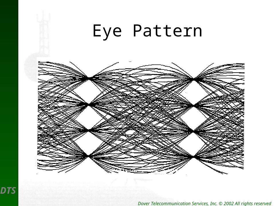
Eye Pattern

DTS Dover Telecommunication Services, Inc. © 2002 All rights reserved
Single Sweep of Eye Pattern
DTS Dover Telecommunication Services, Inc. © 2002 All rights reserved
The Terminal ACU
• The Antenna Coupling Unit – Circulates the TX and RX Signals– Isolate the TX from the RX– Protects amplifiers and filters

DTS Dover Telecommunication Services, Inc. © 2002 All rights reserved
Antenna Coupling
DTS Dover Telecommunication Services, Inc. © 2002 All rights reserved
Network Management
• Digital networks are often managed by a central system
• Internet Management Protocol (SNMP)
DTS
Testing Applications
Testing T1 Circuits
Test Set Operation
Test Patterns
Error Reporting
DTS Dover Telecommunication Services, Inc. © 2002 All rights reserved
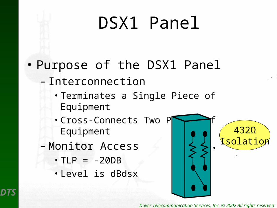
DSX1 Panel
• Purpose of the DSX1 Panel– Interconnection
• Terminates a Single Piece of Equipment
• Cross-Connects Two Pieces of Equipment
– Monitor Access• TLP = -20DB
• Level is dBdsx
432ΩIsolation

DTS Dover Telecommunication Services, Inc. © 2002 All rights reserved
Terminating T1 Spans
Test Equipment terminates the circuit as follows:
Bridge = > 1000Ω
Term = 100Ω
DSXMON = 100Ω/Gain
Signal Level typically:
6v P-P = 0dBdsx
ZL= 100 Ω
DTS Dover Telecommunication Services, Inc. © 2002 All rights reserved
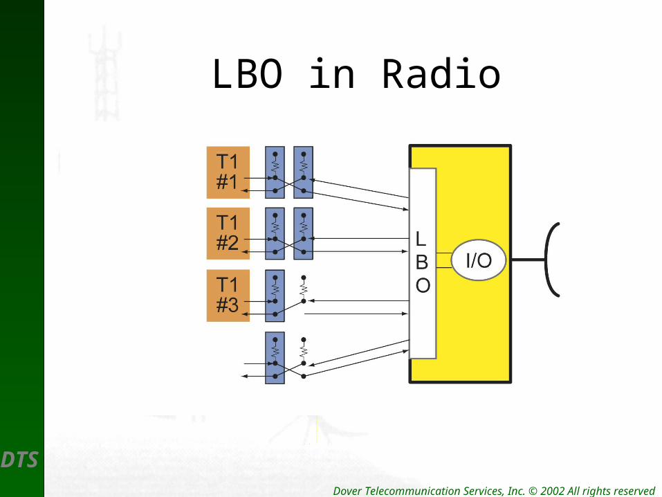
LBO in Radio

DTS Dover Telecommunication Services, Inc. © 2002 All rights reserved
T1 Configurations4 – T1 Radio
T1#1
T1#4
LBO
T1#2
T1#3
M12I/O
Each T1Has LBOSetting
DTS Dover Telecommunication Services, Inc. © 2002 All rights reserved
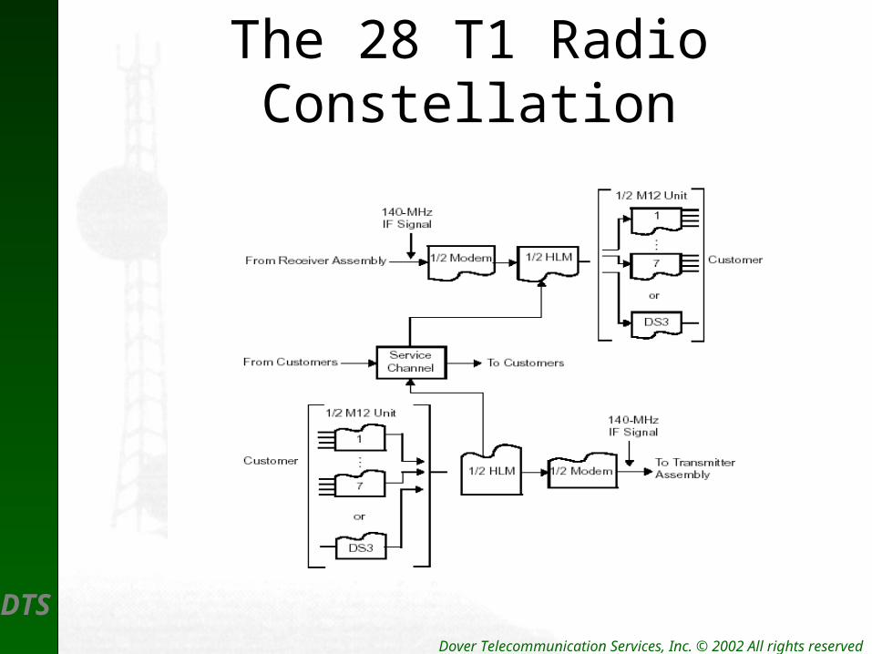
The 28 T1 RadioConstellation
DTS Dover Telecommunication Services, Inc. © 2002 All rights reserved
DS3 Microwave Interface
• Up to 3 DS3 Signals can be Connected • Data Rate can Interface to OC3• Fiber and Copper make a Connection• DS3-DSX Panel Connections• The DS3 Copper Connection –RG59
DTS Dover Telecommunication Services, Inc. © 2002 All rights reserved
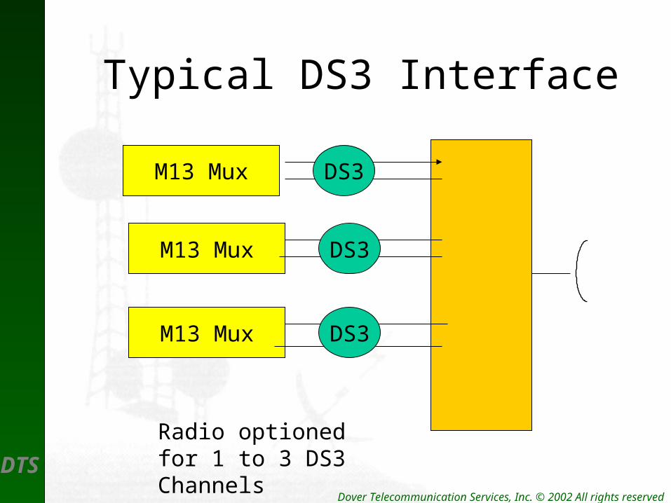
Typical DS3 Interface
M13 Mux
M13 Mux
M13 Mux
DS3
DS3
DS3
Radio optioned for 1 to 3 DS3 Channels

DTS Dover Telecommunication Services, Inc. © 2002 All rights reserved
Constellation DS3Terminal

DTS Dover Telecommunication Services, Inc. © 2002 All rights reserved
Digital Overview
• T1 Framing
• T1 Line Codes
• T1 Timing
• T1 Signal Levels

DTS Dover Telecommunication Services, Inc. © 2002 All rights reserved
Network Elements
• DSX Panels – T1 and DS3 Electrical
• T1 Devices– Channel Banks– NIU’s to Telco Network– CSU – FT1

DTS Dover Telecommunication Services, Inc. © 2002 All rights reserved
DS3 Overview
• Channelized Vs Unchannelized
• M13 Mux– Low Speed– High Speed
• Electrical Interface – DS3 & STS
• Optical Interface – T1 to OC-192

DTS Dover Telecommunication Services, Inc. © 2002 All rights reserved
Test Equipment Setup
1ST
What to Test

DTS Dover Telecommunication Services, Inc. © 2002 All rights reserved
Test Signals
Test Pattern REPLACES Traffic on T1Span . . . INTRUSIVE
DTS Dover Telecommunication Services, Inc. © 2002 All rights reserved
Common Test Patterns
• All Zeros – AMI/B8ZS Provisioning
• All Ones – Copper – Max 1’s
• 3 in 24 – Stress to AMI Circuits– Minimum 1’s density 1/8– 15 Consecutive 0’s
• QRSS – Voice = average 1’s
DTS Dover Telecommunication Services, Inc. © 2002 All rights reserved
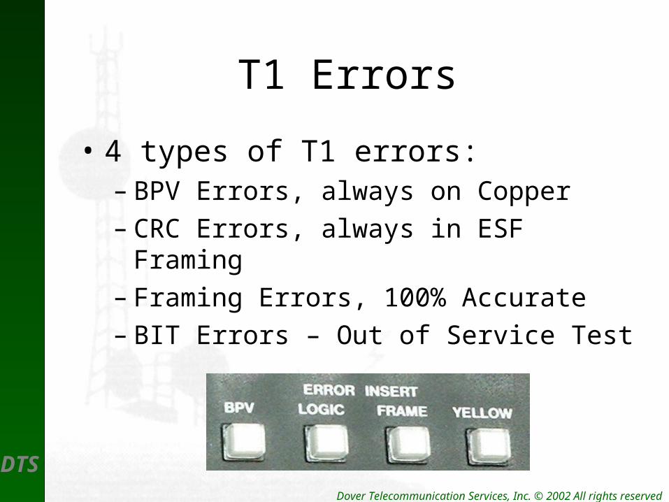
T1 Errors
• 4 types of T1 errors:– BPV Errors, always on Copper– CRC Errors, always in ESF Framing– Framing Errors, 100% Accurate– BIT Errors – Out of Service Test
DTS Dover Telecommunication Services, Inc. © 2002 All rights reserved
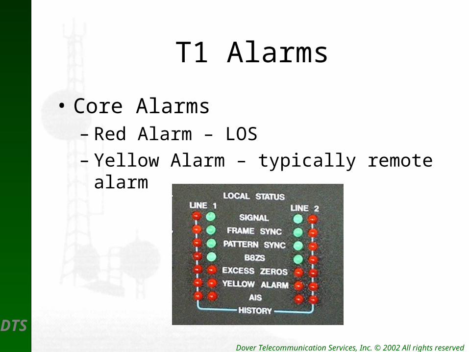
T1 Alarms
• Core Alarms– Red Alarm – LOS– Yellow Alarm – typically remote alarm
DTS Dover Telecommunication Services, Inc. © 2002 All rights reserved
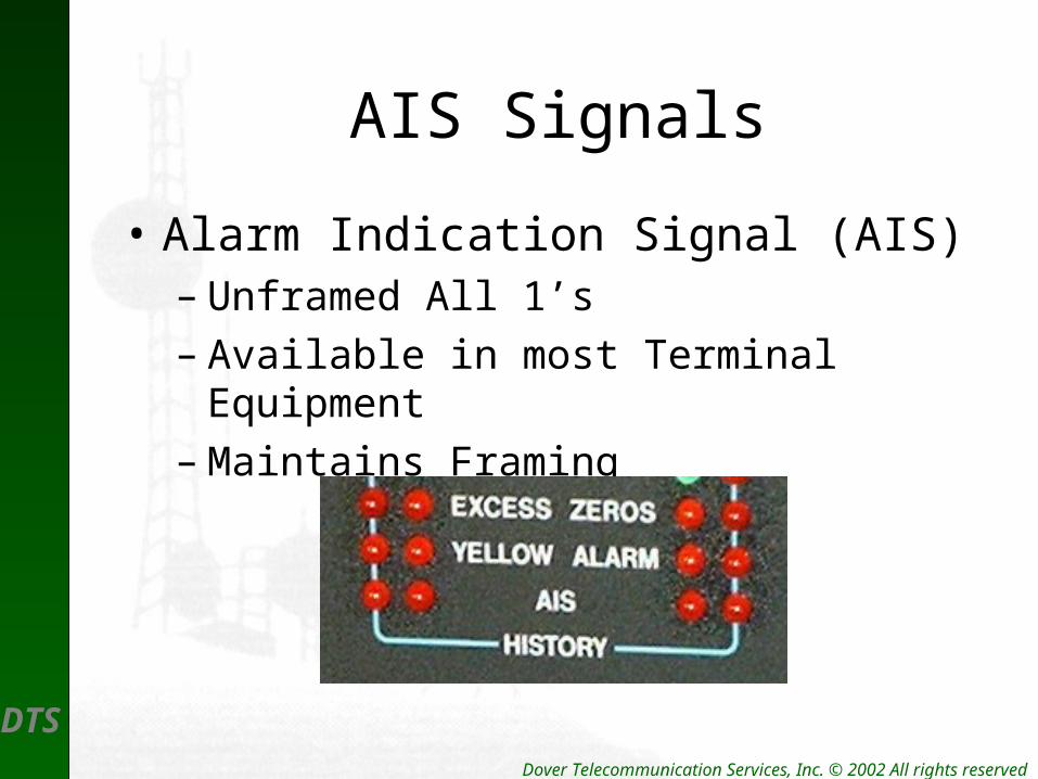
AIS Signals
• Alarm Indication Signal (AIS)– Unframed All 1’s– Available in most Terminal Equipment– Maintains Framing

DTS Dover Telecommunication Services, Inc. © 2002 All rights reserved
T1 Loopbacks
• Available in most Terminal Equipment– Coastcom Mux– Microwave Radio– Digital Cross-connect (DCS)– CSU– NIU