dual - buyaparcel.com · dual exposed shower with fixed and adjustable shower heads...
TRANSCRIPT

Dual exposed shower with fixed and adjustable shower heads installation instuctions page 1
DualExposed shower with fixed and adjustable
shower heads

Dual exposed shower with fixed and adjustable shower heads installation instuctions page 2
Shower systems
Exposed shower with fixed
and adjustable shower heads

Dual exposed shower with fixed and adjustable shower heads installation instuctions page 3
Components

Dual exposed shower with fixed and adjustable shower heads installation instuctions page 4
Important information
Introduction
The Dual product is an exposed shower complete with fixed and adjustable height shower heads. Dual thermostatic valves provideclose temperature stability and fail safe protection on appropriate high pressure systems.
The Dual product is suitable for use on high pressure, combination boiler and boosted gravity systems.
The Dual product is supplied with a 5 year guarantee.
Safety information
This product must be installed by a competent person in accordance with all relevant current Water Supply Regulations.
THE SHOWER MUST NOT BE USED WITH A HOT WATER SUPPLY TEMPERATURE OVER 65 C.
The Dual product is designed for domestic use only.
Product specification
Dual products are suitable for balanced high pressure, combination boiler systems and boosted gravity systems. Pressure range1.0* – 10 bar max (static).
* The combination boiler MUST have a minimum rating of 24kW (80,000 Btu) and be of the type fitted with a fully modulatinggas valve.
If in any doubt, please contact the appliance manufacturer before installation commences.
ConnectionsThe Dual product is designed for conventional supplies with HOT on the Left and COLD on the Right as viewed from the front.Supply lines must be flushed clear of any debris before installation of the unit. Any debris accumulation in the shower valve andhead may result in damage and poor performance.
FlushingSome modern fluxes can be extremely corrosive and, if left in contact, will attack the working parts of this unit. All soldering mustbe completed and the pipe work thoroughly flushed out in accordance with current Water Supply Regulations prior to connectionof the product.
FiltersTo ensure optimum ongoing performance, Dual products are protected by inlet filter assemblies in the internal waterways. Debrisaccumulation may result in progressively reduced flow through the showerhead and noisy operation.
Isolating valvesSuitable full way isolation valves must be fitted to both supplies in accordance with current Water Supply Regulations and ourterms of warranty.Due to their restrictive characteristics, stopcocks and ball type valves that reduce the pipe bore size must not be used on gravitypumped installations.
PressuresThe Dual cartridge is designed to operate from the mains at a maximum of 10 bar. If the mains pressure exceeds 5 bar a ‘droptight’ PRV must be fitted on the supply pipe after the main stopcock. A setting of 3 bar is recommended. It should be noted thatdaytime pressures approaching 8 bar can rise above the stated maximum overnight.
A suitable PRV is available from Aqualisa.
If the dynamic (running) pressure is greater than 2 bar a bottom outlet flow regulator will be required. Please contact Aqualisacustomer service on 01959 560010.
! The Dual product is not suitable for mixed supply systems, e.g. gravity hot and mains cold.

Dual exposed shower with fixed and adjustable shower heads installation instuctions page 5
Important information
Combination boiler/multipoint system
The Dual product is suitable for use with combination boiler systems. The combination boiler MUST have a minimum rating of24kW (80,000 Btu) and be of the type fitted with a fully modulating gas valve. This is sufficient to operate one outlet point ata time.
If in any doubt, please contact the appliance manufacturer before installation commences.
The cold supply can be taken from the nearest convenient mains supply and the hot supply can be taken from the nearest hotwater draw-off point. Account must be taken of the pressure drops that will occur when other draw-off points are used while theshower is in use.
Balanced high-pressure system
The cold water supply must be drawn from the same mains supply as that to the hot water system (down stream of the cylindermanufacturers pressure limiting valve, where supplied) and the hot supply from the nearest convenient draw off point. Accountmust be taken of pressure drops that may occur when other draw-off points are used while the shower is in use.
Boosted gravity fed hot and cold supplies
Services must be installed according to good plumbing practice having regard to pipe sizing, long pipe runs and low-headsituations.
Pump installation
PLEASE REFER TO THE MANUFACTURERS PUMP INSTALLATION GUIDE FOR PUMP INSTALLATION INFORMATION.
UNDER NO CIRCUMSTANCES MUST A PUMP BE FITTED DIRECTLY TO THE WATER MAIN.
A pump must only be used to boost the pressure from tank-fed supplies.
A minimum 1 bar twin ended booster pump may be fitted with the Dual mixer shower, but for improved performance,we recommend a twin ended booster pump larger than 1 bar is used.
Stored water capacities
The minimum capacity of the cold storage cistern should not be less than 225 litres (50 gallons). The capacity of the hot cylindermust be capable of meeting the anticipated demand.
CYLINDER TEMPERATURE IN EXCESS OF 65ºC MAY RESULT IN POOR SHOWER PERFORMANCE.
To minimise pressure loss we recommend that the hot and cold supplies are run in 22mm as close as reasonably possible to themixing valve before reducing to 15mm to suit the intended inlet connection fittings.
Siting
With boosted gravity fed systems, please ensure the minimum gravity flow rate is sufficient to operate the pump flow switches.
PLEASE REFER TO THE MANUFACTURERS PUMP INSTALLATION GUIDE FOR PUMP INSTALLATION INFORMATION.

Dual exposed shower with fixed and adjustable shower heads installation instuctions page 6
Step-by-step instructionsIn addition to the guide below it is essential that the written instructions
overleaf are read and understood and that you have all the necessary
components (shown overleaf) before commencing installation. Failure to
install the product in accordance with these instructions may adversely affect
the warranty terms and conditions. Do not undertake any part of this
installation unless you are competent to do so. Prior to starting ensure that
you are familiar with the necessary plumbing regulations required to install
the product correctly and safely.
A first fix easy fit fixing bracket is available
separately, product code MD300EFB, designed
for ease of installation. If required, fit the easy
fit bracket following the installation instruction
sheet supplied with the bracket and proceed to step 6 below.
If using the MD300EFB bracket ensure sufficient threads are left from the
finished wall surface, after the cover plates have been fitted, to ensure
adequate purchase for the exposed valve.
The exposed valve and fixing bracket assembly MUST NOT be used as a
grab rail support method.
!
!
If required, apply jointing tape to the threads
and fit the eccentric elbow connectors
sufficiently to achieve a water tight seal,
terminating at 150mm centres to suit the
exposed valve inlets.
2
Ensuring adequate provision to allow the water to discharge safely to waste,
turn on the supplies to flush the system through. Attach pressure test equipment
and pressure test the system in accordance with Water Supply Regulations.
3
Eccentric elbows are provided to allow for inlet pipework adjustment between
130mm – 170mm centres. Construct suitable connections terminating in
½”BSP female fittings.
When using the eccentric elbows provided we recommend leaving sufficient
threads from the finished wall surface, after the cover plates have been
fitted, to ensure adequate purchase for the exposed valve.
If using alternative fixings please refer to the installation instructions
provided to ensure adequate threads are left to connect the exposed valve
after the cover plates have been fitted to the finished wall surface.
1
!
Ensure the ¾” supply connections are temporarily capped to prevent any dirt or
dust ingress into the pipe work during the making good process. Remove the
caps prior to connecting the shower valve.
4

Dual exposed shower with fixed and adjustable shower heads installation instuctions page 7
Ensuring the washers are positioned within the
valve inlets, offer the valve into position.
Tighten the fixing nuts using a suitable tool
taking care not to overtighten.
8
Place the cover plates onto the exposed ¾” threads, flush with the finished wall
surface and apply a thin bead of mastic if required.5
Remove the grub screws from the valve control knob levers and set aside.6
Secure the grub screws to the valve control
knobs using the hexagonal key provided and fix
the levers to the control knob assemblies.
7
Ensuring the sealing washer is in position,secure the top outlet valve connector to thevalve and tighten using a suitable tool,taking care not to overtighten.
9
Ensuring the handset cradle is on the left
hand side of the rail, pass the rail through the
handset holder whilst keeping the slider button
depressed.
1
Fixed & adjustable height head assembly
Remove the cover plate and pass the straight riser tube through the wallfixing bracket.2

Dual exposed shower with fixed and adjustable shower heads installation instuctions page 8
Fit the formed shower arm to the straightriser tube.
The straight riser tube is a fixed length andis not suitable to cut down.
3
Ensuring the O’ring and nut is secure on theriser tube, locate the rail assembly intoposition within the valve top outlet and pushfully home.
4
Carefully slide the wall bracket up the risertube assembly to conceal the join betweenthe straight and formed riser tubes.
5
Ensuring the riser tube assembly has beencorrectly positioned and attached to themixer valve, mark the position of the fixingplate. Remove the riser tube assembly fromthe valve and remove the bracket assemblyfrom the riser rail.
6
Remove the fixing plate from the wallbracket assembly using the hexagonal keyprovided.
7
Place the fixing plate into position and mark and prepare the fixing pointsusing the fixings provided, if suitable.8
!
Secure the fixing plate to the wall using the
screws provided, if suitable.9

Dual exposed shower with fixed and adjustable shower heads installation instuctions page 9
Carefully slide the coverplate onto the wallbracket.11
Re-position the rail assembly into place in the mixer valve outlet and pushfully home. Tighten the fixing nut using a suitable tool, taking care not toovertighten.
12
Secure the wall bracket to the fixing plateusing the heagonal key provided. Carefullysecure the cover plate flush with thefinished wall surface.
13
Ensuring the hose washer is in place, attachthe hose to the hose outlet, taking care not toovertighten. Turn the shower on towards thewall to allow the water to discharge safely towaste and run the shower for a few seconds toclear any debris in the outlet assembly.
This process can also be repeated for the fixedhead by adjusting the control knob away fromthe wall.
14
Ensuring the flat washer is in place, carefullyscrew the shower head to the formed armtaking care not to damage the platedsurface. Carefully tighten the shower headwith a suitable tool taking care not toovertighten.
15
Ensuring the wall bracket is in the correct position on the riser rail assembly,secure the wall bracket to the rail via the grub screw in the rear of the wallbracket using a suitable hexagonal key.
This will prevent the rail from rotating when fitted to the mixer shower.
10
!
Dual exposed shower with fixed and adjustable shower heads installation instuctions page 10
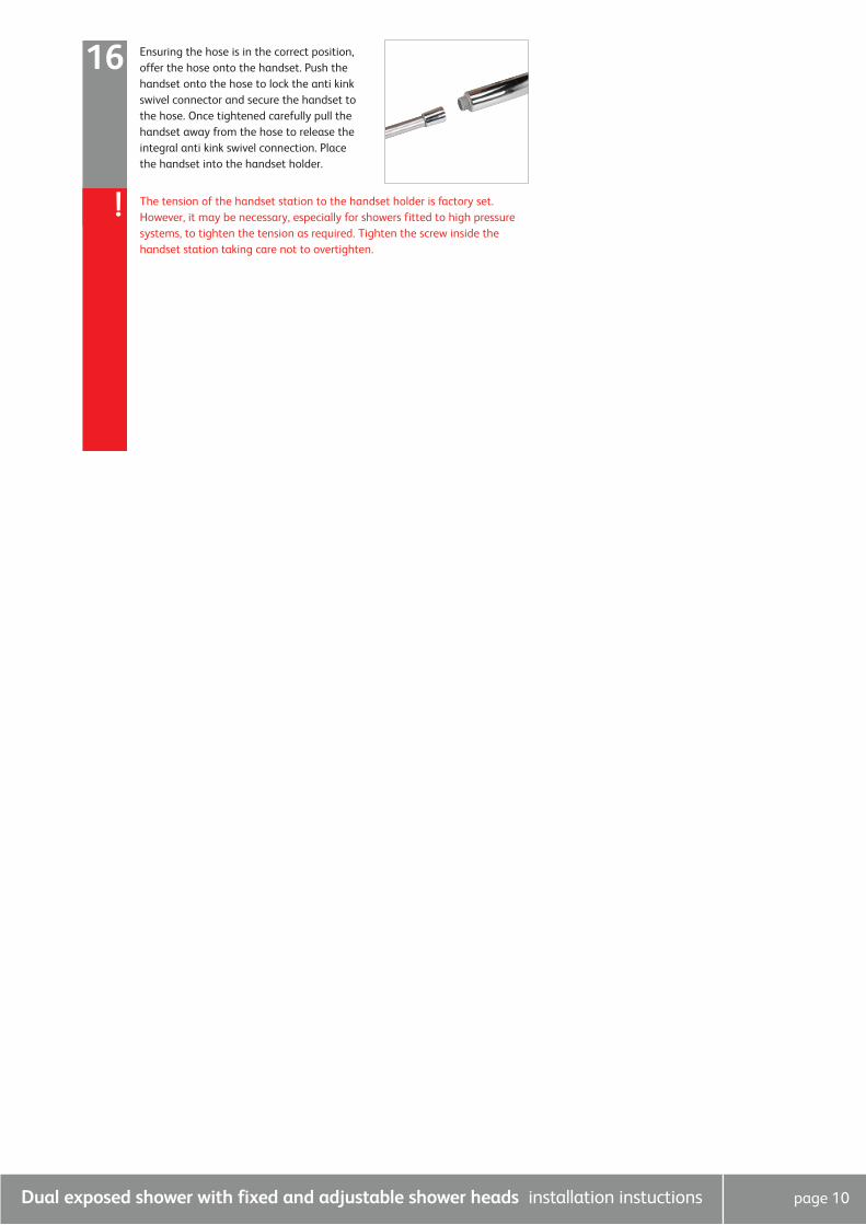
Ensuring the hose is in the correct position,offer the hose onto the handset. Push thehandset onto the hose to lock the anti kinkswivel connector and secure the handset tothe hose. Once tightened carefully pull thehandset away from the hose to release theintegral anti kink swivel connection. Placethe handset into the handset holder.
16
The tension of the handset station to the handset holder is factory set.However, it may be necessary, especially for showers fitted to high pressuresystems, to tighten the tension as required. Tighten the screw inside thehandset station taking care not to overtighten.
!

Dual exposed shower with fixed and adjustable shower heads installation instuctions page 11
User guide – Shower valveShower operation
1. The Dual product features temperature control on the right hand side of the valve when viewed from the
front. When the lever is pointing upwards, the valve is in the mid blend position. To change the showering
temperature rotate the control away from the wall to increase the temperature and towards the wall to
decrease the temperature, using the markings as a guide.
THE MID BLEND TEMPERATURE IS DICTATED BY THE TEMPERATURE OF THE INCOMING SUPPLIES.
N.B. Should it be necessary to reset the maximum temperature position, please refer to the commissioning
instructions overleaf.We recommend the MAXIMUM outlet temperature is set to 460C.
2. Turn the valve on by rotating the control knob on the left side of the valve away from the wall to operate the
fixed head or towards the wall to operate the adjustable height head, using the icons as a guide. Turn the
valve off by rotating the control knob to the centre until a stop is reached and the lever is pointing upwards.
User guide – Adjustable shower headShower operation
NEVER ATTEMPT TO MAKE ANY ADJUSTMENT TO THE SHOWER HEAD BY PULLING ON THE SHOWER HOSE.
1. To select the preferred height for the shower head, press the handset holder button to enable the slider
to be moved up or down the rail.
2. Angular adjustment is made by carefully but firmly pulling forwards or pushing back the shower head
against the knuckle in the handset holder.
3. To select the desired spray pattern rotate the shower plate clockwise or anti-clockwise.
User guide – Fixed shower head
1. The shower head is mounted on a mulit-directional ball joint to allow angular adjustment in any direction
by carefully moving the head to the desired angle.
Cleaning and maintenance
Your Dual shower system should be cleaned using only a soft cloth and washing up liquid.
! DO NOT USE ABRASIVE CLEANERS.
To reduce the requirement for chemical descaling in hard water areas, the shower heads incorporate rub clean teats. Any scalebuild up that may occur in any of the holes can be broken down by gently rubbing the flexible tips of the jets during use.
Should chemical descaling of the head become necessary, remove the shower head and fully immerse in a mild proprietarydescalent.
IT IS IMPERATIVE THAT DESCALING IS CARRIED OUT STRICTLY IN ACCORDANCE WITH THE MANUFACTURERS INSTRUCTIONS.SUBSTANCES THAT ARE NOT SUITABLE FOR PLASTICS AND ELECTROPLATED SURFACES MUST NOT BE USED.

Dual exposed shower with fixed and adjustable shower heads installation instuctions page 12
Commissioning
1. Ensure that the hot water system is at normal maximum temperature.
2. Turn the temperature control knob to the mid-blend position (with the
lever at the top of the knob).
3. Carefully unscrew the lever from the knob and set aside.
4. Remove the temperature lever grub screw and set aside.
5. Using a suitable hexagonal key, loosen the grub screw and pull the
temperature control knob clear.
6. Turn the valve on.
7. Using a digital thermometer, rotate the cartridge spline to adjust the
temperature control to the required MAXIMUM temperature setting.
We recommend the MAXIMUM outlet temperature is set to 46OC.
8. Turn the valve off.
9. Using a suitable tool, remove the maximum temperature stop ring.
10. Reposition the temperature stop ring ensuring the maximum temperature
stop point aligns with the markings on the temperature spline.
11. Refit the temperature control knob onto the valve with a temperature
lever fixing point in the maximum temperature position.
12. Secure the knob to the valve and refit the temperature control lever
assembly.
! If required, the flow control knob can be removed following the
above procedure.
! THE DUAL PRODUCT RANGE IS PRE-SET TO A SAFE
MAXIMUM SHOWER TEMPERATURE. SHOULD IT BE
NECESSARY TO RESET THE MAXIMUM TEMPERATURE
POSITION, PLEASE OBSERVE THE FOLLOWING PROCEDURE.
WE RECOMMEND THE MAXIMUM OUTLET TEMPERATURE
IS SET TO 46OC.

Dual exposed shower with fixed and adjustable shower heads installation instuctions page 13
Trouble shooting guide
Water output is either all
hot or all cold, or cold only.
Symptom Possible cause Action
Reversed inlet supplies Check that the supplies
correspond with the inlet
markings
Water output is not hot
enough
The temperature of the hot
water cylinder is too low
Water flow through the
appliance is too fast
Water flow through the hot
water appliance is too fast
The cylinder temperature
should be at least 15˚c
hotter than the blend
Check the flow rate
recommendations with the
heater manufacturer
Adjust the flow control
knob on the mixer valve
to reduce flow until a
comfortable showering
temperature is achieved
Flow rate is poor and water
temperature is low
Airlock in the water supply Check that the pipe work is
laid in accordance with the
correct practices, paying
particular attention to
potential air-traps
Water temperature
regularly swings between
hot and cold
Cold water pressure is too
high
If the static water pressure
exceeds 10 bar, install
pressure reducing valve
(PRV) in accordance with
the installation guide
Poor flow rate Twisted hose
Debris in shower head
Debris in filters
Check and clear as
necessary

Aqualisa Products Limited
The Flyer’s Way
Westerham Kent TN16 1DE
Sales enquiries: 01959 560010
Republic of Ireland 01-864-3363
Customer helpline: 01959 560010
Republic of Ireland 01-844-3212
Brochure Hotline: 0800 652 3669
Website: www.aqualisa.co.uk
Email: [email protected]
Please note that calls may be recorded for training and quality purposes
The company reserves the right to alter, change or modify the product specifications without prior warning
® Registered Trademark Aqualisa Products Limited
Part No:649601 Issue 01 Nov 10