dual polarization synthesis and optimization of
TRANSCRIPT

Dual Polarization Synthesis and Optimization
of Cylindrical Offset Reflector Antenna for Cosecant-squared Radiation Pattern
R. Vahdani, T. Azad, V. Mohtashami and A. R. Attari
Department of Electrical Engineering, Ferdowsi University of Mashhad, Mashhad, Iran
[email protected]@gmail.com, [email protected], [email protected], [email protected] Corresponding Author: V. Mohtashami
Abstract- This paper presents the shaping optimization of an S-band cylindrical offset reflector antenna with cosecant-squared radiation pattern in elevation plane. The cross section of the antenna is mathematically modeled by a polynomial function and optimized by the genetic algorithm to obtain the desired pattern for both TE and TM polarizations. The physical optics method together with the uniform theory of diffraction is used to efficiently calculate the radiation pattern during the optimization. Numerical results show that the cosecant-squared radiation pattern can be achieved with good accuracy for angular span of 50
. The
computed radiation pattern agrees well with method of moments as well as CST software package and deviates less than about 0.7 dB, on average, from the ideal cosecant-squared pattern.
Index Terms-Cosecant-squared pattern, genetic algorithm, physical optics, reflector antenna, uniform theory of diffraction.
I. INTRODUCTION
Cosecant-squared radiation pattern is usually required by air surveillance radars in order to
guarantee constant power reception from a target that flies at a constant altitude [1]. Other
applications include ground mapping radars and wireless networks [2]. Various antenna
configurations such as Butler matrix [3], microstrip array [4], linear phased array [5] and
shaped reflector [6–10] have been suggested to achieve cosecant-squared radiation pattern.
Among them, shaped reflector antenna is a good choice due to its simple structure that is
straightforward to fabricate and does not need expensive beam-forming networks.
At low microwave frequencies, the size of the reflector is large and its surface roughness is
small with respect to the wavelength. Consequently, the Physical Optics (PO) method provides
proper accuracy and computational efficiency for the design and analysis of the reflector. When

supplemented by the uniform or physical theory of diffraction, the current distribution is
calculated with good accuracy all over the surface and near the edge of the reflector [11]. To
facilitate the design
Fig. 1. Desired normalized cosecant-squared radiation pattern.
process, a proper mathematical surface representation should be used. Polynomial function and
Fourier-Jacobi expansion are among the reported representations in the literature [6, 12].
This paper presents the synthesis and optimization of a cylindrical offset reflector antenna
that produces cosecant-squared radiation pattern in elevation plane at S-band frequencies. This
specific problem has practical applications in industry and was referred to the authors. The
cross section of the reflector is represented by a polynomial function. To achieve the desired
radiation pattern, the coefficients of the polynomial are optimized by using Genetic Algorithm
(GA). The design procedure yields cosecant-squared radiation pattern in both TE and TM
polarizations. The computational burden and the accuracy of the optimization process are
handled by using the physical optics method and Uniform Theory of Diffraction (UTD). Two
reference solutions, CST software as well as author-generated code based on the method of
moments, are used to validate the simulation results. Then, the radiation pattern of the designed
reflector antenna is compared with these reference solutions. It is assumed throughout the text
that a conventional feed (such as an open-ended waveguide or a horn antenna) with proper
matching has been used to feed the reflector.
The paper is organized as follows. The analysis and design of the antenna as well as shape
optimization are described in Section II. Numerical results and discussion are presented in
Section III and conclusions are given in section IV.

II. DESIGN AND ANALYSIS
The cosecant-squared radiation pattern of an antenna in the elevation plane over the range of
angles 1 2 is
2
0( ) cscG G (1)
where G0 is a constant that depends on the gain of the antenna. Fig. 1 shows the desired
normalized
Fig. 2. Geometry of the cylindrical offset reflector antenna, (a) 3D view, (b) cross section.
pattern in the angular span of the elevation plane. The horizon is assumed at 0 . Ideal
cosecant-squared pattern is desired over 1 2 whereas side lobe less than a predefined
level (e.g. -25 dB as shown in the figure) is required over 90 0 and 2 90 . The
region 10 is assumed as transition region. Typical values of 1 and 2 are a few degrees
and several tens of degrees respectively. To present the systematic procedure used for design
and optimization of the reflector, this section is divided into three subsections. The first
subsection describes geometry of the reflector and parameters of the feed. The second
subsection formulates the problem by using PO and UTD. The last subsection presents the
optimization process and the associated cost function.
A. Antenna Geometry
The geometry of the cylindrical reflector antenna is shown in Fig. 2(a). The reflector is flat
along the z-axis and is assumed very long compared to wavelength in that direction. As a result,
we deal with a 2-dimensional problem as shown in Fig. 2(b). The cross section of the antenna is
shaped to achieve cosecant-squared pattern in the elevation xy plane. Note that the cylindrical
reflector is flat along the z-axis and therefore radiates a pencil beam (sinc function) in the
azimuth xz plane [13].
The cross section of the offset reflector is represented as

( ) ;x f y H y H d (2)
where d is the aperture size, and f (y) is assumed a polynomial function of the form
0
Nn
n
n
x a y
(3)
Furthermore, H is a positive value that represents the offset of the reflector. It is adjusted to
eliminate the blockage of the feed located at the origin of the coordinate system. The polynomial
function provides a continuous description of the cross section and facilitates the design
process. The coefficients of the polynomial are determined during the optimization process. The
polynomial degree is empirically chosen according to the computational burden of the
optimization.
B. Formulation
Since the cylindrical reflector is very long along the z-axis direction, a 2-dimentional analysis
is applied. The normalized pattern of feed 2
( )S is assumed to be of the cosine power form
defined by [14]
20 0cos ; 0 2
( )0 ; else
q
S
(4)
where q is adjusted to obtain the desired tapering level at edges of the reflector. The feed points
to the center of the reflector and the direction of maximum radiation of the feed is denoted as
0 . It is also assumed that no power leaks to the back of feed ( 02 ). The reflector
is located in the far field of the feed and, therefore, the incident field on the reflector surface is a
cylindrical wave
0
jki e
S
(5)
where i represents i
zE and i
zH in TMz (soft) and TEz (hard) polarizations respectively. The
value of 0 depends on the gain and radiation power of the feed. Note that primed coordinates
are used in (4) because this incident field induces surface current on the reflector and the final
scattered field is obtained by integrating over this current.
To calculate the field scattered by the reflector, the physical optics method is used to calculate
the induced current density on the illuminated part of the surface. The illuminated part of the
reflector is determined by ray tracing intersection test [15]. Then, the scattered field is
calculated via the radiation integral [13]

( , ) ( )i
s
sS
G ds H r r J r (6)
where Si is the illuminated part of the surface, (2)
0( , ) ( ) 4G H k j r r r r is the 2-dimensional
Green’s function and ˆ( ) 2 ( ) ( )i
s n J r r H r is the induced current density. By calculating the
gradient of the Green’s function, applying the principles of vector calculus as well as far-field
approximations, the physical optics scattered field s is analytically derived in the compact
form as
3 4
02
jks jk e
e P
(7)
where (ρ,φ) is the cylindrical coordinates of the observation point. The function P(φ) is the
pattern of the scattered field which is obtained for TMz polarization as
( )cos sin( ) cos sin
jkH djk f y y
H
e dfP S e dy
dy
(8)
where f(y′) is the polynomial function that describes the reflector geometry. Note that ( , )
are expressed in terms of the integration variable as
1 2
22 1( ) , tan( )
yy f y
f y
. For TEz polarization the scattering pattern is
obtained as
( )cos sin( ) cos sin
jkH djk f y y
H
e dfP S e dy
dy
(9)
which is very similar to (8) except for the prime elimination of in the last parentheses. The
reason is the direction of the induced current density; it is along the z-axis in TMz polarization
whereas it is in xy plane in TEz polarization. The integrals can be calculated either by exact
numerical techniques such as adaptive quadrature methods, or by approximate techniques such
as the method of stationary phase [14].
In order to improve the accuracy of the results, the diffracted fields from the two edges of the
reflector have to be added to the physical optics field. The uniform theory of diffraction provides
a straightforward and accurate solution. Due to the locality of electromagnetic fields at high
frequencies [13], each of the reflector edges can be locally approximated by a half plane whose
normal vector is in xy plane and perpendicular on the tangent vector to the reflector at the edge
point. The orientations of the two approximate half planes are denoted as 1 2,d dr r
in Fig. 2(b). This
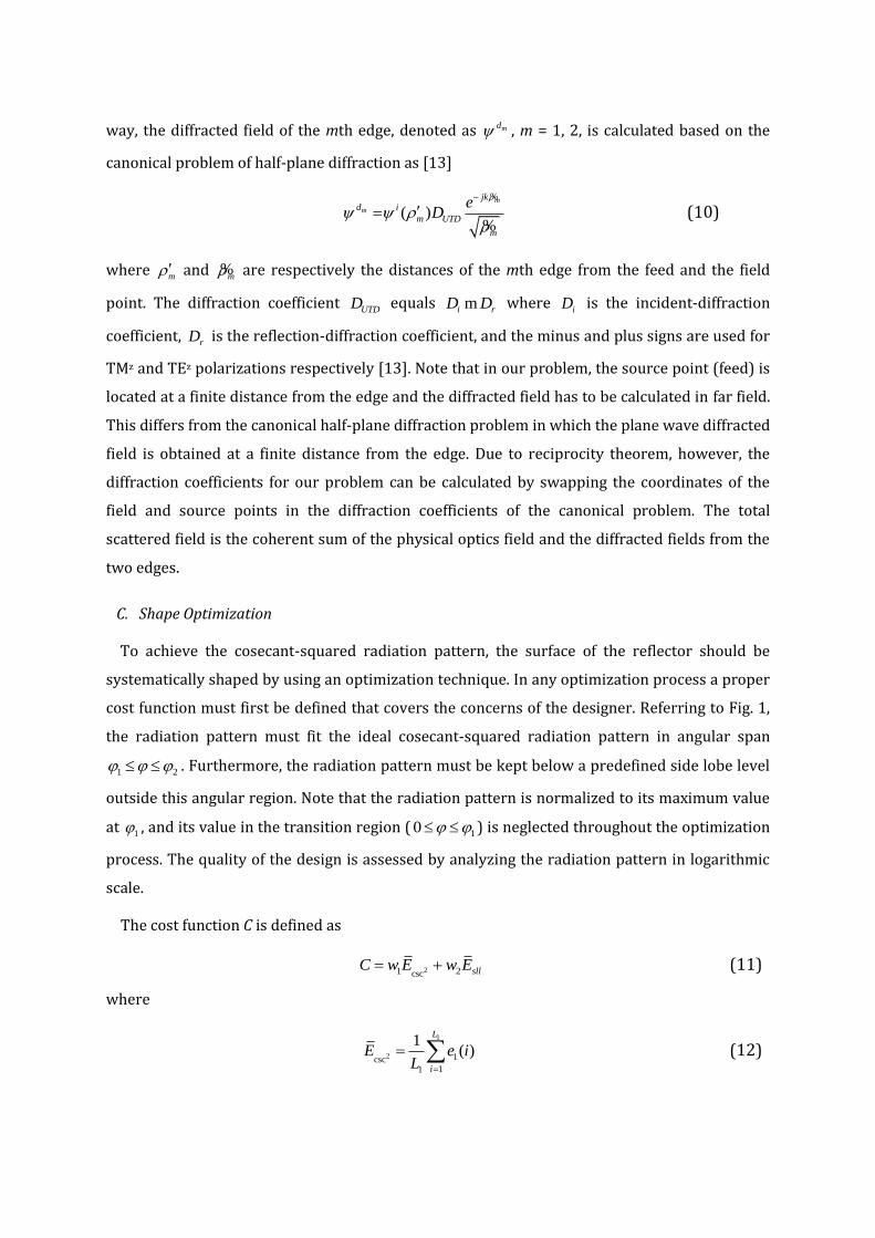
way, the diffracted field of the mth edge, denoted as md , m = 1, 2, is calculated based on the
canonical problem of half-plane diffraction as [13]
( )m
m
jkd i
m UTD
m
eD
%
% (10)
where m and
m% are respectively the distances of the mth edge from the feed and the field
point. The diffraction coefficient UTDD equals
i rD Dm where iD is the incident-diffraction
coefficient, rD is the reflection-diffraction coefficient, and the minus and plus signs are used for
TMz and TEz polarizations respectively [13]. Note that in our problem, the source point (feed) is
located at a finite distance from the edge and the diffracted field has to be calculated in far field.
This differs from the canonical half-plane diffraction problem in which the plane wave diffracted
field is obtained at a finite distance from the edge. Due to reciprocity theorem, however, the
diffraction coefficients for our problem can be calculated by swapping the coordinates of the
field and source points in the diffraction coefficients of the canonical problem. The total
scattered field is the coherent sum of the physical optics field and the diffracted fields from the
two edges.
C. Shape Optimization
To achieve the cosecant-squared radiation pattern, the surface of the reflector should be
systematically shaped by using an optimization technique. In any optimization process a proper
cost function must first be defined that covers the concerns of the designer. Referring to Fig. 1,
the radiation pattern must fit the ideal cosecant-squared radiation pattern in angular span
1 2 . Furthermore, the radiation pattern must be kept below a predefined side lobe level
outside this angular region. Note that the radiation pattern is normalized to its maximum value
at 1 , and its value in the transition region ( 10 ) is neglected throughout the optimization
process. The quality of the design is assessed by analyzing the radiation pattern in logarithmic
scale.
The cost function C is defined as
21 2csc sllC w E w E (11)
where
1
2 1csc11
1( )
L
i
E e iL
(12)
is the average difference between the obtained normalized pattern and the ideal cosecant-
squared pattern, and
2
2
12
1( )
L
sll
j
E e jL
(13)
is the average cost of exceeding the side lobe level. Specifically, 1L is the number of sampling
points in angular region 1 2 and
1( )e i is the absolute value of the logarithmic difference
between the obtained and ideal pattern at ith sampling angle. Furthermore, 2L is the number of
sampling points outside 1 2 and 2 ( )e j is defined as
2
( ) ( )( )
2
X j X je j
(14)
where X(j) is the logarithmic field level in excess of the predefined side lobe level at jth sampling
angle. Note that if the field level is less than the predefined side lobe level, 2 ( )e j will be zero, as
expected. In (11), the user-defined coefficients w1 and w2 weight the significance of the two
mentioned factors in the cost function. In order to design a dual-polarized antenna, the cost
function is simultaneously minimized for both TMz and TEz polarizations.
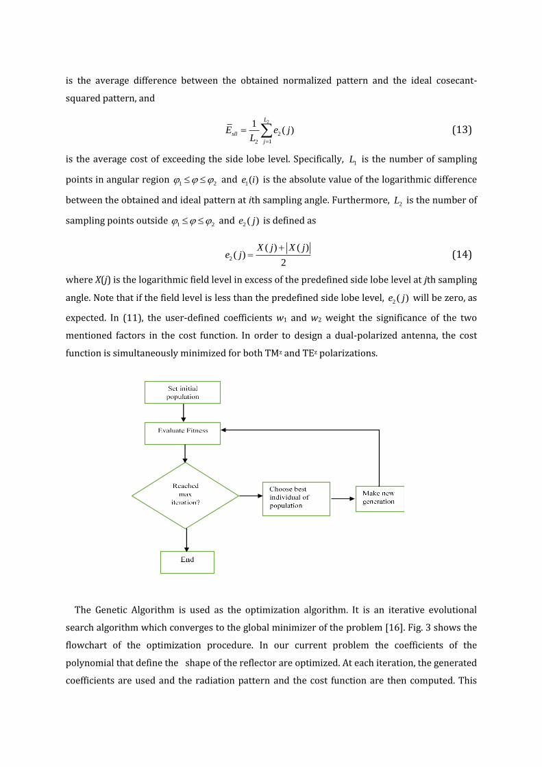
The Genetic Algorithm is used as the optimization algorithm. It is an iterative evolutional
search algorithm which converges to the global minimizer of the problem [16]. Fig. 3 shows the
flowchart of the optimization procedure. In our current problem the coefficients of the
polynomial that define the shape of the reflector are optimized. At each iteration, the generated
coefficients are used and the radiation pattern and the cost function are then computed. This

process is repeated until a predefined number of iterations is reached and the shaped reflector
with desired pattern is designed. The degree of the polynomial and the number of iterations of
the optimization process are selected according to the available computational resources and
the desired accuracy. Detailed discussion on the numerical results is presented in the next
section.
III. NUMERICAL RESULTS AND DISCUSSION
The reflector is designed to achieve the cosecant-squared radiation pattern. With reference to
Fig. 1, the values 1 23 , 50 and SLL = −25 dB are considered for the design procedure.
Extending this angular span and/or realizing lower side lobe level only increase the
computational burden, but the optimization procedure remains the same. Realizing the
cosecant-squared pattern is usually more important and computationally intensive than
reducing the side lobe level. As a result, the weighting coefficients of the cost function are
selected w1 = 2/3 and w2 = 1/3.
Large dimensions of the reflector are desirable for more radiation gain, but, on the other
hand, physical limitations due to weight and volume do not permit very large sizes. Here, the
diameter of reflector is selected d = 3 m which is 30 times the wavelength at operation
frequency of 3 GHz. To ensure blockage elimination, the offset angle is selected a few degrees
based on the size of the feed. It
Fig. 4 Convergence curve of the fitness function
is set at θoffset = 5
in our simulation assuming that a C-band horn antenna is used as the feed.
The initial geometry of the surface is chosen as a cylindrical parabolic reflector. The focal length

is fl = 2.5885 m and the corresponding polynomial coefficients with four-digit precision are
given in Table I. The offset parameter is set H = 0.226 m based on the selected offset angle and
the focal length of the reflector.
The feed points toward the center of the angular region that the initial parabolic reflector
occupies. According to the selected values of d, H, fl, the direction of maximum radiation is
computed φ0 = 145.6
. The value q in (4) is set 10 which produce -6 dB tapering at the edges of
the reflector surface.
The Genetic Algorithm (GA) is used for optimizing the polynomial coefficients of the reflector
surface. Population size of every generation in GA optimization process is empirically selected
10. Lower population sizes have been found unable to provide the optimization goals whereas
higher population sizes significantly increase the computational burden with little improvement
in the final result. The polynomial degree is selected 6, which is found to provide a good trade-
off between the accuracy of the results and the computational burden of the optimization. In
order to retain the overall shape of the offset reflector, the value of a0 is not changed and the
optimization procedure involves the rest of the polynomial coefficients. One of the members in
the initial population of GA is chosen based on Table I and setting other polynomial coefficients
to zero. At each iteration, PO and UTD are used to calculate the radiation pattern in both TMz
and TEz polarizations. The pattern described by (8), (9) are numerically calculated by using
global adaptive quadrature method. The best individual of the population with minimum value
of cost function is determined and passed to the next generation. Other members of the next
generation are generated by mutation and cross-over operations. This process is repeated until
the GA algorithm converges, the cost function is minimized and the desired
Table I. Polynomial coefficients for initial geometry of the reflector.
a0 a1 a2
−2.5885 0 0.0966
Table II. Optimized polynomial coefficients describing the surface of the reflector.
a0 a1 a2 a3 a4 a5 a6
−2.5885 −0.0101 0.0888 −0.0026 0.0016 0.0012 −0.0007

Fig. 5 The geomatry of desired shaped reflector
pattern is achieved. The convergence curve of the fitness function is shown in Fig. 4. As
observed, the convergence is achieved after 100 iterations in our simulation.
Table II shows the values of optimized polynomial coefficients. The resulting geometry of the
reflector is also depicted in Fig. 5. Note that the antenna is flat along the z-axis and Fig. 5 shows
the cross section of the synthesized antenna. The shaped reflector radiates cosecant-squared
pattern in the elevation plane as depicted in Fig. 6 for both TMz and TEz polarizations.
Two reference solutions, CST software as well as a code based on the method of moments
(generated by the authors), are used to validate the simulation results. A snapshot of the
geometry simulated by CST is depicted in Fig. 7. The developed code base on the method of
moments is the other reference solution to validate the simulation results. Since we are dealing
with an open surface, the Electric Field Integral Equation (EFIE) is solved. The surface current
density has only z component in TMz polarization whereas it has both x and y components in TEz
polarization. The point-matching technique is used to discretize the integral equation over the
reflector surface with sampling rate of 20 segments per wavelength. The surface current density
is obtained by solving the
(a) (b)
Fig. 6. The radiation pattern of the shaped reflector at 3 GHz, (a) zTE polarization, (b) zTM polarization.
-3 -2.5 -2 -1.5 -1 -0.5 00
0.5
1
1.5
2
2.5
3
3.5
x (meter)
y (
mete
r)

Fig. 7. The geometry of shaped reflector fed by a long open-ended rectangular waveguide in CST environment
Table III. characteritics of the obtained radiation pattern for low, mid and high frequencies
Frequency (GHz) 2csc
TMzE 2csc
TEzE TMz
sllE TEz
sllE ( )TMzGain dBi ( )TEzGain dBi
2.5 0.75 0.70 0.33 0.33 34.9 35
3 0.65 0.58 0.18 0.18 36.5 36.6
4 0.97 0.94 0.09 0.06 38.7 38.7
resulting linear equation system. Then, the radiation integral is calculated and the scattered
field is obtained. The results of CST and the method of moments are shown in Fig. 6 for
validation of the
designed reflector pattern. As observed, the radiation pattern of the designed reflector agrees
well with CST and the method of moments in the angular region of interest. This confirms the
validity of our field computations and optimization procedure. The CST simulation takes 40
minutes to complete on a personal computer with Intel core i7 4790 4 GHz CPU and 32GB
memory, whereas a single run of our physical optics simulation runs instantaneously. Due to the
large size of the reflector, the simulation would have been very intensive if the CST simulation
were used for field computations
(a) (b)
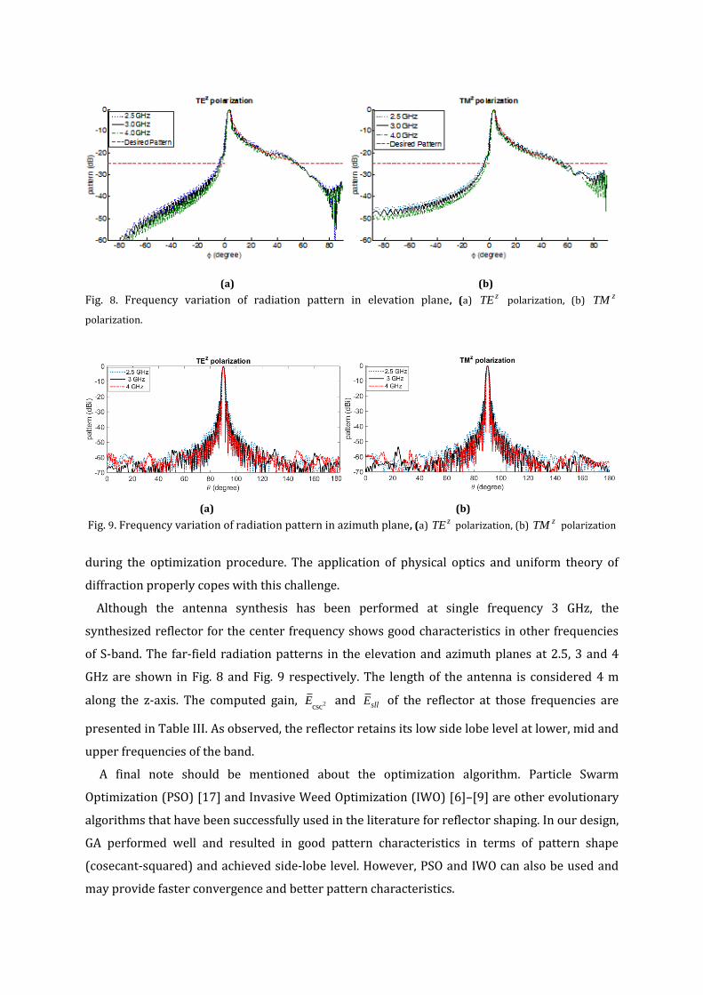
Fig. 8. Frequency variation of radiation pattern in elevation plane, (a) zTE polarization, (b) zTM
polarization.
(a) (b)
Fig. 9. Frequency variation of radiation pattern in azimuth plane, (a) zTE polarization, (b) zTM polarization
during the optimization procedure. The application of physical optics and uniform theory of
diffraction properly copes with this challenge.
Although the antenna synthesis has been performed at single frequency 3 GHz, the
synthesized reflector for the center frequency shows good characteristics in other frequencies
of S-band. The far-field radiation patterns in the elevation and azimuth planes at 2.5, 3 and 4
GHz are shown in Fig. 8 and Fig. 9 respectively. The length of the antenna is considered 4 m
along the z-axis. The computed gain, 2cscE and sllE of the reflector at those frequencies are
presented in Table III. As observed, the reflector retains its low side lobe level at lower, mid and
upper frequencies of the band.
A final note should be mentioned about the optimization algorithm. Particle Swarm
Optimization (PSO) [17] and Invasive Weed Optimization (IWO) [6]–[9] are other evolutionary
algorithms that have been successfully used in the literature for reflector shaping. In our design,
GA performed well and resulted in good pattern characteristics in terms of pattern shape
(cosecant-squared) and achieved side-lobe level. However, PSO and IWO can also be used and
may provide faster convergence and better pattern characteristics.
IV. CONCLUSION
A dual polarized cylindrical offset reflector antenna has been designed in this paper to achieve
cosecant-squared radiation pattern in S-band. In the design procedure the cross section of the
reflector has been modeled with a polynomial function of degree 6. The coefficients of the
polynomial have been initially selected as those of a cylindrical parabolic reflector. These
coefficients are then optimized by genetic algorithm to achieve cosecant-squared radiation
pattern in angular span of 3
-50
. The side lobe level of -25 dB has also been implemented in
the cost function for other elevation angles.
Utilizing the physical optics and uniform theory of diffraction has enhanced the computational
efficiency of the optimization. The large size of the antenna with respect to wavelength justifies
the application of these two asymptotic methods for calculating the radiation pattern. This is a
vital point particularly in the optimization process, since the induced current density (and
consequently the radiation pattern) can be efficiently calculated for a large population size in
each iteration of the optimization.
The numerical results show that desired characteristics of the radiation pattern can be
achieved with good accuracy for both TE and TM polarizations. The calculated radiation pattern
deviates about or less than 0.8 dB on average from the ideal cosecant-squared pattern.
Furthermore, the side lobe level is kept below -25 dB out of the angular range of main beam. To
ensure the validity of the results, the radiation pattern of the optimized antenna has been
calculated with CST software as well as the method of moments, which agree quite well with the
PO-UTD results. Therefore, the procedure presented in this paper can be used to accurately and
efficiently design the cylindrical reflector for achieving the cosecant-squared radiation pattern.
REFERENCES
[1] M. I. Skolnik, Introduction to Radar Systems, 3 ed., New York, NY: McGraw Hill, 2001.
[2] J. R. Bergmann, F. J. V. Hasselmann, L. C. P. Pereira and M. G. Castello Branco, “Reflector antenna configurations for
radio base stations in cellular communications,” IEEE-APS Conference on Antennas and Propagation for Wireless
Communications (Cat. No.98EX184), Waltham, MA, 1998, pp. 61-64.
[3] M. Koubeissi, L. Freytag, C. Decroze and T. Monediere, “Design of a Cosecant-Squared Pattern Antenna Fed by a
New Butler Matrix Topology for Base Station at 42 GHz,” IEEE Antennas and Wireless Propagation Letters, vol. 7,
pp. 354-357, 2008.
[4] N. Herscovici, “A simple cosec2 microstrip array: the shovel-microstrip array,” IEEE Antennas and Propagation
Magazine, vol. 35, no. 4, pp. 42-44, Aug. 1993.
[5] A. Haddadi, A. Ghorbani and J. Rashed-Mohassel, “Cosecant-squared pattern synthesis using a weighted
alternating reverse projection method,” IET Microwaves, Antennas & Propagation, vol. 5, no. 15, pp. 1789-1795,
Dec. 2011.

[6] A. Dastranj, H. Abiri, and A. Mallahzadeh, “Two-dimensional synthesis and optimization of a broadband shaped
beam reflector antenna using IWO and PSO algorithms,” RF and Microwave Computer-Aided Engineering, vol. 25,
no. 2, pp. 129-140, June 2014.
[7] A. Dastranj, H. Abiri, and A. Mallahzadeh, “Design of a Broadband Cosecant Squared Pattern Reflector Antenna
Using IWO Algorithm,” IEEE Transactions on Antennas and Propagation, vol. 61, no. 7, pp. 3895-3900, July 2013.
[8]A. Foudazi, and A. R. Mallahzadeh, “Pattern synthesis for multi-feed reflector antenna using invasive weed
optimization algorithm,” IET Microwaves, Antennas & Propagation, vol. 6, no. 14, pp. 1583-1589, Nov. 2012.
[9] A. A. Dastranj, H. Abiri,and A. R. Mallahzadeh, “Cosecant-squared pattern synthesis method for broadband-shaped
reflector antennas,” IET Microwaves, Antennas & Propagation, vol. 8, no. 5, pp. 328-336, April 2014.
[10] O. M. Bucci, A. Capozzoli, and G. D’Elia, “An effective power synthesis technique for shaped, double-reflector
multifeed antennas,” Progress in Electromagnetics Research, vol. 39, pp. 93-123, 2003.
[11] F. S. Adana, O. Gutierrez, I. Gonzalez, M. F. Catedra, L. Lozano, Practical Applications of Asymptotic Techniques in
Electromagnetics, Norwood, MA: Artech House, 2011.
[12] D. Dah-Weihand, Y.Rahmat Samii, “A generalized diffraction synthesis technique for high performance reflector
antennas,” IEEE Transactions on Antennas and Propagation, vol. 43, no. 1, pp. 27-40, Jan 1995.
[13] C. A. Balanis, Advanced Engineering Electromagnetics, 2nd ed., Hoboken, NJ: Wiley, 2012.
[14] C. A. Balanis, Antenna Theory: Analysis and Design, 4th ed., Hoboken, NJ: Wiley, 2016.
[15] A. S. Glassner, An Introduction to Ray Tracing, London, UK: Academic Press, 1989.
[16] D. E. Goldberg, Genetic Algorithms in Search, Optimization, and Machine Learning, Reading, MA: Addison-Wesley,
1989.
[17] J. Robinson and Y. Rahmat-Samii, “Particle swarm optimization in electromagnetics,” IEEE Transactions on
Antennas and Propagation, vol. 52, no.2, pp. 397-407, Feb. 2004.