due to the process of continuous improvement, the ... - freedom...
TRANSCRIPT

1
DUE TO THE PROCESS OF CONTINUOUS IMPROVEMENT, THE PRODUCTS AND PROCEDURES IN THIS MANUAL ARE
SUBJECT TO CHANGE WITHOUT NOTICE
Part #H8201

2
TABLE OF CONTENTS
TABLE OF CONTENTS.................................................................................................. 2
1.0 GENERAL INFORMATION.................................................................................. 31.1 Receiving Materials & Filing Claims.................................................................................31.2 Handling Materials............................................................................................................41.3 Storing Materials............................................................................................................... 51.4 Lifting/Handling Panels.....................................................................................................61.5 Placing Panel Bundles on the Roof..................................................................................71.6 How To Use This Manual .................................................................................................81.7 Proper Fastener Installation .............................................................................................91.8 Panel Preparation...........................................................................................................101.9 Safety First .....................................................................................................................11
2.0 FASTENERS AND MASTICS REQ’D FOR INSTALLATION............................ 122.1 General........................................................................................................................... 12
3.0 INSTALLATION OF CLASSIC ROOF ............................................................... 143.1 Starting Layout ...............................................................................................................143.2 Mastic Installation Tips ...................................................................................................153.3 Insulation ........................................................................................................................163.4 Sculptured Eave Trim.....................................................................................................173.5 Panel/Fastener Diagram ................................................................................................183.6 Start/Finish Dimensions .................................................................................................193.7 Panel Erection at Low Eave ...........................................................................................203.8 Panel Erection at Side Lap.............................................................................................213.9 Panel Splice Detail .........................................................................................................223.10 Die-Formed Ridge Cap Installation ................................................................................23
4.0 TRIM INSTALLATION ....................................................................................... 244.1 Trim Lap Details for Gutter, Rake, and Rake Parapet Trim ...........................................254.2 Trim Lap Details for High Eave & High Eave Parapet Trim ...........................................264.3 Low Eave Flash..............................................................................................................274.4 Rake Trim at Corner Without Gutter............................................................................... 284.5 Gutter and Gutter Bracket Installation............................................................................294.6 Rake Trim at Corner With Gutter (Outside Corner)........................................................304.7 Rake Trim Installation.....................................................................................................314.8 Rake Trim Termination at High Eave or Ridge .............................................................324.9 Peak Box Installation at Ridge Cap................................................................................334.10 Press-Broke Ridge Cap Installation at Peak Box...........................................................344.11 Press-Broke Ridge Cap Lap Detail ................................................................................354.12 High Eave Trim Installation ............................................................................................364.13 Rake Parapet Trim Installation, With and Without Gutter .............................................. 374.14 Rake Parapet Trim Termination at Die-Formed Ridge Cap........................................... 384.15 Rake Parapet Trim Termination at Press-Broke Ridge Cap ..........................................394.16 High Eave Parapet Trim Installation...............................................................................40

3
1.0 GENERAL INFORMATION
1.1 RECEIVING MATERIALS & FILING CLAIMS
Check shipment against delivery tickets during unloading.
Note any damage or discrepancies on the delivery tickets before signing as receiver.
Metal Building Supplier is not responsible for carrier damage or discrepancies not noted on the delivery tickets.
Metal Building Supplier is not responsible for items accepted in questionable condition.
Upon acceptance of shipment(s), the contractor is responsible for the proper storage and handling of materials as described in this manual.
Metal Building Supplier is not responsible for injury, damage, or loss as a result of improper storage and/or handling.
All claims must be filed with Metal Building Supplier’s Quality Services Representative prior to any field modifications or purchases that may result in a charge to Metal Building Supplier.
This building is designed, manufactured, and delivered in accordance with the 2006 LOW RISE BUILDING SYSTEMS MANUAL as published by M.B.M.A.. Consult the information in the “COMMON INDUSTRY PRACTICES” section.
4
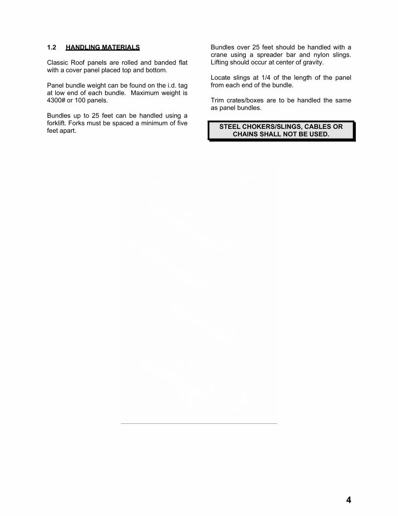
1.2 HANDLING MATERIALS
Classic Roof panels are rolled and banded flat with a cover panel placed top and bottom.
Panel bundle weight can be found on the i.d. tag at low end of each bundle. Maximum weight is 4300# or 100 panels.
Bundles up to 25 feet can be handled using a forklift. Forks must be spaced a minimum of five feet apart.
Bundles over 25 feet should be handled with a crane using a spreader bar and nylon slings. Lifting should occur at center of gravity.
Locate slings at 1/4 of the length of the panel from each end of the bundle.
Trim crates/boxes are to be handled the same as panel bundles.
STEEL CHOKERS/SLINGS, CABLES OR CHAINS SHALL NOT BE USED.

5
1.3 STORING MATERIALS
Panel and trim bundles / crates should be blocked 12 inches above grade.
Elevate one end to allow moisture to drain.
Loosely cover with waterproof tarp to allow proper air circulation.
Inspect daily and dry if necessary.
Accessories must be kept dry and free of contamination. Store indoors if possible.

6
1.4 LIFTING/HANDLING PANELS
Lift and handle bundles as described earlier. Do not use any type of steel or cable slings.
Lift or carry single panels in a vertical position so as not to damage the seams.
Lift the panels at 1/4 points.

7
1.5 PLACING PANEL BUNDLES ON THE ROOF
Locate bundles on roof according to erection sequence.
Bundles should be located over primary structural frame lines, not in the middle of the bay.
Blocking shall be used, as shown, at panel bundle locations.
Purlin
Blocking (Not by MBS)
Primary Frame Rafter
Bundles Should be located over the Primary Frames

8
1.6 HOW TO USE THIS MANUAL
This erection manual is provided as the recommended procedure for the correct assembly of the Metal Building Supplier (MBS) Classic Roof System.
This manual is intended to be used in conjunction with the project’s erection drawings to help plan and organize the installation of the (MBS) Classic Roof System. The erection drawings identify the applicable roof conditions and govern specific part arrangements. The instructions will help you identify parts, establish the installation sequence, demonstrate correct assembly, and point out any areas or procedures requiring special emphasis or attention. Before beginning erection, thoroughly familiarize yourself with this manual and project erection drawings.
The procedures contained in this manual are based upon standard conditions. If your project contains other than standard conditions, refer to your project erection drawings. In the case of conflict between this installation manual and the erection drawings, the erection drawings will take precedence.
The procedures contained in this manual are believed to be reliable however, Metal Building Supplier is not responsible for injury, damage, or failure due to the misapplication of these procedures, improper erection techniques, or negligence.
DUE TO THE PROCESS OF CONTINUOUS IMPROVEMENT, THE PRODUCTS AND PROCEDURES CONTAINED IN THIS MANUAL ARE SUBJECT TO CHANGE WITHOUT NOTICE.
“COMMON SENSE RULES” NEED TO BE APPLIED DURING THE
INSTALLATION OF THIS ROOF SYSTEM TO INSURE THAT
WEATHER-TIGHT CONDITIONS HAVE BEEN ACHIEVED.
The (MBS) Classic Roof System can be erected on many different types of construction. However, for this manual we have assumed this roof system will be erected on a new pre-engineered metal building.

9
1.7 PROPER FASTENER INSTALLATION
Refer to section 2.0 or the project erection drawings for fastener schedule
RECOMMENDED TOOL TYPES:
2000 - 2500 rpm screw gun with torque adjustable clutch
Manual or electric rivet tool 6-7 amp or higher rated tools
DO NOT USE IMPACTING TOOLS
To assure proper voltage to the tool, extension cords should be checked for proper wire size/chord length.
- 16 gage wire, maximum chord length = 100’
- 14 gage wire, maximum chord length = 200’
- 12 gage wire, maximum chord length = 300’
DRIVING TIPS:
Drive fasteners perpendicular to panel surface.
Compress the insulation at fastener locations with one hand while driving the fastener with the other. This will help keep the panel flat and prevent the fastener from “walking”.
Excessive pressure can cause drill point failure. Let the fastener do the work.
Sealing Material slightly visible around Metal Washer
Sealing Material not visible around Metal Washer
Sealing Material deformed beyond the edge of the Metal Washer
CORRECT TOO LOOSE TOO TIGHT

10
1.8 PANEL PREPARATION
(MBS) RECOMMENDS PRE-DRILLING SIDELAP JOINTS, WHICH IN MANY CASES, WILL SPEED ERECTION AND MAKE A TIGHT JOINT.
STEP 1: Stack the panels with the ends flush on a level place on the ground in piles not exceeding 10 panels. Then place small wooden blocks under the side lapping edge of the stack of the panels to hold them at the correct height and position while drilling the screw holes. Hold the panels tightly together at each end with “Vise Grip Pliers”. Carefully mark the positions for sidelap fasteners on the top of the HIGH rib. Fasteners should be located “ON CENTER” of the high rib as shown below.
STEP 2: Drill holes for “Stitch” screws (Use #1,-7/32”-15/64” drill-bit) on the top sheet of the sidelap. Be sure that the panels are well nested before drilling.
WHEN USING OTHER TYPE FASTENERS, SIZE OF DRILL-BIT MAY CHANGE!
11
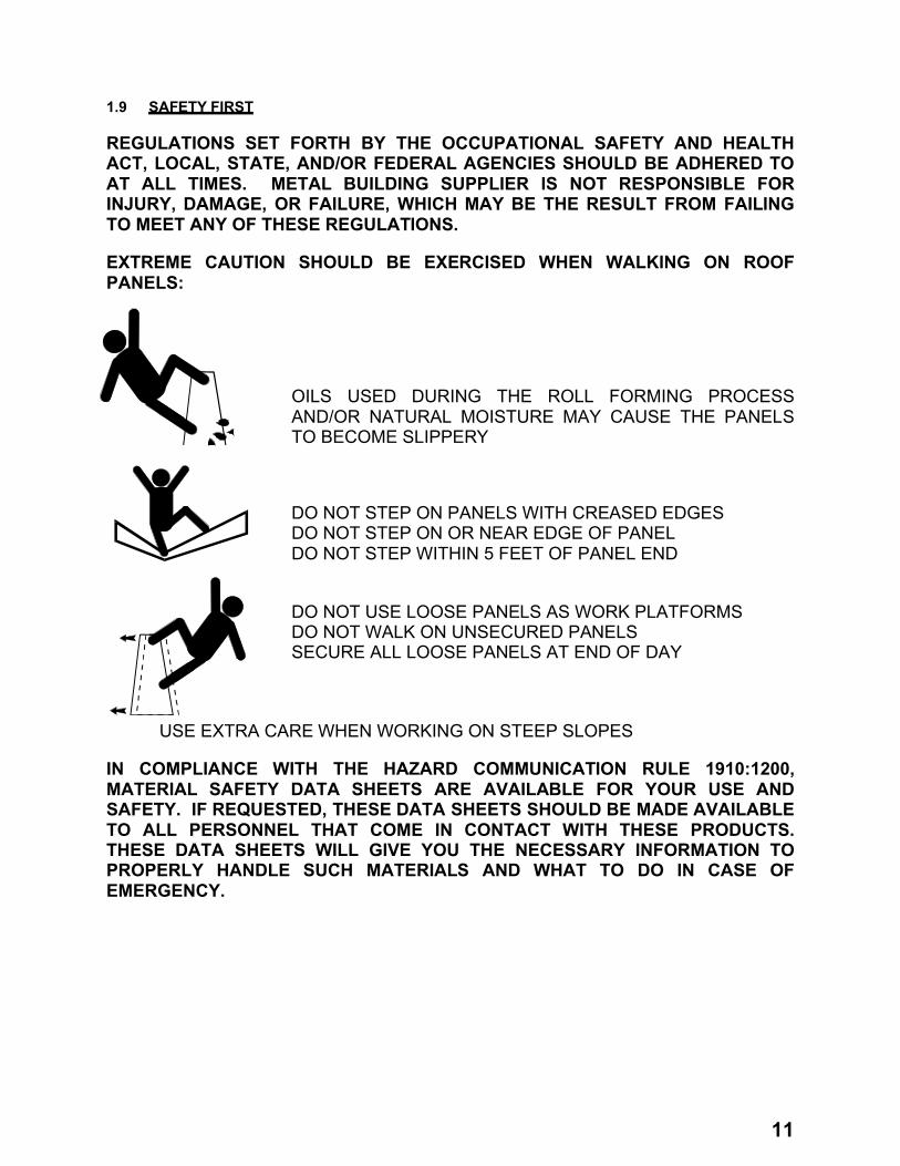
1.9 SAFETY FIRST
REGULATIONS SET FORTH BY THE OCCUPATIONAL SAFETY AND HEALTH ACT, LOCAL, STATE, AND/OR FEDERAL AGENCIES SHOULD BE ADHERED TO AT ALL TIMES. METAL BUILDING SUPPLIER IS NOT RESPONSIBLE FOR INJURY, DAMAGE, OR FAILURE, WHICH MAY BE THE RESULT FROM FAILING TO MEET ANY OF THESE REGULATIONS.
EXTREME CAUTION SHOULD BE EXERCISED WHEN WALKING ON ROOF PANELS:
OILS USED DURING THE ROLL FORMING PROCESS AND/OR NATURAL MOISTURE MAY CAUSE THE PANELS TO BECOME SLIPPERY
DO NOT STEP ON PANELS WITH CREASED EDGES DO NOT STEP ON OR NEAR EDGE OF PANEL DO NOT STEP WITHIN 5 FEET OF PANEL END
DO NOT USE LOOSE PANELS AS WORK PLATFORMS DO NOT WALK ON UNSECURED PANELS SECURE ALL LOOSE PANELS AT END OF DAY
USE EXTRA CARE WHEN WORKING ON STEEP SLOPES
IN COMPLIANCE WITH THE HAZARD COMMUNICATION RULE 1910:1200, MATERIAL SAFETY DATA SHEETS ARE AVAILABLE FOR YOUR USE AND SAFETY. IF REQUESTED, THESE DATA SHEETS SHOULD BE MADE AVAILABLE TO ALL PERSONNEL THAT COME IN CONTACT WITH THESE PRODUCTS. THESE DATA SHEETS WILL GIVE YOU THE NECESSARY INFORMATION TO PROPERLY HANDLE SUCH MATERIALS AND WHAT TO DO IN CASE OF EMERGENCY.

12
2.0 FASTENERS AND MASTICS REQ’D FOR INSTALLATION
2.1 GENERAL
This page and the following page show the fasteners, mastics, and tube caulks required for installation of the (MBS) Classic Roof System.
Because of the many variations in job conditions, it is important that you review the job conditions to identify the required parts for your job.
Review the erection drawings for any special parts, or parts that are different from what is shown in this section. If there are discrepancies, the erection drawings will take precedence.
For proper sealing and fastening, and to help ensure proper roof performance, the correct parts must be used. Do not use parts other than those specified in this manual or on the erection drawings.
FASTENER SPECIFICATIONS USAGE
-4 Amp or Higher Rated Tools-DO NOT use Impacting Tools
SELF-DRILLING SCREW
Recommended Tool Types:
-DO NOT use Impacting Tools
Recommended Tool Types:
SELF-DRILLING SCREW
-DO NOT use Impacting Tools
Recommended Tool Types:
SELF-TAPPING SCREW
SELF-TAPPING SCREW
Recommended Tool Types:
-DO NOT use Impacting Tools
Recommended Tool Types:
-DO NOT use Impacting Tools-Manual or Electric Rivet Tool
POP RIVET
SELF-DRILLING SCREW
Recommended Tool Types:
-DO NOT use Impacting Tools

13

14
3.0 INSTALLATION OF CLASSIC ROOF
3.1 STARTING LAYOUT
The roof panels are designed to, and will lay left to right or right to left.
Panel installation must begin at the low eave corner and be sequenced as shown.
Both sides of the ridge should be erected simultaneously to ensure proper alignment of panel ribs and positioning of the die-formed ridge cap.
ERECTOR NOTE: SOME DETAILS CONTAINED WITHIN THIS MANUAL SHOW CONDITION AS THOUGH THE PANELS ARE BEING ERECTED FROM LEFT-TO–RIGHT. THE PANELS CAN ALSO BE ERECTED FROM RIGHT-TO-LEFT, AND THE CONDITIONS ARE SIMILAR TO THE POINT THAT THE SAME DETAILS CAN BE UTILIZED WITHOUT ANY PROBLEMS.
WARNING: PENCIL LEAD AND MARKER WILL CAUSE GALVALUME PANELS AND TRIM PIECES TO RUST. DO NOT USE THESE TO MARK ON PARTS.
1
3
5
7
2
6
Low EaveFull Panels
Start Panels (may or may not need to be field cut-check the erection drawing roof sheeting plan and details)
4
Ridge
NOTE: Both sides of the ridge should be erected simutaneously to ensure both proper alignment of panels and positioning of the DIE-FORMED ridge cap.

15
3.2 MASTIC INSTALLATION TIPS
Apply the tape mastic only to clean dry surfaces.
Roll the mastic out to arm length.
Press the mastic firmly in place making sure it is tightly formed to all bends.
Remove the paper backing only when ready to install the top component.
Splice the mastic with a 2” lap.
Press the lapped pieces of mastic firmly together to form a single thickness.
DO NOT STRETCH TAPE MASTIC ACROSS THE CORNERS. THIS WILL DECREASE THE THICKNESS WHERE IT IS NEEDED THE MOST.
2"
WRONG WAY RIGHT WAYVoid
Tape MasticRoof Panel
LapPaper BackingTape Mastic Compress to
One Thickness
Mastic formed tight to bends
TapeMastic

16
3.3 INSULATION
Install the (optional) insulation pan at the ridge, if required, prior to any roof panel installation. Do not attach at this time, the insulation screws will make the attachment. DO NOT USE INSULATION PAN AS A WORK PLATFORM.
Align the edge of the insulation with the building endwall steel line.
Pull the insulation toward the ridge / high eave so as to create a smooth appearance of the backing.
Consult the insulation manufacturer installation instructions for proper seaming and taping methods.
At the low eave, remove a 4” strip of insulation from the backing leaving a 4” strip of backing exposed.
Fold this strip of backing over the insulation batt creating a double vapor barrier.
4"
DoubleVapor Barrier
Fill Eave Strut void with Insulation
Eave Strut
Insulation
Eave Strut
Insulation

17
3.4 SCULPTURED EAVE TRIM
If your building has sculptured eave trim, thecap trim must be installed prior to the installation of roof insulation and roof panels.
After the eave member has been installed, place the cap trim (CTA__) flush with the end of the eave member. Use the overhang dimensions per the roof slope noted in the following detail, then fasten with (1) self-drilling screw (H1020)at each end.
When using masonry wall or open wall conditions, use the following dimensions from face of masonry or steel line:
1 ¾” @ .5:12 2 ¼” @ 1:12 2 7/8” @ 2:12 3 5/16” @ 3:12 3 13/16” @ 4:12
See the erection drawing details for sculptured eave trim installation instructions.
Eave Angle MK. MAF__(Fasten to the Eave Purlin with (1) H1020 at Each End)
NOTE: See the Erection Drawing Roof Line Trim Details for Sculptured Eave Trim Installation Instructions

18
3.5 PANEL/FASTENER DIAGRAM
REFER TO THE PROJECT ERECTION DRAWING SHEETING DETAIL SHEETS FOR THE SIDE LAP
FASTENER SPACING REQUIRED FOR THIS PROJECT

19
3.6 START/FINISH DIMENSIONS
IMPORTANT! Note the minimum and maximum panel rib locations from the steel line. (Condition “A” and condition “B”)
Condition “A” and “B” could occur at either thestart or the finish end. These rib locations must
be maintained for the rake trim to fit properly. Field cutting of panel(s) may be required.
Refer to your project erection drawings “ROOF SHEETING PLAN” for specific start and finish panel rib locations.
Rake Angle (At Steel Line)
Centerline of Panel RibSteel Line 1/2" Min., 2 7/8" Max.
CONDITION "A"
CONDITION "B"
Steel Line
Roof Panel
Rake Angle (At Steel Line)
Centerline ofPanel Rib
8 3/8" Min.
Field Cut Panel
Roof Panel
Rake Trim
Rake Trim
Wall Panel
Wall Panel

20
3.7 PANEL ERECTION AT LOW EAVE
Apply 3/4” tape mastic (H3000) to the top & bottom of the insulation vapor barrier, the full length of the roof.
Position the inside rubber closure (H3410) directly over the mastic and apply 3/4” tape mastic (H3000) to the top side of the closure.
Check your project erection drawings for proper roof panel start and overhang dimensions. Install a string line 1” from the end of the panel to help ensure proper panel installation.
Position the roof panel over the closure and set in place. NOTE: The panel must be properly positioned before touching the mastic. Mastic cannot be reused.
STD. EAVE DETAILNOTE: Verify the Roof Panel Overhang Dimension with the Erection Drawing Details
Inside Panel Closure with 3/4" Tape Mastic Top and Bottom
Steel Line
Roof Panel
Eave StrutWall Panel
Cap Trim
5 1/4"
Vapor Barrier
Double-Faced Tape NOT BY M.B.S. (Use to hold insulation down before roof panel is installed)
Eave Strut
Insulation
Inside Panel Closure
Roof Panel
3/4" Tape Mastic
3/4" Tape Mastic
3/4" Tape Mastic
1"
Install a String Line 1" from the end of the panels to help ensure proper panel installation.
21
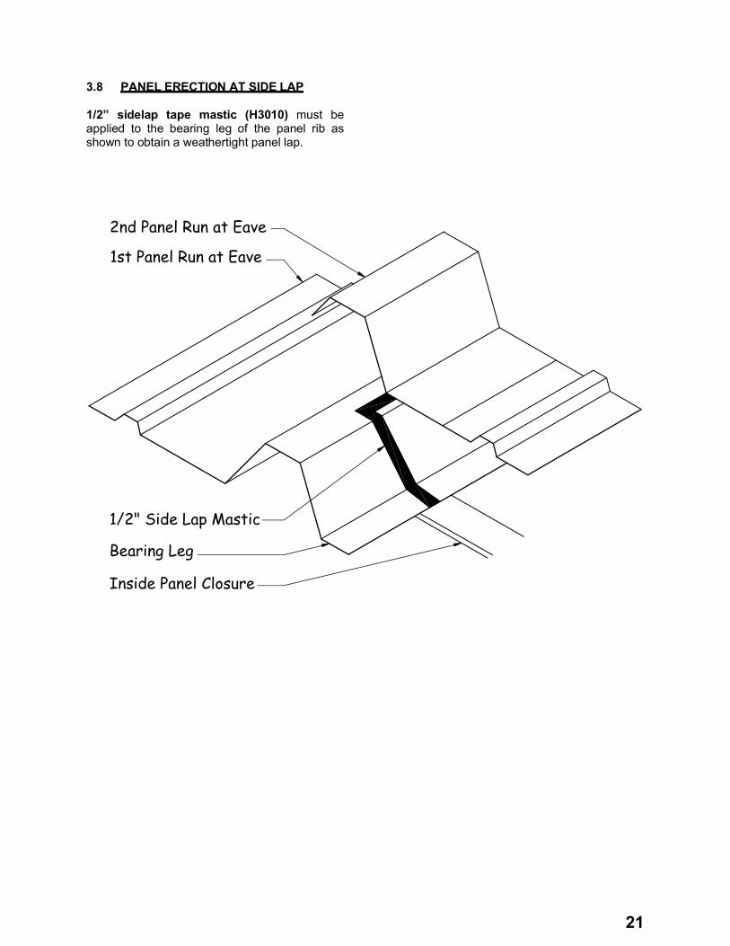
3.8 PANEL ERECTION AT SIDE LAP
1/2” sidelap tape mastic (H3010) must be applied to the bearing leg of the panel rib as shown to obtain a weathertight panel lap.
1st Panel Run at Eave
2nd Panel Run at Eave
Bearing Leg
1/2" Side Lap Mastic
Inside Panel Closure
22
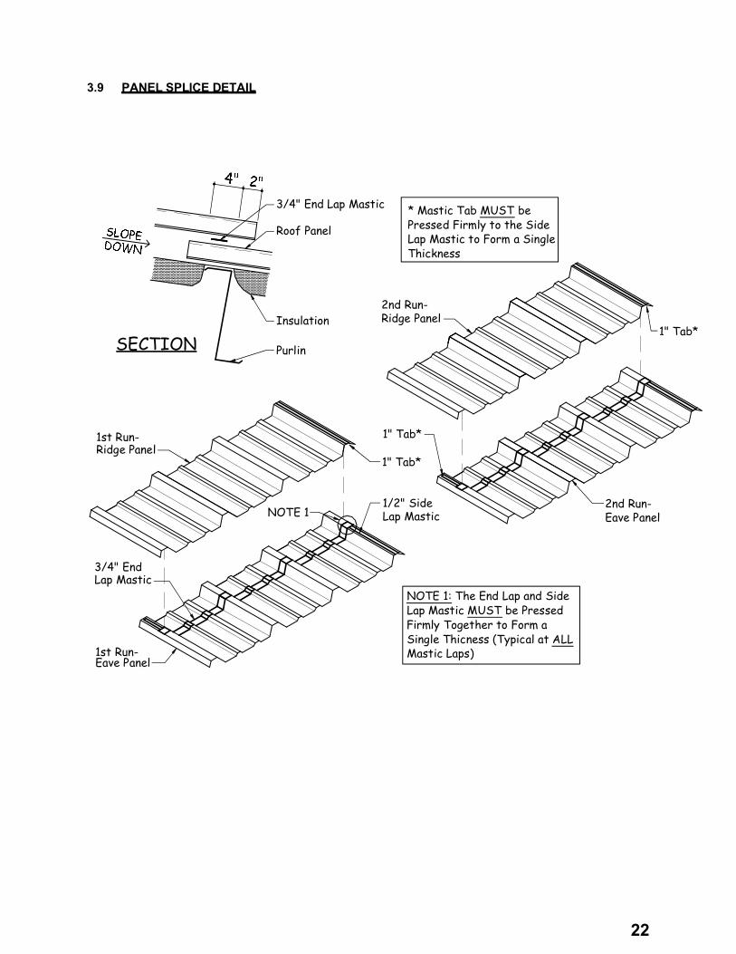
3.9 PANEL SPLICE DETAIL
2nd Run-
1" Tab*
2nd Run-
1" Tab*
1st Run-
1st Run-
1" Tab*
NOTE 11/2" Side
3/4" End
SECTION
3/4" End Lap Mastic
Roof Panel
Insulation
Purlin
* Mastic Tab MUST be Pressed Firmly to the Side Lap Mastic to Form a Single Thickness
NOTE 1: The End Lap and Side Lap Mastic MUST be Pressed Firmly Together to Form a Single Thicness (Typical at ALL Mastic Laps)
Lap Mastic
Ridge Panel
Ridge Panel
Lap Mastic
Eave Panel
Eave Panel

23
3.10 DIE-FORMED RIDGE CAP INSTALLATION
IMPORTANT NOTE: The panel ribs MUST be aligned across the ridge for proper fit-up of the die-formed ridge cap.
Fasten the ridge cap side laps with (6) self-tapping screws (H1050).
See the fastener diagram in section 3.5, or your project erection drawings for proper fastener placement.
If your roof has press-broke ridge cap, go to section 4.11 for installation instructions
Ridge Cap
Side Lap Mastic
Ridge Cap
DETAIL
3/4" Tape Mastic(Continuous)
Die-Formed Ridge Cap
1/2" Side Lap Mastic
Ridge Purlin
Roof Panel SEE
BELOW
NOTE: Insulation not shown for Clarity
RIDGE CAP LAP MASTIC DETAIL

24
4.0 TRIM INSTALLATION
Begin installing trim at the back of the building working toward the front. This will “hide” the trim laps from direct view.
When lapping rake trim and rake parapet trim, the upper piece should overlap the lower piece. This will help prevent water from entering the building.
Panel cap trim (CTA__) must be installed prior to the installation of the low eave trim (see the detail below).
Some field cutting, trimming, and bending is required. Extreme care must be taken while performing any fieldwork so as to produce an attractive, weathertight condition.
NOTE: The wall panel (or whatever material is being on the walls) will need to be installed before the roof line trim can be installed.
The parts shown in the following sections are the “standard” trim profiles. It is a good idea to compare the part numbers in this manual with the erection drawing roof line trim details to verify the correct part numbers. In the case of conflict, the erection drawings will take precedence.
Inside Panel Closure with 3/4" Tape Mastic Top and Bottom
STD. SCULPTURED EAVE DETAIL
STD. EAVE DETAILNOTE: Verify the Roof Panel Overhang Dimension with the Erection Drawing Details
Inside Panel Closure with 3/4" Tape Mastic Top and Bottom
Steel Line
Roof Panel
Eave StrutWall Panel
CAP TRIM
5 1/4"
NOTE: Verify the Roof Panel Overhang Dimension with the Erection Drawing Details
Steel Line 7 1/4"
Roof Panel
Wall PanelEave Strut
CAP TRIM

25
4.1 TRIM LAP DETAILS FOR GUTTER, RAKE, AND RAKE PARAPET TRIM
GUTTER: Apply a continuous bead of polyurethane tube caulk (H3152) to the end of adjoining trim piece, lap 1”, and fasten with 10 pop rivets (H1100).
RAKE TRIM: Apply a continuous bead of polyurethane tube caulk (H3152) to the end of the adjoining trim piece and lap 1”. Fasten with (5) trim-colored self-tapping screws and (5)
pop rivets (H1100). Always begin trim installation at the low eave working toward the high eave.
RAKE PARAPET TRIM: Apply a continuous bead of polyurethane tube caulk (H3152) to the end of the adjoining trim piece, lap 1” and fasten with (4) self-tapping screws (H1050)and (2) pop rivets (H1100).
.
= Pop Rivet
(4 at Bottom)Pop Rivets
Polyurethane
= Fastener
GUTTER
RAKE TRIM
RAKEPARAPET TRIM
Tube Caulk
Tube CaulkPolyurethane
PolyurethaneTube Caulk

26
4.2 TRIM LAP DETAILS FOR HIGH EAVE & HIGH EAVE PARAPET TRIM
HIGH EAVE TRIM: Apply a continuous bead of polyurethane tube caulk (H3152) to the end of adjoining trim piece, lap 1” and fasten with (4) self-tapping screws (H1050) and (4) pop rivets.
HIGH EAVE PARAPET TRIM: Apply a continuous piece of 3/4” tape mastic (H3000) at the end of the installed trim piece. Position the adjoining trim piece on the top of the mastic and fasten with (7) self-tapping screws (H1050).
Apply a bead of polyurethane tube caulk (H3152) on top of the mastic.
SCULPTURED EAVE TRIM:
See erection drawing details for installation instructions.
27
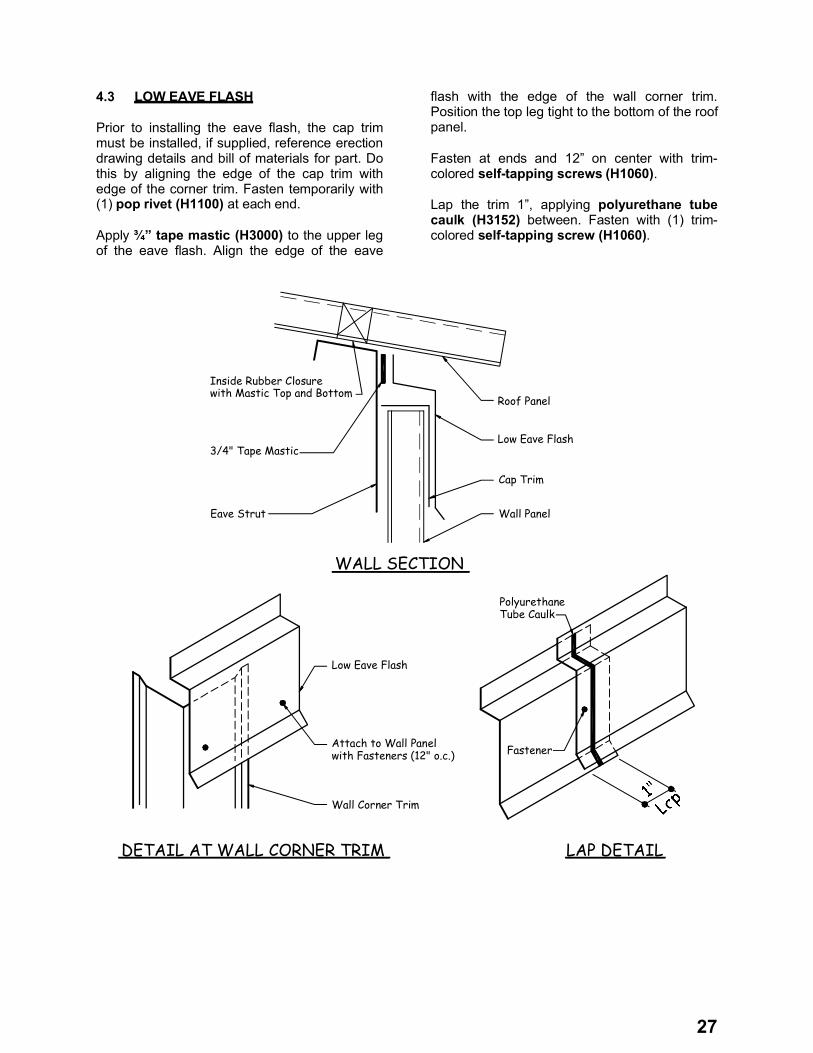
4.3 LOW EAVE FLASH
Prior to installing the eave flash, the cap trim must be installed, if supplied, reference erection drawing details and bill of materials for part. Do this by aligning the edge of the cap trim with edge of the corner trim. Fasten temporarily with (1) pop rivet (H1100) at each end.
Apply ¾” tape mastic (H3000) to the upper leg of the eave flash. Align the edge of the eave
flash with the edge of the wall corner trim. Position the top leg tight to the bottom of the roof panel.
Fasten at ends and 12” on center with trim-colored self-tapping screws (H1060).
Lap the trim 1”, applying polyurethane tube caulk (H3152) between. Fasten with (1) trim-colored self-tapping screw (H1060).
WALL SECTION
Low Eave Flash
Cap Trim
LAP DETAIL
Polyurethane
3/4" Tape Mastic
Wall PanelEave Strut
Roof Panel
Inside Rubber Closure
Low Eave Flash
with Fasteners (12" o.c.)
Wall Corner Trim
DETAIL AT WALL CORNER TRIM
Attach to Wall Panel Fastener
Tube Caulk
with Mastic Top and Bottom

28
4.4 RAKE TRIM AT CORNER WITHOUT GUTTER
RAKE TRIM PART NUMBERSRTA01 x 10’-1” RTA02 x 20’-2”
All parts must be positioned properly before touching the mastic to the roof panel. Mastic cannot be reused!
Before installing the rake trim, the rake cap (RCA__) must be installed and the gutter end cap (H4000) prepped. For the rake cap, apply polyurethane tube caulk (H3152) to the top and bottom surfaces and place it on the edge of the panel 1 ½” from the edge of the gutter end cap (no fasteners required). Field cope the flat of the rake cap as required. Prep the gutter end cap by placing the eave/rake cap (ERA01) onto the back of the cap and fasten with (6) pop rivets (H1100) as shown below.
Apply continuous 2 ¼” tape mastic (H3020) to the bottom of the horizontal leg of the rake trim (the leg that attaches to the roof panel).
Extend the low eave end of the rake trim flush with the low eave end of the roof panel. Fasten the rake trim to the roof panel with trim colored self-drilling screws (H1030) at 4” o/c. Fasten the rake trim to the rake cap with (4) trim colored self-tapping screws (H1050) and (2) pop rivets (H1100). Cope the bottom vertical leg of the rake trim flush with the outside face of the wall corner trim.
For the installation of the prepped gutter end cap (H4000), apply polyurethane tube caulk (H3152) to the outside perimeter (as shown below) and place it inside the rake trim with the flat edge of the gutter end cap flush with the end of the rake trim. Fasten the rake trim to the gutter end cap with (3) pop rivets (H1100).

29
4.5 GUTTER AND GUTTER BRACKET INSTALLATION
Establish a string line 7” from end of the roof panel for proper gutter bracket alignment.
Apply 6” long tape mastic (H3000) to the end of the gutter bracket (H2190) directly under the pre-punched holes.
Fasten the bracket to the panel HIGH rib with (2) gutter bracket-colored self-tapping screws(H1050).
Apply 1/2” tape mastic (H3010) to the back lip of the gutter and then fasten the gutter to the roof panel with roof-colored self-tapping screws (H1050) at 12” on center. NOTE:Clamping the gutter to the roof panel will allow for easier gutter installation.
Attach the gutter to the bracket with (1) trim-colored self-tapping screw (H1050).
NOTE: The gutter bracket should be UNDERthe lip of the gutter.
1/2" Tape Mastic Between Gutter and Roof Panel
Gutter
Roof Panel
7" Precut Mastic Between Bracket and Roof Panel
GutterBracket
Fastener (Typical 3 places)

30
4.6 RAKE TRIM AT CORNER WITH GUTTER (OUTSIDE CORNER)
Extend the gutter 1” past the edge of the wall corner trim.
Apply a continuous bead of polyurethane tube caulk (H3152) around the perimeter of the corner cap (H4000) close to the inside edge.
Insert the corner cap into the gutter leaving 1/2” of the cap exposed on all sides.
Fasten with (6) pop rivets (H1100) at front and back only.
Fasten the gutter/rake trim (GRA01) piece to the wall corner trim with (2) trim-colored self-
tapping screws (H1050). Hold the trim piece tight to the back of and flush with the bottom of the gutter.
Apply polyurethane tube caulk (H3152) to the bottom of the rake cap (*) and place it on the gutter 1 1/2” from the edge of the plastic corner cap. Fasteners are not required.
(*) RAKE CAP PART NUMBERS:RCA01-LEFT RCA02-RIGHT
NOTE: The plastic corner cap, gutter rake trim, and rake cap must be installed before the rake trim is installed.
Gutter Field Cope To FitRake Cap-
Wall Corner Trim
Gutter/Rake Trim
Gutter
Wall Corner Trim
Corner Cap

31
4.7 RAKE TRIM INSTALLATION
Apply continuous 2 1/4” tape mastic (H3020) to the bottom leg of the rake trim.
RAKE TRIM PART NUMBERS:RTA01 X 20’-2” RTA02 X 10’-1”
ALL PARTS MUST BE PROPERLY POSITIONED BEFORE TOUCHING MASTIC TO ROOF PANEL. MASTIC CANNOT BE REUSED!
Hold the edge of the rake flash 1/2” short of the face of the gutter as shown.
Fasten to the roof panel with trim-colored self-drilling screws (H1030) at 4” on center.
Cope the top of trim flush with the end of the roof panel. Cope the bottom vertical leg flush with the wall corner trim. Fasten to the end caps as shown using (11) pop rivets (H1100) and (6) colored self-tapping screws (H1050).
Fasten to the wall panel with trim-colored self-tapping screws (H1050) at 12” on center.

32
4.8 RAKE TRIM TERMINATION AT HIGH EAVE OR RIDGE
If your building has a ridge, stop the rake trim flush with the end of the roof panel (5 1/4” from ridge centerline).
If your building is a single slope, extend the rake trim 1” past the face of the wall corner trim. Field cope the vertical leg flush to the wall corner trim.
Field cope the upper section of the trim back 1”. Additionally, cope the sloped face back 2 7/8”, at an angle to match the 2 7/8” coped top and back legs.
Wall Corner Trim
Centerline of Ridge
1"
Rake Trim
Roof Line
Rake Trim

33
4.9 PEAK BOX INSTALLATION AT RIDGE CAP
Peak box and peak transition installation instructions for DIE-FORMED ridge cap (RGA__) and PRESS-BROKE ridge cap (RGG__):
Die-formed ridge cap must be installed prior to installing plastic peak parts. Go to Section 3.10 for die-formed ridge cap installation.
For press-broke ridge cap, the plastic peak parts must be installed before the press-broke ridge cap. After peak parts are installed refer to Section 4.10 and 4.11 to install the press-broke ridge cap.
Apply polyurethane tube caulk (H3152) around the perimeter of the plastic peak cap (H4100 or H4110). Position the peak cap over the rake trim and fasten to the rake trim with (8) pop rivets (H1100).
Apply polyurethane tube caulk (H3152) to the back edge and both sides of the peak transition piece. Also apply tube caulk to the sloped leg of the peak cap.
Center the plastic transition piece (H4030 or H4040) over the peak cap and fasten through the face with (6) colored self-tapping screws(H1050), and through the back leg into the roof panel with (4) trim-colored self-tapping screws(H1050).
Plastic Peak
Fastener
= FASTENER= POP RIVET
Transition
PlasticPeak Cap

34
4.10 PRESS-BROKE RIDGE CAP INSTALLATION AT PEAK BOX
See the Erection Drawings for the press-broke ridge cap part number (RGG__).
Start the ridge cap by field notching the first piece of ridge cap as shown in FIG. A. Bend all tabs 90 .
Before installing the ridge cap, apply ¾” tape mastic (H3000) continuously across the top and bottom of the outside closures the full length of the roof. Place the tape mastic and closures 7” from the ridge centerline.
Place a bead of polyurethane tube caulk(H3152) on Tabs “B” and “C” (typical 4 places). Center the ridge cap over the closures and tightly against the back of the rake trim. Fasten Tab “B” to the back of the plastic peak part/rake
trim with (1) trim colored self-tapping screw (H1050). Place a bead of polyurethane tube caulk (H3152) between Tab “A” and Tab “B” and fasten through the tabs and into the plastic peak part with (1) trim colored self-tapping screw (H1050). Fasten Tab “C” into the plastic peak part with (2) trim colored self-tapping screws (H1050). Repeat these steps for the other side of the ridge cap.
Fasten the ridge cap at the HIGH ribs with trim-colored self-tapping screws (H1050) at 12” on center.
NOTE: THE RIDGE CAP MUST BE PROPERLY POSITIONED BEFORE TOUCHING THE MASTIC. REMOVE THE PAPER BACKING ON THE TOP OF THE CLOSURES ONLY AS WORK PROGRESSES.MASTIC CANNOT BE RE-USED.
FIGURE "A"
Centerline of Ridge

35
4.11 PRESS-BROKE RIDGE CAP LAP DETAIL
The ridge cap is to be lapped 4”, utilizing (2) beads of butyl tube caulk (H3151). Also apply butyl tube caulk on the tape mastic (as shown).
DO NOT use fasteners at ridge cap laps. Also, DO NOT lap the ridge caps at the roof panel high ribs.

36
4.12 HIGH EAVE TRIM INSTALLATION
Before installing the high eave trim (see erection drawing roof line trim details for part numbers), apply polyurethane tube caulk(H3152) around the perimeter of the corner cap (H4000) and slide it into the end of the rake trim leaving 1/2” exposed.
Apply 3/4” tape mastic (H3000) continuously across the top and bottom of the closures the full length of the roof. Remove the paper backing on the mastic that is on top of the closures only as work progresses.
Lay the high eave trim over the mastic and closures and fasten at the panel HIGH ribs with
trim-colored self-tapping screws (H1050) at 12” on center. NOTE: The trim must be properly positioned before touching the mastic. Mastic cannot be reused.
Field cope the high eave trim the same as the rake trim, with an additional cut to form tab “A”.
Fold the sloped face of the high eave trim over the sloped face of the rake trim. Caulk all around with polyurethane tube caulk (H3152) and then fasten with (3) pop rivets (H1100).
Fasten the high eave trim and the rake trim to the plastic corner cap with (7) pop rivets(H1100). Fasten the top leg of trim with (6) trim-colored self-tapping screws (H1060).
37
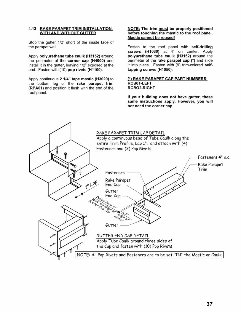
4.13 RAKE PARAPET TRIM INSTALLATION, WITH AND WITHOUT GUTTER
Stop the gutter 1/2” short of the inside face of the parapet wall.
Apply polyurethane tube caulk (H3152) around the perimeter of the corner cap (H4000) and install it in the gutter, leaving 1/2” exposed at the end. Fasten with (10) pop rivets (H1100).
Apply continuous 2 1/4” tape mastic (H3020) to the bottom leg of the rake parapet trim (RPA01) and position it flush with the end of the roof panel.
NOTE: The trim must be properly positioned before touching the mastic to the roof panel. Mastic cannot be reused!
Fasten to the roof panel with self-drillingscrews (H1030) at 4” on center. Apply polyurethane tube caulk (H3152) around the perimeter of the rake parapet cap (*) and slide it into place. Fasten with (9) trim-colored self-tapping screws (H1050).
(*) RAKE PARAPET CAP PART NUMBERS:RCB01-LEFT RCBO2-RIGHT
If your building does not have gutter, these same instructions apply. However, you will not need the corner cap.
38
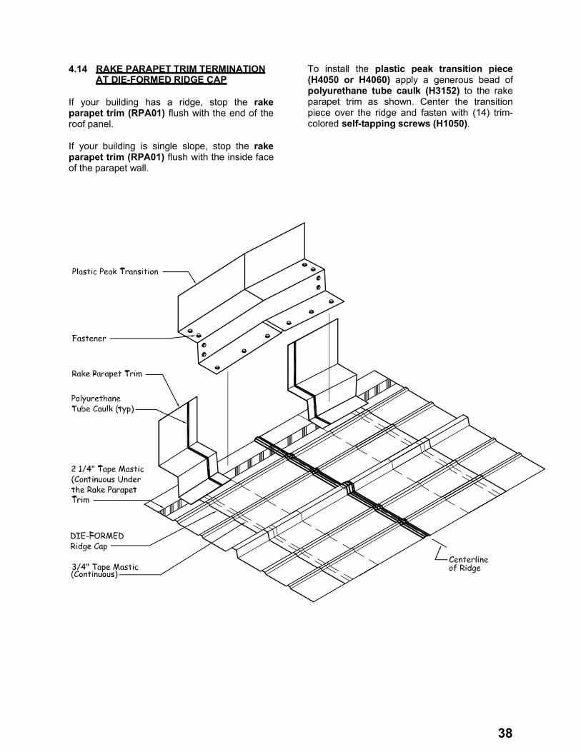
4.14 RAKE PARAPET TRIM TERMINATION AT DIE-FORMED RIDGE CAP
If your building has a ridge, stop the rake parapet trim (RPA01) flush with the end of the roof panel.
If your building is single slope, stop the rake parapet trim (RPA01) flush with the inside face of the parapet wall.
To install the plastic peak transition piece (H4050 or H4060) apply a generous bead of polyurethane tube caulk (H3152) to the rake parapet trim as shown. Center the transition piece over the ridge and fasten with (14) trim-colored self-tapping screws (H1050).
39
4.15 RAKE PARAPET TRIM TERMINATION AT PRESS-BROKE RIDGE CAP
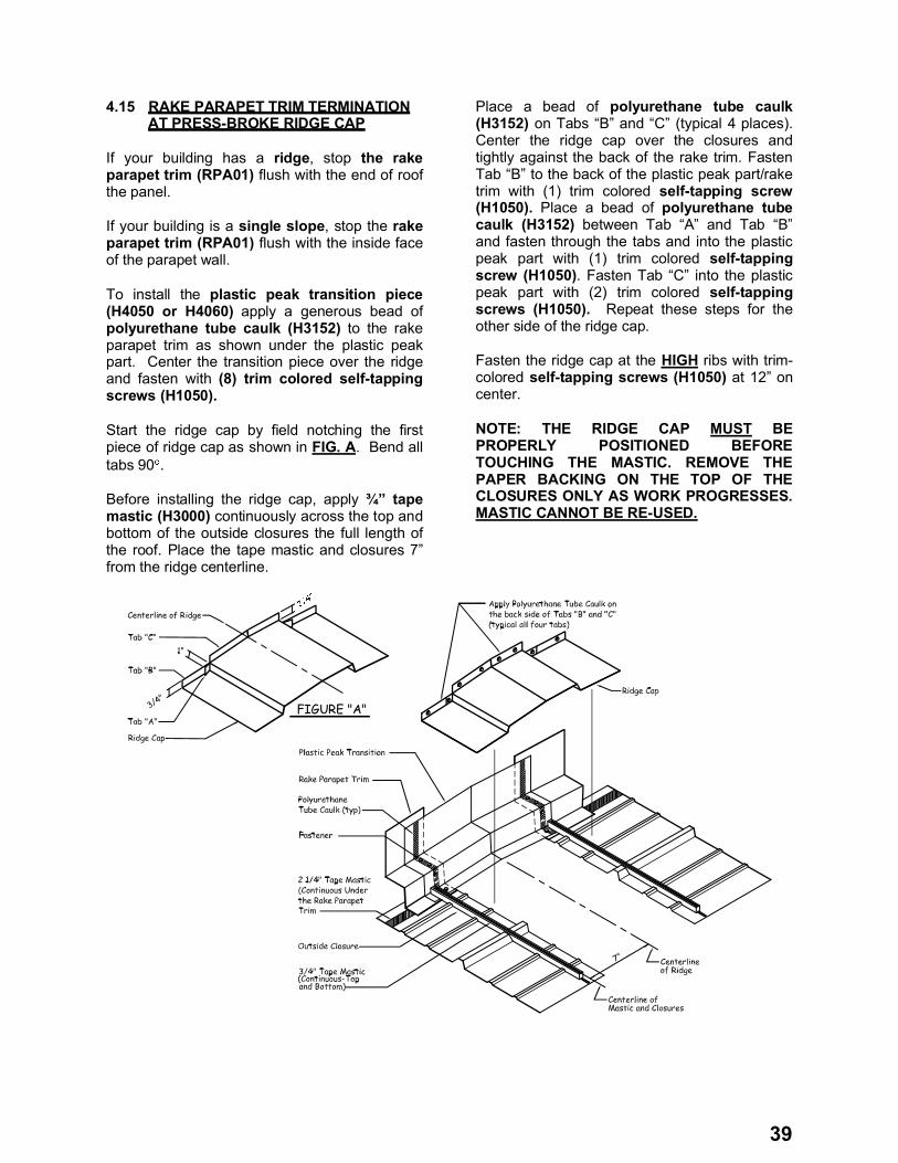
If your building has a ridge, stop the rake parapet trim (RPA01) flush with the end of roof the panel.
If your building is a single slope, stop the rakeparapet trim (RPA01) flush with the inside face of the parapet wall.
To install the plastic peak transition piece (H4050 or H4060) apply a generous bead of polyurethane tube caulk (H3152) to the rake parapet trim as shown under the plastic peak part. Center the transition piece over the ridge and fasten with (8) trim colored self-tapping screws (H1050).
Start the ridge cap by field notching the first piece of ridge cap as shown in FIG. A. Bend all tabs 90 .
Before installing the ridge cap, apply ¾” tape mastic (H3000) continuously across the top and bottom of the outside closures the full length of the roof. Place the tape mastic and closures 7” from the ridge centerline.
Place a bead of polyurethane tube caulk(H3152) on Tabs “B” and “C” (typical 4 places). Center the ridge cap over the closures and tightly against the back of the rake trim. Fasten Tab “B” to the back of the plastic peak part/rake trim with (1) trim colored self-tapping screw (H1050). Place a bead of polyurethane tube caulk (H3152) between Tab “A” and Tab “B” and fasten through the tabs and into the plastic peak part with (1) trim colored self-tapping screw (H1050). Fasten Tab “C” into the plastic peak part with (2) trim colored self-tapping screws (H1050). Repeat these steps for the other side of the ridge cap.
Fasten the ridge cap at the HIGH ribs with trim-colored self-tapping screws (H1050) at 12” on center.
NOTE: THE RIDGE CAP MUST BE PROPERLY POSITIONED BEFORE TOUCHING THE MASTIC. REMOVE THE PAPER BACKING ON THE TOP OF THE CLOSURES ONLY AS WORK PROGRESSES.MASTIC CANNOT BE RE-USED.
FIGURE "A"
Centerline of Ridge
40
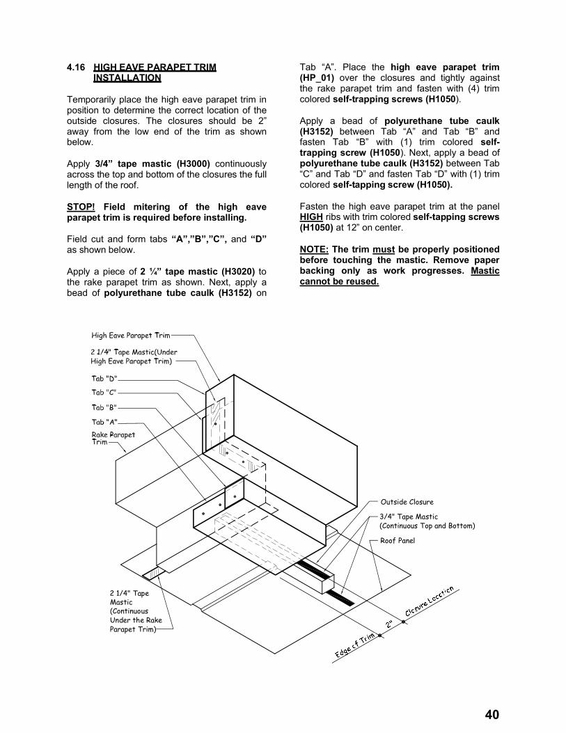
4.16 HIGH EAVE PARAPET TRIM INSTALLATION
Temporarily place the high eave parapet trim in position to determine the correct location of the outside closures. The closures should be 2” away from the low end of the trim as shown below.
Apply 3/4” tape mastic (H3000) continuously across the top and bottom of the closures the full length of the roof.
STOP! Field mitering of the high eave parapet trim is required before installing.
Field cut and form tabs “A”,”B”,”C”, and “D”as shown below.
Apply a piece of 2 ¼” tape mastic (H3020) to the rake parapet trim as shown. Next, apply a bead of polyurethane tube caulk (H3152) on
Tab “A”. Place the high eave parapet trim (HP_01) over the closures and tightly against the rake parapet trim and fasten with (4) trim colored self-trapping screws (H1050).
Apply a bead of polyurethane tube caulk (H3152) between Tab “A” and Tab “B” and fasten Tab “B” with (1) trim colored self-trapping screw (H1050). Next, apply a bead of polyurethane tube caulk (H3152) between Tab “C” and Tab “D” and fasten Tab “D” with (1) trim colored self-tapping screw (H1050).
Fasten the high eave parapet trim at the panel HIGH ribs with trim colored self-tapping screws (H1050) at 12” on center.
NOTE: The trim must be properly positioned before touching the mastic. Remove paper backing only as work progresses. Mastic cannot be reused.
3/4" Tape Mastic (Continuous Top and Bottom)
Outside Closure
Roof Panel
2 1/4" Tape Mastic (Continuous Under the Rake Parapet Trim)