dulco® turb c measuring device for turbidity, types: tuc 1 ... · dulco® turb c measuring device...
TRANSCRIPT
DULCO® turb C Measuring Device for Tur‐bidityTypes: TUC 1, TUC 2, TUC 3, TUC 4
Assembly and operating instructions
EN
Part no. 986062 BA DT 053 08/16 EN
Please carefully read these operating instructions before use. · Do not discard.The operator shall be liable for any damage caused by installation or operating errors.
The latest version of the operating instructions are available on our homepage.
General non-discriminatory approach In order to make it easier to read, thisdocument uses the male form in grammat‐ical structures but with an implied neutralsense. It is aimed equally at both men andwomen. We kindly ask female readers fortheir understanding in this simplification ofthe text.
Supplementary information
Please read the supplementary information in its entirety.
Information
This provides important information relating to the correct operation of the unit or isintended to make your work easier.
Warning information
Warning information includes detailed descriptions of the hazardous situation, seeÄ Chapter 1.1 ‘Labelling of Warning Information’ on page 6.
The following symbols are used to highlight instructions, links, lists, results and other ele‐ments in this document:
More symbols
Symbol Description
Action, step by step.
Outcome of an action.
Links to elements or sections of these instructions or other applicabledocuments.
n List without set order.
[Button] Display element (e.g. indicators).
Operating element (e.g. button, switch).
Supplemental instructions
2
Symbol Description
‘Display /GUI’ Screen elements (e.g. buttons, assignment of function keys).
CODE Presentation of software elements and/or texts.
Supplemental instructions
3

Table of contents1 Introduction............................................................................................................. 6
1.1 Labelling of Warning Information.................................................................... 61.2 Users' qualifications........................................................................................ 8
2 Safety and responsibility....................................................................................... 102.1 General safety information .......................................................................... 102.2 Correct and proper use................................................................................ 11
3 Functional description / product identification....................................................... 123.1 Scope of delivery.......................................................................................... 15
4 Assembly and Installation..................................................................................... 164.1 Wall-mounting.............................................................................................. 174.2 Installation (hydraulic).................................................................................. 204.3 Installation (electrical)................................................................................... 22
5 Operating diagram................................................................................................ 275.1 Overview of device /Control elements.......................................................... 275.2 Overview of operating structure................................................................... 28
6 Commissioning..................................................................................................... 316.1 Inserting the drying agent............................................................................. 326.2 Routine measurement.................................................................................. 356.3 Access code................................................................................................. 366.4 Device configuration..................................................................................... 376.4.1 Selecting the output................................................................................... 376.4.2 Configuration of fault current (ERLV)........................................................ 396.4.3 Configure alarm ........................................................................................ 406.4.4 OFFSET configuration............................................................................... 426.4.5 Extended settings...................................................................................... 44
7 Operation.............................................................................................................. 557.1 Calibrating DULCO® turb C.......................................................................... 557.1.1 Standard solutions for calibration.............................................................. 557.1.2 Perform calibration.................................................................................... 61
8 Maintenance, troubleshooting and repair............................................................. 688.1 Information about troubleshooting................................................................ 688.1.1 System error messages............................................................................ 69
Table of contents
4
8.1.2 Faults in the process................................................................................. 69
9 Spare parts and accessories................................................................................ 71
10 Disposal of Used Parts......................................................................................... 72
11 Declaration of Conformity..................................................................................... 73
12 Index..................................................................................................................... 74
Table of contents
5
1 IntroductionData and functions
These operating instructions describe thetechnical data and functions of theDULCO® turb C Measuring Device forTurbidity.
1.1 Labelling of Warning Infor‐mation
Introduction
These operating instructions provide infor‐mation on the technical data and functionsof the product. These operating instruc‐tions provide detailed warning informationand are provided as clear step-by-stepinstructions.
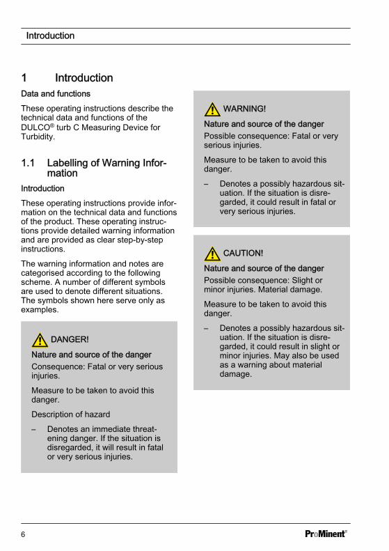
The warning information and notes arecategorised according to the followingscheme. A number of different symbolsare used to denote different situations.The symbols shown here serve only asexamples.
DANGER!
Nature and source of the dangerConsequence: Fatal or very seriousinjuries.
Measure to be taken to avoid thisdanger.
Description of hazard
– Denotes an immediate threat‐ening danger. If the situation isdisregarded, it will result in fatalor very serious injuries.
WARNING!
Nature and source of the dangerPossible consequence: Fatal or veryserious injuries.
Measure to be taken to avoid thisdanger.
– Denotes a possibly hazardous sit‐uation. If the situation is disre‐garded, it could result in fatal orvery serious injuries.
CAUTION!
Nature and source of the dangerPossible consequence: Slight orminor injuries. Material damage.
Measure to be taken to avoid thisdanger.
– Denotes a possibly hazardous sit‐uation. If the situation is disre‐garded, it could result in slight orminor injuries. May also be usedas a warning about materialdamage.
Introduction
6

NOTICE!
Nature and source of the dangerDamage to the product or its sur‐roundings.
Measure to be taken to avoid thisdanger.
– Denotes a possibly damaging sit‐uation. If the situation is disre‐garded, the product or an objectin its vicinity could be damaged.
Type of informationHints on use and additional informa‐tion.Source of the information. Additionalmeasures.– Denotes hints on use and other
useful information. It does notindicate a hazardous or dam‐aging situation.
Introduction
7
1.2 Users' qualifications
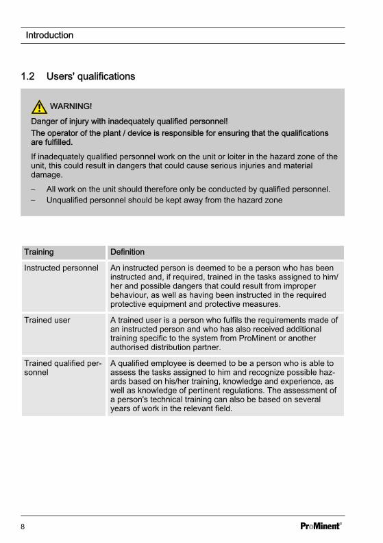
WARNING!
Danger of injury with inadequately qualified personnel!The operator of the plant / device is responsible for ensuring that the qualificationsare fulfilled.
If inadequately qualified personnel work on the unit or loiter in the hazard zone of theunit, this could result in dangers that could cause serious injuries and materialdamage.
– All work on the unit should therefore only be conducted by qualified personnel.– Unqualified personnel should be kept away from the hazard zone
Training Definition
Instructed personnel An instructed person is deemed to be a person who has beeninstructed and, if required, trained in the tasks assigned to him/her and possible dangers that could result from improperbehaviour, as well as having been instructed in the requiredprotective equipment and protective measures.
Trained user A trained user is a person who fulfils the requirements made ofan instructed person and who has also received additionaltraining specific to the system from ProMinent or anotherauthorised distribution partner.
Trained qualified per‐sonnel
A qualified employee is deemed to be a person who is able toassess the tasks assigned to him and recognize possible haz‐ards based on his/her training, knowledge and experience, aswell as knowledge of pertinent regulations. The assessment ofa person's technical training can also be based on severalyears of work in the relevant field.
Introduction
8
Training Definition
Electrician Electricians are deemed to be people, who are able to com‐plete work on electrical systems and recognize and avoid pos‐sible hazards independently based on his/her technical trainingand experience, as well as knowledge of pertinent standardsand regulations.
Electricians should be specifically trained for the working envi‐ronment in which the are employed and know the relevantstandards and regulations.
Electricians must comply with the provisions of the applicablestatutory directives on accident prevention.
Customer Servicedepartment
Customer Service department refers to service technicians,who have received proven training and have been authorisedby ProMinent to work on the system.
Note for the system operatorThe pertinent accident prevention regulations, as well as all other generally acknowl‐edged safety regulations, must be adhered to!
Introduction
9

2 Safety and responsibility2.1 General safety information
WARNING!
Live parts!Possible consequence: Fatal or veryserious injuries
– Measure: Disconnect the mainspower supply prior to opening thehousing
– Disconnect damaged, defectiveor manipulated devices from thepower supply
WARNING!
Unauthorised access!Possible consequence: Fatal or veryserious injuries.
– Measure: Ensure that there canbe no unauthorised access to theunit
WARNING!
Operating errors!Possible consequence: Fatal or veryserious injuries.
– The unit should only be operatedby adequately qualified and tech‐nically expert personnel
– Please also observe the oper‐ating instructions for controllersand fittings and any other compo‐nent groups, such as sensors,sample water pumps ...
– The operator is responsible forensuring that personnel are quali‐fied
CAUTION!
Electronic malfunctionsPossible consequence: Materialdamage right through to destruction ofthe unit
– The mains connection cable anddata cable should not be laidtogether with cables that areprone to interference
– Measure: Take appropriate inter‐ference suppression measures
Safety and responsibility
10
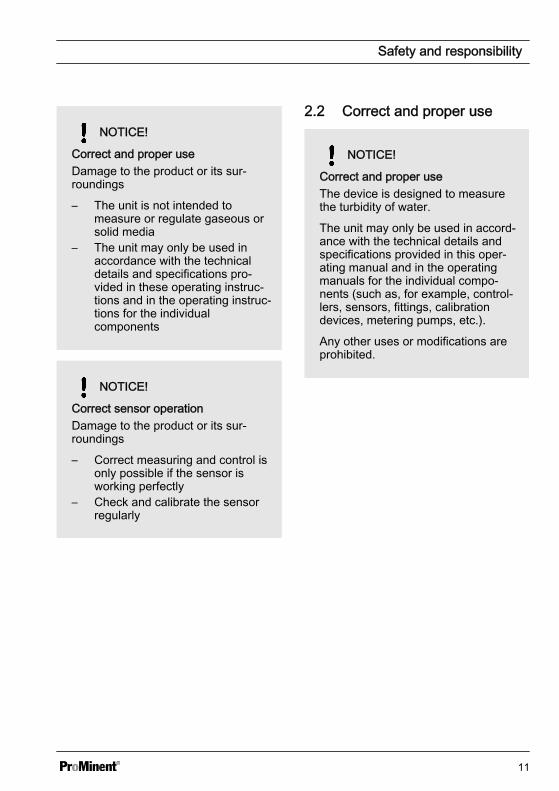
NOTICE!
Correct and proper useDamage to the product or its sur‐roundings
– The unit is not intended tomeasure or regulate gaseous orsolid media
– The unit may only be used inaccordance with the technicaldetails and specifications pro‐vided in these operating instruc‐tions and in the operating instruc‐tions for the individualcomponents
NOTICE!
Correct sensor operationDamage to the product or its sur‐roundings
– Correct measuring and control isonly possible if the sensor isworking perfectly
– Check and calibrate the sensorregularly
2.2 Correct and proper use
NOTICE!
Correct and proper useThe device is designed to measurethe turbidity of water.
The unit may only be used in accord‐ance with the technical details andspecifications provided in this oper‐ating manual and in the operatingmanuals for the individual compo‐nents (such as, for example, control‐lers, sensors, fittings, calibrationdevices, metering pumps, etc.).
Any other uses or modifications areprohibited.
Safety and responsibility
11

3 Functional description / product identificationBrief description of the function
The DULCO® turb C has been developed for the online measurement of turbid matter inuntreated water, process water and treated process water in drinking water abstraction.
The DULCO® turb C product line consists of four types of device:
Types TUC 1 and TUC 3 work with infrared light and fulfil the requirements of the interna‐tional standards ISO 7027 and DIN EN 27027.
Types TUC 2 and TUC 4 work with achromatic light and fulfil USA standard US EPA180.1.
All device types can be equipped with ultrasonic cleaning (TUC 3 / TUC 4) or withoutultrasonic cleaning (TUC 1 / TUC 2). The sample cell ultrasonic cleaning system extendsthe calibration and maintenance intervals in media where coating formation is common.
DULCO® turb C Partnumber
ISO 7027
DIN EN27027
US EPA180.1
Ultrasonic cleaning
TUC 1 1037696 Infraredlight
No
TUC 2 1037695 Achromaticlight
No
TUC 3 1037698 Infraredlight
Yes
TUC 4 1037697 Achromaticlight
Yes
An inlet side pressure regulating valve is standard. The DULCO turb C pressure regu‐lating valve reduces the pressure from up to 13.8 bar (200 PSI) to 1.0 bar (15 PSI).
Functional description / product identification
12
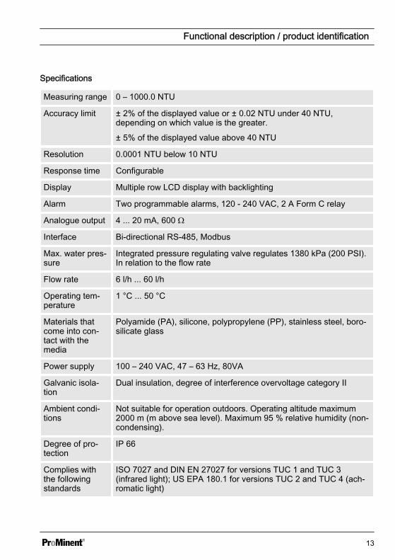
Specifications
Measuring range 0 – 1000.0 NTU
Accuracy limit ± 2% of the displayed value or ± 0.02 NTU under 40 NTU,depending on which value is the greater.
± 5% of the displayed value above 40 NTU
Resolution 0.0001 NTU below 10 NTU
Response time Configurable
Display Multiple row LCD display with backlighting
Alarm Two programmable alarms, 120 - 240 VAC, 2 A Form C relay
Analogue output 4 ... 20 mA, 600 Ω
Interface Bi-directional RS-485, Modbus
Max. water pres‐sure
Integrated pressure regulating valve regulates 1380 kPa (200 PSI).In relation to the flow rate
Flow rate 6 l/h ... 60 l/h
Operating tem‐perature
1 °C ... 50 °C
Materials thatcome into con‐tact with themedia
Polyamide (PA), silicone, polypropylene (PP), stainless steel, boro‐silicate glass
Power supply 100 – 240 VAC, 47 – 63 Hz, 80VA
Galvanic isola‐tion
Dual insulation, degree of interference overvoltage category II
Ambient condi‐tions
Not suitable for operation outdoors. Operating altitude maximum2000 m (m above sea level). Maximum 95 % relative humidity (non-condensing).
Degree of pro‐tection
IP 66
Complies withthe followingstandards
ISO 7027 and DIN EN 27027 for versions TUC 1 and TUC 3(infrared light); US EPA 180.1 for versions TUC 2 and TUC 4 (ach‐romatic light)
Functional description / product identification
13
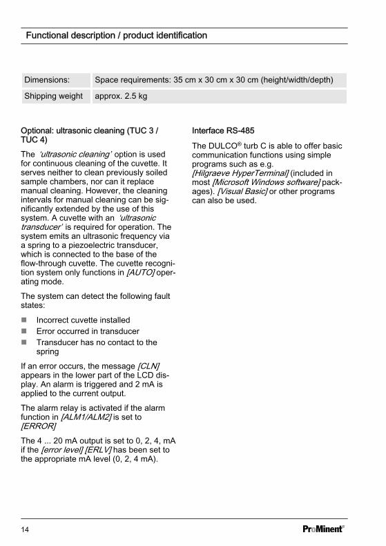
Dimensions: Space requirements: 35 cm x 30 cm x 30 cm (height/width/depth)
Shipping weight approx. 2.5 kg
Optional: ultrasonic cleaning (TUC 3 /TUC 4)
The ‘ultrasonic cleaning’ option is usedfor continuous cleaning of the cuvette. Itserves neither to clean previously soiledsample chambers, nor can it replacemanual cleaning. However, the cleaningintervals for manual cleaning can be sig‐nificantly extended by the use of thissystem. A cuvette with an ‘ultrasonictransducer’ is required for operation. Thesystem emits an ultrasonic frequency viaa spring to a piezoelectric transducer,which is connected to the base of theflow-through cuvette. The cuvette recogni‐tion system only functions in [AUTO] oper‐ating mode.
The system can detect the following faultstates:
n Incorrect cuvette installedn Error occurred in transducern Transducer has no contact to the
spring
If an error occurs, the message [CLN]appears in the lower part of the LCD dis‐play. An alarm is triggered and 2 mA isapplied to the current output.
The alarm relay is activated if the alarmfunction in [ALM1/ALM2] is set to[ERROR]The 4 ... 20 mA output is set to 0, 2, 4, mAif the [error level] [ERLV] has been set tothe appropriate mA level (0, 2, 4 mA).
Interface RS-485
The DULCO® turb C is able to offer basiccommunication functions using simpleprograms such as e.g.[Hilgraeve HyperTerminal] (included inmost [Microsoft Windows software] pack‐ages). [Visual Basic] or other programscan also be used.
Functional description / product identification
14
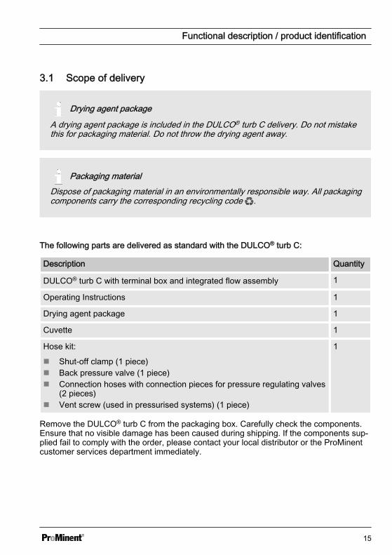
3.1 Scope of delivery
Drying agent package
A drying agent package is included in the DULCO® turb C delivery. Do not mistakethis for packaging material. Do not throw the drying agent away.
Packaging materialDispose of packaging material in an environmentally responsible way. All packagingcomponents carry the corresponding recycling code .
The following parts are delivered as standard with the DULCO® turb C:
Description Quantity
DULCO® turb C with terminal box and integrated flow assembly 1
Operating Instructions 1
Drying agent package 1
Cuvette 1
Hose kit:
n Shut-off clamp (1 piece)n Back pressure valve (1 piece)n Connection hoses with connection pieces for pressure regulating valves
(2 pieces)n Vent screw (used in pressurised systems) (1 piece)
1
Remove the DULCO® turb C from the packaging box. Carefully check the components.Ensure that no visible damage has been caused during shipping. If the components sup‐plied fail to comply with the order, please contact your local distributor or the ProMinentcustomer services department immediately.
Functional description / product identification
15
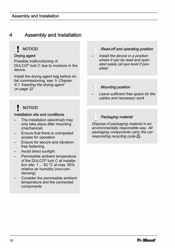
4 Assembly and Installation
NOTICE!
Drying agentPossible malfunctioning ofDULCO® turb C due to moisture in thedevice.
Install the drying agent bag before ini‐tial commissioning, see Ä Chapter6.1 ‘Inserting the drying agent’on page 32
NOTICE!
Installation site and conditions– The installation (electrical) may
only take place after mounting(mechanical)
– Ensure that there is unimpededaccess for operation
– Ensure for secure and vibration-free fastening.
– Avoid direct sunlight– Permissible ambient temperature
of the DULCO® turb C at installa‐tion site: 1 ... 50 °C at max. 95%relative air humidity (non-con‐densing)
– Consider the permissible ambienttemperature and the connectedcomponents
Read-off and operating position– Install the device in a position
where it can be read and oper‐ated easily (at eye level if pos‐sible)
Mounting position– Leave sufficient free space for the
cables and necessary work
Packaging materialDispose of packaging material in anenvironmentally responsible way. Allpackaging components carry the cor‐responding recycling code .
Assembly and Installation
16
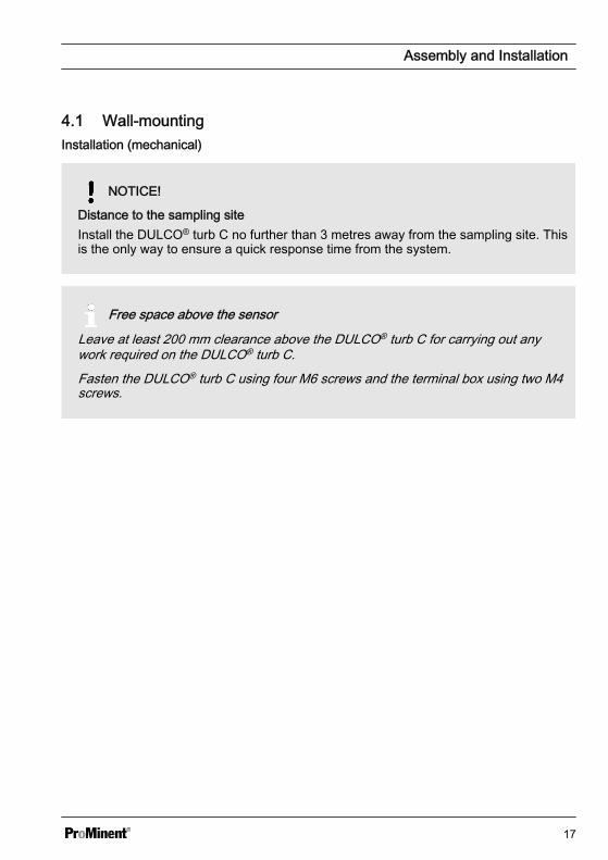
4.1 Wall-mountingInstallation (mechanical)
NOTICE!
Distance to the sampling siteInstall the DULCO® turb C no further than 3 metres away from the sampling site. Thisis the only way to ensure a quick response time from the system.
Free space above the sensor
Leave at least 200 mm clearance above the DULCO® turb C for carrying out anywork required on the DULCO® turb C.Fasten the DULCO® turb C using four M6 screws and the terminal box using two M4screws.
Assembly and Installation
17
A0515
A
B
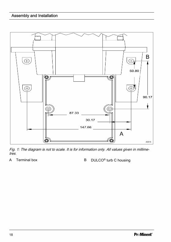
Fig. 1: The diagram is not to scale. It is for information only. All values given in millime‐tres.A Terminal box B DULCO® turb C housing
Assembly and Installation
18
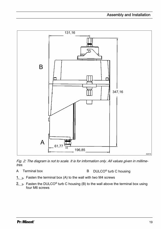
Fig. 2: The diagram is not to scale. It is for information only. All values given in millime‐tres.A Terminal box B DULCO® turb C housing
1. Fasten the terminal box (A) to the wall with two M4 screws
2. Fasten the DULCO® turb C housing (B) to the wall above the terminal box usingfour M6 screws
Assembly and Installation
19
4.2 Installation (hydraulic)
CAUTION!
Free flow at outletDirect any sample water that hasflowed through the DULCO® turb Cinto a free outlet. The sampled watermay not be fed back into the process.
CAUTION!
Algae growth under the influence oflightPossible algae growth if unsuitablehoses are used.
Do not use transparent hoses if theinstallation is subjected to powerfulsources of light. This prevents the for‐mation of algae in the installation.
Leakage on the vent screwSlight leakage may occur at the borehole for the vent screw during theinstallation process. This will cease assoon as normal flow is established.In the event that the installation con‐tinues to leak permanently at thispoint due to the high pressure in thisarea, we recommend sealing off thebore hole with the sealing plug sup‐plied. In order to ensure freedrainage, a bleed option must beinstalled at another area of the outletin order to avoid overpressure orunderpressure in the system.
Permissible operating parame‐ters– Maximum liquid temperature 50
°C– Maximum pressure 13.8 bar– Flow rate 6 ... 60 l/h
Assembly and Installation
20
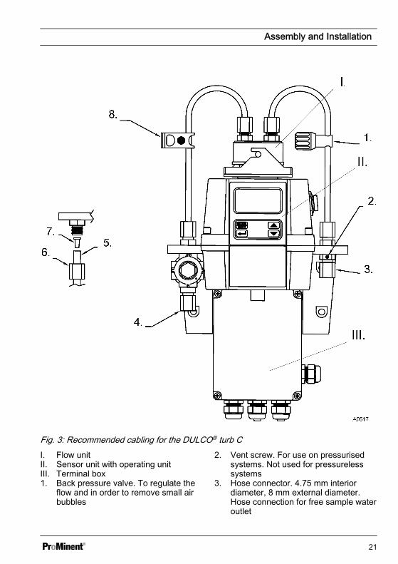
Fig. 3: Recommended cabling for the DULCO® turb CI. Flow unitII. Sensor unit with operating unitIII. Terminal box1. Back pressure valve. To regulate the
flow and in order to remove small airbubbles
2. Vent screw. For use on pressurisedsystems. Not used for pressurelesssystems
3. Hose connector. 4.75 mm interiordiameter, 8 mm external diameter.Hose connection for free sample wateroutlet
Assembly and Installation
21
4. Hose connector. 4.75 mm interiordiameter, 8 mm external diameter.Hose connection to the sampling site
5. Detail: Hose
6. Detail: Union nut hose connection7. Detail: Replacement hose connection8. Shut-off clamp. To shut-off the inlet in
an emergency or for necessary work4.3 Installation (electrical)
WARNING!
Live parts!Possible consequence: Fatal or veryserious injuries
– Measure: Disconnect the powersupply before opening thehousing
– Disconnect damaged, defectiveor manipulated devices from thepower supply
– The provision of a suitable iso‐lating device (emergency-offswitch, etc.) is the responsibilityof the plant operator
NOTICE!
Do not route any RS-485 cables inthe same cable duct as the powersupply cable. This may result in majoranomalies.
The signal leads of theDULCO® turb C may not be routedalongside faulty cabling. Faults couldlead to malfunctions in theDULCO® turb C.
Assembly and Installation
22

RS-485The RS-485 digital interface (2 leads / half duplex) is characterised by a very hightolerance to electromagnetic interference due to the symmetrical signal transmission.This means that cable lengths of up to 900m can be used. The final device on a busmust be equipped with a 120 ohm resistor, in order to avoid signal overlapping.In order to avoid damage, only separate and connect the RS-485 cable if theDULCO® turb C is switched off.
Assembly and Installation
23
A0518
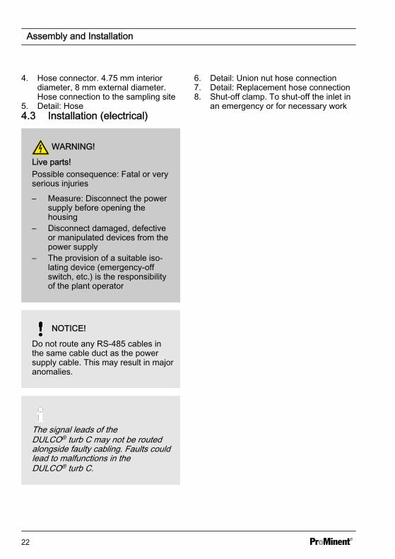
Fig. 4: Cable assignment for DULCO® turb C1. Sensor cable2. Liquid-tight threaded connection
3. Terminal box
Assembly and Installation
24
A0646
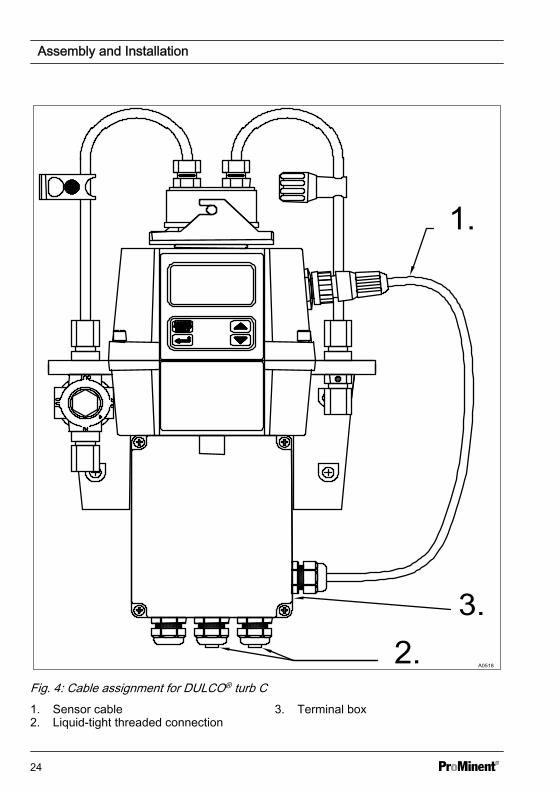
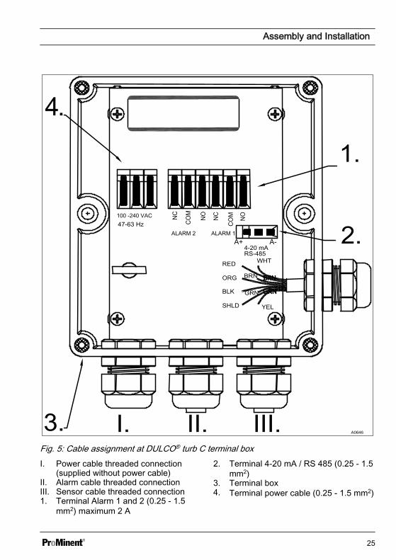
Fig. 5: Cable assignment at DULCO® turb C terminal boxI. Power cable threaded connection
(supplied without power cable)II. Alarm cable threaded connectionIII. Sensor cable threaded connection1. Terminal Alarm 1 and 2 (0.25 - 1.5
mm2) maximum 2 A
2. Terminal 4-20 mA / RS 485 (0.25 - 1.5mm2)
3. Terminal box4. Terminal power cable (0.25 - 1.5 mm2)
Assembly and Installation
25
All terminals in the terminal box are labelled and are self-explanatory.All cable bushings are equipped with blanks on shipping. These must be removed asrequired.Strip the Insulation on all cables to a length of 6 mm.Equip all cables with strain relief.Supply voltage: 100 - 240 VAC at 47 - 63 Hz
1. Release the four housing screws from the corners of the terminal box.
2. Lift off the terminal box cover.
3. Remove the blanks from the required bore holes
4. Guide the cables into the threaded connectors
5. Connect the cables with the designated terminals.
6. Tighten the clamping nuts of the threaded connections so that they are properlysealed
7. Place the terminal box cover back onto the terminal box
8. Manually tighten the housing screws
9. Once again check the seating of the seals and threaded connections. Protectionclass IP 66 is only achieved if the control panel mounting is correct
Assembly and Installation
26
5 Operating diagram5.1 Overview of device /Control elementsn Users' qualification: Instructed person, see Ä Chapter 1.2 ‘Users' qualifications’
on page 8
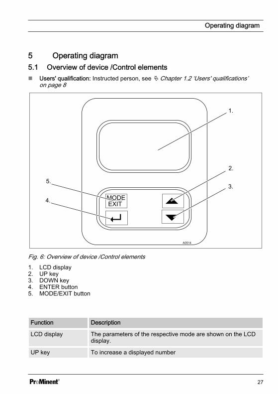
Fig. 6: Overview of device /Control elements1. LCD display2. UP key3. DOWN key4. ENTER button5. MODE/EXIT button
Function Description
LCD display The parameters of the respective mode are shown on the LCDdisplay.
UP key To increase a displayed number
Operating diagram
27
Function Description
DOWN key To decrease a displayed number
ENTER button To apply, confirm or save a displayed value or status or
MODE/EXIT button In order to call-up and select the three optional modes [CAL],[CONFIG] and [AUTO] (measurement)
5.2 Overview of operating struc‐ture
The sensor is equipped with three modes,which can be selected by means of theMODE/EXIT button:
n [AUTO mode]: Standard mode, dis‐play of the current measured values
n [CAL]: Calibration mode for executingthe calibration process
n [CONFIG]: Configuration mode forconfiguring customer-specific set‐tings. Automatic switchover into themode [AUTO mode] if no entry under‐taken within 15 minutes
Operating diagram
28
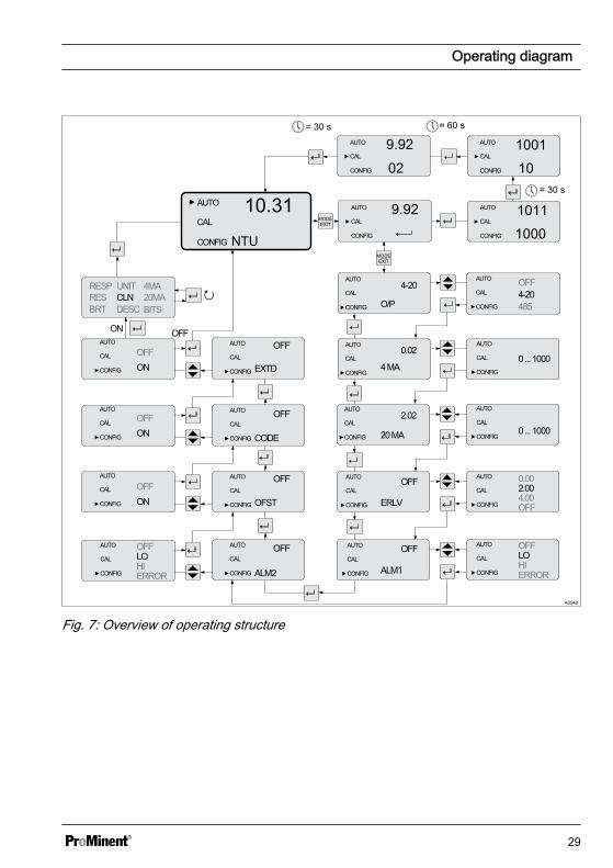
Fig. 7: Overview of operating structure
Operating diagram
29
Configuration menu
The configuration menu is subdivided intoseveral submenus, in order to facilitateconfiguration.
The following submenus are available:
n Select the output [O/P]n Configuration of 4 ... 20 mA interface
[ERLV]n Configuration of the alarm
[ALM1 / ALM2]n Configuration of the offset [OFST]n Configuration of access protection
[CODE]n Extended settings [EXTD]The procedure for configuring the menusettings is described here Ä Chapter 6.4‘Device configuration’ on page 37 .
The extended settings are groupedtogether in order to prevent accidentalalteration.
n Speed of response [RESP]n Screen resolution [RES]n LCD illumination brightness [BRT]n Displayed units [UNIT]n Ultrasonic cleaning [CLN]n RS-485 parameters [BITS]n Drying agent alarm [DESC]The procedure for configuring theextended settings is described hereÄ Chapter 6.4.5 ‘Extended settings’on page 44 .
Operating diagram
30
6 CommissioningUnit NTU (optionally FNU)
The NTU (Nephelometric Turbidity Unit) is a unit used for measuring turbidity in liquids.Alternatively, the measured value may be displayed in FNU (Formazine NephelometricUnit), see Ä ‘Units’ on page 48. The calculation is undertaken 1:1.
Measured values above 1000 NTU fall outside the measuring range of this DULCO® turbC. Measured values above 1100 NTU cause the display to flash and issue a messageindicating that the measured value is too high.
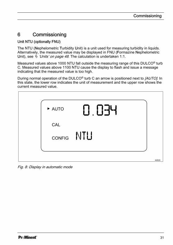
During normal operation of the DULCO® turb C an arrow is positioned next to [AUTO]. Inthis state, the lower row indicates the unit of measurement and the upper row shows thecurrent measured value.
Fig. 8: Display in automatic mode
Commissioning
31
6.1 Inserting the drying agent
Remove transport mountingThe transport mounting must be removed before initial insertion of the drying agentbag. This pipe can be subsequently disposed of.
The DULCO® turb C is equipped with a dehumidifying device. A drying agent bag in theDULCO® turb C dries the air. The thermal discharge from the sensor is used to heat theair. A fan mounted in the inner part of the DULCO® turb C circulates the warm air aroundthe optical sleeve and cuvette. DULCO® turb C continuously monitors the state of thedrying agent bag. As soon as the drying agent needs to be exchanged, this is indicated inthe lower row of the LCD display; Warning [DESC] (for [Desiccant] = drying agent).Replacement drying agent bags can be obtained from Prominent or from your local rep‐resentative.
Saturated drying agent can cause an alarm to be triggered, in order to indicate therequirement for exchange. Refer to Ä ‘Drying agent alarm’ on page 51
NOTICE!
Seal sensor housingPossibility of premature drying agent saturation.
A damaged seal can lead to premature saturation of the drying agent.
Check the seal every time the drying agent is exchanged. Correct the seal seating orexchange the seal if necessary.
1. Release the screws from the corners of the housing and remove the upper part ofthe DULCO® turb C
Commissioning
32
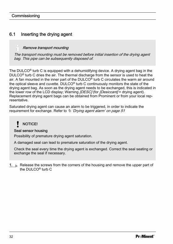
Fig. 9: Inserting the drying agent2. Insert the drying agent immediately after opening the packaging, in order to avoid
premature saturation.
Remove the new drying agent bag (2) from the packaging and place it togetherwith the humidity indicator card (3) in the lower part of the DULCO® turb C (1). Indoing so, place the humidity indicator card (3) on the new drying agent bag (2).
3. Place the upper part back on the lower part and tighten the four screws hand-tight.
Commissioning
33
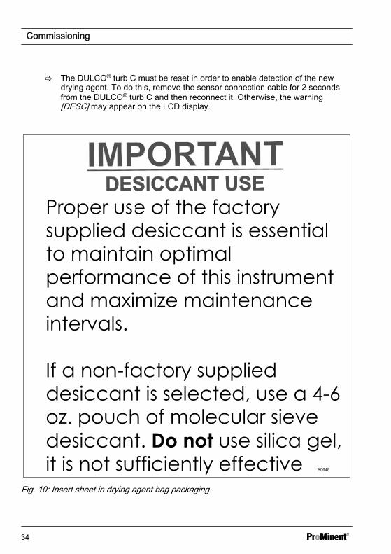
ð The DULCO® turb C must be reset in order to enable detection of the newdrying agent. To do this, remove the sensor connection cable for 2 secondsfrom the DULCO® turb C and then reconnect it. Otherwise, the warning[DESC] may appear on the LCD display.
A0648
Fig. 10: Insert sheet in drying agent bag packaging
Commissioning
34
Always use the original packaging. If you do not have any of the original drying agent,use 113 ... 170 grammes zeolite-based drying agent (molecular sieve) of similar quality(3 Å pore width). Silica gel and other chemical drying agents may not be used.
6.2 Routine measurementRoutine measurement: The turbidity canbe correctly measured approx. 45 - 60minutes after beginning measurement /commissioning (warm-up phase).
When a continuous process water flow ispassing through the DULCO® turb C, theDULCO® turb C indicates the measuredturbidity level of the sample on the LCDdisplay. In addition, a 4-20 mA signal or adigital signal is given, depending on theselected option.
Commissioning
35
6.3 Access code
The access code cannot be changed.
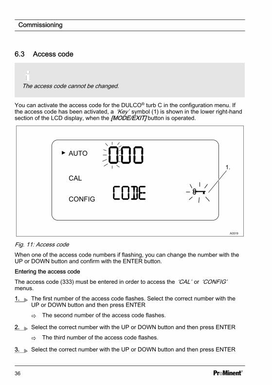
You can activate the access code for the DULCO® turb C in the configuration menu. Ifthe access code has been activated, a ‘Key’ symbol (1) is shown in the lower right-handsection of the LCD display, when the [MODE/EXIT] button is operated.
A0519
Fig. 11: Access codeWhen one of the access code numbers if flashing, you can change the number with theUP or DOWN button and confirm with the ENTER button.
Entering the access code
The access code (333) must be entered in order to access the ‘CAL’ or ‘CONFIG’menus.
1. The first number of the access code flashes. Select the correct number with theUP or DOWN button and then press ENTER
ð The second number of the access code flashes.
2. Select the correct number with the UP or DOWN button and then press ENTER
ð The third number of the access code flashes.
3. Select the correct number with the UP or DOWN button and then press ENTER
Commissioning
36
ð If you have selected the valid access code, you will now have access to theDULCO® turb C's calibration mode. If the access code is incorrect, theDULCO® turb C returns to AUTO mode.
6.4 Device configuration6.4.1 Selecting the output
A0530
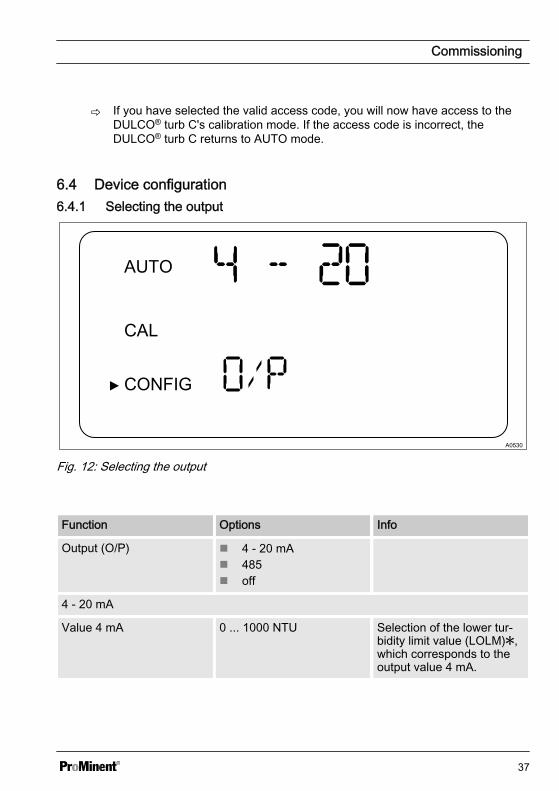
Fig. 12: Selecting the output
Function Options Info
Output (O/P) n 4 - 20 mAn 485n off
4 - 20 mA
Value 4 mA 0 ... 1000 NTU Selection of the lower tur‐bidity limit value (LOLM),which corresponds to theoutput value 4 mA.
Commissioning
37
Function Options Info
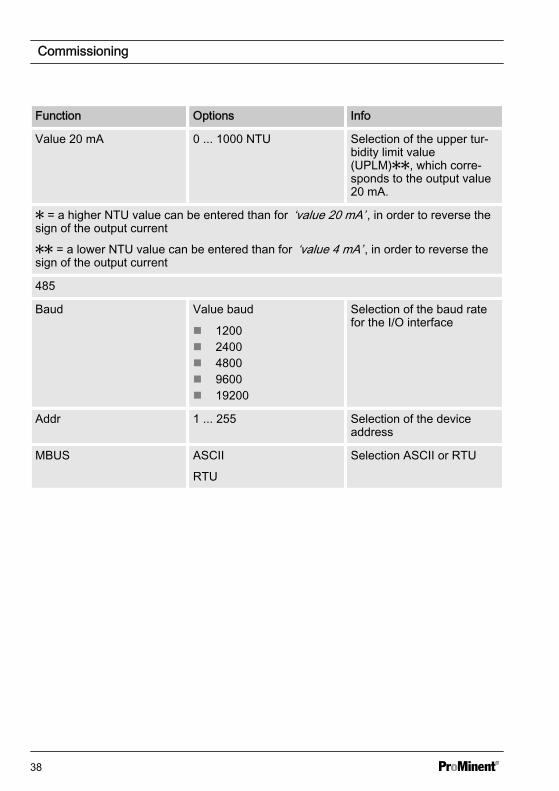
Value 20 mA 0 ... 1000 NTU Selection of the upper tur‐bidity limit value(UPLM), which corre‐sponds to the output value20 mA.
= a higher NTU value can be entered than for ‘value 20 mA’ , in order to reverse thesign of the output current
= a lower NTU value can be entered than for ‘value 4 mA’ , in order to reverse thesign of the output current
485
Baud Value baud
n 1200n 2400n 4800n 9600n 19200
Selection of the baud ratefor the I/O interface
Addr 1 ... 255 Selection of the deviceaddress
MBUS ASCII
RTU
Selection ASCII or RTU
Commissioning
38
6.4.2 Configuration of fault current (ERLV)
A0625
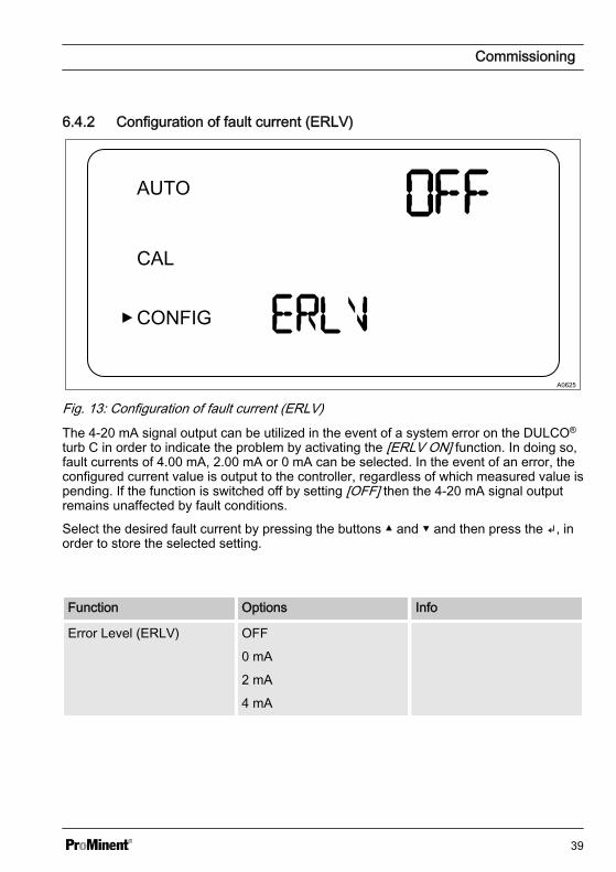
Fig. 13: Configuration of fault current (ERLV)The 4-20 mA signal output can be utilized in the event of a system error on the DULCO®
turb C in order to indicate the problem by activating the [ERLV ON] function. In doing so,fault currents of 4.00 mA, 2.00 mA or 0 mA can be selected. In the event of an error, theconfigured current value is output to the controller, regardless of which measured value ispending. If the function is switched off by setting [OFF] then the 4-20 mA signal outputremains unaffected by fault conditions.
Select the desired fault current by pressing the buttons and and then press the , inorder to store the selected setting.
Function Options Info
Error Level (ERLV) OFF
0 mA
2 mA
4 mA
Commissioning
39
6.4.3 Configure alarmThe DULCO® turb C is equipped with twoindependently programmable alarmrelays. Three items of information have tobe entered in order to fully configure thealarms:
n Alarm function: HI, LO, OFF orERROR
n Alarm limit value (limit value at whichthe alarm becomes active)
n Alarm delay time (how long the limitvalue must be exceeded before thealarm is activated and the period oftime before the alarm is reset)
Alarm function
Alarm triggering in the event ofan internal system errorThe relay produces an alarm in theevent of an internal system error,regardless of the configured turbidityvalues.
You can either deactivate the alarm (OFF)or program it so that it works in accord‐ance with one of the following modes:
n Alarm HI: The relay triggers the alarmin the event that the turbidity valueexceeds the programmed alarm valuefor at least the specified period of time
n Alarm LO: The relay triggers thealarm in the event that the turbidityvalue drops below the programmedalarm value for at least the specifiedperiod of time
n Alarm ERROR: The relay triggers thealarm when an internal system erroroccurs
Limit value alarm
The turbidity threshold at which the alarmis triggered is referred to as the ‘Limitvalue alarm’ . You can configure the limitvalue across the entire display range ofthe device in steps of 0.01 NTU.
Delay period alarm
The alarm delay times prevent the alarmfrom being triggered in the event that theturbidity briefly exceeds or drops belowthe threshold value. The delay functionworks as follows:
n Delay time ‘Alarm on’ : The turbiditymust exceed the ‘Limit value alarm’for at least the number of seconds sethere before the alarm is activated. Ifthe time of the ‘Delay alarm on’ is setto 5 seconds and the turbidityexceeds the ‘Limit value alarm’ foronly 4 seconds, the alarm will not beactivated. However, if the turbidityexceeds the ‘Limit value’ for 5 sec‐onds or longer, the sensor triggers analarm.
n Delay time ‘Alarm off’ : The turbiditymust remain under the ‘Limit valuealarm’ for at least the number of sec‐onds set here before the alarm isdeactivated. If the time of the ‘Delayalarm off’ has been set to 5 secondsand the turbidity remains under the‘Limit value alarm’ for only 4 sec‐onds, the alarm will not be deacti‐vated. As soon as the turbidityremains below the ‘Limit value alarm’for at least 5 seconds, the sensordeactivates the alarm.
Commissioning
40

Menu Alarm
A0531
Fig. 14: Menu Alarm
Operation Options Info
Alarm 1 (ALM1)
or
Alarm 2 (ALM2)
n HIn LOn OFFn ERROR
Select the alarm function
Limit value (S/P) 0 ... 1000 NTU Set the ‘Limit value alarm’
Delay time alarm on(DLY)
1 ... 30 s Set the number of secondsfor the ‘Delay alarm on’function.
Delay time alarm off(DLY)
1 ... 30 s Set the number of secondsfor the ‘Delay alarm off’function.
Commissioning
41

6.4.4 OFFSET configuration
The OFFSET symbol is shows as soon as an offset is being used. The maximumoffset amounts to 1.00 NTU. If the device deviation is greater than 1 NTU, then it isrecommended to carry out a complete calibration.
A0624
Fig. 15: OFFSET configuration
Commissioning
42
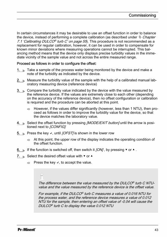
In certain circumstances it may be desirable to use an offset function in order to balancethe device, instead of performing a complete calibration (as described under Ä Chapter7.1 ‘Calibrating DULCO® turb C’ on page 55). This procedure is not recommended as areplacement for regular calibration, however, it can be used in order to compensate forknown minor deviations where measuring operations cannot be interrupted. This bal‐ancing method means that the device only displays precise turbidity values in the imme‐diate vicinity of the sample value and not across the entire measured range.
Proceed as follows in order to configure the offset:
1. Take a sample of the process water being monitored by the device and make anote of the turbidity as indicated by the device.
2. Measure the turbidity value of the sample with the help of a calibrated manual lab‐oratory measuring device (reference device)
3. Compare the turbidity value indicated by the device with the value measured bythe reference device. If the values are extremely close to each other (dependingon the accuracy of the reference device), then no offset configuration or calibrationis required and the procedure can be aborted at this point.
ð However, if the values differ significantly (however, less than 1 NTU), then pro‐ceed as follows in order to improve the turbidity value for the device, so thatthe device matches the laboratory value.
4. Select the offset function by pressing [MODE/EXIT button] until the arrow is posi‐tioned next to [CONFIG]
5. Press the key , until [OFST] is shown in the lower row
ð At this point, the upper row of the display indicates the operating condition ofthe offset function.
6. If the function is switched off, then switch it [ON] , by pressing or .
7. Select the desired offset value with or
ð Press the key , to accept the value.
The difference between the value measured by the DULCO® turb C NTU-value and the value measured by the reference device is the offset value.For example, if the DULCO® turb C measures a value of 0.016 NTU forthe process water, and the reference device measures a value of 0.012NTU for the sample, then entering an offset value of -0.04 will cause theDULCO® turb C to display the value 0.012 NTU
Commissioning
43
8. At this point, the offset configuration is completed. At this stage, the deviceremains in configuration mode [CONFIG]. Press the key [MODE/EXIT button] inorder to return to [AUTO]
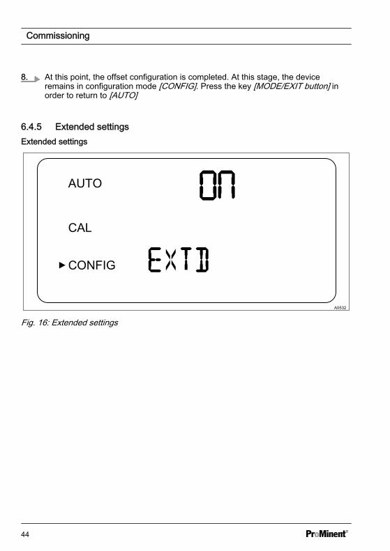
6.4.5 Extended settingsExtended settings
A0532
Fig. 16: Extended settings
Commissioning
44
Function Options Info
Extended settings [ON] (On)
[OFF] (Off)
Select the function"Extended settings" inorder to access configura‐tion for the followingoptions:
n Speed of responsen Screen resolutionn LCD illumination bright‐
nessn Unitsn Ultrasonic cleaningn RS-485 parametersn Alarm drying agent
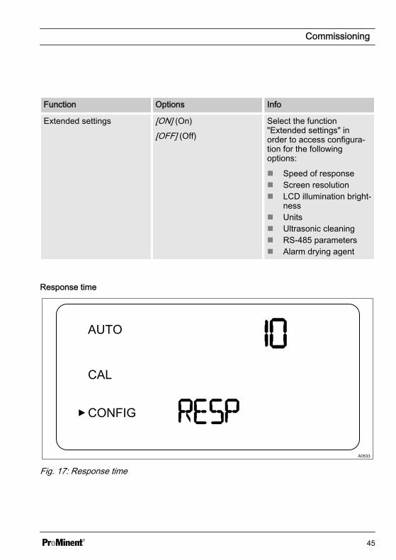
Response time
A0533
Fig. 17: Response time
Commissioning
45
Function Options Info
Reaction time(RESP)
1 ... 100 %
Factory setting: 10 %
Select a reaction time for the displayedand output NTU values.
Select the highest reaction time (i.e. thehighest number) in order to avoid anoma‐lies caused by air or other influences.
Select the lowest reaction time (i.e. thelowest number) if rapid changes are to beexpected, which are to be monitored.
The displayed number is a relative reac‐tion time. The approximate reaction time(in seconds) can be calculated by the dis‐played number multiplied by 5.
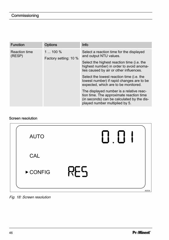
Screen resolution
A0534
Fig. 18: Screen resolution
Commissioning
46
Function Options Info
Screen resolution (RES) 1 ... 0.001
Factory setting: 0,01
For displayed values under10 NTU theDULCO® turb C is able todisplay a value with up tofour digits after the decimalpoint
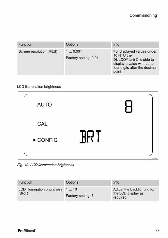
LCD illumination brightness
A0535
Fig. 19: LCD illumination brightness
Function Options Info
LCD illumination brightness(BRT)
1 ... 10
Factory setting: 8
Adjust the backlighting forthe LCD display asrequired
Commissioning
47
Units
A0536
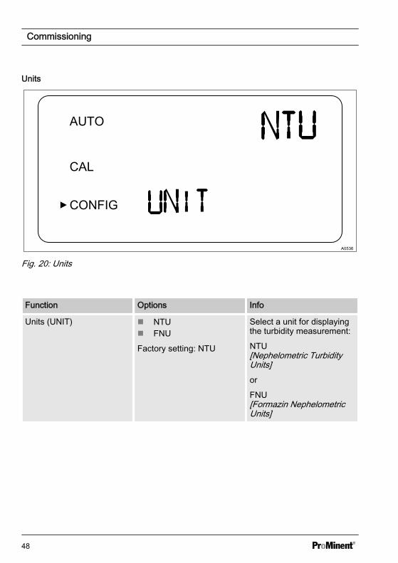
Fig. 20: Units
Function Options Info
Units (UNIT) n NTUn FNU
Factory setting: NTU
Select a unit for displayingthe turbidity measurement:
NTU[Nephelometric TurbidityUnits]or
FNU[Formazin NephelometricUnits]
Commissioning
48
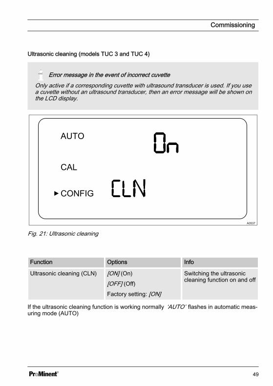
Ultrasonic cleaning (models TUC 3 and TUC 4)
Error message in the event of incorrect cuvetteOnly active if a corresponding cuvette with ultrasound transducer is used. If you usea cuvette without an ultrasound transducer, then an error message will be shown onthe LCD display.
A0537
Fig. 21: Ultrasonic cleaning
Function Options Info
Ultrasonic cleaning (CLN) [ON] (On)
[OFF] (Off)
Factory setting: [ON]
Switching the ultrasoniccleaning function on and off
If the ultrasonic cleaning function is working normally ‘AUTO’ flashes in automatic meas‐uring mode (AUTO)
Commissioning
49
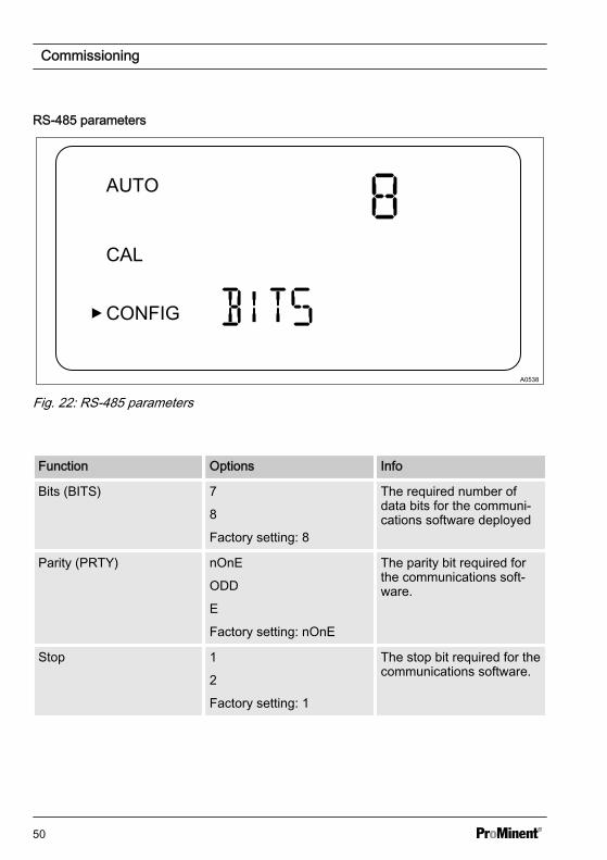
RS-485 parameters
A0538
Fig. 22: RS-485 parameters
Function Options Info
Bits (BITS) 7
8
Factory setting: 8
The required number ofdata bits for the communi‐cations software deployed
Parity (PRTY) nOnE
ODD
E
Factory setting: nOnE
The parity bit required forthe communications soft‐ware.
Stop 1
2
Factory setting: 1
The stop bit required for thecommunications software.
Commissioning
50
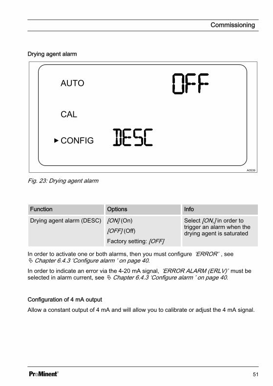
Drying agent alarm
A0539
Fig. 23: Drying agent alarm
Function Options Info
Drying agent alarm (DESC) [ON] (On)
[OFF] (Off)
Factory setting: [OFF]
Select [ON,] in order totrigger an alarm when thedrying agent is saturated
In order to activate one or both alarms, then you must configure ‘ERROR’ , seeÄ Chapter 6.4.3 ‘Configure alarm ’ on page 40.
In order to indicate an error via the 4-20 mA signal, ‘ERROR ALARM (ERLV)’ must beselected in alarm current, see Ä Chapter 6.4.3 ‘Configure alarm ’ on page 40.
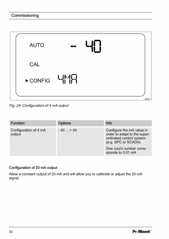
Configuration of 4 mA output
Allow a constant output of 4 mA and will allow you to calibrate or adjust the 4 mA signal.
Commissioning
51
A0607
Fig. 24: Configuration of 4 mA output
Function Options Info
Configuration of 4 mAoutput
- 40 ... + 40 Configure the mA value inorder to adapt to the super‐ordinated control system(e.g. SPC or SCADA)
One count number corre‐sponds to 0.01 mA
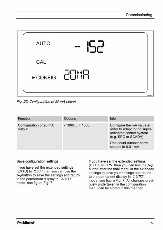
Configuration of 20 mA output
Allow a constant output of 20 mA and will allow you to calibrate or adjust the 20 mAsignal.
Commissioning
52
A0608
Fig. 25: Configuration of 20 mA output
Function Options Info
Configuration of 20 mAoutput
- 1000 ... + 1000 Configure the mA value inorder to adapt to the super‐ordinated control system(e.g. SPC or SCADA)
One count number corre‐sponds to 0.01 mA
Save configuration settings
If you have set the extended settings(EXTD) to ‘OFF’ then you can use the[]-button to save the settings and returnto the permanent display in ‘AUTO’mode, see figure Fig. 7
If you have set the extended settings(EXTD) to ‘ON’ then you can use the []-button after the final menu in the extendedsettings to save your settings and returnto the permanent display in ‘AUTO’mode, see figure Fig. 7. All changes previ‐ously undertaken in the configurationmenu can be stored in this manner.
Commissioning
53
You can access the configuration menu atany time in order to reset or modify someor all of the parameters. You can exit theconfiguration menu at any time bypressing the [MODE/EXIT button] . Indoing so, any changes to the parametersthat you have modified will be stored.
Flow controller
The flow controller (part number 1037880)limits high-pressure systems to a flow ofless than 1 l/min.
Commissioning
54
7 Operation7.1 Calibrating DULCO® turb C
The DULCO® turb C is tested andcalibrated before leaving the factory.For this reason, the DULCO® turb Cmay be used immediately. Undernormal conditions, it is recommendedto carry out calibration at least onceevery three months.If the DULCO® turb C is in [CAL] or[CONFIG] mode, the alarm relaychanges to alarm status. If no input ismade in [CAL]mode within a period of15 minutes, the DULCO® turb C auto‐matically switches back to [AUTO]mode.
7.1.1 Standard solutions for cali‐bration
If the DULCO® turb C is operatedover its complete measuring range of0.02 NTU ... 1000 NTU, you must per‐form calibration with all 3 standardsolutions (0.02 NTU, 10.0 NTU and1000 NTU). If the sensor is only oper‐ated in measurement ranges under10 NTU, then you may perform a sim‐plified calibration with standard solu‐tions 0.02 NTU and 10.0 NTU.
CAUTION!
Use of diluted formazinePossible consequences: Inaccuratecalibration. Malfunctions in dependentprocesses.
Diluted formazine is instable. Ensurethat freshly prepared formazine solu‐tion is used when performing calibra‐tion.
If possible, use a standard solutionfrom Prominent for calibration. Thesestandard solutions are more stablethan formazine and have a minimumshelf-life of 12 months. In doing so,observe the use-by-date on thestandard solution packaging.
Calibration set order number: 1037699
Operation
55
Indexing the standard solution with your cuvette
CAUTION!
Malfunction of the control circuitPossible consequence: Poor end-product quality
Ensure that your controller or other measuring equipment is configured so that theindexing process does not lead to unintentional control functions in the measuringand control system. The controller connected to the DULCO® turb C may not processthe signals issued by the DULCO® turb C and use them for control purposes whilethe signals are being indexed.
NOTICE!
Screen resolutionFor the purposes of indexing, we recommend that the DULCO® turb C should be setin the "Commissioning/solution display" menu so that the following resolutions areobtained
– 1000 NTU: No digits after the decimal point on the display– 10 NTU: Two digits after the decimal point on the display– 0.02 NTU: Four digits after the decimal point on the display
NOTICE!
Freezing of standard solutionThe standard solutions must not freeze. Even for short periods of time.
Operation
56

A0647
Fig. 26: Insert sheet for standard solutions
Handling the standard solutionThe standard solution 1000 NTU must be lightly shaken before use for calibration.Standard solution 10 NTU must be transferred to the cuvette from the storage bottlebefore it is used for the first time. The filling for the 10 NTU cuvette is then usable for24 hours.Do not use the standard solution once the use-by-date has expired.The cuvettes for the 1000 NTU and 0.02 NTU standard solutions may not beopened.
Operation
57
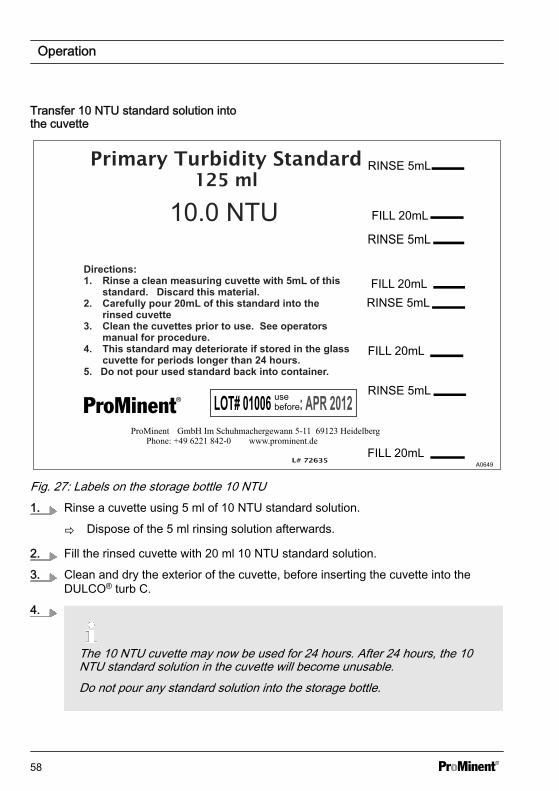
Transfer 10 NTU standard solution intothe cuvette
A0649
Fig. 27: Labels on the storage bottle 10 NTU1. Rinse a cuvette using 5 ml of 10 NTU standard solution.
ð Dispose of the 5 ml rinsing solution afterwards.
2. Fill the rinsed cuvette with 20 ml 10 NTU standard solution.
3. Clean and dry the exterior of the cuvette, before inserting the cuvette into theDULCO® turb C.
4.
The 10 NTU cuvette may now be used for 24 hours. After 24 hours, the 10NTU standard solution in the cuvette will become unusable.Do not pour any standard solution into the storage bottle.
Operation
58
Purpose of indexingThe standard solution cuvettes have a minimal manufacturing tolerance. This manu‐facturing tolerance results from the manufacturing process and is unavoidable.In order to minimise the effects of these manufacturing tolerances on the calibrationprocess, you must index and mark the position on the cuvette with the lowest tur‐bidity value (lowest NTU value).You can mark the index points with the help of the marking rings supplied. Thesemarking rings are included with the calibration set packaging. The marking ring mustfirst be placed around the plastic cover of the respective cuvette.
Operation
59
Prerequisite: The DULCO® turb C is ready for operation and is set to [AUTO] mode.
1. Open the flow unit by screwing it clockwise and remove the in-line flow fitting fromthe cuvette.
2. Insert the [1000 NTU] calibration cuvette into the DULCO® turb C.
3. Turn the [1000 NTU] calibration cuvette one full turn in 20° steps. At each step,wait until the displayed measured value has stabilised.
ð Mark the point on the cuvette with the lowest NTU value with the help of themarking ring supplied, so that the marker points towards yourself.
4. Remove the [1000 NTU] calibration cuvette and insert the [10 NTU] calibrationcuvette into the DULCO® turb C.
5. Turn the [10 NTU] calibration cuvette one full turn in 20° steps. At each step, waituntil the displayed measured value has stabilised.
ð Mark the point on the cuvette with the lowest NTU value with the help of themarking ring supplied, so that the marker points towards yourself.
6. Remove the [10 NTU] calibration cuvette and insert the [0.02 NTU] calibration cuv‐ette into the DULCO® turb C.
7. Turn the [0.02 NTU] calibration cuvette one full turn in 20° steps. At each step, waituntil the displayed measured value has stabilised.
ð Mark the point on the cuvette with the lowest NTU value with the help of themarking ring supplied, so that the marker points towards yourself.
8. Insert the cuvette sample with the cuvette into the DULCO® turb C.
9. Close the in-line flow fitting by screwing it in an anticlockwise direction.
ð The DULCO® turb C will be in [AUTO] mode.
For subsequent calibration, insert the calibration cuvettes into theDULCO® turb C so that the marker on the marking ring faces towards you.
Operation
60
7.1.2 Perform calibration
CAUTION!
Malfunction of the control circuitPossible consequence: Poor end-product quality
Ensure that your controller or other measuring equipment is configured so that thecalibration process does not lead to unintentional control functions in the measure‐ment and control system. The controller connected to the DULCO® turb C may notprocess the signals issued by the DULCO® turb C and use them for control purposeswhile the signals are being indexed.
NOTICE!
Fan standstillThe DULCO® turb C fan is switched off during the calibration process, in order toextend the service life of the drying agent.
The fan is switched on:
– During the calibration countdown– After returning to [AUTO] mode– After 5 minutes without input from the operator
– Whichever occurs first.
Keep the measurement chamber covered if no cuvette is inserted and only place acuvette into the measurement chamber if it is completely dry, in order to avoid pre‐mature saturation of the drying agent.
NOTICE!
Cleaning and drying the cuvettePossibility measurement value distortion.
Before each cuvette is inserted, it must be thoroughly cleaned and dried with thecleaning cloth provided with the calibration set. Even minimal traces of foreign bodiesand moisture on the surface of the cuvette can cause the measured result to be falsi‐fied.
Operation
61
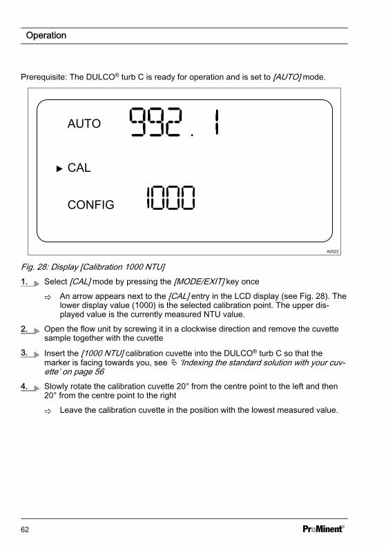
Prerequisite: The DULCO® turb C is ready for operation and is set to [AUTO] mode.
Fig. 28: Display [Calibration 1000 NTU]1. Select [CAL] mode by pressing the [MODE/EXIT] key once
ð An arrow appears next to the [CAL] entry in the LCD display (see Fig. 28). Thelower display value (1000) is the selected calibration point. The upper dis‐played value is the currently measured NTU value.
2. Open the flow unit by screwing it in a clockwise direction and remove the cuvettesample together with the cuvette
3. Insert the [1000 NTU] calibration cuvette into the DULCO® turb C so that themarker is facing towards you, see Ä ‘Indexing the standard solution with your cuv‐ette’ on page 56
4. Slowly rotate the calibration cuvette 20° from the centre point to the left and then20° from the centre point to the right
ð Leave the calibration cuvette in the position with the lowest measured value.
Operation
62
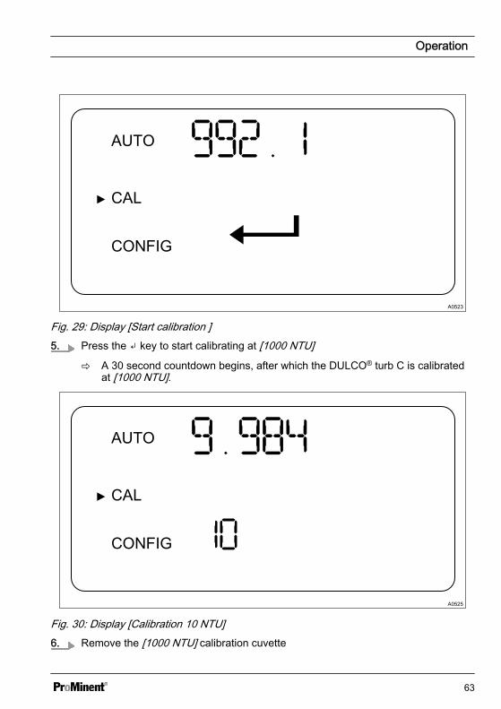
A0523
Fig. 29: Display [Start calibration ]5. Press the key to start calibrating at [1000 NTU]
ð A 30 second countdown begins, after which the DULCO® turb C is calibratedat [1000 NTU].
A0525
Fig. 30: Display [Calibration 10 NTU]6. Remove the [1000 NTU] calibration cuvette
Operation
63
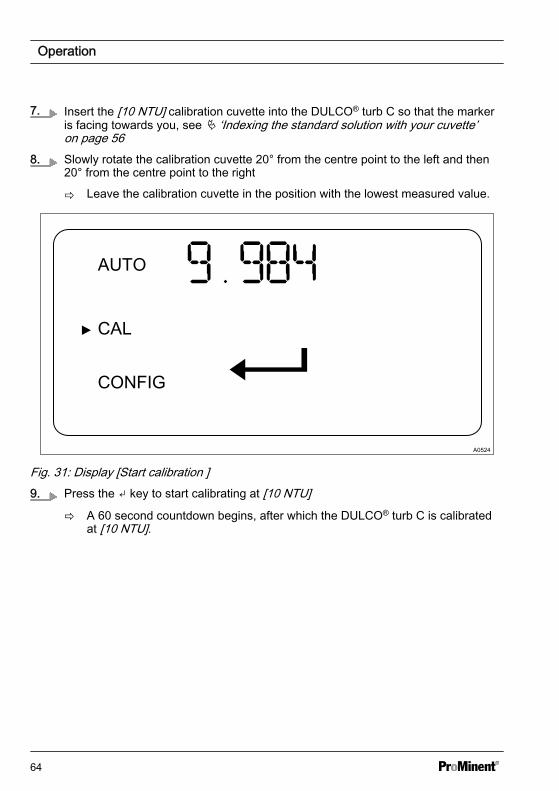
7. Insert the [10 NTU] calibration cuvette into the DULCO® turb C so that the markeris facing towards you, see Ä ‘Indexing the standard solution with your cuvette’on page 56
8. Slowly rotate the calibration cuvette 20° from the centre point to the left and then20° from the centre point to the right
ð Leave the calibration cuvette in the position with the lowest measured value.
A0524
Fig. 31: Display [Start calibration ]9. Press the key to start calibrating at [10 NTU]
ð A 60 second countdown begins, after which the DULCO® turb C is calibratedat [10 NTU].
Operation
64
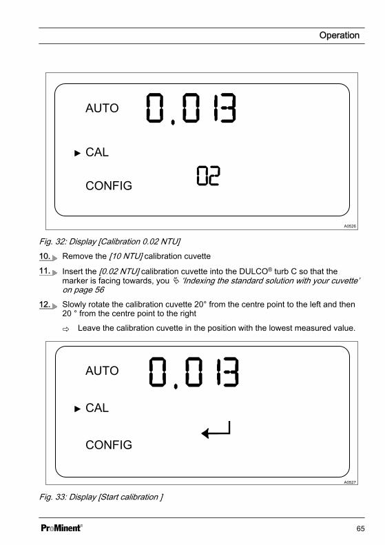
A0526
Fig. 32: Display [Calibration 0.02 NTU]10. Remove the [10 NTU] calibration cuvette
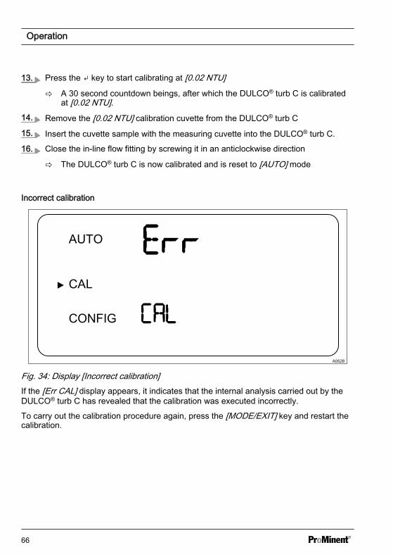
11. Insert the [0.02 NTU] calibration cuvette into the DULCO® turb C so that themarker is facing towards, you Ä ‘Indexing the standard solution with your cuvette’on page 56
12. Slowly rotate the calibration cuvette 20° from the centre point to the left and then20 ° from the centre point to the right
ð Leave the calibration cuvette in the position with the lowest measured value.
A0527
Fig. 33: Display [Start calibration ]
Operation
65
13. Press the key to start calibrating at [0.02 NTU]
ð A 30 second countdown beings, after which the DULCO® turb C is calibratedat [0.02 NTU].
14. Remove the [0.02 NTU] calibration cuvette from the DULCO® turb C
15. Insert the cuvette sample with the measuring cuvette into the DULCO® turb C.
16. Close the in-line flow fitting by screwing it in an anticlockwise direction
ð The DULCO® turb C is now calibrated and is reset to [AUTO] mode
Incorrect calibration
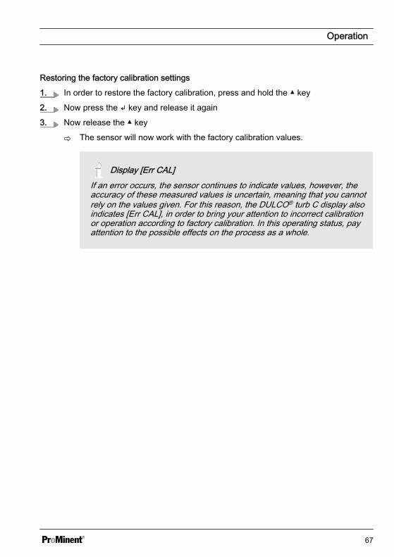
A0528
Fig. 34: Display [Incorrect calibration]If the [Err CAL] display appears, it indicates that the internal analysis carried out by theDULCO® turb C has revealed that the calibration was executed incorrectly.
To carry out the calibration procedure again, press the [MODE/EXIT] key and restart thecalibration.
Operation
66
Restoring the factory calibration settings
1. In order to restore the factory calibration, press and hold the key
2. Now press the key and release it again
3. Now release the key
ð The sensor will now work with the factory calibration values.
Display [Err CAL]If an error occurs, the sensor continues to indicate values, however, theaccuracy of these measured values is uncertain, meaning that you cannotrely on the values given. For this reason, the DULCO® turb C display alsoindicates [Err CAL], in order to bring your attention to incorrect calibrationor operation according to factory calibration. In this operating status, payattention to the possible effects on the process as a whole.
Operation
67
8 Maintenance, troubleshooting and repair8.1 Information about trouble‐
shootingThe DULCO® turb C also carries out gen‐eral self-diagnosis. Any errors are dis‐played in the bottom row of the display.
The DULCO® turb C operates three-stagefault detection:
n Warning, e.g. [DESC]– A warning is merely a message
on the display which serves toindicate a pending problem. Noalarms are issued. If, forexample, the drying agent alarmis deactivated and the dryingagent is saturated, the LCD dis‐play shows the warning [DESC]
n Error [Err]– An error [Err] indicates a malfunc‐
tion or problem which can gener‐ally be rectified by the operator.This includes, for example, alamp failure [LAMP] or incorrectcalibration [CAL]. If an erroroccurs, the sensor continues toindicate values, however, theaccuracy of these measuredvalues is uncertain, meaning thatyou cannot rely on the valuesgiven.
n Fault [FAIL]– A fault [FAIL] is a system error.
This problem cannot be rectifiedby the operator. TheDULCO® turb C must be sentback to the factory for repair.These faults are faults in the[CPU], [A/D], [EEPROM] or otherunits built into theDULCO® turb C. In the event of amalfunction, the DULCO® turb C
will not function correctly and the[FAIL] message will appear in theLCD display. Both alarm relaysare activated and the currentoutput is set to 2 mA.
Maintenance, troubleshooting and repair
68
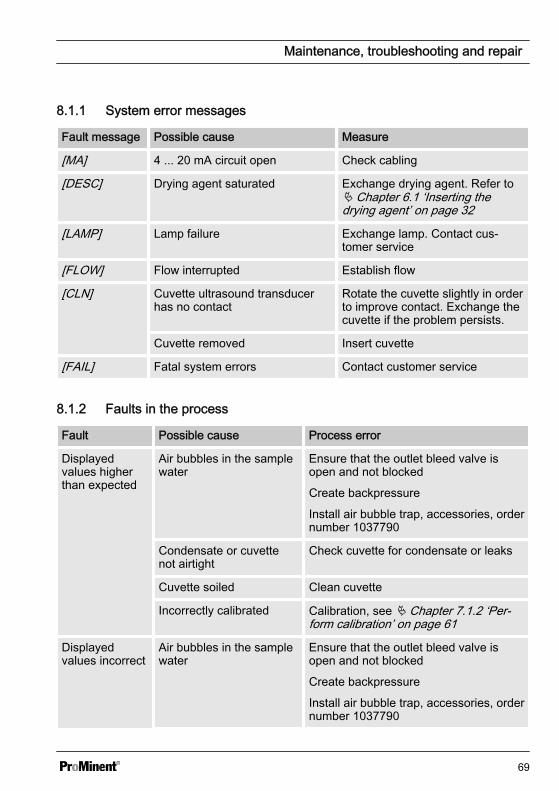
8.1.1 System error messages
Fault message Possible cause Measure
[MA] 4 ... 20 mA circuit open Check cabling
[DESC] Drying agent saturated Exchange drying agent. Refer toÄ Chapter 6.1 ‘Inserting thedrying agent’ on page 32
[LAMP] Lamp failure Exchange lamp. Contact cus‐tomer service
[FLOW] Flow interrupted Establish flow
[CLN] Cuvette ultrasound transducerhas no contact
Rotate the cuvette slightly in orderto improve contact. Exchange thecuvette if the problem persists.
Cuvette removed Insert cuvette
[FAIL] Fatal system errors Contact customer service
8.1.2 Faults in the process
Fault Possible cause Process error
Displayedvalues higherthan expected
Air bubbles in the samplewater
Ensure that the outlet bleed valve isopen and not blocked
Create backpressure
Install air bubble trap, accessories, ordernumber 1037790
Condensate or cuvettenot airtight
Check cuvette for condensate or leaks
Cuvette soiled Clean cuvette
Incorrectly calibrated Calibration, see Ä Chapter 7.1.2 ‘Per‐form calibration’ on page 61
Displayedvalues incorrect
Air bubbles in the samplewater
Ensure that the outlet bleed valve isopen and not blocked
Create backpressure
Install air bubble trap, accessories, ordernumber 1037790
Maintenance, troubleshooting and repair
69
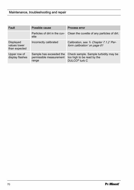
Fault Possible cause Process error
Particles of dirt in the cuv‐ette
Clean the cuvette of any particles of dirt.
Displayedvalues lowerthan expected
Incorrectly calibrated Calibration, see Ä Chapter 7.1.2 ‘Per‐form calibration’ on page 61
Upper row ofdisplay flashes
Sample has exceeded thepermissible measurementrange
Check sample. Sample turbidity may betoo high to be read by theDULCO® turb C
Maintenance, troubleshooting and repair
70
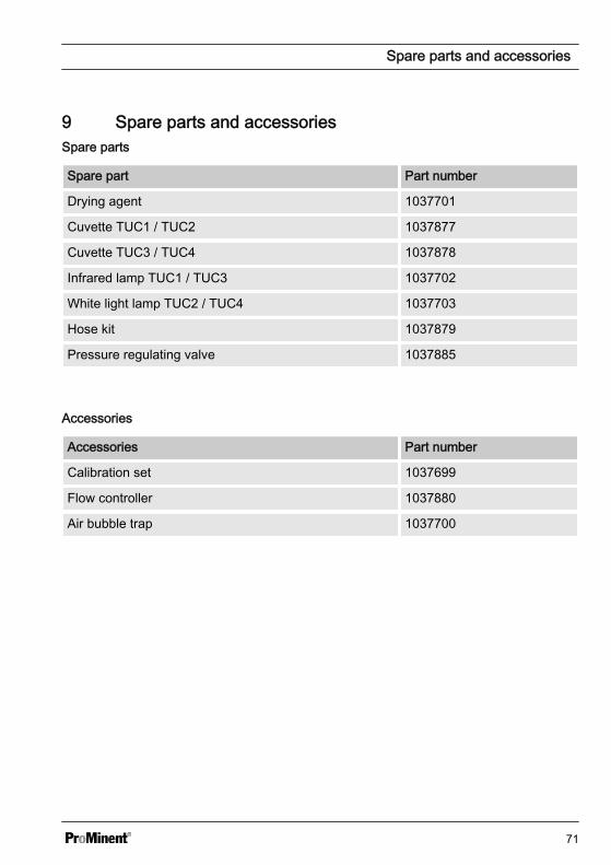
9 Spare parts and accessoriesSpare parts
Spare part Part number
Drying agent 1037701
Cuvette TUC1 / TUC2 1037877
Cuvette TUC3 / TUC4 1037878
Infrared lamp TUC1 / TUC3 1037702
White light lamp TUC2 / TUC4 1037703
Hose kit 1037879
Pressure regulating valve 1037885
Accessories
Accessories Part number
Calibration set 1037699
Flow controller 1037880
Air bubble trap 1037700
Spare parts and accessories
71

10 Disposal of Used Partsn User qualification: instructed user,
see Ä Chapter 1.2 ‘Users' qualifica‐tions’ on page 8
NOTICE!
Regulations governing the disposal ofused parts– Note the national regulations and
legal standards that currentlyapply in your country
The manufacturer will take back decon‐taminated used units providing they arecovered by adequate postage.
Decontaminate the unit before returning itfor repair. To do so, remove all traces ofhazardous substances. Refer to the Mate‐rial Safety Data Sheet for your feed chem‐ical.
A current Declaration of Decontaminationis available to download on the ProMinentwebsite.
Disposal of Used Parts
72
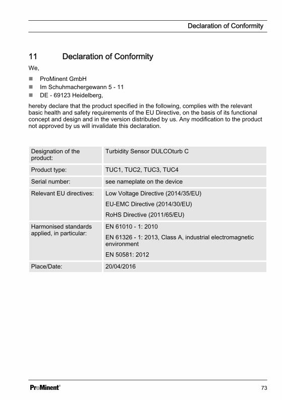
11 Declaration of ConformityWe,
n ProMinent GmbHn Im Schuhmachergewann 5 - 11n DE - 69123 Heidelberg,
hereby declare that the product specified in the following, complies with the relevantbasic health and safety requirements of the EU Directive, on the basis of its functionalconcept and design and in the version distributed by us. Any modification to the productnot approved by us will invalidate this declaration.
Designation of theproduct:
Turbidity Sensor DULCOturb C
Product type: TUC1, TUC2, TUC3, TUC4
Serial number: see nameplate on the device
Relevant EU directives: Low Voltage Directive (2014/35/EU)
EU-EMC Directive (2014/30/EU)
RoHS Directive (2011/65/EU)
Harmonised standardsapplied, in particular:
EN 61010 - 1: 2010
EN 61326 - 1: 2013, Class A, industrial electromagneticenvironment
EN 50581: 2012
Place/Date: 20/04/2016
Declaration of Conformity
73
12 IndexAAccessibility . . . . . . . . . . . . . . . . . . . 16Accessories . . . . . . . . . . . . . . . . . . . 71Action, step by step . . . . . . . . . . . . . . 2Alarm delay period . . . . . . . . . . . . . . 40Alarm ERROR . . . . . . . . . . . . . . . . . 40Alarm function . . . . . . . . . . . . . . . . . 40Alarm HI . . . . . . . . . . . . . . . . . . . . . 40Alarm limit value . . . . . . . . . . . . . . . . 40Alarm LO . . . . . . . . . . . . . . . . . . . . 40Alarm menu . . . . . . . . . . . . . . . . . . . 41Ambient temperature . . . . . . . . . . . . 16Applied harmonised standards . . . . . . 73
CCalibration erroneous . . . . . . . . . . . . 66
DData . . . . . . . . . . . . . . . . . . . . . . . . . 6Degree of protection IP 66 . . . . . . . . 26Delay period alarm . . . . . . . . . . . . . . 40Designation of the product . . . . . . . . . 73
FFlow . . . . . . . . . . . . . . . . . . . . . . . . 20FNU . . . . . . . . . . . . . . . . . . . . . . . . 31Functions . . . . . . . . . . . . . . . . . . . . . 6
GGeneral non-discriminatory approach . . 2
IIncorrect calibration . . . . . . . . . . . . . 66
LLimit value alarm . . . . . . . . . . . . . . . 40Links to elements or sections of theseinstructions or other applicable docu‐ments . . . . . . . . . . . . . . . . . . . . . . . . 2
Liquid temperature . . . . . . . . . . . . . . 20
MMenu Alarm . . . . . . . . . . . . . . . . . . . 41More symbols . . . . . . . . . . . . . . . . . . 2Mounting position . . . . . . . . . . . . . . . 16
NNon-discriminatory approach . . . . . . . . 2NTU . . . . . . . . . . . . . . . . . . . . . . . . 31
OOperating position . . . . . . . . . . . . . . 16
PPressure . . . . . . . . . . . . . . . . . . . . . 20
RReading position . . . . . . . . . . . . . . . 16Recycling . . . . . . . . . . . . . . . . . . 15, 16Relevant EU directives . . . . . . . . . . . 73
SSerial number . . . . . . . . . . . . . . . . . 73Spare parts . . . . . . . . . . . . . . . . . . . 71Strain relief . . . . . . . . . . . . . . . . . . . 23Sunlight . . . . . . . . . . . . . . . . . . . . . 16
TTurbidity threshold . . . . . . . . . . . . . . 40
UUnit NTU . . . . . . . . . . . . . . . . . . . . . 31Users' qualifications . . . . . . . . . . . . . . 8
WWarning information . . . . . . . . . . . . . . 6
Index
74

75

986062, 2, en_GB
© 2016
ProMinent GmbHIm Schuhmachergewann 5 - 1169123 Heidelberg, GermanyTelephone: +49 6221 842-0Fax: +49 6221 842-419Email: [email protected]: www.prominent.com