duplex filter with filter element according to din 24550 - epg · re 51453, edition: 2013-12, bosch...
TRANSCRIPT
RE 51453, edition: 2013-12, Bosch Rexroth AG
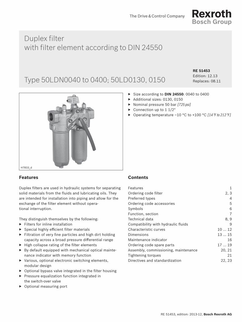
Duplex filter with filter element according to DIN 24550
▶ Size according to DIN 24550: 0040 to 0400 ▶ Additional sizes: 0130, 0150 ▶ Nominal pressure 50 bar [725 psi] ▶ Connection up to 1 1/2" ▶ Operating temperature –10 °C to +100 °C [14 °F to 212 °F]
RE 51453 Edition: 12.13Replaces: 08.11Type 50LDN0040 to 0400; 50LD0130, 0150
Contents
Features 1Ordering code fi lter 2, 3Preferred types 4Ordering code accessories 5Symbols 6Function, section 7Technical data 8, 9Compatibility with hydraulic fl uids 9Characteristic curves 10 … 12Dimensions 13 … 15Maintenance indicator 16Ordering code spare parts 17 ... 19Assembly, commissioning, maintenance 20, 21Tightening torques 21 Directives and standardization 22, 23
H7833_d
Features
Duplex filters are used in hydraulic systems for separating solid materials from the fluids and lubricating oils. They are intended for installation into piping and allow for the exchange of the filter element without opera-tional interruption.
They distinguish themselves by the following: ▶ Filters for inline installation ▶ Special highly effi cient fi lter materials ▶ Filtration of very fi ne particles and high dirt holding
capacity across a broad pressure diff erential range ▶ High collapse rating of the fi lter elements ▶ By default equipped with mechanical optical mainte-
nance indicator with memory function ▶ Various, optional electronic switching elements,
modular design ▶ Optional bypass valve integrated in the fi lter housing ▶ Pressure equalization function integrated in
the switch-over valve ▶ Optional measuring port
2/24 50LDN0040-0400; 50LD0130, 0150 | RE 51453
Bosch Rexroth AG, RE 51453, edition: 2013-12
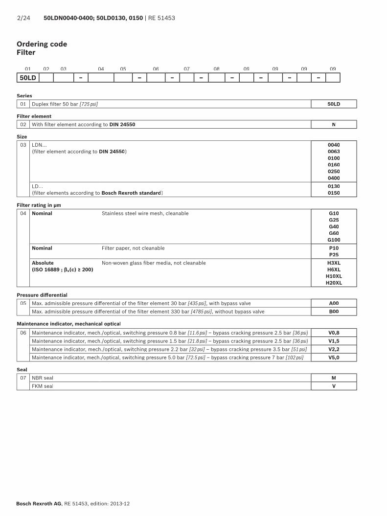
Ordering code Filter
Series01 Duplex fi lter 50 bar [725 psi] 50LD
Filter element02 With fi lter element according to DIN 24550 N
Size03 LDN...
(fi lter element according to DIN 24550)004000630100016002500400
LD... (fi lter elements according to Bosch Rexroth standard)
01300150
Filter rating in µm04 Nominal Stainless steel wire mesh, cleanable G10
G25G40G60G100
Nominal Filter paper, not cleanable P10P25
Absolute(ISO 16889 ; βx(c) ≥ 200)
Non-woven glass fi ber media, not cleanable H3XLH6XL
H10XLH20XL
Pressure diff erential05 Max. admissible pressure diff erential of the fi lter element 30 bar [435 psi], with bypass valve A00
Max. admissible pressure diff erential of the fi lter element 330 bar [4785 psi], without bypass valve B00
Maintenance indicator, mechanical optical06 Maintenance indicator, mech./optical, switching pressure 0.8 bar [11.6 psi] – bypass cracking pressure 2.5 bar [36 psi] V0,8
Maintenance indicator, mech./optical, switching pressure 1.5 bar [21.8 psi] – bypass cracking pressure 2.5 bar [36 psi] V1,5Maintenance indicator, mech./optical, switching pressure 2.2 bar [32 psi] – bypass cracking pressure 3.5 bar [51 psi] V2,2Maintenance indicator, mech./optical, switching pressure 5.0 bar [72.5 psi] – bypass cracking pressure 7 bar [102 psi] V5,0
Seal07 NBR seal M
FKM seal V
01 02 03 04 05 06 07 08 09 09 09 09
50LD – – – – – – – –
RE 51453 | 50LDN0040-0400; 50LD0130, 0150 3/24
RE 51453, edition: 2013-12, Bosch Rexroth AG
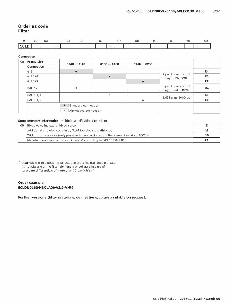
Ordering codeFilter
01 02 03 04 05 06 07 08 09 09 09 09
50LD – – – – – – – –
Connection08 Frame size
0040 ... 0100 0130 ... 0150 0160 ... 0250ConnectionG 1 ●
Pipe thread accord-ing to ISO 228
R4G 1 1/4 ● R5G 1 1/2 ● R6
SAE 12 X Pipe thread accord-ing to SAE J1926 U4
SAE 1 1/4" XSAE fl ange 3000 psi
S5SAE 1 1/2" X S6
● Standard connectionX Alternative connection
Supplementary information (multiple specifi cations possible)09 Bleed valve instead of bleed screw E
Additional threaded couplings, G1/4 top clean and dirt side MWithout bypass valve (only possible in connection with fi lter element version "A00") 1) NBManufacturer's inspection certifi cate M according to DIN 55350 T18 Z1
Order example:50LDN0160-H3XLA00-V2,2-M-R6
Further versions (fi lter materials, connections,...) are available on request.
1) Attention: If this option is selected and the maintenance indicator is not observed, the filter element may collapse in case of pressure differentials of more than 30 bar [435 psi].
4/24 50LDN0040-0400; 50LD0130, 0150 | RE 51453
Bosch Rexroth AG, RE 51453, edition: 2013-12
Preferred types
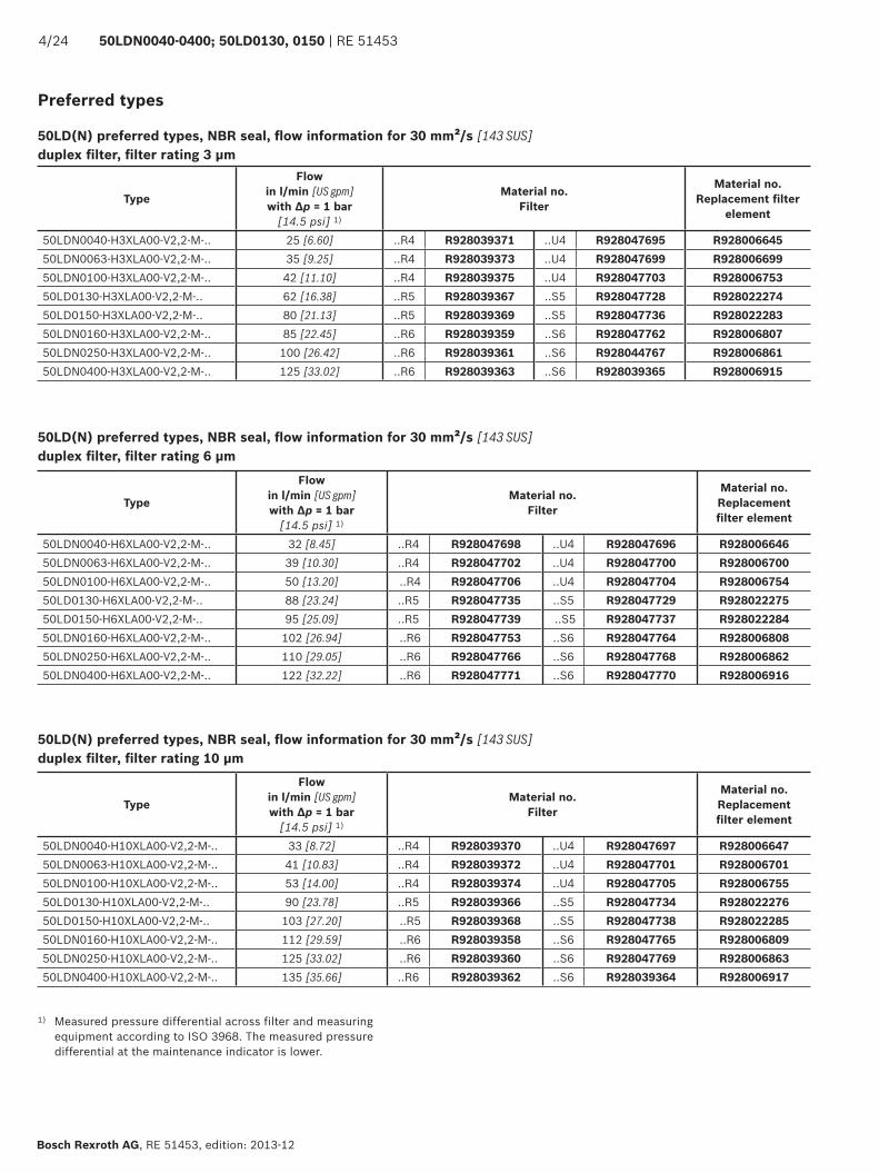
50LD(N) preferred types, NBR seal, fl ow information for 30 mm²/s [143 SUS]duplex fi lter, fi lter rating 3 μm
50LD(N) preferred types, NBR seal, fl ow information for 30 mm²/s [143 SUS]duplex fi lter, fi lter rating 6 μm
50LD(N) preferred types, NBR seal, fl ow information for 30 mm²/s [143 SUS]duplex fi lter, fi lter rating 10 μm
Type
Flow in l/min [US gpm] with Δp = 1 bar
[14.5 psi] 1)
Material no.Filter
Material no.Replacement fi lter
element
50LDN0040-H3XLA00-V2,2-M-.. 25 [6.60] ..R4 R928039371 ..U4 R928047695 R92800664550LDN0063-H3XLA00-V2,2-M-.. 35 [9.25] ..R4 R928039373 ..U4 R928047699 R92800669950LDN0100-H3XLA00-V2,2-M-.. 42 [11.10] ..R4 R928039375 ..U4 R928047703 R92800675350LD0130-H3XLA00-V2,2-M-.. 62 [16.38] ..R5 R928039367 ..S5 R928047728 R92802227450LD0150-H3XLA00-V2,2-M-.. 80 [21.13] ..R5 R928039369 ..S5 R928047736 R92802228350LDN0160-H3XLA00-V2,2-M-.. 85 [22.45] ..R6 R928039359 ..S6 R928047762 R92800680750LDN0250-H3XLA00-V2,2-M-.. 100 [26.42] ..R6 R928039361 ..S6 R928044767 R92800686150LDN0400-H3XLA00-V2,2-M-.. 125 [33.02] ..R6 R928039363 ..S6 R928039365 R928006915
1) Measured pressure differential across filter and measuring equipment according to ISO 3968. The measured pressure differential at the maintenance indicator is lower.
Type
Flow in l/min [US gpm] with Δp = 1 bar
[14.5 psi] 1)
Material no.Filter
Material no.Replacement fi lter element
50LDN0040-H6XLA00-V2,2-M-.. 32 [8.45] ..R4 R928047698 ..U4 R928047696 R92800664650LDN0063-H6XLA00-V2,2-M-.. 39 [10.30] ..R4 R928047702 ..U4 R928047700 R92800670050LDN0100-H6XLA00-V2,2-M-.. 50 [13.20] ..R4 R928047706 ..U4 R928047704 R92800675450LD0130-H6XLA00-V2,2-M-.. 88 [23.24] ..R5 R928047735 ..S5 R928047729 R92802227550LD0150-H6XLA00-V2,2-M-.. 95 [25.09] ..R5 R928047739 ..S5 R928047737 R92802228450LDN0160-H6XLA00-V2,2-M-.. 102 [26.94] ..R6 R928047753 ..S6 R928047764 R92800680850LDN0250-H6XLA00-V2,2-M-.. 110 [29.05] ..R6 R928047766 ..S6 R928047768 R92800686250LDN0400-H6XLA00-V2,2-M-.. 122 [32.22] ..R6 R928047771 ..S6 R928047770 R928006916
Type
Flow in l/min [US gpm] with Δp = 1 bar
[14.5 psi] 1)
Material no.Filter
Material no.Replacement fi lter element
50LDN0040-H10XLA00-V2,2-M-.. 33 [8.72] ..R4 R928039370 ..U4 R928047697 R92800664750LDN0063-H10XLA00-V2,2-M-.. 41 [10.83] ..R4 R928039372 ..U4 R928047701 R92800670150LDN0100-H10XLA00-V2,2-M-.. 53 [14.00] ..R4 R928039374 ..U4 R928047705 R92800675550LD0130-H10XLA00-V2,2-M-.. 90 [23.78] ..R5 R928039366 ..S5 R928047734 R92802227650LD0150-H10XLA00-V2,2-M-.. 103 [27.20] ..R5 R928039368 ..S5 R928047738 R92802228550LDN0160-H10XLA00-V2,2-M-.. 112 [29.59] ..R6 R928039358 ..S6 R928047765 R92800680950LDN0250-H10XLA00-V2,2-M-.. 125 [33.02] ..R6 R928039360 ..S6 R928047769 R92800686350LDN0400-H10XLA00-V2,2-M-.. 135 [35.66] ..R6 R928039362 ..S6 R928039364 R928006917
!"#
$%&'
&$
($)
*+
!"#$"%
!&#'
'%
#$%
&'&$
($)
*+
"$*! !$#()%
!&#'
'%
RE 51453 | 50LDN0040-0400; 50LD0130, 0150 5/24
RE 51453, edition: 2013-12, Bosch Rexroth AG
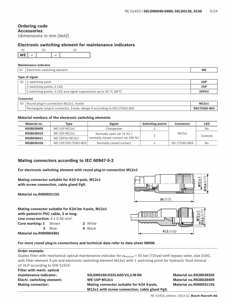
Ordering codeAccessories(dimensions in mm [inch])
Electronic switching element for maintenance indicators
Maintenance indicator01 Electronic switching element WE
Type of signal02 1 switching point 1SP
2 switching points, 3 LED 2SP2 switching points, 3 LED and signal suppression up to 30 °C [86 °F] 2SPSU
Connector03 Round plug-in connection M12x1, 4-pole M12x1
Rectangular plug-in connector, 2-pole, design A according to EN-175301-803 EN175301-803
01 02 03
WE – –
Material numbers of the electronic switching elementsMaterial no. Type Signal Switching points Connector LEDR928028409 WE-1SP-M12x1 Changeover 1
M12x1No
R928028410 WE-2SP-M12x1 Normally open (at 75 %) / normally closed contact (at 100 %) 2 3 pieces
R928028411 WE-2SPSU-M12x1R928036318 WE-1SP-EN175301-803 Normally closed contact 1 EN 175301-803 No
Order example:Duplex filter with mechanical optical maintenance indicator for pNominal = 50 bar [725 psi] with bypass valve, size 0160, with filter element 3 μm and electronic switching element M12x1 with 1 switching point for hydraulic fluid mineral oil HLP according to DIN 51524.Filter with mech. optical maintenance indicator: 50LDN0160-H3XLA00-V2,2-M-R6 Material no.R928039359Electr. switching element: WE-1SP-M12x1 Material no.R928028409Mating connector: Mating connector suitable for K24 4-pole,
M12x1 with screw connection, cable gland Pg9.Material no.R900031155
Mating connectors according to IEC 60947-5-2
Mating connector suitable for K24 4-pole, M12x1 with screw connection, cable gland Pg9.
Material no.R900031155
For electronic switching element with round plug-in connection M12x1
Mating connector suitable for K24-3m 4-pole, M12x1 with potted-in PVC cable, 3 m long.Line cross-section: 4 x 0.34 mm2
Core marking: 1 Brown 2 White 3 Blue 4 BlackMaterial no.R900064381
For more round plug-in connections and technical data refer to data sheet 08006.
$,,-%".!-
$/01
2/31
%4%$,,-
"
4$.!- $/01
2/314%4$
5$.!- 5%6$,,-
%"
$/01
2/31
%
$/01
7
8
7
8
6/24 50LDN0040-0400; 50LD0130, 0150 | RE 51453
Bosch Rexroth AG, RE 51453, edition: 2013-12
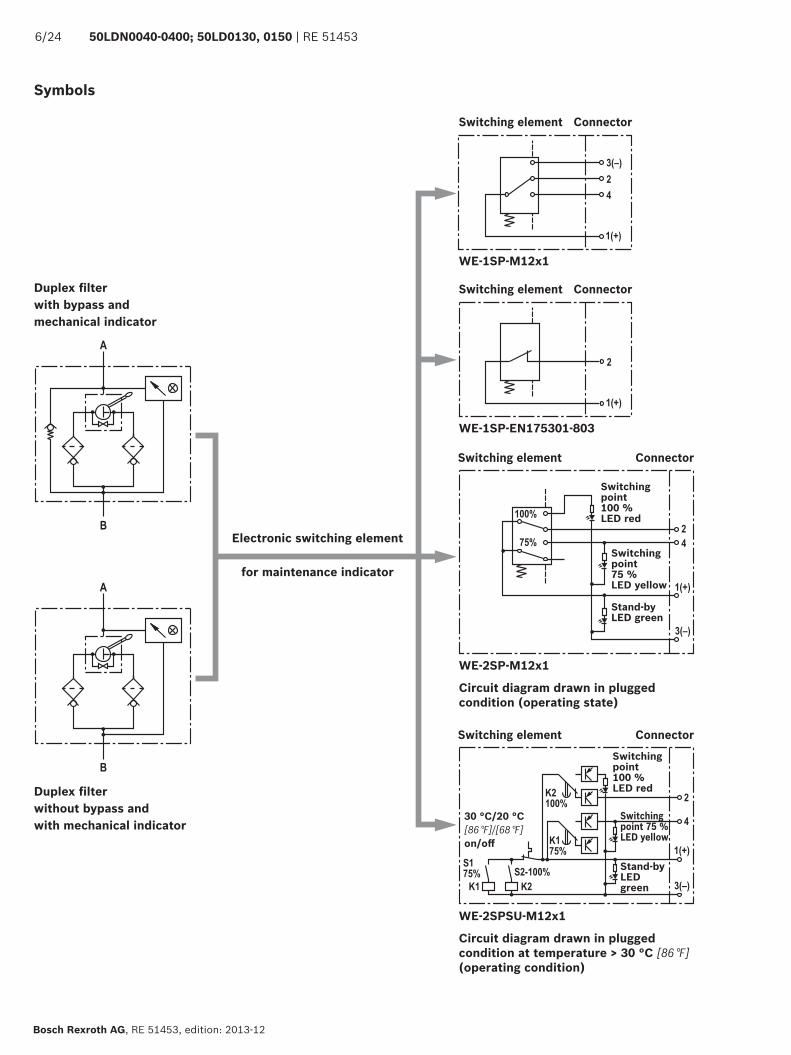
Symbols
Electronic switching element
for maintenance indicator
Duplex fi lter with bypass and mechanical indicator
Duplex fi lter without bypass and with mechanical indicator
Switching element
Switching element
Switching element
Switching element
WE-1SP-M12x1
WE-1SP-EN175301-803
WE-2SP-M12x1
Circuit diagram drawn in plugged condition (operating state)
WE-2SPSU-M12x1
Circuit diagram drawn in plugged condition at temperature > 30 °C [86 °F] (operating condition)
Connector
Connector
Connector
Connector
Switching point100 % LED red
Switching point 100 %LED red
Switching point75 %LED yellow
Switching point 75 %LED yellow
Stand-byLED green
Stand-byLED green
30 °C/20 °C[86 °F]/[68 °F] on/off
!
"
#
$
%
&
'
(
)
"*
RE 51453 | 50LDN0040-0400; 50LD0130, 0150 7/24
RE 51453, edition: 2013-12, Bosch Rexroth AG
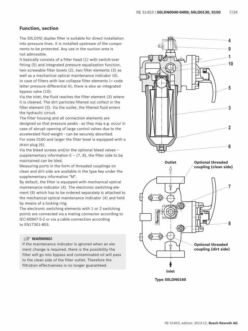
Inlet
Outlet
Type 50LDN0160
The 50LD(N) duplex filter is suitable for direct installation into pressure lines. It is installed upstream of the compo-nents to be protected. Any use in the suction area is not admissible.It basically consists of a filter head (1) with switch-over fitting (5) and integrated pressure equalization function, two screwable filter bowls (2), two filter elements (3) as well as a mechanical optical maintenance indicator (4).In case of filters with low collapse filter elements (= code letter pressure differential A), there is also an integrated bypass valve (10).Via the inlet, the fluid reaches the filter element (3) where it is cleaned. The dirt particles filtered out collect in the filter element (3). Via the outlet, the filtered fluid enters the hydraulic circuit.The filter housing and all connection elements are designed so that pressure peaks - as they may e.g. occur in case of abrupt opening of large control valves due to the accelerated fluid weight - can be securely absorbed.For sizes 0160 and larger the filter bowl is equipped with a drain plug (6).Via the bleed screws and/or the optional bleed valves – supplementary information E – (7, 8), the filter side to be maintained can be bled.Measuring ports in the form of threaded couplings on clean and dirt side are available in the type key under the supplementary information "M".By default, the filter is equipped with mechanical optical maintenance indicator (4). The electronic switching ele-ment (9) which has to be ordered separately is attached to the mechanical optical maintenance indicator (4) and held by means of a locking ring.The electronic switching elements with 1 or 2 switching points are connected via a mating connector according to IEC-60947-5-2 or via a cable connection according to EN17301-803.
Function, section
Optional threaded coupling (clean side)
Optional threaded coupling (dirt side)
WARNING! If the maintenance indicator is ignored when an ele-ment change is required, there is the possibility the filter will go into bypass and contaminated oil will pass to the clean side of the filter outlet. Therefore the filtration effectiveness is no longer guaranteed.
8/24 50LDN0040-0400; 50LD0130, 0150 | RE 51453
Bosch Rexroth AG, RE 51453, edition: 2013-12
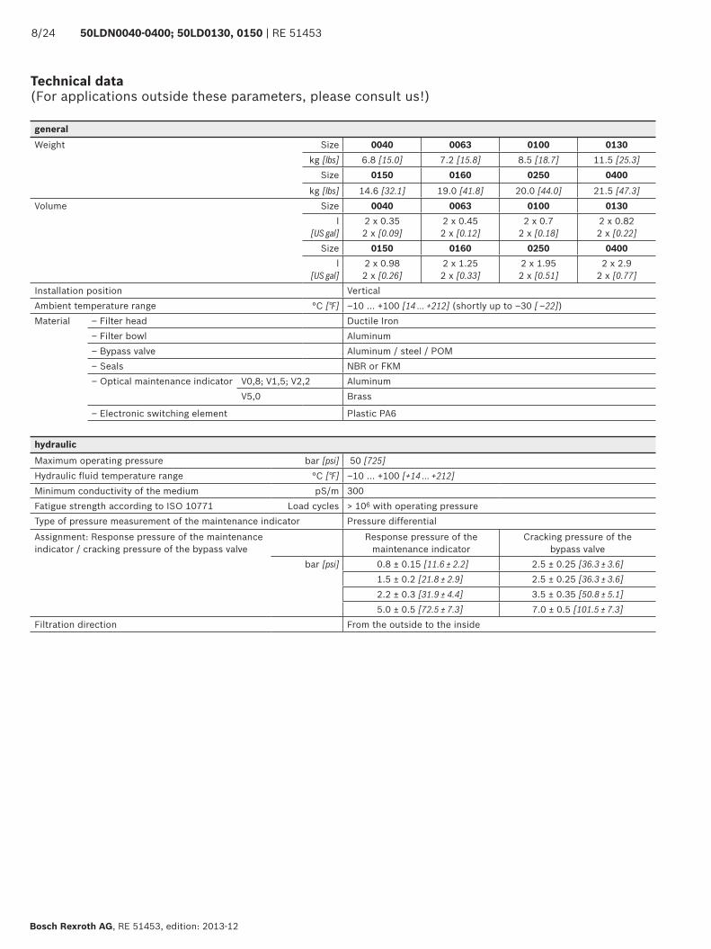
Technical data(For applications outside these parameters, please consult us!)
generalWeight Size 0040 0063 0100 0130
kg [lbs] 6.8 [15.0] 7.2 [15.8] 8.5 [18.7] 11.5 [25.3]Size 0150 0160 0250 0400
kg [lbs] 14.6 [32.1] 19.0 [41.8] 20.0 [44.0] 21.5 [47.3]Volume Size 0040 0063 0100 0130
l [US gal]
2 x 0.352 x [0.09]
2 x 0.452 x [0.12]
2 x 0.72 x [0.18]
2 x 0.822 x [0.22]
Size 0150 0160 0250 0400l
[US gal]2 x 0.982 x [0.26]
2 x 1.252 x [0.33]
2 x 1.952 x [0.51]
2 x 2.92 x [0.77]
Installation position VerticalAmbient temperature range °C [°F] ‒10 … +100 [14 … +212] (shortly up to ‒30 [ ‒22])Material – Filter head Ductile Iron
– Filter bowl Aluminum– Bypass valve Aluminum / steel / POM– Seals NBR or FKM– Optical maintenance indicator V0,8; V1,5; V2,2 Aluminum
V5,0 Brass
– Electronic switching element Plastic PA6
hydraulicMaximum operating pressure bar [psi] 50 [725]Hydraulic fluid temperature range °C [°F] –10 … +100 [+14 … +212]Minimum conductivity of the medium pS/m 300Fatigue strength according to ISO 10771 Load cycles > 106 with operating pressureType of pressure measurement of the maintenance indicator Pressure differentialAssignment: Response pressure of the maintenance indicator / cracking pressure of the bypass valve
Response pressure of the maintenance indicator
Cracking pressure of the bypass valve
bar [psi] 0.8 ± 0.15 [11.6 ± 2.2] 2.5 ± 0.25 [36.3 ± 3.6]1.5 ± 0.2 [21.8 ± 2.9] 2.5 ± 0.25 [36.3 ± 3.6]2.2 ± 0.3 [31.9 ± 4.4] 3.5 ± 0.35 [50.8 ± 5.1]5.0 ± 0.5 [72.5 ± 7.3] 7.0 ± 0.5 [101.5 ± 7.3]
Filtration direction From the outside to the inside
RE 51453 | 50LDN0040-0400; 50LD0130, 0150 9/24
RE 51453, edition: 2013-12, Bosch Rexroth AG
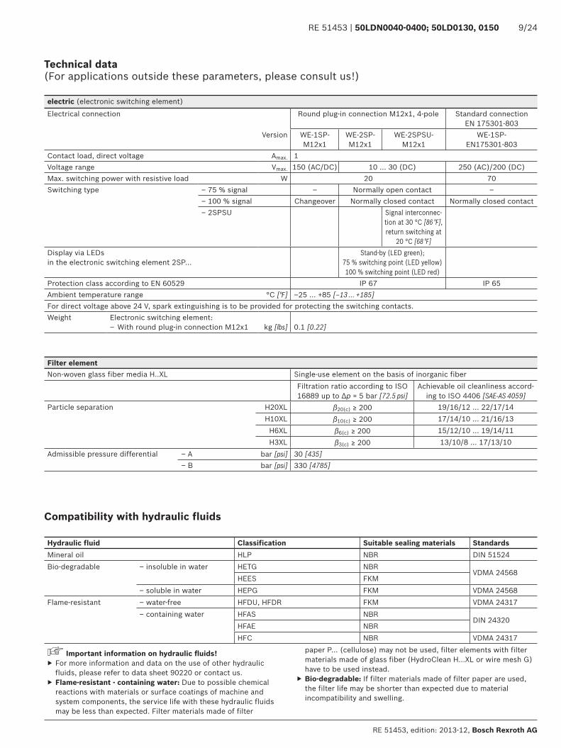
Technical data(For applications outside these parameters, please consult us!)
electric (electronic switching element)Electrical connection Round plug-in connection M12x1, 4-pole Standard connection
EN 175301-803Version WE-1SP-
M12x1WE-2SP-M12x1
WE-2SPSU-M12x1
WE-1SP-EN175301-803
Contact load, direct voltage Amax. 1Voltage range Vmax. 150 (AC/DC) 10 ... 30 (DC) 250 (AC)/200 (DC)Max. switching power with resistive load W 20 70Switching type – 75 % signal – Normally open contact –
– 100 % signal Changeover Normally closed contact Normally closed contact– 2SPSU Signal interconnec-
tion at 30 °C [86 °F], return switching at
20 °C [68 °F]Display via LEDsin the electronic switching element 2SP...
Stand-by (LED green); 75 % switching point (LED yellow) 100 % switching point (LED red)
Protection class according to EN 60529 IP 67 IP 65Ambient temperature range °C [°F] –25 … +85 [–13 … +185]For direct voltage above 24 V, spark extinguishing is to be provided for protecting the switching contacts.Weight Electronic switching element:
– With round plug-in connection M12x1 kg [lbs] 0.1 [0.22]
Filter elementNon-woven glass fiber media H..XL Single-use element on the basis of inorganic fiber
Filtration ratio according to ISO 16889 up to Δp = 5 bar [72.5 psi]
Achievable oil cleanliness accord-ing to ISO 4406 [SAE-AS 4059]
Particle separation H20XL β20(c) ≥ 200 19/16/12 … 22/17/14H10XL β10(c) ≥ 200 17/14/10 … 21/16/13
H6XL β6(c) ≥ 200 15/12/10 … 19/14/11H3XL β3(c) ≥ 200 13/10/8 … 17/13/10
Admissible pressure differential ‒ A bar [psi] 30 [435]‒ B bar [psi] 330 [4785]
Compatibility with hydraulic fluids
Hydraulic fluid Classification Suitable sealing materials StandardsMineral oil HLP NBR DIN 51524Bio-degradable – insoluble in water HETG NBR
VDMA 24568HEES FKM
– soluble in water HEPG FKM VDMA 24568Flame-resistant – water-free HFDU, HFDR FKM VDMA 24317
– containing water HFAS NBRDIN 24320
HFAE NBRHFC NBR VDMA 24317
Important information on hydraulic fl uids! ▶ For more information and data on the use of other hydraulic fluids, please refer to data sheet 90220 or contact us.
▶ Flame-resistant - containing water: Due to possible chemical reactions with materials or surface coatings of machine and system components, the service life with these hydraulic fluids may be less than expected. Filter materials made of filter
paper P... (cellulose) may not be used, filter elements with filter materials made of glass fiber (HydroClean H…XL or wire mesh G) have to be used instead.
▶ Bio-degradable: If filter materials made of filter paper are used, the filter life may be shorter than expected due to material incompatibility and swelling.
$",&99%:;+<&99%:;2,&99%:;
!(*+,-.-%!)$/,-.-%!$*),-.-%
!&%
%
,!&%
2
$
!)&%
!"&%
!$&%
!*&%
%, $,,
!$&%
", +,
!"&%!/%
<,
!$/% !"/%
", %,,
!&%
"
%
,!&%
!"&%
<, $%,
!*&%!$&%
$+,
!)&%
!
2
$
!/&%
!'&%
!(&%
!/&%
!*&%
!)&%
!"&%
!$&%
%, +,
!&%
%
,!&%
!(%
2, ",
!$"%!*%
!,
!$&%
2
$
!)&%
!"&%
!$&%
!*&%
$,
!$*%!0%!"%
%, $%,
!&%
"
%
,!&%
!"&%
+, <,
!*&%!$&%
$,,
!)&%
!
2
$
!/&%
!'&%
!(&%
!/&%
!*&%
!)&%
!"&%
!$&%
",
", %,,
!&%
"
%
,!&%
!"&%
<, $%,
!*&%!$&%
$+,
!)&%
!
2
$
!/&%
!'&%
!(&%
!/&%
!*&%
!)&%
!"&%
!$&%
", %,,
!&%
"
%
,!&%
!"&%
<, $%,
!*&%!$&%
$+,
!)&%
!
2
$
!/&%
!'&%
!(&%
!/&%
!*&%
!)&%
!"&%
!$&%
10/24 50LDN0040-0400; 50LD0130, 0150 | RE 51453
Bosch Rexroth AG, RE 51453, edition: 2013-12
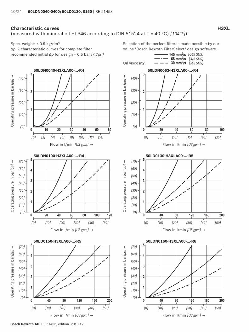
Characteristic curves H3XL(measured with mineral oil HLP46 according to DIN 51524 at T = 40 °C) [104 °F])
Selection of the perfect filter is made possible by our online "Bosch Rexroth FilterSelect" design software.
Oil viscosity:
Spec. weight: < 0.9 kg/dm3
Δp-Q characteristic curves for complete filterrecommended initial Δp for design = 0.5 bar [7.2 psi]
Ope
ratin
g pr
essu
re in
bar
[psi]
→
Flow in l/min [US gpm] →
50LDN0040-H3XLA00-...-R4
Ope
ratin
g pr
essu
re in
bar
[psi]
→
Flow in l/min [US gpm] →
50LDN0063-H3XLA00-...-R4
Ope
ratin
g pr
essu
re in
bar
[psi]
→
Flow in l/min [US gpm] →
50LDN0100-H3XLA00-...-R4
Ope
ratin
g pr
essu
re in
bar
[psi]
→
Flow in l/min [US gpm] →
50LD0130-H3XLA00-...-R5
Ope
ratin
g pr
essu
re in
bar
[psi]
→
Flow in l/min [US gpm] →
50LD0150-H3XLA00-...-R5
Ope
ratin
g pr
essu
re in
bar
[psi]
→
Flow in l/min [US gpm] →
50LDN0160-H3XLA00-...-R6
$",&99%:;+<&99%:;2,&99%:;
!(*+,-.-%!)$/,-.-%!$*),-.-%
!, 2,,
!&%
"
%
,!&%
!"&%
$!, %,,
!/&%!$&%
%!,
!)&%
!
2
$
!'&%
!(&%
!/&%
!*&%
!)&%
!"&%
!$&%
$,,
!'&%!*&% !(&%
<, ",,
!&%
"
%
,!&%
!*&%
$+, %",
!0&%!"&%
2%,
!(&%
!
2
$
!$&&%
!'&%
!(&%
!/&%
!*&%
!)&%
!"&%
!$&%
%, +,
!&%
%
,!&%
!(%
2, ",
!$"%!*%
!,
!$&%
2
$
!)&%
!"&%
!$&%
!*&%
$,
!$*%!0%!"% !&%
%
,!&%
2
$
!)&%
!"&%
!$&%
!*&%
%, $,,
!$&%
", +,
!"&%!/%
<,
!$/% !"/%
RE 51453 | 50LDN0040-0400; 50LD0130, 0150 11/24
RE 51453, edition: 2013-12, Bosch Rexroth AG
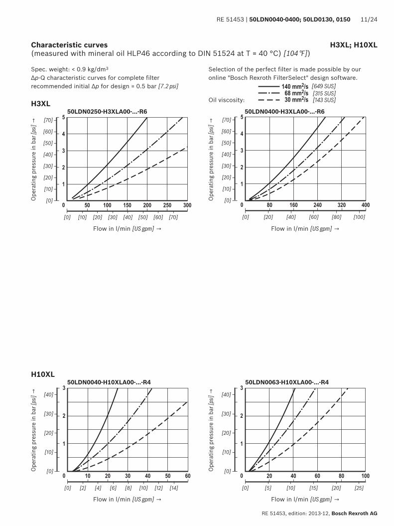
Selection of the perfect filter is made possible by our online "Bosch Rexroth FilterSelect" design software.
Oil viscosity:
Spec. weight: < 0.9 kg/dm3
Δp-Q characteristic curves for complete filterrecommended initial Δp for design = 0.5 bar [7.2 psi]
Ope
ratin
g pr
essu
re in
bar
[psi]
→
Flow in l/min [US gpm] →
50LDN0250-H3XLA00-...-R6
Ope
ratin
g pr
essu
re in
bar
[psi]
→
Flow in l/min [US gpm] →
50LDN0400-H3XLA00-...-R6
Characteristic curves H3XL; H10XL(measured with mineral oil HLP46 according to DIN 51524 at T = 40 °C) [104 °F])
H3XL
H10XL
Ope
ratin
g pr
essu
re in
bar
[psi]
→
Flow in l/min [US gpm] →
50LDN0040-H10XLA00-...-R4
Ope
ratin
g pr
essu
re in
bar
[psi]
→
Flow in l/min [US gpm] →
50LDN0063-H10XLA00-...-R4
", %,,
!&%
"
%
,!&%
!"&%
<, $%,
!*&%!$&%
$+,
!)&%
!
2
$
!/&%
!'&%
!(&%
!/&%
!*&%
!)&%
!"&%
!$&%
%, $%,
!&%
"
%
,!&%
!"&%
+, <,
!*&%!$&%
$,,
!)&%
!
2
$
!/&%
!'&%
!(&%
!/&%
!*&%
!)&%
!"&%
!$&%
",
$",&99%:;+<&99%:;2,&99%:;
!(*+,-.-%!)$/,-.-%!$*),-.-%
", %,,
!&%
"
%
,!&%
!"&%
<, $%,
!*&%!$&%
$+,
!)&%
!
2
$
!/&%
!'&%
!(&%
!/&%
!*&%
!)&%
!"&%
!$&%
", %,,
!&%
"
%
,!&%
!"&%
<, $%,
!*&%!$&%
$+,
!)&%
!
2
$
!/&%
!'&%
!(&%
!/&%
!*&%
!)&%
!"&%
!$&%
!, 2,,
!&%
"
%
,!&%
!"&%
$!, %,,
!/&%!$&%
%!,
!)&%
!
2
$
!'&%
!(&%
!/&%
!*&%
!)&%
!"&%
!$&%
$,,
!'&%!*&% !(&%
<, ",,
!&%
"
%
,!&%
!*&%
$+, %",
!0&%!"&%
2%,
!(&%
!
2
$
!$&&%
!'&%
!(&%
!/&%
!*&%
!)&%
!"&%
!$&%
12/24 50LDN0040-0400; 50LD0130, 0150 | RE 51453
Bosch Rexroth AG, RE 51453, edition: 2013-12
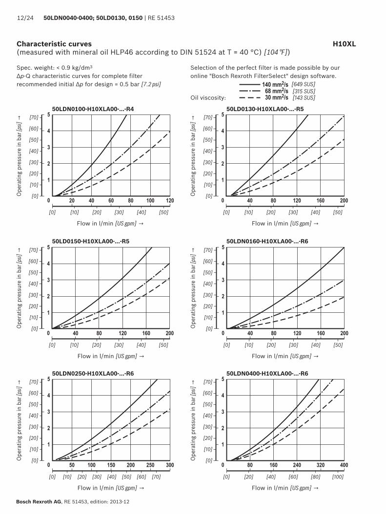
Characteristic curves H10XL(measured with mineral oil HLP46 according to DIN 51524 at T = 40 °C) [104 °F])
Selection of the perfect filter is made possible by our online "Bosch Rexroth FilterSelect" design software.
Oil viscosity:
Spec. weight: < 0.9 kg/dm3
Δp-Q characteristic curves for complete filterrecommended initial Δp for design = 0.5 bar [7.2 psi]
Ope
ratin
g pr
essu
re in
bar
[psi]
→
Flow in l/min [US gpm] →
50LDN0100-H10XLA00-...-R4
Ope
ratin
g pr
essu
re in
bar
[psi]
→
Flow in l/min [US gpm] →
50LD0130-H10XLA00-...-R5
Ope
ratin
g pr
essu
re in
bar
[psi]
→
Flow in l/min [US gpm] →
50LD0150-H10XLA00-...-R5
Ope
ratin
g pr
essu
re in
bar
[psi]
→
Flow in l/min [US gpm] →
50LDN0160-H10XLA00-...-R6
Ope
ratin
g pr
essu
re in
bar
[psi]
→
Flow in l/min [US gpm] →
50LDN0250-H10XLA00-...-R6
Ope
ratin
g pr
essu
re in
bar
[psi]
→
Flow in l/min [US gpm] →
50LDN0400-H10XLA00-...-R6
82
8+
8"
="&'&>%
8%72,$1
5?
7$7%
8$
=%
>$
7+
7! =2
@
8.
=2
7+8!
=!
7.
7"
=$
RE 51453 | 50LDN0040-0400; 50LD0130, 0150 13/24
RE 51453, edition: 2013-12, Bosch Rexroth AG
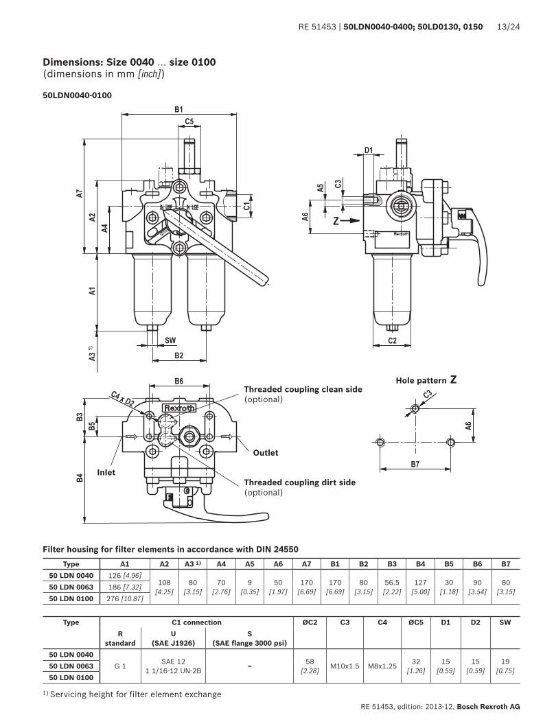
Dimensions: Size 0040 … size 0100(dimensions in mm [inch])
Inlet
Hole pattern Z
Outlet
Threaded coupling clean side (optional)
Threaded coupling dirt side (optional)
50LDN0040-0100
Filter housing for filter elements in accordance with DIN 24550
1) Servicing height for filter element exchange
Type A1 A2 A3 1) A4 A5 A6 A7 B1 B2 B3 B4 B5 B6 B750 LDN 0040 126 [4.96]
108 [4.25]
80[3.15]
70[2.76]
9 [0.35]
50[1.97]
170 [6.69]
170 [6.69]
80[3.15]
56.5[2.22]
127 [5.00]
30[1.18]
90 [3.54]
80[3.15]50 LDN 0063 186 [7.32]
50 LDN 0100 276 [10.87]
Type C1 connection ØC2 C3 C4 ØC5 D1 D2 SWR
standardU
(SAE J1926)S
(SAE fl ange 3000 psi)50 LDN 0040
G 1 SAE 121 1/16-12 UN-2B ‒ 58
[2.28] M10x1.5 M8x1.25 32 [1.26]
15 [0.59]
15 [0.59]
19 [0.75]50 LDN 0063
50 LDN 0100
82
8+
8"
8!
="&'&>%
8%
72&$1 5?
7$7%
8$
=%
>$
7+
7! =2
@
8.
=2
7+
8<
=!
7.
7"=$
14/24 50LDN0040-0400; 50LD0130, 0150 | RE 51453
Bosch Rexroth AG, RE 51453, edition: 2013-12
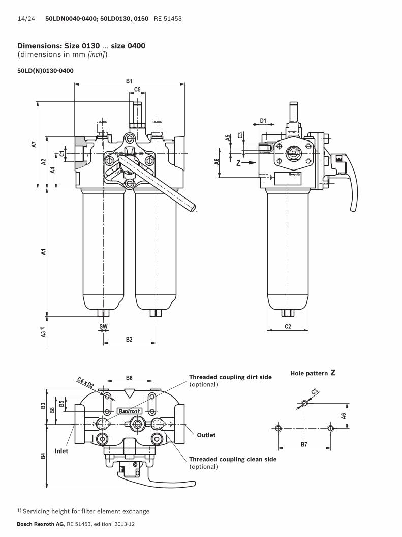
Dimensions: Size 0130 … size 0400(dimensions in mm [inch])
Inlet
Hole pattern Z
Outlet
Threaded coupling clean side (optional)
Threaded coupling dirt side (optional)
50LD(N)0130-0400
1) Servicing height for filter element exchange
RE 51453 | 50LDN0040-0400; 50LD0130, 0150 15/24
RE 51453, edition: 2013-12, Bosch Rexroth AG
Filter housing for filter elements according to DIN 24550 and according to Rexroth standard
Dimensions: Size 0130 … size 0400(dimensions in mm [inch])
Type A1 A2 A3 1) A4 A5 A6 A7 B1 B2 B3 B4 B5 B6
50LD0130 213[8.39] 99
[3.90]
140[5.51]
69[2.72]
12[0.47]
50[1.97]
173[6.81]
220[8.66]
105[4.13]
70[2.76]
128[5.04]
30[1.18]
90 [3.54]
50LD0150 257[10.12]
50LDN0160 184[7.24]
115[4.53]
80[3.15]
25[0.98]
55[2.17]
184[7.24]
270[10.63]
134[5.28]
103[4.06]
152[5.98]
130[5.12]50LDN0250 274
[10.79]
50LDN0400 425[16.73]
Type B7 B8 C1 connection ØC2 C3 C4 ØC5 D1 D2 SWR
standardU
(SAE J1926)S
(SAE fl ange 3000 psi)
50LD0130 105[4.13]
65[2.56]
G 1 1/4 SAE 121 5/16-12 UN-2B SAE 1 1/4" 82
[3.23] M12 M8
32 [1.26]
18[0.71]
12[0.47]
22[0.87]50LD0150
50LDN0160134
[5.28] G 1 1/2 SAE 201 5/8-12 UN-2B" SAE 1 1/2" 98
[3.86] M16 M10 22[0.87]
15 [0.59]
27[1.06]50LDN0250
50LDN0400
A$
""*%
,!$#'
*%
#%,'$*!
%+*!,!$#&*%
"<*.,!$#+"%
..*!,!)#&/%
..*!
,!)#&
/%2!*!
,!$#*
&%%!
,!&#+
0%
BC'DEFG
.
$
2
+
!
A%
#%,'$*!A$
""*%
,!$#
'*%
#%,'$*!
%+*!,!$#&*%
".*!,!$#0'%
+,,!"#)(%
..*!
,!)#&
/%2!*!
,!$#*
&%%!
,!&#+
0%$,,-
.!-
BC'DEFG
.
$
%
"
+
!
A%
#$%'$
16/24 50LDN0040-0400; 50LD0130, 0150 | RE 51453
Bosch Rexroth AG, RE 51453, edition: 2013-12
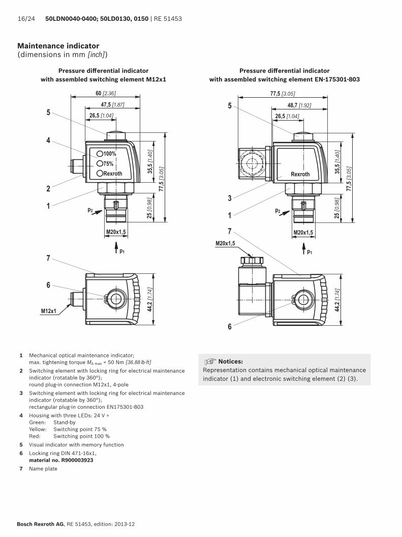
Maintenance indicator(dimensions in mm [inch])
Pressure diff erential indicator with assembled switching element M12x1
Pressure diff erential indicator with assembled switching element EN-175301-803
1 Mechanical optical maintenance indicator; max. tightening torque MA max = 50 Nm [36.88 lb-ft]
2 Switching element with locking ring for electrical maintenance indicator (rotatable by 360°);round plug-in connection M12x1, 4-pole
3 Switching element with locking ring for electrical maintenance indicator (rotatable by 360°);rectangular plug-in connection EN175301-803
4 Housing with three LEDs: 24 V =Green: Stand-byYellow: Switching point 75 %Red: Switching point 100 %
5 Visual indicator with memory function6 Locking ring DIN 471-16x1,
material no. R9000039237 Name plate
Notices: Representation contains mechanical optical maintenance indicator (1) and electronic switching element (2) (3).
RE 51453 | 50LDN0040-0400; 50LD0130, 0150 17/24
RE 51453, edition: 2013-12, Bosch Rexroth AG
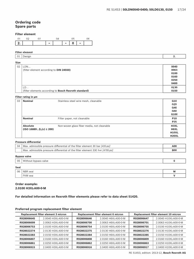
Preferred program replacement fi lter element
Filter element01 Design 2.
Size02 LDN...
(fi lter element according to DIN 24550)004000630100016002500400
LD... (fi lter elements according to Bosch Rexroth standard)
01300150
Filter rating in µm03 Nominal Stainless steel wire mesh, cleanable G10
G25G40G60G100
Nominal Filter paper, not cleanable P10P25
Absolute (ISO 16889 ; βx(c) ≥ 200)
Non-woven glass fi ber media, not cleanable H3XLH6XLH10XLH20XL
Pressure diff erential04 Max. admissible pressure diff erential of the fi lter element 30 bar [435 psi] A00
Max. admissible pressure diff erential of the fi lter element 330 bar [4785 psi] B00
Bypass valve05 Without bypass valve 0
Seal06 NBR seal M
FKM seal V
01 02 03 04 05 06
2. – – 0 –
Order example:2.0100 H3XL-A00-0-M
For detailed information on Rexroth fi lter elements please refer to data sheet 51420.
Ordering code Spare parts
Filter element
Replacement fi lter element 3 micron Replacement fi lter element 6 micron Replacement fi lter element 10 micronR928006645 2.0040 H3XL-A00-0-M R928006646 2.0040 H6XL-A00-0-M R928006647 2.0040 H10XL-A00-0-MR928006699 2.0063 H3XL-A00-0-M R928006700 2.0063 H6XL-A00-0-M R928006701 2.0063 H10XL-A00-0-MR928006753 2.0100 H3XL-A00-0-M R928006754 2.0100 H6XL-A00-0-M R928006755 2.0100 H10XL-A00-0-MR928022274 2.0130 H3XL-A00-0-M R928022275 2.0130 H6XL-A00-0-M R928022276 2.0130 H10XL-A00-0-MR928022283 2.0150 H3XL-A00-0-M R928022284 2.0150 H6XL-A00-0-M R928022285 2.0150 H10XL-A00-0-MR928006807 2.0160 H3XL-A00-0-M R928006808 2.0160 H6XL-A00-0-M R928006809 2.0160 H10XL-A00-0-MR928006861 2.0250 H3XL-A00-0-M R928006862 2.0250 H6XL-A00-0-M R928006863 2.0250 H10XL-A00-0-MR928006915 2.0400 H3XL-A00-0-M R928006916 2.0400 H6XL-A00-0-M R928006917 2.0400 H10XL-A00-0-M
18/24 50LDN0040-0400; 50LD0130, 0150 | RE 51453
Bosch Rexroth AG, RE 51453, edition: 2013-12
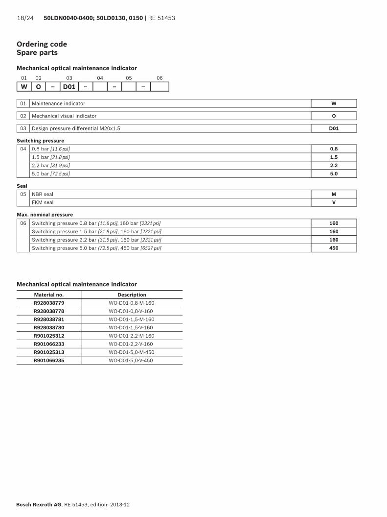
Ordering code Spare parts
01 02 03 04 05 06
W O – D01 – – –
Mechanical optical maintenance indicator
Mechanical optical maintenance indicator
01 Maintenance indicator W
02 Mechanical visual indicator O
03 Design pressure diff erential M20x1.5 D01
Switching pressure04 0.8 bar [11.6 psi] 0.8
1.5 bar [21.8 psi] 1.52.2 bar [31.9 psi] 2.25.0 bar [72.5 psi] 5.0
Seal05 NBR seal M
FKM seal V
Max. nominal pressure06 Switching pressure 0.8 bar [11.6 psi], 160 bar [2321 psi] 160
Switching pressure 1.5 bar [21.8 psi], 160 bar [2321 psi] 160Switching pressure 2.2 bar [31.9 psi], 160 bar [2321 psi] 160Switching pressure 5.0 bar [72.5 psi], 450 bar [6527 psi] 450
Material no. DescriptionR928038779 WO-D01-0,8-M-160R928038778 WO-D01-0,8-V-160R928038781 WO-D01-1,5-M-160R928038780 WO-D01-1,5-V-160R901025312 WO-D01-2,2-M-160R901066233 WO-D01-2,2-V-160R901025313 WO-D01-5,0-M-450R901066235 WO-D01-5,0-V-450
RE 51453 | 50LDN0040-0400; 50LD0130, 0150 19/24
RE 51453, edition: 2013-12, Bosch Rexroth AG
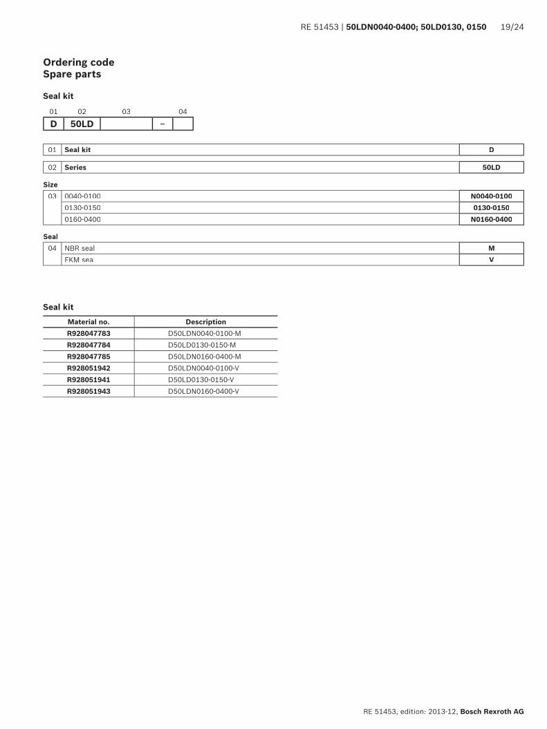
01 Seal kit D
02 Series 50LD
Size03 0040-0100 N0040-0100
0130-0150 0130-01500160-0400 N0160-0400
Seal04 NBR seal M
FKM seal V
01 02 03 04
D 50LD –
Seal kit
Seal kit
Ordering code Spare parts
Material no. DescriptionR928047783 D50LDN0040-0100-MR928047784 D50LD0130-0150-MR928047785 D50LDN0160-0400-MR928051942 D50LDN0040-0100-VR928051941 D50LD0130-0150-VR928051943 D50LDN0160-0400-V
20/24 50LDN0040-0400; 50LD0130, 0150 | RE 51453
Bosch Rexroth AG, RE 51453, edition: 2013-12
Assembly, commissioning, maintenance
AssemblyThe max. operating pressure of the system must not exceed the max. admissible operating pressure of the filter (see name plate).During assembly of the filter (see also chapter "Tightening torques"), the flow direction (direction arrows) and the required servicing height of the filter element (see chapter "Dimensions") are to be considered.
Proper function is only guaranteed in the installation with the filter bowl vertically downwards. The maintenance indi-cator must be arranged so it is easily viewed in operation.Remove the plastic plugs in the filter inlet and outlet.
Ensure that the system is assembled without tension stress.
The optional electronic maintenance indicator is connected via the electronic switching element with 1 or 2 switching points, which is attached to the mechanical optical mainte-nance indicator and held by means of the locking ring.
CommissioningBring the switching lever into central position in order to fill both filter sides.Start the system.Bleed filter by opening the bleed screws or bleed valves, close when operating liquid begins to escape..Switch the filter into the operating position; to do so, switch the switching lever to one of the two end positions.The switch-over lever is on the filter side that is out of order.
Maintenance ▶ If at operating temperature, the red indicator pin reaches
out of the mechanical optical maintenance indicator and/or if the switching process in the electronic switching element is triggered, the filter element is contaminated and needs to be replaced or cleaned respectively.
▶ The material number of the corresponding replacement filter element is indicated on the name plate of the complete filter. It must correspond to the material number on the filter element.
▶ The switch-over lever is on the filter side that is out of order. Observe the switching symbol on the switching lever and/or the switch-over.
▶ For pressure equalization and unlocking, pull the switch-over lever and switch to the opposite end position.
▶ Open the bleed screw or bleed valve at the decommis-sioned filter side in order to reduce the pressure.
▶ Via the drain screw (from size 0160 and larger), the oil on the dirt side can be drained.
▶ Unscrew the filter bowl ‒ see figure assembly aid. ▶ Remove the filter element from the spigot by rotating
it slightly. ▶ Clean the filter components, if necessary. ▶ Check the seals at the filter bowl for damage and
replace them, if necessary.For suitable seal kits refer to chapter "Spare parts".
▶ Filter elements made of wire mesh can be cleaned. The efficiency of the cleaning process depends on the type of dirt and the amount of the pressure differential before the filter element exchange. If the pressure differential after the filter element exchange exceeds 150 % of the value of a brand-new filter element, the filter element made of wire mesh (G…) also needs to be replaced. For detailed cleaning instructions refer to data sheet 51420.
▶ Install the new or cleaned filter element on the spigot again by slightly rotating it.
▶ The filter is to be assembled in reverse order. ▶ The torque specifications ("Tightening torques" chap-
ter) are to be observed. ▶ To fill the maintained filter side, pull the switch-
over lever. ▶ The filter is bled via the bled screw or the bleed valve
which is still open. ▶ After fluid escapes, close the bleed screw or the bleed
valve again. ▶ Make sure that the switch-over lever is engaged.
HI&J5K HI&J5K HI&J5K HI&J5KHI&J5K HI&J5K HI&J5K HI&J5K
RE 51453 | 50LDN0040-0400; 50LD0130, 0150 21/24
RE 51453, edition: 2013-12, Bosch Rexroth AG
Assembly, commissioning, maintenance
CorrectCorrect
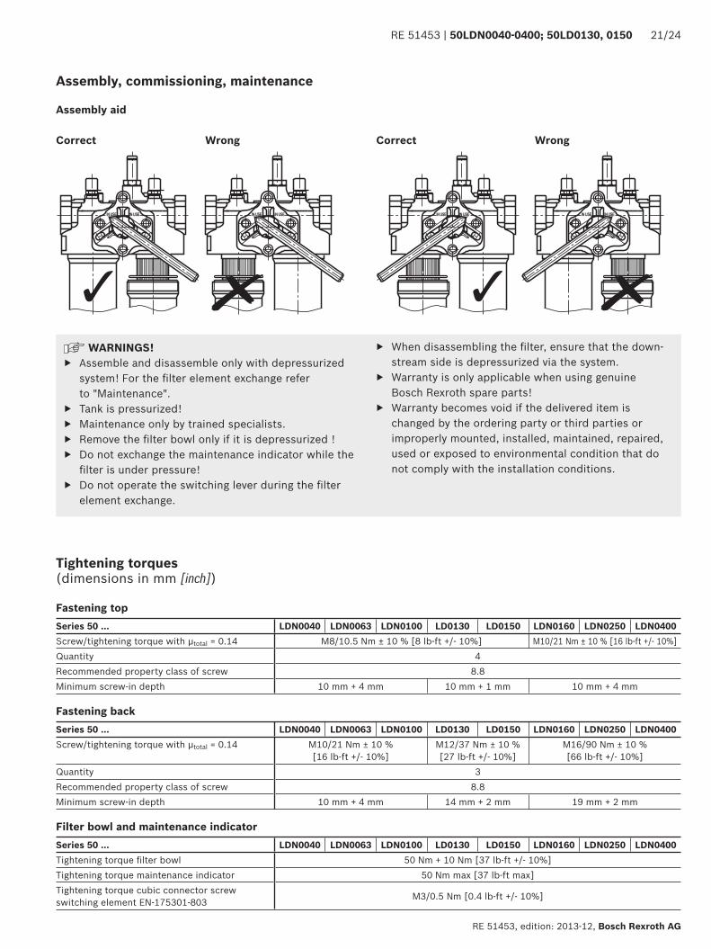
Assembly aid
WrongWrong
WARNINGS! ▶ Assemble and disassemble only with depressurized
system! For the fi lter element exchange refer to "Maintenance".
▶ Tank is pressurized! ▶ Maintenance only by trained specialists. ▶ Remove the fi lter bowl only if it is depressurized ! ▶ Do not exchange the maintenance indicator while the
fi lter is under pressure! ▶ Do not operate the switching lever during the fi lter
element exchange.
▶ When disassembling the fi lter, ensure that the down-stream side is depressurized via the system.
▶ Warranty is only applicable when using genuine Bosch Rexroth spare parts!
▶ Warranty becomes void if the delivered item is changed by the ordering party or third parties or improperly mounted, installed, maintained, repaired, used or exposed to environmental condition that do not comply with the installation conditions.
Tightening torques(dimensions in mm [inch])
Fastening topSeries 50 ... LDN0040 LDN0063 LDN0100 LD0130 LD0150 LDN0160 LDN0250 LDN0400Screw/tightening torque with μtotal = 0.14 M8/10.5 Nm ± 10 % [8 lb-ft +/- 10%] M10/21 Nm ± 10 % [16 lb-ft +/- 10%]Quantity 4Recommended property class of screw 8.8Minimum screw-in depth 10 mm + 4 mm 10 mm + 1 mm 10 mm + 4 mm
Fastening backSeries 50 ... LDN0040 LDN0063 LDN0100 LD0130 LD0150 LDN0160 LDN0250 LDN0400Screw/tightening torque with μtotal = 0.14 M10/21 Nm ± 10 %
[16 lb-ft +/- 10%]M12/37 Nm ± 10 %[27 lb-ft +/- 10%]
M16/90 Nm ± 10 % [66 lb-ft +/- 10%]
Quantity 3Recommended property class of screw 8.8Minimum screw-in depth 10 mm + 4 mm 14 mm + 2 mm 19 mm + 2 mm
Filter bowl and maintenance indicatorSeries 50 ... LDN0040 LDN0063 LDN0100 LD0130 LD0150 LDN0160 LDN0250 LDN0400Tightening torque fi lter bowl 50 Nm + 10 Nm [37 lb-ft +/- 10%]Tightening torque maintenance indicator 50 Nm max [37 lb-ft max]Tightening torque cubic connector screw switching element EN-175301-803 M3/0.5 Nm [0.4 lb-ft +/- 10%]
22/24 50LDN0040-0400; 50LD0130, 0150 | RE 51453
Bosch Rexroth AG, RE 51453, edition: 2013-12
Directives and standardization
Classification according to the Pressure Equip-ment DirectiveThe duplex filters for hydraulic applications according to 51453 are pressure holding equipment according to arti-cle 1, section 2.1.4 of the Pressure Equipment Direc-tive 97/23/EC (PED). However, based on the exception in
article 1, section 3.6 of the PED, hydraulic filters are exempt from the PED if they are not classified higher than category I (guideline 1/19).They do not receive a CE mark.
Zone suitabilityGas 1 2Dust 21 22
Use in explosive areas according to directive 94/9/EC (ATEX)The duplex filters according to 51453 are not equipment or components in the sense of directive 94/9/EC and are not provided with a CE mark. It has been proven with the ignition risk analysis that these inline filters do not have own ignition sources acc. to DIN EN 13463-1:2009.
According to DIN EN 60079-11:2012, the electronic mainte-nance indicators WE-1SP-M12x1 and WE-1SP-EN175301-803 are simple, electronic operating equipment not having an own voltage source. This simple, electronic operating
equipment may - according to DIN EN 60079-14:2008 - in intrinsically safe electric circuits (Ex ib) be used in systems without marking and certification.The duplex filters and the electronic maintenance indicators described here can be used for the following explosive areas:
Complete filter with mech./opt. maintenance indicatorUse /assignment Gas 2G Dust 2D
Assignment Ex II 2G c IIB TX Ex II 2D c IIB TXConductivity of the medium pS/m min 300
Dust accumulation max ‒ 0.5 mm
Electronic switching element in the intrinsically safe electric circuitUse /assignment Gas 2G Dust 2D
Assignment Ex II 2G Ex ib IIB T4 Gb Ex II 2D Ex ib IIIC T100 °C DbAdm. intrinsically safe electric circuits Ex ib IIC, Ex ic IIC Ex ib IIIC
Technical data Values only for intrinsically safe electric circuitSwitching voltage Ui max 150 V AC/DCSwitching current Ii max 1.0 ASwitching power Pi max 1.3 W T4 Tmax 40 °C 750 mW Tmax 40 °C
max 1.0 W T4 Tmax 80 °C 550 mW Tmax 100 °CSurface temperature 1) max ‒ 100 °C
Inner capacity Ci NeglectableInner inductivity Li Neglectable
Dust accumulation max ‒ 0.5 mm1) The temperature depends on the temperature of the medium in the filter and must not exceed the value specified here.
RE 51453 | 50LDN0040-0400; 50LD0130, 0150 23/24
RE 51453, edition: 2013-12, Bosch Rexroth AG
Directives and standardization
!,$
",$
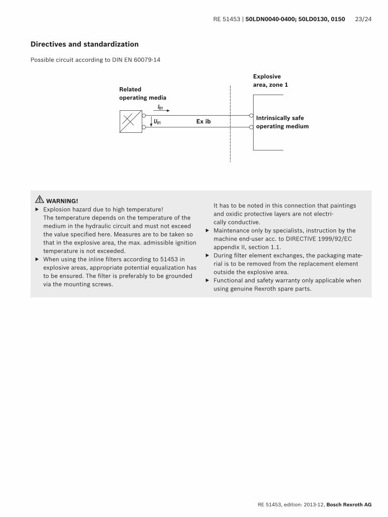
Possible circuit according to DIN EN 60079-14
Related operating media
Explosive area, zone 1
Intrinsically safe operating medium
Ex ib
WARNING! ▶ Explosion hazard due to high temperature!
The temperature depends on the temperature of the medium in the hydraulic circuit and must not exceed the value specifi ed here. Measures are to be taken so that in the explosive area, the max. admissible ignition temperature is not exceeded.
▶ When using the inline fi lters according to 51453 in explosive areas, appropriate potential equalization has to be ensured. The fi lter is preferably to be grounded via the mounting screws.
It has to be noted in this connection that paintings and oxidic protective layers are not electri-cally conductive.
▶ Maintenance only by specialists, instruction by the machine end-user acc. to DIRECTIVE 1999/92/EC appendix II, section 1.1.
▶ During fi lter element exchanges, the packaging mate-rial is to be removed from the replacement element outside the explosive area.
▶ Functional and safety warranty only applicable when using genuine Rexroth spare parts.
Bosch Rexroth AG, RE 51453, edition: 2013-12
24/24 50LDN0040-0400; 50LD0130, 0150 | RE 51453
Bosch Rexroth AGKetsch plantHardtwaldstr. 4368775 Ketsch, GermanyPhone +49 (0) 62 02 / 603-0fi [email protected]
© This document, as well as the data, specifi cations and other information set forth in it, are the exclusive property of Bosch Rexroth AG. It may not be reproduced or given to third parties without its consent.The data specifi ed above only serve to describe the product. No statements concerning a certain condition or suitability for a certain application can be derived from our information. The information given does not release the user from the obligation of own judgment and verifi cation. It must be remembered that our products are subject to a natural process of wear and aging.
Notes