dupont fire extinguishants
TRANSCRIPT

DuPont Fire Extinguishants ComParison TEsTing oF FE-25™ anD auTomaTiC
sPrinklErs in a simulaTED DaTa ProCEssing/
TElECommuniCaTions FaCiliTy
W H I T E P A P E R
Mark L. Robin, PhDDuPont Fluoroproducts
INTRODUCTION
Data processing and telecommunication facilities are commonly protected against fire with a gaseous clean agent system, an automatic sprinkler system, or with both a clean agent system and an automatic sprinkler system. The degree of protection provided by these systems is different, as is the cost incurred in employing these systems. The test comparison reported here was performed in order to illustrate the differences in the protection provided by automatic sprinkler systems and the gaseous clean agent FE-25TM (HFC-125). In addition, the production of combustion products was monitored in order to assess the relative environmental and health impacts associated with the suppression of a typical fire with gaseous clean agent and sprinkler systems. Tests were conducted in a simulated telecommunications/data processing facility and examined the performance of the suppression systems on a fire involving plastic materials located inside a metal electronic equipment cabinet.
SPRINKLERS
The main objectives of clean agent and automatic sprinkler systems are quite different. The main objective of an automatic sprinkler system, whether pre-action or wet pipe, is to contain the fire to the room of origin and to manage the temperatures at the ceiling to prevent structural damage and/or collapse. In other words, the main objective of an automatic sprinkler system is not to extinguish a fire, but to control a fire. Automatic sprinkler systems are activated when the temperature at the liquid-filled glass bulb or fusible link of the sprinkler assembly exceeds the temperature rating of the sprinkler head. Sprinkler heads with the lowest temperature ratings are classified as “ordinary” sprinkler heads, and do not activate until a temperature of 135 oF (57 oC) is attained at the glass bulb or fusible link. The transfer of heat to the glass bulb or fusible link is not instantaneous, and as a result the sprinkler will not activate until the temperature at the sprinkler head reaches a value in excess of the temperature rating of the head. Table 1 shows the results of the calculation of the

response times of typical standard and fast response sprinkler heads for a slow growth fire located 7.8 ft (2.4 m) radially from the fire source, assuming a 10 ft (3.1 m) ceiling.
As shown in Table 1, activation does not occur until the temperature of the ceiling jet at the sprinkler head reaches a temperature exceeding the rating of the head. A fairly large fire, with a heat release rate in the range of several hundreds of kilowatts, is typically required to produce ceiling temperatures sufficient to activate a sprinkler system. Note in this example that sprinkler activation does not occur until the heat release rate is in excess of 200 kW.
Table 1: Sprinkler Response for a Slow Growth Fire
Sprinkler head
Temperaturerating
Radialdistance to
detector
Ceiling JetTemperature
at head
Heat ReleaseRate at SprinklerActivation (kW)
Standard 135 oF 7.8 ft 167 oF 278Fast Response 135 oF 7.8 ft 153 oF 220
Source: FPETool calculation.
CLEAN AGENT SYSTEMS
The main objective of a gaseous clean agent system is to extinguish the fire quickly, limiting the fire damage to the object(s) involved in the origin of the fire. A smoke detection system is utilized to actuate the gaseous agent system while the fire is much smaller than that required to activate a sprinkler system. Air aspiration type detection systems are capable of detecting fires as small as 0.1 kW in size, and standard ionization and photoelectric smoke detection systems are capable of detecting fires in their incipient stages. As a result, fires are small at the time of activation of gaseous clean agent systems and ceiling jet temperatures are low, often only a few degrees higher than ambient temperatures.
Figure 1 illustrates graphically the different nature of a typical gaseous clean agent system (FE-25TM) and an automatic sprinkler system.
Figure 1: Comparison of Automatic Sprinkler and Clean Agent Systems
Time
HeatRelease
Rate
Sprinkler activation
FE-25 system activation
Detection
FIRE CONTROL
FIRE EXTINGUISHMENT
CLEAN AGENT SYSTEM
SPRINKLER SYSTEM
Smoke Aspiration

Simulated Telecommunications/Data Processing Facility
A test room was designed, constructed and outfitted to simulate a typical telecommunications or data processing facility. The simulated facility and the test arrangement are shown in Figures 2 and 3.
The comparison tests were performed in a 20 ft x 30 ft x 10 ft enclosure constructed with fiberglass reinforced plastic (polyester resin) wall and ceiling panels and equipped with a suspended ceiling located 2 ft below the enclosure ceiling. Access to the room was accomplished via two standard (2.9 ft x 6.6 ft) doors, one at the north end of the west wall and the other at the south end of the west wall. The enclosure was equipped with four polycarbonate observation windows, two located on the west wall and two located on the south wall. An 18.5 in x 26 in opening was provided in the east wall to accommodate the installation of an air conditioning unit located 67 inches off the floor.
In addition to the equipment cabinet containing the fuel array (Rack 1 in Figure 3), a large data processing equipment cabinet (Rack 2 in Figure 3) was also arranged in the test enclosure. A desk, two file cabinets and a computer with monitor were also arranged in this area.
Figure 2: Simulated Telecommunication/Data Processing Facility

A/C penetration18-1/2”h X 26” w67” off floor to bottom
Electrical box
windowwindow
door
window
window
door
desk
Rack 2
30 ft
20 ft
Figure 3 – Enclosure Schematic
file
Rack 1
file
Test Fire
The test fire set-up is shown schematically in Figure 4 and consisted of eight sheets (8 in x 16 in x 0.375 in) of Acrylonitrile-Butadiene-Styrene (ABS) polymer, arranged vertically in two rows of four sheets each. The four sheets in each row are arranged with 1.27 cm (0.5 in.) gaps between the outer sheets and a larger center gap of 1.25 in (3.2 cm). The array was placed inside a cabinet with metal mesh doors with the sheets parallel to the solid metal walls of the cabinet. The ABS array was ignited by 3 ml of n-heptane in a 2 in (5 cm) square pan located 0.5 inches (1.27 cm) below the array. This fire set-up is similar to that adopted by Underwriters Laboratories, Inc in their standard on Halocarbon Clean Agent Extinguishing System Units, UL 2166 [1].
The heat release rate for the test fire was determined as part of a previous study [2] and is shown in Figure 5.
Smoke Detection System
The detection/alarm system was installed in accordance with NFPA 72, National Fire Alarm Code [4]. The smoke detection system consisted of two FirstAlert photoelectric smoke detectors; the alarm threshold for these detectors was 2.0 % obscuration per foot. A detector spacing of 10 ft (3.0 m) was employed. Factory Mutual Loss Prevention Data Sheet 5-32 on

Figure 4: Fuel Array Schematic
1 ¼” Eight Sheets of ½” ½” 8 x 16 x 3/8 in
ABS
76 ½” 16”
½” 16” ½” 1” 7” 21 ¾” 38”
2 in pan with 3 ml n-Heptane
Figure 5: Heat Release Rate for ABS Plastic Fuel Array
0
50
100
150
200
250
300
350
400
450
500
0 100 200 300 400 500
Time, seconds
Hea
t Rel
ease
, kW

Electronic Data Processing Systems [5] recommends a maximum detector spacing of 15.8 ft (4.8 m), corresponding to an area coverage of 250 ft2 (23 m2). NFPA 72 allows a detector spacing of up to 30 ft (9.2 m), corresponding to an area coverage of 900 ft2 (83.6 m2). Figure 6 shows the smoke detector locations, in addition to the gaseous clean agent nozzle and sprinkler heard locations.
10 ft
A/C penetration18-1/2”h X 26” w67” off floor to bottom
Electrical box
windowwindow
door
window
window
door
Figure 6 – Smoke Detector and Sprinkler Systems
10 ft
Sprinkler head
Detector
FE-25TM System
The FE-25TM system was designed utilizing the Fike Ecaro-25 Flow Calculation Software, version 3.30.0000 to discharge 169 lb of FE-25TM into the main area of the enclosure in 10 seconds to result in a 9.0 % by volume concentration inside the enclosure. The agent was discharged from an 87 L Fike cylinder part number 70-154, through a flex hose, part number 6540, and a short piping system constructed from 5 cm (2 in) NPT schedule 40 threaded steel pipe terminating in a Fike aluminum nozzle with a total orifice diameter of 0.7187 inches located in the center of the room.
The FE-25TM system incorporated a 30 second delay from detection to cylinder actuation. This delay is the maximum delay time under the recommendations of FM Global Property loss prevention sheet 5-14 on Telecommunications Facilities [6]. The FE-25TM system design employed also meets the requirements of NFPA 2001 Standard on Clean Agent Extinguishing Systems [7].
Automatic Sprinkler System
The automatic sprinkler system was designed in accordance with NFPA 13 [8]. The design was based upon an Ordinary Hazard Class I classification for this room. Data processing spaces can be classified as Light Hazards if the space can be kept clear of combustible materials outside of the data processing equipment cabinets. A sprinkler head spacing of 10 ft was employed as shown in Figure 6. This provides an area coverage of 100 ft2 for each head, in compliance with NFPA 13 maximum spacing requirements for ordinary hazards of 15 ft (4.6 m) and coverage area of 130 ft2 (12.1 m2) [8]. In order to simplify the experimental procedure, only the two sprinkler heads closest to the fuel cabinet containing the fuel array were connected to the water supply, as it was anticipated that at the worst case only these two sprinkler heads would be activated.
The sprinkler heads utilized were Swift Fire Protection, Inc. SPC135 pendent glass bulb sprinklers with a temperature rating of 68 oC (135 oF) and a K value of 5.6 gpm/psi0.5 (8.073 lpm/kPa0.5).
The application density for ordinary hazard class I rooms less than 139.4 m2 (1500 ft2) is 6.11 lpm/m2 (0.15 gpm/ft2) [8]. The total floor area of the test enclosure was 600 ft2, and hence a total flow of 90 gpm is required to provide an application density of 0.15 gpm/ft2, and the required flowrate of water through each of the six nozzles would be 15 gpm. The required pressure at the sprinkler head is calculated from the expression
Q = KP1/2
where Q is the flowrate in gpm, K is the K-factor of the sprinkler head and P is the water pressure in psi. The required pressure is thus calculated to be 7 psig.
The sprinkler piping system was designed based on the above requirements with the aid of the software program Simple Hydraulic Calculator, version 1.4.6.
Pre-action systems sprinkler systems are sometimes employed to protect data processing and telecommunication facilities. These differ from standard sprinkler systems in that the piping upstream of the sprinkler heads (closed) is dry. A quick opening valve usually actuated by a separate smoke detection system holds the water that eventually flows through the sprinkler heads back. Once the valve has been actuated, there is no difference in performance between the pre-action and standard sprinkler systems.
NFPA 13 would require that the water supply be adequate to supply all of the sprinklers within the design area for a minimum duration of 60 minutes [8]. In the case of this system the full flow requirement would be 5,400 gallons of water.

Enclosure Instrumentation
The test enclosure was instrumented to monitor temperatures, pressures, species concentrations and the operation of the FE-25TM and sprinkler systems. A vertical thermocouple tree was installed in the enclosure at a location approximately 6 ft from the fuel array cabinet, and was equipped with Type K thermocouple located at 2, 4, 6, and 8 ft from the enclosure floor. Additional thermocouples were located at the two sprinkler heads closest to the fire array cabinet, at the bottom and top of the fuel array, on top of the fuel array cabinet and at the ceiling directly above the fuel array cabinet.
An Omega Engineering PX653-05BD5V pressure transducer was utilized to monitor the pressure in the test chamber; a type K thermocouple and an Omega Engineering PX603-1KG5V pressure transducer were utilized to monitor the nozzle pressure of the FE-25TM discharge.
Gaseous combustion products were measured in situ via Fourier Transform Infrared Spectroscopy (FTIR) and via the analysis of grab samples obtained during the suppression tests. Two FTIRs were employed for this test series; the primary instrument was equipped with a 10-meter multi-pass gas cell, while the second instrument (which was used primarily to measure high levels of FE-25TM, CO, CO2, COF2, HCl, and HF) was equipped with a single-pass 15-centimeter gas cell. During the tests an enclosure air sample was continuously drawn from inside the room. The sample was drawn through the long path (10-meter) FTIR gas cell via Teflon tubing at a rate of approximately 12 liters per minute (lpm) using a diaphragm pump. The sample exited the first FTIR and was then directed to the second short path (15-centimeter) FTIR for further analysis. The cell pressure was monitored via a pressure transducer and the cell temperature was controlled at 121oC. Data acquisition began approximately 1 minute prior to the fire being ignited and continued for several minutes after each test.
AutoQuantTM software (Midac Corp.) was used for spectral acquisition and processing. AutoQuantTM uses a classic least squares (CLS) algorithm that generates quantitative results based on the comparison of reference spectra to the sample spectrum. Prior to testing reference spectra for each analyte were prepared from certified gas standards on each spectrometer used during testing.
Oxygen measurements were made using an Oxigraf analyzer. The analyzer uses a 0-1 volt analog output that is equivalent to the concentration of the gas being measured. The analog signals were recorded using a computer system equipped with a National Instruments 16-bit data acquisition card. A LabView program was used to calibrate and record the data from each of the data acquisition (DAQ) channels used. The data was collected and saved as a text file to the computer hard drive and a spreadsheet program was then used to analyze and plot the data.
A Thermocam SC-1000 infrared (IR) camera was employed to monitor the progress of the test fires. The camera was mounted inside the test enclosure and aimed at the fuel array within the cabinet.
Grab vapor samples were collected in evacuated stainless steel cylinders during the tests from a location directly behind the fuel array cabinet. These samples were analyzed by DuPont via FTIR and gas chromatography-mass spectroscopy (GC-MS) techniques. Solid samples collected from the floor following the sprinkler test were analyzed by FTIR and Raman spectroscopies, and aqueous samples collected from the floor following the sprinkler tests were examined via ion chromatography.

Test Procedure
Data acquisition was commenced 30 seconds prior to the ignition of the n-heptane pan below the ABS plastic array. During the FE-25TM tests, the system was actuated 30 seconds after the smoke detector went into alarm. The enclosure remained sealed with the doors and vents closed and the exhaust blower shut down until 10 minutes after system actuation. In the case of the sprinkler test, system activation was automatic. The fire was not extinguished by the water sprinkler system and as a result was extinguished with a portable dry powder extinguisher.
RESULTS AND DISCUSSION
System Performance: FE-25TM
Results from the suppression of the test fire with FE-25TM are summarized in Table 2.
Table 2: FE-25™ Suppression Results
Run
MaximumNozzle
Pressure(psig)
Ext timefrom EOD
(s)
MaximumRoom Pressure
(iwc)
MaximumCeiling Temp
(oF)
1 80 8- 0.21+ 0.35 75
2 82 2- 0.28+ 0.42 72
3 75 2- 0.35+ 0.35 72
EOD = end of discharge
The FE-25TM suppression system performed as intended, providing rapid detection and extinguishment of the fire. Damage to the enclosure was limited to the dislodging of several ceiling tiles. Damage to the enclosure contents was limited to slight scorching of the inside of the fuel array cabinet, hence, as intended, the system limited damage to the item undergoing combustion. In addition, some papers which were located on the top of the facility desk were dislodged and fell onto the facility floor. Following the extinguishment of the fire with the FE-25TM system, the room could be occupied immediately and any operations continued. Cleanup would therefore involve at worst replacement of the equipment which was directly involved in the fire, replacing several broken ceiling tiles and picking up the dislodged papers.

The damage to ceiling tiles can be completely eliminated in the field by employing a deflector plate around the nozzle or by employing a nozzle design which directs agent slightly downward, as opposed to the nozzle employed in these tests which discharges the agent parallel to the ceiling.
System Performance: Sprinkler System
As the test fire burned during the sprinkler system test, a layer of smoke formed initially at the ceiling and this smoke layer slowly descended to the bottom of the enclosure over time. At approximately 4 minutes from ignition, the smoke layer was so thick that the enclosure contents were obscured, and the fire could be observed only with the aid of the infrared camera. Sprinkler head activation occurred at 324 seconds from ignition and a second sprinkler head activated at 410 seconds from ignition. The fire was not extinguished through the operation of the sprinkler system. At approximately 10 minutes from ignition the fire was extinguished with a portable dry powder extinguisher.
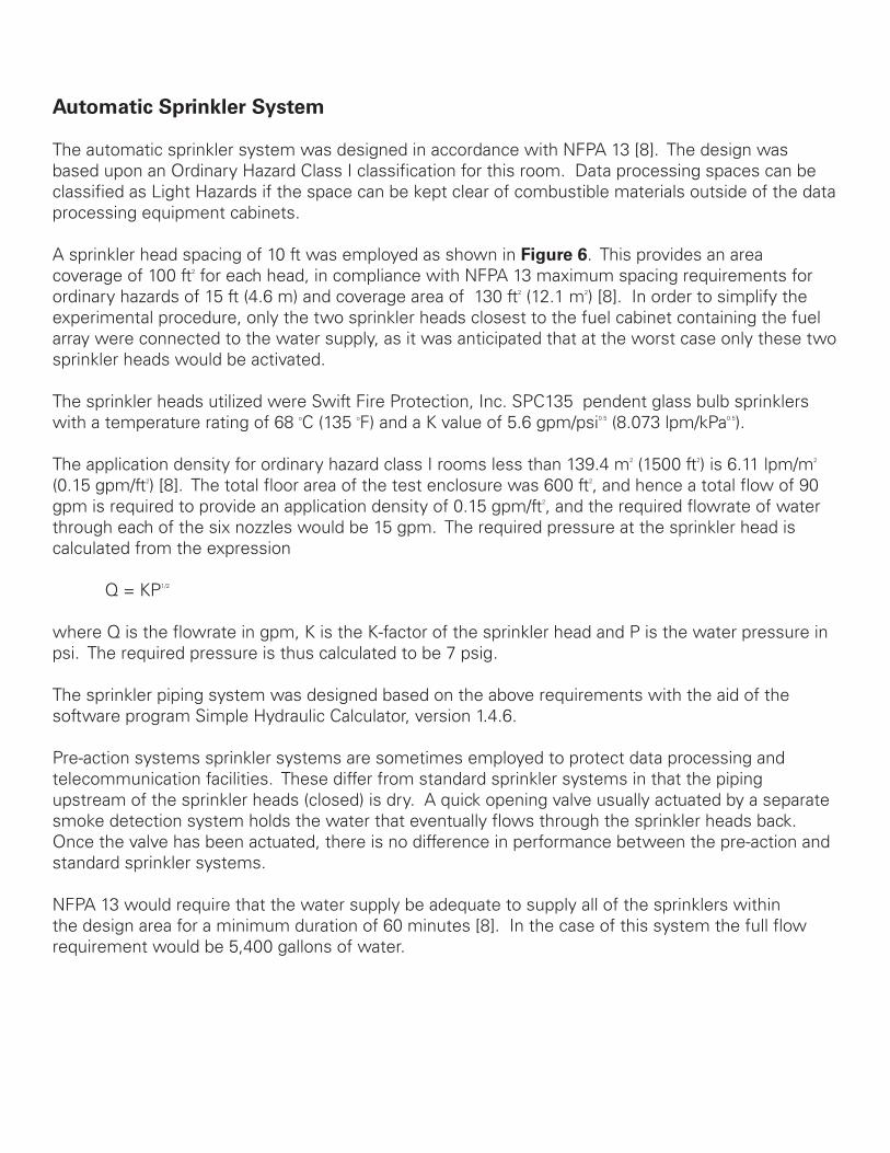
Post-test examination of the room revealed a black “ring” around the enclosure extending 2 to 3 ft (0.6 to 0.9 m) below the suspended ceiling, which was more pronounced near the fire location. Ceiling tiles were discolored, and the entire contents of the enclosure were covered with a fine soot and with water. The water in the enclosure contained floating soot particles which were scrubbed from the smoke layer as the water spray passed through the smoke layer. Figures 7 through 12 show views of the enclosure after the sprinkler system test.
The automatic sprinkler system operated as expected and met its objectives of limiting the ceiling temperatures to prevent structural damage and in preventing either flashover or spread of the fire outside of the cabinet containing the fuel array. As evidenced by Figures 7 through 12 and the discussion above, the damage to the enclosure was much more extensive than that resulting from the use of the FE-25TM system.
Figures 13 and 14 compare the ceiling temperatures observed during suppression with the FE-25TM system and the water sprinkler system, respectively. In the case of the FE-25TM system, ceiling temperatures did not rise above the initial ambient enclosure temperature. In contrast, for the sprinkler system, a maximum ceiling temperatures of 405 oF was observed.
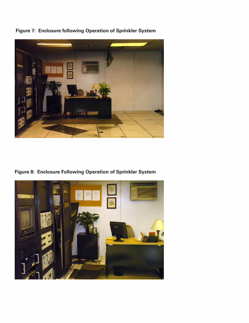
Figure 7: Enclosure following Operation of Sprinkler System
Figure 8: Enclosure Following Operation of Sprinkler System

Figure 9: Enclosure Following Operation of Sprinkler System
Figure 10: Enclosure Following Operation of Sprinkler System
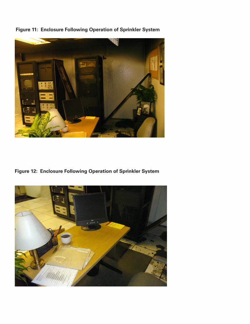
Figure 11: Enclosure Following Operation of Sprinkler System
Figure 12: Enclosure Following Operation of Sprinkler System

Figure 13: Ceiling Temperature, FE-25TM System
Ceiling Temperatures: FE-25 System/ABS Cabinet Fire
40
45
50
55
60
65
70
75
0 100 200 300
Time, seconds
Tem
pera
ture
, de
gree
s Fa
hren
heit
TC05 (F)TC06 (F)
Figure 14: Ceiling Temperature, Sprinkler System
Ceiling Temperatures: Sprinkler System/ABS Cabinet Fire
50
100
150
200
250
300
350
0 200 400 600 800 1000
Time, seconds
Tem
pera
ture
, de
gree
s Fa
hren
heit
TC05 (F)TC06 (F)

Comparison of FE-25TM and Sprinkler System Results
The test results obtained during this study clearly demonstrate the vast differences in protection provided by gaseous clean agent and automatic sprinkler systems. Both systems, designed and installed in accordance with the appropriate NFPA standards, performed exactly as expected based upon the primary design objective of the systems. Table 3 provide a comparison of the test results.
Table 4 summarizes the characteristics of gaseous clean agent and automatic sprinkler systems. The fundamental objective of the two systems is vastly different. The primary objective of an automatic sprinkler system is fire control: confining of the fire to the room of origin and controlling the ceiling temperatures to prevent structural damage and/or collapse. This is vastly different from the primary objective of a clean agent system, which is rapid fire extinguishment.
The primary objective of a clean agent system is to provide rapid detection and rapid extinguishment. This ensures the fire is still in its incipient stages and that damage is limited to the object(s) undergoing combustion. FE-25TM test results demonstrate the attainment of these objectives. The fire was rapidly detected (80-90 seconds after ignition), and after a 30 second delay the system was actuated, resulting in extinguishment 12 to 18 seconds later. At the time of system actuation, the fire size was approximately 20 kW, and the maximum ceiling temperatures recorded at the time of actuation were unchanged from the initial amount temperature of the enclosure. Damage to the enclosure and its contents were limited to a scorching of the equipment cabinet containing the fuel array, and the dislodging of several ceiling tiles.
The FE-25TM agent is a clean agent, i.e., no residues are left in the enclosure following extinguishment, and hence no post-extinguishment cleanup of the facility would be required. Business interruption would be kept to a minimum and repairs would consist solely of replacing or resetting several ceiling tiles and picking up papers blown onto the floor. As indicated above, employing a deflector shield or a nozzle with slightly downward directed orifices would likely eliminate the need for even these minor repairs.
The primary objective of a sprinkler system, whether wet-pipe or pre-action, is fire control, and the attainment of this objective was demonstrated during the automatic sprinkler test. The fire was contained to its place of origin, and the ceiling temperatures controlled sufficiently to prevent structural damage and/or collapse. Actuation of sprinkler systems does not occur until the temperature at the glass bulb or the fusible link of a sprinkler head exceeds its temperature rating, in this case 135 oF. Actuation of the sprinkler heads occurred at 324 and 410 seconds after ignition. At the time of the head activations the room was entirely filled with smoke and vision completely obscured. Ceiling jet temperatures at the sprinkler heads at the time of activation were in excess of 250 oF. A maximum ceiling temperature of 405 oF was observed.

Table 3: Comparison of Test Results for Suppression of ABS In-Cabinet Fire by FE-25TM and Sprinkler Systems
Sprinkler System FE-25TM SystemSystem activation (from ignition) 324 s 90 sFire Extinguishment Not extinguished < 10 s from EODFire Size at Activation 300 kW 20 kWCeiling Jet Temperature at Head At Activation 260 oF 78 oFMaximum Ceiling Temperature 405 oF 78 oFSmoke Damage Extensive noneWater Damage Extensive none
Table 4: Comparison of Clean Agent and Automatic Sprinkler Systems
Sprinkler System Clean Agent SystemSuppression Agent Water GasDesign Objective Fire Control:
Confine firesControl CeilingTemperature
Fire Extinguishment
Activation Sprinkler head T >135 oF
Automatic activation following detection (air sampling, smoke detectors)
Fire size at activation Can be 100’s of kW Low as 0.1 kW with Air sampling detection system
Total Flooding? No; water not three-dimensional, will notfill entire enclosure
Yes; agent distributed uniformlythroughout enclosure
Cleanliness Not clean; waterdamage can be extensive and exceedfire damage
Yes; no residues to clean up following extinguishment
Protection Protection of the structure not its high value contents
Protection of high value contents, not the structure
Relative Cost Low High

The sprinkler system failed to extinguish the fire, but this was an expected result, as the primary objective of the system is fire control. Unlike gaseous agents, water is not three-dimensional in nature and does not completely fill the enclosure, i.e., it does not act as a total flooding agent. Hence, fires in locations where the water spray does not directly impinge upon the fire would not be expected to be extinguished, but would be controlled by a properly designed automatic suppression system.
Although the initial cost of an automatic sprinkler system is much lower than that of a clean agent system, the results seen here demonstrate the potential risk associated with relying on a sprinkler system to provide protection for both the structure and its contents. In this case of an in-cabinet fire, both the asset and the structure suffered extensive damage when an automatic sprinkler was provided as the only protection. Extensive cleanup and repair of the structure would be required before the facility could be re-occupied and business resumed. As seen from the FE-25™ system test, this same in-cabinet fire could be readily extinguished without any accompanying damage to the structure or its contents. The higher price of the clean agent system is justified by the protection it provides for very sensitive and expensive equipment, and the ability of the clean agent system to minimize cleanup and business downtime.
Post-Extinguishment Atmosphere: FE-25TM System
FTIR analysis of the post-extinguishment atmosphere resulting from discharge of the FE-25TM system revealed only FE-25TM, carbon dioxide (CO2) and carbon monoxide (CO) to be present ; the CO was measured to be 14 ppm, a non-threatening level, and CO2 was unchanged from ambient levels.
The lack of significant combustion products is expected given the rapid detection and rapid extinguishment provided by the FE-25TM gaseous clean agent system.
Post-Extinguishment Atmosphere: Sprinkler System
Vapor phase species. Table 5 summarizes the peak concentrations for the gases measured in situ via FTIR during the sprinkler system tests. In addition to these compounds identified via in-situ FTIR, FTIR and GC-MS analysis of the vapor grab samples obtained during this test indicated the presence of the compounds shown in Table 8. In the case of the grab sample analyses, quantification of species present was not possible.
Tables 5 and 6 indicate the formation of numerous toxic products during the sprinkler test. Also shown in Table 5 are the Immediately Dangerous to Life or Health (IDLH) levels; the Occupational Safety and Health Administration (OSHA) defines an IDLH concentration in their hazardous waste operations and emergency response regulation as “an atmospheric concentration of any toxic, corrosive or asphyxiant substance that poses an immediate threat to life or would cause irreversible or delayed adverse health effects or would interfere with an individual’s ability to escape from a dangerous atmosphere.”

As seen from Table 5 concentrations exceeding the IDLH were observed for the combustion products carbon monoxide, hydrogen cyanide, nitric oxide, acetonitrile, acrylonitrile, and formaldehyde. It is important to note that in this test, the fire was manually extinguished with a portable extinguisher at approximately 10 minutes after ignition; if the response time for fire fighting personnel were longer, the concentrations of combustion products seen in Table 5 would increase, and additional products would be formed in concentrations exceeding their IDLH.
Table 5: Chemical Species Observed via in-situ FTIR in the Post-Extinguishment Atmosphere of the Sprinkler Test
Chemical Structure Peak Conc., ppm IDLH, ppmCarbon monoxide CO 1,344 1,200Carbon Dioxide CO2 18,847 40,000Hydrogen cyanide HCN 93 50Nitric oxide NO 50 50Nitrogen dioxide NO2 14 50Ethylene CH2=CH2 66 800Methane CH4 59 5,000Acetonitrile CH3CN 1,489 500Acrylonitrile CH2CH=CN 335 851,3-Butadiene CH2=CHCH=CH2 47 2,000Formaldehyde HCOH 21 20Styrene C6H5CH=CH2 122 700
Table 6: Chemical Species Observed via FTIR and GC/MS Analysis of Grab Samples from the Post-Extinguishment Atmosphere of the Sprinkler Test
Chemical StructureBenzene C6H6
Toluene C6H5CH3
Acetone CH3COCH3
Pentane CH3CH2CH2CH2CH3
Methyl Isobutyl Ketone CH3COCH(CH3)CH2CH3
Hexanal CH3CH2CH2CH2CH2CHO
Xylene C6H4(CH3)2

Solid Species. The solid soot samples collected from the test enclosure were examined by FTIR and Raman spectroscopies. This soot consisted of both black and white particles. The black soot products were identified as amorphous carbon and the white products identified as aromatic compounds, e.g., polystyrene.
Soot by itself is known to be capable of causing damage to delicate electronic equipment. Soot particles will also end up in the aqueous runoff resulting from the activation of the sprinkler system, and these soot particles, laden with carcinogenic aromatic compounds, will end up being deposited on articles within the enclosure and, in addition, are ultimately discharged into the local water system.
Aqueous Species. The water collected following the sprinkler test was examined via ion chromatography and found to contain fluoride (F-), chloride (Cl-), sulfate (SO4
3-), phosphate (PO43-), nitrite (NO2
-), nitrate (NO3-) and formate (HCOO-) anions. The aqueous sample was also found to be
acidic, pH = 4.
These aqueous species are corrosive and can lead to further damage of delicate equipment and assets. As is the case for the soot formed during the sprinkler system tests, these species will eventually be discharged into the local water system
CONCLUSION
A series of tests were performed in a simulated data processing/telecommunications facility to illustrate the difference in protection afforded by gaseous clean agent and automatic sprinkler systems. The results of these tests clearly demonstrate the vastly different nature of these systems. The purpose of a sprinkler system is to protect the structure, and to confine the fire to its room of origin. The purpose of a gaseous clean agent system is to protect the valuable and/or sensitive assets within the enclosure. As seen in this study, relying on a sprinkler system for protection of the enclosure’s assets can be ineffective and costly: not only can the asset which initially caught fire be destroyed, but extensive smoke and water damage to the enclosure and its contents can also result, leading to extensive cleanup and downtime.
In addition, high levels of toxic and corrosive combustion are produced, including soots, and these products are both released to the atmosphere and absorbed into the sprinkler water, presenting an environmental threat to both the local atmosphere and the local water supply. These species themselves can also lead to further damage of valuable assets stored within the protected facility.
At the same time, gaseous clean agent systems are not ideally suited for the protection of structures, but for the protection of the enclosure’s contents, typically very sensitive and expensive equipment, and provide a minimum of downtime and cleanup in the event of a fire. As a result, for applications involving expensive and sensitive equipment, the use of a gaseous clean agent to protect the assets, in combination with a sprinkler system to protect the structure, is a logical and viable solution to the fire protection needs of such facilities.

Copyright© 2008 DuPont or its affiliates. All rights reserved. The DuPont Oval Logo, DuPont™, FE-25™ and The miracles of science™ are trademarks or registered trademarks of E.I. du Pont de Nemours and Company or its affiliates.NO PART OF THIS MATERIAL MAY BE REPRODUCED, STORED IN A RETRIEVAL SYSTEM OR TRANSMITTED IN ANY FORM OR BY ANY MEANS ELECTRONIC, MECHANICAL, PHOTO-COPYING, RECORDING OR OTHERWISE WITHOUT THE PRIOR WRITTEN PERMISSION OF DUPONT.
REFERENCES
1. Underwriters Laboratories, Inc. “Standard for Halocarbon Clean Agent Extinguishing System Units”, UL 2166, Underwriters Laboratories, Northbrook, IL, 1999.
2. Robin, M.L. and Forssell, E.W., “Comparison Testing in a Simulated Data Processing/Telecommunications Facility: FM-200® and Automatic Sprinkler Systems,” Proc. 2004 Halon Options Technical Working Conference, May 2004.
3. National Fire Protection Association, “Standard Methods of Fire Tests for Evaluating Room Fire Growth Contributions of Textile Coverings on Full Height Panels and Walls”, NFPA 265, National Fire Protection Association, Quincy, MA, 2002.
4. National Fire Protection Association, “National Fire Alarm Code”, NFPA 72, National Fire Protection Association, Quincy, MA, 2002.
5. “FM Global Property Loss Prevention Sheets, Electronic Data Processing Systems”, Sheet 5-32, Factory Mutual Insurance Company, Norwood, MA, 2002.
6. “FM Global Property Loss Prevention Sheets, Telecommunications, Sheet 5-14, Factory Mutual Insurance Company, Norwood, MA, 1998.
7. National Fire Protection Association, “Standard on Clean Agent Extinguishing Systems”, NFPA 2001, National Fire Protection Association, Quincy, MA, 2008.
8. National Fire Protection Association, “Standard on Installation of Sprinkler Systems”, NFPA 13, National Fire Protection Association, Quincy, MA, 2004.
K-20166 (07/08)