durability planning for concrete on the ross river bridge
TRANSCRIPT

99
© Institution of Engineers Australia, 2012
* Paper C11-691 submitted 15/02/11; accepted for publication after review and revision 9/08/11.
† Corresponding author Marita Berndt can be contacted at [email protected].
Durability planning for concrete on
the Ross River Bridge, Townsville*
ML Berndt†
Aurecon Australia, Melbourne, Victoria;Centre for Sustainable Infrastructure, Faculty of Engineering and Industrial Sciences,
Swinburne University of Technology, Hawthorn, Victoria
PA ShawAECOM, Fortitude Valley, Queensland
ABSTRACT: The Ross River Bridge in Townsville is currently under construction and will be located in an aggressive environment at the river’s mouth. A durability plan was developed prior to construction in order to determine appropriate concrete design and construction practices to achieve the required design life of 100 years. Possible deterioration mechanisms investigated included: chloride ingress; carbonation; alkali-aggregate reaction (AAR); sulphate attack; acid sulphate soil degradation; atmospheric corrosion and corrosion of pile casings due to sulphate reducing bacteria. This paper outlines the approach undertaken to ensure that the bridge design met the required life. The results of mathematical modelling of chloride ingress and carbonation are presented based as both deterministic and probabilistic approaches. The concrete mix design was adjusted to address AAR and sulphate attack and appropriate testing was incorporated into the project specifi cations. The design approach outlined resulted in some durability requirements exceeding those nominated in AS5100.5 such as increased cover requirements and the need for stainless steel reinforcement.
KEYWORDS: Concrete; durability; corrosion; service life modelling.
REFERENCE: Berndt, M. L. & Shaw, P. A. 2012, “Durability planning for concrete on the Ross River Bridge, Townsville”, Australian Journal of Civil Engineering, Vol. 10, No. 2,pp. 99-116, http://dx.doi.org/10.7158/C11-691.2012.10.2.
1 INTRODUCTION
The Townsville Port Access Road will connect the Flinders and Bruce Highways to the Port of Townsville. The 10 km project consists of a new 2.5 km road linking the Flinders Highway to the Bruce Highway (Stuart Bypass) and a new 7.5 km road from the Bruce Highway to the Port (Eastern Access Corridor). As part of this road, a new bridge will be constructed across mouth of the Ross River. The bridge will be located close to the open sea and will therefore be exposed to tropical marine
conditions. The design life of the bridge is 100
years and as part of the project requirements, a
durability plan was developed to address potential
deterioration mechanisms and appropriate design
to achieve the target life. This paper describes the
approach used for predicting deterioration and
the durability measures. The paper is limited to
discussion of reinforced concrete although the full
durability plan included consideration of metallic
and polymeric materials.
2 DURABILITY PLAN PROCESS
The process used in development of a durability plan
for the project involved the following steps:
Australian Journal of Civil Engineering, Vol 10 No 2
C11-691 Berndt.indd 99C11-691 Berndt.indd 99 9/10/12 10:07 AM9/10/12 10:07 AM

100
Australian Journal of Civil Engineering Vol 10 No 2
“Durability planning for concrete on the Ross River Bridge, Townsville” – Berndt & Shaw
Identifi cation of bridge elements and required design life for each of these:
• Definition and classification of exposure environments for bridge elements
• Identification of potential deterioration mechanisms in exposure environments
• Prediction of likely deterioration rates
• Determination of measures required to achieve design life in service environment.
The definition of design life used for Ross River Bridge project was as stated in AS5100.1 (Standards Australia, 2004a). This standard defines design life as: “The period assumed in design for which a structure or structural element is required to perform its intended purpose without replacement or major structural repairs.” In general, relevant Australian standards and Queensland Transport and Main Roads (QTMR) design guidelines were followed in assessing the durability of the bridge and required protective measures. These standards include AS5100 (Standards Australia, 2004a; 2004b), AS2159 (Standards Australia, 2009), AS/NZ 2312 (Standards Australia, 2002) and AS4312 (Standards Australia, 2008). In some cases where specifi c exposure environments are not covered by the standards or QTMR requirements supersede these standards, such as complex or unusual soil chemistry, or where the durability recommendations or provisions in the codes/standards were identifi ed as being inadequate, then predictive modelling of key deterioration mechanisms was adopted to establish material performance over the nominated design life
to ensure compliance. The outcomes of the durability planning process for the concrete elements of the project are described in the following sections.
3 DESCRIPTION OF BRIDGE AND CLASSIFICATION OF EXPOSURE ENVIRONMENTS
The preferred option for the bridge is a six-span super tee girder structure. This will be supported by reinforced concrete headstocks, columns, pile caps and piles. Figure 1 shows the plan and elevation of the bridge. Piers 2, 3 and 4 will be located in the river and Piers 1 and 5 will be located on the river banks. The main river pier pile type is cast in-situ concrete with composite, steel liners. These are termed “Pipe Piles”. Other piles (Piers 1 and 5 and abutments) will be precast, prestressed concrete octagonal piles. The southern end of the bridge (Abutment A) will be constructed on tidal fl ats. The total length of the bridge is 191.2 m and the width is 14.7 m. The bridge deck will include a pedestrian/cycleway and the bridge soffi t will be 7 m above highest astronomical tide to allow for ship clearance.
The pile caps for Piers 2, 3 and 4 have been designed for ship impact and will have a stainless steel mesh with covers specifi ed between the stainless steel and carbon steel reinforcement. This should provide some protection against damage due to impact. The edge girders will have a steel beam mounted to the side of them to resist ship impact to the deck.
Fig ure 1: Plan and elevation of Ross River Bridge.
C11-691 Berndt.indd 100C11-691 Berndt.indd 100 9/10/12 10:07 AM9/10/12 10:07 AM

101
Australian Journal of Civil Engineering Vol 10 No 2
“Durability planning for concrete on the Ross River Bridge, Townsville” – Berndt & Shaw
The exposure environments for the bridge elements are summarised in table 1. A project requirement was that all concrete have a minimum AS5100.5 (Standards Australia, 2004b) exposure classifi cation of B2.
4 POTENTIAL DETERIORATION MECHANISMS CONSIDERED
Given the service environment for the Ross River Bridge, the major material durability issues to be considered were as follows:
• Reinforcement corrosion due to chloride ingress and/or carbonation
• Alkali-aggregate reaction (AAR) in concrete
• Sulphate attack in river water and buried concrete
• Acid sulphate soil degradation of buried concrete
• Atmospheric corrosion of metals
• Microbiologically infl uenced corrosion of buried steel pile casing due to sulphate reducing bacteria (SRB)
• Thermal cracking and delayed ettringite formation in concrete.
This paper covers reinforcement corrosion, AAR and sulphate attack of concrete. Deterioration of concrete due to contact with acid sulphate soils, prevention of thermal cracking and delayed ettringite formation and atmospheric corrosion of metals were considered in the detailed durability plan for the project and are not included in this paper due to space limitations.
Soil tests indicated the presence of SRB at variable concentrations and investigation indicated that
corrosion due to SRB was more likely in the upper stratum of the bridge foundations. The approach undertaken for the design of the steel “pipes” for the river piles was to assume that they were not structural down to RL –10 m and hence the impact of any microbiologically infl uenced corrosion due to SRB would not be signifi cant. Further information on corrosion by SRB is summarised by Shaw et al (2010).
4.1 Reinforcement corrosion
Generally, reinforcing steel embedded within concrete is in a passive state. However, if suffi cient build-up of chlorides at steel depth occurs, and/or if the alkalinity of concrete is reduced, this passive state will be lost and corrosion will be initiated. This is termed the corrosion initiation phase. Corrosion can then proceed in the subsequent propagation phase provided suffi cient water and oxygen are available to sustain the corrosion reactions. Since the corrosion products occupy signifi cantly greater volume than the original steel, this causes development of tensile stresses within the concrete that will ultimately result in cracking and spalling.
4.1.1 Chloride ingress
The mechanism of corrosion due to chloride ions is generally regarded as being due to localised breakdown of passive fi lms on steel embedded in concrete by a critical concentration of chlorides and resultant localised corrosion (Bertolini et al, 2004). The time to corrosion initiation will depend primarily on surface concentration of chlorides, pore water pH,
Table 1: Summary of concrete bridge element exposure environments and classification (note that minimum project requirement was B2).
Element Exposure environment AS5100.5 exposure classifi cation
Piles (abutments) Buried (clean fi ll/natural profi le) B2
Piles (Pier 1) Buried (clean fi ll/natural profi le) B2
Piles (Pier 5) Buried (river bank) U
Piles (Piers 2, 3 and 4) (steel encased)
Tidal/submerged/buried C/B2/U
Pile caps (Pier 1)Buried (clean fi ll, subject to inundation)/atmospheric
U/B2
Pile caps (Pier 5) Buried (river bank)/atmospheric U
Pile caps (Piers 2, 3 and 4) Tidal/splash C
Headstocks (Piers 1 to 5) Atmospheric B2
Pier columns (Piers 1 and 5) Atmospheric B2
Pier columns (Piers 2, 3 and 4) Atmospheric/splash B2/C
Abutments (headstocks and wingwalls)
Buried/atmospheric B2
Super tee girders Atmospheric B2
Deck Atmospheric B2
C11-691 Berndt.indd 101C11-691 Berndt.indd 101 9/10/12 10:07 AM9/10/12 10:07 AM

102
Australian Journal of Civil Engineering Vol 10 No 2
“Durability planning for concrete on the Ross River Bridge, Townsville” – Berndt & Shaw
depth of cover, chloride diffusion coeffi cient, voids at the steel surface and chloride binding characteristics of cement or any supplementary cementing materials in the concrete. Once initiated, the rate of corrosion will be controlled predominantly by moisture and oxygen content and concrete resistivity. The time to failure as manifested by spalling and cracking of the cover concrete will depend on mechanical and fracture properties of the concrete, presence of interfacial voids, in addition to geometric parameters such as bar diameter, bar spacing and depth of cover.
4.1.2 Carbonation
Carbonation of the concrete will occur gradually over the service life of structures exposed to interior or exterior atmospheric conditions. Pore water in uncarbonated concrete has a pH value around 12.6 to 13.5 and this provides a passive environment for embedded reinforcement. Carbon dioxide in the atmosphere or dissolved in water can react with the basic calcium hydroxide in concrete pore water. When the concrete becomes carbonated the pH can be reduced to approximately 8.3. A carbonation front of reduced pH progresses from the surface throughout the depth of the cover concrete. Once the concrete becomes carbonated to the depth of reinforcement, the passive iron oxide layer is no longer stable and corrosion can occur in the presence of suffi cient water and oxygen.
4.2 Alkali-aggregate reaction
Certain types of aggregates can become reactive in the presence of moisture and alkaline conditions, leading to the initiation of AAR. The most common reactive aggregates contain certain forms of silica which reacts with alkalis in a deleterious manner. Reactions may also occur with certain carbonates. In the case of alkali-silica reaction (ASR), a gel is formed around the rim of the aggregate particle or within pores and planes of the aggregate itself. The gel can absorb water and swell, thus resulting in development of internal pressure, expansion and cracking. Moisture is required for this form of cracking and can take several years (5-15 or more) to appear. Cracks due to AAR typically have a map pattern and the prominent cracks align parallel to the direction of maximum restraint. Pop-outs of individual aggregate particles may also be evident.
The quantity of reactive minerals and the physical properties of the aggregate, as well as the type and quantity of alkali within the cement, affect the level of reactivity. Certain Queensland aggregates are known to be susceptible to ASR. Shayan et al (1996) reviewed AAR in Australia. Examples of ASR in Queensland structures and its management were provided by Carse (1988; 2001) and Carse & Dux (1989). Furthermore, aggregates from the Roseneath quarry in Townsville have been shown to be reactive
when investigated in relation to ASR at Lucinda Jetty (Idorn, 1997; Thaulow et al, 1989; Andersen & Thaulow, 1990) and numerous cases of structures in the Townsville area suffering from ASR have been documented (Carse, 1988; 2001; 2003). The history of aggregates in the area with high ASR susceptibility deemed that recognition and prevention of this potential form of deterioration was essential.
4.3 Sulphate attack
Sulphates that may be present in groundwater, river water, seawater and soil can react with constituents of cement paste to cause expansion and deterioration. The reaction depends on the form of sulphate. Sodium sulphate reacts with calcium hydroxide to form gypsum and with calcium aluminate hydrate to form calcium sulphoaluminate (ettringite). The production of ettringite is an expansive reaction and eventually causes micro-cracking and disintegration of the cement binder. Calcium sulphate also reacts with calcium aluminate hydrate. Magnesium sulphate reacts with calcium silicate hydrates in addition to calcium aluminate hydrate and calcium hydroxide. Sulphate attack is discussed further by Skalny et al (2002).
The extent of damage due to sulphates will depend on the type and concentration of sulphate, amount of calcium aluminate hydrate in the cement, presence of supplementary cementing materials, and concrete quality. In addition, the presence of chlorides can be infl uential since chloride ions also react with calcium aluminate hydrate and form chloroaluminate compounds. This reaction reduces the amount of calcium aluminate hydrate available for reaction with sulphate ions. Since concrete substructure elements on the Ross River Bridge will potentially be exposed to sulphate-bearing river water and groundwater, the risk of sulphate attack was considered and addressed.
5 CONCRETE DURABILITY PREDICTIONS AND PROTECTIVE MEASURES REQUIRED TO ACHIEVE DESIGN LIFE
5.1 Assumed serviceability limit state
In the case of degradation caused by reinforcement corrosion, the assumed serviceability limit state is the onset of visible cracking. This corresponds with the initial appearance of surface cracks rather than extensive spalling or signifi cant loss of reinforcement cross-section due to corrosion that would require structural major repairs and is compatible with the AS5100 definition of design life. Therefore, the durability predictions considered the likely time to this damage and the protective measures required to prevent such damage within a design
C11-691 Berndt.indd 102C11-691 Berndt.indd 102 9/10/12 10:07 AM9/10/12 10:07 AM

103
Australian Journal of Civil Engineering Vol 10 No 2
“Durability planning for concrete on the Ross River Bridge, Townsville” – Berndt & Shaw
life period of 100 years. A serviceability limit state of initiation of corrosion or depassivation is regarded as overly conservative because a structure will still perform adequately for a period of time after corrosion commences and before cracking appears. The serviceability limit state definition used for the project differs from the ultimate limit state of structural failure or collapse.
The approach taken was to predict the time to corrosion initiation due to either chloride ingress or carbonation, depending on exposure conditions, based on diffusion principles and to estimate the corrosion propagation period to cause subsequent damage based on field observations in similar environments. In comparison to prediction of time to corrosion initiation, predictive modelling of the corrosion propagation period required to cause damage is poorly defi ned and lacks consensus. While advancements in the area of modelling have been made, the available models are often over-simplifi ed and unverifi ed. It is also considered that prediction of an exact propagation time is unrealistic due to the stochastic nature of corrosion and complexity of the resultant fracture process and that a probabilistic approach is more appropriate (Allan, 1995).
For this project corrosion propagation phases of 10 years in tidal/splash zones and 20 years in atmospheric zones were adopted based on field observations by the lead author on other structures in similar environments. This determines that a structure with a 100-year design life must not have corrosion initiated within 90 years for tidal/splash zones and 80 years for atmospheric zones. Buried environments have reduced oxygen access and, therefore, a reduced corrosion rate. Hence, for buried environments a corrosion propagation period of 20 years was also assumed.
For other forms of concrete deterioration such as sulphate attack and AAR, the assumed serviceability limit state is loss of strength or formation of excessive cracking and to cause loss of fi tness for purpose.
5.2 Chloride ingress
5.2.1 Modelling approach
Service life modelling is reviewed in numerous references, including Song & Shayan (2000). A simplifi ed approach towards prediction of the time to corrosion assumes that all transport of chloride occurs entirely by ionic diffusion. This approach was used for predicting chloride ingress in the current project. Other models have been proposed to account for phenomena such as chloride binding, convection, intermittent exposure, moisture content, and temperature (eg. Saetta et al, 1993; Andrade et al, 1997; Hansen & Saouma, 1999; Xi & Bažant, 1999; Tang & Nilsson, 2000; Nilsson, 2000; Ababneh et al, 2003). However, these more sophisticated models can
be problematic to implement in practical situations due to lack of sufficient information on input parameters and lack of verifi cation.
Diffusion can be modelled using a solution to Fick’s Second Law that takes into account the reduction in diffusion coeffi cient with time as shown in equation (1) (Luping & Gulikers, 2007). This equation allows the measured chloride diffusion coeffi cient from trial mixes to be incorporated in future predictions.
,
0
11
2(1 )
x t smm
ss
xc c erf
t tD t t
m t t
(1)
where cx,t = chloride concentration (%) at depth x and time t; cs = surface chloride concentration (%);D = diffusion coeffi cient at time of testing t
0 (m2/s);
t = time (s); t0 = test time (s); m = age factor; and ts =
age at start of exposure (s).
The primary strategy used in the project for achieving required design life for concrete susceptible to reinforcement corrosion was to have an appropriate combination of concrete chloride resistance and depth of cover to reinforcement. The steps used in the deterministic chloride ingress modelling were as follows:
• Select value of surface chloride concentration for exposure environment
• Select value of age factor for concrete mix proportions and exposure environment
• Use chloride diffusion coeffi cient test data from trial mixes
• Model chloride ingress using equation (1) for target minimum required time to corrosion initiation
• Compare modelled chloride concentrations with corrosion threshold values and determine if design depth of cover is suffi cient to prevent corrosion initiation within required life. If not, determine required increase in cover or consider alternative options such as stainless steel reinforcement.
5.2.2 River water tidal/splash exposure
5.2.2.1 Pile caps and pier columns
The tidal nature of Ross River and its connection to the sea indicate that the bridge piers and pile caps will be exposed to chloride ingress. Given the location of the bridge near the mouth of the river, it was assumed that the river water chemistry is equivalent to seawater and would therefore have a chloride concentration of approximately 19,000 ppm.
C11-691 Berndt.indd 103C11-691 Berndt.indd 103 9/10/12 10:07 AM9/10/12 10:07 AM

104
Australian Journal of Civil Engineering Vol 10 No 2
“Durability planning for concrete on the Ross River Bridge, Townsville” – Berndt & Shaw
Two S50 (50 MPa) concrete mixes were considered in fi eld trials for use on the bridge. In this project S50 refers to concrete with water/cementitious material ratio (w/cm) < 0.40 and minimum cementitious content of 450 kg/m3. The mixes were (a) 25% fl y ash for precast concrete, and (b) 25% fl y ash and 8% silica fume for cast in-situ concrete. Chloride diffusion testing in accordance with NordTest NT Build 443 was performed and subsequently used in modelling. The mixes are summarised in table 2. Note that the diffusion coeffi cients were measured after 35 days of exposure to chloride solution. It was expected that the use of silica fume would have reduced the diffusion coeffi cient despite the higher w/cm ratio as would be predicted from results by Hooton et al (1997). The reason for the increased diffusion coeffi cient was not clear and requires further investigation.
With respect to surface chloride concentration in equation (1), this largely depends on the exposure environment in addition to the presence of supplementary cementitious materials. For marine environments, surface chloride concentrations of concrete in seawater typically range between 0.5 and 0.75% by weight of concrete and values tend to be in the higher end of the range for blended cements (eg. Bamforth, 1996; 2004; Lee & Chisholm, 2005; Bertolini et al, 2004; Lay et al, 2003). Field investigations by the lead author on concrete piles exposed to seawater in the far north Queensland area have shown that the surface chloride concentration in ordinary Portland cement concrete is usually around 0.5% by weight of concrete. Bamforth (2004) suggested that concrete containing fl y ash has surface chloride concentrations 35% higher than for ordinary Portland cement concrete and that silica fume has a marginal effect of surface chloride concentration at w/cm ratios below 0.5. Therefore, a surface chloride concentration value of 0.65% by weight of concrete was assumed for concrete containing fl y ash and silica fume and exposed to river water tidal/splash.
The age factor m in equation (1) is dependent on exposure environment in addition to concrete mix design. Owing to the sensitivity of equation (1) to m, a conservative value of 0.4 was selected for both mixes based on published data and predictive models (eg. Life-365, 2008; Bamforth, 1999; Thomas
Table 2: Concrete mix designs and diffusion coefficients from trial mixes.
Mix 1 (precast concrete) Mix 2 (cast in-situ concrete)
Total cementitious material (kg/m3) 535 490
% fl y ash 25 25
% silica fume 0 8
Water/cementitious material ratio 0.31 0.40
28-day compressive strength (MPa) 78.5 81.8
Chloride diffusion coeffi cient (Nord Test NT Build 443 at 35 days) (m2/s)
2.09 × 10⁻¹² 2.79 × 10⁻¹²
Depth of Cover (mm)
0 10 20 30 40 50 60 70 80 90 100Chl
orid
e C
once
ntra
tion
(% b
y w
t. co
ncre
te)
0.0
0.1
0.2
0.3
0.4
0.5
0.6
0.725% Fly Ash, 8% Silica Fume, D = 2.79 x 10⁻¹² m2/s
316 LN
Black Steel
Fig ure 2: Predicted chloride concentration versus depth of cover after 90 years for S50 concrete in river water tidal/splash zone. Assumed corrosion thresholds for black steel and 316LN stainless steel indicated.
& Bamforth, 1999; Thomas et al, 1999; 2008; Lindvall, 2001; Lee & Chisholm, 2005; Nokken et al, 2006; Dao et al, 2010; Oslakovic et al, 2010). Silica fume was assumed to not have a major effect on the age factor. Although exposure environment infl uences the age factor, there is limited published quantitative data on this aspect. Therefore, the age factor was kept constant and conservative for different exposure environments considered.
Equation (1) was used to predict chloride ingress after 90 years of exposure. The test duration for the assumed initial diffusion coeffi cient was 35 days and the age at the time of exposure was seven days for cast in-situ concrete. This assumed that formwork would be kept in place for seven days. No additional curing was assumed. The results are presented in fi gure 2.
The assumed corrosion threshold concentration for black steel of 0.06% by weight of concrete is shown in fi gure 2. This value was based on the review by Bertolini et al (2004). However, it has also been determined that supplementary cementitious materials such as fl y ash may affect the corrosion threshold concentration (Bamforth, 2004) although it is diffi cult to predict a specifi c threshold value for any given mix. The threshold chloride concentration assumed for Type
C11-691 Berndt.indd 104C11-691 Berndt.indd 104 9/10/12 10:07 AM9/10/12 10:07 AM
105
Australian Journal of Civil Engineering Vol 10 No 2
“Durability planning for concrete on the Ross River Bridge, Townsville” – Berndt & Shaw
316L/ LN stainless steel reinforcement (low carbon, nitrogen enhanced version of Type 316 with better welding properties) was 0.5% by weight of concrete based on recommendations by the Life-365 model. This value is regarded as conservative since other data suggest that the value may be higher, particularly if the bars are pickled (Bertolini et al, 2004; Clemeña & Virmani, 2004; Hurley & Scully, 2006). Further information on the use of stainless steel reinforcement is provided in a guidance document from the Concrete Society (1998).
Based on fi gure 1, the required depths of cover to black steel on a deterministic basis are estimated to be 75 mm for the 25% fl y ash/8% silica fume mix in the river water tidal/splash zone. The use of 316LN stainless steel would enable signifi cant reductions in required cover.
In order to take into account the limitations of the above deterministic model and the uncertainties associated with input values such as corrosion threshold concentration, a probabilistic approach to modelling of chloride ingress was also considered. Doing so enabled a more realistic assessment of the adequacy of proposed protective measures given the inherent variability of concrete.
The reliability index can be calculated and this is a simple way of presenting probabilistic durability analyses. Probabilistic or reliability analysis requires defi nition of a limit state function to describe failure. The limit state is reached when the load (S) equals the resistance (R) of the system or structure. This can also be referred to the stress-strength approach. Failure occurs when load exceeds resistance. In the analysis in this paper, failure refers to initiation of corrosion rather than structural failure. The probability of failure (Pf) is given by:
Pf = P(R ≤ S) = P(R – S ≤ 0) = P(Z(R, S) ≤ 0) (2)
where Z(R, S) = R – S is the limit state function.
Reliability is defi ned as the probability of success, or probability of survival, Ps:
Ps = 1 – Pf (3)
Assuming that both S and R can be expressed as normal distributions, the mean of Z is:
μZ = μR – μS (4)
The standard deviation of Z is:
σZ = (σR2 + σS
2)0.5 (5)
The reliability index, β, is given by:
β = μZ/σZ (6)
The failure probability is expressed as:
Pf = Φ(–β) (7)
where Φ = standard normal cumulative distribution function.
The reliability index for concrete in the tidal/splash zone was calculated for different depths of cover. This was based on the fi rst-order reliability method. The variables were assumed to be normally distributed. Some publications (eg. FIB, 2006) suggest that some variables may be described by other distributions such as beta. However, normal distributions have been selected in the current analysis. The target reliability index was 1.28 and corresponds to a 10% probability of failure where failure refers to initiation of corrosion within 90 years rather than any loss of structural capacity. A 10% failure probability, or rounded up reliability index of 1.3 is recommended for a serviceability limit state of depassivation for an exposure class of seawater in FIB (2006).
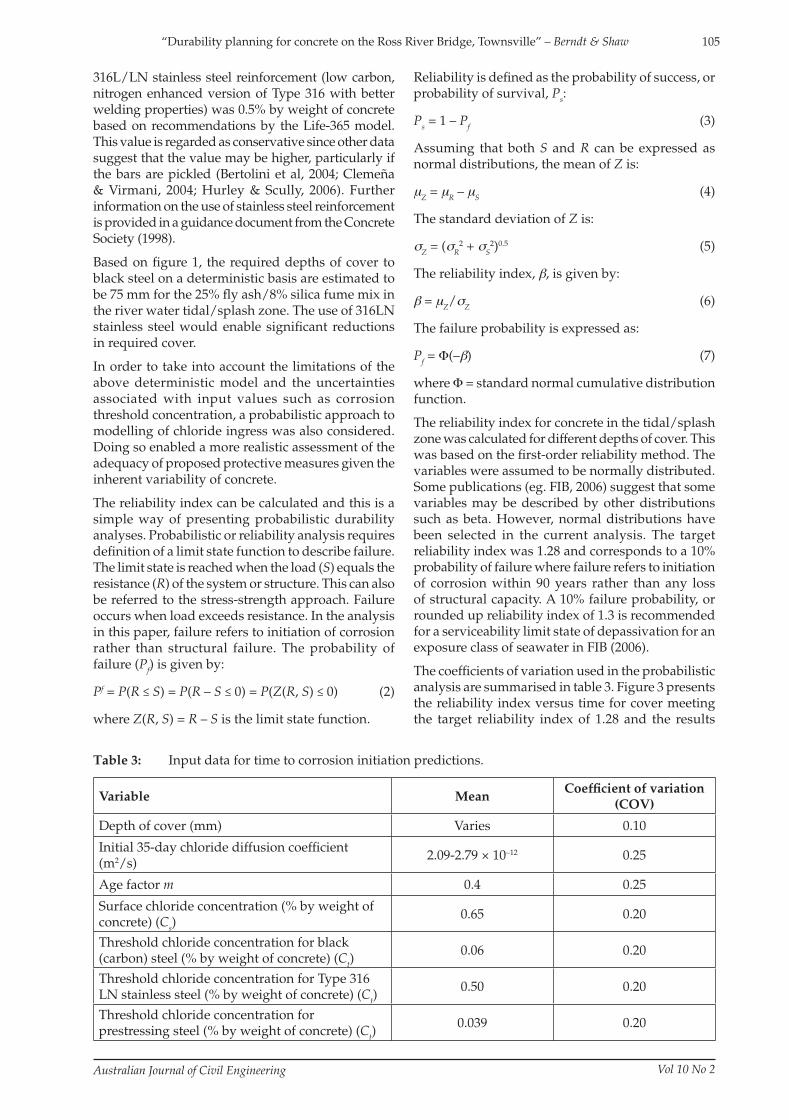
The coeffi cients of variation used in the probabilistic analysis are summarised in table 3. Figure 3 presents the reliability index versus time for cover meeting the target reliability index of 1.28 and the results
Table 3: Input data for time to corrosion initiation predictions.
Variable MeanCoeffi cient of variation
(COV)
Depth of cover (mm) Varies 0.10
Initial 35-day chloride diffusion coeffi cient (m2/s)
2.09-2.79 × 10⁻¹² 0.25
Age factor m 0.4 0.25
Surface chloride concentration (% by weight of concrete) (Cs)
0.65 0.20
Threshold chloride concentration for black (carbon) steel (% by weight of concrete) (Ct)
0.06 0.20
Threshold chloride concentration for Type 316 LN stainless steel (% by weight of concrete) (Ct)
0.50 0.20
Threshold chloride concentration for prestressing steel (% by weight of concrete) (Ct)
0.039 0.20
C11-691 Berndt.indd 105C11-691 Berndt.indd 105 9/10/12 10:07 AM9/10/12 10:07 AM

106
Australian Journal of Civil Engineering Vol 10 No 2
“Durability planning for concrete on the Ross River Bridge, Townsville” – Berndt & Shaw
are summarised in table 4. In the calculations the required cover was rounded up to the nearest 5 mm for practical purposes. In comparison, AS5100.5 (Standards Australia, 2004b) recommends nominal cover for a given exposure classification with tolerances. The probabilistic approach used for this project assumes a mean cover with coeffi cient of variation selected to represent tolerances achievable in construction.
In addition to calculating required cover for the proposed concrete mix designs, a project requirement was that bridge elements in salt water or tidal zones have provision for future cathodic protection if required for corrosion control. This entails making the reinforcement electrically continuous. Thus, cathodic protection can be implemented in the future should inspection and monitoring indicate premature corrosion activity.
5.2.2.2 Pipe piles
The pipe piles at Piers 2, 3, and 4 where the steel liner extends into the pile cap will also be exposed to the tidal/splash zone of the river. The proposed depth of cover to reinforcement in the pipe piles was 70 mm. The time at which the concrete inside the pipe piles is directly exposed to chlorides will depend on the corrosion rate of the steel casing. The
Table 4: Summary of required cover in tidal/splash zone for 90 years to corrosion initiation.
Element/s Concrete mixReinforcement
typeRequired
cover (mm)AS5100.5 cover
(mm)
Pile caps (Piers 2, 3 and 4)S50 25% fl y ash + 8% silica fume (Mix 2)
Black steel 85 70
Pier columns (Piers 2, 3 and 4) (steel encased)
S50 25% fl y ash + 8% silica fume (Mix 2)
Black steel 70 70
Pile caps (Piers 2, 3 and 4)S50 25% fl y ash + 8% silica fume (Mix 2)
316LN 30 N/A
Time (years)
0 20 40 60 80 100
Rel
iabi
lity
Inde
x
0
1
2
3
4
5
6Black Steel, 85 mm cover316LN, 30 mm cover
= 1.28
Fig ure 3: Reliability index versus time for s50 25% fly ash + 8% silica fume concrete in tidal/splash zone with required cover for different types of reinforcement. Target reliability index of 1.28 indicated.
corrosion rate, in turn, will depend on many factors such as water chemistry, velocity and temperature. Corrosion allowances for steel piles in seawater splash and tidal zones of 0.1-0.5 mm/a are given in AS2159 (Standards Australia, 2009). Data reported by Smith et al (2002) indicated corrosion rates of steel in marine splash zones typically around 0.2 mm/a. An assumed corrosion rate of 0.2 mm/a would predict complete corrosion of the 20 mm thick steel casing after 100 years whereas a rate of 0.5 mm/a would predict that the casing is completely corroded in 40 years. For the latter scenario, the concrete would be directly exposed to river water when it is at an age of 40 years and a further 50-year service life would be required to achieve a total time to corrosion initiation of 90 years.
Modelling was performed for cast in-situ concrete with an initial diffusion coeffi cient of 2.79 × 10⁻¹² m2/s. For an age factor of 0.4, the concrete should mature to have a diffusion coeffi cient of 3.4 × 10⁻¹³ m2/s by 30 years and remain constant thereafter. Thus, no further reduction in diffusion coeffi cient with time was used in the calculation. Analysis showed that the proposed depth of cover to reinforcement in the pipe piles of 70 mm should be adequate to achieve the required life.
5.2.3 River water permanently submerged exposure
Water saturated concrete has restricted oxygen availability and this affects both the corrosion threshold and the rate of corrosion if corrosion is initiated. The chloride threshold concentration is predicted to be up to one order of magnitude higher for submerged reinforced concrete compared with atmospheric (Bertolini et al, 2004). Fredericksen (2003) summarised published data on threshold values for submerged concrete and recommends concentrations of 1.0-2.0% by weight of cement (~0.18-0.37% by weight of concrete depending on mix proportions) for concrete with w/cm ratio = 0.4. This signifi cantly increases the corrosion initiation time. It is also practical experience that permanently submerged concrete elements do not typically exhibit cracking and spalling due to reinforcement corrosion due to lower oxygen concentration and that such deterioration is favoured in the tidal/splash zones. Consequently, the risk of damage due to reinforcement corrosion in
C11-691 Berndt.indd 106C11-691 Berndt.indd 106 9/10/12 10:07 AM9/10/12 10:07 AM

107
Australian Journal of Civil Engineering Vol 10 No 2
“Durability planning for concrete on the Ross River Bridge, Townsville” – Berndt & Shaw
permanently submerged concrete elements (ie. pipe piles at Piers 2, 3 and 4) was considered to be very low. The steel casing will also provide protection against direct exposure of concrete for a period of time.
Concrete quality and cover requirements as per AS5100.5 (Standards Australia, 2004b) for concrete permanently submerged in seawater were considered adequate. These requirements are summarised in table 5. However, the requirements for the tidal/splash zone and buried sections of the piles dominate the design.
5.2.4 Buried exposure
Buried concrete at the embankments and under the river is potentially subjected to elevated chloride concentrations. The different buried concrete elements are considered below.
5.2.4.1 Prestressed piles
At the abutments the concrete will be surrounded by clean fi ll and not exposed to river water ingress. Precast prestressed concrete piles were proposed for the abutments and Piers 1 and 5. Soil analysis from boreholes in natural soil showed chloride concentrations up to 10,800 ppm in the area. The Pier 1 piles and pile cap were to be located in clean fi ll. However, proximity to the river bank suggested that these would be subject to periodic inundation during fl ood events. Hence, the fi ll may initially be non-aggressive but would probably increase in chloride and sulphate concentrations with time.
While there is much published data for seawater exposure conditions, equivalent surface chloride concentration data for buried concrete in soils with different chloride concentrations has not been found. Evaporative effects that may concentrate chlorides on the surface as may occur in tidal and splash zones will be less apparent in deeply buried elements. As an approximation, the surface chloride concentration was assumed to be proportional to that for seawater with chloride concentration of 19,000 ppm. Soil chloride concentrations up to 10,800 ppm were measured at the site. Using this value as an upper limit gives an estimated surface chloride concentration of 0.37% by weight of concrete. Further research is required to better establish surface chloride concentrations and likely corrosion rates in buried conditions.
The chloride threshold value for prestressed concrete is less well defi ned and is assumed to be lower than
Table 5: Summary of required cover in permanently submerged zone for 80 yearsto corrosion initiation.
Element/s Concrete mixRequired cover
(mm)AS5100.5 cover
(mm)
Piles (Piers 2, 3 and 4) S50 25% fl y ash + 8% silica fume (Mix 2) 45 45
Depth of Cover (mm)
0 10 20 30 40 50 60 70 80 90 100Chl
orid
e C
once
ntra
tion
(% b
y w
t. co
ncre
te)
0.0
0.1
0.2
0.3
0.4
S50 25% FA, D = 2.09 x 10⁻¹² m2/s
Black SteelPrestressing Steel
Fig ure 4: Predicted chloride concentration versus depth of cover after 80 years for buried prestressed piles. Assumed corrosion thresholds for black and pre-stressing steel indicated.
the value for reinforced concrete. Use of a lower threshold is based on a number of factors including the consequences of corrosion (catastrophic failure of the pre-stressing strands) and susceptibility to stress corrosion cracking as discussed in ACI 222R-01 (ACI, 2001). Also, lower threshold values are based on research fi ndings or critical chloride concentrations around 0.17% by weight of cement (Stark, 1984). Assuming a minimum cementitious content of 535 kg/m3 and concrete density of 2350 kg/m3 for S50 precast prestressed piles, a threshold of 0.17% by weight of cement converts to 0.039% by weight of concrete.
Prediction of chloride ingress for buried conditions after 80 years for the S50 25% fl y ash precast concrete mix in table 2 is depicted in figure 4. Note that this curve is for prestressed concrete piles directly exposed to soil. For concrete fi lled steel pipe piles proposed for the river piles (Piers 2, 3 and 4) the steel casing will provide protection against chloride ingress until the steel is perforated due to corrosion. These are covered in section 5.2.4.2.
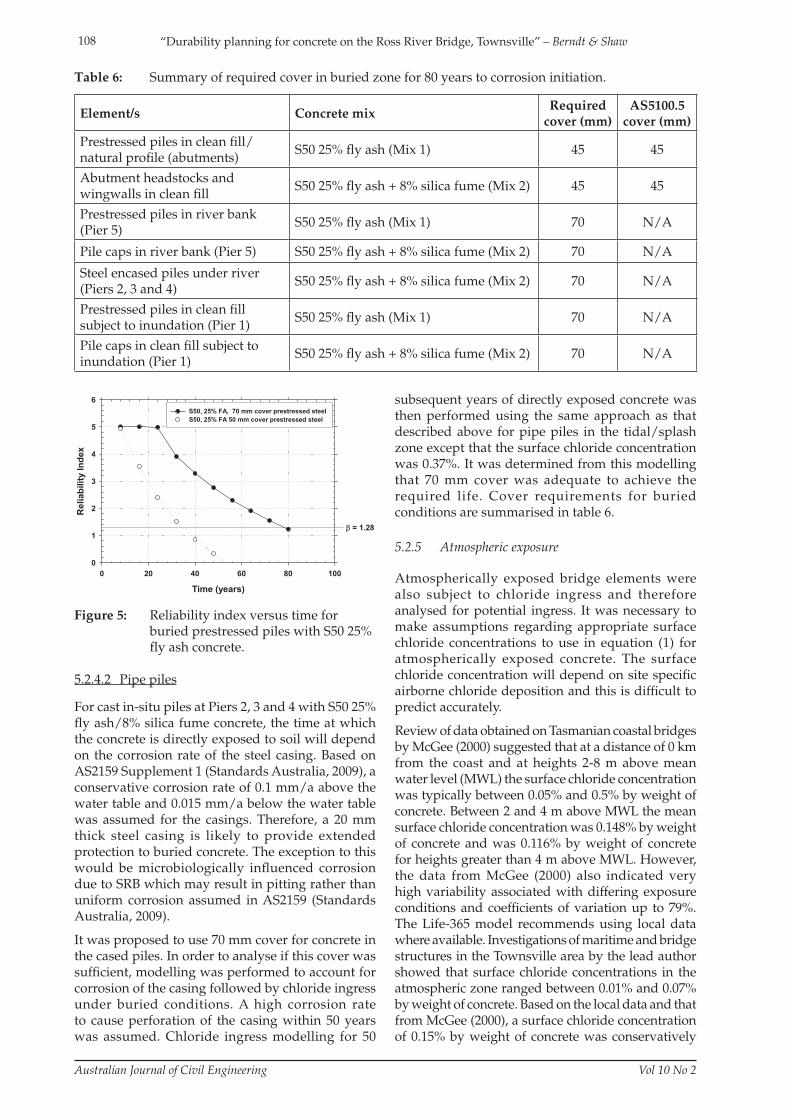
Reliability analysis for prestressed piles with S50 25% fl y ash concrete at Piers 1 and 5 was performed and is presented in fi gure 5. The analysis showed that 70 mm cover would be required for the prestressed piles and that the standard cover of 50 mm would be inadequate. Cover requirements are summarised in table 6. Note that some of the specifi c exposure environments are not covered in AS5100.5 (Standards Australia, 2004b) or would have a U classifi cation. Hence, the cover requirements as per AS5100.5 are not applicable as indicated in table 6.
C11-691 Berndt.indd 107C11-691 Berndt.indd 107 9/10/12 10:07 AM9/10/12 10:07 AM
108
Australian Journal of Civil Engineering Vol 10 No 2
“Durability planning for concrete on the Ross River Bridge, Townsville” – Berndt & Shaw
5.2.4.2 Pipe piles
For cast in-situ piles at Piers 2, 3 and 4 with S50 25% fl y ash/8% silica fume concrete, the time at which the concrete is directly exposed to soil will depend on the corrosion rate of the steel casing. Based on AS2159 Supplement 1 (Standards Australia, 2009), a conservative corrosion rate of 0.1 mm/a above the water table and 0.015 mm/a below the water table was assumed for the casings. Therefore, a 20 mm thick steel casing is likely to provide extended protection to buried concrete. The exception to this would be microbiologically infl uenced corrosion due to SRB which may result in pitting rather than uniform corrosion assumed in AS2159 (Standards Australia, 2009).
It was proposed to use 70 mm cover for concrete in the cased piles. In order to analyse if this cover was suffi cient, modelling was performed to account for corrosion of the casing followed by chloride ingress under buried conditions. A high corrosion rate to cause perforation of the casing within 50 years was assumed. Chloride ingress modelling for 50
Table 6: Summary of required cover in buried zone for 80 years to corrosion initiation.
Element/s Concrete mixRequired
cover (mm)AS5100.5
cover (mm)
Prestressed piles in clean fi ll/natural profi le (abutments)
S50 25% fl y ash (Mix 1) 45 45
Abutment headstocks and wingwalls in clean fi ll
S50 25% fl y ash + 8% silica fume (Mix 2) 45 45
Prestressed piles in river bank (Pier 5)
S50 25% fl y ash (Mix 1) 70 N/A
Pile caps in river bank (Pier 5) S50 25% fl y ash + 8% silica fume (Mix 2) 70 N/A
Steel encased piles under river (Piers 2, 3 and 4)
S50 25% fl y ash + 8% silica fume (Mix 2) 70 N/A
Prestressed piles in clean fi ll subject to inundation (Pier 1)
S50 25% fl y ash (Mix 1) 70 N/A
Pile caps in clean fi ll subject to inundation (Pier 1)
S50 25% fl y ash + 8% silica fume (Mix 2) 70 N/A
Time (years)
0 20 40 60 80 100
Rel
iabi
lity
Inde
x
0
1
2
3
4
5
6S50, 25% FA, 70 mm cover prestressed steel S50, 25% FA 50 mm cover prestressed steel
= 1.28
Fig ure 5: Reliability index versus time for buried prestressed piles with S50 25% fly ash concrete.
subsequent years of directly exposed concrete was then performed using the same approach as that described above for pipe piles in the tidal/splash zone except that the surface chloride concentration was 0.37%. It was determined from this modelling that 70 mm cover was adequate to achieve the required life. Cover requirements for buried conditions are summarised in table 6.
5.2.5 Atmospheric exposure
Atmospherically exposed bridge elements were also subject to chloride ingress and therefore analysed for potential ingress. It was necessary to make assumptions regarding appropriate surface chloride concentrations to use in equation (1) for atmospherically exposed concrete. The surface chloride concentration will depend on site specifi c airborne chloride deposition and this is diffi cult to predict accurately.
Review of data obtained on Tasmanian coastal bridges by McGee (2000) suggested that at a distance of 0 km from the coast and at heights 2-8 m above mean water level (MWL) the surface chloride concentration was typically between 0.05% and 0.5% by weight of concrete. Between 2 and 4 m above MWL the mean surface chloride concentration was 0.148% by weight of concrete and was 0.116% by weight of concrete for heights greater than 4 m above MWL. However, the data from McGee (2000) also indicated very high variability associated with differing exposure conditions and coeffi cients of variation up to 79%. The Life-365 model recommends using local data where available. Investigations of maritime and bridge structures in the Townsville area by the lead author showed that surface chloride concentrations in the atmospheric zone ranged between 0.01% and 0.07% by weight of concrete. Based on the local data and that from McGee (2000), a surface chloride concentration of 0.15% by weight of concrete was conservatively
C11-691 Berndt.indd 108C11-691 Berndt.indd 108 9/10/12 10:07 AM9/10/12 10:07 AM

109
Australian Journal of Civil Engineering Vol 10 No 2
“Durability planning for concrete on the Ross River Bridge, Townsville” – Berndt & Shaw
assumed for atmospherically exposed pier columns and a concentration of 0.08% by weight of concrete was assumed for headstocks, wingwalls, deck elements and super tee girders of the Ross River Bridge.
The resultant deterministic chloride ingress modelling predicted that AS5100.5 B2 cover of 45 mm for atmospherically exposed cast in-situ S50 concrete with standard formwork and compaction would be adequate to achieve a time to corrosion initiation of at least 80 years. This was confi rmed by probabilistic analysis to achieve a reliability index of 1.28.
For precast concrete produced with rigid formwork and intense compaction, AS5100.5 (Standards Australia, 2004b) allows for cover reduction to 35 mm for S50 concrete. This assumes that there is a reduction in chloride diffusion coefficient with such compaction and although this is logical there is a lack of specifi c published data allowing for quantification of such a reduction. Work by Bader (2003) described the impact of consolidation “effort” on chloride diffusion coeffi cient but it was not clear how this effort was measured and how it would translate to the types of compaction given in AS5100.5 (Standards Australia, 2004b). Therefore, no reduction in diffusion coeffi cient was assumed for the modelling. Reliability analysis for precast prestressed concrete (eg. super tee girders) predicted that 35 mm cover would be adequate for chloride resistance for a low assumed surface chloride concentration. Cover requirements for concrete exposed to airborne chlorides are summarised in table 7.
Given the uncertainty regarding the value of the actual surface chloride concentration in the atmospheric zone for the bridge, it was recommended that this be verifi ed by testing after the bridge has been in service for fi ve years. Such testing would permit additional modelling representative of the exposure conditions
and identify any need for actions such as application of a silane impregnate to reduce chloride ingress.
5.3 Carbonation
In the case of atmospherically exposed concrete, carbonation also has to be considered as a potential cause of reinforcement corrosion. Therefore, modelling was undertaken as part of the durability planning process to determine measures necessary to achieve design life.
5.3.1 Modelling approach
The rate of carbonation is typically expressed by equation (8) (Bertolini et al, 2004). As was the case for chloride ingress modelling, more sophisticated models for carbonation exist which take into account additional infl uences such as environmental exposure, microclimatic effects and degree of curing (eg. Galan & Andrade; 2009; CEB, 1997; FIB, 2006). However, equation (8) has been found to be suitable and practical for indicative carbonation prediction of atmospherically exposed concrete.
Depth of carbonation (mm) = Ct0.5 (8)
where C = carbonation rate or coeffi cient (mm/ year0.5) and t = time (years).
5.3.2 Carbonation predictions foratmospheric exposure
In order to predict the depth of carbonation it is necessary to consider an appropriate estimate of the carbonation coeffi cient in the service environment for the proposed concrete. The estimated carbonation rates used in the modelling are summarised in table 8 and have been derived from published results for
Table 7: Summary of required cover in atmospheric zone for 80 years to corrosion initiation by chloride ingress.
Element/s Concrete mixRequired
cover (mm)AS5100.5 cover for B2 exposure (mm)
Precast super tee girders S50, 25% fl y ash (Mix 1) 3535 (precast with
intense compaction)
Headstocks (Piers 1-5), abutment headstocks and wingwalls, pile caps (Piers 1 and 5), pier columns (Piers 1-5)
S50, 25% fl y ash + 8% silica fume (Mix 2)
45 45 (cast in-situ)
Cast in-situ deck elementsS50, 25% fl y ash + 8% silica fume (Mix 2)
45 45
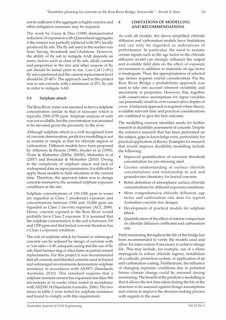
Table 8: Estimated carbonation coefficients for modelling.
Concrete mix Carbonation coeffi cient (mm/year0.5)
S50, 25% fl y ash 3.0
S50, 25% fl y ash, 8% silica fume 2.0
C11-691 Berndt.indd 109C11-691 Berndt.indd 109 9/10/12 10:07 AM9/10/12 10:07 AM

110
Australian Journal of Civil Engineering Vol 10 No 2
“Durability planning for concrete on the Ross River Bridge, Townsville” – Berndt & Shaw
The reliability analysis suggested that cast in-situ S50 25% fl y ash/8% silica fume concrete that conforms to the B2 minimum cover requirements in AS5100.5 of 45 mm for standard formwork and compaction would be adequate for resistance to reinforcement corrosion caused by carbonation. While carbonation predictions suggested that lower cover may be suffi cient for cast in-situ concrete, the project requirement of B2 exposure classifi cation and chloride resistance requirements necessitated higher cover. Table 9 summarises cover requirements for carbonation resistance.
Cover of 35 mm for precast S50 25% fl y ash concrete with rigid formwork and intense compaction in a B2 exposure classifi cation as per AS5100.5 (Standards Australia, 2004b) was determined to be adequate for carbonation resistance. Gonen & Yazicioglu (2007) studied the infl uence of compaction on carbonation. However, the tests compared uncompacted and rodded cylinders rather than concrete compacted using mechanical vibrators. The effect of intense compaction on carbonation rate does not appear to be documented in published literature and reductions in cover associated with such compaction and this is an area requiring further research to quantify the effect.
Carbonation testing throughout the life of the bridge has also been recommended to verify the modelling and, if necessary, identify the need for protective measures such as application of an anti-carbonation coating. This may be necessary if atmospheric carbon dioxide concentrations become signifi cant due to climate change.
5.4 Alkali-aggregate reaction
Expansion and cracking due to AAR are not readily modelled, predictable or controllable. Therefore, the strategy taken in durability planning for the Ross River Bridge was to avoid AAR. In general, AAR damage can be prevented by proper testing and selection of aggregate as per AS2758.1 (Standards Australia, 1998) and limiting the total mass of reactive alkali in the concrete to less than 2.5 kg/m3. The use of low alkali (0.6% Na
2O equivalent) cements as
specifi ed in AS5100 is necessary, although this may
Time (years)
0 20 40 60 80 100
Dep
th o
f Car
bona
tion
(mm
)
0
10
20
30
40
50S50 25% Fly Ash, 8% Silica Fume S50 25% Fly Ash
Fig ure 6: Predicted depth of carbonation versus time for S50 concrete.
similar mixes (Ho & Lewis, 1987; Burden, 2006; Jones et al. 2001; Collepardi et al. 2004; Lagerblad, 2005; McPolin et al, 2007; Kulakowski, 2009) in addition to fi eld investigations on structures in Australia. An atmospheric CO
2 concentration of 0.04% and curing
period of 7 days were assumed. A worst case of eastern exposure was considered as this orientation tends to give higher carbonation depths due to lower times of wetness.
The carbonation predictions are presented in fi gure 6. Based on fi eld observations in similar environments where carbonation has caused corrosion, a corrosion propagation period of ~20 years has been assumed in atmospheric conditions before cracking and spalling are evident, although this will obviously depend on depth of cover and other factors. Thus, a target time to carbonation front reaching reinforcement of 80 years has been assumed in order to achieve a design life of 100 years.
A reliability approach can also be taken to carbonation prediction as presented by Maage & Smelplass (2001). This was employed as fi eld investigations show that there is always signifi cant variation in carbonation depths even for identical concrete mixes and exposure conditions. Hence, a purely deterministic approach as given in fi gure 6 is only indicative.
Table 9: Summary of required minimum depths of cover for carbonation resistance in atmospheric zone (refer to table 7 for chloride resistance requirements).
Element/s Concrete mixRequired
cover (mm)AS5100.5 cover for B2 exposure (mm)
Precast super tee girders S50, 25% fl y ash (Mix 1) 3535 (precast with
intense compaction)
Headstocks (Piers 1-5), abutment headstocks and wingwalls, pile caps (Piers 1 and 5), pier columns (Piers 1-5)
S50, 25% fl y ash, 8% silica fume (Mix 2)
25 45 (cast in-situ)
Cast in-situ deck elementsS50, 25% fl y ash + 8% silica fume (Mix 2)
45 45
C11-691 Berndt.indd 110C11-691 Berndt.indd 110 9/10/12 10:07 AM9/10/12 10:07 AM
111
Australian Journal of Civil Engineering Vol 10 No 2
“Durability planning for concrete on the Ross River Bridge, Townsville” – Berndt & Shaw
not be suffi cient if the aggregate is highly reactive and other mitigation measures may be required.
The work by Carse & Dux (1988) demonstrated reduction of expansion with Queensland aggregates if the cement was partially replaced with 20% locally produced fl y ash. The fl y ash used in the studies was from Tarong, Swanbank and Gladstone. However, the ability of fl y ash to mitigate AAR depends on many factors such as class of fl y ash, alkali content and proportion in the mix and other sources of fl y ash should be tested prior to use. Low CaO (<8%) fl y ash is preferred and the cement replacement level should be 25-40%. The approach used in this project was to use concrete with a minimum of 25% fl y ash in order to mitigate AAR.
5.5 Sulphate attack
The Ross River water was assumed to have a sulphate concentration similar to that of seawater which is typically 2500-2750 ppm. Sulphate analysis of soils was not available, but the concentration was assumed to be elevated given the proximity to the river.
Although sulphate attack is a well-recognised form of concrete deterioration, predictive modelling is not as routine or simple as that for chloride ingress or carbonation. Different models have been proposed by Atkinson & Hearne (1989), Snyder et al (1995), Tixier & Mobasher (2003a; 2003b), Mobasher et al (2007) and Bonakdar & Mobasher (2010). Owing to the complexity of sulphate attack and lack of widespread data on input parameters, it is diffi cult to apply these models to fi eld situations at the current time. Therefore, the approach taken was to design concrete resistant to the assumed sulphate exposure conditions at the site.
Sulphate concentrations of 150-1500 ppm in water are regarded as Class 1 (moderate) exposure and concentrations between 1500 and 10,000 ppm are regarded as Class 2 (severe) exposure (ACI, 2008). Hence, concrete exposed to the Ross River would probably have Class 2 exposure. It is assumed that the sulphate concentration in the soil is between 150 and 1500 ppm and that buried concrete therefore has a Class 1 exposure condition.
The risk of sulphate attack for buried or submerged concrete can be reduced by design of concrete with w/cm ratio < 0.45, adequate curing and the use of fl y ash, blast furnace slag or silica fume as partial cement replacements. For this project it was recommended that all cements and blended cements used in buried and submerged environments demonstrate sulphate resistance in accordance with AS3971 (Standards Australia, 2010). This standard requires that a sulphate resistant cement has expansion less than 900 microstrain at 16 weeks when tested in accordance with AS2350.14 (Standards Australia, 2006). The two mixes in table 2 were tested for sulphate resistance and found to comply with this requirement.
6 LIMITATIONS OF MODELLING
AND RECOMMENDATIONS
As with all models, the above simplifi ed chloride
diffusion and carbonation models have limitations
and can only be regarded as indications of
performance. In particular, the need to assume
certain inputs such as the age factor in the chloride
diffusion model can strongly infl uence the output
and available fi eld data on the effect of exposure
environment in addition to materials on age factor
is inadequate. Thus, the appropriateness of selected
age factors requires careful consideration. For the
Ross River Bridge a probabilistic approach was
used to take into account inherent variability and
uncertainty in properties. However, this, together
with conservative assumptions for input variables
can potentially result in over-conservative depths of
cover. A balanced approach is required where theory,
available relevant data and practical considerations
are combined to give the best outcome.
The modelling exercise identifi es needs for further
research in durability assessment of concrete. Despite
the extensive research that has been performed on
the subject, gaps in knowledge exist, particularly for
practical application of theory. Examples for research
that would improve durability modelling include
the following:
• Improved quantifi cation of corrosion threshold
concentration for pre-stressing steel.
• Greater understanding of surface chloride
concentrations and relationship to soil and
groundwater chemistry for buried concrete.
• Better defi nition of atmospheric surface chloride
concentrations for different exposure conditions.
• More comprehensive chloride diffusion, age
factor and carbonation rate data for typical
Australian concrete mix designs.
• Development of practical models for sulphate
attack.
• Quantifi cation of the effect of intense compaction
on chloride diffusion coeffi cient and carbonation
rate.
Field monitoring throughout the life of the bridge has
been recommended to verify the models used and
allow for intervention if necessary to achieve design
life. This may include, for example, use of a silane
impregnate to reduce chloride ingress, installation
of a cathodic protection system, or application of an
anti-carbonation coating. Furthermore, the infl uence
of changing exposure conditions due to potential
future climate change could be assessed during
monitoring. The benefi t of the predictive modelling is
that it allows the test data taken during the life of the
structure to be assessed against design assumptions
and criteria to improve the decision making process
with regards to the asset.
C11-691 Berndt.indd 111C11-691 Berndt.indd 111 9/10/12 10:07 AM9/10/12 10:07 AM

112
Australian Journal of Civil Engineering Vol 10 No 2
“Durability planning for concrete on the Ross River Bridge, Townsville” – Berndt & Shaw
7 CONCLUSIONS
The proposed bridge at Ross River, Townsville, will be located in an aggressive environment and detailed durability modelling was carried out to ensure a 100-year design life is achieved. The primary strategy used for concrete susceptible to reinforcement corrosion was to have an appropriate combination of concrete chloride resistance and depth of cover to reinforcement. Both deterministic and probabilistic models were used for analysis of chloride ingress and carbonation of concrete. The use of a probabilistic model allowed for consideration of the inherent variability in concrete properties and uncertainties regarding input parameters. The modelling work undertaken provided a rational and verifi able basis for assessing durability of the whole bridge. AS5100.5 durability requirements were found to be adequate in most cases but were insuffi cient for tidal and buried environments. Therefore, it was necessary to recommend higher depths of cover and the use of stainless steel reinforcement where AS5100.5 requirements were predicted to be defi cient. In the case of alkali aggregate reaction and sulphate attack, the proposed means of achieving durability was the use of S50 grade concrete with a minimum of 25% fl y ash. The modelling exercise also identifi ed limitations in implementation of existing models and areas of research that would be benefi cial to improve practical durability analysis.
REFERENCES
Ababneh, A., Benboudjema, F. & Xi, Y. 2003, “Chloride Penetration in Nonsaturated Concrete”, Journal of Materials in Civil Engineering, Vol. 15, No. 2, pp. 183-191.
Allan, M. L. 1995, “Probability of Corrosion Induced Failure in Reinforced Concrete”, Cement and Concrete Research, Vol. 25, No. 6, pp. 1179-1190.
American Concrete Institute (ACI), 2001, ACI 222R-01 Corrosion of Prestressing Steel, ACI Committee 222, Farmington Hills, Michigan.
American Concrete Institute (ACI), 2008, ACI 201.2R-08, Guide to Durable Concrete, ACI Committee 201, Farmington Hills, Michigan.
Andersen, K. T. & Thaulow, N. 1990, “The Study of Alkali-Silica Reactions in Concrete by the use of Fluorescent Thin-Sections”, Petrography Applied to Concrete and Concrete Aggregates, ASTM STP 1061, Erlin, B. & Stark, D. (editors), American Society for Testing and Materials, Philadelphia, pp. 71-89.
Andrade, C., Diez, J. M. & Alonso, C. 1997, “Mathematical Modelling of a Concrete Surface
‘Skin Effect’ on Diffusion in Chloride Contaminated Media”, Advanced Cement Based Materials, Vol. 6, pp. 39-44.
Atkinson, A. & Hearne, J. A. 1989, “Mechanistic Model for the Durability of Concrete Barriers Exposed to Sulfate-Bearing Groundwaters”, Scientifi c Basis for Nuclear Waste Management, Vol. XIII, Oversby, V. M. & Brown, P. W. (editors), Materials Research Society, Pittsburgh, pp. 149-156.
Bader, M. A. 2003, “Performance of Concrete in a Coastal Environment”, Cement and Concrete Composites, Vol. 25, No. 4-5, pp. 539-548.
Bamforth, P. B. 1996, “Defi nition of Exposure Classes and Concrete Mix Requirements for Chloride Contaminated Environments”, SCI Conference on Corrosion of Reinforcement in Concrete Construction, pp. 176-190.
Bamforth, P. B. 1999, “The Derivation of Input Data for Modelling Chloride Ingress form Eight-Year UK Coastal Exposure Trials”, Magazine of Concrete Research, Vol. 51, No. 2, pp. 87-96.
Bamforth, P. B. 2004, “Enhancing Durability of Reinforced Concrete”, Concrete Society Technical Report No. 61, Part Three, Supplementary Data Reports, Concrete Society.
Bertolini, L., Elsener, B., Pedeferri, P. & Polder, R. P. 2004, Corrosion of Steel in Concrete, Wiley-VCH, Weinheim.
Bonakdar, A. & Mobasher, B. 2010, “Multi-Parameter Study of External Sulfate Attack in Blended Cement Materials”, Construction and Building Materials, Vol. 24, No. 1, pp. 61-70.
Burden, D. 2006, “The Durability of Concrete Containing High Levels of Fly Ash”, PCA R&D Serial No. 2989.
Carse, A. 1988, “Field Survey of Concrete Structures Suffering Alkali-Silica Reaction Distress”, Proceedings Second Australia/Japan Workshop on Durability of Reinforced Concrete Structures, CSIRO Division of Building, Construction and Engineering, Highett.
Carse, A. 2001, “The Asset Management of Alkali-Silica Reaction in the Queensland Road Bridge Network”, Proceedings 20th Biennial Conference, Concrete Institute of Australia, Perth, pp. 647-652.
Carse, A. 2003, “The Assessment of the Residual Expansion Strain due to Alkali-Silica Reaction in Bridge Structures”, Australian Journal of Civil Engineering, Vol. 1, No. 1, pp. 45-50.
Carse, A. & Dux, P. 1988, “Alkali-Silica Reaction in Concrete Structures”, University of Queensland, Department of Civil Engineering Research Report No. CE-88, May.
C11-691 Berndt.indd 112C11-691 Berndt.indd 112 9/10/12 10:07 AM9/10/12 10:07 AM

113
Australian Journal of Civil Engineering Vol 10 No 2
“Durability planning for concrete on the Ross River Bridge, Townsville” – Berndt & Shaw
Carse, A. & Dux, P. 1989, “Alkali-Silica Reaction in Australian Concrete Structures”, Proceedings Eighth International Conference on Alkali-Aggregate Reaction, Kyoto, pp. 25-30.
Clemeña, G. G. & Virmani, Y. P. 2004, “Comparing the Chloride Resistances of Reinforcing Bars”, Concrete International, Vol. 26, No. 11, pp. 39-49.
Collepardi, M., Collepardi, J. J., Olagot, J. J. O. & Simonelli, F. 2004, “The Infl uence of Slag and Fly Ash on the Carbonation of Concretes”, ACI SP-221: Eighth CANMET/ACI International Conference on Fly Ash, Silica Fume, Slag, and Natural Pozzolans in Concrete, Malhotra, V. (editor).
Comité Euro-International du Béton (CEB), 1997, “New Approach to Durability Design – An Example for Carbonation Induced Corrosion”, Bulletin No. 238, Lausanne.
Concrete Society, 1998, “Guidance on the Use of Stainless Steel Reinforcement”, Technical Report No. 51.
Dao, V. T. N., Dux, P. F., Morris, P. H. & Carse, A. H. 2010, “Performance of Permeability-Reducing Admixtures in Marine Concrete Structures”, ACI Materials Journal, Vol. 107, No. 3, pp. 291-296.
FIB, 2006, “Model Code for Service Life Design”, Bulletin No. 34, International Federation for Structural Concrete, Lausanne.
Fredericksen, J. M. 2003, “Method for Determination of Chloride Threshold Values for Steel in Concrete”, Nordtest Report TR 500.
Galan, I. & Andrade, C. 2009, “Comparison of Carbonation Models”, 3rd International RILEM PhD Student Workshop on Modelling the Durability of Reinforced Concrete, Portugal.
Gonen, T. & Yazicioglu, S. 2007, “The Infl uence of Compaction Pores on Sorptivity and Carbonation of Concrete”, Construction and Building Materials, Vol. 21, pp. 1040-1045.
Hansen, E. J. & Saouma, V. E. 1999, “Numerical Simulation of Reinforced Concrete Deterioration – Part I: Chloride Diffusion”, ACI Materials Journal, Vol. 96, No. 2, pp. 173-180.
Ho, D. W. S. & Lewis, R. K. 1987, “Carbonation of Concrete and Its Prediction”, Cement and Concrete Research, Vol. 17, pp. 489-504.
Hooton, R. D., Pun, P., Kojundic, T. & Fidjestøl, P. 1997, “Influence of Silica Fume on Chloride Resistance of Concrete”, Proceedings of PCI/FHWA International Symposium on High Performance Concrete, Precast/Prestressed Concrete Institute, pp. 245-256.
Hurley, M. F. & Scully, J. R. 2006, “Threshold Chloride Concentrations of Selected Corrosion Resistant Rebar Materials Compared to Carbon Steel”, Corrosion, Vol. 62, No. 10, pp. 892-904.
Idorn, G. M. 1997, Concrete Progress from Antiquity to Third Millenium, Thomas Telford, London.
Jones, M. R., Newlands, M. D., Abbas, A. M. O. & Dhir, R. K. 2001, “Comparison of 2 Year Carbonation Tests of Common Cement Concretes using the Modifi ed CEN Test”, Materials and Construction, Vol. 34, pp. 396-403.
Kulakowski, M. P., Pereira, F. M. & Dal Molin, D. C. C. 2009, “Carbonation-Induced Reinforcement Corrosion in Silica Fume Concrete”, Construction and Building Materials, Vol. 23, No. 3, pp. 1189-1195.
Lagerblad, B. 2005, “Carbon Dioxide Uptake during Concrete Life Cycle-State of the Art”, Swedish Cement and Concrete Research Institute, CBI Report 2.
Lay, S., Schießl, P. & Cairns, J. 2003, “LIFECON Deliverable 3.2”, Service Life Models.
Lee, N. P. & Chisholm, D. M. 2005, “Durability of Concrete Structures Under Marine Exposure in New Zealand”, BRANZ Study No. 145.
Life-365, 2008, Service Life Prediction Model, Version 2.0, www.life-365.org.
Lindvall, A. 2001, “Probabilistic, Performance Based Service Life Design of Concrete Structures – Environmental Actions and Responses”, PRO 19: 2nd International RILEM Workshop on Testing and Modelling the Chloride Ingress into Concrete, Andrade, C. & Kropp, J. (editors), pp. 277-289.
Luping, T. & Gulikers, J. 2007, “On the Mathematics of Time-Dependent Apparent Chloride Diffusion Coefficient in Concrete”, Cement and Concrete Research, Vol. 37, pp. 589-595.
Maage, M. & Smeplass, S. 2001, “Carbonation: A Probabilistic Approach to Derive Provisions for EN 206-1”, Duranet.
McGee, R. 2000, “Modelling of Chloride Ingress in Tasmanian Bridges, Testing and Modelling the Chloride Ingress into Concrete”, Proceedings of the 2nd International RILEM Workshop, Paris, France, pp. 149-159.
McPolin, D. O., Basheer, P. A. M., Long, A. E., Grattan, K. T. V. & Sun, T. 2007, “New Test Method to Obtain pH Profi les due to Carbonation of Concretes Containing Supplementary Cementitious Materials”, Journal of Materials in Civil Engineering, Vol. 19, No. 11, pp. 936-946.
Mobasher, B., Bonakdar, A. & Anantharaman, S. 2007, “Modeling Sulfate Resistance of Fly Ash Blended
C11-691 Berndt.indd 113C11-691 Berndt.indd 113 9/10/12 10:07 AM9/10/12 10:07 AM

114
Australian Journal of Civil Engineering Vol 10 No 2
“Durability planning for concrete on the Ross River Bridge, Townsville” – Berndt & Shaw
Cement Concrete Materials”, 2007 World Coal Ash Conference.
Nilsson, L.-O. 2000, “A Numerical Model for Combined Diffusion and Convection of Chloride in Non-Saturated Concrete”, Testing and Modelling the Chloride Ingress into Concrete, Proceedings of the Second International RILEM Workshop, Andrade, C. & Kropp, J. (editors), Paris, 11-12 September.
Nokken, M., Boddy, A., Hooton, R. D. & Thomas, M. D. A. 2006, “Time Dependent Diffusion in Concrete – Three Laboratory Studies”, Cement and Concrete Research, Vol. 36, No. 1, pp. 200-207.
Oslakovic, I. S., Bjegovic, D. & Mikulic, D. 2010, “Evaluation of Service Life Design Models on Concrete Structures Exposed to Marine Environment”, Materials and Structures, Vol. 43, No. 10, pp. 1397-1412.
Saetta, A. V., Scotta, R. V. & Vitaliani, R. V. 1993, “Analysis of Chloride Diffusion into Partially Saturated Concrete”, ACI Materials Journal, Vol. 90, No. 5, pp. 441-451.
Shaw, R., Pritchard, R. & Shaw P. 2010, “Sulphate Reducing Bacteria on Steel Structures”, Technical Note 99, Queensland Transport and Main Roads, February.
Shayan, A., Green, W. K. & Collins, F. G. 1996, “Alkali-Aggregate Reaction in Australia”, Proceedings of the 10th International Conference on Alkali-Aggregate Reaction in Concrete, Melbourne, pp. 85-92.
Skalny, J., Marchand, J. & Odler, I. 2002, Sulphate Attack on Concrete, Spon Press, London.
Smith, M., Bowley, C. & Williams, L. 2002, “In Situ Protection of Splash Zones-30 Years On”, Paper 02214, NACE International, Corrosion.
Snyder, K. A., Clifton, J. R. & Pommersheim, J. 1995, “Computer Program to Facilitate Performance Assessment of Underground Low Level Waste Concrete Vaults”, Scientifi c Basis for Nuclear Waste Management XIX, Murphy, W. A. & Knecht, D. A. (editors), Materials Research Society, Pittsburgh, pp. 491-498.
Song, G. & Shayan, A. 2000, Service Life Prediction of Reinforced Concrete Structures, Austroads AP-T07.
Standards Australia, 1998, AS2758.1 Aggregates and Rock for Engineering Purposes, Part 1: Concrete Aggregates, Sydney.
Standards Australia, 2002, AS/NZS 2312 Guide to the Protection of Structural Steel against Atmospheric Corrosion by the use of Protective Coatings, Sydney.
Standards Australia, 2004a, AS5100.1 Bridge Design, Part 1: Scope and General Principles, Sydney.
Standards Australia, 2004b, AS5100.5 Bridge Design, Part 5: Concrete, Sydney.
Standards Australia, 2006, AS2350.14 Method of Testing Portland, Blended and Masonry Cements, Method 14: Length Change of Cement Mortars Exposed to Sulfate Solutions, Sydney.
Standards Australia, 2008, AS4312 Atmospheric Corrosivity Zones in Australia, Sydney.
Standards Australia, 2009, AS2159 Piling-Design and Installation, Sydney.
Standards Australia, 2010, AS3971 General Purpose and Blended Cements, Sydney.
Stark, D. 1984, “Determination of Permissible Chloride Levels in Prestressed Concrete”, PCI Journal, July-August, pp. 106-116.
Tang, L. & Nilsson, L.-O. 2000, “Current Development and Verifi cation of the Numerical Model ClinConc for Predicting Chloride Penetration into Concrete”, Testing and Modelling the Chloride Ingress into Concrete, Proceedings of the Second International RILEM Workshop, Andrade, C. & Kropp, J. (editors), Paris, 11-12 September.
Thaulow, N., Holm, J. & Andersen, K. T. 1989, “Petrographic Examination and Chemical Analysis of the Lucinda Jetty Prestressed Concrete Roadway”, Proceedings of the 8th International Conference on Alkali-Aggregate Reaction, Kyoto, Japan, pp. 573-581.
Thomas, M. D. A. & Bamforth, P. B. 1999, “Modelling Chloride Diffusion in Concrete Effect of Fly Ash and Slag”, Cement and Concrete Research, Vol. 29, No. 4, pp. 487-495.
Thomas, M. D. A, Shehata, M. H., Shashiprakash, S. G., Hopkins, D. S. & Cail, K. 1999, “Use of Ternary Cementitious Systems Containing Silica Fume and Fly Ash in Concrete”, Cement and Concrete Research, Vol. 29, No. 8, pp. 1207-1214.
Thomas, M. D. A., Scott, A., Bremner, E., Bilodeau, A. & Day, D. 2008, “Performance of Slag Concrete in Marine Environment”, ACI Materials Journal, Vol. 105, No. 6, pp. 628-634.
Tixier, R. & Mobasher, B. 2003a, “Modeling of Damage in Cement-Based Materials Subjected to External Sulfate Attack. I: Formulation”, Journal of Materials in Civil Engineering, Vol. 15, No. 4, pp. 305-313.
Tixier, R. & Mobasher, B. 2003b, “Modeling of Damage in Cement-Based Materials Subjected to External Sulfate Attack. II: Comparison with Experiments”, Journal of Materials in Civil Engineering, Vol. 15, No. 4, pp. 314-322.
Xi, Y. & Bažant, Z. P. 1999, “Modeling Chloride Penetration in Saturated Concrete”, Journal of Materials in Civil Engineering, Vol. 11, No. 1, pp. 58-65.
C11-691 Berndt.indd 114C11-691 Berndt.indd 114 9/10/12 10:07 AM9/10/12 10:07 AM

115
Australian Journal of Civil Engineering Vol 10 No 2
“Durability planning for concrete on the Ross River Bridge, Townsville” – Berndt & Shaw
MARITA BERNDT
Dr Marita Berndt has a PhD in Materials Engineering from Monash University. Currently she is an Associate at Aurecon Australia and an Adjunct Professor in the Centre for Sustainable Infrastructure at Swinburne University of Technology. Marita specialises in the durability, physical and mechanical properties of cementitious materials for civil, environmental and geotechnical applications, and also has expertise in corrosion control, non-destructive testing and sustainable concrete. Prior to joining Aurecon, Marita worked at Maunsell/AECOM and Brookhaven National Laboratory. The work reported in this paper was performed while she was employed at AECOM.
PETER SHAW
Dr Peter Shaw graduated with First Class Honours in 1978 and obtained his PhD in bridge-vehicle dynamic interaction in 1993 from the University of Queensland. He was employed by Brisbane City Council for 27 years before joining AECOM just over fi ve years ago. He is currently a Technical Director in the Transportation Business and is responsible for the Queensland bridge team. He is experienced in bridge design, as well as bridge asset management. Peter co-authored the book Bridge Loads with Prof Colin O’Connor in 2000. Peter enjoys unusual projects such as the Ross River Bridge described in this paper.
C11-691 Berndt.indd 115C11-691 Berndt.indd 115 9/10/12 10:07 AM9/10/12 10:07 AM