durma catalogue 1
TRANSCRIPT

2014_SUBAT_1.indd 1 11.06.2014 07:58
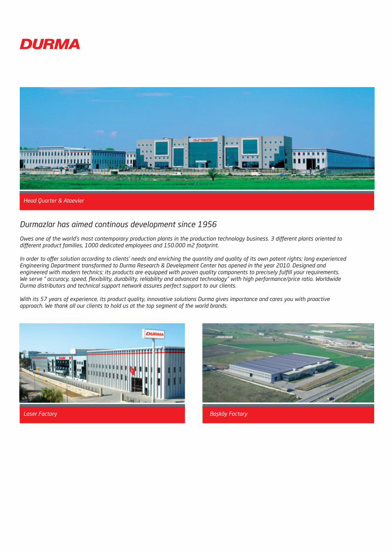
Durmazlar has aimed continous development since 1956
Owes one of the world’s most contemporary production plants in the production technology business. 3 different plants oriented todifferent product families, 1000 dedicated employees and 150.000 m2 footprint.
In order to offer solution according to clients’ needs and enriching the quantity and quality of its own patent rights; long experienced Engineering Department transformed to Durma Research & Develepment Center has opened in the year 2010. Designed andengineered with modern technics; its products are equipped with proven quality components to precisely fulfill your requirements.We serve “ accuracy, speed, flexibility, durability, reliability and advanced technology” with high performance/price ratio. Worldwide Durma distributors and technical support network assures perfect support to our clients.
With its 57 years of experience, its product quality, innovative solutions Durma gives importance and cares you with proactiveapproach. We thank all our clients to hold us at the top segment of the world brands.
Başköy FactoryLaser Factory
Head Quarter & Ataevler
2014_SUBAT_1.indd 2 11.06.2014 07:58

Durma Press Brakes
AD-R Series
Real Innovation
Value oriented press brakes with large strokes, daylights, and gaps to allow cost effective production of simple to complex large shaped that require large dimensions for handling and removal. A simple to use control reduces the required operator level.
AD-S Series
Superior
Unlimited possibilities and features providing faster and quicker setups and part production. Large daylight opening and working areas Outboard mounted long ram guides provide stabiity while allowing full length between the frame acute angle bendingStable and fast ac servo motor driven backgauge system3D Graphical Controller and Offline SoftwareAutomatic table crowningAutomatic sheet following systems
AD SERVO Series
Eco-friendly press brake for clean energy saving operations.Lower cost, Energy Efficient, Accurate ,Speed and Quiet .
FBS (Flexible Bending Solutions(
Durma’s advanced technology in the bending of large format parts has; for the auto-mated and reduced labor bending of large sheet and plate parts. diversifed uses in the different industries while avoiding long, expensive welding operations which even takes the risk of material stability.Reduced material handlingCompensation for high spring-back sheets Reduced setup times by automated loading and unloadingIncreasesed employee safteyOn higher tonnage press brakes Durma utililizes and unique “box construction” which provides the most stable machine frame in the industry. Durma provides the latest technology in “large format” bending and automation.
Durma press brakes guarantee precision, low maintenance costs, low operating cost, and longterm reliability . These features along with large investments in moldern manufacturing equipment have made Durma the largest volume press brake producer in the world.
All Durma press brakes are produced with modern design technology and incorporate rigid stress relieved frames to increase your produc-tivity with accurate part production. Demanding applications are easily achieved.
A broad offering of sizes and features satisfy nearly all economical requirements.
2014_SUBAT_1.indd 3 11.06.2014 07:58

AD-R SERIES
Real Innovation
Combination of Performance, Value and Simplicity
Best performance/price ratio CNC press brake of the world
Easy to use CNC controller
Specially designed control unit and software serve you simplicity and lean operations even for inexperienced
operators.
Perfect bending results , easy input the angle and operate the machine
Introduction to Durma Press Brakes
Robust construction,Same solid foundation of all Durma Press Brakes
Working with AD-R’s all range easy and comfortable in all respects.Large daylight opening and large space
enables the machine to be put to optimum use along its entire working length.
Designed and manufactured to meet the challange of “ Cost down” manufacturing culture
Provides standardly 3 axis Y1 Y2 X and R manually adjustable.
2014_SUBAT_1.indd 4 11.06.2014 07:58

FEATURES
AD-R machines offers wide spaces for ease of operation also reduces cycle times.
Double guides are long and accurate for easy sliding of top beam
Fingers` depth is calculated by CNC controller and executes X axis.Retraction is also a standard feature to acquire accurate parts. Back gauge fingers are easily adjusted on linear guides by ball integrated motion system.
Back GaugeX axis motorized CNC controlled R axis manually height adjustable finger block
Top beam guiding
Sliding Front Arms
Quickset support arms are mounted on a linear quide way and ball bearing system that allows “finger tip” lateral adjustment of the front support arms. Vertically adjustment is also easily achieved.
High Stroke - Daylight - Throat ( High working space
Top beam guiding
2014_SUBAT_1.indd 5 11.06.2014 07:58
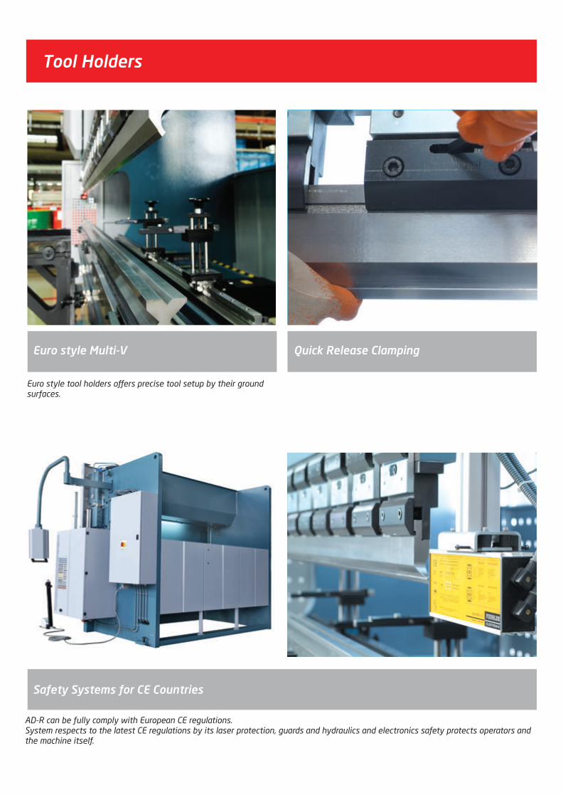
Tool Holders
Euro style tool holders offers precise tool setup by their ground surfaces.
AD-R can be fully comply with European CE regulations.System respects to the latest CE regulations by its laser protection, guards and hydraulics and electronics safety protects operators and the machine itself.
Safety Systems for CE Countries
Quick Release ClampingEuro style Multi-V
2014_SUBAT_1.indd 6 11.06.2014 07:58

2D graphic display (7,4”) & work piece in programming pageEasy bend functionAutomatic bending sequencePart calculationSafety guard PLC communicationOffline software (programming and edit features)Motorized crowningDiagnose of I/OUSB interface for backup and restore programs/tools/parametersMaintainence- free 85 programs (up to 12 steps each program); 12x85 = 1020 step32 Punches & DiesPrograms, Punches, Dies and Parameters can be copied using USB Disk orOff-Line softwareWide language optionsEasy upgrade possibility to color graphic control unit
Durma CNC Advantage
CNC Control Units
The DNC 880S numerical control is intended specifically for sheet-metal bending.According to the software installed, it will be used on synchronized or conventional press brakes with mechanical or hydraulic end stopsThe Dnc 880S is a high performance, competitively priced product in a compact andslim design10” TFT color screenGraphic 2D display and multi-simulation capabilityWindows XPe for multitasking and file management Connection to external devices through USB port for software updating and data backupOver 20 languages available
DNC 880s - CNC 2D
10” TFT colors touch screenAuto bending sequenceEasy bend function2D Graphic display and multi-simulation Linux operating systemOffline software availableTandem working Connection to external devices through USB port for software updating and data backup.Wide language optionsErgonomic panel design
Durma GT10 - Touch
2014_SUBAT_1.indd 7 11.06.2014 07:58

STANDARD EQUIPMENTS
Y1, Y2, X - 3 Axes
Control Unit - CNC Advantage
Back gauge - motorised & linear guide & ball bearing system
Back gauge fingers - height adjustable
European Clamping system
Sliding sheet support Arms with T-Canal and Tilting stop
CNC controlled motorized Crowning (only on 6meters)
Special designed - worldclass hydraulics blocks & valves
Worldclass electronics system
AD-R Series
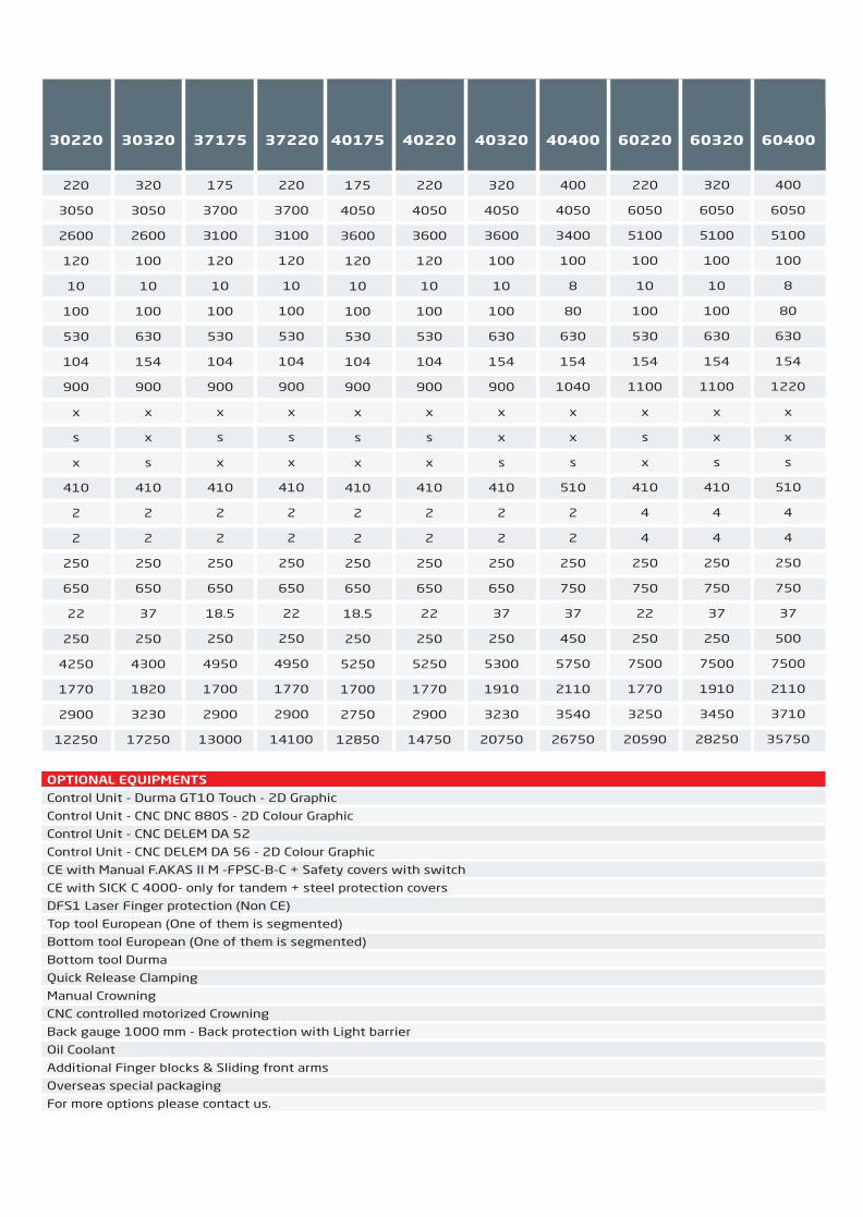
OPTIONAL EQUIPMENTS
Control Unit - Durma GT10 Touch - 2D Graphic
Control Unit - CNC DNC 880S - 2D Colour Graphic
Control Unit - CNC DELEM DA 52
Control Unit - CNC DELEM DA 56 - 2D Colour Graphic
CE with Manual F.AKAS II M -FPSC-B-C + Safety covers with switch
CE with SICK C 4000- only for tandem + steel protection covers
DFS1 Laser Finger protection (Non CE)
Top tool European (One of them is segmented)
Bottom tool European (One of them is segmented)
Bottom tool Durma
Quick Release Clamping
Manual Crowning
CNC controlled motorized Crowning
Back gauge 1000 mm - Back protection with Light barrier
Oil Coolant
Additional Finger blocks & Sliding front arms
Overseas special packaging
For more options please contact us.
Bending force
Bending length
Distance between columns
Y rapid speed
Y working speed
Y return speed
Crowning
Daylight
Table width
Table height
Depth of pit
Stroke
Throat depth
Support arms
Back gauge finger blocks2
Speed of travel in X-axisec
Travel in X-axis
Speed of R-axis(max.)
Travel in R-axis
Motor power
Oiltank capacity
Length
Width
Height
Weight approx.
AD-Servo Unit 30135 30175
(A)(B)
(D)(G)(F)
(F1)
ton
mm
mm
mm/sec
mm/sec
mm/sec
-
mm
mm
mm
mm
mm
mm
amount
amount
mm/sec
mm
mm/sec
mm
kw
lt
mm
mm
mm
kg
135
3050
2600
200
10
180
Motorized
530
104
900
x
265
410
2
2
500
650
350
250
4 x2
40 x 2
4200
1680
2850
10000
175
3050
2600
200
10
180
Motorized
530
104
900
x
265
410
2
2
500
650
350
250
5.5 x 2
50 x 2
4250
1700
2850
11500
(A)(B)
(D)(G)(F)
(F1)
AD-R Series Unit 1260 2060 25100 30100 30135 30175 30220 30320 37175 37220 40175 40220 40320 40400 60220 60320 60400
Bending force
Bending length
Distance between columns
Y Rapid speed
Y Working speed
Y Return speed
Daylight
Table width
Table height
Stroke 160
Stroke 265
Stroke 365
Throat depth
Support arms
Back gauge finger blocks
Speed of travel in X-axis
Travel in X-axis
Motor power
Oiltank capacity
Length
Width
Height
Weight approx
s: Standarto: Optionalx: Not Available
(A)
(B)
(D)
(G)
(F)
(C)
(C)
(C)
(E)
(L)
(W)
(H)
ton
mm
mm
mm/sec
mm/sec
mm/sec
mm
mm
mm
mm
mm
mm
mm
amount
amount
mm/sec
mm
kw
lt
mm
mm
mm
kg
60
1250
1050
200
10
110
400
104
900
s
o
x
350
2
2
250
750
7.5
100
2300
1200
2350
3100
60
2050
1700
200
10
110
400
104
900
s
o
x
350
2
2
250
650
7.5
100
3200
1200
2350
3550
100
2550
2200
180
10
120
530
104
900
x
s
x
410
2
2
250
650
11
100
3800
1670
2750
8650
100
3050
2600
180
10
120
530
104
900
x
s
x
410
2
2
250
650
11
100
4200
1670
2750
9250
135
3050
2600
160
10
120
530
104
900
x
s
x
410
2
2
250
650
15
150
4200
1680
2750
10250
175
3050
2600
120
10
100
530
104
900
x
s
x
410
2
2
250
650
18.5
250
4250
1700
2750
11250
220
3050
2600
120
10
100
530
104
900
x
s
x
410
2
2
250
650
22
250
4250
1770
2900
12250
320
3050
2600
100
10
100
630
154
900
x
x
s
410
2
2
250
650
37
250
4300
1820
3230
17250
175
3700
3100
120
10
100
530
104
900
x
s
x
410
2
2
250
650
18.5
250
4950
1700
2900
13000
220
3700
3100
120
10
100
530
104
900
x
s
x
410
2
2
250
650
22
250
4950
1770
2900
14100
175
4050
3600
120
10
100
530
104
900
265
410
2
2
500
650
18.5
250
5250
1700
2750
12850
220
4050
3600
120
10
100
530
104
900
265
410
2
2
500
650
22
250
5250
1770
2900
14750
320
4050
3600
100
10
100
630
154
900
365
410
2
2
500
650
37
250
5300
1910
3230
20750
400
4050
3400
100
8
80
630
154
1040
365
510
2
2
350
750
37
450
5750
2110
3540
26750
220
6050
5100
100
10
100
530
154
1100
265
410
4
4
350
750
22
250
7500
1770
3250
20590
320
6050
5100
100
10
100
630
154
1100
365
410
4
4
350
750
37
250
7500
1910
3450
28250
400
6050
5100
100
8
80
630
154
1220
365
510
4
4
350
750
37
500
7500
2110
3710
35750
40175 40220 40320 40400 60220 60320 60400
175
4050
3600
120
10
100
530
104
900
x
s
x
410
2
2
250
650
18.5
250
5250
1700
2750
12850
220
4050
3600
120
10
100
530
104
900
x
s
x
410
2
2
250
650
22
250
5250
1770
2900
14750
320
4050
3600
100
10
100
630
154
900
x
x
s
410
2
2
250
650
37
250
5300
1910
3230
20750
400
4050
3400
100
8
80
630
154
1040
x
x
s
510
2
2
250
750
37
450
5750
2110
3540
26750
220
6050
5100
100
10
100
530
154
1100
x
s
x
410
4
4
250
750
22
250
7500
1770
3250
20590
320
6050
5100
100
10
100
630
154
1100
x
x
s
410
4
4
250
750
37
250
7500
1910
3450
28250
400
6050
5100
100
8
80
630
154
1220
x
x
s
510
4
4
250
750
37
500
7500
2110
3710
35750
2014_SUBAT_1.indd 8 11.06.2014 07:58
STANDARD EQUIPMENTS
Y1, Y2, X - 3 Axes
Control Unit - CNC Advantage
Back gauge - motorised & linear guide & ball bearing system
Back gauge fingers - height adjustable
European Clamping system
Sliding sheet support Arms with T-Canal and Tilting stop
CNC controlled motorized Crowning (only on 6meters)
Special designed - worldclass hydraulics blocks & valves
Worldclass electronics system
AD-R Series
OPTIONAL EQUIPMENTS
Control Unit - Durma GT10 Touch - 2D Graphic
Control Unit - CNC DNC 880S - 2D Colour Graphic
Control Unit - CNC DELEM DA 52
Control Unit - CNC DELEM DA 56 - 2D Colour Graphic
CE with Manual F.AKAS II M -FPSC-B-C + Safety covers with switch
CE with SICK C 4000- only for tandem + steel protection covers
DFS1 Laser Finger protection (Non CE)
Top tool European (One of them is segmented)
Bottom tool European (One of them is segmented)
Bottom tool Durma
Quick Release Clamping
Manual Crowning
CNC controlled motorized Crowning
Back gauge 1000 mm - Back protection with Light barrier
Oil Coolant
Additional Finger blocks & Sliding front arms
Overseas special packaging
For more options please contact us.
Bending force
Bending length
Distance between columns
Y rapid speed
Y working speed
Y return speed
Crowning
Daylight
Table width
Table height
Depth of pit
Stroke
Throat depth
Support arms
Back gauge finger blocks2
Speed of travel in X-axisec
Travel in X-axis
Speed of R-axis(max.)
Travel in R-axis
Motor power
Oiltank capacity
Length
Width
Height
Weight approx.
AD-Servo Unit 30135 30175
(A)(B)
(D)(G)(F)
(F1)
ton
mm
mm
mm/sec
mm/sec
mm/sec
-
mm
mm
mm
mm
mm
mm
amount
amount
mm/sec
mm
mm/sec
mm
kw
lt
mm
mm
mm
kg
135
3050
2600
200
10
180
Motorized
530
104
900
x
265
410
2
2
500
650
350
250
4 x2
40 x 2
4200
1680
2850
10000
175
3050
2600
200
10
180
Motorized
530
104
900
x
265
410
2
2
500
650
350
250
5.5 x 2
50 x 2
4250
1700
2850
11500
(A)(B)
(D)(G)(F)
(F1)
AD-R Series Unit 1260 2060 25100 30100 30135 30175 30220 30320 37175 37220 40175 40220 40320 40400 60220 60320 60400
Bending force
Bending length
Distance between columns
Y Rapid speed
Y Working speed
Y Return speed
Daylight
Table width
Table height
Stroke 160
Stroke 265
Stroke 365
Throat depth
Support arms
Back gauge finger blocks
Speed of travel in X-axis
Travel in X-axis
Motor power
Oiltank capacity
Length
Width
Height
Weight approx
s: Standarto: Optionalx: Not Available
(A)
(B)
(D)
(G)
(F)
(C)
(C)
(C)
(E)
(L)
(W)
(H)
ton
mm
mm
mm/sec
mm/sec
mm/sec
mm
mm
mm
mm
mm
mm
mm
amount
amount
mm/sec
mm
kw
lt
mm
mm
mm
kg
60
1250
1050
200
10
110
400
104
900
s
o
x
350
2
2
250
750
7.5
100
2300
1200
2350
3100
60
2050
1700
200
10
110
400
104
900
s
o
x
350
2
2
250
650
7.5
100
3200
1200
2350
3550
100
2550
2200
180
10
120
530
104
900
x
s
x
410
2
2
250
650
11
100
3800
1670
2750
8650
100
3050
2600
180
10
120
530
104
900
x
s
x
410
2
2
250
650
11
100
4200
1670
2750
9250
135
3050
2600
160
10
120
530
104
900
x
s
x
410
2
2
250
650
15
150
4200
1680
2750
10250
175
3050
2600
120
10
100
530
104
900
x
s
x
410
2
2
250
650
18.5
250
4250
1700
2750
11250
220
3050
2600
120
10
100
530
104
900
x
s
x
410
2
2
250
650
22
250
4250
1770
2900
12250
320
3050
2600
100
10
100
630
154
900
x
x
s
410
2
2
250
650
37
250
4300
1820
3230
17250
175
3700
3100
120
10
100
530
104
900
x
s
x
410
2
2
250
650
18.5
250
4950
1700
2900
13000
220
3700
3100
120
10
100
530
104
900
x
s
x
410
2
2
250
650
22
250
4950
1770
2900
14100
175
4050
3600
120
10
100
530
104
900
265
410
2
2
500
650
18.5
250
5250
1700
2750
12850
220
4050
3600
120
10
100
530
104
900
265
410
2
2
500
650
22
250
5250
1770
2900
14750
320
4050
3600
100
10
100
630
154
900
365
410
2
2
500
650
37
250
5300
1910
3230
20750
400
4050
3400
100
8
80
630
154
1040
365
510
2
2
350
750
37
450
5750
2110
3540
26750
220
6050
5100
100
10
100
530
154
1100
265
410
4
4
350
750
22
250
7500
1770
3250
20590
320
6050
5100
100
10
100
630
154
1100
365
410
4
4
350
750
37
250
7500
1910
3450
28250
400
6050
5100
100
8
80
630
154
1220
365
510
4
4
350
750
37
500
7500
2110
3710
35750
40175 40220 40320 40400 60220 60320 60400
175
4050
3600
120
10
100
530
104
900
x
s
x
410
2
2
250
650
18.5
250
5250
1700
2750
12850
220
4050
3600
120
10
100
530
104
900
x
s
x
410
2
2
250
650
22
250
5250
1770
2900
14750
320
4050
3600
100
10
100
630
154
900
x
x
s
410
2
2
250
650
37
250
5300
1910
3230
20750
400
4050
3400
100
8
80
630
154
1040
x
x
s
510
2
2
250
750
37
450
5750
2110
3540
26750
220
6050
5100
100
10
100
530
154
1100
x
s
x
410
4
4
250
750
22
250
7500
1770
3250
20590
320
6050
5100
100
10
100
630
154
1100
x
x
s
410
4
4
250
750
37
250
7500
1910
3450
28250
400
6050
5100
100
8
80
630
154
1220
x
x
s
510
4
4
250
750
37
500
7500
2110
3710
35750
2014_SUBAT_1.indd 9 11.06.2014 07:58

AD-S SERIES
High end solution for bending
Represent the latest technology in press brake automation,
Well concieved design
Ultimate productivity when performing precision work
Large daylight opening and working space
The application of highly dynamic hydraulics servo valves
Long double guides in combination with well designed cylinder construction make a large an flexible beam opening possible.
Stable and fast AC Servo motor driven backgauge system
3D Graphical Controller & Offline Software
CNC Controlled crowning
Ensures maximum angle accuracy thus satisfying even the highest demands
Provides standardly 4 axis Y1 Y2 X and R
2014_SUBAT_1.indd 10 11.06.2014 07:58

Independent left and right axes (Y1Y2) controlled by electronics servo valves & electronics linear position controllers.
CNC controlled motorized crowning system homogenizes bend-ing forces every points of the bending parts to acquire straights bents. The need for shimming is eliminated.
Syncro Y1Y2 Axes & CNC Control Motorized Crowning
Quickset support arms are mounted on a linear quide way and ball bearing system that allows “finger tip” lateral adjustment of the front support arms. Vertically adjustment is also easily achieved.
Sliding Front Arms
FEATURES
Fingers` depth and height is calculated by CNC controller and executes high speed servo motors produced by Siemens.Retraction is also a standard feature to acquire accurate parts.Back gauge fingers are easily adjusted on linear guides by ball integrated motion system.
X-R Back Gauge
2014_SUBAT_1.indd 11 11.06.2014 07:58

CNC Control Units
Intuitive touch screen interfaceFull 3D simulationMultiple view points while workingMachine components can be individually made invisible for better job examination.Automatic or interactive solutions for bending sequences, gauging, corner gauging and tool mounting3D collision detection.User defined table for bend deduction.Rapid solution computation.Almost unlimited quantity of programs and sequences.Smooth and fast 3D motion.Windows XP Pro Compact for multitasking and file management.
ModEva RA - Standard(
The DA-66T is the Delem modular press brake controller. All graphics, including product and machine as well as tool setup are also available in 3D. This to visualize the machine situa-tion as accurate as possible. The DA-66T can program 2D products, accurately showing and calculating including sheet thickness and radii. During programming automatically generation of bend sequencers can be used as well as manual selection. The operator can overrule to his own choice. With the DA-66T also special tools for e.g. hemming bends can be programmed. The DA-66T helps the user in programming these bends (with their specific parameters) and also shows the prebend as well as the hemming operation during production.
Delem DA 66T
The DA-69T is 1:1 compatible with the DA-66T and offers next to 2D products also 3D products. 3D products can be programmed with accurate sheet thickness and desired radii. Automatical bend sequence calculation can help finding the optimum bendsequence even from very complex products. Multiple products can programmed in 3D, 2D as well as numeri-cal. Storage is managed on the CF-harddrive. The controllers Windows operating system enabled easy integration in factory networks and due to the real-time capable OS, also instant switch of is possible. The controller will start-up time after time, without annoying booting messages. The DA-66T and DA-69T can also be equipped with an optional touch screen.
Delem DA 69T
2014_SUBAT_1.indd 12 11.06.2014 07:58

AD-S can be fully comply with European CE regulations.System respects to the latest CE regulations by its laserprotection, guards and hydraulics and electronics safetyprotects operators and the machine itself.
Safety Systems for CE Countries
AD-S machines offers wide spaces for ease of operation also reduces cycle times.
High Stroke | Daylight | Throat= High working space
Eurostyle tool holders offers precise tool setup by their ground surfaces.
Tool Holders
Eurostyle Clamping
2014_SUBAT_1.indd 13 11.06.2014 07:58
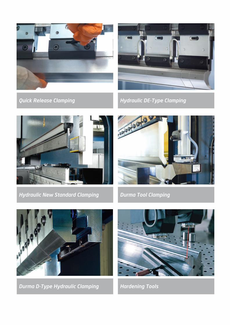
Hydraulic DE-Type ClampingQuick Release Clamping
Durma Tool ClampingHydraulic New Standard Clamping
Hardening ToolsDurma D-Type Hydraulic Clamping
2014_SUBAT_1.indd 14 11.06.2014 07:58

Back Gauge Options
Back Gauge Fingers
X1, X2, R, Z1, Z2 5 AxesX, R, Z1 Z2 4 Axes
Delta XX1, X2, R1, R2, Z1, Z2 6 Axes
Special Fingers3 Step Finger Blocks
2014_SUBAT_1.indd 15 11.06.2014 07:58

Motorized Positioning SystemPneumatic Positioning System
Bottom Tool Positioning Systems
Laser Angle Measurement System
Manufacturing sheet metal parts with properly bending angles that are kept constant all times often meets a problem during the actual production process: different parameters in material thickness and stresses. The best solution is laser based bending angle measuring device.
- Any bending angle can be measured.- Very compact, everything in the appliance.- Light influence, light or dark material surfaces play practically no part at all.
2014_SUBAT_1.indd 16 11.06.2014 07:58
AD-S Series
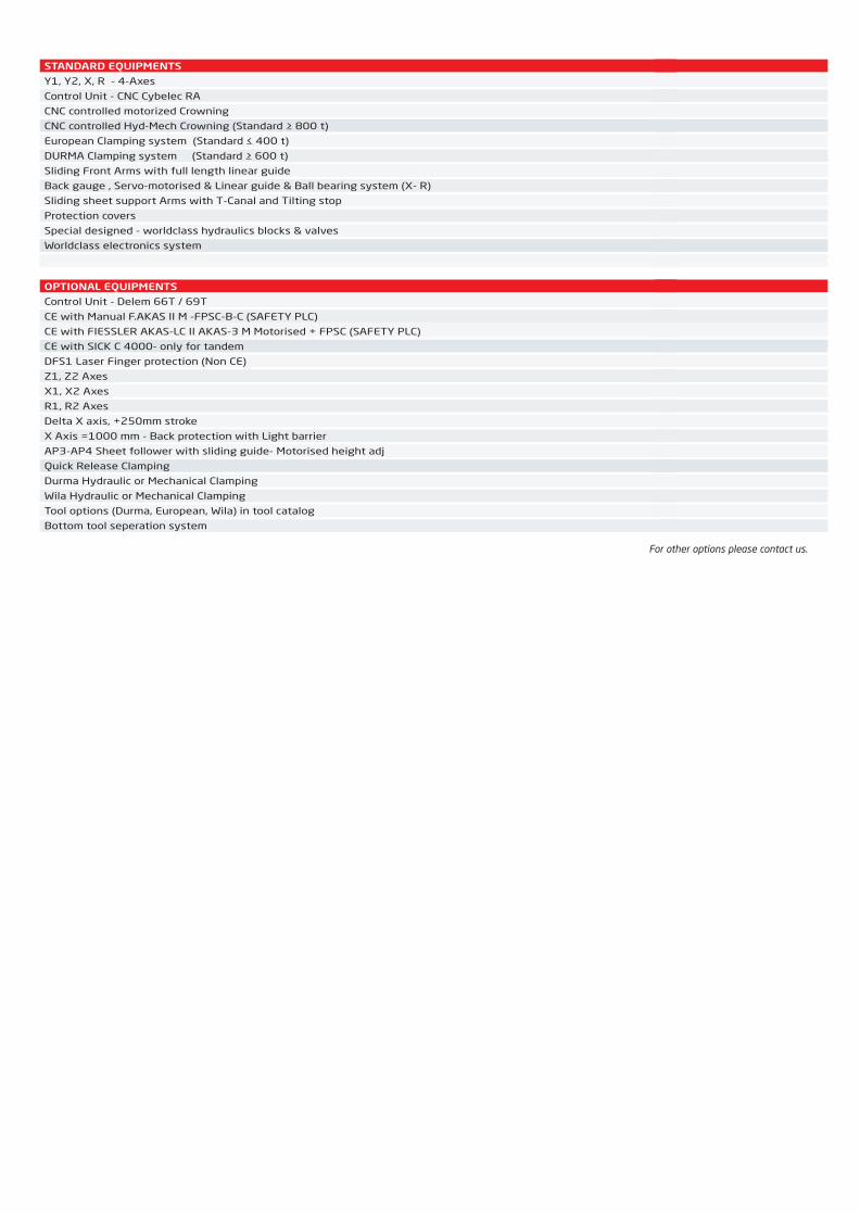
STANDARD EQUIPMENTS
Y1, Y2, X, R - 4-Axes
Control Unit - CNC Cybelec RA
CNC controlled motorized Crowning
CNC controlled Hyd-Mech Crowning (Standard ≥ 800 t)
European Clamping system (Standard ≤ 400 t)
DURMA Clamping system (Standard ≥ 600 t)
Sliding Front Arms with full length linear guide
Back gauge , Servo-motorised & Linear guide & Ball bearing system (X- R)
Sliding sheet support Arms with T-Canal and Tilting stop
Protection covers
Special designed - worldclass hydraulics blocks & valves
Worldclass electronics system
OPTIONAL EQUIPMENTS
Control Unit - Delem 66T / 69T
CE with Manual F.AKAS II M -FPSC-B-C (SAFETY PLC)
CE with FIESSLER AKAS-LC II AKAS-3 M Motorised + FPSC (SAFETY PLC)
CE with SICK C 4000- only for tandem
DFS1 Laser Finger protection (Non CE)
Z1, Z2 Axes
X1, X2 Axes
R1, R2 Axes
Delta X axis, +250mm stroke
X Axis =1000 mm - Back protection with Light barrier
AP3-AP4 Sheet follower with sliding guide- Motorised height adj
Quick Release Clamping
Durma Hydraulic or Mechanical Clamping
Wila Hydraulic or Mechanical Clamping
Tool options (Durma, European, Wila) in tool catalog
Bottom tool seperation system
AD-S Series
STANDARD EQUIPMENTS
Y1, Y2, X, R - 4-Axes
Control Unit - CNC Cybelec RA
CNC controlled motorized Crowning
CNC controlled Hyd-Mech Crowning (Standard ≥ 800 t)
European Clamping system (Standard ≤ 400 t)
DURMA Clamping system (Standard ≥ 600 t)
Sliding Front Arms with full length linear guide
Back gauge , Servo-motorised & Linear guide & Ball bearing system (X- R)
Sliding sheet support Arms with T-Canal and Tilting stop
Protection covers
Special designed - worldclass hydraulics blocks & valves
Worldclass electronics system
OPTIONAL EQUIPMENTS
Control Unit - Delem 66T / 69T
CE with Manual F.AKAS II M -FPSC-B-C (SAFETY PLC)
CE with FIESSLER AKAS-LC II AKAS-3 M Motorised + FPSC (SAFETY PLC)
CE with SICK C 4000- only for tandem
DFS1 Laser Finger protection (Non CE)
Z1, Z2 Axes
X1, X2 Axes
R1, R2 Axes
Delta X axis, +250mm stroke
X Axis =1000 mm - Back protection with Light barrier
AP3-AP4 Sheet follower with sliding guide- Motorised height adj
Quick Release Clamping
Durma Hydraulic or Mechanical Clamping
Wila Hydraulic or Mechanical Clamping
Tool options (Durma, European, Wila) in tool catalog
Bottom tool seperation system
For other options please contact us.
2014_SUBAT_1.indd 17 11.06.2014 07:58

AD-S Series Unit 1260 2060 25100 30100 30135 30175 30220 30320 37175 37220 40175 40220 40320 40400 60220 60320 60400
(A)
(B)
(D)
(G)
(F)
(F1)
(C)
(C)
(C)
(C)
(C)
(C)
(E)
(L)
(W)
(H)
ton
mm
mm
mm/sec
mm/sec
mm/sec
-
mm
mm
mm
mm
mm
mm
mm
mm
mm
mm
mm
amount
amount
mm/sec
mm
mm/sec
mm
kw
lt
mm
mm
mm
kg
60
1250
1050
200
10
110
Mot.
530
104
900
-
s
s
x
x
x
x
350
2
2
500
750
350
250
7.5
100
2300
1200
2350
3100
60
2050
1700
200
10
110
Mot.
530
104
900
-
s
s
x
x
x
x
410
2
2
500
650
350
250
7.5
100
3200
1200
2350
3550
100
2550
2200
180
10
120
Mot.
530
104
900
-
x
s
x
x
x
x
410
2
2
500
650
350
250
11
100
3800
1670
2750
8900
100
3050
2600
180
10
120
Mot.
530
104
900
-
x
s
x
x
x
x
410
2
2
500
650
350
250
11
100
4200
1670
2750
9500
135
3050
2600
160
10
120
Mot.
530
104
900
-
x
s
x
x
x
x
410
2
2
500
650
350
250
15
150
4200
1680
2750
10500
175
3050
2600
120
10
100
Mot.
530
104
900
-
x
s
x
x
x
x
410
2
2
500
650
350
250
18.5
250
4250
1700
2750
11500
220
3050
2600
120
10
100
Mot.
530
154
900
-
x
s
x
x
x
x
410
2
2
500
650
350
250
22
250
4250
1770
2900
12500
320
3050
2600
100
10
100
Mot.
630
104
900
-
x
s
x
x
x
x
410
2
2
500
650
350
250
37
250
4300
1820
3230
17500
175
3700
3100
120
10
100
Mot.
530
104
900
-
x
s
x
x
x
x
410
2
2
500
650
350
250
18.5
250
4950
1700
2900
13000
220
3700
3100
120
10
100
Mot.
530
104
900
-
x
s
x
x
x
x
410
2
2
500
650
350
250
22
250
4950
1770
2900
14360
175
4050
3600
120
10
100
Mot.
530
104
900
-
x
s
x
x
x
x
410
2
2
500
650
350
250
18.5
250
5250
1700
2750
13100t
220
4050
3600
120
10
100
Mot.
530
104
900
-
x
s
x
x
x
x
410
2
2
500
650
350
250
22
250
5250
1770
2900
15000
320
4050
3600
100
10
100
Mot.
630
154
900
-
x
x
s
x
x
x
410
2
2
500
650
350
250
37
250
5300
1910
3230
21000
400
4050
3400
100
8
80
Mot.
630
300
1040
-
x
x
s
o
o
o
510
2
2
350
750
300
250
37
450
5750
2110
3540
27000
220
6050
5100
80
10
100
Mot.
530
154
1100
-
x
s
o
o
o
o
410
4
4
350
750
300
250
22
250
7500
1770
3250
20840
320
6050
5100
100
10
100
Mot.
630
154
1100
-
x
x
s
o
o
o
410
4
4
350
750
300
250
37
250
7500
1910
3450
28500
400
6050
5100
100
8
80
Mot.
630
300
1220
-
x
x
s
o
o
o
510
4
4
350
750
300
250
37
500
7500
2110
3710
36000
Bending force
Bending length
Distance between columns
Y rapid speed
Y working speed
Y return speed
Crowning
Daylight
Table width
Table height
Depth of pit
Stroke 160
Stroke 265
Stroke 365
Stroke 400
Stroke 500
Stroke 600
Throat depth
Support arms
Back gauge finger blocks
Speed of travel in X-axis
Travel in X-axis
Speed of R-axis(max.)
Travel in R-axis
Motor power
Oiltank capacity
Length
Width
Height
Weight approx
s: Standarto: Optionalx: Not Available
60600 60800 70800 701000 701250 80800 801000 801250 801600 802000 40600
600
6050
5100
80
7
80
Mot.
700
300
990
1200
x
x
s
o
o
o
510
4
4
350
750
300
250
45
500
7600
2650
3850
54000
800
6050
5100
70
6
80
Hyd-Mech
700
400
800
1300
x
x
x
s
o
o
610
4
4
350
750
300
250
55
750
8050
3200
4250
72000
800
7050
5100
80
7
70
Hyd-Mech
700
400
800
1300
x
x
x
s
o
o
610
4
4
350
750
300
250
55
750
8700
3200
4250
79500
1000
7050
5100
70
5
60
Hyd-Mech
800
400
800
1500
x
x
x
x
s
o
610
4
4
300
1000
250
250
55
1000
8800
3250
5900
95500
1250
7050
5100
70
7
70
Hyd-Mech
800
400
900
1700
x
x
x
x
x
s
610
4
4
300
1000
250
250
90
1250
8800
3250
6400
110000
800
8050
6400
80
7
70
Hyd-Mech
700
400
800
1300
x
x
x
s
o
o
610
4
6
300
750
300
250
55
750
9800
3200
4250
85000
1000
8050
6400
70
5
60
Hyd-Mech
800
400
800
1600
x
x
x
x
s
o
610
4
6
300
1000
250
250
55
1000
10000
3250
5900
102000
1250
8050
6400
70
7
70
Hyd-Mech
800
500
900
1800
x
x
x
x
s
o
610
4
6
300
1000
250
250
90
1250
10000
3250
6400
135000
1600
8100
6400
70
6
70
Hyd-Mech
1000
500
900
1800
x
x
x
s
o
o
610
4
6
300
1000
250
250
90
1250
10100
3500
7000
163000
2000
8100
6400
70
6
60
Hyd-Mech
1000
700
950
2100
x
x
x
x
x
s
750
4
6
300
1250
250
250
110
2000
10500
4350
8100
249000
600
4050
3100
80
7
80
Mot.
700
300
990
1200
x
x
s
o
o
o
510
2
2
350
750
300
250
45
500
5650
3250
3825
40500
2014_SUBAT_1.indd 18 11.06.2014 07:58

AD-S Series Unit 1260 2060 25100 30100 30135 30175 30220 30320 37175 37220 40175 40220 40320 40400 60220 60320 60400
(A)
(B)
(D)
(G)
(F)
(F1)
(C)
(C)
(C)
(C)
(C)
(C)
(E)
(L)
(W)
(H)
ton
mm
mm
mm/sec
mm/sec
mm/sec
-
mm
mm
mm
mm
mm
mm
mm
mm
mm
mm
mm
amount
amount
mm/sec
mm
mm/sec
mm
kw
lt
mm
mm
mm
kg
60
1250
1050
200
10
110
Mot.
530
104
900
-
s
s
x
x
x
x
350
2
2
500
750
350
250
7.5
100
2300
1200
2350
3100
60
2050
1700
200
10
110
Mot.
530
104
900
-
s
s
x
x
x
x
410
2
2
500
650
350
250
7.5
100
3200
1200
2350
3550
100
2550
2200
180
10
120
Mot.
530
104
900
-
x
s
x
x
x
x
410
2
2
500
650
350
250
11
100
3800
1670
2750
8900
100
3050
2600
180
10
120
Mot.
530
104
900
-
x
s
x
x
x
x
410
2
2
500
650
350
250
11
100
4200
1670
2750
9500
135
3050
2600
160
10
120
Mot.
530
104
900
-
x
s
x
x
x
x
410
2
2
500
650
350
250
15
150
4200
1680
2750
10500
175
3050
2600
120
10
100
Mot.
530
104
900
-
x
s
x
x
x
x
410
2
2
500
650
350
250
18.5
250
4250
1700
2750
11500
220
3050
2600
120
10
100
Mot.
530
154
900
-
x
s
x
x
x
x
410
2
2
500
650
350
250
22
250
4250
1770
2900
12500
320
3050
2600
100
10
100
Mot.
630
104
900
-
x
s
x
x
x
x
410
2
2
500
650
350
250
37
250
4300
1820
3230
17500
175
3700
3100
120
10
100
Mot.
530
104
900
-
x
s
x
x
x
x
410
2
2
500
650
350
250
18.5
250
4950
1700
2900
13000
220
3700
3100
120
10
100
Mot.
530
104
900
-
x
s
x
x
x
x
410
2
2
500
650
350
250
22
250
4950
1770
2900
14360
175
4050
3600
120
10
100
Mot.
530
104
900
-
x
s
x
x
x
x
410
2
2
500
650
350
250
18.5
250
5250
1700
2750
13100t
220
4050
3600
120
10
100
Mot.
530
104
900
-
x
s
x
x
x
x
410
2
2
500
650
350
250
22
250
5250
1770
2900
15000
320
4050
3600
100
10
100
Mot.
630
154
900
-
x
x
s
x
x
x
410
2
2
500
650
350
250
37
250
5300
1910
3230
21000
400
4050
3400
100
8
80
Mot.
630
300
1040
-
x
x
s
o
o
o
510
2
2
350
750
300
250
37
450
5750
2110
3540
27000
220
6050
5100
80
10
100
Mot.
530
154
1100
-
x
s
o
o
o
o
410
4
4
350
750
300
250
22
250
7500
1770
3250
20840
320
6050
5100
100
10
100
Mot.
630
154
1100
-
x
x
s
o
o
o
410
4
4
350
750
300
250
37
250
7500
1910
3450
28500
400
6050
5100
100
8
80
Mot.
630
300
1220
-
x
x
s
o
o
o
510
4
4
350
750
300
250
37
500
7500
2110
3710
36000
Bending force
Bending length
Distance between columns
Y rapid speed
Y working speed
Y return speed
Crowning
Daylight
Table width
Table height
Depth of pit
Stroke 160
Stroke 265
Stroke 365
Stroke 400
Stroke 500
Stroke 600
Throat depth
Support arms
Back gauge finger blocks
Speed of travel in X-axis
Travel in X-axis
Speed of R-axis(max.)
Travel in R-axis
Motor power
Oiltank capacity
Length
Width
Height
Weight approx
s: Standarto: Optionalx: Not Available
60600 60800 70800 701000 701250 80800 801000 801250 801600 802000 40600
600
6050
5100
80
7
80
Mot.
700
300
990
1200
x
x
s
o
o
o
510
4
4
350
750
300
250
45
500
7600
2650
3850
54000
800
6050
5100
70
6
80
Hyd-Mech
700
400
800
1300
x
x
x
s
o
o
610
4
4
350
750
300
250
55
750
8050
3200
4250
72000
800
7050
5100
80
7
70
Hyd-Mech
700
400
800
1300
x
x
x
s
o
o
610
4
4
350
750
300
250
55
750
8700
3200
4250
79500
1000
7050
5100
70
5
60
Hyd-Mech
800
400
800
1500
x
x
x
x
s
o
610
4
4
300
1000
250
250
55
1000
8800
3250
5900
95500
1250
7050
5100
70
7
70
Hyd-Mech
800
400
900
1700
x
x
x
x
x
s
610
4
4
300
1000
250
250
90
1250
8800
3250
6400
110000
800
8050
6400
80
7
70
Hyd-Mech
700
400
800
1300
x
x
x
s
o
o
610
4
6
300
750
300
250
55
750
9800
3200
4250
85000
1000
8050
6400
70
5
60
Hyd-Mech
800
400
800
1600
x
x
x
x
s
o
610
4
6
300
1000
250
250
55
1000
10000
3250
5900
102000
1250
8050
6400
70
7
70
Hyd-Mech
800
500
900
1800
x
x
x
x
s
o
610
4
6
300
1000
250
250
90
1250
10000
3250
6400
135000
1600
8100
6400
70
6
70
Hyd-Mech
1000
500
900
1800
x
x
x
s
o
o
610
4
6
300
1000
250
250
90
1250
10100
3500
7000
163000
2000
8100
6400
70
6
60
Hyd-Mech
1000
700
950
2100
x
x
x
x
x
s
750
4
6
300
1250
250
250
110
2000
10500
4350
8100
249000
600
4050
3100
80
7
80
Mot.
700
300
990
1200
x
x
s
o
o
o
510
2
2
350
750
300
250
45
500
5650
3250
3825
40500
For other sizes please contact us.
2014_SUBAT_1.indd 19 11.06.2014 07:58

Increase your competitive forces by %62 lower power consumption
Lower cost per part by ecologic technology
Quiet, Energy Efficient and Accurate
Ram movement is powered by AC Servo motors driving hydraulic oil in line with Variable Speed Pump.
New technology allows :
Silent bends,
Noise level reduced to 63 dbA from 76 dbA
Energy save,
62% at stand-by
44% during the press cycle
60 % in 1 hour with 15 press cycles
Supports your production cost efficiency and increases your competitive forces.
Small hydraulic oil tank for Clean environment & Cost reduction
Thanks to the new technology reduce hydraulic tank from 200 lt to 2x40 lt
Speeds & Accuracy & Syncronisation
Beam speeds to 200mm/sec
5,6 times better Synchronisation in phase of „High Speed“
AD-SERVO
2014_SUBAT_1.indd 20 11.06.2014 07:58

AD-Servo Unit 30135 30175
(A)
(B)
(D)
(G)
(F)
(F1)
(C)
(E)
(L)
(W)
(H)
ton
mm
mm
mm/sec
mm/sec
mm/sec
-
mm
mm
mm
mm
mm
mm
amount
amount
mm/sec
mm
mm/sec
mm
kw
lt
mm
mm
mm
kg
135
3050
2600
200
10
180
Motorized
530
104
900
-
265
410
2
2
500
650
350
250
2x4
80
4200
1680
2750
10500
175
3050
2600
180
10
160
Motorized
530
104
900
-
265
410
2
2
500
650
350
250
2x30
120
4250
1700
2750
11500
25100 30100
100
2550
2200
200
10
200
Motorised
530
104
900
-
265
410
2
2
500
650
350
250
2x4
80
3800
1670
2750
8900
100
3050
2600
200
10
200
Motorized
530
104
900
-
265
410
2
2
250
650
350
250
2x4
80
4200
1670
2750
9500
Bending force
Bending length
Distance between columns
Y rapid speed
Y working speed
Y return speed
Crowning
Daylight
Table width
Table height
Depth of pit������������������������������������
Stroke
Throat depth
Support arms
Back gauge finger blocks
Speed of travel in X-axis
Travel in X-axis
Speed of R-axis(max.)
Travel in R-axis
Motor power
Oiltank capacity
Length
Width
Height
Weight approx.AD-S Series
STANDARD EQUIPMENTS
Y1, Y2, X, R - 4-Axes
Control Unit - CNC Cybelec RA
CNC controlled motorized Crowning
CNC controlled Hyd-Mech Crowning (Standard ≥ 800 t)
European Clamping system (Standard ≤ 400 t)
DURMA Clamping system (Standard ≥ 600 t)
Sliding Front Arms with full length linear guide
Back gauge , Servo-motorised & Linear guide & Ball bearing system (X- R)
Sliding sheet support Arms with T-Canal and Tilting stop
Protection covers
Special designed - worldclass hydraulics blocks & valves
Worldclass electronics system
OPTIONAL EQUIPMENTS
Control Unit - Delem 66T / 69T
CE with Manual F.AKAS II M -FPSC-B-C (SAFETY PLC)
CE with FIESSLER AKAS-LC II AKAS-3 M Motorised + FPSC (SAFETY PLC)
CE with SICK C 4000- only for tandem
DFS1 Laser Finger protection (Non CE)
Z1, Z2 Axes
X1, X2 Axes
R1, R2 Axes
Delta X axis, +250mm stroke
X Axis =1000 mm - Back protection with Light barrier
AP3-AP4 Sheet follower with sliding guide- Motorised height adj
Quick Release Clamping
Durma Hydraulic or Mechanical Clamping
Wila Hydraulic or Mechanical Clamping
Tool options (Durma, European, Wila) in tool catalog
Bottom tool seperation system
For other options please contact us.
2014_SUBAT_1.indd 21 11.06.2014 07:58

FBS
Advanced Technologies for bending large sheet metal for extremely diversifed uses in the different industries while
avoiding long, expensive welding operations which even takes the risk of material stability.
FBS focuses also to minimize the large workpieces’ handling before, during and after the bending operations and
respects the next process.By this way offers:
Flexibility of bending varies for diversified uses
Accuracy for large & high spring-back sheets
Lowers setup times by automation of loading& unloading
Increases your employees’ safety
On high tonnage mega press brakes “box construction” frame is used which is the most stabile machine body in the
world utilised technology for press brakes.Stability and rigidity of box constructions is approved by our refences all
around the world and finite element analysis on the computers.
Durma can provide you with all the support Flexible Bending Solutions and offer to the turnkey automatic bending
cells complete with facility for loading and unloading.
(Flexible Bending Solutions)
2014_SUBAT_1.indd 22 11.06.2014 07:59

CUSTOM MADE PROJECTS
Loading Unloading SystemFront Feeding System with Pneumatic PushersLight Pole Industry – Unmanned Production
AD-S Tandem 812000
Loading Unloading SystemFront Feeding System with Pneumatic PushersLight Pole Industry – Unmanned Production
AD-S Tandem 911000
2014_SUBAT_1.indd 23 11.06.2014 07:59

AD-S Tandem 60400
System 1 From Side System 2 From Bottom
Motorised Front Feeding SystemLight Pole Industry
AD-S 80800 & 40400Truck Dumper Industry
2014_SUBAT_1.indd 24 11.06.2014 07:59

AD-S 802000Defence Industry
AD-S 1051500Special Hydraulics Front Support SystemSteel Service Industry
2014_SUBAT_1.indd 25 11.06.2014 07:59

AD-S Trio 40400Steel Service Industry
AD-S Tandem 45220AP3 AP4 Sheet Followers
2014_SUBAT_1.indd 26 11.06.2014 07:59
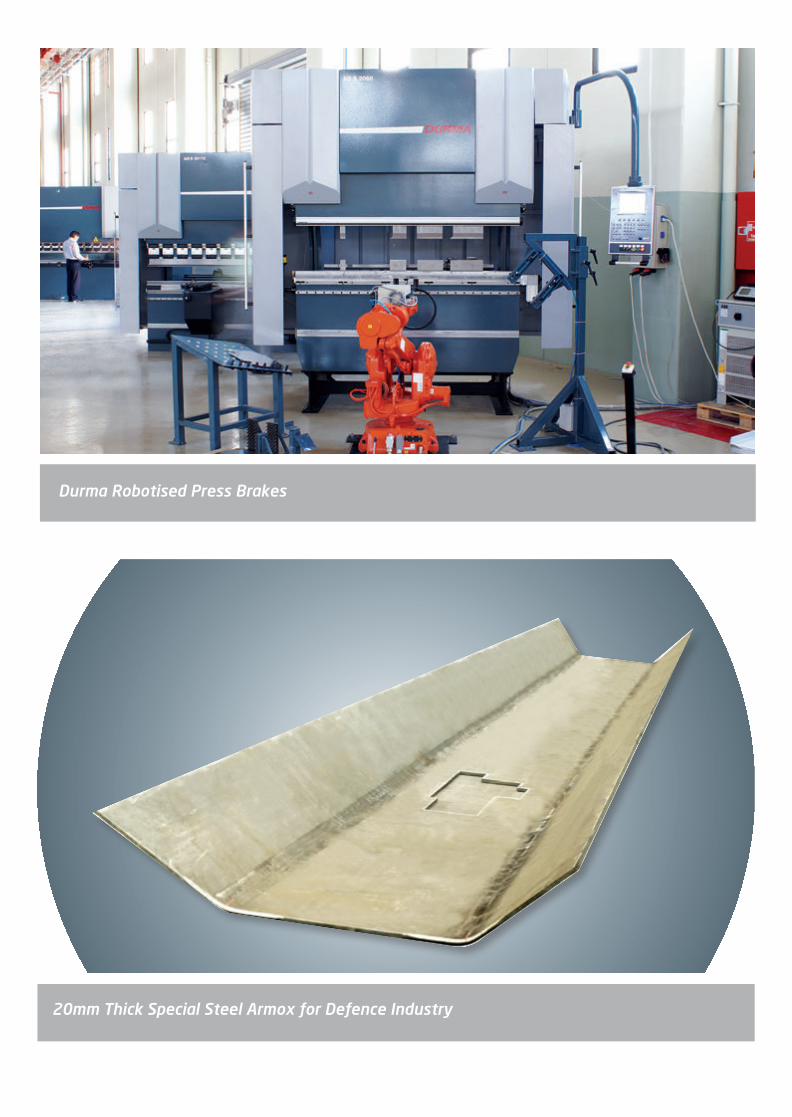
20mm Thick Special Steel Armox for Defence Industry
Durma Robotised Press Brakes
2014_SUBAT_1.indd 27 11.06.2014 07:59

Special Hydraulics Front Support System Road Barriers Industry
FEATURES
We have 3 solutions for light pole pull out.
Light Pole Pull-Out Systems
System 1 From Side System 2 From Bottom
2014_SUBAT_1.indd 28 11.06.2014 07:59
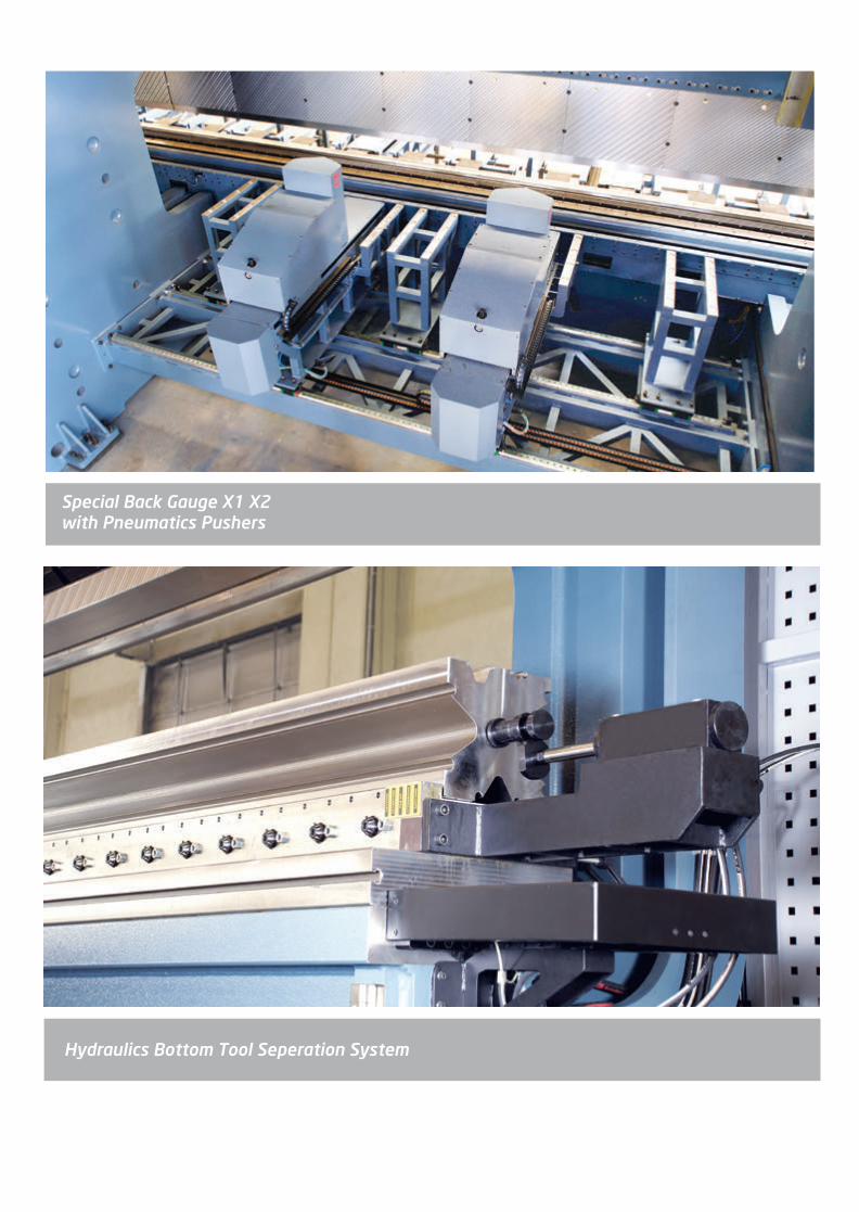
Hydraulics Bottom Tool Seperation System
Special Back Gauge X1 X2 with Pneumatics Pushers
2014_SUBAT_1.indd 29 11.06.2014 07:59

Bottom Tool Lamel Adjustable System
Bottom Tool Adjustable Systems
Bottom Tool Manual Adjustable SystemBottom Tool Motorised Adjustable System
2014_SUBAT_1.indd 30 11.06.2014 07:59
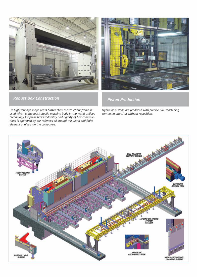
On high tonnage mega press brakes “box construction” frame is used which is the most stabile machine body in the world utilised technology for press brakes.Stability and rigidity of box construc-tions is approved by our refences all around the world and finite element analysis on the computers.
Robust Box Construction
Hydraulic pistons are produced with precise CNC machining centers in one shot without reposition.
Piston Production
2014_SUBAT_1.indd 31 11.06.2014 07:59

Cnc precise processing applied for all frames at one time without repositioning for tandem, trio and tetra press brakes.
Frame Machining Tandem - Trio ( Tetra Press Brakes
AD-S 801000 Top Beam Machining
2014_SUBAT_1.indd 32 11.06.2014 07:59

Durma Shears
VS Series
Variable Rake CNC Shear
Cutting angle and blade gap Automatically CNC adjusted for flexible and precise cutting processes
SBT Series
Swing Beam Touch Shear
Heavy duty, robust swing beam cutting for optimised cutting parameters
MS Series
Power Operated Shear
All-in: Hi-Speed, Accurate, Efficient, Performance
Durma shears have been manufactured since 1956 and are installed and working in a wide variety of sheet metal cutting operations for many industries. Years of customer application experience has helped us develop durable, low distortion and precise cutting machines.
Even large shears are machine frames are machined with our respositioning on the maching centers. Resulting in parallel and square services.
Automatic adjustment of the holddown pressure in our hydraulic shears firmly secures thick or thin sheet prior to the actual cutting.
2014_SUBAT_1.indd 33 11.06.2014 07:59

VS SERIES
Variable Rake CNC Shear
Solid design & durable body for precise cutting results
Blade clearance and cutting angle automatically adjusted by CNC controller
Userfriendly CNC Touchscreen control unit
Flexibility for thin or thick, narrow or wide sheets
For more sophisticated usage ; automatic swing-up back gauge, sheet support systems, return to
sender, automatic feeding and conveyor systems are easily integrated
For sheet handling and ease of operations ; standard t-slotted sheet support arms and tabetop
ball transfers easy feeding of the sheet
Fast cycle times for thick or thin sheets
2014_SUBAT_1.indd 34 11.06.2014 07:59

VS Series Features
The backguage adjustment, standart range 1000 mm, has play free straight guides and re-circulating ball spindles; it has speed of 200 mm/sec, a setting accuracy of 0,1 mm and a repetitive accuracy of +/-0,1 mm (by means of a closed loop control). A standard feature of the backgague is clearance compensation and it retracts automatically when cutting narrow strips. Back gauge can swing away at the end of its travel to allow the shearing of unlimited length drop pieces.
Throat Depth
Back Gauge
The first one meter of the finger guard can be flipped up out of the way for easy viewing of the work piece at the point of cut. Holddowns are provided to ensure that the plate is held firmly along the length of the cutting area. The holddowns are distrib-uted in such a way that more are closer at each end of the table. This guarantees not only safer operation at the beginning and end of the cut but also the accuracy for narrow (short) plates at each end of the machine. Each independently acting holddown is capable of applying high pressure to hold the material being cut at the same time preventing thin and delicate materials from being marked.
Finger Guard, Ball Transfers & Holddowns
Simple, secure handling
Light Curtain fo finger protection
Throat Depth (minimum 350 mm) in the side frames allow shear-ing of sheets longer than the blade length.
2014_SUBAT_1.indd 35 11.06.2014 07:59

CNC Control Units
Large Color Touch Screen, Lcd: 7”, 800 X 480 Tft Lcd DisplayRapid data inputAutomatic blade gapAutomatic cutting angleAutomatic cutting lengthEasy communication, USB Port: Usb port for user usb flash memoryEthernet: RJ-45 10/100M Operating System: Windows CE User Program and Steps: Unlimited Material Type: Unlimited
D-Touch 7
2014_SUBAT_1.indd 36 11.06.2014 07:59

Durma 3
POSITION 1
POSITION 2
POSITION 3
HH3 - PNEUMATIC THIN SHEET SUPPORT SYSTEMVS MACHINE
2.CONDITION ( ANTI-TWISTING )
POSITION 1 - 3
POSITION 2
HH3 - PNEUMATIC THIN SHEET SUPPORT SYSTEMVS MACHINE
3.CONDITION ( RETURN TO SENDER )
POSITION 4
Anti twisting Return to sender
POSITION 1
( UNLOADING MOVEMENT )
HH1 - PNEUMATIC THIN SHEET SUPPORT SYSTEMSB - VS MACHINE
POSITION 2
Durma 1
Durma 4
2014_SUBAT_1.indd 37 11.06.2014 08:00
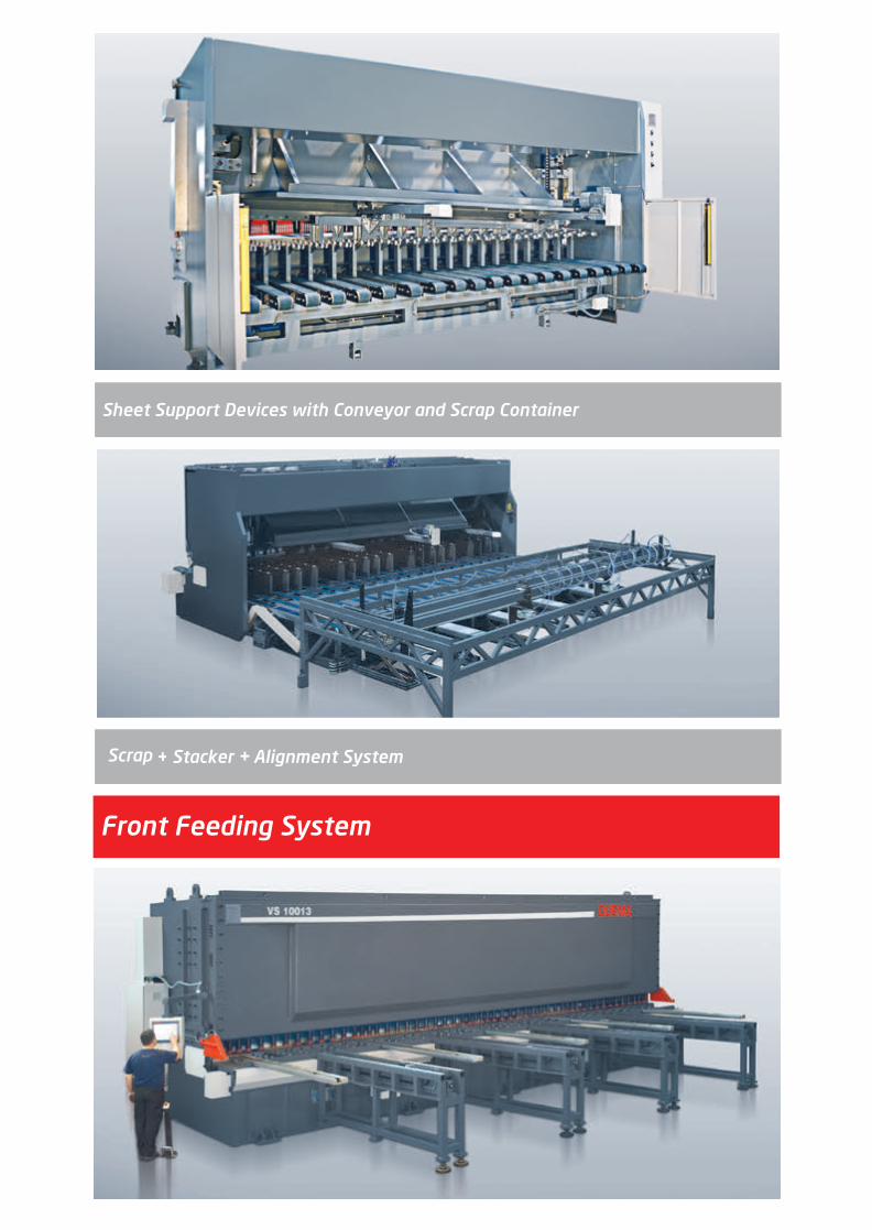
Sheet Support Devices with Conveyor and Scrap Container
Front Feeding System
2014_SUBAT_1.indd 38 11.06.2014 08:00

VS
OPTIONAL EQUIPMENTS
DNC 61 Control Unit
Laser Cutting Line
Light Curtains for Finger Protection
Pneumatic sheet support device standart - Durma I
Pneumatic sheet support device with return to sender - Durma III
Pneumatic sheet support device Durma IV
Sheet Support device with conveyor belt and scrap container
Stacker + Aligment Cylinder
CNC Front Feeding System
Hydraulic anti-twist device
Special Throat Depth
Backgauge 1250 mm
X1, X2 Axis
Hydraulic swing-up back gauge
Adjustable holddown pressure
Oil Coolant
Central lubrıcation manual
Central lubrıcation motorised
Adjustable Angle stop 0-180°
Add. Support Arms
Special blades
Special color
Control Panel on opposite position
Temperature measurement
Overseas special packaging
STANDARD EQUIPMENTS
Heavy duty St 44 steel construction & Stress relieved frame
Userfriendly CNC Touchscreen control unit - D-Touch 7
Automatically adjusted rake angle by CNC
Automatically adjusted blade gap by CNC
Automatically adjusted cutting length by CNC
Ball integrated front tables
Ballscrew back gauge, 1000 mm
1 mt flip-up finger guards
Squaring arm with scale & T-Slot & Tilting stop ( L= 1500 mm )
Support arms T-Slot & Tilting stop ( L=1000 mm )
Illumination & Shadow line
Throat depth with 350 mm
Automatically pressure adjusted solid holddowns
Top and Bottom blades with 4 sides
Foot pedal
High performance hydraulics & electronics components
CE-Norm for EU
2014_SUBAT_1.indd 39 11.06.2014 08:00

VS Series
(A)
(D)
(C)
(B)
(R)
(L)
(W1)
(W)
(H)
Unit
mm
mm
mm
Min 1/min
Max 1/min
Min 1/min
Max 1/min
Degree
Degree
Units
Min-ton
Max-ton
min
mm/sec
kW
It
mm
Units
mm
mm
mm
mm
mm
mm
mm
~kg
3006 3010 3013 3016 3020 4006 4013 4016
3080
6
4
12
20
21
33
0˚30’
2˚
16
4
20
1000
200
11
125
350
3
820
494
3280
4100
2050
3650
1950
7500
3080
10
7.5
10
20
15
27
0°30'
2°
16
4
20
1000
200
22
180
350
3
820
554
3360
3800
2050
3550
2150
9300
3080
13
10
9
17
15
27
0°30'
2°30'
17
8
40
1000
200
30
300
350
3
835
559
3380
4200
2100
3560
2450
12900
3080
16
12
7
12
11
18
0°30'
2°30'
14
11
55
1000
200
45
450
350
3
840
554
3420
4130
2210
3820
2570
18000
3080
20
15.5
6
12
9
17
0°30'
2°30'
14
17
83
1000
200
45
500
350
3
840
580
3460
4100
2300
3700
2650
21500
4080
6
4
10
20
19
31
0°30'
2°
20
4
20
1000
200
11
125
350
4
820
494
4400
5150
2100
3550
2050
12000
4080
13
10
7
13
13
25
0°30'
2°30'
20
10
48
1000
200
30
330
350
4
835
589
4400
5200
2150
3560
2550
16500
4080
16
15
9
10
0°30'
2°30'
20
17
50
1000
200
45
400
350
4
1000
630
4385
5890
2100
3625
2950
23600
Cutting Capacity
Cutting Angle
Holddown Force
Stroke per min.
HI Speed Stroke /min.
MS (450 N/mm²)
SS (700 N/mm²)
Min
Max
Cutting Length
Number of Holddowns
Backgauge course
Backgauge speed
Motor Power
Oil Capacity
Throat Depth
Front Arms
Table Height
Table Width
Table Length
Length
Width
Total Width
Height
Weight
VS Series
(A)
(D)
(C)
(B)
(R)
(L)
(W1)
(W)
(H)
Unit
mm
mm
mm
Min 1/min
Max 1/min
Min 1/min
Max 1/min
Degree
Degree
Units
Min-ton
Max-ton
min
mm/sec
kW
It
mm
Units
mm
mm
mm
mm
mm
mm
mm
~kg
3006 3010 3013 3016 3020 4006 4013 4016
3080
6
4
12
20
21
33
0˚30’
2˚
16
4
20
1000
120
11
125
350
3
820
494
3280
4100
2050
3650
1950
7500
3080
10
7.5
10
20
15
27
0°30'
2°
16
4
20
1000
120
22
180
350
3
820
554
3360
3800
2050
3550
2150
9300
3080
13
10
9
17
15
27
0°30'
2°30'
17
8
40
1000
120
30
300
350
3
835
559
3380
4200
2100
3560
2450
12900
3080
16
12
7
12
11
18
0°30'
2°30'
14
11
55
1000
120
45
450
350
3
840
554
3420
4130
2210
3820
2570
18000
3080
20
15.5
6
12
9
17
0°30'
2°30'
14
17
83
1000
120
45
500
350
3
840
580
3460
4100
2300
3700
2650
21500
4080
6
4
10
20
19
31
0°30'
2°
20
4
20
1000
120
11
125
350
4
820
494
4400
5150
2100
3550
2050
12000
4080
13
10
7
13
13
25
0°30'
2°30'
20
10
48
1000
120
30
330
350
4
835
589
4400
5200
2150
3560
2550
16500
4080
16
15
9
10
0°30'
2°30'
20
17
50
1000
120
45
400
350
4
1000
630
4385
5890
2100
3625
2950
23600
Cutting Capacity
Cutting Angle
Holddown Force
Stroke per min.
HI Speed Stroke /min.
MS (450 N/mm²)
SS (700 N/mm²)
Min
Max
Cutting Length
Number of Holddowns
Backgauge course
Backgauge speed
Motor Power
Oil Capacity
Throat Depth
Front Arms
Table Height
Table Width
Table Length
Length
Width
Total Width
Height
Weight
2014_SUBAT_1.indd 40 11.06.2014 08:00

6006 6013 6016 6020 6025 8010 10013
6080
6
4
6
10
-
-
0°30'
2°
29
10
20
1000
200
22
200
350
6
900
630
6370
7300
2150
3400
2750
25300
6080
13
10
5
10
-
-
0°30'
2°30'
29
29
58
1000
200
37
400
350
6
950
650
6375
7400
2200
3700
2900
33800
6080
16
12
4
10
-
-
0°30'
2°30'
29
29
58
1000
200
45
550
350
6
950
650
6375
7400
2200
3790
2950
38700
6080
20
15.5
3
6
-
-
0°30'
3°15'
29
48
100
1000
200
45
700
350
6
1000
800
6595
8100
2800
4100
3530
61000
6100
25
19
3
6
-
-
0°30'
3°25'
30
150
250
1000
200
55
750
350
6
1000
900
6750
7850
2900
4250
3400
72000
8100
10
7.5
3
6
-
-
0°30'
2°
40
40
60
1000
200
30
550
500
7
1220
850
8545
9100
3350
4200
3280
87000
10100
13
10
3
6
-
-
0°30'
2°12'
52
60
81
1500
200
45
650
750
9
1210
860
10630
11500
3400
4240
3800
147000
4020
4080
20
15.5
4
8
8
16
0°30'
2°30'
21
50
100
1000
200
45
500
350
4
1000
630
4405
5900
2200
3775
2950
29000
VS Series
(A)
(D)
(C)
(B)
(R)
(L)
(W1)
(W)
(H)
Unit
mm
mm
mm
Min 1/min
Max 1/min
Min 1/min
Max 1/min
Degree
Degree
Units
Min-ton
Max-ton
min
mm/sec
kW
It
mm
Units
mm
mm
mm
mm
mm
mm
mm
~kg
3006 3010 3013 3016 3020 4006 4013 4016
3080
6
4
12
20
21
33
0˚30’
2˚
16
4
20
1000
200
11
125
350
3
820
494
3280
4100
2050
3650
1950
7500
3080
10
7.5
10
20
15
27
0°30'
2°
16
4
20
1000
200
22
180
350
3
820
554
3360
3800
2050
3550
2150
9300
3080
13
10
9
17
15
27
0°30'
2°30'
17
8
40
1000
200
30
300
350
3
835
559
3380
4200
2100
3560
2450
12900
3080
16
12
7
12
11
18
0°30'
2°30'
14
11
55
1000
200
45
450
350
3
840
554
3420
4130
2210
3820
2570
18000
3080
20
15.5
6
12
9
17
0°30'
2°30'
14
17
83
1000
200
45
500
350
3
840
580
3460
4100
2300
3700
2650
21500
4080
6
4
10
20
19
31
0°30'
2°
20
4
20
1000
200
11
125
350
4
820
494
4400
5150
2100
3550
2050
12000
4080
13
10
7
13
13
25
0°30'
2°30'
20
10
48
1000
200
30
330
350
4
835
589
4400
5200
2150
3560
2550
16500
4080
16
15
9
10
0°30'
2°30'
20
17
50
1000
200
45
400
350
4
1000
630
4385
5890
2100
3625
2950
23600
Cutting Capacity
Cutting Angle
Holddown Force
Stroke per min.
HI Speed Stroke /min.
MS (450 N/mm²)
SS (700 N/mm²)
Min
Max
Cutting Length
Number of Holddowns
Backgauge course
Backgauge speed
Motor Power
Oil Capacity
Throat Depth
Front Arms
Table Height
Table Width
Table Length
Length
Width
Total Width
Height
Weight
2014_SUBAT_1.indd 41 11.06.2014 08:00
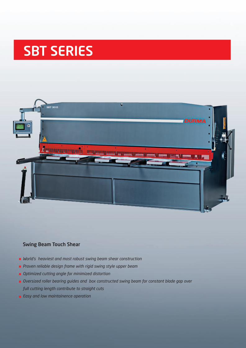
SBT SERIES
Swing Beam Touch Shear
World’s heaviest and most robust swing beam shear construction
Proven reliable design frame with rigid swing style upper beam
Optimized cutting angle for minimized distortion
Oversized roller bearing guides and box constructed swing beam for constant blade gap over
full cutting length contribute to straight cuts
Easy and low maintainence operation
2014_SUBAT_1.indd 42 11.06.2014 08:00

FEATURES
D-Touch 7
CNC Touch Screen Control Unit
Large Color Touch Screen, Lcd: 7", 800 X 480 Tft Lcd DisplayRapid data inputEasy communication, USB Port: Usb port for user usb flash memoryEthernet: RJ-45 10/100M Operating System: Windows CE User Program and Steps: Unlimited Material Type: Unlimited
2014_SUBAT_1.indd 43 11.06.2014 08:00

The first one meter of the finger guard can be flipped up out of the way for easy viewing of the work piece at the point of cut. Holddowns are provided to ensure that the plate is held firmly along the length of the cutting area. The holddowns are distrib-uted in such a way that more are closer at each end of the table. This guarantees not only safer operation at the beginning and end of the cut but also the accuracy for narrow (short) plates at each end of the machine. Each independenty acting holddown is capable of applying high pressure to hold the material being cut at the same time preventing thin and delicate materials from being marked.
Back gauge can swing away at the end of its travel to allow the shearing of unlimited lenght drop pieces. Also available is a swing up style, which swings up and out of the way when the back gauge reaches the end of its range. Both styles allow shearing sheets of an unlimited length.
A Quickset single point blade gap adjustment is conveniently located on the side frame of the machine. The operator can easily and quickly change this setting, as the material type and thick-ness demands, for a high quality blank.
Single Point Blade Clearance
Finger Guard, Ball Transfers & Holddowns
Swing Up Or Away Back Gauge
When shearing long drop pieces of thin material the sheet can droop before it reaches the gauge bar, therefore making it impo ssible to gauge or, at least gauge accurately. In this system support arms which are pneumatically activated support the sheet while gauging and then automatically move away for shearing after the sheet is securely clamped and gauged. This also eliminates the need to front gauge and he need for the operator or additional personel, to manually support the sheet from the rear side of the machine, which is not only costly, but unsafe.
Rear Sheet Support Systm
2014_SUBAT_1.indd 44 11.06.2014 08:00

POSITION 1
( UNLOADING MOVEMENT )
HH1 - PNEUMATIC THIN SHEET SUPPORT SYSTEMSB - VS MACHINE
POSITION 2
Durma 1
Durma 4
2014_SUBAT_1.indd 45 11.06.2014 08:00
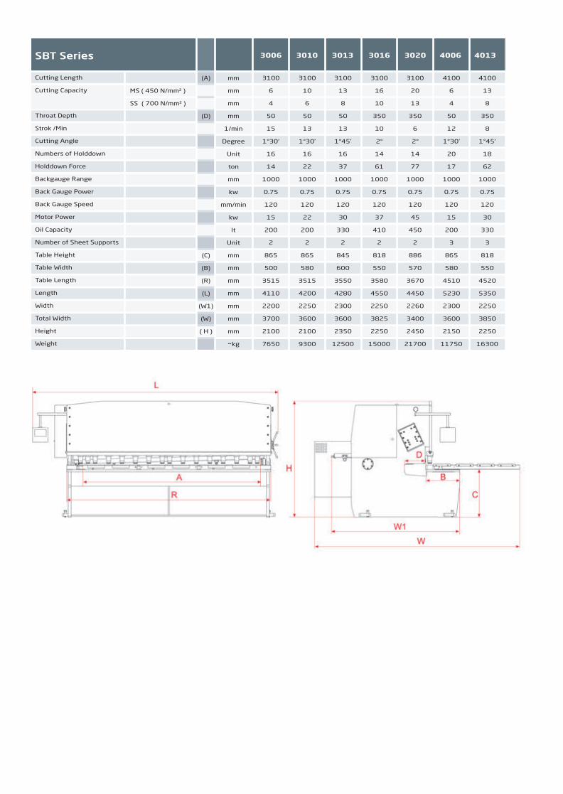
SBT Series
Cutting Length
Cutting Capacity
Throat Depth
Strok /Min
HI-SPEED Strok /Min
Cutting Angle
Numbers of Holddown
Holddown Force
Backgauge Range
Back Gauge Power
Back Gauge Speed
Motor Power
Oil Capacity
Number of Sheet Supports
Table Height
Table Width
Table Length
Length
Width
Total Width
Height
Weight
MS ( 450 N/mm² )
SS ( 700 N/mm² )
3100
6
4
50
15
24
1°30'
16
14
1000
0.75
120
15
200
2
865
500
3515
4110
2200
3700
2100
7650
3100
10
6
50
13
19
1°30'
16
22
1000
0.75
120
22
200
2
865
580
3515
4200
2250
3600
2100
9300
3100
13
8
50
13
18
1°45'
16
37
1000
0.75
120
30
330
2
845
600
3550
4280
2300
3600
2350
12500
3100
16
10
350
10
14
2°
14
61
1000
0.75
120
37
410
2
818
550
3580
4550
2250
3825
2250
15000
3100
20
13
350
6
8
2°
14
77
1000
0.75
120
45
450
2
886
570
3670
4450
2260
3400
2450
21700
4100
6
4
50
12
23
1°30'
20
17
1000
0.75
120
15
200
3
865
580
4510
5230
2300
3600
2150
11750
4100
13
8
350
8
17
1°45'
18
62
1000
0.75
120
30
330
3
818
550
4520
5350
2250
3850
2250
16300
mm
mm
mm
mm
1/min
1/min
Degree
Unit
ton
mm
kw
mm/min
kw
lt
Unit
mm
mm
mm
mm
mm
mm
mm
~kg
(A)
(D)
(C)
(B)
(R)
(L)
(W1)
(W)
( H )
3006 3010 3013 3016 3020 4006 4013
2014_SUBAT_1.indd 46 11.06.2014 08:00

SBT
STANDARD EQUIPMENTS
Heavy duty St 44 steel construction & Stress relieved frame
Userfriendly CNC Touchscreen control unit D-Touch 7
Easy blade gap adjustment
Ball integrated front tables
Ballscrew back gauge, 1000 mm & Automatic swing-up
Squaring arm with scale & T-Slot & Tilting stop (L= 1500 mm)
Support arms T-Slot & Tilting stop (L=1000 mm)
Illumination & Shadow line
1 mt flip-up finger guards
Automatically pressure adjusted solid holddowns
Top and Bottom blades with 4 sides
Foot pedal
High performance hydraulics & electronics components
Swing-up back gauge
OPTIONAL EQUIPMENTS
CE-Norm for EU
Motorized blade gap adjustment
Laser Cutting Line
Light Curtains for Finger Protection
Pneumatic sheet support device standart - Durma I
Pneumatic sheet support device standart - Durma IV
Hydraulic anti-twist device
Special Throat Depth
Backgauge 1250 mm
Add. Support Arms
Adjustable holddown pressure
Special blades
Oil Coolant
Adjustable Angle stop 0-180°
Special color
Control Panel on opposite position
Temperature measurement
Overseas special packaging
2014_SUBAT_1.indd 47 11.06.2014 08:00

Durma Punch Presses
RP Series
Rotational - Head PunchDurable punching operation for cost effective processes
TP Series
Turret PunchFlexible and strong punching processes for each sheet formats
Thousands of Durma Punch Presses all around the world is verifying the quality, reliability and stability of machines ; their stres relieved steel construction, modern design, state of art control system,software and quality proven hydraulics are other distinctive characteristics. Auto clamping, strong and flexible turret structure, simple and perfectly designed standardised supplementary equipments and with its user friendly CAD/CAM software; machines offer perfect full package to our clients. Possible software and parameter problems can be check via “ Remote diagnostic” function of the control unitLoading and unloading systems can be integrated for efficient and lean operationsHigh performance/price ratio Low maintainence costsDurma Punch Presses are designed and produced for value add operations’ for long lifetime.
2014_SUBAT_1.indd 48 11.06.2014 08:00

RP SERIES
Single rotational head machines with versatile C frame construction
Stress relieved steel construction
Powerful Siemens controller with user friendly CAD-CAM Software
Fast and simple operation
High quality and well known hydraulic and electronic components
2014_SUBAT_1.indd 49 11.06.2014 08:00

Control System
Siemens Sinumerik 840 DSL control system is applied for punching with strategic alliance with Siemens. Controls and screen are mounted on a mobile control panel. The control system and other hardware are mounted in a separate cabinet. Machining can be started with just a few steps. Network (ethernet) connection is available as well as programming on the control panel. UPS system prevents the control unit from the voltage fluctuations and cuts.
Integrated online help messages answer all questions at the location they arise. The diagnostic concept provides visual depictions of any function faults. Remote diagnostics is a matter of course over Internet for diagnostics for machine controller.
The control ensures that optimal acceleration values can be attained at every stage of machining, depending on the actual masses that need to be moved.
High rotational speed 40 rpm makes the machine fast.By using zero backlash Harmonic Drive Gear system for index position punching.Automatic reposition in the X axis enables to punch longer than 2 meters and eliminate the death area on the sheet.
Multi Tooling Rotational Head
Durma rotation punch press machine top and bottom tools work synchronize to obtain all required angular pitch can be ± 0,02°.Upper and lower index groups have no mechanical connections which means they can be perfectly aligned, even defect into the tools can be adjusted. It has a wide tooling usage capacity with 3, 6, 8, 10 tools multi tool selection.
FEATURES
2014_SUBAT_1.indd 50 11.06.2014 08:00

DURMA Punch Press is equipped with infra-red barrier system according to CE conformity.
Workchute
Auto Clamps Cadcam Software
Discharges processed small workpieces without interruption or small manual manipulation. (Optional with RP9)
Automatic clamps (standard with RP6 - RP9) position according to the CAM program, sheet remove sensors at clamps detects the sheet hold, in case any possible release machine stops to protect working environment.
Programming time minimized by using fast and easy CAD-CAM software (cncKAD) metalix or LanTek. By choosing the effective position of the tool automatically to use maximum area of the sheet, additional reposition and work strips is eliminated.
2014_SUBAT_1.indd 51 11.06.2014 08:00

RP Series
Maximum tonnage
X axis movement
Y axis movement with multiple tool
Y axis movement with single tool
Max. Cutting thickness
Automatic positioning range *
Speed of Y axis
Speed of X axis
Speed of C axis index
Lateral speed Y + X
Max. Hit rate (1 mm pitch, 1mm thickness)
Max. Hit rate (25 mm pitch, 1mm thickness)
Max. Hit rate : Marking
Accuracy for positioning
Max. weight of sheet
Hard disk
RAM
Network system
LCD colorscreen Super VGA
Working height
Table width
Machine sizes
Motor
Oil tank
Weight approx.
Main cylinder stroke
Maximum punching diameter ( for Multitool )
Number of Clamps
Holding force of clamps
Automatic Clamp Positioning
Table type
ton
mm
mm
mm
mm
mm
m/min
m/min
rpm
m/min
1/min
1/min
Stroke/min
mm
kg
Gbyte
Mb EDO
-
-
mm
mm
mm
kw
lt
kg
mm
mm
pcs.
kg
-
-
30
2000 + R
1250
1285
6
10000
50
60
40
75
600
280
900
± 0.1
120
40
256
Windows XP
12.1’’
980
2400 x 3600
3600 x 4100 x 2450
11
200
12000
30
24
2
1000
-
Brush
20
2000 + R
1250
1285
6
10000
75
96
40
120
850
320
1250
± 0.1
120
40
256
Windows XP
12.1’’
980
2400 x 3600
3600 x 4100 x 2450
7.5
200
12000
30
24
2
1000
Standard
Brush
RP6Unit RP9
2014_SUBAT_1.indd 52 11.06.2014 08:00
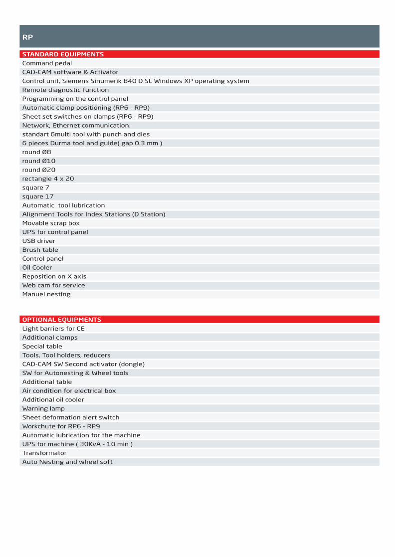
RP
STANDARD EQUIPMENTS
Command pedal
CAD-CAM software & Activator
Control unit, Siemens Sinumerik 840 D SL Windows XP operating system
Remote diagnostic function
Programming on the control panel
Automatic clamp positioning (RP6 - RP9)
Sheet set switches on clamps (RP6 - RP9)
Network, Ethernet communication.
standart 6multi tool with punch and dies
6 pieces Durma tool and guide( gap 0.3 mm )
round Ø8
round Ø10
round Ø20
rectangle 4 x 20
square 7
square 17
Automatic tool lubrication
Alignment Tools for Index Stations (D Station)
Movable scrap box
UPS for control panel
USB driver
Brush table
Control panel
Oil Cooler
Reposition on X axis
Web cam for service
Manuel nesting
OPTIONAL EQUIPMENTS
Light barriers for CE
Additional clamps
Special table
Tools, Tool holders, reducers
CAD-CAM SW Second activator (dongle)
SW for Autonesting & Wheel tools
Additional table
Air condition for electrical box
Additional oil cooler
Warning lamp
Sheet deformation alert switch
Workchute for RP6 - RP9
Automatic lubrication for the machine
UPS for machine ( 30KvA - 10 min )
Transformator
Auto Nesting and wheel soft
2014_SUBAT_1.indd 53 11.06.2014 08:00

TP SERIES
Small, medium and large format sheet processing
Punching,forming,tapping, and wheel technology capabilities
Stress relieved O frame
Flexible turret configurations to elimimate tool setups
Auto lubrication of moving parts
Rigid guides
One of the best controller with functionality & flexibility
Powerful control with user friendly CAD-CAM Software
Programmable sheet clamping system decreases set-up times and scrap ratio
Automation can be easily integrated for efficient and lean operations while
also increasing operator safety and as well as decreasing opertor fatique.
2014_SUBAT_1.indd 54 11.06.2014 08:00

FEATURES
Precise and High Speed Turret
High Quality Forming
(Intelligent Hydraulics
The punching head stroke rates of 1200 strokes per minute during punching and 1800 per minute during marking. Also can be forming at punching speed. The machine control adjusts stroke travel speed and position.
With its dynamic design, it is possible to obtain speeds of 96 m/min in X axis80 m/min in Y axis124 m/min simultaneouslyHigh acceleration (1g) is possible across the whole working range without any restriction.
Advanced ram positioning control by closed loop hydraulic Hartmann Lammle, table axis drive by Siemens servo motors acquire ± 0,1 mm positioning accuracy and ± 0,5 mm repeatable accuracy. Accurate index incremental (0,01°) is provided by very precision bevel gears. Upper and lower angular synchronization is acquired by backlash free 2 servo motor & 2 reducers.
Variable dwell time at bottom of stroke provides high quality, forming, often eliminating secondary processing Electronic adjustment simplifies setup of progressive forms, flanges, and embossments.With roller technology are possible not only on straight geometries but also on curved and round areas. This method is of particular interest for sectors such as air conditioning technology. (Wheel tools, tapping tools)High speed marking
2014_SUBAT_1.indd 55 11.06.2014 08:00
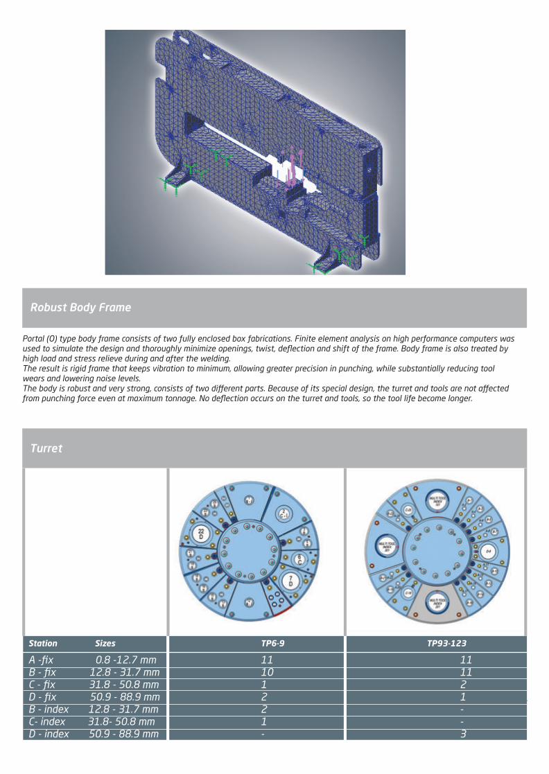
Robust Body Frame
Turret
Portal (O) type body frame consists of two fully enclosed box fabrications. Finite element analysis on high performance computers was used to simulate the design and thoroughly minimize openings, twist, deflection and shift of the frame. Body frame is also treated by high load and stress relieve during and after the welding.The result is rigid frame that keeps vibration to minimum, allowing greater precision in punching, while substantially reducing tool wears and lowering noise levels.The body is robust and very strong, consists of two different parts. Because of its special design, the turret and tools are not affected from punching force even at maximum tonnage. No deflection occurs on the turret and tools, so the tool life become longer.
Station Sizes TP6-9 TP93-123
A -fix 0.8 -12.7 mm 11 11B - fix 12.8 - 31.7 mm 10 11C - fix 31.8 - 50.8 mm 1 2D - fix 50.9 - 88.9 mm 2 1B - index 12.8 - 31.7 mm 2 -C- index 31.8- 50.8 mm 1 -D - index 50.9 - 88.9 mm - 3
2014_SUBAT_1.indd 56 11.06.2014 08:00

Provide maximum flexibility by simplifying tooling inventories and reducing tool setup time.Tools are rotatable in 0.01° increments enabling the processing of complex shaped parts with the minimum number of tools.
Tool change takes less than 3 seconds to complete total turret movement and just 0,6 seconds for single tool.
Forming almost at punching speed by closed loop hydraulic by Bosch - Rexroth. A variable forming position ensures that forming operations can be carried out with minimal stroke travel.
The dies are positioned below the table surface, preventing sheets from being scratched or caught, therefore micro tags can be reduced to minimum for more precision parts.
3 Auto Index Stations Workchute
Reposition
It is possible to process sheet length over table length without need to reposition.
To evacuate parts during punching also with sorting and stacking capacity.
The parts chute, small parts up to 400 x 600 mm can be ejected directly into a parts container. An optional conveyor system.(TP6, TP9 standard, rest optional)
2014_SUBAT_1.indd 57 11.06.2014 08:00

Motion and Table Automatic Clamps
When punching thinner material, one of the problem is to control the sheet movement at non clamping area. To eliminate this matter 3 clamps or more is available.
A new design of X and Y axis, direct drive technology is used. This will increase the performance and eliminates any loses from belts, gears or any transmission systems.
Ball table mainly easy movement of the sheet, brush table is generally for sensitive and soft material punching for not to scratch the sheet.Both is available according to customer demands.
Control System
Siemens Sinumerik 840 DSL control system is applied for punching . Controls and screen are mounted on a mobile control panel. The control system and other hardware are mounted in a separate cabinet. Machining can be started with just a few steps. Network (ethernet) connection is available as well as programming on the control panel. UPS system prevents the control unit from the voltage fluctuations and cuts.
Integrated online help messages answer all questions at the location they arise. The diagnostic concept provides visual depictions of any function faults. Remote diagnostics is a matter of course over Internet for diagnostics for machine controller.
Programming time minimized by using fast and easy CAD-CAM software (cncKAD) metalix or LanTek. By choosing the effective position of the tool automatically to use maximum area of the sheet, additional reposition and work strips is eliminated.
Cadcam Software
2014_SUBAT_1.indd 58 11.06.2014 08:00

Maximum tonnage
Frame type
X axis movement
Y axis movement with single tool
Automatic Repositioning range *
Speed of Y axis
Speed of X axis
Lateral speed Y + X
Max. Hit rate (1 mm pitch, 1mm thickness )
Max. Hit rate (25 mm pitch, 1mm thickness )
Max. Hit rate : Marking
Main cylinder stroke
Maximum punching stroke
Max. cutting thickness (Fixed Station)
Max. cutting thickness (Index Station)
ton
-
mm
mm
mm
m/min
m/min
m/min
1/min
1/min
1/min
mm
mm
Mild Steel
Stainless Steel
Mild Steel
Stainless Steel
30
O Gövde
2000 + R
1250
10000*
70
90
114
600
300
900
40
25
6
3
3
1.5
20
O frame
2000 + R
1250
10000
70
90
114
900
350
1200
40
25
6
3
3
1.5
30
O frame
2500 + R
1250
10000
75
100
125
600
300
900
40
25
6
3
3
1.5
20
O frame
2500 + R
1250
10000
75
100
125
900
350
1200
40
25
6
3
3
1.5
20
O frame
2500 + R
1250
10000
80
116
140
1200
400
1800
40
25
6
3
3
1.5
20
O frame
3000 + R
1500
10000
60
70
92
900
300
1200
40
25
6
3
3
1.5
30
O frame
3000 + R
1500
10000
60
70
92
600
250
900
40
25
6
3
3
1.5
TP Series Birim TP6 TP9 TP63 TP93 TP123 TPL63 TPL93
Positioning accuracy
Repeatable accuracy
Turret rotation speed
Auto index rotational speed
Max. weight of sheet
Hard disk
RAM
Network system
LCD colorscreen Super VGA
USB
Ethernet
Machine dimension
Height (H)
Width (without light barrier) (W)
Width (with light barrier)
Length (without light barrier) (L)
Length (with light barrier)
Table height
Weight approx.
Motor
Oil tank
Air pressure
Number of Clamps
Holding force of clamps
Table type
mm
mm
rpm
rpm
kg
Gbyte
Mb SDRAM
-
-
-
-
mm
mm
mm
mm
mm
mm
kg
kw
lt
bar
pcs.
-
kg
-
± 0.1
± 0.05
30
150
100
40
512
Windows XP
15''
2.0
10/100
2310
4200
6200
5600
6600
940
11000
11
180
6
2
Standard
1000
Fırçalı
± 0.1
± 0.05
30
150
100
40
512
Windows XP
15''
2.0
10/100
2310
4200
6200
5600
6600
940
11000
7.5
180
6
2
Standard
1000
Fırçalı
± 0.1
± 0.05
22
150
120
40
512
Windows XP
15''
2.0
10/100
2310
5360
7360
5750
6800
940
12960
11
180
6
3
Standard
1000
Fırçalı
± 0.1
± 0.05
22
150
120
40
512
Windows XP
15''
2.0
10/100
2310
5360
7360
5750
6800
940
12960
7.5
180
6
3
Standard
1000
Fırçalı
± 0.1
± 0.05
22
150
120
40
512
Windows XP
15''
2.0
10/100
2310
5360
7360
5750
6800
940
12960
15
240
6
3
Standard
1000
Fırçalı
± 0.1
± 0.05
22
150
200
40
512
Windows XP
15''
2.0
10/100
2310
6300
8300
6650
7650
940
19500
7.5
180
6
4
Standard
1000
Fırçalı
± 0.1
± 0.05
22
150
200
40
512
Windows XP
15''
2.0
10/100
2310
6300
8300
6650
7650
940
19500
11
180
6
4
Standard
1000
Fırçalı
TP Serisi Birim TP6 TP9 TP63 TP93 TP123 TPL63 TPL93
A - fix 0.8 -12.7 mm
B - fix 12.8 - 31.7 mm
C - fix 31.8 - 50.8 mm
D - fix 50.9 - 88.9 mm
B - indeks 12.8 - 31.7 mm
C- indeks 31.8- 50.8 mm
D- indeks 50.9 mm to 88.9 mm
11
10
1
2
2
1
-
11
10
1
2
2
1
-
11
11
2
1
-
-
3
11
11
2
1
-
-
3
11
11
2
1
-
-
3
11
11
2
1
-
-
3
11
11
2
1
-
-
3
Taret (kalıp ve tutucu hariç) Birim TP6 TP9 TP63 TP93 TP123 TPL63 TPL93
* : Special table must be added to the machine and the light barriers must be located the correct position. Max.weight 100 kg.
2014_SUBAT_1.indd 59 11.06.2014 08:00

TP
STANDARD EQUIPMENTS
Command pedal
CAD-CAM software & Activator
Control unit, Siemens Sinumerik 840 D SL Windows XP operating system
Remote diagnostic function
Programming on the control panel
Automatic clamp positioning.
Sheet set switches on clamps
Network, Ethernet communication.
Automatic tool lubrication
UPS for control panel
Movable scrap box
Brush table
Oil Cooler
USB Driver
Web cam for service
Reposition on X axis
Alignment Tools for Index Stations (C+B Station) - ( for TP6, TP9)
Alignment Tools for Index Stations (D Station) - (for TP63, TP93, TPL93, TP123)
Manual nesting
OPTIONAL EQUIPMENTS
Light barriers for CE
Additional clamps
Table (brush&ball)
Tools, Tool holders, reducers
CAD-CAM SW Second activator (dongle)
SW for Autonesting, Wheel and Tapping tools
Warning lamp
Sheet deformation alert switch
Turret cover for perforated sheets
Vacuum slug remover
Workchute
Automatic lubrication for the machine
Air condition for electrical box
Additional oil cooler
Loading- Unloading preparation
Loading- Unloading system
Additional table
Special table
Transformator
UPS for machine ( 30KvA - 10 min )
Additional allignment tool
2014_SUBAT_1.indd 60 11.06.2014 08:00

Durma Laser Cutting MachinesA modular product family of state-of-the-art flying optics laser cutting machines where the cutting head moves accurately and with high dynamics over the work piece. There are solutions for different sheet sizes, with optimal laser technologies for every range of materials and thicknesses, and all are driven by high performance and maintenance free rack and pinion or linear motor motion systems.
HD Series
The HD series of CO2 laser machines allow high-quality cutting of both thin and thick material sections and offers top performances at minimal running costs.
HD-F Series
Machine with fiber laser source which offer very high quality cutting and performance on a wide variety of material types with low energy consumption.
1kW2kW2.5kW3kW3.5kW4kW4.5kWConveyorsShuttle tableAuto-focus headTube cuttingCELL
HDF Smart
xo-o-o-o-oo-
LinearHDFL 3015
-x-o-o-oxxoo
Rack & Pinion
HD 3015--o-x-ooxxoo
Linear
HDL 3015--o-x-ooxxoo
HDF 3015
ox-o-o-oxxoo
Configuration3015
Fiber CO2
Rack & Pinion
1kW2kW2.5kW3kW3.5kW4kW4.5kWConveyorsShuttle tableAuto-focus headTube cuttingCELL
Configuration4020
Rack & Pinion
HD 4020--o-x-ooxx-o
Linear
HDL 4020--o-x-ooxx-o
CO2 Rack & Pinion
HDF 4020ox-o-o-oxx-o
Linear
HDFL 4020-x-o-o-oxx-o
Fiber6020
Rack & Pinion
HDF 6020ox-o-o-oxx--
Linear
HDFL 6020-x-o-o-oxx--
Fiber8020
Rack & Pinion
HDF 8020ox-o-o-oxx--
Linear
HDFL 8020-x-o-o-oxx--
Fiber
(x) Standard (o) Optional (-) Not Available
2014_SUBAT_1.indd 61 11.06.2014 08:00

The diffusion cooled laser source provides a high beam quality at laser powers up to 4kW with a minimal running cost compared with other CO2 laser technologies. The laser is immediately ready for use when powering on the machine and consumes no energy when it is in stand-by.
CO2 LASER TECHNOLOGY
Maintenance There are no major parts in the laser that are subject to mechanical wear, there is no electrode erosion inside the vacuum chamber that could contaminate internal optics and there is an absence of brittle glass tubes to contain the laser me-dium. These unique features allow an extremely low routine maintenance: both in part cost and in down-time.
Laser gasSince the electrodes that provide the power to the electrical discharge in the laser medium are not in contact with the la-ser gas, the gas does not get contaminated and allows the laser to operate three days without the need of refreshing it.
Beam Delivery System The laser beam propagates through a completely closed beam delivery system over-pressurized by clean, dry air.The laser beam preserves its excellent quality and has constant characteristics all over the working area.
Quality Fiber Quality CO2 Speed Fiber Speed CO2
Cutting Speed / Material Thickness (Assist gas N²)
2014_SUBAT_1.indd 62 11.06.2014 08:00

The laser power source of the HDF series is an all-solid-state fiber laser. This technology reduces further the maintenance requirements, and offers the lowest possible running cost with a wall-plug efficiency of 30% and without the need of any laser gas. When the applica-tion requires a broader spectrum of material types to be cut and the maximum thickness range is limited, the fiber laser is the ideal solution: it will cut faster at lower cost than any CO2 laser at the same laser power.
FIBER LASER TECHNOLOGY
MaintenanceFiber lasers are all solid state and have no mechanical parts that could suffer from wear or need adjustment. The laser source is therefore truly maintenance free and has an expected life time of > 100,000h.
Laser gasWhere CO2 lasers are excited by an electrical discharge in a laser gas medium, fiber lasers are powered by diode lasers and require no gas for their operation.
Beam Delivery System The fiber laser light is brought from the laser source to the cutting head by a flexible glass fiber. There are no mirrors in the beam delivery that require maintenance and adjustment. The light does not travel through air, making a flush-ing or over-pressurizing with clean air unnecessary.
Reduced power consumptionNot only will fiber lasers cut faster than CO2 lasers with a similar output power, their wall-plug efficiency of 30% is more than double. There is no stand-by electrical consumption and also the cooling requirements are only a fraction of the ones for a CO2 laser.
Quality Fiber Quality CO2 Speed Fiber Speed CO2
Cutting Speed / Material Thickness (Assist gas O²)
Fiber CO2
Cost
Maintenance PowerConsumption
Compressed Air
2014_SUBAT_1.indd 63 11.06.2014 08:00

GENERAL FEATURES
THE WINNING FORCE / LASER CUTING MACHINES
Scrap conveyorThe optional lateral automatic scrap conveyors allow the removal of scrap pieces from the working area without the need to interrupt the cutting process. The sideways operation of the short conveyors allow for easy maintenance and trouble-free running.
Control Unit Durma laser machines achieve the highest dynamics and the fastest laser processing cycle times thanks to the combination of rigid mechanics and a state-of-the-art numerical control and drive system.
The graphical user interface ensures an easy operation of the machine and the on-board libraries of reference cutting parameters for various materials and thicknesses allow the operator to achieve optimal cutting results in a minimum amount of time.
Programs can be loaded easily into the machine with a USB stick or over a fast Ethernet connection with the company network.
Rigid Frame & Gantry The foundation basis of all Durma laser machines is a rigid stress-relieved welded steel frame construction upon which a sti� gantry axis system moves the cutting head. The design guarantees accurate parts even when cutting with the fastest speeds and under the highest accelerations.
Shuttle TableIntegrated shuttle tables are incorporated on the laser machine to maximize the productivity and minimize the material handling times. The shuttle table and pallet change system allows convenient loading of new sheets or unloading of finished parts while the machine is cutting another sheet inside the working area .
The available shuttle tables on all machine models are fully electric and maintenance free: there are no hydraulic oils to handle and the table changes take place fast, smooth and energy-e�cient.
Linear motorsState-of-the-art linear motors narrow down further the accuracy of the machine and o�er higher dynamics than the rack and pinion system. When the application demands high precision and/or require many positioning movements between complex shaped features, the linear motors will reduce the dead times in the process and increase the productivity.
Cutting Head İn the high-pressure auto-focus cutting head for fiber lasers the cutting lens is shielded from the laser process by an exchange-able low-cost protection window. The 1µm wavelength light of fiber lasers is very sensitive to dust or other contamination produced in the cutting or piercing process, therefore the cutting head is being well protected in an additional cover to ensure that all critical parts remain as clean as possible . The integrated capacitive distance sensor is capable of having the head follow height di�erences in the sheet even at the extreme high cutting speeds that can be achieved with the fiber laser technology.
CAD/CAM Software The CAD/CAM software provided with the machine has all the tools to import or draw parts, prepare and optimize automati-cally the di�erent geometries for the laser cutting process and make e�cient nests.
THE WINNING FORCE / LASER CUTING MACHINES
2014_SUBAT_1.indd 64 11.06.2014 08:01

GENERAL FEATURES
THE WINNING FORCE / LASER CUTING MACHINES
Scrap conveyorThe optional lateral automatic scrap conveyors allow the removal of scrap pieces from the working area without the need to interrupt the cutting process. The sideways operation of the short conveyors allow for easy maintenance and trouble-free running.
Control Unit Durma laser machines achieve the highest dynamics and the fastest laser processing cycle times thanks to the combination of rigid mechanics and a state-of-the-art numerical control and drive system.
The graphical user interface ensures an easy operation of the machine and the on-board libraries of reference cutting parameters for various materials and thicknesses allow the operator to achieve optimal cutting results in a minimum amount of time.
Programs can be loaded easily into the machine with a USB stick or over a fast Ethernet connection with the company network.
Rigid Frame & Gantry The foundation basis of all Durma laser machines is a rigid stress-relieved welded steel frame construction upon which a sti� gantry axis system moves the cutting head. The design guarantees accurate parts even when cutting with the fastest speeds and under the highest accelerations.
Shuttle TableIntegrated shuttle tables are incorporated on the laser machine to maximize the productivity and minimize the material handling times. The shuttle table and pallet change system allows convenient loading of new sheets or unloading of finished parts while the machine is cutting another sheet inside the working area .
The available shuttle tables on all machine models are fully electric and maintenance free: there are no hydraulic oils to handle and the table changes take place fast, smooth and energy-e�cient.
Linear motorsState-of-the-art linear motors narrow down further the accuracy of the machine and o�er higher dynamics than the rack and pinion system. When the application demands high precision and/or require many positioning movements between complex shaped features, the linear motors will reduce the dead times in the process and increase the productivity.
Cutting Head İn the high-pressure auto-focus cutting head for fiber lasers the cutting lens is shielded from the laser process by an exchange-able low-cost protection window. The 1µm wavelength light of fiber lasers is very sensitive to dust or other contamination produced in the cutting or piercing process, therefore the cutting head is being well protected in an additional cover to ensure that all critical parts remain as clean as possible . The integrated capacitive distance sensor is capable of having the head follow height di�erences in the sheet even at the extreme high cutting speeds that can be achieved with the fiber laser technology.
CAD/CAM Software The CAD/CAM software provided with the machine has all the tools to import or draw parts, prepare and optimize automati-cally the di�erent geometries for the laser cutting process and make e�cient nests.
THE WINNING FORCE / LASER CUTING MACHINES
2014_SUBAT_1.indd 65 11.06.2014 08:01
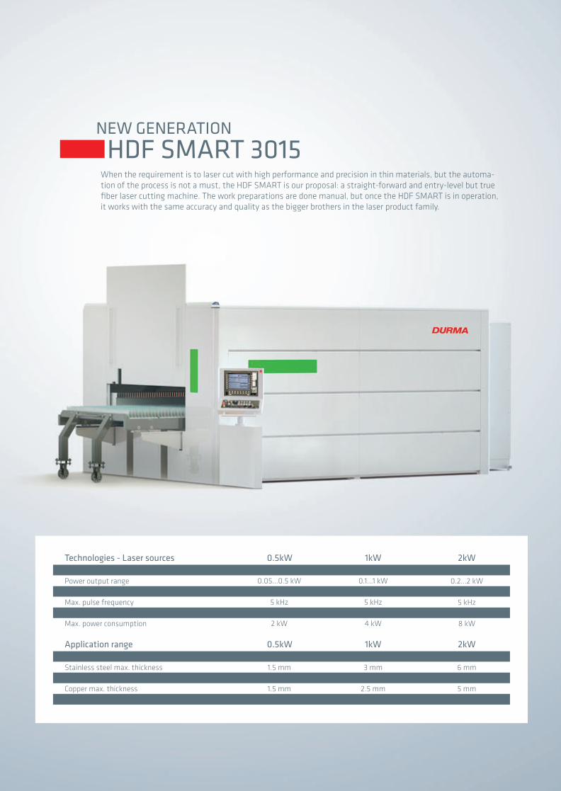
NEW GENERATION
HDF SMART 3015When the requirement is to laser cut with high performance and precision in thin materials, but the automa-tion of the process is not a must, the HDF SMART is our proposal: a straight-forward and entry-level but true fiber laser cutting machine. The work preparations are done manual, but once the HDF SMART is in operation, it works with the same accuracy and quality as the bigger brothers in the laser product family.
WavelengthPower output rangePolarizationMax. pulse frequencyGas consumptionMax. power consumption
Technologies - Laser sources
Mild steel max. thicknessStainless steel max. thicknessAluminum max. thicknessCopper max. thicknessBrass max. thickness
Application range
1070...1080 nm0.05...0.5 kW
Random5 kHz
-2 kW
0.5kW
4 mm1.5 mm1.5 mm1.5 mm1.5 mm
0.5kW
1070...1080 nm0.1...1 kWRandom
5 kHz-
4 kW
1kW
8 mm3 mm
2.5 mm2.5 mm3 mm
1kW
1070...1080 nm0.2...2 kWRandom
5 kHz-
8 kW
2kW
15 mm6 mm5 mm5 mm6 mm
2kW
2014_SUBAT_1.indd 66 11.06.2014 08:01

HDF SMART 3015 TECHNICAL DATAEconomic Easy to useFast
Lay-out area Machine heightMachine widthMachine lengthMachine weight
9700 mm x 5700 mm2420 mm4050 mm9150 mm9000 kg
Dimensions
X-axisY-axisZ-axisMax. sheet sizeMax. sheet weight
3060 mm1550 mm200 mm
3000 mm x 1500 mm500 kg
Working range
Max. speed X-axisMax. speed Y-axisMax. speed simultaneousMax. acceleration X-axisMax. acceleration Y-axisMax. acceleration simultaneousPositional accuracyRepeatability
90 m/min120 m/min150 m/min10 m/s^210 m/s^214 m/s^20.05 mm0.05 mm
Dynamics
9273
2014_SUBAT_1.indd 67 11.06.2014 08:01

NEW GENERATION
FIBER LASER HDF / HDFL 3015 The laser power source of the HDF series is an all-solid-state fiber laser. This technology reduces further the mainte-nance requirements, and offers the lowest possible running cost with a wall-plug efficiency of 30% and without the need of any laser gas. When the application requires a broader spectrum of material types to be cut and the maxi-mum thickness range is limited, the fiber laser is the ideal solution: it will cut faster at lower cost than any CO2 laser at the same laser power.
WavelengthPower output rangePolarizationMax. pulse frequencyGas consumptionMax. power consumption
Technologies - Laser sourcesType HDF HDF / HDFL
Mild steel max. thicknessStainless steel max. thicknessAluminum max. thicknessCopper max. thicknessBrass max. thickness
Application range
1070...1080 nm0.1...1 kWRandom
5 kHz-
4 kW
1kW
6 mm3 mm
2.5 mm2.5 mm3 mm
1070...1080 nm0.2...2 kWRandom
5 kHz-
8 kW
2kW
15 mm6 mm5 mm5 mm6 mm
20 mm10 mm8 mm8 mm8 mm
1070...1080 nm0.3...3 kWRandom
5 kHz-
12 kW
3kW
25 mm12 mm10 mm10 mm10 mm
1070...1080 nm0.4...4 kWRandom
5 kHz-
16 kW
4kW
2014_SUBAT_1.indd 68 11.06.2014 08:01

HDF / HDFL 3015 TECHNICAL DATAEconomic Easy to useFast
Lay-out area Machine heightMachine widthMachine lengthMachine weight
9700 mm x 5700 mm2420 mm4050 mm10150 mm12000 kg
Dimensions HDF HDFL
X-axisY-axisZ-axisMax. sheet sizeMax. sheet weight
3060 mm1550 mm200 mm
3000 mm x 1500 mm1000 kg
Working range
Max. speed X-axisMax. speed Y-axisMax. speed simultaneousMax. acceleration X-axisMax. acceleration Y-axisMax. acceleration simultaneousPositional accuracyRepeatability
200 m/min200 m/min280 m/min20 m/s^220 m/s^228 m/s^20.02 mm0.02 mm
9700 mm x 5700 mm2420 mm4050 mm10150 mm12000 kg
3060 mm1550 mm200 mm
3000 mm x 1500 mm1000 kg
90 m/min120 m/min150 m/min10 m/s^210 m/s^214 m/s^20.05 mm0.05 mm
Dynamics
9700
11500
2254
6750
3300
5700
1300
2014_SUBAT_1.indd 69 11.06.2014 08:01

NEW GENERATION
FIBER LASER HDF / HDFL 6020 The laser power source of the HDF series is an all-solid-state fiber laser. This technology reduces further the mainte-nance requirements, and offers the lowest possible running cost with a wall-plug efficiency of 30% and without the need of any laser gas. When the application requires a broader spectrum of material types to be cut and the maxi-mum thickness range is limited, the fiber laser is the ideal solution: it will cut faster at lower cost than any CO2 laser at the same laser power.
WavelengthPower output rangePolarizationMax. pulse frequencyGas consumptionMax. power consumption
Technologies - Laser sourcesType HDF / HDFL
Mild steel max. thicknessStainless steel max. thicknessAluminum max. thicknessCopper max. thicknessBrass max. thickness
Application range
1070...1080 nm0.2...2 kWRandom
5 kHz-
8 kW
2kW
15 mm6 mm5 mm5 mm6 mm
20 mm10 mm8 mm8 mm8 mm
1070...1080 nm0.3...3 kWRandom
5 kHz-
12 kW
3kW
25 mm12 mm10 mm10 mm10 mm
1070...1080 nm0.4...4 kWRandom
5 kHz-
16 kW
4kW
2014_SUBAT_1.indd 70 11.06.2014 08:01

Lay-out area Machine heightMachine widthMachine lengthMachine weight
18600 mm x 7500 mm2530 mm4800 mm17250 mm26500 kg
Dimensions HDF HDFL
X-axisY-axisZ-axisMax. sheet sizeMax. sheet weight
6150 mm2100 mm200 mm
6000 mm x 2000 mm2500 kg
Working range
Max. speed X-axisMax. speed Y-axisMax. speed simultaneousMax. acceleration X-axisMax. acceleration Y-axisMax. acceleration simultaneousPositional accuracyRepeatability
200 m/min200 m/min280 m/min20 m/s^220 m/s^228 m/s^20.02 mm0.02 mm
18600 mm x 7500 mm2530 mm4800 mm17250 mm26500 kg
6150 mm2100 mm200 mm
6000 mm x 2000 mm2500 kg
90 m/min120 m/min150 m/min10 m/s^210 m/s^214 m/s^20.05 mm0.05 mm
Dynamics
2014_SUBAT_1.indd 71 11.06.2014 08:01

NEW GENERATION
CELL
The Durma Laser CELL for automatic loading and unloading of sheets is probably the most compact solution in the industry, offering a maximum of flexibility on a minimum of required floor-space.
2014_SUBAT_1.indd 72 11.06.2014 08:01

Lay-out area Machine heightMachine widthMachine lengthMachine weight
12000 mm x 7500 mm6340 mm4030 mm3500 mm8000 kg
Dimensions
Max. sheet dimensionMin. sheet dimensionMax. sheet thicknessMin. sheet thicknessMax. sheet weightMax. height on unloading table (incl. pallet)Max. weight on unloading tableMax. height on loading table (incl. pallet)Max. weight on loading table
3048 mm1534 mm25 mm0.5 mm1000 kg300 mm3000 kg300 mm3000 kg
Working range
CELL TECHNICAL DATA
Economic Easy to useFast
Two different lay-outs are possible and the system can be adapted for integration to automatic storages.
The CELL is a full-functional system expansion of the laser cutting machine: work queues of several sheets are activated by pressing one single button and there is no separate control panel for the loading/unloading unit.
When the productivity of a laser machine needs to be increased or when the material handling and flow in a factory needs to be opti-mized, the Durma Laser CELL will be the most efficient and most economic solution.
2014_SUBAT_1.indd 73 11.06.2014 08:01

NEW GENERATION
CO2 LASER HD / HDL 3015The diffusion cooled laser source provides a high beam quality at laser powers up to 4kW with a minimal running cost compared with other CO2 laser technologies. The laser is immediately ready for use when powering on the machine and consumes no energy when it is in stand-by.
Mild steel max. thicknessStainless steel max. thicknessAluminum max. thickness
Application range
WavelengthPower output rangePolarizationMax. pulse frequencyGas consumption
Technologies - Laser sources
12 mm5 mm4 mm
10.6 µm0.25...2.5 kW
Linear5 kHz
0.4 Nl/h
2.5kW
20 mm10 mm8 mm
10.6 µm0.35...3.5 kW
Linear5 kHz
0.4 Nl/h
3.5kW
25 mm12 mm10 mm
10.6 µm0.45...4.5 kW
Linear5 kHz
0.4 Nl/h
4.5kW
2014_SUBAT_1.indd 74 11.06.2014 08:01

HD / HDL 3015 TECHNICAL DATAEconomic Easy to useFast
Lay-out area Machine heightMachine widthMachine lengthMachine weight
13000 mm x 7000 mm2420 mm4050 mm11500 mm13000 kg
Dimensions HD HDL
X-axisY-axisZ-axisMax. sheet sizeMax. sheet weight
3060 mm1550 mm200 mm
3000 mm x 1500 mm1000 kg
Working range
Max. speed X-axisMax. speed Y-axisMax. speed simultaneousMax. acceleration X-axisMax. acceleration Y-axisMax. acceleration simultaneousPositional accuracyRepeatability
200 m/min200 m/min280 m/min20 m/s^220 m/s^228 m/s^20.02 mm0.02 mm
13000 mm x 7000 mm2420 mm4050 mm11500 mm13000 kg
3060 mm1550 mm200 mm
3000 mm x 1500 mm1000 kg
90 m/min120 m/min150 m/min10 m/s^210 m/s^214 m/s^20.05 mm0.05 mm
Dynamics
13000
4260
7000
3290
6900
2014_SUBAT_1.indd 75 11.06.2014 08:01

Laser Cutting Samples
Quality CuttingCorrect dimension
Clean Cutting
Versatile Cutting
Reilable Cutting
Fast Cutting
2014_SUBAT_1.indd 76 11.06.2014 08:01

DURMA PLASMA CUTTING MACHINESPlasma machines offer quality, efficiency, lower cutting cost and wide range of cutting of mild steel, stainless steel and aluminium.
High performance machines provide the best cutting angles and long consumable life for the customer’s needs by using the world class plasma equipments and control systems.
PL Series
Rail Type Plasma Cutting Machine
High Definition Cutting for Heavy Duty Productivity
PL-C Series
Compact Plasma Cutting Machine
High Definition, Flexible, Small Footprint Cutting Solution
2014_SUBAT_1.indd 77 11.06.2014 08:01

PL SERIESDurma uses only the best in components which include a Siemens motion con-trol system and a Hypertherm supply source. A strong effort has been made to provide the following;
Best cut angleBest edge qualityPrecise & fast positioningLong consumable lifeEasy programmingEasy setupReliability Energy efficientClean operation
The PL Series is built manufactured as a true precision machine tool. These high performance plasma cutting machines are designed to cut a wide range of mild steel, stainless steel and aluminum. The PL is equipped with well known, reliable, and readily available components.
High positioning speeds, accelerations and automatic torch height control provide the best in high quality efficient cutting. The 2D cutting system is available in standard as well as custom lengths and widths.
2014_SUBAT_1.indd 78 11.06.2014 08:01

2014_SUBAT_1.indd 79 11.06.2014 08:01
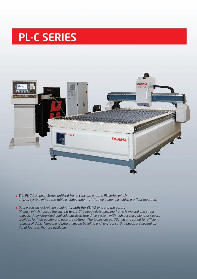
PL-C SERIES
The PL-C (compact) Series unitized frame concept, and the PL series which utilizes system where the table is independent of the two guide rails which are floor mounted.
Dual precision rack/pinion guiding for both the Y1, Y2 axis and the gantry (X axis), which houses the cutting torch. The heavy duty machine frame is welded and stress relieved. A synchronized dual side backlash free drive system with high accuracy planetary gears provides for high quality and accurate cutting. The tables are partitioned and zoned for efficient removal of dust. Manual and programmable beveling and oxyfuel cutting heads are several op-tional features that are available.
2014_SUBAT_1.indd 80 11.06.2014 08:01

Plasma Source
HPR XD Series is used as the plasma source. It is available in 130,260, and 400 amp capacities.Manual or Automatic gas control consoles are available to assure the best cutting gas ratio is achieved. For labeling and identification purposes, a marking feature is included. The system is supplied with laser locating device. A laser beam is used to locate the x and y coordinates of the sheet. This allows the cutting axis to know exactly where it is with respect to the sheet. Faster setup and more accurate cutting.
Patented HyDefinition technology aligns and focuses the plasma arc, improving arc stability and energy for more powerful precision cutting.Narrow kerf width enables fine feature cutting and minimizes material waste. Robust, dross-free cutting minimizes part clean-up. Repeatable cut-edge quality eliminates scrap and rework. Improved hole and internal shape cuts rival laser quality at lower cost.
Hydefinition Cutting
Work Piece
Hypertherm’s X-Y ARG GLIDE THC is a torch height control system designed for plasma cutting applications on an X-Y cutting table. The system uses the plasma arc voltage to control the physical stand-off (distance) between the torch and workpiece during plasma arc cutting. Initial height sensing (IHS) is accomplished by ohmic contact sensing or by a limited force stall detection method.
Also the used equipment called Breakaway protects the plasma torch against crashing by sending an interrupt signal.
Torch Height Control
2014_SUBAT_1.indd 81 11.06.2014 08:01

True Hole Technology
Hypertherm’s True Hole cutting technology for mild steel is exclusively available for use on Hypertherm’sHPRXD auto gas plasma systems and is automatically applied by our cutting optimization and nesting software and CNC software to holes up to 1" with hole diameter to thickness ratios as low as 1:1.
True Hole technology is a specific combination of the followingparameters that is linked to a given amperage, material type,material thickness and hole size:• Process gas type• Gas flow• Amperage• Piercing methodology• Lead in/out technique• Cut speed• Timing
True Hole Technology requires a HyPerformance Plasma HPRXD auto gas system alongwith a True Hole enabled cutting table, nesting software, CNC, and torch height control.
Hypertherm’s patent-pending True Hole cutting technology for mild steel produces significantly better hole quality than what has been previously possible using plasma. This is delivered automatically without operator intervention, to produce unmatched hole quality that surpasses the competition.
1(2( hole without True Hole technologycut with HPRXD( Plasma
1(2( hole with True Hole technologycut with HPRXD( Plasma
2014_SUBAT_1.indd 82 11.06.2014 08:01

The SINUMERIK 840Disl is a fully PC-integrated numerical control system for up to 20 axes, interworking with the SINAMICS S120 drive system.
The control has open hardware and software functions and is ideally suited for users requiring distributed automation solutions with regard to PLC I/Os and drives and/or prefer a fully PC-integrated control system.
Durma has a own plasma software on Sinumerik controller. The operator can load the operation parameters to the power supply easily. Some simple shapes can be loaded from the included improvable library. The cutting operations is shown on the screen during cutting. Controller can be connected to the computer or a LAN via Ethernet connection point.
If the customers want, they control the plasma filter unit by pressing any button on the control panel or automatically when the cutting starts.
Machine searches the plate, finds the Operation Zero position and calculates the Plate Angle automatically.
CNC Control Unit
Metalix software is available for easy programming and drawing of parts. It also easily and quickly converts DXF and DWG files to machine language for cutting.
The automatic nesting feature looks at the multiple parts to be cut from the sheet, and then organizes them on the sheet in the most efficient way. Lower material costs.
CAD Cam Software
2014_SUBAT_1.indd 83 11.06.2014 08:01

Patented LongLife technology significantly improves consumable life. Exceptional cutting speeds produce more finished parts per set of consumables. HyPerformance consumables are engineered for higher quality with lower cost.
Longer Consumable Life
During the thermal cutting process, a large amount of harmful dust particles are created. This dust is harmful to personnel, the environment, and the machines. Therefore it is important to use a filtration system for optimum extraction of these particles and provide a clean air working environment.
Fume Extraction System
Oxy-fuel cutting heads are available to allow the cutting of thicker mild steel.
OXY Cut
Plasma technology uses air for cutting and/or shield gas. This air must be clean, dry, and oil free. In this case an air dryer must be used.
Air Dryer
All cutting tables are partitioned in to different zones. Each zone is equipped with electro pneumatic switch which are automatically controlled by the CNC when the torch is cutting in that zone. This enhances exhaust capabilities and reduces the size requirement of the filtration system.
Cutting Tables
2014_SUBAT_1.indd 84 11.06.2014 08:01

Plasma Bevelling Head
Plasma Cutting Machine with loading unloading system
Drilling Head
2014_SUBAT_1.indd 85 11.06.2014 08:01

STANDARD EQUIPMENTS
Siemens 840 D-ISL CNC control Unit
Solid & CNC machined steel frames
Robust bridge
CAD CAM Software with Auto nesting
Cutting plate alignment function with Laser diode
Plasma ignition consol
Command Torch High Control (THC)
Two side motion control system (low backlash reducers + rack / pinion)
AC Digital Servomotors on axes
Marking system
CNC control outputs/inputs for filter unit
Spare parts ,consumables starting kit
High mechanical accuracy to +- 0,1 mm
Axis positioning speed 35 m/min.
Torch height control travel with ballscrew on dual linear guides
Independent cutting tables
Speed control device
Table incl PL-C series
Remote diagnostics via Ethernet
Rack&Pinion with linear guide ( PL-C Series)
Thick slats on table
Tables suitable for right suction
Web cam for service
PL & PL-C
OPTIONAL EQUIPMENTS
Table for PL series
Hypertherm Plasma source
Automatic gas consol
Manuel gas consol
Filter
Plasma Torch brake away system
Additional plasma torch (Plasma Torch, Torch High Control (THC), İgnition consol)
Additional Oxy-fuel Torch (Oxy -fuel torch, Oxy torch high control, Oxy torch
high sensor) (max. 2 oxy torch)
Bridge preparation for additional torch (plazma or oxy)
Manuel torch tilting system ± 45°
CNC controlled torch tilting system ± 45°
3D Cutting & Rotator
Safety light barrier
Fault and Program end signal lamp
Air dryer
Arcglide THC Torch Height Control ( instead of Command THC)
Drilling Spindle
Loading & Unloading systems
Special applications
Consumables
2014_SUBAT_1.indd 86 11.06.2014 08:01
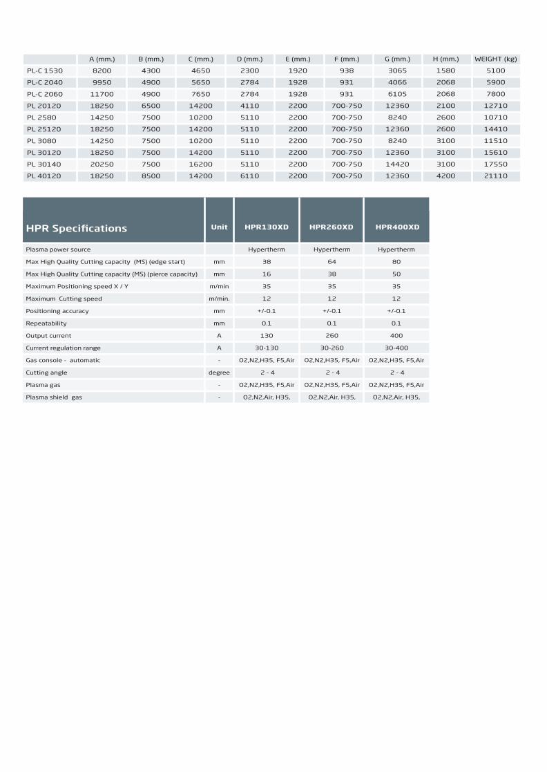
PL-C 1530
PL-C 2040
PL-C 2060
PL 20120
PL 2580
PL 25120
PL 3080
PL 30120
PL 30140
PL 40120
A (mm.)
8200
9950
11700
18250
14250
18250
14250
18250
20250
18250
B (mm.)
4300
4900
4900
6500
7500
7500
7500
7500
7500
8500
C (mm.)
4650
5650
7650
14200
10200
14200
10200
14200
16200
14200
D (mm.)
2300
2784
2784
4110
5110
5110
5110
5110
5110
6110
E (mm.)
1920
1928
1928
2200
2200
2200
2200
2200
2200
2200
F (mm.)
938
931
931
700-750
700-750
700-750
700-750
700-750
700-750
700-750
G (mm.)
3065
4066
6105
12360
8240
12360
8240
12360
14420
12360
WEIGHT (kg)
5100
5900
7800
12710
10710
14410
11510
15610
17550
21110
H (mm.)
1580
2068
2068
2100
2600
2600
3100
3100
3100
4200
HPR Specifications
Plasma power source
Max High Quality Cutting capacity (MS) (edge start)
Max High Quality Cutting capacity (MS) (pierce capacity)
Maximum Positioning speed X / Y
Maximum Cutting speed
Positioning accuracy
Repeatability
Output current
Current regulation range
Gas console - automatic
Cutting angle
Plasma gas
Plasma shield gas
Unit
Hypertherm
38
16
35
12
+/-0.1
0.1
130
30-130
O2,N2,H35, F5,Air
2 - 4
O2,N2,H35, F5,Air
O2,N2,Air, H35,
Hypertherm
80
50
35
12
+/-0.1
0.1
400
30-400
O2,N2,H35, F5,Air
2 - 4
O2,N2,H35, F5,Air
O2,N2,Air, H35,
Hypertherm
64
38
35
12
+/-0.1
0.1
260
30-260
O2,N2,H35, F5,Air
2 - 4
O2,N2,H35, F5,Air
O2,N2,Air, H35,
mm
mm
m/min
m/min.
mm
mm
A
A
-
degree
-
-
HPR130XD HPR260XD HPR400XD
2014_SUBAT_1.indd 87 11.06.2014 08:01

2014_SUBAT_1.indd 88 11.06.2014 08:01