dust explosions
DESCRIPTION
Methods to prevent dust explosionsTRANSCRIPT

dust-explosion protectionthe basics of
staubEX_e_04_10_04.qxd 21.10.2004 12:49 Uhr Seite 33

R. STAHL Explosion protection
Powders or dust like substances are processed or are byproducts of the production process in
many industries.
Whether the dust is useful (e.g. for the production of plastics, pigments or pharmaceuticals)
or waste, a large majority of dustlike substances pose the danger of fire or possibly even
explosions. Eighty percent of all industrial dusts are combustible, and even a dust layer of 1 mm
in a closed room is sufficient to result an explosion when the dust is swirled up and ignited.
These facts, combined with the fact that those affected are not sufficiently aware of the danger
(in contrast to the hazard of gas explosions) underlines the importance of preventing dust
explosions. This brochure is intended to help you analyse the risk of a dust explosion in your
facilities and to take the suitable technical and organisational steps to minimise this risk.
staubEX_e_04_10_04.qxd 21.10.2004 12:47 Uhr Seite 2
R. STAHL Explosion protection
4
6
10
12
14
16
22
28
30
contents
Dust as a Risk Factor
Definitions and Characteristics
Legal Basis and Standards
4 Dust Explosion Protection Measures
5 Classification of Dust Explosion Hazardous Areas into Zones
6 Dust Types of Protection
7 Equipment Selection
8 Installation and Maintenance
Product Overview
1
2
3
4
5
6
7
8
9
staubEX_e_04_10_04.qxd 21.10.2004 12:48 Uhr Seite 3

dust as a risk factor4
dust-explosion protection
1. Dust as a Risk Factor
As with flammable liquids and the explosivegas/air mixtures that result from them, certainconditions must be fulfilled to ignite a mixture ofdust and air by an effective ignition source and thus trigger an explosion. No explosion can occur if one of the following is not present: combustible dust, air, ignition source.
Dust explosions have a different process of propagation than gas explosions and can in somecases be much more devastating. If a gas/air mixture is ignited, the force of the resulting ex-plosion causes the gas cloud to dissipate rapidly and thus dilutes the gas/air mixture to a concentration lower than that necessary for furthercombustion. Thus, if no further gas is added, theexplosion is over after several milliseconds.
With combustible dusts it is different. If, for example, a draft of air swirls up a layer of dust ina small area, the dust, along with oxygen, forms a combustible dust/air mixture. If this mixture isignited by an ignition source, an explosion iscaused. The force of the resulting explosion swirlsup more dust, which is in turn ignited. This pro-
cess continues, and under some conditions chain reactions such as these sweep through entirebuildings or facilities, destroying them.
As is the case with gases, there are various ignition sources for dusts, such as sparks from electrical or mechanical processes, arcs, open flames, electrostatic discharges, electro-magnetic waves and others.
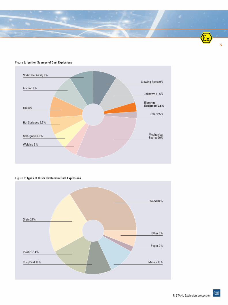
Figure 2 shows the results of statistical studies inNorth America, which examined the distribution of the ignition sources that caused dust explosions.It shows that mechanically produced sparks were responsible in almost one third of the cases.Add to that the 13% of explosions caused by openfire and welding, and it becomes obvious that many people are not aware of the danger of dustexplosions. Figure 3 shows that a wide variety of industries are affected, including branches of thefood and wood processing industries, paper andplastics materials production, pharmaceuticalsproduction and others.
The data given above are confirmed by Germanproperty insurers, who state that on average there is one dust explosion per day in the FederalRepublic of Germany. Approximately one fourth of these are caused by dust from food products oranimal feed.
R. STAHL Explosion protection
Figure 1: Explosion Risk Triangle
1
staubEX_e_04_10_04.qxd 21.10.2004 12:48 Uhr Seite 4
5
R. STAHL Explosion protection
Figure 3: Types of Dusts Involved in Dust Explosions
Figure 2: Ignition Sources of Dust Explosions
staubEX_e_04_10_04.qxd 21.10.2004 12:48 Uhr Seite 5

definitions and characteristics6
dust-explosion protection
2. Definitions and Characteristics
What does the word dust really mean? The European Standard EN 50281-1-1 defines itlike this:Dust consists of small solid particles in the atmosphere which settle due to their own weight,but which remain suspended in air for a time (thisincludes dust and grit, as defined in ISO 4225).
R. STAHL Explosion protection
Table 1: Definitions in Dust Explosion Protection
Term Definition Remarks
Explosive Dust Mixture with air, under atmospheric conditions, of flammable The condition is that the processAtmosphere substances in form of dust or fibers in which, after ignition, ends only after one reactant has
combustion spreads throughout the unconsumed mixture been entirely consumed.(IEV 426-02-4).
Atmospheric Range of pressure between 0.8 and 1.1 barConditions Temperature range between -20°C and + 60°C
Hazardous Explosive atmosphere in hazardous amount. The presence A thickness of a dust layer lessExplosive of a hazardous explosive atmosphere must be assumed if than 1 mm on the floor of a normal Atmosphere ignition causes an exothermal reaction that endangers people, room is sufficient to cause a
domestic animals and property. hazardous explosive atmosphere.
In Table 2, the important characteristics determiningthe explosion process of dust are listed. It is necessary to assess your technical procedures inview of potential ignition sources, volume ofexplosive dust atmosphere, operating temperature,etc. Subsequently, the potential for a dust explosionunder the current conditions must be evaluated.
The most important terms in dust explosion pro-tection are listed in Table 1 along with their definitions. In Table 3, the characteristics of somematerials from the various product groups aregiven. These technical safety characteristics havebeen determined under standard conditions in the laboratory. As a rule, conditions are in practiceless likely to lead to an explosion, so that the figures are less alarming.
Be aware that a general term, such as flour dust,can lead to false assessments. Wheat flour has different technical safety characteristics thanrye flour, for example.
2
staubEX_e_04_10_04.qxd 21.10.2004 12:48 Uhr Seite 6

7
R. STAHL Explosion protection
Table 2: Explosion Characteristics
Characteristic Definition/Description Remarks
Size of particle Dust particles larger than 400 µm are not explosive. Depending on friction, the transportation and processing of Dust particles are explosive when they measure less coarse dust result in the formation of fine dust.than 400 µm and up to 20 µm
Explosion limits As with gases, dust is explosive within certain These characteristics vary widely throughout the entire range. concentration limits: Extreme dusts can form an explosive mixture in concentrations oflower explosion limit: approx. 20…60 g/m3 air less than 15 g/m3.upper explosion limit: approx. 2…6 kg/m3 air
Maximum explo- In enclosed containers of simple design, combustible dust In exceptional cases, such as with light metal dusts, explosive sion pressure can reach an explosive pressure between 6 and 10 bar. pressure of up to 20 bar may develop.
KSt-value This is a classifying value expressing the shattering power This figure is the basis for calculating pressure relief areas.of the combustion. Nummerically, it is equal to the value for the maximum rate of explosion pressure rise during explosion of a dust/air mixture in a 1 m3 vessel.
Moisture The moisture of a dust is a significant factor with regard to its ignitions and explosive behaviour. Although no exact limits ex- ist, it is known that a higher moisture content requires a higher ignition energy and impedes the formation of dust swirls.
Minimum igni- Lowest engery which is sufficient to effect ignition of Not every spark is capable of causing ignition. The decisive factor istion energy Emin the most easily ignitable explosive dust atmosphere under whether sufficient energy is introduced into the dust/air mixture to
speciefied test conditons ( EN 13237). initiate a self-substaining combustion of the entire mixture.A modified Hartmann tube (Figure 5) is used to determine the minimumignition energy.
Ignition The lowest temperature of a hot inner wall of a furnace The shape of the vessel in which the ignition temperature is deter-temperature of at which ignition occurs in a dust cloud in air contained mined has proved to be especially critical. It may be assumed that a dust cloud Tic therein (EN 50281-2-1). ignition on differently shaped surfaces is, in practice, only possible
at much higher temperatures. In the case of dust from food products and animal feed, this figure is between 410 and 500 degrees C, depending on type.
Ignition The lowest temperature of a hot surface on which a This temperature describes the ignition behaviour of thin dust layers.temperature of ignition occurs in a dust layer of specified thickness If the layer is thicker, or if the ignition source is completely inundated a dust layer Til on a hot surface (EN 50281-2-1). by dust, the thermal insulation provided by the dust layer increases,
resulting in quite different, sometimes significantly lower temperatures,which could trigger an exothermal reaction. Experiments have shown that the ignition temperature decreases nearly linearly with an in-crease in the layer thickness. The ignition temperature of a dust layeris sometimes considerably lower than the ignition temperature of amixture of the same dust in air. The maximum permissible surfacetemperature for electrical equipment may be higher, depending on the dust’s thermal conductivitiy. Unnoticed glowing spots can exist un-noticed for long periods in thick layers of dust and can, if the dust isswirled up, become effective ignition sources.
staubEX_e_04_10_04.qxd 21.10.2004 12:48 Uhr Seite 7

8
definitions and characteristicsdust-explosion protection
Table 3: Examples of Explosion Characteristics for Dusts
Substance Tic [°C] Til [°C] ØEmin [mJ] min [mJ]
Wood ≥ 410 ≥ 200 ≥ 100 6
Brown Coal ≥ 380 ≥ 225 – 5
Coal ≥ 500 ≥ 240 ≥ 1000 13
PVC ≥ 530 ≥ 340 ≥ 5 < 1
Aluminium ≥ 560 ≥ 270 ≥ 5 < 1
Sulphur ≥ 240 ≥ 250 10 5
Lycopodium ≥ 410 – – –
Thus it is impossible to provide generally validcharacteristics for a particular kind of dust. Thereare wide variations for identical dusts. Depending on conditions, limit values often cannot be determined exactly; nor then, can the risk of ex-plosion. The minimum ignition energy can alsovary to a large extent. In Table 3, the limit valuesfor several products are listed; that is, values that border on the hazardous. In rare cases, thedust/air mixture in question can also be ignited atconsiderably lower energies.
Note that it is not possible to directly infer theminimum ignition temperature from the minimumignition energy, and vice versa.
Table 2 includes detailed commentary on the characteristics for dusts.
Functional Description of a ModifiedHartmann Tube (Figure 5):Not every spark is capable of ignition. The decidingfactor is whether the energy added to the mixtureis sufficient to initiate self-sustaining combustionof the entire mixture. The modified Hartmann tube is used as a qualitative test apparatus for theminimum ignition energy. At the base of the tubeis an atomising cone which is employed to swirl adefined quantity of the dust being investigated. A compressed air blast of 7 bar swirls the dust inthe glass cylinder and the resulting mixture is thenignited by a spark created between two electrodes.
A test is considered to be positive if the indicationinstrument shows a deflection of the hinged cover or, if a dust fire occurs (even if the hingedcover is not moved).
R. STAHL Explosion protection
Figure 4: Determining a Dust’s Minimum Ignition Energy
2
staubEX_e_04_10_04.qxd 21.10.2004 12:48 Uhr Seite 8

9
R. STAHL Explosion protection
Figure 5: Modified Hartmann Tube
staubEX_e_04_10_04.qxd 21.10.2004 12:48 Uhr Seite 9

legal basis and standards10
dust-explosion protection
3. Legal Basis and Standards
In the most important industrial countries, regulations and standards covering explosion protection in areas exposed to dust hazard wereestablished early on. In the USA, standards have existed since 1929, in Germany since 1976.
However, it was a comparatively long time beforethe first international regulations at IEC levelappeared – 1993. Work on these commenced in the mid-70´s, but the protective techniques used in the different countries were so different that itwas very difficult to establish common standards.The IEC 61241:1993 series of standards was stillbased on the two zone concept.
Before the new European directives for explosionprotection (94/9/EC and 1999/92/EC) came intoforce, explosion protection regulations in Europeexisted at the national level, based on the towzone concept.
In Germany the two zones were defined: Zone 10and Zone 11, in Great Britan: Zone Z and Zone Y.In Germany a special certification of design wasnot required.
Although the special risk posed by dust explosionshas long been known, due to devastating accidents in coal mines, the problem receivedwidespread attention in Germany only after the flour dust explosion that completely destroyedthe Rolands Mill in Bremen in 1978.
R. STAHL Explosion protection
Table 4: Dust Explosion Protection Standards
IEC EN
General requirements 61241-0 prEN 61241-0
Type of protection “tD” 61241-1 50281-1-1(61241-1-1) in future
EN 61241-1
Selection and installation 61241-14 50281-1-2(61241-1-2) in future
EN 61241-14
Inspection and maintenance 61241-17 prEN 61241-17
Testing methods:
> Min. ignition temperature 61241-20-1 50281-2-1(61241-2-1)
> Electrical resistivity 61241-20-2 61241-2-2 of a dust layer (61241-2-2) (50281-2-2)
> Min. ignition energy 61241-20-3 50281-2-3(61241-2-3) in future at CEN
> Lower explosion limit 61241-2-4 50281-2-4in future at CEN
Classification of areas 61241-10 50281-361241-3
Protection by pressurization 61241-2“pD” (61241-4)
Protection by intrinsic safety 61241-11“iD”
Protection by encapsulation 61241-18“mD”
3
staubEX_e_04_10_04.qxd 21.10.2004 12:48 Uhr Seite 10

11
R. STAHL Explosion protection
After this, in Germany a certificate of conformityfor electrical equipment to be used in Zone 10became a legal requirement, based on the VDEstandard. VDE 0170/0171, Part 13 developed byfollowing the action of IEC. Based on this standard,BVS (German Testlaboratory and Certification Body)and now EXAM have been certifying electronicdevices for use in Zone 10 since 1980, in co-operation with legal authorities and the PTB.
Directive 94/9/EC provided a new regulation for explosion protection in Europe. This directive formulates the requirements to be fulfilled bymanufacturers of electrical and no electricalequipment. The Explosion Protection Regulation ofDecember 1996 (Explosionsschutzverordnung)transfers this directive into German law. In Annex I,Directive 94/9/EC mentions, in the course of anexplanation of Equipment Group 2, only the dangerpresented by an explosive atmosphere consistingof a dust/air mixture, which does not seem to in-clude dust deposits. The special risk presented by these dust deposits as a source of release is onlytaken into account in the zone classification insofar as other circumstances, such as a swirlingup of the dust by air currents, could cause anexplosive atmosphere.
The questions of proper use are addressed byDirective 1999/92/EC. The current treatment ofdust explosion protection in Directive 1999/92/ECis not very comprehensive and is limited to a simple definition of zones and a reference todeposits of combustible dust.
CENELEC, the European Committee for Electro-technical Standardization, has developedStandards EN 50281-1-1 and EN 50281-1-2 in parrallel with IEC 61241 and based on it. Thesestandards make use of the 3-zone concept as set out in European Directives 94/9/EC and
99/92/EC. As part of the consolidation of standards dealing with dust and gas, the goal atthe IEC level is to adapt the numbering of the dust standards to the IEC 60079 standard series(Table 5). This plan is laudable, because it would create analogous standards for gas anddust explosion protection.
Table 5: Comparison of “Old” IEC 61241 Standards and “New” Suggestion
Number of Proposed Subject PlannedCurrent Standard New Number Date
IEC 61241-1-1 IEC 61241-0 General requirements 2003
IEC 61241-1 Protection by enclosures “tD” 2003
IEC 61241-1-2 IEC 61241-14 Selection & installation 2003
IEC 61241-2-1 IEC 61241-20-1 Test methods 2005
IEC 61241-2-2 IEC 61241-20-2 Test methods 2005
IEC 61241-2-3 IEC 61241-20-3 Test methods 2005
IEC 61241-3 IEC 61241-10 Classification of areas 2003
IEC 61241-4 IEC 61241-2 Protection by pressurization “pD” 2005
IEC 61241-5 IEC 61241-11 Protection by intrinsic safety “iD” 2002
– IEC 61241-18 Protection by encapsulation “mD” 2004
– IEC 61241-17 Inspection & maintenance –
– IEC 61241-19 Repair & overhaul –
staubEX_e_04_10_04.qxd 21.10.2004 12:48 Uhr Seite 11

dust explosion protection measures12
dust-explosion protection
4. Dust Explosion Protection Measures
4.1 Preventive (Primary) Explosion Protectionby Avoiding an Explosive Atmosphere
The complexity of the processes that can lead to a dust explosion means that it is extremely difficult to assess the actual risks in dealing withexplosive dust/air mixtures. This makes explosionprevention measures especially important. These are generally considered to mean avoidingor limiting the amount of a hazardous explosiveatmosphere. One possibility is to reduce theconcentration of the combustible substance tovalues below the “lower explosion limit” (see Table 2), such as by mixing it with non-combustibleproducts. Another option is to prevent the release of combustible substances or at least tolimit it. Both of these measures can be effectivelysupported by thorough and regular housekeepingand by implementing suitable construction measures (see p.15). If release cannot be avoided,the surrounding air with its oxygen can bereplaced as a potential reactant by a non- combustible gas such as nitrogen (inertisation).
However, high operational costs mean that this method is limited to a small number of specialapplications. If these measures cannot be provided at a justfiable cost, there are other effec-tive options of explosion protection available.
R. STAHL Explosion protection
4.2 Preventive Explosion Protection by AvoidingEffective Ignition Sources
This measure prevents the hazardous explosiveatmosphere from being ignited. This can be achieved by:> Analysing potential ignition sources> Determining the necessary extent of protective
measures> Using suitable equipment
For this reason, measures against a possibleignition of a present explosive atmosphere areused. A precondition is that the workflow processin question be assessed in adequate detail for any possible ignition sources.
The nature of the protective measures used andthe level of safety required depend on the hazardous zone in question. The probability of theexistence of an explosive dust atmosphere and the zone classification of hazardous areas derivedfrom it are important factors for deciding whatprotective measures are necessary (see Section 5).
4
staubEX_e_04_10_04.qxd 21.10.2004 12:48 Uhr Seite 12

13
R. STAHL Explosion protection
4.3 Constructional Explosion Protection
Constructional explosion protection is a method ofavoiding the hazardous effects of explosions and/or of limiting the effects of an explosion to asafe level by the use of:
> Explosion-resistant design limits an explosion to the inside of pressure-resistantvessels or pressure-shockresistant vessels –which, however, also means that connectedequipment such as tubes/pipes and decouplingmeasures must meet the same conditions.Explosion-pressure resistant vessels or apparatus are those that can withstand many times the expected explosion pressure withoutbeing permanently deformed.Explosion-pressure shockresistant vesselsor apparatus are constructed so that they can withstand the expected explosion pressure without breaking; however, permanent defor-mations may be a result. In this case, then, therobustness of the material may be brought closer to its limits.
> Explosion relief (defined pressure relief bymeans of bursting discs, venting panels orexplosion doors, etc.) This measure is intendedto prevent the build-up of excessively highexplosion pressure in the interior of vessels bythe timely release through defined openings.This measure addresses only the effects of theexplosion, and can be implemented withoutadditional control mechanisms. As soon as thestatic response ejection process from the protected apparatus into the surrounding areabegins. Apart from the flame and shock wave,
this ejection process from the relief aperturesassociated with the explosion pressure reliefalso contains burnt and unburnt combustible substances. It must always be checked whetherthe consequences of the explosion in the loca-tion in question can be controlled.
> Explosion suppressionThis process is generally used in vessels andproduction equipment for which an explosion pressure exceeding the explosion pressure resistance of the system in question is predicted.The explosion is suppressed in its initial stages, before a hazardous rise in pressure can take place. To accomplish this, an extinguishingagent is used in the protected area within fractions of a second of the explosion beingdetected. For the suppression of an explosion(use of extinguishing agent) it is mandatory that the explosion be detected promptly. In the case of explosions that begin slowly, the initial pressure rise is not sufficient for its timely identification. Additional measures such as optical flame detectors or supplementary pressure detectors may be necessary.
> Explosion barriers (prevention of explosion propagation, explosion decoupling).Isolation as an explosion protection measureallows the explosion to reach full force, but prevents it from propagation into other, unpro-tected parts of the system. This is accomplished by mechanical barriers which immediately block connecting routes, or by a chemical ex-tinguishing barrier.
staubEX_e_04_10_04.qxd 21.10.2004 12:48 Uhr Seite 13

zone classification14
dust-explosion protection
5. Classification of Dust Explosion HazardousAreas into Zones
The classification into zones has proved its effectiveness in gas atmospheres for years. Thedefinition of zones agreed on throughout Europe inaccordance with Directive 99/92/EC applies onlyto swirled-up dust. Accumulations and deposits ofcombustible dust must be taken into considerationas well, like all other factors that could lead to the creation of an explosive atmosphere.
Dust deposits are seen merely as a “source of release” for an explosive atmosphere.
Among other sources, EN 50281-3 (Classificationof areas where combustible dusts are or may bepresent) can provide help with the classification.
In Table 6 and Table 7, zone classification and zonedefinitions are once again given, as well as theconnection between the zones and the equipmentcategories of Directive 94/9/EC.
R. STAHL Explosion protection
Table 6: Zone Definitions
Zone 20 A place in which an explosive atmosphere in the form of a cloud of com-bustible dust in air is present continuously, or for long periods or frequently.NOTE: In general these conditions, when they occur, arise inside containers,pipes and vessels etc.
Zone 21 A place in which an explosive atmosphere in the form of a cloud of combustibledust in air is likely to occur in normal operation occasionally. NOTE: This zone can include, among others, areas in the immediate vincinity of e.g. powder filling and emptying points and areas where dust layers occurand are likely in normal operation to give rise to an explosive concentration of combustible dust in a mixture with air.
Zone 22 A place in which explosive atmosphere in the form of a cloud of combustibledust in air is not likely to occur in normal operation but, if it does, will persist for a short period only.NOTE: This zone can include, among others, areas in the vincinity of equipment, protective systems, and components containing dust, from whichdust can escape from leaks and from dust deposits (e.g. milling rooms, in which dust escapes from the mills and then settles).
Table 7: Zone Concept and Impacts of Directives 94 / 9 / EC and 1999 /92 / EC
Presence No Effective Ignition Equip. Category Certificationof Hazardous Sources Present in Accordance RequiredExplosive Atmo- with 94/9/EC for Electrical sphere D (Dust) Equipment
Zone 20 Continuously, Normal operations Category 1D yeslong-term or and rare equipment frequently malfunction and on
the occurence of two independent faults
Zone 21 Occasionally Normal operations Category 2D yesand frequently occuring equipment malfunctions
Zone 22 Rare and short Normal operations Category 3D no period (manufacture's
declaration)
5
staubEX_e_04_10_04.qxd 21.10.2004 12:48 Uhr Seite 14

15
22
2120
Classification According to Housekeeping of Working Place
High cleanliness of working area is very importantin dust explosion protection, as in contrast to gases a series of releases that are individuallyunder the explosion limit can lead to a hazardousaccumulation of dust (see also 4.1, Preventive(Primary) Explosion Protection).
The Directive 99/92/EC and specially the Guide ofthis Directive, paragraph 3.1.4.1 refer to obligatorycleanliness standards.
In the new version of the Standard “Classificationof areas where combustible dusts are or may bepresent” according to IEC 61241-10 and EN 50281-3, the degree of housekeeping is quantified and included in the classification of the areas (Table 8).
R. STAHL Explosion protection
Table 8: Housekeeping and Explosion Hazard
Level of Thickness of Duration of Presence Fire or Housekeeping Dust Layer of a Dust Layer Explosion Risk
good zero or not present nonenegligible
fair not negligible shorter than the nonelength of 1 shift
poor not negligible longer than the fire hazard and length of 1 shift Zone 22 if clouds
are created
Figure 6: Example of the Classification into Dust Explosion Hazardous Areas According to IEC 61241-10
Zone 20 Inside the hopper of a bag emptying station
Zone 21 Immediate surround-ings (radius of 1 m) around the manhole
Zone 22 Area outside Zone 21due to accumulatios of dust
staubEX_e_04_10_04.qxd 21.10.2004 12:48 Uhr Seite 15

dust types of protection16
dust-explosion protection
6. Types of Dust Explosion Protection
The goal of explosion protection is to prevent excessive temperatures and energies in the formof sparks, arcs and so forth in an equipment.
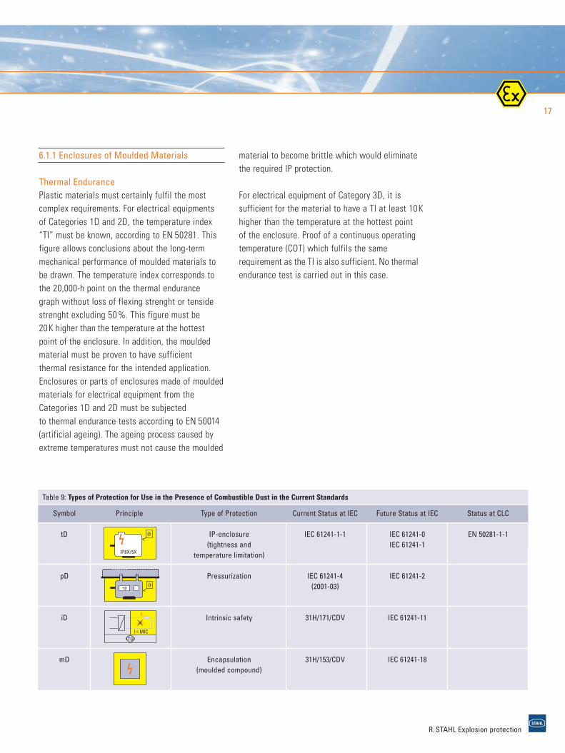
Currently four types of dust ignition protectionexist (see Table 9):
6.1 Type of Protection “tD”
In Europe, this is generally regarded to be the mostimportant method for power engineering equipment.
EN 50281-1-1 defines the type of protection for electrical equipment: “Protection by Enclosure.”Two degrees of dust protection are defined fordust explosion protection: 1. Dust-tight: for the use of equipment in Zone 20,Zone 21 areas and even in Zone 22 areas, in thecase of the presence of conductive dust. 2. Dust-protected: for the use of equipment inZone 22 areas, in the case of the presence ofnon-conductive dust.
The type of protection "tD" requires the limitationof the surface temperature of the enclosure andthe limitation of dust ingress into the enclosure(dust-tight and dust-protected enclosures):
> Dust-tight enclosureAn enclosure which prevents the ingress of allobservable dust particles (IP 6X).This means that a safe area is established inside the enclosure. Please note that as com-bustible dust particles are approx. 20 to 40 µmin size and thus below the gap of flameproofjoints required by EN 50018 for flameproofenclosures. Flameproof enclosures are not inthemselves dust-tight and must be separatelytested and certified according to this condition.
R. STAHL Explosion protection
> Dust-protected enclosureAn enclosure which the ingress of dust is nottotally prevented, but does not enter to interferewith the safe sufficient quantities to operationof the equipment. Dust shall not accumulate in aposition within the enclosure where it is liableto cause an ignition hazard (IP 5X).
The material used for the enclosure is central significant. It must be subjected to specific material tests. Despite the ageing process under-gone by the material and the expected mechanicalstresses, the enclosure must ensure the requireddust protection. Possible materials are:> Metals (such as coated steel, stainless steel,
light metal)> Glass (for enclosure parts, eg. inspection
windows)> Moulded plastic
Metals used for this purpose may have to be sub-jected to an impact test at low temperatures, as some metals (light metals) have less favourablemechanical stress at low temperatures than at higher ones.
In addition, light metal may contain a maximum of 6 % magnesium, as it otherwise tends to formsparks upon impact with materials such as rustyiron. Glass must withstand a thermal shocktest without cracks or without such extensive damagethat it breaks during a subsequent impact test.
6
staubEX_e_04_10_04.qxd 21.10.2004 12:48 Uhr Seite 16
17
R. STAHL Explosion protection
6.1.1 Enclosures of Moulded Materials
Thermal EndurancePlastic materials must certainly fulfil the mostcomplex requirements. For electrical equipmentsof Categories 1D and 2D, the temperature index “TI” must be known, according to EN 50281. Thisfigure allows conclusions about the long-termmechanical performance of moulded materials to be drawn. The temperature index corresponds tothe 20,000-h point on the thermal endurance graph without loss of flexing strenght or tensidestrenght excluding 50 %. This figure must be 20K higher than the temperature at the hottestpoint of the enclosure. In addition, the mouldedmaterial must be proven to have sufficient thermal resistance for the intended application. Enclosures or parts of enclosures made of mouldedmaterials for electrical equipment from theCategories 1D and 2D must be subjected to thermal endurance tests according to EN 50014(artificial ageing). The ageing process caused byextreme temperatures must not cause the moulded
material to become brittle which would eliminatethe required IP protection.
For electrical equipment of Category 3D, it is sufficient for the material to have a TI at least 10Khigher than the temperature at the hottest point of the enclosure. Proof of a continuous operatingtemperature (COT) which fulfils the same requirement as the TI is also sufficient. No thermalendurance test is carried out in this case.
Table 9: Types of Protection for Use in the Presence of Combustible Dust in the Current Standards
Symbol Principle Type of Protection Current Status at IEC Future Status at IEC Status at CLC
tD IP-enclosure IEC 61241-1-1 IEC 61241-0 EN 50281-1-1(tightness and IEC 61241-1
temperature limitation)
pD Pressurization IEC 61241-4 IEC 61241-2(2001-03)
iD Intrinsic safety 31H/171/CDV IEC 61241-11
mD Encapsulation 31H/153/CDV IEC 61241-18(moulded compound)
TGI < MIC
+p
IP6X/5X
staubEX_e_04_10_04.qxd 21.10.2004 12:48 Uhr Seite 17

18
SealsType of protection “protection by enclosures”depends on the elastomeric seals used. These areevaluated in accordance with Annex B3.3 of EN 50014. This is an ageing test using speciallyshaped test objects (ISO 48/ ISO 1818) which teststhe increase in hardness of the material. This figure must not exceed 20 % difference betweenthe initial and the final figure. Materials that have hardened to a greater degree may lose their sealing properties.
Static electricityAn electrostatic discharge is a “very effective” ignition source. When moulded materials is usedfor enclosures, the outer surface must be prevented from becoming charged. Otherwise, oneof the following types of discharge will occur:> Spark discharge
This type of discharges takes place betweengrounded and ungrounded components and isable to ignite all gases and vapours, and almostall dust atmospheres.
> Brush dischargeThis type of discharge is a special form of thecorona discharge. Pipes, elbows, screws, andtools may serve as electrodes at the maximumfield strength. This type of discharge representsno risk to most dusts, but caution is advisedwith regard to gases and vapours.
> Propagating brush dischargeThis is a discharge of a chargeable materialwith a low layer thickness (< 8 mm) on a substratewith adequate conductive.
dust types of protectiondust-explosion protection
Table 10: Summary of Requirements for Electrical Equipment
Requirements: Cat. 1 + 2 – Zone 20+21 Cat. 3 – Zone 22
No dust infiltration in enclosure IP6X IP5X
No dust infiltration IP6X IP5Xat cable entries
Propagating brush discharges Insulation resistance ≤ 10 9 Ωmust be avoided Breakdown voltage ≤ 4 kV
Thickness of insulation ≥ 8 mm
Laser radiation (in accordance with 5 mW/mm2 continuallyEN 50281-1-1) 0.1 mJ/mm2 impulses
Ultrasonic (in accordance with 0.1 W/cm2 / 10 MHz continuousEN 50281-1-1) 2 mJ/cm2 puls
0.1 W/cm2 average
External connection for as in “e” as in “n”equipotential bonding
Plugs, sockets and connectors Separation with no voltage applied except up to 10 A, 250 V; here IP6X sufficient for separation; dust must not fall into opening
Luminaires Light source with cover, lock or warninglabel; no low power sodium lamps
Clearance and creepage IEC 60664 IEC 60664distance of connecting parts
Certification required yes no
Label: CE compliance according to Directive 94 /9 /EC
Conformity to standards
Surface temp. in °C, T … °C T … °C(not temperature class)
R. STAHL Explosion protection
6
staubEX_e_04_10_04.qxd 21.10.2004 12:48 Uhr Seite 18

19
An example: Moulded materials in the pipes of pneumatic conveyor systems initially receives astrong electrostatic charge from friction on theinside. This charge produces an influence-charge onthe external surface, which is coated with plasticmaterial and covered dust. This double layer ofcharge may contain large amounts of energy. Ifone short-circuits both sides of the doubly chargedlayer, all the stored energy is violently discharged.This causes brightly lit discharge channels to form on the surface of the plastic material. Thisdischarge may contain several joules of energy, sothat nearly all gases and vapours and the majorityof dusts will be ignited. However, propagatingbrush discharges are relatively rare in practice.
The following measures can prevent this type ofdischarge process such as these :> Adjusting the surface resistance to 10 9 Ω and
grounding the plastic material.> Limiting the breakdown voltage of the non-
conductive material to 4 kV.> Avoiding thicknesses < 8 mm for the non-conduc-
tive material.> Limiting isolated capacities to < 10 pF.> Increasing humidity to > 65 % in order to reduce
the insulation resistance of non-conductivematerials.
Table 11: Summary of the Requirements for Rotating Electrical Machines, Type of Protection “tD”
Requirements Cat. 2 – Zone 21 Cat. 3 – Zone 22
Dust tightness of enclosure IP6X IP5X
Magnesium content in enclosure material ≤ 6 % ≤ 6 %
Thermal properties of non-metallic as in “e” as in “n”enclosure materials
Insulation resistance of enclosure, ≤ 10 9 Ω ≤ 10 9 Ωfan guards
Insulation resistance of the fan wheel ≤ 10 9 Ω ≤ 10 9 Ωat all speeds
External connection for as in “e” as in “n”equipotential bonding
Dust tightness of entries IP6X IP5X
Degree of protection of the external fan as in “e” as in “e”
Protective cover for V1 (air inlet on top) as in “e”
Fan and cover construction and mounting as in “e” as in “e” /”n”
Clearances in ventilation system as in “e”
Magnesium content in the material ≤ 6 % ≤ 6 %of the fan
Clearance and creepage IEC 60664 IEC 60664distances of connecting parts
Certification by notified body required yes no
CE conformity
Conformity to standards
Surface temperature in °C T …°C T …°C(not temperature class)
R. STAHL Explosion protection
staubEX_e_04_10_04.qxd 21.10.2004 12:48 Uhr Seite 19

Cable GlandsPower supply and instrumentation cables are connected to the explosion-protected electricalequipment. The cable entries must be in accordance with Annex B of EN 50014. This meansthat the certified “Increased safety” cable glandsfor hazardous areas may be used. It must be noted,however, that the Ex e cable entries require IP 54,whereas for dust explosion protection, equipmentsfrom Categories 1D and 2D require IP 6X anddevices from Category 3D IP 5X. In addition, test of increase in hardness is required (see Seals).This verification can be provided by the tests mentioned here or by data sheets from thegasket manufacturer.
6.2 Protection by Pressurization “pD”
This type of protection, based on Pressurizedapparatus “p”, could become important in the protection of switch cabinets in hazardous areas,for example. Equipment of the type “pD” canonly be used in Zone 21 and Zone 22 (not in Zone20). The purging phase required for gas explosionprotection is not permitted for dust explosion protection, as the swirling up of deposited dust could produce a hazardous explosive atmosphere.Section 4.3 of the standard explicitly requires that before the pressurization system is switchedon, the interior of the equipment be cleaned andall dust that accumulated there after switching offthe external ventilation be removed.
The measures to be taken when the pressurizationequipment fails are graduated according to zone and the presence of operational ignitionsources (see Table 12).
Mechanical StabilityFor equipment from Categories 1D and 2D,mechanical tests are carried out in accordancewith EN 50014. The enclosures must withstand animpact energy of 7 joules.
If the enclosure contains light transmitting parts,they are subjected (without basket guard) to a testwith 4 joules or (with basket guard) to one with 2 joules.
Tests such as these are to be carried out afterthermal shock resistance test at a temperature 10 to 15 K higher than the maximum operatingtemperature and 5 to 10 K below the lowest operating temperature.
After the mechanical stability test, the degree of protection IP according to Table 10 has to befulfilled.
In the case of portable electrical equipment, a drop test in accordance with EN 50014 must alsobe carried out.
20
dust types of protection
Table 12: Requirements on Failure of Pressurization
Type of apparatus in the enclosure
Zone operational ignition source no ignition source in normal operation
20 “pD” not applicable “pD” not applicable
21 Switching off as in 7.5.1.1 Warning as in 7.5.1.2
22 Warning as in 7.5.1.2 Internal pressurization not required
R. STAHL Explosion protection
dust-explosion protection6
staubEX_e_04_10_04.qxd 21.10.2004 12:48 Uhr Seite 20
6.3 Intrinsic Safety “iD”
The current draft (CD) largely corresponds to the4th edition of IEC 60079-11: 1999 for gas explosion protected apparatus with type of pro-tection Intrinsic safety “i”.
The final version should refer for the most part to the directly valid sections of Standard IEC 60079-11 without repeating the text of thisstandard. This is what is to be expected in practice when the design of “iD” apparatus isderived from existing and already tested intrinsically safe apparatus.
The preliminary translation of the introduction to the future standard IEC 61241-11 mentions thefollowing basic requirements:> Electrical circuits must fulfil the requirements
of Group IIB from IEC 60079-11, in order to prevent ignitable sparks.
> Normally, degree of protection IP 6X or encap-sulation is required to ensure that clearancesand creepage distances are not effected.
> Power limitation for equipment or their partsthat are not proteced by an enclosure or encapsulation (e.g. for non-insulated sensors).This is the intended to prevent that a dust layer ignites due to a direct transfer of power byconductive dust and to prevent ignition due toheat on the surface of components.
> Temperature limits on all outer surfaces of apparatus or their parts whose power limitsexceed the operational limits required in IEC 61241-11. The surface may consist of anenclosure or an encapsulation.
Work is continuing on the standard for the intrinsicsafety “iD” ignition protection type, therefore we refer the reader to current articles in our Ex-Magazine.
6.4 Encapsulation “mD”
The dust type of protection “mD” in accordancewith IEC 61241-18 is to be based primarily on typeof protection “m” according to IEC 60079-18,which is currently being revised.
Further proceedings on the draft of IEC 61241-18will therefore be determined by the developmentof the new IEC 60079-18.
21
R. STAHL Explosion protection
staubEX_e_04_10_04.qxd 21.10.2004 12:48 Uhr Seite 21

equipment selection22
7. Equipment Selection
After assessment of the installation and its possible risk, the user should consider the following criteria when selecting electricalequipment:> Determination of the equipment category in
accordance with the hazardous zone.> Assessment of the properties of existing dust.> Maximum permissible surface temperature of
the equipment, taking into consideration the type of dust, the ignition temperature of the dust cloud and, if dust deposits cannot beexcluded, the ignition temperature of the dust layer.
The selection of the equipment category can be carried out as described in Table 13. This defines the design of the enclosure in accordance with the requirements of Clause 4,5 and 6 of EN 50281-1-1. The dust-tightness tested using theprocedure described in EN 60529 for Category 1D,must be taken into account.
R. STAHL Explosion protection
The “Essential Health and Safety Requirements”from Directive 94/9/EC deal with the problem ofdust deposits in Annex II, Paragraph 1.2.4. In addition to requiring the removal of dust layers,this states that the surface temperature of equipment and equipment parts be well below the ignition temperature of the dust layer. An accumulation of heat must be expected andshould be countered with using temperaturelimitation. Dust accumulations should, if possible,be limited or avoided entirely. For the equipmentmanufacturer, this means the equipment must beproduced in such a way that dust deposits do notarise and/or the equipment is easy to clean.
> EN 50281-1-2 deals wih the selection of electrical equipment and specifies that independent of classification into zones, thepossibility of the equipment being covered or completely submerged by dust must be takeninto consideration, unless this situation can be avoided.
> EN 50281 does not currently regulate thequestion of how dust deposits on electrical equipment influence the safety level. For equip-ment from Category 3D, there is no requisiteconsideration of possible faults. This wouldmean that equipment from Category 3D wouldbe subject to a thermal assessment – in ex-treme cases when totally submerged in dust –however that common faults need not be taken into consideration.
Zone 21 presents a similar problem. Is the inside of containers in which combustible dust isstored also a part of this zone? The situation is clearer in the case of Zone 20, as due to thedefinition complete sumerging of the equipmentmust be taken into account.
Table 13: Selection of Dust Explosion Protected Apparatus
Type of Dust Zone 20 Zone 21 Zone 22
conductive Category 1D Category 1D Category 1DTemperature limitation or 2D or 2Dwhen excessive deposits can be present
non-conductive Category 1D Category 1D Category 1D,Temperature limitation or 2D 2D or 3Dwhen excessive deposits can be precent
dust-explosion protection7
staubEX_e_04_10_04.qxd 21.10.2004 12:48 Uhr Seite 22

23
R. STAHL Explosion protection
The self-ignition of dust deposits is a critical problem. These processes are often caused byexothermal reactions involving oxygen from the surrounding air. It could be a chemical reaction(oxidation), a physical reaction (adsorbtion) or adecomposition process (mainly in the case oforganic dusts). Self-ignition is determined of thetemperature of the surrounding area, of the geometric factors and of the volume of the dust.The reaction heat produced during decompositionof materials can produce carbonisation gas, whichin turn can lead to an explosive gas/air mixture.
Not every case of dust ignition necessarily leads to an explosion. Dusts with low rate of pressure rise may first of all be a dust fire. Under certainconditions, an explosion may occur, often in a completely different location than the ignition.The fire can spread from the place of origin to
other areas by way of transportation facilities.During this process, the flames swirl up unburneddust, which in turn takes deposited dust with it. A sudden change in the volume of the dust cloud as it enters a larger room (e.g. a silo) can producea hazardous explosive atmosphere. The flamescause ignition.
The ignition temperature of a dust layer isdetermined using the method from EN 50281-1-2.The determination of the maximum surfacetemperature that an electrical apparatus canachieve must be done by the manufacturer, withany possible faults taken into consideration.Temperature limitation measures should be usedto counter these faults (electrical/thermal fuse).The maximum surface temperature is measured as specified in Clause 10 of EN 50281-1-1.
Figure 7: Correlation between the Maximum Permissible Surface Temperature and the Thickness of Dust Layers
staubEX_e_04_10_04.qxd 21.10.2004 12:48 Uhr Seite 23

24
When determining the maximum permissiblesurface temperature (in relation to the surrounding dust), two figures should be noted:1. Maximum permissible surface temperature
when a dust cloud is present (calculation in accordance with 6.1 of EN 50281-1-2). The ignition temperature of the dust cloud must be taken into account.
2. Maximum permissible surface temperature when a dust layer is present. When making the determination, one must take the ignitiontemperature of a dust layer (which is dependenton the thickness of the dust layer) into account:
> For dust deposits up to 5 mm thick, the calculation must be made in accordance with6.2.1 of EN 50281-1-2.
> For dust deposits > 5 mm--50 mm, the curvesin Figure 7 may be applied. The redutions in temperature plotted here weredetermined empirically for dust layers of up to 50 mm on top of electrical equipment. The curves take into account both the reduction,specific to dusts, of the ignition temperaturewith increasing layer thickness, and also an ex-pected increase of the temperature of the electronic apparatus, due to the reduction of theheat flow. In addition, the curves include theusual safety reduction of 75 K.Here it must be stated explicitly that this doesnot take into account an electrical apparatussubmerged completely in dust.
> Determining a surface temperature for dust deposits > 50 mm: According to the currently valid requirements in Clause 6.3 of EN 50281-1-1, if dust deposits of excessive thickness are present, the equipment in question must be tested in a laboratory usingthe relevant dust (see Annex A of the above-mentioned standard).
L
LL
L
L
equipment selection
R. STAHL Explosion protection
Figure 8: Determining the Maximum Surface TemperatureTL Under a Dust Layer of Thickness L in mm
dust-explosion protection7
staubEX_e_04_10_04.qxd 21.10.2004 12:48 Uhr Seite 24
25
In the future, manufacturers will have the option,during the type testing, of determining a surfacetemperature TL under a deposit of thickness L (orientated toward the thickness of the layerduring actual use), which may be stated onlabels (Figure 8). Section 5.2 of IEC 61241-0 states: “In addition to the maximum surfacetemperature TL required in 5.1, the maximum surface temperature may be stated for a givendepth of layer, TL, of dust surrounding all sidesof the apparatus, unless otherwise specified in the documentation, and marked according to29.2(8)”. For the determination of the temperatureTL, 23.4.5.2 requires: “…the electrical apparatus to be tested shall be mounted andsurrounded by a layer depth "L" as stated by themanufacturers specification. The measurementfor the maximum surface temperature shall be made …using a dust having a thermal con-ductivity of no more than 0.003 kcal/m ·°C · h.”The user must take note of Clause 6.3.3.4 of the installation standard 61241-14: “Where theapparatus is marked TL for a layer depth theignition temperature of the combustible dust, ata layer depth L, must be applied in place of T5mm.”
The following verification from 1 and 2 mustbe made by the user!
The maximum permissible surface temperature,in relation to the ignition temperature of a dustcloud Tic and/or the ignition temperature of a dust layer Til of the surrounding dust is determinedas follows: 1. Maximum permissible surface temperature in
case of dust clouds Tmax = 2/3 Tic
2. Maximum permissible surface temperature in case of dust layers (5 mm thickness)Tmax = Til – 75 K
Example: flourTic ≥ 380°C and Til ≥ 300°CTmax (1) = 2/3 x 380°C = 253°CTmax (2) = 300°C – 75 K = 225°C
Accordingly, the surface temperature of the electrical equipment in this particular case mustnot exceed the value of 225°C; this must be guaranteed by the manufacturer (see “Determi-nation of the Maximum Surface Temperature”above).
R. STAHL Explosion protection
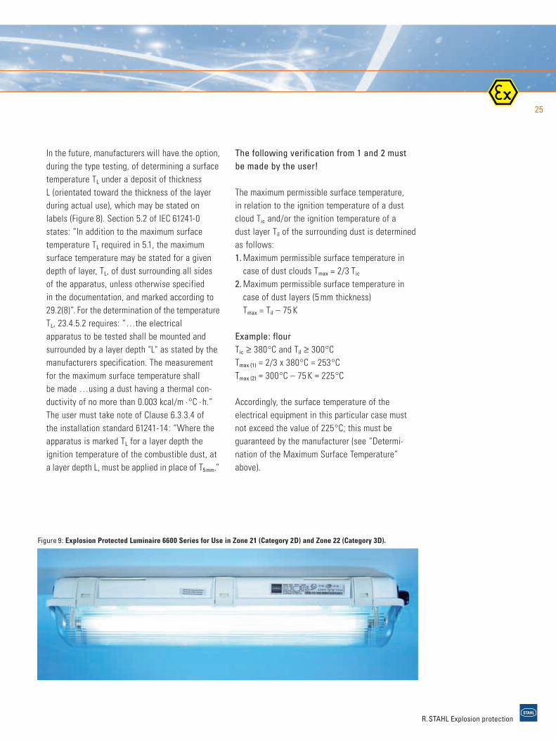
Figure 9: Explosion Protected Luminaire 6600 Series for Use in Zone 21 (Category 2D) and Zone 22 (Category 3D).
staubEX_e_04_10_04.qxd 21.10.2004 12:48 Uhr Seite 25

26
Plugs and Sockets, Plug ConnectorsIn Zone 20, plugs and sockets are not permitted. In Zone 21 and Zone 22, for electrical equipment from Categories 2D and 3D, the following require-ments apply: > Plugs and sockets shall either be interlocked
mechanically, or electrically, or otherwise designed so that they can not be separatedwhen the contacts are energized or in such away that they can only be separated when thepower is off, or
> In accordance with 9.2 of EN 50014, plug connectors must be fixed together by special fasteners and a warning label affixed to them:“DO NOT SEPARATE WHEN ENERGIZED”.
Supplementary RequirementsEN 50281-1-1 contains several supplementaryrequirements for specific electrical equipmentfrom Category 2D which must be taken intoaccount. Here are some important examples:> Rotating electrical machines, such as shaft
driven external fans used for cooling, must besurrounded by a fan hood.
> Switch gear with contacts immersed in flam-mable dielectrics is not permitted. Enclosuresmust be locked with isolators or labeled with awarning lable:“DO NOT OPEN WHEN ENERGIZED”,if contactors or other remote-controlled com-ponents are included in them. If a disconnectoris built-in, it must disconnect all poles and beset up so that its contact position is visible, ortheir position is reliably indicated. Any interlockbetween such disconnector and the cover or door shall only permit the door to be openedwhen the separation of the disconnector contacts are effective.
Additional internal supplementary enclosures for parts which remain energized when the enclosure is opened.
equipment selection
R. STAHL Explosion protection
Radiation-Emitting EquipmentOptical radiation is a peripheral phenomenon inthe field of dust explosion protection. The firstfactor to be considered when determining the limitvalue is: How high is the power density?
If the power density is ≤ 0.1 W/cm2, no furtherassessment is necessary. Pulse-shaped signals areassessed according to the energy density. In addition, however, the energy density as an averageof the pulse-pause ratio must be taken intoaccount. Besides this, an assessment of possiblefaults is to be carried out in order not to exceed thelimit values for equipment from Categories 1D and 2D. The figure for the pulse-pause ratio, whichis the basis of the calculation, is particulary im- portant. Radiation in the optical range (especiallyif it is focussed) may ignite the dust/air mixture. Laser radiation can cause ignition from a great distance, even when it is not focussed.
Limit values to be ensured:> Power density ≤ 5 mW/mm2 for
continuous wave lasers> Pulse energy density ≤ 0.1 mJ/mm2 for
pulsed lasers
In the case of ultrasonic transmitting (e.g. sensors), a large percentage of the energyemitted by the ultrasonic transducer is absorbedby dust. This causes heating of the dust particles, which in extreme cases even reach the ignition temperature. Limit values to be observed: > Power density ≤ 0.1 W/cm2
> Pulse energy density ≤ 2m J/cm2
dust-explosion protection7
staubEX_e_04_10_04.qxd 21.10.2004 14:26 Uhr Seite 26

27
> Fuses: unopenable when energized, or warning label as for switch gears.
> Luminaires: lamps containing free metallicsodium (e.g. low-pressure lamps according toEN 60192) are not permitted.
Connecting ComponentsAs in gas explosion protected areas, electricalequipment is connected to the outer power circuitusing terminals.
The equipment can also be connected using a cable that is fixed integrated. Apparatus withfixed connected cables are an exception whenonly one end of the cable is permanently connected. These devices must be labeled withthe symbol X. The user must be given instructions for the unattached end of the cable (e.g. within Zone 21,the free cable end must be plugged into an apparatus of Category 2D).
Operating Instructions and MarkingTable 15 shows the marking for electrical equipmentin accordance with EN 50281 and Directive94/9/EC. Data relevant to explosion protection,such as equipment group, category and maximumsurface temperature should be displayed as shownin the following example: II 2 D T 135 °C.
No classification of dusts into temperature classes is planned. Unlike gases, dusts require amargin of safety between surface temperature andignition temperature of a dust cloud and a dust layer.
Each equipment has a set of operating instructions which must contain the elementsshown in Table 14.
R. STAHL Explosion protection
Table 14: Contents of Operating Instructions
According to EN 50281-1-1
> Putting into service
> Use
> Assembling and dismantling
> Maintenance
> Installation
> Electrical characteristics
> Specific conditions
Table 15: Marking of Equipment
EN according to EN 50281-1-1
> Name and address of manufacturer(trademark)
> Series and type identification
> Serial number
> Electrical characteristics
> Maximum surface temp.T
>
> Equipment Group, in this case II
> “D” for dust
> Category
> Testing laboratory and certification number(year/ Id. number.)
> Year of manufacture
>
staubEX_e_04_10_04.qxd 21.10.2004 12:48 Uhr Seite 27
installation and maintenance28
dust-explosion protection
8. Installation and Maintenance
The protective measures described in Section 4alone are not sufficient to prevent an explosion.Installation carried out according to requirements,punctual, correct and consistent maintenance are all crucial for maintaining safe operations (EN 50281-1-2).
During installation, the manufacturer’s operation conditions in the operating instructionsmust be followed carefully.
8.1 Installation of Cables
Selection of Cables In general, the common types of cables arepermitted, if they are installed into screwed, solid,drawn or steamed welded conduits. Cables whoseconstruction ensure that they are dustproof andsuitable for mechanical stress may also be used.Examples are: > Cables with thermoplastic or elastomeric wire
insulation, screened or armoured cable and anouter sheath of PVC (poly-vinylchloride), PCP(polychloroprene rubber), or a similar material.
> Cables with a seamless aluminium sheath withor without armouring.
> Mineral-insulated cables with metal sheath.Note: These cables and wires may have tobe operated below their rated valuues to limit thesurface temperature from exceeding the required values. > When cables are externally provided with
protection, or when there is no danger of me-chanical damage, cables with thermoplastic or elastomeric insulation and a sheath of PVC, PCP, or a similar material are permitted.
Cabel installation> Cables must be placed so that they cannot
become electrostatically charged by moving dust(friction effect).
> Cables runs shall be arranged insofar possiblethat no large dust deposits can be collected.Sufficient access for cleaning must be possible.
> If possible, cables shall not pass through areaswith potentially explosive dust atmosphere ifthey are not connected to this area.
> If dust layers form on cables, preventing free aircirculation, a reduction of the current carryingcapacity of the cable shall be considered. This applies especially to dusts with a low ignition temperature.
> If cables pass through walls or other structures,this must be done so as to prevent the passageor collection of combustible dust.
> For transportable electrical equipment, a suitable cable type must be used. For these purposes, often a suitable connection box must be placed between the moving and fixed cable routing.
> If metal conduit is used, care should be taken to ensure that there is no possibility of cabel damage at the connecting points, that the connecting points are dustproof, that the im-permeability of the connected equipment is notreduced, that the connecting points are includedin the potential equalisation.
R. STAHL Explosion protection
8
staubEX_e_04_10_04.qxd 21.10.2004 12:48 Uhr Seite 28
29
Cable GlandsThe requirements for the entries into dust explosion protected equipment from Categories 1Dand 2D are almost identical with those for a gas explosion protected glands, type of protection“Increased safety”. Both must be in compliancewith Annex B of EN 50014.
The only differences are in the degree of protection and in approval:> Dust-Ex: IP 6X, certification for Zone 20 and/or
Zone 21> EEx e: IP 54, certification for Zone 1 and Zone 2
Cable glands must be assembled and mounted sothat they do not compromise the equipment’s dusttightness. They can also be permanently connected to the equipment, in which case theyare certified together with the equipment.
8.2 Maintenance and Servicing
In addition to the protective measures alreadytaken, an organisational plan must be drawn upfor the installation. > Cleaning, removal of dust deposits.> Inspection and maintenance of equipment and
protective systems.> Testing of earthing, especially for the
parts of the equipment that could become electrostatically charged.
These measures serve firstly to reduce the risk of explosion and secondly to ensure the effective-ness of the constructional protective measures.
“The inspection and maintenance of electricalapparatus for use in combustible dust shall only becarried out by personnel who are familiar with the concept of protection.” (EN 50281-1-2:1998,12.1)
8.3 Documentation
EN 50281-1-2, 10.3:“Plans of each site shall be maintained to showthe following:> The classification and extent of the
hazardous areas; the information shall includethe zoning and maximum layer thickness, ifgreater than 5 mm.
> Records of the types and marking details of protected apparatus and sufficient informationto enable them to be maintained properly.
> Types, routes and details of wiring system.”
This task is in conformity with the requirement of the Directive 99/92/EC, which obligates the employer to draw up an explosion protection document. The content of the document should indicate:> The explosion risk have been determined
and assessed.> Adequate measures will be taken.> Work equipment and warning device are
design, operated and maintained with dueregard for safety.
> Provisions to ensure that the equipment is used correctly.
R. STAHL Explosion protection
staubEX_e_04_10_04.qxd 21.10.2004 12:48 Uhr Seite 29

product overview30
dust-explosion protection
R. STAHL Explosion protection
9. Product Overview
R. STAHL has a fully certified product range for dust hazardous areas in your installation. We take dust explosion protection just as seriouslyas gas explosion protection. We can offer you aspecially adapted solution for almost every application. At a minimum, all dust explosion protection products comply with the regulations ofGroup 3D; that is, they can be used in Zone 22(non-conductive dusts).
The following equipment series and systems arecertified for both Zone 21 and Zone 22:> Luminaire Series 6600 and 6608,
Compact Luminaire 6100 and 6108> Tank Inspection Light 6122 and
Optical Beacon 6161> Traffic Light 6091> Control System ConSig 8040> Position Switches 8060 and 8070> Junction and Terminal Boxes Series 8118> Control Panel and Terminal Boxes Series 8146
and 8125> Ex d Enclosure System CUBEx> Safety Barriers INTRINSPAK> Isolators Series IS pac> Remote I/O System I.S.1> SolConeX Plugs and Sockets
Some Examples of Dust Explosion
Protected Products
ECOLUX 6608Emergency Luminaire
Optical Beacon 6161Traffic Light 6091
Control System Series 8040
Lighting and Heating Panel Series 8146
Switch- and Distribution Board
CUBEx
Safety BarriersINTRINSPAK
EX i Isolators IS pac
Remote I/O System I.S.1Plugs and Sockets
SolConeX
9
staubEX_e_04_10_04.qxd 21.10.2004 12:48 Uhr Seite 30

31
R. STAHL Explosion protection
Your Safety – Our Reality
If your installation is faced with the risk of a dustexplosion, R. STAHL offers the expertise you need.
R. STAHL has decades of experience in the field ofelectrical explosion protection.
We will be glad to help you solve your safetyproblems. In addition to a comprehensive range ofelectrical equipment, we offer you expert adviceand training in the dust explosion protection field.
Get in touch with us.
You will find a downloadable list of our dustexplosion protection products in PDF form at :
www.dust-ex.stahl.de
staubEX_e_04_10_04.qxd 21.10.2004 12:49 Uhr Seite 31
R. STAHL Schaltgeräte GmbHAm Bahnhof 30, 74638 Waldenburg, GermanyPhone +49 7942 943-0 Fax +49 7942 943-4333
www.stahl.de
VISU
ELL,
Stut
tgar
t
ID-NR. 00 006 84 77 0S-PB-dustex-00-en-04/2004 · Printed in the Federal Republic of Germany
staubEX_e_04_10_04.qxd 21.10.2004 12:49 Uhr Seite 32