duti - dtic
TRANSCRIPT

I
AD-A278 099 AD
REPORT NO T94-10
NUMERICAL MODEL OF THE THERMAL BEHAVIOR OF ANEXTREMITY IN A COLD ENVIRONMENT INCLUDING
COUNTER-CURRENT HEAT EXCHANGE BETWEEN THEBLOOD VESSELS
U S ARMY RESEARCH INSTITUTEOF
ENVIRONMENTAL MEDICINENatick, Massachusetts . •
DUTI
MARCH 1994 S D
'\r i294-a11 040
MCl• QUAL IMPEC-Tis
Appreved 10t p-bl{c velee.e disflvbfi ,.ilmlted,
UNITED STATES ARMYMEDICAL RESEARCH g DEVELOPMENT COMMAND
V4 4 1l -1-4

form• ACýýrc'ý
REPORT DOCUMENTATION PAGE OW N -j2016
1. AGENCY USE ON.y (Leav'e blanK) 0. 3 BePCD;T .TYPE-ý- DA7L$ COVERED
4.TITLE AND U.BT7ITLE 5. FUNDING NUMBERSNume M ell of the Thermal Behavior of an Extremity in a
Cold Environment Including Counter-Current Heat ExchangeBetween the Blood Vessels
6 AUTHOR(S)Avraham Shitzer, Leander A. Stroschein, Paul Vital,Richard R. Gonzalez, Kent B. Pandolf
7. PERFORMING ORGANIZATION NAME(S) AND ADDRESS(ES) 8. PERFORMAF.G ORGAN:ZATION
U.S. Army Research Institute of Environmental Medicine REPORT NUMBER
Natick, MA, 01760-5007
9. SPONSORING MONITORING AGENCY NAME(S) AND ADDRESS(ES) 10 SPONSORING MONITORNGAGENCY REPORT NUMBER
11. SUPPLEMENTARY NOTES
Approved for public release; distribution unlimited
12a. DISTRIBUTION AVAILABIL!TY STATEMENT 12b. DISTRIBUTION CODE
13. ABSTRACT (Maxvrru"'200Cwoos)
A numerical model of the thermal behavior of an extremity, e.g., finger, is presented. The model includes theeffects of: (a) heat conduction (b) metabolic heat generation, (c) heat transport by blood perfusion, (d) heatexchange between the tissue and the large blood vessels, and, (e) arterio-venous heat exchange. Heat exchangewith the environment through a layer of thermal insulation, depicted by thermal handwear is also considered. Thetissue is subdivided into four concentric layers. The layers described, from the center outward, as core, muscle,fat and skin. Differential heat balance equations are formulated for the tissue and the major artery and the majorvein. These coupled equations are solved numerically by the alternating direction method employing a Thomasalgorithm. The numerical scheme was tested extensively for stability and convergence. Results of theconvergence tests are presented and discussed and the dependence on the number of grid points isdemonstrated. Plots of tissue and blood temperatures along selected nodes of the model are shown for differentcombinatio.., of parameters. The effect of counter-current heat exchange between the artery and the vein on thethermal balance of the extremity is presented. This shows clearly the conservation of energy achieved due tothis mechanism. The report is concluded by considering the effects of cold induced vasodilatation on tissuetemperature cycling.
14. SUBJECT TERMS numerical model, physiological model, extremity model, counter- 15. NUMBER OF PAGES
current, heat exchange, blood profusion, heat conduction, cold induced vasodilation, 16. PRICE CODE
heat balance, alternating direction method, Thomas algorithm, thermal insulation, cold
17. SECURITY CLASSIFICATION 18. SECURITY CLASSIFICATION 19. SECURITY CLPS•IFICATION 20. LIMITATION OF ABSTRACTOF REPORT OF THIS PAGE OF ABSTRACT
Unclassified Unclassified Unclassified ULNSN 75-:0-0'-280-5500 S'ar'aac - c''c 298 '•e. 2-89)
2-1 ' :-3b -N I 2
i1
NUMERICAL MODEL OF THE THERMAL BEHAVIOROF AN EXTREMITY IN A COLD ENVIRONMENT
INCLUDING COUNTER-CURRENT HEATEXCHANGE BETWEEN THE BLOOD VESSELS
by
Avraham Shitzer, Leander A. Stroschein, Paul Vital,Richard R. Gonzalez and Kent B. Pandolf
NTIS CRA&UTiC TABUnannouncedJustiication
BYDistrIbution I
Avaiabity Codes
Dist Avan.r
D?2C 4qu"i4.y L 4

TABLE OF CONTENTS
LIST O F FIG URES ............................................ - iii -
LIST O F TABLES ............................................. .v -
ACKNOW LEDGEMENT ......................................... - vi -
INTRODUCTION ...............................................- 1 -
ANALYSIS .................................................. - 2 -
PHYSICAL AND PHYSIOLOGICAL PARAMETERS .................... - 17 -
TESTING OF THE NUMERICAL CODE ............................ - 20 -
RESULTS AND DISCUSSION ................................... - 27 -
REFERENCES ............................................... - 37 -
GLO SSARY ................................................ - 40 -VARIABLES ........................................... - 40 -
GREEK LETTERS ....................................... - 42 -
SUPERSCRIPTS ........................................ - 42 -
SUBSCRIPTS .......................................... - 42 -
APPENDIX A - Derivation of the equations for the various matrix nodal points. - Al -Center i-node; regular j-node ............................... - Al -External i-node; regular j-node .............................. - A3 -
Interface i-node; regular j-node .............................. -A6 -
End j-node; regular i-node ................................. - A8 -
End j-node; external i-node ............................... - Al1 -End j-node; center i-node ................................. - Al1 -End j-node; interface i-node ............................... - A13 -
APPENDIX B - Heat transfer coefficients for the major blood vessels ....... - B1 -
APPENDIX C - Program source code listing and operating instructions ...... - Cl -
Program Environment .................................... - Cl -Description of program Units ............................... - C2 -
UNIT FINGER93.PAS { main program ) ................ - C2 -
-i-

UNIT VARSP.PAS ................................. - C2 -UNIT TISUESP.PAS ............................... - C3 -UNIT PHYSSP.PAS ................................ - C4 -
OUTPUT FILES ........................................ - C5 -OVERVIEW OF PROGRAM OPERATION ...................... - C5 -Running the Program ..................................... .- C8 -PROGRAM SOURCE CODE LISTINGS ...................... - Cli -
1. FINGER93.PAS .............................. - Cll -2. VARSP.PAS ............................... - C20 -3. TISUESP.PAS .............................. .- C27 -4. PHYSSP.PAS .............................. .- C42 -
APPENDIX D - DISTRIBUTION LIST .............................. - Dl -
- ii -

LIST OF FIGURES
1. Schematic diagram of the cylindrical model of an extremity ............. 3
2. Cross section through the cylindrical model showing the four radial tissuecom partm ents .............................................. 8
3. Cross section of a typical control volume of the cylindrical model ......... 9
4. Comparison of temperature distributions along the finger model calculated by ananalytical model [20] and the present model ....................... 22
5. Ratios of steady-state heat flow in vs. heat flow out as affected by the number ofdivisions in the axial direction .................................. 26
6. Steady state temperature distributions of the exernal surface of the finger modelas affected by the number of divisions in the axial direction ............ 26
7. Steady state temperature distributions of a bare finger in still air for basal andnutritional blood flows ....................................... 28
8. Steady state temperature distributions of a gloved finger in still air for basal andnutritional blood flows ....................................... 29
9. Steady state temperature distributions of a bare finger in windy air for basal andnutritional blood flows ....................................... 30
10. Steady state temperature distributions of a gloved finger in windy air for basal andnutritional blood flows ....................................... 31
11. Temperature variations on the dorsal tip of the bare and gloved finger model withnutritional blood flow for still and windy air ......................... 32
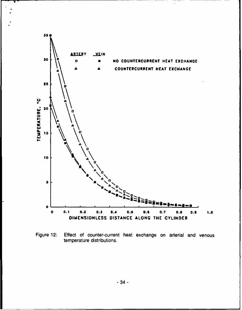
12. Effect of counter-current heat exchange on arterial and venous temperaturedistributions .............................................. 34
13. Dorsal temperature variations at the tip and middle of the finger model for coldinduced vasodilatation ....................................... 35
- iii -

Al. Identification of nodal points in the numerical grid .................. A2
A2. Schematic diagram of the center node .......................... A4
A3. Schematic diagram of the external-regular node ................... A5
A4. Schematic diagram of the interface node ......................... A7
A5. Schematic diagram of the end j - regular i node .................... A9
A6. Schematic diagram of the end j - external i node ................... A12
BI. Schematic representation of an "influence" volume enclosing a major bloodvessel .................................................. B 2
B2. Schematic diagram of an artery-vein pair ........................ B4
-iv -
LIST OF TABLES
1. Coefficients of the radial-direction [AQ matrix ....................... 13
2. Coefficients of the axial-direction [Aj matrix ....................... 14
3. Coefficients of the {S) vector .................................. 15
4. Property values used in the numerical computations ................. 19
5. Heat transfer coefficients for combinations of wind conditions for a bare and glovedfing e r . . . . . . . . . . . . . . . . . . . . . . . . . . . . . . . . . . . . . . . . . . . . . . . . . . . 2 1
6. Parameters used in the numerical computations .................... 25
- V "

ACKNOWLEDGEMENT
The authors wish to acknowledge the expert help provided by Ms. Laurie A.Blanchard, Sgt. Julio Gonzalez and Ms. Deborah A. Toyota. This work was carried outwhile the senior author held a Senior NRC Research Associateship at USARIEM.
- vi -

INTRODUCTION
Heat exchange between the human and the environment has always been a topic ofgreat interest as this is one of the essential manifestations of homeothermy. This interest hasintensified over the past few decades as the understanding of the mechanisms involved arespurred on by human's venturing into extreme environments, e.g., outer space. Even lessextreme environments may pose life threatening challenges to humans and the literature isladen with examples of both heat, [1] and cold, [2] related casualties.
Physiological studies, in which human subjects are exposed to extreme environmentalconditions are essential for collecting data on the actual thermal behavior of men andwomen. These studies are employed to generate detailed and reliable databases and to testthermoregulation theories. Much information may also be gained by formulating models whichsitiwi.ate qualitatively the thermal behavior of the human body. The chief advantage of thesemodels is their ability to predict and point out trends and limitations while avoiding thedangers and cost involved in actually performing, time consuming and sometimes hazardousexperiments. Their inherent disadvantage resides in the necessity to verify their predictions.A variety of models simulating human thermal behavior have been developed. These rangefrom models of single organs, e.g., [3-5] to models of the entire body, e.g., [6-9].
In this report a detailed model of an extremity exposed to cold weather is developed.The reasons for choosing an extremity are two-fold: (a) a model of an extremity may serveas a "building block" for other elements, and, (b) the extremities are usually the mostvulnerable body elements particularly in cases involving operations in cold weather.
The extremity is depicted as a right-angle cylinder in which heat flows in both theradial and axial directions. Around the entire external surface of the cylinder different layersof insulation may be applied through which heat is exchanged with the environment. Heat isalso exchanged internally by conduction and with the blood flowing both in the major bloodvessels and in the vessels of the capillary bed, Counter-current heat exchange between themajor blood vessels is also taken into account.
The model is presented as a consistent set of energy balance equations and is solvedby a finite-difference, alternating directions numerical scheme employing the Thomasalgorithm. This scheme has been tested extensivnly for stability, convergence and accuracy.It was also run for a number of cases to demonstrate its fundamental capabilities.
- 1 -

ANALYSIS
Energy balance in a right - angle circular cylinder depicted in Fig. 1 is expressed by:
a* k - ar* ar as, '
Wb C(T8 - TO ) + u.(T - T*) + u1(T -
where the term on the left hand-side represents the rate of change of stored energy and theterms on the right hand-side express radial and axial heat conduction, metabolic heatgeneration rate, heat exchange with the capillary bed and heat exchange with a large arteryand a large vein, respectively. All properties and variables are defined in the Glossary andasterisks indicate dimensional variables.
The following boundary and initial conditions are specified for the problem:
At the center of the cylinder an adiabatic condition is formulated to satisfy symmetryrequirements:
- o 0z*0= (2)
On the outer circumferential surface of the cylinder heat is exchanged with the environmentby convection:
aT' _h(T"- T') * 1=R (3)
At the base of the cylinder a variable temperature is assumed:
2*= ,('*) z'=* = o (4)
-2-

THERMAL INSULATION
ARTERY
VEIN
Figure 1: Schematic diagram of the cylindrical model of an extremity
-3-
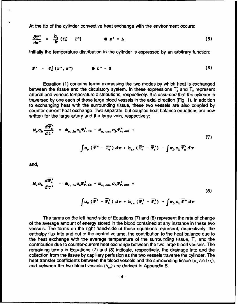
At the tip of the cylinder convective heat exchange with the environment occurs:
, = - ) -"T. = L(k (5)
Initially the temperature distribution in the cylinder is expressed by an arbitrary function:
T* = T' (r*, zs) 0 V = (6)
Equation (1) contains terms expressing the two modes by which heat is exchangedbetween the tissue and the circulatory system. In these expressions T., and T, representarterial and venous temperature distributions, respectively. It is assumed that the cylinder istraversed by one each of these large blood vessels in the axial direction (Fig. 1). In additionto exchanging heat with the surrounding tissue, these two vessels are also coupled bycounter-current heat exchange. Two separate, but coupled heat balance equations are nowwritten for the large artery and the large vein, respectively:
a cb - 0sa, In 000# n As out Cb 2rvout; +dtr*
(7)
f um(T T) dv + h,,, fT~ 2)fwb cb F*d v
and,
MCb - lil. - ., out CbTv, ou +
(8)
fUv(, ;d v+ h,,,:T; +fvb c d v
The terms on the left hand-side of Equations (7) and (8) represent the rate of changeof the average amount of energy stored in the blood contained at any instance in these twovessels. The terms on the right hand-side of these equations represent, respectively, theenthalpy flux into and out of the control volume, the contribution to the heat balance due tothe heat exchange with the average temperature of the surrounding tissue, r', and thecontribution due to counter-current heat exchange between the two large blood vessels. Theremaining terms in Equations (7) and (8) indicate, respectively, the drainage into and thecollection from the tissue by capillary perfusion as the two vessels traverse the cylinder. Theheat transfer coefficients between the blood vessels and the surrounding tissue (u, and uj),and between the two blood vessels (h.,) are derived in Appendix B.
-4-

Two additional mass conservation equations are required for both large blood vessels:
A = 1 . .out + fWb V (9)
and,
w= m,,, fbdv (10)
Prior to applying a numerical solution to the coupled Equations (1), (7) and (8), subjectto boundary and initial conditions (2)-(6), these equations are rewritten in dimensionlessforms:
-r 1 + 1 a22b £r a(r a: 82 a 2 (11)
+ [q + (W+ U') (Tr - !,) + U,,(T, T) ]
d2 _ R2 [ CdrV elaIn bre,in m .,atut b a,aut (12
(12)
f .( )dv + h.e ( ,, - a) f wb~bF.dvJ
d2, R 2 [zh, ,fC Tv In-*,otO Tvot +d - MV Cb abb n vaubva
(13)
fUv (F - F) dv+ h., (F. F) + fwb obhidv]
@1= 0 0 (14)
= B(TO - !P) @1=1 (15)ar
-5-

2' = 2' 1 (t) z= 0 (16)
--= B(o 2-T) *z= (17)YZ
2= T(,z) 0 t 0= (18)
where,
_ *o (19)R
Z" (20)
T -
L
f=b t * (21)R 2
2 -* (22)Temp
Z) = ( -b (23)
_ _ _b_ (24)p 0
_ "___2 (25)q - ezlpkb
W - V'b -R2 (26)kb
"-6-

us a,,Vb=(27)
B1 h-R (28)k
and,
B. 1 h1-z, (29)k
A finite-difference solution is formulated for the above set of dimensionless equations.The cylinder is divided into four radial compartments depicting the core, muscle, fat and skin,respectively, as shown in Fig. 2. Each of these compartments, the boundaries of which aredetermined by anatomical and anthropometric considerations, may be further subdividedradially according to the required details of the temperature variations in the cylinder. Axialdivisions are uniformly spaced. A cross section of a typical control volume is shown in Fig.3.
As a first step in the numerical solution , Equation (11) is multiplied by a hollowcylindrical volume element of thickness dr and length dz and integrated:
-rLa r.A drd =a+a LTf f jS --- 2 jZ-2irSý _Ar 'Z Z a2 z
2--- r--- ,,--2 (30)
.[q+ (W+ UM) (Te - T) + , (T,-)] }Zdrds
The temporal derivative on the left hand-side of Equation (30) is calculated by aforward difference. In evaluating this derivative, a half time step is assumed to facilitate asolution of this two-dimensional problem by the method of alternating directions [10]. In thismethod the solution of the resulting set of difference equations is performed in two half timesteps: first the temperatures in one direction, e.g., radial, are calculated for the first half timestep, based on the values of the temperatures at the current time in the other direction. Next,the temperatures at the other direction, e.g., axial, are evaluated for the next half time stepbased on the values obtained for the first spatial direction in the first half time step. Thiscompletes a full time step, and these values are used to initiate the next full time-stepiteration.
-7-

MUSCLE -
FATSKIN
Figure 2: Cross section through the cylindrical model showing the four radialtissue compartments
-8-

FAT-SKINSKIN SURFACE /INTERFACE
MUSCLE-FAT__INTERFACE
R CORE-MUSCLEINTERFACE
_________I. CYLINDERAz CENTERLINE
Figure 3: Cross section of a typical control volume of the cylindrical model
"-9--

* Accordingly, the integration of Equation (30) yields:
n+ 1ATi; t, j ryA~z"Az=
2
1+- 1+1 1+_
T1+, •- ril Ar !P1',j - - Az +" + -)-,.Ar 2+T.f, 2 i , -1 2 2 (31)
jrAr + + q---Ar-Aza 2A
n+ 1UT T,+ 1 ] T +>21}'r
Uv.Y71 { 2~ Ti? +T7 } r1 Ar AX
where superscript n indicates full time steps and i and j indicate radial and axial divisions,respectively.
Canceling identical factors, rearranging and redefining the temporal and spatialdivisions by:
h_ = Ar (32)
h, = Az (3i)
i- AT (34)2
yields:
-10-
8b +h2 2 r 1 h,h q- T~j Z~-2 rl:: j + ____ +1~,
(35)
+ +Ig +- , +[ 2 2Yf 2+-1 +
2
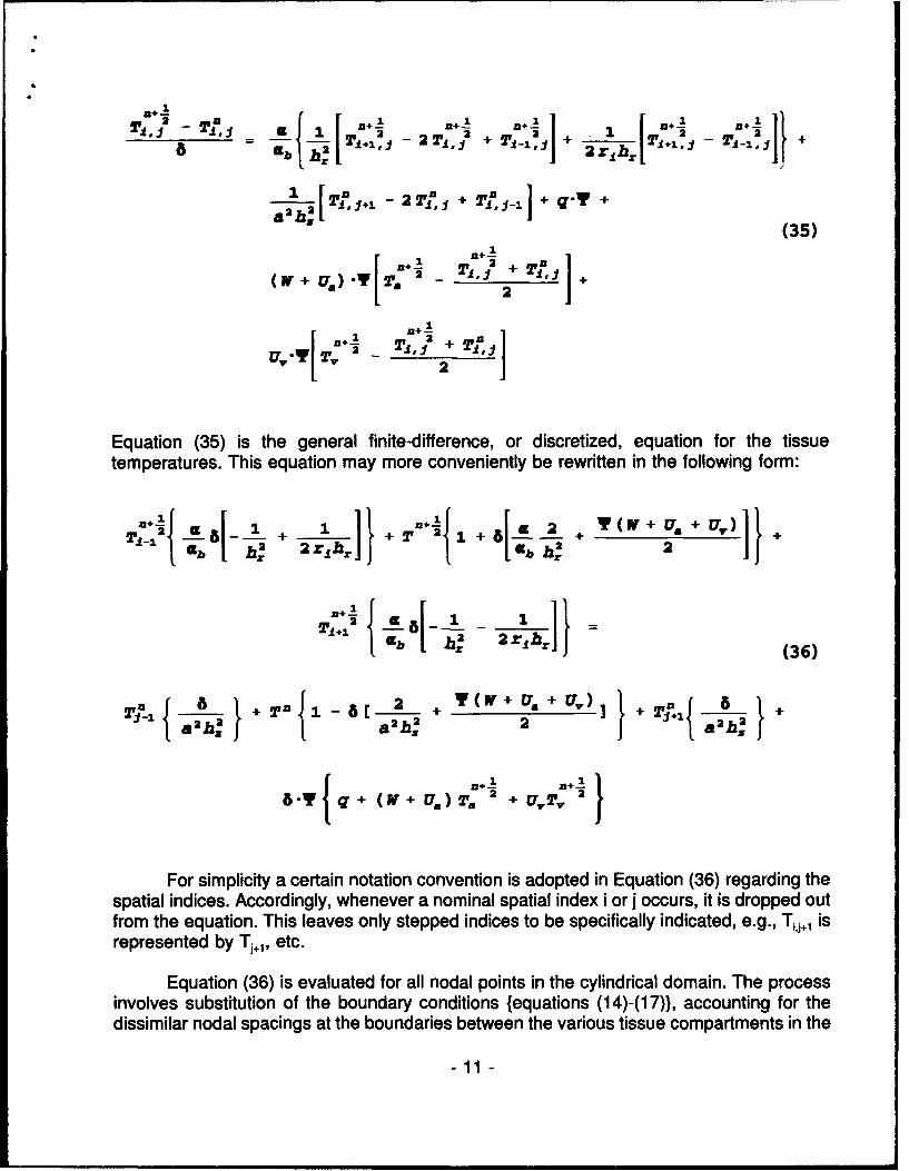
Equation (35) is the general finite-difference, or discretized, equation for the tissuetemperatures. This equation may more conveniently be rewritten in the following form:
1 -11 1 + -!! Y(V+U + )' 2 -8+1--M+ 2 2 + +TI_ 3 b h 2 2 h r [ 24 2
I -b h, 2rh} (36)
a.ha r 2 + Y( if-+Us J Uh +
+ +
B"/' I (+ lw+UaT.a + U'T 7 j
For simplicity a certain notation convention is adopted in Equation (36) regarding thespatial indices. Accordingly, whenever a nominal spatial index i or j occurs, it is dropped outfrom the equation. This leaves only stepped indices to be specifically indicated, e.g., T,,j,1 isrepresented by Tj,1, etc.
Equation (36) is evaluated for all nodal points in the cylindrical domain. The processinvolves substitution of the boundary conditions {equations (14)-(17)), accounting for thedissimilar nodal spacings at the boundaries between the various tissue compartments in the
-11 -

* radial direction, substitution of zero values for perfusion near the external boundaries, etc.Details of the derivation are presented in Appendix A.
This process yields a set of algebraic equations for all the tissue nodal points. Eachequation in this set usually includes three terms for the radial direction and three additionalterms for the axial direction. An additional term not containing unknown tissue temperatures,is also included in each equation. At the boundaries in both directions only two terms arepresent, yielding tri-diagonal matrices for the algebraic set of equations. This property of theset of equations renders it solvable by the Thomas algorithm [11]. To apply this algorithmEquation (36) is now written in matrix notation:
(i - Arl.{T:,2 } X + 6-A ].{TJU} + a{s 2 (37)
where [I] is a unit matrix, A, and Ak are the elements of the tri-diagonal matrices in theradial and axial direction, respectively, and {S÷ 112) is a one dimensional vector containing allremaining terms in Equation (35) which do not multiply the tissue temperatures. Derivationof these quantities for all nodal points is presented in Appendix A and a summary of allcoefficients is given in Tables 1-3.
It is noted that Equation (36) indicates the calculation of the first half time-step only.To complete a full time-step, an equation similar to Equation (36) is required:
[i -a'Az]{Tin'} X [+ 6 A I.T,2 } .S 2 Ii(38)The particular formulation employed in the present analysis assumes that the S-vector
in Equations (37) and (38) is evaluated only once per full time-step, i.e., at the one half time-step. It is then maintained constant for the two calculation passes in both radial and axialdirections. The S-vector contains the temperatures of the large blood vessels at the axialnodal points which provide the thermal coupling between the tissue and the circulatorysystem. To calculate these temperatures, a forward-difference approximation for the timederivatives in Equations (12) and (13) is employed. Two additional assumptions are made,regarding the average arterial and venous blood temperatures and average tissuetemperature appearing in these equations. First the average temperature of the blood in anyone of the two vessels is taken as an arithmetic mean of the two enclosing axial nodal points:
Tb 1 ( Tb, 1, + 7b, oud (39)
-12-

NODE i- ii1
..... . ........
z•~h1 -2- a 1 h" 1,2h h,
cc I l - -1i
I )"h "
00
U,! ) - h,(-) I(cc! Jw+Ua +U,
12 2
lu- -
a2,~ W+ Us+ U., ah,2hnJa. 2 JT2b CCC b 3 .( W + Usi + U) Cb (l+.y)i.h h-)/h-
-'1'111 _ 1,ow
5 b: r 2- "r h, h, +2 r,,
o a*2 Y.W a._2
LU
oI
-i a 1 af 1f 2h- l-i
,b.(,y).hi h, ,J .w Lb (1 +y)-h,(-h)2
c -,1 +'-
..l 0 2 Y-W -2- + 0
LU ab h2 i a,I.- r -h€-'
.• .. 3 . Y W
Table 1: Coefficients in the radial-direction [Ar] matrix.
- 136-

NODE-1 J I 1+
TEMPERATURES ARE SPECIFIED AT THIS NODE; CALCULATION BEGINS AT j =2.
8 2 v. h 1w, 2,.,. u,
__ 12
@C 2 ,hh,2 h.B•
_..
w
a c0
2 3(W +hU,]+U4c :5 a2 hZ2za
cc
2 2
;7 2 -hzz 0~i
lU 2ti
-u
2 2 21+h 1
z ,'0 -h [1+ 0
Table 2: Coefficients in the axial-direction [Ar] matrix.
- 14 -

NODE
V .{qI[W÷U.I.T. 2+U,.T, 2
cc
'izCC 2 +WT"*,,+UT 2 2B'To
-J (W4 U.) 1 2S. . ] C91b hr
cc
z
LUJ 0h
I--l
Table 3: Coefficients of the {S} vector.
- 15 -
Similarly, the average tissue temperature for exchanging heat with any of the large bloodvessels, is taken as the arithmetic mean of the tissue temperatures at the two enclosing axialnodal points:
•= -• •(ui,+•i,-1) (40)
With these assumptions the integrals indicated in Equations (12) and (13) are replaced bynumerical summations to yield:
-M+1-T_ ( j) = 2r [ -B. (J-1) + A.-SMU - Y. - H.,,j:(i) +
(41)
2.-B. (J-1- A.-sm. ] 2,T (J-1 + -. r 7-sU +, T,,--T• (J)
and,
T (j) + 2 -B,, (j1 ) -2 -A,-SUM1. -Y, - Hv -T () +
[-2 -B,(-1)+ A.SMUrn]2'4' 1 + 1 Y, SUAM+ H~. F(i+ (42)
where:
A&=, R )2 (43)
-16-

B&axojv = AsDX arv D x V (44)
yeAxV = A, uAr v 'Rz -2 (45)
hay (46)=ADv kb - X.A&
X-1
SaUW • (ij-1 )-(rf2 • -r2) (47)
NF-i
SUM2 = • { ,(i,j-1) .T¢i,j) }(ri+-4) (48)
and,
NI-1
SUM3 = Vii ){ ii- +2'ij T.r' 1 )(9
According to the present formulation, the symmetry condition at the centerline of thecylinder, Equation (2), is satisfied by excluding the first one-half division in the radialdirection, Fig. A.2. However, in performing the summations indicated in Equations (47)-(49),the contribution of this region is included in order that mass conservation requirements besatisfied.
PHYSICAL AND PHYSIOLOGICAL PARAMETERS
Three interrelated groups of parameters are required for calculating the temperature
field in the model. These are: (a) geometrical parameters, depicting the anatomical details
-17-

of the modeled organ, (b) thermophysical parameters, representing, primarily, the transportproperties of the tissue, and, (c) physiological parameters simulating variables such as bloodflow or metabolic heat generation rate.
Accurate and detailed information on these parameters is not available. Moreover,individual vaiabilities among humans make it almost impossible to formulate a universal setof parameters for the model. Nevertheless, a reasonably accurate set of parameters may beidentified for the purpose of studying the behavior of the model.
Table 4 lists the properties used in the model. Data are given for the fourcompartments, or organs which make up the model, i.e., core, muscle, fat and skin.Additional data are given for blood. Most of the entries in Table 4 were compiled fromReferences [8] and [12]. Blood perfusion and metabolic heat generation rates were estimatedas follows. According to Burton [13], the average blood flow in the finger of a subject "whois comfortable as regards the temperature of the surroundings" is in the range of 15-40cc/min/100 cc tissue. We assumed the lower limit of this range to be representative of thebasal blood flow rate in the unperturbed finger. Converted into SI units, and assuming Table4 value for blood density, this basal value is given by 2.65 kg/M3 sec. This basal rate wasused for calculating the organ-specific values by assuming the geometrical values of Table4 and accounting for the absence of blood flow in the fat layer.
Also listed in Table 4 are the values for "nutritional" blood flow rates in the variousorgans of the finger. These values represent the flow rates in a fully constricted fingerexposed to a cold environment. Values in the literature for this condition are in the range of0.3-1.0 cc/min/1 00 cc tissue [13-15]. For most of this study we assumed a nutritional bloodflow value of 0.5 cc/min/100 cc tissue or, 0.0883 kg/M 3 sec. Values for the different organscf the finger are listed in Table 4.
Yet another set of values relates to the basal metabolic heat generation rate in thevarious organs. These were estimated by assuming that the nutritional blood flow rate ismaintained for the purpose of supporting the metabolic activities of the tissues under allconditions. Thus, average oxygen extraction rates may be assumed for estimating the basalmetabolic heat generation rates. According to Cooney [16], typical oxygen concentrationlevels in the blood are 0.195 and 0.145 liter O/liter blood for tissue inlet and outlet,respectively. The average caloric equivalent of 1 liter of oxygen may be taken at 20.9 kJ (5kcal) to yield the basal metabolic heat generation values listed in Table 4.
In listing these values, one adjustment was made in regard to the metabolic rate ofthe fat layer. Although basal blood flow rate to this organ was assumed to be practically zero,some metabolic activity could still be assumed for this organ. Accordingly, a very low levelof 5 W/m3 was arbitrarily assigned to the fat layer.
-18-

RATIO THERMAL SPECIFIC DENSITY. BASAL BASAL NUTRI-OF CONDUC- HEAT, METABOLIC BLOOD TIONAL
ORGAN TIVITY, RATE, FLOW BLOODTO RATE, FLOW
FINGER RATE,RADIUS,
R/R W/m 0C kJ/kg0C kg/m3 W/m 3 kg/m 3sec kg/m 3sec
CORE 0.7057 1.064 2.102 1401 170.5 5.195 0.173
MUSCLE 0.7954 0.418 3.136 1057 631.9 19.225 0.641
FAT 0.8099 0.204 2.520 900 5.0 0 0
SKIN 1.0000 0.293 3.780 1057 247.4 7.526 0.251
BLOOD 0.450 3.899 1060
Table 4: Property values used in the numerical computations.
-19-

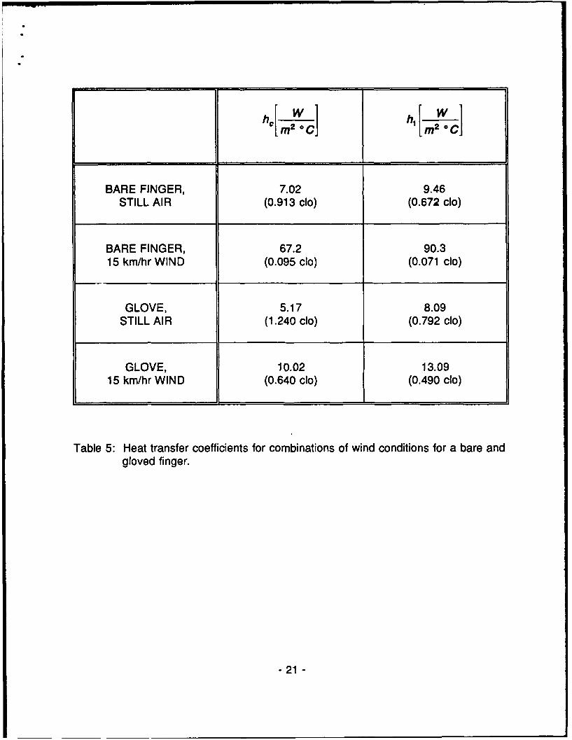
* Heat transfer coefficients used to represent the conditions at the surface of the fingerare listed in Table 5. Four combinations are considered: bare and gloved finger in either stillair (free convection) or windy air (15 km/hr). The values were calculated by standardengineering equations [17] for a 0.08 m long, 0.015 m diameter cylinder. A distinction wasmade between the cylindrical surface of the finger along its axis versus the spherical-like tip.The glove was represented by a 3-layer ensemble depicting a 2.86 mm (0.09 in) wool layer,1 mm of still air gap and a 1.27 mm (0.05 in) leather shell. Also shown in this table are theequivalent clo values of the various entries which conform well to the range of valuesmeasured on a variety of gloves [18,19].
TESTING OF THE NUMERICAL CODE
A rigorous series of benchmark tests was devised and carried out to verify the stabilityand convergence of the numerical code written for the model. Programming was done inTurbo Pascal Version 6.0 for IBM-compatible personal computers. Appendix C contains acomplete listing of the source code and the operating instructions for the program.
In the first group of tests, all physiological parameters, i.e., qm, wb, Ua, uv and ha, wereset to zero. This rendered the problem a simple, two dimensional heat transfer problem. Intests #1-3, the heat transfer coefficients on the surfaces of the cylinder, h, and h. were alsoset to zero thereby creating an adiabatic cylinder except for the base (z=0). In test #1 initialand boundary temperatures at z=0 were set to 300 C and the program was run for 200,000time steps, 0.1 second each. Throughout the test no temperature changes were observedanywhere in the mesh, as is to be expected. In tests #2 and 3, a change was made in theboundary condition at z=0 after the initial 100 time steps. In test #2, run for 100,00 timesteps, 1 second each, the change was from 20' C to 300 C. The inverse change was madein test #3 which was run for a total of 300,000 time steps. In both cases the temperaturesanywhere in the mesh approached the boundary temperatures and remained stable.
In test #4 an active heating source was introduced into the cylinder, i.e., q.>0, whilestill maintaining the other parameters inactive as above. Values used for the heating sourcewere those listed in Table 4 for the basal metabolic heat generation rate. The program wasrun for a total of 2,000,000 time steps, 0.1 second each. Mesh temperatures have stabilizedafter 600,000 time steps.
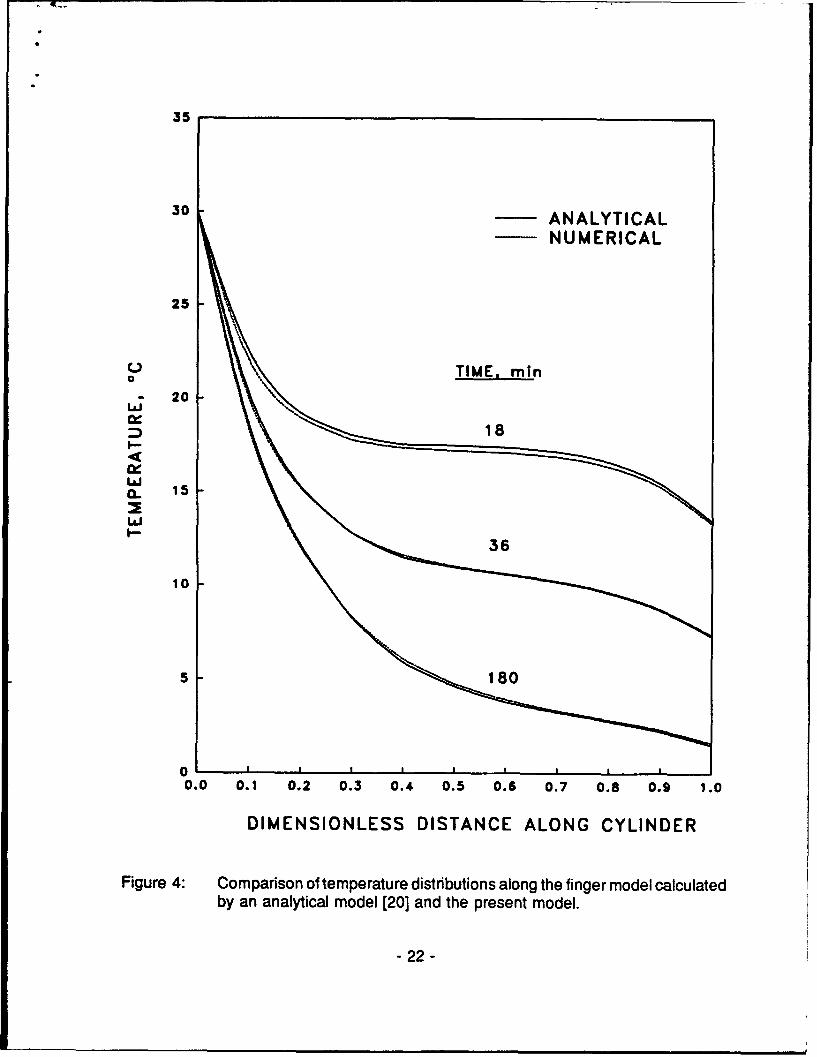
The results of the cylinder model, with an internal heating source, were compared tothose calculated by a one-dimensional analytical solution [20]. The comparison between thesurface (external) temperatures as calculated by this model and those of the analytical modelis shown in Fig. 4. It is noted that precise comparison of these two cases
- 20 -
hc' 2WCW] hi mr °C]
BARE FINGER, 7.02 9.46STILL AIR (0.913 CIo) (0.672 cIo)
BARE FINGER, 67.2 90.315 km/hr WIND (0.095 cIo) (0.071 cIo)
GLOVE, 5.17 8.09STILL AIR (1.240 cIo) (0.792 cIo)
GLOVE, 10.02 13.0915 km/hr WIND (0.640 cIo) (0.490 cIo)
Table 5: Heat transfer coefficients for combinations of wind conditions for a bare andgloved finger.
- 21 -
35
30 ANALYTICAL
NUMERICAL
25
L TIME, min20- 20
LLJ
L&J0, 15
L&JI-36
10 1
0.0 0.1 0.2 0.3 0.4 0.5 0.6 0.7 0.8 0.9 1.0
DIMENSIONLESS DISTANCE ALONG CYLINDER
Figure 4: Comparison of temperature distnbutions along the finger model calculated
by an analytical model [20] and the present model.
- 22 -
"is not possible since no radial temperature variations are included in the analytical model.Nevertheless, the two sets of plotted results seem to agree well, with the numerical resultsslightly under predicting the analytical ones at the shorter times into the run.
In test #5, q, was reset to zero and h, and h,, the heat transfer coefficients with theenvironment, were set to a very high value of 700 W/m 2 0C. Initial mesh temperatures wereset at 300 C and the environmental temperature was maintained at 260 C. After 100 timesteps, the boundary temperature at z=0 was reset to 200 C and the program was run for100,000 time steps, 1 second each. Due to the high value of the heat transfer coefficientsused, a rather flat temperature profile of 260 C was established and maintained throughoutthe mesh except for a short drop to 200 C visualized near the base of the cylinder, as is tobe expected.
In test #6, blood perfusion was activated at the basal values listed in Table 4. Otherparameters were maintained inactive. Initial mesh and arterial temperatures were set at 200C. After the initial 1000 time steps, 0.1 second each, both mesh and arterial temperatureswere reset to 30' C at z=O. The test was run for a total of 200,000 time steps and meshtemperatures converged on 300 C and remained stable for the duration of the test.
A similar test was run with the addition of heat exchange between the major bloodvessels and the mesh points. Results of this test #7 were essentially similar to those of test#6.
In test #8 counter-current heat exchange between the major blood vessels themselveswas also activated. Running conditions were identical to those of test #6 except that a totalof 1,000,000 time steps were utilized. Mesh temperatures have stabilized at 300 C after100,000 time steps.
As was to be expected, the execution of the code was sensitive to the size of the timestep and the number of spatial divisions used in the numerical code. These two topics arediscussed separately. It is firstly noted that the method of alternating directions applied to thesolution of the mesh temperatures yields an unconditionally stable scheme of solution [10].Thus, the source for this sensitivity must reside in Equations (7) and (8) representing the heatbalance in the major blood vessels. These two equations are essentially first order ordinarydifferential equations. Thus, the terms multiplying the independent variables on the righthand-sides may be used to estimate the maximal time step that will ensure stability of theEuler's scheme used to solve them.
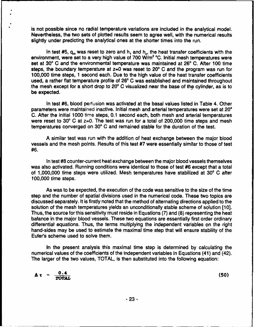
In the present analysis this maximal time step is determined by calculating thenumerical values of the coefficients of the independent variables in Equations (41) and (42).The larger of the two values, TOTAL, is then substituted into the following equation:
A 1; 0.4 (50)-OTAL
- 23 -

to yield the time step which ensures numerical stability. Values obtained by Equation (50) areconservative since a factor of 2 may be used instead of 0.4 [21]. Experience with running ofthe code proved that this requirement on the time step could, indeed, be relaxed somewhatwithout adversely affecting the stability of the code.
The sensitivity of the code to the number of divisions used in the numerical networkbecame apparent when an overall steady state heat balance was calculated for the fingermodel. In all cases studied the number of divisions in the radial direction was kept constantat 12 (Table 6). A relatively simple combination of parameters was used in the computationsin which the finger was assumed to be insulated from the environment, no metabolic heatwas generated and no counter-current heat exchange between the major blood vessels wasallowed. In addition, the thermal conductivities of all tissue compartments were made uniformat the value of the muscle. Under these conditions, the only heat supply to the tissue wasdue to blood perfusion and the only heat removal mechanism was by conduction at the baseof the finger, i.e., at z=0.
Figure 5 shows the ratios calculated for the heat transported by the major bloodvessels to the heat conducted away as a function of the number of axial divisions. It isevident that a heat balance is not satisfied for the smaller number of divisions in the axialdirection. Only when 20 divisions are used, the heat source essentially equals the heat sinkto satisfy a heat balance.
A similar, but more involved, set of benchmark tests was also run. In this set bothmetabolic heat production and heat exchange with the environment at the finger tip wereincluded in addition to blood perfusion and heat conduction at the finger base. A steady-stateenergy balance offset of about 32% was initially obtained for 25 axial and 9 radial divisions.This offset gradually dropped to less than 1% when 75 axial divisions were used. This valuewas deemed quite satisfactory for a steady-state energy balance and served as an additionalverification of the numerical code.
Temperature distributions along the external surface of the model are plotted in Fig.6 also as functions of the number of axial divisions. It is clearly seen that the finaltemperature obtained is a function of the number of divisions in the axial direction. For theparticular case studied here it seems that 20 divisions yield quite an accurate result. This,however, required a much longer running time than for the fewer divisions. Thus, the desiredaccuracy of the results may have to be determined by considerations such as the total CPUtime required for running the program for a given computer.
Based on the series of benchmark tests as outlined here, it may be concluded that thecode written for the model is stable and converges to reasonable results for the entire rangeof parameters considered here.
- 24 -

LENGTH OF CYLINDER, cm 8.0
DIAMETER OF CYLINDER, cm 1.5
DIAMETER OF ARTERY, cm 0.2
DIAMETER OF VEIN, cm 0.3
DISTANCE BETWEEN ARTERY AND VEIN, cm Eq. (B9)
HEAT TRANSFER COEFFICIENT BETWEEN ARTERY Eq. (B6)OR VEIN AND THE TISSUE (Ua or Uj)
COUNTERCURRENT HEAT EXCHANGE COEFFICIENT Eq. (B8)BETWEEN ARTERY AND VEIN (ha or hv)
NUMBER OF DIVISIONS IN THE RADIAL DIRECTION
CORE MUSCLE FAT SKIN TOTAL
3 3 2 4 12
Table 6: Parameters used in the numerical computations.
- 25 -

0
01.0
o..j--
lOu
Zz
I--
5 6 7 8 9 10 11 12 13 14 15 16 17 18 19 20NUMBER OF" DIVISIONS IN AXIAL DIRECTION
30.6
0•.4
0 3 45 6 7 8 9 10 11 12 13 1 ,4 15 16 17 "18 19 20NUMBE OIVISIONS IN AXIAL DIRECTION
Uj
W 30.4
- 20,~30.2
0 1 2 3 4 5 6 7 8 9 10 11 12 13 14 15 15 1718S 19 20NODAL POSITION IN AXIAL DIRECTION
Figure 5 (top): Ratios of steady state heat flow in vs. heat flow out as affected bythe number of divisions in the axial direction.
Figure 6 (bottom): Steady state temperature distributions of the external surface ofthe finger model as affected by the number of divisions in the axialdirection.
- 26 -

RESULTS AND DISCUSSION
A number of cases are considered to demonstrate the range of capabilities of thismodel. Additional parameters used in these demonstrations are listed in Table 6.
Figures 7-10 show the steady state temperature distributions in the finger model forcombinations of insulation (bare vs. gloved finger), wind velocities and finger blood flow. Inall these cases the environmental temperature was maintained at 00 C. and finger basetemperature as well as incoming arterial blood temperature were kept constant at 300 C.
All four figures demonstrate the major role played by blood flow in the thermaleconomy of the finger. It is clearly noted that rather comfortable temperatures are maintainedin the finger for as long as blood flow remains high (at basal level in this case). Theexception is the case of the bare finger in a windy environment of 15 km/hr in which theenhanced heat loss offsets much of the beneficial effect of high blood flow to the finger.
In all cases studied, temperature of the distal segments of the finger dropped to verylow levels and almost equilibrated with the environment. This is the case even when a two-layer glove is donned on the hand as is also suggested in another study [22]. The onlydifference among the cases studied here is in the time course of change in thesetemperatures. This difference is shown in Fig. 11 in which finger tip skin temperatures areplotted vs. time for all 4 cases. Low blood flow, at the nutritional level, which is to beexpected for this low environmental temperature, was assumed for all cases.
As seen in Fig. 11, the bare finger in windy air will be the quickest to drop intemperature. It would practically equilibrate with the environment after about 10 minutes. Thegloved finger, under the same windy environment, would be much better protected and wouldrequire about 60 minutes before it equilibrates with the environment. Interestingly, a barefinger in still air seems to be better protected than a gloved finger in windy air.
These results may also be presented in terms of endurance times, defined as the timefor any temperature on the finger to reach 50 C. Accordingly, the endurance times for thebare and gloved fingers in windy air would be about 2.5 and 22 min, respectively. Thesetimes would be longer, at 32 and 43 minutes, respectively, when the bare and gloved fingersare exposed to still air.
- 27 -

35: a- , , , ,
30
HIGH BLOOD FLOW V-
25
20 BARE FINGER; 00 C; STILL AIR
a:*-- ARTERIALv--- VENOUS
w*-. SKINa. 15
10
0 p '--"-- "---
0.0 0.1 0.2 0.3 0.4 0.5 0.6 0.7 0.8 0.9 1.0
DIMENSIONLESS DISTANCE ALONG THE CYLINDER
Figure 7: Steady state temperature distributions of a bare finger in still air for basaland nutritional blood flows.
- 28-

30 ~ 4~ -
HIGH BLOOD FLOW
25
SU
20 ! GLOVE; O° C; STILL AIRl ARTERIAL
v.-v VENOUS
w t SKINB- 15
I-
5 LOW BLOOD FLOW5
0 90.0 0.1 0.2 0.3 0.4 0.5 0.6 0.7 0.8 0.9 1.0
DIMENSIONLESS DISTANCE ALONG THE CYLINDER
Figure 8: Steady state temperature distributions of a gloved finger in still air forbasal and nutritional blood flows.
- 29 -

35
SBARE FINGER; 0 C; 15 km/h
30 S•- ARTERIAL
•-4 VENOUS
25~- SKIN
HIGH BLOOD FLOW
oS
0
a 20
10 300--
0. . . . : - . -7 08 09 j.
-300

35
30 HIGH BLOOD FLOW S
25
U; 20
GLOVE;. 00 C; 1Skm/h
Ix-0 ARTERIAL. 15v-v VENOUS
15 *-. SKINL--
1 0 .
0
0.0 0.1 0.2 0.3 0.4 0.5 0.6 0.7 0.8 0.9 1.0
DIMENSIONLESS DISTANCE ALONG THE CYLINDER
Figure 10: Steady state temperature distributions of a gloved finger in windy air forbasal and nutritional blood flows.
- 31 -

33 15
30 To =0 *C
WR 0 GLOVE1 0 LOVESTILL AIR
2 . •=,A BARE HAND
NA GLVE5 km/hr WINDBAD\% 0 A BARE HANDm
0 ID
S20 N A3 LOW BLOOD FLOW
0
C LZ A2 157
100 3 0 O6
I-- 32 -
A
A
A
A
10 20 30 40 50 60
TIME, min
Figure 11: Temperature variations on the dorsal tip of the bare and gloved fingermodel with nutritional blood flow for still and windy air.
- 32 -

The effect of counter-current heat exchange between the major blood vessels isdemonstrated in Fig. 12. Numerical values of the parameters used for this figure are listedin Table 6. The two groups of curves in Fig. 12 show the steady state arterial and venoustemperature distributions along the finger with and without counter-current heat exchangebetween these vessels. As soon as this mechanism is activated, the arterial temperatureseems to drop considerably due to the exchange of heat with the cooler vein.
The main purpose of counter-current heat exchange is to conserve body heat in a coldenvironment. This is effected by firstly depriving the extremity of the rich supply of blood, asis assumed here by dropping blood flow from basal to nutritional level. An additional effectis achieved by lowering the temperature of the extremity through the thermal coupling whichexists between the major blood vessels and the tissues. The arterial temperature along theextremity is made to loose heat by counter-current heat exchange to the cooler vein. This,in turn, causes tissue temperatures to decrease as the artery constitutes the main heatsource for the extremity. In the case shown in Fig. 12, about 0.093 W is lost to theenvironment from the finger which decreases to 0.08 W for a reduction of about 14% infinger heat loss when counter-current heat exchange is activated.
Another case of cold induced vasodilatation (CIVD) in the finger is shown in Fig 13.CIVD is known to occur in a percentage of the population and is manifested by ratherperiodic increases in finger skin surface temperatures, e.g., [23,24]. Although the precisemechanism for this phenomenon is not thoroughly understood, there is ample evidence toindicate that intermittent increases in the otherwise constricted blood flow to the finger causethese temperature changes.
In calculating the data for Fig. 13, it was assumed that the periodic blood flow changesmay best be approximated by triangular-shaped surges. These surges were assumed tooccur only in and adjacent to the tip of the finger while blood supply to the other segmentsof the finger remained unchanged. The initial temperature of the entire bare finger, exposedto still air at 0* C, was set at 300 C. At the beginning of the exposure, blood flow in the fingerwas assumed to drop to the nutritional level (Table 4). This situation was assumed to persistfor 20 min. Next, a 3 minute linear increase to 10 times the initial value in blood flow to thetip of the finger was allowed followed by a symmetrical decrease back to the nutritional level.Nutritional blood flow was next maintained for 15 minutes and was followed again by anidentical triangular-shaped change in blood flow to the tip of the finger. During the final 15minutes of the run, blood flow was reset to the nutritional level.
Skin temperature variations are shown in Fig. 13 for three locations along the finger.The curves are plotted for the base, the middle point along the finger and for the tip of thefinger. The solid line represents finger tip temperature variations for constant nutritional bloodflow without the periodic bouts of CIVD. It thus provides a worst case scenario forcomparison purposes. It is clearly seen that increases in blood flow causeincreases in fingertemperatures, as is to be expected. These changes are more pronounced at the tip of thefinger than at the more proximal locations primarily because blood flow changes due to CIVDare assumed to take place in this area only.
- 33 -
55
ARL . Y ... 1 N
30 o U NO COUNTERCURRENT HEAT EXCHANGE
A COUNTERCURRENT 14EAT EXCHANGE
25>
20
La a
I--
10
A\ 0
a-a \*• \\:
_0
0 0.1 0.2 0.5 0.4 0.5 0.S 0.7 0.6 0.1 1.0
DIMENSIONLESS DISTANCE ALONG THE CYLINDER
Figure 12: Effect of counter-current heat exchange on arterial and venoustemperature distributions.
- 34 -

30
28 BARE FINGER
26 STILL AIR
24 OC ENVIRONMENT24 ° •o
22 ooomoccK300ocmccommIBASE OF FINGER
20
18
16
14 A&",, MIDDLE OF FINGERit, An
0.. 2 A2AA
10 S10E0*0 FINGER * %1 ,.
TIP TEMPERATURE ,6 FOR CONSTANT
/
NUTRITIONAL FLOW
4 aLA.
2 BLOODPERFUSION 2 o0
0 00 5 10 15 20 25 30 35 40 45 50 55 60
TIME, min
Figure 13: Dorsal temperature variations at the tip and middle of the finger model forcold induced vasodilatation.
- 35 -

Another interesting result relates to the course of change in finger tip temperature forthe case shown here. It seems that CIVD, which may be characterized as a heating source,causes the tissue temperatures to increase noticeably for as long as it is active. Once thismechanism gets shut off, tissue temperatures resume the exponential-like decay to levelsclose to those attained without CIVD. This decay is enhanced by the larger temperaturedifference between the tissue and the environment that has been established as a result ofCIVD. As a matter of fact the temperature difference at the finger tip after one hour betweenthe case involving CIVD and the one without it would be a mere 0.80 C, for the casepresented here.
It is recognized that the details shown in Figs. 7-13 are dependent on the parametersand assumptions used in the computations. However, certain trends are clearly indicatedwhich will likely vary in detail and magnitude as the values of these parameters are altered.
- 36 -
REFERENCES
1. Knockel, J.P., Environmental heat illness. An eclectic review, Arch. Intern. Med.,133:841-864, 1974.
2. McCarroll, J.E., Denniston, J.C., Piere, D.R. and Farese, L.J., Behavioral evaluation ofa winter warfare training exercise, US Army Research Institute of EnvironmentalMedicine, Report No. T 1/78, 1977.
3. Pennes, H.H., Analysis of tissue and arterial blood temperature in the resting forearm,J. Appl. Physiol., 1:93-122, 1948.
4. Mitchell, J.W., Galvez, T.L., Hengle, J., Myers, G.E. and Siebecker, K.L., Thermalresponse of human legs during cooling, J. Appl. Physiol., 29:859-865, 1970.
5. Eberhart, R.C., Heat transfer for models in specific organs, in: Heat Transfer inMedicine and Biolo-gy: Analysis and Applications, A. Shitzer and R.C. Eberhart (eds.),Plenum Press, N.Y., 1:273-321, 1985.
6. Wissler, E.H., An analysis of factors affecting temperature levels in the nude human, in:Temperature: its Measurement and Control in Science and Industry, J.D. Hardy (ed.),Reinhold, N.Y., Part 3, 603-612, 1963.
7. Stolwijk, J.A.J. and Hardy, J.D., Temperature regulation in man - a theoretical study,Pflugers Arch., 291:129-162, 1966.
8. Arkin, H. and Shitzer, A., Model of thermoregulation in the human body, Reports No.EEC-148 (Part I - the heat transfer model), EEC-149 (Part I - the control model) andEEC-150 (Part III - model behavior and comparison to experimental results ofexercising, heat stressed subjects), Energy Engineering Center, Faculty of MechanicalEngineering, Technion, Israel Institute of Technology, Haifa, Israel, 1984.
9. Tikuisis, P., Gonzalez, R.R. and Pandolf, K.B., Thermoregulatory model for immersionof humans in cold water, J. Appl. Physiol., 64(2):719-727, 1988.
10. Ames, W.F., Numerical Methods for Partial Differential Equations, Thomas Nelson andSons, New York, 1977.
11. Young, D.M., Iterative Solution of Large Linear Systems, Academic Press, New York,1971.
- 37 -
12. Stolwijk, J.A.J. and Hardy, J.D., Control of body temperature, in: Handbook ofPhysiology, Ch. 4, 59-60, 1977.
13. Burton, A.C., The range and variability of the blood flow in the human fingers and thevasomotor regulation of body temperature, Am. J. Physiol., 127:437-453, 1939.
14. Freeman, N.E., The effect of temperature on the rate of blood flow in the normal and
in the sympathectomized hand, Am. J. Physiol., 113:384-398, 1934.
15. Lotens, W.A., A simple model for foot temperature simulation, TNO-Report IZF, 1989.
16. Cooney, D. 0., Biomedical Engineering Principles - An Introduction to Fluid, Heat andMass Transport Phenomena, Marcel Dekker, Inc., New York, 1976.
17. Ozisik, M.N., Heat Transfer - A Basic Approach, McGraw Hill Book Co., N.Y., 1985.
18. United States Army Research Institute of Environmental Medicine, Table of bestavailable data on gloves, unpublished.
19. Santee, W.R., personal communication, 1992.
20. Shitzer, A., Stroschein, L.A., Santee, W.R., Gonzalez, R.R. and Pandolf, K.B.,Quantification of conservative endurance times in thermally insulated cold stresseddigits, J. Appl. Physiol., 71(6):2528-2535, 1991.
21. Myers, G. E., Analytical Methods in Conduction Heat Transfer, McGraw Hill, New York,1971.
22. Goldman, R.F., The Arctic soldier: Possible research solutions for his protection, In:Science in Alaska, Proc. of the 15th Alaskan Science Conference, College, Alaska, G.Dahlgren ed., Alaska Division, Assn. for the Advancement of Science, pp. 401-419,1964.
23. Lewis, T., Observations upon the reactions of the vessels of the human skin to cold,Heart, 15:177-208, 1930.
24. Livingstone, S.D., Changes in cold-induced vasodilatation during Arctic exercises, J.Appl.Physiol., 40(3):455-457, 1976.
- 38 -

25. Elkowitz, A.B., Shitzer, A. and Eberhart, R.C., Transient temperatures in tissues withnon-uniform blood flow distributions, ASME Transactions, Journal of BiomechanicalEngineering, 104(3), 202-208, 1982.
26. Mitchell, J.W. and Myers, G.E., An analytical model of the countercurrent heat exchangephenomena, Biophysical J., 8:897-911, 1968.
27. Keller, K.H. and Seiler, L., An analysis of peripheral heat transfer in man, J. Appl.Physiol., 30(5):227-234, 1971.
28. Holman, J.P., Heat Transfer, McGraw Hill Book Co., New York, 2nded., 1968.
- 39 -
GLOSSARY
VARIABLES
a - dimensionless ratio of cylinder length to radius multiplied by the ratio of blood to
tissue thermal diffusivities, Eq. (23).
Aa or v) - dimensionless ratio of cylinder to blood vessel radii, Eq. (43).
[A,] - coefficient matrix in radial direction, Eqs. (37) and (38).
[AJ - coefficient matrix in axial direction, Eqs. (37) and (38).
B1(a or v) - dimensionless ratio of blood flow rate to blood mass contained in a vesselelement per unit of normalized time, Eq. (44).
Bi - Biot modulus indicating the dimensionless ratio between heat convected by theenvironment to heat conducted in the cylinder, Eqs. (28) and (29).
c - specific heat, J-kgl.°C'.
h - heat transfer coefficient between the cylinder and the environment at thecircumferential surface, Wem-2.°Cl
h, - heat transfer coefficient between the cylinder and the environment at the cylindertip, W em 2 .0Cl
h(r or z) - dimensionless distance between two adjacent nodes in the radial or axial direction,respectively.
hav - heat transfer coefficient between concomitant artery - vein pairs, W°C1
H(av or va) - dimensionless heat transfer coefficient between concomitant artery - vein pairs, Eq.(46).
k - thermal conductivity, WemI'-.C'
L - cylinder length, m.
m(a or v) - mass flow rate of arterial or venous blood, kg.s 1 .
M - total number of nodal points in axial direction.
M(a or v) - mass of arterial or venous blood contained in a vessel element, kg.
- 40 -

N - total number of nodal points in radial direction.
qM - volumetric metabolic heat generation rate, W-m 3
q - dimensionless volumetric heat generation rate, Eq. (25).
r - radial coordinate, m.
r - dimensionless radial coordinate, Eq. (19).
R - cylinder radius, m.
{S) - vector of terms in matrix equations, Eqs. (37) and (38).
S 2 - numerical summations, Eqs. (47) - (49), respectively.SUM3
t" - time, s.
T" - temperature, 0C.
T; - temperature at base node, 00.
T* - initial temperature distribution in the cylinder, 0C.
Temp - reference temperature, 00.
T - dimensionless temperature, Eq. (22).
U(a or v) - heat transfer coefficient between an artery or a vein, respectively, and thesurrounding tissue, W.m 3.°C 1 .
U(a ov) - modified dimensionless heat transfer coefficient between an artery or a vein,respectively, and the surrounding tissue, Eq. (45).
Wb - volumetric blood perfusion rate, kgom s"
W - dimensionless volumetric blood perfusion rate, Eq. (26).
Y(or v) - dimensionless heat transfer coefficient between an artery or a vein and thesurrounding tissue, Eq. (27).
z" - axial coordinate, m.
z - dimensionless axial coordinate, Eq. (20).
- 41 -
GREEK LETTERS
ot - thermal diffusivity, m2.s 1.
y - ratio of radial nodal divisions immediately preceding to immediately following a tissuecompartment interface, Eq. (A.10).
8 - dimensionless half a time step, Eq. (34).
p - density, kg.m"3 .
,r - dimensionless time, Eq. (21).
' - dimensionless ratio of blood to tissue thermal inertias, Eq. (24).
SUPERSCRIPTS
-dimensional quantity.
- average value.
SUBSCRIPTS
a - arterial.
b - blood.
i - integer (radial direction).
i - initial.
j - integer (axial direction).
n - integer (time).
r - radial.
t - tissue.
- 42 -

v - venous.
z - axial.
0 - environmental.
- 43 -
"* APPENDIX A - Derivation of the equations for the various matrix nodal points
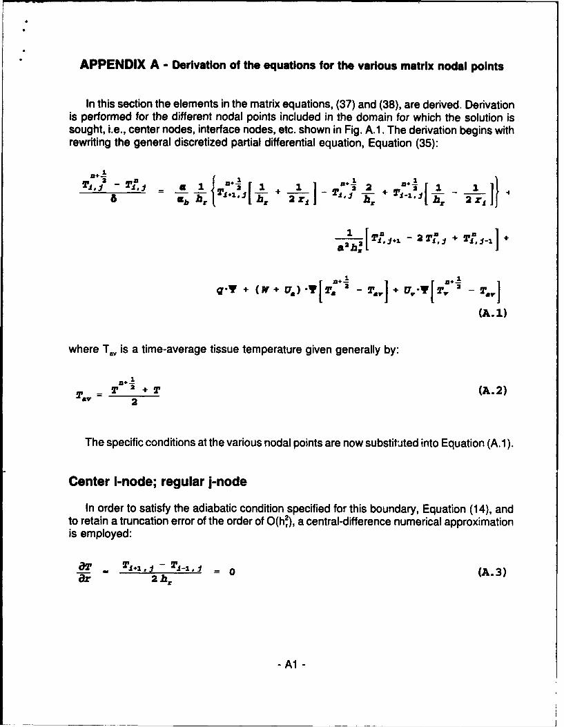
In this section the elements in the matrix equations, (37) and (38), are derived. Derivationis performed for the different nodal points included in the domain for which the solution issought, i.e., center nodes, interface nodes, etc. shown in Fig. A.I. The derivation begins withrewriting the general discretized partial differential equation, Equation (35):
n+1
bhl'"L +211 1 . Tij 2 'm- I 21 1}
2 [ + 1. 1
2- [ 211 - 22' =f + TinJ.-.I +
S}1
q'T + (W + U,) -TL, - Tl+ T -
(A.1)
where Tay is a time-average tissue temperature given generally by:
n+-1
,, T +T (A.2)2
The specific conditions at the various nodal points are now substituted into Equation (A. 1).
Center i-node; regular j-node
In order to satisfy the adiabatic condition specified for this boundary, Equation (14), andto retain a truncation error of the order of O(h2), a central-difference numerical approximationis employed:
T T,,.,$1 - T 1 -1 0 (A. 3)ar 2 h,
- Al-

< Z
o EXTERNAL _(2) (5)
SKIN ....FAT
MUSCLE - - REGVLAR (3)
INTERFACE (3) (7)
CORE
CENTER T) (6)
CYLINDER CENT9ERLINE
J
(1) center i; regular j (4) regular i; end j(2) external i; regular j (5) external i; end j(3) regular and interface i; regular j (6) center i; end j
(7) interface i; end j
Figure Al: Identification of nodal points in the numerical grid
-A2-

with geometrical details shown in Fig. A.2. It follows from Equation (A.3):
Si., = Ti-I • z1 = ZO = 0 (A.4)
which yields upon substitution into Equation (A.1):
As+I: O a+ -i + Yvu U) n+2 (.
+~ h 2 01__
_. { + T - 2 6 -Y lw + u V•) + T++ {a+} (A .5a ••= hS== h= a h-
+6 - q+ (W+U, )T , +2 Ur T,,
External i-node; regular j-node
The boundary condition to be satisfied at these nodes is Equation (15). The numericalapproximation to this equation, depicted in Fig. A.3, which retains the desired truncationerror, is:
a__ r T1 - T'_1 = Bi (T0 - T1 ) (A.6)ar 2 hr
which yields:
r1+3 = +T-_ + 2 "h,'Bi ( TO - Tr) (A.7)
Next, a correction is applied to the equivalent tissue temperature at the external node toaccount for the difference in the heat exchange with capillary perfusion [25]:
T t - 3. + 3 (A.8)
-A3 -

(2)
(1) 1r
(0) Th
ihr
radial divisions
Figure A2: Schematic diagram of the center node
-A4-

i+1
i (=N)h~ri-1
r=]
Figure A3: Schematic diagram of the external-regular node
-A5-

* Substitution of Equations (A.7) and (A.8) into Equation (A.1) obtains:
n,_*"1 26 ah 6" " T -,(w-+ .Ua ,} +
8 9 _ 8(.+_+
{_+ .28 +T 3) B+ 3"-6'-Y - (,+ U.+ v +U,)4b h4 2 b 8z(
-_ + 281 3-8 - (V*U+U1
(i a c ' + 2 ) T0 ElL~b
(A. 9)
Interface i-node; regular j-node(including a regular i-node; regular j-node by setting y=1)
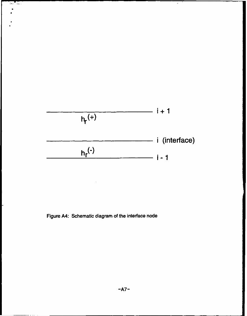
Interface nodes define the boundaries between the various compartments, or organs, ofthe limb model, e.g., core-muscle interface, etc. Numerically the subdivisions in each of thecompartments may be different depending on the extent of any specific compartment and thedesired numerical details. Additionally, tissue properties generally vary among compartmentswhich further justifies the definition of these interfaces. Figure A.4 depicts the interface regionbetween two adjacent tissue compartments in the radial direction. The ratio of the sub-division immediately preceding the interface to that following it, is defined by:
t' h- (A. 10)
for simplicity, the superscripts in Equation (A.10) are omitted with the convention:
h-= h r -r (A. 11)
-A6-
i+1hr(+W
i (interface)hr(')
i-1
Figure A4: Schematic diagram of the interface node
-A7-

* The following numerical approximations are used in order to retain a truncation error of orderO(hP) [10]:
a,2 2 y _z T,_. - 2,T y -¢ T+.2y2 }. +o0 (h2 (A. 12).Z. h• . T.1 +1 + T
aT 2 1{ - 2 T+2(1 T)T+ yT2. + }O(h2) (A.13)
After Equations (A.10) - (A.13) are substituted into Equation (A.1), the following expressionis obtained:
a+ 1.~+ 8YVU
__ = (A. 14)1= h. (_1 _1- + +)h, r
M+ " 21
+8 2. • =6 6 -Y,(,. +.U + )O
n + _1 2
Ti{ h +"T q{ + (- 2 + ,) . 2 + +,71
End j-node; regular i-node
In the present analysis it is assumed that the major blood vessels terminate (artery) andoriginate (vein) in the j-node immediately preceding the end j-node, as depicted in Fig. A.5.Thus, heat exchange with the circulatory system is performed at this node with the capillarybed only. The boundary condition at this node is Equation (17) which is approximated by:
NT TJ - ._ Bi I (To - T.) (A. 15)a-z 2h, i -
-A8-

j-i j(=M)ARTERY
VEIIN
CAPILLARYPERFUSION
Figure A5: Schematic diagram of the end j - regular i node
-A9-

which is rewritten as:
Tj*1 = !j_- + 2h,&B1 ( To - 2,s) (A.16)
yielding, following substitution into Equation (A.1):
ub h, ,[ •.r,
(A.17)
f 28 ~ +TJ. 28 1+ h~ih - Yl l T +il~2hf a2 h 2
2p{}+ 8 lr + VT: 2 } 2 8 j 21 0&2 hS
A10-

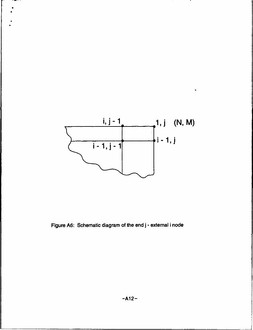
End i-node; external I-node
At this node, which is depicted in Fig. A.6, Equations (15), (17) {or their approximationsEquations (A.7) and (A.16)) and the modification given by Equation (A.8) are to be satisfied.Additionally the major blood vessels origination-termination assumption is also applied toyield:
T1{i b2 11+8 -T-W
Ub KZ 2 8
"-t{ . + 28 B -s26 + +-T-w 141ab h,2 Lb hrB. 3 8 xV
(A.18)
2'{28 +7-1 26[1 + hX81 3''Y=f + TIOI o2., 32 hJ2 10 +Ji~
8.Y.{q+V7T-1 +1 a1 }+ BI:1iTO _.!!_ a B.[ 12& h&X
End j-node; center i-node
At this node both Equations (A.4) and (A.16) apply to yield:
n+11 B+1
. 26 -Y-W r_ £ 2 =
2 o ÷ 1 + -+ 7 -+ _L6"Ii bh 2 gg j
h,22h2 2 TO
n +! 2 Bi11 T 06"Tq+Ta +6 18 2 h
-All -
S
j j (N, M)
i,
1,j
Figure A6: Schematic diagram of the end j - external i node
-A12-

End J-node; Interface I-node
At this node Equations (A.12), (A.13) and (A.16) are substituted to yield:
L, _(-y- -.- J + 1 + +1 b hr
h, h h,,-1 6" hr 3- + a Yh,
-h A12
-A13 -

APPENDIX B - Heat transfer coefficients for the major blood vessels
Under the assumptions of the present study the two major blood vessels, an artery anda vein, traverse each body element in the axial direction, Fig. 1. These vessels exchangeheat with the surrounding tissue. Additionally under certain circumstances there may also bedirect heat exchange between the two vessels. Mitchell and Myers [26] assumed that eachone of these major vessels resides alone in the tissue. An improved assumption is due toKeller and Seiler [27] and Arkin and Shitzer [8] according to which an "influence volume" isdefined by enclosing each vessel by a larger concentric cylinder, Fig. B.1. The conductionshape factor for this situation is given by [28]
2 -x -AZ.
1n( Re) (B. 1)
where Rc is the radius of the enclosing cylinder. As a first approximation this radius may beset as the half distance between the centers of the major blood vessels, D. Thus,
S-1 D (B.2)2
The amount of heat exchanged between any of these vessels and the surrounding tissueis now given by
1nl Zap) (B. 3)
where k is a volume weighted average value for tissue thermal conductivity given by
A-_ fkdV (B.4)
and
- B1-

"INFLUENCE"VOLUME
raor rv
Figure BI: Schematic representation of an "influence" volume enclosinga major blood vessel
-B2-

= - (B.5)
The integral in Equation (B.4) is performed numerically by the trapezoidal rule. The overalltemperature difference in Equation (B.5) includes an average value, T, representing thetissue surrounding the blood vessel. This average tissue temperature is calculated byperforming the integrations indicated in Equations (7) and (8). For these integrals avolumme-ric average heat transfer coefficient, u. o, v is required. This is obtained by"distributing" the overall heat transfer coefficient over the volume of the entire body elementto obtain
2:kAL~ F. 2 . (B)61r/:zv - 4'r zR 2L -_
The direct heat exchange between the artery and the vein may be approximated byassuming a conduction shape factor for two parallel cylinders exchanging heat, the centersof which are spaced by D [28], Fig. B2:
Si.2 -x -AZ
Do ( D2 -r , Z 2) (B.7)
The overall heat transfer coefficient between these cylinders is given by
hav = 2 -x -k-At.o- 2zk L - 2 r• 2 (B. 8)
The distance between the centers of the two major blood vessels is usually known, or canbe inferred, for any body element. For the purposes of the present computations we assumethis distance to be given by four times the geometric average of the radii of these vessels[8]
= (r',-r',) 2 (B.9)
- B3 -

ARTERY VEIN
D
Figure B2: Schematic diagram of an artery-vein pair
-B4-

which yields upon substitution into Equation (B.8)
h 2 2-W k'A
V Cosh-1 (7 (
-B5 -

* APPENDIX C - Program source code listing and operating instructions
Program Environment
1. Hardware requirements : 386 or 486 PC with a 80X87 math coprocessor.
2. TURBO PASCAL 6.0 installed and operating.
3. BGI directory loaded in the TP directory enabling the graphics interface to operate.
4. Option Switches -
A. COMPILE menu bar - DESTINATION set to disk.B. OPTION menu bar - COMPILER set to the 8087 processing mode.
MEMORY SIZE - STACK SIZE set to 65520.
The program consists of four files:
1. FINGER93.PAS is the main body of the program.
2. VARSP.PAS is a Turbo Pascal UNIT containing all global declarations.
3. TISUESP.PAS is a Turbo Pascal UNIT containing the procedures necessary togenerate the coefficients for the tissue equations.
4. PHYSFIN.PAS is a Turbo Pascal UNIT containing all procedures dealing withanatomical data.
The system of Pascal programs utilizing a main program which accesses three UNITSwas necessary since files in TURBO PASCAL 6.0 cannot exceed 65K bytes.
-C1 -

N.B. - all units must be re-ccrpiled to disk each timechanges are made to the code under consideration.Turbo Pascal requires that a *.TPU file exist ondisk for each UNIT in the program. Consequently,the units must be recaopiled each time the usermakes changes to these files. Compiling these fileswith the destination switch set to menmry will notcreate the necessary *.TPU files for the program toexecute successfully. THE UNITS MUST BE -CMPILED
Description of program Units
UNIT FINGER93.PAS { main program)
1. Procedure Initialize;Generates formula calculations for all values required by the program. Data forthis procedure is acquired from the CONST section of UNIT VARSP.
2. Procedure DataDump;Generates file output of initial and calculated data that wail be used by theprogram.
UNIT VARSP.PAS
This unit contains all CONSTant declarations, data TYPEs and VARiable declarationsused by the program. For testing purposes, the initial values assigned in the CONSTantsection may be altered. This area has been identified by the internal documentation. Nochanges should be made in the TYPE sections or the VAR sections since these will have asubstantial impact on program execution. VARSP must be saved and recompiled to diskeach time the test values are changed. This unit contains six sub-modules which functionas utilities of calculation procedures for the generation of coefficients required by the tissueequations.
- C2 -
1. FUNCTION GAMMACalculates the gamma values as required.
2. PROCEDURE PAUSE-CRTA utility that allows the user to halt the programs execution as required.
3. PROCEDURE DERIVECENTERTEMPDerives the temperature at I = 0.
4. PROCEDURE DUMPHALFARRAYSOutputs the all values of the temperature arrays at the half time step.
5. PROCEDURE DUMP_T_ARRAYSOutputs the all values of the temperature arrays.
6. PROCEDURE CALCTATVHALFCalculates the values for arterial and venous temperatures. Variables TABAR,TVBAR, TANODE, and TVNODE are calculated here in preparation for thecalculation of the SVECTOR values.
UNIT TISUESP.PAS
1. Procedure Axial_Dir;Imports the I and J coordinates, identifies the type of node using enumerateddata types and calculates three coefficients for the given I,J location. These arestored in the ORIGAZCOEF array which is used for tissue traversal in theRadial Direction to generate the constant term prior to accessing the code forThomas' Algorithm.
2. Procedure Rad DIr;Generates coefficients utilizing the same approach described above. Thecoefficients are stored in array ORIGARCOEF and are used in the axialtraversal of the tissue matrix to generate the constant term prior to accessingthe code for Thomas' Algorithm.
3. Procedure Establishcoefarrays;Driver block containing nested loops which call procedures 1 and 2 listedabove, thereby loading the coefficient arrays.
- C3 -

• 4. Procedure Traverse;Contains the following nested procedures:
a. Procedure Thomas;Contains code for Thomas Algorithm.
b. Procedure FirstTraverseRadial;Moves appropriate coefficients from arrays generated earlier into variablesneeded by Procedure Thomas. This procedure then calls the Thomasalgorithm procedure and places the new temperatures into the tissuetemperature matrix. A single dimension array is used as an intermediarydata structure in order to hold the 1,J coordinates and correspondingtemperatures.
c. Procedure SecondTraverseAxial;Organized in the same manner as the FirstTraverse procedure. Thisprocedure traverses the temperature matrix in the Axial direction.
d. Main Block of Procedure Traverse;Driver block for establishing the temperature matrix and nested loopingstructure for the number of time steps and print intervals.
UNIT PHYSSP.PAS
This unit contains the following five procedures:
1. PROCEDURE Anatomicalinput;
2. PROCEDURE NumDivisions;These procedures load variables with the necessary anatomical data.
3. PROCEDURE WidthCalculation;Determines the width of each organ, H- values and gamma values.
4. PROCEDURE Estinterfaces;Establishes the location of the organ interfaces and stores them in a datastructure of type SET.
5. PROCEDURE CreateArrays;Establishes a set of values for each organ and a series of arrays containing Riand Hr- values indexed to each I location.
- C4 -
OUTPUT FILES
The following two external output files are automatically created when the program isexecuted.
1. DVALUES.DATFile contains a listing of all significant values used during the current programrun. Some of these are echo prints of values entered in the CONST section ofVARSP.PAS, while others are the result of formula calculations.
2. RTEMPS.DATThis file contains a printout of the time step, arterial, venous, and tissuetemperatures generated of at each time step, at user determined intervalsduring program execution.
OVERVIEW OF PROGRAM OPERATION
1. Prior to running the program, be certain that the following programming conditionshave been established :
A. Turbo Pascal has been properly installed with all the BGI files in the BGI
directory within the TP directory.
B. COMPILE menu bar DESTINATION has been set to DISK.
C. OPTIONS menu bar has been u- o set the compiler to the 8087 numericprocessor.
2. Changing program parameters:
A. Accessible Parameters are found in the VARSP.PAS program unit. Thesehave been separated from the rest of the code by the following sets ofcomments:
- C5 -

(************.******* BEI C•1~ ]POfl•I SEC'I *****************)
(******************* CO NTROL PO"I S "lC* *******************)(*********** N SE•lD B1 ALTI, M B TBS pOn **********)
B. The parameters within the CONTROL POINT SECTION include:
GCDELTASEC ( delta value in seconds)
GCLENGTH and GCDIAMETER { in centimeters)
Radial Divisions
Axial Divisions
TA, TV, TISSUETEMP, ENVIRONMENTALTEMP, andNORMALIZING_TEMP { in Degrees C.)
BASAL METABOLIC RATES
BASAL BLOOD FLOW RATES
VARIABLES IN OTHER SECTIONS OFTHE CODE MUST NOT BE ALTERED!
3. When changes are made to any of the above listed parameters, the program mustbe re-compiled to disk before execution in order to generate the appropriate *.TPUfiles.
- C6 -

N.B. - Turbo Pascal imposes a 65K constraint with respect to variable memoryutilization. A compiler error will occur if the radial and axial divisionentries generate an excessively large tissue matrix.
{ ERROR 96 - TOO MANY VARIABLES)To avoid this problem it is recommended that the followinglimitations be observed :
TOTAL AXIAL DIVISIONS <= 12TOTAL RADIAL DIVISIONS <= 10
4. DELTA VALUE - The access point for delta is through variable GCDELTASECwhich is usually represented as a fraction of a second. The program usesGCDELTASEC to calculate a USER DETERMINED normalized delta value forprogram execution. The code also calculates a PROGRAM DETERMINEDnormalized delta value which is the MAXIMUM value for delta based on the existingprogram parameters. The USER DEFINED value must be less than or equal to thePROGRAM DETERMINED maximum delta value for the program to functioneffectively. However, if time constraints are important, the USER DEFINED deltavalue may slightly exceed the program determined maximum delta. The numericalintegrity of the program results are directly influenced by the size of the USERDEFINED delta value. There will be an obvious breakdown in the numeric outputif the USER DEFINED delta value is too large.
5. APPROXIMATE RUNNING TIME:
Hardware: 486 PC running at 33 MHzAxial Divisions: 10Radial Divisions: 13Running Time: 20,000 time steps takes approximately 18 minutes.
-C7 -

Running the Program
1. Be sure that the TURBO PASCAL 6.0 environment has been properlyconfigured.
a. Compiler and Option switches have been properly set. (see ProgramEnvironment.)
b. FINGER93.PAS, VARSP.PAS, PHYS SP.PAS, TISUE.PAS files currentlyreside in the TP directory.
c. FINGER93.PAS, VARSP.PAS, PHYSSP.PAS, TISUE.PAS files have beenopened on the TURBO PASCAL DESKTOP.
2. If any of the CONTROL POINT parameters are to be changed, use the mouse todouble click on the VARSP.PAS to bring the program text into the editor.
a. Change values in the CONTROL POINT SECTION.
b. Compile VARSP.PAS to disk.
c. If no compilation errors exist, double click on VARSP.PAS to exit and returnto the desktop.
3. Single click on FINGER93.PAS.
4. Click RUN on the menu bar and click RUN on the pull down menu OR press<CTRL> F9 to execute the program.
5. Press <RETURN> at the title screen.
6. Check the USER DETERMINED DELTA value against the PROGRAMDETERMINED MAXIMUM DELTA value.
a. The value for GCDELTASEC which was entered in the CONTROL POINTsection of UNIT VARSP.PAS is used to calculate the delta value which will beaccessed by the program. The program also determines a maximumacceptable delta value under the existing parameters. It is essential that theUSER DETERMINED DELTA value does not exceed the PROGRAMDETERMINED MAXIMUM DELTA value.
b. At the time step prompt enter a number 1.
c. At the interval prompt enter a number 1.
- C8 -

d. USER DETERMINED DELTA and the PROGRAM DETERMINED MAXIMUMDELTA values will appear on the screen. Be sure that the USER DETERMINEDDELTA is less than or equal to the PROGRAM DETERMINED MAXIMUMDELTA value.
e. After checking the relationship between the USER DETERMINED DELTA andthe PROGRAM DETERMINED DELTA follow the prompts at the bottom of thescreen pressing <RETURN> until program execution terminates.
f. If the USER DETERMINED DELTA is greater than the PROGRAMDETERMINED DELTA, repeat steps 2 and 3 using a smaller GCDELTASECvalue until the correct relationship is obtain between the USER DETERMINEDDELTA and the PROGRAM DETERMINED MAXIMUM DELTA values. DONOT proceed to STEP 7 unless a valid DELTA value has been obtained.
6. Click on program FINGER93.PAS and then press <CTRL> F9 to begin executingthe program for the desired time interval.
a. At the time step prompt, enter the desired number of total times steps for theprogram run. TOTAL TIME STEPS = total clock minutes * 60 /GCDELTASEC
b. At the interval prompt, enter the time step interval at which to display data onthe screen and send data to output file RTEMPS.DAT
INTERVAL = interval minutes * 60 / GCDELTASEC
c. GCDELTASEC = 0.08total clock minutes = 62 minutesprint interval = 1 minuteTOTAL TIME STEPS = 46500INTERVAL = 750
7. When the program begins execution, a time step counter appears on the screen.Temperature output to both screen and file RTEMPS.DAT will occur at the timestep INTERVAL established in step 6. Follow the prompts at the bottom of thescreen to continue execution or to view the graph of the important temperaturesgenerated at the established INTERVAL.
-C9-

8. Upon program completion, two files will have been created in the TP directory:
a. File DVALUES.DAT contains the CONTROL POINT values used in programrun as well as formula calculations.
b. File RTEMPS.DAT contains the information that was printed to the screen atthe established INTERVALS during the program run.
c. To view these files on the screen use the MS-DOS TYPE command.
-C10-

• PROGRAM SOURCE CODE LISTINGS
1. FINGER93.PAS
o. °. .. . . . . . . . . .. . . ., . . . .. . . . . . . . . . .o o. . . . .. . . . . .. . . . . . .. . . . . . . . . . . , °. .. . . . . . ..
program description : A rumrical solution for the thermalexchange of extremities in a cold envirrm~ntbasedg othe model developed by Dr. Avraham Shitzer.
written for : USARIE4, Natick
written by Paul Vital
language : PASCAL 6.0
wJRyflG COPY --- FI v3.0 - AUGUUST 27, 1993S. °.... ... o... ..... °....... ...... 4.... ....... °.... ..... .... ..... . . . . . .
PROGRAM FINGER_93 (INPtJ,OM );
USESvar~sp, physasp, tisue sp, DOS, CRT, PRINTER;
PROCEDURE DESTINATICN;
I .......... determines output channel printer/crt .................. }
BEGINCLRSCRZ;ASSIGN.RT (F);REWRITE (F) ;ASSIG(F2, 'D VALUES.DAT');REWRITE (F2) ;--ASSIGNq (OUT DATA, 'R TEMPS.DAT');REWITE (OUT DATA);
END;
PROCDURE DATA DUM;
{... prints axial and radial coefficients as well as results ofall formula initializations ....................... }
VARINDEX, I,J : INTEGER;H TOTAL : REAL;
BEGIN (* datadmp *)CLRSrR;WRITE ('IDUP DATA [Y, N1 ? ');IF UPCASE (READKEY) = ' Y' TH
BEGINWRITELN (F2, 'DATA DU4P' : 47);WRITELK (F2);WRITE (F2, 'PHYSICAL LENTHWRITEIN (F2,LEN : 10:7, 'meters' : 10);WRITEIN (F2, 'DIA2M = ':20, DIAM : 10:7, 'meters' 10);WRITnm (F2);WRITEIL (F2, 'Radii of artery and vein f units = meters 1');WRITELM (F2, 'R A = ':I0,R A:7:4);WRITEIN (F2, 'R--V = ':I0,R-V:7:4);WRITELN (F2); --WRITEE (F2) ;WRITE=2 (F2, 'INITIAL VALUES ----------------------------------
- Cll -

NRITELK (F2);WRITELN (F2, 'Th- ':25, TA :3);WRITELN (F2, 'TiV - :25, TV :3);WRITELN (F2, 'Tissue temperature = ':25, meshTfl.:3);WRITEJ2N (F2);WRITELZI (F2, 'Evrrmr~ntal temperature = ,t 0 Ar normalizing tenp :4:2);WRITELN (F2I 'W values ( units = kg. blood Fcu.m tissue / sic }');WRFITEN (2, 'CIRE' :28, Core blood Treters :10:3);WRITEIN (F2, 'MUSCLE' :28, mua blooa metea 3 :10:3);WRITELN (F2, 'FAT' :28, fat blood meters:10:3);WRITEM (F2, 'SKIN' :28, skin blod meters :10:3);WRITEM (F2) ;WRITELZ (F2, 'organ radius to finger ratio { R i / R }');WRITELN (F2, 'CORE RATIO' :28, core ratio :10:4); -WRITELN (F2, 'MUSCLE RATIO' :28, nuicle ratio :10:4);WRITELN (F2, 'FAT RATIO' :28, fat ratioT10:4);WRITEIN (F2, 'SKIN RATIO' :28, skinratio:10:4);WRITEM (F2) ;WRXTELN (F2,'thermal conductivity { units - Watt / m / deg.C )');WRITELAN (F2, 'CORE THfRM CCU' :28, core therm con :10:3);WRITRLZ (F2, '1MSX.";E THER M CN' :28, mus theýi con :10:3);WRITELN (F2, 'FAT THERM CN' :28, fat theim c•--:I0:3);WRITEIN iF2, 'SKIN THdM CUN' :28, skin theYm con :10:3);WRITEIN (F2, 'BLOCD THERM CON- 28, blood thernm con :10:3);WRITELN (F2);WRITELN (F2, 'heat capacity { units = J / kg / deg. C }');WR•TELN (F2, 'CORE HEAT CAP' :28, core heat cap : 10:2);WRIT7N (F2, 'MUSCLE HEAT CAP' :28,mus Heat cap :10:2);WRITLJN (F2, 'FAT HEAT CAP' :28, fat heat cap:10:2);WRITEIN (F2, 'SKIN HEAT CAP' :28, skin heat cap :10:2);WRITEIn (F2, 'BILOD HEAT CAP' :28, blood_heat cap :10:2);WRITELN (F2);WRITELN (F2,'density { units = kg / cu. m )I);WRITELN (F2, 'CQRE DESITY' :28, core density :10:2);WRITELN (F2, 'M0'-LE DENSITY' :28, mug density :10:2);WRITEIN (F2, 'FAT DENSITY':28, fat deiisity :10:2);WRITELN (n2, 'SKIN DENSITY' :28, skin density :10:2);WRITELS (F2, 'BLOCI) DENISTY' :28, blood_density :10:2);WRITELN (F2)WRITEIN (F2, 'M = ',M);WRITEN (F2, 'N-= ',N);WRITELN (F2) ;WRITELN (F2, 'CORE MUSCLE INTERFACE EXISTS AT I VALUE OF ', I_COREMUS);WRITELN (F2) ;WRITELN (F2, 'MUSCLE-FAT INTERFACE EXISTS AT I VALUE OF ',I_MUS_FAT);WRITEIN (F2);WRITEIN (F2, 'FAT-SKiN INTERFACE EXISTS AT I VALUE OF ',IFATSKIN);WRITELN (2) ;WRITEIN (F2, 'SKIN SURFACE EXISTS AT I VALUE OF ', SKINSURFACE);WRITELN (F2);
(* DUMP FORMULA CALCULATICNS *)
WRITELN (F2, 'FORMULA CALCUIATICNS':50);WRITELN (F2) ;WRITELN (F2, 'DELTA sec = ',DELTA sec:13:10, ' secs');WRITEIn (F2, 'DELTA-= ',DELTA:13:10, ' normalized');WRITELN 'i2, 'PROGRAM CALCUILATED MAXIMUM DELTA VAUJE = ', MAWX-DELTA : 20:15);WRITELN (F2, 'U1SER DETERMINED delta = ',DELTA:20:15);WRITEfL (F2);WRITELN (F2,'A a = ', a a:20:10);WRITEN (F2,'A-v = ', a-v:20:10);WRITELn (F2);WRITE (F2, '****** subscript locations are one greater than');WRITELN (F2,' tissue location ***)WRITEIN (F2) ;FOR I := 1 O N DO
BEGINWRITE (F2, 'Q ARRAY PHYS[',I, ' = ',Q ARRAY PHYS[I]:15:10);WRITELN (F2, Tqarrynrml [' :20,i,' T = ',qarraynrml(i]:15:i0);
WRITEI2 (F2);
-C12 -

WRITELN (F2, 'U a phys ',U a_phys :12:5, 'U a = ':0,U a :12:5);JTELN (F2, 'TVjphys = ',UV-js :12:5,'Uv = ':10,U v :12:5);
WRITELN (F2) _
"*RITELN (F2, 'K AVG = ', KAVG 20:15);WRITE(N (F2);WRITELN (F2, 'H A V PHYS= ', H A V PYS : 20:15);WRITEIN (F2, 'I-a-v-= ', h a v T12-5) ;WRITEEM (F2, 'H-v-a = ', H-va : 12:5);WRITELN (F2); - -.FOR I := 1 TO N DO
BEGINWRITE (F2,'wb nI m [',I,'] = ',wb nrml [I ]:10:6);WRITEIN (F2,Tw--array [':20, I, ']--=',w array I 1]:10:6);
END;WRITELN(F2);WRIT2EL (F2, 'capillary loss data :);WRITEEM (F2,1' capllary sumn = ',capil sizn:20:10);WRITEEN (F2,' capillary loss = ', capz-1lary loss:20:10);WRITELN (F2,' startirnMA= ', start_m a:2U:10);WRITELN (F2);FOR J := 1 TO M DO
BEGINWRITE (F2, 'm a [',J,'] = ',m a[J]:20:14);WRITELN (F2, Tmv [':20,J,' ]= ',m v[J] :20:14);
END;WRITELN (F2);
WRITEIN (F2, 'w b normalizing_val = ',W b normalizing val : 20:14);WRITELN (F2);WRITELN (F2, 'H 1 = ', H 1: 10:4);WRITELN (F2, 'f--c = ', If-c: 10:4);WRITEIN (F2);WRITELN (F2, 'B iC-- ', B i:20:14);WRITEnN (F2); ;FOR INDEX := 1 TO N DO
WRITEIN (F2, 'Bi_1 [',index,'] = ',E_I_l(INDEXJ:10:8);WRITELN (F2);
END;END; (* datadup *)
(*------.... --...-==FORMULAS & TRAVERSAL PROCEDURES....................*)
U ICN PLACE ( I: INTEGER) : ORGAN;
{......... translates I value to enumerated datatypeused to access organ_values array .................. }
BEGINIF I IN CORE SET TEEN
PLACE : =CORE
ELSEIF I IN MUS SET TH
PLACE := MUJSCLEELSE
IF I IN FAT SET THENPIACE : 'FAT
ELSEIF I IN SKIN SET TH
PLACE := S9KIN;ED; (* place *)
PRRO~E TIM-INITIALIZE;
VARI,J : INTEGER;SUM :E NED;
BEGIN
-C13 -

* (* initialize temperature array *)
FOR I := 0 TO N DOFOR J := 1 TO M DO
TEMGRD [I,J] :- MESSH_T-T / NC41ALIZIG,_4;
(* initialize and normalize venus and arterial temp arrays *)
(* assign t a node and calculate_v_node *)FOR J := 1 TO M-1 DOt_a_node [J] := TA / NRMALIZITEMP;
SUM := 0.0;FOR J := M-1 TO M DO
FOR I := 1 TO N DOSUM := SUM + TEMP_GRID[I,J];
TVNIDEEM-I] := SUM / (N* 2);
(* m-2 is original start point *)for j := m-I downto 1 do
t_v node [j] := TV / NIRMALIZING_TEMP;
(* initialize t_v_bar, t_a_bar =rays *)
FOR J := 2 TO M-1 DOT A BAR [J] := 0.5* (TANODE [J-1] + T A NODE [J]);
FOR J -----2 TO M-I DOTVBAR [J] := 0.5* (TVNODE [J-1] + T V NODE [J]);
(* assign dummy values to unused array elements *)t a bar[ml := -9999.9;
(* -t-v bar[m) -9999.9; *)t a-7hde[m] -9999.9;
(* t-v-node[m] -9999.9; *)
T A T A BAR;T-V := -VAR;
old t a node t a node;old-t-v-node : tv_-node;
ED; (* TEMPINITIALIZE *)
PROCEDURE INITIALIZE;
{.......... initializes all necessary formula calculationsand temperature values ......................
VARI, J : INTEGER;I LOC : ORGAN;1•TAL, total a, total_v, SOM, UaSQRT, UvSQRT, EXP1, GA4M : extended;
index : organ;
function hyperbol cos (x : extended) :extended;
( inverse hyperbolic cosine function, used to calculate H-a-v }
varval, el,e2,e3 : extended;
function power (base : extended; exp - integer):extended;var
index :inteer;temp :extended;
begintemp := 1;
- C14 -
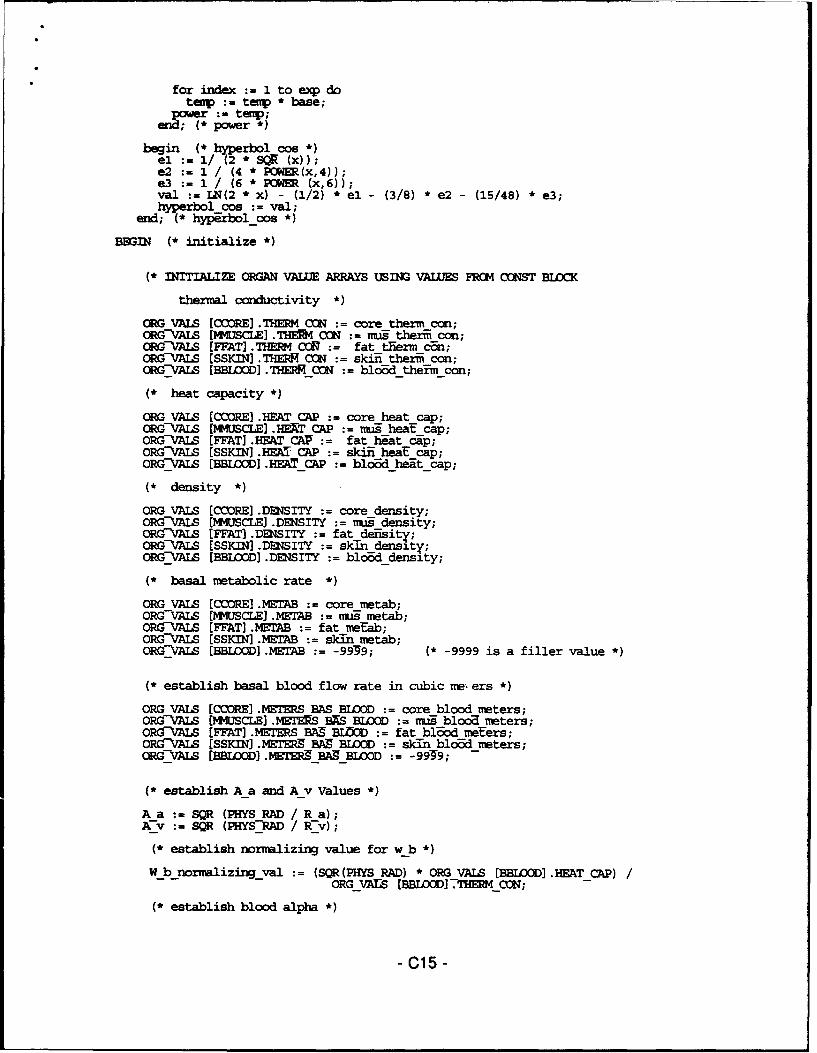
for index := 1 to exp dotenp : temp * base;
ower: temp;power *)
begin (* hyperbol cos *)el := 1/ (2 * SQR (x));e2 :- 1 / (4 * POWER(x,4 4;e3 : 1 / (6 * P (x,6));val := L(2 * x) - (1/2) * el - (3/8) * e2 - (15/48) * e3;hyperbol cos := val;
end; (* hypbol_cos *)
BEGIN (* initialize *)
(* INITIALIZE OGGAN VALLE ARRAYS USING VALUES FROM C(OST BLOCK
thermal conductivity *)
ORG VALS (COORE] .THERM CON := core therm cof;ORG-VALS E(WISCLE] .T CON -:= mu thermi con;ORGVAIS [FFAT] .THM CON := fat tierm can;ORGVALS [SSKIN .THERR CON skiii therm con;ORGVALS [BBLOOD]. THERM_ = bl~oddtheim con;
(* heat capacity *)
ORG VALS [CCORE .HEAT CAP := core heat cap;ORGVALS (MMUSCLE] .HEXT CAP := -- heat cap;ORG-VALS (F7AT] .HEAT CA1 = fat heat cap;ORGVALS [SSKIN] .HEAT CAP = skiii heat cap;ORGf ALS [BBILOOD] .HEAT_CAP = blod_heat_cap;
(* density *)
ORG VALS [CCORE] .DENSITY := core density;ORG-VAS [MMUSCLE] .DENSITY := mus density;ORG-VALS EFFAT .DENSITY := fat deisity;ORG-AIS [SSKIN] .DESITY = skin density;ORG-VAIS [BBLOOD .DENSITY = blo6d density;
(* basal metabolic rate *)
ORG VALS [CCORE] .MTAB := core metab;ORG-VALS [MMUSCLE] .METAB := nfs metab;OR-VAIS [FFAT) .METAB := fat me-tab;ORGVALS [SSKIN] .MTAB = skin metab;ORG-VrALS [BELOOD] .METAB -99-9; (* -9999 is a filler value *)
(* establish basal blood flow rate in cubic me, ers *)
ORG VALS [CCORE] METERS BAS BLOOD := core blood meters;ORG-VAIS [MMUSCLE] .METERS BXS BLOO nags blood meters;ORGVALS [FFAT) .METERS BAB BiC :- fat blood meters;ORG-\AALS [SSKIN] .METERS BA9 BIfLOM = skin blood meters;ORG-VAS [BBLOOD) .METER`9 BA BLOOD := -99-9; -
(* establish A a and A v Values *)A a SQR (PHYS RAD / R a);A_-v - SQR (PHYS-RAD /Rv) ;
(* establish normalizing value for w b *)
W_b_normalizing_val := (SQR(PHYS RAD) * ORG VALS [BBLOID] .HEATCAP)ORG VArS (BBLOOD] 71IM_CON;
(* establish blood alpha *)
-C15 -

BL ALPHA C RG VAIS [BBLMI. ¶I7~MW CCIN(ORUVALS (BBIflM] .DENSTTY * ORGVMLS [BBLDM(, .HEAT-CAP);
(* establish w b nrml array - basal blood flow rate in cubic meters~array rml, b i 1 array, THERMCON ARRAY, HEAT CAPARRAY,D 1S nJARRAY *) ...
(* N.B.subscripts for tissue data access represent the interfaceimmediately above the tissue
FUR I := 1 70 N DOBEGINI LOC PLACE(I);W-ARRAY [I] := ORG VALS [I LIC] .METRS BAS BIflCD;QARRAY PHYS (I] :-ORG VALS [I LOC] .?ETAB7T CM ARRAY (I] :RG VALSTI LOC] .THERM CON;HEAT CAP ARAY [I] ORG-VALS [I-LCI .HEAT CAP;DESTTY MRRAY [I] ORG VALS [I-1lCI .XDESTTY;W b nrmT [I] := W_ARRAY[IT * W_B 14RMALIZINGVAL;mDIT--
W ARRAY [N] 0.0;W-b nrml[N] 0.0;W-b-hrml [0] W b nrml [I];W--RPY [0] := W hAMY [ 1] ;TRERM CC_•ARRAY TO] := THERM CN ARRAY [1];
(* checking for w array values of zero so as to setua, u v, h a v, h v a to zero. ALL w array values
must-be zir6 for-u_a, u_v, h a v, h-v a to be changed *)
Wzero flag := true;
FOR I := 1 TO N DOIF W ARRAY [I] > 0 THE
Wzero flag := false;
K AVG 0.0;
FOR I 0 T0 N-I DOK AVG := K AVG + THERM CON ARRAY (I] *
(SQR(RADIAL DIST ARRAY [I+1]) - SQR(RADIALDISTARRAY [I]));
(* N.B.-------------------------------------------------------------------re-assign w array to W TISSUEREASN : necessity to add n-i tissue layers before interfaceadjustments have been made. In preparation for calculationof capillary data. Values are found at exact tissues locations,not one value greater than actual tissue location.
for i := 1 to N-i doW TISSUE [I] := w array [i+l];
w tissue[0] := wvarray [1];
(* apply equalizing formula on interface locationsp = (GAM1MA [i] * p- + p) / (I + GAMMA [i])
also determine B i-1 and ALPHAPROP arrays
FOR I := I TON DOIF I IN I INTERF3ZIES THEN
BEGINGAM :- GAMMA (I,H r ARRAY);THERM CON ARRAY [IT (GAM1 * THERM CON ARRAY [I-li +
THERM C1N ARRAY TI+lT) / (1 + GAMM)1;HEAT-CAP ARRAY [I] := (MW-* HEAT CAP ARRAY [I-1] +
HEAT CAP ARRAY [T+l]T / (1 + GAMM);DE2NSITY ARRAY [I] (QAMM-* DENSITY ARRAY [I-1] +
- C16 -

* DDNSITY ARRAY [I+1]) / (1 + GAMM);W ARRAY [I] :- (GAMM * W ARRAY[I-1] + W ARRAY[I+1]) / (I+GAMM);W-b nrml (I] := W ARRAYm * W B MRMALTZING VAL;
Q_0 AY PHYS [I] := (GAMM * Q AMY PHYS [I-IT +QARRAYPHYS TI+I]) / (1 + GAM);
END;
FOR I := 1 TO N DOBEGINBil UI] := (HI *LE•) / THERM CON ARRAY (I];
ALPHA PROP [I] := THERM CON ARRAY [I] / (DE2SITY_ARRAY [I] *REAT--CAP ARRAY [I]);
Q_ARRAY_nXml [I] := Q ARRAY-PHY-f (I] * SQR(PHYS RAD) /(N0*%LIZZ4G TEMP * BMO TIHEMCCN);(* b i li] := 0.0; *) -_
END;
(* establish U a and U v
IF W zero flag THENBMGIN -
U A 0.0;U-V :=0.0;Hf-A V 0.0;H-V--A 0.0;
ELSEBEGINUva:phys 2 * k avg sqr (phys rad) / In (2 * sqrt (r v/r a));uýV := 2 * kavg sqr (phys-rad) / in (2 * sqrt (r-a/rxv)) ;
U a (U a-phys * SR WYS RAD) / ORG VAIS[BBLOOD] .THEM CGD;_fv (Uvphys * SQR (PHYS-RAD) / ORG-VAIS [B]LOOD .T[MRCM) ;
U A DIV :=u a/ (n*m);
UfVXrIV =UV / (n*m);
(* establish H a v *)
H a vPHYS := pi* phys h z * 2 * K AVG /HYPERBOL cg T7 - (SQR( v - R a) / (2 * R a *Rv)));
"H A V := H A V PHYS-/ (PI * ORG VA1Z[BBLWC] .ITHERMCO *-- S-H Z)* A a;
"H V A H A V-P•YS / TPI * ORGVALS [BBLOOD] .THERM CON *- MT HZ) * Av;
{ reset u-a, u-v, h-ayv, h v a,}
h a v :- 0.0;h-va := 0.0;*. -
(* U V DIVIDED BY 5 T0 ACCOUNT FOR WNTERCEJRRENr HEAT XCCHANGE BgnqE
THE BLOOD VESSELS *)
IF (H VA <> 0) AND (H_A_V <> 0) MEN
U V := U V/5.0;TV DIV--- UVDIV / 5.0;
end; .
(* establish m a and mv arrays *)
- C17-

(* establish DDGMISIOML capillary loss *)
CAPILSUM := 0.0;
FOR I := 0 TO n-i DOCAPIL SUN := CAPIL SUM + W TISSUE [I] *
(SQR(PHYS-R_i[I+lT) - SQR(PHYSR-i[I]));
CAPILLARY LOSS := PI * PHYS H z * CAPIL SIM;START M a-: =CAPILTARYLOSS W -AXIAL_DIVD ;M a[iT 1T START Ma
FOR J ;= 2 TO M DO
M a[J] := M a[J-1] - CAPILLARYLOSS;
(* controlling the negative zero *)
IF M a [M] < CAPILLARY LOSS THEM-a [M] := 0.0;
M v [M] :- 0;F0R J : M-I MR= 1 DO
M_v [J] := M_v [J+l] + CAPILLARYLOSS;
(* establish Ba and Bv arrays *)
FOR J := 1 TO M DOBEGIN
B a [J] (M a [J] * SQR (PHYS RAD)) /(URG VALS [BBLOOD] .DESITY * PI * SQR (Ra) *
PHYS H z * BL ALPHA);ByV [J] (M v [JT WSQR (15HYS RAD)) /
(OMG VALS [BBUI] .D!SITY * PI * SQR (R-v) *PHYSH z * BL ALPHA);
END;
(* establish B iN.B. - B_!_C in data dump routine is B-i in the program code *)
B_i := (hc * PHYSRAD) / ORGVALS [SSKIN] .THERM_CON;
(*b i 0.0;*)
(* calculate dimensionless DELTA *)
SUM := 0.0;FOR I 0 TO N-I1 DO
SUM SUM + W tissue [I] * (SQR(RADIAL DISTARRAY[I+1]) -ýQR(RADIAL DIST ARRAY[I])T;
total a -2 * b-a [1] + Aa* a SUM -(AA* Ua + Ha_v);
total v:= -2 * b v [1] 2 * A v * SUM (AV *U v + H v a);total-:= abs (totalv);
if abs (total a) > abs (totalv) thentotal := alos(totala);
DELTA 0.4 / TOTAL
Idel tastSdelta not to exceed 0.0041
MAX DELTA : = DELTA;DELTA SEC := GC_DELTA;WRITErN;WRITELN;WRITELN ('ORIGINAL DELTA IN SECCNDS' ,DELTASEC:10:6);WRITEWI;WRITELN ('PROGRAM CALCUIATED MAX DELTA VALUE = ', MAX-DELTA 20:15);
- C18 -

WRITEI2N;DELTA : DELTA SEC * BL ALPHA / SQR (PHYS RAD)writeln ('pUSER-CALCULATED delta = ',DELTW:20:15);WRITELN;PAUSECrT;
(* loading numnric constants into variables of type XTDED *)
oe cOne;two := C two;three :.-c three;eight := c-eight;
(* normalize w tissue for use in t a t v calculationswhich require an absence of gammna Values used in interface
locations *)
FOR I := 0 T0 N-1 DOWTISSUE[I] := W_TISSUE (I] * WB _ORMALIZI1GVAL;
END; (*initialize *)
BEGIN (* main program *)clrscr;
WRITE ('HOW MANY TIMESTEPS ? ');READLN (LCVR);WRITELN;WRITEL&N;WRITE ('intervals at which to print tenperature data ? ');READLN (IlMrVAL);WRITELN;
ANATOMICALINPUTr (DIAM, LEN);
NUMDIVISICNS (COREDIVS, MUSCLEDIVS, FAT_DIVS, SKIN_DIVS, N, M);
WIDTHCALCULATIONS (H r CORE,H r MUS,H r FAT,H r SKIN, CORE MUS GAN%,MUS-FAT GAWi, FAT-S-IN GAWK, DIAM, LEN, -COREDIVS, MUSCLEDIVSPATDIVS, SKINDIVS);
ESTINTERFACES (I INTERFACES, I CORE MUS, I MUS FAT, I FAT SKIN,SRIN_SURFACE, CUREDTVS, MU9CLE-DIVS, PATThIVS, SKIN_DIVS);
CREATE ARRAYS (H r ARRAY, RADIAL DIST ARRAY, I CORE MUS, I MUS FAT,
- I PATSKIN, HrCORE, Hr MUS, Rr FVT, H-riSKIN);
DESTINATICN;
INITIALIZE;
TEINITIALIZE;
DATA DUMP;
TISSUE;
CLOSE (F);CLOSE (F2);CLOSE (W7T_DATA);CLRSCR;WRITE ('PROGRAM CCMPLETED -------- );PAUSE CRT;
ED. (*-main program *)
-C19-

2. VARSP.PAS
{GWBAL DECLARATION UNIT - INCLUDES CONST, TYPE AND VAR DECLARATIONS }
UNIT varsp;
INTERFACEUses CRT;
CONST{///////////II////// begin control point section \\\\\\\\\\\\\\\\\\\\\\\\\\\}
(* GC DELTA = 0.0 will allow program to determine delta value:.GC DELTA set to any other value will over-ride programcalculation of delta value.
N.B. - GC DELTA MUST BE GIVEN A VALUE IF ALL W VALUES HAVE BEEN9ET T0 ZERO.
(* DELTA IS A FULL TIME STEP - it will be adjusted later inthe tissue equations to be a half time step. In theblood equations DELTA will be a half time step for the firstiteration of the loop and a full time step on all subsequentiterations.
N.B. -- GCDELTA REPRESENTS DELTA IN SECONDS *)
GC DELTA = 1.0; (* PROGRAM MINIMUM = 0.0000015; *)
(* length and diameter must be in CENTIMETERS *)
GC LEN = 8.0;GC-DIA = 1.5;
(* control point for number of radial divisions *)
GC CORE DIVS = 3;GC-MUS 5IVS = 3;GC-FAT-DIVS = 2;GCOSKIN DIVS = 4;
(* control point for the number of axial divisions *)
GC AXIAL DIVS = 10;
(* control point for temperature values in degrees C *)
TA = 35; (* initial assignment for j=1 to j max-l values *)(* ta at j=1 held constant during program run at initial value*)
TV = 35; (* used for initial assignment at j max-2 to j = 1 values *)(* seed value at j max-i is ca culated by program *)
MESHTE1P = 35; (* used to set initial tissue temperature throughout mesh*)
NORMALIZING TEMIP = 37;
h 1 = b.09; (* units = Watt / meter squared / deg. C *)h-c = 5.17; (*7.02;*)
-C20 -
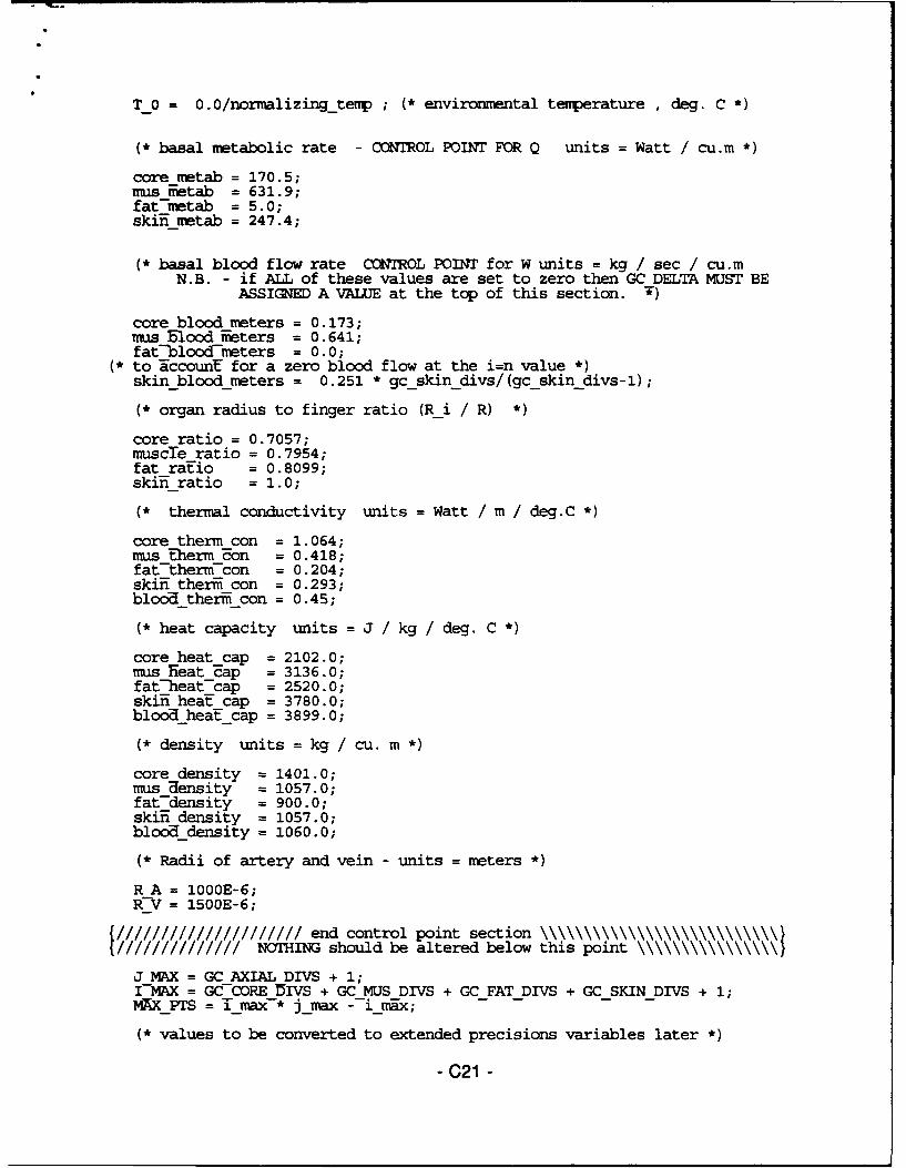
T_0 = 0.0/normalizingtemp ; ( environmntal temperature , deg. C *)
(* basal metabolic rate - CONTROL POINT FOR Q units = Watt / cu.m *)
core metab = 170.5;nus ifietab = 631.9;fat-netab = 5.0;skin metab = 247.4;
(* basal blood flow rate CONTROL POINT for W units = kg / sec / cu.mN.B. - if ALL of these values are set to zero then GC DELTA MUST BE
ASSIGNED A VALUE at the top of this section. W)
core blood meters = 0.173;bus Elood neters = 0.641;
fat-blood-mieters = 0.0;(* to NccounE for a zero blood flow at the i=n value *)
skinbloodmeters = 0.251 * gc skin divs/(gcskin divs-1);
(* organ radius to finger ratio (Ri / R) *)
core ratio = 0.7057;muscTe ratio = 0.7954;fat raEio = 0.8099;skin- ratio = 1.0;
(* thermal conductivity units = Watt / m / deg.C *)
core therm con = 1.064;mus Eherm Bon = 0.418;fat-therm-con = 0.204;skii ther'i con = 0.293;blood therzi con = 0.45;
(* heat capacity units = J / kg / deg. C *)
core heat cap = 2102.0;nus Heat-cap = 3136.0;
fat-heat cap = 2520.0;skiin heaE cap = 3780.0;blooahea7t cap = 3899.0;
(* density units = kg / cu. m
core density = 1401.0;mus Uensity = 1057.0;fat7density = 900.0;skiin density = 1057.0;bloCodensity = 1060.0;
(* Radii of artery and vein - units = meters *)
R A = 1000E-6;R-V = 1500E-6;
///////////////////// end control point section \\\\\\\\\\\\\\\\\\\\\\\\\\\}////////////// NOTHING should be altered below this point \\\\\\\\\\\\\\\\}
J MAX = GC AXIAL DIVS + 1;I MAX = GC-CORE DIVS + GC MUS DIVS + GCFAT DIVS + GCSKINDIVS + 1;MAX_PTS = T_Imax* jmax - 1_max;
(* values to be converted to extended precisions variables later *)
- C21 -

c two = 2.0;c-eight = 8.0;c three = 3.0;c-one = 1.0;
TYPEPTR TYPE = ATOM NODE;TOM-NODE = RECORD
TNFO : EXTENDED;NEXT, BACK : PTRTYPE;
END;
GRID = ARRAY [0..1_MAX, 1..JMAX] OF extended;BOUNDS = SET OF 1..I MAX;extended ARRAY = ARRAY [1..MAX PTS] OF extended;J ARRAY - ARRAY [1..J MAX] OF extended;I-ARRAY = ARRAY [0.. I-MAX] OF extended;A-TYPE = (A FIRST, A REG, A END, A EXTERNAL, A EXTERNAL END);RTYPE = (R--CENTR END, R CMNER RE5, R EXTERNALLEND, -
R-EXTERNAL REG, R INTERFACE REG, R INTERFACE END, R REG END);s TYPE = (s-REG cENMiNT,-S_-ExTERNP, sEN5, sEND_-TERNALT;C5 ORD = REMORD-
I LOC, JLOC : INTEGER;tomtemp-: extended;
END;L TYPE = ARRAY [1..MAXPTS] OF COORD;CUEF FIELDS = RECORD
MINUS, STD, PLUS : extended;END;COEF ARRAY = ARRAY [1..IMAX,1..JMAX] OF COEFFIELDS;VALUES = RECORD
THERM CON, HEAT CAP, DENSITY,METAB, METERSB•SBLOOD :extended;
END;ORGAN = (CCORE, MMUSCLE, FFAT, SSKIN, BBLOOD);VAL ARRAY = ARRAY [ORGAN] OF VALUES;STR-TYPE = STRING [20];
VARU PIR, U TRV, P, P1 : PTR TYPE;av step, half av step,t step, LCV R, INTERVAL :real;N . M, AXIAL 5IV9, ROW TIME, I, J,CORE DIVS, MUSCLE DIVS. FAT DIVS,SKIN-DIVS, SKIN SURFACE, D R, test,lcv,count, ICOREMUS, IMUS_FAT, IFATSKIN, COEFSUB INTEGER;
DIAM, LEN, H z, PHYS H z, RAD, PHYS RAD,PHYS LEN, U a, U v, v, H V A, H--A V PHYS,DELTA, MAX DELTA. DELTA-sec,--A-a, A v,BL ALPHA, W b normaliziiig val,-B 1, CAPIL.ARY LOSS, U_aphys, U_vphys,START M A, CAPTL SUM,H r CURE, H r MUTJ, H r FAT, H r SKIN,CZRZ MUS GAv*A, MUS FAT GANMA, 'AT SKIN GAMMA,CORE-WIDTH, MUS WIDTH, 'PAT WIDTH, SKINWIDTH,CORE-MUS BOUND,-MUS FAT BOUND,FAT _KIN-BOUND, SKIN SURFACE BOUND, K AVG,one, two, three, eigHt, zerou a div,-u v div extended;
I_INTERFACES, CORESET, MUSSET, FATSET, SKINSET : BOUNDS;
RADIAL DIST ARRAY, H r ARRAY, W ARRAY, W TISSUE,PHYS R--i, PHYS H r AffRY, W b rnml, Q ARRAY nrml,THERM ZMN ARRAY,--HAT CAP AMRY, Q_ARRAYPHYS,DENSITY_ARRAY, ALPHA_'PROP_ B i-l : I ARRAY;
- C22 -

A NODE : A TYPE;R-NODE : R-TIYPE;S_-ODE : STYPE;
B a, B v, M a, M v,T-Y, T--A, T--A baF, T V bar,t-a noate, t-vhnode, 3ola t a node, old-t v node JARRAY;
TE4P_GRID, HALFGRID : GRID;
LOCATE L_TYPE;
f,f2,OUTDATA: TEXT;
ORGVALS : VALARRAY;
RESP2, GRAPHRESP CHAR;
tanflag,uw_zeroflag boolean;
FUNCTION GAMMA (I VAL: INTEGER; VAR H r ARRAY : IARRAY) extended;PROCEDURE PAUSE CKT;PROCEDURE DERIVE CENTER TEMP (VAR DEGREES :GRID);PROCEDURE DUMP HFLF ARRAYS;PROCEDURE DUMP-T ARRAY (STEP VAL REAL; DEGREES : GRID);PROCEDURE CALC--'T TV half (STEP : EXTENDED);
IMPLEMENTATION
------------------ UTILITIES .........---
FUNCTION GAMMA (IVAL: INTEGER; VAR H_r_ARRAY : IARRAY) extended;
{ ....... returns the GAMMA value for any I location in the mesh......)
BEGINIF I VAL >= N THEN
GP4 := 0.0ELSE
IF I VAL = TEENGC-1VIA := 1.0
ELSEGAMA:= Hr_ARRAY[I_VAL] / H_r_ARRAY[I_VAL + 1];
END;
PROCEDURE PAUSECRT;
{ .............. halts screen output scrolling ......................... }VAR
AGAIN : CHAR;
BEGINWRITE ('PRESS ANY KEY TO CONTINUE :AGAIN := READKEY;WRITEIN;CLRSCR;
END;
PROCEDURE DERIVECENETERMP (VAR DEGREES :GRID);
- C23 -
{ establishes center temperatures at t [o,j]"**** N.B. this procedure REQUIRES A MINIMUM OF 2 RADIAL DIVISIONS }
VARJ, I : INTEGER;
BEGINFOR J := 1 TO M DO
DEGREES [0,J] := DEGREES [2,J] + 1.5 *(DEGREES [1,J] - DEGREES [2,J]);END;
PROCEDURE DUMP_HALFARRAYS;
{...... prints ta,tv arrays ....... }
VARJ val : INTEGER;
BEGINCLRSCR;WRITELN (F, 'TIMESTEP = ', HALF AV STEP 5:2,************************** I ) -
WRITE (F,'T A');FOR J VAL := 1 TO M-1 DO
WRITE (F,JVAL:3,')',TA NODE[JVAL] * NORMALIZING TE4P:7:3);WRITELN (F) ;WRITELN(F);WRITE (F,'T V');for J VAL := 1 to m-1 do
wrTte (f,j val:3,')',t v node[jval] * NORMALIZING_TEMP:7:3);writeln(f);END;
PROCEDURE DUMP_T_ARRAY (STEPVAL : REAL; DEGREES : GRID);
{... prints two dimensional tenperature matrix or halfstep matrix.. }
VARI,J : INTEGER;
BEGINWRITELN (F);WRITELN (F, 'TEMPERATURE ARRAY AT TIMESTEP ', STEP VAL:7:2, '(end/ext) ':42);FOR I := N DOWNTO 1 DO
BEGINWRITE (F, 'I=',I); *)
FOR J := 1 TO M DOWRITE (F, DEGREES [I,J] * normalizing tenT:7:3);
WRITELN (F);
END;WRITELN (F);pause crt;
END;
PROCEDURE CALCTA TV half (STEP : EXTENDED);
{ .... calculates ta bar[j] and tv bar[j] in preparation fors vector caTculation ......................... }
- C24 -
* VARSUM1, STUM2, SUM3,W VAL, HH aa vv,T -vplus, Bvy_plus, a, b. TEM1, DELTA VAR extended;l.J-Val - : INTEGER;fir~t,second, third,answer extended;
BEGINIF STEP = 0.0 THEN
DELTA VAR = DELTA / 2ELSE
DELTA VAR = DELTA;
FOR J VAL := 2 TO M-l DOBEGTN
(* CALCULATE T A BAR *)
SUM: 0.0;SUM2 := 0.0;SUM3 0.0;
FOR I := 0 TO N-I DOBEGIN
W VAL WTISSUE [I];
SUMI SUM1 + W val * (SQR (RADIAL DIST ARRAY[I+1]) -
SQR (RADIAL DIST-ARRAY[I]));SUM2 SUM2 + (TEMP GRID[I,J VAL-IT + TEMP GRID [I,JVAL]) *
(SQR (RADIAL DI9T ARRAY[I+l]) --SQR (RAUIAL_ ISTARRAY [I]));
SUM3 SUM3 + W VAL * (TEMP GRID [I, J VAL-1] +TEMP GRID [I,J VALIT * (SQR (RADIAL DISTARRAY [I+1])
-- SQR (RAD-IALDISTARRAY [I]))7;END;
(* FINAL FORMULAS *)
(* T A is the t a BAR value at the previous full time stepthe same is Erue with regard to TV and tvBAR *)
T-a-bar [JVAL] :=t-a [j-val] + DELTAVAR* (( -two * BA [JVAL-1]+
AA *SUM1 - AA * UA - H AV) *T A [J VAL] +(two *B A [J V-AL-1] 7 A A T RX1) *--T A Rode [J VAL-1]+ 0.5 * •_A *--U A * SUM2--+ H A V * T V-[U VAL]) ;
END; (* J-LOOP *)
(* CALCULATE T V BAR *)
FOR J VAL := 2 TO M-1 DOBEGIN
SS1 := 0.0;SUM2 := 0.0;SUM3:= 0.0;
FOR I := 0 TO N-I DOBEGIN
W VAL W TISSUE (I];
SUMI SUM1 + Wval * (SQR (RADIALDISTARRAY[I+l]) -
-C25 -

SQR (RADIAL DIST ARRAY [I]));SUM2 :SI42 + (TEMP GRID(I,J VAL+IT + TE4P GRID [I,J_VAL]) *
(SQR (RADIAL DI•'g ARRAY[I+1]) -SQR (RADIAL 15IST ARRAY[I]));
SUM3 SUM3 + W VAL * (TEMP GRID [I, J_VAL+1] +TEMP GRID5 [I,J VAL])-*
(SiR (RADIAL-DIST ARRAY [I+l])- SQR (RAMIAL DIST ARRAY [I]));
END; (* I-LOOP *)
T v bar[JVALI := t v [j val] + DELTA VAR * ((two * B V [J VAL-i]-two * A V-* SR1- A V * U V - H V A) * T V-[J VAL] +
(-two * 9 V [J VAL-1]-+ A V--* SUMi)-* T V NODE TJ VAIL-l] +0.5 * AV * TV * SUM2 +4HVA * T A [1 VALI + 0-5 * AV *SUM3) ;...
END; (*JVAL*)
(* calculate t a node and t v node *)for j val := 2 to nm-i do
t-a_node [j_val] := 2 * t_a-bar [jval] - t_a node [jval-l];
SUM = 0.0;FOR J VAL := M-1 TO M DOFOR I:-- 1 TO N DO
SUM) := SUM1 + HALF GRID [I,JVAL];T_V_NODE[M-1] := SUM1 /('[* N)
for jival := m-i downto 2 dot_v_node [j_val-l] := 2 * t v bar[jvail - t v node [j_val];
END; (* calc ta tv half *)END.
-C26 -

3. TISUESP.PAS
Uniit tisue _sp;
interfacePROCEDURE TISSUE;
implementationuses var_sp, phys_sp, crt, dos, printer;
PROCEDURE TISSUE;VAR
ORIG A rODEF, ORIG A zCOEF COEFARRAY;
PROCEDURE AXIAL DIR ( I VAL, J VAL : INTEGER;- AR--J_MINM FORM, J_FORM, JPLUSFORM : extended);
{... ... imports the I and J coordinates, identifies the typeof node using enumerated data types and calculates threecoefficients at the given I,J location to fill theORIG A z COEF array used for the traversal in theRADIlt7-dfrection .......................................... }
VARHEAT_DENFRACr, ASQRD, FRACT, W_U_A, temp-w uua extended;
BEGIN(* establish node type *)
IF J VAL = 1 T71SNODE := A FIRST; {pt. 0}
IF J VAL = M TMIF--I VAL <> N THENA ODE :=A E {pt. 4,6,7}ELSEA M)DE := A EXTERNAL END; {pt. 5}
IF (J-VAL <> M-AND (J_VAL <> 1) THENIF--I VAL <> N 7HEN -
A-NCDE A REG (pt. 1,3}ELSE--ANDE :=AETERNAL; {pt. 2)
(* preliminary calculations *)
A SQRD := (BL ALPHA / ALPHA PROP [I VA]) * SQR (LEN/PHYS RAD)MAT DEN FRACT = (ORG VALSTBBLOOD] .DENSITY * ORG VALS [BE ]I .MEAT CAP) /
- --ENSITY ARRAY [IVAL] * HEAT_CAPARRAY [IVALT);FRACT := one/ (A_SQRD * SQR(H_z'T) ;
WUA :W= Wb_nnl [I_VAL] + U_A div + U_v_div;
(* setting w, u a, and u v at external skin level to 0.0 *)tenp w ua := 07.0;
(* FINAL CALCULATIS *)
CASE A NDDE OF"A FIRST : ;
"A REG : BEG3IJ MINUS FORM := FRACT;J-PORM --= -one* (two * FRACT) - (HEAT_DEN FRACT * (W_U_A / two));J-PLUS FORM := FRACT;
EN•;
-C27 -

* A _M1@L : BEGINJ MIUS FO•M -= FRACT;J-FORM T= -two * FRACT - (HEAT DER FRACT *
-(three * tenp W U A) /eightT;JPLUSFORM V ~~IMYT
EN",D;A ED : BEGIN
J M•US FURM :- tw FR * AMJ-FORM -= -two *FRACT * (one + H z * B i I [I VAL])
- ((HEATDEN FRACT T W b i riii [I-VAL) /two);J PLUS FORM := 0.0; -
A _XTERNAL END BEGINJ MINUS FORM = two * FRACT;J-FORM -two * FRACT * (one + H Z * B i 1 [I VAL]) -
(three * HEAT DEN FRACT * W b find 11_VAL] -/ eight);J PLUS FORM := 0.0;END; -
ED; (*CASE*)END; (* axial dir *)
PROCEDURE RAD DIR (IVAL, J VAL: INTEGER;VAR I MINUSFORM, IFORM, I_PLUS•FORM : extended);
{.......... imports the I and J coordinates, identifies thetype of node using erumerated data types and calculatesthree coefficients at the given I,J location to fill theORIG A r COEF array used for the traversal in theSECCM -D-TAVERSAL ............................................. }
VARALPHA PORM, HEAT DEN FRACr,FRACTI FORM, GAMM, HR__I, R_I-,tenp_form : extended;
BEGIN
(* establish node type *)
IF (J VAL = M) THENBEG3N
R NDE := R REG EM; {pt. 4}IT (I VAL TR I MUERFACES) THEN
R MDE := R--INTERFACE_END; {pt. 7}IF (1 VAL =I)n
R 14DE := R CN'IR END; {pt. 6}IF I-VAL= N TR -
R-DE := R_-ETERNAL_END; {pt. 5)
ELSEBEGINIF I VAL = THEN
R OE R CENTR REG; {pt. 1}IFTVAL=NTHEN -
R RMDE := R EXTRNAL REG; (pt. 2)STIU VAL <> 1) AND (I-VAL <> N) THENR N_ E := RINTERFAC_REG; {pt. 3)
END;-
(* preliminary calculations *)
ALPHA FORM := ALPHA PROP [I VAL) / BL ALPHAHEATDEN FRACT :- (URG VALSTBBLOD] .bDOSITY *
ORG VALS[BLOOD] .HEAT CAP) /(DENSITYARRAYC[I_VAL] * HENT CAP ARRAY[I VAL]);
(* H R ARRAY AT THE 1 LOCATIIC MKST USE THE VALUE AT H R ARRAY [2] *)
IF I VAL = 1 THENBEGIN
FRACT two / SQR(H_R_ARRAY (2]);
-C28 -

GAMM :mGAMMA (2, H R ARRAY);
H R I := HR ARRAY 12T;
ELSEBEGIN
FRACT :- two / SQR(H R ARRAY[I VAL));GAMM := GAMMA (I VAL, R R ARRAY);H R I := H_R ARRAY [I VLT;
FoR w b b_nr.[I_VAL] + U a_div + U v_div;
(* setting w, u a, and u v at external skin level to 0.0 *)tefp_form = 0.a;
RI := RADIAL DIST ARRAY [I VAL];
(* final calculations *)CASE R NODE OF
RCMTE REG : BEGINS -- I MINUS FORM 0.0;
IFORM- = -one * ALPHA FORM * FRACT - (HEAT_DEN_FRACT* FORM / t%6);
I PLUS FORM = ALPHA FORM * FRACT;
RINTERFACEREG : BEGINI_MINUS_PFRM ALPHA FORM * (one / ((1 + GAMM) * HRI))
• (twoTGAM / H R I- 1 / R I);I-FORM := -one * ALHA FORM * -Tcie / H R IT *
((two * GAMM / RR I)- (one- GA-M)--/ RI)- (HEAT DEN FRAZT--* (FORM / two));
I PLUS FORM : L= XPB FORM * (SQR(GAMM) /(HRI * (one + G4M))) *(two / HR_I + cne /RI);
END;R EXTERNALRBG : BEGIN
IMINUS FORM - ALPHA FORM * FRACT - (HEAT_DEN FRACT-- -- *temp_•ORM / eight);IFORM := -one eALMP FORM * {FRACT + (one + (two / H R I))
* B I) (HEAT DEN FRACT * (three * tenp_FORM/eigHt));I PLUS FON: 0.0;END;-
R REG_-ED BEGINI MINUSFORM ALPHA FORM* (cne / H R I) *
(one / H-R I - one / (two T R I));I-FORM := -one * ALPH rORM * FRACT - (HEAT DENFRACT *
Wbnnl [I VAL] /two);IPLUSFORJ'-:- ALPHA MRM * one / HR I * (one / HRI +
one /-(two * RI));END;
RCENTR _D : BEGINI -- I FUSORM := 0.0;%-FORM = -one * ALPHA FORM * FRACT - (HEATDEN FRACT *
W bnrml I VALT / two);I PLUS FOR := A FORM * FRACT;
R INTERFACE END BEGIN-IMINUSPFORM ALPHA PORM * (one / ((one + GAMM) * H R I)) *
(two * GAMM / H R I - cne / R I); --I PRM:= -one *ALPHA PORM * (oe7HR I)* -
-- ((two * GAMM / H R I)-?r (cn~e--G•" ) /R I)- (HEAT_DEN FRArT-* W_b_nnrl (I VAL] 7 two);
IPU.S FOR := ALPHA FORM * (S)(GAMM) /- -- (HR_I * (oe-+ GAMM) (two _RI + cne / RI);
END;R-EXERNAL END :BEGIN
I MINUSFORM := ALPHA FORM * (two / SQR(H R I)) -(HEAT DEN FRACT * W b nfnf [I VAL] / eight);
IFORM := -one * ALPHAVFORP4 * (FRACT+--+-(one + two / H_R_I)
-C29 -

*Bi) -(three *HFAT DENFRAcrW b-nxml (I VAL] eight-);
I PLXS FORK-:, 0.0;
END; (* rad dir *)
PROCEDURE SVECTOR (IVAL, JVAL : INTEGER; VAR SVECT - GRID);
{....... calculates s vector coefficient in preparation formesh traversal ......................... }
VARA, W FORMULA, T FORMULA,HEAT-DEN FRACT,-ALPHA FORM, ASQRD,H R,- NCE VAL : extedided;te-mp_u v :Extended;
BEGIN
(* estblish node type *)
IF (J VAL = M) AND (I VAL = N) THENS NODE =S _D EXTERNAL
ELSE -EIF (J VAL = M) THEN
S lDE :2 SEDELSIEIF (I VAL = N) THEN
S RDDE := SEXTERNALELSES_•ODE := SRFGCNERIT;
(* S VECTR CALCt1ATIONS - PRELIMIARY FORMULAS *)
A SQRD := (BL ALPHA / ALPHA PROP [I VAL]) * SQR(LEN/PHYS RAD);AnPHA FORM : --ALPHA PROP [I-VAL] / RL ALPHA;HEAT _EN FRACT := (ORGVALSTBBILOD] .DESITY *
ORG VAIS (BBLOOD] .HEAT CAP) /(DENSITYARRAY(I_VAL] * HEAT_--CAPARRAY[I_VAL]);
H_r := H_RARRAY [I VAL);
if s node = s external thenbegin
temp u v := 0.0;w fo--iia : 0.0;
en'aelse
W-FORMUA :=W bnrml (IVAL] + U A div;
IF J VAL = M THENNODE VAL := T A NDE[J_VAL -1]
ELhSE - ----NODEVAL := T_A_NO3DE [JVAL];
TFORMULA := NODE_VAL - (TEMP_GRID [I VAL-I, JVAL] / eight);
(* S VECIOR CALCULATIONS - FInAL FORMULAS *)CASE7S NODE OF
SRG _CENTER INTS VECT (I VAL, J VAL]
-- HEAT VEN FRA * (Q ARRAY nrml 1I VAL) +W FORMULA * T A-M [iJ VAL) +-7U V dIv * T V-NODE [J_VAL]);S EXTERNqAL -- :...
S VECT (I VAL,J VAL] :=- HEAT-D ACT * (Q ARRAY nrml [I VAL] +
W_FORMULA * TFORMLA +te.p U V * TT V NODE [J VAL] -TFEP GRID [T VAL-1, J VALT 7 eightT)-+ ALPHA-FORM *
(one +-two/ HA) * BI--* T_0;
-C30 -
S_•~S--NDS VECT [I VAL, J VAL]HEAT DEN FRACT * (Q ARRAY nrml [I VAL] +
W-b nd [I VAL]-* T A-NDE - val-l]) +(' wo * BlI VALV]-* T_0) 7 (A_SD *HZ));
-- EXTERL S VECT [I VAL,J VAL]HEAT DE FRACT * (Q ARRAY nrl (I VAL] +WE nrifil [I VAL] I T FCRLA )
ALPHA FO9R * (one ; two/H R) * B I * T 0 +(tvo--* B i (I VAL] * TU) /(A-SQRD HZ,;
END (* CASE *);END; (* s vector *)
PROaMRE ESTABLISHCOEFARRAYS;
{...... creates arrays of axial and radial coefficients usingarrays of records ........................ }
VARI, J : INTEGER;
BEGIN
(* establish arrays of coefficients in the radial directionn.b. -- each I value references a record comtaining
three coefficients found in arrays imat, i mat2,ORIG A z. *)
FOR i n downto 1 doFOR j = m downto 2 do
RAD DIR (I,J, ORIG A r COEF [I,J].MINUS,ORIG Ar COEF--[T, ) .STD, ORIG A rCOEF [I,J] .PLUS);
FOR I n downTO I DOFOR J := m downto 2 do
AXIAL DIR (I,j, ORIG A z COEF UI,J]1.MINUS,ORTG A zCOEF[I,JT. IS, ORIG A zCOEFEI,J] .PLUS);
END; (* establishcoef arrays *)
PROEDURE TRAVERSE;
{...... traverses the mesh in the radial and axial directionsusing TFRIW ALGORITHM...................
VARINDEX, X, start, prey_total, total INTEGER;S PTR, S TRV,C-PTR, IC-RY,A -PTR, A-TRV,B-PTR, B-TRV,Cy Pm, CI TRy,Al-PTR, AI-TV,BI- PR, BI TRV,CJ-PTR, Cj-TRV,AY-PTR, AO-TRV,BJ-PTR, BJ-TmV,
DPMR, D_ý7, kEW~E :PTRTYPE;
S V COEF : GRID;DM, DUMP3 : CHAR;
PROCEDURE UPDATETISSUE_1 (VAR TISSUE GRID);
-C31 -

VARI-OULNT : INT3EMR;
FOR I CUNT 1 TO N DOTISSUE [I_CONT,I] :- 30 / NORMALIZING_TEWP;
END;
PROCDRE TnMiaS_ A-W (SYS_SIZE :INTEGER);
VARI, ii,jj,z : INTEGER;
P PTM, P TRV,OTPMR, M1 TRV,B 1 Qi, BK 01 TRV,-:up, BK__•_TRV, NEDE : PTR TPE;
PROCEDRE CALCPRIhEDPRIME;VARI : INTEGER;
lOFMI : EXENED;BEGIN
NEW (NEWNDE);NExkmE^.INFO B FTRA.INFO / A_PTRR.INFO;NEWNODEA.NEXT NTL;NEWNDEA.BACK f NIL;P PTR := ME;P TRV P PTR;BK P NIl;NEW (NEWNDE) ;NEWNDEA. INFO D PTR.INFO / A_PA.INFO;NEP&=E^ .NEXT NTL;NEWNME'.BACK NIL;Q1 PTR := NEWKNDE;Q-I--RV := Q1 PTR;BK-Q = NIL;A TRV A P.RANEXT;C-TRV = -pTR•m C .NEXT;"BmRV = B--PTRA .NE;D-TRV D-PTRA.NEXT;FOR I 2--'O SYS-SIZE DOBEGIN
FORM1 := A TRVA.INFO - C TRVA.INFO * _ INFO;NEW (NEWNWE) ;NEWNDEA.INFO B TRVA.INFO / FORM1;NEltqODE^.NEXT :NTL;NE4NOMA.BACK := P TRV;P TRV'.NEXT := NEWHODE;P"TRV P TRW.NEXT;NEW ( D) ;NEWODEA .NEXT : NIL;NEWNDEA.INFO := (D A.IN; - CT•.JFO * Q_•TRVA.IN) / F ;IMM .A BACK = QI-TRV;Qi TRV. NEXT NEWH=DE;QlTV := Qi TRVA.NEXT;A TRV :=A TR4.NEXT;C-TRV :=CTRV.NEXT;BTRV:= B TRV4.NEXT;D-TRV:= D_TR.NEXT;
BK P := P TRV;BKfQ1 .1_TRV;
END;
PRO~~]RECALC VALS;VAR
I : INTEGE;
-C32 -

BEGIN
NEITMWE .IFO -= BK Q1A.INFO;NEWNME .NEXT = NIL;U PTR :. - E;BK Q1 TRV := BK Q1'.BACK;U TRV-':= U PIR;-BKPTRV :Z BK PA.ACK;
(* U IS BEING FILLED VIA FIRST NODE INSERTICN *)
F-R I := SYSSIZE-1 DCWN 1 DOBEGINNEW (MOME);NEwDE^.IN := BK Q1 TRvA.INFO - BK PTRVJ.INFO * U _VA.INFO;NEWMEA .NET UPMR;U PR := ETODE;BE Q1 TRV BK Q1 TRVW.BACK;BK-P TRv BK P MrV.BAcK,;u -= uptr7-34D7
END;
BEGIN (* T7MAS ALG *)
MARK (p) ;NEW (U PTR);U PTRA.-INFO := 0. 0;Tf-PTA.NEXT :=NIL;NEW (Q1 PTR) ;Q1 PTR -INFO 0.0;Q1--PTRA.NEKT = NIL;NEW (P Tm) ;p PR.-NFO 0.0;
-PRA.NEXT := NIL;Uf-TRV := U PTR;QT TRV :0 •1 PTR;P TRV= P PTR;FUR I :=2 TO SYS SIZE DOBEGIN
NEW (NEWNDE);NEKNDE^..INFO 0.0;NEWN!DEA.NNEXT NIL;U TRV^.NEXT := NEWNODE;U-TRV := U TRVA.NEXT;NEW ( N ) ;NEWNDE .INOI 0.0;NEWNDEA.NEXT := NIL;Q1 TRVý.NEXT NEWNODE;Q1-TRV :- Q1 TRVA.NEXT;
NEW(NE{ DE) 7NEWNDE.INFO := 0.0;NM DEA.NEXT := NIL;P TRVý.NEXT := NEW•E;P-2v := PR7VA.NEXT;
CAL CPRIME DPRIME;CAI• VALS;-
END;
PROCDRE SECtZD_TRAVERSE AXIAL;
{... traverses the mesh in the axial direction moving necessarycoefficients from record storage structure into extended
precision arrays for access by Thomas' Algorithm ........ }
VARI,J,j find : INTEGER;IM _TEMP, I-MXTM, HALF_DELTA extended;
-C33-
• INDEX : INTER;
BEGIN
MARK (Pl);S PTR :=NIL;C P'rR NIL;A-P-R := NIL;B-PTR :- NIL;CT PR :=NIL;AI-PTR := NIL;BI-PTR = NIL;DPf := NIL;
half delta delta/2;T0TAL := -0;PREV TOTAL 1;FOR I := 1 to n do
BEGINX := 0;FOR j := 2 to m do
BEGINX := X + 1;(* load coefficient arrays *)
SVECTOR (I, J, SV COEF);
NEW (NEWNDE) ;
NEWDE..INFO:= S V COEF (I,J] * HALFDELTA; (* S[X]*)NEWDE.NEXT = NTLTIF S PTR NIL T71
BECINS PTR NEWNODE;S-TRV := SPTR;
ELSEBEGINS TRV^.NEXT := NEWNODE;STRV := S_TRVý.NEXT;
NEW (NENOKDE);NWNOEA.INFO := -l * ORIG A z COEF [I,J] .MbTFJS * HALF DELTA; (*C[XI*)NEWNEA .NEXT = NIL;IF C PTR = NIL TMENBEGIN
C FIR := NE DE;C-TRV := C_PTR;
ELSEBEGINC TRV .NEXT NEWNODE;CTRV := C_TRV.NXT;
NEW (NEWNDE)NEWNDEA.INFO := -1 * ORIG_ A zCOEF [I,J) .STD * HALF DELTA + 1; (*A[X]*)NEWNODEA.NEXT := NIL;IF A PTR = NIL THENBEGIN
A PIR := NEWNMDE;A-TV := A_PTR;
ELSEBEGIN
A TRVA.NEXT := NEWNODE;A7TRV A_TR. NEXT;
NEW (NEWNODE);NEw DEA.INO: -I * ORIGA zCOEF [I,J] .PLUS * HALFDELTA; (* B[X]*)
-C34 -

NENNOI)A.NEXT := NIL;IF B PTR M NIL THE
B PTR := NEW E;B-TRW :- B_PM;
ELSEBEGINB TRV.NEXT := NDE;B-TRV: BT .NEXT;
NEW (NEWDE);NECDE'. INFO := ORIG A r COEF [I,J1 .MINUS * HALFDELTA; (* CI[X)*)EME^.NET := NIL;---
IF CI PTR = NIL THENBEGIN'-CI PM := NEWNDE;CI-'RV := CI_PM;END-
ELSEBEGIN
CI TRV^.NEXT := NEWNDE;CI-TRV := CITRV.NEXT;END;--
NEW (NEWNOE);NEWDDE*^.INFO := ORIG A r COEF [I,J1 .STD * HALF DELTA + 1; (* AI[X])NEWNDE*.NXT := NIL;IF Al PTR = NIL THENBEGIN`-Al PTR := NEWMDE;AI-TIV := AIPTR;
ENDELSEBEGIN
AI TRVA.NEXT NEWNDE;M-TRV := Al TRv .NExT;
END;--
NEW (NEWNODE);NEWNCDE^.INFO := ORIG A r COEF [I,J1 . PLU * HALFDELTA; (* BI[X] *)NEWN)DE .NEXT := NIL;IF BI PR = NIL THENBEGIN-
BI PTR : NEWNDE;BI--TRV := BIPTR;END
ELSEBEGIN
BI TRV^.NEXT := NEWNDE;BI-TRV := BITRVX.NEX,.;EN]D;--
(* calculate constant term *)
NEW (NEWNCDE) ;NEWNODE*.NEXT := NIL;IF D PM = NIL MEN
"D PTR := NEWNCDE;"DTRV := D_PTR;
ELSEBEGIN
D TRVW.NEXT := NEWNDE;D-'TRV := DTRV*.NEXT;
IF I = 1 THEDTRV*.INPO := AI TRV*.INFO * HALF GID [I,J] +
EB_TRV .TFO * halfgrid TI+l,J] + S_TR-W.INFO
-C35-
ELSEIF I - N THEN
D_¶IRVt.]F := CI TRV^. 1260 * HALF GR.ID [ I -1,J] +_ ITR.IN1-,* HALF-GRID [I, JT + SmV.INM-
D_T'.WO :- CI W.n. * halfgrid [i-1,j] +Al 7W. 1160 *-HAL GRID [I,J] + bi T,.InUO
*• afid [i+l,jT + STR..n ;-
(* adjust d[x] for j = 2 position *)
IF J = 2 THENDTRVW.INMD := DTRVA.INFO - CTRW.INFO * HALFGRID [I,1];
(* save I,J locations to facilitate 1placing of newtemperatures in proper locatlcs *)
TOTAL := TOTAL + 1;LOCATE (OTAL]. I LOC := I;LOCATE [TOTAL] .J-LOC =J;
END; (* JLOOP *)
THOAS ALG (x);
(* move temperatures generated by TASALG tolinear array locations ,)
U TRV UPTR;FR INDEX --= PREV TOTAL T0 TOTAL DOBEGIN
LOCATE [INDEX] .TCM TEMP := U TRV!.INFO;u TRV := U_TRv. NX;
REEPRELEASE (P);RELEASE (P1);PREV TOTAL := PREV TOTAL + X;
END; (* I-LOOP *)
(* move temperatures generated by THCHAS ALG toproper mesh locations *)
FOR INDEX := 1 TO TOTAL DOHALFGRID [LOCATE[IlDEX].ILOC, LOCATE [IDEX] .J LOC] locate (INDEX) .tomtemp;
DERIVECETER TEMP (HALFGRID);
END;
PROCEDRE FIRSTTRAVERSERADIAL;
{... traverses the mesh in the radial direction moving necessarycoefficients frcvi record storage structure into extendedprecision arrays for access by Thcmas' Algorithm .......... }
VARI,J,J FIND : INTEGER;J MA)CTEMV,HALF DELTA extended;t-, tj-- integer-INDEX :INTEGER;
BEGIN
S PIR2 NIL;C-PTR NIL;A-IR := NIL;B-PTR NIL;CU PTR := NIL;AJ-PTR := NIL;BJ-PTR NIL;DITR := NIL;
-C36-
MARK (PI);HALF DELTA := DELTA / 2;PREV-TOTAL :=1;TOTAL :- 0;FOR J :- 2 TO m DO
BEGIN
X := 0;FM I := 1 to n DOBEGIN
X := X + 1;
(* load coefficient arrays *)
S VECTCR (I, J, SVCOEF);INW (N C) ;E);NE1WMM.INFO := S V COEF[IJ1 * HALFDELTA; (* S[X] *)NEWNCVCE. NET :- MTL7
IF S PTR = NIL THEEMIN
SPTR :-u NEN E;S-TRV := SPTR;
ELSEBEGIN
S TRV^.NE=T := NEMODE;S-TRV := STV'.NEXT;
NEW (NEWCDE);NEW E.INFO := - * ORIG A r COEF [I,J] .MINUS * HALF_DELTA; (* C[X]*)NEW .NEXT NIL;IF C PTR = NIL THENBEGMN
C PTR := NEWACE;C'TRV -= CFPR;Ew-
ELSEBEGIN
C TRVA.NEXT := NEWNDE;CTRV := C_RV^.NXT;
NEW (NEWNCE);NEWE.INFO := -1 * ORIG A rCOEF [I,J1 .STD * HALF DELTA + 1; (* A[XJ *)
NEW EA.NEXT NIL;IF A PTR = NIL THENBEGN
APTR := NEW•DE;A-TRV := A_PR;mv--
ELSEBEGIN
A TRVA.NEXT := NEWNCDE;A--TRV := A TRV'.NEXT;
NEW (NEWNME);NE•NDE .IMFO -1 * ORIG A rCOEF [I,J] .PIUS * HALFDELTA; (* B[X]*)
NEWNCCE.NET := NIL;IF B PTR = NIL THEN
B PTR := CE;B-TRV B_-PR;•qD-
EMSEBEGIN
B TRVA.NEXT : NEW E;B-:RV : B TRV.NEXT;
-C37 -

NEW (NEWNOE);NEME.INO := ORIG A z COEF [I,J] .MINUS * HALFDELTA; (* C[J]*)NEVRCME.NEXT := NIL;IF CJ PM - NIL THENBBWIN-
CJ PTR = NEW E;CJf_1RV 3 CJPrR;END
ELSEBEGINCJ TRVA.NEXT := NEWNME;CJ-'TV := 03_TRM.NEXT;
END;
NEW (NEWNCOE);NEWDME.I :I CRIG A z COEF [I,J] .STD * HALFDFLTA + 1; (* AJ[X]))NEWNME*.NEXT := NIL; -..IF AJ PTR = NIL 71MBEGIn-
AJ PTR = NEWEDE;AJ-TRV = AJPTR;END-
ELSEBEGINAJ TRW.NEXT := NEW E;AJ-TTRV AJTRV. NEXT;
NEW (NEWNME);NWE.INFO := ORIG A z COEF [I,J3 .PLUS * HALFDELTA; (* BJ[X]*)NEWNE^.NEXT := NIL;-- -IF BJ PTR NIL TEBEGIN'_
BJ PTR NEWNDDE;BJTRV BJPTR;
ENDELSE
BEGINBJ TRVW .NEXT := NEWNODE;BJ-TRV = BJTRV. NEXT;
(*calculate constant term *)
NEW (NEW.MDE) ;newnode .info 0.0;NEWNODEA.NEXT NIL;IF D PTR = NIL THEN
D PR NEW:• DE;D-TRV DPTR;
ELSEBEGIN
D TRV'.NEXT := NEWNODE;D-TRV := D_TR.NEXT;
IF J = M THMD _TRV.In := cJ TRV*J.N * HALF GRID[I,J-1] +
AJ TRV".n'o * HALF GRID [I.J] +sTRVA. INmO
ELSE
D_TRV.INO := cZTV.INFo * HALF GRID[I,J-1] +
-C38 -

AT T•%•.•I * HALF GRID [I,J] +_f"V.INFO * half-grid [i,j+1] + s_TRV.INFo;
(* save I,J locations to facilitate placing of newtemperatures in proper locations *o
TOTAL := TOTAL -r 1;LOCATE [TOTAL] .I LOC := I;LOCATE [TOTAL] .3-LOC J;
END;
THCSAS 3 (X) ;
(* move teveratures generated by THOMAS-AI. tolinear array locations ,)A_
UTRV:= U PTR;Fm INDEX :1= PREV TTAL TO TOTAL DO
BEGINLOCATE [INDEX) . TOM TEMP = U TR INFO;U TRV U_TWR.NEXT;
RELEASE(P);RELEASE (PI);PREV TOTAL := PREV TOTAL + X;END;-
(* move tenperatures generated by THOMAS ALG toproper mesh locations *) -
FOR INDEX = 1 TO TOTAL DOHALFGRID [LOCATE[INDEX] .ILOC, LOCATE(INDEX] .JLOCI : locate (INDEX] .tom temp;
DERIVE_CNTE3R_TEMP (HALFGRID);
END;
PRoCEuRE FILEOUT (STEP:REAL; VAR TISSUE:GRID;TATEMP, T V TRAP : J ARRAY);
VARINDEX : INTEGER;ROW, COL : integer;AVG : JARRAY;
BEGIN
(* SENDS CKPU AT IDENTIFID TIME INTERVAL TO FILE TEMW OWT.DATDATA IS PRINTED AS Fm REALs IN A 7:3 FIELD USING
A OCCKV AS THE DEJLIMITER *)
IF T STEP = 0.0 THENBECIN
WRITEEZ (OUT DATA, 'ORIGINAL PROGRAM');WRITEN (CI71I-DATA, 'ALL VALUES ARE AT THE EXTERNAL LAYER');WRIT (OUT DMA, 'STEPI :I0, 1J2'I:6, 'J6':12) ;WRITELNq (Cl•TDATA, 'END11' :13, 'WMUS-6' :10, '$•3S-6' :8, 1TA6' :5, 'TV6' :8) ;END;
WRITE (OU7T DATA, T STEP:10:2,' ');WRITE (wI-DATA, FRLF GRIDEN,2] N0R14ALIZIMl TEMP:7:3, 'WRITE (CWbAT- , HAJLFGRID (1, 6] *N LIZIN TEMP: 7:3, ' ,WRITE (om.=TA, HALFGRID [N, M] *NawJLIznn-T•mP:7:3,' ,');WRITE (CUf-lATA, WARRAY[6]:7:3,' ,', WARR"[6]:7:3,' ,');WRiTELN (T DATA,-T A NCME[6]* NGRMALI!INGTM:7:3,' ,'
,T_V_NDE [61 *NOTALIZM T-73);
-C39-
(* necessary M and N values for use by GRAPH program *)IF T STEP = 0.0 THMBRGIN
WRITELN (OUT DATA, M, =M');WRiTEIx (ouT_-ATA, N, '--N);
END;
WRITEIN (OJT DATA, STEP:5:2);WRITEIS (cO TT--ATA, 'T A't );FOR INDEX :=--1 TO M-I DOBEGIN
WRITE (OUT DATA, T A TEMP [INDEX)* NORMALIZINGTEMP: 7:3);IF INDEX <. M-1 TMRK-
WRITE (aiT_DATA, ' ,')
WRITEIN (OUT DATA);
WRITELN (OUT DATA, 'TV' );FOR INDEX := -1 TO M--.-DO
BEGINWRITE (OUT DATA, T V TEMP [INDEX]* NORMALIZINGTE4P:7:3);IF INDEX <> M-I TMI-
WRITE (OUT DATA,' ,I);END;WRITELN (OUTDATA);
WRITEW2 (OUT DATA, 'TISSUE TEMPERtRES,');FOR ROW := OWNTO 1 DO
BEGINFOR COL := 1 TO M DOBEGIN
WRITE (OUT DATA, TISSUE [ROW, COLI * NORMALIZINGTEMP : 7:3);IF COL <> M 7TH
WRITE (OUT DATA,',');END;
WRITELN (OUT DATA);END;
WRITEIN (OUT DATA, 'EXTRAPOLATED CENT. LINE TEMPERATURES');FOR COL : = 1-TO M DO
WRITE (OUT DATA, TISSUE [0 , COL] * NORMALIZING TEMP:7:3);WRnMT (OUT ThATA);WRITELN (OUT -DATA);
END;
BEGIN (*TRAVERSE *)
(* initialize step counters *)
T STEP := 0.0;AV STEP := 0.0;Half AV STEP := 0.0;
(* prompt for memory dufp options *)
CLRSCR;WRITE (F, 'INITIAL VALUES ');WRITELM (F) ;DUMP HALF ARRAYS;DUMP-T _AMY (TSTEP, TEMP_GRID);
(* INITIALIZE GRID *)
HALF GRID := TEMP GRID;HALF-AV STEP := MYLF AV STEP + 0.5;FILEOT (TSTEP, HALF_tRID, T__A_NDE, TV NDE);
- C40 -
CALCTA TV HALF (TSTEP);
REPEATRELEASE (HEAPORG);TSTEP = T STEP + 0.5;
CALCTA TV-HALF (TSTEP);
FIRST_TRAVERSERADIAL;
RELEASE (HEAPORG) ;
IF T STEP = 0.5 THENBEGIN
DUMP HALF ARRAYS;MP-T-_ARAY (TSTEP, HALFGRID);
END;
TSTEP := TSTEP + 0.5;
SECCtM TRAVERSE AXIAL;RELEASE (HEAPOR) ;
TEMP GRID := HALF GRID;HALF'AV STEP := ALF AV STEP + 1;AV STEP-:= AV STEP + 1;Ta := T a bar;
.T-v := T-v-ar;old t v fioae t v node;old-t-a-hode - tanode;
(* print time step counter *)CLRSCR;GOTOXY (40,12);WRfTELN (trunc(t-step));
IF (T STEP/INTERVAL = TRUNC(TSTEP / interval) * 1.0) 'TEEBECIN
CLRSCR;DUMP HALF ARRAYS;DUW--T ARRAY (T STEP, HALF GRID);FILEC--T (TSTEP, HALFGRIM,T_A_ NODE, T_V_NODE);
end;
(* P DATA FOR GRAPHICS TEST PROGRAM *)IF T STEP = 1000 THENfile~out (t-step, halfgrid, ta_node, t_v node); *)
(*RETURN TISSUE TDW AT J=1 TO 30IF T STEP = 100 THON
UPDATETISSUE_1 (HULFGRID);
UNTIL LCVR = T_STEP;
EmD; (* TRAVERSE *)
BEGIN (* TISSUE *)
ESTABLISH COEF ARRAYS;
TRAVERSE;
END; (*TISSUE*)
end.
- C41-

4. PHYSSP.PAS
UNIT PHYSsp;
INTERFACEUSES var sp;PROCEEXIONANA¶7UCAL INPUT (VAR DIA, LEN extended);rOcuRE NUM DIVISICNS (VAR CORE SUBDIV, MUSCLE SUBDIV,
FAT SUBDIV, SKIN SUBDIV,-N, M : INTEGER);PROCEDURE WIDTH CA10JIATICN (VAR H CORE, H MJS, H FAT, H SKIN,
C- E MUIS MA*M, US FAT-GA-MMA,FAT-SKIN GAMMA : extenaed;
DIA, LEN : RAL;CORE DIV, MJS DIV, FAZ DIV,SKINFDIV : INTEGER);
PROCE•E ESTINTERFACES (VAR BOU--SET : BOUNDS;VAR CORE MLZ ENIDRY, muS FAT ENDRY,
FAT SKIN-BNDRY, SKIN SURFACE: INTER;CORE SUtRIV,- MUS SUBDIV, -FAT SUBDIV,
RKIN SUBDiV : r ER); -PROCEDURE CREATEARRAYS (VAR H A•RAY, DISTANCE ARRAY I ARRAY;
CORE MU9BOUND, ,MUS FAT-BoND, FAT--SKIN BOND :INTEGER;H1r_CCORE, H_r_MUS,-H- r•FAT, H r _KIN T REAL);fMPLEMEN1TATIC•---
USESCRT, DOS, PRINTER
---------------- ANA!TOMICAL PROCEURES-----------------------
PROCEDURE ANATuMICALINPuT (VAR DIA, LEN : extended);
....... provides for keyboard input of length and diameter in cm.exports length and diameter in meters ............. }
VARRESPONSE : CHAR;
BEGINdia := GC DIA;len GC7_IL;
CLRSCR;WRITE ('qER THE DIAMETER (cm) :READWL (DIA);WRITELN;WRITE ('ENTER THE LENTH (cm)READUN (LEN);REPEAT
CLRSCR;WRITELN ('EXIT / VERIFY SCREEN');WRITELN;WRITELN ('1) DIAME=ER ':20, DIA 15:7, ' cm');WRITEIN ('2) LGTH = ':20, LEN : 15:7 , ' cm');WRITEIA;WRITEIN ('E2TER THE NUMBER OF THE IE T BE OHED');WRITE (' -------- ENTER V TO VERIFY AND OINUE -------- > );READN (RESPONSE);IF (RESPONSE = '1') OR (RESPONSE = '2') THEBEGIN
WRITELN;CASE RESPCNSE OF
'I' : BEGINWRITE ('CTER THE NEW DIAMETER (cm) :READLN (DIA);WRITESM;END;
'2' : BEGIN
-C42 -

'RITE ER THE NEW LENGTH (a(n)READIW (LEN);WRITEIN;
END; (* CASE *)
UNTIL ((RESPONSE = 'V') OR (RESPONSE 'v'));
(* ERSICN TO METERS *)
LEN LEN / i00;DIAM DIAM / 100;RAD := DIA/2;PHYS RAD := RAD;
END; (* ANATOMICAL INPUT *)
PROCEDURE NLIM DIVISIONS (VAR CORE SUBDIV, MUSCLE SUEDIV,FAT_SUBDIV, SKIN _SUDIV, N, M :INTEER);
{........... provides for user entry for the numberof divisions in each organ ......................... }
VARRESP•NSE : CHAR;
BEGINaxial divs = GC AXIAL DIVS;m := axial divs T 1;core subdiv := GC CORE DIVS;rmscle subdiv := UC ML9 DIVS;fat su~div GC FAT DIVS;skin subdiv = GC SKIN DIVS;n :=-core subdiv T muscle subdiv + fat subdiv + skin subdiv + 1;
N := 9999;REPEAT
CLRSCZR;WRITEWN;MRITEIB ('KLXIME3M AXIAL DIVISIONS = ', J_MAX-1);
WRITELN;WRITE ('IENTER THE NUMBER OF AXIAL DIVISIONS DESIREDREADLN (AXIAL_DIVS);WRITELN;IF (AXIALDIVS > JMAX-1) OR (AXIAL DIVS <=0) THEN
BEGINWRITELN ('AXIAL DMISIONS EXCEED PROGRAM PARAMETERS');WRITELN ('AXIAL INPUT SE)UENC WILL BEGIN GAIN',);PAUSE_CRT;
END;IF (AXIAL DIVS >=I) AND (AXIALDIVS <= JMAX-I) THE
BEGINCaMCR;WRITELN;WRITELN ('VERIFY / EDIT SCREEN');WRITELN;WRITEIN (' AXIAL DIVISICOS ', AXIALDIVS);M := AXIAL DIVS + 1;WRITEIN;WITEIN (' M = ',M);WRITEIN;WRITELN ('•IER V TO VERIFY AND coNTINUE OR');WRITE (' PRESS E TO CHANGE AXIAL DIVISICtOS DATA ');READIM (RESPONSE);WRITEUN;CLRSCR;
END;WL ((RESPONSE -'V') OR (RESPCNSE = IvI));
RESPONSE := '
-C43 -

* WHILEN > I MAPX DOBEGINWRITEM ('OENER THE NtI4BER OF SUBDIVISICNS FOR THE FOLtLWIMN LAYERS - );WRITELN ('( MAXIMlU TOTAL SUBDIVISICNS = ':50, IMAX-1, ) ');WRITELM;WRITE ('CORE : ': 25);READI, (CORESUEDIV);WRITEIL;WRITE ('CMUSCLE ' : 25);READUB (?MU•4LESUBDiv);WRITELK;WRITE ('FAT : ' :25);READW (FAT SUBDIV);WRITELN;WRITE ('SKIN: ':25);READLN (SKINSUBDIV);VIPT
WRITEI.N;REPEAT
CLRSCR;WRITEL(;WRITELN ('VERIFY M EDIT SCREEN');WRITEIW;WRITTELN ('SUBDIVISION VALUES ENTERED')
WITrELN ('1) CORE :':40, CORE SUBDIV);WRITELN ('2) MUJSCLE 1 :40, MUSCLE SUBDIV);WRITEILN ('3) FAT • ':40, FAT SURDIV);WRITELN ('4) SKIN • ':40, SKIN SUBDIV);WRITEIN;WRITEIN ('ENTER THE NUBER OF THE lAYER TO BE CHANGED');WRITE (' -------- ENTER V TO VERIFY AND CTINUE ---------- >READUN (RESPONSE);WRITE.N;IF (RESPCNSE >= '1') AND (RESPONSE <=') T'HNBEGIN
WRITEIM;WRITE PENTER THE NEW VALUE FOR THECASE RESPCNSE OF
'1' : BEGINWRITE ('CORE :READUN (CORE SUBDIV);
END;'2' : BEGIN
WRITE ('MUSCLE : ');READUN (MUSCLESUBDIV);
END;'3' : BEGIN
WRITE ('FAT:READtN (FATSUBDIV);
END;'4' : BEGIN
WRITE ('SKIN :READUN (SKINSUBDIV);END;
END; (* CASE *)WRITELK;
END; (* IF *)UNTIL ((RESPCNSE = 'V') OR (RESPCNSE = 'v'));N : = CORE SUBDIV + MUSCLE_SUEDIV + FATSUMDIV + SKINSUBDIV + 1;IF N > I RAX-1 THEN
BEGIN-WRITE M('DIVISICK TOTAL EXCES PROGRAM PARAMETERS');WRITE7AM ('C XlKIJ T70ML DIVISICONS CANNr EXCEED ', IMAX-1);WRITEAN;WRITE•. ('DATA ENTRY SEUENCE WILL START AGAIN');PAJUSECRT;
END;END; (* WI*= *)
(* ESTABLISH H z AND N0RMALIZE *)
PHYS H z := LEN / AXIALDIVS;
-C44 -

H Z :-PHYS H z / LEN;
MD; (* nan divisions *)
PROCXuRE WIDTH CALCUILATICNS (VAR H CORE, H MUS, HFAT, HSKIN, CORE MUSGAMMA,MUS FAT G4mA0FAT-SKIN GAMMA : extended;
DIA, LE REAL; COREDIV, MUSDIV, FATDIV,SKIN DIV INTEGER) ;
(....... inports the location of organ boundaries, length, diametercalculates width of each organexports organ width, H- values, and gamna values ............
BEGIN (* width calculations *)
(* establish sample boundary *)core mus bound core ratio;mus 'at Bound := muscli ratio;fat-skiin bound fat ratio ;skili sur!face bound :J-skin ratio
(* DETERMINE LAYER WIDTHS *)
CORE WIDTH = CORE MUS BOUNDMMs WM=T = (MUS TAT OX1D - CORE _MS BOUNDFAT-WIDTH = (FAT--SKI BOUD - MUS-FAT-BOUND)SKIN_WITH = (SKTSURACEBOUND 7AT -- _SKIN _6BUND);
(* DETERMNE H- VALUES *)
H CORE (CORE WIDTH / (CORE DIV + 0.5));H :=S (MUS WIDTH / MUS DIV);9-FAT = (FAT-WIDTH / FAT-DIV)HSKIN (sKIWIDTH / SKTN_DIV)
(* DETERMINE GAMMA, VAILES *)
CORE MUS GAMMA= H CORE / H MUS;MUS TAT MMJA H US / H PT ;FATSKINGAMMA, = RFAT R HSKIN;
ED; (* width calculations *)
PROCE EST INTERFACES (VAR BOUND SET : BOUNDS;VAR CORE MUS ENDRY, MUS FAT ENDRY,
FAT 1KIN--NDRY, SKIN SUVFACE: INTEGER;CORE SUIV, •4S ,SUBDrV,--FAT SUBDIV,
9KIN SUBIV -- ITrGER); -
...... establishes a SET of I values representing the location oforgan interfaces .........................
BEINCORE MNTS BNDRY - CORE SUBDIV + 1;MUS TAT EDRY := MUS SUBDIV + CORE MUS BDRY;FAT-SKIN ENRY := 14U FAT ENDRY + PAT UBIV;SKI3 SURPACE : FAT SXIN ENDRY + SKfl-SUBDIV;BOUND SET := (CORE _S BDRY, ISFAT--NDRY, FATSKIN_BNDRY];END; -
PROCU CREATEARRAYS (VAR H ARRAY,DISTANCE ARRAY : I ARRAY;CORE MUS BOUND, MS FM BOUND, FT SKIN BOUND:INTEGER;H r_ ORE, H._r_MUS,-H_rFAT, H_r SKIN -- REAL);
{....... creates a set of I values for each organ and establishesa series of arrays containing R i and H r values
indexed to the I locatlons ....................... }
-C45 -

VARID d: INTEGER;HT70A REAL;
BEGIN (* create arrays *)CORE SET := [1..(CORE MUS ECIN));MUS 9T := [CORE MUS B + 1. .KIS FAT BOUND]J;FAT-SET E [MUS PAT tKJND + 1.. FAT SKIN_BCED];SKFI SET :( [FAT SKDM BOUND + 1. .. ;Fm INDEX := 1 T N rDBEGIN
IF INDEX IN CORE SET THENH ARRAY CINDEXT := H r CORE;
IF mom IN MUS SET THn-H ARRAY [ INDEX := H r MUS;
IF 'TDEX IN FAT SET THEW-H ARRAY[INDEXT := H r FAT;
IF INDEX IN SKIN SET TIMH_ARRAY [TNDEXT := Hr_SKIN;
END;H ARRAY[O] := 0.0;DISTANCE ARRAY [0] := 0.0;H_ARRAYM := H ARRAY[2]/2;
(* establish Ri and physicalir-i arrays*)
FOR INDEX :=1 TO N DOPHYS H r ARRAY [INDEX] := HARRAY (INDEX] * PHYS_RAD;
DISTANCE ARRAY [1 := H ARRAYE[i;PHYS R i7l] := PHYS-H r ARRAY [El;
phys r i TOT := 0;"7F INDEX := 2 TO N DO
BEGINDISTANCE ARRAY[INDEX] := DISTANCE ARRAY[INDEX-I] + H ARRAY[INDEX];PHYS R_i-[INDEX] := DISTANCEARRAY[INDEX] * PHYSRAD7;EN•D;
H TOTAL := 0.0;FMR INDEX 1 TO N DO
H TOTAL H TOTAL + H ARRAY[INDEX];ED; (*-reatearrays *)
-C46 -
APPENDIX D - DISTRIBUTION LIST
2 Copies to:
Defense Technical Information CenterATTN: DTIC-DDAAlexandria, VA 22304-6145
Office of the Assistant Secretary of Defense (HIth Affairs)ATTN: Medical ReadinessWashington, DC 20301-1200
CommanderU.S. Army Medical Research and Development CommandATTN: SGRD-PLCFort DetrickFrederick, MD 21702-5012
CommanderU.S. Army Medical Research and Development CommandATTN: SGRD-PLEFort DetrickFrederick, MD 21702-5012
CommandantArmy Medical Department Center and SchoolATTN: HSMC-FR, Bldg. 2840Fort Sam Houston, TX 78236
1 Copy to:
Joint Chiefs of StaffMedical Plans and Operations DivisionDeputy Director for Medical ReadinessATTN: RAD SmythPentagon, Washington, DC 20310
HODAOffice of the Surgeon GeneralPreventive Medicine ConsultantATTN: SGPS-PSP5109 Leesburg PikeFalls Church, VA 22041-3258
HQDA
-D1 -

Assistant Secretary of the Army for Research, Development and Acquisition
ATTN: SARD-TMPentagon, Washington, DC 20310
HQDAOffice of the Surgeon GeneralATTN: DASG-ZA5109 Leesburg PikeFalls Church, VA 220AI-3258
HQDAOffice of the Surgeon GeneralATTN: DASG-DB5109 Leesburg PikeFalls Church, VA 22041-3258
HQDAOffice of the Surgeon GeneralAssistant Surgeon GeneralATTN: DASG-RDZ/Executive AssistantRoom 3E368, The PentagonWashington, DC 20310-2300
HQDAOffice of the Surgeon GeneralATTN: DASG-MS5109 Leesburg PikeFalls Church, VA 22041-3258
Uniformed Services University of the Health SciencesDean, School of Medicine4301 Jones Bridge RoadBethesda, MD 20814-4799
Uniformed Services University of the Health SciencesATTN: Department of Military and Emergency Medicine4301 Jones Bridge RoadBethesda, MD 20814-4799
-D2 -

CommandantArmy Medical Department Center & SchoolATTN: Chief Librarian Stimson LibraryBldg 2840, Room 106Fort Sam Houston, TX 78234-6100
CommandantArmy Medical Department Center & SchoolATTN: Director of Combat DevelopmentFort Sam Houston, TX 78234-6100
CommanderU.S. Army Aeromedical Research LaboratoryATTN: SGRD-UAX-SIFort Rucker, AL 36362-5292
CommanderU.S. Army Medical Research Institute of Chemical DefenseATTN: SGRD-UVZAberdeen Proving Ground, MD 21010-5425
CommanderU.S. Army Medical Materiel Development ActivityATTN: SGRD-UMZFort DetrickFrederick, MD 21702-5009
CommanderU.S. Army Institute of Surgical ResearchATTN: SGRD-USZFort Sam Houston, TX 78234-5012
CommanderU.S. Army Medical Research Institute of Infectious DiseasesATTN: SGRD-UIZ-AFort DetrickFrederick, MD 21702-5011
DirectorWalter Reed Army Institute of ResearchATTN: SGRD-UWZ-C (Director for Research Management)Washington, DC 20307-5100
-D3 -
CommanderU.S. Army Natick Research, Development & Engineering CenterATTN: SATNC-ZNatick, MA 01760-5000
CommanderU.S. Army Natick Research, Development & Engineering CenterATTN: SATNC-TNatick, MA 01760-5002
CommanderU.S. Army Natick Research, Development & Engineering CenterATTN: SATNC-MILNatick, MA 01760-5040
CommanderU.S. Army Research Institute for Behavioral Sciences5001 Eisenhower AvenueAlexandria, VA 22333-5600
CommanderU.S. Army Training and Doctrine CommandOffice of the SurgeonATTN: ATMDFort Monroe, VA 23651-5000
CommanderU.S. Army Environmental Hygiene AgencyAberdeen Proving Ground, MD 21010-5422
Director, Biological Sciences DivisionOffice of Naval Research - Code 141800 N. Quincy StreetArlington, VA 22217
Commanding OfficerNaval Medical Research & Development CommandNNMC/Bldg 1Bethesda, MD 20889-5044
Commanding OfficerU.S. Navy Clothing & Textile Research FacilityP.O. Box 59Natick, MA 01760-0001
-D4 -

Commanding OfficerNavy Environmental Health Center2510 Walmer AvenueNorfolk, VA 23513-2617
Commanding OfficerNaval Aerospace Medical Institute (Code 32)Naval Air StationPensacola, FL 32508-5600
Commanding OfficerNaval Medical Research InstituteBethesda, MD 20889
Commanding OfficerNaval Health Research CenterP.O. Box 85122San Diego, CA 92138-9174
CommanderArmstrong Medical Research LaboratoryWright-Patterson Air Force Base, OH 45433
Strughold Aeromedical LibraryDocument Services Section2511 Kennedy CircleBrooks AFB, TX 78235-5122
CommanderUS Air Force School of Aerospace MedicineBrooks Air Force Base, TX 78235-5000
DirectorHuman Research & EngineeringUS Army Research LaboratoryAberdeen Proving Ground, MD 21005-5001
- D5 -