dv-157-steamform-v4 2/20/06 3:54 pm page b masoneilan ... · about this manual • the information...
TRANSCRIPT

Masoneilan®
84000 SeriesSteamForm®
Instructions
ET84000
03/06
Steam ConditioningControl Valves
DV-157-SteamForm-v4 2/20/06 3:54 PM Page b

Copyright
Masoneilan® and SteamForm® are registered trademarks of Dresser, Inc. All information contained herein is believed to be
accurate at the time of publication and is subject to change without notice.
Copyright 2006 by Dresser, Inc. All rights reserved.
Table of Contents Page
SAFETY INFORMATION..............................................................................................................1ABOUT THIS MANUAL ......................................................................................................1WARRANTY........................................................................................................................1
84000 SERIES NUMBERING SYSTEM ......................................................................................2INTRODUCTION ..........................................................................................................................3
SCOPE ..............................................................................................................................3SERIAL PLATE ..................................................................................................................3AFTER SALES SERVICE ..................................................................................................3SPARE PARTS....................................................................................................................3ACTUATOR AND ACCESSORIES ....................................................................................3
UNPACKING ................................................................................................................................3INSTALLATION ............................................................................................................................3
PIPING CLEANLINESS......................................................................................................3ISOLATION BYPASS VALVE ..............................................................................................3HEAT INSULATION ............................................................................................................4HYDROSTATIC TESTING AND LINE CLEANING ............................................................4FLOW DIRECTION ............................................................................................................4
WELDED CONNECTIONS ..........................................................................................................4PRE-WELD PREPARATION ..............................................................................................4WELDING PROCESS ........................................................................................................4POST WELD CLEANING & ASSEMBLY............................................................................4ACTUATOR ASSEMBLY ....................................................................................................4
DISASSEMBLY ............................................................................................................................4VALVE ACTUATION............................................................................................................4DISCONNECT INSTRUMENTATION ................................................................................4AIR-TO-RETRACT ACTUATORS ......................................................................................4THREADED CONNECTION ..............................................................................................4SPLIT CLAMP CONNECTION ..........................................................................................4AIR-TO-EXTEND ACTUATORS..........................................................................................4ACTUATOR REMOVAL ......................................................................................................4
VALVE DISASSEMBLY ................................................................................................................5OPENING PRESSURIZED CHAMBER..............................................................................5AUXILIARY PILOT PLUG DISASSEMBLY ........................................................................6
NOZZLES ....................................................................................................................................6OPENING NOZZLE HOUSING ..........................................................................................6
MAINTENANCE & REPAIR..........................................................................................................6PACKING BOX....................................................................................................................6PTFE PACKING ..................................................................................................................6
REPAIR OF PARTS......................................................................................................................7GUIDING SURFACES ........................................................................................................7SEATING SURFACES ........................................................................................................7GASKETS ..........................................................................................................................8SEAL RINGS ......................................................................................................................8VALVE PLUG ......................................................................................................................8CONICAL SPRINGS ..........................................................................................................8INSPECTING NOZZLE PERFORMANCE..........................................................................8REPLACING NOZZLE ASSEMBLY....................................................................................8
VALVE REASSEMBLE ................................................................................................................9PINNING THE VALVE PLUG ..............................................................................................9SEAL RING ASSEMBLY ....................................................................................................9COMPLETING VALVE BODY ASSEMBLY ......................................................................10VALVE PLUG AND CAGE ASSEMBLY ............................................................................10VALVE PLUG AND AUXILIARY PILOT PLUG ASSEMBLY..............................................10BONNET ASSEMBLY ......................................................................................................10TIGHTENING BODY NUTS..............................................................................................10PACKING BOX ASSEMBLY..............................................................................................11
BOLT TORQUING SEQUENCE ................................................................................................11NOZZLE ASSEMBLY ................................................................................................................11
PARTS REFERENCE FOR 84000 ..................................................................................12STEAMFORM DRAWINGS ..............................................................................................13
ACTUATION................................................................................................................................15STEAMFORM DRAWINGS ..............................................................................................17
PARTS REFERENCE TABLE 51/52/53 ACTUATORS ..............................................................24
DV-157-SteamForm-v4 2/20/06 3:54 PM Page c

1
Safety InformationImportant - Please Read Before InstallationSteamForm® instructions contain DANGER, WARNING, and CAUTION labels, where necessary, to alert you to safetyrelated or other important information. Read the instructionscarefully before installing and maintaining your control valve.DANGER and WARNING hazards are related to personalinjury. CAUTION hazards involve equipment or propertydamage. Operation of damaged equipment can, under certain operational conditions, result in degraded processsystem performance that can lead to injury or death. Totalcompliance with all DANGER, WARNING, and CAUTIONnotices is required for safe operation.
This is the safety alert symbol. It alerts you to potential personal injury hazards. Obey all safety messages that follow this symbol to avoid possible injury or death.
Indicates a potentially hazardous situation which, if not avoided,could result in death or serious injury.
Indicates a potentially hazardous situation which, if not avoided,could result in serious injury.
Indicates a potentially hazardous situation which, if not avoided,could result in minor or moderate injury.
When used without the safety alert symbol indicates a potentially hazardous situation which, if not avoided, couldresult in property damage.
Note: Indicates important facts and conditions.
About this Manual• The information in this manual is subject to change without
prior notice.
• The information contained in this manual, in whole or part,shall not be transcribed or copied without Masoneilan’swritten permission.
• Please report any errors or questions about the informationin this manual to your local supplier.
• These instructions are written specifically for theMasoneilan 84000 series SteamForm, and do not applyfor other valves outside of this product line.
• Changes to specifications, structure, and componentsused may not lead to the revision of this manual unlesssuch changes affect the function and performance of the product.
WarrantyItems sold by Dresser ® are warranted to be free from defectsin materials and workmanship for a period of one year fromthe date of shipment provided said items are used accordingto Dresser recommended usages. Dresser, Inc. reserves theright to discontinue manufacture of any product or changeproduct materials, design or specifications without notice.
This instruction manual applies to the 84000 Series SteamForm®
steam conditioning valve.
The warranty for this product requires:
• The 84000 Series SteamForm® must be installed, putinto service and maintained by qualified and competentprofessionals who have undergone suitable training.
• Periodic inspection of the valve and trim should be performed. Under certain operating conditions, the useof damaged equipment could cause a degradation of theperformance of the system which may lead to personalinjury or death.
• All surrounding steam and water lines must be thoroughlyflushed to ensure all entrained debris has been removedfrom the system.
DV-157-SteamForm-v4 2/20/06 3:54 PM Page 1

Instructions ET84000 - 03/0684000 Series SteamForm 2
84000 Series Numbering System
0 Custom Characteristic
1 Linear2 Equal %4 Modified
- Linear
2nd4
5th4th3rd
87 Spring-Diaphragm Air to Close
88 Spring-Diaphragm Air to Open
51 Cylinder Double-Acting
52 Cylinder Spring-Return Air to Close
53 Cylinder Spring-ReturnAir to Open
2nd 1st8
7th1st 6th
0 Unbalance3 TEC Seal
Ring4 Pilot Balance5 Metal Seal
Ring9 Graphite Seal
Ring
Actuator Type Seal TypeBody Series
0 Multi-Hole Plug(w/o DiffuserHung Cage)
1 Multi-Hole Plug(w/ DiffuserHung Cage)
2 Multi-Hole Plug(w/ Diffuser)
3 Multi-Hole Plug(w/ Diffuser)
4 Lo-dB Single Stage(w/o DiffuserHung Cage)
5 Lo-dB Single Stage(w/ DiffuserHung Cage)
6 Lo-dB Single Stage(w/o Diffuser)
7 Lo-dB Single Stage(w/ Diffuser)
8 Lo-dB Multi-Stage
9 V-LOG
84 SteamForm(Angle Type)
Options
EB ExtensionBonnet
G Globe StyleF Forged Body
Nozzle Type
FN Flat Spray Nozzle Single Manifold
CN Hollow ConeSpray Nozzle Single Manifold
Trim TypeTrimCharacteristic
NOTE:
It is highly recommended to consult with the factory to determine the method for installing the valveseat ring prior to opening the valve. Some designs may use a threaded or welded seat that will requirespecial tools for removal.This can be determined by the factory using the valve serial number.
DV-157-SteamForm-v4 2/20/06 3:54 PM Page 2

Instructions ET84000 - 03/0684000 Series SteamForm 3
Spare Parts
Only Masoneilan replacement parts should be used when carrying out maintenance operations. Obtain replace-ment parts through local Masoneilan representatives orMasoneilan Parts Department.
When ordering spare parts, the MODEL AND SERIAL NUM-BERS indicated on the manufacturer’s serial plate MUST BEGIVEN. The serial plate is on the side of the actuator yoke.
Actuator and Accessories
Actuators and other valve accessories have their owninstruction manuals that provide information and details onthe assembly and installation. Refer to the appropriateinstruction manual for each unique accessory.
UnpackingCare must be exercised when unpacking the valve to preventdamage to the accessories and component parts. Contactthe local Masoneilan Sales Office or Service Center with anyissues or problems. Be sure to note the valve model numberand serial number in all correspondence.
InstallationNote: It is highly recommended to review the SteamForm®
Installation Guide (GT4000) for a thorough explanation ofthe proper SteamForm® system layout. These designguidelines are intended for performance optimization ofthe steam conditioning system.
Piping Cleanliness Before installing the valve in the line, clean piping and valve ofall foreign material such as welding chips, scale, oil, grease ordirt. Gasket mating surfaces must be thoroughly cleaned toensure leak-free joints. Sacrificial start-up fixtures can be purchased from Masoneilan to protect the operational trimduring the installation and line flushing phases.
If major system or piping modifications (or repairs) are per-formed, thorough flushing and blowdown of the system willbe required prior to reinstalling the trim. Sacrificial flushingtrim should be installed in this valve to protect the integrity ofthe flow passages. Failure to follow this warning will violatethe valve warranty agreement and could result in controlinstability, excessive noise levels, and valve leakage.
Isolation Bypass Valve
To allow for in-line inspection, maintenance and removal ofthe valve without service interruption, provide a manuallyoperated shutoff valve on each side of the control valve anda manually operated throttling valve in the bypass line.
The location of the downstream isolation valves requires special consideration in the case of the 84000 seriesSteamForm as a result of the spray water injection system onthe outlet of the SteamForm valve. If the downstream isolationvalve is close coupled to the SteamForm, the system will strug-gle to properly control downstream temperature as the waterinjection becomes interrupted by the location of the isolationvalve. Please contact the factory for specific recommendationson a suitable downstream location of the isolation valve.
IntroductionScope
The following instructions are designed to guide the userthrough the installation and maintenance of the 84000 SeriesSteamForm® steam conditioning valve.
The SteamForm® product is part of Masoneilan’s EngineeredProduct portfolio, and is custom designed to fit our customers’most difficult applications. For this reason, sections of thisinstruction manual may be replaced with specific drawingsand descriptions that apply only to the valves that are specifiedfor use on a given project. For further detailed information onyour specific 84000 Series SteamForm® valve design, pleasecontact the Masoneilan factory.
Figure 1 - 84000 Series SteamForm®
Steam Conditioning Valve
Serial Plate
The serial plate is usually fixed to the side of the actuatoryoke. It indicates information about the valve including sizeand type, pressure class rating, body/bonnet material, andserial number.
Careful attention must be paid towards the serial plate priorto pressurizing of the SteamForm valve. Inlet, outlet, andwater connections may be independently designed for theconditions at their point of operation, thus ANSI pressureclass ratings may differ at each connection.
After Sales Service
Masoneilan offers After Sales Service comprised of highlyqualified technicians to support the installation, operation,maintenance and repair of its equipment. For support contactthe local Masoneilan representative or Masoneilan factorylocated closest to you.
DV-157-SteamForm-v4 2/20/06 3:54 PM Page 3

Heat Insulation
In case of a heat-insulated installation, do not insulate the valve bonnet and take protective measures relative to personal safety.
Hydrostatic Testing and Line Cleaning
During this operation, the control valve must not be used as anisolating valve. This means that the valve must always beopened before carrying out pressure tests in the process line,cleaning of pipes, etc. Otherwise equipment damage or failureof the seal rings could result. Flushing and hydrostatic testequipment can be purchased from the Masoneilan factory.
Flow Direction
The valve must be installed so that the process fluid will flowthrough the valve in the direction indicated by the flow arrowlocated on the body.
Welded Connections
Carefully review the information in this section prior to welding anyvalves inline. Refer any additional questions to the localMasoneilan Sales Office or Service Center.
Pre-Weld Preparation
Carefully follow the installation steps defined in the sectionsnoted below prior to performing weld procedures.
Welding Process
Perform welding process in accordance with the standardrequirements for the materials and weld construction of thespecific valve. Apply post weld heat treatment if required.
Internal valve components should be removed prior to performingany post weld heat treatment in order to prevent damaging any soft goods (such as teflon® seals). If unable to remove theelastomeric components, then other methods must be employedto prevent the local temperature around the seals from exceedingthe maximum material limits (typically 450°F / 232°C for teflonbased materials).
Post Weld Cleaning & Assembly
Inspect the body, bonnet, and trim components for cleanli-ness and surface condition. Remove any foreign materials,such as weld chips, slag or scale. Make sure there are nonicks, scratches, burrs or sharp corners on sealing and slid-ing surfaces. Clean all gasket interface surfaces andreassemble using new gaskets to ensure sealing integrity.
Actuator Assembly
Assemble the pneumatic actuator onto the control valveusing the appropriate instructions for the specific actuatormodel and type. Connect air pressure lines to the actuatorports to meet intended operating mode (i.e., air-to-extend,air-to-retract, or double-acting).
Instructions ET84000 - 03/0684000 Series SteamForm
Disassembly
Prior to performing any maintenance on the valve, isolate thevalve and vent the process pressure.
Valve Actuation
Access to the internal components of the valve should beaccomplished with the actuator removed. Follow the detailedinstructions below and refer to the appropriate actuatorinstruction manuals.
Actuator may be pre-loaded with tension from air pressure orsprings. Prior to disconnecting instrumentation read allinstructions for the specific actuator.
Disconnect Instrumentation
Disconnect all mechanical connections between the position-er and the other instruments. Disassemble the valve stem andactuator stem coupling as described in the following sections.
Air-to-Retract Actuators
Apply sufficient air pressure to the actuator to retract the stemcompletely. Disconnect the plug stem from the actuator stemdepending on the connection type as described below.
Threaded Connection
Unscrew the plug stem from the actuator stem, making surethe plug never contacts the seating area (liner or seat ring) atany time during disassembly.
Contact between the plug and seating area during this disas-sembly process may cause damage to the seating surfaces. Itmay be necessary to disassemble the actuator yoke from thevalve bonnet and lifting the actuator off the valve to avoid plugto seating surface contact.
Split Clamp Connection
Remove the screws and disassemble the stem connector fromthe valve and actuator stem.
Air-to-Extend Actuators
For this actuator configuration, the valve plug is already in thefully retracted position without any air pressure applied.Disconnect the plug stem and actuator stem as described inthe threaded connection and stem connector sections abovedepending on the connection type.
Actuator Removal
Disconnect all electrical and air connections to and from theactuator. Disassemble yoke nut or yoke attachment screws,and lift the actuator off of the valve being careful not to dam-age the bonnet threads.
4
DV-157-SteamForm-v4 2/20/06 3:54 PM Page 4

Instructions ET84000 - 03/0684000 Series SteamForm 5
Valve DisassemblyOpening Pressurized Chamber
The valve must always be reassembled with a new packingset and gaskets. Replace the conical spring if slightly damaged or worn. Before disassembly, make sure that the appropriate parts are available.
1.Remove the packing flange nuts (10) then remove thepacking flange (8) and the packing follower (7).
2.Check the exposed part of the valve plug stem (16) to confirm it is clean enough for ease of removal of the bonnet (2).
3.Remove the body nuts (4).
4.Lift the bonnet (2) and remove from the valve body (1).During this operation, the valve plug stem (16) must be pushed downward to ensure the valve plug (12)remains inside the valve body (1).
5.Remove the body gasket (24) from the groove on top ofthe valve body (1).
6.For models 84XX2, 84XX3, 84XX6, 84XX7, and 84XX8(valves utilizing a clamped cage design), remove theconical spring (23) from the groove on top of the valvecage (11). Some designs for low temperature servicemay not include a conical spring.
Figure 2 - Bell-Shaped Plug Design
2 - Bell-Shaped Plug Design
Figure 3 - Straight Plug Design
7.Remove the valve plug assembly (12) from the valvecage (11) by pulling the valve plug stem (16) upward. Inthe case of the bell-shaped plug design (see Figure 2),pulling the plug stem (16) will remove both the plug (12)and cage (11) together. For straight plug designs (seeFigure 3), after removal of the plug (16) lift the cage (11)to remove from the valve body (1).
8.The next step is to remove the valve seat ring (18) or seat ring diffuser (19).
A. For models 84XX2, 84XX3, 84XX6, 84XX7, and84XX8 (valves utilizing a clamped cage design),remove the seat ring (18) or seat ring diffuser (19) by lifting the part out of the valve body (1).
B. For models 84XX0, 84XX1, 84XX4, and 84XX5(valves utilizing the hung cage design), it is necessaryto first determine the method of securing the valveseat ring (18) or seat ring diffuser (19) into the body(1). This can be determined through visual inspectionor contacting the factory.
1.For valves using the bolted seat ring design, boltsshould be loosened using the same sequence asshown on Figure 11, bolt torque sequence. Removeall seat nuts (22) from the seat ring (18), then liftseat ring (18) or seat ring diffuser (19), to removefrom valve body (1).
2.For valves using a threaded seat ring design, please consult factory for assistance. Masoneilan has special tools available for hydraulically applyingtorque to the seat ring. These tools are available upon request.
3.For valves using a welded seat design, on site maintenance of the seat is not suggested. For theseinstallations, please contact your local Masoneilanfactory representative for assistance.
9.Remove the seat ring gasket (25) from the valve body (1).
10. Remove the packing set (6) and the guide bushing (5)from the bonnet (2).
The valve plug assembly is screwed, pinned, and tack weldedto ensure stability and performance. Due to the critical purpose of the plug assembly and tolerance requirements,Masoneilan highly recommends avoiding in the field mainte-nance of this part. The plug assembly should be purchasedas a complete assembly. However, if urgent field repair isrequired follow the instructions below.
The valve plug stem is screwed, pinned and tack welded intothe valve plug (12). To disassemble the stem, the valve plugmust be held as shown below in Figure 4, taking care not todamage the guiding surfaces. Disassemble the plug stem pin(17) from the assembly. By means of flats or using a nut andcounter-nut on the end of the stem, unscrew the stem fromthe plug taking care not to apply a bending moment whichcould deform it.
Plug Cage
Plug Cage
DV-157-SteamForm-v4 2/20/06 3:54 PM Page 5

Instructions ET84000 - 03/0684000 Series SteamForm
Figure 4
Auxiliary Pilot Plug Disassembly (Model 844XX)
For size 3" or 4" ( 80 or 100 mm) valves:
Exert a sufficient force on the auxiliary pilot plug (14) to compress the pilot springs (13). The retaining ring (15) canthen be removed, allowing for disassembly of the auxiliarypilot plug and springs.
For size 6" to 16" (150 to 400 mm) valves:
To carry out this operation safely, screws with diameters andlengths indicated in Table 1 must be used. Thread the sockethead cap screws through the holes in the auxiliary pilot plug(14). Tighten until the retaining ring (15) can be removed.Loosen the screws gradually, then remove the auxiliary pilotplug and the spring (13).
Table 1
NozzlesOpening Nozzle Housing
The valve nozzle housings must always be reassembledwith a new set of gaskets. Before disassembing, make surethe appropriate gaskets are available for replacement.
1.Remove the nozzle flange nuts (36) from the nozzle housing (Figure 5).
2. Lift the nozzle housing flange (34) from the nozzle housing.
3.Remove the nozzle flange gasket (33).
4.The nozzle holder (31) may have a snug fit within the nozzle housing. For ease of removal of the nozzle holder(31), screw a bolt (per Table 2) into the exposed threadedconnection to provide a lifting point. Pull nozzle holder(31) to remove from nozzle housing.
Pilot Dismounting Screw Sizes
DiameterQty.
1/4"- 20 UNC 2A57.02
3/8"- 16 UNC 2A
63.52
Valve Size
mmin.
1506
2008
70.02
101.53
25010
30012
101.5340016
Lengthmmin.
2.25
2.50
2.75
4.00
4.00
5.Remove nozzle gasket (32) from the bottom of the nozzle housing.
Figure 5 - Nozzle Housing
Table 2 - Nozzle Removal Bolts
Maintenance & RepairThe purpose of this section is to provide recommended main-tenance and repair procedures. These procedures assumethe availability of standard shop tools and equipment.
Packing Box
Tight sealing within the packing box is obtained by compressionof the packing (6). Compression must be achieved by evenlytightening the packing flange nuts (10) on the packing flange (8).Periodic re-tightening of the packing flange nuts may be requiredto maintain proper sealing.
Be careful not to over tighten the packing as this could pre-vent proper operation of the valve. If leakage persists aftermaximum packing compression, then the packing needs tobe changed.
PTFE Packing
Kevlar ®/PTFE, carbon/PTFE and pure PTFE packing ringsare cut in such a way that they can be replaced without hav-ing to separate the valve plug stem from the actuator stem.
1.Unscrew and remove the packing flange nuts (10).
2.Lift the packing flange (8) and packing follower (7) upalong the valve stem (16).
3.By means of a puller, remove the packing (6) being care-ful not to damage the sealing surface of the packing boxor the valve plug stem.
6
Nozzle CV
Lifting Bolt Size
0.4 1/4"
0.8 3/8"
1.5 1/2"
3.0 3/4"
5.0 1"
10.0 1-1/2"
DV-157-SteamForm-v4 2/20/06 3:54 PM Page 6
4.Replace the packing rings, placing the cut in each ringabout 120° apart from the adjacent ring. Press rings inone at a time.
5.Reassemble the packing follower (7) and the packingflange (8).
6.Tighten the packing flange nuts (10) without over com-pressing the packing rings.
7.Put the valve back into service and check for leakage.Tighten packing flange nuts (10) as required.
Valve with Graphite Packing
To replace Graphite packing, it is necessary to separate thevalve plug stem from the actuator stem.
1.Remove the packing flange nuts (10) from the packingflange studs (9).
2.Lift the packing flange (8) and packing follower (7) upalong the valve stem (16).
3.By means of a puller, remove the packing (6) being careful not to damage the sealing surface of the packingbox or the valve plug stem.
4.Replace the packing (16). Press a back-up ring (carbon/graphite/Inconel braided ring) into the bonnet (2). Next press the expanded graphite rings into the packing area one at a time. Press an additional back-upring into packing area.
5.Reassemble the packing follower (7) and the packingflange (8).
6.Tighten the packing flange nuts (10) without over-compressing the packing rings.
7.Open and close the valve several times then retightenthe packing as required.
8.Put the valve back into service and check for leakage.Tighten packing flange nuts (10) as required.
Repair of PartsPrior to reassemble, examine parts carefully for any scratches,unusual wear, or other damage.
Guiding Surfaces
Guiding surfaces of the cage, valve plug, guide bushing, plugstem, and auxiliary pilot plug must be checked. See Figures 6and 7. If there is only slight wear indications, then gently usea light abrasive such as fine (600 grit) sandpaper, to smoothout guiding surfaces. Parts with greater damage or wear onthe guiding surfaces must be replaced.
Figure 6
Guidingsurface
Cage
PilotSeating surface
Guidingsurface
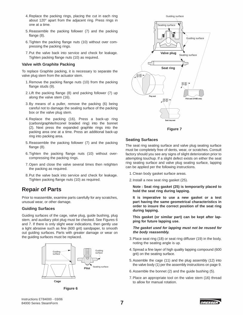
Seating SurfacesThe seat ring seating surface and valve plug seating surfacemust be completely free of dents, wear, or scratches. Consultfactory should you see any signs of slight deterioration prior toattempting touchup. If a slight defect exists on either the seatring seating surface and valve plug seating surface, lappingcan be applied per the following instructions.
1.CIean body gasket surface areas.
2. Install a new seat ring gasket (25).
Note : Seat ring gasket (25) is temporarily placed tohold the seat ring during lapping.
It is imperative to use a new gasket or a test part having the same geometrical characteristics inorder to insure the correct position of the seat ringduring lapping.
This gasket (or similar part) can be kept after lap-ping for future lapping use.
The gasket used for lapping must not be reused forthe body reassembly.
3.Place seat ring (18) or seat ring diffuser (19) in the body,noting the seating angle is up.
4.Spread a fine layer of high quality lapping compound (600grit) on the seating surface.
5. Assemble the cage (11) and the plug assembly (12) intothe valve body (1) per the assembly instructions on page 9.
6.Assemble the bonnet (2) and the guide bushing (5).
7.Place an appropriate tool on the valve stem (16) threadto allow for manual rotation.
Instructions ET84000 - 03/0684000 Series SteamForm 7
Seating surface
Guiding surface
Guiding surface
Seating surfaceValve plug
Seat ring
Figure 7
DV-157-SteamForm-v4 2/20/06 3:54 PM Page 7
8
8.Lap by slightly rotating the valve plug in alternate directions.After several rotations, lift the valve stem, turn it 90 degrees,and repeat the operation.
9.Lapping can be repeated, but should be limited as muchas possible so that the seat remains sufficiently narrowto guarantee tightness.
10. After lapping, disassemble the parts to clean them andthen reassemble, making sure the seating angles arewithin tolerance. See Figure 7.
Note : For more details on the lapping procedureand seating angles, please consult the factory andprovide the valve serial number (found on the serialplate on the actuator).
Gaskets
Gasket seating surfaces must be free of dents, scratches,and corrosion. Clean mating surfaces as required andreplace any non-conforming parts. Spiral-wound gaskets (24, 25, 26, 32, 33) must always be replaced after disassembly.
Seal Rings
Seal rings (27), back-up rings (28), retaining ring (15), and conical springs (23) can be reused if they are free of scratches,erosion, corrosion, or other damage.
Valve Plug
If the valve plug needs to be repaired see instructions forValve Reassemble.
Conical Springs
For Models 84XX2, 84XX3, 84XX6, 84XX7, and 84XX8, alwaysinspect the body bore surface adjacent to where the conicalspring (23) is seated. If this surface has been deformed or ifthere is a groove where the seal seats, the surface should becleaned and honed prior to reassembling the valve.
If the refinishing procedure is unsuccessful, the factory shouldbe consulted for further instructions.
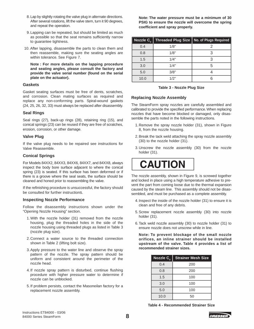
Inspecting Nozzle Performance
Follow the disassembly instructions shown under the“Opening Nozzle Housing” section.
1.With the nozzle holder (31) removed from the nozzlehousing, plug the threaded holes in the side of the nozzle housing using threaded plugs as listed in Table 3(nozzle plug size).
2.Connect a water source to the threaded connectionshown in Table 2 (lifting bolt size).
3.Apply pressure to the water line and observe the spraypattern of the nozzle. The spray pattern should be uniform and consistent around the perimeter of the nozzle head.
4. If nozzle spray pattern is disturbed, continue flushingprocedure with higher pressure water to determine ifnozzle can be unblocked.
5. If problem persists, contact the Masoneilan factory for areplacement nozzle assembly.
Note: The water pressure must be a minimum of 30PSIG to ensure the nozzle will overcome the springcoefficient and spray properly.
Table 3 - Nozzle Plug Size
Replacing Nozzle Assembly
The SteamForm spray nozzles are carefully assembled andcalibrated to provide the specified performance.When replacingnozzles that have become blocked or damaged, only disas-semble the parts noted in the following instructions.
1.Remove the spray nozzle holder (31), shown in Figure 8, from the nozzle housing.
2.Break the tack weld attaching the spray nozzle assembly(30) to the nozzle holder (31).
3.Unscrew the nozzle assembly (30) from the nozzle holder (31).
The nozzle assembly, shown in Figure 9, is screwed togetherand locked in place using a high temperature adhesive to pre-vent the part from coming loose due to the thermal expansioncaused by the steam line. This assembly should not be disas-sembled, and must be purchased as a complete assembly.
4. Inspect the inside of the nozzle holder (31) to ensure it isclean and free of any debris.
5.Screw replacement nozzle assembly (30) into nozzleholder (31).
6.Tack weld nozzle assembly (30) to nozzle holder (31) toensure nozzle does not unscrew while in line.
Note: To prevent blockage of the small nozzle orifices, an inline strainer should be installedupstream of the valve. Table 4 provides a list of recommended strainer sizes.
Table 4 - Recommended Strainer Size
Nozzle CV
Strainer Mesh Size
0.4 200
0.8 200
1.5 100
3.0 100
5.0 100
10.0 50
Instructions ET84000 - 03/0684000 Series SteamForm
Nozzle CV
Threaded Plug Size No. of Plugs Required
0.4 1/8" 2
0.8 1/8" 3
1.5 1/4" 3
3.0 1/4" 5
5.0 3/8" 4
10.0 1/2" 6
DV-157-SteamForm-v4 2/20/06 3:54 PM Page 8

Instructions ET84000 - 03/0684000 Series SteamForm 9
Failure to install the appropriate strainer can result in blockageof nozzle. This can impact heat sensitive systems.
Figure 8 - Spray Nozzle Holder
Figure 9 - Spray Nozzle Assembly
Valve ReassemblePinning the Valve Plug
The valve plug assembly consists of a stem (16) that is threaded into the valve plug (12). Threading the stem into the plug should use tools similar to those shown in Figure 4,under valve disassembly. To secure this assembly, the stem(16) is then pinned (17) and tack welded to the valve plug (12).
If the valve plug (12) or stem (16) needs to be replaced, anentire assembly should be purchased from the factory toensure product strength and integrity. Re-machining of theseparts in the field can seriously impair the mechanical strengthand integrity of the valve plug stem assembly.
Seal Ring Assembly
Model 844XX (Auxiliary Pilot Plug) and 845XX(Metal Seal Ring)
1.To insert the spring-energized seal ring in the valve pluggroove, place it over the conical top of the plug, thenpush down evenly from all sides until the ring slips intothe groove. See Figure 10.
Note: These valves may also be equipped with asecondary metal seal and elastomeric back-up ringlocated on the lower area of the plug near the seat-ing surface.
2. Install the back-up ring (28) onto the plug using care notto damage the ring on any sharp surfaces. The back-upring does not require lubrication, however, a light coatingof compatible lubricant will help install the seal.
3. Install the seal ring (27) over the back-up ring (28).
Note: When the plug assembly is installed into the cage bore, the lead in angle of the cage willcompress the ring into place. If the seal ring is notcompressed a ring compression tool may berequired for proper installation.
Figure 10 - Installing Seal Ring
Model 843XX (TEC Seal)
These valves are equipped with an inner elastomeric ring andan outer PTFE ring.
1. Insert the elastomeric back-up ring (28) into the groove.
2.Place the PTFE seal ring (27) in boiling water for a few minutes. Slide the seal ring along the plug until it slips intothe groove.
3.For optimum insertion of the ring, a Serflex type ring com-pressor can be used to compress the ring in the groovefor several minutes.
Model 849XX (Graphite Seal Ring)
These valves are also equipped with an inner and outer ringarrangement. The inner metal ring has a straight cut and theouter ring is made of graphite.
1.Replacement graphite seal rings (27) are supplied in a closed ring form, and a notch must be cut before beingassembled to the plug.
Graphite seal rings are fragile so the following operations mustbe carried out very carefully.
DV-157-SteamForm-v4 2/20/06 3:54 PM Page 9

Instructions ET84000 - 03/0684000 Series SteamForm 10
2.Using a sharp blade, make a notch in the graphite ring.Hold the ring on either side of the notch between thethumb and index and bend until it breaks.
3.Using a very fine file, adjust each end of the ring so thatits external circumference corresponds to the internal circumference of the inside diameter of the cage (11).
4.To adjust the length of the ring correctly, insert the newgraphite ring into the cage with the ring against the innerwall of the cage (allowing for minimum play between thetwo ends of the ring).
5.First assemble the inner metal ring into the cage groove,then assemble the graphite ring over the metal ring. Becareful not to damage the parts.
Note: The cuts on each ring should be placed approximately 180° apart.
Completing Valve Body Assembly
Proceeds as follows:
Note: Some valve designs may utilize a welded seatring. Disregard steps (1) and (2) for these designsand proceed to step (3).
1.After checking all sealing surfaces to ensure they arethoroughly clean, assemble the seat ring gasket (25) inthe valve body (1). Make sure the gasket is centeredproperly in the body.
2.Assemble the seat ring (18) or seat ring diffuser (19) intothe valve body on top of the seat ring gasket (25). Formodels 84XX0, 84XX1, 84XX4, and 84XX5 it may benecessary to secure the seat ring inside the valve bodythrough either bolting or threading. The proper methodcan be determined by visual inspection or by contactingthe factory.
A.For valves using the bolted seat ring design, the seatnuts (22) should be tightened according to thesequence shown in Figure 11. For the appropriate bolttorque values, please consult the factory.
B.For valves using a threaded seat ring design, pleaseconsult factory for assistance. Masoneilan has specialtools available for applying hydraulic torque to the seatring. These tools are available upon request.
For 844XX ( Auxiliary Pilot Plug ) proceed to step 5.3.For valves using a straight plug design (See Figure 3),
install the cage into the valve body per steps A and B.For valves using a bell shaped design (See Figure 2),proceed to step 6.
A.For models 84XX2, 84XX3, 84XX6, 84XX7, and84XX8 (valves utilizing a clamped cage design), installthe cage (11) by seating it on top of the seat ring.
B.For models 84XX0, 84XX1, 84XX4, and 84XX5(valves utilizing a hung cage design), inspect the gas-ket surface between the valve body and cage toensure it is clean from debris and free from scratchesor damage. Next, install the cage gasket (26) followedby the cage (11) into the valve body (1).
4. Insert the valve plug, stem assembly (12) including theseal rings (27) and back-up rings (28) if applicable, intothe valve cage (11) taking particular care not to damagethe seal rings (27, 28) upon entry. Proceed to step 7.
Valve Plug and Cage Assembly
Valve Plug and Auxiliary Pilot Plug Assembly
5.Assemble either the flat spring washers (sizes 3" + 4") orthe coil springs (sizes 6" to 16"), then assemble the valveplug assembly (12), using the same tools as those usedfor disassembly (see section on disassembly). Compressthe springs so that the retaining ring (15) can be installedinto the groove in the main plug.
6.Assemble the cage (11) over the valve plug assembly (12)from the top of the plug stem. Make sure the seal ring (27)in the plug groove stays positioned correctly. Insert thecage (11) and plug assembly (12) into the valve body (1).
7.For models 84XX2, 84XX3, 84XX6, 84XX7, and 84XX8(valves utilizing a clamped cage design), install the conical spring (23) on top of the cage (11).
8. Install the body gasket (24) inside the groove on top of the valve body (1) and make sure it is centered with the valve.
Bonnet Assembly
Bonnet Assembly
1.Make sure the packing (6) and guide bushing (5) havebeen removed from the bonnet (2).
2.Position the bonnet (2) above the valve body (1), so thatthe packing flange studs (9) are perpendicular to theinlet of the valve.
3.Assemble the bonnet (2) over the valve stem (16) andpush it down. Use caution during this step so as not todamage the stem.
4.Grease the threads of the valve body studs (3) and thebearing surfaces of the body stud nuts (4).
5.Assemble the body stud nuts (4) by hand. Hand tightenthe nuts evenly so that the internal parts are held inplace. The face of the bonnet should be parallel to theupper face of the body.
6.Slide the guide bushing (5) onto the valve plug stem (16)and let it drop to the bottom of the packing box.
Tightening Body Nuts
In order to achieve perfect alignment of the body and theinternal components, it may be beneficial to provide loadingto the plug stem assembly (12) during tightening. This maybenefit the positioning of various parts in installations wherethe actuator and trim are installed horizontally.
The force can be applied with the actuator as follows:
Place the actuator on the valve bonnet (2) by means of the yoke nut (29) and connect the valve plug stem (16) to the actuator stem.
DV-157-SteamForm-v4 2/20/06 3:54 PM Page 10

Instructions ET84000 - 03/0684000 Series SteamForm 11
During this operation, make sure the plug does not turn whenit is seated. If the plug travel is very small and there is a largeamount of plug stem inside the actuator, it may be necessaryto remove the yoke nut and lift the actuator so that the plug isnot touching the seat.
Refer to the appropriate instruction manual for the actuatorand each unique accessory.
Tighten the body nuts (4) evenly by applying the torque indi-cated in Table 5. Use the tightening sequence as indicated inFigure 11.
Packing Box Assembly
Assemble the packing box components per the maintenanceinstructions in the Packing Box maintenance procedure onPage 6.
Bolt Torque SequenceFigure 11 details the tightening sequence for the bonnet/bodybolts torques for a 84000 Series SteamForm®. Evenly applytorque to the body nuts (4) to the amount specified in Table 5.
Table 5 - Body/Bonnet Bolting Torque
1802207601100230350
12001850440320
18501850710650
18502400115011501850220012501150125022001150125015002600
3
4
6
8
10
12
16
150/300600900
1500150/300
600900
1500150/300
600900
1500150/300
600900
1500150/300
600900
1500150/300
600900
1500150/300
600900
1500
3/4 103/4 101 1/4 81 1/4 87/8 97/8 9
1 1/2 81 1/2 8
1 81 8
1 3/4 81 3/4 81 1/4 81 1/4 81 3/4 81 3/4 81 1/2 81 1/2 81 3/4 81 3/4 81 1/2 81 1/2 81 1/2 81 3/4 81 1/2 81 1/2 81 1/2 81 3/4 8
886688668
12888
12888
1212128
12161612162020
133163563815170259889
1370326237
13701370526481
13701778852852
13701630926852926
163085282611111926
VAL orque
N.m
TORQUEBody/Bonnet Bolting Requirements
VE SIZE Body Nuts Assembly T
Nominalsize(in)
Pressurerating
Size(in) Quantity ft.lb
Figure 11 - Bolt Torque Sequence
Nozzle AssemblyDesuperheating performance is reliant upon water injectionof the SteamForm® spray nozzles. The nozzle must maintainan aerosol spray effect, and a hollow cone spray pattern.Weld slag, rust, and other debris in the water lines can disturb the nozzle spray pattern and can result in poor waterinjection and temperature control. Periodic inspection of the spray nozzle’s water pattern should be conducted to ensure nozzle performance. Refer to the instructions under“Inspecting Nozzle Performance” for the detailed test procedure.
To assemble the nozzles into the valve:
1.After inspecting the surfaces of the nozzle housing forany damage or debris, install the nozzle gasket (32) intothe bottom of the nozzle housing.
2.Securely install the nozzle holder (31) into the nozzle housing. The nozzle holder (31) should fit flush with the housing surface, otherwise remove the nozzle holder (31) and confirm the nozzle (30) is clean from debris.
3. Install the nozzle flange gasket (33) into the groove on the nozzle housing.
4.Place the nozzle housing flange (34) over the nozzleflange studs (35). Securely tighten the nozzle flange nuts (36) to the factory suggested torque.
The nozzle assembly is screwed and locked in placeusing a high temperature adhesive to prevent part fromcoming loose due to thermal expansion caused by thesteam line. This assembly should not be disassembled,and must be purchased as a complete assembly.
DV-157-SteamForm-v4 2/20/06 3:54 PM Page 11

Instructions ET84000 - 3/0684000 Series SteamForm 12
Item No. Description
1 Body
2 Bonnet
3 Body Stud
4 Body Nut
5 Guide Bushing
6 Packing S/A
7 Packing Follower
8 Packing Flange
9 Packing Flange Stud
10 Packing Flange Nut
11 Cage
12 Plug
13 Pilot Spring
14 Auxiliary Pilot Plug
15 Retaining Ring
16 Stem
17 Grooved Pin
18 Seat Ring
19 Seat Ring Diffuser
20 Diffuser
21 Seat Stud
22 Seat Nut
23 Conical Spring
24 Body Gasket
25 Seat Ring Gasket
26 Cage Gasket
27 Seal Ring
28 Back-Up Ring
29 Yoke Nut
30 Nozzle S/A
31 Nozzle Holder
32 Nozzle Gasket
33 Nozzle Flange Gasket
34 Nozzle Housing Flange
35 Nozzle Flange Stud
36 Nozzle Flange Nut
•
•
•
Parts may differ according to specific valve supplied.
• Recommended Spare Parts (some parts may not be applicableto all designs)
•
•
•
Parts Reference For 84000
DV-157-SteamForm-v4 2/20/06 3:54 PM Page 12

Instructions ET84000 - 03/0684000 Series SteamForm 13
SteamForm Model 84XX3Lo-dB Plug with Diffuser. Shown withoptional Auxiliary Pilot Plug design.
SteamForm Model 84XX7Lo-dB Cage with Diffuser. Shownwith Balanced Plug design.
Figure 12
Figure 13
DV-157-SteamForm-v4 2/20/06 3:54 PM Page 13

Instructions ET84000 - 3/0584000 Series SteamForm 14
SteamForm Model 84XX7GGlobe style design. Lo-dB cage withdiffuser. Shown with optional AuxiliaryPilot Plug design.
Figure 14
DV-157-SteamForm-v4 2/20/06 3:54 PM Page 14

Instructions ET84000 - 03/0684000 Series SteamForm 15
ActuationType 87/88 Multi-Spring Diaphragm Actuators
Connecting Type 87 (Air to Extend) No. 6 Actuator(Figure 15)
1.Tightly assemble the hex nuts (1) onto the plug stem.
2.Push down the actuator, and screw on the yoke nut (33)at the same time. Then assemble the bottom stem connector (2). As soon as it becomes possible, insert thevalve stem into the actuator stem (10). The stem must be inserted far enough so that when there is no air in theactuator, the valve plug does not touch the seat.
3.Tighten the yoke nut (33).
4.Supply air to the actuator at the final pressure.
5.Use the pointer (7) to set the travel scale (9) to the valveopen position.
6.Supply the actuator with air at a sufficiently high pressureto obtain a travel equal to the nominal travel of the valve.
7.Unscrew the plug stem until the valve plug is in contactwith the seat. Do not turn the valve plug on the seat asthis could damage the sealing surfaces.
8.Screw the hex nuts (1) as far as they will go and checkthat operation is correct.
Connecting Type 88 (Air to Retract) No. 6 Actuator(Figure 15)
1.Tightly assemble the hex nuts (1) onto the plug stem.
2.Push down the actuator, and screw on the yoke nut (33)at the same time. Then assemble the bottom stem connector (2). As soon as it becomes possible, insert thevalve stem into the actuator stem (10). The stem must beinserted far enough so that when there is no air in theactuator, the valve plug does not touch the seat.
3.Tighten the yoke nut (33).
4.Unscrew the valve plug stem until the valve plug comesinto contact with the seat. Do not turn the valve plug onthe seat as this could damage the sealing surfaces.
5.Supply air to the actuator until the stem has travelled atleast .40 inches (10 mm).
6.Unscrew the plug stem by the number of turns N1 specified in Table 6.
Note: For model 844XX valves, use the N2 values inTable 6 to ensure seating tightness of the pilot plug.
Table 6 - Type 88, Air to Retract - valve seating
7.Screw the hex nuts (1) as far as they will go and checkthat operation is correct.
8.Use the pointer (7) to set the travel scale (9) to the valveclosed position.
Connecting Type 87 (Air to Extend) No. 10, 16 and23 Actuators (Figure 15)
1.Tightly assemble hex nut (1) onto the plug stem.
2.Screw the top stem connector (4) assembly tightly ontothe actuator stem (10).
3.Push down the actuator, and screw on the yoke nut (33)at the same time. Then assemble the bottom stem connector (2) assembly by screwing until it comes intocontact with the hex nut (1).
4.Push down the actuator and tighten the yoke nut (33).
5.Supply the actuator with air at the initial pressure indicated on the spring scale.
6.Position the stem connector assembly at distance “X”indicated in Table 7.
7.Use the pointer (7) to set the travel scale (9) to the valveopen position.
8.Supply the actuator with air at a high enough pressure toobtain a travel equal to the nominal travel of the valve.
Note: For model 844XX valves, reduce the travel byValue A indicated in Table 8.
9.With the plug correctly positioned on the seat, unscrewthe bottom stem connector (2) assembly until it comesinto contact with the top stem connector (4). Tighten thesocket head cap screws (5), hex nut (1) and lock nut (32)and check that the operation is correct.
Connecting Type 88 (Air to Retract) No. 10, 16 and23 Actuator (Figure 15)
1.Supply the actuator with air to retract stem.
2.Unscrew the top stem connector (4) in accordance withdimension “X” in Table 7.
3.Tightly assemble hex nut (1) onto the plug stem.
4.Tightly screw the top stem connector (4) assembly ontothe actuator stem (10).
5.Push down the actuator, and screw on the yoke nut (33)at the same time. Then assemble the bottom stem connector (2) assembly by screwing until it comes intocontact with the hex nut (1).
6.Push down the actuator and tighten the yoke nut (33).
7.With the plug correctly positioned on the seat, unscrewthe bottom stem connector (2) assembly to bring it into contact with the top stem connector (4).
8.Supply air to the actuator until the stem has travelled atleast 0.40 inches (10 mm).
9.Unscrew the top stem connector (4) by the number of turnsN1 specified in Table 6 then lock manually with hex nut (1).
Note: For model 844XX valves, use N2 values inTable 6 to ensure seating tightness of the pilot plug.
1"
3/4"
5/8"
1/2"
1.25
1.25
1.5
1.5
4.75
4.25
3.5
3
Plug Stem N1(turn)
N2844XX(turn)
mmDiameter in
0.09
0.08
0.08
0.075
2.3
2.0
2.0
1.9
DV-157-SteamForm-v4 2/20/06 3:54 PM Page 15

Instructions ET84000 - 03/0684000 Series SteamForm 16
10. Release the pressure in the actuator. Use pointer (7) to set the travel scale (9) to the actuator supply pressure sothat the two stem connectors come into contact. Thentighten the socket head cap screws (5), hex nut (1), andlock nut (32).
11. Shut off the closed valve pressure and check that operation is correct.
Table 7 - Position of Top Stem Connector
Table 8 - Auxiliary Pilot Plug Travel
Parts Reference For Spring DiaphragmActuators - Type 87/88 Multispring
• Not provided for Size 6 Actuator
Item No. Description
1 Hex Nut
2 Stem Connector, Bottom
3 Cap Screw, Hex Head
4 Stem Connector, Top
5 Cap Screw, Socket Head
6 Connector Insert
7 Pointer
8 Screw, Pan Head
9 Scale, Travel
10 Actuator Stem
31 Yoke, Machining
32 Lock Nut
33 Yoke Nut
•
•
•
•
ActuatorSize
Travel “X”Actuator 87 “X”Actuator 88
in mm in mm in mm
10 0.8 20 5.12 130.04.62 117.3
10 1.5 38 5.44 138.2
16 0.8 20 8.00 203.2
7.02 178.3
16 1.5 38 8.50 228.6
16 2.0 51 9.28 235.7
16 2.5 63.5 9.50 241.3
23 0.8 20 8.25 209.5
23 1.5 38 8.62 218.9
23 2.0 51 9.12 231.6
23 2.5 63.5 9.59 243.6
Value A
mm
2
2
3 & 4
6
8
10, 12 & 16
150, 300 or 600
900 or 1500
150, 300 or 600
900 or 1500
Pressure RatingValve Size(inches) in
0.1
0.08
0.12
0.2
0.24
0.275
2.5
2
3
5
6
7
DV-157-SteamForm-v4 2/20/06 3:54 PM Page 16

Instructions ET84000 - 03/0684000 Series SteamForm 17
Type 87 Air to CloseNo. 6
Type 88 Air to OpenNo. 6
Model 88 ActuatorAir to Retract (Open)
Model 87 ActuatorAir to Extend (Close)
Type 87 Air to CloseNo. 10-16-23
Type 88 Air to OpenNo. 10-16-23
Figure 15
DV-157-SteamForm-v4 2/20/06 3:54 PM Page 17

Instructions ET84000 - 03/0684000 Series SteamForm 18
Type 51/52/53 Cylinder ActuatorsConnecting Double Acting (Model 51) (Figures 18& 19)
1. Install actuator on the valve body with drive nut.
2.Connect manual loading panel tubing to the Top Plate (17).
3.Apply required air pressure through the manual loadingpanel to completely extend the actuator stem.
4.Reconnect manual loading panel tubing from the TopPlate (17) to the Yoke (1), which is integrated into thebottom plate connection.
5.Retract the actuator stem either pneumatically or with a handwheel approximately .1" (2mm) using the visualstroke scale as shown in Figure 16.
Figure 16
6.Assemble the Split Clamp (22).
Note: If the split clamp does not engage with bothstems, then retract the actuator stem until align-ment and engagement is achieved.
Make sure the valve is fully extended.
Figure 17
7.Assemble and tighten Indicator Arm (23), Spring LockWashers (25), and Hexagon Bolts (24).
8.Line up the indicator plate (26), with Indicator arm (23)and check actuator for proper operation.
Connecting Air to Extend (Model 52) (Figure 20)
1. Install actuator on the valve body with drive nut.
2.Connect manual loading panel tubing to the top plate (17).
3.Apply required air pressure through the manual loadingpanel to completely extend the actuator stem.
4.Extend the actuator stem either pneumatically or with ahandwheel approximately .1" (2mm) using the visualstroke scale as shown in Figure 16.
5.Assemble the Split Clamp (22).
Note: If the split clamp does not engage with bothstems, then extend the actuator stem until align-ment and engagement is achieved.
Make sure the valve is fully extended.
6.Assemble and tighten Indicator Arm (23), Spring LockWashers (25), and Hexagon Bolts (24).
7.Line up the indicator plate (26), with Indicator arm (23)and check actuator for proper operation.
Connecting Air to Retract (Model 53) (Figure 21)
1. Install actuator on the valve body with drive nut.
2.Connect manual loading panel tubing to the yoke (1),which is integrated into the bottom plate connection.
3.Retract the actuator stem either pneumatically or with ahandwheel approximately .1" (2mm) using the visualstroke scale as shown in Figure 16.
4.Assemble the Split Clamp (22).
Note: If the split clamp does not engage with bothstems, retract the actuator stem until alignmentand engagement is achieved.
Make sure the valve is fully retracted.
5.Assemble and tighten Indicator Arm (23), Spring LockWashers (25), and Hexagon Bolts (24).
6.Line up the indicator plate (26), with Indicator arm (23)and check actuator for proper operation.
DV-157-SteamForm-v4 2/20/06 3:54 PM Page 18

Instructions ET84000 - 03/0684000 Series SteamForm 19
Model 51 Double ActingWith handwheel without volume chamber
Model 51 Double ActingWith handwheel with volume chamber
Figure 18
DV-157-SteamForm-v4 2/20/06 3:54 PM Page 19

Instructions ET84000 - 03/0684000 Series SteamForm 20
Model 51 Double ActingWithout handwheel without volume chamber
Model 51 Double ActingWithout handwheel with volume chamber
Figure 19
DV-157-SteamForm-v4 2/20/06 3:54 PM Page 20

Instructions ET84000 - 03/0684000 Series SteamForm 21
Model 52 Air to extend with handwheel
Model 52 Air to retract without handwheel
Figure 20
DV-157-SteamForm-v4 2/20/06 3:54 PM Page 21

Instructions ET84000 - 03/0684000 Series SteamForm 22
Model 53 Air to extend with handwheel
Model 53 Air to retract without handwheel
Figure 21
DV-157-SteamForm-v4 2/20/06 3:54 PM Page 22

Instructions ET84000 - 03/0684000 Series SteamForm 23
CM, DM handwheelTypical for Models 51/52/53
Figure 22
DV-157-SteamForm-v4 2/20/06 3:54 PM Page 23

Instructions ET84000 - 03/0684000 Series SteamForm 24
Ref No. Description Ref No. Description Ref No. Description
1 Yoke 24 Hexagon bolt 47 Locking pin case
2 Piston rod S/A 25 Spring lock washer 48 Pin
3 Lower spring button 26 Indicator plate 49 Spring
4 Spring 27 Cross recessedhead screw 50 Hexagon socket
set screw
5 Hexagon sockethead cap screw 28 Exhaust pipe 51 Guide key
6 Spring lock washer 29 Spring lock washer 52 Worm gear
7 Spring tube 30 Plug 53 Spacer tube
• 8 Guide bushing • 31 Piston S/A 54 Adapter
9 Compression bolt • 32 Guide bushing 55 Set screw
10 Upper spring button • 33 O ring (Piston rod) 56 Worm
11 Thrust bearing • 34 Rod scraper • 57 Bearing
12 Compression nut 35 Hexagon bolt 58 Retaining ring
13 Separator plateModel 52/53 36 Spring lock washer 59 Hand wheel shaft
14 Cylinder tube 37 Gear box 60 Key (Worm)
15 Cylinder tube 38 Gear box cover S/A 61 Key (Handwheel)
• 16 Guide ring • 39 O ring 62 Retaining ring
17 Top plate • 40 Thrust bearing 63 Handwheel
18 Set screw 41 Adjustment screw 64 Grip
19 Center bolt 42 Locking nut 65 Directional plate
20 Hexagon nut 43 Adjustment nut 66 Self locking nut
• 21 O ring (Piston, Top plate) 44 Piston rod
engagement 67 Operating informa-tion plate
22 Split clamp • 45 Bearing 68 Drive screw
23 Indicator arm 46 Retaining pin 69 Separator plate(Model 51)
70 Volume chambertube
Parts Reference Table 51/52/53 Actuators
• Recommended Spare Parts
DV-157-SteamForm-v4 2/20/06 3:54 PM Page 24

Instructions ET84000 - 3/0684000 Series SteamForm 25
Notes
DV-157-SteamForm-v4 2/20/06 3:54 PM Page 25

Dresser Valve India Pvt. Ltd.205, Mohta Building4 Bhikaiji Cama PlaceNew Delhi, 110 066, IndiaPhone: +91-11-6164175Fax: +91-11-6165618
ITALYDresser Italia S.r.l.Masoneilan OperationsVia Cassano, 7780020 Casavatore, Napoli Italy Phone: +39-081-7892-111Fax: +39-081-7892-208
JAPANNiigata Masoneilan Co. Ltd.(NIMCO)20th Floor, Marive East TowerWBG 2-6 Nakase, Mihama-ku, Chiba-shi, Chiba 261-7120 JapanPhone: +81-43-297-9222Fax: +81-43-299-1115
KOREADresser Korea Inc.2109 Kuk Dong Building 60-13-Ka, Choongmu-ro Chung-KuSeoul, KoreaPhone: +82-2-2274-0748Fax: +82-2-2274-0720
KUWAITDresser Flow SolutionsMiddle East Operations10th Floor, Al Rashed Complex Fahad Salem Street, P.O. Box 242Safat, 13003, KuwaitPhone: +965-9061157Fax: +965-3987879
MALAYSIADresser Flow SolutionsBusiness Suite, 19A-9-1, Level 9UOA Centre, No. 19, Jalan Pinang50450 Kuala Lumpur, West MalaysiaPhone: +60-3-2161-0322Fax: +60-3-2163-3612
MEXICODresser Valve de Mexico, S.A. de C.V.Henry Ford No. 114, Esq. FultonFraccionamiento Industrial San Nicolas54030 Tlalnepantla Estado de MexicoPhone: 52-5-310-9863Fax: 52-5-310-5584
THE NETHERLANDSDresser Valves EuropeSteenhouwerstraat 113194 AG Hoogvliet, The NetherlandsPhone: +31-10-438-4122Fax: +31-10-438-4443
NIGERIADresser Flow SolutionsPlot 293, Akin Olugbade StreetVictoria Island, Lagos, NigeriaPhone: +234-1-555-4229Fax: +234-1-555-7969
BELGIUMDresser Valves EuropeBoulevard du Souverain 207 B2 Vorstlaan, B-1160 Brussels, BelgiumPhone: +32-2-344-0970Fax: +32-2-344-1123
BRAZILDresser Industria e Comercio LtdaDivisao MasoneilanRua Funchal, 129 - Conj. 5A04551-060 - Sao Paulo - SP BrazilPhone: 55-11-2146-3600Fax: 55-11-2146-3610
CANADAOntarioDresser - MasoneilanDI Canada, Inc.835 Harrington Court, 2nd FloorBurlington, Ontario L7N 3P3,CanadaPhone: 905-335-3529Fax: 905-336-7628
CHINADresser Flow Solutions, Beijing Rep. OfficeSuite 1703, Capital Mansion6 Xinyuannan Rd. Chaoyang District Beijing 100004, ChinaPhone: +86-10-8486-4515Fax: +86-10-8486-5305
FRANCEMasoneilan - Dresser ProduitsIndustriels Energy 5130/190 Boulevard de Verdun92413 Courbevolie cedex, FrancePhone: +33-1-4904-9000Fax: +33-1-4904-9010
Dresser Produits Industriels S.A.S.,Masoneilan Customer ServiceCentre55 rue de la Mouche, Zone Industrielle69540 Irigny, FrancePhone: +33-4-72-39-06-29Fax: +33-4-72-39-21-93
GERMANYDresser Valves Europe GmbHHeiligenstrasse 75Viersen D-41751, GermanyPhone: +49-2162-8170-0Fax: +49-2162-8170-280
Dresser Valves Europe GmbHUhlandstrasse 5860314 Frankfurt, GermanyPhone: +49-69-439350Fax: +49-69-4970802
INDIADresser Valve India Pvt. Ltd.305/306, "Midas", Sahar PlazaMathurdas Vasanji RoadJ.B. Nagar, Andheri EastMumbai, 400059, IndiaPhone: +91-22- 8381134Fax: +91-22-8354791
Instructions ET84000 - 03/0684000 Series SteamFormCopyright 2006 Dresser, Inc. All rights reserved.
RUSSIADS ControlsNekhinskaya Street, 61Veliky NovgorodRussia, 173021Phone: +7-8162-15-7898Fax: +7-8162-15-7921
SAUDI ARABIADresser AL Rushaid Valve & Instrument Co., Ltd.(Darvico)P.O. Box 10145Jubail Industrial City 31961, Saudi ArabiaPhone: +966-3-341-0278Fax: +966-3-341-7624
SINGAPOREDresser Singapore Pte Ltd.16 Tuas Avenue 8Singapore 639231Phone: +65-6-6861-6100Fax: +65-6-6861-7172
SOUTH AFRICADresser LimitedP.O. Box 223416 Edendale RoadEastleigh, Edenvale 1610Republic of South AfricaPhone: +27-11-452-1550Fax: +27-11-452-6542
SPAINMasoneilan S.A.C/Murcia 39 C08830 Sant Boi de LlobregatBarcelona, SpainPhone: +34-93-652-6430Fax: +34-93-652-6444
UNITED ARAB EMIRATESDresser Flow Soluions Middle East OperationsP.O. Box 61302Roundabout 8Units JA01 & JA02Jebel Ali Free ZoneDubai, U. A. E.Phone: +971-4-8838-752Fax: +971-4-8838-038
UNITED KINGDOMDI U.K. Ltd.East GillibrandsSkelmersdale, Lancashire WN8 9TU, EnglandPhone: +44-1695-52600Fax: +44-1695-52601
DI U.K. Ltd.Unit 4, Suite 1.1, Nobel HouseGrand Union Office ParkPacket Boat LaneUxbridge, Middlesex UB8 2GHPhone: +44-1895-454-900Fax: +44-1895-454-919
UNITED STATESDresser - Masoneilan85 Bodwell StreetAvon, MA 02322-1190Phone: 508-586-4600Fax: 508-427-8971
Dresser - Masoneilan4841 Leopard StreetCorpus Christi, TX 78408-2621Phone: 361-877-2414Fax: 361-584-1196
Dresser - MasoneilanDresser Direct1250 Hall CourtDeer Park, TX 77536Phone: 281-884-1000Fax: 281-884-1010
Dresser - Masoneilan16250 Port Northwest DriveHouston, TX 77041Phone: 832-590-2300Fax: 832-590-2529
Dresser - Masoneilan2950 East Birch StreetBrea, CA 92821Phone: 714-572-1528Fax: 714-572-1463
Sales Office Locations
DV-157-SteamForm-v4 2/20/06 3:53 PM Page a