d:vita機種資料tss-1100tss-1200.dwg model (1)diagramas.diagramasde.com/audio/tss-1200 infinity...
TRANSCRIPT

TSS-Sub1200
(TSS-1200 SYSTEM)
SERVICE MANUAL
Infinity Systems Incorporated 250 Crossways Park Dr.
Woodbury, New York 11797 Rev0 12/2006
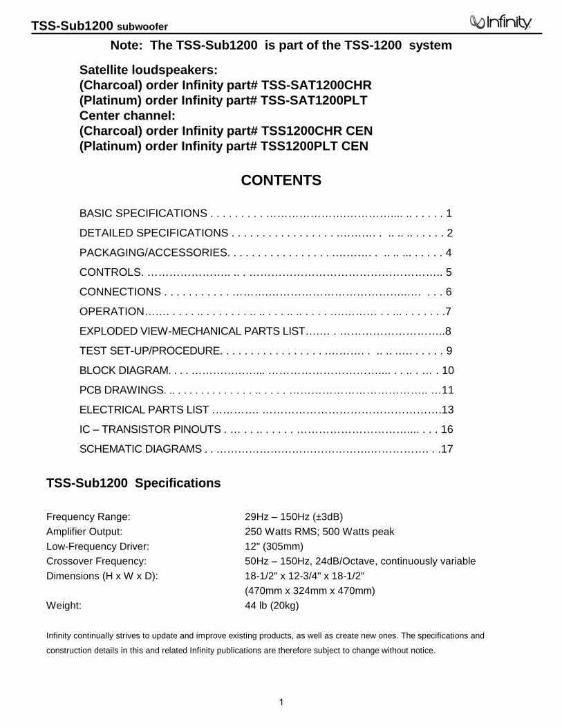
Note: The TSS-Sub1200 is part of the TSS-1200 system
Satellite loudspeakers: (Charcoal) order Infinity part# TSS-SAT1200CHR (Platinum) order Infinity part# TSS-SAT1200PLT Center channel: (Charcoal) order Infinity part# TSS1200CHR CEN (Platinum) order Infinity part# TSS1200PLT CEN
CONTENTS
BASIC SPECIFICATIONS . . . . . . . . . ………………….………….... .. . . . . . 1
DETAILED SPECIFICATIONS . . . . . . . . . . . . . . . . . .………. . .. .. .. . . . . . 2
PACKAGING/ACCESSORIES. . . . . . . . . . . . . . . . . .………. . .. .. ... . . . . . 4
CONTROLS. ………………….. .. . …………………………………………….. 5
CONNECTIONS . . . . . . . . . . . ……….………………………………..…. . . . 6
OPERATION……. . . . . .. . . . . . . . .. .. . . . .. .. . . . . ….……… . . ... . . . . . . .7
EXPLODED VIEW-MECHANICAL PARTS LIST….… . ………………………..8
TEST SET-UP/PROCEDURE. . . . . . . . . . . . . . . . . .………. . .. .. .…. . . . . . 9
BLOCK DIAGRAM. . . . ………………... ………………………….... . . .. . … . 10
PCB DRAWINGS. .. . . . . . . . . . . . . . .. . . . . ……………………………….. …11
ELECTRICAL PARTS LIST …………. ………………………………………….13
IC – TRANSISTOR PINOUTS . … . . .. . . . . . ………………………….... . . . 16
SCHEMATIC DIAGRAMS . . …………………………………….……………. . .17
TSS-Sub1200 Specifications
Frequency Range: 29Hz – 150Hz (±3dB) Amplifier Output: 250 Watts RMS; 500 Watts peak Low-Frequency Driver: 12" (305mm) Crossover Frequency: 50Hz – 150Hz, 24dB/Octave, continuously variable Dimensions (H x W x D): 18-1/2" x 12-3/4" x 18-1/2"
(470mm x 324mm x 470mm) Weight: 44 lb (20kg)
Infinity continually strives to update and improve existing products, as well as create new ones. The specifications and
construction details in this and related Infinity publications are therefore subject to change without notice.
TSS-Sub1200 subwoofer
1
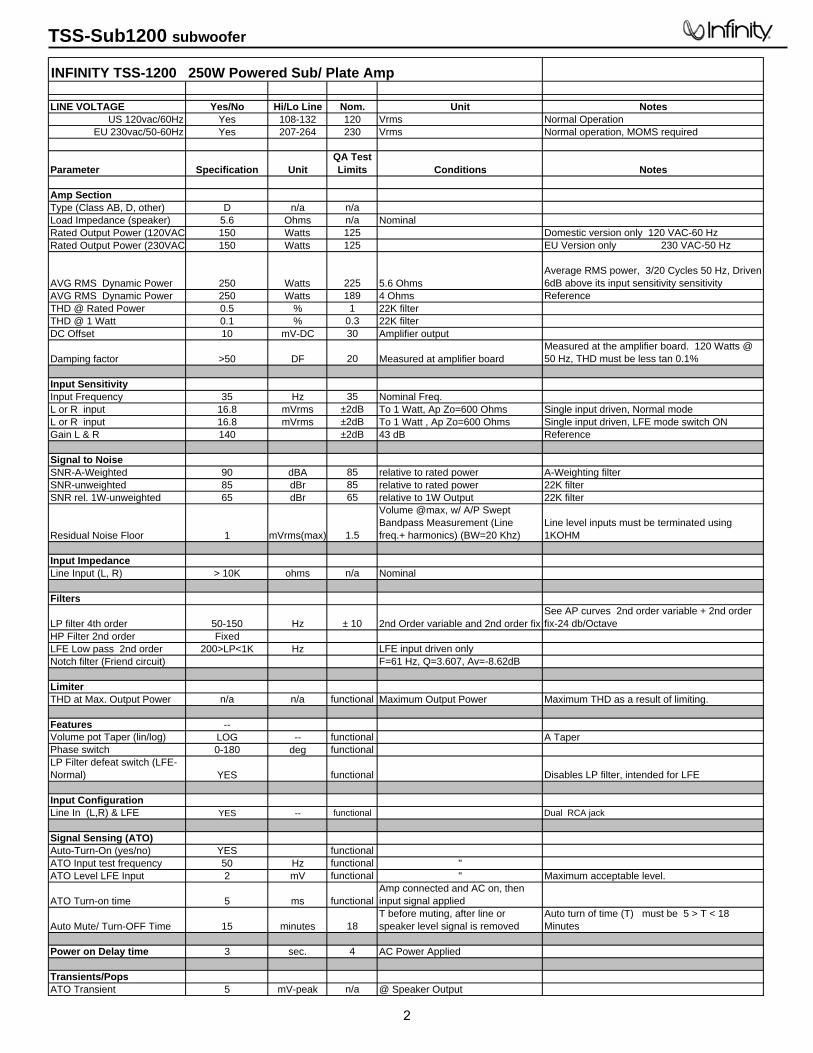
INFINITY TSS-1200 250W Powered Sub/ Plate Amp
LINE VOLTAGE Yes/No Hi/Lo Line Nom. Unit NotesUS 120vac/60Hz Yes 108-132 120 Vrms Normal Operation
EU 230vac/50-60Hz Yes 207-264 230 Vrms Normal operation, MOMS required
Parameter Specification UnitQA Test Limits Conditions Notes
Amp SectionType (Class AB, D, other) D n/a n/aLoad Impedance (speaker) 5.6 Ohms n/a NominalRated Output Power (120VAC 150 Watts 125 Domestic version only 120 VAC-60 HzRated Output Power (230VAC 150 Watts 125 EU Version only 230 VAC-50 Hz
AVG RMS Dynamic Power 250 Watts 225 5.6 Ohms Average RMS power, 3/20 Cycles 50 Hz, Driven 6dB above its input sensitivity sensitivity
AVG RMS Dynamic Power 250 Watts 189 4 Ohms ReferenceTHD @ Rated Power 0.5 % 1 22K filterTHD @ 1 Watt 0.1 % 0.3 22K filterDC Offset 10 mV-DC 30 Amplifier output
Damping factor >50 DF 20 Measured at amplifier board Measured at the amplifier board. 120 Watts @ 50 Hz, THD must be less tan 0.1%
Input SensitivityInput Frequency 35 Hz 35 Nominal Freq.L or R input 16.8 mVrms ±2dB To 1 Watt, Ap Zo=600 Ohms Single input driven, Normal modeL or R input 16.8 mVrms ±2dB To 1 Watt , Ap Zo=600 Ohms Single input driven, LFE mode switch ONGain L & R 140 ±2dB 43 dB Reference
Signal to NoiseSNR-A-Weighted 90 dBA 85 relative to rated power A-Weighting filterSNR-unweighted 85 dBr 85 relative to rated power 22K filterSNR rel. 1W-unweighted 65 dBr 65 relative to 1W Output 22K filter
Residual Noise Floor 1 mVrms(max) 1.5
Volume @max, w/ A/P Swept Bandpass Measurement (Line freq.+ harmonics) (BW=20 Khz)
Line level inputs must be terminated using 1KOHM
Input ImpedanceLine Input (L, R) > 10K ohms n/a Nominal
Filters
LP filter 4th order 50-150 Hz ± 10 2nd Order variable and 2nd order fixSee AP curves 2nd order variable + 2nd order fix-24 db/Octave
HP Filter 2nd order FixedLFE Low pass 2nd order 200>LP<1K Hz LFE input driven onlyNotch filter (Friend circuit) F=61 Hz, Q=3.607, Av=-8.62dB
Limiter THD at Max. Output Power n/a n/a functional Maximum Output Power Maximum THD as a result of limiting.
Features --Volume pot Taper (lin/log) LOG -- functional A TaperPhase switch 0-180 deg functional LP Filter defeat switch (LFE-Normal) YES functional Disables LP filter, intended for LFE
Input ConfigurationLine In (L,R) & LFE YES -- functional Dual RCA jack
Signal Sensing (ATO)Auto-Turn-On (yes/no) YES functional ATO Input test frequency 50 Hz functional "ATO Level LFE Input 2 mV functional " Maximum acceptable level.
ATO Turn-on time 5 ms functional Amp connected and AC on, then input signal applied
Auto Mute/ Turn-OFF Time 15 minutes 18T before muting, after line or speaker level signal is removed
Auto turn of time (T) must be 5 > T < 18 Minutes
Power on Delay time 3 sec. 4 AC Power Applied
Transients/PopsATO Transient 5 mV-peak n/a @ Speaker Output
TSS-Sub1200 subwoofer
2

Parameter Specification UnitQA Test Limits Conditions Notes
Turn-on Transient 50 mV-peak 2V-pk-pk @ Speaker Output AC Line cycled from OFF to ONTurn-off Transient 50 mV-peak 2V-pk-pk @ Speaker Output AC Line cycled from ON to OFF
EfficiencyEfficiency 67 % 65 Nominal Line voltage 120 VAC
Stand-by Input Power 20 Watts 22 @ nom. line voltage
Maximum allowable input power under nominal Input voltage and frequency, HOT or COLD operation.
Power Cons. @ rated power 185 Watts 187 @ nom. line voltage 125 Watts into 5.6 Ohms @ nominal line voltage
Protections
Short Circuit Protection YES functional Direct short at outputAmplifier should resume operation after short circuit condition removal
Thermal Protection YES functional@1/8 max unclipped Power at 1.06 times the input voltage
Temperature rise in accessible metal parts should not exceed 35K rise for domestic version or 30K rise for European versions (refer to requirements sheet).
DC Offset Protection YES - DC present at Speaker Out leads
Design must insure no Offset at the speaker output under any operating condition including abnormal operation
Line Fuse RatingUSA-Domestic 2 Amps 2 Type-T or Slo Blo-250 V Internal fuse with UL/SEMKO rated holder
EU 1.25 Amps 1.25Type-T or Slo Blo-250 V, Low Breaking capacity Internal fuse with UL/SEMKO rated holder
TSS-Sub1200 subwoofer
3

TSS-Sub1200 subwoofer
4

SUBWOOFER CONTROLS
Rear Panel
CROSSOVERFREQUENCY
LEVEL
LINE LEVEL IN
PHASE
Min Max
L R
For LFE use L or R
LFE NORMAL
POWER
50Hz
80Hz
0˚ 180˚
150Hz
CAUTIONRISK OF ELECTRIC SHOCK
DO NOT OPEN
ON OFF
NRTL/CCSA22.2UL1492
®
®
WARNING: TO REDUCE THE RISK OF FIRE OR ELECTRIC SHOCK,DO NOT EXPOSE THIS APPLIANCE TO RAIN OR MOISTURE.AVERTISSEMENT: POUR PRÉVENIR LES RISQUES D’INCENDIE OUDE CHOC ÉLECTRIQUE, ÉVITER D’EXPOSER CET APPAREIL A LA PLUIE OU A L’HUMIDITÉ.
A Few SuggestionsWe recommend that you do not operate your speakers orsubwoofer with the bass, treble and loudness controls set to full boost.This will place undue strain on your electronics andspeakers and could damage them.
The volume control setting on your processor/preamp or receiveris not a specific indication of the overall loudness level of thespeakers.The only important consideration is the loudness level atwhich the system can be played, regardless of where the volumecontrol is set.
Always turn down the volume control setting on your processor/preamp or receiver when changing a cassette or CD, or switchinginputs to AM or FM operation. Excessively loud transients (clicks orpopping sounds) can damage the satellite speakers and possiblythe subwoofer.
Important!Whenever changing cables, pulling plugs, etc., ALWAYS TURN OFFALL EQUIPMENT, including the subwoofer.
1 Subwoofer-Level Control
2 LFE/Normal Switch
3 Phase Switch
4 Crossover-Frequency Control
5 Line-Level (LFE) Inputs
6 Power Switch
TSS-1200 (120V) OM 7/18/06 9:02 AM Page 10
TSS-Sub1200 subwoofer
5

SUBWOOFER CONNECTIONS
If your receiver/processor does not contain a Dolby Digital or DTS processor but has asubwoofer output:
Set line-level/LFE switch to “Normal.”
NNOOTTEE: If your receiver/processor has only one sub out,you may use either the L or R input.
If you have a Dolby® Digital or DTS® receiver/processor with a low-frequency-effects (LFE) or subwoofer output:
CROSSOVERFREQUENCY
LEVEL
LINE LEVEL IN
PHASE
Min Max
L R
For LFE use L or R
LFE NORMAL
POWER
50Hz
80Hz
0˚ 180˚
150Hz
CAUTIONRISK OF ELECTRIC SHOCK
DO NOT OPEN
ON OFF
NRTL/CCSA22.2UL1492
®
®
WARNING: TO REDUCE THE RISK OF FIRE OR ELECTRIC SHOCK,DO NOT EXPOSE THIS APPLIANCE TO RAIN OR MOISTURE.AVERTISSEMENT: POUR PRÉVENIR LES RISQUES D’INCENDIE OUDE CHOC ÉLECTRIQUE, ÉVITER D’EXPOSER CET APPAREIL A LA PLUIE OU A L’HUMIDITÉ.
SUBWOOFER ORLFE OUTPUT
Set line-level/LFE switch to “LFE.”
CROSSOVERFREQUENCY
LEVEL
LINE LEVEL IN
PHASE
Min Max
L R
For LFE use L or R
LFE NORMAL
POWER
50Hz
80Hz
0˚ 180˚
150Hz
CAUTIONRISK OF ELECTRIC SHOCK
DO NOT OPEN
ON OFF
NRTL/CCSA22.2UL1492
®
®
WARNING: TO REDUCE THE RISK OF FIRE OR ELECTRIC SHOCK,DO NOT EXPOSE THIS APPLIANCE TO RAIN OR MOISTURE.AVERTISSEMENT: POUR PRÉVENIR LES RISQUES D’INCENDIE OUDE CHOC ÉLECTRIQUE, ÉVITER D’EXPOSER CET APPAREIL A LA PLUIE OU A L’HUMIDITÉ.
15'subwoofer
cableincluded
15' subwoofercable included
TSS-1200 (120V) OM 7/18/06 9:02 AM Page 11
TSS-Sub1200 subwoofer
6

OPERATION
Surround ModesWhen using the system in a Dolby Digital or DTS home theatersystem, make sure all speakers are set to “Small”. When using theTSS-1200 in a Dolby Pro Logic® home theater system, make surethe receiver’s center channel mode is set to “Normal.”
Some Dolby Digital-equipped receivers/processors offer differentsetup options for each source or surround mode (e.g., CD-stereo,videotape, Dolby, Pro Logic). In each case, follow your equipment’sinstructions to ensure that the subwoofer output is turned on andthat the speakers are set to “Small” in each mode.
Power OnPlug your subwoofer’s AC cord into a wall outlet. Do not use theoutlets on the back of the receiver.
Initially set the Subwoofer-Level Control 1 to the“Min”position.
Turn on the subwoofer by pressing the Power Switch 6 on the rear panel.
Turn on your entire audio system and start a CD or movie sound-track at a moderate level.
Auto On/Stand-ByThe subwoofer will automatically enter the Stand-By mode afterapproximately 10 minutes when no signal is detected from yoursystem.The subwoofer will then power on instantly when a signalis detected. During periods of normal use, the Power Switch 6can be left on.You may turn off the Power Switch 6 for extendedperiods of nonoperation, e.g., when you are away on vacation.
Adjust LevelTurn the Subwoofer-Level Control 1 up about halfway. If nosound emanates from the subwoofer, check the AC-line cord andinput cables.Are the connectors on the cables making propercontact? Is the AC plug connected to a “live” receptacle? Has thePower Switch 6 been pressed to the “On”position? Once youhave confirmed that the subwoofer is active, proceed by playing a CD or DVD. Use a selection that has ample bass information.
Set the overall volume control of the receiver/processor to acomfortable level. Adjust the Subwoofer-Level Control 1 until you obtain a pleasing blend of bass. Bass response should not overpower the room but rather be adjusted so there is a harmonious blend across the entire musical range. Many users have a tendency to set the subwoofer volume too loud,adhering to the belief that a subwoofer is there to produce lots of bass.This is not entirely true. A subwoofer is there to enhancebass, extending the response of the entire system so the bass can be felt as well as heard. However, overall balance must be maintained or the music will not sound natural. An experiencedlistener will set the volume of the subwoofer so its impact onbass response is always there but never obtrusive.
Crossover AdjustmentThe Crossover-Frequency Control 4 determines the highestfrequency at which the subwoofer reproduces sounds. For the TSS-1200, it is recommended that this control be set at 120Hz(approximately the 3 o’clock position).
NOTE: This control will have no effect if the LFE/Normal Switch2 is set to “LFE.” If you have a Dolby Digital or DTS receiver/processor, the low-pass frequency is set by the receiver/processor. Set the LFE/Normal Switch 2 on the subwoofer to“LFE.”Consult your owner’s manual to learn how to view orchange this setting. A setting of 120Hz – 150Hz is recommended.
Phase ControlThe Phase Switch 3 determines whether the subwooferspeaker’s piston-like action moves in and out with the mainspeakers, 0 , or opposite the main speakers, 180 . Proper phaseadjustment depends on several variables such as room size,subwoofer placement and listener position. Adjust the PhaseSwitch 3 to maximize bass output at the listening position.
Final PositioningAfter correctly connecting the TSS-1200 system and verifyingthat both the subwoofer and all satellite speakers are playing, itis time to optimize the system for your particular listening room.Earlier, you placed the subwoofer in its general location. Findingthe exact location for optimum performance sometimes onlyinvolves moving the speakers up to a few inches in any direction.We urge you, therefore, to experiment with placement, if possible,until your speakers deliver their full potential.
TSS-1200 OM-no LED 9/27/06 2:03 PM Page 12
TSS-Sub1200 subwoofer
7

TSS-Sub1200 subwoofer
8
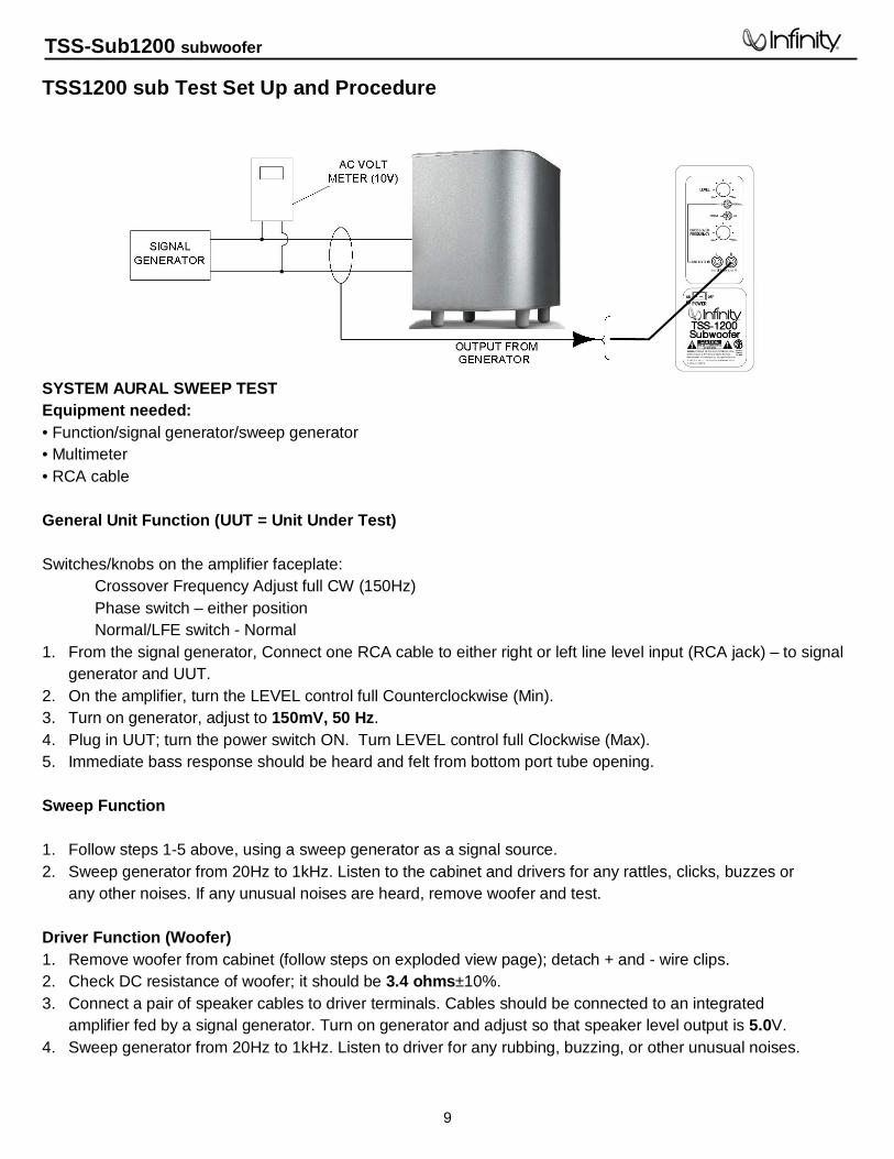
TSS1200 sub Test Set Up and Procedure
SYSTEM AURAL SWEEP TEST Equipment needed: • Function/signal generator/sweep generator • Multimeter • RCA cable General Unit Function (UUT = Unit Under Test) Switches/knobs on the amplifier faceplate:
Crossover Frequency Adjust full CW (150Hz) Phase switch – either position Normal/LFE switch - Normal
1. From the signal generator, Connect one RCA cable to either right or left line level input (RCA jack) – to signal generator and UUT.
2. On the amplifier, turn the LEVEL control full Counterclockwise (Min). 3. Turn on generator, adjust to 150mV, 50 Hz. 4. Plug in UUT; turn the power switch ON. Turn LEVEL control full Clockwise (Max). 5. Immediate bass response should be heard and felt from bottom port tube opening. Sweep Function 1. Follow steps 1-5 above, using a sweep generator as a signal source. 2. Sweep generator from 20Hz to 1kHz. Listen to the cabinet and drivers for any rattles, clicks, buzzes or
any other noises. If any unusual noises are heard, remove woofer and test. Driver Function (Woofer) 1. Remove woofer from cabinet (follow steps on exploded view page); detach + and - wire clips. 2. Check DC resistance of woofer; it should be 3.4 ohms±10%. 3. Connect a pair of speaker cables to driver terminals. Cables should be connected to an integrated
amplifier fed by a signal generator. Turn on generator and adjust so that speaker level output is 5.0V. 4. Sweep generator from 20Hz to 1kHz. Listen to driver for any rubbing, buzzing, or other unusual noises.
TSS-Sub1200 subwoofer
9
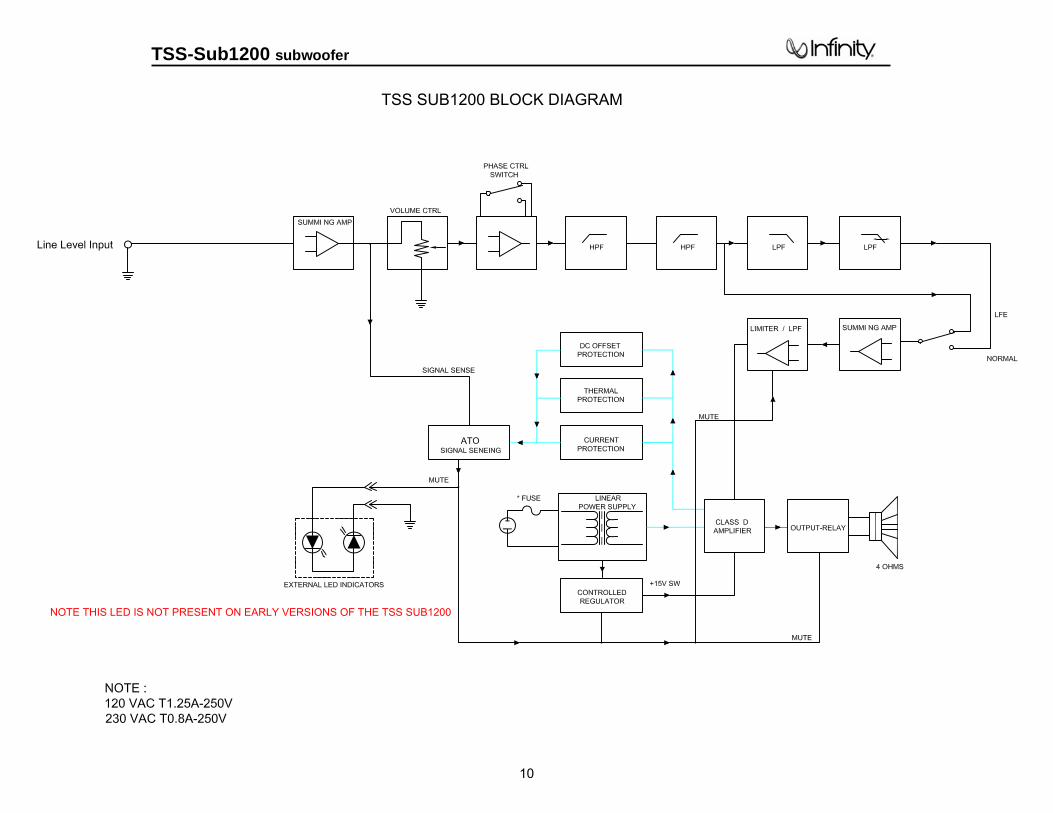
TSS SUB1200 BLOCK DIAGRAM
NOTE THIS LED IS NOT PRESENT ON EARLY VERSIONS OF THE TSS SUB1200
TSS-Sub1200 subwoofer
10

TSS- Sub1200 Subwoofer
11

TSS- Sub1200 Subwoofer
12
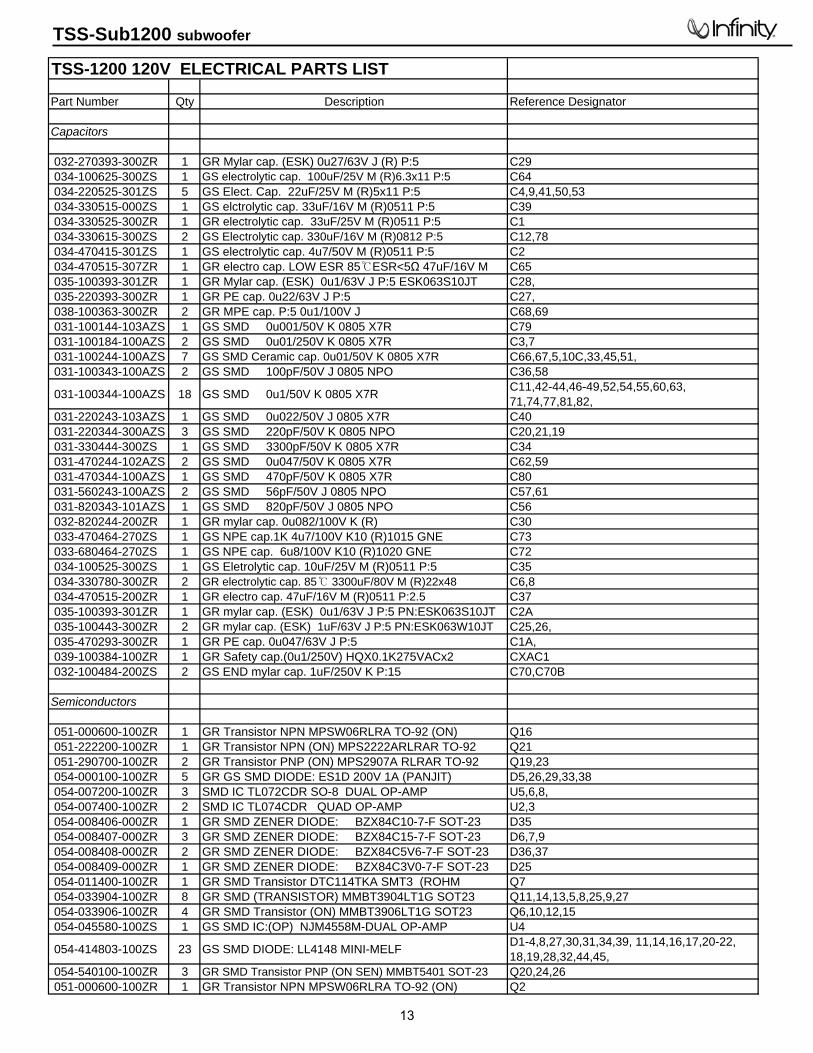
TSS-1200 120V ELECTRICAL PARTS LIST
Part Number Qty Description Reference Designator
Capacitors
032-270393-300ZR 1 GR Mylar cap. (ESK) 0u27/63V J (R) P:5 C29 034-100625-300ZS 1 GS electrolytic cap. 100uF/25V M (R)6.3x11 P:5 C64 034-220525-301ZS 5 GS Elect. Cap. 22uF/25V M (R)5x11 P:5 C4,9,41,50,53 034-330515-000ZS 1 GS elctrolytic cap. 33uF/16V M (R)0511 P:5 C39 034-330525-300ZR 1 GR electrolytic cap. 33uF/25V M (R)0511 P:5 C1 034-330615-300ZS 2 GS Electrolytic cap. 330uF/16V M (R)0812 P:5 C12,78 034-470415-301ZS 1 GS electrolytic cap. 4u7/50V M (R)0511 P:5 C2 034-470515-307ZR 1 GR electro cap. LOW ESR 85ESR<5Ω 47uF/16V M C65 035-100393-301ZR 1 GR Mylar cap. (ESK) 0u1/63V J P:5 ESK063S10JT C28, 035-220393-300ZR 1 GR PE cap. 0u22/63V J P:5 C27, 038-100363-300ZR 2 GR MPE cap. P:5 0u1/100V J C68,69 031-100144-103AZS 1 GS SMD 0u001/50V K 0805 X7R C79 031-100184-100AZS 2 GS SMD 0u01/250V K 0805 X7R C3,7 031-100244-100AZS 7 GS SMD Ceramic cap. 0u01/50V K 0805 X7R C66,67,5,10C,33,45,51, 031-100343-100AZS 2 GS SMD 100pF/50V J 0805 NPO C36,58
031-100344-100AZS 18 GS SMD 0u1/50V K 0805 X7R C11,42-44,46-49,52,54,55,60,63, 71,74,77,81,82,
031-220243-103AZS 1 GS SMD 0u022/50V J 0805 X7R C40 031-220344-300AZS 3 GS SMD 220pF/50V K 0805 NPO C20,21,19 031-330444-300ZS 1 GS SMD 3300pF/50V K 0805 X7R C34 031-470244-102AZS 2 GS SMD 0u047/50V K 0805 X7R C62,59 031-470344-100AZS 1 GS SMD 470pF/50V K 0805 X7R C80 031-560243-100AZS 2 GS SMD 56pF/50V J 0805 NPO C57,61 031-820343-101AZS 1 GS SMD 820pF/50V J 0805 NPO C56 032-820244-200ZR 1 GR mylar cap. 0u082/100V K (R) C30 033-470464-270ZS 1 GS NPE cap.1K 4u7/100V K10 (R)1015 GNE C73 033-680464-270ZS 1 GS NPE cap. 6u8/100V K10 (R)1020 GNE C72 034-100525-300ZS 1 GS Eletrolytic cap. 10uF/25V M (R)0511 P:5 C35 034-330780-300ZR 2 GR electrolytic cap. 85 3300uF/80V M (R)22x48 C6,8 034-470515-200ZR 1 GR electro cap. 47uF/16V M (R)0511 P:2.5 C37 035-100393-301ZR 1 GR mylar cap. (ESK) 0u1/63V J P:5 PN:ESK063S10JT C2A 035-100443-300ZR 2 GR mylar cap. (ESK) 1uF/63V J P:5 PN:ESK063W10JT C25,26, 035-470293-300ZR 1 GR PE cap. 0u047/63V J P:5 C1A, 039-100384-100ZR 1 GR Safety cap.(0u1/250V) HQX0.1K275VACx2 CXAC1 032-100484-200ZS 2 GS END mylar cap. 1uF/250V K P:15 C70,C70B
Semiconductors
051-000600-100ZR 1 GR Transistor NPN MPSW06RLRA TO-92 (ON) Q16 051-222200-100ZR 1 GR Transistor NPN (ON) MPS2222ARLRAR TO-92 Q21 051-290700-100ZR 2 GR Transistor PNP (ON) MPS2907A RLRAR TO-92 Q19,23 054-000100-100ZR 5 GR GS SMD DIODE: ES1D 200V 1A (PANJIT) D5,26,29,33,38 054-007200-100ZR 3 SMD IC TL072CDR SO-8 DUAL OP-AMP U5,6,8, 054-007400-100ZR 2 SMD IC TL074CDR QUAD OP-AMP U2,3 054-008406-000ZR 1 GR SMD ZENER DIODE: BZX84C10-7-F SOT-23 D35 054-008407-000ZR 3 GR SMD ZENER DIODE: BZX84C15-7-F SOT-23 D6,7,9 054-008408-000ZR 2 GR SMD ZENER DIODE: BZX84C5V6-7-F SOT-23 D36,37 054-008409-000ZR 1 GR SMD ZENER DIODE: BZX84C3V0-7-F SOT-23 D25 054-011400-100ZR 1 GR SMD Transistor DTC114TKA SMT3 (ROHM Q7 054-033904-100ZR 8 GR SMD (TRANSISTOR) MMBT3904LT1G SOT23 Q11,14,13,5,8,25,9,27 054-033906-100ZR 4 GR SMD Transistor (ON) MMBT3906LT1G SOT23 Q6,10,12,15 054-045580-100ZS 1 GS SMD IC:(OP) NJM4558M-DUAL OP-AMP U4
054-414803-100ZS 23 GS SMD DIODE: LL4148 MINI-MELF D1-4,8,27,30,31,34,39, 11,14,16,17,20-22, 18,19,28,32,44,45,
054-540100-100ZR 3 GR SMD Transistor PNP (ON SEN) MMBT5401 SOT-23 Q20,24,26 051-000600-100ZR 1 GR Transistor NPN MPSW06RLRA TO-92 (ON) Q2
TSS-Sub1200 subwoofer
13
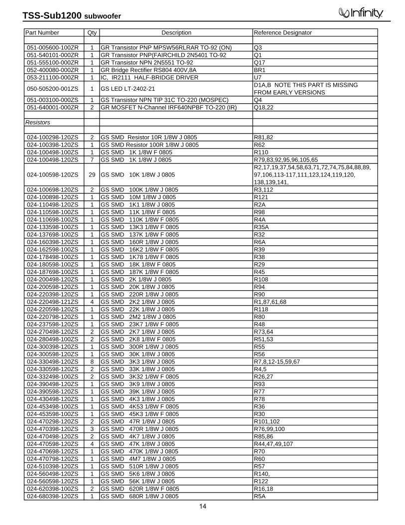
Part Number Qty Description Reference Designator
051-005600-100ZR 1 GR Transistor PNP MPSW56RLRAR TO-92 (ON) Q3 051-540101-000ZR 1 GR Transistor PNP(FAIRCHILD 2N5401 TO-92 Q1 051-555100-000ZR 1 GR Transistor NPN 2N5551 TO-92 Q17 052-400080-000ZR 1 GR Bridge Rectifier RS804 400V,8A BR1 053-211100-000ZR 1 IC, IR2111 HALF-BRIDGE DRIVER U7
050-505200-001ZS 1 GS LED LT-2402-21 D1A,B NOTE THIS PART IS MISSING FROM EARLY VERSIONS
051-003100-000ZS 1 GS Transistor NPN TIP 31C TO-220 (MOSPEC) Q4 051-640001-000ZR 2 GR MOSFET N-Channel IRF640NPBF TO-220 (IR) Q18,22
Resistors
024-100298-120ZS 2 GS SMD Resistor 10R 1/8W J 0805 R81,82 024-100398-120ZS 1 GS SMD Resistor 100R 1/8W J 0805 R62 024-100498-100ZS 1 GS SMD 1K 1/8W F 0805 R110 024-100498-120ZS 7 GS SMD 1K 1/8W J 0805 R79,83,92,95,96,105,65
024-100598-120ZS 29 GS SMD 10K 1/8W J 0805 R2,17,19,37,54,58,63,71,72,74,75,84,88,89, 97,106,113-117,111,123,124,119,120, 138,139,141,
024-100698-120ZS 2 GS SMD 100K 1/8W J 0805 R3,112 024-100898-120ZS 1 GS SMD 10M 1/8W J 0805 R121 024-110498-120ZS 1 GS SMD 1K1 1/8W J 0805 R2A 024-110598-100ZS 1 GS SMD 11K 1/8W F 0805 R98 024-110698-100ZS 1 GS SMD 110K 1/8W F 0805 R4A 024-133598-100ZS 1 GS SMD 13K3 1/8W F 0805 R35A 024-137698-100ZS 1 GS SMD 137K 1/8W F 0805 R32 024-160398-120ZS 1 GS SMD 160R 1/8W J 0805 R6A 024-162598-100ZS 1 GS SMD 16K2 1/8W F 0805 R39 024-178498-100ZS 1 GS SMD 1K78 1/8W F 0805 R38 024-180598-100ZS 1 GS SMD 18K 1/8W F 0805 R29 024-187698-100ZS 1 GS SMD 187K 1/8W F 0805 R45 024-200498-120ZS 1 GS SMD 2K 1/8W J 0805 R108 024-200598-120ZS 1 GS SMD 20K 1/8W J 0805 R94 024-220398-120ZS 1 GS SMD 220R 1/8W J 0805 R90 024-220498-121ZS 4 GS SMD 2K2 1/8W J 0805 R1,87,61,68 024-220598-120ZS 1 GS SMD 22K 1/8W J 0805 R118 024-220798-120ZS 1 GS SMD 2M2 1/8W J 0805 R80 024-237598-120ZS 1 GS SMD 23K7 1/8W F 0805 R48 024-270498-120ZS 2 GS SMD 2K7 1/8W J 0805 R73,64 024-280498-100ZS 2 GS SMD 2K8 1/8W F 0805 R51,53 024-300398-120ZS 1 GS SMD 300R 1/8W J 0805 R55 024-300598-120ZS 1 GS SMD 30K 1/8W J 0805 R56 024-330498-120ZS 8 GS SMD 3K3 1/8W J 0805 R7,8,12-15,59,67 024-330598-120ZS 2 GS SMD 33K 1/8W J 0805 R4,5 024-332498-100ZS 2 GS SMD 3K32 1/8W F 0805 R26,27 024-390498-120ZS 1 GS SMD 3K9 1/8W J 0805 R93 024-390598-120ZS 1 GS SMD 39K 1/8W J 0805 R77 024-430498-120ZS 1 GS SMD 4K3 1/8W J 0805 R78 024-453498-100ZS 1 GS SMD 4K53 1/8W F 0805 R36 024-453598-100ZS 1 GS SMD 45K3 1/8W F 0805 R30 024-470298-120ZS 2 GS SMD 47R 1/8W J 0805 R101,102 024-470398-120ZS 3 GS SMD 470R 1/8W J 0805 R76,99,100 024-470498-120ZS 2 GS SMD 4K7 1/8W J 0805 R85,86 024-470598-120ZS 4 GS SMD 47K 1/8W J 0805 R44,47,49,107 024-470698-120ZS 1 GS SMD 470K 1/8W J 0805 R70 024-470798-120ZS 1 GS SMD 4M7 1/8W J 0805 R60 024-510398-120ZS 1 GS SMD 510R 1/8W J 0805 R57 024-560498-120ZS 1 GS SMD 5K6 1/8W J 0805 R140, 024-560598-120ZS 1 GS SMD 56K 1/8W J 0805 R122 024-620398-100ZS 2 GS SMD 620R 1/8W F 0805 R16,18 024-680398-120ZS 1 GS SMD 680R 1/8W J 0805 R5A
TSS-Sub1200 subwoofer
14

Part Number Qty Description Reference Designator
024-680498-120ZS 6 GS SMD 6K8 1/8W J 0805 R46,91,40-43 024-680598-120ZS 6 GS SMD 68K 1/8W J 0805 R33,34A,31,50,52,66 024-820598-120ZS 1 GS SMD 82K 1/8W J 0805 R69 020-000098-400ZS 4 GS Carbon Film Resistor 0R 1/8W C22-24,31, 020-220497-120ZS 1 GS Carbon film resistor 2K2 1/4W J R11 021-100401-120ZS 1 GS MOF Resistor 1K 1W J INK MO-100 R103 021-220202-120ZS 1 GS MOF resistor 22R 2W(S) J MB TYPE 15x8 R10 021-240405-020ZS 4 GS MOF Resistor 2K4/5WS J 17x6 KINK R6,9,R7A,R9A 022-500003-020ZS 1 GS Resistor KNP 0R05 3WS J FK TYPE R104 026-200595-269ZS 1 GS VR PN:RD163121R03D-20KBx2(EJ) FREQUENCY VR2 026-500495-005ZS 1 GS VR 5K PN:RD163111R22B-5K15A-EJ LEVEL VR1
Miscellaneous
044-100100-000ZS 2 GS SMD FERRITE BEAD PN:321611 600R/100MHz 1206 FB1,FB2 041-115001-000ZR 1 GR BEAD COIL PN:YT-10911 L5 043-300101-000ZR 1 GR INDUCTOR PN:YT-10033 30uH L2 043-324300-000ZR 1 GR INDUCTOR 324uH YT-10778 L4 043-560200-000ZR 1 GR INDUCTOR 56uH YT-10779 L1 043-840100-000ZR 1 GR Inductor PN:YT-14389 84uH TSS1100/230V L3 072-010305-000ZS 1 GS RCA JACK PN:B217BK 2P CONN1 073-050001-000ZS 2 GS FUSE CLIP P/N:CT-FH1206 074-030002-000ZR 2 GR TOGGLE SW PN:L101-T2B4QE PHASE, LFE SW5,SW6 074-300018-000ZR 1 GR RELAY PN:943-1C-48D K1 077-100102-100ZR 1 GR PN:JS-1001-02 P:2.5 2P CONN3A 093-105202-300ZR 1 GR FUSE:UL GSL(2AG) FUSE:2A,250V,5*20mm F1 025-010300-000ZR 1 GR Thermister PN:NTSE103KZ072 K L:50mm TH1 042-010147-000ZR 1 GR Transformer PN:YT-15250 (TSS1100/120V) PT1 061-020000-000ZS 2 GS Knob ABS HTS-10/20 20x15m/m UL94V-0 BLK LEVEL, CROSSOVER 061-400014-000BZR 4 GR RUBBER FOOT ID:6.2 OD:11.5 t:2mm 55 BLK 061-700044-000ZR 3 GR Mica 13x18mm TO-220 for Q4,18,22 063-010012-000ZR 4 GR Bracket for Transistor P/N:TRK-1 ICx4 063-321101-000ZR 1 GR Panel 322x105.7x15mm BLK ABS-94V0 063-531808-000ZR 1 GR bucket (PB-10/12) ABS 322x105.7x146.5mm BLK (94VO) 073-011006-400ZR 2 GR BRACKET 16x34mm t:0.8mm PANELx2 073-032315-601ZS 1 GS HeatSink 70x58x20mm Alum. (PB-12) 074-020018-000ZR 1 GR ROCKER SW (POWER) PN:RF1003-BB4-0 086-021818-005ZR 1 GR Power Cord NISPT-2 18AWGx2 L:1830mm 105C+T187 230V VERSION DIFFERENCES
086-021818-030BZR 1 Power Cord VDE 6 feet long093-205201-320ZR 1 Fuse VBSUTE 1.25A/250V 5mm*20mm F1042-010148-000ZR 1 GR Transformer YT-15251 PT1
TSS-Sub1200 subwoofer
15

TSS-Sub1200 subwoofer
16

TSS-Sub1200 subwoofer
17

NOTE THIS LED IS NOT PRESENT ON EARLY VERSIONS OF THE TSS SUB1200
TSS-Sub1200 subwoofer
18