dvs vertical lift (double v...
TRANSCRIPT

CAUTION - PUT SAFETY FIRST
Before attempting to install or operate this lift, study and fully understand the proper operating
procedures and safety precautions outlined in this owner's manual.
Never exceed the recommended weight capacity of your lift. The lifted weight will include hull,
engine, fuel, battery, and added accessories or gear. Weigh your fully loaded boat at a certified
scale to be absolutely sure of the total weight.
Do not allow anyone on, in, or under the lift while operating.
NOT COMPLYING WITH THE PROCEDURES AND PRECAUTIONS OUTLINED IN THIS MANUAL
WILL INVALIDATE THE WARRANTY AND MAY RESULT IN PERSONAL INJURY OR DEATH.
If you have any questions about assembly, installation, operation or suitability of this product,
contact an authorized dealer.
1.
2.
3.
4.
5.
www.shoremaster.com
DVS Vertical Lift
(Double V Side):
Frame Assembly Instructions.
Models:
4010DVS - 10ft Wide Pontoon, 4000 Capacity - Part #: 1024524 - 1024851(with Pontoon Guide/Cradles)
5010DVS - 10ft Wide, 5000lb Capacity - Part #: 1007119
6010DVS - 10ft Wide, 6000lb Capacity - Part #: 1020833
Published: 12-4-13
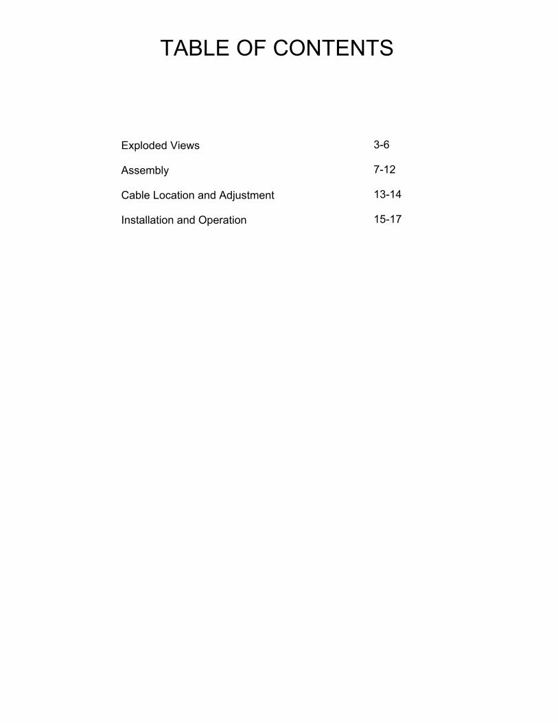
TABLE OF CONTENTS
Exploded Views Assembly Cable Location and Adjustment Installation and Operation
3-6 7-12 13-14 15-17

*1020835 - Hardware Box 5/6000 DVS Lift*
DESCRIPTIONPART NUMBERQTYITEM
Winch Mount Clamp100179111
Press-In Cap 3 x 3100103442
Hardware Bag (Pins)10075181
-
Pin 3/8 X 3-29/32100260043
Hair Pin Keeper100227844
Bolt Bag (Frame)10208601
-
Bolt 3/8 x 4.251002443225
Washer Flat 3/81002599306
Bolt 3/8 x 3.5100243447
Nut Nyloc 1/2100179578
Washer Flat 1/2100256559
Bolt 3/8 x 1.251002422810
Bolt Carriage 3/8 x 1.751001959411
Nut Flange 3/810018024512
Bolt 3/8 x 4.51002441413
Bolt 3/8 x 2.751002431314
Bolt Hex 1/2-13 x 4.5 SS 3041002385215
Whisper Winch Model 2411015523116
Hardware Bag Winch10044881
-
Bolt Custom 1/2 x 1.0 1000513217
Set Screw 3/8 x 3/81000536218
*1024541 - Bundle 4010 Pontoon DVS Vertical Lift*
DESCRIPTIONPART NUMBERQTYITEM
Lift Side Opposite1024533119
Lift Side Winch1024532120
Foot Pad - C1007404421
Leg Post - C31003944422
Brace Tube1003084423
Bottom Beam (10ft)1003652224
Right Rack Side Assembly1024526125
Right Rack Side - Alum Only10245281
Left Rack Side Assembly1024525126
Side Cable10245311
Left Rack Side - Alum Only10245271
Front Rack Assembly (10ft)1003381127
Front Rack - Alum Only10036581
Winch Cable (10ft)10076811
Rack Rear Assembly (10ft)1003385128
Rear Cable (10ft)10033882
Rack Rear - Alum Only 10036621
Rack/Pulley Parts
DESCRIPTIONPART NUMBERQTY
Brass Sheave 3.75 (Front/Rear)10069166
Brass Sheave 3.75 (Side)10069164
Bushing (Front)10069074
Bushing (Rear)10069094
Bushing (Side)10022058
Vertical Roller10027068
Cable Roller10009532
Cable Roller Shaft10009522
Double V Side 4010
DVS Pontoon Vertical Lift
Part Number: 1024524
Parts List "B"
Parts List "A"
Shipping Information
Description Weight
Dimensions Cubic Ft
Bundle 450 9"-11" x 96" x 164" 100.22
Hardware Box
4010DVS Pontoon Complete EXP.idw
1
A
2
A
3
A
4
A
5
A
6
A
7
A
8
A
9
A
10
A
11
A
12
A
13
A
14
A
15
A
16
A
18
A
17
A
19
B
20
B
21
B
22
B
23
B
24
B
25
B
26
B
27
B
28
B

Parts List
DESCRIPTIONPART NUMBERQTYITEM
Pontoon Guide - Cradle Bracket 4K Complete (Set of 4)102469511
Lift Vertical 4010 Pontoon DVS102452412
12/4/2013
1024851 - Pontoon 4010 DVS with Pontoon
guide - cradle.idw
Part # 1024851
Pontoon 4010 DVS with Pontoon
Guide / Cradles
2
1

*1016151 - Hardware Box 4/5000 DVS Lift*
DESCRIPTIONPART NUMBERQTYITEM
Press-In Cap 3 x 3100103442
Winch Mount Clamp100179111
Hardware Bag (Pins)10075181
-
Pin 3/8 X 3-29/32100260043
Hair Pin Keeper100227844
Bolt Bag (Frame)10044841
-
Bolt 3/8 x 4.251002443225
Washer Flat 3/81002599326
Bolt 3/8 x 3.5100243447
Nut Nyloc 1/2100179578
Washer Flat 1/2100256559
Bolt 3/8 x 1.251002422810
Bolt Carriage 3/8 x 1.751001959411
Nut Flange 3/810018024512
Bolt 3/8 x 4.51002441413
Bolt 3/8 x 2.751002431314
Whisper Winch Model 2411015523115
Hardware Bag Winch10044881
-
Bolt Custom 1/2 x 1.0 1000513216
Set Screw 3/8 x 3/81000536217
Bolt Hex 1/2-13 x 4.51002385218
*1003941 - Bundle 5010 DVS-V Vertical Lift*
DESCRIPTIONPART NUMBERQTYITEM
Lift Side Opposite1003651118
Lift Side Winch1003650119
Foot Pad - C1007404420
Leg Post - C31003944421
Brace Tube1003084422
Bottom Beam (10ft)1003654223
Right Rack Side Assembly1003389124
Right Rack Side - Alum Only10036631
Left Rack Side Assembly1003390125
Side Cable10076721
Left Rack Side - Alum Only10036641
Front Rack Assembly (10ft)1003391126
Front Rack - Alum Only10036651
Winch Cable (10ft)10076811
Rack Rear Assembly (10ft)1003392127
Rear Cable (10ft)10033882
Rack Rear - Alum Only 10036661
Rack/Pulley Parts
DESCRIPTIONPART NUMBERQTY
Brass Sheave 3.5 10046576
Brass Sheave 3.75 (Side)10069164
Bushing (Front)10069074
Bushing (Rear)10069094
Bushing (Side)10022058
Vertical Roller10027068
Cable Roller10009532
Cable Roller Shaft10009522
ShoreMaster Double V Side
5010DVS-V - Vertical Lift
Part Number: 1007119
Parts List "B"
Parts List "A"
3
A
4
A
5
A
6
A
13
A
7
A
8
A
9
A
10
A
11
A
12
A
18
B
19
B
20
B
21
B
22
B
23
B
24
C
25
B
26
B
Shipping Information
Description Weight
Dimensions Cubic Ft
Bundle 446 9"-11" x 96" x 116" 70.89
Hardware Box
2
A
17
A
1
A
16
A
15
A
14
A
18
A
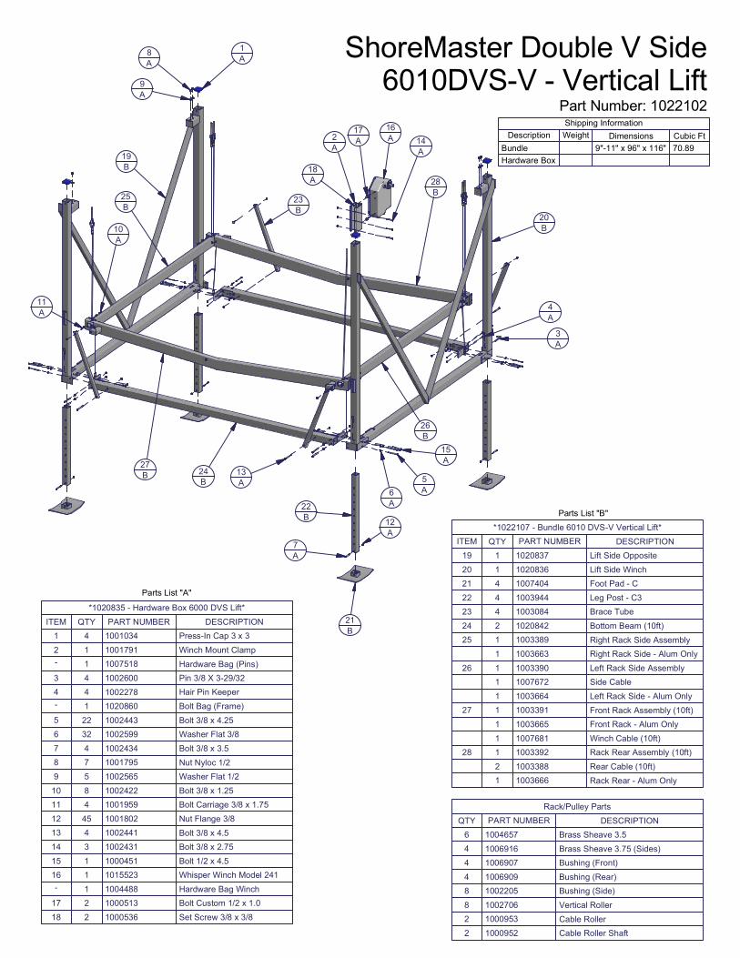
*1020835 - Hardware Box 6000 DVS Lift*
DESCRIPTIONPART NUMBERQTYITEM
Press-In Cap 3 x 3100103441
Winch Mount Clamp100179112
Hardware Bag (Pins)10075181
-
Pin 3/8 X 3-29/32100260043
Hair Pin Keeper100227844
Bolt Bag (Frame)10208601
-
Bolt 3/8 x 4.251002443225
Washer Flat 3/81002599326
Bolt 3/8 x 3.5100243447
Nut Nyloc 1/2100179578
Washer Flat 1/2100256559
Bolt 3/8 x 1.251002422810
Bolt Carriage 3/8 x 1.751001959411
Nut Flange 3/810018024512
Bolt 3/8 x 4.51002441413
Bolt 3/8 x 2.751002431314
Bolt 1/2 x 4.51000451115
Whisper Winch Model 2411015523116
Hardware Bag Winch10044881
-
Bolt Custom 1/2 x 1.0 1000513217
Set Screw 3/8 x 3/81000536218
*1022107 - Bundle 6010 DVS-V Vertical Lift*
DESCRIPTIONPART NUMBERQTYITEM
Lift Side Opposite1020837119
Lift Side Winch1020836120
Foot Pad - C1007404421
Leg Post - C31003944422
Brace Tube1003084423
Bottom Beam (10ft)1020842224
Right Rack Side Assembly1003389125
Right Rack Side - Alum Only10036631
Left Rack Side Assembly1003390126
Side Cable10076721
Left Rack Side - Alum Only10036641
Front Rack Assembly (10ft)1003391127
Front Rack - Alum Only10036651
Winch Cable (10ft)10076811
Rack Rear Assembly (10ft)1003392128
Rear Cable (10ft)10033882
Rack Rear - Alum Only 10036661
Rack/Pulley Parts
DESCRIPTIONPART NUMBERQTY
Brass Sheave 3.5 10046576
Brass Sheave 3.75 (Sides)10069164
Bushing (Front)10069074
Bushing (Rear)10069094
Bushing (Side)10022058
Vertical Roller10027068
Cable Roller10009532
Cable Roller Shaft10009522
ShoreMaster Double V Side
6010DVS-V - Vertical Lift
Part Number: 1022102
Parts List "B"
Parts List "A"
3
A
4
A
5
A
6
A
13
A
7
A
8
A
9
A
10
A
11
A
12
A
19
B
20
B
21
B
22
B
23
B
24
B
25
B
26
B
27
B
Shipping Information
Description Weight
Dimensions Cubic Ft
Bundle 9"-11" x 96" x 116" 70.89
Hardware Box
1
A
18
A
2
A
17
A
16
A
14
A
15
A
28
B

DETAIL A
A
Your safety is the most important issue related to this product. For ease of assembly find a flat area with plenty of room to assemble lift. The following tools will be needed for assembling lift: Only hand tighten bolts and nuts until lift is completely assembled. STEP 1Press in Blue Caps on Uprights as shown. Insert all four Leg Posts into Foot Pads. Secure using one Bolt 3/8 x 3.5 and one Nut 3/8 in each place. Insert Leg Posts into Lift Sides as shown. Secure with one Pin 3/8 x 3 29/32 and one Hair Pin for each Leg Post. No washers are used at this time.
• Fully read and understand each step before proceeding with that step.• Wear protective gloves, clothing and eyewear when assembling and installing the lift.• Do not assemble, install or use this product if items are missing or damaged. 1. Pair of 7/16” Wrenches2. Pair of 9/16” Wrenches3. 3/4” Wrench4. Measuring Tape5. Hammer6. 3/16” Allen Wrench
Frame Assembly Instructions
Leg Post
Bolt 3/8 x 3.5
Foot Pad
Nut Flange 3/8
Pin 3/8 x 3 29/32
Hair Keeper
Lift SideUpright
Blue Cap
DETAIL A(Front)
DETAIL B(Front)
DETAIL D(Rear)DETAIL C
(Rear)
A
B
D
C
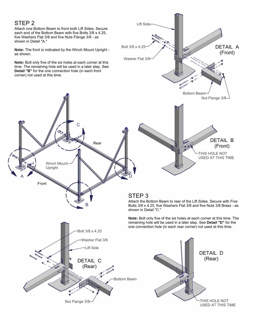
STEP 2Attach one Bottom Beam to front both Lift Sides. Secure each end of the Bottom Beam with five Bolts 3/8 x 4.25, five Washers Flat 3/8 and five Nuts Flange 3/8 - as shown in Detail "A." Note: The front is indicated by the Winch Mount Upright -as shown. Note: Bolt only five of the six holes at each corner at this time. The remaining hole will be used in a later step. See Detail "B" for the one connection hole (in each front corner) not used at this time.
STEP 3Attach the Bottom Beam to rear of the Lift Sides. Secure with Five Bolts 3/8 x 4.25, five Washers Flat 3/8 and five Nuts 3/8 Brass - as shown in Detail "C." Note: Bolt only five of the six holes at each corner at this time. The remaining hole will be used in a later step. See Detail "D" for the one connection hole (in each rear corner) not used at this time.
Winch Mount Upright
Bolt 3/8 x 4.25
Washer Flat 3/8
Nut Flange 3/8Bottom Beam
Lift Side
THIS HOLE NOT USED AT THIS TIME
Lift Side
Bolt 3/8 x 4.25
Washer Flat 3/8
Bottom Beam
Nut Flange 3/8
Front
Rear
THIS HOLE NOT USED AT THIS TIME

DETAIL B
DETAIL A
B
A
STEP 4Attach the Brace Tube to the Lift Sides and Bottom Beams. Secure each Brace Tube to the Bottom Beams with one Bolt 3/8 x 4.5, and one Nut Flange 3/8 - as shown in Detail "A." Secure each Brace Tube to the T Slot of the Lift Sides with one Bolt Carriage 3/8 x 1.75 and one Nut Flange 3/8 - as shown in Detail "B."
Note: Take two measurements between the two LIft Sides, one at the top and one at the bottom. The measurement should be the same at the top and bottom of the Lift Sides.
Nut Flange 3/8
Brace Tube
Lift Side
T-Slot
Bolt Carriage 3/8 x 1.75
Brace Tube
Bolt 3/8 x 4.5
Bottom Beam
Nut Flange 3/8
DETAIL ADETAIL B
A
B
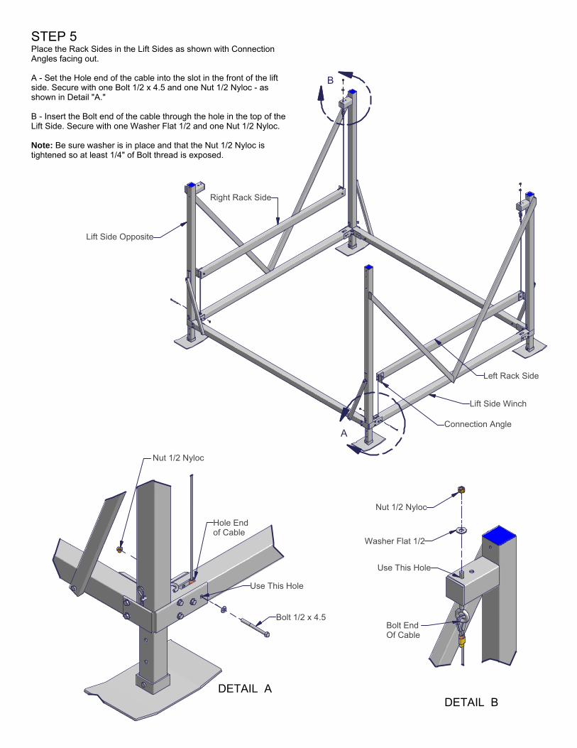
STEP 5Place the Rack Sides in the Lift Sides as shown with Connection Angles facing out. A - Set the Hole end of the cable into the slot in the front of the lift side. Secure with one Bolt 1/2 x 4.5 and one Nut 1/2 Nyloc - as shown in Detail "A." B - Insert the Bolt end of the cable through the hole in the top of the Lift Side. Secure with one Washer Flat 1/2 and one Nut 1/2 Nyloc. Note: Be sure washer is in place and that the Nut 1/2 Nyloc is tightened so at least 1/4" of Bolt thread is exposed.
Lift Side Opposite
Lift Side Winch
Right Rack Side
Left Rack Side
Bolt 1/2 x 4.5
Use This Hole
Hole End of Cable
Nut 1/2 Nyloc
Nut 1/2 Nyloc
Washer Flat 1/2
Use This Hole
Bolt End Of Cable
Connection Angle

DETAIL A
DETAIL B
DETAIL C
A
B
C
STEP 6A - Attach the Rear Rack to the Rack Sides. Secure at each end with two Bolts 3/8x 1.25, two Washers Flat 3/8 and two Nuts Flange 3/8 - as shown in Detail "A." B - Secure Hole end of cable to the Lift Side with one Bolt 3/8 x 4.25, one Washer Flat 3/8 and one Nut Flange 3/8 - as shown in Detail "B." C - Insert the Bolt of the Rear Rack cables through the hole in the top of the Lift Sides. Secure each cable with one Washer Flat 1/2 and one Nut 1/2 Nyloc as shown in Detail "C."
Bolt 3/8 x 1.25
Washer Flat 3/8
Nut Flange 3/8
Rack Side
Rear Rack
Bolt 3/8 x 4.25
Washer Flat 3/8
Nut Flange 3/8
Hole endof cable
Use This Hole
Nut Nyloc 1/2
Washer Flat 1/2
Use This Hole forRear Rack Cable
Bolt End of Cable

DETAIL A
DETAIL B
DETAIL C
A
B
C
STEP 7Set the Front Rack in place and attach to the Rack Sides. At each end secure withone Bolt 3/8 x 1.25, two Washers Flat 3/8 and one Nut Flange 3/8 in two places asshown in Detail "A." Insert the Eye Bolt of the Front Rack cable through the hole in the top of the Lift Sides. Secure with one Washer Flat 1/2 and one Nut 1/2 Nyloc Brass as shown in Detail "B." The other end of the cable is attached to the winch as shown in Winch/Wheel Instructions (included with the winch). Note: There are five Eye Bolts to attach. See the drawing of Eye Bolts and cables on next page to ensure correct location.
Nut Nyloc 1/2
Washer Flat 1/2
Bolt End of Front Rack Cable
Bolt 3/8 x 1.25
Washer Flat 1/2
Nut Flange 3/8
Rack Side
Front Rack Beam
STEP 8Slide Winch Mount onto Lift Side Winch Upright with the bolt holes facing the front of the lift (the left side of the lift when facing the Lift Side Winch). Secure Winch Mount by usingthree Bolts 3/8 x 2.75 and three Nuts Flange 3/8 - as shown in Detail "C." The Winch Mount is attached to the Lift Side Winch Upright that is 12" longer than the three other Uprights, and the top should be flush with the top of Lift Side Winch Upright. Note: On the 3000 Lifts with the Silent Brake Winch, this step must be done with the winch installed on the Winch Mount Clamp. STEP 9Now firmly tighten all nuts and bolts. Note: Nylon Locking Nuts (Nuts Nyloc) should not be reused, if one is removed it should be replaced with a new one.
Upright
Nut Flange 3/8
Bolt 3/8 x 2.75
Winch Mount Clamp

Proper Cable Locations
CAUTIONBe sure washer is in place and that Nyloc Nut is tightened so at least 1/4" is exposed. Failure to attachcables, Eye Bolts, Washers and Nyloc Nuts correctly could result in a severe crushing, cutting or pinchinginjury. Severe damage to lift or boat could also occur.
Front of Lift
Left Rack Side Cable Attached Here
Rear Rack Cable
Attached here
Front Rack (winch) Cable Eye Bolt
Right Rack Side Cable Eye Bolt
Rear Rack Cable Eye Bolt
Left Rack Side Cable Eye Bolt
DETAIL A
A
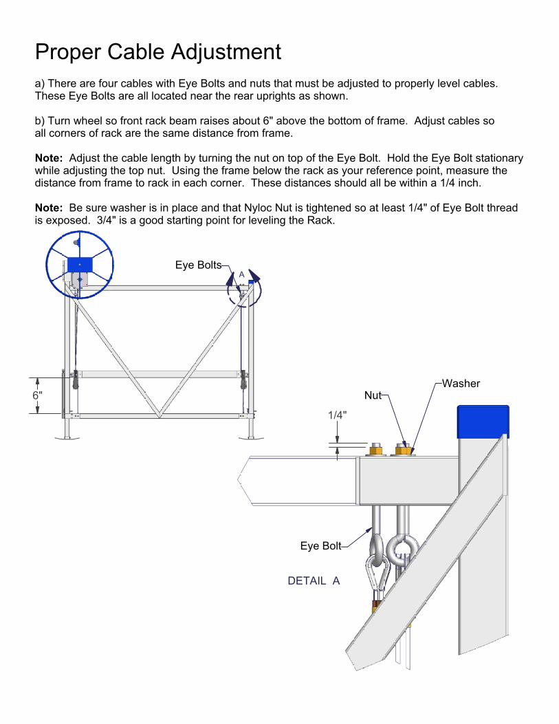
Proper Cable Adjustment a) There are four cables with Eye Bolts and nuts that must be adjusted to properly level cables.These Eye Bolts are all located near the rear uprights as shown. b) Turn wheel so front rack beam raises about 6" above the bottom of frame. Adjust cables so all corners of rack are the same distance from frame. Note: Adjust the cable length by turning the nut on top of the Eye Bolt. Hold the Eye Bolt stationary while adjusting the top nut. Using the frame below the rack as your reference point, measure the distance from frame to rack in each corner. These distances should all be within a 1/4 inch. Note: Be sure washer is in place and that Nyloc Nut is tightened so at least 1/4" of Eye Bolt threadis exposed. 3/4" is a good starting point for leveling the Rack.
6"
1/4"
NutWasher
Eye Bolt
Eye Bolts

INSTALLATION INSTRUCTIONS Do not under any circumstances, endanger yourself or risk damage to your lift or boat when installing. • Situations will widely vary between installation sites. ShoreMaster recommends that your
dealer or other trained boat lift installer train you and perform the initial installation. • Wear protective gloves, clothing and eyewear when assembling and installing the lift. • Do not assemble, install or use this product if items are missing or damaged.
The following are guidelines or suggestions for installation:
STEP 1 Measure the water depth of the position you want to locate the lift. Measurements should be taken at both the projected position of the end nearest shore and end furthest from shore.
STEP 2 Before installing, adjust lift legs so the boat can float into position before raising, while still allowing a high enough position so the boat can be fully raised up and out of the water.
STEP 3 Carry, lift, roll, float or slide the lift into position alongside the dock. Ask your dealer about a wheel caddy unit to allow your lift to be rolled into position.
STEP 4 Ensure that your lift is level. Measure the distance from the top of the cross beam to the water surface. The distance at each of the four corners of the lift should be within two inches of each other. If they are not, adjust the legs accordingly. Note: If the lift legs will extend 3 feet or more, ShoreMaster recommends deep water
braces to stabilize and strengthen the lift. Ask your dealer for more information.
STEP 5 After loading and operating the lift pursuant to the operating instructions, remove the boat and recheck that the lift remains level.
CAUTION The lift must be resting on the water bottom in a level, secure and stable position for safe operation. An unstable lift installation could result in tipping of the lift during operation, causing damage to watercraft and a crushing or pinching injury to the operator or bystanders.
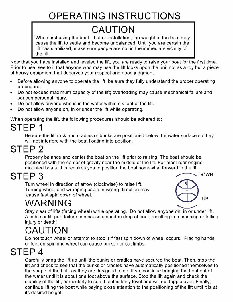
OPERATING INSTRUCTIONS
Now that you have installed and leveled the lift, you are ready to raise your boat for the first time. Prior to use, see to it that anyone who may use the lift looks upon the unit not as a toy but a piece of heavy equipment that deserves your respect and good judgment.
• Before allowing anyone to operate the lift, be sure they fully understand the proper operating procedure.
• Do not exceed maximum capacity of the lift; overloading may cause mechanical failure and serious personal injury.
• Do not allow anyone who is in the water within six feet of the lift. • Do not allow anyone on, in or under the lift while operating.
When operating the lift, the following procedures should be adhered to:
STEP 1 Be sure the lift rack and cradles or bunks are positioned below the water surface so they will not interfere with the boat floating into position.
STEP 2 Properly balance and center the boat on the lift prior to raising. The boat should be positioned with the center of gravity near the middle of the lift. For most rear engine mounted boats, this requires you to position the boat somewhat forward in the lift.
STEP 3 Turn wheel in direction of arrow (clockwise) to raise lift. Turning wheel and wrapping cable in wrong direction may cause fast spin down of wheel.
WARNING Stay clear of lifts (facing wheel) while operating. Do not allow anyone on, in or under lift. A cable or lift part failure can cause a sudden drop of boat, resulting in a crushing or falling injury or death!
CAUTION Do not touch wheel or attempt to stop it if fast spin down of wheel occurs. Placing hands or feet on spinning wheel can cause broken or cut limbs.
STEP 4 Carefully bring the lift up until the bunks or cradles have secured the boat. Then, stop the lift and check to see that the bunks or cradles have automatically positioned themselves to the shape of the hull, as they are designed to do. If so, continue bringing the boat out of the water until it is about one foot above the surface. Stop the lift again and check the stability of the lift, particularly to see that it is fairly level and will not topple over. Finally, continue lifting the boat while paying close attention to the positioning of the lift until it is at its desired height.
CAUTION When first using the boat lift after installation, the weight of the boat may cause the lift to settle and become unbalanced. Until you are certain the lift has stabilized, make sure people are not in the immediate vicinity of the lift.
DOWN
UP

CAUTIONS: 1. Do not over raise lift rack. Stop before top of rack hits cable loops attached to Eye Bolts. Over raising could cause damage to winch, cables or other parts. 2. Do not over lower rack so slack develops in cable. Doing this could cause cable to jump off winchspool. This may result in sloppy wrapping of cable next time you raise the lift, resulting in prematurewear or cable breaking.Turn wheel down one or two turns past point when craft begins to float (Thismust always be at some point before lift rack is contacting rear bottom beam). Then turn wheel upslightly until clicking sound is heard to secure wheel position and brake on winch. 3. Properly cover your boat, or pull your boat's plug when the boat is in a raised position. Rain water accumulating in your bilge can quickly increase your gross weight over the capacity of the lift. 4. Do not leave lift, or boat on lift, in water if ice formation is possible. Ice can severely damage your boatlift.
STEP 5 After loading and operating the lift, remove the boat and recheck that the lift remains level. (See Step 4 of the Installation Instructions.) If the lift is not level, the legs should be adjusted accordingly. Because the lift may settle and become unbalanced, the lift levelness should be rechecked two weeks after installation and periodically as needed.
STEP 6 If lift is without a boat in it for more than one day, raise the rack (pulleys) fully out of the water to help prevent corrosion of these parts. At all times, make sure the boat is stored high enough out of the water to avoid wave action against the hull. A moving boat as a result of wave action will damage the lift and can take the boat off the lift.
Monthly ChecksCheck cables for frays, corrosion or breaks at least once a month. A cable breaking while boat is in lift could damage boat or lift. Severe bodily injury could also occur.
SAFETY MAINTENANCE
1. Inspect nuts and bolts for damage, wear or loose connections. Tighten or replace parts as needed. 2. Inspect lift frame, pulleys, winch and pivot points for unusual wear, damage or bent parts. Replace or repair as needed. 3. Check that the rack is level with the bottom frame of your lift. Cable stretching or settling of lift couldrequire you to adjust nuts on Eye-Bolts. 4. Lubricate winch and wheel threads. Do not get lubricant on brakepads! Brake will fail and wheel willspin down if brake pads are lubricated. 5. Check and lubricate pulleys to ensure that they are turning freely. 6. Check Eye-Bolts to make sure they are not working themselves loose. ShoreMaster dealers usually offer service visits. Please contact them if you are unable or unwillingto perform maintenance or service to lift.~
Spring and Fall Checks