dxa crash course for technologists and clinicians
TRANSCRIPT

DXA Crash Course for Technologists and Clinicians
Santa Fe Bone SymposiumAugust 16, 2014
Diane Krueger, BS, CBDT

Learning Objectives
• Basic quality assurance measures that assess
scanner performance and allow for accurate reporting
of bone density results.
• Common errors on bone density scans and the impact
on reported results and clinical care.
• How ICD-10 coding and legislation could impact DXA
reimbursement.

Quality Assurance Concepts
• The clinician, technologist or manager need to
assure that QA and phantom scans are performed,
analyzed and evaluated to assure quality DXA
results
Daily Instrument Quality Control
Regular phantom scanning and evaluation
Precision assessment
Cross calibration

Perform Instrument Quality
Assurance Each Day Scanner is Used
• ISCD Official Position recommends routine QC
The Quality Control (QC) program at a DXA facility should
include adherence to manufacturer guidelines for system
maintenance.
• Most manufacturers require QC be run each
day before patients are scanned
ISCD Official Positions www.iscd.org
QA Block and Phantom Have
Different Duties • QA block validates calibration
o GE and Norland have external devices (QA block) to validate calibration
o Hologic uses internal hardware
• All densitometers have external phantoms to monitor
BMD, BMC and area measurements
Lunar QA Block
Lunar Water
Bath Phantom
Encapsulated phantoms
GE, Hologic BioClinica

GE Lunar Quality Control Should be
Run Each Day Scans are Obtained• Software only requires every 72 hours, however
best practice is to run each day scanning occurs
QA only requires black block be scanned
• Software will pass or fail calibration and plot
cumulative block measurement
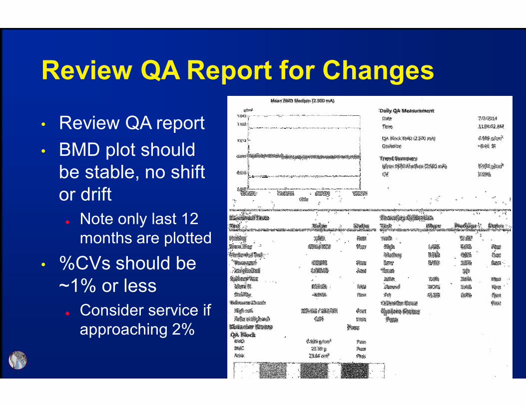
Review QA Report for Changes
• Review QA report
• BMD plot should
be stable, no shift
or drift
Note only last 12
months are plotted
• %CVs should be
~1% or less
Consider service if
approaching 2%

Hologic Quality Control Includes
Phantom Scanning• Hologic Apex software requires QC be run every
24 hours
Includes an internal calibration step and external
phantom scanning
• Software will pass or fail calibration and generate
phantom measurements
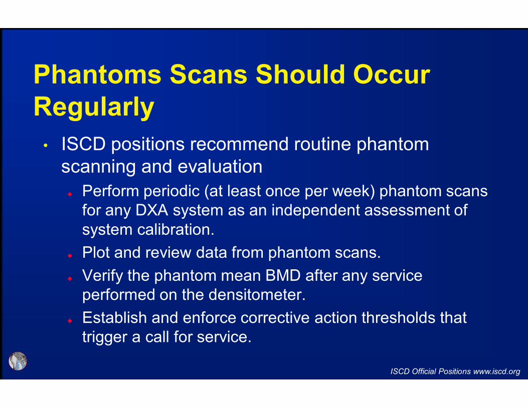
Phantoms Scans Should Occur
Regularly
• ISCD positions recommend routine phantom
scanning and evaluation
Perform periodic (at least once per week) phantom scans
for any DXA system as an independent assessment of
system calibration.
Plot and review data from phantom scans.
Verify the phantom mean BMD after any service
performed on the densitometer.
Establish and enforce corrective action thresholds that
trigger a call for service.
ISCD Official Positions www.iscd.org

Determine Phantom Mean and 1.5%
Thresholds for BMD, BMC and Area
• Scan a phantom 10-25 times and calculate BMD,
BMC and Area means for baseline comparison
Calculate 1.5% of mean for upper and lower limits
Plot values regularly (weekly or monthly) and watch for
drift toward threshold limits or shift outside limits
An occasional irregular value is not of concern, however,
steady drifts, stable shift or routine erroneous
measurements should prompt service to avoid scanner
shut down
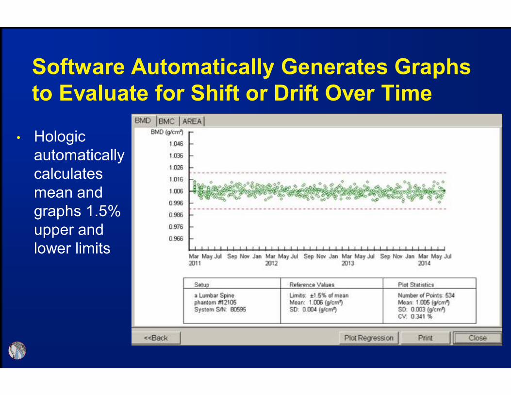
Software Automatically Generates Graphs
to Evaluate for Shift or Drift Over Time
• Hologic
automatically
calculates
mean and
graphs 1.5%
upper and
lower limits
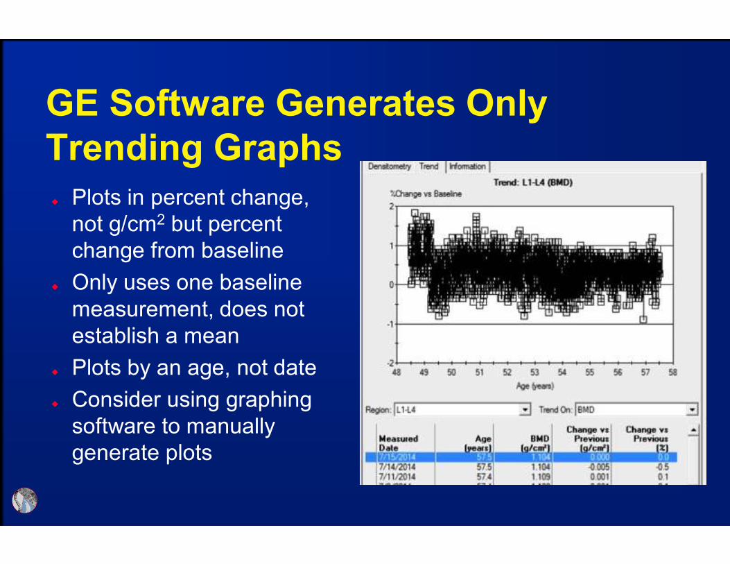
GE Software Generates Only
Trending Graphs
Plots in percent change,
not g/cm2 but percent
change from baseline
Only uses one baseline
measurement, does not
establish a mean
Plots by an age, not date
Consider using graphing
software to manually
generate plots
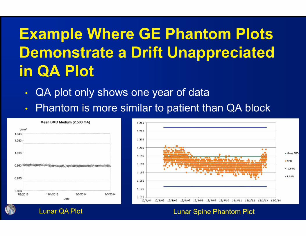
Example Where GE Phantom Plots
Demonstrate a Drift Unappreciated
in QA Plot
• QA plot only shows one year of data
• Phantom is more similar to patient than QA block
Lunar QA Plot Lunar Spine Phantom Plot
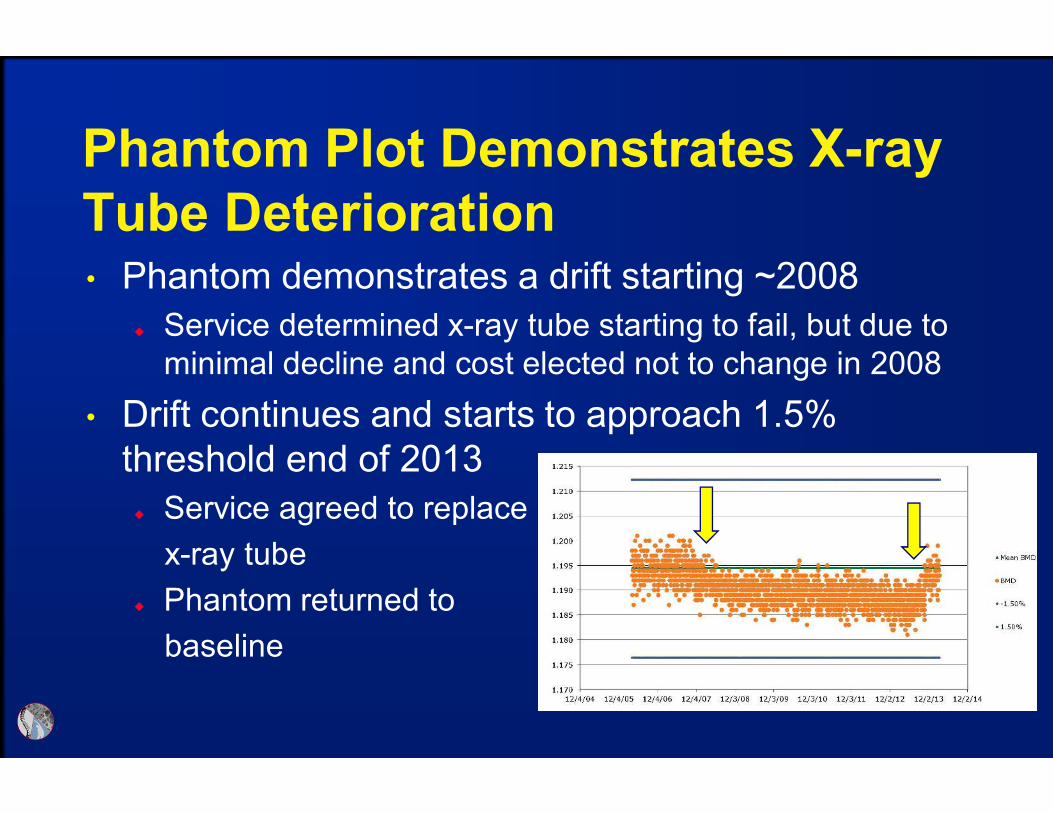
Phantom Plot Demonstrates X-ray
Tube Deterioration• Phantom demonstrates a drift starting ~2008
Service determined x-ray tube starting to fail, but due to
minimal decline and cost elected not to change in 2008
• Drift continues and starts to approach 1.5%
threshold end of 2013
Service agreed to replace
x-ray tube
Phantom returned to
baseline
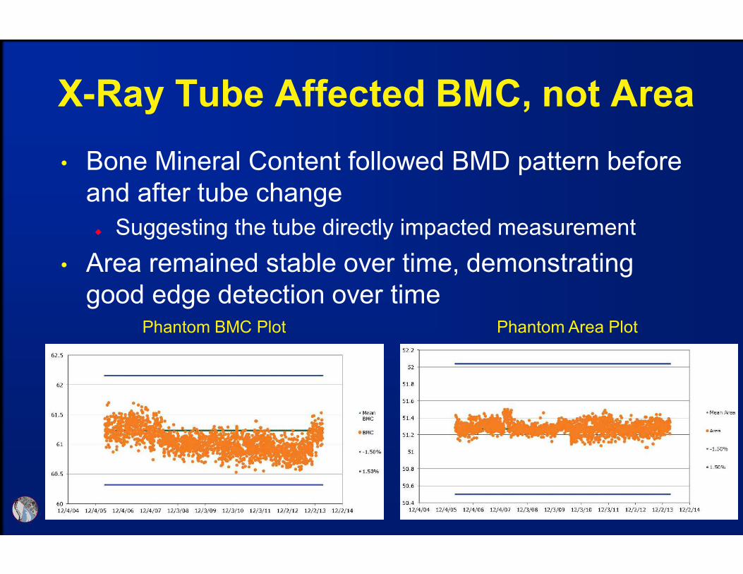
Phantom BMC Plot Phantom Area Plot
X-Ray Tube Affected BMC, not Area
• Bone Mineral Content followed BMD pattern before
and after tube change
Suggesting the tube directly impacted measurement
• Area remained stable over time, demonstrating
good edge detection over time

QC has Established Accuracy, Now
Need to Allow for Patient Monitoring• Cannot monitor patient change without determining
facility Least Significant Change (LSC)
Without LSC can only determine diagnosis
• Precision assessment incorporates three
components of error, therefore requiring assessment
at each facility
Scanner variability
Technologist skill
Patient population
ISCD Precision Assessment Position
• Each DXA facility should determine its precision
error and calculate the Least Significant Change
(LSC)
The precision error supplied by the manufacturer should
not be used.
• If a DXA facility has more than one technologist, an
average precision error combining data from all
technologists should be used to establish precision
error and LSC for the facility, provided the precision
error for each technologist is within a pre-established
range of acceptable performance.
ISCD Official Positions www.iscd.org

ISCD Precision Assessment Position
• Every technologist should perform an in vivo
precision assessment using patients representative
of the clinic’s patient population.
• Each technologist should do one complete precision
assessment after basic scanning skills have been
learned (e.g., manufacturer training) and after having
performed approximately 100 patient-scans.
• A repeat precision assessment should be done if a
new DXA system is installed. A repeat precision
assessment should be done if a technologist’s skill
level has changed. ISCD Official Positions www.iscd.org

Conducting a Precision Assessment
• Scan 15 patients 3 times or 30 twice
Perform on sites used to monitor (typically hip & spine)
Patients should be representative of usual population
Patients need to stand from the table between scans to
allow for repositioning (replicating serial monitoring)
Should apply LSC in g/cm2, not percent CV%
• ISCD offers an on-line and downloadable calculator
• White paper documenting the importance of a
precision assessment available on ISCD website

BMD Difference Must Exceed the
LSC to Document Real Change• Use BMD to monitor, NOT T-score
• A BMD difference must exceed the LSC to
document change
• Do not report a BMD “difference” that does not
exceed the LSC
• Examples: Assume the LSC is 0.040 g/cm2
Baseline BMD = 1.000 g/cm2; follow up = 0.930 g/cm2
o Report a decline in BMD
Baseline BMD = 1.000 g/cm2; follow up = 0.990 g/cm2
o Report no change in BMD (not a 1% decline)

• Cannot directly compare BMD between manufacturers
Different technology results in different measurements
GE and Hologic BMD differs by ~10%, T-scores are similar
• Same manufactures and like models should be cross-
calibrated to compare BMD
Required for centers using multiple scanners, otherwise
patient needs to be scanned on same instrument
Cross-Calibration Required to
Compare Between Instruments

• When changing hardware, but not an entire system, or
when replacing a system with the same technology
(manufacturer and model), cross-calibration should be
performed by having one technologist do 10 phantom
scans, with repositioning, before and after hardware
change.
If a greater than 1% difference in mean BMD is observed,
contact the manufacturer for service/correction
ISCD Cross-Calibration Position
ISCD Official Positions www.iscd.org

• When changing an entire system to one made by the same
manufacturer using a different technology, or when changing to
a system made by a different manufacturer, one approach to
cross-calibration is:
Scan 30 patients representative of the facility’s patient population once
on the initial system and then twice on the new system within 60 days
Measure those anatomic sites commonly measured in clinical practice,
typically spine and proximal femur
Calculate the average BMD relationship and LSC between the initial and
new machine using the ISCD DXA Machine Cross-Calibration Tool
(www.ISCD.org)
Use this LSC for comparison between the previous and new
system. Inter-system quantitative comparisons can only be made if
cross-calibration is performed on each skeletal site commonly measured
ISCD Cross-Calibration Position
ISCD Official Positions www.iscd.org

• Once a new precision assessment has been
performed on the new system, all future scans should
be compared to scans performed on the new system
using the newly established intra-system LSC
• If a cross-calibration assessment is not performed, no
quantitative comparison to the prior machine can be
made. Consequently, a new baseline BMD and intra-
system LSC should be established.
ISCD Cross-Calibration Position
ISCD Official Positions www.iscd.org

QA Summary
• Daily QC identifies immediate mechanical issues
Failing daily QC requires instrument repair
• Phantom data allows long-term evaluation
Identify subtle measurement trends (shift or drift)
Allows scheduled repairs & avoids emergency shut down
Provides evidence of problems and increases likelyhood
service will be provided
• Precision assessment is necessary for monitoring
• Cross-Calibration required to compare between
scanners
Cannot compare between manufacturers

DXA Quality Affects Clinical Care
“How often do you see a patient with a previous
DXA report interpretation that is incorrect?”
Lewiecki, EM, et al. J Clin Densitom, 9:388-392, 2006
0
5
10
15
20
25
30
> 1/week 1/week 1/month <1/month never> 1/day
22%
17%
27% 25%
4%6%
• Common positioning and analysis errors
• Identify differences between Hologic and GE
• Tips to investigate unexpected results for technical
problems
Technical Errors and Manufacturer
Differences Can Impact Clinical Care
General Acquisition Guidelines
• Center anatomy & position straight (parallel to table)
• Include all anatomical regions of interest &
landmarks
Spine: L5 – T12, ribs, illiac crest or sacrum
Hip: Greater & lesser trochanter, femur head & pelvis
• Avoid external artifacts in scan field
Bras, buttons, jewelry, wallets
• Patients should not move during scan
• Replicate serial scans to appropriate baseline
acquisition & analysis
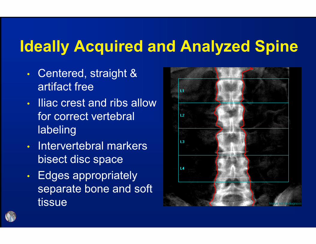
• Centered, straight &
artifact free
• Iliac crest and ribs allow
for correct vertebral
labeling
• Intervertebral markers
bisect disc space
• Edges appropriately
separate bone and soft
tissue
Ideally Acquired and Analyzed Spine

• Green area represents region used to sample soft
tissue
This can increase or decrease measured BMD, in this case
decreased by 0.22
Off-center Anatomy Results in
Inadequate Soft Tissue Sampling
L1-4 BMD = 1.168
L1-4 BMD = 1.146

Demand “Clean” Scans to Eliminate
a Variable when Evaluating
Questionable Results
• It is unknown if artifacts
outside the region of
interest impact BMD results
Do not assume artifacts are
not impacting BMD
The presence of artifact
reduces your certainty that a
BMD change has, or has not
occurred
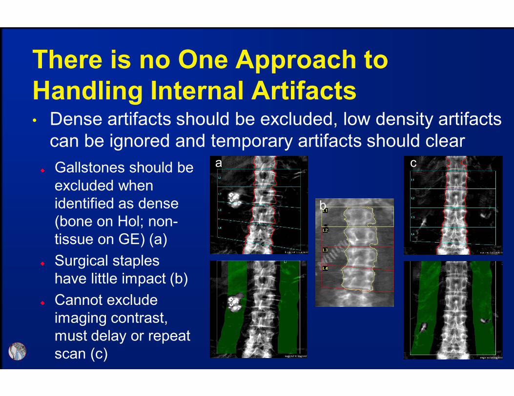
There is no One Approach to
Handling Internal Artifacts• Dense artifacts should be excluded, low density artifacts
can be ignored and temporary artifacts should clear
Gallstones should be
excluded when
identified as dense
(bone on Hol; non-
tissue on GE) (a)
Surgical staples
have little impact (b)
Cannot exclude
imaging contrast,
must delay or repeat
scan (c)
a c
b
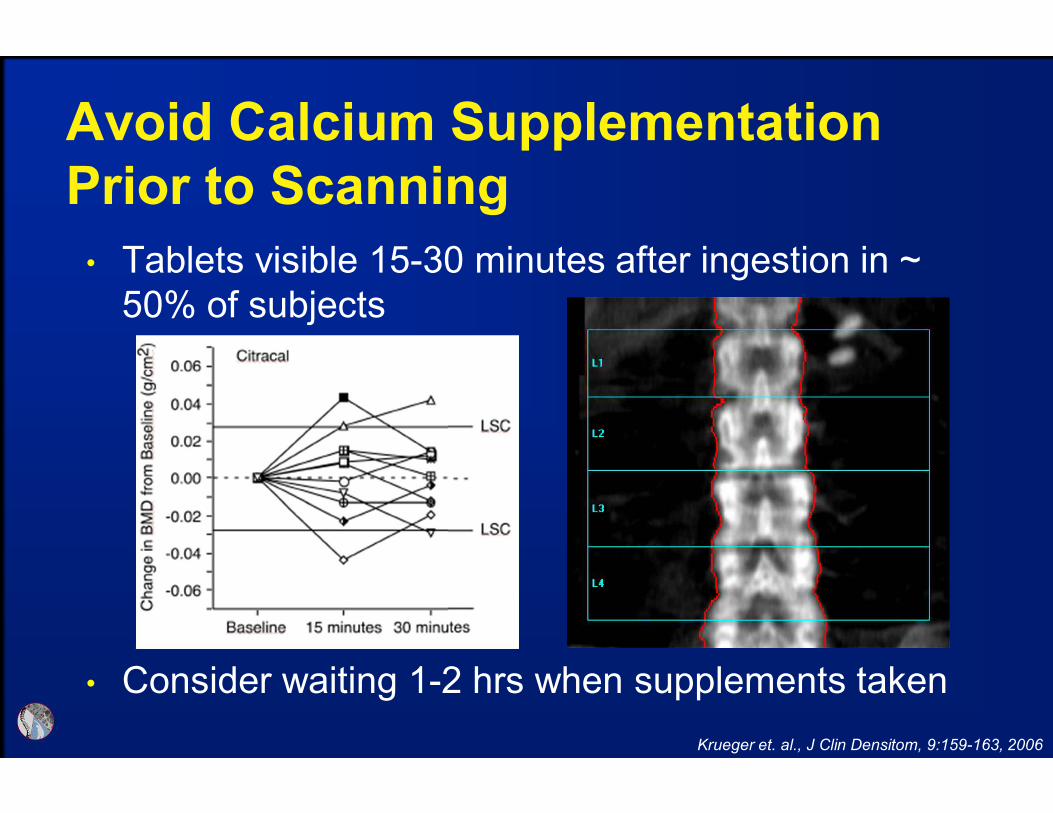
• Tablets visible 15-30 minutes after ingestion in ~
50% of subjects
• Consider waiting 1-2 hrs when supplements taken
Avoid Calcium Supplementation
Prior to Scanning
Krueger et. al., J Clin Densitom, 9:159-163, 2006

Vertebral Labeling Should be Correct
• Each vertebrae is
compared to the labeled
normative database to
generate T-score, when
mislabeled incorrect T-
scores are generated
T-score difference of -0.8
is demonstrated between
correct and incorrect
labeling L1-L4 BMD 0.896 g/cm2
T-score = -2.4(labelling is one off )
L1-L4 BMD 0.798 g/cm2
T-score = -3.2(correct labelling)
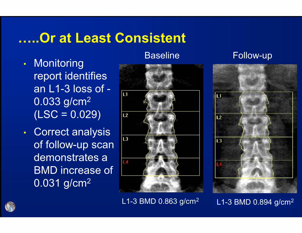
…..Or at Least Consistent
• Monitoring
report identifies
an L1-3 loss of -
0.033 g/cm2
(LSC = 0.029)
Baseline Follow-up
L1-3 BMD 0.863 g/cm2 L1-3 BMD 0.830 g/cm2
• Correct analysis
of follow-up scan
demonstrates a
BMD increase of
0.031 g/cm2
L1-3 BMD 0.894 g/cm2
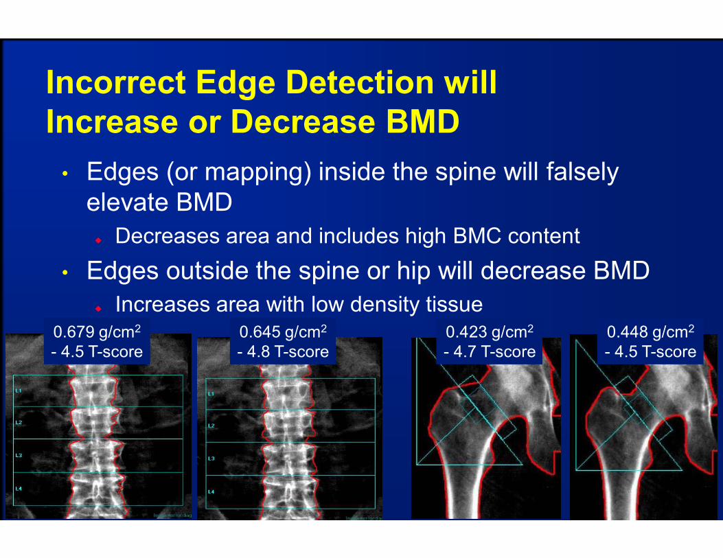
Incorrect Edge Detection will
Increase or Decrease BMD
• Edges (or mapping) inside the spine will falsely
elevate BMD
Decreases area and includes high BMC content
• Edges outside the spine or hip will decrease BMD
Increases area with low density tissue
0.679 g/cm2
- 4.5 T-score
0.645 g/cm2
- 4.8 T-score
0.423 g/cm2
- 4.7 T-score
0.448 g/cm2
- 4.5 T-score
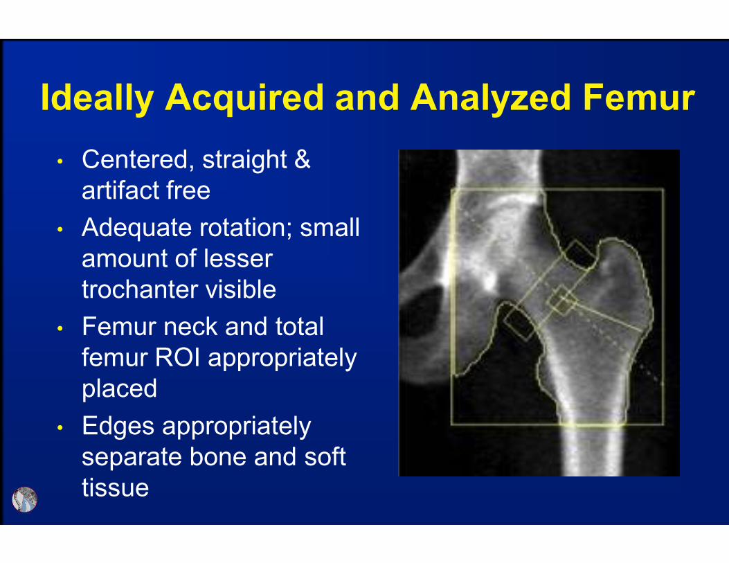
• Centered, straight &
artifact free
• Adequate rotation; small
amount of lesser
trochanter visible
• Femur neck and total
femur ROI appropriately
placed
• Edges appropriately
separate bone and soft
tissue
Ideally Acquired and Analyzed Femur
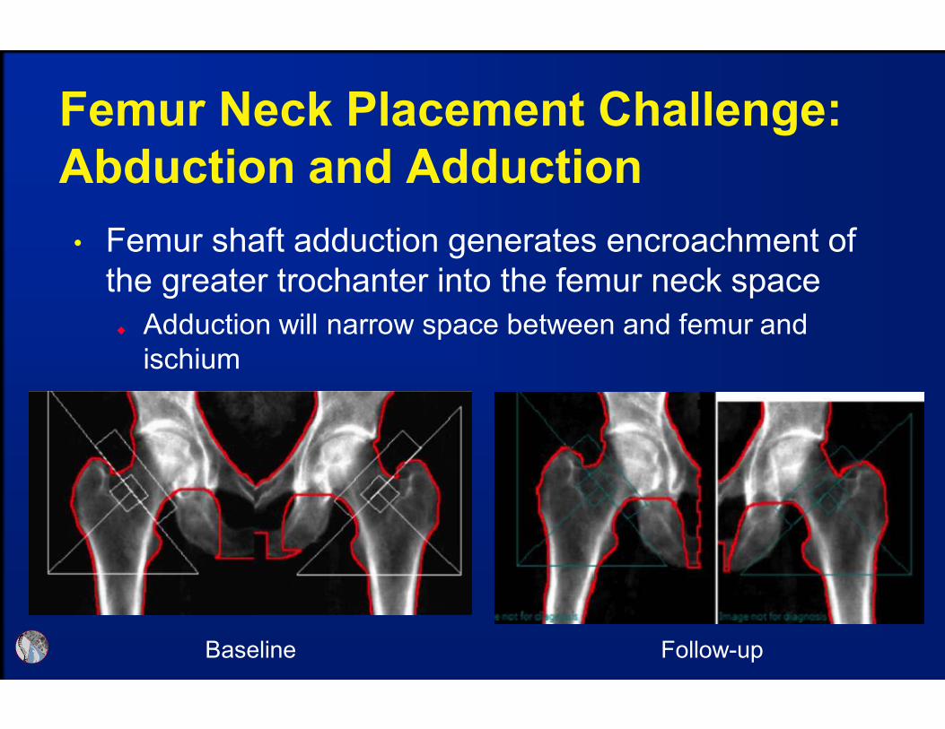
Femur Neck Placement Challenge:
Abduction and Adduction
• Femur shaft adduction generates encroachment of
the greater trochanter into the femur neck space
Adduction will narrow space between and femur and
ischium
Baseline Follow-up

Abduction/Adduction Generally Has
Little BMD Effect, However, Note OutliersData presented for left femoral neck
Ozer, et. al., J Clin Densitom, 13:10-17, 2010
Similar results observed at the total femur
Assume LSC ~0.030
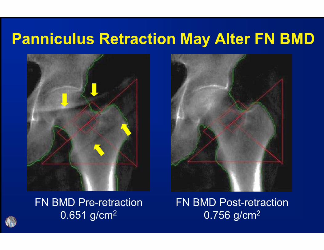
Panniculus Retraction May Alter FN BMD
FN BMD Pre-retraction
0.651 g/cm2
FN BMD Post-retraction
0.756 g/cm2

Panniculus Retraction May
Increase or Decrease Femur BMD
by Amounts > the LSC
Binkley, et. al., J Clin Densitom, 6:199-204, 2003
LSC ~0.048

Panniculus Retraction
Binkley, et. al., J Clin Densitom, 6:199-204, 2003

Femur Neck Placement Challenge:
Rotation Changes Greater Troch
Area• Poor rotation positions the greater trochanter into
femur neck space, increase FN BMD, less impact
on total femur BMD
FN = 1.102 g/cm2
FN area = 5.37 cm2
TF = 1.071 g/cm2
FN = 1.085 g/cm2
FN area = 4.60 cm2
TF = 1.053 g/cm2
FN = 1.068 g/cm2
FN area = 4.40 cm2
TF = 1.092 g/cm2
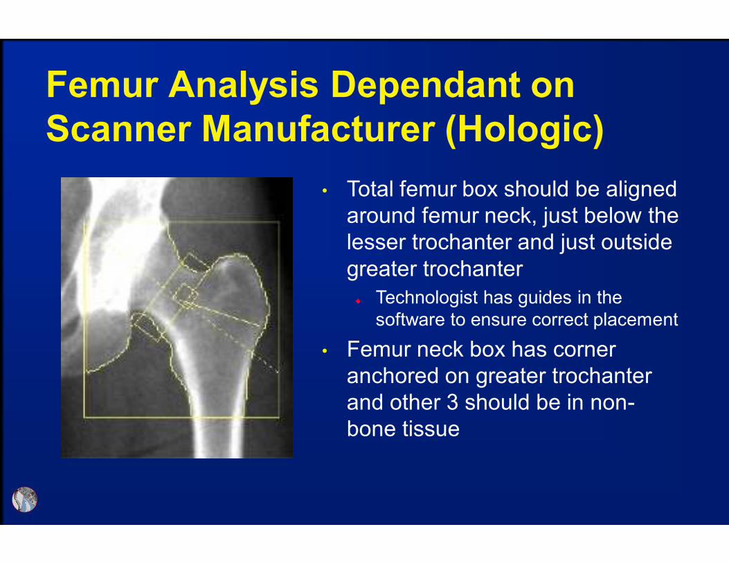
Femur Analysis Dependant on
Scanner Manufacturer (Hologic)
• Total femur box should be aligned
around femur neck, just below the
lesser trochanter and just outside
greater trochanter
Technologist has guides in the
software to ensure correct placement
• Femur neck box has corner
anchored on greater trochanter
and other 3 should be in non-
bone tissue

Femur Analysis Dependant on
Scanner Manufacturer (GE-Lunar)
• Total femur is automatically
determined based on femur neck
box placement
• Femur neck box is placed by
software using “search” option,
determines narrowed area of
neck and lowest BMD
Very large wards area (small square)
indicates search or copy feature
were not used
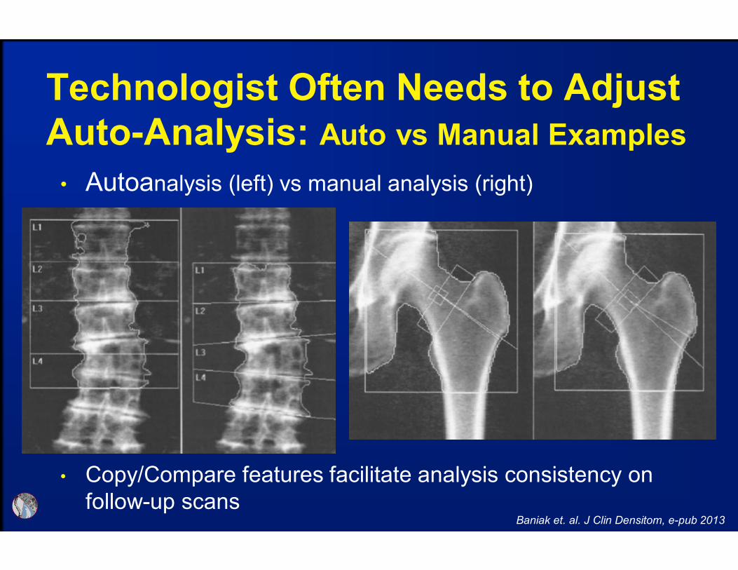
Technologist Often Needs to Adjust
Auto-Analysis: Auto vs Manual Examples
Baniak et. al. J Clin Densitom, e-pub 2013
• Autoanalysis (left) vs manual analysis (right)
• Copy/Compare features facilitate analysis consistency on
follow-up scans

Examples and Tips

GE Scan Modes Should be Based on
Patient Size (Thin, Standard, Thick)
• Software auto-selects
scan mode based on
patient height and
weight
• Sometimes does not
select “thin” when
appropriate – resultant
images on left
• When image is very
“grainy” switch to thick

GE Lunar BMD in g/cm2 is ~10% Higher than HologicSame Patient Scanned on the Same Day
GE Lunar Hologic
L1-L4 BMD 0.889 g/cm2
T-score = -2.4L1-L4 BMD 0.758 g/cm2
T-score = -2.6
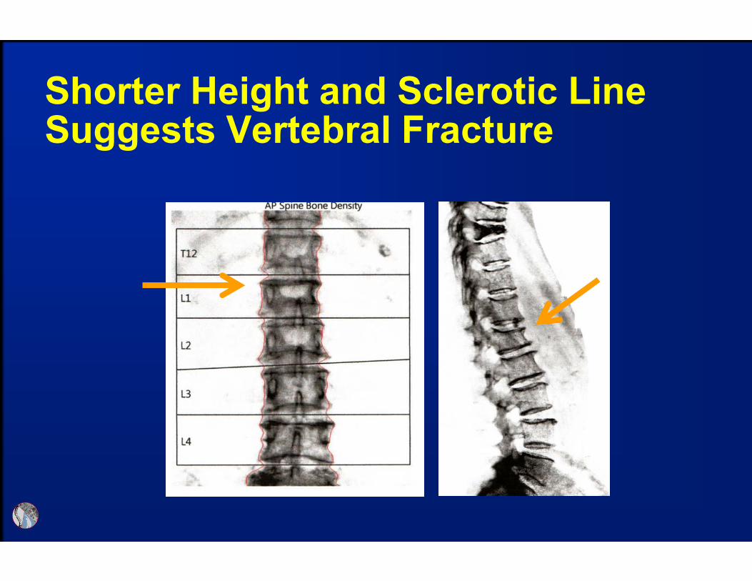
Shorter Height and Sclerotic Line Suggests Vertebral Fracture

Vertebral Bodies with Falsely Elevated BMD Due to Arthritis or Fracture Should be Excluded From Analysis
Arthritis excluded with GE software, printed, but excluded from calculations
Fracture excluded with Hologic software (L1), data removed from report
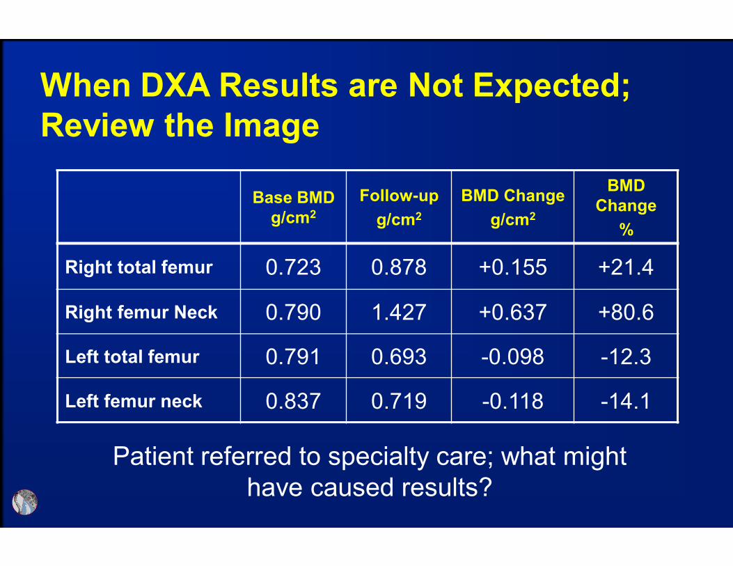
Base BMD
g/cm2
Follow-up
g/cm2
BMD Change
g/cm2
BMD
Change
%
Right total femur 0.723 0.878 +0.155 +21.4
Right femur Neck 0.790 1.427 +0.637 +80.6
Left total femur 0.791 0.693 -0.098 -12.3
Left femur neck 0.837 0.719 -0.118 -14.1
When DXA Results are Not Expected;
Review the Image
Patient referred to specialty care; what might
have caused results?

Evaluating the Images Clearly Disclose
Cause for Unusual Results
Baseline
Follow-up
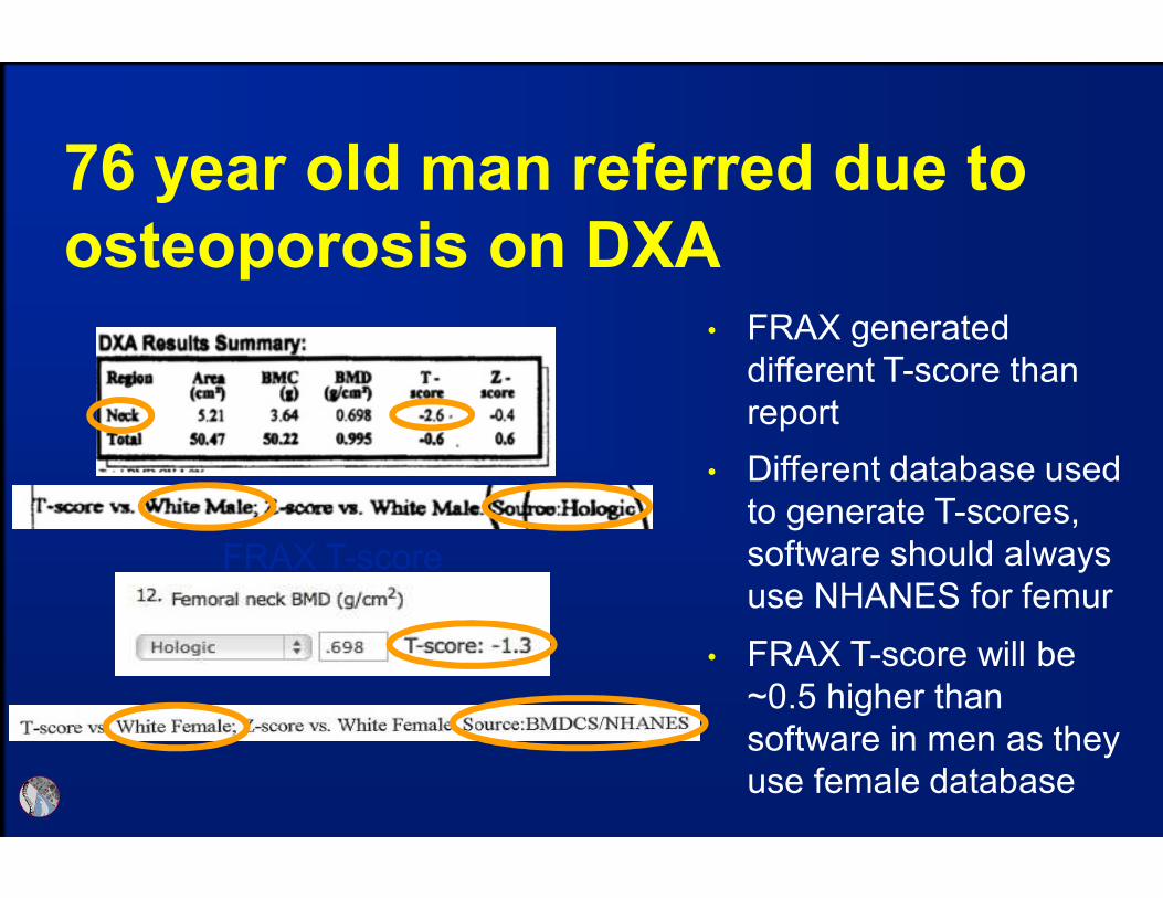
76 year old man referred due to
osteoporosis on DXA
FRAX T-score
• FRAX generated
different T-score than
report
• Different database used
to generate T-scores,
software should always
use NHANES for femur
• FRAX T-score will be
~0.5 higher than
software in men as they
use female database

55 year old female with congenital hip
dysplasia; screening DXA resulted in
referral for teriparatide consideration
Read the fine print: low percent fat in first scan suggests
instrument error

Image Can Suggest When Scanner
Needs Service
• Example of detector
failure on GE instrument

Positioner Slot
Correct Wrist
Location
Tissue-Typing Error Due to PositionerGE-Lunar
• If open area of the strap slots
are at the start or end of
scan field, tissue typing may
be incorrect and falsely
elevate 1/3 radius BMD
• Bone edges are usually
correct, requiring evaluation
of tissue
• Most common when
positioner is used backwards
Krueger et. al. J Clin Densitom, 2012 e-pub

• The software may include clothing in soft-tissue assessment and cause error in BMD calculation; this might be an issue with other manufacturers (has not been reported)
• These errors, in many cases are likely greater than the LSC
Clothing
Clothing on Forearm Can Cause
Tissue-Typing Errors that Affect BMD GE-Lunar
Krueger et. al. J Clin Densitom, 2012 e-pub

These errors result in measurement error greater than the LSC
Tissue-Typing Errors Impact on
Radius BMD GE-Lunar
Krueger et. al. J Clin Densitom, 2012 e-pub
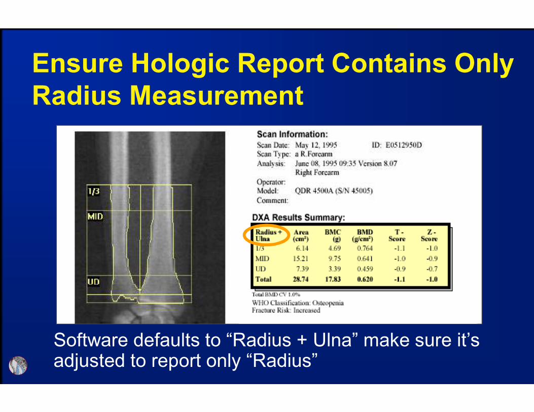
Software defaults to “Radius + Ulna” make sure it’s adjusted to report only “Radius”
Ensure Hologic Report Contains Only
Radius Measurement

Use Report to Identify Instrument and
Database Used: Hologic

Use Report to Identify Instrument and
Database Used: GE

DXA Troubleshooting when
Observing Unexpected Results
• Categories to investigate potential sources for error:
items related to the
Technologist – acquisition and analysis
Equipment – software and hardware
Patient – recent examinations and medical history

ISCD-10 Coding

Implementation Date is No
Longer Oct. 2014
http://www.cms.gov/Medicare/Coding/ICD10/index.html?redirect=/icd10

ICD-10 Summary
• Developed by WHO to replace ICD-9 which was
out of digits for more codes
• ICD-10 provides a more defined diagnosis
Allows more detailed documentation; specify site and
laterality
• Will not effect CPT® codes for outpatient coding
• All CPT® codes submitted to payers must be
supported by the MR and reported with the
appropriate ICD-10 code
• Affects all medical personal and support staff
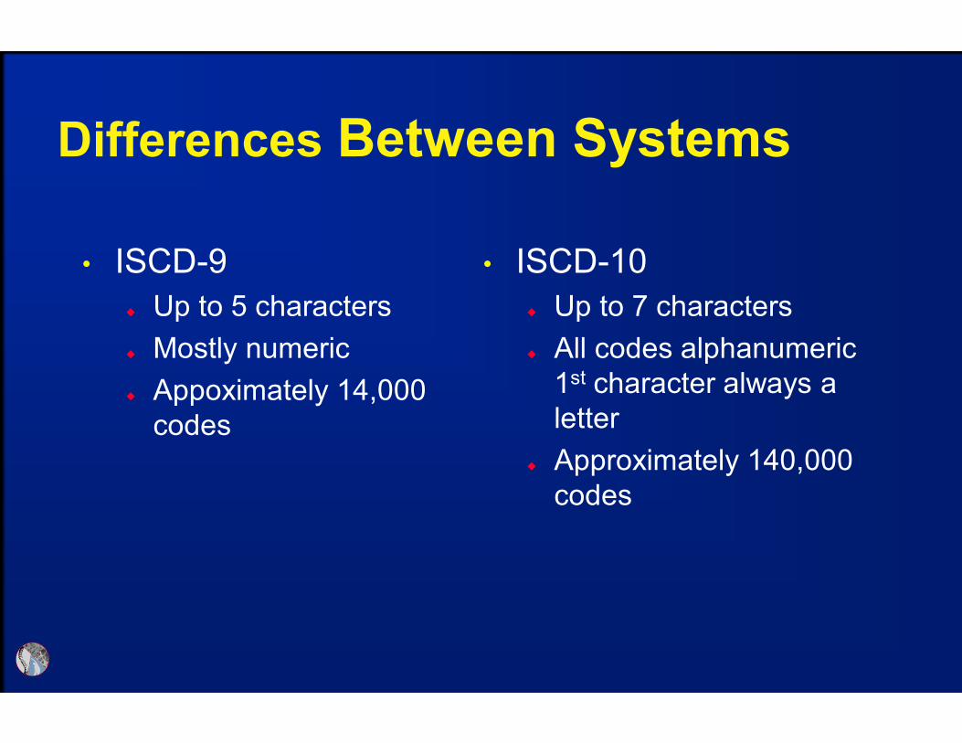
Differences Between Systems
• ISCD-9
Up to 5 characters
Mostly numeric
Appoximately 14,000
codes
• ISCD-10
Up to 7 characters
All codes alphanumeric
1st character always a
letter
Approximately 140,000
codes

Validate Transition Plan is
Executed Appropriately
• Implementation errors will result in:
Claim rejections
Denials
Delays
Incorrect decisions based on diagnosis data

Considerations for Transition Plan
• Discuss implementation plans for your practice
with payers, determine how/if ICD-10 might affect
contracts
• Identify required changes to work and business
practices
Staff training needs (both clinical and non-clinical)
• Budget for time and costs pertaining to
implementation

Tools for Transition
• General reference and preparation
CMS website –http://www.cms.gov/Medicare/Coding/ICD10/index.html?redirect=/ic
d10
AACE courses and on-line material to members
• Assistance with ICD-10 Code Identification
ICD-9 to ICD-10 Code Translator
o Lists new codes for known ICD-9 code
o http://www.aapc.com/icd-10/codes/
Crosswalk Help
o Allows you to find new or unknown codes by category
o http://www.aapc.com/icd-10/crosswalks/
International Society for Clinical
Densitometry (ISCD)
• Mission: To Advance Excellence in the Assessment
of Skeletal Health
Promoting education and a broad understanding of bone
mass measurement and skeletal health assessment
technologies
Assuring proficiency and quality in skeletal health
assessment through certification and accreditation
Promoting appropriate patient access to bone mass
measurement and skeletal health assessment technologies
Supporting advances in osteoporosis diagnosis and
treatment

ISCD Certification & Accreditation
• Clinicians (CCD) and Technologists (CBDT)
CBDT is NCAA accredited and CCD application being
submitted this fall
• Transitioning to Maintenance of Certification (2015)
Annual fee includes access to on-line CME/CE and
tracking of credits accumulated through ISCD
ISCD Membership includes Maintenance of Certification
at no additional cost.
• Facility Accreditation Program streamlined to focus on core
elements

ISCD Education
• Osteoporosis Essentials Course
Bone Densitometry Course updated with international
content and being offered jointly with IOF
• Annual Meetings
2014 held jointly with IOF
2015 in Chicago includes Position Development sessions
2016 in Gallway Ireland – first international meeting in
over 15 years
• Position Development Conference Non-BMD DXA fracture risk prediction tools (TBS/HSA) Central CT measures of fracture risk
o Prevalent fracture identification/Fracture risk predictiono Opportunistic screening from clinical CT scans

ISCD Education
• Online Learning
Offerings for Clinician (ACCME Category 1) and
Technologists (ASRT Category A)
Access included with Membership, nominal fee for non-
members.
• Vertebral Fracture Recognition
Course redesigned to focus on DXA and other modalities
for recognition
• Fracture Liaison Services Creating educational materials to provide education
outlined in a needs assessment.
ISCD Future Activities
• Continuing US and International partnerships to
better impact the field
Promote access to skeletal health measurement through
DXA Alliance and collaboration with other professional
organizations
Joint educational activities with International Osteoporosis
Foundation (IOF) and other professional societies National Bone Health Alliance
o Promote bone health and prevent disease; improve diagnosis and treatment of bone disease; and enhance bone research, surveillance and evaluation.
US Bone and Joint Initiativeo Fit to a T (Know your T-score)