dyna-litedynalite.com/wp-content/uploads/2015/06/mp-instruction-manual.pdf · general instructions...
TRANSCRIPT

power pack instruction manual
Dyna-Lite

Dyna-Lite: The Legacy of Lighting We thank you for choosing state-of-the-art Dyna-Lite studio lighting equipment. Since 1970 Dyna-Lite has
been committed to the design and manufacture of small, lightweight power packs to help professional
photographers improve their control over the challenges of lighting. Our products are designed to make it
easier for you to brilliantly light people or products, in the studio or on location. We pride ourselves in
making an excellent product that keeps up with the ever changing needs of the professional photographer
such as the two stop Variator for the ultimate in flash control and MP/SP packs featuring the Pocketwizard
radio receiver already built in.
Lighter Weight means less to carry or ship. Yet we pack more watts per pound into our power units
than any other power pack on the market.
Compact Size and smaller footprint, makes for power packs that take up less room in the studio, on
location, or in a shipping case.
Extended Life of Dyna-Lite power packs insure a longer continuous duty life cycle and more
“stamina” than competitive systems.
Flexibility and Control built into sensibly priced Dyna-Lite power packs simplify complex lighting set-ups.
Abuse Resistant Design through the use of arc proof connectors and switches make Dyna-Lite
equipment safe and virtually “assistant proof.”
Reliability engineered into every Dyna-Lite power pack, durable and consistent Dyna-Lite Power
Packs are the choice of professional photographers and equipment rental houses worldwide.
Two year Warranty comes standard with all Dyna-Lite power packs. Be sure to return the enclosed warranty
card so that we may register you in the growing family of Dyna-Lite power pack owners. Quick turn-around
repair service, should you ever need it, is available at Dyna-Lite headquarters in Union, New Jersey, and at
conveniently located regional service centers. In addition, factory-trained service capability exists at many
Dyna-Lite dealer locations.
If you have any questions about your Dyna-Lite power pack, please call 1-800-722-6638. We are here to help.
.

Important Safeguards When using this flash equipment, basic safety precautions should always be followed, included the following:
1. Read and understand ALL instructions and specifications before using your Dyna-Lite equipment.
2. Care must be taken when handling the flash heads as injury could occur from touching the
modeling lamp(s) or flash tube(s).
3. DO NOT operate a power pack or flash head with a damaged cord or if the unit has been dropped.
4. If an extension power cord is necessary, a cord with a suitable current rating should be used. Cords
rated for less than 15 amps may overheat. Care should be taken to arrange the cord so that it will not
be tripped over or pulled from the electric source outlet.
5. Unplug the power pack from the electrical outlet when not in use. NEVER yank the cord to pull
the plug from the outlet.
6. Let flash heads cool completely before putting them away. Loop flash cables in an 8” to 10”
diameter when storing.
7. DO NOT allow power cord(s) or flash head cable(s) to hang on or touch hot surfaces.
8. To avoid electrical shock hazard, DO NOT attempt to disassemble the power pack. Incorrect reassembly
could cause an electrical shock hazard when a power pack is subsequently used. Take it to a qualified
Dyna-Lite service technician when repair is required.
9. When the power pack is not in use for one month or more, it is wise to periodically plug the
power pack in and turn it ON for a couple of hours. It is not necessary to operate a flash head
during this “idling” time.
10. Use the flash head extension cable locking rings with the flash head pigtail not at power pack.
11. The use of properly GROUNDED AC outlet is recommended.
12. Remove plastic or metal flash head cover before shooting.
13. Please set the sync mode switch to the “SYNC” position before turning the power and model
lamp switches “ON” and “OFF”. This procedure will ensure the longevity of the power and
modeling lamp switches.
Personal Records/Insurance
Date of Purchase ___________________________ Serial Number _______________
Dealer Name ____________________________ Phone _____________________
Address _____________________________
Insurance Company _________________________ Policy Number _______________

General Instructions for all power packs
The following instructions are applicable to all Dyna-Lite power packs except as noted. Additional features
specific to individual packs are described on the pages that follow.
Flash Heads To plug in flash heads, first plug the flash head extension cable into flash head pigtail, then plug the other end into a
Flash Head Outlet (this can be done at anytime without shutting down the power pack since outlets are arc protected). Align the
white dot on the extension cable plug with the back of the pack.
AC Power First plug the AC power cord into the power pack, then into a grounded AC outlet. Next, turn AC Power Switch on. Then, wait for
the ready light or audible beep before firing flash. The Ready Light Switch also serves as an open flash test switch and signals
100% flash readiness. NOTE: The Audible Ready Indicator indicates 100% flash readiness and can be turned on or off.
Modeling Lamps Turn Modeling Light Switch on. Make sure modeling light switch on back of flash head is turned on. All power packs have
individually operated modeling light switches that can be used to control the brightness on the modeling lamp to match the
relative intensity of the flash.
Flash Head Power Power Control Switches can be adjusted to provide full, half or quarter power to the flash head outlets in the
respective “A” or “B” channels.
Ratio/Combined Switch All Dyna-Lite power packs feature the Ratio/ Combined switch. On all packs the flash head outlets are grouped into two separate
channels (sometimes called banks) marked “A” and “B”. The switch has two options; the first is A:B and the second is A+B.
Ratio A:B (Asymmetrical Power) Uneven distribution of power to the A and B channels is referred to as asymmetrical or ratio and allows more control of light out-
put by dividing the pack into two halves or channels that can each be separately controlled over a three stop range. First make
sure that you have the Ratio/Combined switch set to A:B. Now the corresponding Power Control switches control each channel
individually. If you plug one head into the Channel A side, that Power Control regulates only that same side. The Channel B side is
dormant until you plug a head into an outlet on the “B” side. Consequently, the Power Control switch on the B side only controls
Channel B. As you plug in an additional head to either (or both) sides, the power is equally split, but only among each channel. If
you had one flash head in Channel A set at 100 watt/seconds and two heads in Channel B set at 100 watt/seconds, the A head
would deliver 100 watt/seconds of power and each of the B heads would deliver 50 watt/second each.
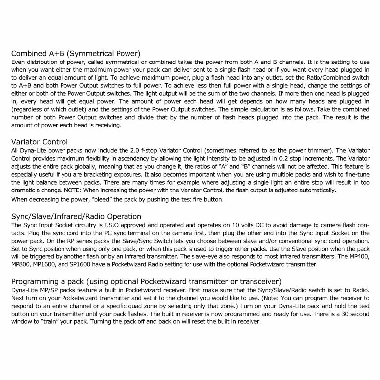
Combined A+B (Symmetrical Power) Even distribution of power, called symmetrical or combined takes the power from both A and B channels. It is the setting to use
when you want either the maximum power your pack can deliver sent to a single flash head or if you want every head plugged in
to deliver an equal amount of light. To achieve maximum power, plug a flash head into any outlet, set the Ratio/Combined switch
to A+B and both Power Output switches to full power. To achieve less then full power with a single head, change the settings of
either or both of the Power Output switches. The light output will be the sum of the two channels. If more then one head is plugged
in, every head will get equal power. The amount of power each head will get depends on how many heads are plugged in
(regardless of which outlet) and the settings of the Power Output switches. The simple calculation is as follows. Take the combined
number of both Power Output switches and divide that by the number of flash heads plugged into the pack. The result is the
amount of power each head is receiving.
Variator Control All Dyna-Lite power packs now include the 2.0 f-stop Variator Control (sometimes referred to as the power trimmer). The Variator
Control provides maximum flexibility in ascendancy by allowing the light intensity to be adjusted in 0.2 stop increments. The Variator
adjusts the entire pack globally, meaning that as you change it, the ratios of “A” and “B” channels will not be affected. This feature is
especially useful if you are bracketing exposures. It also becomes important when you are using multiple packs and wish to fine-tune
the light balance between packs. There are many times for example where adjusting a single light an entire stop will result in too
dramatic a change. NOTE: When increasing the power with the Variator Control, the flash output is adjusted automatically.
When decreasing the power, “bleed” the pack by pushing the test fire button.
Sync/Slave/Infrared/Radio Operation The Sync Input Socket circuitry is I.S.O approved and operated and operates on 10 volts DC to avoid damage to camera flash con-
tacts. Plug the sync cord into the PC sync terminal on the camera first, then plug the other end into the Sync Input Socket on the
power pack. On the RP series packs the Slave/Sync Switch lets you choose between slave and/or conventional sync cord operation.
Set to Sync position when using only one pack, or when this pack is used to trigger other packs. Use the Slave position when the pack
will be triggered by another flash or by an infrared transmitter. The slave-eye also responds to most infrared transmitters. The MP400,
MP800, MP1600, and SP1600 have a Pocketwizard Radio setting for use with the optional Pocketwizard transmitter.
Programming a pack (using optional Pocketwizard transmitter or transceiver) Dyna-Lite MP/SP packs feature a built in Pocketwizard receiver. First make sure that the Sync/Slave/Radio switch is set to Radio.
Next turn on your Pocketwizard transmitter and set it to the channel you would like to use. (Note: You can program the receiver to
respond to an entire channel or a specific quad zone by selecting only that zone.) Turn on your Dyna-Lite pack and hold the test
button on your transmitter until your pack flashes. The built in receiver is now programmed and ready for use. There is a 30 second
window to “train” your pack. Turning the pack off and back on will reset the built in receiver.

MP400/MP800
MP1600/SP16
Power Packs 1. AC On / Off Power Switch - Turns power
pack on and off.
2. Two stop Variator Conrol - Fine-tune your
power settings in 0.2 stop detented incre-
ments. Used in combinations, the power
control switches and Variator provide a total
of 18 different power settings with a single
flash head, going as low as 15 watt/
seconds.
3. Power Control Switches – Three position
full/half/quarter power switches provide
power settings over a three stop range per
channel. (These can be trimmed using the
Variator or combined using the Ratio output
switch.)
4. Proportional Modeling Light Controls-Five
position proportional modeling light switch
allows you to control the ratio of your
modeling light for pre-visualization. Flash
head fans always run at full speed re-
gardless of switch position.
5. Flash Head Outlets – The pack is capable of
accepting up to four heads and each is outlet
is arc protected. This means that it is
completely safe
to plug and unplug flash head cables into the outlets even while the pack is on.
6. Modeling Light Delay Circuit - (SP1600 only) Delays the modeling light from coming back on after flash for 1, 2, 4 or 8 seconds. It
is especially useful when you are dragging the shutter so the modeling lights will not effect exposure. It also redirects the power
from the pack when recycling as the modeling lights draw an additional 2 amps of power each.
7. AC Power Cord Socket and Circuit Breaker - Offers easily reset-able protection.
8. Ratio/Combined Output Switch - An indicator light tells you whether your power is routed symmetrically or asymmetrically
between the “A” and “B” flash head outlet banks.
9. Ready Light/Test Switch - When lit the pack is fully charged. This button can also be used to manually trigger the pack.
10. Sync, WEIN slave-eye and Pocketwizard selector switch - Can be triggered by sync cord, any flash and will also respond to
most infrared triggers or optional Pocketwizard radio slave.
11. Audible Ready Indicator Switch- Get audible confirmation that the pack is fully recycled to full power.
5.
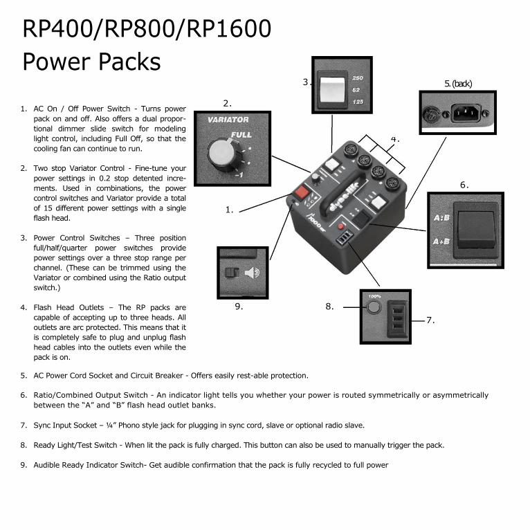
RP400/RP800/RP1600
Power Packs 3.
1. AC On / Off Power Switch - Turns power
pack on and off. Also offers a dual propor-
tional dimmer slide switch for modeling
light control, including Full Off, so that the
cooling fan can continue to run.
2. Two stop Variator Control - Fine-tune your
power settings in 0.2 stop detented incre-
ments. Used in combinations, the power
control switches and Variator provide a total
of 15 different power settings with a single
flash head.
3. Power Control Switches – Three position
full/half/quarter power switches provide
power settings over a three stop range per
channel. (These can be trimmed using the
Variator or combined using the Ratio output
switch.)
4. Flash Head Outlets – The RP packs are
capable of accepting up to three heads. All
outlets are arc protected. This means that it
is completely safe to plug and unplug flash
head cables into the outlets even while the
pack is on.
5. AC Power Cord Socket and Circuit Breaker - Offers easily rest-able protection.
6. Ratio/Combined Output Switch - An indicator light tells you whether your power is routed symmetrically or asymmetrically
between the “A” and “B” flash head outlet banks.
7. Sync Input Socket – ¼” Phono style jack for plugging in sync cord, slave or optional radio slave.
8. Ready Light/Test Switch - When lit the pack is fully charged. This button can also be used to manually trigger the pack.
9. Audible Ready Indicator Switch- Get audible confirmation that the pack is fully recycled to full power
5. (back)
2.
4.
6.
1.
9. 8.
7.
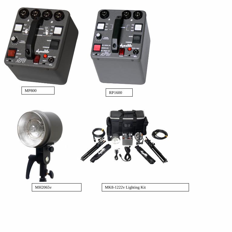
MH2065v
MP800 RP1600
MK8-1222v Lighting Kit

Getting Started with Basic Lighting Light Meters
It is recommended that you purchase a flash meter. This device measures the amount of light coming from
your flash system. This light can vary depending on the distance of the light from the subject and various light
modifiers, which are used to change the quality of the light. Flash meters are available from manufactures such
as Sekonic, which features PocketWizard technology in select models. Most flash meters are incident flash
meters, meaning you take the meter and point it back towards the camera from the perspective of the subject
to maintain an accurate reading of light falling upon the subject. You may also wish to point your meter at the
direction of the light source from the position of the subject when you are using multiple lights to understand
the ratios between the lights. Some meters are reflective meters (often referred to as spot meters) and
measure the light being reflected back from the subject taken from the camera position.
Halving and Doubling
Photography is based on the principle of halving and doubling. Shutter speeds are expressed this was as well
as the amount of light between f-stops. Your flash unit works based on the same principle. That is why the
units are expressed in terms of this numerology. Consequently, 250 watt/seconds will deliver twice as much
light as 125 watt/seconds and the relationship between these settings is one stop. Another thing to consider is
the inverse square law. As you double the distance between the light and the subject, you loose two f-stops of
illumination. (See inverse square law diagram.) Keep in mind the actual f-stop values vary depending on the
actual power of the light source.

Sample lighting setups Basic single light
There is an amazing amount of versatility that you can get out of one light. Consider for a moment that the sun is only one
source, however the angle of the light (ie time of day, atmosphere it passes through and location in the world) affects the quality.
In addition there are surfaces that are reflecting, modifying and diffusing light all the time.
Using a simple umbrella for example, diffuses the light and creates a larger and softer, broader source, then using the strobe by
itself. The closer you make the source the more specular or harder the light appears (fig.1) and the further the source the flatter
or softer that the light appears. (fig. 2)
The first thing you want to do is position the umbrella in the light to the point just before there is no spillage outside the
umbrella’s interior surface. If you place the light too close to the umbrella, you are not taking advantage of the broad source your
umbrella offers. Next, position the umbrella off to one side of your subject to create dimension. (fig. 1-A) Start at three or four
feet away for a basic head and shoulders portrait and slightly above the subject pointing slightly down. (fig. 2-A) Experiment with
the angle relationship to your subject.
It is best to do this in a dark room with the modeling light on to watch how the light falls on your subject. Keep in mind that the
closer your subject is to the background and the further the light is to the subject the more illumination of the background will
occur. (Also by using a darker back ground, more light will be needed to illuminate it.) To create separation from the background
use a second light either illuminating the background or as a hair light to illuminate the back of the subject.
figure 1 figure 2
©Andre
Cos
tantin
i
figure 1-A
figure 2-A
©Andre
Cos
tantin
i
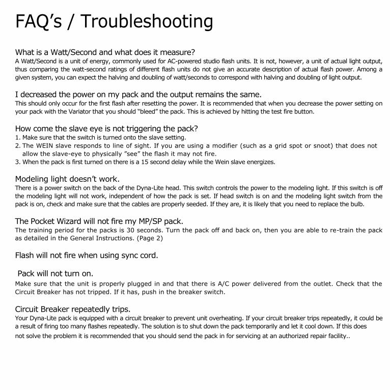
FAQ’s / Troubleshooting
What is a Watt/Second and what does it measure? A Watt/Second is a unit of energy, commonly used for AC-powered studio flash units. It is not, however, a unit of actual light output,
thus comparing the watt-second ratings of different flash units do not give an accurate description of actual flash power. Among a
given system, you can expect the halving and doubling of watt/seconds to correspond with halving and doubling of light output.
I decreased the power on my pack and the output remains the same. This should only occur for the first flash after resetting the power. It is recommended that when you decrease the power setting on
your pack with the Variator that you should “bleed” the pack. This is achieved by hitting the test fire button.
How come the slave eye is not triggering the pack? 1. Make sure that the switch is turned onto the slave setting.
2. The WEIN slave responds to line of sight. If you are using a modifier (such as a grid spot or snoot) that does not
allow the slave-eye to physically ”see” the flash it may not fire.
3. When the pack is first turned on there is a 15 second delay while the Wein slave energizes.
Modeling light doesn’t work. There is a power switch on the back of the Dyna-Lite head. This switch controls the power to the modeling light. If this switch is off
the modeling light will not work, independent of how the pack is set. If head switch is on and the modeling light switch from the
pack is on, check and make sure that the cables are properly seeded. If they are, it is likely that you need to replace the bulb.
The Pocket Wizard will not fire my MP/SP pack. The training period for the packs is 30 seconds. Turn the pack off and back on, then you are able to re-train the pack
as detailed in the General Instructions. (Page 2)
Flash will not fire when using sync cord.
Pack will not turn on.
Make sure that the unit is properly plugged in and that there is A/C power delivered from the outlet. Check that the
Circuit Breaker has not tripped. If it has, push in the breaker switch.
Circuit Breaker repeatedly trips. Your Dyna-Lite pack is equipped with a circuit breaker to prevent unit overheating. If your circuit breaker trips repeatedly, it could be
a result of firing too many flashes repeatedly. The solution is to shut down the pack temporarily and let it cool down. If this does
not solve the problem it is recommended that you should send the pack in for servicing at an authorized repair facility..

Specifications MP/RP400 MP/RP800 MP/RP1600 AP1600 SP1600
Power- Wall/Seconds 400 800 1600 1600
1600 Recycle Time -
Full Power in seconds 1.0 1.2 2.3 1.2 1.2
Draw 7 14 14 18 18
Flash consistency • F • stop 1/10 1/10 1/10 1/10 1/10 Flash Duration • seconds Maximum
(two heads min power)
(one head, max power)
1/4500
1/1000
1/4500
1/700
00
1/3000
1/350
1/4200
1/1000
1/4200
1/1000
Sync Voltage 10 10 10 10 10
F- slop Range 6 6 6 6 6
Vanator Range (in 0.2 stop adjustments) 2 2 2 2 2
Built in WEIN slave yes yes yes no yes
es POCKETWIZARD receiver yes/no Yes/no Yes/no no yes
Maximum heads allowed 4/3 4/3 4/3 3 4
Dimensions 5 7/8 x 6 7/8 5 7/8'x 6 7/8 5 7/8' x 6 7/8 .5 716' x 6718' 71/EV x 9 114'
149mm x 175 mm 149 mm x 175mm 149 mm x 175mm 149fern x 235mm 1 el elm x 235 mm
Height
(including handle) 5 1/4" 5 3/4" 7 3/4” 8 " 8 "
133mm 146mm 197mm 203 mm 203 mm
Weight 4.3 lb 5.4 lb 7.2 lb 12.0 lb 12.1 lb
DynaLite Inc., 1050 Commerce Ave. Union, NJ 07083 800.722.6638 www.dynalite.com
110'