dynalight: a dynamic visible light communication link for
TRANSCRIPT

Delft University of TechnologyMaster’s Thesis in Embedded Systems
DynaLight: A Dynamic Visible LightCommunication Link for Smartphones
Michail Vasilakis

DynaLight: A Dynamic Visible Light
Communication Link for Smartphones
Master’s Thesis in Embedded Systems
Embedded Software SectionFaculty of Electrical Engineering, Mathematics and Computer Science
Delft University of TechnologyMekelweg 4, 2628 CD Delft, The Netherlands
Michail [email protected]
11th December 2015
AuthorMichail Vasilakis ([email protected])
TitleDynaLight: A Dynamic Visible Light Communication Link for Smartphones
MSc presentation18th December 2015
Graduation CommitteeProf. Dr. K.G. Langendoen (chair) Delft University of TechnologyM.A. Zuniga Zamalloa, PhD Delft University of TechnologyDr. Judith Redi Delft University of Technology

Abstract
Nowadays, Visible Light Communication (VLC) has attracted the atten-tion of the scientific community due to its great potential in creating smartcommunication links. Exploiting visible light modulations, could in timeenable Internet connectivity via light lamps. Recent research studies haveshown that modern smartphones have the ability to capture high frequencylight patterns and increase the applicability of VLC links, enabling smartapplications. However, creating flexible camera-based VLC links brings-up several challenges that are introduced by the diversity of the availabledevices.
Firstly, existing VLC systems offer inflexible setups that are designed tooperate at fixed distances. This fact causes problems when it comes to vary-ing the distance between the transmitter and the receiver. This thesis in-troduces DynaLight : an adaptive line-of-sight VLC system for smartphonesthat dynamically adjusts and maximizes its channel capacity by estimatingthe distance between the transmitter and the receiver.
Secondly, the wide diversity in smartphones’ hardware introduces prob-lems when it comes to implementing a generic VLC link for market smart-phones. In order to increase the applicability of our system, we chose toutilize inexpensive hardware, that introduce performance limitations, suchas limited camera control. We present an image processing pipeline thatidentifies and overcomes effects that are caused by off-the-shelf hardware,and we further increase the amount of information, that can be extracted,by 40%.
Last but not least, we develop a smartphone application that implementsour enhancements and draws attention to synchronization challenges. Ourconclusions indicate that the applicability of smartphone VLC links will befurther extended due to the rapid evolution of modern smartphones.

iv

Preface
The current Master thesis concerns the final part of my Master of Sciencein Embedded Systems at Delft University of Technology. I had always beenpassionate about smartphones and their capabilities to improve our every-day lives. During the first year of my master studies, I had the chanceto participate in the Smart Phone Sensing course offered by the EmbeddedSoftware group in TU Delft. This is when I realized my interest in smarphonesensing, as well as in its potential to change people’s lives. I was thrilledwhen I first read a paper on Visible Light Communication and realized thatthis was the topic that I wanted to master. Furthermore, it is a field thatcombines communication theory along with optics, smartphone sensing andimage processing which makes it challenging to work on. During these eightmonths I was exposed to scientific fields that I had no previous experienceand had the opportunity to remarkably improve my scientific skills.
I would like to express my deepest gratitude to my supervisor, Marco Zuniga,for giving me the opportunity to work on this project. During our meetingshe showed me not only how to do research and have a critical thinking, butalso how to be confident and manage my stress. With his knowledge andexperience he helped me improve my writing and presentation skills. Next,I would like to thank Ioannis Protonotarios for assisting me with all thehardware related issues and for being so patient with me. Many thanks alsogo out to all my fellow colleagues Marco, Dimitris, Platon, Roshan, Coenand people from“The 9th Floor” for their ideas and feedback. I would alsolike to thank Katerina and Andri for their valuable comments and supportin improving the current report.
Last but not least, I would like to thank my family and especially myparents for their unselfish love and support throughout my entire life.
Michail Vasilakis
Delft, The Netherlands11th December 2015
v

vi

Contents
Preface v
1 Introduction 1
1.1 Motivation . . . . . . . . . . . . . . . . . . . . . . . . . . . . 2
1.2 Contributions . . . . . . . . . . . . . . . . . . . . . . . . . . . 3
1.3 Thesis Organization . . . . . . . . . . . . . . . . . . . . . . . 3
2 Background 5
2.1 Transmitter-Receiver Alternatives . . . . . . . . . . . . . . . 5
2.2 Rolling Shutter . . . . . . . . . . . . . . . . . . . . . . . . . . 6
2.3 DynaLight’s Requirements . . . . . . . . . . . . . . . . . . . . 8
3 Related Work 11
3.1 VLC projects using LEDs or Photodiodes . . . . . . . . . . . 11
3.2 Camera-based VLC . . . . . . . . . . . . . . . . . . . . . . . . 11
3.2.1 LED to Camera Communication . . . . . . . . . . . . 12
3.2.2 Screen to Camera Communication . . . . . . . . . . . 14
3.2.3 Indoor Localization . . . . . . . . . . . . . . . . . . . . 15
3.2.4 Summary . . . . . . . . . . . . . . . . . . . . . . . . . 17
4 Overview 19
4.1 System Components . . . . . . . . . . . . . . . . . . . . . . . 19
4.2 Basic Functionalities . . . . . . . . . . . . . . . . . . . . . . . 20
5 Transmitter 23
5.1 Modulation Technique . . . . . . . . . . . . . . . . . . . . . . 23
5.2 Packet Structure and Encoding . . . . . . . . . . . . . . . . . 24
5.3 Implementation Details . . . . . . . . . . . . . . . . . . . . . 24
6 Receiver 27
6.1 Camera Control . . . . . . . . . . . . . . . . . . . . . . . . . . 27
6.2 Image Processing . . . . . . . . . . . . . . . . . . . . . . . . . 29
6.2.1 Transmitter Detection . . . . . . . . . . . . . . . . . . 29
6.2.2 Data Decoding . . . . . . . . . . . . . . . . . . . . . . 31
vii

6.3 Implementation Details . . . . . . . . . . . . . . . . . . . . . 366.3.1 Parameter Values . . . . . . . . . . . . . . . . . . . . . 366.3.2 Maximum Modulation Frequency . . . . . . . . . . . . 37
7 Dynamic Link 397.1 Dynamic Channel Capacity . . . . . . . . . . . . . . . . . . . 39
7.1.1 Distance and Blob Size . . . . . . . . . . . . . . . . . 397.1.2 Packet Size Calculation . . . . . . . . . . . . . . . . . 40
7.2 Smartphone Application . . . . . . . . . . . . . . . . . . . . . 427.2.1 Overview . . . . . . . . . . . . . . . . . . . . . . . . . 427.2.2 Synchronization . . . . . . . . . . . . . . . . . . . . . 43
8 Evaluation 478.1 Adapting to Variable Distance . . . . . . . . . . . . . . . . . 47
8.1.1 Blob Size vs Distance . . . . . . . . . . . . . . . . . . 478.1.2 Number of Symbols vs Distance . . . . . . . . . . . . 498.1.3 DynaLight’s Adaptive Channel Capacity . . . . . . . . 50
8.2 Decoding . . . . . . . . . . . . . . . . . . . . . . . . . . . . . 528.2.1 Overcoming Over-exposure Effects . . . . . . . . . . . 528.2.2 Influence of Ambient Light . . . . . . . . . . . . . . . 538.2.3 Execution Time . . . . . . . . . . . . . . . . . . . . . . 57
9 Conclusions 599.1 Conclusions . . . . . . . . . . . . . . . . . . . . . . . . . . . . 599.2 Future Work . . . . . . . . . . . . . . . . . . . . . . . . . . . 60
A Transmitter Experiments 61A.1 Android Limitations . . . . . . . . . . . . . . . . . . . . . . . 61A.2 External Flash Light . . . . . . . . . . . . . . . . . . . . . . . 61
Appendices 61
viii

Chapter 1
Introduction
Wireless communication is considered, by any measure, the fastest growingsegment of the communication industry. During the last decades of the 20thcentury, wireless communication technologies emerged and became part ofpeople’s every day life. The most well-known example is cellular phoneswhose growth and popularity grew exponentially. Wireless communicationinvolves transmitting information over a distance, without utilizing cables orany other form of electrical conductors but by exploiting radio waves. Themajor advantage of radio waves is their ability to be transmitted thoughshort distances, such as a few meters for television control or as far asthousands or even millions of kilometers for “deep-space” radio commu-nications. Some example applications of radio wireless technology concerncellular phones, WiFi, GPS units, satellite television and many more.
Optical wireless communication (OWC), is a subtype of wireless commu-nication, in which information is transferred through light and not by anyphysical medium or radio frequencies. Communication utilizing light is not anew concept. It was back in 1880 when Alexander Graham Bell and CharlesSumner Tainter invented and patented the photophone, a wireless telephonethat conducted audio conversations wirelessly over modulated light beams.A similar concept was used in the late 19th century when signal lamps werepioneered by the British Royal Navy. During that time big sign lamps wereexploited to transmit Morse codes between naval ships, without using radiosignals. The operators of the lamps were turning on and off the lamp inorder to create the known Morse codes, while an observer was decoding thereceived light pattern.
Recently, transmitting data through visible light has attracted the atten-tion of the research community. Therefore, Visible Light Communication(VLC) became a very promising technology that can enable or facilitatevarious applications. Visible light concerns frequencies between 400 and 800THz (780375nm) in the electromagnetic spectrum, which is 10,000 times lar-ger than the entire radio frequency spectrum [17]. VLC has become popular
1
due to the recent developments in Light-emitting diodes (LEDs), that haveenabled us to utilize them in creating light patterns. Compared to the pre-viously mentioned sign lamps, LEDs can be computer controlled and turnedon and off at such high rates that the emitted light “seems” constant, mean-ing that light patterns are not perceivable by humans. By utilizing lightsensors that can identify these “invisible” light patterns, high-speed VLClinks can be created by taking advantage of the properties of light. Direc-tionality, diffusion and reflections, are some of the properties one can exploitwhen it comes to creating VLC enabled applications. Thus, VLC can besummarized as illumination plus communication.
We can create VLC links by utilizing several transmitters and receivers.LEDs and LCD screens can be used as transmitters while LEDs, photodiodesor cameras can be used as receivers. In this work, we focus on LED toCamera communication.
Nowadays, LED lighting is becoming increasingly popular in both indoorand outdoor environments, which enables creating smart applications usingVLC links. VLC research focuses on creating high-speed data links, thatcan provide Internet connectivity via lamps and lead to Internet of Lights.Furthermore, it is proved that VLC can also provide highly accurate localiz-ation (sub-meter accuracy) compared to RF-based approaches (2-7 meters)that facilitate in accommodating location-based services. Another interest-ing VLC application is smart-toys, in which VLC-enabled toys and devices,such as smartphones, interact so as to trigger sound or lighting effects, mak-ing toys more fascinating [4]. Nevertheless, some the aforementioned ideasare still in research level, due to the numerous challenges which have in-spired various recent research projects. Nevertheless, pureLiFi [9] demon-strated the first commercially available Li-Fi (similar to Wi-Fi) system in2014, which indicates that more commercial VLC applications will emergein the near future.
1.1 Motivation
Building a camera-based VLC system has several challenges that vary fromdata encoding schemes, modulation techniques and decoding methods, tocoverage, applicability and hardware. The currently implemented VLC sys-tems are designed to operate at fixed distances, meaning that their paramet-ers are selected on the design phase. Having such a inflexible setup causesproblems when it comes to varying the distance between the transmitter andthe receiver, due to the fact that several parameters have to be modified.This fact highlights the motivation behind this project which is the needof an adaptive camera-based VLC system, that will determine its propertiesbased on the distance between the transmitter and the receiver. We mainlyfocus on trying to understand how distance affects the feasible channel ca-
2

pacity, in order to maximize the amount of information that the transmittercan send with respect to distance.
Moreover, it is a well-known fact that smartphones come with differenthardware and capabilities. More specifically, modern smartphones have vari-ations in the equipped camera sensors, the processing power, as well as, therunning operating system. These factors affect the quality, speed, flexibilityand reliability of the created link. This wide diversity introduces problemswhen it comes to building a universal camera-based VLC link for marketsmartphones. Some of the current systems utilize high-end smartphones toovercome the aforementioned challenges.
In this thesis, we choose to address the above challenges using inexpensivehardware, which in our opinion increases the applicability of VLC links andhighlights performance limitations. To sum up, the goal of this project isto create an adaptive to distance and reliable VLC link for various types ofsmartphones.
1.2 Contributions
In this work, we present DynaLight, a line of sight (LOS) camera-based VLCsystem, that tries to overcome the aforementioned challenges. This thesisdelivers the following contributions.
• We present a system that is able to maximize its channel capacitybased on the transmitter-receiver distance. (Section 7.1)
• We implement a decoding pipeline that enhances image processing toincrease channel capacity by 40% and overcomes problems that areintroduced by the limited camera control of low cost smartphones.(Section 6.2)
• We developed a smartphone application that implements a protocolbased on the above. (Section 7.2)
1.3 Thesis Organization
The rest of the thesis is organized as follows: Chapter 2, introduces VLCsystems, while Chapter 3 presents the related works that inspired this work.Chapter 4 presents an overview of DynaLight and its building blocks. Wepresent a detailed description of the transmitter and receiver in Chapters 5and 6 respectively. In Chapter 7, we present a thorough explanation of thedynamic link. The evaluation of the implemented system can be found inChapter 8, followed by Chapter 9, which summarizes our conclusions and
3

ideas for future work. Finally, in the Appendix A, we give a short descriptionof the limitations that we encountered while experimenting with differenttransmitters and the interaction with a company in order to make our efforta product.
4
Chapter 2
Background
This background section presents the basic building blocks and concepts weneed to understand for this thesis. Section 2.1 briefly presents the types ofVLC systems with respect to the possible receivers, discussing the advant-ages and disadvantages of each choice. Furthermore, Section 2.2 presentsthe most significant camera effect that enables smartphones to decode lightpatterns, the rolling shutter.
2.1 Transmitter-Receiver Alternatives
Creating a communication system involves having a transmitter and a re-ceiver. VLC systems can exploit different light sources and light sensors,in accordance with requirements of the environment of application. Morespecifically, light sources have to be able to be turned on and off at highfrequencies, in order to create invisible (to human) light patterns. LEDsare commonly utilized in VLC systems, due to their ability to be toggledwithin a few microseconds since they are semiconductor devices. Similarly,apart from LEDs, recent studies have shown that LCD-screens, can also beutilized as light sources.
The light sensors that can be used as receivers are regular LEDs, photodi-odes and cameras. Each option has different advantages and disadvantagesdepending on the system’s requirements. Regular LEDs, can operate aslight sensors in reverse bias mode and convert light to current, but theyhave very limited coverage. On the other hand, photodiodes are muchmore sensitive than LEDs and can be very responsive to high frequencymodulations, which facilitates in creating high rate communication links.However, both solutions offer low sensing accuracy with respect to noisyenvironments where there is high (ambient) light intensity. Furthermore,high frequency light patterns can be recognised by high-speed cameras orsmartphone cameras. Smartphone cameras, can capture many images usingthe rolling shutter capturing method that is thoroughly explained in the
5

following section, which enables them to identify light patterns. However,modern smartphones have variations in the equipped camera sensors, theprocessing power, as well as, the running operating system. These factorsaffect the quality, speed, flexibility and reliability of the created link. Forexample, the operating system affects flexibility with respect to which cam-era parameters can be controlled by the user, such as the image’s brightness.Moreover, recent and high-end devices are also equipped with high qualitysensors offering high-resolution images. Those two features are of great im-portance when it comes to detecting light patterns. Therefore, the variationin the used hardware and camera properties makes the implementation ofuniversal camera-based VLC links, hard and challenging, especially when itcomes to utilizing off-the-shelf devices.
VLC systems are mainly categorized based on the previously mentionedtransmitters and receivers. In this work we focus on LED to (smartphone)camera communication. We believe that this combination offers the highestpotential with respect to building real world VLC applications. The decisionis based on the fact that LEDs are low cost and commonly used solutions forlighting, and that the majority of modern smartphones are equipped withembedded Complementary Metal-Oxide Semiconductor (CMOS) cameras,that use the rolling shutter capturing method.
2.2 Rolling Shutter
Modern smartphones are equipped with CMOS sensor cameras. This spe-cific type of cameras uses the rolling shutter, which is an image acquisitionmechanism. In order to understand the importance of this mechanism, oneshould compare it with the global shutter mechanism. The global shuttercan be found in both film-based and digital cameras. In the global shut-ter mechanism, the whole picture is first exposed and then captured all atonce. On the other hand, in rolling shutter, the image is captured in a row-sequential way. This means, that each frame is divided into rows formingan array of pixels and each row is first exposed and then read by the sensor.Once all the rows are read, they are merged together to form a single image.The comparison between the two capture methods can be found in Figure2.1. The speed that rows are captured at, is named rolling shutter speed andit is relative to the exposure time of each row.
Rolling shutter causes a very interesting effect when it comes to capturingfast moving objects. A simple example is shown in Figure 2.1. The cause ofthat effect is the fact that the depicted fan is rotating faster than the rollingshutter speed. As a result, we observe distortions, which are caused by thefact that the object is captured in overlapping positions. This means, thatbetween two consecutive row exposures, the object has moved significantly.
Similarly, if an LED is flashing in a frequency that is faster than the rolling
6
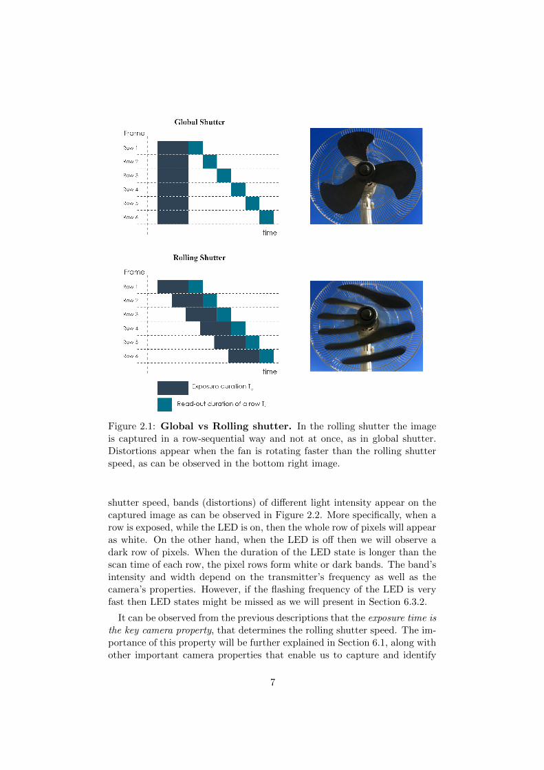
Figure 2.1: Global vs Rolling shutter. In the rolling shutter the imageis captured in a row-sequential way and not at once, as in global shutter.Distortions appear when the fan is rotating faster than the rolling shutterspeed, as can be observed in the bottom right image.
shutter speed, bands (distortions) of different light intensity appear on thecaptured image as can be observed in Figure 2.2. More specifically, when arow is exposed, while the LED is on, then the whole row of pixels will appearas white. On the other hand, when the LED is off then we will observe adark row of pixels. When the duration of the LED state is longer than thescan time of each row, the pixel rows form white or dark bands. The band’sintensity and width depend on the transmitter’s frequency as well as thecamera’s properties. However, if the flashing frequency of the LED is veryfast then LED states might be missed as we will present in Section 6.3.2.
It can be observed from the previous descriptions that the exposure time isthe key camera property, that determines the rolling shutter speed. The im-portance of this property will be further explained in Section 6.1, along withother important camera properties that enable us to capture and identify
7

Figure 2.2: Band formation and LED state. The size (width) of eachband, corresponds to the duration of the LED state (on or off).
the transmitted light patterns (LED states).
Modern smartphone cameras are able to capture around 20 to 30 framesper second which is called frame rate. As a consequence, by exploitingthe rolling shutter effect, along with capturing multiple frames per second,the smartphone can obtain multiple encoded data (LED states). However,modern smartphones do not offer a stable frame rate. For example, theframe rate of Samsung Galaxy S3 fluctuates between 21 and 29 frames persecond. This phenomenon introduces synchronization problems between thetransmissions and receptions. Firstly, a fluctuating reception rate could leadto fragmented data between more than one frame. In addition, due to thediscontinuity of the receptions there is high probability of missing data.Thus, any camera-based visible light communication link has to take intoconsideration these synchronization challenges, when it comes to building areliable communication link.
2.3 DynaLight’s Requirements
In this section we present the basic requirements that our system needs tomeet. This thesis presents DynaLight, a camera-based line-of-sight visiblelight communication system. The system requirements, are mainly focusedon creating a flexible, reliable, and flicker free visible light communicationlink for various smartphones.
Adaptive to Distance: The goal of this project is to create a flex-ible system that has the ability operate in different distances. Distanceadaptation regards the creation of a link that can modify its properties, inaccordance with the distance between the transmitter and the receiver. Thismeans, that the channel capacity of the link should change with respect tothe detected distance. Our system should be able to estimate the distancebetween the transmitter and the receiver and adjust the channel capacity
8

accordingly. The smaller the distance, the greater the channel capacity, dueto the fact that the transmitter is closer to the camera. In this case, theamount of information that can be extracted increases. The system has tobe able to calculate the feasible amount of information that can transmit inany distance.
Reliable: Reliability can be achieved in different levels. In this work, werelate the channel reliability with overcoming the problems, introduced bythe camera-based VLC links. As has been mentioned in the previous sec-tions, the wide diversity in the used camera hardware introduces challengesfrom controlling the camera’s properties to synchronizing the transmissionswith the receptions. In addition, our system should operate in such a wayso as to avoid introducing flickering effects that can be annoying to humans.
Utilize inexpensive hardware: We aim at creating a low cost system,that can support inexpensive and resource constrained platforms both forthe transmitter and the receiver. As a result, we prefer to avoid exploitinghigh-end hardware not only for cost reasons but also for identifying possiblelimitations and increase our system’s applicability. It has to be clarifiedthat in this project we do not use the flash LED of the phone or any otherexternal flashing device. More information about this decision is providedin Appendix A.
9

10

Chapter 3
Related Work
This chapter discusses the visible light communication projects that inspiredour work. In Section 3.1, we begin by presenting some of the key priorresearch works in the field of visible light communication. Then, in Section3.2, we focus only camera-based research works. Both Sections 3.2.1 and3.2.2, thoroughly discuss related projects that create data communicationlinks, utilizing LEDs or LCD screens accordingly. Moreover, Section 3.2.3,discusses camera-based works designed for indoor localization. Finally, inSection 3.2.4, we present a short overview of the projects that influencedthis thesis.
3.1 VLC projects using LEDs or Photodiodes
The majority of the early VLC research work is mainly focused on creatinghigh-speed data links, using specialized hardware [20] and photodiodes. Inthese projects, RGB [20, 30] and phosphorecent white LEDs [14, 15] areutilized. Furthermore, variations of OOK modulation schemes are used, aswell as more complicated schemes such as QAM or DMT/OFMD modu-lation [12, 20]. Photodiodes were exploited as receivers, due to their highbandwidth, that can support complicated modulation schemes.
In 2012, the IEEE, published a VLC standard known as 802.15.7 [27],which specifies the hardware, modulation and channel coding for variousapplications. More recent projects focus on LED to LED communication[13, 29, 31, 32] and LED to photodiodes communication [19]. The goal ofthese projects is to create efficient, low cost and high-rate VLC links.
3.2 Camera-based VLC
This section focuses on projects that use cameras as receivers for both cre-ating data communication links and localization. All the following camera-based related projects were published after 2012, which highlights that the
11

present thesis deals with currently open research problems and recent engin-eering work.
3.2.1 LED to Camera Communication
LED to camera communication systems, have been investigated in severalrecent works, focusing on smartphone implementations.
In [11], the authors present how a smartphone camera can be utilized asa receiver using the rolling shutter capturing mechanism. The entire workfocuses on how to transmit data between a LED and a smartphone camera.The main problems that are addressed in this work are, firstly realizing howthe camera sensor operates and then how to modulate data, so that they canbe captured and decoded by the receiver. The authors extensively discussthe rolling shutter effect, which is used by the CMOS cameras and explainthe row-sequential capturing method. Then, they explain the utilized OOKand Manchester encoding and decoding scheme, achieving a data rate of1-3.1kbps, using 640x480 images and 20fps. However, the proposed systemintroduces noticeable flickering while operating on the visible range of 40Hz.The authors overcome the flickering by imposing a DC bias on the signal,which decreases its dynamic range and the SNR at the receiver, but requiresa more complex driving hardware. Another drawback is that the systemoperates only at close proximity (8-9cm), which reduces the link’s flexibilityand applicability. Despite the several drawbacks, the main contribution ofthis work is that it provides a proof-of-concept of camera-based VLC inmobile phones. We also take advantage of the rolling shutter effect and theOOK and Manchester encoding. The main differences with our work are:
• Our system operates above frequencies that cause direct or indirectflickering (>2 kHz).
• Our system is adaptive to distance and can operate from 20-120cm.
A similar study was conducted in [28], that uses undersampled frequencyshift on-off keying (UFSOOK) to overcome the flickering effect that waspresented in the previous study. However, the authors achieve a very lowdata rate of 0.5 bits per frame, in extremely low SNR conditions, which isconsidered very limited and not applicable.
RollingLight [22], is a very recent work (2015) in the field of LED to cam-era communication. The authors present a line of sight to camera commu-nication system. The main goal of this study is to overcome the diversity,that is introduced by off-the-shelf smartphones that use the rolling shut-ter. This diversity is caused by the heterogeneous sampling rates of thephones, that cause difficulties in synchronizing the transmitter and the re-ceiver. The authors extensively studied and found an unpredictable andvarying idle time gap between two consecutive frames. This phenomenon
12
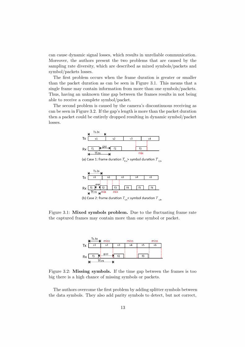
can cause dynamic signal losses, which results in unreliable communication.Moreover, the authors present the two problems that are caused by thesampling rate diversity, which are described as mixed symbols/packets andsymbol/packets losses.
The first problem occurs when the frame duration is greater or smallerthan the packet duration as can be seen in Figure 3.1. This means that asingle frame may contain information from more than one symbols/packets.Thus, having an unknown time gap between the frames results in not beingable to receive a complete symbol/packet.
The second problem is caused by the camera’s discontinuous receiving ascan be seen in Figure 3.2. If the gap’s length is more than the packet durationthen a packet could be entirely dropped resulting in dynamic symbol/packetlosses.
Figure 3.1: Mixed symbols problem. Due to the fluctuating frame ratethe captured frames may contain more than one symbol or packet.
Figure 3.2: Missing symbols. If the time gap between the frames is toobig there is a high chance of missing symbols or packets.
The authors overcome the first problem by adding splitter symbols betweenthe data symbols. They also add parity symbols to detect, but not correct,
13
errors and overcome the second problem. Both solutions are facilitated bythe fact that they utilize a very recent high resolution phone (iPhone 5s)and a big light source of 60cm×60cm for their experiments, which assist inachieving a high data rate and coverage (light size). This means that theycan achieve a big bandwidth that enables them to have packets that includesplitter symbols, sequence numbers and parity bits. Finally, the authorsimplement a real-time iOS application that can achieve a data rate of 11.32bytes per second.
In our project we take advantage of:
• The unsynchronized communication problem formulation.
• The band-width analysis, but we extend it and show how the cameraparameters affect the size of the detected bands.
Furthermore, our work differs in the following topics:
• We overcome the mixed packets by making sure that a complete packetcan be decoded from every captured frame.
• We try to synchronize the transmission by minimizing the effect of thetime gap jitter.
• We do not use high-end smartphones or big light sources.
Exploiting low cost hardware certainly limits the system’s performancebut proves that performance gain can be achieved by utilizing better hard-ware.
The previously mentioned works either use OOK or BFSK for modulatingsingle color LEDs. Colored LEDs have also been studied. Color-shift keying(CSK) was outlined in [27] and refers to transmitting data imperceptiblythrough the variation of the color emitted by red, green, and blue lightLEDs. There are several studies such as [24] and [25] that use CSK and butdo not utilize CMOS cameras that exploit the rolling shutter.
3.2.2 Screen to Camera Communication
There are several prior works that utilize displays for delivering informationbits to cameras [16, 18, 33]. These studies focus mostly on transmitting“static” information, similar to barcodes or QRCodes, rather than build-ing communication links as done in LED to camera works. Nevertheless,these systems also face the same receiver limitations, since they are usingsmartphone cameras.
VRCodes [33], is the study that influenced display to camera commu-nication. The authors present a novel active visual tag, which utilizes all
14
dimensions of color, time and space and show how digital information canbe embedded without being obstructive to human eyes. In their setup, theyutilize ordinary displays and rolling-shutter cameras similarly to our LEDto camera communication systems. However, they do not address practicalchallenges, such as the signal losses that were explained in the previoussection with respect to synchronization. In COBRA [16], the authors pro-pose information encoding into specially designed 2D color barcodes. Theyuse color information of pixels to improve SNR and stream them betweensmall-size screen and low-speed camera, where most or all the data flowsalong a particular direction. As most of the prior works, they also do nottackle information losses but simply repeat each packet twice. Finally, in[18], the authors present Strata, a layered coding scheme for visual commu-nication that extends the known QR codes. The study is influenced by thehierarchical modulation from traditional RF communication, resulting in in-formation being organized in multiple layers into the same code area. Theimportance of the layered coding schemes is highlighted by the heterogeneityin the smartphone cameras, that cause different amount of information tobe extracted with respect to distance or channel conditions.
3.2.3 Indoor Localization
Indoor localization is a field where camera-based communication can bewidely applied due to the popularity of smartphones and LED lighting. How-ever, there are still very limited real applications utilizing VLC localization.To the best of our knowledge, only ByteLight [2] offers shop location-basedservices, using LED lighting along with sub-meter accuracy and sub-secondlatency. Nevertheless, there are several research projects [21, 23, 26, 34] thatpresent indoor localization systems.
In Luxapose [21], the authors present a system that uses slightly-modifiedcommercial LED luminaries (light beacons), along with smartphone camerasto provide accurate positioning compared to other RF-based approaches.The authors present a new localization approach based on the promising“angle of arrival” method. This method utilizes the projections of mul-tiple light sources (with known positions) in the camera sensor, to estimatethe phone’s position. The aim of the authors is to achieve sub-meter ac-curacy compared to other similar pre-existing systems. Indoor localizationsystems do not need to deal with synchronization and reliability problemsas previously discussed in RollingLight, since the light sources continuouslyre-transmit their location ID. Furthermore, the authors assume that the sys-tem operates in fixed distances between the light sources and the smartphonedevice.
The authors conducted several experiments with respect to the cameraparameters. In their analysis they prove that, in order to improve the SNRand boost the contrast ratio between the bright and dark bands, the para-
15

meters that control the speed of the rolling shutter should be minimized(i.e. exposure time). They further propose a complete image processingpipeline for transmitter detection. The author’s utilize the transmitter de-tection for identifying the location of the transmitters in the frame, decodethe transmitted light source ID and estimate position of the receiver.
In DynaLight we:
• Base the transmitter detection on the same pipeline, but we furtherimprove the amount of information that we can fit in the detected blobby 40%.
• Implement a different decoding pipeline suitable for the used modula-tion technique.
Furthermore, in Luxapose, the image processing and decoding is per-formed entirely in a cloud server, which offloads the processing from thephone, but it adds additional communication overhead, with respect touploading high resolution images in a server. Last but not least, the au-thors exploit a smartphone (Nokia Lumia 1020) that offers huge resolution(7712×5360) and extensive camera parameter control compared to Androidphones. As a consequence, the authors do not face effects caused by lowcost cameras and the limited camera control.
In DynaLight we:
• We perform the image processing locally in the smartphone.
• Do not use high-end smartphones that increases the range of marketsmartphones that it can support.
In [26], the authors propose a non line of sight localization system. Theauthors present a localization system but also overcome the unsynchroniza-tion problems in a different way than RollingLight. The authors use binaryfrequency shift keying and they achieve 1.25 bytes per second exploiting 720pimages at 30 fps and custom made transmitters. A sliding window approachis presented after capturing and concatenating all the captured frames. Theyalso identify the discontinuities in frame receptions as discussed in Rolling-Light, but use two Hanning windows to smooth the discontinuities in thecaptured frames. We believe that this approach is impractical with respectto real-time decoding since all the frames have to be first captured beforethe beginning of the decoding. In addition, they do not mention whethertheir approach overcome the frame rate diversity between different phones.On the other hand, the authors introduce an algorithm, that is partly usedby DynaLight, for overcoming the limited camera control that is introducedby the Android operating system. Last but not least, they study the impactof the background noise and also how camera focus affects decoding. Our
16

system is also evaluated in different ambient light conditions and we provethat is robust to noisy environments.
Other interesting projects include Epsilon [23] and PIXEL [34]. In theformer, the authors exploit LED lamps, as anchors, along with a custommade light sensor that is connected to the phones audio jack. In the latter,the authors present light-weight visible light positioning solution, that isdesigned to accommodate resource constrained mobile devices, such as smartglasses. Moreover, the authors present a color-based modulation scheme,that handles users mobility and a fast positioning algorithm that can executein real-time.
3.2.4 Summary
In this section, we summarize the most important camera-based projectsthat influenced this thesis. Table 3.1 summarizes the key camera-basedworks that we based our system on. It can be observed that all the pro-jects utilized different platforms, that offer different flexibility. Based onDynaLight’s requirements that were presented in Chapter 2, we present therelated features of our project. It has to be mentioned that only DynaLighthas a dynamic data rate due to its adaptive behavior. All the design choiceswill be thoroughly explained in the following chapters.
Table 3.1: An overview of most important projects discussed inthis chapter. An asterisk (?) means the content of the cell is unknown oruncertain.
Project Platform/ Exposure Control Resolution Modulation Coverage Data Rate
CMOS for VLC [11] Android/ Low 480pOOK
+Manchester Encoding
8-9cm 1-3 kbps
Visual LightLandmarks [26]
iOS/ Low 720p BFSK 1m 1.25 bytes/sec
Luxapose [21] Windows/ High 5360pPWM
+Manchester Encoding
2-3m *
RollingLight [22] iOS/ High 1080p FSK 160cm 11.32 bytes/sec
DynaLight Android/ Low 1080pOOK
+Manchester Encoding
20-120cm Dynamic *
17

18

Chapter 4
Overview
This chapter gives a short overview of the developed system. In Section4.1, we present the main components of our system, while in Section 4.2 webriefly discuss the system’s fundamental functionalities.
4.1 System Components
DynaLight is a VLC system designed for data communication. Therefore,it consists of a transmitter and a receiver facing one another. Both of themoperate together so as to create an adaptive and reliable, visible light com-munication link.
The transmitter consists of a microcontroller and a LED. The microcon-troller is used to modulate the LED and encode information. Information isencoded in such a way, that the average emitted light power is constant anddoes not create noticeable flickering. More specifically, the LED is turnedon and off at a rate that is high enough for the human eye to notice.
On the other hand, the receiver’s side consists of the back-facing cameraof a smartphone. The phone takes advantage of the rolling shutter capturingmechanism that was explained in Section 2.2. In order to be able to detectthe transmitter light signal, we need to tune the camera sensor so that wecan observe the white and dark distortions. As has been mentioned in theprevious sections, by lowering the exposure time we are able to control therolling shutter speed. Having a fast rolling shutter enables the camera toidentify the white and dark bands that follow the lighting pattern of thetransmitter, as can be seen in Figure 4.1. By continuously capturing imagesand applying image processing techniques, we are able, first to identify thelight source and then decode the transmitted lighting patterns.
DynaLight has to be flexible with respect to distance and ensure reliabletransmissions. Having a single transmitter and receiver facing one anotheris impractical due the fact that the transmitter side is not able to measuretheir distance and adjust the transmitter amount of information accordingly.
19

(a) Auto Exposure (b) Low Exposure (c) Encoded Signal
Figure 4.1: Camera exposure settings. In both pictures the LED ismodulating at a frequency of 200 Hz. By lowering the exposure time weare able to observe white and dark bands (distortions), that correspond tothe transmitted signal. Dark and white bands correspond to 0 and 1 bitrespectively.
Additionally, it is impossible to automatically synchronize the two compon-ents because they are not connected. In DynaLight, both sides are equippedwith both a transmitter and a receiver as depicted in Figure 4.2 and 4.3.With the proposed setup both sides are able to estimate their distance andmaintain synchronization. In the following section, we briefly present themain functionalities of our system but the transmitter’s and receiver’s sidewill be thoroughly explained in Chapters 5 and 6 respectively.
4.2 Basic Functionalities
In this section we present the main operations of each system component.The basic functionalities of the transmitter refer to encoding, packet con-struction and modulation. On the receiver side, we perform the transmitterdetection, distance estimation, image processing and decoding. The twotransmitters and two receivers facilitate in calculating of the ideal channelcapacity for each distance and for maintaining synchronization.
Encoding/Modulation: As it has been mentioned above, the trans-mitter consists of a microcontroller that is used for creating the lightingpatterns. The data bits are first encoded then organized into packets andthen transmitted using high rate light modulations. In order to create aflicker free system OOK plus Manchester encoding was utilized as will befurther explained in Chapter 5.
Transmitter Detection: The transmitter detection regards identifyingwhich areas of the captured frame contain decodable information. In Dyn-aLight, we base the transmitter detection mechanism on the one that was
20

Figure 4.2: DynaLight’s overview. The system consists of two transmit-ters and receivers that communicate via “invisible” light modulation. Thegrey boxes highlight the sections where the main contributions of this thesiscan be found.
presented in Luxapose [21]. We further enhance the proposed mechanismby adding an additional image processing step that increases the detectedarea by 40%, meaning that we are able to decode more data. More detailsabout our enhancement are provided in Section 6.2.1.
Distance Estimation: Since we are creating a line-of-sight visible lightcommunication link, that could operate in multiple distances, the receivershould be able to measure the distance between the two main system com-ponents in order to adjust its channel’s capacity accordingly. The distanceestimation is based on the detected transmitter size of the previously men-tioned operation. The bigger the detected transmitter the closer the twocomponents are and vise versa. The system’s design enable us to performthe distance estimation in both sides. More details will be presented in Sec-tion 7.1.
Image Processing/Decoding: This operation refers to all the im-age processing techniques, that DynaLight exploits, so as to decode thetransmitted information. It has to be clarified that we did not base thesesoperations on Luxapose [21], as done with transmitter detection. More in-
21

Figure 4.3: DynaLight’s setup. The red circles show the transmitterswhile the green ones show the receivers.
formation about the challenges that we encountered can be found in Section6.2.
Channel Capacity Calculation: The amount of information that thetransmitter sends is related not only to the distance of the two componentsbut also on the fact that we wish to avoid having the mixed symbol/packetproblem that was mentioned in Section 3.2.1. Once the distance is estim-ated the receiver sets the appropriate amount of information to be sent toits connected transmitter, as shown in Figure 4.2 (arrow from phone to mi-crocontoller). More information on the channel capacity calculation can befound in Section 7.1.2
Synchronization: As in all camera-based VLC systems, synchroniza-tion refers to the problem of missed data due to fluctuation reception ratethat was discussed in Section 3.2.1. The system tries to minimize the syn-chronization problem in two ways. First, we synchronize the the start oftransmissions and then we try to maintain a constant reception rate. Moreinformation about this problem can be found in Section 7.2.2.
22

Chapter 5
Transmitter
This chapter describes the first component of the developed system whichis the transmitter (Tx). In Section 5.1, the selected modulation techniqueis presented, while Section 5.2, discusses the packet structure that is usedfor transmitting data and how data is encoded and transmitted. Section 5.3presents the implementation details with respect to the selected hardware.
5.1 Modulation Technique
In order to encode data, the developed system modulates signals on theLED transmitter in such a way that data can be accurately decoded bythe receiver, as well as not generate direct or indirect flicker (stroboscopiceffect). As it has already been discussed in Chapter 3, recent research hasshown that different modulation techniques have already been experimentedsuch as, OOK, PWM or BFSK.
In this work, we chose to exploit On-off keying (OOK) along with Manchesterencoding. OOK denotes the simplest form of amplitude-shift keying (ASK)modulation in which, digital data “0” and “1” are represented with turn-ing the LED on or off respectively. However, utilizing just OOK introducesflickering when it comes to representing long sequences of “0” or “1”. Bycombining OOK with Manchester encoding, each “0” and “1” bit is represen-ted by a sequence of “01” and “10” symbols accordingly. As a consequence,it is impossible to have more than two consecutive matching symbols, whicheliminates the OOK flickering. Moreover, the number of 0s and 1s is thesame regardless the encoded data. Figure 5.1 depicts the difference betweenplain OOK and combining it with Manchester encoding. In the first case,the long sequence of “0” bit will create noticeable flickering if the modu-lation frequency is not high enough, while in the second case the symbolproportion is more balanced.
OOK, plus Manchester encoding, is appealing for its simplicity. Never-theless, there are cases where other transmitters can lower its robustness.
23
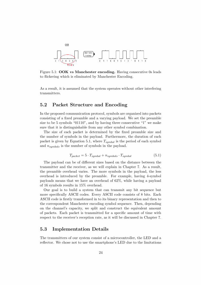
Figure 5.1: OOK vs Manchester encoding. Having consecutive 0s leadsto flickering which is eliminated by Manchester Encoding.
As a result, it is assumed that the system operates without other interferingtransmitters.
5.2 Packet Structure and Encoding
In the proposed communication protocol, symbols are organized into packetsconsisting of a fixed preamble and a varying payload. We set the preamblesize to be 5 symbols “01110”, and by having three consecutive “1” we makesure that it is distinguishable from any other symbol combination.
The size of each packet is determined by the fixed preamble size andthe number of symbols in the payload. Furthermore, the duration of eachpacket is given by Equation 5.1, where Tsymbol is the period of each symboland nsymbols is the number of symbols in the payload.
Tpacket = 5 · Tsymbol + nsymbols · Tsymbol (5.1)
The payload can be of different sizes based on the distance between thetransmitter and the receiver, as we will explain in Chapter 7. As a result,the preamble overhead varies. The more symbols in the payload, the lessoverhead is introduced by the preamble. For example, having 4-symbolpayloads means that we have an overhead of 62%, while having a payloadof 16 symbols results in 15% overhead.
Our goal is to build a system that can transmit any bit sequence butmore specifically ASCII codes. Every ASCII code consists of 8 bits. EachASCII code is firstly transformed in to its binary representation and then tothe correspondent Manchester encoding symbol sequence. Then, dependingon the channel’s capacity, we split and construct the equivalent amountof packets. Each packet is transmitted for a specific amount of time withrespect to the receiver’s reception rate, as it will be discussed in Chapter 7.
5.3 Implementation Details
The transmitters of our system consist of a microcontroller, the LED and areflector. We chose not to use the smartphone’s LED due to the limitations
24
of the Android operating system. More information can be found in SectionsA.1 and A.2 about this decision.
The LED modulation, control and data encoding is performed completelyon the microcontroller, which in our case is an Arduino MEGA ADK [1].In order to achieve the required modulation frequencies and accuracy, weused the microntroller’s timer interrupts. More specifically, we turn on andoff the LED based on the timer ticks using an interrupt handler. Arduinohas a system clock of 16MHz and the timer clock frequency is set by theprescale factor. The desired output frequency for the LED is around 3 kHzso we choose a prescaler value of 256. More information about the selectedfrequency can be found in Chapter 6.
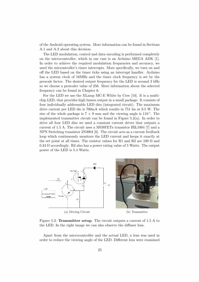
For the LED we use the XLamp MC-E White by Cree [10]. It is a multi-chip LED, that provides high lumen output in a small package. It consists offour individually addressable LED dies (integrated circuit). The maximumdrive current per LED die is 700mA which results in 751 lm at 9.5 W. Thesize of the whole package is 7 × 9 mm and the viewing angle is 110 . Theimplemented transmitter circuit can be found in Figure 5.2(a). In order todrive all four LED dies we used a constant current driver that outputs acurrent of 1.5 A. The circuit uses a MOSFETs transistor IRL1004 [7] and aNPN Switching transistor 2N3904 [8]. The circuit acts as a current feedbackloop which continuously monitors the LED current and keeps it exactly atthe set point at all times. The resistor values for R1 and R2 are 100 Ω and0.34 Ω accordingly. R2 also has a power rating value of 5 Watts. The outputpower of the LED is 5.4 Watts.
(a) Driving Circuit (b) Transmitter
Figure 5.2: Transmitter setup. The circuit outputs a current of 1.5 A tothe LED. In the right image we can also observe the diffuser lens.
Apart from the microcontroller and the actual LED, a lens was used inorder to reduce the viewing angle of the LED. Different lens were examined
25

in order to decide on the most effective one. We decided to use the diffuser[3], which offers the brightest beam and a 20 viewing angle. The size ofthe lens is 2 × 2cm. The advantages and effects of the diffuser can be foundin Chapter 8.
An additional reason for selecting the aforementioned microcontroller is,the offered flexibility when it comes to connecting it with an Android phone.It is equipped with a USB host interface, given by MAX3421E IC [6], whichallows the Arduino to connect and interact with any type of device, thathas a USB port. We use this interface for sending control commands to themicrocontroller, as well as the data to be transmitted, which in our case arethe ASCII codes.
26

Chapter 6
Receiver
This chapter describes the second fundamental component of the developedsystem which is the receiver (Rx). In Section 6.1, all the important cam-era parameters are discussed along with their importance in receiving thetransmitted signal. Then, in Section 6.2, a detailed description of the im-age processing pipeline is presented, followed by Section 6.3 which includesimportant implementation details and limitations.
6.1 Camera Control
As it has been mentioned several times in the previous sections, smartphonesuse the rolling shutter capturing mechanism in which, the frames are cap-tured in a row sequential way, as shown in Figure 2.2. In order to get thedepicted bands in the captured frame, there are several camera parametersthat have to be tuned appropriately.
Exposure time & ISO: The most important parameter is the expos-ure time. Exposure time, determines the duration that each pixel collectsphotons. In other words, exposure time affects the amount of light in animage. In practice, short exposure values increase the ability to distinguishbetween the dark and white bands. A closely related parameter is film speed(ISO setting), which affects the amount of photons that are required to sat-urate a pixel. In [21], the authors argue that for the best performance andin order to improve the SNR, the exposure time and film speed have to beminimized.
Scan rate & Resolution: As has been mentioned above, the frames arecaptured in a row sequential way, so we can consider each individual frame asour signal, and the pixel-rows can be regarded as the samples. The numberof rows in a frame is determined by the camera resolution. As a result, thetime to scan a new frame refers to the time that the sensor requires to scan
27
all the rows of the frame. This property is named camera scan rate and isthe rolling shutter speed. The camera scan rate can also be considered asthe sampling rate of our pixels (samples). Certainly, the scan rate dependsalso on the time that is needed to scan a single row.
Each “pixel-row” is first exposed and then read. Due to the rolling shuttereffect, as shown in Figure 2.1, the time to scan a single frame is given fromEquation 6.1, where Te is the exposure time and Tr is the time to read asingle row.
Tframe = Te + Tr ·Rows (6.1)
All the previously mentioned parameters affect the width of each capturedband. The width of each band is expressed in pixels and represents how longthe light was on or off in the transmitter and as a result it affects the packetdecoding. In [22], it is proved that the width W of each band can be givenby Equation 6.2 where f is the modulation frequency of the transmitter.
W =1
2fTr(6.2)
Combining Equations 6.1 and 6.2, we present Equation 6.3, where we re-late width of each band with the most important camera parameters, mean-ing the exposure time, the scan rate and the number of rows (resolution).
W =1
2fTframe−Te
Rows
(6.3)
As it can be observed in Equation 6.3, the width of each band does notdepend on the orientation of the camera, the size of the LED or the distancebetween the LED and the smartphone.
Frames per second: Finally, the number of frames that a camera canobtain per second is significantly important, when it comes to specifying theVLC link’s data rate. Nevertheless, the actual bandwidth is also determinedby the ability to synchronize the two components. This challenge will befurther explained in Chapter 7.
Other Camera Functions
Cameras usually have additional functions that affect the captured imagessuch as antibanding, video stabilization, white balance and auto-focus. An-tibanding is a function that decreases fluctuations in brightness of frames orimages, caused by a light source oscillations. Video stabilization is a familyof techniques utilized to reduce blurring caused by motion of a camera. Fur-thermore, white balance refers to methods that correct the colour balance of
28
the lighting in an image. Finally, auto-focus concerns methods for adjustingthe camera lens so as to obtain focus on a subject.
Challenges
In practice, smartphones are limited by the operating system and do notallow applications to modify some of the previously mentioned parameters.The scan rate and the time to scan a single row are fixed parameters of thecamera sensor and cannot be tuned. On the other hand, exposure time, filmspeed (ISO), resolution and the frames per second can be set by a developedapplication. However, the value range is very limited and varies from phoneto phone. As a result, Android phones do not offer much flexibility comparedto iOS or Windows phones. Moreover, the exposure range may also belimited by the camera sensor due to the limited hardware capabilities. Moreinformation about the selected values for each parameter can be found inSection 6.3
6.2 Image Processing
Once the camera sensor has been tuned appropriately (low exposure time),and has obtained a frame with recognisable white and dark bands, the fol-lowing steps regard, the image processing methods that are required, inorder to convert bands to useful data bits. DynaLight’s image processingpipeline exploits methods that are offered by the OpenCV image processinglibrary.
Before discussing the decoding method we first need to highlight the im-portance of the transmitter’s detection. DynaLight is a LoS system and isdesigned to operate in close distances from 20 cm to 120 cm. As a result,the transmitter light will not be spread out in the whole frame as can beobserved from Figure 6.2(a). Furthermore, we assume that the transmitterdoes not have to be always in the center of the frame, as in the previouslymentioned figure. This fact gives prominence to the need of a transmitterdetection mechanism, that will identify, which part of the image containsdecodable information.
6.2.1 Transmitter Detection
As has been mentioned above, by selecting the minimum exposure settings,the image will be brighter in the area of the transmitter plus, creating a vis-ible “aura” around it with respect to its intensity. The greater that area is,the more bands are visible, which results in the extraction of further usefulinformation. We base transmitter detection to the one that was presentedin Luxapose [21]. We further improve the proposed transmitter detection
29
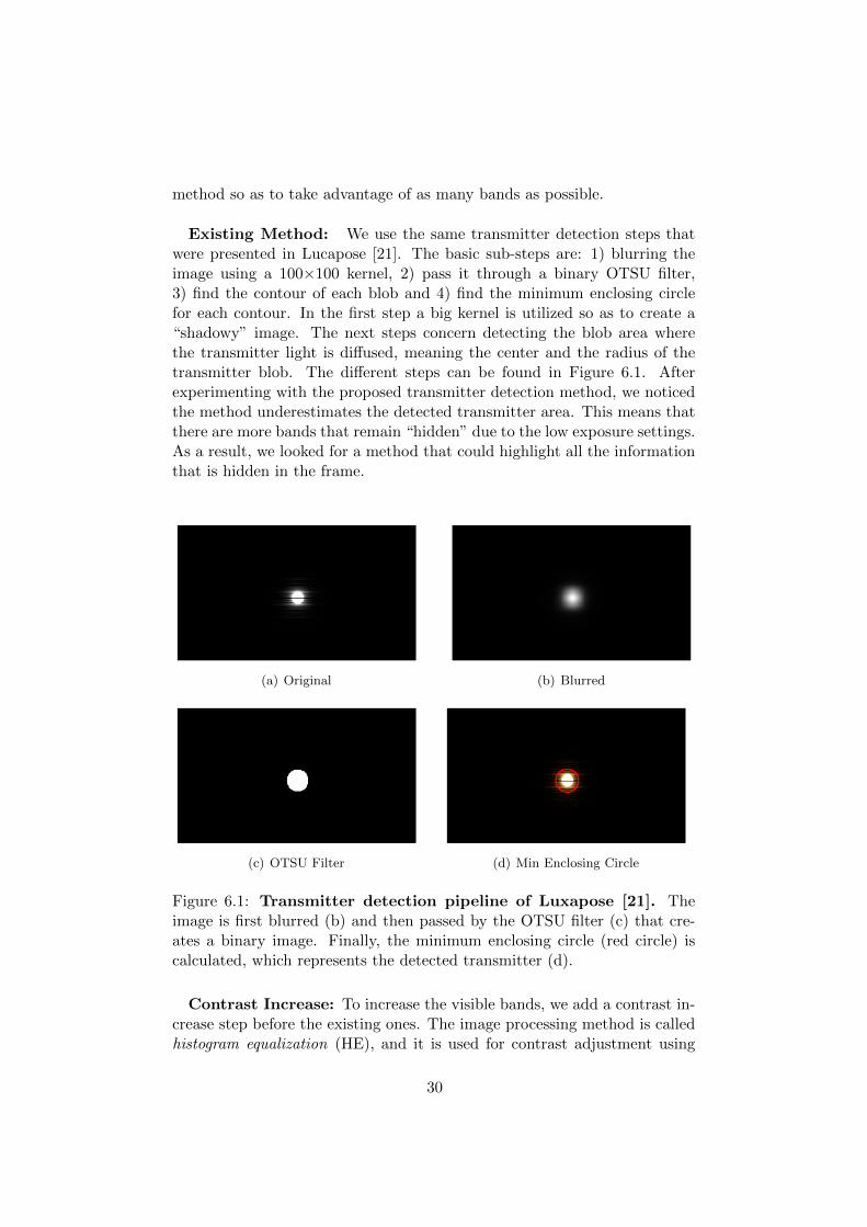
method so as to take advantage of as many bands as possible.
Existing Method: We use the same transmitter detection steps thatwere presented in Lucapose [21]. The basic sub-steps are: 1) blurring theimage using a 100×100 kernel, 2) pass it through a binary OTSU filter,3) find the contour of each blob and 4) find the minimum enclosing circlefor each contour. In the first step a big kernel is utilized so as to create a“shadowy” image. The next steps concern detecting the blob area wherethe transmitter light is diffused, meaning the center and the radius of thetransmitter blob. The different steps can be found in Figure 6.1. Afterexperimenting with the proposed transmitter detection method, we noticedthe method underestimates the detected transmitter area. This means thatthere are more bands that remain “hidden” due to the low exposure settings.As a result, we looked for a method that could highlight all the informationthat is hidden in the frame.
(a) Original (b) Blurred
(c) OTSU Filter (d) Min Enclosing Circle
Figure 6.1: Transmitter detection pipeline of Luxapose [21]. Theimage is first blurred (b) and then passed by the OTSU filter (c) that cre-ates a binary image. Finally, the minimum enclosing circle (red circle) iscalculated, which represents the detected transmitter (d).
Contrast Increase: To increase the visible bands, we add a contrast in-crease step before the existing ones. The image processing method is calledhistogram equalization (HE), and it is used for contrast adjustment using
30

the image’s histogram. Histogram equalization is mainly useful for increas-ing the global contrast of an image. Contrary to that, adaptive histogramequalization (AHE) is used increasing the local contrast of an image butit over-amplifies noise. In our image processing pipeline, Contrast LimitedAHE (CLAHE) is utilized, which is used for global HE but also limits thenoise of over-amplification. The effect of contrast increase can be observedin Figure 6.2(b). After increasing the image’s contrast, the rest of the trans-mitter detection steps. The difference in the detected blob size can be seenin Figure 6.2(c). We compare our blob detection pipeline with Luxapose inSection 8.1.
(a) Original frame (b) After Constrast Increase (c) Detected blob with(green) and without (red)contrast increase
Figure 6.2: Impact of contrast increase. After increasing the contrastof the image we can observe that more bands can be identified (b). In theright image (c) the red circle represents the detected blob of Luxapose [21].The green circle shows the improvement of the contrast increase.
6.2.2 Data Decoding
Once the transmitter is located in the image, we continue by examiningonly the corresponding blob sub-region independently to decode data. InLuxapose and RollingLight, different modulation techniques were exploitedmeaning that we had to implement our own decoding pipeline. Further-more, by utilizing different hardware, we were able to identify and overcomeadditional limitation that the other works did not encountered. It has to beclarified that we do not crop the transmitter area before processing it.
The complete decoding pipeline is depicted in Figure 6.5. It has to beclarified that we take advantage of the same contrast increase method alsoin the decoding pipeline. The additional steps are presented bellow.
Blurring: We observed that the contrast increase introduces some noisethat can be smoothed exploiting the OpenCV blurring method. This blur-ring step is different from the aforementioned in the transmitter detection.In this phase a very small kernel (3×3) is used, for averaging the pixel values
31
and reduce noise.
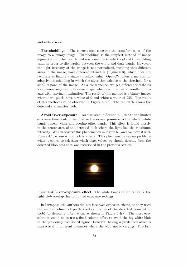
Thresholding: The current step concerns the transformation of theimage to a binary image. Thresholding, is the simplest method of imagesegmentation. The most trivial way would be to select a global thresholdingvalue in order to distinguish between the white and dark bands. However,the light intensity of the image is not normalized, meaning that differentareas in the image, have different intensities (Figure 6.3), which does notfacilitate in finding a single threshold value. OpenCV, offers a method foradaptive thresholding in which the algorithm calculates the threshold for asmall regions of the image. As a consequence, we get different thresholdsfor different regions of the same image, which result in better results for im-ages with varying illumination. The result of this method is a binary image,where dark pixels have a value of 0 and white a value of 255. The resultof this method can be observed in Figure 6.5(c). The red circle shows thedetected transmitter blob.
Avoid Over-exposure: As discussed in Section 6.1, due to the limitedexposure time control, we observe the over-exposure effect in which, whitebands appear wider and overlap other bands. This effect is found mostlyin the center area of the detected blob where the light has the maximumintensity. We can observe this phenomenon in Figure 6.3 and compare it withFigure 4.1, where white blob is absent. This phenomenon causes problemswhen it comes to selecting which pixel values we should decode, from thedetected blob area that was mentioned in the previous section.
Figure 6.3: Over-exposure effect. The white bands in the center of thelight blob overlap due to limited exposure settings.
In Luxapose, the authors did not face over-exposure effects, so they usedthe middle column of pixels (vertical radius of the detected transmitterblob) for decoding information, as shown in Figure 6.4(a). The most easysolution would be to use a fixed column offset to avoid the big white blobin the previously mentioned figure. However, having a predefined offset isimpractical in different distances where the blob size is varying. This fact
32
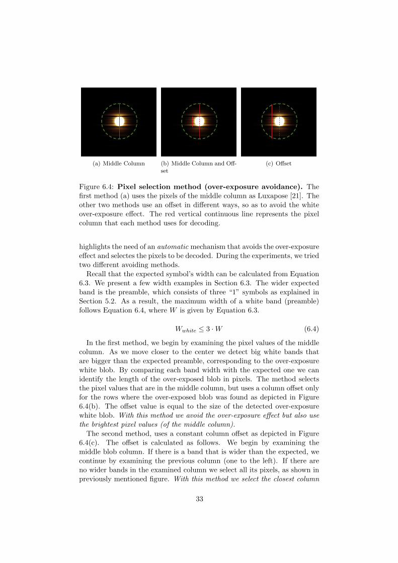
(a) Middle Column (b) Middle Column and Off-set
(c) Offset
Figure 6.4: Pixel selection method (over-exposure avoidance). Thefirst method (a) uses the pixels of the middle column as Luxapose [21]. Theother two methods use an offset in different ways, so as to avoid the whiteover-exposure effect. The red vertical continuous line represents the pixelcolumn that each method uses for decoding.
highlights the need of an automatic mechanism that avoids the over-exposureeffect and selectes the pixels to be decoded. During the experiments, we triedtwo different avoiding methods.
Recall that the expected symbol’s width can be calculated from Equation6.3. We present a few width examples in Section 6.3. The wider expectedband is the preamble, which consists of three “1” symbols as explained inSection 5.2. As a result, the maximum width of a white band (preamble)follows Equation 6.4, where W is given by Equation 6.3.
Wwhite ≤ 3 ·W (6.4)
In the first method, we begin by examining the pixel values of the middlecolumn. As we move closer to the center we detect big white bands thatare bigger than the expected preamble, corresponding to the over-exposurewhite blob. By comparing each band width with the expected one we canidentify the length of the over-exposed blob in pixels. The method selectsthe pixel values that are in the middle column, but uses a column offset onlyfor the rows where the over-exposed blob was found as depicted in Figure6.4(b). The offset value is equal to the size of the detected over-exposurewhite blob. With this method we avoid the over-exposure effect but also usethe brightest pixel values (of the middle column).
The second method, uses a constant column offset as depicted in Figure6.4(c). The offset is calculated as follows. We begin by examining themiddle blob column. If there is a band that is wider than the expected, wecontinue by examining the previous column (one to the left). If there areno wider bands in the examined column we select all its pixels, as shown inpreviously mentioned figure. With this method we select the closest column
33

to the center of the blob radius that does not contain over-exposed bands.We evaluate the effect of each method in Section 8.2.1. The result of this
step is an array of pixel values that need to be decoded as shown in Figure6.5(d).
Decode: The final step regards decoding the array of pixel values asshown in Figure 6.6. The decoding is based on the packet structure thatwas described in Section 5.2.
Initially, we look for the preamble which is used to separate the differentpackets. As has been mentioned above, we can identify the preambles bychecking the width of each band. Every band whose width is more thantwo times the expected symbol width, is considered a preamble as shown inEquation 6.5.
Wpreamble > 2 ·W (6.5)
We need to identify at least two preambles so that we can be sure thata whole packet can be decoded. This issue will be further explained inChapter 7. Once the preambles are found, we examine the number of pixelsof each dark or white band in order to get the encoded symbol. The sym-bol combinations can be found in Equation 6.6, and follow the Manchesterencoding.
symbol =
0, if Wdark < 1.3 ·W1, if Wwhite < 1.5 ·W00, if Wdark > 1.3 ·W11, if Wwhite > 1.5 ·W
(6.6)
It has to be mentioned that, due to over-exposure effect the dark bandstend to become shorter and that is why in the conditions of the dark bandswe used a smaller multiplier.
The result of the decoding is a binary array with the result symbols thatrepresent the Manchester encoding of our transmitted data, as shown inFigure 6.6.
34

(a) Original (b) Contrast increase + Blurred
(c) Adaptive Threshold (d) Pixel values within detected blob
Figure 6.5: Image processing pipeline. First we increase the contrast ofthe original image and then we blur it (b). We create a binary image byusing a adaptive threshold (c). Finally, we select the pixels to be decodedbased on the detected blob radius (red circle in (c)) and the pixel selectionmethod. The black “circle” is (d) is enlarged in Figure 6.6
Figure 6.6: Focus and decoding of Figure 6.5(d). We process thepixel values to identify the preamble and payload so as to decode the datasequence.
35

6.3 Implementation Details
In our work the Samsung Galaxy Nexus was utilized as a receiver. Thephone provides a 5 MP, as well as a 1.3 MP front-facing camera. DynaLightuses the back-facing camera which can capture full high-definition video of1080p with maximum of 24fps. In terms of processing power, it is equippedwith a Dual-core 1.2 GHz Cortex-A9 processor. As for the operating system,we installed the Cyanogenmod 11 which is based on Android 4.4 KitKat.
6.3.1 Parameter Values
In the current section we present how did we calculate or set the camera’sparameters. In order to calculate the expected width of each band we needto know the exposure time, the camera scan rate and the camera resolution(Equation 6.3). In Table 6.1, we summarize the available camera parametersfor the used phone.
Table 6.1: Camera parameters of Samsung Galaxy Nexus.
Parameter Value
Scan Rate 46956 rows/sec
Resolution 1920×1080
Exposure Time 1/4000s
As has been mentioned above the camera scan rate is a fixed parameterof the camera sensor. In order to measure the camera’s scan rate we setthe transmitter at a fixed distance transmitting a square wave at a knownfrequency. Then we count the number of bands on the captured frame. Morespecifically, at resolution of 1920x×1080, when the transmitter is modulatingat frequency of 200Hz we observe 9 white and dark bands. By multiplyingthe observed number of bands with the period of each on and off pulse(2.5ms), we conclude that the camera needs around 23ms to scan 1080 rows.As a result, the scan rate is 46956 rows per second.
As has been mentioned in Section 6.1, the Android operating system is notvery flexible when it comes to setting the exposure time. More specifically, itdoes not provide an API so that the user can set the exposure time directly.However, it provides methods for locking the exposure time and setting theexposure compensation. The exposure compensation modifies the exposuretime or film speed without the user knowing the exact values. In orderto overcome this limitation, we first set the exposure compensation to theminimum available value. Then, by pointing a bright source close to thecamera we force the exposure time to reach the lowest value. Finally, welock the exposure time exploiting the provided method by Android cameraAPI. To the best of our knowledge, only the very recent versions of theAndroid (>Android 5) provide a full camera API with methods that enable
36

application to set the exposure time directly. We found out that the lowestexposure time value for the used phone is approximately 1/4000s. Apartfrom the exposure time the current phone does not allow us to modify thefilm speed (ISO), meaning that we cannot know its value.
Last but not least, we disable a few parameters that we believe that couldaffect our decoding. These are, the antibanding, video stabilization, whitebalance and autofocus.
6.3.2 Maximum Modulation Frequency
In order to maximize the amount of information that we can send from thetransmitter side we first need to know what is the maximum modulationfrequency that our receiver can decode. Assuming that the width of eachband is one pixel and based on the Nyquist frequency, we get the theoreticalupper bound, which is half the camera’s scan rate. However, having one pixellong bands is impractical when it comes to decoding the images. The bandsshould be a few pixels long to ensure that they can be correctly decoded.We experimented with several modulation frequencies but in the currentsection we will present the effects of the modulation frequencies of 3000Hz,3250Hz, 3500Hz and 4000Hz. We captured a single frame per frequency andwe observed the formation of the bands in the images.
As it can be seen from Figures 6.7, as the modulation frequency increasesabove 3250Hz we are not able to differentiate between the white and thedark bands. This is mainly caused by the camera’s scanning rate. FollowingEquation 6.3, we can calculate that for the frequency of 4000Hz we get 6pixels per band, which makes the bands become invisible. On the otherhand, when we modulate at a frequency of 3000Hz we get 8 pixels per band,which makes the bands visible enough to be decoded. However, when wehave around 7 pixels per band (3250Hz and 3500Hz), then the bands startto become blur as can be seen from Figure 6.7.
We conclude that we need more than 7 pixels so that each band can beseparated. In our system we prefer to exploit a modulation technique thatwill facilitate our implemented image processing algorithms. By having amodulation frequency of 3000 Hz (8 pixels) fulfils the requirements of notcausing flickering, as well as, having distinguishable bands. It can be alsocalculated that the biggest expected band (preamble) will have a width of24 pixels.
It has to be mentioned that the number of pixels per bands are not affectedby the distance between the transmitter and the receiver, as well as, the sizeor intensity of the transmitter.
37

(a) 3000Hz=8 pixels (b) 3250Hz=7 pixels (c) 3500Hz=6.8 pixels (d) 4000Hz=6 pixels
Figure 6.7: Frequency and pixels per band. As the frequency increasesthe white and dark bands get mixed up and cannot be separated. The shortbands are the symbol bands, while the bigger are the preamble bands. Thewidth of each band is independent of the distance between the transmitterand the receiver.
38
Chapter 7
Dynamic Link
This chapter discusses the adaptive behavior of DynaLight. In Section 7.1,we present our distance estimation method and how the channel capacitycalculated in accordance with the detected distance. In Section 7.2, we dis-cuss how the implemented smartphone application operates, along with thelimitations that we encountered with respect to synchronizing transmissions.
7.1 Dynamic Channel Capacity
7.1.1 Distance and Blob Size
As it has been mentioned in the previous chapters, the aim of this project isto create a VLC system that can maximize its channel capacity based on thedistance between the transmitter and the receiver. First, we need to identifywhat is the relation between the distance and the channel capacity. It can beseen in Figure 7.1 that the closer the receiver to light source the greater thevisible light area (“aura”) that the light creates. As a result, after applyingthe blob detection method, the blob in closer distances will be noticeablylarger, meaning that we can fit more data, therefore have a greater amountof information per frame. This fact is significantly important and definesthe link’s channel capacity.
We relate the distance of the transmitter and receiver to the detected blobsize. As the distance increases, between the transmitter and the receiver,the received energy at each pixel drops due to the line of sight path loss. Asa result the projected transmitter area in the imager plane also decreases.Generally, the received light intensity of a light source follows the inverse-square law. This means that if you double the distance between the lightsource and the receiver, the received intensity drops to a quarter. In ourcase we are not measuring the light power of the transmitter, but the light“area” (in pixels) that it creates and will contain the light pattern. Themeasurement uses the transmitter detection method that was explained inthe previous chapter. This means that we have performed the blob detection
39

(a) 20cm (b) 100cm
Figure 7.1: Distance and blob size. The bigger the light blob, the closerto the light source.
in several distances and saved their relation. As a result, when the receivermeasures a blob size it can correlate it with the relevant distance. Moreinformation about the observed relation can be found in Section 8.1.
In order to maximize the amount of information in our channel we choseto apply the blob detection when the transmitter is fully on and not when ismodulating. The difference is that when the light is modulated the averageemitted power is reduced because the light turns on and off. However,we observed that the change in the intensity is negligible and this is mainlycaused by the addition of the preamble, which introduces larger white bands.Finally, we see a significant increase in the detected blob size after applyingthe contrast increase that was presented in Section 6.2.1, which will befurther evaluated in Section 8.1.
7.1.2 Packet Size Calculation
As it has already been discussed in Chapters 2 and 6, due to the fluctuationof the reception rate and inter-frame gap between the frames, there is a highprobability that a packet can be contained in more than one frames or missedcompletely. As a result, the packet size is a very important characteristic ofa visible light communication system. Having big packets might cause themixed-packet problem, meaning that a complete packet might be containedin more than one frames. On the other hand, having very short packetsmay result in having a frame containing parts of more than one packets orunderestimate the channel’s capacity. Due to the discontinuity of capturingthe frames it is difficult to estimate which part of the packet gets mixed up,as can be seen in Figure 3.1.
DynaLight should be flexible and adapt its channel capacity to differentdistances. That is why we vary the packet size based on the detected distancebetween the transmitter and the receiver. Recall that in DynaLight’s setup,both sides have a transmitter and a receiver and can calculate their distance.First, we detect the transmitter blob size and then we calculate how manysymbols we can fit in the blob radius. In order to overcome the mixed packet
40

problem, we make sure that a whole packet can fit at least one time withinthe detected blob sub-region. This means, that in every captured frame thereceiver will be able to capture and decode a complete packet.
To do so, we base our calculations assuming that within the detected blobsize we can fit at least two complete packets as shown in Equation 7.1 andFigure 7.2.
Figure 7.2: Packet size and blob’s radius. The blob radius should fittwo complete packets to avoid mixed packets.
dblob ≥ 2 ·Wpacket (7.1)
Following the analysis in Chapters 5 and 6, we can extend Equation 5.1to get the packet size in pixels, where Wsymbol is the number of pixels persymbol and can be calculated using Equation 6.3.
Wpacket = 5 ·Wsymbol + nsymbols ·Wsymbol (7.2)
In the proposed system the channel capacity is calculated after detectingthe transmitter’s blob size. By combining Equations 7.1 and 7.2, we cancalculate the number of symbols we can fit in the blob radius, which is givenby equation 7.3.
nsymbols ≤dblob − 10 ·Wsymbol
2 ·Wsymbol(7.3)
After calculating the number of symbols per packet, we send it to trans-mitter so that it can organize the packet construction accordingly.
It has to be mentioned that the result number of symbols of Equation7.3 should always be even. Having an odd number of symbols per packetintroduces flickering between different packets. For example, if we altern-ate between packets “01101” and “01100” then we will observe noticeableflickering due to the different number of 1s in each packet, which affects theaverage emitted power. By having an even number of symbols along withManchester encoding, avoids flickering.
The above analysis ensures that, in every captured frame and within thedetected blob, we will be able to decode a complete packet and overcome the
41

mixed packet problem. We believe that with our solution, having reliabletransmissions is affected only by the fluctuating reception rate of modernsmartphones. Once we maintain synchronization between the transmitterand the receiver, the captured frames will contain all the transmitted data.
7.2 Smartphone Application
One of the goals of this thesis is to implement DynaLight in a smartphoneapplication. This means developing all the aforementioned image processingalgorithms to the smartphone. Since we are building a camera-based VLClink we encountered the problems that were thoroughly explained in Rolling-Light [22] and refer to synchronizing transmissions. In Section 7.2.1, wepresent a short overview of the developed application. Then, in Section7.2.2, we explain the main synchronization problems that we encounteredwhile building our system.
7.2.1 Overview
In order to overcome the limitations of Java with respect to memory man-agement and performance, we developed the processing pipeline and thedecoding directly into the Android native interface as shown in Figure 7.3.Besides the Android Software Development Kit (Android SDK), which sup-ports Java, Android provides Native Development Kit (NDK) to supportnative development in C/C++. It is generally believed that NDK program-ming is suitable for CPU-intensive applications such as game engines, signalprocessing, and physics simulation. Another benefit of implementing theprocessing pipeline in the native interface, is to take advantage of the im-plemented C++ OpenCV image processing methods.
The designed application is created following the producer-consumer mul-tithread model as shown in Figure 7.3. The main thread captures the framesand stores them in a blocking queue (FIFO). Then, the processing threadprocesses each frame, one after the other, using the native code implement-ation of our image processing pipeline and decoding. Finally, it combinesthe decoded information to a message that is displayed in the application’sscreen.
The implemented application uses the back-facing camera of the GalaxyNexus phone. A preview of the implemented application can be found inFigure 7.4. The phone can communicate with the transmitter using the USBinterface that was explained in Section 5.3.
The application has buttons for controlling the exposure time as well asinitiating communication and decoding. The two left buttons are used tolower the exposure time of the camera sensor. Due to the limitation thatwere explained in Section 6.3, we first need to manually lower the exposure
42
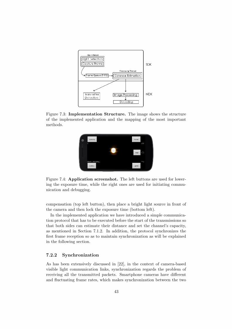
Figure 7.3: Implementation Structure. The image shows the structureof the implemented application and the mapping of the most importantmethods.
Figure 7.4: Application screenshot. The left buttons are used for lower-ing the exposure time, while the right ones are used for initiating commu-nication and debugging.
compensation (top left button), then place a bright light source in front ofthe camera and then lock the exposure time (bottom left).
In the implemented application we have introduced a simple communica-tion protocol that has to be executed before the start of the transmissions sothat both sides can estimate their distance and set the channel’s capacity,as mentioned in Section 7.1.2. In addition, the protocol synchronizes thefirst frame reception so as to maintain synchronization as will be explainedin the following section.
7.2.2 Synchronization
As has been extensively discussed in [22], in the context of camera-basedvisible light communication links, synchronization regards the problem ofreceiving all the transmitted packets. Smartphone cameras have differentand fluctuating frame rates, which makes synchronization between the two
43
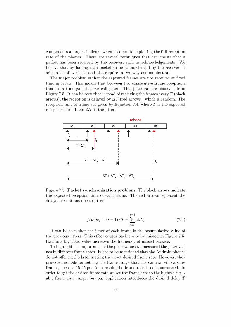
components a major challenge when it comes to exploiting the full receptionrate of the phones. There are several techniques that can ensure that apacket has been received by the receiver, such as acknowledgements. Webelieve that by having each packet to be acknowledged by the receiver, itadds a lot of overhead and also requires a two-way communication.
The major problem is that the captured frames are not received at fixedtime intervals. This means that between two consecutive frame receptionsthere is a time gap that we call jitter. This jitter can be observed fromFigure 7.5. It can be seen that instead of receiving the frames every T (blackarrows), the reception is delayed by ∆T (red arrows), which is random. Thereception time of frame i is given by Equation 7.4, where T is the expectedreception period and ∆T is the jitter.
Figure 7.5: Packet synchronization problem. The black arrows indicatethe expected reception time of each frame. The red arrows represent thedelayed receptions due to jitter.
framei = (i− 1) · T +
i−1∑n=1
∆Tn (7.4)
It can be seen that the jitter of each frame is the accumulative value ofthe previous jitters. This effect causes packet 4 to be missed in Figure 7.5.Having a big jitter value increases the frequency of missed packets.
To highlight the importance of the jitter values we measured the jitter val-ues in different frame rates. It has to be mentioned that the Android phonesdo not offer methods for setting the exact desired frame rate. However, theyprovide methods for setting the frame range that the camera will captureframes, such as 15-25fps. As a result, the frame rate is not guaranteed. Inorder to get the desired frame rate we set the frame rate to the highest avail-able frame rate range, but our application introduces the desired delay T
44

between the frame receptions. For example, in order to get 2fps we manuallydelay each reception for 500ms. The results are summarized in Table 7.1.
Table 7.1: Jitter measurements for different fps. For each frame ratewe measured the jitter of 100 consecutive frames.
Frame Rate (fps) Mean Jitter (ms) Max Jitter (ms)
1 7 22
2 6 19
5 7.5 63
10 58 154
It can be observed that as we increase the frame rate the jitter increases.This means that as the frame rate increases, we will experience more missedpackets. As a consequence, we need a way to reduce the packet misses inorder to receive all the transmitted packets. In other words, we need tomake the red arrows, of Figure 7.5, go as close to black ones, that indicatethe expected reception rate. For example, for a frame rate of 2fps, instead ofreceiving each packet at a period of 500ms we can reduce it by X, as shownin Equation 7.5.
delay = T −X (7.5)
The problem that still remains is selecting the value of X. We assumethat the jitter values follow a random distribution. Therefore, we choose tocalculate X as the expected value of the jitter values. Equation 7.6 showsthe calculation of the expected value for a given distribution of jitter valuesvi, where pi is the probability of value i.
E[∆T ] =
k∑n=1
pn · vn (7.6)
After applying the above analysis we expect that the frame reception timeswill oscillate around the value of period T . As a result, the reception timejitter will not keep increasing in every new frame reception. Each packet isrepeated by the transmitter for a specific amount of time which is the periodT of the reception rate. Furthermore, we make sure that each frame captureoccurs approximately at the middle of the transmitter packet. Based onthat and the fact that a whole packet can be decoded from a single framewe can estimate the channel’s data rate. For example, if the packet size is 8symbols and the reception rate is 1fps, then the data rate is 8 symbols persecond, which corresponds to 0.5 bytes per second.
In order to synchronize the initial transmission, so that all the rest willcome “around” period T , we utilize the light sensor of the phone. Themain reason is that we want the two components to have a common time
45
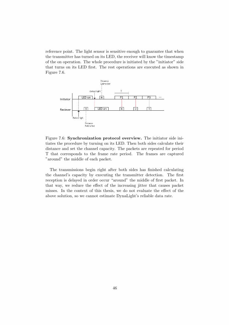
reference point. The light sensor is sensitive enough to guarantee that whenthe transmitter has turned on its LED, the receiver will know the timestampof the on operation. The whole procedure is initiated by the ”initiator” sidethat turns on its LED first. The rest operations are executed as shown inFigure 7.6.
Figure 7.6: Synchronization protocol overview. The initiator side ini-tiates the procedure by turning on its LED. Then both sides calculate theirdistance and set the channel capacity. The packets are repeated for periodT that corresponds to the frame rate period. The frames are captured”around” the middle of each packet.
The transmissions begin right after both sides has finished calculatingthe channel’s capacity by executing the transmitter detection. The firstreception is delayed in order occur “around” the middle of first packet. Inthat way, we reduce the effect of the increasing jitter that causes packetmisses. In the context of this thesis, we do not evaluate the effect of theabove solution, so we cannot estimate DynaLight’s reliable data rate.
46
Chapter 8
Evaluation
In this chapter we present the evaluation of the developed system. In Sec-tion 8.1, we present all the experiments that refer to way that DynaLightadjusts its channel capacity based on the detected distance as explained inSection 7.1. We continue our evaluation on the implemented decoding imageprocessing pipeline that was presented in Section 6.2.2. The evaluation ofthe decoding regards the avoidance of the over-exposure effect, the impactof ambient light, as well as, its real-time performance.
For evaluation we utilized smartphone application that was explained inSection 7.2. The application was mainly used in order capture and save theframes to be evaluated. In order to be able to repeat our experiments wecreated Python scripts that execute the same image processing code as in thesmartphone. In that way we could evaluate and improve our implementedmethods offline. For example, we could capture several frames and processthem offline and get the same results as running on the smartphone device.
8.1 Adapting to Variable Distance
In this section we compare our transmitter detection method, that waspresented in Section 6.2.1, with the one that was presented in Luxapose[21]. Recall that we improved the existing methods by adding a contrastincrease step. We show the impact on the detected blob size with respect tothe amount of information we can fit in every frame. Moreover, we evaluatethe impact of the selected diffuser lens.
8.1.1 Blob Size vs Distance
Methodology
We begin by evaluating the importance of using a diffuser lens. We usedthe diffuser lens to reduce the viewing angle of the LED from 110 to 20 .This results in having a more narrow and directed light beam but also a
47

brighter light source, due to the fact that the light is diffused. We comparethe performance of the Luxapose transmitter detection in the case of usingor not the lens.
Furthermore, we evaluate our own improvement in the detection mechan-ism that was presented in Section 6.2.1. The evaluation is done in 9 differentpositions of varying distance from 20cm to 120cm. For each position, wecaptured 50 frames and averaged the detected transmitter radius.
It has to be clarified that when we refer to the Luxapose, we refer tothe transmitter detection method that was presented in [21], without ouraddition. In DynaLight, we use both the diffuser lens and the contrastincrease.
As has been mentioned above we perform the blob detection when thelight is turned fully on and without modulating.
Results
The results of our experiments can be found in Figure 8.1.
Observation 1 Using the diffuser lens increases the detected blob by 50% inthe close distances, while the contrast increase further increases the detectedblob by 40%.
The results of these experiments highlight the importance of using a lens.It can be observed that light diffusion increases the brightness of the trans-mitted light resulting in greater blob.
Furthermore, we can observe that using the contrast increase step beforeperforming the transmitter detection increases the detected light approxim-ately 40% on average. Increasing the image’s contrast proves that it canreveal information that could be “hidden” due to the low exposure settings.Furthermore, by using both the lens and the additional image processingstep also results in being able to detect a 20% bigger blob in the distanceof 120cm. This means that our additions have increased the coverage of oursystem.
Observation 2 The blob size is not proportional to the square of the dis-tance between the transmitter and receiver.
The relation of the blob size and the distance does not follow the inversesquare law. However, the behavior is similar, meaning that it drops expo-nentially. This is because we are not directly measuring the emitted powerfrom the light source. We believe that this phenomenon is caused by sev-eral parameters of the image processing that measures the blob size. Morespecifically, the used transmitter detection method blurs the image beforemeasuring the transmitter blob. As a result, we are not measuring the trans-mitter’s size but the light “aura” that it creates. The created light “aura”
48

is more noticeable in the closer distances and that is why the improvementof the contrast increase is higher. As the distance increases and due to thelow exposure time the “aura” fades away. This phenomenon in the closerdistances may also be amplified by the camera’s protective lens that mayintroduce additional reflections.
Figure 8.1: Blob size vs Distance. The red and blue lines refer to thetransmitter detection method presented in Luxapose [21]. The green lineregards DynaLight, that uses both the diffuser and the contrast increase.
8.1.2 Number of Symbols vs Distance
Methodology
After showing the impact of the diffurer and contrast increase in the sizeblob size we continue our evaluation on the number of symbols that can fitin the detected blob for both DynaLight and Luxapose. The calculation ofthe number of symbols is done as explained in Section 7.1.2, excluding thepreamble symbols.
For the evaluation we used the same captured frames as in the previousexperiment. After detecting the blob size we calculate the number of symbolsthat can fit in the detected blob. It has to be mentioned that we performthis evaluation using the diffuser lens in both Luxapose and DynaLight.
Results
The behavior in Figure 8.2 is similar to the previously explained figure asexpected. The increase in the number of symbols is more noticeable in thecloser distances where the detected blob is bigger. The positive observation
49

is that at the distance of 120cm we can still transmit 2 symbols per packet.Moreover, at the distance of 90cm we can transmit 50% more data comparedto Luxapose. Recall that the number of symbols in the figure refers to thenumber of symbols that we can definitely decode from a single frame, asexplained in Section 7.1.2.
However, it is noticeable that the amount of symbols does not decreaselinearly after the distance of 60cm. This is mainly caused by the fact thatthe detected blob decreases but is still “large” enough to include the sameamount of symbols.
Figure 8.2: Number of symbols vs Distance. We get 40% more symbolson average, compared to Luxapose.
8.1.3 DynaLight’s Adaptive Channel Capacity
In this section we evaluate the influence of the proposed channel capacityadaptation that was presented in Section 7.1.2. Recall that in the state-of-the-art systems the channel capacity is fixed. Having a dynamic channelcapacity increases the flexibility of the implemented system when it comesto operating in different distances.
Methodology
The goal of the three evaluation experiments that we conducted is to high-light the importance of adapting the channel capacity based on the distancebetween the transmitter and the receiver. In order to achieve that, we evalu-ate our system in 3 different distances, 20cm, 60cm and 90cm. The distanceswere chosen so that we fit 16, 8 and 4 symbols accordingly (excluding the
50
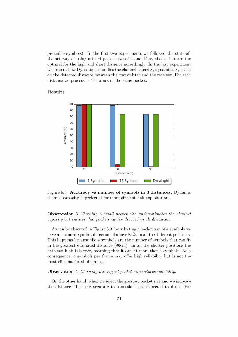
preamble symbols). In the first two experiments we followed the state-of-the-art way of using a fixed packet size of 4 and 16 symbols, that are theoptimal for the high and short distance accordingly. In the last experimentwe present how DynaLight modifies the channel capacity, dynamically, basedon the detected distance between the transmitter and the receiver. For eachdistance we processed 50 frames of the same packet.
Results
Figure 8.3: Accuracy vs number of symbols in 3 distances. Dynamicchannel capacity is preferred for more efficient link exploitation.
Observation 3 Choosing a small packet size underestimates the channelcapacity but ensures that packets can be decoded in all distances.
As can be observed in Figure 8.3, by selecting a packet size of 4 symbols wehave an accurate packet detection of above 85%, in all the different positions.This happens because the 4 symbols are the number of symbols that can fitin the greatest evaluated distance (90cm). In all the shorter positions thedetected blob is bigger, meaning that it can fit more that 4 symbols. As aconsequence, 4 symbols per frame may offer high reliability but is not themost efficient for all distances.
Observation 4 Choosing the biggest packet size reduces reliability.
On the other hand, when we select the greatest packet size and we increasethe distance, then the accurate transmissions are expected to drop. For
51
example in the 60cm we cannot fit more than 8 symbols, which reducesthe probability of correct reception. However, we see that very few packetswere decoded properly. This can be explained by the fact that in the 60cmdistance the detected blob is big enough to fit 8 symbols. Recall that ourcalculations are based on including each packet twice in the detected blob(Figure 7.2). As a result, there is a small chance that the 16bits are perfectlyaligned and fit the detected blob radius. Furthermore, decoding is impossiblein the highest evaluating distance because the blob size is too small to fitthe total of 16 symbols.
Observation 5 DynaLight’s channel capacity adaptation ensures efficientchannel utilization along with an accuracy above 85%.
We show that by modifying the channel capacity we can achieve an ac-curacy above 85% in all individual distances. As we can observe from theresults, as we move away from light source the accuracy drops. We believethat having an accuracy of 100% is impossible due to numerous factors thatinfluence our system. The basic reason is the image processing pipelinethat introduces noise in high distances (mostly by thresholding method).Moreover, as we move away from light source there is a high probabilitythat the camera sensor will introduce additional noise. This means thatsome pixels might not be saturated the same way as in the closer distances,which may affect our decoding performance.
8.2 Decoding
In this section we evaluate the decoding pipeline that was presented in Sec-tion 6.2.2. We begin by evaluating the which methods offers the best resultsin avoiding the over-exposure effects. Then, we show how robust DynaLightis to ambient light. Finally, we discuss its real time performance.
8.2.1 Overcoming Over-exposure Effects
Methodology
We begin by comparing the decoding methods (pixels selection) with re-spect to the one used in Luxapose (middle column), in order to see whichmethod has the highest decoding accuracy. We chose to evaluate the decod-ing method in the distance of 40cm where we can fit 8 symbols. We eval-uate our methods using 3 different packets 1) “01010101”, 2) “01011001”and 3) “10100101”. Packets 2 and 3 have two consecutive identical symbolscompared to packet 1. Evaluating packets 2 and 3 will highlight possiblelimitations that are introduced by the over-exposure effect.
For each packet we captured and decoded 50 frames. We relate the accur-acy of each method in terms of how many times the packet was accurately
52
decoded. If the decoded symbol sequence is different or has a different lengththen we consider a false decoding.
Results
Observation 6 The over-exposure effect is more observable in the center ofthe blob, therefore, we cannot accurately decode data from the middle columnof the blob.
It can be clearly seen from Figure 8.4 that the pixel selection methodused in Luxapose cannot be applied in our case. The over-exposure effectintroduces too much noise in the signal. When it comes to the second pixelselection method, we can observe that it dramatically increases the accuratedecoding but the percentage differs between the packets. We conclude thatthe middle column of the blob may contain the most bright signal but thisfact increases the over-exposure effect. This can be clearly observed in thecase of packet 3 where the two consecutive 0 symbols can not be accuratelydecoded. Recall that the over-exposure effect tends to enlarge the size of thewhite bands. In the case of packet 3, there are cases where the white bandsappear bigger than the expected ones, resulting in false decoding. The thirdpixel selection shows that it offers the best option with an accuracy of morethan 90%. Moreover, these experiments showed the importance of having anautomatic offset selection mechanism, as in the second method. The closerto the vertical radius column, the more over-exposure noise the signal willexperience. On the other hand, a high offset value may also lead to falsedecoding, due to the fact that the farther away we go from the center oflight source, the noisy the signal can get.
8.2.2 Influence of Ambient Light
In this section we evaluate the impact of ambient light with respect to accur-ate decoding. Since we did not have a light sensor, we created three differentexperiment conditions by changing the amount of light in the experimentsroom. In the first case there is no ambient light in the room. In the secondcase we turned on half of the room’s ceiling lights, as depicted in Figure8.5. In the third case, we turned on all the room’s ceiling lights and usedan additional light source (lamp) right above the VLC link, as shown inFigure 8.6. As in the previous experiments we capture 50 frames for everyindividual experiment.
Methodology
We evaluate the impact of ambient light in 40cm and 90cm. The two dis-tances were selected based on the number of symbols that can be fitted,
53

Figure 8.4: Accuracy of different pixel selection methods using3 different symbol combinations. Packet1= “01010101”, Packet2=“01011001” and Packet3= “10100101”. Above the figure we show a simplerepresentation of each method, similar to Figure 6.4.
namely 8 and 4 accordingly (excluding preamble symbols). In the first ex-periment we wanted to show the impact of ambient light in the least accuratepacket of the previous section, which was packet 3, believing that ambientlight will amplify the over-exposure effects. In the second experiment weused two slightly different packets 4) “0110” and 5) “1001” (similar to pre-vious section), that can show the impact of ambient light as well as theover-exposure effect on the decoding.
Results
Observation 7 Ambient light does not affect our system significantly inboth short and great distances, due to low exposure settings.
As can be seen from Figures 8.7 and 8.8, there is no significant impact onthe decoding accuracy introduced by the ambient light in both cases. Webelieve that this is caused by the low exposure settings that enable only verybright light to be visible in the captured image. This observation highlights
54

Figure 8.5: Low ambient light setup. Half of the ceiling lights are on.
Figure 8.6: High ambient light setup. All of the ceiling lights are onplus a lamp pointing above the VLC link.
the benefit of using camera sensors instead of photodiodes or LEDs, whereexternal light sources introduce unavoidable noise. Nevertheless, we believethat the ambient light that we introduced is not that bright compared tothe light of the transmitter. However, having multiple concurrent transmit-ters operating at the same light intensity will definitely affect the systemsperformance with respect to introducing noise.
Finally, we observe a slight drop in the accuracy as the distance increases.This can be observed in packets 4 and 5 that are evaluated in a higherdistance. This fact is similar to Figure 8.3, and is mostly caused by noisethat is introduced by the image processing methods.
55

Figure 8.7: Accuracy vs ambient light for Packet3 in 40cm. Noimpact is observed in close distances.
Figure 8.8: Accuracy vs ambient light in 90cm. Packet4= “0110”and Packet5= “1001”. No significant impact is observed even in the largedistance.
56

8.2.3 Execution Time
Compared to the Luxapose project, all the decoding algorithms of Dyna-Light are executed locally in the device. We measured the real-time per-formance of our decoding algorithm, so as to identify which are the mosttime consuming methods. However, since we are not using a high-end devicewe have noticed that the decoding time varies.
The average decoding time for decoding a single frame varies from 1 to 2seconds. However, there are times that the decoding time drops to 600ms,which may be caused by the scheduling mechanisms of the Android OS.We further experimented with changing the scheduling priority of the pro-cessing thread to the maximum available by the operating system. However,increasing a thread’s priority proved to reduce the processing time of thedecoding slightly, but it introduced additional jitter to the reception of theframes. We believe that the additional delay is caused by the fact that theprocessing thread gets a similar priority with the camera’s capturing thread,that provides the captured frames. As a result, we believe that the schedul-ing mechanism of the operating system is sharing the CPU between the highpriority threads, including the processing thread. We believe that we canobtain better performance by using a more powerful device with respect toprocessing power.
In addition, we noticed that the OpenCV methods require lots of pro-cessing power and memory. The most time consuming methods are the con-trast increase and the adaptive thresholding. As a result, we believe thatthere is room for improvement when it comes to improving the efficiency ofthe image processing techniques.
57

58
Chapter 9
Conclusions
9.1 Conclusions
Recent research has focused on creating high-rate visible light communic-ation links. Camera-based VLC has shown that it offers a great potentialwith respect to applicability, due to the fact that LED lighting and smart-phones are widely utilized. However, the existing VLC systems assume afixed distance between the transmitters and the receivers. Moreover, build-ing a universal camera-based VLC link is not considered an easy task dueto wide diversity of the hardware capabilities of the smartphones. The mostdemanding challenge is synchronizing the transmissions and the receptions.The problem is caused by the unstable frame rate of the smartphone cam-eras. Therefore, any camera-based communication link may suffer fromdynamic losses.
In this thesis, we highlight the need for an flexible visible light commu-nication link that will dynamically adjust its channels capacity based onthe distance between the transmitter and the receiver. Based on that, wepresent DynaLight, an adaptive VLC system for smartphones. Our systemis able to estimate the distance between the transmitter and the receiver andmodify its channel capacity. This results in an efficient channel utilizationin different distances.
Furthermore, by applying an image processing enhancement we managedto improve the transmitter detection mechanism, that was presented in arecent related work, by 40%, meaning that we increased the feasible channelcapacity of our link. In addition, we identified and avoided effects that arecaused by the limited camera control of low cost smartphones.
Finally, we developed a smartphone application that implements our solu-tions. During our work we experienced the two main problems of synchron-ization, which refer to the mixed and missed packet problems, that are intro-duced by the fluctuating reception rate. We avoid the mixed packet problemby making sure that from each captured frame a complete packet can be de-
59

coded. As a result, the system’s reliability depends on synchronizing thepacket’s reception. We believe that our observations and contributions willinfluence other related projects that will take advantage of the potentialsthat the visible light offers in creating communication links.
9.2 Future Work
In the context of this thesis we did not fully evaluate our proposed solutionfor the reception synchronization. We observed that our solution has theability to reduce the effect of the reception jitter and enable us to furtherimprove the link’s data rate. By further studying the behavior of the jitterwe may be able to predict the next frame reception or better understandthe causes of reception rate fluctuation. Furthermore, the phone can con-tinuously monitor the distribution of the jitter values, so as to recalculatethe expected values that are used to reduce the influence of the jitter in-crease. In that way, the phone can dynamically adjust to the fluctuation ofthe frame rate.
Our system is robust to ambient light and this caused by the low ex-posure settings. We believe that utilizing more than one transmitters willintroduce errors in the decoding because the different bands will collide. Webelieve that by utilizing different light colors might be a decent alternativefor separating transmissions. However, this implies that the whole imageprocessing pipeline has to be reconsidered and modified so as to support“colored” VLC transmissions.
When it comes to further improvements of the current setup, we believethat DynaLight’s performance can increase notably by utilizing a more re-cent smartphone. Being able to execute the image processing pipeline fasterwill also enable DynaLight to cope with mobility. This means that trans-mitter detection could be executed real-time, along with the decoding, so asto monitor if the transmitter has changed its position.
With respect to improvements to the detection and decoding process, webelieve that OpenCV methods introduce overhead that could be avoided byimplementing methods such as thresholding. A further improvement wouldbe to also crop the detected transmitter area and process it individually inorder to reduce the computation overhead and memory requirements.
60
Appendix A
Transmitter Experiments
A.1 Android Limitations
One of the initial goals of this project was to create an application thatcould use commercial hardware to create simple VLC links. Smartphonesare already equipped with LEDs that could be used in creating VLC links.In the first phase of this project we experimented with the phone’s flashlight to check if it can be toggled in such a high rate that could be used inour project. We concluded that this is not an option due to the fact that theAndroid operating system does not offer much flexibility when it comes tomodulating the LED in high frequencies. More specifically, we observed anerratic behavior on the on off pattern when the LED was modulating fasterthan 5-7 Hz. We believe that this is mainly caused by the Android Javalayer that does not enable real-time operations. There are several real-timepatches that could be applied to the kernel of the Android OS but it is ratherimpractical and out of the scope of the current thesis. We also investigatedusing native code to access the LED but to the best of our knowledge, thereis no existing API that could support such operation. Thus, utilizing thedevice’s LED is not as trivial as one might consider.
A.2 External Flash Light
One of the initial motivations of the project was to create a commercialapplication that will enable smartphones to create flexible visible light com-munication links. Therefore, we created collaboration with the companythat produces the external flash Iblazr [5] (version 1). This device oper-ates via the audio jack of the smartphone. By using stereophonic audiosignal we were able to control the behavior of the light. Nevertheless, wecould not reach more than a few hundreds of Hz which again is too limited.We discussed with the engineers, that created the device, and came to theconclusion that the problem was caused by the existing firmware that was
61
running on the device, since it was designed as an external flash light andnot as a VLC component. However, the new version of Iblazr extends itscapabilities in terms of connectivity and programmability. It can be con-trolled via Bluetooth and supports firmware flash. We believe it could assistin creating commercial multi-transmitter VLC links but is something thatfurther needs to be investigated.
Based on the above facts, we decided to offload the LED modulation to amicrocontroller (Arduino).
62
Bibliography
[1] Arduino MEGA ADK. http://www.arduino.cc/en/Main/
ArduinoBoardMegaADK. [Online, Accessed May-2015].[2] ByteLight. http://www.bytelight.com/. [Online, Accessed November-2015].[3] Diffuser Lens LM1 for Cree MC-E Datasheet. https://www.maritex.com.
pl/media/uploads/products/op/LEDIL-LM1.pdf. [Online, Accessed June-2015].
[4] Disney Research on Visible Light Communication. http://www.
disneyresearch.com/project/visible-light-communication/. [Online,Accessed April-2015].
[5] Iblazr. http://iblazr.com/. [Online, Accessed April-2015].[6] MAX3421E. https://www.maximintegrated.com/en/products/
interface/controllers-expanders/MAX3421E.html. [Online, AccessedApril-2015].
[7] MOSFET IRL1004 Datasheet. http://www.irf.com/product-info/
datasheets/data/irl1004.pdf. [Online, Accessed October-2015].[8] NPN Switching Transistor 2N3904 Datasheet. https://www.sparkfun.com/
datasheets/Components/2N3904.pdf. [Online, Accessed October-2015].[9] pureLiFi. http://purelifi.com/. [Online, Accessed November-2015].
[10] XLamp MC-E. http://www.cree.com/LED-Components-and-Modules/
Products/XLamp/Arrays-Directional/XLamp-MCE. [Online, Accessed May-2015].
[11] Christos Danakis, Mostafa Afgani, Gordon Povey, Ian Underwood, and HaraldHaas. Using a cmos camera sensor for visible light communication. In GlobecomWorkshops (GC Wkshps), 2012 IEEE, pages 1244–1248. IEEE, 2012.
[12] Hany Elgala, Raed Mesleh, and Harald Haas. Indoor broadcasting via whiteleds and ofdm. Consumer Electronics, IEEE Transactions on, 55(3):1127–1134, 2009.
[13] Domenico Giustiniano, Nils Ole Tippenhauer, and Stefan Mangold. Low-complexity visible light networking with led-to-led communication. In WirelessDays (WD), 2012 IFIP, pages 1–8. IEEE, 2012.
[14] J Grubor, OC Jamett, JW Walewski, S Randel, and K-D Langer. High-speed wireless indoor communication via visible light. ITG-Fachbericht-Breitbandversorgung in Deutschland-Vielfalt fur alle?, 2007.
[15] Jelena Grubor, Sian Chong Jeffrey Lee, Klaus-Dieter Langer, Ton Koonen,and Joachim W Walewski. Wireless high-speed data transmission with phos-phorescent white-light leds. ECOC 2007, 2007.
[16] Tian Hao, Ruogu Zhou, and Guoliang Xing. Cobra: color barcode streamingfor smartphone systems. In Proceedings of the 10th international conferenceon Mobile systems, applications, and services, pages 85–98. ACM, 2012.
63

[17] Harald Haas. High-speed wireless networking using visible light. https://
spie.org/x93593.xml. [Online, Accessed November-2015].[18] Wenjun Hu, Jingshu Mao, Zihui Huang, Yiqing Xue, Junfeng She, Kaigui
Bian, and Guobin Shen. Strata: layered coding for scalable visual communic-ation. In Proceedings of the 20th annual international conference on Mobilecomputing and networking, pages 79–90. ACM, 2014.
[19] Lennart Pieter Klaver. Design of a network stack for directional visible lightcommunication. ratio, 3:4, 2014.
[20] Toshihiko Komine and Masao Nakagawa. Fundamental analysis for visible-light communication system using led lights. Consumer Electronics, IEEETransactions on, 50(1):100–107, 2004.
[21] Ye-Sheng Kuo, Pat Pannuto, Ko-Jen Hsiao, and Prabal Dutta. Luxapose:Indoor positioning with mobile phones and visible light. In Proceedings of the20th annual international conference on Mobile computing and networking,pages 447–458. ACM, 2014.
[22] Hui-Yu Lee, Hao-Min Lin, Yu-Lin Wei, Hsin-I Wu, Hsin-Mu Tsai, and KateChing-Ju Lin. Rollinglight: Enabling line-of-sight light-to-camera communic-ations. In Proceedings of the 13th Annual International Conference on MobileSystems, Applications, and Services, pages 167–180. ACM, 2015.
[23] Liqun Li, Pan Hu, Chunyi Peng, Guobin Shen, and Feng Zhao. Epsilon:A visible light based positioning system. In 11th USENIX Symposium onNetworked Systems Design and Implementation (NSDI 14), pages 331–343.USENIX Association, 2014.
[24] Edmundo Monteiro and Steve Hranilovic. Constellation design for color-shiftkeying using interior point methods. In Globecom Workshops (GC Wkshps),2012 IEEE, pages 1224–1228. IEEE, 2012.
[25] Edmundo Monteiro and Steve Hranilovic. Design and implementation of color-shift keying for visible light communications. Lightwave Technology, Journalof, 32(10):2053–2060, 2014.
[26] Niranjini Rajagopal, Patrick Lazik, and Anthony Rowe. Visual light land-marks for mobile devices. In Proceedings of the 13th international symposiumon Information processing in sensor networks, pages 249–260. IEEE Press,2014.
[27] Sridhar Rajagopal, Richard D Roberts, and Sang-Kyu Lim. Ieee 802.15. 7 vis-ible light communication: modulation schemes and dimming support. Com-munications Magazine, IEEE, 50(3):72–82, 2012.
[28] Richard D Roberts. Undersampled frequency shift on-off keying (ufsook) forcamera communications (camcom). In Wireless and Optical CommunicationConference (WOCC), 2013 22nd, pages 645–648. IEEE, 2013.
[29] Stefan Schmid, Giorgio Corbellini, Stefan Mangold, and Thomas R Gross.Led-to-led visible light communication networks. In Proceedings of the four-teenth ACM international symposium on Mobile ad hoc networking and com-puting, pages 1–10. ACM, 2013.
[30] Yuichi TANAKA, Toshihiko Komine, Shinichiro Haruyama, and Masao Nak-agawa. Indoor visible communication utilizing plural white leds as lighting.In Personal, Indoor and Mobile Radio Communications, 2001 12th IEEE In-ternational Symposium on, volume 2, pages F–81. IEEE, 2001.
[31] Qing Wang and Domenico Giustiniano. Communication networks of visiblelight emitting diodes with intra-frame bidirectional transmission. In Proceed-ings of the 10th ACM International on Conference on emerging NetworkingExperiments and Technologies, pages 21–28. ACM, 2014.
64

[32] Qing Wang, Domenico Giustiniano, and Daniele Puccinelli. An open sourceresearch platform for embedded visible light networking. Wireless Commu-nications, IEEE, 22(2):94–100, 2015.
[33] Grace Woo, Andrew Lippman, and Ramesh Raskar. Vrcodes: Unobtrusiveand active visual codes for interaction by exploiting rolling shutter. In Mixedand Augmented Reality (ISMAR), 2012 IEEE International Symposium on,pages 59–64. IEEE, 2012.
[34] Zhice Yang, Zeyu Wang, Jiansong Zhang, Chenyu Huang, and Qian Zhang.Wearables can afford: Light-weight indoor positioning with visible light. InProceedings of the 13th Annual International Conference on Mobile Systems,Applications, and Services, pages 317–330. ACM, 2015.
65