dynamic analysis of piston secondary motion for small reciprocating compressors
TRANSCRIPT
w innce,
r. Thediallessthe
essorinderf theallyThectionrre-
istonachdis-
n ofe waseffectshe oilhe pin
Downloaded F
A. T. Pratae-mail: [email protected]
J. R. S. Fernandes
Department of Mechanical Engineering,Federal University of Santa Catarina,
88040-900 Florianopolis,SC-Brazil
F. FagottiBrazilian Compressor Industry—EMBRACO,
89219-901 Joinville,SC-Brazil
Dynamic Analysis of PistonSecondary Motion for SmallReciprocating CompressorsPiston dynamics plays a fundamental role in two critical processes related to fluid floreciprocating compressors. The first is the gas leakage through the radial clearawhich may cause considerable loss in the pumping efficiency of the compressosecond process is the viscous friction associated with the lubricant film in the raclearance. In the present contribution a numerical simulation is performed for a ringpiston inside the cylinder of a reciprocating compressor, including both the axial andradial piston motion. The compressor considered here is a small hermetic compremployed in domestic refrigerators, with the radial clearance between piston and cylfilled with lubricant oil. In operation, the piston moves up and down along the axis ocylinder, but the radial oscillatory motion in the cylinder bore, despite being ususmall, plays a very important role on the compressor performance and reliability.compromise between oil leakage through the piston-cylinder clearance and the frilosses requires a detailed analysis of the oscillatory motion for a good design. All cosponding forces and moments are included in the problem formulation of the pdynamics in order to determine the piston trajectory, velocity and acceleration at etime step. The hydrodynamic force is obtained from the integration of the pressuretribution on the piston skirt, which, in turn, is determined from a finite volume solutiothe time dependent equation that governs the oil flow. A Newton-Raphson proceduremployed in solving the equations of the piston dynamics. The results explored theof some design parameters and operating conditions on the stability of the piston, tleakage, and friction losses. Emphasis was placed on investigating the influence of tlocation, radial clearance and oil viscosity on the piston dynamics.@S0742-4787~11!00301-8#
Keywords: Piston Dynamics, Ringless Piston, Piston Lubrication
n
mfi
r
n
fgluneaa
h
r
andy as.m-
re-urentalLi
ana--A
the
er-yhu
n,ofrma-re.en-
izelin-
a-elywnforop-
IntroductionThe forces acting on a piston as it goes up and down i
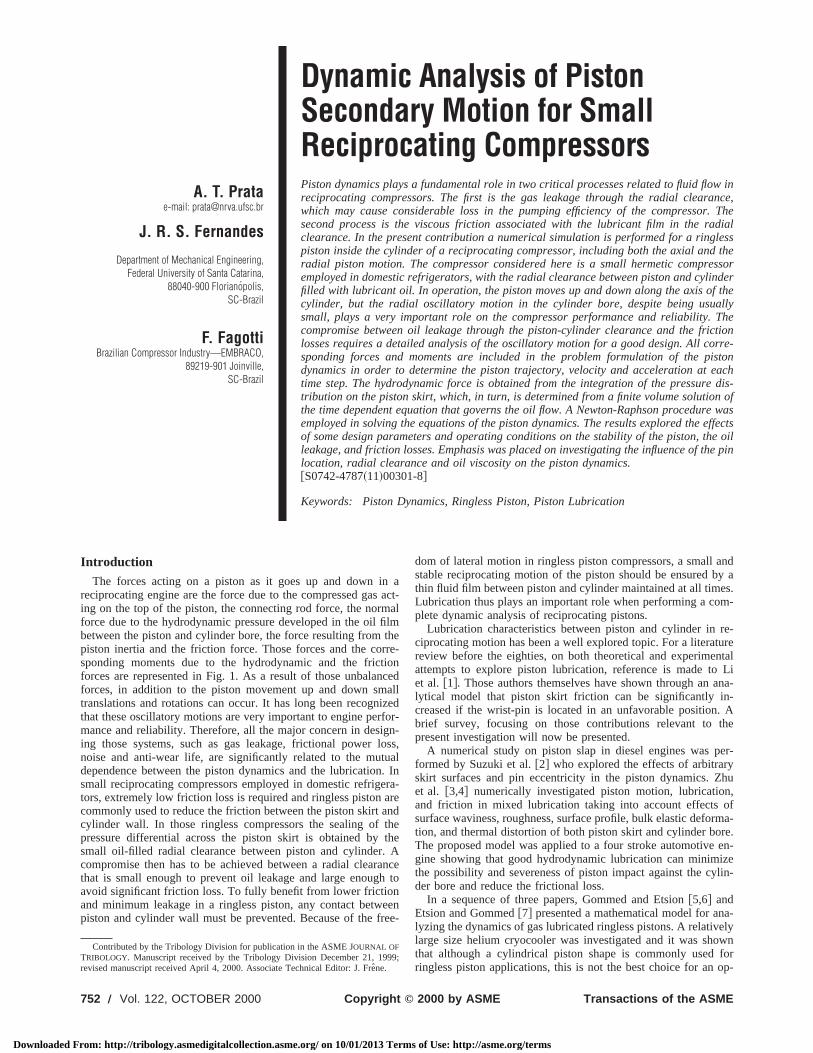
reciprocating engine are the force due to the compressed gasing on the top of the piston, the connecting rod force, the norforce due to the hydrodynamic pressure developed in the oilbetween the piston and cylinder bore, the force resulting frompiston inertia and the friction force. Those forces and the cosponding moments due to the hydrodynamic and the frictforces are represented in Fig. 1. As a result of those unbalaforces, in addition to the piston movement up and down smtranslations and rotations can occur. It has long been recognthat these oscillatory motions are very important to engine permance and reliability. Therefore, all the major concern in desiing those systems, such as gas leakage, frictional powernoise and anti-wear life, are significantly related to the mutdependence between the piston dynamics and the lubricatiosmall reciprocating compressors employed in domestic refrigtors, extremely low friction loss is required and ringless pistoncommonly used to reduce the friction between the piston skirtcylinder wall. In those ringless compressors the sealing ofpressure differential across the piston skirt is obtained bysmall oil-filled radial clearance between piston and cylinder.compromise then has to be achieved between a radial clearthat is small enough to prevent oil leakage and large enougavoid significant friction loss. To fully benefit from lower frictionand minimum leakage in a ringless piston, any contact betwpiston and cylinder wall must be prevented. Because of the f
Contributed by the Tribology Division for publication in the ASME JOURNAL OFTRIBOLOGY. Manuscript received by the Tribology Division December 21, 199revised manuscript received April 4, 2000. Associate Technical Editor: J. Freˆne.
752 Õ Vol. 122, OCTOBER 2000 Copyright ©
rom: http://tribology.asmedigitalcollection.asme.org/ on 10/01/2013 Term
aact-al
lmthere-ioncedallizedor-n-
oss,al. Inra-rend
thetheA
anceto
eenee-
dom of lateral motion in ringless piston compressors, a smallstable reciprocating motion of the piston should be ensured bthin fluid film between piston and cylinder maintained at all timeLubrication thus plays an important role when performing a coplete dynamic analysis of reciprocating pistons.
Lubrication characteristics between piston and cylinder inciprocating motion has been a well explored topic. For a literatreview before the eighties, on both theoretical and experimeattempts to explore piston lubrication, reference is made toet al. @1#. Those authors themselves have shown through anlytical model that piston skirt friction can be significantly increased if the wrist-pin is located in an unfavorable position.brief survey, focusing on those contributions relevant topresent investigation will now be presented.
A numerical study on piston slap in diesel engines was pformed by Suzuki et al.@2# who explored the effects of arbitrarskirt surfaces and pin eccentricity in the piston dynamics. Zet al. @3,4# numerically investigated piston motion, lubricatioand friction in mixed lubrication taking into account effectssurface waviness, roughness, surface profile, bulk elastic defotion, and thermal distortion of both piston skirt and cylinder boThe proposed model was applied to a four stroke automotivegine showing that good hydrodynamic lubrication can minimthe possibility and severeness of piston impact against the cyder bore and reduce the frictional loss.
In a sequence of three papers, Gommed and Etsion@5,6# andEtsion and Gommed@7# presented a mathematical model for anlyzing the dynamics of gas lubricated ringless pistons. A relativlarge size helium cryocooler was investigated and it was shothat although a cylindrical piston shape is commonly usedringless piston applications, this is not the best choice for an
9;
2000 by ASME Transactions of the ASME
s of Use: http://asme.org/terms
nh
rm
ea
l
t
ast
bfn
,
o
erfromllbe-orslas-th-
ro-sf
ttom
ingce
,id-
med
e
Downloaded F
timum design as far as piston stability and sealing performaare concerned. Other piston shapes were explored and anproved design was obtained with noncylindrical profiles.
Theoretical and experimental results were obtainedYamaguchi@8# for two piston-cylinder assemblies. One operatiin the standard mode, with hydrodynamic lubrication, and otoperating in hydrostatic lubrication with oil being injected in thradial clearance between piston and cylinder. It was shownlow crankshaft velocities, that the hydrostatic piston can opewith reduced friction and same oil leakage as the hydrodynapiston as long as the radial clearance is made small.
Lee @9# proposed a piston with tilted top for an internal combustion engine that is able to employ the combustion gas forcfavor of the piston stability. Elastohydrodynamic lubrication winvestigated by Dursunkaya et al.@10# for a diesel engine. It wasshown that surface deformation can play a significant role inpiston secondary motion.
Mixed lubrication between piston and cylinder in a hydraupiston pump-motor was investigated by Fang and Shirakashi@11#.The metal contact between the parts was expressed in termscontact ratio defined as the percentage of the period with conto the whole period of stroke. It was shown that curves of conratio versus the ratio of dynamic pressure due to wedge effecthe supply pressure in the cylinder are effective in expressingcharacteristics of mixed lubrication for this type of system.
Liu et al. @12# performed a mixed lubrication model forpiston-cylinder assembly and showed that a parabolic pistonprofile considerably reduces the friction power loss and substially improves lubrication in both the up and down strokes.
The present work deals with oil lubrication in ringless reciprcating compressors. The main objective here is to perform anamic analysis for the thin oil film between piston and cylinderpresence of oscillatory secondary motion occurring in smallfrigerating compressors. The complete set of equations describoth piston and connecting rod motion are employed in themulation, allowing the prediction of the spatial and time varyiradial clearance, required for the lubrication equation.
For the typical hermetic compressor being considered herebottom of the compressor shell is filled with oil and the shaft lavertically with its lower part immersed in the lubricant@13#. Dur-ing operation an helicoidal channel drives the oil along the shfrom the swamp to the top where the connecting rod is assembOil is then abundantly sprinkled at the cylinder wall, the pist
Fig. 1 Force and moments acting on a piston
Journal of Tribology
rom: http://tribology.asmedigitalcollection.asme.org/ on 10/01/2013 Term
nceim-
bygereforate
ic
-in
s
the
ic
of atactactt tothe
kirtan-
o-dy-inre-ing
or-g
theys
aftled.n
base, and the wrist-pin. Oil is also carried into the cylindthrough the compressor suction, because gas suction occursthe shell environment which is laden with small oil droplets. Athat assures a flooded lubrication within the radial clearancetween piston and cylinder. Visualizations made with compresshaving some of their parts fabricated with transparent thermoptic provided a further support for the flooded lubrication hypoesis assumed throughout the present analysis.
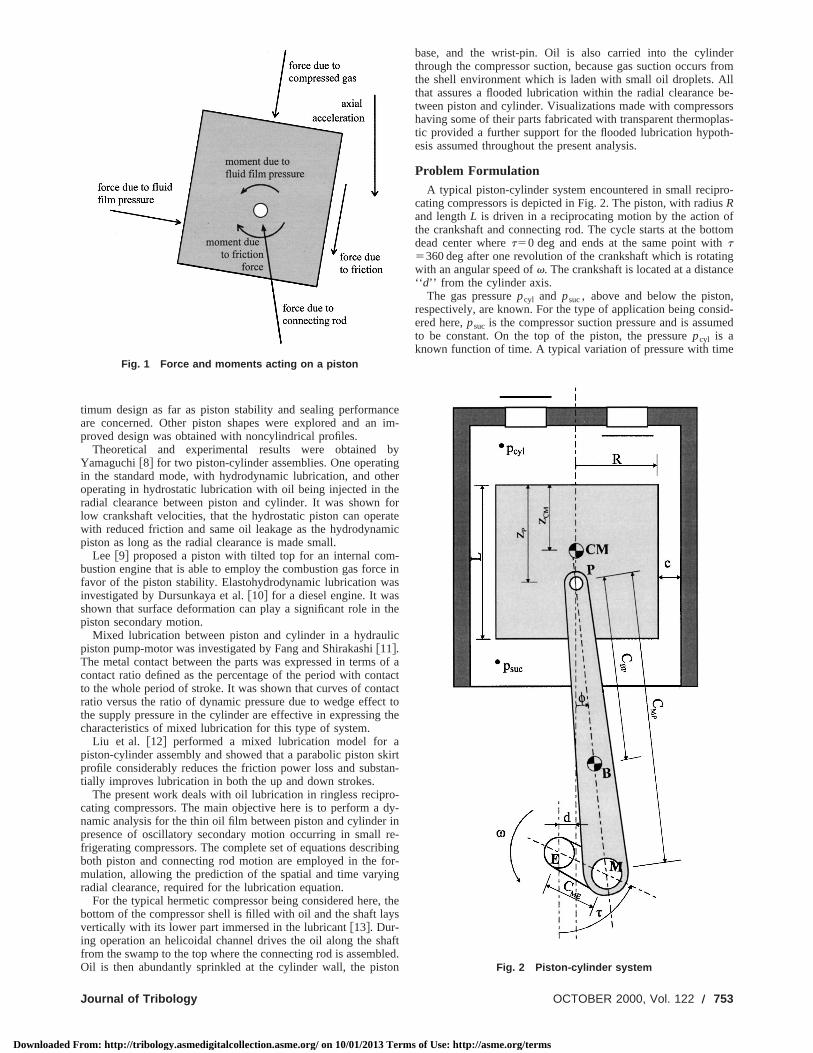
Problem FormulationA typical piston-cylinder system encountered in small recip
cating compressors is depicted in Fig. 2. The piston, with radiuRand lengthL is driven in a reciprocating motion by the action othe crankshaft and connecting rod. The cycle starts at the bodead center wheret50 deg and ends at the same point witht5360 deg after one revolution of the crankshaft which is rotatwith an angular speed ofv. The crankshaft is located at a distan‘‘ d’’ from the cylinder axis.
The gas pressurepcyl and psuc, above and below the pistonrespectively, are known. For the type of application being consered here,psuc is the compressor suction pressure and is assuto be constant. On the top of the piston, the pressurepcyl is aknown function of time. A typical variation of pressure with tim
Fig. 2 Piston-cylinder system
OCTOBER 2000, Vol. 122 Õ 753
s of Use: http://asme.org/terms
em
s
h
ssd
the
lv-
her
,
ure
siclear-, isres-re
ndstone a
a
Downloaded F
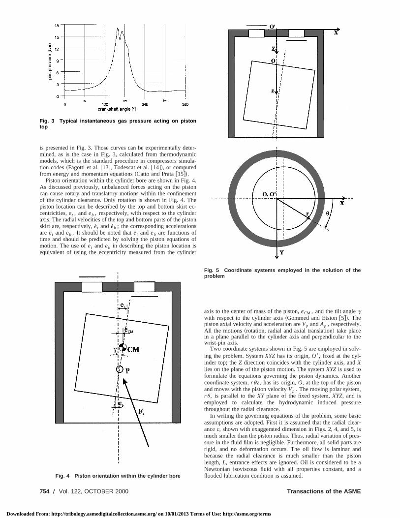
is presented in Fig. 3. Those curves can be experimentally dmined, as is the case in Fig. 3, calculated from thermodynamodels, which is the standard procedure in compressors simtion codes~Fagotti et al.@13#, Todescat et al.@14#!, or computedfrom energy and momentum equations~Catto and Prata@15#!.
Piston orientation within the cylinder bore are shown in Fig.As discussed previously, unbalanced forces acting on the pican cause rotary and translatory motions within the confinemof the cylinder clearance. Only rotation is shown in Fig. 4. Tpiston location can be described by the top and bottom skirtcentricities,et , andeb , respectively, with respect to the cylindeaxis. The radial velocities of the top and bottom parts of the pisskirt are, respectively,et and eb ; the corresponding accelerationare et and eb . It should be noted thatet andeb are functions oftime and should be predicted by solving the piston equationmotion. The use ofet andeb in describing the piston location iequivalent of using the eccentricity measured from the cylin
Fig. 3 Typical instantaneous gas pressure acting on pistontop
Fig. 4 Piston orientation within the cylinder bore
754 Õ Vol. 122, OCTOBER 2000
rom: http://tribology.asmedigitalcollection.asme.org/ on 10/01/2013 Term
ter-ic
ula-
4.tonente
ec-rtons
of
er
axis to the center of mass of the piston,eCM , and the tilt anglegwith respect to the cylinder axis~Gommed and Etsion@5#!. Thepiston axial velocity and acceleration areVp andAp , respectively.All the motions~rotation, radial and axial translation! take placein a plane parallel to the cylinder axis and perpendicular towrist-pin axis.
Two coordinate systems shown in Fig. 5 are employed in soing the problem. SystemXYZhas its origin,O8, fixed at the cyl-inder top; theZ direction coincides with the cylinder axis, andXlies on the plane of the piston motion. The systemXYZ is used toformulate the equations governing the piston dynamics. Anotcoordinate system,ruz, has its origin,O, at the top of the pistonand moves with the piston velocityVp . The moving polar systemru, is parallel to theXY plane of the fixed system,XYZ, and isemployed to calculate the hydrodynamic induced pressthroughout the radial clearance.
In writing the governing equations of the problem, some baassumptions are adopted. First it is assumed that the radial cancec, shown with exaggerated dimension in Figs. 2, 4, and 5much smaller than the piston radius. Thus, radial variation of psure in the fluid film is negligible. Furthermore, all solid parts arigid, and no deformation occurs. The oil flow is laminar abecause the radial clearance is much smaller than the pilength,L, entrance effects are ignored. Oil is considered to bNewtonian isoviscous fluid with all properties constant, andflooded lubrication condition is assumed.
Fig. 5 Coordinate systems employed in the solution of theproblem
Transactions of the ASME
s of Use: http://asme.org/terms
Journ
Downloaded From: h
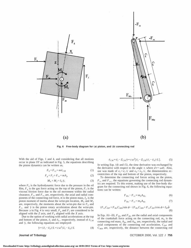
Fig. 6 Free-body diagram for „a… piston, and „b… connecting rod
n
i
i
y
-
on,m-dia-a-
ts
d
rod
With the aid of Figs. 1 and 4, and considering that all motiooccur in planeXY as indicated in Fig. 5, the equations describithe piston dynamics can be written as,
Fh1Frx5meCM (1)
Fg1F f1Frz5mAp (2)
Mh1M f5I Pg, (3)
whereFh is the hydrodynamic force due to the pressure in thefilm, Fg is the gas force acting on the top of the piston,F f is theviscous friction force due to the oil movement within the radclearance,Frz andFrx are, respectively, the axial and radial components of the connecting rod force,m is the piston mass,I p is thepiston moment of inertia about the wrist-pin location,Mh andM fare, respectively, the moments about the wrist-pin due toFh andF f , and g is the piston rotary acceleration about the wrist-pBecauseg in Fig. 4 is very small,Fg andF f are considered to bealigned with theZ axis, andFh aligned with theX axis.
Due to the option of working with radial accelerations at the tand bottom of the piston,et and eb , respectively, instead ofeCMand g, the following equations are employed:
g5~ et2eb!/L5cv2~ « t2 «b!/L (4)
al of Tribology
ttp://tribology.asmedigitalcollection.asme.org/ on 10/01/2013 Term
nsg
oil
al-
n.
op
eCM5et2ZCMg5cv2@ « t2ZCM~ « t2 «b!/L#. (5)
In writing Eqs.~4! and~5!, the time derivative was exchanged bthe derivative with respect to the anglet, wheredt5vdt. Also,use was made of« t5et /c and «b5eb /c, the dimensionless eccentricities of the top and bottom of the piston, respectively.
To determine the connecting rod forces acting on the pistFrx andFrz , the equations governing the connecting rod dynaics are required. To this extent, making use of the free-bodygram for the connecting rod shown in Fig. 6, the following equtions can be written:
FMx2Frx5mbABx (6)
FMz2Frz5mbABz (7)
~FrzCBP1FMzCMB!sinf2~FMxCMB1FrxCBP!cosf5I Bf(8)
In Eqs.~6!–~8!, FMx andFMz are the radial and axial componenof the crankshaft force acting on the connecting rod,mb is theconnecting rod mass,ABx andABz are, respectively, the radial anaxial components of the connecting rod acceleration,CBP andCMB are, respectively, the distance between the connecting
OCTOBER 2000, Vol. 122 Õ 755
s of Use: http://asme.org/terms
t
q
o
I
a
c
t
-uldat,
ltricalhaft-tionr
and
arch
are
inedueskirt,
oiled,
be-
tocal-thstimethe
imelgo-. Aednu-
he
theusne-ed
Downloaded F
center of mass toP and toM, as indicated in Fig. 6;f andf are,respectively, the connecting rod tilting angle with respect tocylinder axis and its angular acceleration;I B is the connecting rodmoment of inertia with respect to its center of mass,B.
The hydrodynamic force,Fh , acting on the piston skirt due tothe pressure developed in the oil film, is to be obtained fromReynolds equation. For the present situation the Reynolds etion can be written as
]
]u S h3]p
]u D1]
]j S h3]p
]j D5212mR2S Vp
2R
]h
]j2
]h
]t D , (9)
wherej5z/R, m is the oil viscosity andh is the local oil filmthickness. For an eccentric and tilted piston,h can be obtainedfrom
h5cH 12F« t2~« t2«b!jR
L GcosuJ . (10)
Associated to Eq.~9!, the following boundary conditions are employed:
j50, p5pcyl and j5L/R, p5psuc (11)
in which pcyl andpsucare the pressure above and below the pistrespectively, as previously discussed. Along theu direction, a fullcircumferential oil film is considered and a periodic boundacondition is imposed,p(u)5p(u12pu). Symmetry alongu wasnot employed here allowing for more generality of the compucode being developed.
Once the pressure in the oil film is known, bothFh andMh canbe determined from, respectively,
Fh52E0
LE0
2p
p~u,z!R cosududz (12)
and
Mh52E0
LE0
2p
@p~u,z!R cosu#~zp2z!dudz, (13)
wherezp is the wrist-pin location from the top of the piston.should be noted that the cosu appears in both Eqs.~12! and ~13!because piston motion is allowed only on the plane that is parto the cylinder axis and perpendicular to the wrist-pin axis.
From the piston motion and oil flow, the viscous frictional forand moment may be computed according to
F f52E0
LE0
2pS h
2
]p
]z1m
Vp
h DRdudz (14)
and
M f52E0
LE0
2pS h
2
]p
]z1m
Vp
h DR cosu•Rdudz, (15)
respectively.The force due to the compressed gas,Fg is simply,
Fg5pR2~pcyl2psuc! (16)
At this moment, the problem formulation has been completThe kinematics of crankshaft-connecting rod system yieldspressions for determining the piston velocity and acceleration,VPandAP , respectively, as well as the componentsABX andABZ ofthe connecting rod acceleration, and the connecting rod tilangle,f, together with its acceleration,f. All those quantities areto be expressed in terms of the crankshaft angle,t.
Mathematical ModelThe equations for the piston and connecting rod dynamics, E
~1!–~3! and~6!–~8!, respectively, can be combined into only twdifferential equations. To that extent,Frz from Eq. ~2! is firstsubstituted into Eq.~7!, resulting in an equation forFMz in terms
756 Õ Vol. 122, OCTOBER 2000
rom: http://tribology.asmedigitalcollection.asme.org/ on 10/01/2013 Term
he
theua-
-
n,
ry
ter
t
llel
e
ed.ex-
ing
qs.o
of Fg andF f . Next, FMx from Eq. ~6! is substituted into Eq.~8!yielding, after substitution for the previous equation forFrz andFMz , the following equation:
Frx5@~mAP2Fg2F f !CBP1~mbABz1mAP2Fg2F f !CMB!
6CMBmbABx2I Bf/cosf]/ ~CMB1CBP!. (17)
Now, substituting Eqs.~4! and ~5! into Eqs.~1! and ~3!, respec-tively, results in
Fh1Frx5mcv2@ « t2zCM~ « t2 «b!/L# (18)
Mh1M f5I pcv2~ « t2 «b!/L. (19)
The piston trajectory in terms ofet and eb as a function of thecrankshaft anglet can now be calculated from Eqs.~18! and~19!.Required in those equations areFh , Frx , Mh , and M f , whichcan be obtained, respectively, from Eqs.~12!, ~17!, ~13!, and~15!.
Numerical MethodologyThe numerical solution of Eqs.~18! and ~19! starts with pre-
scribed values foret , eb , et , andeb . Because the piston trajectory inside the cylinder is periodic, the converged solution shonot depend on the initial guess. For simplicity it is assumed that t50, et5eb5et5eb50.
An implicit formulation is employed here and from the initiavalues the crankshaft angle is advanced and from the geomeparameters and the equations for the kinematics of the cranksconnecting rod system, values of piston velocity and acceleraalong Z and connecting rod acceleration are determined fot1Dt. From Fig. 3,pcyl for t1Dt is also obtained. An iterativeprocess is then needed to determine the piston radial positionvelocity at timet1Dt, that is « t
t1Dt , «bt1Dt , « t
t1Dt , «bt1Dt .
This is performed using a Newton-Raphson procedure to sefor the « t
t1Dt and «bt1Dt values that would satisfy Eqs.~18! and
~19!. Values of both piston radial position and accelerationobtained from the radial velocities« t
t and «bt as
« tt1Dt5« t
t1 « tt1Dt
•Dt, «bt1Dt5«b
t1 «bt1Dt
•Dt (20)
« tt1Dt5~ « t
t1Dt2 « tt!/Dt, «b
t1Dt5~ «bt1Dt2 «b
t !/Dt. (21)
The pressure field required in both Eqs.~14! and~15! to calcu-late F f and M f , respectively, is determined integrating Eq.~9!through a finite volume approach~Prata and Ferreira@16#!. Insome situations, nonrealistic pressure values may be obtafrom Eq. ~9!. Because the oil film cannot sustain pressure valsmaller than the gas pressure at the edges of the piston sgaseous cavitation occurs~Dowson and Taylor@17#!. In turn, thecontinuity of the oil film is lost and striae are observed in theflow pattern. In the present work, whenever cavitation occurrthe oil pressure was replaced by a gas pressure interpolatedtweenpcyl andpsuc, depending on the cavitation axial location.
For the numerical solution, a typical time step correspondingfive degrees of the crankshaft angle was employed for mostculations. Test runs indicated that for smaller time step lengless iterations were required to achieve convergence at eachinterval. When a time step corresponding to 0.5 degrees ofcrankshaft angle was employed, only two iterations at each tstep was sufficient. Convergence of the Newton-Raphson arithm at each time step was achieved at most in ten iterationsconverged periodic solution for the piston trajectory requirabout 30 cycles. Several tests were performed to validate themerical code. Worth mentioning is that the work delivered to tcompressed gas obtained from the area of thepv diagram con-structed using the gas pressure from Fig. 3 when added toenergy required to overcome friction, obtained from the viscofrictional force given by Eq.~14! and the instantaneous pistovelocity, agreed within 0.02 percent with the computed work dlivered to the connecting rod from the crankshaft and obtainthrough kinematics considerations.
Transactions of the ASME
s of Use: http://asme.org/terms
pn
o
e,ialtu-
hances
rce
e
ofdue
gnioncyl-in
on.
n-on
r
ofoilionisbe-ys
ffi-gasork
ar-
lcu-
Downloaded F
Results and DiscussionsThe results to be presented were obtained for a typical reci
cating compressor employed in domestic refrigerators. Some idata including geometric parameters of the compressor is listeTable 1.
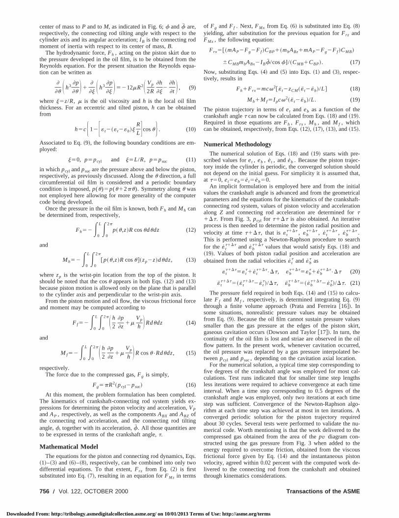
The first results to be presented focus on the forces actingthe piston as it moves up and down. Figures 7~a! and ~b! presentthe forces along the radial and axial directions, respectively, f
Fig. 7 Forces acting on the piston as a function of crankshaftangle: „a… radial; „b… axial
Table 1 Geometric, dynamic, and operational baseline param-eters used in the simulation
Journal of Tribology
rom: http://tribology.asmedigitalcollection.asme.org/ on 10/01/2013 Term
ro-putd in
on
r a
complete piston cycle. A minor role is played by the inertial forcFi(52meCM), as observed from the figures; along the raddirection the influence of inertia on the piston dynamics is virally none. Comparing Figs. 7~a! and ~b!, it is seen that along theaxial direction the forces are one order of magnitude higher tthose along the radial direction. For both directions the forreach their highest values close to the top dead center (t5180deg!. The connecting rod force,Fr , is balanced mainly by thehydrodynamic force along the radial direction and by the gas foalong the axial direction. From Fig. 7~b! it is also seen that thefriction force, F f , is negligible. A further comment should bmade with respect to the oscillation of bothFg and Frz close tothe top dead center. This behavior is related to the oscillationthe compressor discharge pressure as shown in Fig. 3, and isto valve fluttering.
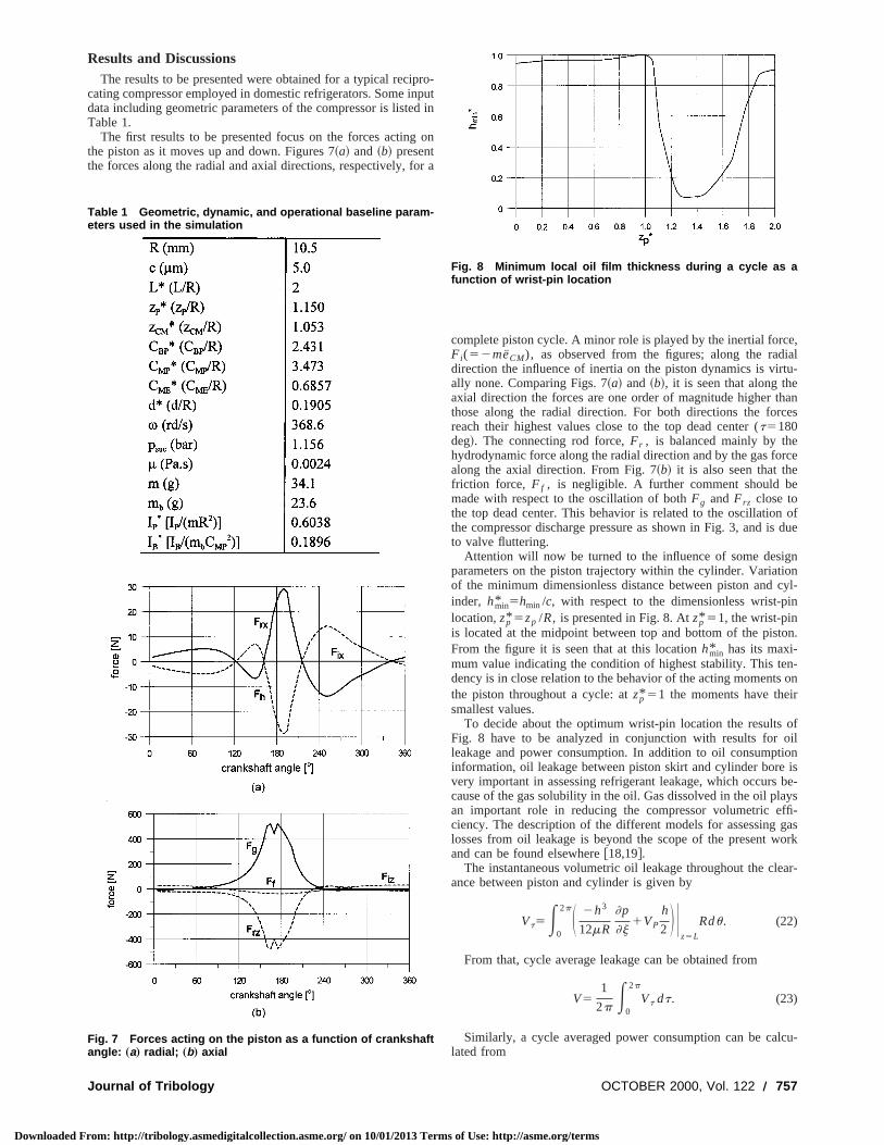
Attention will now be turned to the influence of some desiparameters on the piston trajectory within the cylinder. Variatof the minimum dimensionless distance between piston andinder, hmin* 5hmin /c, with respect to the dimensionless wrist-plocation,zp* 5zp /R, is presented in Fig. 8. Atzp* 51, the wrist-pinis located at the midpoint between top and bottom of the pistFrom the figure it is seen that at this locationhmin* has its maxi-mum value indicating the condition of highest stability. This tedency is in close relation to the behavior of the acting momentsthe piston throughout a cycle: atzp* 51 the moments have theismallest values.
To decide about the optimum wrist-pin location the resultsFig. 8 have to be analyzed in conjunction with results forleakage and power consumption. In addition to oil consumptinformation, oil leakage between piston skirt and cylinder borevery important in assessing refrigerant leakage, which occurscause of the gas solubility in the oil. Gas dissolved in the oil plaan important role in reducing the compressor volumetric eciency. The description of the different models for assessinglosses from oil leakage is beyond the scope of the present wand can be found elsewhere@18,19#.
The instantaneous volumetric oil leakage throughout the cleance between piston and cylinder is given by
Vt5E0
2pS 2h3
12mR
]p
]j1VP
h
2 D Uz5L
Rdu. (22)
From that, cycle average leakage can be obtained from
V51
2p E0
2p
Vt dt. (23)
Similarly, a cycle averaged power consumption can be calated from
Fig. 8 Minimum local oil film thickness during a cycle as afunction of wrist-pin location
OCTOBER 2000, Vol. 122 Õ 757
s of Use: http://asme.org/terms
h
s
ra
s
td
a
1
s thet al.
n
celuesvis-be
h is-
rt,
ss
ryigherlso
Downloaded F
P51
2p E0
2p
Pt dt, Pt5F fVP , (24)
wherePt is the instantaneous power consumption obtained frthe friction forceF f , Eq. ~14!, and piston velocityVP .
Integration of Eqs.~14! and ~22! were performed numericallyvisiting all control volumes of the computational mesh. Becauof cavitation, control volumes located in regions void of lubricawere disregarded during the integration.
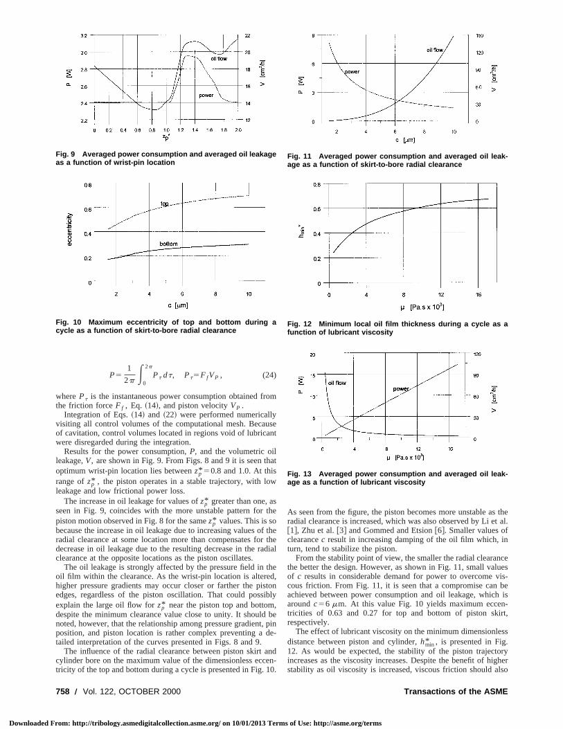
Results for the power consumption,P, and the volumetric oilleakage,V, are shown in Fig. 9. From Figs. 8 and 9 it is seen toptimum wrist-pin location lies betweenzp* 50.8 and 1.0. At thisrange ofzp* , the piston operates in a stable trajectory, with loleakage and low frictional power loss.
The increase in oil leakage for values ofzp* greater than one, aseen in Fig. 9, coincides with the more unstable pattern forpiston motion observed in Fig. 8 for the samezp* values. This is sobecause the increase in oil leakage due to increasing values oradial clearance at some location more than compensates fodecrease in oil leakage due to the resulting decrease in the rclearance at the opposite locations as the piston oscillates.
The oil leakage is strongly affected by the pressure field inoil film within the clearance. As the wrist-pin location is alterehigher pressure gradients may occur closer or farther the piedges, regardless of the piston oscillation. That could possexplain the large oil flow forzp* near the piston top and bottomdespite the minimum clearance value close to unity. It shouldnoted, however, that the relationship among pressure gradienposition, and piston location is rather complex preventing atailed interpretation of the curves presented in Figs. 8 and 9.
The influence of the radial clearance between piston skirtcylinder bore on the maximum value of the dimensionless ecctricity of the top and bottom during a cycle is presented in Fig.
Fig. 9 Averaged power consumption and averaged oil leakageas a function of wrist-pin location
Fig. 10 Maximum eccentricity of top and bottom during acycle as a function of skirt-to-bore radial clearance
758 Õ Vol. 122, OCTOBER 2000
rom: http://tribology.asmedigitalcollection.asme.org/ on 10/01/2013 Term
om
sent
at
w
the
f thethedial
thed,ton
ibly,be
, pine-
nden-0.
As seen from the figure, the piston becomes more unstable aradial clearance is increased, which was also observed by Li e@1#, Zhu et al.@3# and Gommed and Etsion@6#. Smaller values ofclearancec result in increasing damping of the oil film which, iturn, tend to stabilize the piston.
From the stability point of view, the smaller the radial clearanthe better the design. However, as shown in Fig. 11, small vaof c results in considerable demand for power to overcomecous friction. From Fig. 11, it is seen that a compromise canachieved between power consumption and oil leakage, whicaroundc56 mm. At this value Fig. 10 yields maximum eccentricities of 0.63 and 0.27 for top and bottom of piston skirespectively.
The effect of lubricant viscosity on the minimum dimensionledistance between piston and cylinder,hmin* , is presented in Fig.12. As would be expected, the stability of the piston trajectoincreases as the viscosity increases. Despite the benefit of hstability as oil viscosity is increased, viscous friction should a
Fig. 11 Averaged power consumption and averaged oil leak-age as a function of skirt-to-bore radial clearance
Fig. 12 Minimum local oil film thickness during a cycle as afunction of lubricant viscosity
Fig. 13 Averaged power consumption and averaged oil leak-age as a function of lubricant viscosity
Transactions of the ASME
s of Use: http://asme.org/terms
s
fl
oo
t
e
o
e
lt
a
o
et
r
g
n,
,
n
l
al’’
-n
ed
or-
al
,’’
as-
onri-
Downloaded F
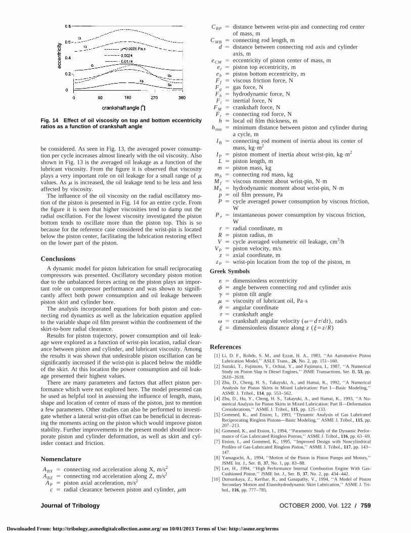
be considered. As seen in Fig. 13, the averaged power consution per cycle increases almost linearly with the oil viscosity. Alshown in Fig. 13 is the averaged oil leakage as a function oflubricant viscosity. From the figure it is observed that viscosplays a very important role on oil leakage for a small range omvalues. Asm is increased, the oil leakage tend to be less andaffected by viscosity.
The influence of the oil viscosity on the radial oscillatory mtion of the piston is presented in Fig. 14 for an entire cycle. Frthe figure it is seen that higher viscosities tend to damp outradial oscillation. For the lowest viscosity investigated the pisbottom tends to oscillate more than the piston top. This isbecause for the reference case considered the wrist-pin is locbelow the piston center, facilitating the lubrication restoring effon the lower part of the piston.
ConclusionsA dynamic model for piston lubrication for small reciprocatin
compressors was presented. Oscillatory secondary piston mdue to the unbalanced forces acting on the piston plays an imtant role on compressor performance and was shown to sigcantly affect both power consumption and oil leakage betwpiston skirt and cylinder bore.
The analysis incorporated equations for both piston and cnecting rod dynamics as well as the lubrication equation appto the variable shape oil film present within the confinement ofskirt-to-bore radial clearance.
Results for piston trajectory, power consumption and oil leage were explored as a function of wrist-pin location, radial cleance between piston and cylinder, and lubricant viscosity. Amthe results it was shown that undesirable piston oscillation cansignificantly increased if the wrist-pin is placed below the middof the skirt. At this location the power consumption and oil leaage presented their highest values.
There are many parameters and factors that affect pistonformance which were not explored here. The model presentedbe used as helpful tool in assessing the influence of length, mshape and location of center of mass of the piston, just to mena few parameters. Other studies can also be performed to invgate whether a lateral wrist-pin offset can be beneficial in decring the moments acting on the piston which would improve pisstability. Further improvements in the present model should incporate piston and cylinder deformation, as well as skirt and cinder contact and friction.
Nomenclature
ABX 5 connecting rod acceleration along X, m/s2
ABZ 5 connecting rod acceleration along Z, m/s2
AP 5 piston axial acceleration, m/s2
c 5 radial clearance between piston and cylinder,mm
Fig. 14 Effect of oil viscosity on top and bottom eccentricityratios as a function of crankshaft angle
Journal of Tribology
rom: http://tribology.asmedigitalcollection.asme.org/ on 10/01/2013 Term
mp-o
theity
ess
-mtheonsoatedct
gtion
por-nifi-en
on-iedhe
k-ar-ngbe
lek-
per-canass,tionesti-as-onor-yl-
CBP 5 distance between wrist-pin and connecting rod centeof mass, m
CMB 5 connecting rod length, md 5 distance between connecting rod axis and cylinder
axis, meCM 5 eccentricity of piston center of mass, m
et 5 piston top eccentricity, meb 5 piston bottom eccentricity, mF f 5 viscous friction force, NFg 5 gas force, NFh 5 hydrodynamic force, NFi 5 inertial force, N
FM 5 crankshaft force, NFr 5 connecting rod force, Nh 5 local oil film thickness, m
hmin 5 minimum distance between piston and cylinder durina cycle, m
I B 5 connecting rod moment of inertia about its center ofmass, kg•m2
I P 5 piston moment of inertia about wrist-pin, kg•m2
L 5 piston length, mm 5 piston mass, kg
mb 5 connecting rod mass, kgM f 5 viscous moment about wrist-pin, N•mMh 5 hydrodynamic moment about wrist-pin, N•m
p 5 oil film pressure, PaP 5 cycle averaged power consumption by viscous frictio
WPt 5 instantaneous power consumption by viscous friction
Wr 5 radial coordinate, mR 5 piston radius, mV 5 cycle averaged volumetric oil leakage, cm3/h
VP 5 piston velocity, m/sz 5 axial coordinate, m
zP 5 wrist-pin location from the top of the piston, m
Greek Symbols
« 5 dimensionless eccentricityf 5 angle between connecting rod and cylinder axisg 5 piston tilt anglem 5 viscosity of lubricant oil, Pa•su 5 angular coordinatet 5 crankshaft anglev 5 crankshaft angular velocity (v5dt/dt), rad/sj 5 dimensionless distance alongz (j5z/R)
References@1# Li, D. F., Rohde, S. M., and Ezzat, H. A., 1983, ‘‘An Automotive Pisto
Lubrication Model,’’ ASLE Trans.,26, No. 2, pp. 151–160.@2# Suzuki, T., Fujimoto, Y., Ochiai, Y., and Fujimura, I., 1987, ‘‘A Numerica
Study on Piston Slap in Diesel Engines,’’ JSME Transactions, Ser. B,53, pp.2610–2618.
@3# Zhu, D., Cheng, H. S., Takayuki, A., and Hamai, K., 1992, ‘‘A NumericAnalysis for Piston Skirts in Mixed Lubrication: Part I—Basic Modeling,ASME J. Tribol.,114, pp. 553–562.
@4# Zhu, D., Hu, Y., Cheng, H. S., Takayuki, A., and Hamai, K., 1993, ‘‘A Numerical Analysis for Piston Skirts in Mixed Lubrication: Part II—DeformatioConsiderations,’’ ASME J. Tribol.,115, pp. 125–133.
@5# Gommed, K., and Etsion, I., 1993, ‘‘Dynamic Analysis of Gas LubricatReciprocating Ringless Pistons—Basic Modeling,’’ ASME J. Tribol.,115, pp.207–213.
@6# Gommed, K., and Etsion, I., 1994, ‘‘Parametric Study of the Dynamic Perfmance of Gas Lubricated Ringless Pistons,’’ ASME J. Tribol.,116, pp. 63–69.
@7# Etsion, I., and Gommed, K., 1995, ‘‘Improved Design with NoncylindricProfiles of Gas-Lubricated Ringless Piston,’’ ASME J. Tribol.,117, pp. 143–147.
@8# Yamaguchi, A., 1994, ‘‘Motion of the Piston in Piston Pumps and MotorsJSME Int. J., Ser. B,37, No. 1, pp. 83–88.
@9# Lee, H., 1994, ‘‘High Performance Internal Combustion Engine With GCushioned Piston,’’ JSME Int. J., Ser. B,37, No. 2, pp. 434–442.
@10# Dursunkaya, Z., Keribar, R., and Ganapathy, V., 1994, ‘‘A Model of PistSecondary Motion and Elastohydrodynamic Skirt Lubrication,’’ ASME J. Tbol., 116, pp. 777–785.
OCTOBER 2000, Vol. 122 Õ 759
s of Use: http://asme.org/terms
eh
e
om-
ing
v.
them-
ofon-
Downloaded F
@11# Fang, Y., and Shirakashi, M., 1995, ‘‘Mixed Lubrication Characteristics Btween the Piston and Cylinder in Hydraulic Piston Pump-Motor,’’ ASMETribol., 117, pp. 80–85.
@12# Liu, K., Xie, Y. B., and Gui, C. L., 1998, ‘‘A Comprehensive Study of thFriction and Dynamic Motion of the Piston Assembly,’’ Proc. Inst. MecEng.,212, Part J, pp. 221–226.
@13# Fagotti, F., Todescat, M. L., Ferreira, R. T. S., and Prata, A. T., 1994, ‘‘HTransfer Modeling in a Reciprocating Compressor,’’Proceedings of the Inter-national Compressor Engineering Conference at Purdue, West Lafayette, IN,pp. 605–610.
@14# Todescat, M. L., Fagotti, F., Prata, A. T., and Ferreira, R. T. S., 1992, ‘‘Thmal Energy Analysis in Reciprocating Hermetic Compressors,’’Proceedingsof the International Compressor Engineering Conference at Purdue, Vol. IV,West Lafayette, IN, pp. 1419–1428.
@15# Catto, A. G., and Prata, A. T., 1997, ‘‘A Numerical Study of Instantaneo
760 Õ Vol. 122, OCTOBER 2000
rom: http://tribology.asmedigitalcollection.asme.org/ on 10/01/2013 Term
e-J.
.
at
er-
us
Heat Transfer During Compression and Expansion in Piston-Cylinder Geetry,’’ Proceedings of the ASME Advanced Energy System Division, AES-Vol.37, pp. 441–450.
@16# Prata, A. T., and Ferreira, R. T. S., 1990, ‘‘The Accuracy of Short BearTheory in Presence of Cavitation,’’ ASME J. Tribol.,112, pp. 650–654.
@17# Dowson, D., and Taylor, C. M., 1979, ‘‘Cavitation in Bearings,’’ Annu. ReFluid Mech.,11, pp. 35–66.
@18# Gasche, J. L., Ferreira, R. T. S., and Prata, A. T., 1999, ‘‘Transient Flow ofOil-Refrigerant Mixture Through the Radial Clearance in Rolling Piston Copressor,’’Proceedings of the ASME Advanced Energy System Division, AES-Vol. 39, pp. 119–127.
@19# Gasche, J. L., Ferreira, R. T. S., and Prata, A. T., 2000, ‘‘Two-Phase Flowthe Oil-Refrigerant Mixture Through the Radial Clearance in Rolling PistCompressor,’’ accepted to theInternational Compressor Engineering Conference at Purdue, West Lafayette, IN.
Transactions of the ASME
s of Use: http://asme.org/terms