dynamic behavior of elastically tailored rotating blades...
TRANSCRIPT

International Journal of Rotating Machinery, 8(1): 13±25, 2002
Copyright # 2002 Taylor & Francis
1023-621X/02 $12.00� .00
Dynamic Behavior of Elastically Tailored RotatingBlades Modeled as Pretwisted Thin-Walled Beamsand Incorporating Adaptive Capabilities
OHSEOP SONG1, SANG-YONG OH1, and LIVIU LIBRESCU2,*1Chungnam National University, Taejon, South Korea;2Virginia Polytechnic Institute and State University, Blacksburg, Virginia 24061, USA
A number of issues related with the vibrational behavior of
rotating blades modeled as pretwisted thin-walled anisotropic
beams, incorporating adaptive capabilities are addressed.
The adaptive capabilities are provided by a system of
piezoactuators bonded or embedded into the structure. Based
on the converse piezoelectric e�ect and on the out-of-phase
activation, boundary control moments are piezoelectrically
induced at the beam tip. A feedback control law relating the
induced bending moments with the kinematical response
quantities appropriately selected is used, and its bene®cial
e�ects, considered in conjunction with that of the beam
anisotropy and structural pretwist upon the closed/open loop
eigenvibration characteristics are highlighted.
Keywords: Rotating blades; Thin-walled beams; Adaptive materials;Feedback control; Flapping-lagging motion; Structural tailoring
In the continuous quest for improved e�ciency and higher
performance of rotorcraft structures and turbomachines
operating in severe environmental conditions, there is a
stringent need for new paradigms able to enhance the
vibrational behavior of these structures.
Enhancement of the dynamic response of these devices
would result in higher e�ciency and higher thrust-to-
weight ratio, lower vibrational levels, lighter rotorcraft
structures, with less susceptibility to fatigue failure. More-
over, implementation of the new methods in the turbo-
machinery for space applications, would result in a
considerable increase of their fatigue life.
The design of advanced rotor blades was signi®cantly
in¯uenced by the incorporation of composite materials
technology. As compared to their metallic counterparts,
composite design of rotor blades o�ers considerable
advantages with respect to strength and weight criteria,
in addition to providing adequate means of e�ciently
controlling their static and dynamic response via im-
plementation of structural tailoring.
However, in order to enhance their dynamic behavior
and avoid vibration-induced fatigue failure, in addition to
the tailoring technique which is passive in nature, new
technologies have to be implemented. One of the ways to
accomplish such goals consists of the incorporation into
the host structure of adaptive materials technology. In this
case the structures are referred to as intelligent or smart
structures. In constrast to traditional passive structures, in
those featuring adaptive capabilities, the natural frequen-
cies, damping and mode shapes can be tuned to avoid
structural reasonance and enhance dynamic response
characteristics. In addition, due to the nature of intelligent
structures which feature a highly distributed network of
sensors and actuators, more encompassing feedback
control schemes would be feasible to the implemented.
For helicopter and tilt rotor aircraft, the incorporation
of adaptive materials technology for vibration control
could result in signi®cant increases, among others, in com-
fort, range, fatigue life. In this sense, piezoelectric materials
are excellent candidates for the role of sensors and
actuators.
Within this study, an investigation of the free vibration
of pretwisted rotating blades modeled as thin-walled beams
whose material is characterized by anisotropic properties,
and incorporating the adaptive capability, referred to as
strain actuation, will be carried out.
The adaptive capability is achieved through the converse
peizoelectric e�ect consisting of the generation of localized
strains in response to an applied voltage. The induced
strain ®eld produces, in turn, an adaptive change in the
dynamic response characteristics of the structure.
Received 14 December 1999; In ®nal form 7 April 2000.*Corresponding author. Tel.: 540 231-4574, Fax: 540 231-4574, e-mail:
13

Implementation of a feedback control law relating the
applied electric ®eld to one of the mechanical quantities
characterizing the blade response according to a prescribed
functional relationship, results in a closed-loop eigenvalue
problem. Its solution supplies the closed-loop eigenvalues
which are functions of the applied voltage, i.e., of the
feedback control gain.
Under consideration is a blade rotating with constant
angular velocity and modelled as a pretwisted, single-cell
thin/thick walled beam.
Although of an evident practical importance, to the best
of the authors' knowledge no studies related to the topic of
this investigation can be found in the specialized literature.
Even for the non-adaptive case, the literature devoted to the
free vibration problem of rotating composite blades modeled
as pretwisted thin-walled beams reveals an extreme paucity
of results. The survey-paper, by Rosen (1991), presenting
the state of the art in the area of pretwisted rotating blades,
and the papers by Sunar and Rao (1999) and Crawley
(1994), summarizing the achievements reached in the area
of intelligent structures, in general and its prospects of
its incorporation in aerospace constructions, respectively,
con®rm in full this statement. The goal of this paper is to
®ll the existing gap and supply pertinent information in this
area. The results reported herein constitute a generalization
and continuation of those previously obtained by Song
and Librescu (1993, 1997a, b, c, 1999) and Librescu et al.
(1996).
BASIC ASSUMPTIONS
In the following section, a short account of the basic
equations to be used will be presented. Herein, the case of a
straight pretwisted ¯exible beam of length L rotating with
the constant angular velocity V normal to the plane of
rotation is considered. The origin of the rotating axis system
(x, y, z) is located at the blade root at an o�set R0 from the
rotation axis ®xed in space. R0 denotes also the radius of the
hub (considered to be rigid), at which the blade is mounted
and which rotates about its polar axis through the origin 0
(see Fig. 1).
Besides the coordinates (x, y, z), the local coordinates
(x p, y p, z p) are also de®ned where xp and y p are the
principal axes of an arbitrary beam cross-section Song and
Librescu (1997a).
The two coordinate systems are related by the following
transformation formulae:
x�s; z� � xp�s�cos� ÿ yp�s�sin �
y�s; z� � xp�s�sin � � yp�s�cos�
z�s� � zp
�1aÿ c�
where �(z)� �0z, denotes the pretwist of the current
section, whereas �0 denotes the pretwist per unit beam
length.
The inertial reference system (X,Y,Z) is attached to the
center of the hub O. By (i, j, k) and (I, J, K ) we de®ne the
unit vectors associated with the frame coordinates (x, y, z)
and (X,Y,Z ), respectively. In addition, a local (surface)
coordinate system (s, z, n) associated with the beam is
considered. Its geometric con®guration and the typical
cross-section along with the associated system of coordi-
nates are presented in Figure 1.
Within the present work, the precone and pre-setting
of the blade are assumed to be zero. It is further assumed
that the rotation takes place in the plane (X,Z) with the
constant angular velocity V(�J�j), the spin axis
being along the Y-axis.
Concerning the beam spanwise z-coordinate axis, it
coincides with a straight unspeci®ed reference axis.
Toward its modeling, the following assumptions are
adopted: (i) the original cross-section of the beam is
preserved, (ii) transverse shear, rotatory inertia and centri-
fugal accelerations are included, and ®nally, (iii) a special
lay-up inducing ¯apwise-chordwise bending coupling is
implemented.
KINEMATICS
In light of the previously mentioned assumptions, and in
order to reduce the 3-D elasticity problem to an equivalent
FIGURE 1 Geometry of the pretwisted beam and its cross-section withthe embedded piezoactuators.
14 O. SONG ET AL.

1-D one, the components of the displacement vector are
represented as (see e.g., Librescu et al., 1996, 1997 and
Song and Librescu, 1997c).
u�x; y; z; t� � u0�z; t� ÿ y��z; t�eeeeeeee;v�x; y; z; t� � v0�z; t� � x��z; t�eeeeeeee;w�x; y; z; t� � w0�z; t� � �x�z; t�
�y�s� ÿ n
dx
ds
�
� �y�z; t�
�x�s� � n
dy
ds
�ÿ �0 �z; t��F!�s� � na�s��eeeeeeeeeeeeeeeeeeeeeeee :
�2aÿ c�
In these equations u0(z; t), v0(z; t), w0(z; t) denote the rigid
body translations along the x, y and z axes while �(z; t) and�x(z; t), �y(z, t) denote the elastic twist about the z-axis andthe rotations about the x and y-axes, respectively. The
expressions of �x and �y are
�x�z; t� � yz�z; t� ÿ v 00�z; t�;
�y�z; t� � xz�z; t� ÿ u 00�z; t�;�3a; b�
In Eqs. [2], F!(s) and na(s) play the role of primary and
secondary warping functions, respectively. For their
de®nition see e.g., Song and Librescu (1993). However,
having in view that our analysis will concern the case
of rotating thin-walled beams featuring the bending ±
bending elastic coupling, the quantities associated with the
twist � and axial displacement w0 become immaterial. The
terms associated with the twist e�ect are underscored in
Eqs. [2] by an undulated line.
In the absence of transverse shear e�ects, from Eqs.
[3a, b] is readily seen that
�x�z; t� � ÿv 00�z; t�; �y�z; t� � ÿu 00�z; t�: �4a; b�
In these equations, as well as in the forthcoming ones,
the primes denote di�erentiation with respect to the
longitudinal z-coordinate. The position vector of a point
M(x, y, z) belonging to the deformed structure is
R�x; y; z; t� � �x� u�i� �y� v�j
� �z� w�k� R0
�5�
where x, y and z are the Cartesian coordinates of the points
of the continuum in its undeformed state, while u, v and w
denote displacement components de®ned through Eqs. [2].
Recalling that the spin rate was assumed to be constant,
with the help of equations expressing the time derivatives
of unit vectors (i, j, k), one obtain the velocity and ac-
celeration vectors of an arbitrary point M of the beams
under the form
_R � Vxi� Vyj� Vzk �6a�
and
�R � axi� ayj� azk �6b�
respectively, where their components are as follows:
Vx � _u� �R0 � z� w�; Vy � _v;
Vz � _wÿ �x� u��7aÿ c�
and
ax � �u� 2 _wÿ �x� u�2; ay � �v;
az � �wÿ 2 _uÿ �R0 � z� w�2�8aÿ c�
In these equations and the following ones, the superposed
dots denote time derivatives, whereas the terms under-
scored by one or two superposed solid lines are associated
with Coriolis and centrifugal inertia terms, respectively.
EQUATIONS OF MOTION
AND BOUNDARY CONDITIONS
The equations of motion of rotating pretwisted beams
and the associated boundary conditions, can be obtained
via the application of Hamilton's variational principle.
In various contexts related with the dynamic modeling
of thin-walled beam, this principle was thoroughly used
(see e.g., Song and Librescu, 1993, 1997a, b, c, 1999 and
Librescu et al., 1996, 1997) and for this reason, herein, only
the basic steps enabling one to get the ®nal governing
equations will be outlined.
The governing system of elastic rotating blades will
be expressed, as is customary, in terms of displacement
quantitites. This can be accomplished by replacing in the
equations of motion and static boundary conditions the
1-D stress-resultants and stress-couples represented in
terms of displacement quantities. All these steps are not
carried out here.
For the general case of anisotropy of constituent
materials and ply-stacking sequence, the obtained govern-
ing system and the associated boundary conditions would
exhibit a complete coupling between the various modes,
i.e., warping (primary and secondary), bending (¯apping
and lagging), twist, extension and transverse shearing. The
assessment of the in¯uence of these couplings and their
proper exploitation (see e.g., Librescu et al., 1996, 1997 and
Song and Librescu, 1997c) should constitute an important
task towards a rational design of blade structures of
15TAILORED ROTATING BLADES

helicopter and tilt rotor aircraft and of the proper use of
the exotic material characteristics (i.e., anisotropy and ply-
stacking sequence) generating these couplings.
Moreover, due to inclusion of the pretwist, additional
couplings are induced, which in such a general context,
would add additional complexities to the problem (see e.g.,
Kosmatka, 1992). For these reasons, in the present analysis
a special ply-angle distribution inducing the elastic coupling
between ¯apwise bending and chordwise bending, (referred
also to as ¯ap-lag or bending ± bending cross coupling),
will be considered. On the other hand, having in view that
Coriolis e�ect induces a coupling with the extensional
motion and since its contribution is considered to be neg-
ligeable, (see e.g., Ewins and Henry, 1992), this e�ect will be
discarded. This ply-angle distribution referred to as circum-
ferentially uniform sti�ness (CUS) con®guration is achieved
by skewing angle plies with respect to the beam axis
according to the law �( y)� �(ÿ y) in the top and bottom
¯anges, and to the law �(x)� �(ÿx) in the lateral webs.
Angle � denotes the dominant ply orientation measured
from the positive s-axis towards the positive z-axis. Consis-
tent with this ply-angle con®guration, the following govern-
ing equations incorporating transverse shear e�ects and
coupling the ¯apwise and chordwise bendings are obtained:
�u0 : �a43�z��0x � a44�z��u
00 � �y�
� a45�z��v00 � �x��
0
ÿ b1�u0 � b1u02 � b1
2�R�z�u 00�0 � 0;
�v0 : �a52�z��0y � a55�z��v
00 � �x�
� a45�z��u00 � �y��
0
ÿ b1�v0 � b12�R�z�v 00�
0 � 0;
��y : �a22�z��0y � a25�z��v
00 � �x� � a23�z��
0x�0
ÿ a44�z��u00 � �y� ÿ a43�z��
0x
ÿ a45�z��v00 � �x�
ÿ �b5�z� � b15�z�����y ÿ 2�y�
ÿ �b6�z� ÿ b13�z����x � 0;
��x : �a33�z��0x � a23�z��
0y � a34�z��u
00 � �y��
0
ÿ a55�z��v00 � �x� ÿ a52�z��
0y
ÿ a54�z��u00 � �y�
ÿ �b4�z� � b14�z�����x ÿ 2�x�
ÿ �b6�z� ÿ b13�z�����y ÿ 2�y� � 0:
�9aÿ d�
In addition, assuming the blade to be clamped at z� 0 and
free at z�L, the boundary conditions result as:
At z� 0
u0 � 0; v0 � 0; �x � 0; �y � 0 �10aÿ d�
and at z�L:
�u0 : a43�z��0x � a44�z��u
00 � �y�
� a45�z��v00 � �x� � 0;
�v0 : a52�z��0y � a55�z��v
00 � �x�
� a45�z��u00 � �y� � 0;
��y : a22�z��0y � a25�z��v
00 � �x�
� a23�z��0x � My;
��x : a33�z��0x � a34�z��u
00 � �y�
� a23�z��0y � Mx:
�11a ÿ d�
In these equations (see Song and Librescu, 1997a)
R�z� �
�R0�Lÿ z� �
1
2�L2 ÿ z2�
�; �12�
whereas the coe�cients aij (z)� aji (z) and bi (z) denote
sti�ness and reduced mass terms, respectively.
The expressions of sti�ness quantities in terms of their
cross-section principal axes (xp, y p) counterparts are
recorded in the Appendix, together with those of the mass
terms. Equations [9] and [11] reveal that in the context of
above considered ply-angle con®guration, the ¯apwise and
chordwise bending are coupled with transverse shear. For
this case, the coupling sti�nesses a34 and a25 are a re¯ect
of this ply angle con®guration. In addition, the sti�ness
quantities a45 and a23 and the mass terms b6 and b13 which
are di�erent from zero only in the case of a pretwisted
beam, induce a supplementary coupling between the
¯apwise and chordwise motions. However, from the ex-
pressions of a45, a23, b6 and b13 (see the Appendix), it can
readily be seen that for an axisymmetric box-beam of a
square cross-section, these quantities vanish for any value
of �. As a result, in such a case, the ¯apwise-chordwise
coupling arises independently from the pretwist e�ect. It
should also be remarked that in addition to the above
mentioned coupling terms generated by pretwist, the
remaining ones involve, as a result of it, a more complex
feature. Their expressions displayed in Appendix sub-
stantiates in full this statement.
Notice that in addition to the above mentioned elastic
couplings induced by the above ply-angle distribution and
the pretwist, Eqs. [9] through [11] feature also the coupling
between the ¯apwise shear and chordwise bending and
between chordwise shear and ¯apwise bending. More-
over, the above governing equation system includes also
the centrifugal and rotatory inertia e�ects.
The system of Eqs. [9] through [11] corresponds to the
shearable beam model, whereas its classical counterpart
obtained when transverse shear e�ects are discarded, is
referred to as the nonshearable model. Within the theory of
16 O. SONG ET AL.

solid beams, this model is referred to as Bernoulli±Euler±
Rayleigh model. It should be mentioned that in the ex-
pressions of transverse shear stress resultants intervening
in the equations of motion, a transverse shear correction
factor k2� 5/6 was used.
NONSHEARABLE BEAM MODEL
COUNTERPART
Elimination of a44�u00 � �y� � a45�u0
0 � �x� and of a55�v00 �
�x� � a54�u00 � �y� in the groups of Eqs. [9a, c] and [9b, d],
respectively, followed by consideration of �x ! ÿv 00 and
�y � ÿu 00, yields the Bernoulli±Euler±Rayleigh counterpart
of Eqs. [9] through [11]. As a result, the governing
equations result as:
�u0 : �a22�z�u000 � a23�z�v
000�00
ÿ ��b5�z� � b15�z����u00ÿ2u 00�
ÿ �b6�z� ÿ b13�z���v00�0
� b1�u0ÿb12u0 ÿ b1
2�R�z�u 00�0 � 0;
�v0 : �a33�z�v000 � a23�z�u
000 �00
ÿ ��b4�z� � b14�z����v00ÿ2v 00�
� �b6�z� ÿ b13�z����u00 ÿ 2u00��
0
ÿ b1�v0 ÿ b12�R�z�v 00�
0 � 0:
�13a; b�
The associated boundary conditions are:
At z� 0
u0 � v0 � u 00 � v 00 � 0 �14aÿ d�
and at z�L:
�u0 : �a22�z�u000 � a23�z�v
000 �0
ÿ ��b5�z� � b15�z����u00 ÿ2u 00�
ÿ �b6�z� ÿ b13�z���v00� � 0;
�v0 : �a33�z�v000 � a23�z�u
000 �0
ÿ ��b4�z� � b14�z����v00 ÿ 2v 00�
� �b6�z� ÿ b13�z����u00 ÿ 2u 00�� � 0;
�u 00 : a22�z�u000 � a23�z�v
000 � My;
�v 00 : a33�z�v000 � a32�z�u
000 � Mx:
�15aÿ d�
In this case, the only ¯apping±lagging coupling sti�ness
induced by the pretwist e�ect is a23(z), whereas,
(b6(z)ÿb13(z)) represents the dynamic ¯apping±lagging
coupling term induced by pretwist.
Consistent with the number of four boundary conditions
at each edge, the governing equations for both shearable
and unshearable pretwisted rotating beams are of the eight
order. A noticeable di�erence between the shearable and
unshearable beam models consists of the fact that in the
former instance, in the boundary conditions at the tip the
eigenfrequencies do not intervene, whereas in the latter
one, these occur.
In Eqs. [11c, d] and their non-shearable counterparts,
Eqs. [15b, d], My and Mx stand for the piezoelectrically
induced bending moments about the axes y and x,
respectively, that appear as non-homogeneous terms in
the boundary conditions at z�L. It should be noticed that
Mx and My are di�erent from zero, only if external voltages
of opposite signs are applied on the top and bottom, and in
the lateral piezoactuator layers, respectively (out-of-phase
activation).
It should be remarked that in the light of the actuator
con®guration, the piezoelectrically induced stress-resultant
and stress-couples are independent upon the z-coordinate.
As a result, in the governing equations their contribution is
immaterial while in the boundary conditions they intervene
as non-homogeneous terms, only. This feature renders the
control to be accomplished via the piezoelectrically induced
boundary bending moments. At this point it should be
noticed that the feedback boundary control constitutes a
powerful way to control the static and dynamic response
of structures (see Librescu et al., 1996, 1997, 1999 and
Librescu and Na, 1998).
PIEZOACTUATORS AND CONTROL LAW
It is assumed that the master structure is composed of r
layers while the actuator is composed of p piezoelectric
layers. We stipulate that the actuators are distributed over
the entire span of the blade, whereas along the circumfer-
ential and transverse directions, i.e., along the s- and
n-directions are distributed according to the law
P�k��n� � H�nÿ n�kÿ�� ÿ H�nÿ n�k���;
P�k��s� � H�sÿ s�kÿ�� ÿ H�sÿ s�k���:�16�
Herein H denotes Heaviside's distribution, P is a spatial
function which de®nes the distribution of actuators in the
n and the s directions, and the subscript k identi®es the
a�liation of the respective quantity to the kth layer.
Assuming that the electric ®eld vector Ei is representedby its component E3 in the n-direction, coinciding with
the direction of polarization (referred to as thickness
17TAILORED ROTATING BLADES

polarization), the boundary moment controls are expressed
as
Mx �
I Xpk�1
E�k�3
ÿn�k�� ÿ n�kÿ�
�e�k�31 P�k��s�
�y
�1ÿ
A12
A11
��dx
ds
B12
A11
�ds
ÿ1
2
I �dx
ds
Xpk�1
E�k�3
ÿn2�k�� ÿ n2�kÿ�
�
e�k�31 P�k��s�
�ds;
My �
I Xpk�1
E�k�3
ÿn�k�� ÿ n�kÿ�
�e�k�31 P�k��s�
�x
�1ÿ
A12
A11
��dy
ds
B12
A11
�ds
�1
2
I �dy
ds
Xpk�1
E�k�3
ÿn2�k�� ÿ n2�kÿ�
�
e�k�31 P�k��s�
�ds:
�17a; b�
Herein e31 is the piezoelectric constant; Aij and Bij are
the standard local-sti�ness quantities associated with the
piezoactuators, whileH���ds denotes the integral around
the circumference of the mid-line cross-section of the beam.
For E3 constant throughout the piezoactuator thickness,this implying E
�k�3 � E3, Eqs. [17] can be expressed in
condensed form as:
Mx � E3Mx; My � E3My �18a; b�
where the meaning of Mx and My becomes evident by
comparing Eqs. [18] with [17].
Equations [17] reveal that the piezoelectrically induced
bending moments are proportional to the applied electric
®eld E3. Now, assuming that the piezoelectric elements can
be employed concurrently for sensing and actuation, for
sensing operation the electric displacement results as
D3 � e31Szz; �19�
and the sensor output voltage is expressed in the form (see
Dosch et al., 1992)
Vs�t� �qs�t�
Cp
; �20�
where the electric charge qs(t) is
qs�t� �
ZAs
D3dAs �
ZAs
e31SzzdAs; �21�
Cp and As denoting the sensor's capacitance and piezo-
electric patch area, respectively, while Szz denotes the axial
strain component (see Song and Librescu, 1993 and
Librescu et al., 1997). Assuming the sensor patches being
located symmetrically on the opposite walls, i.e., on
y� � b/2 and x� � c/2, having in view the expression
of Szz and Eqs. [19] through [21], Vxs �t� and Vy
s �t� are
expressible as:
Vxs �t� � Cs
x�x�L; t�; V ys�t� � Cs
y�y�L; t� �22a; b�
where the expressions of Csy and Cs
x are not displayed here.
The feedback control law to be used here is referred to as
the proportional feedback control law.
Within this control law, one postulates that the actuating
electric ®eld is proportional to the sensor output voltage,
which implies
Ex3�t� � KpVxs �t�=ha; Ey3�t� � KpV
ys �t�=ha �23a; b�
where ha is the thickness of the piezopatch.
Consequently, replacement of Eqs. [23] considered in
conjunction with Eqs. [22] into Eqs. [18] results in the
piezoelectrically induced bending moments expressed as:
My�L; t� �KpCMa
y
ha�Cs
y�y�L; t�� � KpC11�y�L; t�; �24a�
Mx�L; t� �KpCMa
x
ha�Cs
x�x�L; t�� � KpC22�x�L; t�: �24b�
The results yielding the piezoelectrically induced bending
moments, Eqs. [24], reveal that these are obtained through
the combination of both sensing and actuation functions.
Herein
CMay�Xrk�1
e�k�31
��1ÿ
A11
A11
�ÿn�k�� ÿ n�kÿ�
�c
�ÿn2�k�� ÿ n2�kÿ�
�ÿ 2
B12
A11
ÿn�k�� ÿ n�kÿ�
��p2; �25a�
CMax�Xrk�1
e�k�31
��1ÿ
A11
A12
�ÿn�k�� ÿ n�kÿ�
�b
�ÿn2�k�� ÿ n2�kÿ�
�ÿ 2
B12
A11
ÿn�k�� ÿ n�kÿ�
��p1 �25b�
where p1 and p2 denote the lengths of the piezoactuators
along the x- and y-directions (see Figure 1b), while r stands
for the number of piezoactuator layers.
18 O. SONG ET AL.
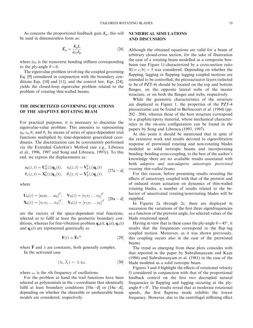
As concerns the proportional feedback gain Kp, this will
be used in dimensionless form as:
Kp �KpL
a33hp�26�
where a33 is the transverse bending sti�ness corresponding
to the ply-angle �� 0.
The eigenvalue problem involving the coupled governing
Eq. [9] considered in conjunction with the boundary con-
ditions Eqs. [10] and [11], and the control law, Eqs. [24],
yields the closed-loop eigenvalue problem related to the
problem of rotating thin-walled beams.
THE DISCRETIZED GOVERNING EQUATIONS
OF THE ADAPTIVE ROTATING BEAM
For practical purposes, it is necessary to discretize the
eigenvalue-value problem. This amounts to representing
u0, v0, �x and �y by means of series of space-dependent trialfunctions multiplied by time-dependent generalized coor-
dinates. The discretization can be conveniently performed
via the Extended Galerkin's Method (see e.g., Librescu
et al., 1996, 1997 and Song and Librescu, 1997c). To this
end, we express the displacements as:
u0�z; t� � UT0 �z�qu�t�; v0�z; t� � VT
0 �z�qv�t�
�x�z; t� � XT0 �z�qx�t�; �y�z; t� � YT
0 �z�qy�t�:�27aÿ d�
where
U0�z� � �u1u2 . . . uN �T ; V0�z� � �v1v2 . . . vN �
T
X0�z� � �x1x2 . . . xN �T ; Y0�z� � �y1y2 . . . yN �
T�28aÿ d�
are the vectors of the space-dependent trial functions,
selected as to ful®l at least the geometric boundary con-
ditions, whereas for free-vibration problem qu(t), qv(t), qx(t)
and qy(t) are represented generically as
F�t� � Fe�t �29�
where F and � are constants, both generally complex.
In the activated case
��r; �r� � � i!r �30�
where !r is the rth frequency of oscillations.
For the problem at hand the trail functions have been
selected as polynomials in the z-coordinate that identically
ful®l at least boundary conditions [10a ± d] or [14a ± d],
depending on whether the shearable or unshearable beam
models are considered, respectively.
NUMERICAL SIMULATIONS
AND DISCUSSION
Although the obtained equations are valid for a beam of
arbitrary closed-cross section, for the sake of illustration
the case of a rotating beam modelled as a composite box-
beam (see Figure 1) characterized by a cross-section ratio
R�� c=b� � 5 was considered. Depending on whether the
¯apping, lagging or ¯apping±lagging coupled motions are
intended to be controlled, the piezoactuator layers (selected
to be of PZT-4) should be located on the top and bottom
¯anges, on the opposite lateral webs of the master
structure, or on both the ¯anges and webs, respectively.
While the geometric characteristics of the structure
are displayed in Figure 1, the properties of the PZT-4
piezoceramic can be found in Berlincourt et al. (1964) (pp.
202 ± 204), whereas those of the host structure correspond
to a graphite/epoxy material, whose mechanical character-
istics in the on-axis con®guration can be found in the
papers by Song and Librescu (1993, 1997).
At this point it should be mentioned that in spite of
the extensive work and results devoted to eigenvibration
response of pretwisted rotating and non-rotating blades
modeled as solid isotropic beams and incorporating
bending±bending cross-coupling, to the best of the author's
knowledge there are no available results associated with
both adaptive and non-adaptive anisotropic pretwisted
rotating thin-walled beams.
For this reason, before presenting results revealing the
e�ects of anisotropy coupled with that of the pretwist and
of induced strain actuation on dynamics of thin-walled
rotating blades, a number of results related to the be-
havior of unactivated rotating/nonrotating blades will be
supplied.
In Figures 2a through 2c, there are displayed in
succession the variations of the ®rst three eigenfrequencies
as a function of the pretwist angle, for selected values of the
blade rotational speed.
Having in view that in these cases the ply-angle �� 45�, it
results that the frequencies correspond to the ¯ap±lag
coupled motion. Moreover, as it was shown previously,
this coupling occurs also in the case of the pretwisted
beams.
The trend as emerging from these plots coincides with
that reported in the paper by Subrahmanyam and Kaza
(1986) and Subrahmanyam et al. (1981) in the case of the
blade modeled as a solid isotropic beam.
Figures 3 and 4 highlight the e�ects of rotational velocity
considered in conjunction with that of the proportional
feedback control on the ®rst two decoupled natural
frequencies in ¯apping and lagging occuring at the ply-
angle �� 0�. The results reveal that at moderate rotational
speeds, the ®rst ¯apwise mode exhibits the lowest
frequency. However, due to the centrifugal sti�ening e�ect
19TAILORED ROTATING BLADES

(which is much more signi®cant in the ¯apping modes),
beyond a certain angular speed the lagging frequency
becomes the lower of the two. Figure 3 reveals that for the
unactivated beam (case corresponding to Kp � 0), in the
vicinity of ~� 150 rad=sec, a frequency crossing of laggingand ¯apping modes occurs.
The results also reveal that for the activated beams (i.e.,
for Kp 6� 0), the frequency crossing is shifted towards larger
rotational velocities. At the same time, the supplied results
show that the piezoelectric actuation has a more powerful
e�ect on the lagging eigenfrequencies than on the ¯apping
ones. This trend remains still valid for higher mode
frequencies.
Moreover, as Figure 4 reveals, for the second mode
frequency, the ¯apping±lagging frequency crossing occurs
at much larger values of as compared to that occuring
for the fundamental frequencies. It should also be observed
that for second mode frequency, the piezoelectric actuation
becomes e�cient for the ¯apping frequencies as well.
Associated with the ply-angle �� 90� the variation of the
®rst mode frequency with as displayed in Figure 5,
reveals a similar trend to that supplied in Figure 3 for
�� 0�. In this case, however, due to the larger bending
sti�nesses a33 and a22 in ¯apping and lagging as induced by
this ply-angle, (see Librescu et al., 1996), the frequencies
are much higher within the entire range of rotational
speeds than their counterparts corresponding to �� 0�. In
addition, the frequency crossings for both the unactivated
and the activated rotor blade take place at much larger
rotational speeds. In the case of higher mode numbers,
FIGURE 2a Variation of ®rst coupled ¯apping ± lagging naturalfrequency vs. pretwist angle for selected rotational speeds (�� 45�).
FIGURE 2b Counterpart of Figure 2a for the second coupled modefrequency.
FIGURE 2c Counterpart of Figure 2a for the third coupled modefrequency.
FIGURE 3 Variation of ®rst decoupled ¯apping and lagging naturalfrequencies vs. rotational speed for selected Kp�� � 0�; � � 0��.
20 O. SONG ET AL.

(see Figure 6), the frequencies remain separated in the
usual range of rotational speeds, in the sense that no
frequency crossings occur in that range.
The comparison of the results obtained for the ply-angle
�� 90�, (Figures 5 and 6), with their counterparts obtained
for �� 0�, Figures 3 and 4, reveals that in the former case
the increase of the rotational speed plays a more modest
role in increasing the frequencies in ¯apping and lagging, as
compared to the latter case. The trend is due to the
increased bending structural sti�ness in both ¯apping and
lagging induced by the increase of the ply-angle �, increasethat renders the centrifugal sti�ening weaker than in the
case of lower bending structural sti�nesses.
In addition, due to the previously emphasized reasons,
the same plots reveal that at �� 90� the piezoelectric
actuation e�ciency is lower (in percentage of increase of
eigenfrequencies) than that manifested at �� 0�.
Variation with of the ®rst two coupled eigenfrequen-
cies in ¯apping-lagging in the case of the implementation of
the proportional feedback control is depicted in Figures 7
and 8. The results displayed in these ®gures have been
generated for a ply-angle �� 45�, and zero-pretwist. The
discontinuities in slope in these ®gures are attributable to
the fact that in Figure 7, for this mode, an abrupt change
from the ¯apping dominated motion to the lagging one,
whereas in Figure 8 from the lagging dominated one to the
¯apping motion are occuring. For the unactivated case, the
trend of variation of frequencies with the rotational speed,
for the indicated ply-angle is in perfect agreement with that
FIGURE 5 Variation of ®rst decoupled ¯apping and lagging naturalfrequencies vs. rotational speed for selected Kp�� � 90�; � � 0��.
FIGURE 4 Variation of second decoupled ¯apping and lagging naturalfrequencies vs. rotational speed for selected Kp�� � 90�; � � 0��.
FIGURE 6 Variation of second decoupled ¯apping and lagging naturalfrequencies vs. rotational speed for selected Kp�� � 90�; � � 0��.
FIGURE 7 Variation of the ®rst coupled ¯apping ± lagging naturalfrequency vs. for selected values of Kp�� � 0�; � � 45��.
21TAILORED ROTATING BLADES

reported in Song and Librescu (1997b). In addition, the
results of these plots reveal that for the ®rst natural
frequency the e�ciency of activation is more powerful at
larger rotational speeds, whereas for the second eigenfre-
quency the opposite trend appears to be valid.
Although coupled, the trend of variation of frequencies
as emerging from Figures 7 and 8 is consistent with that in
Figures 3 and 4 (where the eigenfrequencies are decoupled),
in the sense that in Figure 7 beyond ~� 200 rad=s the
lagging motion is the dominant one, whereas in Figure 8,
beyond ~� 250 rad=s the ¯apping motion is the dominant
one.
The e�ect of the pretwist coupled with that of the beam
orthotropy and activation on the variation of the ®rst two
coupled eigenfrequencies of a rotating blade is displayed in
Figures 9 and 10.
For the unactivated beam, the trend of variation of
eigenfrequencies as a function of the pretwist angle is
consistent with that reported in the literature in the case
of an isotropic solid beam (see Subrahmanyam and
Kaza, 1986; Subrahmanyam et al., 1981; Slyper, 1962;
Dokumiaci et al., 1967), and also with that emerging from
Figures 2a and 2b, displayed in this paper. On the other
hand, while the ®rst eigenfrequency is less sensitive mainly
to the variation of the feedback gain and less to the
pretwist, the second coupled eigenfrequency appears to be
sensitive to both e�ects, i.e., pretwist and piezoelectric
actuation. The synergistic implications of implementation
of both the tailoring and piezoelectric activation on the ®rst
two coupled eigenfrequencies of an untwisted rotating
blade (� 100 rad/s, �� 0), are displayed in Figures 11
and 12. The results displayed reveal that, the tailoring
technique coupled with that of the piezoelectric actuation
can play a major role toward enhancing the dynamic
response of rotating blades.
In order to assess the implications of transverse shear
e�ects, in Figure 13 a comparisons of the variation of the
®rst and second open/closed loop eigenfrequencies of the
untwisted rotating blade for the shearable and unshearable
blade models as a function of the proportional feed-
back gain Kp is displayed. The results reveal that the
unshearable (classical) model overestimates the natural
frequencies for both the unactivated �Kp � 0� and acti-
vated �Kp 6� 0� systems. Moreover, as it appears, the higher
mode eigenfrequencies are stronger a�ected by the trans-
verse shear e�ect than the lower ones, a trend that is
exacerbated with the increase of the feedback gain Kp.
Finally, in Figure 14 the convergence of the solution
carried out via the Extended Galerkin Method, as a
FIGURE 8 Variation of the second coupled ¯apping ± lagging naturalfrequency vs. for selected values of Kp�� � 0�; � � 45��.
FIGURE 9 Variation of the ®rst two coupled ¯apping ± lagging naturalfrequencies vs. Kp for selected values of the total pretwist angle. (�� 90�,� 100 rad/s). (a) Variation of !1, (b) Variation of !2.
22 O. SONG ET AL.
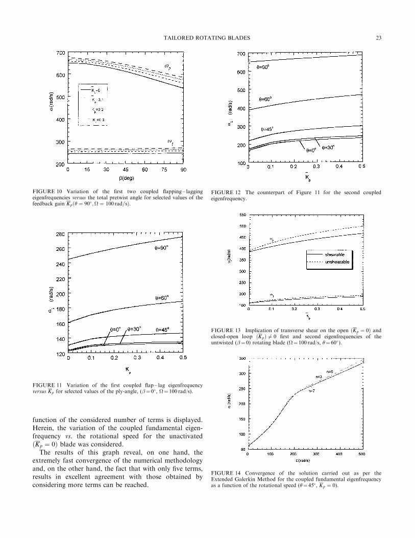
function of the considered number of terms is displayed.
Herein, the variation of the coupled fundamental eigen-
frequency vs. the rotational speed for the unactivated
�Kp � 0� blade was considered.The results of this graph reveal, on one hand, the
extremely fast convergence of the numerical methodology
and, on the other hand, the fact that with only ®ve terms,
results in excellent agreement with those obtained by
considering more terms can be reached.
FIGURE 10 Variation of the ®rst two coupled ¯apping ± laggingeigenfrequencies versus the total pretwist angle for selected values of thefeedback gain Kp�� � 90�; � 100 rad=s�.
FIGURE 11 Variation of the ®rst coupled ¯ap ± lag eigenfrequencyversus Kp for selected values of the ply-angle, (�� 0�, � 100 rad/s).
FIGURE 12 The counterpart of Figure 11 for the second coupledeigenfrequency.
FIGURE 13 Implication of transverse shear on the open �Kp � 0� andclosed-open loop �Kp� 6� 0 ®rst and second eigenfrequencies of theuntwisted (�� 0) rotating blade (� 100 rad/s, �� 60�).
FIGURE 14 Convergence of the solution carried out as per theExtended Galerkin Method for the coupled fundamental eigenfrequencyas a function of the rotational speed (�� 45�, Kp � 0).
23TAILORED ROTATING BLADES
CONCLUDING REMARKS
A dynamical theory of rotating composite blades modeled
as thin-walled beams of arbitrary cross-section obtained
via the Hamilton's variational principle was supplied.
The theory incorporates a number of non-classical
features which are essential for a reliable prediction of free
vibration characteristics of advanced rotating composite
blades. Among others, the theory includes transverse shear,
rotatory inertia, anistropy of constituent materials of the
host structure, pretwist, and the adaptive control cap-
ability. The strong and synergistic e�ect played by the
directionality property of advanced composite materials
considered in conjunction with that of structural pretwist
and piezoelectric actuation on their dynamic response
characteristics was highlighted.
A powerful and robust solution methodology was used
to determine both the open and closed-loop free vibration
response characteristics of rotating blades.
It is hoped that in addition to the information provided,
the paper can constitute a good basis for further investiga-
tion on parametric instability, dynamic response to time-
dependent loads, e�ect of a high temperature ®eld, and
aeroelastic ¯utter instability of blades modeled as thin-
walled beams. Such a comprehensive approach of the
problem will contribute to the enhancement of the dynamic
behavior of these structures, and will ensure the accom-
plishment of a better design as to avoid the occurence of
catastrophic failures of rotor blades (see Srinivasan, 1997).
REFERENCES
Berlincourt, D. A., Curran, D. R. and Ja�e, H. (1964) ``Piezoelectric andPiezomagnetic Materials and Their Function in Transducers'', PhysicalAcoustics ± Principles and Methods (Ed. Mason, E. F.), Vol. 1, Pt. A,Academic Press, New York, pp. 202 ± 204.
Crawley, E. F. (1994) ``Intelligent Structures for Aerospace; a TechnologyOverview and Assessment'', AIAA Journal, 32(8), 1689 ± 1699.
Dokumiaci, E., Thomas, J. and Carnegie, W. (1967) ``Matrix Displace-ment Analysis of Coupled Bending ±Bending Vibrations of PretwistedBlading'', Journal Mechanical Engineering Science, 9(4), 247 ± 254.
Dosch, J. J., Inman, D. J. and Garcia, E. (1992) ``A Self-sensingPiezoelectric Actuator for Collocated Control'', Journal of IntelligentMaterial Systems and Structures, 3(1), 166 ± 184.
Ewins, D. J. and Henry, R. (1992) ``Structural Dynamic Characteristics ofIndividual Blades'', Vibration and Rotor Dynamics, Von K�arm�anInstitute for Fluid Dynamics, Lecture Series 1992 ± 06, pp. 14.1 ± 14.27.
Kosmatka, J. B. (1992) ``Extension-bend-twist Coupling Behavior of Non-homogeneous Anisotropic Beams with Initial Twist'', AIAA Journal,30(2), 519 ± 527.
Librescu, L., Meirovitch, L. and Song, O. (1996) ``Integrated StructuralTailoring and Control Using Adaptive Materials for Advanced AircraftWings'', Journal of Aircraft, 33(1), Jan. ± Feb., 203 ± 213.
Librescu, L., Meirovitch, L. and Na, S. S. (1997) ``Control of CantileverVibration via Structural Tailoring and Adaptive Materials'', AIAAJournal, 35(8) 1309 ± 1315.
Librescu, L. and Na, S. S. (1998) ``Boundary Control of Free and ForcedOscillation of Shearable Thin-walled Beam Cantilevers'', EuropeanJ. Mech. A/Solids, 17(4), 687 ± 700.
Librescu, L., Song, O. and Kwon, H. D. (1999) ``Vibration and StabilityControl of Gyroelatic Thin-walled Beams via Smart MaterialsTechnology'', Smart Structures, Holnicki-Szulk, J. and Rodellar, J.(Eds.), Kluwer Academic Publication, pp. 163 ± 172.
Librescu, L., Meirovitch, L. and Song, O. (1996) ``Re®ned StructuralModeling for Enhancing Vibrational and Aeroelastic Characteristics ofComposite Aircraft Wings'', La Recherche Aerospatiale, 1, 23 ± 35.
Rosen, A. (1991) ``Structural and Dynamic Behavior of Pretwisted Rodsand Beam'', Applied Mechanics Reviews 44(12), part 1, 483 ± 515.
Slyper, H. A. (1962) ``Coupled Bending Vibrations of PretwistedCantilever Beams'', Journal Mechanical Engineering Sciences, 4(4),365 ± 379.
Song, O. and Librescu, L. (1993) ``Free Vibration of AnisotropicComposite Thin-walled Beams of Closed Cross-section Contour'',Journal of Sound and Vibration, 167(1), 129 ± 147.
Song, O. and Librescu, L. (1997a) ``Modeling and Vibration of PretwistedSpinning Composite Thin-Walled Beams'', Proceedings of the 38thAIAA/ASME/ASCE/AHS/ASC Structures, Structural Dynamics,Materials Conference and Exhibition and AIAA/ASME/AHS/AdaptiveStructures Forum, Paper AIAA 97 ± 1091, Part 1, pp. 312 ± 322,Kissimmee, Florida, April 7 ± 10.
Song, O. and Librescu, L. (1997b) ``Structural Modeling and FreeVibration Analysis of Rotating Composite Thin-walled Beams'',Journal of the American Helicopter Society, 42(4), 358 ± 369.
Song, O. and Librescu, L. (1999) ``Modeling and Dynamic Behavior ofRotating Blades Carrying a Tip Mass and Incorporating AdaptiveCapabilities'', Acta Mechanica, 134, 169 ± 197.
Song, O. and Librescu, L. (1997c) ``Anisotropy and Structural Couplingon Vibration and Instability of Spinning Thin-walled Beams'', Journalof Sound and Vibration, 204(3), 477 ± 494.
Srinivasan, A. V. (1997) ``Flutter and Resonant Characteristics of EngineBlades'', Journal of Engineering for Gas Turbines and Power, Trans.ASME, 119, October, 742 ± 775.
Subrahmanyam, K. B., Kulkarni, S. V. and Rao, J. S. (1981) ``CoupledBending ±Bending Vibrations of Pretwisted Blading Allowing for ShearDeformation and Rotary Inertia by the Reissner Method'', Interna-tional Journal of Mechanical Sciences, 23(9), 517 ± 530.
Subrahmanyam, K. B. and Kaza, K. R. V. (1986) ``Vibration andBuckling of Rotating Pretwisted, Preconed Beams Including CoriolisE�ects'', Journal of Vibration, Acoustics, Stress and Reliability in Design,108, 140 ± 149.
Sunar, M. and Rao, S. S. (1994) ``Reent Advances in Sensing and Controlof Flexible Structures: via Piezoelectric Materials Technology'', AppliedMechanics Reviews, 52(1), 1 ± 16.
APPENDIX
The global sti�ness quantities including the pretwist e�ect
a22 � �m2ap22 � n2a
p33 ÿ 2mna
p23�;
a23 � mn�ap22 ÿ ap33�
a25 � a52 � �m2ap25 ÿ n2a
p34 �mn�ap24 ÿ a
p35��;
a33 � �m2ap33 � n2a
p22 � 2mna
p23�
a34 � a43 � �m2ap34 ÿ n2a
p25 �mn�ap24 ÿ a
p35��;
a44 � �m2ap44 � n2a
p55 ÿ 2mna
p45�
a45 � mn�ap44 ÿ ap55�;
a55 � �m2ap55 � n2a
p44 � 2mna
p54�
In addition, the mass terms are given by:
b1 � bp1; b4 � m2b
p4 � n2b
p5 � 2mnb
p6
24 O. SONG ET AL.

b5 � m2bp5 � n2b
p4 ÿ 2mnb
p6;
b6 � mn�bp5 ÿ bp4�; b13 � mn�bp14 ÿ b
p15�;
b14 � m2bp14 � n2b
p15 ÿ 2mnb
p13;
b15 � m2bp15 � n2b
p14 � 2mnb
p13:
In these expression, the quantities a�ected by superscript
p are associated with the beam cross-section referred to the
principal axes (xp, yp), whereas m(z) � cos�, n(z)� sin �,where �� �(z). The expressions of sti�ness and mass terms
referred to principal axes can be found in the paper by
Song and Librescu (1997a).
25TAILORED ROTATING BLADES

International Journal of
AerospaceEngineeringHindawi Publishing Corporationhttp://www.hindawi.com Volume 2010
RoboticsJournal of
Hindawi Publishing Corporationhttp://www.hindawi.com Volume 2014
Hindawi Publishing Corporationhttp://www.hindawi.com Volume 2014
Active and Passive Electronic Components
Control Scienceand Engineering
Journal of
Hindawi Publishing Corporationhttp://www.hindawi.com Volume 2014
International Journal of
RotatingMachinery
Hindawi Publishing Corporationhttp://www.hindawi.com Volume 2014
Hindawi Publishing Corporation http://www.hindawi.com
Journal ofEngineeringVolume 2014
Submit your manuscripts athttp://www.hindawi.com
VLSI Design
Hindawi Publishing Corporationhttp://www.hindawi.com Volume 2014
Hindawi Publishing Corporationhttp://www.hindawi.com Volume 2014
Shock and Vibration
Hindawi Publishing Corporationhttp://www.hindawi.com Volume 2014
Civil EngineeringAdvances in
Acoustics and VibrationAdvances in
Hindawi Publishing Corporationhttp://www.hindawi.com Volume 2014
Hindawi Publishing Corporationhttp://www.hindawi.com Volume 2014
Electrical and Computer Engineering
Journal of
Advances inOptoElectronics
Hindawi Publishing Corporation http://www.hindawi.com
Volume 2014
The Scientific World JournalHindawi Publishing Corporation http://www.hindawi.com Volume 2014
SensorsJournal of
Hindawi Publishing Corporationhttp://www.hindawi.com Volume 2014
Modelling & Simulation in EngineeringHindawi Publishing Corporation http://www.hindawi.com Volume 2014
Hindawi Publishing Corporationhttp://www.hindawi.com Volume 2014
Chemical EngineeringInternational Journal of Antennas and
Propagation
International Journal of
Hindawi Publishing Corporationhttp://www.hindawi.com Volume 2014
Hindawi Publishing Corporationhttp://www.hindawi.com Volume 2014
Navigation and Observation
International Journal of
Hindawi Publishing Corporationhttp://www.hindawi.com Volume 2014
DistributedSensor Networks
International Journal of