dynamic design of hydraulic pressure … · dynamic design of hydraulic pressure control valve of...
TRANSCRIPT

DYNAMIC DESIGN OF HYDRAULIC PRESSURE CONTROL VALVE OF ACTIVE SUSPENSION SYSTEM USING EXPERIMENTAL METHOD
Choon-Tae Lee1 and Byung-Young Moon2*
1 Department of Automotive Mechanical Engineering, Silla University, Pusan, Korea
2 Department of Naval Architecture, Kunsan National University, Kunsan, Korea
* Corresponding author ([email protected])
ABSTRACT: The controllability of active suspension system in automotive vehicle is strongly affected by the performance
of pressure control valve. In this study, a new mathematical model and simulation model of the hydraulic pressure control
valve of automotive is proposed. And proposed model of the hydraulic pressure control valve are analyzed. The effects of
the main design parameters variations on the performance of the pressure control valve are investigated. To show the
effectiveness of the proposed mathematical and simulation model, the analyzed results are compared with the experimental
results. As a result, the proposed model of the hydraulic pressure control valve was proved as very effective one. The results
reported herein will provide a better understanding of the automotive active suspension system. Moreover, it is believed that
those properties of the results can be utilized in the dynamic design of the automotive system. It is believed that these
studies can be contributed in automobile suspension system.
Keywords: Hydraulic Mechanics, Mathematical Model, Design of Servo System, Signal Processing, Hydraulic Valve,
Active Suspension System, Vehicle Dynamics
1. INTRODUCTION
Recently, due to the increased advances of electronics
technology and integration with hydraulic technology,
active control technology has been adapted to the chassis
system [1, 2]. An Active Suspension system is a system
which has an external hydraulic energy source and controls
each wheel's suspension load by supplying or discharging
the hydraulic energy in order to obtain both good handling
and ride comfort. In order to actively and instantly restrain
or control undesired movements generated by the vehicle
vibrations and inclinations, it is necessary for the vehicle
itself to provide a power source which can always supply
energies necessary for controlling. On the other hand,
running on a smooth road such as a highway, the vibrations
or attitude changes of vehicle do not occur so often and not
much energy is needed. At first, a Full Active Suspension
system with high frequency response which uses hydraulic
cylinders was investigated to verify the potentiality of
performance. However, such a system is not suitable for
practical use, because it wastes much energy to obtain
equivalent performance of ride comfort to the passive
suspension system in high frequency range, and needs the
high performance actuators which are very expensive.
However a Slow Active Suspension was developed as a
practical system which mainly controls the motions of low
frequency range and the performance in high frequency
range depends upon its passive characteristics [3]. The
Active Suspension system for a passenger car has four
functions - ride comfort control, vehicle attitude control,
height control and stability control. These functions are
carried out by controlling hydraulic pressure in the hydro-
pneumatic cylinders which have gas springs supporting
each wheel. In the relatively low frequency band or less
than 2Hz, the pressure control valve receives pressure
supply and discharge signals from the electric sensors, such
as a G-sensor and controls in the system. In the
intermediate frequency band of 2~6Hz, a spool valve in the
P2-14
1434
pressure control valve senses the pressure changes and
mechanically operates to keep the line pressure constant,
thereby preventing the transmission of vibrations to the
vehicle body[4,5].
2. SYSTEM MODELING
The mathematical modeling of the proportional pressure control valve
A pressure control valve in the integrated valve unit
controls high pressure to necessary levels and supplies
pressure to each hydro-pneumatic cylinder or returns the
oil in the hydro-pneumatic cylinders to a reservoir tank to
always keep the necessary the pressure in the hydraulic
cylinder. The simplified structure of the quarter car
hydraulic model for the active suspension system is shown
in Fig. 1.
Fig. 1 The active suspension system hydraulic circuit
(quarter car)
It is composed of a hydraulic pump, a valve, a
hydraulic actuator and an accumulator. The valve which
has been developed for the Active Suspension is a
proportional pressure control valve type, because the
electric current which supplied to the solenoid coil of the
proportional pressure control valve controls the hydraulic
pressures linearly in the hydro-pneumatic strut. The
proportional pressure control valve is consist of the
solenoid valve portion for generating power, the poppet
valve portion for generating pilot pressure, and the spool
valve portion for switching over hydraulic passages. The
solenoid force is transmitted to the poppet valve to balance
the pressure in the pilot pressure chamber. It means that the
pressure in the pilot pressure chamber is determined by the
solenoid force, i.e., the electric current value of the
solenoid coil. The pressure of the pilot pressure chamber
and outlet port are equalized by introducing the pressure in
the pilot pressure chamber into the spool valve at one end
and the pressure in the outlet port into the spool valve at
the other end, thereby to obtain the same level pressure in
the outlet port as that in the pilot pressure chamber, which
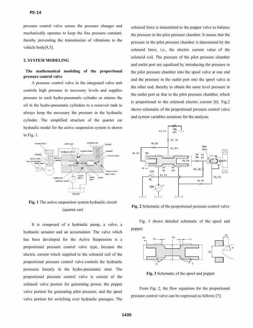
is proportional to the solenoid electric current [6]. Fig.2
shows schematic of the proportional pressure control valve
and system variables notations for the analysis.
Fig. 2 Schematic of the proportional pressure control valve
Fig. 3 shows detailed schematic of the spool and
poppet.
Fig. 3 Schematic of the spool and poppet
From Fig. 2, the flow equations for the proportional
pressure control valve can be expressed as follows [7];
P2-14
1435

312
11 PPAdCiQ
(1)
03222
PPACQ do
(2)
622
PPACQ podpopo
(3)
212
PPACQ sds
(4)
5252
2PPsignPPACQ ppp
(5)
4343
2PPsignPPACQ fff
6)
062
PPACQ rrr
(7)
732
PPACQ ccc
(8)
072
PPACQ ththth
(9)
where, 1dC , 2dC , dpoC and dC ~ thC are the flow
coefficients of the orifices, sA is an area of the supply
orifice, pA is an area of the pilot orifice, poA is an area
of the poppet orifice, fA is an area of the feedback
orifice, rA is an area of the return orifice, cA is an area
of the control orifice, thA is an area of the throttle valve.
The sectional area of the spool ( 1A , 2A ) and the
poppet( poA ) can be expressed as follows;
if ns xx , 01 A (10)
if xxxx nsn ,
2sin2
))(()(sin1
xxxDxxxA ns
sns
(11)
if )( xxx ns , ))((1 xxxDA nss
(12)
]2sin2
[sin ppppo
xDxA (13)
The flow continuity equations for the proportional
pressure control valve can be expressed as follows;
011 dt
dPVQQQQ
osrifipp
(14)
022 dt
dPV
dt
dxAQQQ
o
ppopops
(15)
033 dt
dPVQQQ
ocfi
(16)
044 dt
dPV
dt
dxAQ
o
sspoolf
(17)
055 dt
dPV
dt
dxAQ
o
sspoolp
(18)
066 dt
dPV
dt
dxAQQ
o
pporpo
(19)
077 dt
dPVQQ
othc
(20)
where spoolA is an area of the spool and o is the bulk
modulus of oil. The dynamic equations of the spool and
poppet can be expressed as follows;
0)( 452
2
PPAFxKdt
dxC
dt
xdM sflsss
ss
ss
(21)
)]()([cos2 032311 PPACPPACF sosifls (22)
vdsi CCC 1 (23)
vdso CCC 2 (24)
0)( 622
2
spoflpp
pp
p FPPAFdt
dxC
dt
xdM (25)
)]([cos2 02 PPACF poprflp (26)
vpopr CCC (27)
where, sM , pM are the mass of the spool and poppet,
sC , pC are the viscous damping coefficients of the spool
and poppet, sK is the stiffness coefficient of the return
spring, flsF , flpF are the flow force of the spool and
poppet, vC is velocity coefficient, and cos , cos are
inflow angle.
3. The simulation results of the proportional pressure
control valve
A simulation model [8] of the proportional pressure
control valve is shown in Fig. 4. The main physical
properties of the simulation model are listed in the Table 1.
P2-14
1436

Table 1 Physical properties of the simulation
Constants Value
Density of oil 880 kg/m3
Bulk Modulus of elasticity of oil 1.8 x 10⁹ Pa
Mass of spool 1.2 x 10⁻³ kg
Mass of poppet 8.1 x 10⁻⁵ kg
Constant of feedback spring 6.47 x 10³ N/m
Area of poppet port 4.91 x 10⁻⁶ m2
Diameter of spool 10 mm
Overlap of spool 0.2 mm
Angle of spool = 50 deg, = 40 deg
Angle of poppet 20 deg
Diameter of supply orifice 0.3 mm
Diameter of pilot orifice 0.3 mm
Diameter of feedback orifice 0.3 mm
Diameter of return orifice 0.7 mm
Diameter of control orifice 2.5 mm
The simulation model is constructed by using the
AMESIM ver4.0 of Imagine Co.. It is composed of main
valve portion, pilot valve portion and solenoid portion,
respectively. Fig. 5 shows the typical simulation results of
the supply pressure ( 1P ), return pressure ( 6P ) and outlet
pressure ( 7P ) for the solenoid current step input. The sign
is the same as that of Fig. 2. The dynamic response
characteristics of the valve have 310ms settled time (2%).
Fig. 6 shows the simulation results of spool displacement
( sx ) and poppet displacement ( px ) for the solenoid
current step input.
Fig. 4 Simulation model of the proportional pressure
control valve
0.00 0.05 0.10 0.15 0.20 0.25 0.30 0.35 0.40 0.450
2
4
6
8
10
12
return pressure (P6)
control pressure (P7)
prs
ss
ure
(M
pa
)
time (sec)
settle time = 310 msec supply pressure (P1)
Fig. 5 Simulation results of supply return and control
pressure for the solenoid current step input
0.00 0.05 0.10 0.15 0.20 0.25 0.30 0.35 0.40 0.45-3
-2
-1
0
1
2
3
Poppet displacement (xp)
dis
pla
ce
me
nt
(mm
)
time (sec)
Spool displacement (xs)
Fig. 6 Simulation results of spool and poppet displacement
for the solenoid current step input
4. The experimental results of the proportional
pressure control valve
P2-14
1437

Fig. 7 shows the schematic drawing of the
proportional pressure control valve and Fig. 8 shows the
photograph of the testing valve. Figure 9 shows Hydraulic
circuits for the proportional pressure control valve
performance test.
Fig. 7 Cross section of proportional pressure control valve
Fig. 8 Photograph of developed proportional pressure
control valve
Testing circuit is composed of a hydraulic pump, a
relief valve for controlling the pressure of system, a flow
meter for measuring the flow rate, a pressure transducer
which is strain gauge type for measuring the supply
pressure and the control pressure, a variable throttle valve
for hydraulic load, a data acquisition system for measuring
test results, and a personal computer for controlling electric
current input to the proportional pressure control valve.
The supply condition of the hydraulic pump is 12 lpm and
10.5 Mpa. The control pressure of system is set to 5 Mpa.
Fig. 9 Hydraulic circuits for the proportional pressure
control valve performance test
The experimental result of the static characteristics of
the proportional pressure control valve which is developed
in this study is shown in Fig. 10. It shows that there is a
dead zone where the pressure is not controlled despite
current is supplied to the solenoid, caused by frictional
force at the below 0.05A. The proportional pressure control
valve controls outlet pressure linearly in the range of
0~9,8Mpa, for the current 0~0.7A. This characteristics well
meets the performance required by Active Suspension
system and has good hysteresis characteristic which is
under 4.5%. The experimental result of the dynamic
response characteristics is shown in Fig. 11. The
experimental results shows the dynamic response of the
valve is 325msec on the basis of the settled time (2%). The
comparison between Fig. 5 and Fig. 11 shows about
15msec discrepancy in settling time exists but the control
pressure is coincided with each other as 5Mpa. As a result,
the experimental results coincide with simulation results
well.
P2-14
1438

Fig. 10 Static characteristic of the developed valve
(Experimental result)
0.0 0.1 0.2 0.3 0.40
2
4
6
8
10
12
control pressure (P7)
supply pressure (P1)
pre
ss
ure
(M
pa
)
time (sec)
settle time = 325 msec
Fig. 11 Dynamic response of the developed valve
(Experimental result)
5. Conclusion and Discussion
In this paper we understood the structure and principle,
simulated and experimented the static and dynamic
characteristics for development of the proportional control
valve which is an important part in the active suspension
system. The following results have been obtained form this
study.
(1) We proposed the mathematical and simulation model
of the proportional pressure control valve for the Active
Suspension system.
(2) It is confirmed that the simulation results are
coincided with the experimental results well.
(3) The proportional pressure control valve which has
good performance and suitable for applying to the Active
Suspension system has developed. Therefore, it is expected
that the valve developed in this study can be applicable for
more applications such as construction machinery and
other vehicle hydraulic control system.
References
[1] F. Gay, N. Coudert and I. Rifqi, Development of
Hydraulic Active Suspension with Feedforward and
Feedback Design, SAE 2000-01-0104
[2] J. Emura, S. Kakizaki, F. Yamaoka and M. Nakamura,
Development of the semi-active suspension system based
on the Sky-hook damper theory, SAE 940863, 1990
[3] G.P. Wright, and A.D. Williams, The Application of
Active Suspension to High Performance Road Vehicles,
Proc. Instn Mech. Engrs. Part D, 1990, 204, pp. 23-28.
[4] M. Sugihara, T. Furukawa, O. Komazawa, M. Okade,
Y. Yokoya and S. Buma, Development of Control Valves
for Active Suspension Systems-Development of Linear
Pressure Control Valve for Car, Proceeding of JSAE 1990-
10, 1990, pp. 361-364.
[5] H. Matsushita, T. Noritsugu and T. Wada, Optimal
Control of Active Air Suspension, Transactions of the
JSME, C, 1990, 56(526), pp. 1178-1183.
[6] B.H. Cho, J.S. Oh and W.H. Lee, Modeling of Pulse Width
Modulation Pressure Control System for Automatic Transmission,
SAE 2002-01-1257
[7] E.M. Herbert, Hydraulic Control Systems, John Wiley & Sons,
1967, pp. 76-131.
[8] V. Nanda and V. Subbarao, Computer Modeling and
Simulation of Hydraulic Systems, SAE 981978
P2-14
1439