dynamic energy unit deu-st - moog inc. · 2020-06-25 · 2 connection terminal deu-em (x1) 7 eia422...
TRANSCRIPT

What moves your World
DYNAMIC ENERGY UNIT DEU-STMANAGING bRAkING ENERGY
OperatiOn manualrev. B, april 2014

2Ver. B, march 2014
moog Dynamic energy unit
taale oof ooteots
intrODuctiOn
1 intrODuctiOn
1.1 preface . . . . . . . . . . . . . . . . . . . . . . . . . . . . . . . . . . . . . . . . . . . . . . . . . . . . . . . . . . . . . . . . . . . . . . . . . . . . . . . . . . . . . . . . . . . . . . . . . . . . . . . . . . . . 4
1.2 environmental protection . . . . . . . . . . . . . . . . . . . . . . . . . . . . . . . . . . . . . . . . . . . . . . . . . . . . . . . . . . . . . . . . . . . . . . . . . . . . . . . . . . . . . . . . . 4
1.3 Working with this Operation manual . . . . . . . . . . . . . . . . . . . . . . . . . . . . . . . . . . . . . . . . . . . . . . . . . . . . . . . . . . . . . . . . . . . . . . . . . . . . . 4
1.3.1 target group . . . . . . . . . . . . . . . . . . . . . . . . . . . . . . . . . . . . . . . . . . . . . . . . . . . . . . . . . . . . . . . . . . . . . . . . . . . . . . . . . . . . . . . . . . . . . . . . . . . . . 4
1.3.2 Basic information . . . . . . . . . . . . . . . . . . . . . . . . . . . . . . . . . . . . . . . . . . . . . . . . . . . . . . . . . . . . . . . . . . . . . . . . . . . . . . . . . . . . . . . . . . . . . . . 4
1.3.3 abbreviations . . . . . . . . . . . . . . . . . . . . . . . . . . . . . . . . . . . . . . . . . . . . . . . . . . . . . . . . . . . . . . . . . . . . . . . . . . . . . . . . . . . . . . . . . . . . . . . . . . . . 4
1.3.4 Symbols . . . . . . . . . . . . . . . . . . . . . . . . . . . . . . . . . . . . . . . . . . . . . . . . . . . . . . . . . . . . . . . . . . . . . . . . . . . . . . . . . . . . . . . . . . . . . . . . . . . . . . . . . 5
1.3.5 Definitions . . . . . . . . . . . . . . . . . . . . . . . . . . . . . . . . . . . . . . . . . . . . . . . . . . . . . . . . . . . . . . . . . . . . . . . . . . . . . . . . . . . . . . . . . . . . . . . . . . . . . . . 5
2 DeVice DeScriptiOn
2.1 intended use . . . . . . . . . . . . . . . . . . . . . . . . . . . . . . . . . . . . . . . . . . . . . . . . . . . . . . . . . . . . . . . . . . . . . . . . . . . . . . . . . . . . . . . . . . . . . . . . . . . . . . 6
2.2 applied regulations . . . . . . . . . . . . . . . . . . . . . . . . . . . . . . . . . . . . . . . . . . . . . . . . . . . . . . . . . . . . . . . . . . . . . . . . . . . . . . . . . . . . . . . . . . . . . . . 6
2.3 type designation . . . . . . . . . . . . . . . . . . . . . . . . . . . . . . . . . . . . . . . . . . . . . . . . . . . . . . . . . . . . . . . . . . . . . . . . . . . . . . . . . . . . . . . . . . . . . . . . . . 6
2.4 Overview . . . . . . . . . . . . . . . . . . . . . . . . . . . . . . . . . . . . . . . . . . . . . . . . . . . . . . . . . . . . . . . . . . . . . . . . . . . . . . . . . . . . . . . . . . . . . . . . . . . . . . . . . . . 7
2.5 nameplate . . . . . . . . . . . . . . . . . . . . . . . . . . . . . . . . . . . . . . . . . . . . . . . . . . . . . . . . . . . . . . . . . . . . . . . . . . . . . . . . . . . . . . . . . . . . . . . . . . . . . . . . . 7
2.6 labels on the housing . . . . . . . . . . . . . . . . . . . . . . . . . . . . . . . . . . . . . . . . . . . . . . . . . . . . . . . . . . . . . . . . . . . . . . . . . . . . . . . . . . . . . . . . . . . . 8
2.7 ambient conditions . . . . . . . . . . . . . . . . . . . . . . . . . . . . . . . . . . . . . . . . . . . . . . . . . . . . . . . . . . . . . . . . . . . . . . . . . . . . . . . . . . . . . . . . . . . . . . . 8
2.8 electrical connection values . . . . . . . . . . . . . . . . . . . . . . . . . . . . . . . . . . . . . . . . . . . . . . . . . . . . . . . . . . . . . . . . . . . . . . . . . . . . . . . . . . . . . . 8
2.9 Size and weight . . . . . . . . . . . . . . . . . . . . . . . . . . . . . . . . . . . . . . . . . . . . . . . . . . . . . . . . . . . . . . . . . . . . . . . . . . . . . . . . . . . . . . . . . . . . . . . . . . . 9
2.10 noise emissions . . . . . . . . . . . . . . . . . . . . . . . . . . . . . . . . . . . . . . . . . . . . . . . . . . . . . . . . . . . . . . . . . . . . . . . . . . . . . . . . . . . . . . . . . . . . . . . . . 9
3 BaSic Safety inStructiOnS
3.1 personnel . . . . . . . . . . . . . . . . . . . . . . . . . . . . . . . . . . . . . . . . . . . . . . . . . . . . . . . . . . . . . . . . . . . . . . . . . . . . . . . . . . . . . . . . . . . . . . . . . . . . . . . . .10
3.2 Device . . . . . . . . . . . . . . . . . . . . . . . . . . . . . . . . . . . . . . . . . . . . . . . . . . . . . . . . . . . . . . . . . . . . . . . . . . . . . . . . . . . . . . . . . . . . . . . . . . . . . . . . . . . .10
4 tranSpOrt/StOrage/inStallatiOn
4.1 checking the delivery . . . . . . . . . . . . . . . . . . . . . . . . . . . . . . . . . . . . . . . . . . . . . . . . . . . . . . . . . . . . . . . . . . . . . . . . . . . . . . . . . . . . . . . . . . . .11
4.2 transporting the Deu-St . . . . . . . . . . . . . . . . . . . . . . . . . . . . . . . . . . . . . . . . . . . . . . . . . . . . . . . . . . . . . . . . . . . . . . . . . . . . . . . . . . . . . . . .11
4.3 Storing the Deu-St . . . . . . . . . . . . . . . . . . . . . . . . . . . . . . . . . . . . . . . . . . . . . . . . . . . . . . . . . . . . . . . . . . . . . . . . . . . . . . . . . . . . . . . . . . . . . .11
4.4 unpacking the Deu-St . . . . . . . . . . . . . . . . . . . . . . . . . . . . . . . . . . . . . . . . . . . . . . . . . . . . . . . . . . . . . . . . . . . . . . . . . . . . . . . . . . . . . . . . . . .11
4.5 installing the Deu-St . . . . . . . . . . . . . . . . . . . . . . . . . . . . . . . . . . . . . . . . . . . . . . . . . . . . . . . . . . . . . . . . . . . . . . . . . . . . . . . . . . . . . . . . . . . .12
4.6 grounding the Deu-St . . . . . . . . . . . . . . . . . . . . . . . . . . . . . . . . . . . . . . . . . . . . . . . . . . . . . . . . . . . . . . . . . . . . . . . . . . . . . . . . . . . . . . . . . . .13
3Ver. B, march 2014
moog Dynamic energy unitintrODuctiOn
5 Setting up the DeVice
5.1 connecting the Deu-St . . . . . . . . . . . . . . . . . . . . . . . . . . . . . . . . . . . . . . . . . . . . . . . . . . . . . . . . . . . . . . . . . . . . . . . . . . . . . . . . . . . . . . . . . .14
5.2 connecting two or more Deu-St in parallel . . . . . . . . . . . . . . . . . . . . . . . . . . . . . . . . . . . . . . . . . . . . . . . . . . . . . . . . . . . . . . . . . . . .16
5.3 connecting two or more applications with a Dc link connection to a Deu-St . . . . . . . . . . . . . . . . . . . . . . . . . . . . . . .16
5.4 connecting the eia422 communication interface . . . . . . . . . . . . . . . . . . . . . . . . . . . . . . . . . . . . . . . . . . . . . . . . . . . . . . . . . . . . . .17
5.5 Disconnecting the Deu-St . . . . . . . . . . . . . . . . . . . . . . . . . . . . . . . . . . . . . . . . . . . . . . . . . . . . . . . . . . . . . . . . . . . . . . . . . . . . . . . . . . . . . . .18
5.6 forming the Deu-St . . . . . . . . . . . . . . . . . . . . . . . . . . . . . . . . . . . . . . . . . . . . . . . . . . . . . . . . . . . . . . . . . . . . . . . . . . . . . . . . . . . . . . . . . . . . .19
6 Other actiVitieS
6.1 cleaning the Deu-St. . . . . . . . . . . . . . . . . . . . . . . . . . . . . . . . . . . . . . . . . . . . . . . . . . . . . . . . . . . . . . . . . . . . . . . . . . . . . . . . . . . . . . . . . . . . .20
6.2 maintaining the Deu-St . . . . . . . . . . . . . . . . . . . . . . . . . . . . . . . . . . . . . . . . . . . . . . . . . . . . . . . . . . . . . . . . . . . . . . . . . . . . . . . . . . . . . . . . .20
6.3 repairing the Deu-St . . . . . . . . . . . . . . . . . . . . . . . . . . . . . . . . . . . . . . . . . . . . . . . . . . . . . . . . . . . . . . . . . . . . . . . . . . . . . . . . . . . . . . . . . . .20
6.4 Disposing of the Deu-St . . . . . . . . . . . . . . . . . . . . . . . . . . . . . . . . . . . . . . . . . . . . . . . . . . . . . . . . . . . . . . . . . . . . . . . . . . . . . . . . . . . . . . . .20
7 expanSiOn mODule Deu-em (OptiOn)
7.1 technical data . . . . . . . . . . . . . . . . . . . . . . . . . . . . . . . . . . . . . . . . . . . . . . . . . . . . . . . . . . . . . . . . . . . . . . . . . . . . . . . . . . . . . . . . . . . . . . . . . . . .21
7.2 transport/storage/installation . . . . . . . . . . . . . . . . . . . . . . . . . . . . . . . . . . . . . . . . . . . . . . . . . . . . . . . . . . . . . . . . . . . . . . . . . . . . . . . . . . .21
7.3 connecting an expansion module to the Deu-St . . . . . . . . . . . . . . . . . . . . . . . . . . . . . . . . . . . . . . . . . . . . . . . . . . . . . . . . . . . . . .21
7.4 connecting an additional expansion module . . . . . . . . . . . . . . . . . . . . . . . . . . . . . . . . . . . . . . . . . . . . . . . . . . . . . . . . . . . . . . . . . . . .23
7.5 Disconnecting the expansion module . . . . . . . . . . . . . . . . . . . . . . . . . . . . . . . . . . . . . . . . . . . . . . . . . . . . . . . . . . . . . . . . . . . . . . . . . . .24
7.6 Other activities . . . . . . . . . . . . . . . . . . . . . . . . . . . . . . . . . . . . . . . . . . . . . . . . . . . . . . . . . . . . . . . . . . . . . . . . . . . . . . . . . . . . . . . . . . . . . . . . . .24

4Ver. B, march 2014
moog Dynamic energy unit
1. Iotrodu tIoo
intrODuctiOn
1.1 Prefaceyou have chosen a forward-looking energy technology from moog. thank you for choosing a moog product. as a system provider, we set reliable standards in energy technology with innovative products. With the certification of our environmental management program according to emaS iii and our quality management system according to Din en iSO 9001:2008, we are committed to maintaining a sustainable corporate culture.
1.2 environmental protectionpackaging the packaging consists of environmentally friendly materials and can be disposed of through
municipal waste disposal facilities.
Devices moog takes back faulty devices and devices that are no longer in use.
1.3 Working with this operation manual
1.3.1 target groupthis Operation manuall is directed toward qualified electricians who will be working with the Dynamic energy unit Deu-St throughout its lifecycle.
1.3.2 aasic informationthis Operation manual is subdivided into individual sections.
please note the following:
• Before using the Deu-St, read this Operation manual carefully in its entirety. it will be too late to do so if the device is already in use.
• make every effort to understand the Operation manual completely. this is the only way to ensure that the Deu-St can be operated safely and as intended.
• always follow the instructions specified in the Operation manual.• Store this Operation manual in the vicinity of the device. the storage location must be known.
1.3.3 abbreviationsBgV Berufsgenossenschaftliche Vorschrift (Occupational health and Safety regulations) Deu-St Dynamic energy unit eeprOm electrical eraseable programmable read Only memory ec european community Deu-em expansion module en european norm leD light-emitting diode plc programmable logic controller

5Ver. B, march 2014
moog Dynamic energy unit intrODuctiOn
1.3.4 symbolscross-reference a cross-reference to another page in this Operation manual begins with the double arrow
symbol "".
action and reaction the symbol "" indicates an action taken by personnel, while the symbol "" indicates the reaction of the device to this action. example: Switch on the main switch. the lamp lights up.
image labels and important details in the graphics are identified with numbers (e.g. ). image-text association in the text, this number is located after the description of the detail it identifies.
1.3.5 definitionsSafety instructions a safety instruction consists of several parts:
• a pictogram,• a signal word that indicates the degree of danger,• a text indicating the type of danger and• information on how to avoid the danger, indicated by the symbol "".
Pictogram Signal word Danger Consequence
Danger indicates an imminent danger to persons (danger to life).
Death or very serious injury.
Warning indicates a potential danger to persons or property (danger of injury).
Damage to health or serious property damage.
caution indicates a potential danger to property (danger of property damage).
property damage.
example of a safety instruction:
WARNING!
Danger of injury! touching of hot surfaces may lead to burn injuries. Before cleaning, switch off the device for at least 30 minutes.
Other notes notes regarding events that do not involve personal or property damage are used as follows:
Pictogram Note
note regarding additional instructions or other useful information.
note regarding proper disposal.
application in this Operation manual, "application" refers to a "drive unit with a frequency converter" or a "servo drive".

6Ver. B, march 2014
moog Dynamic energy unit DeScriptiOn Of the DeVice
2. des rIPtIoo oof the devI e
2.1 Intended useDevice (Deu-St) the Dynamic energy unit (Deu-St) is used to store braking energy from applications (drives
with a frequency converter or servo drives). the Deu-St does not require a separate power supply. it is possible to operate multiple Deu-St in parallel to increase maximum power. to increase the energy storage capacity, it is also possible to connect optional expansion modules (Deu-em). the Deu-St is delivered on a customer-specific basis and may only be operated under adherence to these specifications.
expansion module the expansion module (Deu-em) is connected to the Deu-St and increases the energy (Deu-em) storage capacity of the Deu-St.
if multiple Deu-St are connected in parallel, the additional Deu-em units must be distributed symmetrically.
Safeguards the safeguards (e.g. cover) must not be removed.
area of use the area of use of the Deu-St is inside electrical switching cabinets in industrial facilities. it is not permissible to operate these devices in potentially explosive areas.
modifications it is not permissible to modify the device without authorization. Doing so will render the warranty and any liability claims invalid.
maintenance maintenance work may only be performed by the manufacturer.
2.2 applied regulationsthe Deu-St meets the basic requirements of low Voltage Directive 2006/95/ec and emc Directive 2004/108/ec.
2.3 type designationDynamic energy unit Deu-St cB33257-001
expansion module cB33255-001 (Deu-em 2.0) Deu-em cB33255-002 (Deu-em 4.0)
7Ver. B, march 2014
moog Dynamic energy unitDeScriptiOn Of the DeVice
2.4 overview
�
�
�
��
�
��
�
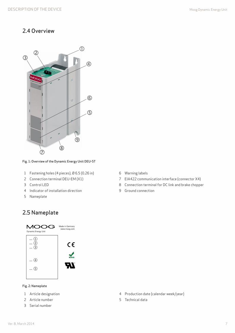
ofig. 1: overview of the dynamic energy unit deu-st
1 fastening holes (4 pieces), Ø 6.5 (0.26 in) 6 Warning labels2 connection terminal Deu-em (x1) 7 eia422 communication interface (connector x4)3 control leD 8 connection terminal for Dc link and brake chopper4 indicator of installation direction 9 ground connection5 nameplate
2.5 oameplate
Made in Germany
www.moog.com
DEU-SU CB33256-001 D000100
KW 05/2012
UZK: 500 – 800VDC +/- 10% TAMB: 0 – 40°C Imax: 20 A
Dynamic Energy Unit
… ① … ② … ③ … ④ … ⑤
ofig. 2: oameplate
1 article designation 4 production date (calendar week/year)2 article number 5 technical data3 Serial number
8Ver. B, march 2014
moog Dynamic energy unitDeScriptiOn Of the DeVice
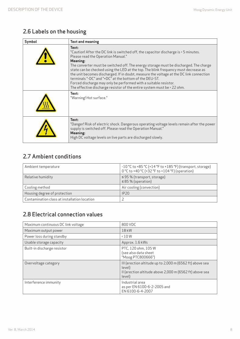
2.6 labels on the housingSymbol Text and meaning
Text:"caution! after the Dc link is switched off, the capacitor discharge is > 5 minutes. please read the Operation manual." Meaning: the converter must be switched off. the energy storage must be discharged. the charge state can be checked using the leD at the top. the blink frequency must decrease as the unit becomes discharged. if in doubt, measure the voltage at the Dc link connection terminals "-Dc" and "+Dc" at the bottom of the Deu-St. forced discharge may only be performed with a suitable resistor. the effective discharge resistor of the entire system must be > 22 ohm.Text: "Warning! hot surface."
Text: "Danger! risk of electric shock. Dangerous operating voltage levels remain after the power supply is switched off. please read the Operation manual." Meaning: high Dc voltage levels on live parts are discharged slowly.
2.7 ambient conditionsambient temperature -10 °c to +85 °c (+14 °f to +185 °f) (transport, storage)
0 °c to +40 °c (+32 °f to +104 °f) (operation)relative humidity ≤ 95 % (transport, storage)
≤ 85 % (operation)cooling method air cooling (convection)housing degree of protection ip20contamination class at installation location 2
2.8 electrical connection valuesmaximum continuous Dc link voltage 800 VDcmaximum output power 18 kWpower loss during standby < 10 Wusable storage capacity approx. 1.6 kWsBuilt-in discharge resistor ptc, 120 ohm, 105 W
(see also data sheet "moog ptc800666")
Overvoltage category iii (erection altitude up to 2,000 m (6562 ft) above sea level) ii (erection altitude above 2,000 m (6562 ft) above sea level)
interference immunity industrial area as per en 6100-6-2-2005 and en 6100-6-4-2007

9Ver. B, march 2014
moog Dynamic energy unitDeScriptiOn Of the DeVice
2.9 size and weightWidth 100 mm (3.94 in)Depth 201 mm (7.91 in)height 300 mm (11.81 in)Weight approx. 6.9 kg (15.21 lb)
2.10 ooise emissionsthe Deu-St does not create appreciable noise emissions (< 70 dB (a)).

10Ver. B, march 2014
moog Dynamic energy unit Safety inStructiOnS
3.1 Personnelminimum age not defined.
Duty of care the personnel must:
• Be qualified electricians.• have read and understood the Operation manual.• Be instructed in how the Deu-St functions.• Know how to perform the individual tasks.
conduct in case the following points must be adhered to: of an emergency
• the locations of the first aid stations must be known.• personnel must be informed about how to conduct themselves in case of an emergency.• proper conduct must be checked regularly and recorded accordingly.
in an emergency:
• perform first aid on the injured person.• call a doctor or the company medic.• inform the superiors.• follow the instructions of superiors or support staff.
3.2 devicefunctional state the Deu-St is only permitted to be operated when it is fully functional. Before using the
device, ensure that the Deu-St is in proper condition.
hot surfaces the device may reach temperatures up to +80 °c (+176 °f) during operation. Do not touch the housing.
Warning symbols Warning symbols are attached to the housing. Damaged warning symbols must be replaced immediately.
housing the housing is not permitted to be opened.
malfunctions electrical devices that could influence the function of the Deu-St are not permitted to be used in the vicinity of the Deu-St. the Deu-St is not permitted to be exposed to mechanical shock or vibrations.
3. aasI saofety Iostru tIoos

11Ver. B, march 2014
moog Dynamic energy unit tranSpOrt/StOrage/inStallatiOn
4. traosPort/storaGe/IostallatIoo
4.1 hecking the deliverythe Deu-St leaves the factory after it is checked and found to be in perfect condition. Special packaging consisting of a carton, corrugated cardboard and protective film ensures that the device can be transported safely. a packaging label is found on the outside of the packaging. note the instructions on transport, storage and appropriate handling. transport damage is the responsibility of the shipping company.
Scope of supply • 1 × Dynamic energy unit Deu-St • 1 × Dynamic energy unit Deu-St Operation manual • 1 × Built-in Brake resistor Data Sheet (order-specific) the exact scope of delivery is shown on the delivery slip.
check the delivery: check the packaging for damage. immediately notify the shipping company of damage on the packaging and/or on the
Deu-St. the damage notification must be received by the shipping company in writing within
seven days.
4.2 transporting the deu-st transport the Deu-St to the installation location in its original packaging. avoid strong vibrations and hard impacts.
4.3 storing the deu-st the Deu-St must be stored in clean, dry rooms.
temperatures between -10 °c and +85 °c (+14 °f and +185 °f)are permissible. temperature fluctuations must not exceed 30 K per hour.
4.4 unpacking the deu-st remove the Deu-St from the packaging carefully. check that the device is complete and undamaged. Dispose of the packaging in accordance with local regulations for cardboard and
recyclable materials.

12Ver. B, march 2014
moog Dynamic energy unittranSpOrt/StOrage/inStallatiOn
4.5 Installing the deu-st
CAUTION!
property damage! the Deu-St must not be installed upside down. install the Deu-St in an upright position.
Basic information • the Deu-St is designed for installation in an electrical switching cabinet. • the Deu-St must be protected by the switching cabinet against the penetration of foreign bodies. • the unit is installed directly on a mounting surface in the switching cabinet or on a base frame supply for this purpose by moog. • On account of the length of the connection cable (1 m (3.28 ft) maximum), the Deu-St must be installed directly next to the application (frequency converter, servo drive).
Distances Do not undercut the following distances to other modules when installing the unit: • Side: 20 mm (0.79 in) minimum • top and bottom: 100 mm (3.94 in) minimum
installation
ofig. 3: drilled hole template
install the Deu-St upright according to the drilled hole template using four screws (m6). the power connection is at the bottom.
check that it is firmly seated.

13Ver. B, march 2014
moog Dynamic energy unittranSpOrt/StOrage/inStallatiOn
4.6 Grounding the deu-st
ofig. 4: Ground connection (underside of housing)
ground the Deu-St at the ground connection (cross section according to the national standard). When using shielded lines, the shield must also be connected to the ground connection. perform a safety check as per BgV a3.
14Ver. B, march 2014
moog Dynamic energy unit Setting up the DeVice
WARNING!
Danger of injury! the housing may reach temperatures up to +80 °c (+176 °f) during operation. if work on the Deu-St should become necessary, wear heat-resistant gloves.
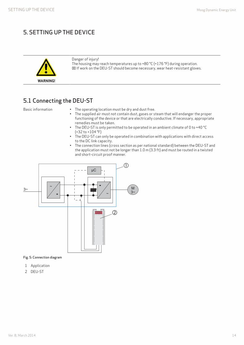
5.1 onnecting the deu-stBasic information • the operating location must be dry and dust free.
• the supplied air must not contain dust, gases or steam that will endanger the proper functioning of the device or that are electrically conductive. if necessary, appropriate remedies must be taken. • the Deu-St is only permitted to be operated in an ambient climate of 0 to +40 °c (+32 to +104 °f) • the Deu-St can only be operated in combination with applications with direct access to the Dc link capacity. • the connection lines (cross section as per national standard) between the Deu-St and the application must not be longer than 1.0 m (3.3 ft) and must be routed in a twisted and short-circuit proof manner.
ofig. 5: onnection diagram
1 application2 Deu-St
5. settIoG uP the devI e

15Ver. B, march 2014
moog Dynamic energy unit Setting up the DeVice
procedure
this procedure applies to the "automatic setting of the operating voltage in the Dc link". in case of a "fixed setting of the operating voltage in the Dc link", the brake resistor line is not connected.
CAUTION!
property damage! if a brake resistor is built into the application, the parallel circuitry with the brake resistor built into the Deu-St may cause the current flowing through the two brake resistors to become too large, resulting in the destruction of the brake transistor in the application. adhere to the Brake resistor Data Sheet "moog ptc800666". if necessary: adapt the application or contact moog gmbh.
ofig. 6: onnection terminals, underside of housing
Determine the polarity of the Dc link connections. De-energize the Dc link. establish that the Dc link is de-energized. remove the discharge bridge between terminals "–Dc" (black terminal) and "Br" (gray terminal). establish that no voltage is applied between terminals "–Dc" (black terminal) and "+Dc" (red terminal). connect the negative terminal on the Dc link output of the application with "–Dc" (black terminal) on the Deu-St. connect the brake chopper output of the application with "Br" (gray terminal) on the Deu-St. please note: this operation is not required for the "fixed setting of the operating voltage in the Dc link". connect the positive terminal on the Dc link output of the application with "+Dc" (red terminal) on the Deu-St.

16Ver. B, march 2014
moog Dynamic energy unit Setting up the DeVice
ofig. 7: ontrol led, top of housing
Supply the Dc link with voltage. the control leD on the top of the housing flashes after approx. 10 seconds (flashes more rapidly as the energy increases). the Deu-St is connected to the Dc link.
5.2 onnecting two or more deu-st in parallelit is also possible to connect multiple Deu-St units to the Dc link in parallel via the terminals "–Dc" (black terminal), "Br" (gray terminal) and "+Dc" (red terminal). proceed as described in ( Section 5.1).
5.3 onnecting two or more applications with a d link connection to a deu-st
Only one application has a brake resistor connect the Deu-St to this application. connect the brake resistor line to this application.
Multiple applications have a brake resistor and it is ensured that all applications always brake simultaneously connect the Deu-St to any application. Do not connect the brake resistor line (fixed presetting).
Multiple applications have a brake resistor and it is not ensured that all applications always brake simultaneously (only possible with DEU-ST with a fixed setting for the working voltage in the DC link) connect the Deu-St to any application. Do not connect the brake resistor line (fixed presetting).

17Ver. B, march 2014
moog Dynamic energy unit
5.4 onnecting the eIa422 communication interface
ofig. 8: underside of housing, eIa422 communication interface X4
Basic information • the communication interface is used to exchange data with the Deu-St. • the interface must be connected with an external eia422 communication interface.
connector x4 pin assignment
pin Signal Description1 rx+ connected with tx+ external interface2 rx- connected with tx- external interface3 gnD connected with gnD4 +24V connected with power supply +5...26 V5 tx+ connected with rx+ external interface6 tx- connected with rx- external interface
X4
RX-RX++ 5...26 VGNDTX-TX+
ofig. 9: onnector X4 pin assignment and external interface

18Ver. B, march 2014
moog Dynamic energy unit Setting up the DeVice
5.5 disconnecting the deu-stBasic information • as long as the energy storage of the Deu-St (with or without a Deu-em) is charged with
energy, it is not permissible to disconnect the Deu-St from the Dc link. this is indicated by the flashing control leD on the top of the housing. • to rule out that the control leD is malfunctioning, it is essential that you actually see the leD flashing before it goes out. this is the only way to ensure that it is safe to work on the Deu-St.
procedure
CAUTION!
property damage! the Deu-St may be destroyed when it is discharged using the supplied discharge bridge. When discharging using the supplied discharge bridge, ensure that the effective
resistance in the entire system is > 22 ohm.
ofig. 10: discharging the deu-st
Disconnect the application from the power supply. connect the discharge bridge between terminals "–Dc" (black terminal) and "Br" (gray terminal) on the Deu-St. the Deu-St is discharged. after the Deu-St is fully discharged, the control leD no longer flashes. after it is fully discharged, wait at least another 30 seconds. using a volt meter, establish that no voltage is applied between terminals "–Dc" (black terminal) and "+Dc" (red terminal). Disconnect the Deu-St from the Dc link. the discharge bridge remains connected as long as the Deu-St is disconnected from the Dc link. reconnect the application to the power supply.

19Ver. B, march 2014
moog Dynamic energy unit Setting up the DeVice
5.6 oforming the deu-stBasic information • if the Deu-St was without voltage for more than a year, it needs to be formed.
if this is not done, the Deu-St could be damaged when the power supply is switched on. • the production date is shown on the nameplate ( page 7, fig. 2).• When forming, the Deu-St is connected to the Dc link voltage but is not operational.
Spannungslose Zeit [Jahre]
Formierzeit [h]
5
4
3
2
1
1 2 3 4 5
ofig. 11: oforming time as a function of the voltage-free time
procedure connect the Deu-St to the Dc link ( Section 5.1, page 14). the Deu-St is formed (charged). allow the unit to be formed for a period that corresponds to the voltage-free time ( fig 11). after this, the application can be released.
forming time [h]
Voltage-free time [years]
20Ver. B, march 2014
moog Dynamic energy unit
6. other a tIvItIes
Other actiVitieS
6.1 leaning the deu-st
DANGER!
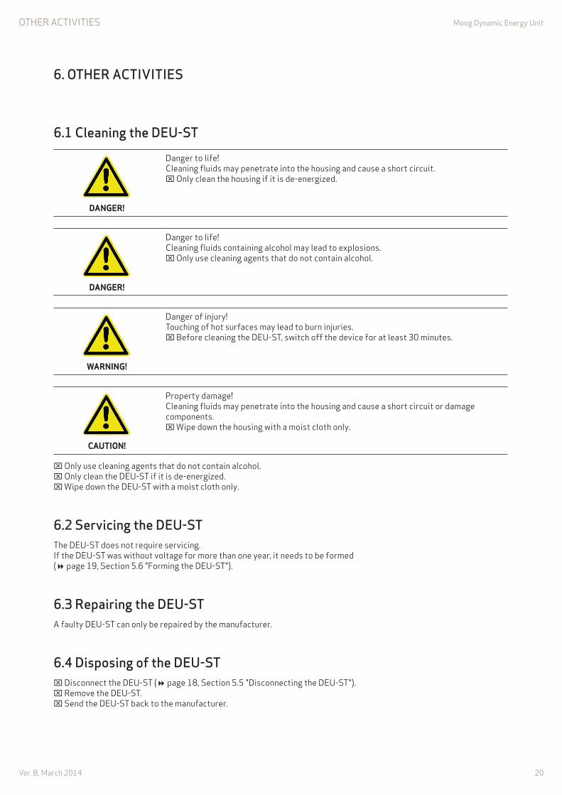
Danger to life! cleaning fluids may penetrate into the housing and cause a short circuit. Only clean the housing if it is de-energized.
DANGER!
Danger to life! cleaning fluids containing alcohol may lead to explosions. Only use cleaning agents that do not contain alcohol.
WARNING!
Danger of injury! touching of hot surfaces may lead to burn injuries. Before cleaning the Deu-St, switch off the device for at least 30 minutes.
CAUTION!
property damage! cleaning fluids may penetrate into the housing and cause a short circuit or damage components. Wipe down the housing with a moist cloth only.
Only use cleaning agents that do not contain alcohol. Only clean the Deu-St if it is de-energized. Wipe down the Deu-St with a moist cloth only.
6.2 servicing the deu-stthe Deu-St does not require servicing. if the Deu-St was without voltage for more than one year, it needs to be formed ( page 19, Section 5.6 "forming the Deu-St").
6.3 repairing the deu-sta faulty Deu-St can only be repaired by the manufacturer.
6.4 disposing of the deu-st Disconnect the Deu-St ( page 18, Section 5.5 "Disconnecting the Deu-St"). remove the Deu-St. Send the Deu-St back to the manufacturer.

21Ver. B, march 2014
moog Dynamic energy unitexpanSiOn mODule Deu-em (OptiOn)
7. eXPaosIoo module deu-em (oPtIoo)
the optionally available expansion module (Deu-em) increases the capacity of the energy storage of the Deu-St. it is supplied with a connection cable featuring connectors that are protected against polarity reversal.
7.1 technical dataambient conditions See Deu-St
( Section 2.7, page 8)usable storage capacity approx. 1.6 kWs cB33255-001 (Deu-em 2.0)
approx. 3.2 kWs cB33255-002 (Deu-em 4.0)Width 100 mm (3.94 in)Depth 201 mm (7.91 in)height 300 mm (11.81 in)Weight approx. 4.1 kg (9.03 lb) cB33255-001 (Deu-em 2.0)
approx. 6.2 kg (13.67 lb) cB33255-002 (Deu-em 4.0)
7.2 transport/storage/installationSee Deu-St ( Section 4, page 11)
7.3 onnecting an expansion module to the deu-st
CAUTION!
property damage! if the Deu-St is connected to the Dc link, this may destroy the expansion module. Before connecting the expansion module, disconnect the Deu-St from the Dc link
( page 18, "Disconnecting the Deu-St").
Disconnect the Deu-St from the Dc link ( page 18, "Disconnecting the Deu-St").
ofig. 12: discharging the expansion module (top of housing)
connect the supplied connection cable to x2 and x3 on the expansion module and wait approx. 30 seconds. the expansion module is discharged.
22Ver. B, march 2014
moog Dynamic energy unitexpanSiOn mODule Deu-em (OptiOn)
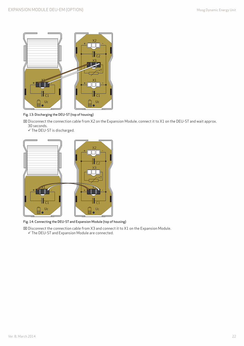
ofig. 13: discharging the deu-st (top of housing)
Disconnect the connection cable from x2 on the expansion module, connect it to x1 on the Deu-St and wait approx. 30 seconds. the Deu-St is discharged.
ofig. 14: onnecting the deu-st and expansion module (top of housing)
Disconnect the connection cable from x3 and connect it to x1 on the expansion module. the Deu-St and expansion module are connected.

23Ver. B, march 2014
moog Dynamic energy unitexpanSiOn mODule Deu-em (OptiOn)
7.4 onnecting an additional expansion module
ofig. 15: discharging the expansion module 2 (top of housing)
connect the supplied connection cable to x2 and x3 on the expansion module 2 and wait approx. 30 seconds. the expansion module 2 is discharged.
ofig. 16: discharging the expansion module 1 (top of housing)
Disconnect the connection cable from x2 on expansion module 2, connect expansion module 1 to x2 and wait approx. 30 seconds. the expansion module 1 is discharged.

24Ver. B, march 2014
moog Dynamic energy unitexpanSiOn mODule Deu-em (OptiOn)
ofig. 17: onnecting the deu-st and two expansion modules
Disconnect connection cable from x3 on the expansion module 2 and connect it with x2. the Deu-St and two expansion modules are connected.
7.5 disconnecting the expansion moduleSee Deu-St ( Section 5.5, page 18)
7.6 other activitiesSee Deu-St ( Section 6, page 20)

25Ver. B, march 2014
moog Dynamic energy unit
ootes
nOteS

26Ver. B, march 2014
moog Dynamic energy unit
ootes
nOteS

27Ver. B, march 2014
moog Dynamic energy unit
ootes
nOteS

What moves your World
argentina +54 11 4326 5916 [email protected]
australia +61 3 9561 6044 [email protected]
Brazil +55 11 3572 0400 [email protected]
canada +1 716 652 2000 [email protected]
china +86 21 2893 1600 [email protected]
finland +358 10 422 1840 [email protected]
france +33 1 4560 7000 [email protected]
germany +49 7031 622 0 [email protected]
hong Kong +852 2 635 3200 [email protected]
india +91 80 4057 6666 [email protected]
ireland +353 21 451 9000 [email protected]
italy +39 0332 421 111 [email protected]
Japan +81 46 355 3767 [email protected]
Korea +82 31 764 6711 [email protected]
luxembourg +352 40 46 401 [email protected]
the netherlands +31 252 462 000 [email protected]
norway +47 6494 1948 [email protected]
russia +7 8 31 713 1811 [email protected]
Singapore +65 677 36238 [email protected]
South africa +27 12 653 6768 [email protected]
Spain +34 902 133 240 [email protected]
Sweden +46 31 680 060 [email protected]
Switzerland +41 71 394 5010 [email protected]
turkey +90 216 663 6020 [email protected]
united Kingdom +44 (0) 1684 858000 [email protected]
uSa +1 716 652 2000 [email protected]
TAkE A ClOSE lOOk.moog develops a range of products for drive technology that superbly supplement the services described in the catalog. more information can be obtained on our website or from our office in your vicinity.
www.moog.com/industrial
moog is a registered trademark of moog inc. and its branch offices. all trademarks specified in this document are the property of moog inc. and its branch offices. ©2014 moog inc. all rights reserved. We reserve the right to make technical changes.
Deu-St Operation manual
Star/rev. B, april 2014, cB50580-001