dynamic magnetorheological damper for orthotic tremor ...-edmond-1.pdf · dynamic...
TRANSCRIPT
Dynamic Magnetorheological Damper for Orthotic Tremor Suppression
Biomedical Engineering and Technology
Mechatronics/MEMS/NEMS/Robotics/Automation
Presentation Format: Full Paper
Co-Author:
David Case
Presenting-Author:
Behzad Taheri
Corresponding Author: Edmond Richer, Ph.D. [email protected]
Department of Mechanical Engineering Bobby B. Lyle School of Engineering Southern Methodist University PO BOX 750337, Dallas, TX 75275-0337 214-768-3059 Fax 214-768-1473
1
Dynamic Magnetorheological Damper for OrthoticTremor Suppression
David Case, Behzad Taheri, and Edmond Richer
Abstract—This paper explores the design methodology andeffectiveness of small-scale magnetorheological dampers (MRDs)in applications that require rapidly variable damping. Previouslyapplications of MRDs have been chiefly limited to vehicle shockabsorbers and seismic vibration attenuators. There has beenrecent biomedical interest in active-damping technology, partic-ularly in the field of rehabilitation robotics. The topic at hand isthe feasibility of developing MRDs that would be functionallyand dimensionally adequate for actuation of an upper limbtremor suppression orthosis. A nonlinear Bingham plastic modelis used to determine the MRD’s functional characteristics, andexperimental data is presented to validate the mathematicalmodel. In addition, the dynamic response of the damper tostep input signals and its bandwidth were estimated to exploreits potential use in applications that require variable force atrelatively high frequencies. A finite element analysis of themagnetic field within the damper was performed, resulting inan optimized design.
Index Terms—Magnetic liquids; medical robotics; tremor sup-pression, orthotics.
I. INTRODUCTION
A. Tremor and Current Clinical Treatment
TREMOR is one of the most common neurological disor-ders among adults [1], and it is clinically described as a
rhythmical, involuntary oscillatory movement of a body partproduced by reciprocally innervated antagonist muscles. It canbe divided into two primary categories of movement disorders:resting and action (or essential) tremor [2]. Resting tremor,most commonly associated with Parkinson’s disease, arisesafter a brief period of non-use of the target muscle or musclegroup. While not particularly debilitating in and of itself, rest-ing tremor can be the cause of severe social embarrassment. Incontrast, action tremor becomes apparent during muscle use.The tremor typically manifests at a frequency in the range of3 – 12 Hz and can be particularly debilitating to fine motorskills, that are required for the majority of daily activities [3].Many patients complain of social embarrassment, and somehave been driven to career changes.
Current treatments for various action tremors include a col-lection of prescription drugs and, in especially debilitating ornon-responsive cases, neurosurgery. Symptomatic drugs typi-cally prescribed for tremor (Propranalol, Primidone, botulinumtoxin, and Levidopa to name a few) may cause the patientto experience excessive drowsiness, nausea, ataxia, confusion,blurred vision, fatigue, and even muscle paralysis, and halluci-nations. Deep brain stimulation and stereotactic thalamotomyare invasive surgical options that involve controlled lesions or
D. Case, B. Taheri, and E. Richer are with the Department of MechanicalEngineering, SMU, Dallas, TX 75205, USA; e-mail: [email protected].
Manuscript submitted March 10, 2011
electrode placement in the brain, respectively. They have beenlinked with permanent complications, paresthesia, dysarthria,speech impediment, and even stroke and hemiparesis [4],[5]. Essential tremor and Parkinson’s disease are degenerativeconditions. Thus, while the administration of drugs, stereotac-tic thalamotomy, or thalamic deep brain stimulation is ofteninitially effective in controlling tremor motion, none of thesetreatments guarantees a permanent solution [2], [3].
B. Tremor Orthoses
Due to the severe side effects and possible complicationsof current clinical treatments for action and resting tremor,many researchers recognized the necessity of a less-invasivealternative, the attenuation of tremor at the musculo-skeletallevel. Sanes, LeWitt, and Mauritz reported that the applicationof viscous damping and inertia loads using brushless DCmotors, “suppressed the (local) tremor nearly linearly” in thewrists of five patients experiencing various types of actiontremors [6].
The “Controlled Energy Dissipation Orthosis” (CEDO),a 3 degrees of freedom (DOF) wheelchair-mounted devicedeveloped by MIT, functioned by applying resistive loads viamagnetic particle brakes to a cuff attached to the patient’swrist. The second generation device, “Modulated Energy Dis-sipation Manipulator” (MEDM), allowed the wrist-cuff sixdegrees of freedom in three-dimensional space. While lessrestrictive to general motion, it was larger than the CEDOand non-portable. During evaluation of both devices, “theapplication of viscous damping loads was demonstrated toreduce tremor severity” [7]. Since no single set of dampingparameters was observed to be most effective in attenuatingtremor for all of the patients tested, the investigators concludedthat the identification of individualized optimal damping levelsis required.
The “viscous beam” orthosis, from the University of Cal-ifornia Davis, was designed to attenuate tremor via viscousdamping along the flexion and extension of the wrist. Thedevice proved successful in principle, but its fixed dampingrate induced inconsistent degree of functional success betweenpatients [8].
An orthosis acting on the same general principle was createdin the course of the European “Dynamically Responsive Inter-vention for Tremor Suppression” (DRIFTS) project, with thenoted difference of employing a magnetorheological fluid. Thedesign allowed tuning of the damping properties to optimizeperformance and was less restrictive to general motion. Itallowed adduction/abduction and pronation/suppination andadded viscous damping to flexion/extension of the wrist [9],
2
[10]. The ”Wearable Orthosis for Tremor Assessment andSuppression” (WOTAS) was the final product of the DRIFTSproject. This device was designed to be minimally restrictive tonatural movement and capable of monitoring and suppressingtremor, employing both active and passive strategies [11]–[13].The orthosis proved functionally successful in reducing theamplitude of the patients’ tremor by as much as 90%, thoughthere were some complaints on the aesthetic drawbacks of thedevice, and the investigators stressed the necessity of furtherreducing its size and weight [14], [15].
The main challenge for the design and construction of aneffective, minimally intrusive, portable tremor canceling ortho-sis is the availability of compact, powerful, light, direct driveactuators and dampers. Thus, it is necessary to develop novelactuators/dampers that satisfy the power/force requirementsfor tremor cancelation, and have a sufficiently small profileand weight to be either hidden or easily ignored. In addition,to minimize interference with voluntary motion and avoiddiscomfort, they should exhibit the least amount of resistanceforce when back driven. None of the existing actuators com-bine all the desired characteristics. While electrical motors areeasily powered by batteries and can be effectively controlledusing relatively simple algorithms they cannot provide highforce, low mechanical impedance actuation. Magnetorheologi-cal dampers excel at creating energy efficient variable dampingforces but have relatively high mechanical impedance due tohigh viscosity of the fluid.
In this paper, a small scale MRD was designed using amathematical model that considers the real annular geometryof the damper. Two sets of experiments, one quasi-static andthe other dynamic, were conducted in order to validate themathematical model and the applicability of MRDs for tremorsuppression. Finite element analysis was performed to evaluatethe magnetic field produced within the damper and examinepotential improvements in its configuration.
II. MAGNETOREOLOGICAL FLUIDS
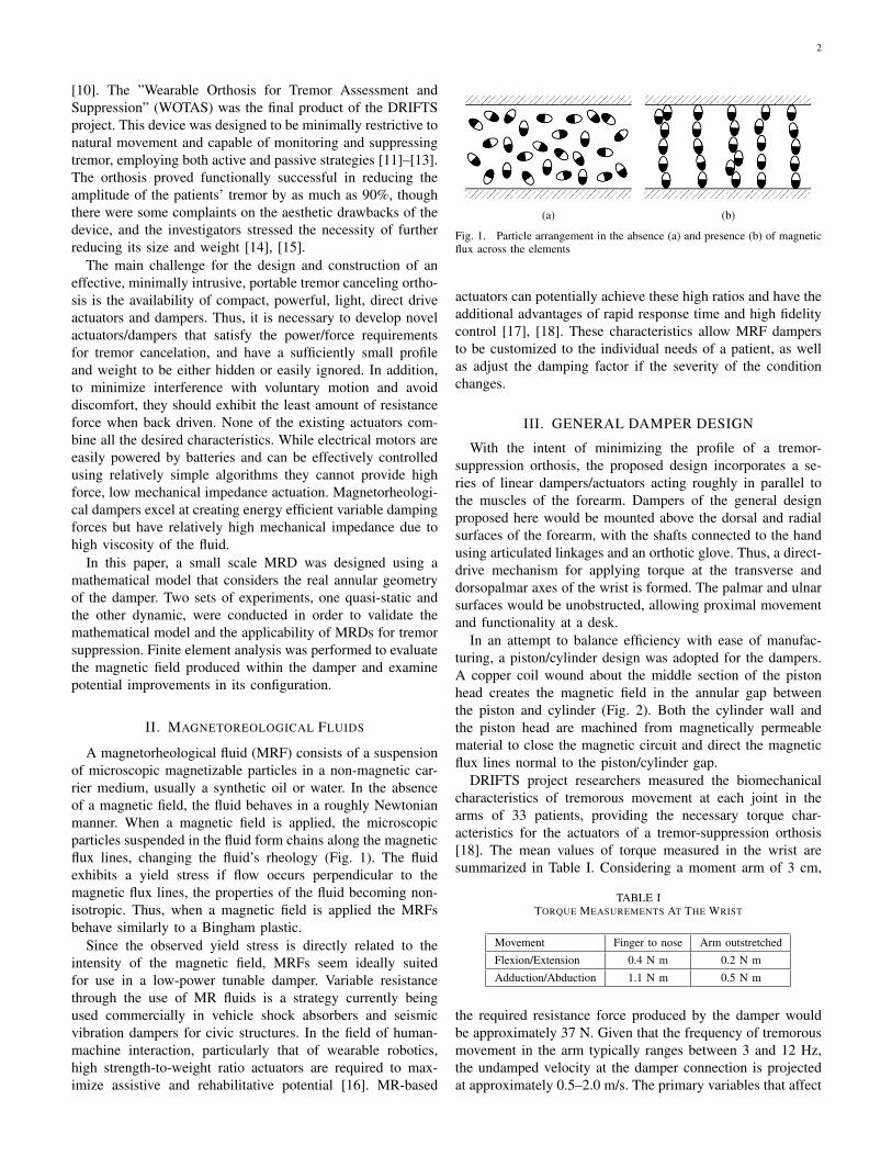
A magnetorheological fluid (MRF) consists of a suspensionof microscopic magnetizable particles in a non-magnetic car-rier medium, usually a synthetic oil or water. In the absenceof a magnetic field, the fluid behaves in a roughly Newtonianmanner. When a magnetic field is applied, the microscopicparticles suspended in the fluid form chains along the magneticflux lines, changing the fluid’s rheology (Fig. 1). The fluidexhibits a yield stress if flow occurs perpendicular to themagnetic flux lines, the properties of the fluid becoming non-isotropic. Thus, when a magnetic field is applied the MRFsbehave similarly to a Bingham plastic.
Since the observed yield stress is directly related to theintensity of the magnetic field, MRFs seem ideally suitedfor use in a low-power tunable damper. Variable resistancethrough the use of MR fluids is a strategy currently beingused commercially in vehicle shock absorbers and seismicvibration dampers for civic structures. In the field of human-machine interaction, particularly that of wearable robotics,high strength-to-weight ratio actuators are required to max-imize assistive and rehabilitative potential [16]. MR-based
(a) (b)
Fig. 1. Particle arrangement in the absence (a) and presence (b) of magneticflux across the elements
actuators can potentially achieve these high ratios and have theadditional advantages of rapid response time and high fidelitycontrol [17], [18]. These characteristics allow MRF dampersto be customized to the individual needs of a patient, as wellas adjust the damping factor if the severity of the conditionchanges.
III. GENERAL DAMPER DESIGN
With the intent of minimizing the profile of a tremor-suppression orthosis, the proposed design incorporates a se-ries of linear dampers/actuators acting roughly in parallel tothe muscles of the forearm. Dampers of the general designproposed here would be mounted above the dorsal and radialsurfaces of the forearm, with the shafts connected to the handusing articulated linkages and an orthotic glove. Thus, a direct-drive mechanism for applying torque at the transverse anddorsopalmar axes of the wrist is formed. The palmar and ulnarsurfaces would be unobstructed, allowing proximal movementand functionality at a desk.
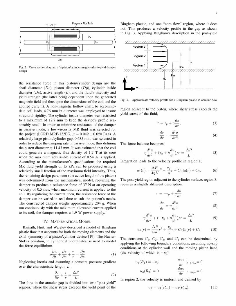
In an attempt to balance efficiency with ease of manufac-turing, a piston/cylinder design was adopted for the dampers.A copper coil wound about the middle section of the pistonhead creates the magnetic field in the annular gap betweenthe piston and cylinder (Fig. 2). Both the cylinder wall andthe piston head are machined from magnetically permeablematerial to close the magnetic circuit and direct the magneticflux lines normal to the piston/cylinder gap.
DRIFTS project researchers measured the biomechanicalcharacteristics of tremorous movement at each joint in thearms of 33 patients, providing the necessary torque char-acteristics for the actuators of a tremor-suppression orthosis[18]. The mean values of torque measured in the wrist aresummarized in Table I. Considering a moment arm of 3 cm,
TABLE ITORQUE MEASUREMENTS AT THE WRIST
Movement Finger to nose Arm outstretched
Flexion/Extension 0.4 N m 0.2 N m
Adduction/Abduction 1.1 N m 0.5 N m
the required resistance force produced by the damper wouldbe approximately 37 N. Given that the frequency of tremorousmovement in the arm typically ranges between 3 and 12 Hz,the undamped velocity at the damper connection is projectedat approximately 0.5–2.0 m/s. The primary variables that affect
3
Fig. 2. Cross section diagram of a piston/cylinder magnetorheological damperdesign
the resistance force in this piston/cylinder design are theshaft diameter (Ds), piston diameter (Dp), cylinder insidediameter (Dc), active length (L), and the fluid’s viscosity andyield strength (the latter being dependent upon the generatedmagnetic field and thus upon the dimensions of the coil and theapplied current). A non-magnetic hollow shaft, to accommo-date coil leads, 4.76 mm in diameter was employed to insurestructural rigidity. The cylinder inside diameter was restrictedto a maximum of 12.7 mm to keep the device’s profile rea-sonably small. In order to minimize resistance of the damperin passive mode, a low-viscosity MR fluid was selected forthe project (LORD MRF-122EG, µ = 0.042± 0.020 Pa.s). Arelatively large piston/cylinder gap, 0.635 mm, was selected inorder to reduce the damping rate in passive mode, thus definingthe piston diameter at 11.43 mm. It was estimated that the coilcould generate a magnetic flux density of 1.7 T at its corewhen the maximum admissible current of 0.54 A is applied.According to the manufacturer’s specifications the requiredMR fluid yield strength of 15 kPa can be produced using arelatively small fraction of the maximum field intensity. Thus,the remaining design parameter (the active length of the piston)was determined from the mathematical model, requiring thedamper to produce a resistance force of 37 N at an operatingvelocity of 0.5 m/s, when maximum current is applied to thecoil. By regulating the current, then, the resistance force of thedamper can be varied in real time to suit the patient’s needs.The constructed damper weighs approximately 204 g. Whenrun continuously with the maximum allowable current appliedto its coil, the damper requires a 1.9 W power supply.
IV. MATHEMATICAL MODEL
Kamath, Hurt, and Wereley described a model of Binghamplastic flow that accounts for both the moving elements and theaxial symmetry of a piston/cylinder device [19]. The Navier-Stokes equation, in cylindrical coordinates, is used to modelthe force equilibrium.
ρ∂u
∂t+∂τ
∂r+τ
r=∂p
∂z(1)
Neglecting inertia and assuming a constant pressure gradientover the characteristic length, L,
∂τ
∂r+τ
r=
∆P
L. (2)
The flow in the annular gap is divided into two “post-yield”regions, where the shear stress exceeds the yield point of the
Bingham plastic, and one “core flow” region, where it doesnot. This produces a velocity profile in the gap as shownin Fig. 3. Applying Bingham’s description in the post-yield
Fig. 3. Approximate velocity profile for a Bingham plastic in annular flow
region adjacent to the piston, where shear stress exceeds theyield stress of the fluid,
τ = τy + ηdu
dr, (3)
dτ
dr= η
d2u
dr2(4)
The force balance becomes
ηd2u
dr2+ (τy + η
du
dr)/r =
∆P
L. (5)
Integration leads to the velocity profile in region 1,
u1(r) =∆P
4ηLr2 − τy
ηr + C1 ln(r) + C2. (6)
The post-yield region adjacent to the cylinder surface, region 3,requires a slightly different description:
τ = −τy + ηdu
dr(7)
dτ
dr= η
d2u
dr2(8)
ηd2u
dr2+ (−τy + η
du
dr)/r =
∆P
L(9)
u3(r) =∆P
4ηLr2 +
τyηr + C3 ln(r) + C4 (10)
The constants C1, C2, C3, and C4 can be determined byapplying the following boundary conditions, assuming no-slipconditions at the cylinder wall and the moving piston head(the velocity of which is −v0):
u1(R1) = −v0du1dr|r→Rpi= 0
u3(R2) = 0du3dr|r→Rpo= 0
In region 2, the velocity is uniform and defined by
u2 = u1(Rpi) = u3(Rpo). (11)
4
A volume balance can thus be established, equating flowthrough the annular gap with fluid displacement due to themotion of the piston profile,
−v0π(R21 −R2
s) =
∫ Rpi
R1
u12πrdr + u2π(R2po −R2
pi) +
+
∫ R2
Rpo
u32πrdr. (12)
The system has effectively three equations with four un-knowns, ∆P , Rpi, Rpo, and u2. To get the final equationnecessary for a solution, the simplified Navier Stokes equationis integrated.
dτ
dr+τ
r=
∆P
L
τ(r) =∆P
2Lr +
C5
r(13)
rτ(r) =∆P
2Lr2 + C5 (14)
The shear stress is known at the limits of the core flow region,allowing the boundary conditions,
τ(Rpi) = τy τ(Rpo) = −τySubstitution leads to the fourth necessary equation:
Rpiτy =∆P
2LR2
pi + C5 (15)
−Rpoτy =∆P
2LR2
po + C5 (16)
(Rpi +Rpo)τy =∆P
2L(R2
pi −R2po) (17)
τy =∆P
2L(Rpi −Rpo) (18)
Thus a complete, nonlinear model for estimation of thesteady-state response of a piston/cylinder type damper withgiven dimensions is obtained.
V. EXPERIMENTAL VALIDATION
A. Quasi-static Response
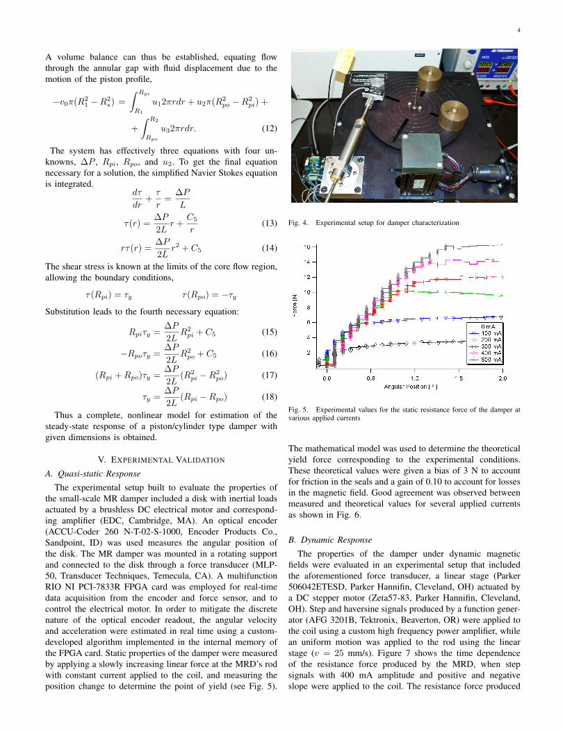
The experimental setup built to evaluate the properties ofthe small-scale MR damper included a disk with inertial loadsactuated by a brushless DC electrical motor and correspond-ing amplifier (EDC, Cambridge, MA). An optical encoder(ACCU-Coder 260 N-T-02-S-1000, Encoder Products Co.,Sandpoint, ID) was used measures the angular position ofthe disk. The MR damper was mounted in a rotating supportand connected to the disk through a force transducer (MLP-50, Transducer Techniques, Temecula, CA). A multifunctionRIO NI PCI-7833R FPGA card was employed for real-timedata acquisition from the encoder and force sensor, and tocontrol the electrical motor. In order to mitigate the discretenature of the optical encoder readout, the angular velocityand acceleration were estimated in real time using a custom-developed algorithm implemented in the internal memory ofthe FPGA card. Static properties of the damper were measuredby applying a slowly increasing linear force at the MRD’s rodwith constant current applied to the coil, and measuring theposition change to determine the point of yield (see Fig. 5).
Fig. 4. Experimental setup for damper characterization
Fig. 5. Experimental values for the static resistance force of the damper atvarious applied currents
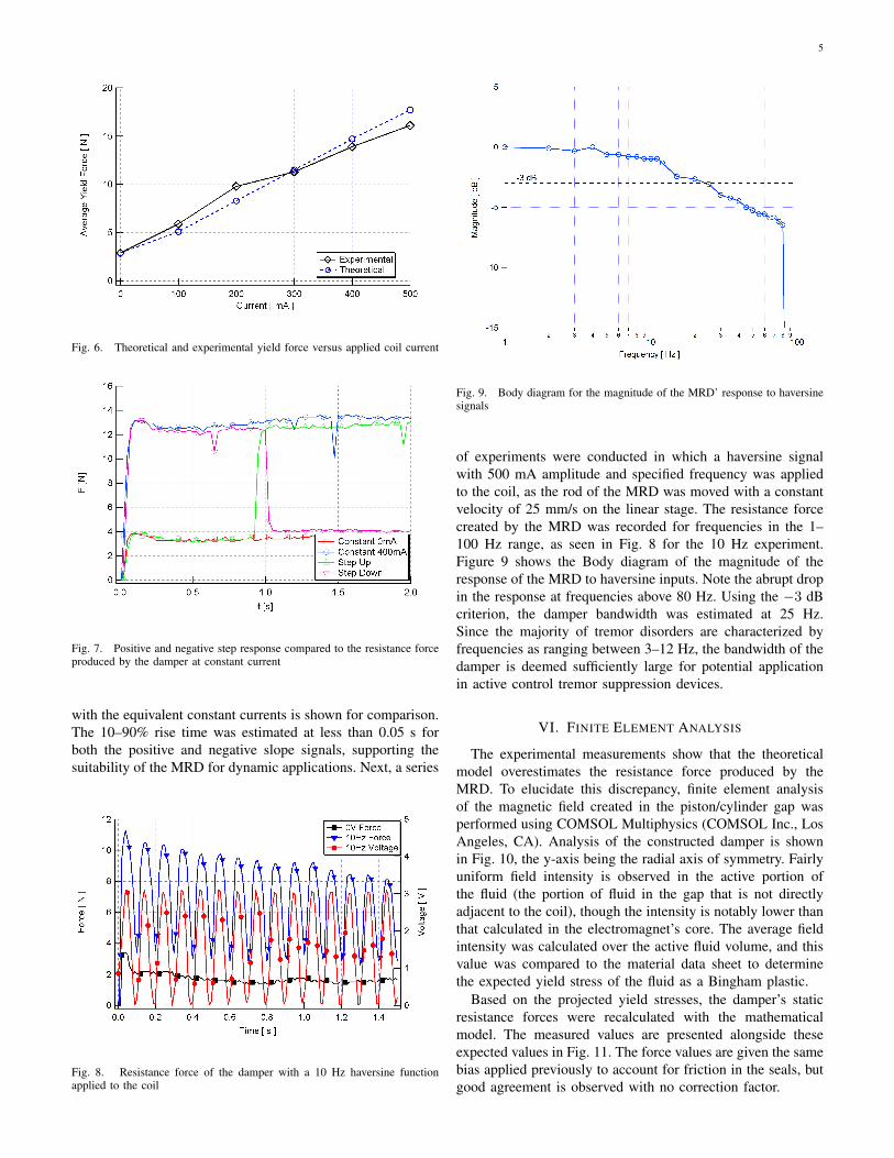
The mathematical model was used to determine the theoreticalyield force corresponding to the experimental conditions.These theoretical values were given a bias of 3 N to accountfor friction in the seals and a gain of 0.10 to account for lossesin the magnetic field. Good agreement was observed betweenmeasured and theoretical values for several applied currentsas shown in Fig. 6.
B. Dynamic Response
The properties of the damper under dynamic magneticfields were evaluated in an experimental setup that includedthe aforementioned force transducer, a linear stage (Parker506042ETESD, Parker Hannifin, Cleveland, OH) actuated bya DC stepper motor (Zeta57-83, Parker Hannifin, Cleveland,OH). Step and haversine signals produced by a function gener-ator (AFG 3201B, Tektronix, Beaverton, OR) were applied tothe coil using a custom high frequency power amplifier, whilean uniform motion was applied to the rod using the linearstage (v = 25 mm/s). Figure 7 shows the time dependenceof the resistance force produced by the MRD, when stepsignals with 400 mA amplitude and positive and negativeslope were applied to the coil. The resistance force produced
5
Fig. 6. Theoretical and experimental yield force versus applied coil current
Fig. 7. Positive and negative step response compared to the resistance forceproduced by the damper at constant current
with the equivalent constant currents is shown for comparison.The 10–90% rise time was estimated at less than 0.05 s forboth the positive and negative slope signals, supporting thesuitability of the MRD for dynamic applications. Next, a series
Fig. 8. Resistance force of the damper with a 10 Hz haversine functionapplied to the coil
Fig. 9. Body diagram for the magnitude of the MRD’ response to haversinesignals
of experiments were conducted in which a haversine signalwith 500 mA amplitude and specified frequency was appliedto the coil, as the rod of the MRD was moved with a constantvelocity of 25 mm/s on the linear stage. The resistance forcecreated by the MRD was recorded for frequencies in the 1–100 Hz range, as seen in Fig. 8 for the 10 Hz experiment.Figure 9 shows the Body diagram of the magnitude of theresponse of the MRD to haversine inputs. Note the abrupt dropin the response at frequencies above 80 Hz. Using the −3 dBcriterion, the damper bandwidth was estimated at 25 Hz.Since the majority of tremor disorders are characterized byfrequencies as ranging between 3–12 Hz, the bandwidth of thedamper is deemed sufficiently large for potential applicationin active control tremor suppression devices.
VI. FINITE ELEMENT ANALYSIS
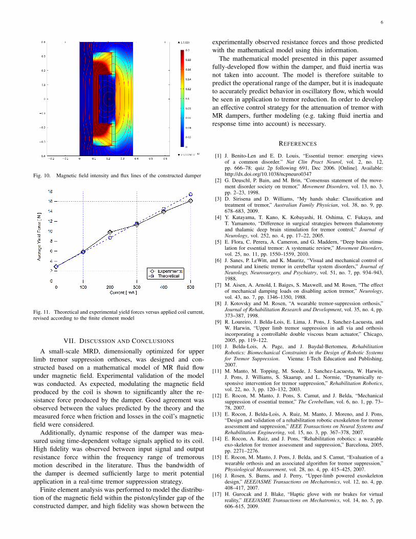
The experimental measurements show that the theoreticalmodel overestimates the resistance force produced by theMRD. To elucidate this discrepancy, finite element analysisof the magnetic field created in the piston/cylinder gap wasperformed using COMSOL Multiphysics (COMSOL Inc., LosAngeles, CA). Analysis of the constructed damper is shownin Fig. 10, the y-axis being the radial axis of symmetry. Fairlyuniform field intensity is observed in the active portion ofthe fluid (the portion of fluid in the gap that is not directlyadjacent to the coil), though the intensity is notably lower thanthat calculated in the electromagnet’s core. The average fieldintensity was calculated over the active fluid volume, and thisvalue was compared to the material data sheet to determinethe expected yield stress of the fluid as a Bingham plastic.
Based on the projected yield stresses, the damper’s staticresistance forces were recalculated with the mathematicalmodel. The measured values are presented alongside theseexpected values in Fig. 11. The force values are given the samebias applied previously to account for friction in the seals, butgood agreement is observed with no correction factor.
6
Fig. 10. Magnetic field intensity and flux lines of the constructed damper
Fig. 11. Theoretical and experimental yield forces versus applied coil current,revised according to the finite element model
VII. DISCUSSION AND CONCLUSIONS
A small-scale MRD, dimensionally optimized for upperlimb tremor suppression orthoses, was designed and con-structed based on a mathematical model of MR fluid flowunder magnetic field. Experimental validation of the modelwas conducted. As expected, modulating the magnetic fieldproduced by the coil is shown to significantly alter the re-sistance force produced by the damper. Good agreement wasobserved between the values predicted by the theory and themeasured force when friction and losses in the coil’s magneticfield were considered.
Additionally, dynamic response of the damper was mea-sured using time-dependent voltage signals applied to its coil.High fidelity was observed between input signal and outputresistance force within the frequency range of tremorousmotion described in the literature. Thus the bandwidth ofthe damper is deemed sufficiently large to merit potentialapplication in a real-time tremor suppression strategy.
Finite element analysis was performed to model the distribu-tion of the magnetic field within the piston/cylinder gap of theconstructed damper, and high fidelity was shown between the
experimentally observed resistance forces and those predictedwith the mathematical model using this information.
The mathematical model presented in this paper assumedfully-developed flow within the damper, and fluid inertia wasnot taken into account. The model is therefore suitable topredict the operational range of the damper, but it is inadequateto accurately predict behavior in oscillatory flow, which wouldbe seen in application to tremor reduction. In order to developan effective control strategy for the attenuation of tremor withMR dampers, further modeling (e.g. taking fluid inertia andresponse time into account) is necessary.
REFERENCES
[1] J. Benito-Len and E. D. Louis, “Essential tremor: emerging viewsof a common disorder.” Nat Clin Pract Neurol, vol. 2, no. 12,pp. 666–78; quiz 2p following 691, Dec 2006. [Online]. Available:http://dx.doi.org/10.1038/ncpneuro0347
[2] G. Deuschl, P. Bain, and M. Brin, “Consensus statement of the move-ment disorder society on tremor,” Movement Disorders, vol. 13, no. 3,pp. 2–23, 1998.
[3] D. Sirisena and D. Williams, “My hands shake: Classification andtreatment of tremor,” Australian Family Physician, vol. 38, no. 9, pp.678–683, 2009.
[4] Y. Katayama, T. Kano, K. Kobayashi, H. Oshima, C. Fukaya, andT. Yamamoto, “Difference in surgical strategies between thalamotomyand thalamic deep brain stimulation for tremor control,” Journal ofNeurology, vol. 252, no. 4, pp. 17–22, 2005.
[5] E. Flora, C. Perera, A. Cameron, and G. Maddern, “Deep brain stimu-lation for essential tremor: A systematic review,” Movement Disorders,vol. 25, no. 11, pp. 1550–1559, 2010.
[6] J. Sanes, P. LeWitt, and K. Mauritz, “Visual and mechanical control ofpostural and kinetic tremor in cerebellar system disorders,” Journal ofNeurology, Neurosurgery, and Psychiatry, vol. 51, no. 7, pp. 934–943,1988.
[7] M. Aisen, A. Arnold, I. Baiges, S. Maxwell, and M. Rosen, “The effectof mechanical damping loads on disabling action tremor,” Neurology,vol. 43, no. 7, pp. 1346–1350, 1988.
[8] J. Kotovsky and M. Rosen, “A wearable tremor-suppression orthosis,”Journal of Rehabilitation Research and Development, vol. 35, no. 4, pp.373–387, 1998.
[9] R. Loureiro, J. Belda-Lois, E. Lima, J. Pons, J. Sanchez-Lacuesta, andW. Harwin, “Upper limb tremor suppression in adl via and orthosisincorporating a controllable double viscous beam actuator,” Chicago,2005, pp. 119–122.
[10] J. Belda-Lois, A. Page, and J. Baydal-Bertomeu, RehabilitationRobotics: Biomechanical Constraints in the Design of Robotic Systemsfor Tremor Suppression. Vienna: I-Tech Education and Publishing,2007.
[11] M. Manto, M. Topping, M. Soede, J. Sanchez-Lacuesta, W. Harwin,J. Pons, J. Williams, S. Skaarup, and L. Normie, “Dynamically re-sponsive intervention for tremor suppression,” Rehabilitation Robotics,vol. 22, no. 3, pp. 120–132, 2003.
[12] E. Rocon, M. Manto, J. Pons, S. Camut, and J. Belda, “Mechanicalsuppression of essential tremor,” The Cerebellum, vol. 6, no. 1, pp. 73–78, 2007.
[13] E. Rocon, J. Belda-Lois, A. Ruiz, M. Manto, J. Moreno, and J. Pons,“Design and validation of a rehabilitation robotic exoskeleton for tremorassessment and suppression,” IEEE Transactions on Neural Systems andRehabilitation Engineering, vol. 15, no. 3, pp. 367–378, 2007.
[14] E. Rocon, A. Ruiz, and J. Pons, “Rehabilitation robotics: a wearableexo-skeleton for tremor assessment and suppression,” Barcelona, 2005,pp. 2271–2276.
[15] E. Rocon, M. Manto, J. Pons, J. Belda, and S. Camut, “Evaluation of awearable orthosis and an associated algorithm for tremor suppression,”Physiological Measurement, vol. 28, no. 4, pp. 415–425, 2007.
[16] J. Rosen, S. Burns, and J. Perry, “Upper-limb powered exoskeletondesign,” IEEE/ASME Transactions on Mechatronics, vol. 12, no. 4, pp.408–417, 2007.
[17] H. Gurocak and J. Blake, “Haptic glove with mr brakes for virtualreality,” IEEE/ASME Transactions on Mechatronics, vol. 14, no. 5, pp.606–615, 2009.

7
[18] M. Kermani and A. Shafer, “On the feasibility and suitability of mr fluidclutches in human-friendly manipulators,” IEEE/ASME Transactions onMechatronics.
[19] G. Kamath, M. Hurt, and N. Wereley, “Analysis and testing of binghamplastic behavior in semi-active electrorheological fluid dampers,” SmartMaterials and Structures, vol. 5, no. 5, pp. 576–590, 1996.