dynamic modeling and optimization of an orc unit … · dynamic modeling and optimization of an orc...
TRANSCRIPT

ScienceDirect
Available online at www.sciencedirect.comAvailable online at www.sciencedirect.com
ScienceDirectEnergy Procedia 00 (2017) 000–000
www.elsevier.com/locate/procedia
1876-6102 © 2017 The Authors. Published by Elsevier Ltd.Peer-review under responsibility of the Scientific Committee of The 15th International Symposium on District Heating and Cooling.
The 15th International Symposium on District Heating and Cooling
Assessing the feasibility of using the heat demand-outdoor temperature function for a long-term district heat demand forecast
I. Andrića,b,c*, A. Pinaa, P. Ferrãoa, J. Fournierb., B. Lacarrièrec, O. Le Correc
aIN+ Center for Innovation, Technology and Policy Research - Instituto Superior Técnico, Av. Rovisco Pais 1, 1049-001 Lisbon, PortugalbVeolia Recherche & Innovation, 291 Avenue Dreyfous Daniel, 78520 Limay, France
cDépartement Systèmes Énergétiques et Environnement - IMT Atlantique, 4 rue Alfred Kastler, 44300 Nantes, France
Abstract
District heating networks are commonly addressed in the literature as one of the most effective solutions for decreasing the greenhouse gas emissions from the building sector. These systems require high investments which are returned through the heatsales. Due to the changed climate conditions and building renovation policies, heat demand in the future could decrease, prolonging the investment return period. The main scope of this paper is to assess the feasibility of using the heat demand – outdoor temperature function for heat demand forecast. The district of Alvalade, located in Lisbon (Portugal), was used as a case study. The district is consisted of 665 buildings that vary in both construction period and typology. Three weather scenarios (low, medium, high) and three district renovation scenarios were developed (shallow, intermediate, deep). To estimate the error, obtained heat demand values were compared with results from a dynamic heat demand model, previously developed and validated by the authors.The results showed that when only weather change is considered, the margin of error could be acceptable for some applications(the error in annual demand was lower than 20% for all weather scenarios considered). However, after introducing renovation scenarios, the error value increased up to 59.5% (depending on the weather and renovation scenarios combination considered). The value of slope coefficient increased on average within the range of 3.8% up to 8% per decade, that corresponds to the decrease in the number of heating hours of 22-139h during the heating season (depending on the combination of weather and renovation scenarios considered). On the other hand, function intercept increased for 7.8-12.7% per decade (depending on the coupled scenarios). The values suggested could be used to modify the function parameters for the scenarios considered, and improve the accuracy of heat demand estimations.
© 2017 The Authors. Published by Elsevier Ltd.Peer-review under responsibility of the Scientific Committee of The 15th International Symposium on District Heating and Cooling.
Keywords: Heat demand; Forecast; Climate change
Energy Procedia 129 (2017) 224–231
1876-6102 © 2017 The Authors. Published by Elsevier Ltd.Peer-review under responsibility of the scientific committee of the IV International Seminar on ORC Power Systems.10.1016/j.egypro.2017.09.146
10.1016/j.egypro.2017.09.146
© 2017 The Authors. Published by Elsevier Ltd.Peer-review under responsibility of the scientific committee of the IV International Seminar on ORC Power Systems.
1876-6102
Available online at www.sciencedirect.com
ScienceDirect Energy Procedia 00 (2017) 000–000
www.elsevier.com/locate/procedia
1876-6102 © 2017 The Authors. Published by Elsevier Ltd.Peer-review under responsibility of the scientific committee of the IV International Seminar on ORC Power Systems.
IV International Seminar on ORC Power Systems, ORC201713-15 September 2017, Milano, Italy
Dynamic modeling and optimization of an ORC unit equipped with plate heat exchangers and turbomachines
Matteo Marchionni, Giuseppe Bianchi*, Apostolos Karvountzis-Kontakiotis,Apostolos Pesiridis and Savvas A. Tassou
Brunel University London, UB8 3PH Uxbridge, United Kingdom
Abstract
Nowadays environmental concerns call for a transition towards an economy based on fossil fuels to a low carbon one. In order to achieve this goal, efficiency optimization of existing energy systems through waste heat to power conversion units based on bottoming Organic Rankine Cycles (ORC) is one of the actions that appears to be suitable and effective both from cost and environmental perspectives. Indeed, these units are able to increase the overall efficiency of production processes, existing facilities and renewable power plants with a limited payback time. However, despite the increasing number of ORC installations at megawatt scale, the waste heat rejected by industrial processes has rather a widespread nature. Hence, ORC units with a power output in the range of kilowatts should be developed to address this opportunity for heat recovery and for business. In the current research activity, a dynamic model of an ORC system was developed in a commercial 1D Computer Aided Engineering software platform. Sub-models of the two plate heat exchangers and of the multi-stage centrifugal pump were developed and calibrated using performance data of industrial components at design and off-design conditions. On the other hand, the R245fa radial turbine design was accomplished using a design procedure that provided geometrical and performance data for the mapping of the device by means of a 1D tool. A steady-state off-design analysis at different operating conditions at the evaporator was further carried out optimizing pump and turbine speeds to maximize the net power output. Furthermore, the thermal inertial effects at the evaporator were assessed with reference to a sample heat load profile of the water hot source and at different time scales.© 2017 The Authors. Published by Elsevier Ltd.Peer-review under responsibility of the scientific committee of the IV International Seminar on ORC Power Systems.
Keywords: Waste heat recovery; Organic Rankine Cycle; Dynamic modelling; Efficiency optimization; turboexpander
* Corresponding author. Tel.: +44-1895-267707; fax: +44-1895-269777.E-mail address: [email protected]

Matteo Marchionni et al. / Energy Procedia 129 (2017) 224–231 225
Available online at www.sciencedirect.com
ScienceDirect Energy Procedia 00 (2017) 000–000
www.elsevier.com/locate/procedia
1876-6102 © 2017 The Authors. Published by Elsevier Ltd.Peer-review under responsibility of the scientific committee of the IV International Seminar on ORC Power Systems.
IV International Seminar on ORC Power Systems, ORC201713-15 September 2017, Milano, Italy
Dynamic modeling and optimization of an ORC unit equipped with plate heat exchangers and turbomachines
Matteo Marchionni, Giuseppe Bianchi*, Apostolos Karvountzis-Kontakiotis,Apostolos Pesiridis and Savvas A. Tassou
Brunel University London, UB8 3PH Uxbridge, United Kingdom
Abstract
Nowadays environmental concerns call for a transition towards an economy based on fossil fuels to a low carbon one. In order to achieve this goal, efficiency optimization of existing energy systems through waste heat to power conversion units based on bottoming Organic Rankine Cycles (ORC) is one of the actions that appears to be suitable and effective both from cost and environmental perspectives. Indeed, these units are able to increase the overall efficiency of production processes, existing facilities and renewable power plants with a limited payback time. However, despite the increasing number of ORC installations at megawatt scale, the waste heat rejected by industrial processes has rather a widespread nature. Hence, ORC units with a power output in the range of kilowatts should be developed to address this opportunity for heat recovery and for business. In the current research activity, a dynamic model of an ORC system was developed in a commercial 1D Computer Aided Engineering software platform. Sub-models of the two plate heat exchangers and of the multi-stage centrifugal pump were developed and calibrated using performance data of industrial components at design and off-design conditions. On the other hand, the R245fa radial turbine design was accomplished using a design procedure that provided geometrical and performance data for the mapping of the device by means of a 1D tool. A steady-state off-design analysis at different operating conditions at the evaporator was further carried out optimizing pump and turbine speeds to maximize the net power output. Furthermore, the thermal inertial effects at the evaporator were assessed with reference to a sample heat load profile of the water hot source and at different time scales.© 2017 The Authors. Published by Elsevier Ltd.Peer-review under responsibility of the scientific committee of the IV International Seminar on ORC Power Systems.
Keywords: Waste heat recovery; Organic Rankine Cycle; Dynamic modelling; Efficiency optimization; turboexpander
* Corresponding author. Tel.: +44-1895-267707; fax: +44-1895-269777.E-mail address: [email protected]
2 Matteo Marchionni et al./ Energy Procedia 00 (2017) 000–000
1. Introduction
The growing energy demand in the world, the scarcity of natural resources and the increasing environmental concerns due to the excessive pollutant emissions led governments, national and international organization to more sustainable and eco-friendly energetic and industrial policies. As a consequence, many research activities have been carried out in order to investigate reliable solutions capable to effectively exploit renewable energy sources and to improve the overall efficiency of existing power generation and industrial facilities.
Among these, since the heat rejected by industrial processes is still a remarkable share of the world energy consumption, waste heat to power conversion systems represent one of the most promising and effective ways to contribute to the achievement of these targets. In particular, the organic Rankine cycle (ORC) technology has proven to be reliable, cost-effective and easy to maintain [1] both for low grade and ultra-low grade waste heat recovery applications [2, 3]. For large scale heat sources between few hundreds of kWth up to few MWth, an ORC power systemis a mature and economic-optimized technology to convert heat into electricity from geothermal reservoirs [4-7],concentrated solar power plants [8, 9] and in biomass combined heat and power installations [10].
However, considering smaller units, whose thermal power input range is between few kilowatts to 100 kW, there are aspects which have not been fully addressed yet and the research is still undergoing. Among them, one of the most relevant topics is undoubtedly the accurate modeling of the system dynamics, especially of the heat exchangers and the expander side, for design, optimization and control purposes [11]. In fact, in applications as the automotive ones, ORC systems are asked to be flexible and reliable for several working conditions, since the heat load supplied to the system can change rapidly in a periodic or random way, as it occurs in engine ORC systems under transient driving cycle conditions. For these reasons, the proper modeling and analysis of transients, is strongly needed, also to allow the optimization of the power plant in several operating points.
Among the research works that have been carried out in this area, in [12] a dynamic model of a small scale ORC power plant for WHR applications using a scroll expander as power conversion unit has been proposed. The aim of the work was the validation of a control strategy able to optimize the system overall efficiency varying the heat load supplied. In [13] a 150 kWel ORC system using an innovative turbogenerator has been presented with the same purpose. In [14, 15] the effects of the introduction of an 11 kWel screw expander in a ORC system have been analyzed, while in [16, 17] the authors presented the dynamic model of the same system and designed a control strategy acting on the pump frequency in order to regulate the working fluid superheating. In [18, 19], a dynamic model able to predict the behavior of a few MWel scale ORC WHR systems has been proposed, with the aim of reproducing and analyzingits performance and behavior at off-design conditions without having the control actions affecting the system dynamics. The tools used in these aforementioned studies were Modelica and Matlab/Simulink.
Although these simulation platforms allow to model and analyze all the ORC components, they also require an extensive effort and time to implement customized or mere literature models that are not anymore innovative.Therefore, when the goal is to look into the interactions between conventional components, commercial software platforms become equally attractive and timewise effective. For these reasons, in this work a modeling methodology to predict the steady-state and transient behavior of a small scale ORC system is proposed. The approach adopted permits to consistently reduce the model implementation time and it has the additional benefit to be highly replicableboth in research and in industry. The approach refers to a radial turbine, which presents several advantages as compactness, economic convenience and ease of maintenance. Besides the modeling methodology and implementation, this study shows the ORC performance at off-design conditions due to different hot source mass flow rates and temperatures and achieved through an optimization of turbine and pump speeds. The transient response of the water-R245fa plate heat exchanger evaporator and the effects on the turbine inlet temperature have been eventually assessed with reference to a series of heat loads at different time scales.
2. System description
The model presented in this work describes an ORC power plant for stationary waste heat recovery applications. With reference to the modeling scheme in Figure 1, the heat recovery takes place through a plate heat exchanger having water on the hot side and the working fluid of the system, which is R245fa, on the cold side. After being pressurized in a multi-stage centrifugal pump, the working fluid undergoes to a full vaporization during the heat
226 Matteo Marchionni et al. / Energy Procedia 129 (2017) 224–231Matteo Marchionni et al./ Energy Procedia 00 (2017) 000–000 3
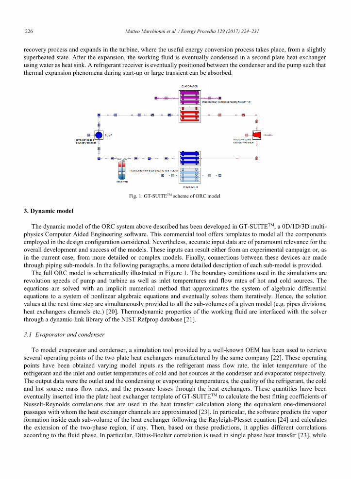
recovery process and expands in the turbine, where the useful energy conversion process takes place, from a slightly superheated state. After the expansion, the working fluid is eventually condensed in a second plate heat exchanger using water as heat sink. A refrigerant receiver is eventually positioned between the condenser and the pump such that thermal expansion phenomena during start-up or large transient can be absorbed.
Fig. 1. GT-SUITETM scheme of ORC model
3. Dynamic model
The dynamic model of the ORC system above described has been developed in GT-SUITETM, a 0D/1D/3D multi-physics Computer Aided Engineering software. This commercial tool offers templates to model all the components employed in the design configuration considered. Nevertheless, accurate input data are of paramount relevance for the overall development and success of the models. These inputs can result either from an experimental campaign or, as in the current case, from more detailed or complex models. Finally, connections between these devices are made through piping sub-models. In the following paragraphs, a more detailed description of each sub-model is provided.
The full ORC model is schematically illustrated in Figure 1. The boundary conditions used in the simulations are revolution speeds of pump and turbine as well as inlet temperatures and flow rates of hot and cold sources. The equations are solved with an implicit numerical method that approximates the system of algebraic differential equations to a system of nonlinear algebraic equations and eventually solves them iteratively. Hence, the solution values at the next time step are simultaneously provided to all the sub-volumes of a given model (e.g. pipes divisions, heat exchangers channels etc.) [20]. Thermodynamic properties of the working fluid are interfaced with the solver through a dynamic-link library of the NIST Refprop database [21].
3.1 Evaporator and condenser
To model evaporator and condenser, a simulation tool provided by a well-known OEM has been used to retrieveseveral operating points of the two plate heat exchangers manufactured by the same company [22]. These operating points have been obtained varying model inputs as the refrigerant mass flow rate, the inlet temperature of the refrigerant and the inlet and outlet temperatures of cold and hot sources at the condenser and evaporator respectively.The output data were the outlet and the condensing or evaporating temperatures, the quality of the refrigerant, the cold and hot source mass flow rates, and the pressure losses through the heat exchangers. These quantities have beeneventually inserted into the plate heat exchanger template of GT-SUITETM to calculate the best fitting coefficients of Nusselt-Reynolds correlations that are used in the heat transfer calculation along the equivalent one-dimensional passages with whom the heat exchanger channels are approximated [23]. In particular, the software predicts the vapor formation inside each sub-volume of the heat exchanger following the Rayleigh-Plesset equation [24] and calculates the extension of the two-phase region, if any. Then, based on these predictions, it applies different correlations according to the fluid phase. In particular, Dittus-Boelter correlation is used in single phase heat transfer [23], while

Matteo Marchionni et al. / Energy Procedia 129 (2017) 224–231 227Matteo Marchionni et al./ Energy Procedia 00 (2017) 000–000 3
recovery process and expands in the turbine, where the useful energy conversion process takes place, from a slightly superheated state. After the expansion, the working fluid is eventually condensed in a second plate heat exchanger using water as heat sink. A refrigerant receiver is eventually positioned between the condenser and the pump such that thermal expansion phenomena during start-up or large transient can be absorbed.
Fig. 1. GT-SUITETM scheme of ORC model
3. Dynamic model
The dynamic model of the ORC system above described has been developed in GT-SUITETM, a 0D/1D/3D multi-physics Computer Aided Engineering software. This commercial tool offers templates to model all the components employed in the design configuration considered. Nevertheless, accurate input data are of paramount relevance for the overall development and success of the models. These inputs can result either from an experimental campaign or, as in the current case, from more detailed or complex models. Finally, connections between these devices are made through piping sub-models. In the following paragraphs, a more detailed description of each sub-model is provided.
The full ORC model is schematically illustrated in Figure 1. The boundary conditions used in the simulations are revolution speeds of pump and turbine as well as inlet temperatures and flow rates of hot and cold sources. The equations are solved with an implicit numerical method that approximates the system of algebraic differential equations to a system of nonlinear algebraic equations and eventually solves them iteratively. Hence, the solution values at the next time step are simultaneously provided to all the sub-volumes of a given model (e.g. pipes divisions, heat exchangers channels etc.) [20]. Thermodynamic properties of the working fluid are interfaced with the solver through a dynamic-link library of the NIST Refprop database [21].
3.1 Evaporator and condenser
To model evaporator and condenser, a simulation tool provided by a well-known OEM has been used to retrieveseveral operating points of the two plate heat exchangers manufactured by the same company [22]. These operating points have been obtained varying model inputs as the refrigerant mass flow rate, the inlet temperature of the refrigerant and the inlet and outlet temperatures of cold and hot sources at the condenser and evaporator respectively.The output data were the outlet and the condensing or evaporating temperatures, the quality of the refrigerant, the cold and hot source mass flow rates, and the pressure losses through the heat exchangers. These quantities have beeneventually inserted into the plate heat exchanger template of GT-SUITETM to calculate the best fitting coefficients of Nusselt-Reynolds correlations that are used in the heat transfer calculation along the equivalent one-dimensional passages with whom the heat exchanger channels are approximated [23]. In particular, the software predicts the vapor formation inside each sub-volume of the heat exchanger following the Rayleigh-Plesset equation [24] and calculates the extension of the two-phase region, if any. Then, based on these predictions, it applies different correlations according to the fluid phase. In particular, Dittus-Boelter correlation is used in single phase heat transfer [23], while
4 Matteo Marchionni et al./ Energy Procedia 00 (2017) 000–000
in the two-phase region, the correlation from Yao et al. has been considered for the condenser [25] and the one from Donowsky and Kandlikar for the evaporator [26].
The heat exchangers’ inertia, affected by the metallic mass and the capacity of the device, is eventually taken in account by giving in input to the software the geometrical data and the heat exchanger material.
3.2 Pump
The pump has been modeled by calculating its performance and isentropic efficiency map by means of a regression analysis based on a set of real operating points (pressure rise, volumetric flow rate and power consumption) available on the website of the manufacturer. Regarding the performance map, since the real data were available only for acertain range of revolution speeds, in particular between 1800 and 3000 RPM, the performance curves for speeds lower than 1800 RPM have been computed using a linear extrapolation method. The isentropic efficiency map instead, has been calculated based on the interpolated power consumption data. Figure 2 reports performance and isentropic efficiency maps of the pump.
Fig. 2: Pump performance (a) and efficiency (b) maps
3.3 Radial Turbine
The radial turbine has been modeled following the approach developed and described in [27]. The model considers the rotor, the stator and the volute of the turbine, assumed for simplicity as a circular cross section, in order to accurately estimate the fluid dynamic losses. To start the procedure, first, a set of geometrical and thermodynamics parameters are required [28-31], chosen respectively by manufacturability considerations and according to the design operating point of the ORC power plant object of this work. Given these input data, an isentropic efficiency at the design operating point of the expander is estimated, then the enthalpy drops in the rotor, stator and in the volute are computed. Consequently, a new isentropic efficiency value is calculated and compared with the previous estimated one. The procedure is thus repeated until a convergence is reached. The above expander design loop has been coupled with the MATLABTM optimization toolbox in order to optimize the inlet parameters, using as objective function the isentropic efficiency of the expander.
After this design stage, the commercial 0D/1D commercial software RITALTM has been used to calculate the turbine performance and isentropic efficiency map, in order to have a model able to describe accurately the expander behavior under off-design conditions. Firstly RITAL was calibrated in order to predict the expander design conditions. Then it was used to calculate the off-design performance of the expander. Last but not least, these operating maps obtained with the aforementioned approach have been implemented in GT-SUITETM and are reported in Figure 3.
3.4 Piping and receiver
Straight pipes have been considered as one dimensional ducts with a circular cross section and with a roughness value typical for stainless steel. Additional bends have been modeled using the software library that already contains
600
900
1200
1500
1500
1800
1800
2100
2100
2100
2400
2400
2400
2700
2700
2700
(a) revolution speed [RPM]
flow rate [m 3 /s] 10 -3
0 0.5 1 1.5 2 2.5 3 3.5 4 4.5
pres
sure
rise
[bar
]
0
5
10
15
20
1515
15
15
22.5
22.5
22.5
22.5
30
30
30 3037
.5
37.5
37.5
37.5
45
45
45
52.5
52.5
52.5
60
60
67.5
67.5
(b) isentropic efficiency [%]
flow rate [m 3 /s] 10 -3
0 0.5 1 1.5 2 2.5 3 3.5 4 4.5
pres
sure
rise
[bar
]
0
5
10
15
20

228 Matteo Marchionni et al. / Energy Procedia 129 (2017) 224–231Matteo Marchionni et al./ Energy Procedia 00 (2017) 000–000 5
the localized pressure drops due to such components. For sake of simplicity, assuming that the pipes are insulated, adiabatic conditions were set to prevent any heat loss to the environment. The receiver size was chosen to be the 25% of the system capacity as suggested in the software guidelines [20].
Fig. 3. Non dimensional turbine performance (a) and total-static efficiency (b) maps
4. Results and discussion
4.1. Off-design performance
After the modeling stage, a series of simulations were carried out in GT-SUITETM to characterize the steady-state performance of the ORC system varying the heat load supplied by the stream rejected by the topping facility. Since the heat load of this stream is completely defined by its mass flow rate and inlet temperature, these conditions werechanged during the simulations with respect to the design point at 10 kg/s and 110°C. On the other hand, the thermodynamic conditions of the heat sink remained unchanged to the design values of 14.3 kg/s and 35°C.
For each case, the net power output was maximized with respect to pump and turbine speeds as independent variables. The optimization algorithm that was employed is the Nelder Mead SIMPLEX one, which is suitable for finding a local minimum and at a low computational cost since no derivative calculations are involved. For two independent variables as in the current case, the method is a pattern search that compares function values at the three vertices of a triangle. The worst vertex, is rejected and replaced with a new vertex. A new triangle is formed and the search is continued. The process generates a sequence of triangles for which the values of the optimization function at the vertices get smaller and smaller. The size of the triangles is reduced and the coordinates of the minimum point are found. Furthermore, this algorithm allows to perform also constrained optimizations by penalizing the regions which violate the constraints imposed [32, 20]. In this case the constraint was the fulfilment of at least saturated conditions at the turbine inlet.
The results of the analysis are reported in Figure 4. In particular, Figure 4.a shows the vapor quality of the working fluid at the inlet of the turbine and, in turn, the operating range of the system. In fact, a durable and reliable usage of turboexpander requires the inlet conditions of the working fluid to be slightly superheated. To face this well-known issue, a future control strategy to be implemented in this ORC unit will need to shut down the system when the waste heat temperature is below 100°C or 110°C for mass flow rates lower than 7.2 kg/s. Alternatively, the turbine could be by-passed using an additional branch in parallel with the expander and where an expansion valve will simulate the pressure drop due to the turbine. This isenthalpic transformation might however require an oversizing of the condenser.Figure 4.b shows the maximized net power output in the operating range identified by the quality constraint. This quantity ranges from 34.5 kW to 55.5 kW and increases with both hot source inlet temperature and mass flow rate. In particular, for a given hot source temperature, beyond a given threshold (e.g. 9 kg/s) the inlet quality at the turbine (e.g. 1.05) is not affected by the increase of hot source mass flow rate. Therefore, the increase in power output is not due to a greater specific work but rather to a greater working fluid mass flow rate that balances the heat load at the

Matteo Marchionni et al. / Energy Procedia 129 (2017) 224–231 229Matteo Marchionni et al./ Energy Procedia 00 (2017) 000–000 5
the localized pressure drops due to such components. For sake of simplicity, assuming that the pipes are insulated, adiabatic conditions were set to prevent any heat loss to the environment. The receiver size was chosen to be the 25% of the system capacity as suggested in the software guidelines [20].
Fig. 3. Non dimensional turbine performance (a) and total-static efficiency (b) maps
4. Results and discussion
4.1. Off-design performance
After the modeling stage, a series of simulations were carried out in GT-SUITETM to characterize the steady-state performance of the ORC system varying the heat load supplied by the stream rejected by the topping facility. Since the heat load of this stream is completely defined by its mass flow rate and inlet temperature, these conditions werechanged during the simulations with respect to the design point at 10 kg/s and 110°C. On the other hand, the thermodynamic conditions of the heat sink remained unchanged to the design values of 14.3 kg/s and 35°C.
For each case, the net power output was maximized with respect to pump and turbine speeds as independent variables. The optimization algorithm that was employed is the Nelder Mead SIMPLEX one, which is suitable for finding a local minimum and at a low computational cost since no derivative calculations are involved. For two independent variables as in the current case, the method is a pattern search that compares function values at the three vertices of a triangle. The worst vertex, is rejected and replaced with a new vertex. A new triangle is formed and the search is continued. The process generates a sequence of triangles for which the values of the optimization function at the vertices get smaller and smaller. The size of the triangles is reduced and the coordinates of the minimum point are found. Furthermore, this algorithm allows to perform also constrained optimizations by penalizing the regions which violate the constraints imposed [32, 20]. In this case the constraint was the fulfilment of at least saturated conditions at the turbine inlet.
The results of the analysis are reported in Figure 4. In particular, Figure 4.a shows the vapor quality of the working fluid at the inlet of the turbine and, in turn, the operating range of the system. In fact, a durable and reliable usage of turboexpander requires the inlet conditions of the working fluid to be slightly superheated. To face this well-known issue, a future control strategy to be implemented in this ORC unit will need to shut down the system when the waste heat temperature is below 100°C or 110°C for mass flow rates lower than 7.2 kg/s. Alternatively, the turbine could be by-passed using an additional branch in parallel with the expander and where an expansion valve will simulate the pressure drop due to the turbine. This isenthalpic transformation might however require an oversizing of the condenser.Figure 4.b shows the maximized net power output in the operating range identified by the quality constraint. This quantity ranges from 34.5 kW to 55.5 kW and increases with both hot source inlet temperature and mass flow rate. In particular, for a given hot source temperature, beyond a given threshold (e.g. 9 kg/s) the inlet quality at the turbine (e.g. 1.05) is not affected by the increase of hot source mass flow rate. Therefore, the increase in power output is not due to a greater specific work but rather to a greater working fluid mass flow rate that balances the heat load at the
6 Matteo Marchionni et al./ Energy Procedia 00 (2017) 000–000
evaporator and that is due to higher revolution speeds of the turbomachines. Below that threshold, a lower hot source mass flow rate leads to a lower inlet quality and working fluid mass flow rate that both contribute to decrease the net power output. However, these considerations are fluid dependent and may highly differ in other design configurations (e.g. with gaseous heat sources.)
Fig. 4. ORC system performance at off-design conditions with optimized pump and turbine speeds:effects on turbine inlet quality (at least equal to 1) (a) and net power output (b)
4.2. Transient thermal input
In the simplest architecture, such as the one investigated in the current study, an ORC system is at least composed of two heat exchangers and one receiver. These components are not only filled with large quantities of working fluid but also have metallic surfaces whose thicknesses need to withstand high pressures. The thermal inertia due to these coexisting effects acts as a low pass filter for the ORC system and needs to be taken into account when developing a control system for an ORC unit, especially if the final application is a transportation one.
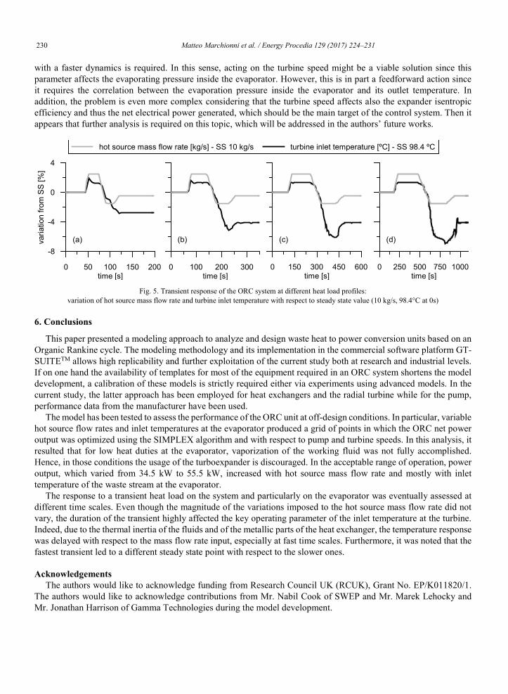
In order to stress and demonstrate this concept, transient simulations were carried out on the modeled ORC system. In particular, the simulations imposed a variable mass flow rate at the hot side of the evaporator and observed the effects on a fundamental parameter of the ORC operation, namely the turbine inlet temperature. Figure 5 summarizes the transient analysis with respect to a steady state value marked with SS. The grey line refers to the input while the black one to the output. The mass flow rate profile is composed of two ramps and two plateaus. Durations of the transient inputs are 200, 350, 600 and 1100s. Other operating parameters in the ORC system were not varied, neither optimized.
Figure 5.a shows that the response to the transient input is delayed and it is not able to follow the load variation. In fact, the intermediate plateaus are not reproduced in the temperature trace. In turn, the overall effect on the turbine inlet temperature is a variation of 2.7K. In Figure 5.b the duration of the transient and of the single phases was nearly doubled compared to the previous one. In turn, although the temperature overshooting after the first ramp is still noticeable and delayed, the temperature trend starts to resemble the mass flow rate profile. Moreover, the second plateau is still not well resolved and the overall temperature decrease from the initial value is 4.1K. This new steady state is reproduced in the cases shown in Figures 5.c and 5.d that are further characterized by a confident reproduction of the mass flow rate input.
In a control perspective, these results suggest the adoption of different control strategies for variable heat loads atdifferent time scales. For instance, when the hot source presents slow variations in time, as in Figure 5.c, 5.d and typically in stationary applications, the time constants of the heat exchanger and the one of the variation are comparable. In turn, the temperature of the working fluid at the turbine inlet could be set acting on the mass flow rates of the evaporator. Instead, when more rapid changes of the heat load are considered, as in Figure 5.a and 5.b and generally in automotive applications, then an action on the mass flows can result trivial, and the regulation of a variable
230 Matteo Marchionni et al. / Energy Procedia 129 (2017) 224–231Matteo Marchionni et al./ Energy Procedia 00 (2017) 000–000 7
with a faster dynamics is required. In this sense, acting on the turbine speed might be a viable solution since this parameter affects the evaporating pressure inside the evaporator. However, this is in part a feedforward action since it requires the correlation between the evaporation pressure inside the evaporator and its outlet temperature. In addition, the problem is even more complex considering that the turbine speed affects also the expander isentropic efficiency and thus the net electrical power generated, which should be the main target of the control system. Then it appears that further analysis is required on this topic, which will be addressed in the authors’ future works.
Fig. 5. Transient response of the ORC system at different heat load profiles:variation of hot source mass flow rate and turbine inlet temperature with respect to steady state value (10 kg/s, 98.4°C at 0s)
6. Conclusions
This paper presented a modeling approach to analyze and design waste heat to power conversion units based on an Organic Rankine cycle. The modeling methodology and its implementation in the commercial software platform GT-SUITETM allows high replicability and further exploitation of the current study both at research and industrial levels. If on one hand the availability of templates for most of the equipment required in an ORC system shortens the model development, a calibration of these models is strictly required either via experiments using advanced models. In the current study, the latter approach has been employed for heat exchangers and the radial turbine while for the pump, performance data from the manufacturer have been used.
The model has been tested to assess the performance of the ORC unit at off-design conditions. In particular, variable hot source flow rates and inlet temperatures at the evaporator produced a grid of points in which the ORC net power output was optimized using the SIMPLEX algorithm and with respect to pump and turbine speeds. In this analysis, it resulted that for low heat duties at the evaporator, vaporization of the working fluid was not fully accomplished. Hence, in those conditions the usage of the turboexpander is discouraged. In the acceptable range of operation, power output, which varied from 34.5 kW to 55.5 kW, increased with hot source mass flow rate and mostly with inlet temperature of the waste stream at the evaporator.
The response to a transient heat load on the system and particularly on the evaporator was eventually assessed at different time scales. Even though the magnitude of the variations imposed to the hot source mass flow rate did not vary, the duration of the transient highly affected the key operating parameter of the inlet temperature at the turbine. Indeed, due to the thermal inertia of the fluids and of the metallic parts of the heat exchanger, the temperature response was delayed with respect to the mass flow rate input, especially at fast time scales. Furthermore, it was noted that the fastest transient led to a different steady state point with respect to the slower ones.
AcknowledgementsThe authors would like to acknowledge funding from Research Council UK (RCUK), Grant No. EP/K011820/1.
The authors would like to acknowledge contributions from Mr. Nabil Cook of SWEP and Mr. Marek Lehocky and Mr. Jonathan Harrison of Gamma Technologies during the model development.
0 250 500 750 1000time [s]
0 150 300 450 600time [s]
0 100 200 300time [s]
0 50 100 150 200time [s]
-8
-4
0
4
varia
tion
from
SS
[%]
hot source mass flow rate [kg/s] - SS 10 kg/s turbine inlet temperature [ºC] - SS 98.4 ºC
(a) (b) (c) (d)
Matteo Marchionni et al. / Energy Procedia 129 (2017) 224–231 231Matteo Marchionni et al./ Energy Procedia 00 (2017) 000–000 7
with a faster dynamics is required. In this sense, acting on the turbine speed might be a viable solution since this parameter affects the evaporating pressure inside the evaporator. However, this is in part a feedforward action since it requires the correlation between the evaporation pressure inside the evaporator and its outlet temperature. In addition, the problem is even more complex considering that the turbine speed affects also the expander isentropic efficiency and thus the net electrical power generated, which should be the main target of the control system. Then it appears that further analysis is required on this topic, which will be addressed in the authors’ future works.
Fig. 5. Transient response of the ORC system at different heat load profiles:variation of hot source mass flow rate and turbine inlet temperature with respect to steady state value (10 kg/s, 98.4°C at 0s)
6. Conclusions
This paper presented a modeling approach to analyze and design waste heat to power conversion units based on an Organic Rankine cycle. The modeling methodology and its implementation in the commercial software platform GT-SUITETM allows high replicability and further exploitation of the current study both at research and industrial levels. If on one hand the availability of templates for most of the equipment required in an ORC system shortens the model development, a calibration of these models is strictly required either via experiments using advanced models. In the current study, the latter approach has been employed for heat exchangers and the radial turbine while for the pump, performance data from the manufacturer have been used.
The model has been tested to assess the performance of the ORC unit at off-design conditions. In particular, variable hot source flow rates and inlet temperatures at the evaporator produced a grid of points in which the ORC net power output was optimized using the SIMPLEX algorithm and with respect to pump and turbine speeds. In this analysis, it resulted that for low heat duties at the evaporator, vaporization of the working fluid was not fully accomplished. Hence, in those conditions the usage of the turboexpander is discouraged. In the acceptable range of operation, power output, which varied from 34.5 kW to 55.5 kW, increased with hot source mass flow rate and mostly with inlet temperature of the waste stream at the evaporator.
The response to a transient heat load on the system and particularly on the evaporator was eventually assessed at different time scales. Even though the magnitude of the variations imposed to the hot source mass flow rate did not vary, the duration of the transient highly affected the key operating parameter of the inlet temperature at the turbine. Indeed, due to the thermal inertia of the fluids and of the metallic parts of the heat exchanger, the temperature response was delayed with respect to the mass flow rate input, especially at fast time scales. Furthermore, it was noted that the fastest transient led to a different steady state point with respect to the slower ones.
AcknowledgementsThe authors would like to acknowledge funding from Research Council UK (RCUK), Grant No. EP/K011820/1.
The authors would like to acknowledge contributions from Mr. Nabil Cook of SWEP and Mr. Marek Lehocky and Mr. Jonathan Harrison of Gamma Technologies during the model development.
0 250 500 750 1000time [s]
0 150 300 450 600time [s]
0 100 200 300time [s]
0 50 100 150 200time [s]
-8
-4
0
4
varia
tion
from
SS
[%]
hot source mass flow rate [kg/s] - SS 10 kg/s turbine inlet temperature [ºC] - SS 98.4 ºC
(a) (b) (c) (d)
8 Matteo Marchionni et al./ Energy Procedia 00 (2017) 000–000
References[1] G. Angelino, M. Gaia, and E. Macchi, “Review of Italian activity in the field of Organic Rankine Cycles” in VDI Berichte, 1984, pp. 465–482.[2] A. Verneau, “Waste heat recovery by organic fluid rankine cycle,” 1979.[3] C. Carcasci, R. Ferraro, and E. Miliotti, “Thermodynamic analysis of an organic Rankine cycle for waste heat recovery from gas turbines,” Energy, 2014.[4] Alle, “One MW binary cycle turbogenerator module made in Europe,” Proc. of the World Geothermal Congress, vol. 3. pp. 2125–2130, 1995.[5] U. Kaplan, “Advanced Organic Rankine Cycles in binary geothermal power plants” Ormat Technologies Inc., 2007. URL: www.ormat.com/research/papers/papers3.[6] M. Astolfi, M. C. Romano, P. Bombarda, and E. Macchi, “Binary ORC (Organic Rankine Cycles) power plants for the exploitation of medium-low temperature geothermal sources - Part B: Techno-economic optimization,” Energy, vol. 66, pp. 435–446, 2014.[7] A. Franco, “Power production from a moderate temperature geothermal resource with regenerative Organic Rankine Cycles,” Energy Sustain. Dev., vol. 15, no. 4, pp. 411–419, 2011.[8] S. Canada, D. A. Brosseau, and H. Price, “Design and construction of the APS 1-MWE parabolic trough power plant,” in American Solar Energy Society - Solar 2006: 35th ASES Annual Conf., 31st ASES National Passive Solar Conf., 1st ASES Policy and Marketing Conf., ASME Solar Energy Division Int. Solar Energy Conference, 2006, vol. 2, pp. 1056–1063.[9] S. Quoilin, M. Van Den Broek, S. Declaye, P. Dewallef, and V. Lemort, “Techno-economic survey of organic rankine cycle (ORC) systems,” Renewable and Sustainable Energy Reviews, vol. 22. pp. 168–186, 2013.[10] I. Obernberger, P. Thonhofer, and E. Reisenhofer, “Description and evaluation of the new 1000 kWel Organic Rankine Cycle process integrated in the biomass CHP plant in Lienz, Austria,” Euroheat & Power, 2002.[11] D. Wei, X. Lu, Z. Lu, and J. Gu, “Dynamic modeling and simulation of an Organic Rankine Cycle (ORC) system for waste heat recovery,” Appl. Therm. Eng., vol. 28, no. 10, pp. 1216–1224, 2008.[12] S. Quoilin, R. Aumann, A. Grill, A. Schuster, V. Lemort, and H. Spliethoff, “Dynamic modeling and optimal control strategy of waste heat recovery Organic Rankine Cycles,” Appl. Energy, vol. 88, no. 6, pp. 2183–2190, 2011.[13] F. Casella and T. Mathijssen, “Dynamic modeling of organic rankine cycle power systems,” J., 2013.[14] D. Ziviani, A. Beyene, and M. Venturini, “Development and Validation of an Advanced Simulation Model for ORC-Based Systems,” ASME 2012, 2012.[15] D. Ziviani, A. Beyene, and M. Venturini, “Advances and challenges in ORC systems modeling for low grade thermal energy recovery,” Appl. Energy, 2014.[16] D. Ziviani, M. van den Broek, and M. De Paepe, “Geometry-based modeling of single screw expander for organic rankine cycle systems in low-grade heat recovery,” Energy Procedia, 2014.[17] A. Desideri, A. Hernandez, S. Gusev, M. van den Broek, V. Lemort, and S. Quoilin, “Steady-state and dynamic validation of a small-scale waste heat recovery system using the ThermoCycle Modelica library,” Energy, vol. 115, pp. 684–696, 2016.[18] N. Mazzi, S. Rech, and A. Lazzaretto, “Off-design dynamic model of a real Organic Rankine Cycle system fuelled by exhaust gases from industrial processes,” Energy, vol. 90, pp. 537–551, 2015.[19] G. Manente, A. Toffolo, A. Lazzaretto, and M. Paci, “An Organic Rankine Cycle off-design model for the search of the optimal control strategy,” Energy, vol. 58, pp. 97–106, 2013.[20] Gamma Technologies, “GT-SUITETM Flow Theory Manual,” 2016.[21] E.W. Lemmon, M.L. Huber, M.O. McLinden, NIST Standard Reference Database 23: Reference Fluid Thermodynamic and TransportProperties-REFPROP, Version 9.1, National Institute of Standards and Technology, Standard Reference Data Program, Gaithersburg, 2013.[22] SWEP SSP G7, URL: swep.net/support/ssp-calculation-software/ (last access 30/01/2017)[23] R. Cipollone et al., Experimental and numerical analyses on a plate heat exchanger with phase change for waste heat recovery at off-design conditions. In Journal of Physics: Conference Series (Vol. 655, No. 1, p. 012038). IOP Publishing, 2015.[24] A. Prosperetti, “A generalization of the Rayleigh–Plesset equation of bubble dynamics,” Phys. Fluids, 1982.[25] Y. Yan, H. Lio, and T. Lin, “Condensation heat transfer and pressure drop of refrigerant R-134a in a plate heat exchanger,” Int. J. Heat Mass Transf., 1999.[26] V. Donowski and S. Kandlikar, “Correlating evaporation heat transfer coefficient of refrigerant R-134a in a plate heat exchanger,” Pool Flow Boil. Alaska, 2000.[27] H. Moustapha, M. Zelesky, N. Baines, and D. Japikse, “Axial and radial turbines,” Conceptsnrec.Com, p. 10, 2003.[28] F. Alshammari, A. Karvountzis-Kontakiotis, and A. Pesiridis, “Radial turbine expander design for organic rankine cycle, waste heat recovery in high efficiency, off-highway vehicles” Proceedings of 3rd Biennial International Conference on Powertrain Modelling and Control (PMC 2016), Loughborough, UK, 7-9 September 2016.[29] A. Karvountzis-Kontakiotis, A. Pesiridis, H., Zhao, B. Franchetti, I. Pesmazoglou, and F. Alshammari, “Effect of an ORC Waste Heat Recovery System on Diesel Engine Fuel Economy for Off-Highway Vehicles”, Conference Proceedings of SAE World Congress, Detroit, USA, Paper 2017-01-0136, April 4-6, 2017[30] A. Karvountzis-Kontakiotis, F. Alshammari and A. Pesiridis, “Design of Radial Turbine Expanders for Organic Rankine Cycle, Waste Heat Recovery in High Efficiency, Off-Highway Vehicles”, 3rd Annual Engine ORC Consortium Workshop, Queens University Belfast, UK, 14-16September 2016.[31] A. Karvountzis-Kontakiotis F. Alshammari, A. Pesiridis, B. Franchetti, I. Pesmazoglou, and L. Tocci, “Variable Geometry Turbine Design for Off-Highway Vehicle Organic Rankine Cycle Waste Heat Recovery”, Conference Proceedings of THIESEL 2016, Valencia, Spain 13-16 September 2016.[32] J. A. Nelder, R. Mead; A Simplex M27ethod for Function Minimization. Comput J 1965; 7 (4): 308-313.