dynamic oring sealing
TRANSCRIPT
8/6/2019 Dynamic Oring Sealing
http://slidepdf.com/reader/full/dynamic-oring-sealing 1/49
Parker O-Ring Handbook 5700 Handbook Dynamic O-Ring Sealing
5-1
Build With The Best! Seals
Parker Hannifin Corporation O-Ring Division
2360 Palumbo Drive, Lexington, KY 4050Phone: (859) 269-2351 Fax : (859) 335-5128www.parker.com/o-rin
Section V
Dynamic O-Ring Sealing
5.1 Introduction ............................................................................................................................................. 5-3
5.2 Hydraulic Reciprocating O-Ring Seals ................................................................................................... 5-35.3 Surface Finishes ...................................................................................................................................... 5-4
5.4 Temperature Effects on Dynamic Seals .................................................................................................. 5-6
5.5 Side Loads ............................................................................................................................................... 5-7
5.6 Direction of Pressure............................................................................................................................... 5-7
5.7 Shock Loads and Pressures ..................................................................................................................... 5-7
5.8 High Frequency Motion or Vibration ...................................................................................................... 5-7
5.9 Squeeze ................................................................................................................................................... 5-7
5.10 Stretch ................................................................................................................................................... 5-8
5.11 Friction .................................................................................................................................................. 5-8
5.11.1 Break-Out Friction ...................................................................................................................... 5-8
5.11.2 Running Friction.......................................................................................................................... 5-8
5.12 Calculate Rubbing Surface ................................................................................................................... 5-9
5.13 Methods to Reduce Friction ................................................................................................................ 5-11
5.14 Friction and Wear ................................................................................................................................ 5-11
5.14.1 Friction ...................................................................................................................................... 5-11
5.14.2 Pneumatic Seals ......................................................................................................................... 5-13
5.14.3 Wear ........................................................................................................................................... 5-14
5.14.4 Interdependence of Friction Wear and an Effective Seal........................................................... 5-14
5.15 Spiral Failure ....................................................................................................................................... 5-15
5.15.1 Speed of Stroke.......................................................................................................................... 5-16
5.15.2 Lack of Lubrication ................................................................................................................... 5-16
5.15.3 Pressure Differential and Direction ........................................................................................... 5-16
5.15.4 Squeeze ...................................................................................................................................... 5-16
5.15.5 Shape of Groove and Split Groove............................................................................................ 5-16
5.15.6 Temperature of Operation.......................................................................................................... 5-16
5.15.7 Length of Stroke ........................................................................................................................ 5-16
5.15.8 Surface Finish ............................................................................................................................ 5-16
5.15.9 Back-Up Rings .......................................................................................................................... 5-17
5.16 Modifications for Special Applications............................................................................................... 5-17
5.16.1 Small Amount of Leakage ......................................................................................................... 5-17
5.16.2 Early Stress-Aging .................................................................................................................... 5-17
5.16.3 Low Temperature Leakage ........................................................................................................ 5-17
5.16.4 Excessive Swell (above 20%).................................................................................................... 5-17
5.17 Gland Dimensions for Reciprocating Hydraulic O-Ring Seals .......................................................... 5-17
8/6/2019 Dynamic Oring Sealing
http://slidepdf.com/reader/full/dynamic-oring-sealing 2/49
Parker O-Ring Handbook 5700 Handbook Dynamic O-Ring Sealing
5-2
Build With The Best! Seals
Parker Hannifin Corporation • O-Ring Division
2360 Palumbo Drive, Lexington, KY 40509Phone: (859) 269-2351 • Fax : (859) 335-5128www.parker.com/o-ring
5.18 Floating Glands ................................................................................................................................... 5-17
5.19 Pneumatic Reciprocating O-Ring Seals .............................................................................................. 5-18
5.20 Temperature ........................................................................................................................................ 5-18
5.21 Silicone Compounds ........................................................................................................................... 5-18
5.22 High-Pressure...................................................................................................................................... 5-18
5.23 Lubrication .......................................................................................................................................... 5-18
5.24 Gland Dimensions............................................................................................................................... 5-18
5.25 Floating Seal ....................................................................................................................................... 5-19
5.26 Uni-Directional Gland ........................................................................................................................ 5-19
5.27 Rotary Seal .......................................................................................................................................... 5-19
5.28 Oscillating Seal ................................................................................................................................... 5-21
5.29 Seat Seal .............................................................................................................................................. 5-21
5.30 O-Ring Glands .................................................................................................................................... 5-23
5.30.1 O-Ring Glands for Aerospace Hydraulic Packings and Gaskets............................................... 5-23
5.30.2 O-Ring Glands for Industrial Reciprocating Seals .................................................................... 5-33
5.30.3 O-Ring Glands for Pneumatic Floating Piston Ring Seals........................................................ 5-38
5.30.4 O-Ring Glands for Rotary Seals ................................................................................................ 5-43
5.31 Dynamic Vacuum Sealing .................................................................................................................. 5-48
8/6/2019 Dynamic Oring Sealing
http://slidepdf.com/reader/full/dynamic-oring-sealing 3/49
Parker O-Ring Handbook 5700 Handbook Dynamic O-Ring Sealing
5-3
Build With The Best! Seals
Parker Hannifin Corporation • O-Ring Division
2360 Palumbo Drive, Lexington, KY 4050Phone: (859) 269-2351 • Fax : (859) 335-5128www.parker.com/o-rin
5.1 Introduction
Dynamic O-ring sealing applications are considerably moreinvolved than static applications due to the implied motionagainst the O-ring seal interface. Resistance to fluids must
be more carefully scrutinized than in conventional staticseal designs since a volumetric increase in the O-ring inexcess of approximately 20% may lead to friction and weardifficulties, and only a minimum of shrinkage (at most 4%),can be tolerated.
The metal or other surface over which the O-ring will movealso becomes critical. It must be hard and wear resistant. Italso must be sufficiently smooth so that it will not abradethe rubber, and yet there must be small microfine “pockets”on the moving surfaces to hold lubricant.
The greatest dynamic use of O-rings is in reciprocatinghydraulic rod and piston seals. These are discussed first, but
many of the ideas expressed are also applicable to otherdynamic applications. Considerations applying only toother types of dynamic seals are discussed in greater detaillater in the section.
5.2 Hydraulic Reciprocating O-ring Seals
O-rings are best when used on short-stroke, relativelysmall-diameter applications. Millions of O-rings however,are used very successfully in reciprocating hydraulic, pneu-matic, and other fluid systems which employ long stroke,large diameter seals. If designed properly, an O-ring sealwill give long, trouble-free service. The following discus-
sion is presented so that common troubles and misuses canbe avoided.
If the engineer or designer is to become his own seal expert,he must learn the basic types and causes of seal failure. Inthis section we present a discussion of failures and causesof various seal failure modes even though it may overem-phasize the problems.
Reciprocating seals are affected by extrusion, breathing,surface finish of the metal, and hardness of the seal asdiscussed in O-Ring Applications, Section III. These fac-
tors should therefore be considered in any reciprocatinggland design. There are also additional factors discussed inthis chapter that must be considered in order to avoid futuredifficulty.
Materials for the surface(s) over which moving O-ringsslide should be chosen carefully. Those that give the maxi-
mum life to moving O-ring seals are: Cast iron or steel forbores, hardened steel for rods, or hard chrome platedsurfaces.
Soft metals such as aluminum, brass, bronze, monel andsome stainless steels should be avoided in most dynamicapplications, although they may be used in low-pressurepneumatics. If the cylinder bore surface can be hardened, asby carburizing, cylinder life will be increased. Hardness ofthe piston should always be lower than the cylinder walls tominimize the possibility of damage to the cylinder boresurface.
Preferably, metallic moving surfaces sealed by an O-ring
should never touch, but if they must, then the one contain-ing the O-ring groove should be a soft bearing material. Iis impossible to run a highly polished piston rod through ahard bearing without inflicting scratches on the rod. It islikewise impossible to slide a hard piston in a highlypolished cylinder and not inflict scratches on the cylinderwall. The scratches are usually caused by small hard par-ticles that are loosened and picked up by the oil which sooneror later become jammed between the moving surfaces andscore them. Though they may be hairlines, they are longitu-dinal scratches and will therefore reduce sealing efficiencyand life of the O-ring.
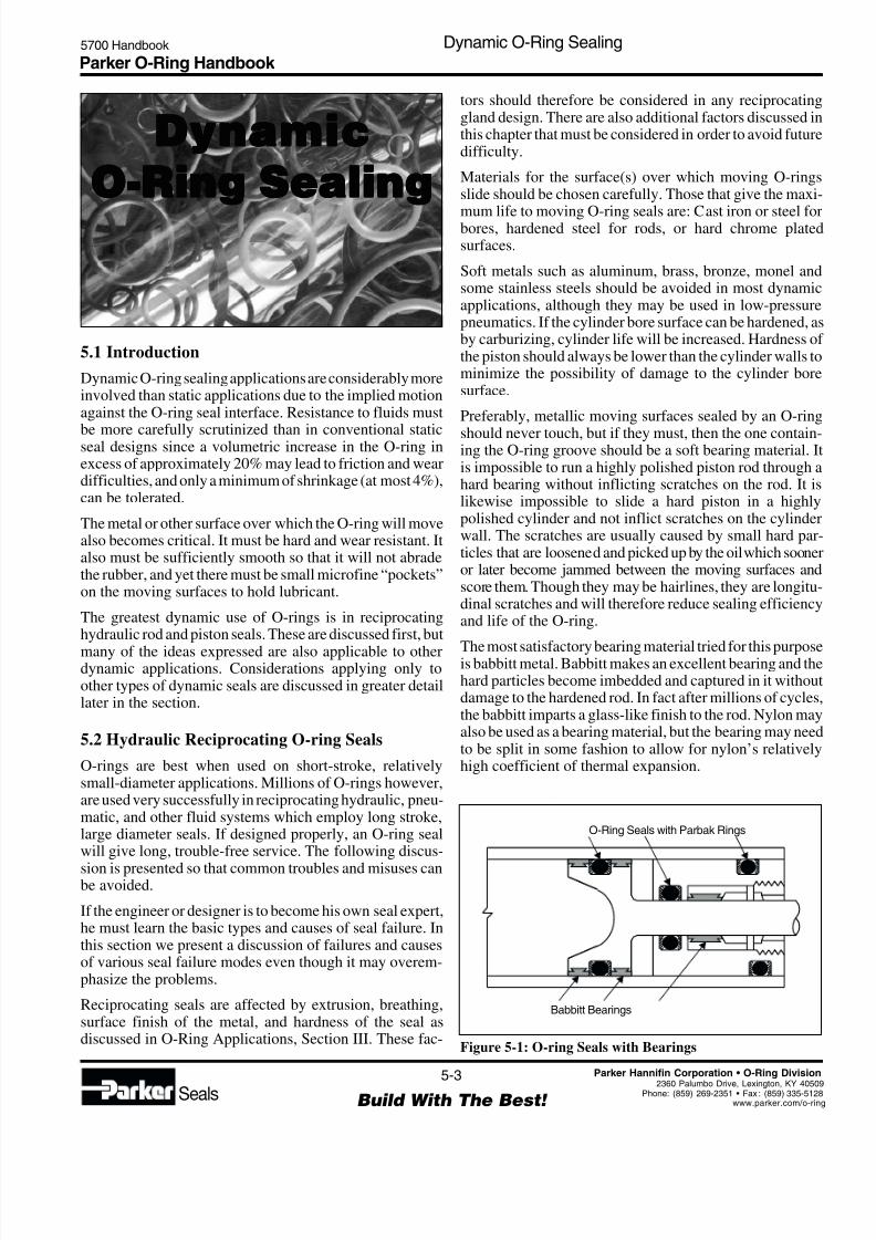
The most satisfactory bearing material tried for this purposeis babbitt metal. Babbitt makes an excellent bearing and thehard particles become imbedded and captured in it withoudamage to the hardened rod. In fact after millions of cyclesthe babbitt imparts a glass-like finish to the rod. Nylon mayalso be used as a bearing material, but the bearing may needto be split in some fashion to allow for nylon’s relativelyhigh coefficient of thermal expansion.
DynamicDynamicDynamicDynamicDynamic
O-Ring SealingO-Ring SealingO-Ring SealingO-Ring SealingO-Ring Sealing
Figure 5-1: O-ring Seals with Bearings
O-Ring Seals with Parbak Rings
Babbitt Bearings
8/6/2019 Dynamic Oring Sealing
http://slidepdf.com/reader/full/dynamic-oring-sealing 4/49
Parker O-Ring Handbook 5700 Handbook Dynamic O-Ring Sealing
5-4
Build With The Best! Seals
Parker Hannifin Corporation • O-Ring Division
2360 Palumbo Drive, Lexington, KY 40509Phone: (859) 269-2351 • Fax : (859) 335-5128www.parker.com/o-ring
Cut Wiper O-ringin Two to PreventPressure Trap
1/8 Ref.
FeltRing
3/18Ref.
Enlarged Viewof Felt WiperGland with FeltInstalled in Groovein Squeeze Condition
Cylinder End CapAlternate Design OneHole in Top of Cylinder
Prefered DesignOiling HoleDirect to Felt
Snap Ring
Washer
Scraper
Felt WiperO-ring Packing
Piston Rod
Bearing
In a suggested design, Figure 5-1, the piston is surfacedwith babbitt. The gland is also lined with babbitt. TheO-ring may be located in the babbitt lining or in thesupporting metal which should be relieved 0.051 or 0.076mm (0.002 or 0.003 inches) so there will be no chance of thehard metals running together.
Lubrication, as explained in O-Ring Application, SectionIII, is useful in all O-ring seals. It is doubly important indynamic applications where a lubricating film between theO-ring, and the surface it slides over, will protect the ringfrom abrasion, frictional heating and rapid wear.
In pneumatic applications, a back-up ring will trap somelubricant, and extend the useful life of seals that are lubri-cated infrequently. It will also help retain oil in applicationspowered with lubricated air.
When a cylinder rod extends out into a dirty environmentwhere it can pick up dirt, lint, metal chips, etc., this foreignmaterial can nullify the effect of the best lubricant and cause
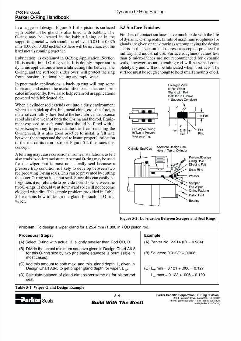
rapid abrasive wear of both the O-ring and the rod. Equip-ment exposed to such conditions should be fitted with awiper/scraper ring to prevent the dirt from reaching theO-ring seal. It is also good practice to install a felt ringbetween the scraper and the seal to insure proper lubricationof the rod on its return stroke. Figure 5-2 illustrates thisconcept.
A felt ring may cause corrosion in some installations, as feltalso tends to collect moisture. A second O-ring may be usedfor the wiper, but it must not actually seal because apressure trap condition is likely to develop between tworeciprocating O-ring seals. This can be prevented by cutting
the outer O-ring so it cannot seal. Since this can easily beforgotten, it is preferable to provide a vent hole between thetwo O-rings. It should vent downward so it will not becomeclogged with dirt. The sample problem provided in Table5-1 explains how to design the gland for such an O-ringwiper.
Problem: To design a wiper gland for a 25.4 mm (1.000 in.) OD piston rod.
Example:
(A) Parker No. 2-214 (ID = 0.984)
(B) Squeeze 0.012/2 = 0.006
(C) LW
min = 0.121 + .006 = 0.127
LW
max = 0.123 + .006 = 0.129
Figure 5-2: Lubrication Between Scraper and Seal Rings
5.3 Surface Finishes
Finishes of contact surfaces have much to do with the lifeof dynamic O-ring seals. Limits of maximum roughness forglands are given on the drawings accompanying the designcharts in this section and represent accepted practice formilitary and industrial use. Surface roughness values less
than 5 micro-inches are not recommended for dynamicseals, however, as an extending rod will be wiped com-pletely dry and will not be lubricated when it retracts. Thesurface must be rough enough to hold small amounts of oil.
Procedural Steps:
(A) Select O-ring with actual ID slightly smaller than Rod OD, B.
(B) Divide the actual minimum squeeze given in Design Chart A6-5for this O-ring size by two (the same squeeze is permissible inmost cases).
(C) Add this amount to both max. and min. gland depth, L, given inDesign Chart A6-5 to get proper gland depth for wiper, L
W.
(D) Calculate balance of gland dimensions same as for piston rodseal.
Table 5-1: Wiper Gland Design Example
8/6/2019 Dynamic Oring Sealing
http://slidepdf.com/reader/full/dynamic-oring-sealing 5/49
Parker O-Ring Handbook 5700 Handbook Dynamic O-Ring Sealing
5-5
Build With The Best! Seals
Parker Hannifin Corporation • O-Ring Division
2360 Palumbo Drive, Lexington, KY 4050Phone: (859) 269-2351 • Fax : (859) 335-512www.parker.com/o-rin
RV
aluein
m
a
µ
R Value in mz µ
0.160.25
0.400.63
1.01.6
2.5 6.3 16 40 100 2504.0 10 25 63 160
0.020
0.032
R
-Valuein
inch
a
µ
1
2
4
8
16
32
63
125
250
500
1000
2000
0.050
0.080
0.125
0.200
0.315
0.500
0.800
1.250
2.000
3.150
5.000
8.000
12.500
20.000
31.500
50.000
Deviation
Upper limitfor R when
transposingfrom R to R
a
z a
Upper limitfor R when
transposingfrom R to R
z
a z
Relationship Between R and Ra z
Ra
Ra
RzRz
Ideally, a microscopic “orange peel” type of surface is best,presenting smooth rounded surfaces for the O-ring to slideon, with small crevices between to act as oil reservoirs. Thiskind of surface may be approximated by peening the rodwith metal shot or glass beads. An even better surface canbe obtained by electropolishing. The most desirable surfaceroughness value is from 10 to 20 micro-inches.
The roughness of a surface as measured comprises severalelements which can be handled separately according toDIN 4760:
Level 1 — dimensional deviations withintolerance band
Level 2 — surface undulations (waves)Levels 3 to 5 — range of roughness
All these deviations from the ideal finish are superimposedas measurements are carried out and represent the surfaceroughness (see Figure 5-3).
Surface finish is often quantified in terms of Rt and Ra
(see Figure 5-4). R t is the vertical distance betweenthe highest and the lowest peaks in a roughness pro-file over a test length l
m. Rt is increasing being re-
placed by the maximum depth of roughness, Rmax. Rmax isthe greatest single roughness found in five consecutivesingle trace lengths l
m.
This is given in Figure 5-4 by the roughest profile Z4. In this
case Z4= Rmax does not include extreme roughness peaks as
is the case of Rt.
The medium roughness value Ra is an arithmetic mean of allcomponents of the roughness trace within the trace lengthlm. The average roughness value R
zof five consecutive
trace lengths often is preferred to Re.
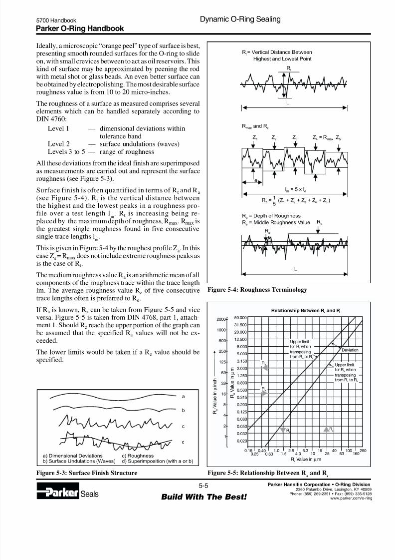
If Ra is known, Rz can be taken from Figure 5-5 and viceversa. Figure 5-5 is taken from DIN 4768, part 1, attach-ment 1. Should Rz reach the upper portion of the graph canbe assumed that the specified Ra values will not be ex-ceeded.
The lower limits would be taken if a Rz value should bespecified.
Figure 5-3: Surface Finish Structure
a
b
c
d
a) Dimensional Deviationsb) Surface Undulations (Waves)
c) Roughnessd) Superimposition (with a or b)
Figure 5-4: Roughness Terminology
Figure 5-5: Relationship Between Ra
and Rz
R = Vertical Distance Between
Highest and Lowest Pointt
R = Depth of Roughness
R = Middle Roughness Valuep
a
Rt
Rp
Ra
Z1
l = 5 x lm e
e
Z2 Z = R4 max
R = 15
(Z + Z + Z + Z + Z )z 1 2 3 4 5
Z5Z3
R and Rmax z
lm
lm
8/6/2019 Dynamic Oring Sealing
http://slidepdf.com/reader/full/dynamic-oring-sealing 6/49
Parker O-Ring Handbook 5700 Handbook Dynamic O-Ring Sealing
5-6
Build With The Best! Seals
Parker Hannifin Corporation • O-Ring Division
2360 Palumbo Drive, Lexington, KY 40509Phone: (859) 269-2351 • Fax : (859) 335-5128www.parker.com/o-ring
Table 5-2: Diagramatic Representation of Surface Profiles
Rt
Rp
Ra
tP
(%)
µm µm µm 0.25 0.50 0.75 Rt
1 0.5 0.5 50 50 50
1 0.5 0.5 50 50 75
1 0.5 0.5 50 50 75
1 0.75 0.28 12.5 25 37.5
1 0.25 0.28 62.5 75 87.5
1 0.785 0.188 3.5 14 35
1 0.215 0.188 65 86 96.5
1 0.5 0.39 43 50 57
Rp
1. Rt
Rp
2. Rt
Rp
3. Rt
Rp
4. Rt
Rp
5. Rt
Rp
6. Rt
Rp
7. Rt
Rp
8. R t
Finally, the depth of roughness Rp also is of interest and isthe vertical distance between the highest point on theroughness trace and the center line of that trace.
Values for Rt are of very little assistance in reaching aconclusion regarding the suitability of a surface roughnessfrom the sealing point of view. Table 5-1 shows that for a
similar Rt all levels of roughness can be produced. Ra valuesare unsuitable for comparison because profiles 6 and 7 havethe same Ra value. Rp values without reference to the loadarea t
palso gives a false impression of roughness.
A static sealing surface Rt ≤ 6.3 µm (VVV roughness DIN3141) is rougher than the dynamic surface requirements.Seal manufacturers recommend a roughness Rt ≤2.5 µm fora dynamic sealing surface (Ra = 0.25 to 0.5 mm) (VVV
roughness DIN 3141) when the load area is over 50%, orwhen the surface finish roughness Rp is under 50%. Theselimitations often are overlooked, nevertheless the connec-tion between surface finish and load area is very importantbecause an “open” profile can have sharp edges (e.g.,profiles 2 through 6 in Table 5-2). These open profiles area product of cutting processes such as turning or grinding.A much larger load area is produced by cold formingprocesses such as rolling, drawing or sinking.
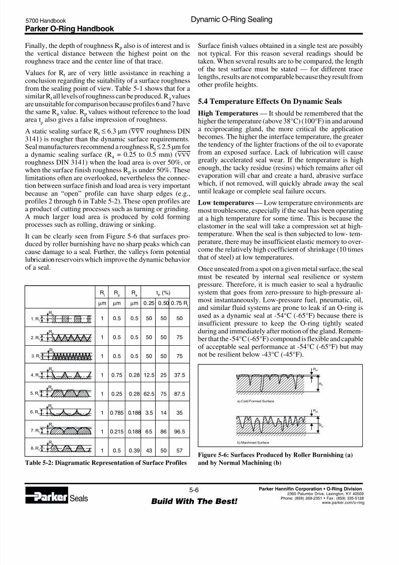
It can be clearly seen from Figure 5-6 that surfaces pro-duced by roller burnishing have no sharp peaks which cancause damage to a seal. Further, the valleys form potentiallubrication reservoirs which improve the dynamic behaviorof a seal.
Figure 5-6: Surfaces Produced by Roller Burnishing (a)
and by Normal Machining (b)
Rp1
Rt1
a) Cold Formed Surface
Rp2
Rt2
b) Machined Surface
Surface finish values obtained in a single test are possiblynot typical. For this reason several readings should betaken. When several results are to be compared, the lengthof the test surface must be stated — for different tracelengths, results are not comparable because they result fromother profile heights.
5.4 Temperature Effects On Dynamic Seals
High Temperatures — It should be remembered that thehigher the temperature (above 38°C) (100°F) in and arounda reciprocating gland, the more critical the applicationbecomes. The higher the interface temperature, the greaterthe tendency of the lighter fractions of the oil to evaporatefrom an exposed surface. Lack of lubrication will causegreatly accelerated seal wear. If the temperature is highenough, the tacky residue (resins) which remains after oilevaporation will char and create a hard, abrasive surfacewhich, if not removed, will quickly abrade away the sealuntil leakage or complete seal failure occurs.
Low temperatures — Low temperature environments aremost troublesome, especially if the seal has been operatingat a high temperature for some time. This is because theelastomer in the seal will take a compression set at high-temperature. When the seal is then subjected to low- tem-perature, there may be insufficient elastic memory to over-come the relatively high coefficient of shrinkage (10 timesthat of steel) at low temperatures.
Once unseated from a spot on a given metal surface, the sealmust be reseated by internal seal resilience or systempressure. Therefore, it is much easier to seal a hydraulicsystem that goes from zero-pressure to high-pressure al-most instantaneously. Low-pressure fuel, pneumatic, oil,and similar fluid systems are prone to leak if an O-ring isused as a dynamic seal at -54°C (-65°F) because there isinsufficient pressure to keep the O-ring tightly seatedduring and immediately after motion of the gland. Remem-ber that the -54°C (-65°F) compound is flexible and capableof acceptable seal performance at -54°C (-65°F) but maynot be resilient below -43°C (-45°F).

8/6/2019 Dynamic Oring Sealing
http://slidepdf.com/reader/full/dynamic-oring-sealing 7/49
Parker O-Ring Handbook 5700 Handbook Dynamic O-Ring Sealing
5-7
Build With The Best! Seals
Parker Hannifin Corporation • O-Ring Division
2360 Palumbo Drive, Lexington, KY 4050Phone: (859) 269-2351 • Fax : (859) 335-512www.parker.com/o-rin
5.5 Side Loads
Side loads on a piston or rod can cause the clearance in thegland to be on one side only. If excess clearance is createdby side-loading, extrusion will result. If adequate squeezehas not been applied, leakage will result. The higher unitload on the opposite side causes uneven friction on the seal,
and if high enough, the rod or barrel will be galled or scored.
5.6 Direction of Pressure
The placement of a groove can be determined from thedirection of the system pressure in relation to the directionof the moving friction force. If the friction of the movingmetal surface across the O-ring is in the same direction asthe direction of pressure, the O-ring will tend to be draggedinto the gap more readily and thus extrude at only 30 to 40%of the pressure normally necessary to cause extrusion. Byplacing the groove in the opposite metal part, any frictionwill work against pressure. Snubbing cylinders, in which
the motion and force create the pressure, are the usualculprits.
5.7 Shock Loads and Pressures
Shock pressures, such as those created by the suddenstopping of a rapidly descending hydraulic hoist cylinderon which there is a heavy load, are often far in excess of thepressure for which the seal and the system were designed.The same could be said about the whip of a gun barrel, of a tank on rough roads, or a truck tailgate and others if theyare designed to ride on the hydraulic system during transit.Transient pressures of 690 Bar (10,000 PSI) are not uncom-
mon in these cases. A mechanical lock or brake should beprovided to hold a position once it is attained. The hydrauliccylinder should be used only to raise and lower the load if it does not have a relief valve within it to prevent excessivepressure build-up by shock loads.
5.8 High Frequency Motion or Vibration
O-rings or other seals can be worn excessively by smallfrequent motions which are usually encountered whenequipment is in transit. For example: the tilt cylinder of a lifttruck, a hydraulic tailgate lift, and a road scraper blade.Normally, the hydraulic cylinder is intended as an actuator
and not as a locking device or a snubber. It will be noted thatbrick pavements and dirt roads cause the most trouble whenthis type of effect is encountered. A mechanical lock is alsorecommended as a cure in this case.
5.9 Squeeze
The best squeeze for a reciprocating O-ring seal must be acompromise of all the factors involved. The design tables inthis chapter are generally satisfactory. The greater thetemperature range to be sealed, the greater the squeeze that
is needed. The same is true if low pressure or vacuums areencountered. On the other hand, too much squeeze wilcause excessive friction, wear, and occasionally spiralfailure. Some rubber compounds require more squeeze thanothers in order to seal. The nitrile (buna-N) base com-pounds are recommended whenever possible because theyare more extrusion-resistant, more wear-resistant, and re-quire less squeeze to seal, than any other oil-resistant rubberdeveloped to date.
The military services have found that more than 0.432 mm(0.017") squeeze (per side) on a 5.334 mm (0.210") crosssection makes an O-ring prone to spiral failure. Yet muchless than this amount of squeeze will allow leakage at lowtemperature.
As discussed before, the amount of squeeze is a vital factorin friction. Therefore, one should carefully consider thesqueeze applied to the O-ring in any gland design.
Squeeze is actually necessary only during periods of very
low or no pressure sealing because at high pressures theO-ring seeks the path of least resistance, the clearance gapand tends to seal tighter and tighter as the pressure isincreased.
Enough squeeze must always be provided to offset the greadifference in coefficient of shrinkage of the rubber and themetal, take up the tolerances of the metal and rubber partsand compensate for the shrinkage (if any) of the rubber inthe fluid. The following example illustrates how the squeezecan vary in a typical piston installation:
Consider Parker size 2-012, and from Design Table 5-2
1.With perfect concentricityGland Depth, Lmax = 0.501 - 0.387 = 0.057
2
Radial clearance, max = 0.501 - 0.496 = 0.00252
Cross section, Wmin = .067
Reduction of W, due toinstallation stretch = 0.003 (see Figure 3-3)
Wmin, installed = 0.064
less Lmax = 0.057 (from 1. above)
squeeze, min = 0.007
2.With maximum radial displacement (piston tangentwith bore)
squeeze, min = 0.007 (from 1. above)
radial piston shift, max = 0.0025
squeeze = 0.0045 min possible
3.With maximum eccentricity of 0.002 T.I.R. betweenpiston and groove OD
squeeze, min = 0.0045 (from 2. above)
radial groove shift, max = 0.0010
8/6/2019 Dynamic Oring Sealing
http://slidepdf.com/reader/full/dynamic-oring-sealing 8/49
Parker O-Ring Handbook 5700 Handbook Dynamic O-Ring Sealing
5-8
Build With The Best! Seals
Parker Hannifin Corporation • O-Ring Division
2360 Palumbo Drive, Lexington, KY 40509Phone: (859) 269-2351 • Fax : (859) 335-5128www.parker.com/o-ring
squeeze, min. = 0.0035 with adversetolerance build-up.
If the O-ring is made in a compound that will shrink in thefluid, the minimum possible squeeze under adverse condi-tions then must be at least .076 mm (.003").
5.10 StretchWhen an O-ring must be stretched more than two or threepercent as installed in a piston groove, the reduction in thesqueeze diameter that results should be allowed for indetermining the gland depth so that the desired percentsqueeze will be applied to the reduced section. The percentof stretch should therefore be checked whenever the cataloggland dimensions are not used.
Large diameter O-rings may fit the piston so loosely thatthey must be carefully stuffed into the groove as the pistonenters the cylinder to prevent damage. For these, the dangerof damage is reduced if the next smaller size O-ring is used.
Since this will likely cause a stretch close to five percent, itwill usually be necessary to adjust the gland depth asmentioned above. See Figure 3-3 for the reduction insqueeze diameter with stretch.
5.11 Friction
Friction, either break-out, running, or both, can becometroublesome in some applications. At any given time, thereare anomalies and difficulties in the prediction of devel-oped friction. These are accentuated if one of the surfacesinvolved is deformable as in O-ring piston or shaft seals. Anunderstanding of the principles may prove helpful in the
solution of specific problems.
5.11.1 Break-Out Friction
In addition to the usual causes of running friction: hardnessof the rubber, type of surface, surface finish, squeeze on theO-ring, amount and type of lubrication, fluid pressure/ temperature, the amount of break-out friction which a
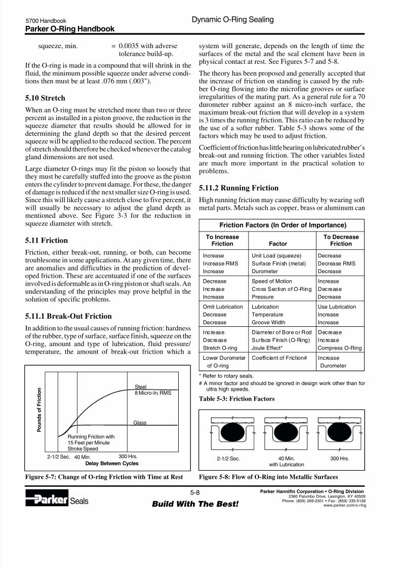
system will generate, depends on the length of time thesurfaces of the metal and the seal element have been inphysical contact at rest. See Figures 5-7 and 5-8.
The theory has been proposed and generally accepted thatthe increase of friction on standing is caused by the rub-ber O-ring flowing into the microfine grooves or surface
irregularities of the mating part. As a general rule for a 70durometer rubber against an 8 micro-inch surface, themaximum break-out friction that will develop in a systemis 3 times the running friction. This ratio can be reduced bythe use of a softer rubber. Table 5-3 shows some of thefactors which may be used to adjust friction.
Coefficient of friction has little bearing on lubricated rubber’sbreak-out and running friction. The other variables listedare much more important in the practical solution toproblems.
5.11.2 Running Friction
High running friction may cause difficulty by wearing softmetal parts. Metals such as copper, brass or aluminum can
Figure 5-7: Change of O-ring Friction with Time at Rest
PoundsofFrict
ion Steel
8 Micro-In. RMS
Glass
Running Friction with15 Feet per MinuteStroke Speed
2-1/2 Sec. 40 Min.Delay Between Cycles
300 Hrs.
Friction Factors (In Order of Importance)
To Increase To DecreaseFriction Factor Friction
Increase Unit Load (squeeze) Decrease
Increase RMS Surface Finish (metal) Decrease RMS
Increase Durometer Decrease
Decrease Speed of Motion Increase
Increase Cross Section of O-Ring Decrease
Increase Pressure DecreaseOmit Lubrication Lubrication Use Lubrication
Decrease Temperature Increase
Decrease Groove Width Increase
Increase Diameter of Bore or Rod Decrease
Decrease Surface Finish (O-Ring) Increase
Stretch O-ring Joule Effect* Compress O-Ring
Lower Durometer Coefficient of Friction# Increase
of O-ring Durometer
* Refer to rotary seals.
# A minor factor and should be ignored in design work other than forultra high speeds.
Table 5-3: Friction Factors
Figure 5-8: Flow of O-Ring into Metallic Surfaces
2-1/2 Sec. 40 Min.with Lubrication
300 Hrs.
8/6/2019 Dynamic Oring Sealing
http://slidepdf.com/reader/full/dynamic-oring-sealing 9/49
Parker O-Ring Handbook 5700 Handbook Dynamic O-Ring Sealing
5-9
Build With The Best! Seals
Parker Hannifin Corporation • O-Ring Division
2360 Palumbo Drive, Lexington, KY 4050Phone: (859) 269-2351 • Fax : (859) 335-512www.parker.com/o-rin
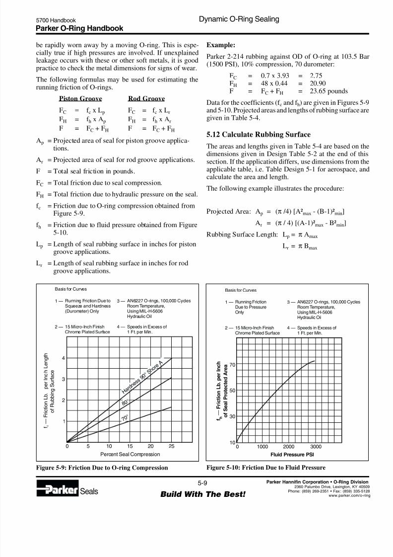
Figure 5-9: Friction Due to O-ring Compression Figure 5-10: Friction Due to Fluid Pressure
Percent Seal Compression
H a r d n e s s
9 0 ° S h o
r eA
7 0 °
8 0 °
f —
F r i c t i o n
L b .
p e r
I n c
h L
e n g
t h
o f
R u
b b i n g
S u r f a c e
c
4
3
2
1
0 5 10 15 20 25
Basis for Curves
Running Friction Due toSqueeze and Hardness(Durometer) Only
15 Micro-Inch FinishChrome Plated Surface
1 —
2 —
AN6227 O-rings, 100,000 CyclesRoom Temperature,Using MIL-H-5606Hydraulic Oil
Speeds in Excess of1 Ft. per Min.
3 —
4 —
Fluid Pressure PSI
f—FrictionL
b.perInch
ofSealProte
ctedArea
h
70
50
30
010
1000 2000 3000
Basis for Curves
Running FrictionDue to PressureOnly
15 Micro-Inch FinishChrome Plated Surface
1 —
2 —
AN6227 O-rings, 100,000 CyclesRoom Temperature,Using MIL-H-5606Hydraulic Oil
Speeds in Excess of1 Ft. per Min.
3 —
4 —
be rapidly worn away by a moving O-ring. This is espe-cially true if high pressures are involved. If unexplainedleakage occurs with these or other soft metals, it is goodpractice to check the metal dimensions for signs of wear.
The following formulas may be used for estimating therunning friction of O-rings.
Piston Groove Rod Groove
FC = f c x Lp FC = f c x Lr
FH = f h x Ap FH = f h x Ar
F = FC + FH F = FC + FH
Ap = Projected area of seal for piston groove applica-tions.
Ar = Projected area of seal for rod groove applications.
F = Total seal friction in pounds.
FC = Total friction due to seal compression.
FH = Total friction due to hydraulic pressure on the seal.f c = Friction due to O-ring compression obtained from
Figure 5-9.
f h = Friction due to fluid pressure obtained from Figure5-10.
Lp = Length of seal rubbing surface in inches for pistongroove applications.
Lr = Length of seal rubbing surface in inches for rodgroove applications.
Example:
Parker 2-214 rubbing against OD of O-ring at 103.5 Bar(1500 PSI), 10% compression, 70 durometer:
FC = 0.7 x 3.93 = 2.75FH = 48 x 0.44 = 20.90F = FC + FH = 23.65 pounds
Data for the coefficients (f c and f h) are given in Figures 5-9and 5-10. Projected areas and lengths of rubbing surface aregiven in Table 5-4.
5.12 Calculate Rubbing Surface
The areas and lengths given in Table 5-4 are based on thedimensions given in Design Table 5-2 at the end of thissection. If the application differs, use dimensions from theapplicable table, i.e. Table Design 5-1 for aerospace, andcalculate the area and length.
The following example illustrates the procedure:
Projected Area: Ap = (π /4) [A²max - (B-1)²min]
Ar = (π / 4) [(A-1)²max - B²min]
Rubbing Surface Length: Lp = π Amax
Lr = π Bmax
8/6/2019 Dynamic Oring Sealing
http://slidepdf.com/reader/full/dynamic-oring-sealing 10/49
Parker O-Ring Handbook 5700 Handbook Dynamic O-Ring Sealing
5-10
Build With The Best! Seals
Parker Hannifin Corporation • O-Ring Division
2360 Palumbo Drive, Lexington, KY 40509Phone: (859) 269-2351 • Fax : (859) 335-5128www.parker.com/o-ring
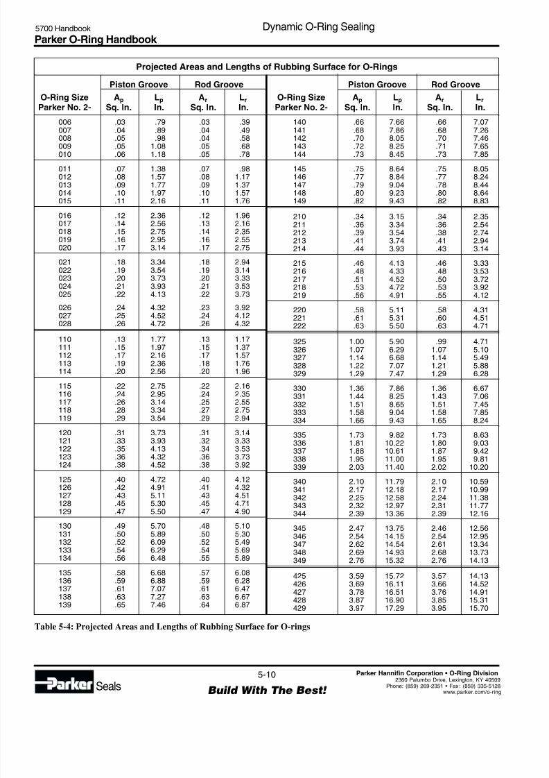
Projected Areas and Lengths of Rubbing Surface for O-Rings
Piston Groove Rod Groove
O-Ring Size Ap Lp Ar Lr
Parker No. 2- Sq. In. In. Sq. In. In.
006 .03 .79 .03 .39007 .04 .89 .04 .49
008 .05 .98 .04 .58009 .05 1.08 .05 .68010 .06 1.18 .05 .78
011 .07 1.38 .07 .98012 .08 1.57 .08 1.17013 .09 1.77 .09 1.37014 .10 1.97 .10 1.57015 .11 2.16 .11 1.76
016 .12 2.36 .12 1.96017 .14 2.56 .13 2.16018 .15 2.75 .14 2.35019 .16 2.95 .16 2.55020 .17 3.14 .17 2.75
021 .18 3.34 .18 2.94
022 .19 3.54 .19 3.14023 .20 3.73 .20 3.33024 .21 3.93 .21 3.53025 .22 4.13 .22 3.73
026 .24 4.32 .23 3.92027 .25 4.52 .24 4.12028 .26 4.72 .26 4.32
110 .13 1.77 .13 1.17111 .15 1.97 .15 1.37112 .17 2.16 .17 1.57113 .19 2.36 .18 1.76114 .20 2.56 .20 1.96
115 .22 2.75 .22 2.16116 .24 2.95 .24 2.35117 .26 3.14 .25 2.55
118 .28 3.34 .27 2.75119 .29 3.54 .29 2.94
120 .31 3.73 .31 3.14121 .33 3.93 .32 3.33122 .35 4.13 .34 3.53123 .36 4.32 .36 3.73124 .38 4.52 .38 3.92
125 .40 4.72 .40 4.12126 .42 4.91 .41 4.32127 .43 5.11 .43 4.51128 .45 5.30 .45 4.71129 .47 5.50 .47 4.90
130 .49 5.70 .48 5.10131 .50 5.89 .50 5.30
132 .52 6.09 .52 5.49133 .54 6.29 .54 5.69134 .56 6.48 .55 5.89
135 .58 6.68 .57 6.08136 .59 6.88 .59 6.28137 .61 7.07 .61 6.47138 .63 7.27 .63 6.67139 .65 7.46 .64 6.87
140 .66 7.66 .66 7.07141 .68 7.86 .68 7.26
142 .70 8.05 .70 7.46143 .72 8.25 .71 7.65144 .73 8.45 .73 7.85
145 .75 8.64 .75 8.05146 .77 8.84 .77 8.24147 .79 9.04 .78 8.44148 .80 9.23 .80 8.64149 .82 9.43 .82 8.83
210 .34 3.15 .34 2.35211 .36 3.34 .36 2.54212 .39 3.54 .38 2.74213 .41 3.74 .41 2.94214 .44 3.93 .43 3.14
215 .46 4.13 .46 3.33
216 .48 4.33 .48 3.53217 .51 4.52 .50 3.72218 .53 4.72 .53 3.92219 .56 4.91 .55 4.12
220 .58 5.11 .58 4.31221 .61 5.31 .60 4.51222 .63 5.50 .63 4.71
325 1.00 5.90 .99 4.71326 1.07 6.29 1.07 5.10327 1.14 6.68 1.14 5.49328 1.22 7.07 1.21 5.88329 1.29 7.47 1.29 6.28
330 1.36 7.86 1.36 6.67331 1.44 8.25 1.43 7.06332 1.51 8.65 1.51 7.45333 1.58 9.04 1.58 7.85334 1.66 9.43 1.65 8.24
335 1.73 9.82 1.73 8.63336 1.81 10.22 1.80 9.03337 1.88 10.61 1.87 9.42338 1.95 11.00 1.95 9.81339 2.03 11.40 2.02 10.20
340 2.10 11.79 2.10 10.59341 2.17 12.18 2.17 10.99342 2.25 12.58 2.24 11.38343 2.32 12.97 2.31 11.77344 2.39 13.36 2.39 12.16
345 2.47 13.75 2.46 12.56346 2.54 14.15 2.54 12.95
347 2.62 14.54 2.61 13.34348 2.69 14.93 2.68 13.73349 2.76 15.32 2.76 14.13
425 3.59 15.72 3.57 14.13426 3.69 16.11 3.66 14.52427 3.78 16.51 3.76 14.91428 3.87 16.90 3.85 15.31429 3.97 17.29 3.95 15.70
Piston Groove Rod Groove
O-Ring Size Ap Lp Ar Lr
Parker No. 2- Sq. In. In. Sq. In. In.
Table 5-4: Projected Areas and Lengths of Rubbing Surface for O-rings
8/6/2019 Dynamic Oring Sealing
http://slidepdf.com/reader/full/dynamic-oring-sealing 11/49
Parker O-Ring Handbook 5700 Handbook Dynamic O-Ring Sealing
5-11
Build With The Best! Seals
Parker Hannifin Corporation • O-Ring Division
2360 Palumbo Drive, Lexington, KY 4050Phone: (859) 269-2351 • Fax : (859) 335-512www.parker.com/o-rin
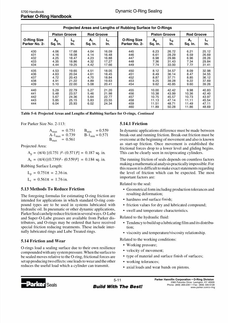
Table 5-4: Projected Areas and Lengths of Rubbing Surface for O-rings, Continued
430 4.06 17.68 4.04 16.09431 4.16 18.08 4.14 16.48432 4.25 18.47 4.23 16.88433 4.35 18.86 4.32 17.27434 4.44 19.25 4.42 17.66
435 4.53 19.65 4.51 18.05436 4.63 20.04 4.61 18.45437 4.72 20.43 4.70 18.84438 4.91 21.22 4.89 19.63439 5.10 22.00 5.08 20.41
440 5.29 22.79 5.27 21.20441 5.48 23.57 5.46 21.98442 5.67 24.36 5.64 22.77443 5.85 25.15 5.83 23.55444 6.04 25.93 6.02 24.34
Projected Areas and Lengths of Rubbing Surface for O-Rings
Piston Groove Rod Groove
O-Ring Size Ap Lp Ar Lr
Parker No. 2- Sq. In. In. Sq. In. In.
Piston Groove Rod Groove
O-Ring Size Ap Lp Ar Lr
Parker No. 2- Sq. In. In. Sq. In. In.
445 6.23 26.72 6.21 25.12446 6.61 28.29 6.59 26.69447 6.98 29.86 6.96 28.26448 7.36 31.43 7.34 29.84449 7.74 33.00 7.72 31.41
450 8.12 34.57 8.09 32.98451 8.49 36.14 8.47 34.55452 8.87 37.71 8.85 36.12453 9.25 39.28 9.22 37.69454 9.62 40.85 9.60 39.26
455 10.00 42.42 9.98 40.83456 10.38 43.99 10.36 42.40457 10.75 45.57 10.73 43.97458 11.13 47.14 11.11 45.54459 11.51 48.71 11.49 47.11460 11.89 50.28 11.86 48.69
For Parker Size No. 2-113:
Amax = 0.751 Bmin = 0.559A-1max = 0.739 B-1min = 0.571Bmax = 0.561
Projected Area:
Ap = (π /4) [(0.751 )²- (0.571)²] = 0.187 sq. in.
Ar = (π /4) [(0.739)² - (0.559)²] = 0.184 sq. in.
Rubbing Surface Length:
Lp = 0.751π = 2.36 in.
Lr = 0.561π = 1.76 in.
5.13 Methods To Reduce Friction
The foregoing formulas for estimating O-ring friction areintended for applications in which standard O-ring com-pound types are to be used in systems lubricated withhydraulic oil. In pneumatic or other dynamic applications,Parker Seal can help reduce friction in several ways. O-Lubeand Super-O-Lube greases are available from Parker dis-tributors, and O-rings may be ordered that have received
special friction reducing treatments. These include inter-nally lubricated rings and Lube Treated rings.
5.14 Friction and Wear
O-rings load a sealing surface due to their own resiliencecompounded with any system pressure. When the surface tobe sealed moves relative to the O-ring, frictional forces areset up producing two effects: one leads to wear and the otherreduces the useful load which a cylinder can transmit.
5.14.1 Friction
In dynamic applications difference must be made betweenbreak-out and running friction. Break-out friction must beovercome at the beginning of movement and also is knownas start-up friction. Once movement is established thefrictional forces drop to a lower level and gliding beginsThis can be clearly seen in reciprocating cylinders.
The running friction of seals depends on countless factorsmaking a mathematical analysis practically impossible. For
this reason it is difficult to make exact statements regardingthe level of friction which can be expected. The mosimportant factors are:
Related to the seal:
• Geometrical form including production tolerances andresulting deformation;
• hardness and surface finish;
• friction values for dry and lubricated compound;
• swell and temperature characteristics.
Related to the hydraulic fluid:
• Tendency to build up a lubricating film and its distribu-
tion;
• viscosity and temperature/viscosity relationship.
Related to the working conditions:
• Working pressure;
• velocity of movement;
• type of material and surface finish of surfaces;
• working tolerances;
• axial loads and wear bands on pistons.
8/6/2019 Dynamic Oring Sealing
http://slidepdf.com/reader/full/dynamic-oring-sealing 12/49
Parker O-Ring Handbook 5700 Handbook Dynamic O-Ring Sealing
5-12
Build With The Best! Seals
Parker Hannifin Corporation • O-Ring Division
2360 Palumbo Drive, Lexington, KY 40509Phone: (859) 269-2351 • Fax : (859) 335-5128www.parker.com/o-ring
These factors cannot be quantified because they overlapand act cumulatively.
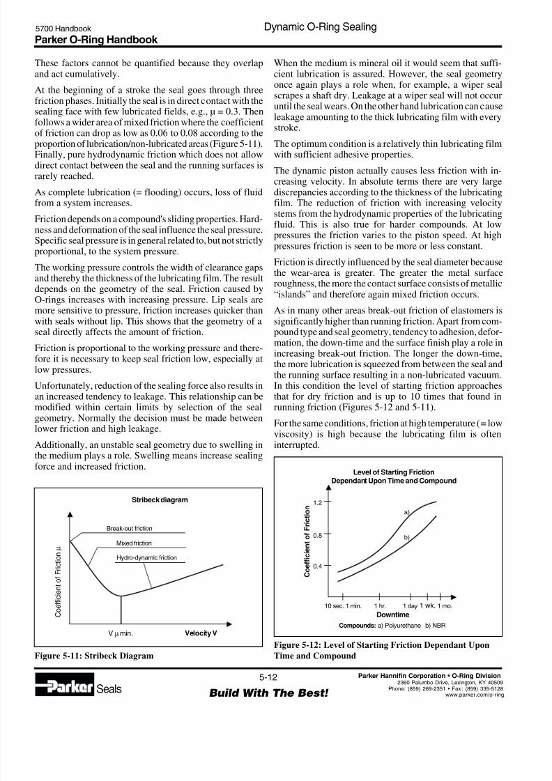
At the beginning of a stroke the seal goes through threefriction phases. Initially the seal is in direct contact with thesealing face with few lubricated fields, e.g., µ = 0.3. Thenfollows a wider area of mixed friction where the coefficient
of friction can drop as low as 0.06 to 0.08 according to theproportion of lubrication/non-lubricated areas (Figure 5-11).Finally, pure hydrodynamic friction which does not allowdirect contact between the seal and the running surfaces israrely reached.
As complete lubrication (= flooding) occurs, loss of fluidfrom a system increases.
Friction depends on a compound's sliding properties. Hard-ness and deformation of the seal influence the seal pressure.Specific seal pressure is in general related to, but not strictlyproportional, to the system pressure.
The working pressure controls the width of clearance gapsand thereby the thickness of the lubricating film. The resultdepends on the geometry of the seal. Friction caused byO-rings increases with increasing pressure. Lip seals aremore sensitive to pressure, friction increases quicker thanwith seals without lip. This shows that the geometry of aseal directly affects the amount of friction.
Friction is proportional to the working pressure and there-fore it is necessary to keep seal friction low, especially atlow pressures.
Unfortunately, reduction of the sealing force also results inan increased tendency to leakage. This relationship can be
modified within certain limits by selection of the sealgeometry. Normally the decision must be made betweenlower friction and high leakage.
Additionally, an unstable seal geometry due to swelling inthe medium plays a role. Swelling means increase sealingforce and increased friction.
When the medium is mineral oil it would seem that suffi-cient lubrication is assured. However, the seal geometryonce again plays a role when, for example, a wiper sealscrapes a shaft dry. Leakage at a wiper seal will not occuruntil the seal wears. On the other hand lubrication can causeleakage amounting to the thick lubricating film with everystroke.
The optimum condition is a relatively thin lubricating filmwith sufficient adhesive properties.
The dynamic piston actually causes less friction with in-creasing velocity. In absolute terms there are very largediscrepancies according to the thickness of the lubricatingfilm. The reduction of friction with increasing velocitystems from the hydrodynamic properties of the lubricatingfluid. This is also true for harder compounds. At lowpressures the friction varies to the piston speed. At highpressures friction is seen to be more or less constant.
Friction is directly influenced by the seal diameter because
the wear-area is greater. The greater the metal surfaceroughness, the more the contact surface consists of metallic“islands” and therefore again mixed friction occurs.
As in many other areas break-out friction of elastomers issignificantly higher than running friction. Apart from com-pound type and seal geometry, tendency to adhesion, defor-mation, the down-time and the surface finish play a role inincreasing break-out friction. The longer the down-time,the more lubrication is squeezed from between the seal andthe running surface resulting in a non-lubricated vacuum.In this condition the level of starting friction approachesthat for dry friction and is up to 10 times that found in
running friction (Figures 5-12 and 5-11).For the same conditions, friction at high temperature (= lowviscosity) is high because the lubricating film is ofteninterrupted.
Figure 5-11: Stribeck Diagram
Velocity VV min.µ
CoefficientofFriction
µ
Mixed friction
Break-out friction
Hydro-dynamic friction
Stribeck diagram
Figure 5-12: Level of Starting Friction Dependant Upon
Time and Compound
Downtime
10 sec. 1 min. 1 hr. 1 day 1 wk. 1 mo.
a)
Compounds: a) Polyurethane b) NBR
b)
0.4
0.8
1.2
CoefficientofFriction
Level of Starting FrictionDependant Upon Time and Compound

8/6/2019 Dynamic Oring Sealing
http://slidepdf.com/reader/full/dynamic-oring-sealing 13/49
Parker O-Ring Handbook 5700 Handbook Dynamic O-Ring Sealing
5-13
Build With The Best! Seals
Parker Hannifin Corporation • O-Ring Division
2360 Palumbo Drive, Lexington, KY 4050Phone: (859) 269-2351 • Fax : (859) 335-512www.parker.com/o-rin
The most important factors can be seen in Figure 5-13. Herefriction is shown as a function of pressure and velocity.Figure 5-13 is valid only for a specific seal in a particularapplication. For other seals and applications the interde-pendence varies.
The stick-slip effect also is related to the friction at the
sealing face. The friction, or better expressed the differencebetween break-out and running friction, plays an importantrole in evaluation and selection of a suitable elastomer.
Break-out friction occurs when the three following condi-tions are present:
• When the break-out friction is higher than the runningfriction a running velocity Vµ min (see Figure 5-11);
• the running velocity is Vµ min;
• the power is transmitted through the elastic body of the“compressible” oil.
To assist in the explanation of the term stick-slip, please
refer to Figure 5-14. To accelerate a mass m from zero tomaximum velocity, the break-out friction µH must beovercome by F1. The spring element is loaded with F1 andwith increasing velocity the friction value µH reduces toµG and the force to F2. The potential energy stored in thespring accelerates the mass even further. When the storedenergy is used, the mass is decelerated by the increasingfriction in direction µH. This requires once again an in-crease in force level of F1, and the procedure repeats again.
Running velocity is a product of seal friction, the pistonmass and the load. Of all these factors, only friction can beinfluenced and makes for a better relationship betweensealing surface finish, lubricating film and surface finishrunning very important. Certain improvements can be mademaking the system stiffer, this means the smallest possibleoil volume under pressure on the hydraulic side.
Radial oscillation of the piston will occur when the lubricat-ing film breaks down. Conversely oils with strong filmbuilding properties do not break down under the sameworking conditions using the same seals.
5.14.2 Pneumatic Seals
In principle the same conditions apply here as for thehydraulic seal, except that the effects of certain extremeconditions are more serious. This is particularly the casewhen lubrication is poor, as found when lubricated air is notavailable. Lubricated air gives more or less the same results
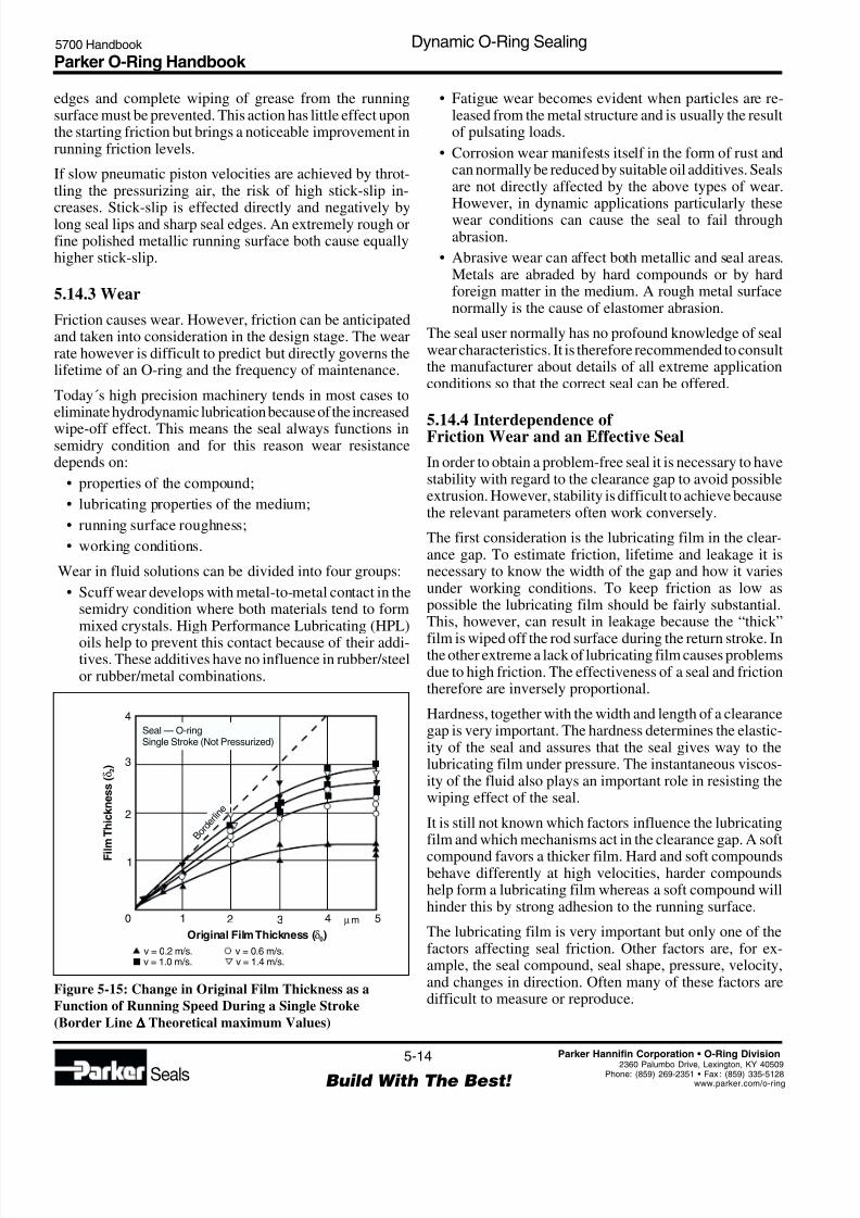
as in a hydraulic application.When lubricating grease is not continually replaced, it caneventually be removed by a seal lip. The effectiveness oflubrication with grease depends on the thickness of theoriginal film and the running velocity of the seal (Figure5-15).
The lower the velocity the thinner will become the lubricat-ing film. With an O-ring seal the loss of grease can lead tototal breakdown of the hydrodynamic lubricating film afteronly a few slow strokes.
Breakdown of the lubricating film after long operation alsoresults in contact between the seal and the metal surfacesThis makes the seal move in the mixed friction range, theincrease in friction causes high wear. The lubricating filmtherefore must be protected by rounding of the seal wiper
Figure 5-14: System Diagram for Stick-Slip Effect
Velocity (V)V min.µ
µ
µH
µGCoeffic
ientofFriction µ
F m
P r e s
s u r e
P( b a r )V e l o c i t y V ( m / m m )
F r i c t i o n a l
F o r c e
F
( k N )
0
100
3
0.5
1.0
1.5
2
1
200
Figure 5-13: Frictional Force is Dependent Upon Pressure
and Velocity – Compact Rod Seal 90° Shore A
8/6/2019 Dynamic Oring Sealing
http://slidepdf.com/reader/full/dynamic-oring-sealing 14/49
Parker O-Ring Handbook 5700 Handbook Dynamic O-Ring Sealing
5-14
Build With The Best! Seals
Parker Hannifin Corporation • O-Ring Division
2360 Palumbo Drive, Lexington, KY 40509Phone: (859) 269-2351 • Fax : (859) 335-5128www.parker.com/o-ring
edges and complete wiping of grease from the runningsurface must be prevented. This action has little effect uponthe starting friction but brings a noticeable improvement inrunning friction levels.
If slow pneumatic piston velocities are achieved by throt-tling the pressurizing air, the risk of high stick-slip in-
creases. Stick-slip is effected directly and negatively bylong seal lips and sharp seal edges. An extremely rough orfine polished metallic running surface both cause equallyhigher stick-slip.
5.14.3 Wear
Friction causes wear. However, friction can be anticipatedand taken into consideration in the design stage. The wearrate however is difficult to predict but directly governs thelifetime of an O-ring and the frequency of maintenance.
Today´s high precision machinery tends in most cases toeliminate hydrodynamic lubrication because of the increased
wipe-off effect. This means the seal always functions insemidry condition and for this reason wear resistancedepends on:
• properties of the compound;
• lubricating properties of the medium;
• running surface roughness;
• working conditions.
Wear in fluid solutions can be divided into four groups:
• Scuff wear develops with metal-to-metal contact in thesemidry condition where both materials tend to formmixed crystals. High Performance Lubricating (HPL)
oils help to prevent this contact because of their addi-tives. These additives have no influence in rubber/steelor rubber/metal combinations.
• Fatigue wear becomes evident when particles are re-leased from the metal structure and is usually the resultof pulsating loads.
• Corrosion wear manifests itself in the form of rust andcan normally be reduced by suitable oil additives. Sealsare not directly affected by the above types of wear.However, in dynamic applications particularly thesewear conditions can cause the seal to fail throughabrasion.
• Abrasive wear can affect both metallic and seal areas.Metals are abraded by hard compounds or by hardforeign matter in the medium. A rough metal surfacenormally is the cause of elastomer abrasion.
The seal user normally has no profound knowledge of sealwear characteristics. It is therefore recommended to consultthe manufacturer about details of all extreme applicationconditions so that the correct seal can be offered.
5.14.4 Interdependence of Friction Wear and an Effective Seal
In order to obtain a problem-free seal it is necessary to havestability with regard to the clearance gap to avoid possibleextrusion. However, stability is difficult to achieve becausethe relevant parameters often work conversely.
The first consideration is the lubricating film in the clear-ance gap. To estimate friction, lifetime and leakage it isnecessary to know the width of the gap and how it variesunder working conditions. To keep friction as low aspossible the lubricating film should be fairly substantial.This, however, can result in leakage because the “thick”
film is wiped off the rod surface during the return stroke. Inthe other extreme a lack of lubricating film causes problemsdue to high friction. The effectiveness of a seal and frictiontherefore are inversely proportional.
Hardness, together with the width and length of a clearancegap is very important. The hardness determines the elastic-ity of the seal and assures that the seal gives way to thelubricating film under pressure. The instantaneous viscos-ity of the fluid also plays an important role in resisting thewiping effect of the seal.
It is still not known which factors influence the lubricatingfilm and which mechanisms act in the clearance gap. A soft
compound favors a thicker film. Hard and soft compoundsbehave differently at high velocities, harder compoundshelp form a lubricating film whereas a soft compound willhinder this by strong adhesion to the running surface.
The lubricating film is very important but only one of thefactors affecting seal friction. Other factors are, for ex-ample, the seal compound, seal shape, pressure, velocity,and changes in direction. Often many of these factors aredifficult to measure or reproduce.
Figure 5-15: Change in Original Film Thickness as a
Function of Running Speed During a Single Stroke
(Border Line ∆∆∆∆∆ Theoretical maximum Values)
B o r d e r l i n
e
Fil
mThickness(
) δ
2
Original FilmThickness ( )δ0
4
3
2
1
0 1 2 3 4 5
v = 0.2 m/s. v = 0.6 m/s.
µm
v = 1.4 m/s.v = 1.0 m/s.
Seal — O-ringSingle Stroke (Not Pressurized)

8/6/2019 Dynamic Oring Sealing
http://slidepdf.com/reader/full/dynamic-oring-sealing 15/49
Parker O-Ring Handbook 5700 Handbook Dynamic O-Ring Sealing
5-15
Build With The Best! Seals
Parker Hannifin Corporation • O-Ring Division
2360 Palumbo Drive, Lexington, KY 4050Phone: (859) 269-2351 • Fax : (859) 335-512www.parker.com/o-rin
It is therefore quite understandable that seal manufacturerscannot give customers fixed figures regarding friction andwear for an individual seal. Information about seal lifetimesonly can be made when all parameters affecting the seal areknown and reproducible. General assumptions from a fewtests are not acceptable because laboratory tests never canreproduce real working situations.
5.15 Spiral Failure
A unique type of failure sometimes occurs on reciprocatingO-rings which is called spiral failure. This name was givento this type of failure because when it occurs the seal looksas if it had been cut about halfway through the O-ring crosssection in a spiral or corkscrew pattern. Oddly enough, theO-ring usually seals satisfactorily until a complete break orseparation occurs at one place. Sometimes the seal istwisted in two without evidence of the spiral pattern, but ingeneral, the same factors cause the break.
A properly used O-ring slides during all but a small fractionof any reciprocating stroke. This type of seal does notnormally tend to roll or twist because:
1. The hydraulic pressure, acting through the O-ring,produces a greater holding force within the groove(friction on a larger area) than that produced by thesliding surface (rod or cylinder wall) opposite thegroove (see Figure 5-16).
2. The smoother finish of the sliding surface, in rela-tion to the groove surface-finish, produces lessfriction.
3. Running friction is lower than break-out friction.
4. The torsional resistance of the O-ring tends to resisttwisting.
The conditions which cause spiral failure are those thatsimultaneously cause segments of the ring to slide andothers to roll. A small amount of twisting is not detrimentalbut, when excessive, torsional failure or spiral failure willoccur. True spiral failure occurs after the seal has beenexcessively twisted, but not broken, and then subjected torelatively high pressure. The twisted seal is forced into thesharp corner at the clearance gap by the pressure which putsan additional stress on this portion of the seal. Rapid stress-aging, or stress above the elastic limit of the rubber, causes
a rupture of the O-ring to start adjacent to the clearance gap.Slight flexing, motion, or working of the O-ring apparentlycauses the rupture to penetrate about half way through thecross section. When the O-ring is removed from the gland,it returns to its original shape and the rupture appears as atight spiral around the cross section.
Torsional or spiral failure is not limited to the O-ring ortorus type of seal. Square, delta, four-leaf clover, and othercross sectional shapes (see Figure 5-17) are also prone tofail by twisting if the proper conditions exist.
Figure 5-16: Action of Fluid Pressure to Prevent Rolling
of O-ring
FluidPressure
Shaft Small Area
LargeArea
Figure 5-17: Ring Cross-Sections for Reciprocating Seals
O-Ring Square-Ring Delta-RingX-Ring
All are subject to torsional or spiral failure.
The design and operational factors which contribute tospiral failure of a seal are listed below in the order of theirrelative importance:
1. Speed of stroke
2. Lack of lubrication
3. Pressure differential and direction
4. Squeeze5. Shape of groove or split grooves
6. Temperature of operation
7. Length of stroke
8. Surface finish of gland
9. Type of metal surface
10. Side loads
11. ID to W ratio of O-ring
12. Contamination or gummy deposits on metal surface
13. Type of metal rubbing surface
14. Breathing
15. Concentricity of mating metal parts
16. Stretch of O-ring (see rotary shaft seals)
17. Lack of back-up rings
18. Poor installation of O-rings
Only the very important or less obvious factors whichcontribute to spiral failure will be discussed. Some of thosewhich have been discussed elsewhere will also be omittedhere. It should be remembered that before spiral failure canoccur, an O-ring must be twisted by one or more of theabove inter-related factors. Usually, several factors com-bine to produce any failure that develops. Some of the other
8/6/2019 Dynamic Oring Sealing
http://slidepdf.com/reader/full/dynamic-oring-sealing 16/49
Parker O-Ring Handbook 5700 Handbook Dynamic O-Ring Sealing
5-16
Build With The Best! Seals
Parker Hannifin Corporation • O-Ring Division
2360 Palumbo Drive, Lexington, KY 40509Phone: (859) 269-2351 • Fax : (859) 335-5128www.parker.com/o-ring
seal designs will leak excessively when twisted. The O-ringusually seals until complete failure occurs.
5.15.1 Speed of Stroke
Investigations have disclosed that one of the primary causesof spiral failure is by reciprocating speeds of less than one
foot per minute. It appears that at this slow speed, the slidingor running seal friction created is very high and comparableto break-out friction. Extreme twisting will occur on low orbalanced pressure components, such as hydraulic accumu-lators, in a relatively few (about 200) cycles if the tempera-ture is above 39°C (100°F). O-ring seals are not recom-mended, therefore, for speeds less than one foot per minutewhen the pressure differential is less than 27.6 Bar (400PSI). If the system pressure is slowly lost, as through slowvalve leaks, and a sealed piston moves slowly through acylinder a number of times, spiral failure of the O-ring veryprobably will result. The obvious remedy here is to providegood maintenance of the system so that slow leaks are
prevented, or make it an operational practice to quicklyexhaust the system after the day’s work.
5.15.2 Lack of Lubrication
The lack of lubrication on a surface exposed to the atmo-sphere is one of the prime contributors to spiral failure.Excessive wear will normally occur. However, twisting of the seal and spiral failure can result if the unlubricatedsurface is actuated through the seal with little or no pressureon the seal to hold it and prevent it from rolling. This appliesprimarily to long stroke (greater than 152.4 mm (6"))applications.
The remedy for this situation is to:
a. Use lubricating (or lubricated) wiper rings.
b. Apply a suitable grease, that will not evaporate, tothe exposed surface.
c. Use a fluid that will not tend to evaporate or becometacky at the operating temperature.
d. Lubricate metal surface prior to assembly.
e. Use a metal or surface plating that will produce lessfriction.
5.15.3 Pressure Differential and Direction
As explained earlier, the direction of pressure and sealfriction should oppose each other. Spiral failure is morelikely to occur if the pressure and seal friction are both in thesame direction. In other words, seals in a pump are morelikely to spiral than are those in an actuator.
Normally an O-ring will not twist when the pressure differ-ential across the seal is greater than 27.6 Bar (400 PSI)during operation.
5.15.4 Squeeze
The aerospace industry has generally found that more than0.043 mm (0.017 in.) of squeeze on the side of a 5.3 mm(0.210") cross section (W) O-ring will make some longstroke applications prone to spiral failure. It can be easilyseen that more rolling force is created on the cross section
with an increase in squeeze. Other factors are normallyinvolved when failure occurs with the standard squeezesrecommended for reciprocating seals.
5.15.5 Shape of Groove and Split Groove
If a V-shaped groove is used, it is evident that the hydraulicholding force is reduced because the area on the side of theV-groove is less than at the bottom and side of a squaregroove. V-grooves are much more prone to produce spiralfailures. This is especially true if any of the other factors areout of balance. Split grooves give trouble if the hydraulicholding force on the O-ring against both the side and the
bottom of the groove is not maintained. Great care shouldbe used when designing glands which have an opening inthe bottom in order to make sure the normal holding forcewill be maintained (see Figure 5-16).
5.15.6 Temperature of Operation
When the temperature in and around a system is substan-tially increased, the seals are more prone to fail. This isbecause lubricants are more likely to evaporate, or losetheir, “light ends”, and/or lose some of their lubricity, theseal becomes softer, the squeeze is increased due to therubber expansion, and the metal clearances may become
greater.
5.15.7 Length of Stroke
As a general rule, the longer the stroke of a cylinder or rod,the greater the eccentricity, bending, side load, and otherfactors that contribute to wear and/or spiral failure. We donot recommend an O-ring for service when the stroke isgreater than 304.8 mm (12") unless extra precautions aretaken to avoid trouble.
5.15.8 Surface Finish
When a cylinder or rod is actuated, side loads, bending,
chips or other foreign material, and non perfect machining,drilling and finishing all in some way tend to contribute toscoring, galling, marring, or scratching of the surface overwhich the seal must slide (refer to metals and floatingglands). When this occurs, the roughness is unevenly dis-tributed around the circumference or periphery. Even thoughit may be very slight, it creates an uneven friction conditionand thus can contribute to spiral failure and/or uneven,excessive wear.
8/6/2019 Dynamic Oring Sealing
http://slidepdf.com/reader/full/dynamic-oring-sealing 17/49
Parker O-Ring Handbook 5700 Handbook Dynamic O-Ring Sealing
5-17
Build With The Best! Seals
Parker Hannifin Corporation • O-Ring Division
2360 Palumbo Drive, Lexington, KY 4050Phone: (859) 269-2351 • Fax : (859) 335-512www.parker.com/o-rin
5.15.9 Back-Up Rings
Back-up rings sometimes provide enough extra lubricationon the return stroke to assist in the prevention of spiralfailure. For further information see the discussion on back-up rings in Section VI.
5.16 Modifications for Special ApplicationsNormally, the gland dimensions given in Design Tables 5-1and 5-2 are adequate and give trouble-free service. If notapplicable, the following modifications will help solvespecific problems:
• Small Amount of Leakage
• Early Stress-Aging
• Low Temperature Leakage
• Excessive Swells (above 20%)
5.16.1 Small Amount of Leakage
1. Examine the O-ring for signs of cutting duringinstallation.
2. Increase the squeeze on the cross-section of O-ring.
3. Reduce the groove length. A wide groove may causeleakage because of pumping action of the O-ring.This is especially possible when the piston is cycledrapidly.
4. Improve the surface finish of metal rubbing surface.
5. Check for eccentric machining of gland.
5.16.2 Early Stress-Aging
1. Redesign groove to reduce stretch of the O-ring.2. Redesign groove to reduce squeeze of the O-ring.
3. Use a more heat-resistant rubber compound.
4. Make certain O-ring is not being twisted during dryassembly.
5. Use larger O-ring to reduce stretch.
6. Make sure O-rings are not closer than six feet froman electric motor (operating) during shelf storage.Ozone causes rapid deterioration of most elastomers.
5.16.3 Low Temperature Leakage
1. Make certain that O-ring compound was designedfor operation at low temperatures.
2. Increase squeeze of the O-ring. Coefficient of con-traction of rubber is about 10 times that of steel andseveral times greater than aluminum.
3. Spring load the O-ring (see Figure 3-1).
4. Make sure all gland surfaces are smooth enough (seeparagraph 5.3).
Note: Minute leakage is to be expected and is in factdesirable, when an O-ring is used as a reciprocating seal. AnO-ring that does not by-pass a little fluid at each stroke isrunning dry and high friction and rapid seal wear will result
5.16.4 Excessive Swell (above 20%)
1. Replace O-ring with one made from a compoundmore resistant to the fluid being sealed.
2. Increase groove length. If the volume of the grooveis too small, increased friction and excessive stressmay cause premature failure of the O-ring (refer todiscussions of friction and spiral failure).
5.17 Gland Dimensions forReciprocating Hydraulic O-Ring Seals
For most reciprocating applications in which an O-ring issealing a liquid of any kind (the design is not limited tohydraulic oils), the dimensions of either Design Table 5-1
the military design, or Design Table 5-2, the industrialdesign, would be suitable. Of the two, Parker Seal Groupnormally recommends the Table 5-2 dimensions becausethese industrial designs, in most cases, allow for the use ofstandard drill rod sizes and standard boring tools. Thedimensions in this table are actually in good agreement withearly versions of the aerospace table. The military dimen-sions cause less stretch on the O-rings. The percent reduc-tion is so slight, except in the smallest sizes, that the effeccannot be significant, while the cost of the special machinedrods and boring tools that are required could be high.
In reciprocating applications for which neither table applies
because of a predetermined dimension that does not agreethe following procedure may be used to find gland dimen-sions.
1. For piston seals, select an O-ring having an OD nearto or preferably slightly larger than the cylinder borediameter.
2. For rod seals, select on O-ring having an ID closesto the rod diameter. It may be slightly larger orsmaller, but ID stretch should not exceed 5% asinstalled for optimum design.
3. In all reciprocating seals, make sure minimumsqueeze recommendations are considered.
5.18 Floating Glands
Since it is impossible to bore, drill or tap perfect, true holesand to machine perfect parts providing perfect alignmentthe engineer should consider the floating gland. Eccentric-ity (lack of concentricity) is allowable, but it does causehigh unit loads on small portions of bearing surfaces. Inturn, this causes minute scratches on the metal surface onwhich the O-ring must rub (with the possible exception ofvery soft bearing materials, such as babbitt).
8/6/2019 Dynamic Oring Sealing
http://slidepdf.com/reader/full/dynamic-oring-sealing 18/49
Parker O-Ring Handbook 5700 Handbook Dynamic O-Ring Sealing
5-18
Build With The Best! Seals
Parker Hannifin Corporation • O-Ring Division
2360 Palumbo Drive, Lexington, KY 40509Phone: (859) 269-2351 • Fax : (859) 335-5128www.parker.com/o-ring
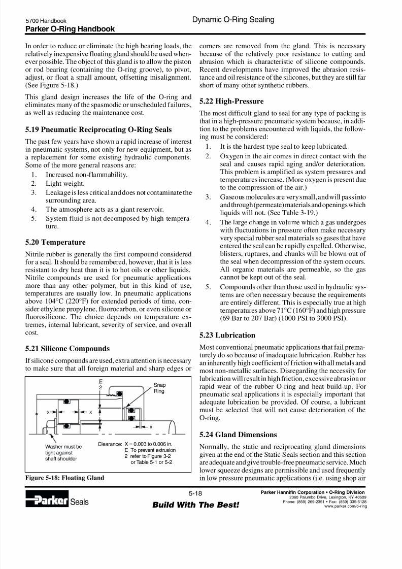
In order to reduce or eliminate the high bearing loads, therelatively inexpensive floating gland should be used when-ever possible. The object of this gland is to allow the pistonor rod bearing (containing the O-ring groove), to pivot,adjust, or float a small amount, offsetting misalignment.(See Figure 5-18.)
This gland design increases the life of the O-ring andeliminates many of the spasmodic or unscheduled failures,as well as reducing the maintenance cost.
5.19 Pneumatic Reciprocating O-Ring Seals
The past few years have shown a rapid increase of interestin pneumatic systems, not only for new equipment, but asa replacement for some existing hydraulic components.Some of the more general reasons are:
1. Increased non-flammability.
2. Light weight.
3. Leakage is less critical and does not contaminate the
surrounding area.4. The atmosphere acts as a giant reservoir.
5. System fluid is not decomposed by high tempera-ture.
5.20 Temperature
Nitrile rubber is generally the first compound consideredfor a seal. It should be remembered, however, that it is lessresistant to dry heat than it is to hot oils or other liquids.Nitrile compounds are used for pneumatic applicationsmore than any other polymer, but in this kind of use,temperatures are usually low. In pneumatic applications
above 104°C (220°F) for extended periods of time, con-sider ethylene propylene, fluorocarbon, or even silicone orfluorosilicone. The choice depends on temperature ex-tremes, internal lubricant, severity of service, and overallcost.
5.21 Silicone Compounds
If silicone compounds are used, extra attention is necessaryto make sure that all foreign material and sharp edges or
corners are removed from the gland. This is necessarybecause of the relatively poor resistance to cutting andabrasion which is characteristic of silicone compounds.Recent developments have improved the abrasion resis-tance and oil resistance of the silicones, but they are still farshort of many other synthetic rubbers.
5.22 High-Pressure
The most difficult gland to seal for any type of packing isthat in a high-pressure pneumatic system because, in addi-tion to the problems encountered with liquids, the follow-ing must be considered:
1. It is the hardest type seal to keep lubricated.
2. Oxygen in the air comes in direct contact with theseal and causes rapid aging and/or deterioration.This problem is amplified as system pressures andtemperatures increase. (More oxygen is present dueto the compression of the air.)
3. Gaseous molecules are very small, and will pass intoand through (permeate) materials and openings whichliquids will not. (See Table 3-19.)
4. The large change in volume which a gas undergoeswith fluctuations in pressure often make necessaryvery special rubber seal materials so gases that haveentered the seal can be rapidly expelled. Otherwise,blisters, ruptures, and chunks will be blown out of the seal when decompression of the system occurs.All organic materials are permeable, so the gascannot be kept out of the seal.
5. Compounds other than those used in hydraulic sys-tems are often necessary because the requirementsare entirely different. This is especially true at hightemperatures above 71°C (160°F) and high pressure(69 Bar to 207 Bar) (1000 PSI to 3000 PSI).
5.23 Lubrication
Most conventional pneumatic applications that fail prema-turely do so because of inadequate lubrication. Rubber hasan inherently high coefficient of friction with all metals andmost non-metallic surfaces. Disregarding the necessity forlubrication will result in high friction, excessive abrasion orrapid wear of the rubber O-ring and heat build-up. Forpneumatic seal applications it is especially important thatadequate lubrication be provided. Of course, a lubricantmust be selected that will not cause deterioration of theO-ring.
5.24 Gland Dimensions
Normally, the static and reciprocating gland dimensionsgiven at the end of the Static Seals section and this sectionare adequate and give trouble-free pneumatic service. Muchlower squeeze designs are permissible and used frequentlyin low pressure pneumatic applications (i.e. using shop airFigure 5-18: Floating Gland
Washer must betight againstshaft shoulder
E2 Snap
Ring
Clearance: X = 0.003 to 0.006 in.To prevent extrusion
2 refer to Figure 3-2or Table 5-1 or 5-2
E
X X
X

8/6/2019 Dynamic Oring Sealing
http://slidepdf.com/reader/full/dynamic-oring-sealing 19/49
Parker O-Ring Handbook 5700 Handbook Dynamic O-Ring Sealing
5-19
Build With The Best! Seals
Parker Hannifin Corporation • O-Ring Division
2360 Palumbo Drive, Lexington, KY 4050Phone: (859) 269-2351 • Fax : (859) 335-512www.parker.com/o-rin
pressure for machine tools, holding devices, and similarapplications.)
Since the temperature range is very moderate and a littleleakage is not critical, some liberties can be taken with softmetals, surface finish and other design criteria withoutseriously reducing the life expectancy of this type of seal
(low pressure cases). In fact, successful designs are inservice which vary between the relatively high-squeezehydraulic gland recommendations and the no-squeeze float-ing seal design discussed below. Each application seems tohave an optimum design depending on what is desired.
5.25 Floating Seal
It has been found possible to modify the standard glanddesign for moving seals and reduce breakout friction asmuch as 60%. By allowing the O-ring to float, the frictionalforces are greatly reduced and longer life can be expectedfrom the seal. (See Figure 5-19.) There is a slight increase
in leakage at the beginning of a stroke which for mostpneumatic applications is undetectable. Because of thisleakage and other considerations, the design is recom-mended for a temperature range from -23°C to 82°C (-10°Fto 180°F) and for low pressure (up to 13.8 Bar (200 PSI)) airservice only.
Recommended dimensions for floating pneumatic pistonseal glands are tabulated in Design Chart 5-3 and DesignTable 5-3 at the end of this section. The “floating” featureof this design is the virtual lack of squeeze on the O-ringcross-section. Sealing is accomplished by the peripheralsqueeze applied to the outside diameter of the O-ring as itis assembled into the bore, and air pressure moving the ringinto facial contact with the wall of the groove.
When this principle is understood, it will be seen that whenthe direction of pressurized air is reversed, a puff of airescapes between the inside diameter of the O-ring and thebottom of the groove during the small fraction of a secondit takes the O-ring to move to the other side of the gland.This is the primary reason for the slight increase in leakagementioned for this design.
The floating seal will not trap pressure between two O-ringsin separate grooves unless considerable rubber swell isencountered.
Five or six O-rings are used in adjoining floating seaglands. This design has been used for some hot water andsteam applications as a method of increasing O-ring lifeThe full effect of the hot steam is brought to bear on theinner rings and a lesser amount on the outer rings. Conse-quently, the seal is effective long after a single O-ringwould have failed.
For the design of pneumatic reciprocating rod seals, useDesign Chart 5-2 and Design Table 5-2. This is the crosssection squeeze design used for hydraulic piston and rodseals. Floating seals are not recommended for pneumaticrods, as they would require stretching the O-ring, causingearly aging. Furthermore, since pneumatically actuatedshafts often move rapidly, a stretched O-ring in this situa-tion would be subject to the Gow-Joule effect described inthe rotary seal discussion. For static pneumatic seal de-signs, use Design Chart 4-1 and Design Table 4-1.
5.26 Uni-Directional Gland
This design modification utilizes a uni-directional floatingseal groove and more than one O-ring (see Figure 5-20)The addition of drilled holes in the grooves causes eachO-ring to seal in one direction only, preventing a pressuretrap of non-compressible liquid between the O-rings. Whenusing this design, the gland dimensions given in DesignTable 5-3 are suggested and the holes should be drilled intothe pressure side of the outside grooves on the piston and theinside of the rod glands. As many individual seals asrequired may be used as long as each groove is vented. TheO-rings on either end, alternately seal and release trappedpressure. The three piston O-rings and the two rod O-rings
are never all sealing at the same time. The vents are notnecessary in pneumatic designs.
5.27 Rotary Seal
An O-ring has proved to be a practical rotary shaft seal inmany applications. With the correct design, Parker O-Ringrotary seal compound N1090-85, will provide satisfactoryservice at surface speeds up to 1500 feet per minute. Thiscompound should not be used in contact with stainless steebecause the graphite it contains may cause pitting on themetal surfaces.
Figure 5-20: Use of Multiple O-Rings in a Floating O-Ring
DesignFigure 5-19: Floating O-Ring Seal
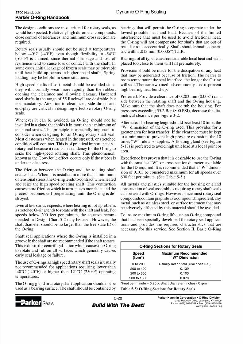
8/6/2019 Dynamic Oring Sealing
http://slidepdf.com/reader/full/dynamic-oring-sealing 20/49
Parker O-Ring Handbook 5700 Handbook Dynamic O-Ring Sealing
5-20
Build With The Best! Seals
Parker Hannifin Corporation • O-Ring Division
2360 Palumbo Drive, Lexington, KY 40509Phone: (859) 269-2351 • Fax : (859) 335-5128www.parker.com/o-ring
The design conditions are most critical for rotary seals, aswould be expected. Relatively high durometer compounds,close control of tolerances, and minimum cross section arerequired.
Rotary seals usually should not be used at temperaturesbelow -40°C (-40°F) even though flexibility to -54°C
(-65°F) is claimed, since thermal shrinkage and loss of resilience tend to cause loss of contact with the shaft. Insome cases, initial leakage of frozen seals may be tolerableuntil heat build-up occurs in higher speed shafts. Springloading may be helpful in some situations.
High-speed shafts of soft metal should be avoided sincethey will normally wear more rapidly than the rubber,opening the clearance and allowing leakage. Hardenedsteel shafts in the range of 55 Rockwell are desirable, butnot mandatory. Attention to clearances, side thrust, andend-play are critical in designing effective rotary O-ringseals.
Whenever it can be avoided, an O-ring should not beinstalled in a gland that holds it in more than a minimum of tensional stress. This principle is especially important toconsider when designing for an O-ring rotary shaft seal.Most elastomers when heated in the stressed, or stretchedcondition will contract. This is of practical importance in arotary seal because it results in a tendency for the O-ring toseize the high-speed rotating shaft. This phenomenon,known as the Gow-Joule effect, occurs only if the rubber isunder tensile stress.
The friction between the O-ring and the rotating shaftcreates heat. When it is installed in more than a minimum
of tensional stress, the O-ring tends to contract when heatedand seize the high speed rotating shaft. This contractioncauses more friction which in turn causes more heat and theprocess becomes self-perpetuating, until the O-ring is de-stroyed.
Even at low surface speeds, where heating is not a problem,a stretched O-ring tends to rotate with the shaft and leak. Forspeeds below 200 feet per minute, the squeeze recom-mended in Design Chart 5-2 may be used. However, theshaft diameter should be no larger than the free state ID of the O-ring.
Shaft seal applications where the O-ring is installed in a
groove in the shaft are not recommended if the shaft rotates.This is due to the centrifugal action which causes the O-ringto rotate and rub on all surfaces which generally causesearly seal leakage or failure.
The use of O-rings as high speed rotary shaft seals is usuallynot recommended for applications requiring lower than-40°C (-40°F) or higher than 121°C (250°F) operatingtemperatures.
The O-ring gland in a rotary shaft application should not beused as a bearing surface. The shaft should be contained by
bearings that will permit the O-ring to operate under thelowest possible heat and load. Because of the limitedinterference that must be used to avoid frictional heat,the O-ring will not compensate for shafts that are out of round or rotate eccentrically. Shafts should remain concen-tric within .013 mm (0.0005") T.I.R.
Bearings of all types cause considerable local heat and sealsplaced too close to them will fail prematurely.
Provision should be made for the dissipation of any heatthat may be generated because of friction. The nearer toroom temperature the seal interface, the longer the O-ringwill seal. There are two methods commonly used to preventhigh bearing heat build-up:
Preferred: Provide a clearance of 0.203 mm (0.008") on aside between the rotating shaft and the O-ring housing.Make sure that the shaft does not rub the housing. Forpressures exceeding 55.2 Bar (800 PSI), decrease the dia-metrical clearance per Figure 3-2.
Alternate: The bearing length should be at least 10 times the“W” dimension of the O-ring used. This provides for agreater area for heat transfer. If the clearance must be keptto a minimum to prevent high pressure extrusion, the 10times “W” rule also applies. A floating gland (see Figure5-18) is preferred to avoid high unit load at a local point orarea.
Experience has proven that it is desirable to use the O-ringwith the smallest “W”, or cross-section diameter, availablefor the ID required. It is recommended that a “W” dimen-sion of 0.103 be considered maximum for all speeds over600 feet per minute. (See Table 5-5.)
All metals and plastics suitable for the housing or glandconstruction of seal assemblies requiring rotary shaft sealscan be used with O-rings. However, since most rotary sealcompounds contain graphite as a compound ingredient, anymetal, such as stainless steel, or surface treatment that maybe adversely affected by this material should be avoided.
To insure maximum O-ring life, use an O-ring compoundthat has been specially developed for rotary seal applica-tions and provides the required characteristics that arenecessary for this service. See Section II, Basic O-Ring
O-Ring Sections for Rotary Seals
Speed Maximum Recommended(fpm*) “W” Dimension
0 to 200 Usually not critical (Use chart 5-2)
200 to 400 0.139
200 to 600 0.103
200 to 1500 0.070
*Feet per minute = 0.26 X Shaft Diameter (inches) X rpm
Table 5-5: O-Ring Sections for Rotary Seals

8/6/2019 Dynamic Oring Sealing
http://slidepdf.com/reader/full/dynamic-oring-sealing 21/49
Parker O-Ring Handbook 5700 Handbook Dynamic O-Ring Sealing
5-21
Build With The Best! Seals
Parker Hannifin Corporation • O-Ring Division
2360 Palumbo Drive, Lexington, KY 4050Phone: (859) 269-2351 • Fax : (859) 335-512www.parker.com/o-rin
Elastomers, for more information on rotary seal com-pounds.
Figure 5-21 shows two methods of “spring loading” thehard rotary seal. Either of these should only be used whenabsolutely necessary to obtain the desired seal.
See Table 5-6 for a rotary seal design example.
5.28 Oscillating Seal
In this guide, two types of oscillating seals are considered:
1. Faucet or valve stems are excellent examples of assemblies that can be simplified by the use of anO-ring seal. Compression type or multiple-lip pack-ing can be eliminated, reducing space requirements
Figure 5-21: Spring-Loading for Rotary Seal
Soft Rubber Ring
Rotary Seal O-Ring 80 Durometer
Soft O-Ring
and eliminating the need for adjusting or take-updevices. For applications of this type, if the speed isunder 200 feet per minute, use Design Table 5-2 forselecting O-ring sizes and gland dimensions.
2. Constantly oscillating shafts, such as those used ontiming and metering devices, can be sealed satisfac-torily with O-rings. If the motion is continuous forlong periods of time, use Design Table 5-4 forO-ring sizes and gland dimensions.
5.29 Seat Seals
A properly designed check or poppet type valve, with anO-ring on the seat, will give an exceptionally long, non-leaking service. Many designers and engineers make thecostly mistake of trying to use a conventional groove(square or rectangular) design to hold the O-ring.
With this type of groove, “blow-out’’ will normally occurwhen the valve is unseated.
“Blow-out” is a type of seal failure caused by the action ofthe pressure in the system on the side of the O-ring, forcingit out of the groove into some other part of the valve orsystem. “Blow-out” usually occurs at differential pressuresabove 5.5 Bar (80 PSI). The exact pressure will depend onthe gas or fluid, valve design and the physical properties of
Problem: To design a rotary seal gland for a 76.2 mm (3") (desired) shaft running at 1750 RPM with oil pressureat 6.9 Bar (100 PSI).
Procedural Steps:
(A) Calculate surface speed.
(B) Determine O-ring cross section that may be usedfrom Table 5-5.
(C) Select .070 cross section O-ring with actual IDclosest to desired shaft OD from Design Table 5-4.
(D) Add 0.002 to O-ring ID to determine max. actualshaft OD, B.
(E) Determine gland depth, L from Design Chart 5-4.
(F) Calculate Gland Groove ID, A-1A-1 min = B max. + 2L min.A-1 max. = B min. + 2L max.
(G) Determine diametral clearance, E from Design Chart5-4.
(H) Calculate shaft bore DD min. = B max. + E min.D max. = B min. + E max.
(I) Determine groove width, G from Design Chart 5-4.
(J) Check Figure 3-2 to make sure design is extrusionsafe.
Example:
(A) Speed = 0.26 X 3 X 1750 = 1365 fpm
(B) .070 (larger cross sections are eliminateddue to speed)
(C) Parker No. 2-041
(D) B max. = 2.969 + 0.002 = 2.991(TOL: + .000, - .001)
(E) 0.065 to 0.067
(F)A-1 min. = 2.991 + 2(0.065) = 3.121A-1 max. = 2.990 + (0.067) = 3.124
A-1 = 3.121 (TOL: + .003, - .000)(G) 0.012 + 0.016
(H)D min. = 2.991 + 0.012 = 3.003D max. = 2.990 + 0.016 = 3.006D = 3.003 (TOL: + .003, -.000)
(I) 0.075 - 0.079
Table 5-6: Rotary Seal Design Example
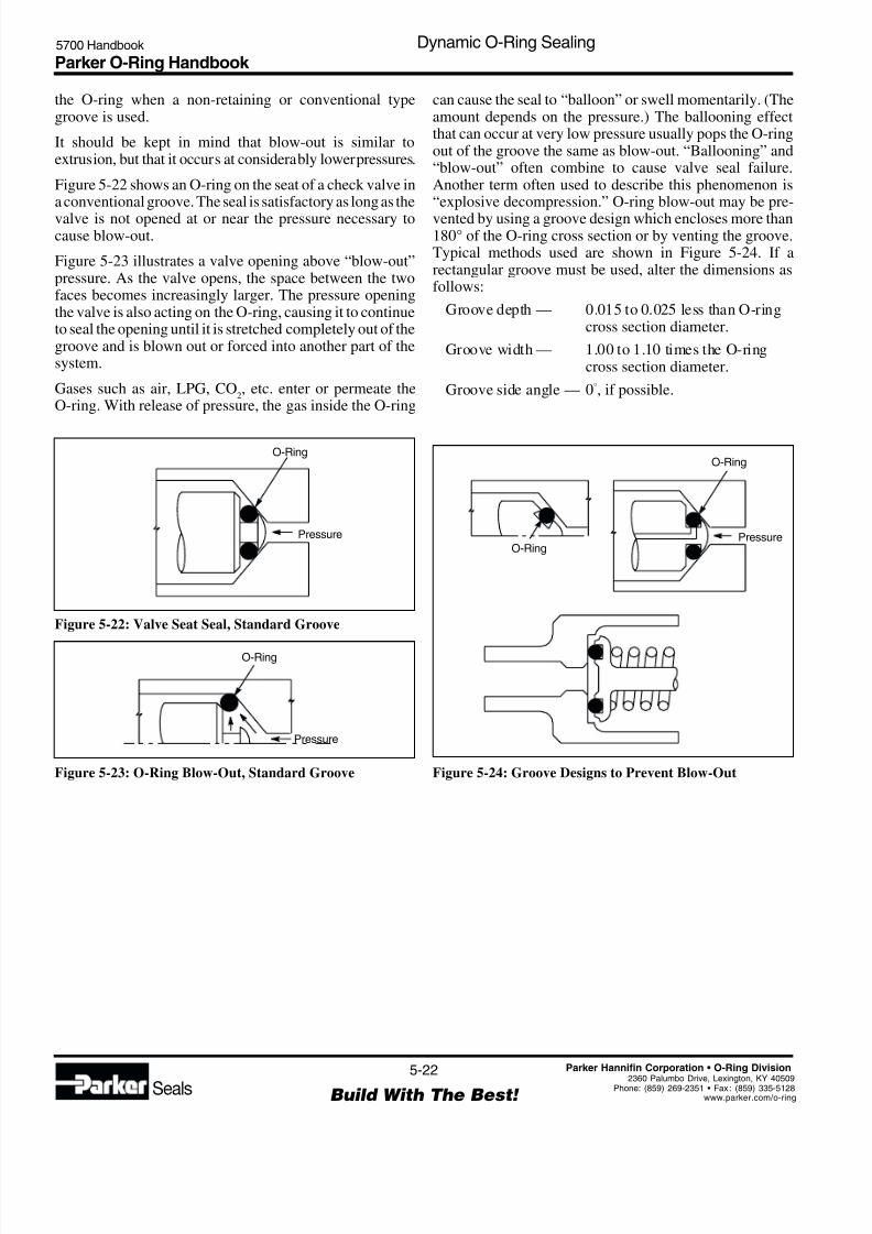
8/6/2019 Dynamic Oring Sealing
http://slidepdf.com/reader/full/dynamic-oring-sealing 22/49
Parker O-Ring Handbook 5700 Handbook Dynamic O-Ring Sealing
5-22
Build With The Best! Seals
Parker Hannifin Corporation • O-Ring Division
2360 Palumbo Drive, Lexington, KY 40509Phone: (859) 269-2351 • Fax : (859) 335-5128www.parker.com/o-ring
Figure 5-24: Groove Designs to Prevent Blow-Out
O-Ring
O-Ring
Pressure
the O-ring when a non-retaining or conventional typegroove is used.
It should be kept in mind that blow-out is similar toextrusion, but that it occurs at considerably lower pressures.
Figure 5-22 shows an O-ring on the seat of a check valve ina conventional groove. The seal is satisfactory as long as the
valve is not opened at or near the pressure necessary tocause blow-out.
Figure 5-23 illustrates a valve opening above “blow-out”pressure. As the valve opens, the space between the twofaces becomes increasingly larger. The pressure openingthe valve is also acting on the O-ring, causing it to continueto seal the opening until it is stretched completely out of thegroove and is blown out or forced into another part of thesystem.
Gases such as air, LPG, CO2, etc. enter or permeate the
O-ring. With release of pressure, the gas inside the O-ring
Figure 5-22: Valve Seat Seal, Standard Groove
O-Ring
Pressure
O-Ring
Pressure
Figure 5-23: O-Ring Blow-Out, Standard Groove
can cause the seal to “balloon” or swell momentarily. (Theamount depends on the pressure.) The ballooning effectthat can occur at very low pressure usually pops the O-ringout of the groove the same as blow-out. “Ballooning” and“blow-out” often combine to cause valve seal failure.Another term often used to describe this phenomenon is“explosive decompression.” O-ring blow-out may be pre-
vented by using a groove design which encloses more than180° of the O-ring cross section or by venting the groove.Typical methods used are shown in Figure 5-24. If arectangular groove must be used, alter the dimensions asfollows:
Groove depth — 0.015 to 0.025 less than O-ringcross section diameter.
Groove width — 1.00 to 1.10 times the O-ringcross section diameter.
Groove side angle — 0°, if possible.
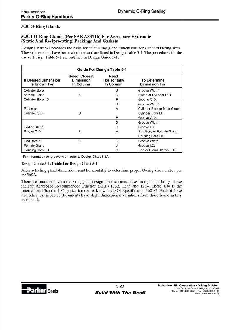
8/6/2019 Dynamic Oring Sealing
http://slidepdf.com/reader/full/dynamic-oring-sealing 23/49
Parker O-Ring Handbook 5700 Handbook Dynamic O-Ring Sealing
5-23
Build With The Best! Seals
Parker Hannifin Corporation • O-Ring Division
2360 Palumbo Drive, Lexington, KY 4050Phone: (859) 269-2351 • Fax : (859) 335-512www.parker.com/o-rin
Guide For Design Table 5-1
Select Closest ReadIf Desired Dimension Dimension Horizontally To Determine
Is Known For In Column In Column Dimension For
Cylinder Bore G Groove Width*
or Male Gland A C Piston or Cylinder O.D.
Cylinder Bore I.D F Groove O.D.
G Groove Width*
Piston or A Cylinder Bore or Male Gland
Cylinder O.D. C Cylinder Bore I.D.
F Groove O.D.
G Groove Width*
Rod or Gland J Groove I.D.
Sleeve O.D. B H Rod Bore or Female Gland
Housing Bore I.D.
Rod Bore or H G Groove Width*
Female Gland J Groove I.D.
Housing Bore I.D. B Rod or Gland Sleeve O.D.
*For information on groove width refer to Design Chart 5-1A
Design Guide 5-1: Guide For Design Chart 5-1
After selecting gland dimension, read horizontally to determine proper O-ring size number per
AS568A.
There are a number of various O-ring gland design specifications in use throughout industry. Theseinclude Aerospace Recommended Practice (ARP) 1232, 1233 and 1234. There also is theInternational Standards Organization (better known as ISO) Specification 3601/2. Each of theseand other less accepted documents have slight dimensional variations from those found in thisHandbook.
5.30 O-Ring Glands
5.30.1 O-Ring Glands (Per SAE AS4716) For Aerospace Hydraulic(Static And Reciprocating) Packings And Gaskets
Design Chart 5-1 provides the basis for calculating gland dimensions for standard O-ring sizes.These dimensions have been calculated and are listed in Design Table 5-1. The procedures for the
use of Design Table 5-1 are outlined in Design Guide 5-1.
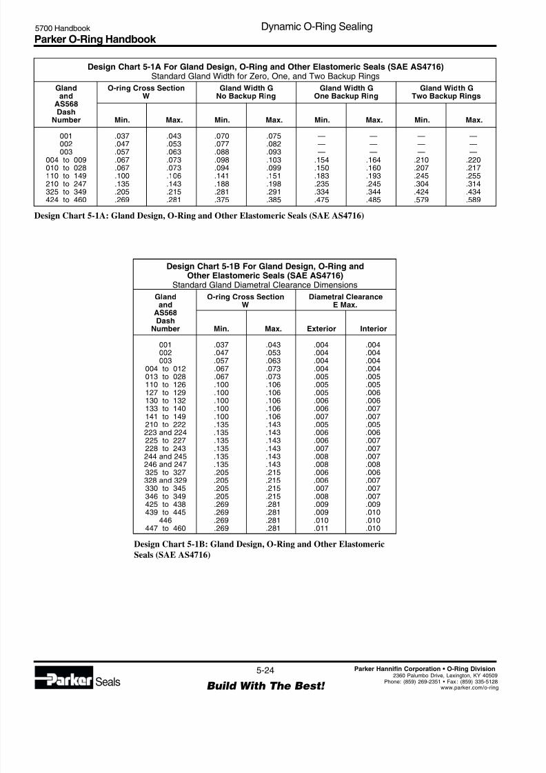
8/6/2019 Dynamic Oring Sealing
http://slidepdf.com/reader/full/dynamic-oring-sealing 24/49
Parker O-Ring Handbook 5700 Handbook Dynamic O-Ring Sealing
5-24
Build With The Best! Seals
Parker Hannifin Corporation • O-Ring Division
2360 Palumbo Drive, Lexington, KY 40509Phone: (859) 269-2351 • Fax : (859) 335-5128www.parker.com/o-ring
Design Chart 5-1A For Gland Design, O-Ring and Other Elastomeric Seals (SAE AS4716)Standard Gland Width for Zero, One, and Two Backup Rings
Gland O-ring Cross Section Gland Width G Gland Width G Gland Width Gand W No Backup Ring One Backup Ring Two Backup Rings
AS568Dash
Number Min. Max. Min. Max. Min. Max. Min. Max.
001 .037 .043 .070 .075 — — — —002 .047 .053 .077 .082 — — — —003 .057 .063 .088 .093 — — — —
004 to 009 .067 .073 .098 .103 .154 .164 .210 .220010 to 028 .067 .073 .094 .099 .150 .160 .207 .217110 to 149 .100 .106 .141 .151 .183 .193 .245 .255210 to 247 .135 .143 .188 .198 .235 .245 .304 .314325 to 349 .205 .215 .281 .291 .334 .344 .424 .434424 to 460 .269 .281 .375 .385 .475 .485 .579 .589
Design Chart 5-1A: Gland Design, O-Ring and Other Elastomeric Seals (SAE AS4716)
Design Chart 5-1B For Gland Design, O-Ring andOther Elastomeric Seals (SAE AS4716)Standard Gland Diametral Clearance Dimensions
Gland O-ring Cross Section Diametral Clearanceand W E Max.
AS568Dash
Number Min. Max. Exterior Interior
001 .037 .043 .004 .004002 .047 .053 .004 .004003 .057 .063 .004 .004
004 to 012 .067 .073 .004 .004013 to 028 .067 .073 .005 .005110 to 126 .100 .106 .005 .005127 to 129 .100 .106 .005 .006130 to 132 .100 .106 .006 .006133 to 140 .100 .106 .006 .007141 to 149 .100 .106 .007 .007210 to 222 .135 .143 .005 .005223 and 224 .135 .143 .006 .006225 to 227 .135 .143 .006 .007228 to 243 .135 .143 .007 .007244 and 245 .135 .143 .008 .007246 and 247 .135 .143 .008 .008325 to 327 .205 .215 .006 .006328 and 329 .205 .215 .006 .007330 to 345 .205 .215 .007 .007346 to 349 .205 .215 .008 .007425 to 438 .269 .281 .009 .009439 to 445 .269 .281 .009 .010
446 .269 .281 .010 .010447 to 460 .269 .281 .011 .010
Design Chart 5-1B: Gland Design, O-Ring and Other ElastomericSeals (SAE AS4716)
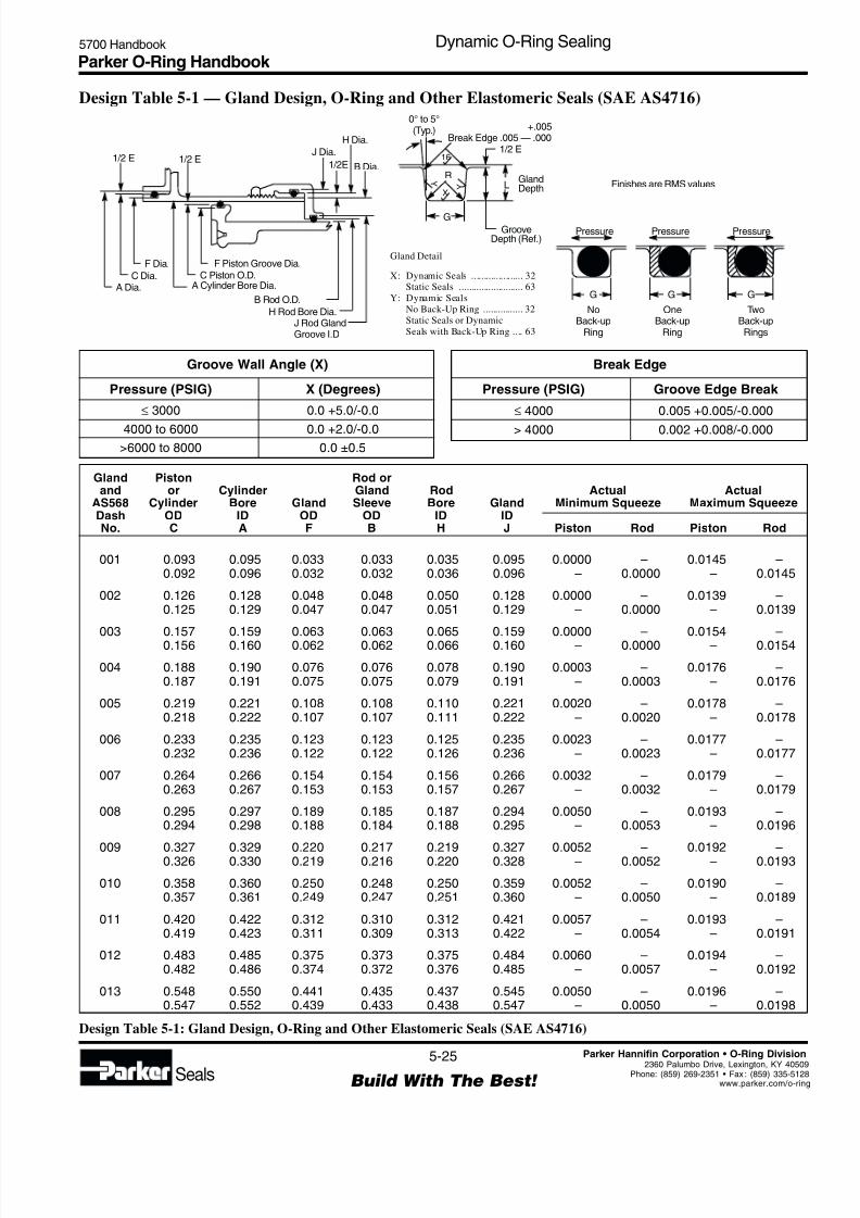
8/6/2019 Dynamic Oring Sealing
http://slidepdf.com/reader/full/dynamic-oring-sealing 25/49
Parker O-Ring Handbook 5700 Handbook Dynamic O-Ring Sealing
5-25
Build With The Best! Seals
Parker Hannifin Corporation • O-Ring Division
2360 Palumbo Drive, Lexington, KY 4050Phone: (859) 269-2351 • Fax : (859) 335-512www.parker.com/o-rin
Gland Detail
X: Dynamic Seals ..................... 32Static Seals .......................... 63
Y: Dynamic Seals
No Back-Up Ring ................ 32
Static Seals or Dynamic
Seals with Back-Up Ring .... 63
1/2 E 1/2 E1/2E
H Dia.
J Dia.
F Dia.
C Dia.A Dia.
F Piston Groove Dia.C Piston O.D.
A Cylinder Bore Dia.
B Rod O.D.
H Rod Bore Dia.
1/2 E
L
G
R
16
Y
XY
0° to 5°(Typ.) +.005
Break Edge .005 — .000
J Rod GlandGroove I.D
NoBack-up
Ring
OneBack-up
Ring
Pressure Pressure Pressure
TwoBack-upRings
GG G
B Dia.
Finishes are RMS valuesGlandDepth
GrooveDepth (Ref.)
Design Table 5-1 — Gland Design, O-Ring and Other Elastomeric Seals (SAE AS4716)
Groove Wall Angle (X)
Pressure (PSIG) X (Degrees)
≤ 3000 0.0 +5.0/-0.0
4000 to 6000 0.0 +2.0/-0.0
>6000 to 8000 0.0 ±0.5
Break Edge
Pressure (PSIG) Groove Edge Break
≤ 4000 0.005 +0.005/-0.000
> 4000 0.002 +0.008/-0.000
Gland Piston Rod orand or Cylinder Gland Rod Actual Actual
AS568 Cylinder Bore Gland Sleeve Bore Gland Minimum Squeeze Maximum SqueezeDash OD ID OD OD ID IDNo. C A F B H J Piston Rod Piston Rod
Design Table 5-1: Gland Design, O-Ring and Other Elastomeric Seals (SAE AS4716)
001 0.093 0.095 0.033 0.033 0.035 0.095 0.0000 – 0.0145 –0.092 0.096 0.032 0.032 0.036 0.096 – 0.0000 – 0.0145
002 0.126 0.128 0.048 0.048 0.050 0.128 0.0000 – 0.0139 –0.125 0.129 0.047 0.047 0.051 0.129 – 0.0000 – 0.0139
003 0.157 0.159 0.063 0.063 0.065 0.159 0.0000 – 0.0154 –0.156 0.160 0.062 0.062 0.066 0.160 – 0.0000 – 0.0154
004 0.188 0.190 0.076 0.076 0.078 0.190 0.0003 – 0.0176 –0.187 0.191 0.075 0.075 0.079 0.191 – 0.0003 – 0.0176
005 0.219 0.221 0.108 0.108 0.110 0.221 0.0020 – 0.0178 –0.218 0.222 0.107 0.107 0.111 0.222 – 0.0020 – 0.0178
006 0.233 0.235 0.123 0.123 0.125 0.235 0.0023 – 0.0177 –0.232 0.236 0.122 0.122 0.126 0.236 – 0.0023 – 0.0177
007 0.264 0.266 0.154 0.154 0.156 0.266 0.0032 – 0.0179 –0.263 0.267 0.153 0.153 0.157 0.267 – 0.0032 – 0.0179
008 0.295 0.297 0.189 0.185 0.187 0.294 0.0050 – 0.0193 –0.294 0.298 0.188 0.184 0.188 0.295 – 0.0053 – 0.0196
009 0.327 0.329 0.220 0.217 0.219 0.327 0.0052 – 0.0192 –0.326 0.330 0.219 0.216 0.220 0.328 – 0.0052 – 0.0193
010 0.358 0.360 0.250 0.248 0.250 0.359 0.0052 – 0.0190 –0.357 0.361 0.249 0.247 0.251 0.360 – 0.0050 – 0.0189
011 0.420 0.422 0.312 0.310 0.312 0.421 0.0057 – 0.0193 –0.419 0.423 0.311 0.309 0.313 0.422 – 0.0054 – 0.0191
012 0.483 0.485 0.375 0.373 0.375 0.484 0.0060 – 0.0194 –0.482 0.486 0.374 0.372 0.376 0.485 – 0.0057 – 0.0192
013 0.548 0.550 0.441 0.435 0.437 0.545 0.0050 – 0.0196 –0.547 0.552 0.439 0.433 0.438 0.547 – 0.0050 – 0.0198
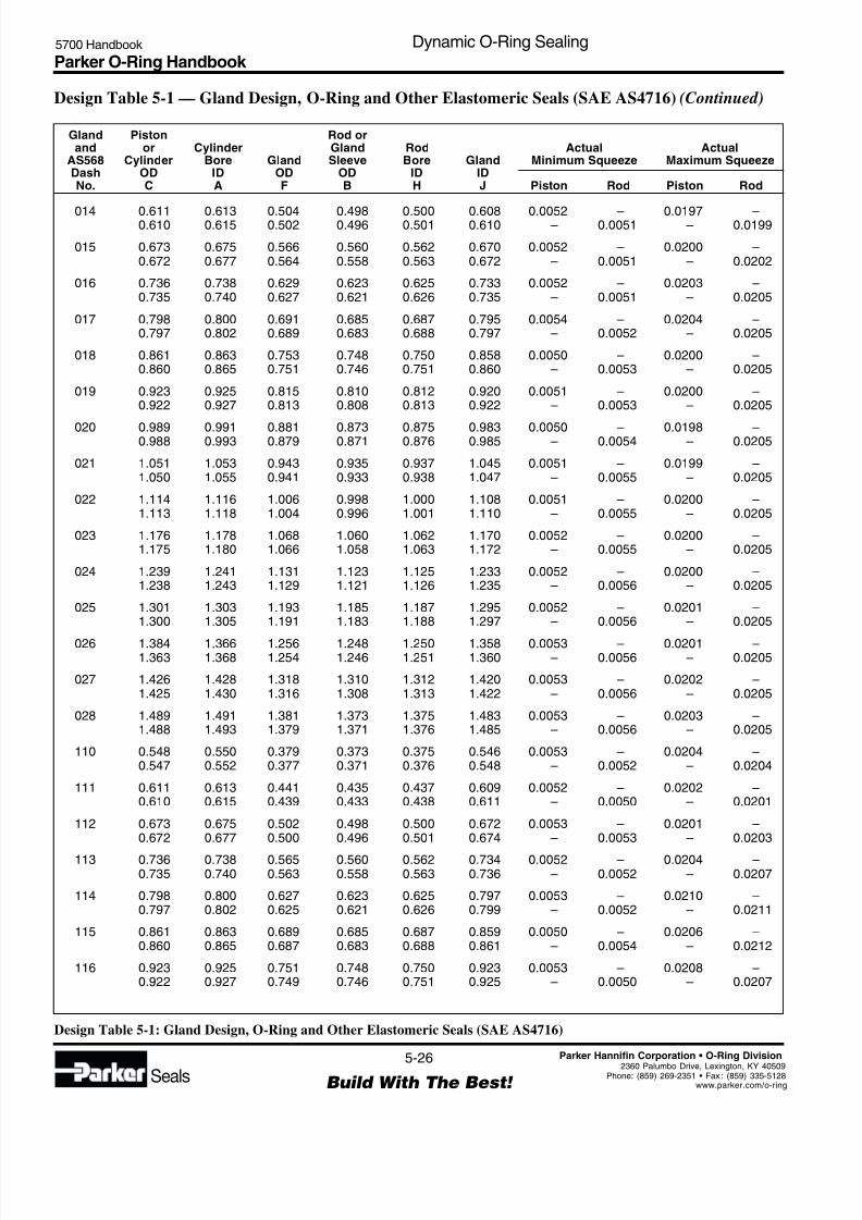
8/6/2019 Dynamic Oring Sealing
http://slidepdf.com/reader/full/dynamic-oring-sealing 26/49
Parker O-Ring Handbook 5700 Handbook Dynamic O-Ring Sealing
5-26
Build With The Best! Seals
Parker Hannifin Corporation • O-Ring Division
2360 Palumbo Drive, Lexington, KY 40509Phone: (859) 269-2351 • Fax : (859) 335-5128www.parker.com/o-ring
Gland Piston Rod orand or Cylinder Gland Rod Actual Actual
AS568 Cylinder Bore Gland Sleeve Bore Gland Minimum Squeeze Maximum SqueezeDash OD ID OD OD ID IDNo. C A F B H J Piston Rod Piston Rod
Design Table 5-1 — Gland Design, O-Ring and Other Elastomeric Seals (SAE AS4716) (Continued)
Design Table 5-1: Gland Design, O-Ring and Other Elastomeric Seals (SAE AS4716)
014 0.611 0.613 0.504 0.498 0.500 0.608 0.0052 – 0.0197 –0.610 0.615 0.502 0.496 0.501 0.610 – 0.0051 – 0.0199
015 0.673 0.675 0.566 0.560 0.562 0.670 0.0052 – 0.0200 –0.672 0.677 0.564 0.558 0.563 0.672 – 0.0051 – 0.0202
016 0.736 0.738 0.629 0.623 0.625 0.733 0.0052 – 0.0203 –0.735 0.740 0.627 0.621 0.626 0.735 – 0.0051 – 0.0205
017 0.798 0.800 0.691 0.685 0.687 0.795 0.0054 – 0.0204 –0.797 0.802 0.689 0.683 0.688 0.797 – 0.0052 – 0.0205
018 0.861 0.863 0.753 0.748 0.750 0.858 0.0050 – 0.0200 –0.860 0.865 0.751 0.746 0.751 0.860 – 0.0053 – 0.0205
019 0.923 0.925 0.815 0.810 0.812 0.920 0.0051 – 0.0200 –0.922 0.927 0.813 0.808 0.813 0.922 – 0.0053 – 0.0205
020 0.989 0.991 0.881 0.873 0.875 0.983 0.0050 – 0.0198 –0.988 0.993 0.879 0.871 0.876 0.985 – 0.0054 – 0.0205
021 1.051 1.053 0.943 0.935 0.937 1.045 0.0051 – 0.0199 –1.050 1.055 0.941 0.933 0.938 1.047 – 0.0055 – 0.0205
022 1.114 1.116 1.006 0.998 1.000 1.108 0.0051 – 0.0200 –1.113 1.118 1.004 0.996 1.001 1.110 – 0.0055 – 0.0205
023 1.176 1.178 1.068 1.060 1.062 1.170 0.0052 – 0.0200 –1.175 1.180 1.066 1.058 1.063 1.172 – 0.0055 – 0.0205
024 1.239 1.241 1.131 1.123 1.125 1.233 0.0052 – 0.0200 –1.238 1.243 1.129 1.121 1.126 1.235 – 0.0056 – 0.0205
025 1.301 1.303 1.193 1.185 1.187 1.295 0.0052 – 0.0201 –1.300 1.305 1.191 1.183 1.188 1.297 – 0.0056 – 0.0205
026 1.384 1.366 1.256 1.248 1.250 1.358 0.0053 – 0.0201 –1.363 1.368 1.254 1.246 1.251 1.360 – 0.0056 – 0.0205
027 1.426 1.428 1.318 1.310 1.312 1.420 0.0053 – 0.0202 –1.425 1.430 1.316 1.308 1.313 1.422 – 0.0056 – 0.0205
028 1.489 1.491 1.381 1.373 1.375 1.483 0.0053 – 0.0203 –1.488 1.493 1.379 1.371 1.376 1.485 – 0.0056 – 0.0205
110 0.548 0.550 0.379 0.373 0.375 0.546 0.0053 – 0.0204 –0.547 0.552 0.377 0.371 0.376 0.548 – 0.0052 – 0.0204
111 0.611 0.613 0.441 0.435 0.437 0.609 0.0052 – 0.0202 –0.610 0.615 0.439 0.433 0.438 0.611 – 0.0050 – 0.0201
112 0.673 0.675 0.502 0.498 0.500 0.672 0.0053 – 0.0201 –0.672 0.677 0.500 0.496 0.501 0.674 – 0.0053 – 0.0203
113 0.736 0.738 0.565 0.560 0.562 0.734 0.0052 – 0.0204 –0.735 0.740 0.563 0.558 0.563 0.736 – 0.0052 – 0.0207
114 0.798 0.800 0.627 0.623 0.625 0.797 0.0053 – 0.0210 –0.797 0.802 0.625 0.621 0.626 0.799 – 0.0052 – 0.0211
115 0.861 0.863 0.689 0.685 0.687 0.859 0.0050 – 0.0206 –0.860 0.865 0.687 0.683 0.688 0.861 – 0.0054 – 0.0212
116 0.923 0.925 0.751 0.748 0.750 0.923 0.0053 – 0.0208 –0.922 0.927 0.749 0.746 0.751 0.925 – 0.0050 – 0.0207
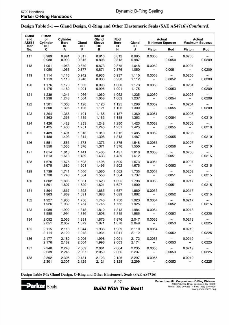
8/6/2019 Dynamic Oring Sealing
http://slidepdf.com/reader/full/dynamic-oring-sealing 27/49
Parker O-Ring Handbook 5700 Handbook Dynamic O-Ring Sealing
5-27
Build With The Best! Seals
Parker Hannifin Corporation • O-Ring Division
2360 Palumbo Drive, Lexington, KY 4050Phone: (859) 269-2351 • Fax : (859) 335-512www.parker.com/o-rin
Gland Piston Rod orand or Cylinder Gland Rod Actual Actual
AS568 Cylinder Bore Gland Sleeve Bore Gland Minimum Squeeze Maximum SqueezeDash OD ID OD OD ID IDNo. C A F B H J Piston Rod Piston Rod
Design Table 5-1: Gland Design, O-Ring and Other Elastomeric Seals (SAE AS4716)
117 0.989 0.991 0.817 0.810 0.812 0.985 0.0050 – 0.0205 –0.988 0.993 0.815 0.808 0.813 0.987 – 0.0050 – 0.0209
118 1.051 1.053 0.879 0.873 0.875 1.048 0.0052 – 0.0207 –1.050 1.055 0.877 0.871 0.876 1.050 – 0.0051 – 0.0209
119 1.114 1.116 0.942 0.935 0.937 1.110 0.0053 – 0.0206 –1.113 1.118 0.940 0.933 0.938 1.112 – 0.0052 – 0.0209
120 1.176 1.178 1.003 0.998 1.000 1.173 0.0050 – 0.0204 –1.175 1.180 1.001 0.996 1.001 1.175 – 0.0053 – 0.0209
121 1.239 1.241 1.066 1.060 1.062 1.235 0.0050 – 0.0203 –1.238 1.243 1.064 1.058 1.063 1.237 – 0.0054 – 0.0209
122 1.301 1.303 1.128 1.123 1.125 1.298 0.0052 – 0.0204 –1.300 1.305 1.126 1.121 1.126 1.300 – 0.0055 – 0.0209
123 1.364 1.366 1.191 1.185 1.187 1.360 0.0051 – 0.0205 –1.363 1.368 1.189 1.183 1.188 1.362 – 0.0054 – 0.0210
124 1.426 1.428 1.253 1.248 1.250 1.423 0.0052 – 0.0206 –1.425 1.430 1.251 1.246 1.251 1.425 – 0.0055 – 0.0210
125 1.489 1.491 1.316 1.310 1.312 1.485 0.0052 – 0.0206 –1.488 1.493 1.314 1.308 1.313 1.487 – 0.0055 – 0.0210
126 1.551 1.553 1.378 1.373 1.375 1.548 0.0053 – 0.0207 –1.550 1.555 1.376 1.371 1.376 1.550 – 0.0056 – 0.0210
127 1.614 1.616 1.441 1.435 1.437 1.610 0.0053 – 0.0206 –1.613 1.618 1.439 1.433 1.439 1.612 – 0.0051 – 0.0215
128 1.676 1.678 1.503 1.498 1.500 1.673 0.0054 – 0.0207 –1.675 1.680 1.501 1.496 1.502 1.675 – 0.0052 – 0.0215
129 1.739 1.741 1.566 1.560 1.562 1.735 0.0053 – 0.0208 –1.738 1.743 1.564 1.558 1.564 1.737 – 0.0051 – 0.0215
130 1.802 1.805 1.631 1.623 1.625 1.798 0.0053 – 0.0217 –1.801 1.807 1.629 1.621 1.627 1.800 – 0.0051 – 0.0215
131 1.864 1.867 1.693 1.685 1.687 1.860 0.0053 – 0.0217 –1.863 1.869 1.691 1.683 1.689 1.862 – 0.0052 – 0.0215
132 1.927 1.930 1.756 1.748 1.750 1.923 0.0054 – 0.0217 –1.926 1.932 1.754 1.746 1.752 1.925 – 0.0052 – 0.0215
133 1.989 1.992 1.818 1.810 1.813 1.984 0.0054 – 0.0218 –1.988 1.994 1.816 1.808 1.815 1.986 – 0.0052 – 0.0225
134 2.052 2.055 1.881 1.873 1.876 2.047 0.0055 – 0.0218 –2.051 2.057 1.879 1.871 1.878 2.049 – 0.0053 – 0.0225
135 2.115 2.118 1.944 1.936 1.939 2.110 0.0054 – 0.0219 –2.114 2.120 1.942 1.934 1.941 2.112 – 0.0052 – 0.0225
136 2.177 2.180 2.006 1.998 2.001 2.172 0.0055 – 0.0219 –2.176 2.182 2.004 1.996 2.003 2.174 – 0.0053 – 0.0225
137 2.240 2.243 2.069 2.061 2.064 2.235 0.0055 – 0.0219 –2.239 2.245 2.067 2.059 2.066 2.237 – 0.0053 – 0.0225
138 2.302 2.305 2.131 2.123 2.126 2.297 0.0055 – 0.0219 –2.301 2.307 2.129 2.121 2.128 2.299 – 0.0053 – 0.0225
Design Table 5-1 — Gland Design, O-Ring and Other Elastomeric Seals (SAE AS4716) (Continued)
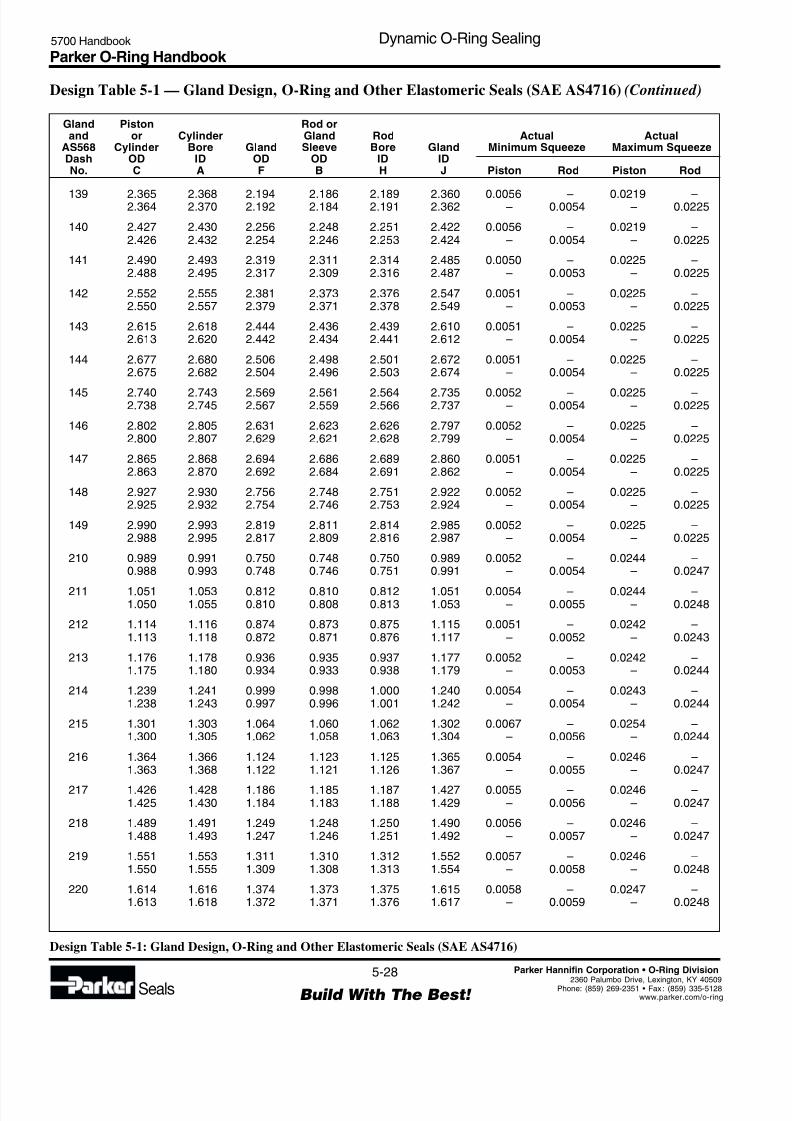
8/6/2019 Dynamic Oring Sealing
http://slidepdf.com/reader/full/dynamic-oring-sealing 28/49
Parker O-Ring Handbook 5700 Handbook Dynamic O-Ring Sealing
5-28
Build With The Best! Seals
Parker Hannifin Corporation • O-Ring Division
2360 Palumbo Drive, Lexington, KY 40509Phone: (859) 269-2351 • Fax : (859) 335-5128www.parker.com/o-ring
Gland Piston Rod orand or Cylinder Gland Rod Actual Actual
AS568 Cylinder Bore Gland Sleeve Bore Gland Minimum Squeeze Maximum SqueezeDash OD ID OD OD ID IDNo. C A F B H J Piston Rod Piston Rod
Design Table 5-1: Gland Design, O-Ring and Other Elastomeric Seals (SAE AS4716)
139 2.365 2.368 2.194 2.186 2.189 2.360 0.0056 – 0.0219 –2.364 2.370 2.192 2.184 2.191 2.362 – 0.0054 – 0.0225
140 2.427 2.430 2.256 2.248 2.251 2.422 0.0056 – 0.0219 –2.426 2.432 2.254 2.246 2.253 2.424 – 0.0054 – 0.0225
141 2.490 2.493 2.319 2.311 2.314 2.485 0.0050 – 0.0225 –2.488 2.495 2.317 2.309 2.316 2.487 – 0.0053 – 0.0225
142 2.552 2.555 2.381 2.373 2.376 2.547 0.0051 – 0.0225 –2.550 2.557 2.379 2.371 2.378 2.549 – 0.0053 – 0.0225
143 2.615 2.618 2.444 2.436 2.439 2.610 0.0051 – 0.0225 –2.613 2.620 2.442 2.434 2.441 2.612 – 0.0054 – 0.0225
144 2.677 2.680 2.506 2.498 2.501 2.672 0.0051 – 0.0225 –2.675 2.682 2.504 2.496 2.503 2.674 – 0.0054 – 0.0225
145 2.740 2.743 2.569 2.561 2.564 2.735 0.0052 – 0.0225 –2.738 2.745 2.567 2.559 2.566 2.737 – 0.0054 – 0.0225
146 2.802 2.805 2.631 2.623 2.626 2.797 0.0052 – 0.0225 –2.800 2.807 2.629 2.621 2.628 2.799 – 0.0054 – 0.0225
147 2.865 2.868 2.694 2.686 2.689 2.860 0.0051 – 0.0225 –2.863 2.870 2.692 2.684 2.691 2.862 – 0.0054 – 0.0225
148 2.927 2.930 2.756 2.748 2.751 2.922 0.0052 – 0.0225 –2.925 2.932 2.754 2.746 2.753 2.924 – 0.0054 – 0.0225
149 2.990 2.993 2.819 2.811 2.814 2.985 0.0052 – 0.0225 –2.988 2.995 2.817 2.809 2.816 2.987 – 0.0054 – 0.0225
210 0.989 0.991 0.750 0.748 0.750 0.989 0.0052 – 0.0244 –0.988 0.993 0.748 0.746 0.751 0.991 – 0.0054 – 0.0247
211 1.051 1.053 0.812 0.810 0.812 1.051 0.0054 – 0.0244 –1.050 1.055 0.810 0.808 0.813 1.053 – 0.0055 – 0.0248
212 1.114 1.116 0.874 0.873 0.875 1.115 0.0051 – 0.0242 –1.113 1.118 0.872 0.871 0.876 1.117 – 0.0052 – 0.0243
213 1.176 1.178 0.936 0.935 0.937 1.177 0.0052 – 0.0242 –1.175 1.180 0.934 0.933 0.938 1.179 – 0.0053 – 0.0244
214 1.239 1.241 0.999 0.998 1.000 1.240 0.0054 – 0.0243 –1.238 1.243 0.997 0.996 1.001 1.242 – 0.0054 – 0.0244
215 1.301 1.303 1.064 1.060 1.062 1.302 0.0067 – 0.0254 –1.300 1.305 1.062 1.058 1.063 1.304 – 0.0056 – 0.0244
216 1.364 1.366 1.124 1.123 1.125 1.365 0.0054 – 0.0246 –1.363 1.368 1.122 1.121 1.126 1.367 – 0.0055 – 0.0247
217 1.426 1.428 1.186 1.185 1.187 1.427 0.0055 – 0.0246 –1.425 1.430 1.184 1.183 1.188 1.429 – 0.0056 – 0.0247
218 1.489 1.491 1.249 1.248 1.250 1.490 0.0056 – 0.0246 –1.488 1.493 1.247 1.246 1.251 1.492 – 0.0057 – 0.0247
219 1.551 1.553 1.311 1.310 1.312 1.552 0.0057 – 0.0246 –1.550 1.555 1.309 1.308 1.313 1.554 – 0.0058 – 0.0248
220 1.614 1.616 1.374 1.373 1.375 1.615 0.0058 – 0.0247 –1.613 1.618 1.372 1.371 1.376 1.617 – 0.0059 – 0.0248
Design Table 5-1 — Gland Design, O-Ring and Other Elastomeric Seals (SAE AS4716) (Continued)

8/6/2019 Dynamic Oring Sealing
http://slidepdf.com/reader/full/dynamic-oring-sealing 29/49
Parker O-Ring Handbook 5700 Handbook Dynamic O-Ring Sealing
5-29
Build With The Best! Seals
Parker Hannifin Corporation • O-Ring Division
2360 Palumbo Drive, Lexington, KY 4050Phone: (859) 269-2351 • Fax : (859) 335-512www.parker.com/o-rin
Gland Piston Rod orand or Cylinder Gland Rod Actual Actual
AS568 Cylinder Bore Gland Sleeve Bore Gland Minimum Squeeze Maximum SqueezeDash OD ID OD OD ID IDNo. C A F B H J Piston Rod Piston Rod
Design Table 5-1: Gland Design, O-Ring and Other Elastomeric Seals (SAE AS4716)
Design Table 5-1 — Gland Design, O-Ring and Other Elastomeric Seals (SAE AS4716) (Continued)
221 1.676 1.678 1.436 1.435 1.437 1.677 0.0059 – 0.0247 –1.675 1.680 1.434 1.433 1.438 1.679 – 0.0059 – 0.0248
222 1.739 1.741 1.499 1.498 1.500 1.740 0.0057 – 0.0250 –1.738 1.743 1.497 1.496 1.501 1.742 – 0.0058 – 0.0250
223 1.864 1.867 1.625 1.623 1.625 1.865 0.0053 – 0.0254 –1.863 1.869 1.623 1.621 1.627 1.867 – 0.0054 – 0.0255
224 1.989 1.992 1.750 1.748 1.750 1.990 0.0055 – 0.0254 –1.988 1.994 1.748 1.746 1.752 1.992 – 0.0056 – 0.0255
225 2.115 2.118 1.876 1.873 1.876 2.115 0.0054 – 0.0255 –2.114 2.120 1.874 1.871 1.878 2.117 – 0.0050 – 0.0260
226 2.240 2.243 2.001 1.998 2.001 2.240 0.0055 – 0.0255 –2.239 2.245 1.999 1.996 2.003 2.242 – 0.0051 – 0.0260
227 2.365 2.368 2.126 2.123 2.126 2.365 0.0056 – 0.0255 –2.364 2.370 2.124 2.121 2.128 2.367 – 0.0052 – 0.0260
228 2.490 2.493 2.251 2.248 2.251 2.490 0.0051 – 0.0260 –2.488 2.495 2.249 2.246 2.253 2.492 – 0.0052 – 0.0260
229 2.615 2.618 2.376 2.373 2.376 2.615 0.0051 – 0.0260 –2.613 2.620 2.374 2.371 2.378 2.617 – 0.0053 – 0.2060
230 2.740 2.743 2.501 2.498 2.501 2.740 0.0052 – 0.0260 –2.738 2.745 2.499 2.496 2.503 2.742 – 0.0054 – 0.0260
231 2.865 2.868 2.626 2.623 2.626 2.865 0.0053 – 0.0260 –2.863 2.870 2.624 2.621 2.628 2.867 – 0.0054 – 0.0260
232 2.990 2.993 2.751 2.748 2.751 2.990 0.0052 – 0.0260 –2.988 2.995 2.749 2.746 2.753 2.992 – 0.0053 – 0.0260
233 3.115 3.118 2.876 2.873 2.876 3.115 0.0053 – 0.0260 –3.113 3.120 2.874 2.871 2.878 3.117 – 0.0054 – 0.0260
234 3.240 3.243 3.001 2.997 3.000 3.239 0.0053 – 0.0260 –3.238 3.245 2.999 2.995 3.002 3.241 – 0.0055 – 0.0260
235 3.365 3.368 3.126 3.122 3.125 3.364 0.0054 – 0.0260 –3.363 3.370 3.124 3.120 3.127 3.366 – 0.0055 – 0.0260
236 3.490 3.493 3.251 3.247 3.250 3.489 0.0054 – 0.0260 –3.488 3.495 3.249 3.245 2.252 3.491 – 0.0056 – 0.0260
237 3.615 3.618 3.376 3.372 3.375 3.614 0.0055 – 0.0260 –3.613 3.620 3.374 3.370 3.377 3.616 – 0.0056 – 0.0260
238 3.740 3.743 3.501 3.497 3.500 3.739 0.0055 – 0.0260 –3.738 3.745 3.499 3.495 3.502 3.741 – 0.0057 – 0.0260
239 3.865 3.868 3.626 3.622 3.625 3.864 0.0055 – 0.0260 –3.863 3.870 3.624 3.620 3.627 3.866 – 0.0056 – 0.0260
240 3.990 3.993 3.751 3.747 3.750 3.989 0.0055 – 0.0260 –3.988 3.995 2.749 3.745 3.752 3.991 – 0.0056 – 0.0260
241 4.115 4.118 3.876 3.872 3.875 4.114 0.0056 – 0.0260 –4.113 4.120 3.874 3.870 3.877 4.116 – 0.0057 – 0.0260
242 4.240 4.243 4.001 3.997 4.000 4.239 0.0056 – 0.0260 –4.238 4.245 3.999 3.995 4.002 4.241 – 0.0057 – 0.0260
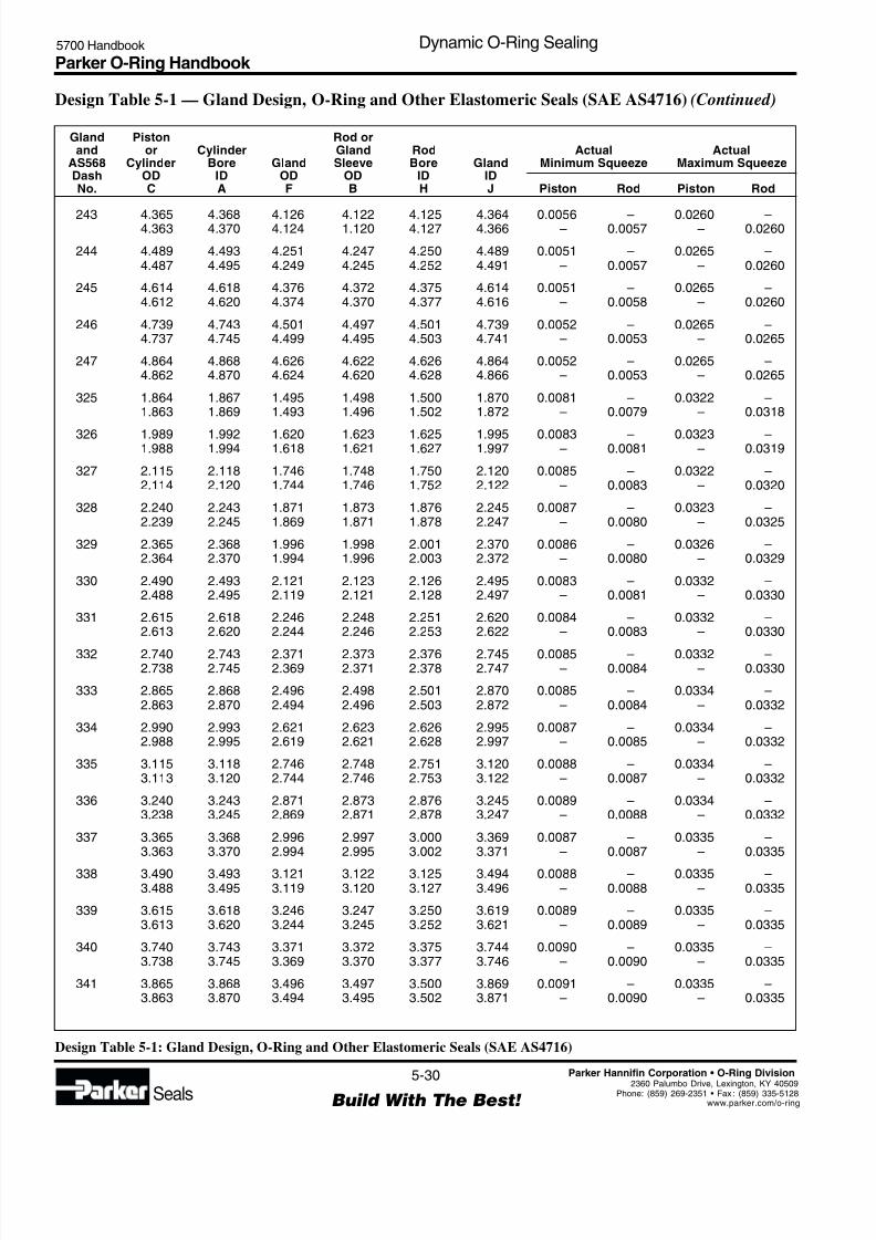
8/6/2019 Dynamic Oring Sealing
http://slidepdf.com/reader/full/dynamic-oring-sealing 30/49
Parker O-Ring Handbook 5700 Handbook Dynamic O-Ring Sealing
5-30
Build With The Best! Seals
Parker Hannifin Corporation • O-Ring Division
2360 Palumbo Drive, Lexington, KY 40509Phone: (859) 269-2351 • Fax : (859) 335-5128www.parker.com/o-ring
Gland Piston Rod orand or Cylinder Gland Rod Actual Actual
AS568 Cylinder Bore Gland Sleeve Bore Gland Minimum Squeeze Maximum SqueezeDash OD ID OD OD ID IDNo. C A F B H J Piston Rod Piston Rod
Design Table 5-1: Gland Design, O-Ring and Other Elastomeric Seals (SAE AS4716)
243 4.365 4.368 4.126 4.122 4.125 4.364 0.0056 – 0.0260 –4.363 4.370 4.124 1.120 4.127 4.366 – 0.0057 – 0.0260
244 4.489 4.493 4.251 4.247 4.250 4.489 0.0051 – 0.0265 –4.487 4.495 4.249 4.245 4.252 4.491 – 0.0057 – 0.0260
245 4.614 4.618 4.376 4.372 4.375 4.614 0.0051 – 0.0265 –4.612 4.620 4.374 4.370 4.377 4.616 – 0.0058 – 0.0260
246 4.739 4.743 4.501 4.497 4.501 4.739 0.0052 – 0.0265 –4.737 4.745 4.499 4.495 4.503 4.741 – 0.0053 – 0.0265
247 4.864 4.868 4.626 4.622 4.626 4.864 0.0052 – 0.0265 –4.862 4.870 4.624 4.620 4.628 4.866 – 0.0053 – 0.0265
325 1.864 1.867 1.495 1.498 1.500 1.870 0.0081 – 0.0322 –1.863 1.869 1.493 1.496 1.502 1.872 – 0.0079 – 0.0318
326 1.989 1.992 1.620 1.623 1.625 1.995 0.0083 – 0.0323 –1.988 1.994 1.618 1.621 1.627 1.997 – 0.0081 – 0.0319
327 2.115 2.118 1.746 1.748 1.750 2.120 0.0085 – 0.0322 –2.114 2.120 1.744 1.746 1.752 2.122 – 0.0083 – 0.0320
328 2.240 2.243 1.871 1.873 1.876 2.245 0.0087 – 0.0323 –2.239 2.245 1.869 1.871 1.878 2.247 – 0.0080 – 0.0325
329 2.365 2.368 1.996 1.998 2.001 2.370 0.0086 – 0.0326 –2.364 2.370 1.994 1.996 2.003 2.372 – 0.0080 – 0.0329
330 2.490 2.493 2.121 2.123 2.126 2.495 0.0083 – 0.0332 –2.488 2.495 2.119 2.121 2.128 2.497 – 0.0081 – 0.0330
331 2.615 2.618 2.246 2.248 2.251 2.620 0.0084 – 0.0332 –2.613 2.620 2.244 2.246 2.253 2.622 – 0.0083 – 0.0330
332 2.740 2.743 2.371 2.373 2.376 2.745 0.0085 – 0.0332 –2.738 2.745 2.369 2.371 2.378 2.747 – 0.0084 – 0.0330
333 2.865 2.868 2.496 2.498 2.501 2.870 0.0085 – 0.0334 –2.863 2.870 2.494 2.496 2.503 2.872 – 0.0084 – 0.0332
334 2.990 2.993 2.621 2.623 2.626 2.995 0.0087 – 0.0334 –2.988 2.995 2.619 2.621 2.628 2.997 – 0.0085 – 0.0332
335 3.115 3.118 2.746 2.748 2.751 3.120 0.0088 – 0.0334 –3.113 3.120 2.744 2.746 2.753 3.122 – 0.0087 – 0.0332
336 3.240 3.243 2.871 2.873 2.876 3.245 0.0089 – 0.0334 –3.238 3.245 2.869 2.871 2.878 3.247 – 0.0088 – 0.0332
337 3.365 3.368 2.996 2.997 3.000 3.369 0.0087 – 0.0335 –3.363 3.370 2.994 2.995 3.002 3.371 – 0.0087 – 0.0335
338 3.490 3.493 3.121 3.122 3.125 3.494 0.0088 – 0.0335 –3.488 3.495 3.119 3.120 3.127 3.496 – 0.0088 – 0.0335
339 3.615 3.618 3.246 3.247 3.250 3.619 0.0089 – 0.0335 –3.613 3.620 3.244 3.245 3.252 3.621 – 0.0089 – 0.0335
340 3.740 3.743 3.371 3.372 3.375 3.744 0.0090 – 0.0335 –3.738 3.745 3.369 3.370 3.377 3.746 – 0.0090 – 0.0335
341 3.865 3.868 3.496 3.497 3.500 3.869 0.0091 – 0.0335 –3.863 3.870 3.494 3.495 3.502 3.871 – 0.0090 – 0.0335
Design Table 5-1 — Gland Design, O-Ring and Other Elastomeric Seals (SAE AS4716) (Continued)
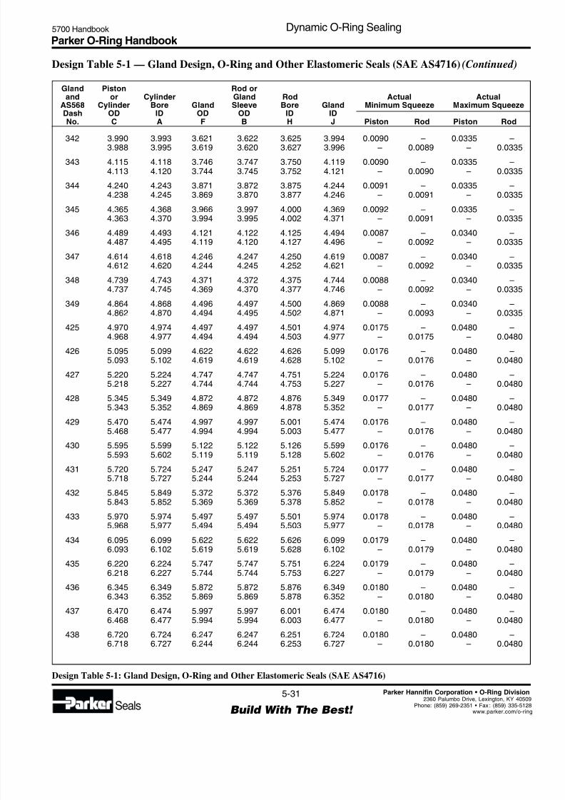
8/6/2019 Dynamic Oring Sealing
http://slidepdf.com/reader/full/dynamic-oring-sealing 31/49
Parker O-Ring Handbook 5700 Handbook Dynamic O-Ring Sealing
5-31
Build With The Best! Seals
Parker Hannifin Corporation • O-Ring Division
2360 Palumbo Drive, Lexington, KY 4050Phone: (859) 269-2351 • Fax : (859) 335-512www.parker.com/o-rin
Gland Piston Rod orand or Cylinder Gland Rod Actual Actual
AS568 Cylinder Bore Gland Sleeve Bore Gland Minimum Squeeze Maximum SqueezeDash OD ID OD OD ID IDNo. C A F B H J Piston Rod Piston Rod
Design Table 5-1: Gland Design, O-Ring and Other Elastomeric Seals (SAE AS4716)
Design Table 5-1 — Gland Design, O-Ring and Other Elastomeric Seals (SAE AS4716) (Continued)
342 3.990 3.993 3.621 3.622 3.625 3.994 0.0090 – 0.0335 –3.988 3.995 3.619 3.620 3.627 3.996 – 0.0089 – 0.0335
343 4.115 4.118 3.746 3.747 3.750 4.119 0.0090 – 0.0335 –4.113 4.120 3.744 3.745 3.752 4.121 – 0.0090 – 0.0335
344 4.240 4.243 3.871 3.872 3.875 4.244 0.0091 – 0.0335 –4.238 4.245 3.869 3.870 3.877 4.246 – 0.0091 – 0.0335
345 4.365 4.368 3.966 3.997 4.000 4.369 0.0092 – 0.0335 –4.363 4.370 3.994 3.995 4.002 4.371 – 0.0091 – 0.0335
346 4.489 4.493 4.121 4.122 4.125 4.494 0.0087 – 0.0340 –4.487 4.495 4.119 4.120 4.127 4.496 – 0.0092 – 0.0335
347 4.614 4.618 4.246 4.247 4.250 4.619 0.0087 – 0.0340 –4.612 4.620 4.244 4.245 4.252 4.621 – 0.0092 – 0.0335
348 4.739 4.743 4.371 4.372 4.375 4.744 0.0088 – 0.0340 –4.737 4.745 4.369 4.370 4.377 4.746 – 0.0092 – 0.0335
349 4.864 4.868 4.496 4.497 4.500 4.869 0.0088 – 0.0340 –4.862 4.870 4.494 4.495 4.502 4.871 – 0.0093 – 0.0335
425 4.970 4.974 4.497 4.497 4.501 4.974 0.0175 – 0.0480 –4.968 4.977 4.494 4.494 4.503 4.977 – 0.0175 – 0.0480
426 5.095 5.099 4.622 4.622 4.626 5.099 0.0176 – 0.0480 –5.093 5.102 4.619 4.619 4.628 5.102 – 0.0176 – 0.0480
427 5.220 5.224 4.747 4.747 4.751 5.224 0.0176 – 0.0480 –5.218 5.227 4.744 4.744 4.753 5.227 – 0.0176 – 0.0480
428 5.345 5.349 4.872 4.872 4.876 5.349 0.0177 – 0.0480 –5.343 5.352 4.869 4.869 4.878 5.352 – 0.0177 – 0.0480
429 5.470 5.474 4.997 4.997 5.001 5.474 0.0176 – 0.0480 –5.468 5.477 4.994 4.994 5.003 5.477 – 0.0176 – 0.0480
430 5.595 5.599 5.122 5.122 5.126 5.599 0.0176 – 0.0480 –5.593 5.602 5.119 5.119 5.128 5.602 – 0.0176 – 0.0480
431 5.720 5.724 5.247 5.247 5.251 5.724 0.0177 – 0.0480 –5.718 5.727 5.244 5.244 5.253 5.727 – 0.0177 – 0.0480
432 5.845 5.849 5.372 5.372 5.376 5.849 0.0178 – 0.0480 –5.843 5.852 5.369 5.369 5.378 5.852 – 0.0178 – 0.0480
433 5.970 5.974 5.497 5.497 5.501 5.974 0.0178 – 0.0480 –5.968 5.977 5.494 5.494 5.503 5.977 – 0.0178 – 0.0480
434 6.095 6.099 5.622 5.622 5.626 6.099 0.0179 – 0.0480 –6.093 6.102 5.619 5.619 5.628 6.102 – 0.0179 – 0.0480
435 6.220 6.224 5.747 5.747 5.751 6.224 0.0179 – 0.0480 –6.218 6.227 5.744 5.744 5.753 6.227 – 0.0179 – 0.0480
436 6.345 6.349 5.872 5.872 5.876 6.349 0.0180 – 0.0480 –6.343 6.352 5.869 5.869 5.878 6.352 – 0.0180 – 0.0480
437 6.470 6.474 5.997 5.997 6.001 6.474 0.0180 – 0.0480 –6.468 6.477 5.994 5.994 6.003 6.477 – 0.0180 – 0.0480
438 6.720 6.724 6.247 6.247 6.251 6.724 0.0180 – 0.0480 –6.718 6.727 6.244 6.244 6.253 6.727 – 0.0180 – 0.0480

8/6/2019 Dynamic Oring Sealing
http://slidepdf.com/reader/full/dynamic-oring-sealing 32/49
Parker O-Ring Handbook 5700 Handbook Dynamic O-Ring Sealing
5-32
Build With The Best! Seals
Parker Hannifin Corporation • O-Ring Division
2360 Palumbo Drive, Lexington, KY 40509Phone: (859) 269-2351 • Fax : (859) 335-5128www.parker.com/o-ring
Gland Piston Rod orand or Cylinder Gland Rod Actual Actual
AS568 Cylinder Bore Gland Sleeve Bore Gland Minimum Squeeze Maximum SqueezeDash OD ID OD OD ID IDNo. C A F B H J Piston Rod Piston Rod
Design Table 5-1: Gland Design, O-Ring and Other Elastomeric Seals (SAE AS4716)
439 6.970 6.974 6.497 6.497 6.501 6.974 0.0181 – 0.0480 –6.968 6.977 6.494 6.494 6.504 6.977 – 0.0176 – 0.0485
440 7.220 7.224 6.747 6.747 6.751 7.224 0.0182 – 0.0480 –7.218 7.227 6.744 6.744 6.754 7.227 – 0.0177 – 0.0485
441 7.470 7.474 6.997 6.997 7.001 7.474 0.0182 – 0.0480 –7.468 7.477 6.994 6.994 7.004 7.477 – 0.0177 – 0.0485
442 7.720 7.724 7.247 7.247 7.251 7.724 0.0181 – 0.0480 –7.718 7.727 7.244 7.244 7.254 7.727 – 0.0176 – 0.0485
443 7.970 7.974 7.497 7.497 7.501 7.974 0.0182 – 0.0480 –7.968 7.977 7.494 7.494 7.504 7.977 – 0.0177 – 0.0485
444 8.220 8.224 7.747 7.747 7.751 8.224 0.0183 – 0.0480 –8.218 8.227 7.744 7.744 7.754 8.227 – 0.0178 – 0.0485
445 8.470 8.474 7.997 7.997 8.001 8.474 0.0183 – 0.0480 –8.468 8.477 7.994 7.994 8.004 8.477 – 0.0178 – 0.0485
446 8.970 8.974 8.497 8.497 8.501 8.974 0.0177 – 0.0485 –8.967 8.977 8.494 8.494 8.504 8.977 – 0.0177 – 0.0485
447 9.470 9.474 8.997 8.997 9.001 9.474 0.0168 – 0.0485 –9.467 9.478 8.994 8.994 9.004 9.478 – 0.0173 – 0.0485
448 9.970 9.974 9.497 9.497 9.501 9.974 0.0169 – 0.0485 –9.967 9.978 9.494 9.494 9.504 9.978 – 0.0174 – 0.0485
449 10.470 10.474 9.997 9.997 10.001 10.474 0.0170 – 0.0485 –10.467 10.478 9.994 9.994 10.004 10.478 – 0.0175 – 0.0485
450 10.970 10.974 10.497 10.497 10.501 10.974 0.0170 – 0.0485 –10.967 10.978 10.494 10.494 10.504 10.978 – 0.0175 – 0.0485
451 11.470 11.474 10.997 10.997 11.001 11.474 0.0170 – 0.0485 –11.467 11.478 10.994 10.994 11.004 11.478 – 0.0176 – 0.0485
452 11.970 11.974 11.497 11.497 11.501 11.974 0.0171 – 0.0485 –11.967 11.978 11.494 11.494 11.504 11.978 – 0.0176 – 0.0485
453 12.470 12.474 11.997 11.997 12.001 12.474 0.0172 – 0.0485 –12.467 12.478 11.994 11.994 12.004 12.478 – 0.0177 – 0.0485
454 12.970 12.974 12.497 12.497 12.501 12.974 0.0173 – 0.0485 –12.967 12.978 12.494 12.494 12.504 12.978 – 0.0178 – 0.0485
455 13.470 13.474 12.997 12.997 13.001 13.474 0.0173 – 0.0485 –13.467 13.478 12.994 12.994 13.004 13.478 – 0.0178 – 0.0485
456 13.970 13.974 13.497 13.497 13.501 13.974 0.0172 – 0.0485 –13.967 13.978 13.494 13.494 13.504 13.978 – 0.0177 – 0.0485
457 14.470 14.474 13.997 13.997 14.001 14.474 0.0173 – 0.0485 –14.467 14.478 13.994 13.994 14.004 14.478 – 0.0178 – 0.0485
458 14.970 14.974 14.497 14.497 14.501 14.974 0.0173 – 0.0485 –14.967 14.978 14.494 14.494 14.504 14.978 – 0.0178 – 0.0485
459 15.470 15.474 14.997 14.997 15.001 15.474 0.0174 – 0.0485 –15.467 15.478 14.994 14.994 15.004 15.478 – 0.0179 – 0.0485
460 15.970 15.974 15.497 15.497 15.501 15.974 0.0174 – 0.0485 –15.967 15.978 15.494 15.494 15.504 15.978 – 0.0179 – 0.0485
Design Table 5-1 — Gland Design, O-Ring and Other Elastomeric Seals (SAE AS4716) (Continued)
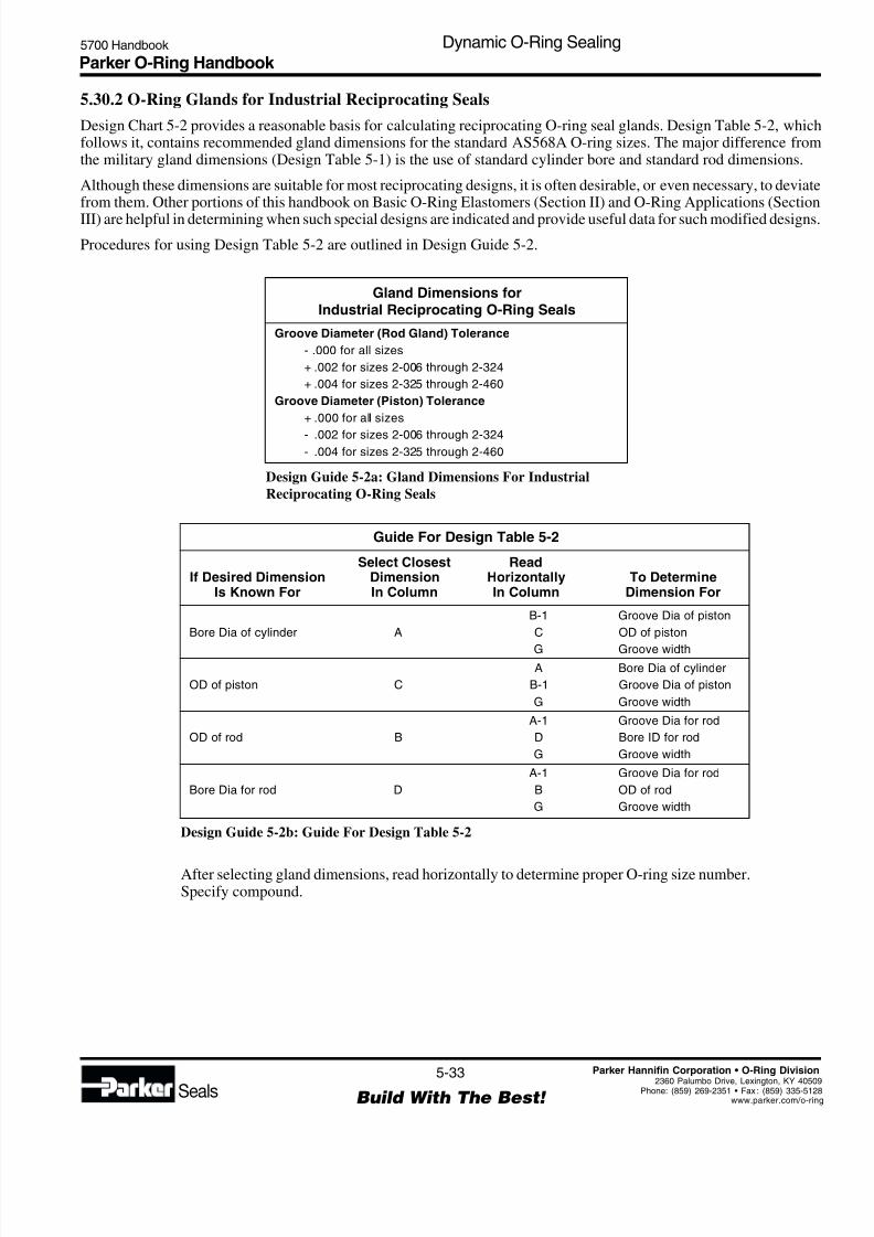
8/6/2019 Dynamic Oring Sealing
http://slidepdf.com/reader/full/dynamic-oring-sealing 33/49
Parker O-Ring Handbook 5700 Handbook Dynamic O-Ring Sealing
5-33
Build With The Best! Seals
Parker Hannifin Corporation • O-Ring Division
2360 Palumbo Drive, Lexington, KY 4050Phone: (859) 269-2351 • Fax : (859) 335-512www.parker.com/o-rin
Gland Dimensions forIndustrial Reciprocating O-Ring Seals
Groove Diameter (Rod Gland) Tolerance
- .000 for all sizes
+ .002 for sizes 2-006 through 2-324
+ .004 for sizes 2-325 through 2-460
Groove Diameter (Piston) Tolerance
+ .000 for all sizes
- .002 for sizes 2-006 through 2-324- .004 for sizes 2-325 through 2-460
Design Guide 5-2a: Gland Dimensions For Industrial
Reciprocating O-Ring Seals
5.30.2 O-Ring Glands for Industrial Reciprocating Seals
Design Chart 5-2 provides a reasonable basis for calculating reciprocating O-ring seal glands. Design Table 5-2, whichfollows it, contains recommended gland dimensions for the standard AS568A O-ring sizes. The major difference fromthe military gland dimensions (Design Table 5-1) is the use of standard cylinder bore and standard rod dimensions.
Although these dimensions are suitable for most reciprocating designs, it is often desirable, or even necessary, to deviatefrom them. Other portions of this handbook on Basic O-Ring Elastomers (Section II) and O-Ring Applications (Section
III) are helpful in determining when such special designs are indicated and provide useful data for such modified designs
Procedures for using Design Table 5-2 are outlined in Design Guide 5-2.
Guide For Design Table 5-2
Select Closest ReadIf Desired Dimension Dimension Horizontally To Determine
Is Known For In Column In Column Dimension For
B-1 Groove Dia of piston
Bore Dia of cylinder A C OD of piston
G Groove widthA Bore Dia of cylinder
OD of piston C B-1 Groove Dia of piston
G Groove width
A-1 Groove Dia for rod
OD of rod B D Bore ID for rod
G Groove width
A-1 Groove Dia for rod
Bore Dia for rod D B OD of rod
G Groove width
Design Guide 5-2b: Guide For Design Table 5-2
After selecting gland dimensions, read horizontally to determine proper O-ring size number.Specify compound.
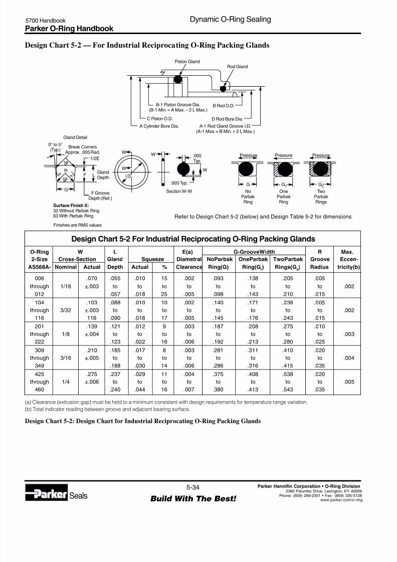
8/6/2019 Dynamic Oring Sealing
http://slidepdf.com/reader/full/dynamic-oring-sealing 34/49
Parker O-Ring Handbook 5700 Handbook Dynamic O-Ring Sealing
5-34
Build With The Best! Seals
Parker Hannifin Corporation • O-Ring Division
2360 Palumbo Drive, Lexington, KY 40509Phone: (859) 269-2351 • Fax : (859) 335-5128www.parker.com/o-ring
Design Chart 5-2 — For Industrial Reciprocating O-Ring Packing Glands
Piston GlandRod Gland
B Rod O.D.B-1 Piston Groove Dia.(B-1 Min. = A Max.– 2 L Max.)
D Rod Bore Dia.C Piston O.D.
A-1 Rod Gland Groove I.D.(A-1 Max. = B Min.+ 2 L Max.)
A Cylinder Bore Dia.
Gland Detail
1/2E
F L
G
R
16
X
32 X
0° to 5°(Typ.)
Break CornersApprox. .005 Rad.
GlandDepth
F Groove
Depth (Ref.)
Surface Finish X:32 Without Parbak Ring63 With Parbak Ring
No
ParbakRing
One
ParbakRing
Pressure.005Typ.
W
WW
W
I.D.
.003 Typ.
Section W-W
Pressure Pressure
Two
ParbakRings
G2G G1
Finishes are RMS values
Refer to Design Chart 5-2 (below) and Design Table 5-2 for dimensions.
O-Ring W L E(a) G-GrooveWidth R Max.
2-Size Cross-Section Gland Squeeze Diametral NoParbak OneParbak TwoParbak Groove Eccen-
AS568A- Nominal Actual Depth Actual % Clearance Ring(G) Ring(G1) Rings(G
2) Radius tricity(b)
006 .070 .055 .010 15 .002 .093 .138 .205 .005
through 1/16 ±.003 to to to to to to to to .002
012 .057 .018 25 .005 .098 .143 .210 .015104 .103 .088 .010 10 .002 .140 .171 .238 .005
through 3/32 ±.003 to to to to to to to to .002
116 116 .090 .018 17 .005 .145 .176 .243 .015
201 .139 .121 .012 9 .003 .187 .208 .275 .010
through 1/8 ±.004 to to to to to to to to .003
222 .123 .022 16 .006 .192 .213 .280 .025
309 .210 .185 .017 8 .003 .281 .311 .410 .020
through 3/16 ±.005 to to to to to to to to .004
349 .188 .030 14 .006 .286 .316 .415 .035
425 .275 .237 .029 11 .004 .375 .408 .538 .020
through 1/4 ±.006 to to to to to to to to .005
460 .240 .044 16 .007 .380 .413 .543 .035
Design Chart 5-2 For Industrial Reciprocating O-Ring Packing Glands
(a) Clearance (extrusion gap) must be held to a minimum consistent with design requirements for temperature range variation.
(b) Total indicator reading between groove and adjacent bearing surface.
Design Chart 5-2: Design Chart for Industrial Reciprocating O-Ring Packing Glands

8/6/2019 Dynamic Oring Sealing
http://slidepdf.com/reader/full/dynamic-oring-sealing 35/49
Parker O-Ring Handbook 5700 Handbook Dynamic O-Ring Sealing
5-35
Build With The Best! Seals
Parker Hannifin Corporation • O-Ring Division
2360 Palumbo Drive, Lexington, KY 4050Phone: (859) 269-2351 • Fax : (859) 335-512www.parker.com/o-rin
Design Table 5-2 — Gland Dimensions for Industrial Reciprocating O-Ring Seals,103.5 Bar (1500 PSI) Max.†
006 .114 .005 .254 .249 .234 .124 .139 *.247 .126
007 .145 .005 .285 .280 .265 .155 .170 *.278 .157
008 .176 .005 .316 .311 .296 .186 .201 *.309 .188
009 .208 .005 .070 .348 .343 .328 .218 .233 *.341 .220 .093
010 .239 .005 ±.003 .379 .374 .359 .249 .264 *.372 .251
011 .301 .005 .441 .436 .421 .311 .326 *.434 .313
012 .364 .005 .504 .499 .484 .374 .389 *.497 .376
104 .112 .005 .318 .312 .300 .124 .136 *.310 .126
105 .143 .005 .349 .343 .331 .155 .167 *.341 .157
106 .174 .005 .380 .374 .362 .186 .198 *.372 .188
107 .206 .005 .412 .406 .394 .218 .230 *.404 .220
108 .237 .005 .443 .437 .425 .249 .261 *.435 .251
109 .299 .005 .505 .499 .487 .311 .323 *.497 .313
110 .362 .005 .103 .568 .562 .550 .374 .386 *.560 .376 .140
111 .424 .005 ±.003 .630 .624 .612 .436 .488 *.622 .438
112 .487 .005 .693 .687 .675 .499 .511 *.685 .501
113 .549 .007 .755 .749 .737 .561 .573 *.747 .563
114 .612 .009 .818 .812 .800 .624 .636 .810 .626
115 .674 .009 .880 .874 .862 .686 .698 .872 .688
116 .737 .009 .943 .937 .925 .749 .761 .935 .751
201 .171 .005 .449 .437 .427 .185 .195 *.434 .188
202 .234 .005 .512 .500 .490 .248 .258 *.497 .251
203 .296 .005 .574 .562 .552 .310 .320 *.559 .313
204 .359 .005 .637 .625 .615 .373 .383 .662 .376
205 .421 .005 .699 .687 .677 .435 .445 .684 .438206 .484 .005 .762 .750 .740 .498 .508 .747 .501
207 .546 .007 .824 .812 .802 .560 .570 .809 .563
208 .609 .009 .887 .875 .865 .623 .633 .872 .626
209 .671 .009 .949 .937 .927 .685 .695 .934 .688
210 .734 .010 1.012 1.000 .990 .748 .758 .997 .751
211 .796 .010 .139 1.074 1.062 1.052 .810 .820 1.059 .813 .187
212 .859 .010 ±.004 1.137 1.125 1.115 .873 .883 1.122 .876
213 .921 .010 1.199 1.187 1.177 .935 .945 1.184 .938
214 .984 .010 1.262 1.250 1.240 .998 1.008 1.247 1.001
215 1.046 .010 1.324 1.312 1.302 1.060 1.070 1.309 1.063
216 1.109 .012 1.387 1.375 1.365 1.123 1.133 1.372 1.126
217 1.171 .012 1.449 1.437 1.427 1.185 1.195 1.434 1.188
218 1.234 .012 1.512 1.500 1.490 1.248 1.258 1.497 1.251
219 1.296 .012 1.574 1.562 1.552 1.310 1.320 1.559 1.313
220 1.359 .012 1.637 1.625 1.615 1.373 1.383 1.622 1.376
221 1.421 .012 1.699 1.687 1.677 1.435 1.445 1.684 1.438
222 1.484 .015 1.762 1.750 1.740 1.498 1.508 1.747 1.501
* These designs require considerable installation stretch. If assembly breakage is incurred use a compound having higher elongationor use a two-piece piston.
† This groove width does not permit the use of Parbak rings. For pressures above 103.5 Bar (1500 PSI), consult Design Chart 5-2 forgroove widths where Parbak rings must be used.
O-Ring
Size
Parker No.
2-
Dimensions
Mean
I.D. ± W O.D. (Ref)
A
Bore Dia.(Cylinder)
+.002-.000
A-1
Groove Dia.(Rod Gland)
+.002-.000
B
OD(Rod)
+.000-.002
B-1
Groove Dia.*(Piston)
+.000-.002
C
OD(Piston)
+.000-.001
D
Bore Dia.(Rod)
+.001-.000
G†
WidthGroove
+.005-.000
Design Table 5-2: Gland Dimensions for Industrial Reciprocating O-Ring Seals, 103.5 Bar (1500 PSI) Max. †
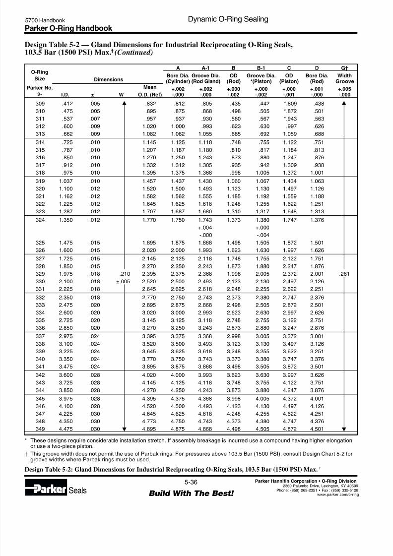
8/6/2019 Dynamic Oring Sealing
http://slidepdf.com/reader/full/dynamic-oring-sealing 36/49
Parker O-Ring Handbook 5700 Handbook Dynamic O-Ring Sealing
5-36
Build With The Best! Seals
Parker Hannifin Corporation • O-Ring Division
2360 Palumbo Drive, Lexington, KY 40509Phone: (859) 269-2351 • Fax : (859) 335-5128www.parker.com/o-ring
309 .412 .005 .832 .812 .805 .435 .442 *.809 .438
310 .475 .005 .895 .875 .868 .498 .505 *.872 .501
311 .537 .007 .957 .937 .930 .560 .567 *.943 .563
312 .600 .009 1.020 1.000 .993 .623 .630 .997 .626
313 .662 .009 1.082 1.062 1.055 .685 .692 1.059 .688
314 .725 .010 1.145 1.125 1.118 .748 .755 1.122 .751
315 .787 .010 1.207 1.187 1.180 .810 .817 1.184 .813
316 .850 .010 1.270 1.250 1.243 .873 .880 1.247 .876
317 .912 .010 1.332 1.312 1.305 .935 .942 1.309 .938
318 .975 .010 1.395 1.375 1.368 .998 1.005 1.372 1.001
319 1.037 .010 1.457 1.437 1.430 1.060 1.067 1.434 1.063
320 1.100 .012 1.520 1.500 1.493 1.123 1.130 1.497 1.126
321 1.162 .012 1.582 1.562 1.555 1.185 1.192 1.559 1.188
322 1.225 .012 1.645 1.625 1.618 1.248 1.255 1.622 1.251
323 1.287 .012 1.707 1.687 1.680 1.310 1.317 1.648 1.313
324 1.350 .012 1.770 1.750 1.743 1.373 1.380 1.747 1.376
+.004 +.000
-.000 -.004
325 1.475 .015 1.895 1.875 1.868 1.498 1.505 1.872 1.501
326 1.600 .015 2.020 2.000 1.993 1.623 1.630 1.997 1.626
327 1.725 .015 2.145 2.125 2.118 1.748 1.755 2.122 1.751
328 1.850 .015 2.270 2.250 2.243 1.873 1.880 2.247 1.876
329 1.975 .018 .210 2.395 2.375 2.368 1.998 2.005 2.372 2.001 .281
330 2.100 .018 ±.005 2.520 2.500 2.493 2.123 2.130 2.497 2.126
331 2.225 .018 2.645 2.625 2.618 2.248 2.255 2.622 2.251
332 2.350 .018 2.770 2.750 2.743 2.373 2.380 2.747 2.376
333 2.475 .020 2.895 2.875 2.868 2.498 2.505 2.872 2.501
334 2.600 .020 3.020 3.000 2.993 2.623 2.630 2.997 2.626
335 2.725 .020 3.145 3.125 3.118 2.748 2.755 3.122 2.751
336 2.850 .020 3.270 3.250 3.243 2.873 2.880 3.247 2.876
337 2.975 .024 3.395 3.375 3.368 2.998 3.005 3.372 3.001
338 3.100 .024 3.520 3.500 3.493 3.123 3.130 3.497 3.126
339 3.225 .024 3.645 3.625 3.618 3.248 3.255 3.622 3.251
340 3.350 .024 3.770 3.750 3.743 3.373 3.380 3.747 3.376
341 3.475 .024 3.895 3.875 3.868 3.498 3.505 3.872 3.501
342 3.600 .028 4.020 4.000 3.993 3.623 3.630 3.997 3.626
343 3.725 .028 4.145 4.125 4.118 3.748 3.755 4.122 3.751
344 3.850 .028 4.270 4.250 4.243 3.873 3.880 4.247 3.876
345 3.975 .028 4.395 4.375 4.368 3.998 4.005 4.372 4.001
346 4.100 .028 4.520 4.500 4.493 4.123 4.130 4.497 4.126
347 4.225 .030 4.645 4.625 4.618 4.248 4.255 4.622 4.251
348 4.350 .030 4.773 4.750 4.743 4.373 4.380 4.747 4.376
349 4.475 .030 4.895 4.875 4.868 4.498 4.505 4.872 4.501
O-Ring
Size
Parker No.
2-
Dimensions
Mean
I.D. ± W O.D. (Ref)
A
Bore Dia.(Cylinder)
+.002
-.000
A-1
Groove Dia.(Rod Gland)
+.002
-.000
B
OD(Rod)
+.000
-.002
B-1
Groove Dia.*(Piston)
+.000
-.002
C
OD(Piston)
+.000
-.001
D
Bore Dia.(Rod)
+.001
-.000
G†
WidthGroove
+.005
-.000
* These designs require considerable installation stretch. If assembly breakage is incurred use a compound having higher elongationor use a two-piece piston.
† This groove width does not permit the use of Parbak rings. For pressures above 103.5 Bar (1500 PSI), consult Design Chart 5-2 forgroove widths where Parbak rings must be used.
Design Table 5-2 — Gland Dimensions for Industrial Reciprocating O-Ring Seals,103.5 Bar (1500 PSI) Max.† (Continued)
Design Table 5-2: Gland Dimensions for Industrial Reciprocating O-Ring Seals, 103.5 Bar (1500 PSI) Max.†

8/6/2019 Dynamic Oring Sealing
http://slidepdf.com/reader/full/dynamic-oring-sealing 37/49
Parker O-Ring Handbook 5700 Handbook Dynamic O-Ring Sealing
5-37
Build With The Best! Seals
Parker Hannifin Corporation • O-Ring Division
2360 Palumbo Drive, Lexington, KY 4050Phone: (859) 269-2351 • Fax : (859) 335-512www.parker.com/o-rin
425 4.475 .033 5.025 5.002 4.971 4.497 4.528 4.998 4.501
426 4.600 .033 5.150 5.127 5.096 4.622 4.653 5.123 4.626
427 4.725 .033 5.275 5.252 5.221 4.747 4.778 5.248 4.751
428 4.850 .033 5.400 5.377 5.346 4.872 4.903 5.373 4.876
429 4.975 .037 5.525 5.502 5.471 4.997 5.028 5.498 5.001
430 5.100 .037 5.650 5.627 5.596 5.122 5.153 5.623 5.126
431 5.225 .037 5.775 5.752 5.721 5.247 5.278 5.748 5.251
432 5.350 .037 5.900 5.877 5.846 5.372 5.403 5.873 5.376
433 5.475 .037 6.025 6.002 5.971 5.497 5.528 5.998 5.501
434 5.600 .037 6.150 6.127 6.096 5.622 5.653 6.123 5.626
435 5.725 .037 6.275 6.252 6.221 5.747 5.778 6.248 5.751
436 5.850 .037 6.400 6.377 6.346 5.872 5.903 6.373 5.876
437 5.975 .037 6.525 6.502 6.471 5.997 6.028 6.498 6.001438 6.225 .040 6.775 6.752 6.721 6.247 6.278 6.748 6.251
439 6.475 .040 7.025 7.002 6.971 6.497 6.528 6.998 6.501
440 6.725 .040 7.275 7.252 7.221 6.747 6.778 7.248 6.751
441 6.975 .040 7.525 7.502 7.471 6.997 7.028 7.498 7.001
442 7.225 .045 .275 7.775 7.752 4.721 7.247 7.278 7.748 7.251 .375
443 7.475 .045 ±.006 8.025 8.002 7.971 7.497 7.528 7.998 7.501
444 7.725 .045 8.275 8.252 8.221 7.747 7.778 8.248 7.751
445 7.975 .045 8.525 8.502 8.471 7.997 8.028 8.498 8.001
446 8.475 .055 9.025 9.002 8.971 8.497 8.528 8.998 8.501
447 8.975 .055 9.525 9.502 9.471 8.997 9.028 9.498 9.001
448 9.475 .055 10.025 10.002 9.971 9.497 9.528 9.998 9.501
449 9.975 .055 10.525 10.502 10.471 9.997 10.028 10.498 10.001
450 10.475 .060 11.025 11.002 10.971 10.497 10.528 10.998 10.501
451 10.975 .060 11.525 11.502 11.471 10.997 11.028 11.498 11.001
452 11.475 .060 12.025 12.002 11.971 11.497 11.528 11.998 11.501
453 11.975 .060 12.525 12.502 12.471 11.997 12.028 12.498 12.001
454 12.475 .060 13.025 13.002 12.971 12.497 12.528 12.998 12.501
455 12.975 .060 13.525 13.502 13.471 12.997 13.028 13.498 13.001
456 13.475 .070 14.025 14.002 13.971 13.497 13.528 13.998 13.501
457 13.975 .070 14.525 14.502 14.471 13.997 14.028 14.498 14.001
458 14.475 .070 15.025 15.002 14.971 14.497 14.528 14.998 14.501
459 14.975 .070 15.525 15.502 15.471 14.997 15.028 15.498 15.001
460 15.475 .070 16.025 16.002 15.971 15.497 15.528 15.998 15.501
O-Ring
Size
Parker No.
2-
Dimensions
Mean
I.D. ± W O.D. (Ref)
A
Bore Dia.(Cylinder)
+.002-.000
A-1
Groove Dia.(Rod Gland)
+.004-.000
B
OD(Rod)
+.000-.002
B-1
Groove Dia.*(Piston)
+.000-.004
C
OD(Piston)
+.000-.001
D
Bore Dia.(Rod)
+.001-.000
G†
WidthGroove
+.005-.000
* These designs require considerable installation stretch. If assembly breakage is incurred use a compound having higher elongation
or use a two-piece piston.† This groove width does not permit the use of Parbak rings. For pressures above 103.5 Bar (1500 PSI), consult Design Chart 5-2 for
groove widths where Parbak rings must be used.
Design Table 5-2 — Gland Dimensions for Industrial Reciprocating O-Ring Seals,103.5 Bar (1500 PSI) Max.† (Continued)
Design Table 5-2: Gland Dimensions for Industrial Reciprocating O-Ring Seals, 103.5 Bar (1500 PSI) Max. †
8/6/2019 Dynamic Oring Sealing
http://slidepdf.com/reader/full/dynamic-oring-sealing 38/49
Parker O-Ring Handbook 5700 Handbook Dynamic O-Ring Sealing
5-38
Build With The Best! Seals
Parker Hannifin Corporation • O-Ring Division
2360 Palumbo Drive, Lexington, KY 40509Phone: (859) 269-2351 • Fax : (859) 335-5128www.parker.com/o-ring
5.30.3 O-Ring Glands for Pneumatic Floating Piston Ring Seals
Design Chart 5-3 provides the basis for calculating gland dimensions. For standard O-ring sizes, these dimensions havebeen calculated and are listed in Design Table 5-3. The procedures for the use of Design Table 5-3 are outlined in DesignGuide 5-3.
Guide For Design Table 5-3
Select Closest ReadIf Desired Dimension Dimension Horizontally To Determine
Is Known For In Column In Column Dimension For
Bore Dia of cylinder B-1 Groove Dia of piston
A C OD of piston
G Groove width
A Bore Dia of cylinder
OD of piston C B-1 Groove Dia of piston
G Groove width
Design Guide 5-3: Guide For Design Table 5-3
After selecting gland dimensions, read horizontally to determine proper O-ring size number.
Specify compound.
Refer to 8-2, Military Fluid Specification Description, Fluid Compatibility Tables, or Table3-1 to select the proper compound. The effective part number for an O-ring consists of botha size number and a compound number.

8/6/2019 Dynamic Oring Sealing
http://slidepdf.com/reader/full/dynamic-oring-sealing 39/49
Parker O-Ring Handbook 5700 Handbook Dynamic O-Ring Sealing
5-39
Build With The Best! Seals
Parker Hannifin Corporation • O-Ring Division
2360 Palumbo Drive, Lexington, KY 4050Phone: (859) 269-2351 • Fax : (859) 335-512www.parker.com/o-rin
Design Chart 5-3 — Floating Pneumatic Piston Ring Seal Glands 13.8 Bar (200 PSI) Max.
B-1 Piston Groove O.D.(B-1 Max. = A Min.– 2 L Min.)
A Cylinder Bore Dia.[A Min. = (O-Ring Mean O.D.) — P]
Gland Detail
1/2 E
F L
G
R
16
3 2
32 3 2
0° to 5° Typ.(0° Preferred)
Break EdgesApprox. .005 Rad.
GlandDepth
F GrooveDepth (Ref.)
Rod Seal GlandUse Data in Chart 5-2 andTable 5-2 for IndustrialReciprocating Seals.Floating O-ring DesignDoes Not Apply toRod Seals.
C Piston O.D.
1/2 E
.005Typ.
W
WW
W
I . D .
.003 Typ.
Section W-W
Finishes are RMS values
Design Chart 5-3 — Floating Pneumatic Piston Ring Seal GlandsO-Ring W P (c)Size (a) Cross Section Peripheral L G E RParker Squeeze Gland Groove Diametral Eccentricity GrooveNo. 2- Nominal Actual (Variable) Depth Width Clearance Max. (b) Radius
006 .035 .072 .075 .002 .005
through 1/16 .070 to to to to .002 to012 ±.003 .042 .076 .079 .010 .015104 .038 .105 .111 .002 .005
through 3/32 .103 to to to to .002 to116 ±.003 .062 .109 .115 .010 .015201 .061 .143 .151 .003 .010
through 1/8 .139 to to to to .003 to222 ±.004 .082 .147 .155 .011 .025309 .084 .214 .229 .003 .020
through 3/16 .210 to to to to .004 to349 ±.005 .124 .218 .233 .011 .035425 .140 .282 .301 .004 .020
through 1/4 .275 to to to to .005 to460 ±.006 .175 .286 .305 .012 .035
(a) Only sizes listed are recommended for this design.(b) Total indicator reading between groove and adjacent bearing surface.
(c) Use to calculate Amin diameter.
Design Chart 5-3: Design Chart for Floating Pneumatic Piston Ring Seal Glands
Refer to Design Chart 5-3 (below) and Design Table 5-3 for dimensions.
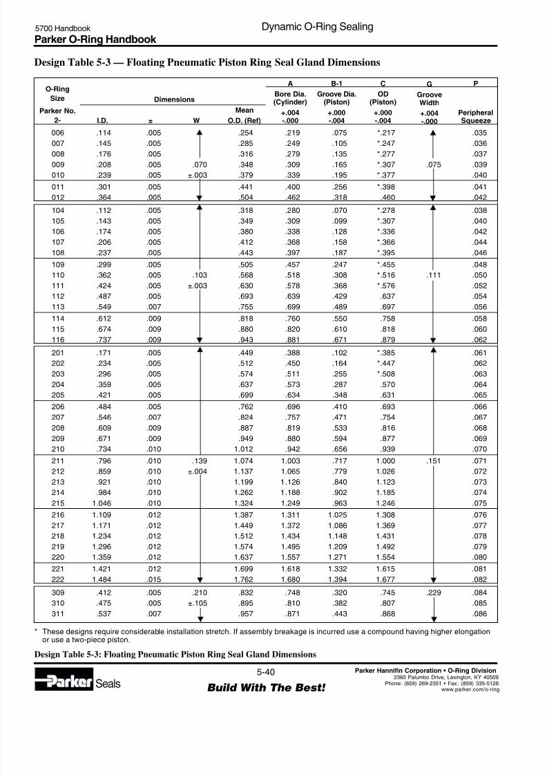
8/6/2019 Dynamic Oring Sealing
http://slidepdf.com/reader/full/dynamic-oring-sealing 40/49
Parker O-Ring Handbook 5700 Handbook Dynamic O-Ring Sealing
5-40
Build With The Best! Seals
Parker Hannifin Corporation • O-Ring Division
2360 Palumbo Drive, Lexington, KY 40509Phone: (859) 269-2351 • Fax : (859) 335-5128www.parker.com/o-ring
Design Table 5-3 — Floating Pneumatic Piston Ring Seal Gland Dimensions
O-Ring
Size
Parker No.
2-
Dimensions
Mean
I.D. ± W O.D. (Ref)
A
Bore Dia.(Cylinder)
+.004-.000
B-1
Groove Dia.(Piston)
+.000-.004
C
OD(Piston)
+.000-.004
G
GrooveWidth
+.004-.000
P
PeripheralSqueeze
006 .114 .005 .254 .219 .075 *.217 .035007 .145 .005 .285 .249 .105 *.247 .036
008 .176 .005 .316 .279 .135 *.277 .037
009 .208 .005 .070 .348 .309 .165 *.307 .075 .039
010 .239 .005 ±.003 .379 .339 .195 *.377 .040
011 .301 .005 .441 .400 .256 *.398 .041
012 .364 .005 .504 .462 .318 .460 .042
104 .112 .005 .318 .280 .070 *.278 .038
105 .143 .005 .349 .309 .099 *.307 .040
106 .174 .005 .380 .338 .128 *.336 .042
107 .206 .005 .412 .368 .158 *.366 .044
108 .237 .005 .443 .397 .187 *.395 .046
109 .299 .005 .505 .457 .247 *.455 .048
110 .362 .005 .103 .568 .518 .308 *.516 .111 .050
111 .424 .005 ±.003 .630 .578 .368 *.576 .052
112 .487 .005 .693 .639 .429 .637 .054
113 .549 .007 .755 .699 .489 .697 .056
114 .612 .009 .818 .760 .550 .758 .058
115 .674 .009 .880 .820 .610 .818 .060
116 .737 .009 .943 .881 .671 .879 .062
201 .171 .005 .449 .388 .102 *.385 .061
202 .234 .005 .512 .450 .164 *.447 .062
203 .296 .005 .574 .511 .255 *.508 .063
204 .359 .005 .637 .573 .287 .570 .064
205 .421 .005 .699 .634 .348 .631 .065
206 .484 .005 .762 .696 .410 .693 .066207 .546 .007 .824 .757 .471 .754 .067
208 .609 .009 .887 .819 .533 .816 .068
209 .671 .009 .949 .880 .594 .877 .069
210 .734 .010 1.012 .942 .656 .939 .070
211 .796 .010 .139 1.074 1.003 .717 1.000 .151 .071
212 .859 .010 ±.004 1.137 1.065 .779 1.026 .072
213 .921 .010 1.199 1.126 .840 1.123 .073
214 .984 .010 1.262 1.188 .902 1.185 .074
215 1.046 .010 1.324 1.249 .963 1.246 .075
216 1.109 .012 1.387 1.311 1.025 1.308 .076
217 1.171 .012 1.449 1.372 1.086 1.369 .077
218 1.234 .012 1.512 1.434 1.148 1.431 .078
219 1.296 .012 1.574 1.495 1.209 1.492 .079
220 1.359 .012 1.637 1.557 1.271 1.554 .080
221 1.421 .012 1.699 1.618 1.332 1.615 .081
222 1.484 .015 1.762 1.680 1.394 1.677 .082
309 .412 .005 .210 .832 .748 .320 .745 .229 .084
310 .475 .005 ±.105 .895 .810 .382 .807 .085
311 .537 .007 .957 .871 .443 .868 .086
* These designs require considerable installation stretch. If assembly breakage is incurred use a compound having higher elongationor use a two-piece piston.
Design Table 5-3: Floating Pneumatic Piston Ring Seal Gland Dimensions
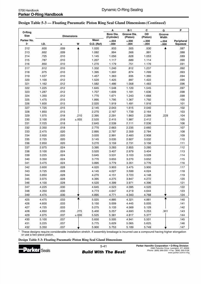
8/6/2019 Dynamic Oring Sealing
http://slidepdf.com/reader/full/dynamic-oring-sealing 41/49
Parker O-Ring Handbook 5700 Handbook Dynamic O-Ring Sealing
5-41
Build With The Best! Seals
Parker Hannifin Corporation • O-Ring Division
2360 Palumbo Drive, Lexington, KY 4050Phone: (859) 269-2351 • Fax : (859) 335-512www.parker.com/o-rin
O-Ring
Size
Parker No.
2-
Dimensions
Mean
I.D. ± W O.D. (Ref)
A
Bore Dia.(Cylinder)
+.004-.000
B-1
Groove Dia.(Piston)
+.000-.004
C
OD(Piston)
+.000-.004
G
GrooveWidth
+.004-.000
P
PeripheralSqueeze
312 .600 .009 1.020 .933 .505 .930 .087313 .662 .009 1.082 .994 .566 .991 .088
314 .725 .010 1.145 1.056 .628 1.053 .089
315 .787 .010 1.207 1.117 .689 1.114 .090
316 .850 .010 1.270 1.179 .751 1.176 .091
317 .912 .010 1.332 1.240 .812 1.237 .092
318 .975 .010 1.395 1.302 .874 1.299 .093
319 1.037 .010 1.457 1.363 .935 1.360 .094
320 1.100 .012 1.520 1.425 .997 1.422 .095
321 1.162 .012 1.582 1.486 1.058 1.483 .096
322 1.225 .012 1.645 1.548 1.120 1.545 .097
323 1.287 .012 1.707 1.609 1.181 1.636 .098
324 1.350 .012 1.770 1.671 1.243 1.668 .099
325 1.475 .015 1.895 1.795 1.367 1.792 .100326 1.600 .015 2.020 1.919 1.491 1.916 .101
327 1.725 .015 2.145 2.043 1.615 2.040 .102
328 1.850 .015 2.270 2.167 1.739 2.164 .103
329 1.975 .018 .210 2.395 2.291 1.863 2.288 .229 .104
330 2.100 .018 ±.005 2.520 2.415 1.987 2.412 .105
331 2.225 .018 2.645 2.539 2.111 2.536 .106
332 2.350 .018 2.770 2.663 2.235 2.660 .107
333 2.475 .020 2.895 2.787 2.359 2.784 .108
334 2.600 .020 3.020 2.991 2.483 2.908 .109
335 2.725 .020 3.145 3.035 2.607 3.032 .110
336 2.850 .020 3.270 3.159 2.731 3.156 .111
337 2.975 .024 3.395 3.283 2.855 3.280 .112
338 3.100 .024 3.520 3.407 2.979 3.404 .113
339 3.225 .024 3.645 3.531 3.103 3.528 .114
340 3.350 .024 3.770 3.655 3.270 3.652 .115
341 3.475 .024 3.895 3.779 3.351 3.776 .116
342 3.600 .028 4.020 3.903 3.475 3.900 .117
343 3.725 .028 4.145 4.027 3.599 4.024 .118
344 3.850 .028 4.270 4.151 3.723 4.148 .119
345 3.975 .028 4.395 4.275 3.847 4.272 .120
346 4.100 .028 4.520 4.399 3.971 4.396 .121
347 4.225 .030 4.645 4.523 4.095 4.520 .122
348 4.350 .030 4.773 4.647 4.219 4.644 .123
349 4.475 .030 4.895 4.771 4.343 4.768 .124
425 4.475 .033 5.025 4.885 4.321 4.881 .140426 4.600 .033 5.150 5.009 4.445 5.005 .141
427 4.725 .033 5.275 5.133 4.569 5.129 .142
428 4.850 .033 .275 5.400 5.257 4.693 5.253 .301 .143
429 4.975 .037 ±.006 5.525 5.381 4.817 5.377 .144
430 5.100 .037 5.650 5.505 4.941 5.501 .145
431 5.225 .037 5.775 5.629 5.065 5.625 .146
432 5.350 .037 5.900 5.753 5.189 5.749 .147
* These designs require considerable installation stretch. If assembly breakage is incurred use a compound having higher elongationor use a two-piece piston.
Design Table 5-3 — Floating Pneumatic Piston Ring Seal Gland Dimensions (Continued)
Design Table 5-3: Floating Pneumatic Piston Ring Seal Gland Dimensions
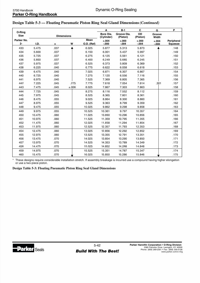
8/6/2019 Dynamic Oring Sealing
http://slidepdf.com/reader/full/dynamic-oring-sealing 42/49
Parker O-Ring Handbook 5700 Handbook Dynamic O-Ring Sealing
5-42
Build With The Best! Seals
Parker Hannifin Corporation • O-Ring Division
2360 Palumbo Drive, Lexington, KY 40509Phone: (859) 269-2351 • Fax : (859) 335-5128www.parker.com/o-ring
O-Ring
Size
Parker No.
2-
Dimensions
Mean
I.D. ± W O.D. (Ref)
A
Bore Dia.(Cylinder)
+.004-.000
B-1
Groove Dia.(Piston)
+.000-.004
C
OD(Piston)
+.000-.004
G
GrooveWidth
+.004-.000
P
PeripheralSqueeze
433 5.475 .037 6.025 5.877 5.313 5.873 .148434 5.600 .037 6.150 6.001 5.437 5.997 .149
435 5.725 .037 6.275 6.125 5.561 6.121 .150
436 5.850 .037 6.400 6.249 5.685 6.245 .151
437 5.975 .037 6.525 6.373 5.809 6.369 .152
438 6.225 .040 6.775 6.622 6.058 6.618 .153
439 6.475 .040 7.025 6.871 6.307 6.867 .154
440 6.725 .040 7.275 7.120 6.556 7.116 .155
441 6.975 .040 7.525 7.369 6.805 7.365 .156
442 7.225 .045 .275 7.775 7.618 7.054 7.614 .301 .157
443 7.475 .045 ±.006 8.025 7.867 7.303 7.863 .158
444 7.725 .045 8.275 8.116 7.552 8.112 .159
445 7.975 .045 8.525 8.365 7.801 8.361 .160
446 8.475 .055 9.025 8.864 8.300 8.860 .161447 8.975 .055 9.525 9.363 8.799 9.359 .162
448 9.475 .055 10.025 9.862 9.298 9.858 .163
449 9.975 .055 10.525 10.361 9.797 10.357 .164
450 10.475 .060 11.025 10.860 10.296 10.856 .165
451 10.975 .060 11.525 11.359 10.795 11.355 .166
452 11.475 .060 12.025 11.858 11.294 11.854 .167
453 11.975 .060 12.525 12.357 11.793 12.353 .168
454 12.475 .060 13.025 12.856 12.292 12.852 .169
455 12.975 .060 13.525 13.355 12.791 13.351 .170
456 13.475 .070 14.025 13.854 13.290 13.850 .171
457 13.975 .070 14.525 14.353 13.789 14.349 .172
458 14.475 .070 15.025 14.852 14.288 14.848 .173
459 14.975 .070 15.525 15.351 14.787 15.347 .174
460 15.475 .070 16.025 15.850 15.286 15.846 .175
* These designs require considerable installation stretch. If assembly breakage is incurred use a compound having higher elongationor use a two-piece piston.
Design Table 5-3 — Floating Pneumatic Piston Ring Seal Gland Dimensions (Continued)
Design Table 5-3: Floating Pneumatic Piston Ring Seal Gland Dimensions
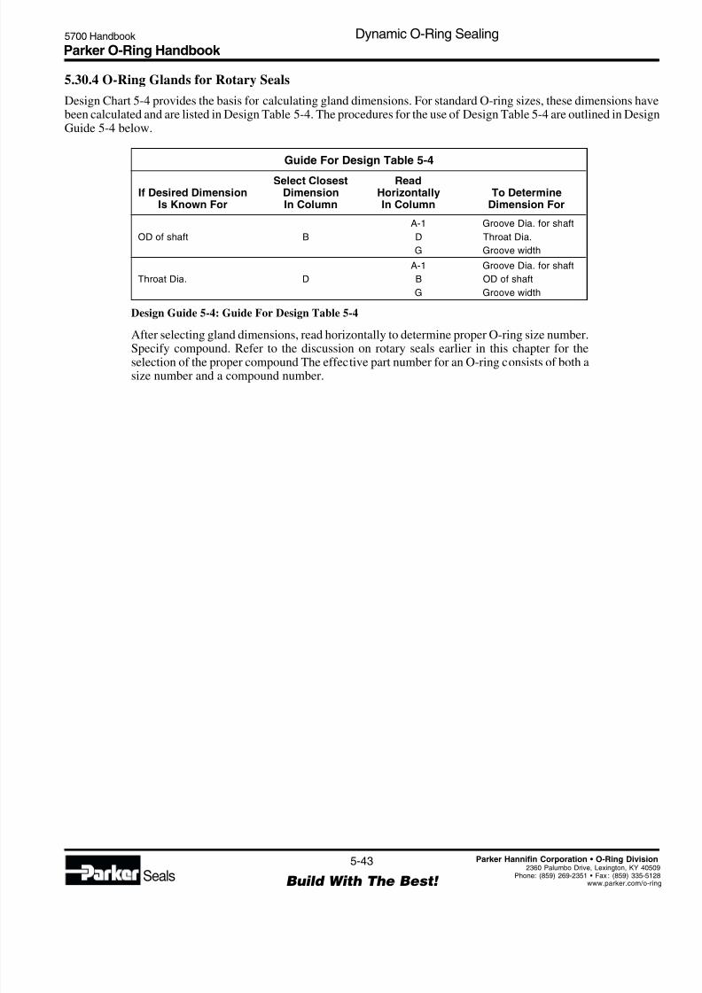
8/6/2019 Dynamic Oring Sealing
http://slidepdf.com/reader/full/dynamic-oring-sealing 43/49
Parker O-Ring Handbook 5700 Handbook Dynamic O-Ring Sealing
5-43
Build With The Best! Seals
Parker Hannifin Corporation • O-Ring Division
2360 Palumbo Drive, Lexington, KY 4050Phone: (859) 269-2351 • Fax : (859) 335-512www.parker.com/o-rin
5.30.4 O-Ring Glands for Rotary Seals
Design Chart 5-4 provides the basis for calculating gland dimensions. For standard O-ring sizes, these dimensions havebeen calculated and are listed in Design Table 5-4. The procedures for the use of Design Table 5-4 are outlined in DesignGuide 5-4 below.
Guide For Design Table 5-4
Select Closest ReadIf Desired Dimension Dimension Horizontally To Determine
Is Known For In Column In Column Dimension For
A-1 Groove Dia. for shaft
OD of shaft B D Throat Dia.
G Groove width
A-1 Groove Dia. for shaft
Throat Dia. D B OD of shaft
G Groove width
Design Guide 5-4: Guide For Design Table 5-4
After selecting gland dimensions, read horizontally to determine proper O-ring size number.
Specify compound. Refer to the discussion on rotary seals earlier in this chapter for theselection of the proper compound The effective part number for an O-ring consists of both asize number and a compound number.
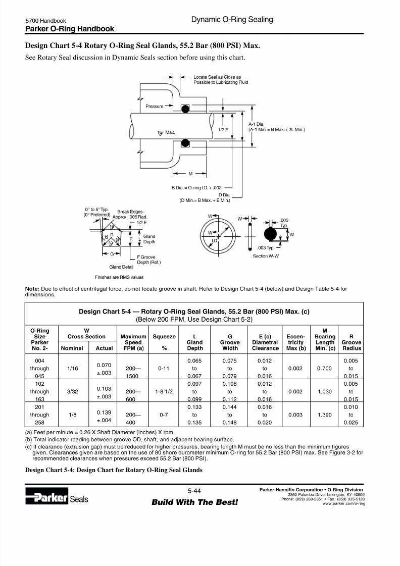
8/6/2019 Dynamic Oring Sealing
http://slidepdf.com/reader/full/dynamic-oring-sealing 44/49
Parker O-Ring Handbook 5700 Handbook Dynamic O-Ring Sealing
5-44
Build With The Best! Seals
Parker Hannifin Corporation • O-Ring Division
2360 Palumbo Drive, Lexington, KY 40509Phone: (859) 269-2351 • Fax : (859) 335-5128www.parker.com/o-ring
Design Chart 5-4 Rotary O-Ring Seal Glands, 55.2 Bar (800 PSI) Max.
See Rotary Seal discussion in Dynamic Seals section before using this chart.
Note: Due to effect of centrifugal force, do not locate groove in shaft. Refer to Design Chart 5-4 (below) and Design Table 5-4 for
dimensions.
O-Ring W MSize Cross Section Maximum Squeeze L G E (c) Eccen- Bearing R
Parker Speed Gland Groove Diametral tricity Length GrooveNo. 2- Nominal Actual FPM (a) % Depth Width Clearance Max (b) Min. (c) Radius
004 0.065 0.075 0.012 0.005
through 1/160.070
200— 0-11 to to to 0.002 0.700 to
045±.003
1500 0.067 0.079 0.016 0.015
102 0.097 0.108 0.012 0.005
through 3/320.103
200— 1-8 1/2 to to to 0.002 1.030 to
163 ±.003 600 0.099 0.112 0.016 0.015
201 0.133 0.144 0.016 0.010
through 1/8 0.139 200— 0-7 to to to 0.003 1.390 to
258 ±.004 400 0.135 0.148 0.020 0.025
(a) Feet per minute = 0.26 X Shaft Diameter (inches) X rpm.
(b) Total indicator reading between groove OD, shaft, and adjacent bearing surface.
(c) If clearance (extrusion gap) must be reduced for higher pressures, bearing length M must be no less than the minimum figuresgiven. Clearances given are based on the use of 80 shore durometer minimum O-ring for 55.2 Bar (800 PSI) max. See Figure 3-2 forrecommended clearances when pressures exceed 55.2 Bar (800 PSI).
Design Chart 5-4: Design Chart for Rotary O-Ring Seal Glands
Design Chart 5-4 — Rotary O-Ring Seal Glands, 55.2 Bar (800 PSI) Max. (c)
(Below 200 FPM, Use Design Chart 5-2)
Finishes are RMS values
Locate Seal as Close asPossible to Lubricating Fluid
Pressure
M
B Dia.= O-ring I.D. + .002
D Dia.(D Min.= B Max. + E Min.)
16 Max.1/2 E
Gland Detail
1/2 E
F L
G
R
16
3 2
323
2
0° to 5°Typ.(0° Preferred)
Break EdgesApprox. .005 Rad.
GlandDepth
F GrooveDepth (Ref.)
A-1 Dia.(A-1 Min. = B Max.+ 2L Min.)
.005Typ.
W
WW
W
I.D.
.003 Typ.
Section W-W

8/6/2019 Dynamic Oring Sealing
http://slidepdf.com/reader/full/dynamic-oring-sealing 45/49
Parker O-Ring Handbook 5700 Handbook Dynamic O-Ring Sealing
5-45
Build With The Best! Seals
Parker Hannifin Corporation • O-Ring Division
2360 Palumbo Drive, Lexington, KY 4050Phone: (859) 269-2351 • Fax : (859) 335-512www.parker.com/o-rin
Table 5-4 — Rotary O-Ring Seal Gland Dimensions
004 .070 .005 .210 .072 .202 .084
005 .101 .005 .241 .103 .233 .115
006 .114 .005 .254 .116 .246 .128
007 .145 .005 .285 .147 .277 .159
008 .176 .005 .316 .178 .308 .190
009 .208 .005 .348 .210 .340 .222
010 .239 .005 .379 .241 .371 .253
011 .301 .005 .441 .303 .433 .315
012 .364 .005 .504 .366 .496 .378
013 .426 .005 .566 .428 .558 .440
014 .489 .005 .629 .491 .621 .503
015 .551 .007 .691 .553 .683 .565
016 .614 .009 .754 .616 .746 .628
017 .676 .009 .816 .678 .808 .693018 .739 .009 .070 .879 .741 .871 .753 .075
019 .801 .009 ±.003 .941 .803 .933 .815
020 .864 .009 1.004 .866 .996 .878
021 .926 .009 1.066 .928 1.058 .940
022 .989 .010 1.129 .991 1.121 1.003
023 1.051 .010 1.191 1.053 1.183 1.065
024 1.114 .010 1.254 1.116 1.246 1.128
025 1.176 .011 1.316 1.178 1.308 1.190
026 1.239 .011 1.379 1.241 1.371 1.253
027 1.301 .011 1.441 1.303 1.433 1.315
028 1.364 .013 1.504 1.366 1.496 1.378
029 1.489 .013 1.629 1.491 1.621 1.503
030 1.614 .013 1.754 1.616 1.746 1.628
031 1.739 .015 1.879 1.741 1.871 1.753
032 1.864 .015 2.004 1.866 1.996 1.878
033 1.989 .018 2.129 1.991 2.121 2.003
034 2.114 .018 2.254 2.116 2.246 2.128
035 2.239 .018 2.379 2.241 2.371 2.253
036 2.364 .018 2.504 2.366 2.496 2.378
037 2.489 .018 2.629 2.491 2.621 2.503
038 2.614 .020 2.754 2.616 2.746 2.628
039 2.739 .020 2.879 2.741 2.871 2.753
040 2.864 .020 3.004 2.866 2.996 2.878
041 2.989 .024 3.129 2.991 3.121 3.003
042 3.239 .024 3.379 3.241 3.371 3.253043 3.489 .024 3.629 3.491 3.621 3.503
044 3.739 .027 3.879 3.741 3.871 3.753
045 3.989 .027 4.129 3.991 4.121 4.003
102 .049 .005 .255 .051 .245 .063
103 .081 .005 .103 .287 .083 .277 .095 .108
104 .112 .005 ±.003 .318 .114 .308 .126
105 .143 .005 .349 .145 .339 .157
106 .174 .005 .380 .176 .370 .188
O-Ring
Size
Parker No.
2-
Dimensions
Mean
I.D. ± W O.D. (Ref)
B
OD(Shaft)
+.000-.001
A-1
Groove Dia.(Gland)
+.003-.000
D
ThroatDia.
+.003-.000
G
GrooveWidth
+.004-.000
† For pressures over 55.2 Bar (800 PSI), consult Design Chart 5-4 and the design sections of this Handbook.
Design Table 5-4: Rotary O-Ring Seal Gland Dimensions
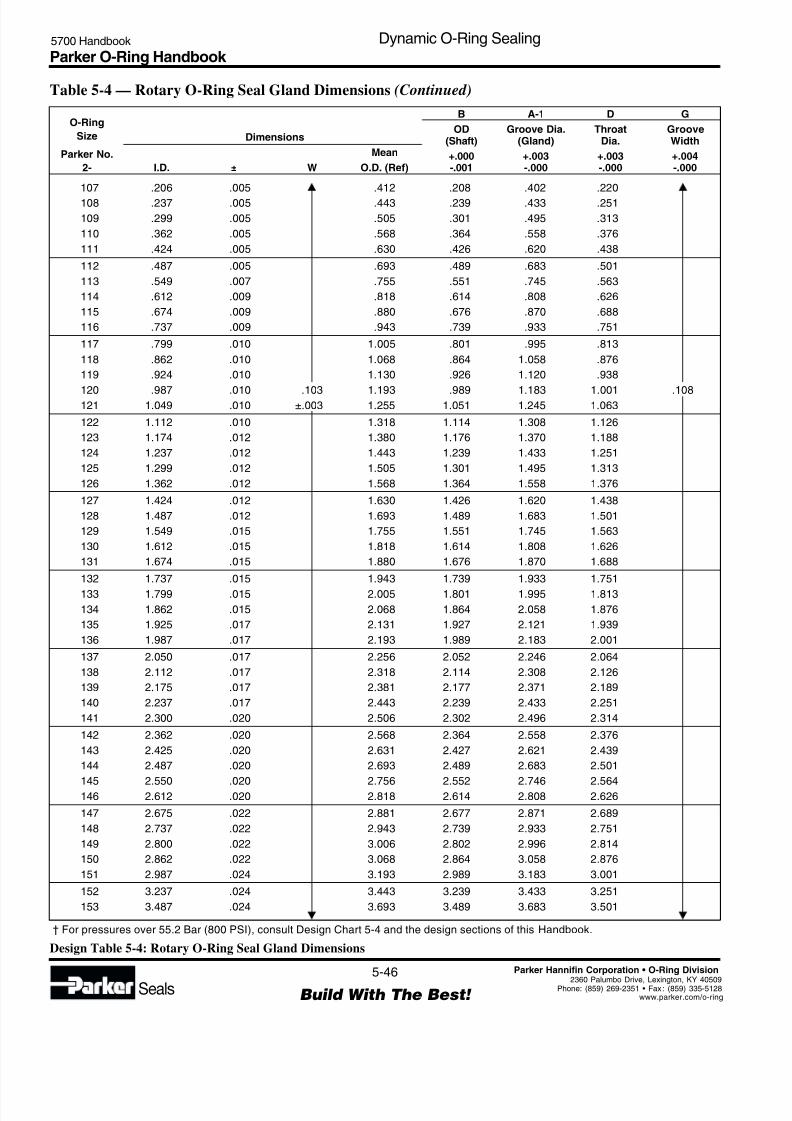
8/6/2019 Dynamic Oring Sealing
http://slidepdf.com/reader/full/dynamic-oring-sealing 46/49
Parker O-Ring Handbook 5700 Handbook Dynamic O-Ring Sealing
5-46
Build With The Best! Seals
Parker Hannifin Corporation • O-Ring Division
2360 Palumbo Drive, Lexington, KY 40509Phone: (859) 269-2351 • Fax : (859) 335-5128www.parker.com/o-ring
Table 5-4 — Rotary O-Ring Seal Gland Dimensions (Continued)
107 .206 .005 .412 .208 .402 .220
108 .237 .005 .443 .239 .433 .251
109 .299 .005 .505 .301 .495 .313
110 .362 .005 .568 .364 .558 .376
111 .424 .005 .630 .426 .620 .438
112 .487 .005 .693 .489 .683 .501
113 .549 .007 .755 .551 .745 .563
114 .612 .009 .818 .614 .808 .626
115 .674 .009 .880 .676 .870 .688
116 .737 .009 .943 .739 .933 .751
117 .799 .010 1.005 .801 .995 .813
118 .862 .010 1.068 .864 1.058 .876
119 .924 .010 1.130 .926 1.120 .938
120 .987 .010 .103 1.193 .989 1.183 1.001 .108121 1.049 .010 ±.003 1.255 1.051 1.245 1.063
122 1.112 .010 1.318 1.114 1.308 1.126
123 1.174 .012 1.380 1.176 1.370 1.188
124 1.237 .012 1.443 1.239 1.433 1.251
125 1.299 .012 1.505 1.301 1.495 1.313
126 1.362 .012 1.568 1.364 1.558 1.376
127 1.424 .012 1.630 1.426 1.620 1.438
128 1.487 .012 1.693 1.489 1.683 1.501
129 1.549 .015 1.755 1.551 1.745 1.563
130 1.612 .015 1.818 1.614 1.808 1.626
131 1.674 .015 1.880 1.676 1.870 1.688
132 1.737 .015 1.943 1.739 1.933 1.751
133 1.799 .015 2.005 1.801 1.995 1.813
134 1.862 .015 2.068 1.864 2.058 1.876
135 1.925 .017 2.131 1.927 2.121 1.939
136 1.987 .017 2.193 1.989 2.183 2.001
137 2.050 .017 2.256 2.052 2.246 2.064
138 2.112 .017 2.318 2.114 2.308 2.126
139 2.175 .017 2.381 2.177 2.371 2.189
140 2.237 .017 2.443 2.239 2.433 2.251
141 2.300 .020 2.506 2.302 2.496 2.314
142 2.362 .020 2.568 2.364 2.558 2.376
143 2.425 .020 2.631 2.427 2.621 2.439
144 2.487 .020 2.693 2.489 2.683 2.501
145 2.550 .020 2.756 2.552 2.746 2.564146 2.612 .020 2.818 2.614 2.808 2.626
147 2.675 .022 2.881 2.677 2.871 2.689
148 2.737 .022 2.943 2.739 2.933 2.751
149 2.800 .022 3.006 2.802 2.996 2.814
150 2.862 .022 3.068 2.864 3.058 2.876
151 2.987 .024 3.193 2.989 3.183 3.001
152 3.237 .024 3.443 3.239 3.433 3.251
153 3.487 .024 3.693 3.489 3.683 3.501
O-Ring
Size
Parker No.
2-
Dimensions
Mean
I.D. ± W O.D. (Ref)
B
OD(Shaft)
+.000-.001
A-1
Groove Dia.(Gland)
+.003-.000
D
ThroatDia.
+.003-.000
G
GrooveWidth
+.004-.000
† For pressures over 55.2 Bar (800 PSI), consult Design Chart 5-4 and the design sections of this Handbook.
Design Table 5-4: Rotary O-Ring Seal Gland Dimensions

8/6/2019 Dynamic Oring Sealing
http://slidepdf.com/reader/full/dynamic-oring-sealing 47/49
Parker O-Ring Handbook 5700 Handbook Dynamic O-Ring Sealing
5-47
Build With The Best! Seals
Parker Hannifin Corporation • O-Ring Division
2360 Palumbo Drive, Lexington, KY 4050Phone: (859) 269-2351 • Fax : (859) 335-512www.parker.com/o-rin
154 3.737 .028 3.943 3.739 3.933 3.751
155 3.987 .028 4.193 3.989 4.183 4.001
156 4.237 .030 4.443 4.239 4.433 4.251
157 4.487 .030 .103 4.693 4.489 4.683 4.501 .108
158 4.737 .030 ±.003 4.943 4.739 4.933 4.751
159 4.987 .035 5.193 4.989 5.183 5.001
160 5.237 .035 5.443 5.239 5.433 5.251
161 5.487 .035 5.693 5.489 5.683 5.501
162 5.737 .035 5.943 5.739 5.933 5.751
163 5.987 .035 6.193 5.989 6.183 6.001
201 .171 .005 .449 .173 .439 .189
202 .234 .005 .512 .236 .502 .252
203 .296 .005 .574 .298 .564 .314
204 .359 .005 .637 .361 .627 .377205 .421 .005 .699 .423 .689 .439
206 .484 .005 .762 .486 .752 .502
207 .546 .007 .824 .548 .814 .564
208 .609 .009 .887 .611 .877 .627
209 .671 .009 .949 .673 .939 .689
210 .734 .010 1.012 .736 1.002 .752
211 .796 .010 1.074 .798 1.064 .814
212 .859 .010 1.137 .861 1.127 .877
213 .921 .010 1.199 .923 1.189 .939
214 .984 .010 .139 1.262 .986 1.252 1.002 .144
215 1.046 .010 ±.004 1.324 1.048 1.314 1.064
216 1.109 .012 1.387 1.111 1.377 1.127
217 1.171 .012 1.449 1.173 1.439 1.189
218 1.234 .012 1.512 1.236 1.502 1.252
219 1.296 .012 1.574 1.298 1.564 1.314
220 1.359 .012 1.637 1.361 1.627 1.377
221 1.421 .012 1.699 1.423 1.689 1.439
222 1.484 .015 1.762 1.486 1.752 1.502
223 1.609 .015 1.887 1.611 1.877 1.627
224 1.734 .015 2.012 1.736 2.002 1.752
225 1.859 .018 2.137 1.861 2.127 1.877
226 1.984 .018 2.262 1.986 2.252 2.002
227 2.109 .018 2.387 2.111 2.377 2.127
228 2.234 .020 2.512 2.236 2.502 2.252
229 2.359 .020 2.637 2.361 2.627 2.377230 2.484 .020 2.762 2.486 2.752 2.502
231 2.609 .020 2.887 2.611 2.877 2.627
232 2.734 .024 3.012 2.736 3.002 2.752
233 2.859 .024 3.137 2.861 3.127 2.877
234 2.984 .024 3.262 2.986 3.252 3.002
235 3.109 .024 3.387 3.111 3.377 3.127
236 3.234 .024 3.512 3.236 3.502 3.252
237 3.359 .024 3.637 3.361 3.627 3.377
O-Ring
Size
Parker No.
2-
Dimensions
Mean
I.D. ± W O.D. (Ref)
B
OD(Shaft)
+.000-.001
A-1
Groove Dia.(Gland)
+.003-.000
D
ThroatDia.
+.003-.000
G
GrooveWidth
+.004-.000
† For pressures over 55.2 Bar (800 PSI), consult Design Chart 5-4 and the design sections of this Handbook.
Table 5-4 — Rotary O-Ring Seal Gland Dimensions (Continued)
Design Table 5-4: Rotary O-Ring Seal Gland Dimensions
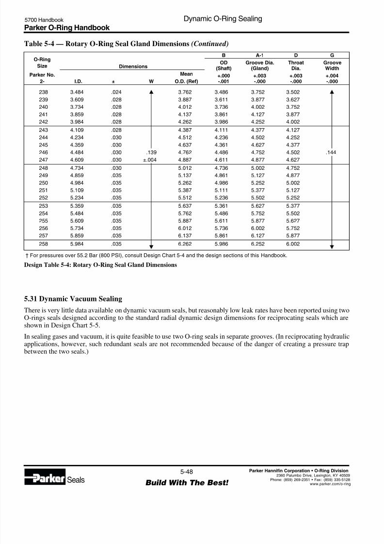
8/6/2019 Dynamic Oring Sealing
http://slidepdf.com/reader/full/dynamic-oring-sealing 48/49
Parker O-Ring Handbook 5700 Handbook Dynamic O-Ring Sealing
5-48
Build With The Best! Seals
Parker Hannifin Corporation • O-Ring Division
2360 Palumbo Drive, Lexington, KY 40509Phone: (859) 269-2351 • Fax : (859) 335-5128www.parker.com/o-ring
O-Ring
Size
Parker No.
2-
Dimensions
Mean
I.D. ± W O.D. (Ref)
B
OD(Shaft)
+.000-.001
A-1
Groove Dia.(Gland)
+.003-.000
D
ThroatDia.
+.003-.000
G
GrooveWidth
+.004-.000
† For pressures over 55.2 Bar (800 PSI), consult Design Chart 5-4 and the design sections of this Handbook.
238 3.484 .024 3.762 3.486 3.752 3.502
239 3.609 .028 3.887 3.611 3.877 3.627
240 3.734 .028 4.012 3.736 4.002 3.752
241 3.859 .028 4.137 3.861 4.127 3.877
242 3.984 .028 4.262 3.986 4.252 4.002
243 4.109 .028 4.387 4.111 4.377 4.127
244 4.234 .030 4.512 4.236 4.502 4.252
245 4.359 .030 4.637 4.361 4.627 4.377
246 4.484 .030 .139 4.762 4.486 4.752 4.502 .144
247 4.609 .030 ±.004 4.887 4.611 4.877 4.627
248 4.734 .030 5.012 4.736 5.002 4.752
249 4.859 .035 5.137 4.861 5.127 4.877
250 4.984 .035 5.262 4.986 5.252 5.002
251 5.109 .035 5.387 5.111 5.377 5.127252 5.234 .035 5.512 5.236 5.502 5.252
253 5.359 .035 5.637 5.361 5.627 5.377
254 5.484 .035 5.762 5.486 5.752 5.502
255 5.609 .035 5.887 5.611 5.877 5.627
256 5.734 .035 6.012 5.736 6.002 5.752
257 5.859 .035 6.137 5.861 6.127 5.877
258 5.984 .035 6.262 5.986 6.252 6.002
Table 5-4 — Rotary O-Ring Seal Gland Dimensions (Continued)
Design Table 5-4: Rotary O-Ring Seal Gland Dimensions
5.31 Dynamic Vacuum Sealing
There is very little data available on dynamic vacuum seals, but reasonably low leak rates have been reported using twoO-rings seals designed according to the standard radial dynamic design dimensions for reciprocating seals which areshown in Design Chart 5-5.
In sealing gases and vacuum, it is quite feasible to use two O-ring seals in separate grooves. (In reciprocating hydraulicapplications, however, such redundant seals are not recommended because of the danger of creating a pressure trapbetween the two seals.)
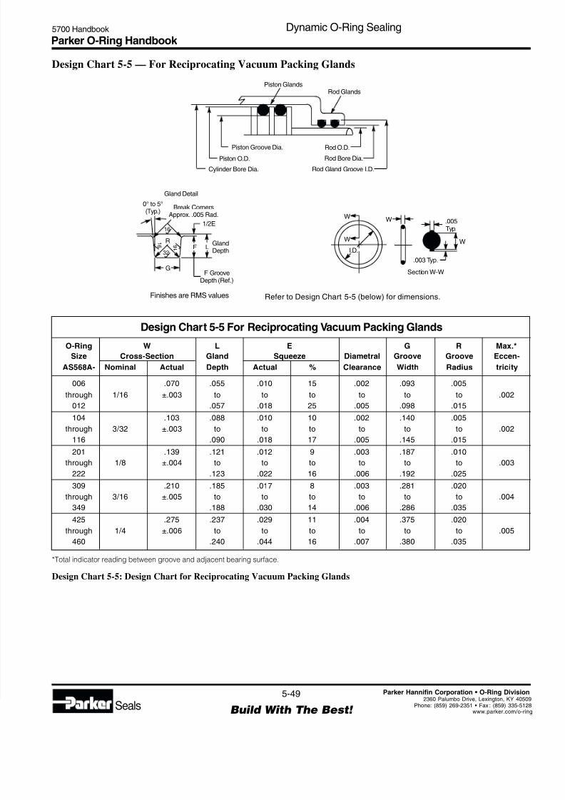
8/6/2019 Dynamic Oring Sealing
http://slidepdf.com/reader/full/dynamic-oring-sealing 49/49
Parker O-Ring Handbook 5700 Handbook Dynamic O-Ring Sealing
Design Chart 5-5 — For Reciprocating Vacuum Packing Glands
Refer to Design Chart 5-5 (below) for dimensions.
O-Ring W L E G R Max.*
Size Cross-Section Gland Squeeze Diametral Groove Groove Eccen-
AS568A- Nominal Actual Depth Actual % Clearance Width Radius tricity
006 .070 .055 .010 15 .002 .093 .005
through 1/16 ±.003 to to to to to to .002
012 .057 .018 25 .005 .098 .015
104 .103 .088 .010 10 .002 .140 .005through 3/32 ±.003 to to to to to to .002
116 .090 .018 17 .005 .145 .015
201 .139 .121 .012 9 .003 .187 .010
through 1/8 ±.004 to to to to to to .003
222 .123 .022 16 .006 .192 .025
309 .210 .185 .017 8 .003 .281 .020
through 3/16 ±.005 to to to to to to .004
349 .188 .030 14 .006 .286 .035
425 .275 .237 .029 11 .004 .375 .020
through 1/4 ±.006 to to to to to to .005
460 .240 .044 16 .007 .380 .035
Design Chart 5-5 For Reciprocating Vacuum Packing Glands
*Total indicator reading between groove and adjacent bearing surface.
Design Chart 5-5: Design Chart for Reciprocating Vacuum Packing Glands
Piston GlandsRod Glands
Rod O.D.Piston Groove Dia.
Rod Bore Dia.Piston O.D.
Rod Gland Groove I.D.Cylinder Bore Dia.
Gland Detail
1/2E
F L
G
R
16
1 6
321
6
0° to 5°(Typ.)
Break CornersApprox. .005 Rad.
GlandDepth
F Groove
Depth (Ref.)
.005Typ.
W
WW
W
I.D.
.003 Typ.
Section W-W
Finishes are RMS values