dynamic performance of flettner rotors with … ship/tsfp7... · dynamic performance of flettner...
TRANSCRIPT

1
DYNAMIC PERFORMANCE OF FLETTNER ROTORS WITH AND WITHOUT THOM
DISCS
T. J. Craft, H. Iacovides and B. E. Launder
Turbulence Mechanics Group, School of MACE
University of Manchester, Manchester, UK.
ABSTRACT
The paper presents U-RANS simulations for 3-dimen-
sional flow past a rotating cylinder for a range of Reynolds
numbers and rotation rates relevant to the performance of
ships propelled by Flettner rotors in place of sails.
Comparisons are first drawn with existing LES data of similar
flows at much lower Reynolds numbers. Thereafter the
performance is examined for values of Re within the probable
range of actual rotor operating conditions, including an
exploration of the effect of adding discs mounted along the
length of the cylinder which Thom (1934) had suggested led
to improved performance at high spin rates.
INTRODUCTION
In the early Twenties collaborative work by Prandtl (1925)
and Anton Flettner led to the conclusion that the Magnus
effect1 could be exploited to provide an efficient and effective
way of propelling ships. In demonstration, Flettner replaced
the sails on two barquentine ships, by twin vertical rotors. One
of the ships, originally the Buckau but re-named, following
conversion, the Baden Baden thereafter crossed the Atlantic,
Fig. 1. The rotors, which became immediately known as
Flettner rotors, had numerous advantages over conventional
wind-driven propulsion, being only one quarter of the weight
of the masts, sails and rigging they replaced and permitting the
vessel to make more rapid progress over a wide range of wind
speeds and directions than conventional sails. Further
commercial development did not take place, however, due to
the grave financial depression of the late 1920’s and to the
emergence of diesel-powered craft (and the plentiful supply
and consequent low price of diesel fuel).
Now, in the 21st Century, with fuel prices having soared
and a growing recognition of the necessity to slash CO2
emissions urgently, the potential of the Flettner rotor is again
being seriously examined. Enercon, the wind-turbine
company, has commissioned and brought into service in late
2010 a vessel for delivering the shafts and rotors of its
turbines that has four Flettner rotors as its primary source of
propulsion. Even more ambitious (Salter et al., 2008) is a
1 in which a spinning cylinder past which an external stream is
flowing receives a lateral thrust due to the lower pressure on the side
of the cylinder where the cylinder’s motion is in the same direction as the streaming flow.
proposal to build a fleet of 1500 unmanned, radio-controlled
craft driven by Flettner rotors. These would eject vertically a
fine mist of seawater and, on the evaporation of the water,
would leave ultra-fine salt grains, a proportion of which would
be lofted to form additional cloud condensation nuclei thus
brightening the low-level marine stratus clouds to reflect an
increased proportion of incident sunlight. The above authors
believe that such a fleet would be sufficient to reduce the
sunlight incident upon the earth by roughly 2% which should
reduce global mean temperatures to those prevailing at the
start of the industrial revolution. In fact, Salter et al. (2008)
proposed that discs should be added along the length of the
spinning cylinders since Thom (1934) had reported that this
modification significantly increased the attainable lift
coefficient for normalised rotor-spin velocities, Ω≡Uspin/Uwind,
greater than 4. Further experiments with a bare rotor have
been reported by Reid (1924) with a view to possible use on
aircraft and by Bergeson & Greenwald (1985) for a rotor
mounted on a test vessel.
More than 75 years on from Thom’s experiments,
computational studies of the spinning cylinder seem the most
productive route to explore aerodynamic aspects relating to
the performance of Flettner rotors with or without discs. There
have been several impressive studies of two-dimensional flow
around a smooth cylinder for laminar flow up to Reynolds
numbers of a few hundred and Ω as high as 12 (Stojkovic et
Figure 1. Photograph of the original Flettner rotor ship.
2
al., 2002; Mittal & Kumar, 2003; Padrino & Joseph, 2006; El
Akoury et al., 2009). These have shown that for normalized
spin rates much in excess of 2 the conventional Karman vortex
is suppressed, the lift coefficient rises strongly with spin rate
but that large amplitude pulsations on the rotor occur over a
narrow range of rotation rates for Ω between 3.5 and 5.5, the
precise range depending upon Reynolds number, El Akoury et
al. (2009). These last authors also looked at 3D simulations
but apparently only for Ω up to 0.5. Very recently Karabelas
(2010) has reported an LES study at Re = 140,000 (which we
note is still many times less than that at which sea-going
Flettner-rotor vessels would operate). That study found no
such periodicities in drag or lift (once the spin ratio was high
enough to suppress the conventional Karman vortex) but the
maximum value of Ω was only 2.0 so this result was not in
conflict with the previous laminar studies at lower Re.
In a previous publication, using an unsteady RANS
strategy, the present authors (see Latham et al., 2011) have
found that for a Reynolds number of 8x10⁵ no periodic forcing
occurred for Ω equal to 3.0 and 5.0. There were, however,
small irregular variations associated with temporal variations
in the shed vortices. The addition of discs brought no overall
enhancement of lift coefficient, but they did remove the slight
temporal irregularity noted above for the smooth cylinder.
The above results left a number of questions unresolved
some of which the present paper has endeavoured to answer.
The first is whether the instabilities noted in the 2D laminar
flow results also appeared in turbulent flow. The second issue
is the apparently contradictory findings of Thom’s
experiments and the authors’ earlier CFD results of the
effectiveness of Thom discs. Comparisons are also drawn with
the bare cylinder LES study of Karabelas (2010) to assess the
likely adequacy of the closure modelling included within the
present U-RANS computations. The sections below first
summarize the computational and turbulence models applied,
before presenting the current results and finally drawing
conclusions.
NUMERICAL MODEL
Three-dimensional, time-dependent computations have
been carried out with the in-house flow solver STREAM. It is
a finite-volume, general-geometry code with a collocated grid,
using Cartesian velocity decomposition. The pressure is
obtained through the SIMPLE algorithm. The bounded high-
order UMIST scheme, Lien and Leschziner (1994), is used for
the discretisation of convection and the Crank-Nicolson
scheme for temporal discretisation. Two versions of this code
have been employed, one using a single block and one
employing a multi-block grid. In the single block version, the
rotating cylinder is placed at the centre of a cylindrical polar
mesh extending to a radius 10 times that of the cylinder. The
multi-block arrangement allows for a solution domain which
downstream of the cylinder has a rectangular shape and it is
longer than the upstream section. In both approaches a fixed
cross-flow velocity is specified along the upstream boundary,
with zero-gradient (in the main flow direction) conditions
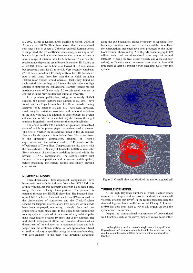
along the exit boundaries. Either symmetry or repeating flow
boundary conditions were imposed in the axial direction. Here
the computations presented have been produced by the multi-
block version, shown in Fig. 2, with grids containing up to 0.9
million cells, and non-dimensional time steps of around
0.01U/R (U being the free-stream velocity and R the cylinder
radius), sufficiently small to ensure there were at least 600
time steps covering a typical vortex shedding cycle from the
cylinder.
TURBULENCE MODEL
At the high Reynolds numbers at which Flettner rotors
operate, it is impractical to resolve in detail the near-wall
viscosity-affected sub-layer2. In the results presented here the
standard log-law based wall-function of Chieng & Launder
(1980) has thus been used to cover this region on both the
cylinder and disc surfaces.
Despite the computational convenience of conventional
wall-functions such as the above, they are known to be rather
2 Although for a small section of a single rotor a fine-grid “low-
Reynolds-number” treatment would be feasible that would not be the
case for a complete rotor still less for several rotors mounted close together.
Figure 2. Overall view and detail of the non-orthogonal grid

3
unreliable in capturing features such as significant streamwise
pressure gradients, or the considerable skewing that is likely
to occur across the very near-wall region, particularly when
Thom discs are added. Future calculations may, therefore, test
the effect of employing more advanced wall-functions such as
the Analytical Wall-Function (AWF) approach, described in
Craft et al. (2002) and more recently extended to three-
dimensional flow where the velocity vector parallel to the
wall undergoes considerable skewing across the viscosity-
affected sublayer (Zacharos, 2010; Craft et al., 2008).
The sublayer treatment above, which is applied to a thin
region close to all rigid surfaces, can be matched to any
desired turbulence model for the remainder of the flow. The
majority of the present results have been obtained with a form
of k-ε linear eddy-viscosity model containing a near-wall
length-scale control to prevent excessive length scales arising
in adverse-pressure-gradient regions (Yap, 1987), although in
the present computations with a wall-function applied at the
near-wall node this term is unlikely to have a particularly
large effect on the solution.
Further results have been obtained with the two-
component-limit (TCL) stress-transport closure3 of Craft et al.
(1996), the most advanced RANS model used by our group,
that has been successfully applied to a wide range of
challenging 3D turbulent flows near walls (e.g. Craft &
Launder, 2001). This model overall clearly outperforms eddy-
viscosity models (EVMs), though for the present cases, within
a U-RANS solver where the resulting unsteadiness may
contribute a major proportion of the momentum transport, the
differences are relatively small. Consequently, because of the
lower computational and core demands, most results have
been obtained with the simpler EVM.
PRESENTATION AND DISCUSSION OF RESULTS
The first computations were made in 2D mode at
Reynolds numbers below 500 to verify that the present
simulations accorded closely with those reported earlier by
those examining laminar flows. Particular attention was given
to the study of Mittal & Kumar (2003) at Re=200. Virtually
complete agreement with the effects of increasing the spin
ratio were found: the suppression of the Karman vortex
shedding at Ω=3.0, the appearance of large amplitude
fluctuations for Ω=4.4 and their disappearance by Ω=5.0
giving a lift coefficient CL in excess of 25. These have been
reported in detail in Craft et al. (2010) and are not re-presented
here.
Next, in 3D mode, attention has been given to the cases at
Re = 1.4x10⁵ examined via LES by Karabelas (2010), shown
in Figs. 3-5. The modification of the time-averaged streakline
pattern around the cylinder (from the symmetric pattern for
Ω=0, not shown) for Ω=1 and 2 is evident in Fig. 3 where the
3 A model which incorporates constraints so that, as the wall is
approached, turbulent fluctuations normal to the wall vanish faster
than wall-parallel components (as required by continuity). Thus, in the limit the modelled turbulent stresses reach the two-component limit.
cylinder spins anticlockwise. At the lower spin rate two
separated flow zones are still present, though clearly distorted
by the cylinder rotation. At the higher spin rate the accord
between the LES and the TCL U-RANS results is still broadly
satisfactory though the lower of the separation zones, that the
LES data suggest is entirely suppressed, is still evident for the
U-RANS computation. The progressive modification in flow
pattern shown in Fig. 3 leads to an increase in lift coefficient
with spin ratio shown in Fig. 4a. The overall behaviour is
reproduced slightly better with the TCL model than the k-ε
EVM though the latter better captures the LES level of lift at
the highest spin rate. The TCL scheme also captures the drag
coefficient more closely, Fig. 4b, though neither model is
particularly close at Ω=1. The reason for this can be inferred
from Fig. 5 which shows the pressure variation around the
cylinder. Evidently, for 135°<θ<270° (covering most of the
downwind face of the cylinder) the static pressure is higher
than for the LES data resulting in a lower drag coefficient. For
no rotation, separation occurs earlier with the TCL model than
with the EVM and this accords well with the LES behaviour.
It is noted, in passing, that the experimental data at Re=6x10⁴
of Aoki & Ito (2001) shows rather closer agreement to TCL
drag coefficients than do the LES data. At the highest spin
rate, however, the EVM computations reproduce the more
rapid fall in pressure from 0-90° indicated by the LES data
and this is crucial to the superior lift coefficient at this spin
ratio seen in Fig. 4a.
A comparison over a wider range of spin ratios and Re
appears in Figs. 6 and 7. Included in the figures are the early
data of Reid (1924) and the Bergeson & Greenwald (1985)
Figure 3. Comparison of mean streaklines created by flow past
a spinning cylinder. Left: LES data of Karabelas; Right:
Present U-RANS. Top Ω=1; Bottom Ω=2.

4
data. There is generally good accord among the lift
coefficients reported from different sources which exhibit
initially a virtually linear growth in CL with Ω but then, for
spin ratios greater than 3, a more gradual rise. This pattern is
well captured by the U-RANS computations (obtained with
the EVM). There is, however, a striking difference in the drag
coefficient, Fig. 7, where the Reid data, after initially falling
with Ω, show a marked rise. Bergeson & Greenwald (1985) do
not report CD variations but the U-RANS computations are, as
noted above, in reasonable agreement with the Karabelas
(2010) LES data. At the high Reynolds numbers here
considered the main contribution to the drag is associated with
the imbalance of static pressure on the upstream and
downstream faces of the cylinder rather than wall friction. The
fact that the Reid data of CL are slightly lower than the other
data while CD are higher perhaps suggests a relatively small
error in determining the angular orientation.
Finally, the effect of adding discs in the manner of Thom
is considered. Only a single geometric arrangement has been
examined. The axial spacing, h, between adjacent discs equals
the cylinder diameter, d, while the discs themselves are of
diameter 2d. Spinning discs are known to generate locally a
complex flow field with a centrifugally-driven radial outflow
adjacent to the disc (the Ekman layer). It is thus hard to
foresee what effect the interaction of this flow with the
apparent wind will have on the distribution of static pressure
around the cylinder (which, of course, largely determines the
lift and drag coefficients). The computed values of these
parameters for the case with discs is also included in Figs. 6
and 7. At low rotation speeds there is scarcely any difference
in lift coefficient while the drag coefficient for the case with
discs is slightly greater than for the bare cylinder. However,
for spin ratios of 5 and above the drag falls to or below that for
the bare cylinder while the lift increases with Ω rather faster
(a)
(b)
Figure 4. Predicted mean lift (a) and drag (b) coefficients for
rotating cylinder at Re=1.4x10⁵, compared with the LES data
of Karabelas (2010).
Figure 5. Predicted pressure coefficients around rotating and
non-rotating cylinder at Re=1.4x10⁵, compared to the LES
data of Karabelas (2010).
Figure 6. Predicted and measured mean lift coefficients for
rotating cylinders with and without Thom discs.

5
than for the bare cylinder. Indeed, for Ω=8 the lift coefficient
is 8% greater while the drag is less than half that for a bare
cylinder. The detailed role of the discs on the flow dynamics
requires deeper investigation than we have so far been able to
provide. On the one hand, Fig. 8 shows that for moderate spin
rates (Ω=3 or 5) the discs smooth out the temporal
unsteadiness in lift (and drag, not shown). For Ω=5, Fig. 9
provides a snapshot of the flow around the cylinder for the
two cases, i.e. with and without discs, using the Q-Criterion to
distinguish the flow patterns. Without discs the flow is
strongly unsteady while, with the discs added, the flow in the
vicinity of the cylinder is invariant with time with just a mild
temporal fluctuation visible in the tails of the horseshoe
vortices created on the upstream side by the disc-cylinder
intersections. However, as Fig. 8 makes clear, at higher spin
rates, the discs fail to cause any significant suppression of the
fluctuations.
Finally, it is noted that the boundary conditions applied at
the upper and lower ends of the domain (z=h and 0) can have a
significant effect on the results in the case where discs are
present. Most of the computations have been run assuming (as
remarked earlier) periodic boundary conditions on these
planes. However, for Ω=6, tests were also made with
symmetry boundary conditions applied instead. For the bare
cylinder the two runs lead to sensibly the same randomly
fluctuating behaviour. When discs are present, however, the
application of symmetry boundary conditions (for radii greater
than that of the discs) entirely suppresses the fluctuations. For
an actual multi-disc rotor neither boundary condition is
correct. Indeed, the only sure route is to include the whole
rotor within the computation because clearly (just above the
top of the rotor) the free passage of the wind and (beneath the
lower end of the rotor) the deck and superstructure will each
have an effect on the rotor dynamics.
CONCLUSIONS
The paper has reported U-RANS computations of the flow
past a section of a spinning rotor with a view to comparing
results with earlier studies at low Reynolds number and,
principally, to assessing the likely performance of a Flettner
rotor over a range of conditions. First, regarding laminar flow,
it is noted that our earlier 2-dimensional simulations have
confirmed the large-amplitude, low-frequency periodicities
previously reported by others over a narrow range of rotation
rates.
In turbulent flow, no such large amplitude periodicities
have been found, however. Close agreement has been obtained
with the LES lift and drag coefficients of Karabelas (2010)
which is encouraging since the cost of a U-RANS
computation is at least an order of magnitude less than for
LES. Turning to the rotor performance at the high Reynolds
numbers encountered in actual Flettner rotors, for a bare
cylinder very satisfactory accord with the lift coefficients
reported in two sets of experimental data for spin ratios up to 6
has been obtained. The effect of adding discs at intervals
along the spinning cylinder as advocated by Thom (1934) led,
at low spin rates, to negligible change in lift coefficient and
modestly higher drag coefficient. For spin ratios above 5,
however, the lift coefficient is higher by up to 10%. However,
this is a markedly smaller improvement than reported by
Thom, but the discs in his experiments were of larger diameter
relative to the cylinder and with closer spacing, which may
possibly account for the greater augmentation of lift.
While the present U-RANS study has found encouraging
agreement with the available experimental and LES data, it
would be desirable, before embarking on an examination of
further practical issues and fundamental aspects of Flettner-
rotor performance, to embed a more generally applicable wall
treatment (such as the AWF scheme that allows vector
skewing within the viscous sublayer and an effective sublayer
thickness sensitive to locally prevailing conditions, Craft et
al., 2008) in place of the relatively rudimentary wall functions
currently adopted.
Figure 7. Predicted and measured mean drag coefficients for
rotating cylinders with and without Thom discs.
Figure 8. Predicted lift-coefficient histories for rotating
cylinders with and without Thom discs.

6
REFERENCES
Aoki, K. and Ito, T., 2001, Flow characteristics around a
rotating cylinder, Proc. School of Eng’ng, Tokai Univ., 26, 29-
34.
Bergeson, L. and Greenwald, C. K., 1985, Sail assist
developments 1979-85, J. Wind Eng’ng & Indust. Aerodyn.,
19, 45-114.
Chieng, C. C. and Launder, B. E., 1980, On the
calculation of turbulent heat transfer downstream from an
abrupt pipe expansion, Numerical Heat Transfer, 3, 189-207.
Craft, T. J., Gerasimov, A. V., Iacovides, H. and Launder,
B. E., 2002, Progress in the generalization of wall-function
treatments, Int. J. Heat & Fluid Flow, 23, 148-160.
Craft, T. J., Iacovides, H. and Launder, B. E., 2010,
Computational modelling of Flettner-rotor performance with
and without Thom discs, Proc. 7th Conf. on Eng’g Turbulence
Modelling & Meas., Marseilles.
Craft, T. J., Iacovides, H., Launder, B. E. and Zacharos,
A., 2008, Some swirling-flow challenges for turbulent flow
CFD, Flow Turbulence & Combustion, 80, 419-434.
Craft, T. J., Ince, N. Z., and Launder, B. E., 1996, Recent
developments in second-moment closure for buoyancy-
affected flows, Dynamics of Atmospheres and Oceans, 23, 99-
114.
Craft, T. J. and Launder, B. E., 2001, Principles and
performance of TCL-based second-moment closures, Flow
Turbulence & Combustion, 66, 253-272.
El Akoury, R., Martinat, G., Braza, M., Perrin, R., Hoarau,
Y., Harran, G. and Ruiz, D., 2009, Successive steps of 2D and
3D transition in the flow past a rotating cylinder at moderate
Reynolds numbers, in IUTAM Symp on Unsteady Separated
Flows & their Control (M. Braza & K. Hourigan, Eds),
IUTAM Book Series 14, Springer.
Karabelas, S. J., 2010, Large-eddy simulation of turbulent
flow past a rotating cylinder, Int J. Heat & Fluid Flow, 31,
518-527.
Latham, J., et al., 2011, Marine cloud brightening, Phil
Trans Roy. Soc. (To appear).
Lien, F-S. and Leschziner, M. A., 1994, Upstream
monotonic interpolation for scalar transport with application
to complex turbulent flows, Int. J. Num. Meth. in Fluids, 19,
527–548.
Mittal, S. and Kumar, B., 2003, Flow past a rotating
cylinder, J. Fluid Mech., 476, 303-334.
Padrino, J. C. and Joseph, D. D., 2006, Flow past a
rotating cylinder, J. Fluid Mech., 476, 191-223.
Prandtl, L., 1925, The Magnus effect and wind-powered
ships, Naturwissenschaften, 13, 1787-1806.
Reid, E. G., 1924, Tests of rotating cylinders, NACA TN
209.
Salter, T., Sortino, G. and Latham, J., 2008, Sea-going
hardware for the cloud-albedo method of reversing global
warming, Phil Trans Roy Soc., 3666A, 3989-4006.
Stojkovic, D., Breuer, M. and Durst, F., 2002, Effects of
high rotation on the laminar flow around a circular cylinder,
Phys. Fluids, 14, 3160-3178.
Thom, A., 1934, Effects of discs on the air forces on a
rotating cylinder, Aero. Res. Counc. R&M 1623.
Yap, C. R., 1987, Turbulent heat and momentum transfer
in recirculating and impinging flows, PhD Thesis, Faculty of
Technology, University of Manchester.
Zacharos, A., 2010, The use of unsteady RANS in the
computation of 3-dimensiional flow in rotating cavities, PhD
Thesis, School of MACE, University of Manchester.
Bare Cylinder Cylinder with Thom Discs
Figure 9. Instantaneous snapshot of Q-criterion isosurface for flow around a cylinder with and without Thom discs at Ω=5;
Re=8x10⁵.