dynamic programming guide - subwoofer filter programming guide - subwoofer filter.pdf · dynamic...
TRANSCRIPT
© Anadigm 2004 Page 1 of 29 Document revision 1.0.1, 25th February 2004 Doc No. SK01SUBW-U001
~ Dynamic Programming Starter Guide – Subwoofer Filter Rev: 1.0.1
Date: 25th February 2004
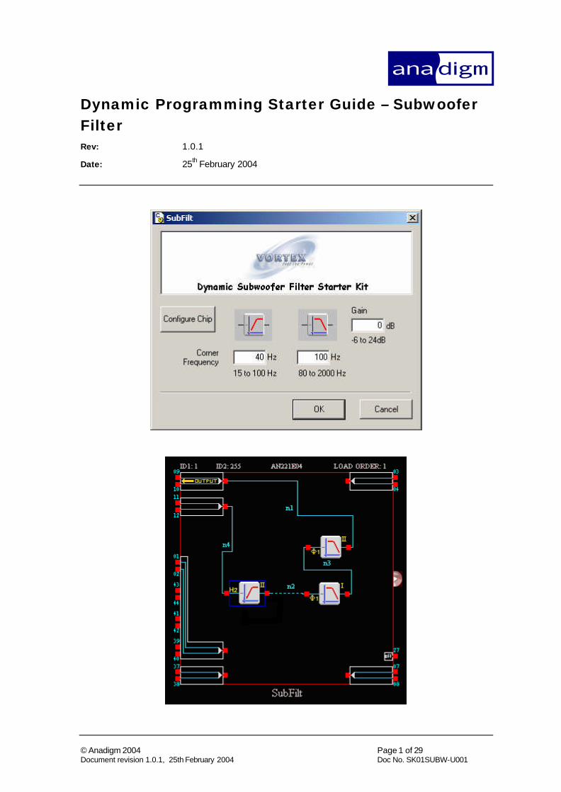
Dynamic Programming Starter Guide – Subwoofer Filter
© Anadigm 2004 Page 2 of 29 Document revision 1.0.1, 25th February 2004 Doc No. SK01SUBW-U001
TABLE OF CONTENTS 1 PURPOSE ................................................................................................................... 3
2 SETUP ......................................................................................................................... 4
2.1 BOARDS AND INTERFACE ....................................................................................... 4 2.1.1 Inputs and outputs....................................................................................... 4
2.2 SOFTWARE INSTALLATION..................................................................................... 6
3 CIRCUIT DESCRIPTION ........................................................................................ 7
3.1.1 4th Order Low-pass ...................................................................................... 8 3.1.2 High-pass Filter “Standard” ...................................................................... 9 3.1.3 High-pass Filter “Custom”....................................................................... 11
4 INSTANT PROTOTYPING USING ANADIGM'S DEVELOPMENT KIT..... 14
5 BUILDING DYNAMIC SOFTWARE CONTROL.............................................. 15
5.1 EXPORTING C-CODE APIS ................................................................................... 15 5.2 THE VIEW WITHIN A CASE TOOL ....................................................................... 16 5.3 BUILDING THE APPLICATION: “SUBFILT.EXE”..................................................... 18
5.3.1 Attaching dynamic programming to GUI controls: OnConfigure().......... 19 5.3.2 Other algorithmic controls: gain and frequency ....................................... 20
5.4 ALTERNATIVE DYNAMIC CONTROL – STATE-DRIVEN DYNAMIC UPDATE............ 21
6 PERFORMANCE..................................................................................................... 23
6.1 MEASUREMENT SETUP ........................................................................................ 23 6.2 SUMMARY OF MEASUREMENT RESULTS.............................................................. 26
7 CIRCUIT DEVELOPMENT .................................................................................. 29
Dynamic Programming Starter Guide – Subwoofer Filter
© Anadigm 2004 Page 3 of 29 Document revision 1.0.1, 25th February 2004 Doc No. SK01SUBW-U001
1 Purpose The purpose of this document is to introduce a method of prototyping dynamic programming of a simple ''subwoofer'' circuit which is realized in an Anadigm FPAA (Field Programmable Analog Array).
The circuit used is composed of CAMs (Configurable Analog Modules - Pre-built Analog Functional Blocks); the primary parameters of CAMs are both programmable (at design time) and dynamically re-programmable while the circuit is in use.
Anadigm's Software AnadigmDesigner®2 is used to create a CAM block level circuit schematic diagram; subsequently the same software is used to set the specific circuit attributes (parameters) desired.
In addition to an explanation of the circuit elements and circuit architecture, A step by step guide to reproducing the subwoofer circuit is provided this includes:-
• Building the circuit and setting the desired parameters using AnadigmDesigner®2 software,
• Instantly prototyping it using Anadigm's Development Kit (Part No. AN221E04-EVAL2).
• Measurements of the basic circuit performance.
• Controlling parameters and adding software control.
• Using the embedded, compiled, c-code application.
Dynamic Programming Starter Guide – Subwoofer Filter
© Anadigm 2004 Page 4 of 29 Document revision 1.0.1, 25th February 2004 Doc No. SK01SUBW-U001
2 Setup
2.1 Boards and interface
2.1.1 Inputs and outputs
The AN221K04 development board should be connected to the PC via the serial interface & cable provided. Depending on the type of signalling involved, the user may wish to make some custom modifications to the board. This section recommends various options.
It is recommended that all signalling into and out of the evaluation board be done differentially.
The reader is referred to the AN221K04 Evaluation Board User Manual, (Anadigm Document Number UM30900-U010) for full details.
The above user manual recommends various input and output interface circuits for ease of connection to audio sources and active speakers.
C For formal performance tests all measurement instrumentation should connect directly to the FPAA header pins without any additional circuitry in the signal path.
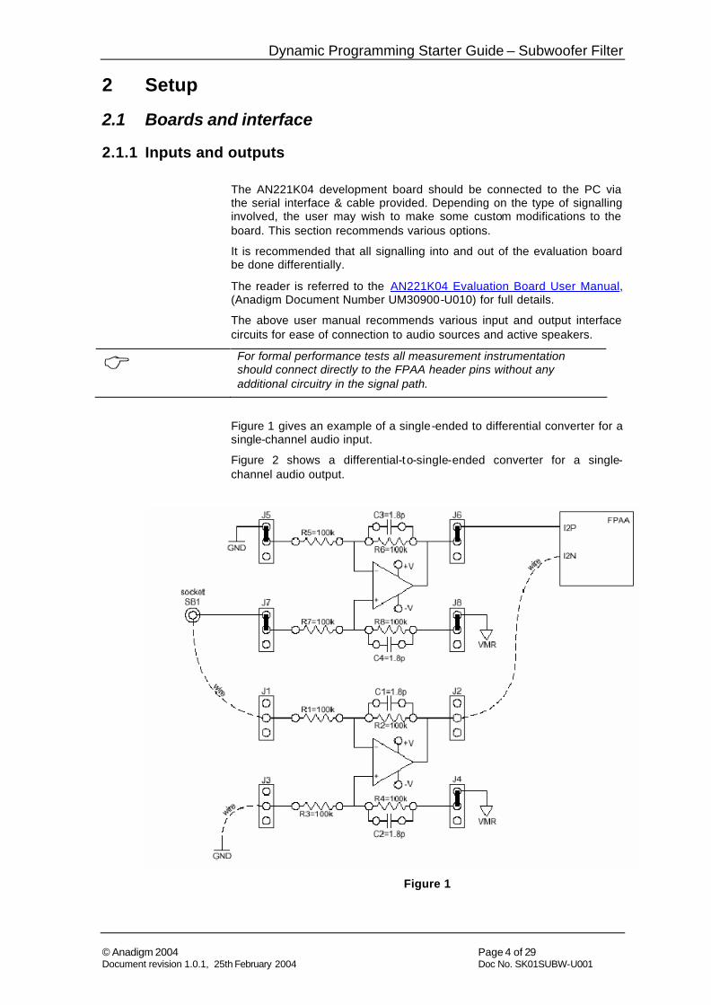
Figure 1 gives an example of a single-ended to differential converter for a single-channel audio input.
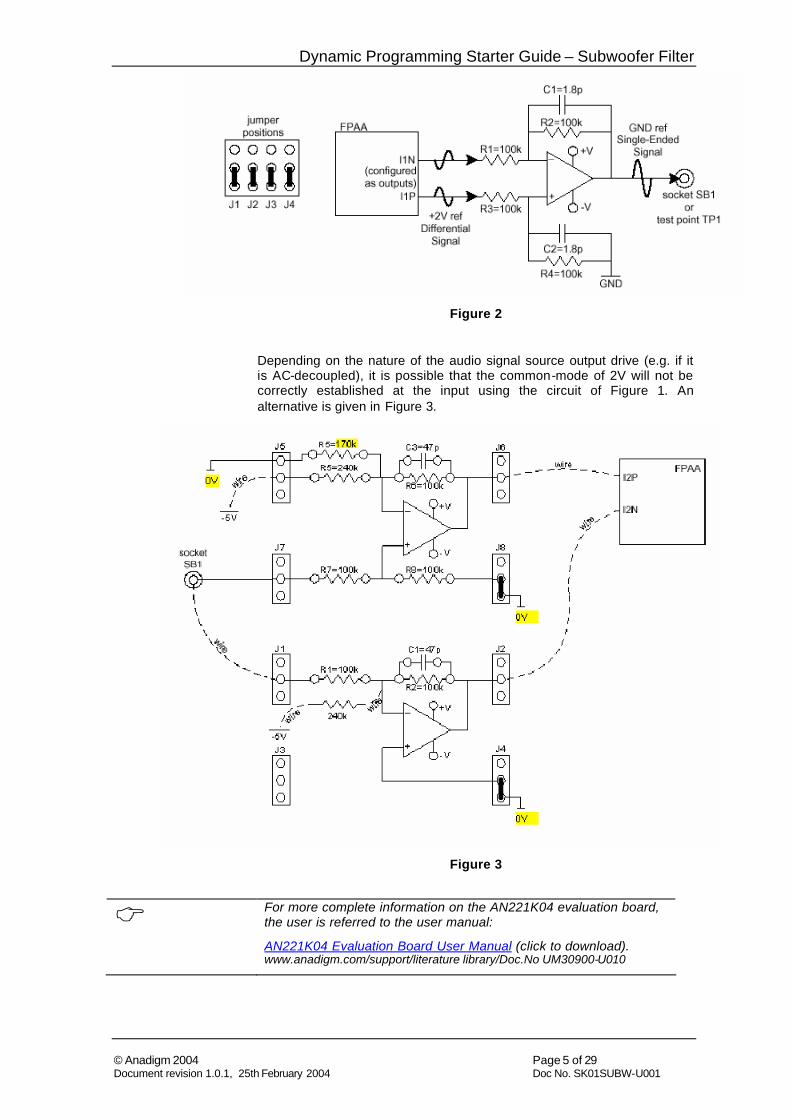
Figure 2 shows a differential-to-single-ended converter for a single-channel audio output.
Figure 1
Dynamic Programming Starter Guide – Subwoofer Filter
© Anadigm 2004 Page 5 of 29 Document revision 1.0.1, 25th February 2004 Doc No. SK01SUBW-U001
Figure 2
Depending on the nature of the audio signal source output drive (e.g. if it is AC-decoupled), it is possible that the common-mode of 2V will not be correctly established at the input using the circuit of Figure 1. An alternative is given in Figure 3.
Figure 3
C For more complete information on the AN221K04 evaluation board, the user is referred to the user manual:
AN221K04 Evaluation Board User Manual (click to download). www.anadigm.com/support/literature library/Doc.No UM30900-U010
Dynamic Programming Starter Guide – Subwoofer Filter
© Anadigm 2004 Page 6 of 29 Document revision 1.0.1, 25th February 2004 Doc No. SK01SUBW-U001
2.2 Software installation No installation is necessary; having copied the contents of the starter kit to your PC, go to the directory
“…\SubFilt application\SubFilt executable\”
and double click on SubFilt.exe.
This software will only operate with an AN221K04 evaluation kit, connected to the PC’s serial port using standard serial connector.
C Disclaimer:
Anadigm does not make any warranty or representation as to the functionality or otherwise of the SubFilt application tool and all warranties implied or express are excluded to the extent permitted by applicable law. Anadigm does not provide product support for this software.
Dynamic Programming Starter Guide – Subwoofer Filter
© Anadigm 2004 Page 7 of 29 Document revision 1.0.1, 25th February 2004 Doc No. SK01SUBW-U001
3 Circuit description
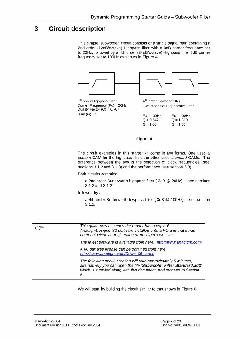
This simple 'subwoofer' circuit consists of a single signal path containing a 2nd order (12dB/octave) Highpass filter with a 3dB corner frequency set to 20Hz, followed by a 4th order (24dB/octave) Highpass filter 3dB corner frequency set to 100Hz as shown in Figure 4
Figure 4
The circuit examples in this starter kit come in two forms. One uses a custom CAM for the highpass filter, the other uses standard CAMs. The difference between the two is the selection of clock frequencies (see sections 3.1.2 and 3.1.3) and the performance (see section 5.3).
Both circuits comprise:
- a 2nd order Butterworth highpass filter (-3dB @ 20Hz) - see sections 3.1.2 and 3.1.3
followed by a
- a 4th order Butterworth lowpass filter (-3dB @ 100Hz) – see section 3.1.1.
C This guide now assumes the reader has a copy of AnadigmDesigner®2 software installed onto a PC and that it has been unlocked via registration at Anadigm’s website.
The latest software is available from here. http://www.anadigm.com/
A 60 day free license can be obtained from here http://www.anadigm.com/Down_05_a.asp
The following circuit creation will take approximately 5 minutes; alternatively you can open the file “Subwoofer Filter Standard.ad2” which is supplied along with this document, and proceed to Section 5.
We will start by building the circuit similar to that shown in Figure 6.
2nd order Highpass Filter Corner Frequency (Fc) = 20Hz Quality Factor (Q) = 0.707 Gain (G) = 1
4th Order Lowpass filter Two stages of Biquadratic Filter
Fc = 100Hz Q = 0.542 G = 1.00
Fc = 100Hz Q = 1.310 G = 1.00
Dynamic Programming Starter Guide – Subwoofer Filter
© Anadigm 2004 Page 8 of 29 Document revision 1.0.1, 25th February 2004 Doc No. SK01SUBW-U001
3.1.1 4th Order Low-pass
This circuit is common to both designs and is the second stage of the design.
The filter was generated using AnadigmFilter, in which a second order lowpass Butterworth filter was selected, with corner frequency of 0.1kHz. It is noted that the filter coefficients for each stage are:
Instance Clock Module Type Phase Fo-Khz DC Gn HF Gn Q
CAM: Stage0 ClockA 0 FILTERBIQUAD LP 1 0.1 1 0.541
CAM: Stage1 ClockA 0 FILTERBIQUAD LP 1 0.1 1 1.31
These parameters, when passed to the FilterBiquad CAM, realize the 100Hz lowpass Butterworth characteristic.
The objective is to make corner frequencies of both filters programmable under software control. This is possible using algorithmic dynamic reconfiguration feature supported in AnadigmDesigner®2. To do this one generates C-code for each of the CAMs (FilterBiquads in this case) in the circuit. This code calculates new filter programming based on the biquad parameters listed above.
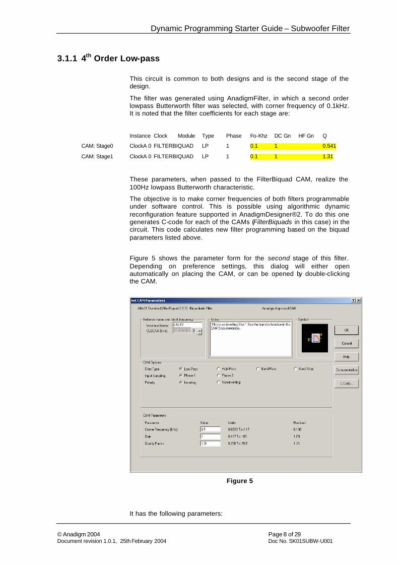
Figure 5 shows the parameter form for the second stage of this filter. Depending on preference settings, this dialog will either open automatically on placing the CAM, or can be opened by double-clicking the CAM.
Figure 5
It has the following parameters:
Dynamic Programming Starter Guide – Subwoofer Filter
© Anadigm 2004 Page 9 of 29 Document revision 1.0.1, 25th February 2004 Doc No. SK01SUBW-U001
- it is driven by Clock 3 which is assigned a frequency of 41.667kHz (see next sections for the assignment of clock frequency)
- the instance has been assigned the name “LRLP2”
- the corner frequency has been set to 100Hz
- the gain is set to 1
- the Q factor (2nd biquad stage) is set to 1.31
When dynamically programming these parameters, to maintain the Butterworth characteristic of the 4th order filter, the separate 2nd order biquad stages must be reconfigured with a new set of parameter values which:
- varies the value - but maintains the ratio - between the respective biquad corner frequencies, Fo, (in this case the ratio is 1)
- maintains the respective values of the biquad ‘Q’ factors. (in this case 0.541 and 1.31).
- sets the gain of the overall circuit by varying the gain of the first CAM in the chain
Section 5 discusses the software construction in more detail.
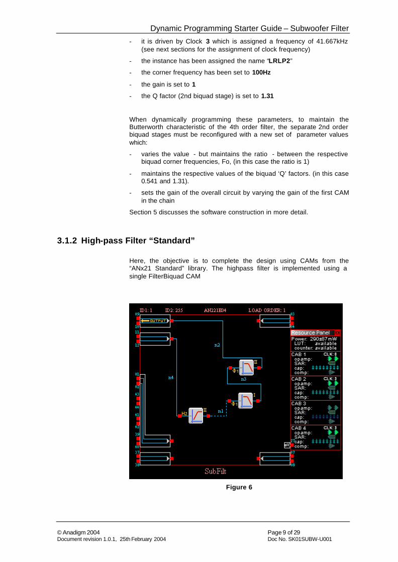
3.1.2 High-pass Filter “Standard”
Here, the objective is to complete the design using CAMs from the “ANx21 Standard” library. The highpass filter is implemented using a single FilterBiquad CAM
Figure 6
Dynamic Programming Starter Guide – Subwoofer Filter
© Anadigm 2004 Page 10 of 29 Document revision 1.0.1, 25th February 2004 Doc No. SK01SUBW-U001
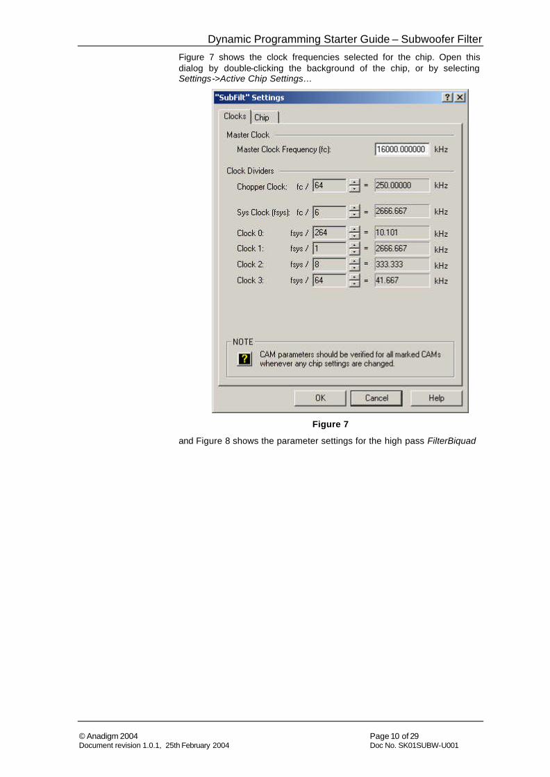
Figure 7 shows the clock frequencies selected for the chip. Open this dialog by double-clicking the background of the chip, or by selecting Settings->Active Chip Settings…
Figure 7
and Figure 8 shows the parameter settings for the high pass FilterBiquad
Dynamic Programming Starter Guide – Subwoofer Filter
© Anadigm 2004 Page 11 of 29 Document revision 1.0.1, 25th February 2004 Doc No. SK01SUBW-U001
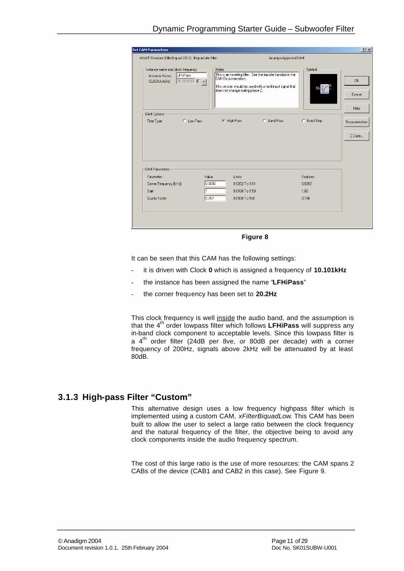
Figure 8
It can be seen that this CAM has the following settings:
- it is driven with Clock 0 which is assigned a frequency of 10.101kHz
- the instance has been assigned the name “LFHiPass”
- the corner frequency has been set to 20.2Hz
This clock frequency is well inside the audio band, and the assumption is that the 4th order lowpass filter which follows LFHiPass will suppress any in-band clock component to acceptable levels. Since this lowpass filter is a 4th order filter (24dB per 8ve, or 80dB per decade) with a corner frequency of 200Hz, signals above 2kHz will be attenuated by at least 80dB.
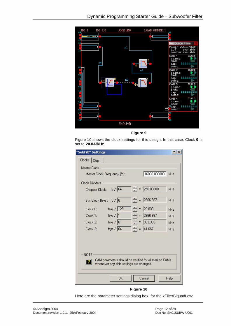
3.1.3 High-pass Filter “Custom” This alternative design uses a low frequency highpass filter which is implemented using a custom CAM, xFilterBiquadLow. This CAM has been built to allow the user to select a large ratio between the clock frequency and the natural frequency of the filter, the objective being to avoid any clock components inside the audio frequency spectrum.
The cost of this large ratio is the use of more resources: the CAM spans 2 CABs of the device (CAB1 and CAB2 in this case). See Figure 9.
Dynamic Programming Starter Guide – Subwoofer Filter
© Anadigm 2004 Page 12 of 29 Document revision 1.0.1, 25th February 2004 Doc No. SK01SUBW-U001
Figure 9
Figure 10 shows the clock settings for this design. In this case, Clock 0 is set to 20.833kHz.
Figure 10
Here are the parameter settings dialog box for the xFilterBiquadLow:
Dynamic Programming Starter Guide – Subwoofer Filter
© Anadigm 2004 Page 13 of 29 Document revision 1.0.1, 25th February 2004 Doc No. SK01SUBW-U001
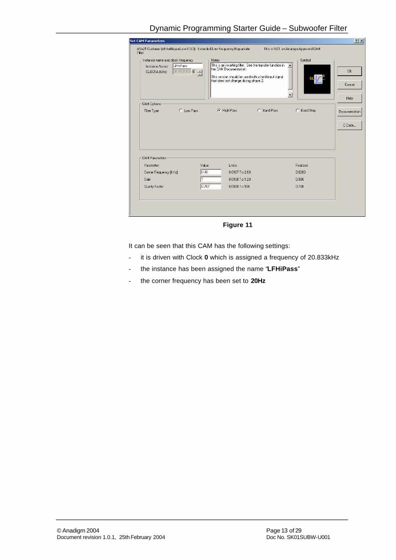
Figure 11
It can be seen that this CAM has the following settings:
- it is driven with Clock 0 which is assigned a frequency of 20.833kHz
- the instance has been assigned the name “LFHiPass”
- the corner frequency has been set to 20Hz
Dynamic Programming Starter Guide – Subwoofer Filter
© Anadigm 2004 Page 14 of 29 Document revision 1.0.1, 25th February 2004 Doc No. SK01SUBW-U001
4 Instant prototyping using Anadigm's Development Kit
C This guide now additionally assumes the reader has purchased an Anadigm development kit (Part No. AN221K04), has unpacked it, read the Quickstart Guide and has connected the board to a suitable power source and the PC serial port. Detailed information for purchasing a kit can be found here: http://www.anadigm.com/Prod_10_c.asp
Having connected a development board to a PC which has a copy of AnadigmDesigner®2 running to configure the FPAA on the development board you simply, open your circuit then from the software select Configure->Write configuration data to serial port . The circuit is now ready for testing.
The following should be considered before connecting a signal or measurement unit.
i) Common-mode signalling on the development board is set to Vss + 2 volts. This may influence the circuit used to interface both siqnal into and out of the FPAA.
ii) The FPAA has a fully differential architecture, use this whenever possible. The FPAA has single to differential conversion capability at its input and vice-versa the output cells. Examples of external Op Amp circuits to provide level shifting and other common functions con be found in Anadiqm’s Development Board User Guide.
iii) A good quality power supply should be used to power the development board, again refer to the Development Board User Guide for details.
iv) For convenience you may want to add audio connectors, configure the development board op-amps to perform input and output signal conditioning functions so that the board can readily be connected to your existing product or test environment. Examples of this are shown in Section 2.1.1.
v) Popular audio test equipment can source and measure differential signals that are have the 2V offset necessary to connect a signal directly to the FPAA. The test results shown below have been measured by directly sourcing and measuring signals at the header pins provided beside the FPAA on the development board.
Dynamic Programming Starter Guide – Subwoofer Filter
© Anadigm 2004 Page 15 of 29 Document revision 1.0.1, 25th February 2004 Doc No. SK01SUBW-U001
5 Building Dynamic Software Control
In our project we want the microprocessor (a PC in this case) to calculate new circuit settings on the fly, so we will choose Algorithmic dynamic configuration:
(For a note on State-Driven dynamic configuration see Section 5.4)
5.1 Exporting C-code APIs Once the basic design is complete, AnadigmDesigner®2 can generate purpose-built C-code functions which allow manipulation of that design under software control without the user needing to know low-level configuration detail.
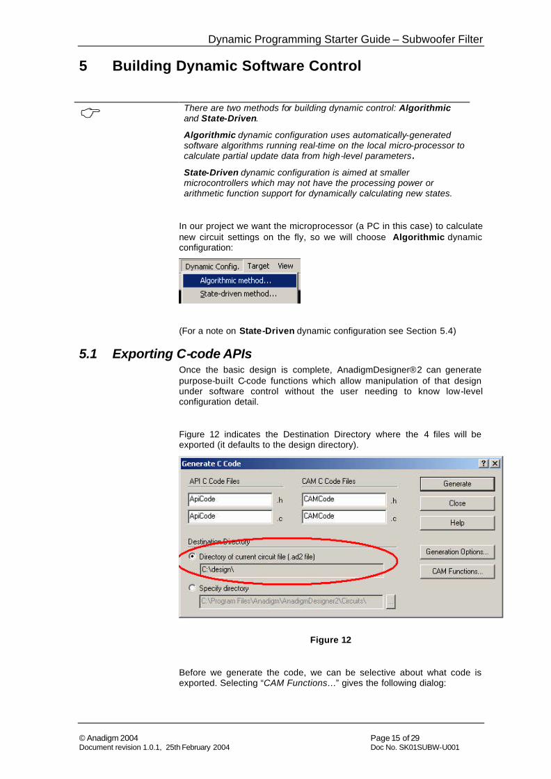
Figure 12 indicates the Destination Directory where the 4 files will be exported (it defaults to the design directory).
Figure 12
Before we generate the code, we can be selective about what code is exported. Selecting “CAM Functions…” gives the following dialog:
C There are two methods for building dynamic control: Algorithmic and State-Driven.
Algorithmic dynamic configuration uses automatically-generated software algorithms running real-time on the local micro-processor to calculate partial update data from high-level parameters .
State-Driven dynamic configuration is aimed at smaller microcontrollers which may not have the processing power or arithmetic function support for dynamically calculating new states.
Dynamic Programming Starter Guide – Subwoofer Filter
© Anadigm 2004 Page 16 of 29 Document revision 1.0.1, 25th February 2004 Doc No. SK01SUBW-U001
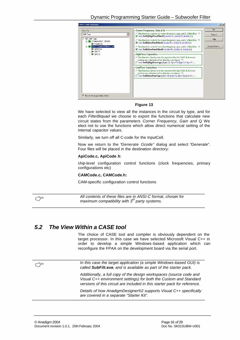
Figure 13
We have selected to view all the instances in the circuit by type, and for each FilterBiquad we choose to export the functions that calculate new circuit states from the parameters Corner Frequency, Gain and Q. We elect not to use the functions which allow direct numerical setting of the internal capacitor values.
Similarly, we turn off all C-code for the InputCell.
Now we return to the “Generate C-code” dialog and select “Generate”. Four files will be placed in the destination directory:
ApiCode.c, ApiCode .h:
chip-level configuration control functions (clock frequencies, primary configurations etc)
CAMCode.c, CAMCode.h:
CAM-specific configuration control functions
C All contents of these files are in ANSI-C format, chosen for maximum compatibility with 3rd party systems.
5.2 The View Within a CASE tool The choice of CASE tool and compiler is obviously dependent on the target processor. In this case we have selected Microsoft Visual C++ in order to develop a simple Windows-based application which can reconfigure the FPAA on the development board via the serial port.
C In this case the target application (a simple Windows-based GUI) is called SubFilt.exe, and is available as part of the starter pack.
Additionally, a full copy of the design workspaces (source code and Visual C++ environment settings) for both the Custom and Standard versions of this circuit are included in this starter pack for reference.
Details of how AnadigmDesigner®2 supports Visual C++ specifically are covered in a separate “Starter Kit”.
Dynamic Programming Starter Guide – Subwoofer Filter
© Anadigm 2004 Page 17 of 29 Document revision 1.0.1, 25th February 2004 Doc No. SK01SUBW-U001
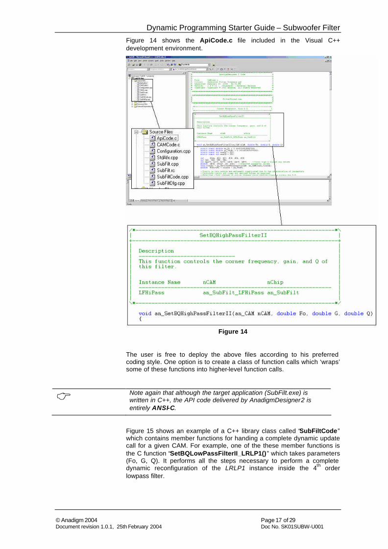
Figure 14 shows the ApiCode.c file included in the Visual C++ development environment.
Figure 14
The user is free to deploy the above files according to his preferred coding style. One option is to create a class of function calls which ‘wraps’ some of these functions into higher-level function calls.
C Note again that although the target application (SubFilt.exe) is written in C++, the API code delivered by AnadigmDesigner2 is entirely ANSI-C.
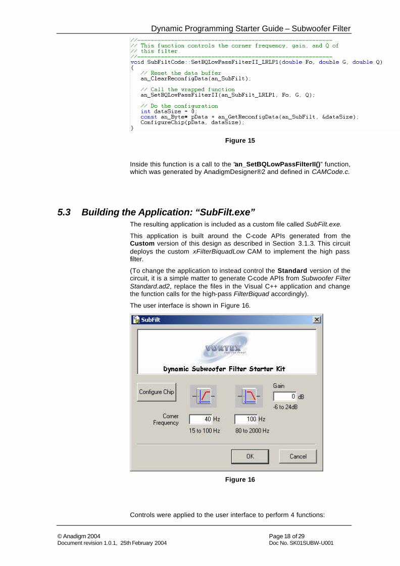
Figure 15 shows an example of a C++ library class called “SubFiltCode” which contains member functions for handing a complete dynamic update call for a given CAM. For example, one of the these member functions is the C function “SetBQLowPassFilterII_LRLP1()” which takes parameters (Fo, G, Q). It performs all the steps necessary to perform a complete dynamic reconfiguration of the LRLP1 instance inside the 4th order lowpass filter.
Dynamic Programming Starter Guide – Subwoofer Filter
© Anadigm 2004 Page 18 of 29 Document revision 1.0.1, 25th February 2004 Doc No. SK01SUBW-U001
Figure 15
Inside this function is a call to the “an_SetBQLowPassFilterII()” function, which was generated by AnadigmDesigner®2 and defined in CAMCode.c.
5.3 Building the Application: “SubFilt.exe” The resulting application is included as a custom file called SubFilt.exe.
This application is built around the C-code APIs generated from the Custom version of this design as described in Section 3.1.3. This circuit deploys the custom xFilterBiquadLow CAM to implement the high pass filter.
(To change the application to instead control the Standard version of the circuit, it is a simple matter to generate C-code APIs from Subwoofer Filter Standard.ad2, replace the files in the Visual C++ application and change the function calls for the high-pass FilterBiquad accordingly).
The user interface is shown in Figure 16.
Figure 16
Controls were applied to the user interface to perform 4 functions:
Dynamic Programming Starter Guide – Subwoofer Filter
© Anadigm 2004 Page 19 of 29 Document revision 1.0.1, 25th February 2004 Doc No. SK01SUBW-U001
• Configure the device
• Change high-pass filter cut-off frequency
• Change low-pass filter cut-off frequency
• Change signal path gain
Using the Resource Editor in Visual C++, a dialog box is designed which includes controls for performing each of these functions.
5.3.1 Attaching dynamic programming to GUI controls: OnConfigure()
Before any dynamic control is performed, the FPAA must be loaded with the correct circuit configuration. This can be done automatically when the application is invoked, or (as in this case) the facility can be added under push-button control.
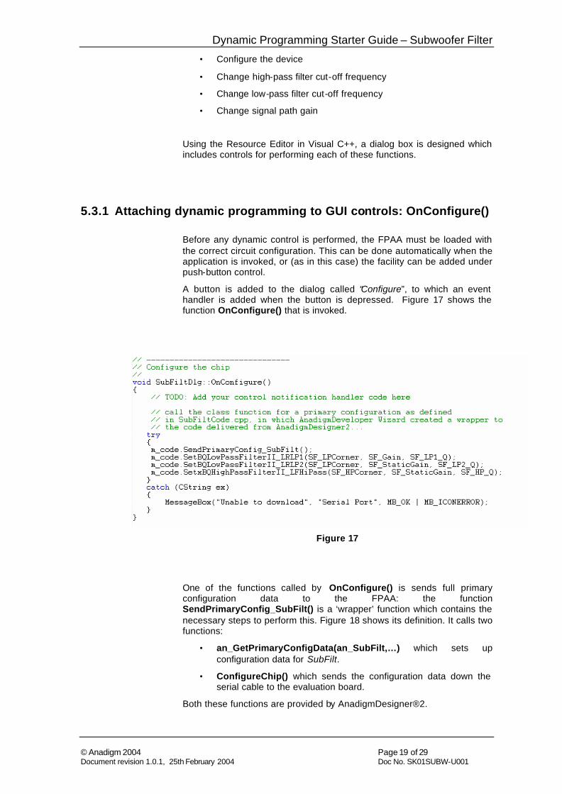
A button is added to the dialog called “Configure”, to which an event handler is added when the button is depressed. Figure 17 shows the function OnConfigure() that is invoked.
Figure 17
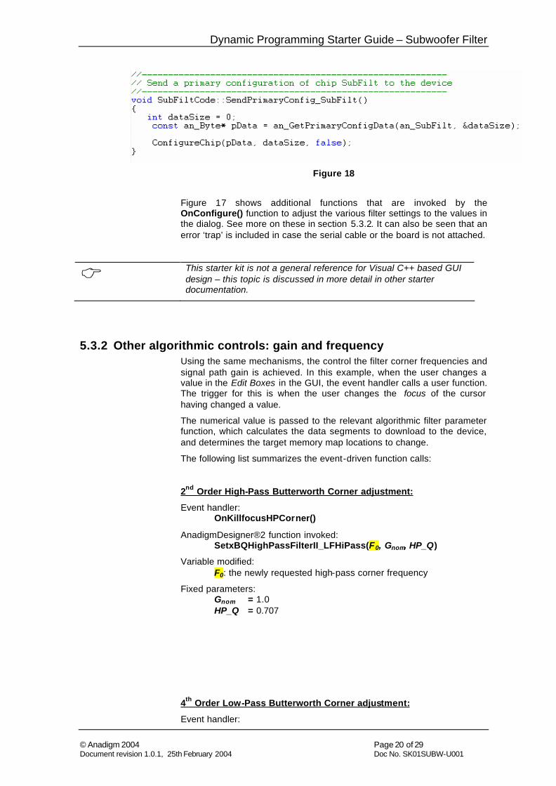
One of the functions called by OnConfigure() is sends full primary configuration data to the FPAA: the function SendPrimaryConfig_SubFilt() is a ‘wrapper’ function which contains the necessary steps to perform this. Figure 18 shows its definition. It calls two functions:
• an_GetPrimaryConfigData(an_SubFilt,…) which sets up configuration data for SubFilt.
• ConfigureChip() which sends the configuration data down the serial cable to the evaluation board.
Both these functions are provided by AnadigmDesigner®2.
Dynamic Programming Starter Guide – Subwoofer Filter
© Anadigm 2004 Page 20 of 29 Document revision 1.0.1, 25th February 2004 Doc No. SK01SUBW-U001
Figure 18
Figure 17 shows additional functions that are invoked by the OnConfigure() function to adjust the various filter settings to the values in the dialog. See more on these in section 5.3.2. It can also be seen that an error ‘trap’ is included in case the serial cable or the board is not attached.
C This starter kit is not a general reference for Visual C++ based GUI design – this topic is discussed in more detail in other starter documentation.
5.3.2 Other algorithmic controls: gain and frequency Using the same mechanisms, the control the filter corner frequencies and signal path gain is achieved. In this example, when the user changes a value in the Edit Boxes in the GUI, the event handler calls a user function. The trigger for this is when the user changes the focus of the cursor having changed a value.
The numerical value is passed to the relevant algorithmic filter parameter function, which calculates the data segments to download to the device, and determines the target memory map locations to change.
The following list summarizes the event-driven function calls:
2nd Order High-Pass Butterworth Corner adjustment:
Event handler: OnKillfocusHPCorner()
AnadigmDesigner®2 function invoked: SetxBQHighPassFilterII_LFHiPass(F0, Gnom, HP_Q)
Variable modified: F0: the newly requested high-pass corner frequency
Fixed parameters: Gnom = 1.0 HP_Q = 0.707
4th Order Low-Pass Butterworth Corner adjustment:
Event handler:
Dynamic Programming Starter Guide – Subwoofer Filter
© Anadigm 2004 Page 21 of 29 Document revision 1.0.1, 25th February 2004 Doc No. SK01SUBW-U001
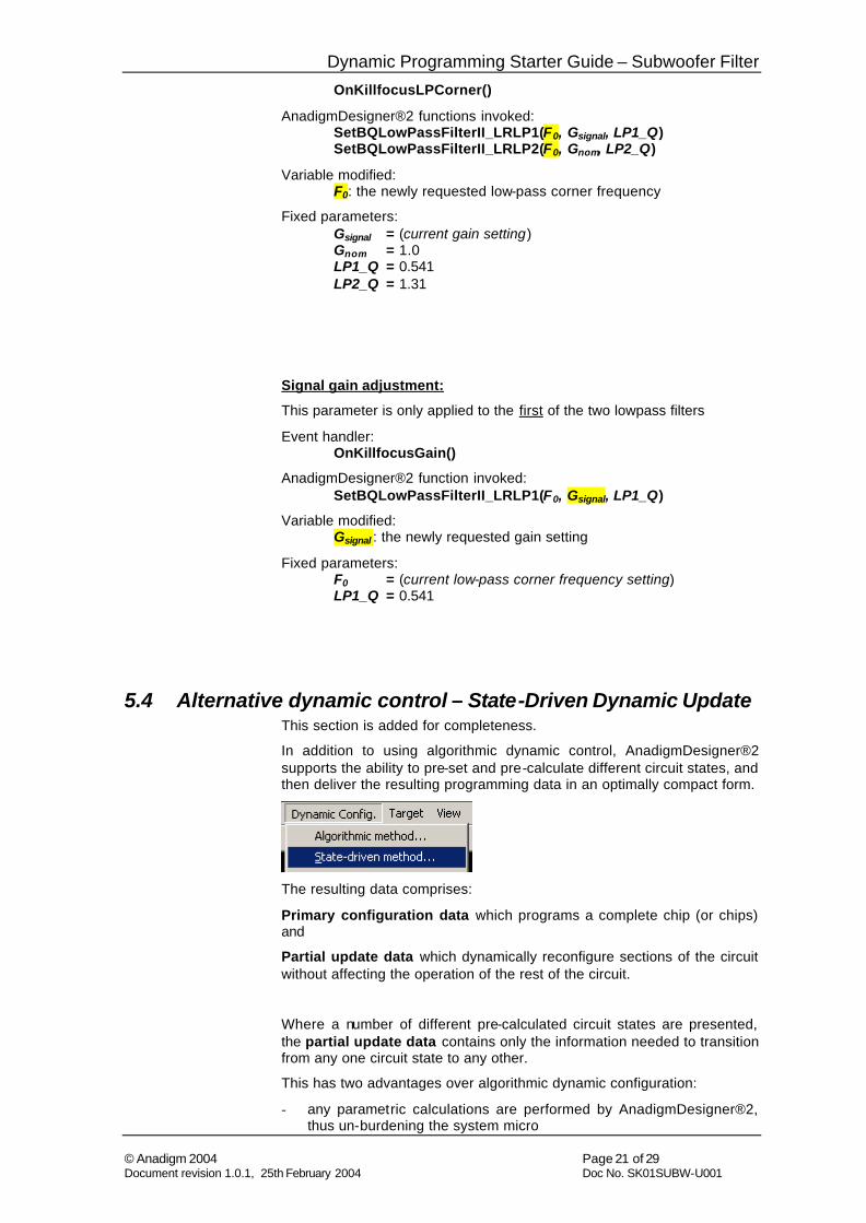
OnKillfocusLPCorner()
AnadigmDesigner®2 functions invoked: SetBQLowPassFilterII_LRLP1(F0, Gsignal, LP1_Q) SetBQLowPassFilterII_LRLP2(F0, Gnom, LP2_Q)
Variable modified: F0: the newly requested low-pass corner frequency
Fixed parameters: Gsignal = (current gain setting) Gnom = 1.0 LP1_Q = 0.541 LP2_Q = 1.31
Signal gain adjustment:
This parameter is only applied to the first of the two lowpass filters
Event handler: OnKillfocusGain()
AnadigmDesigner®2 function invoked: SetBQLowPassFilterII_LRLP1(F0, Gsignal, LP1_Q)
Variable modified: Gsignal : the newly requested gain setting
Fixed parameters: F0 = (current low-pass corner frequency setting) LP1_Q = 0.541
5.4 Alternative dynamic control – State-Driven Dynamic Update This section is added for completeness.
In addition to using algorithmic dynamic control, AnadigmDesigner®2 supports the ability to pre-set and pre-calculate different circuit states, and then deliver the resulting programming data in an optimally compact form.
The resulting data comprises:
Primary configuration data which programs a complete chip (or chips) and
Partial update data which dynamically reconfigure sections of the circuit without affecting the operation of the rest of the circuit.
Where a number of different pre-calculated circuit states are presented, the partial update data contains only the information needed to transition from any one circuit state to any other.
This has two advantages over algorithmic dynamic configuration:
- any parametric calculations are performed by AnadigmDesigner®2, thus un-burdening the system micro
Dynamic Programming Starter Guide – Subwoofer Filter
© Anadigm 2004 Page 22 of 29 Document revision 1.0.1, 25th February 2004 Doc No. SK01SUBW-U001
- the transition data is presented in an optimally compact form, saving system memory.
The disadvantage is the need for the designer to anticipate any circuit settings that may be required at run-time.
The datasets arising from state-driven dynamic update can be delivered in two forms:
C-code APIs: as with the algorithmic API code, the state-driven code can have a C-code ‘wrapper’ for easy inclusion in C-based microcode.
Raw data: this can be written to file for burn to PROM, or for incorporation in, e.g., assembler code.
C The reader is referred to the AnadigmDesigner®2 User Guide and help information for more detail on the use of this feature.
Dynamic Programming Starter Guide – Subwoofer Filter
© Anadigm 2004 Page 23 of 29 Document revision 1.0.1, 25th February 2004 Doc No. SK01SUBW-U001
6 Performance
Measurements were taken using Audio Precision test equipment, capable of sourcing and measuring differential signals with a 2V DC common mode offset, therefore no input or output signal conditioning has been used around the FPAA, both source and measurement are taken directly at the FPAA I/O pins.
The circuit under test was Subwoofer Filter Custom.ad2.
All measurements were taken at the settings assigned in the .ad2 file.
6.1 Measurement Setup
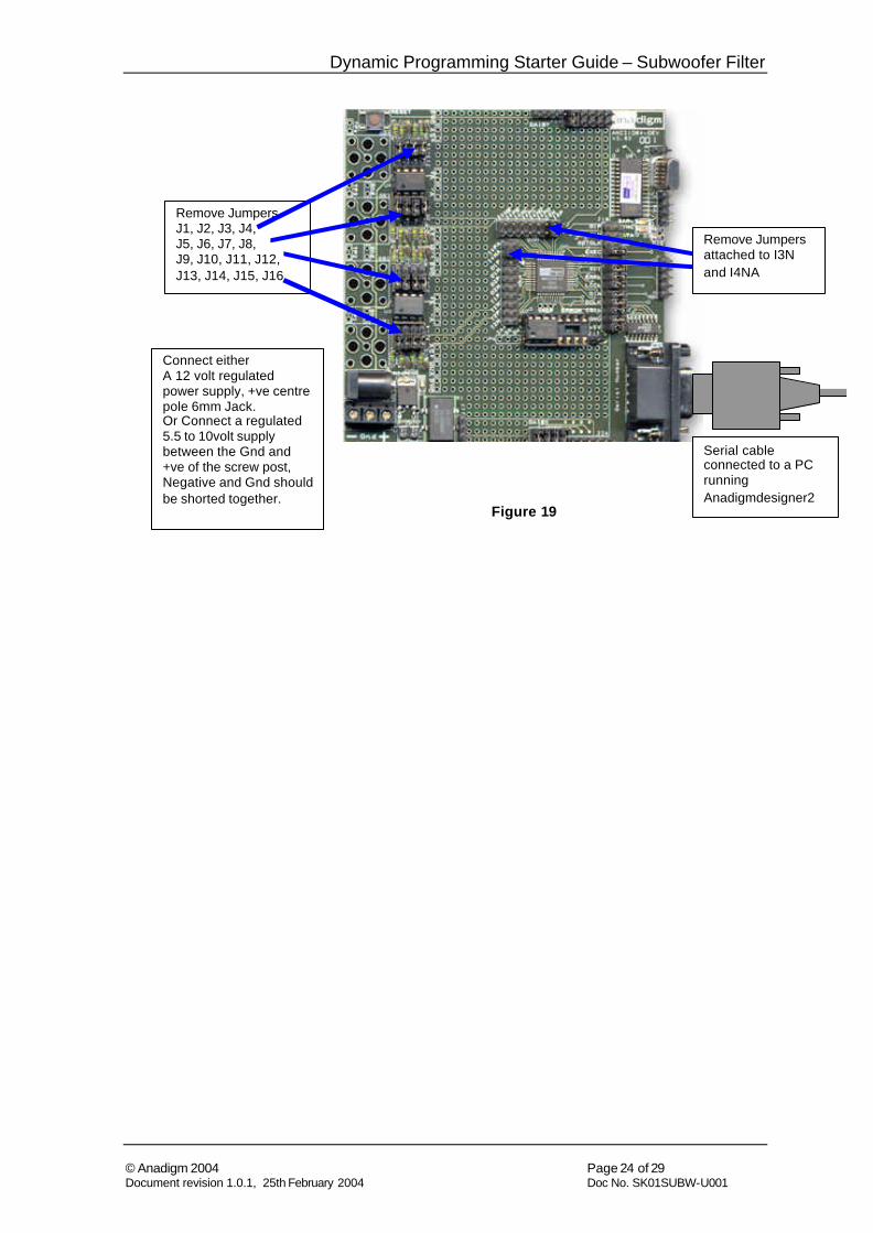
To reproduce these results, the following AN221K04 Development Kit board setting should be arranged. The following assumes the board is in its default state, as shipped from Anadigm.
i) Connect the serial cable to Development board, the other end connect to a PC running Anadigmdesigner2. Test circuits will be loaded through this connection from the software.
ii) Connect a quiet power source to the board, Anadigm recommends a regulated 5.5 to 10volt supply between the Gnd and +ve of the screw post at the same time the -ve and Gnd posts should be shorted together. Alternatively 12 volt regulated power supply, +ve centre pole 6mm Jack can be used , Do not use both simultaneously.
iii) Remove Jumpers all the jumpers numbered J1 to J16, this completely isolates the input and output pins of the FPAA device from the input/output conditioning analog board circuitry.
iv) Remove Jumpers attached to The FPAA header pins I3N and I4NA, these connections from inputs to VMR are only used for single ended input signals.
See Figure 19,
C If the PC and board power supply grounds potentials differ this may cause noise, to guarantee that digital circuit noise does not influence the Audio results the serial cable should be removed before measurement. This is recommended
Removing all the jumpers from J18 on the development board will fully isolate and power down the digital section of the board, Anadigm has not observed any influence from the digital circuitry on the board once the circuit is programmed, this does not seem necessary
Obviously to reprogram the FPAA these connection need replacing.
Dynamic Programming Starter Guide – Subwoofer Filter
© Anadigm 2004 Page 24 of 29 Document revision 1.0.1, 25th February 2004 Doc No. SK01SUBW-U001
Figure 19
Serial cable connected to a PC running Anadigmdesigner2
Connect either A 12 volt regulated power supply, +ve centre pole 6mm Jack. Or Connect a regulated 5.5 to 10volt supply between the Gnd and +ve of the screw post, Negative and Gnd should be shorted together.
Remove Jumpers J1, J2, J3, J4, J5, J6, J7, J8, J9, J10, J11, J12, J13, J14, J15, J16
Remove Jumpers attached to I3N and I4NA
Dynamic Programming Starter Guide – Subwoofer Filter
© Anadigm 2004 Page 25 of 29 Document revision 1.0.1, 25th February 2004 Doc No. SK01SUBW-U001
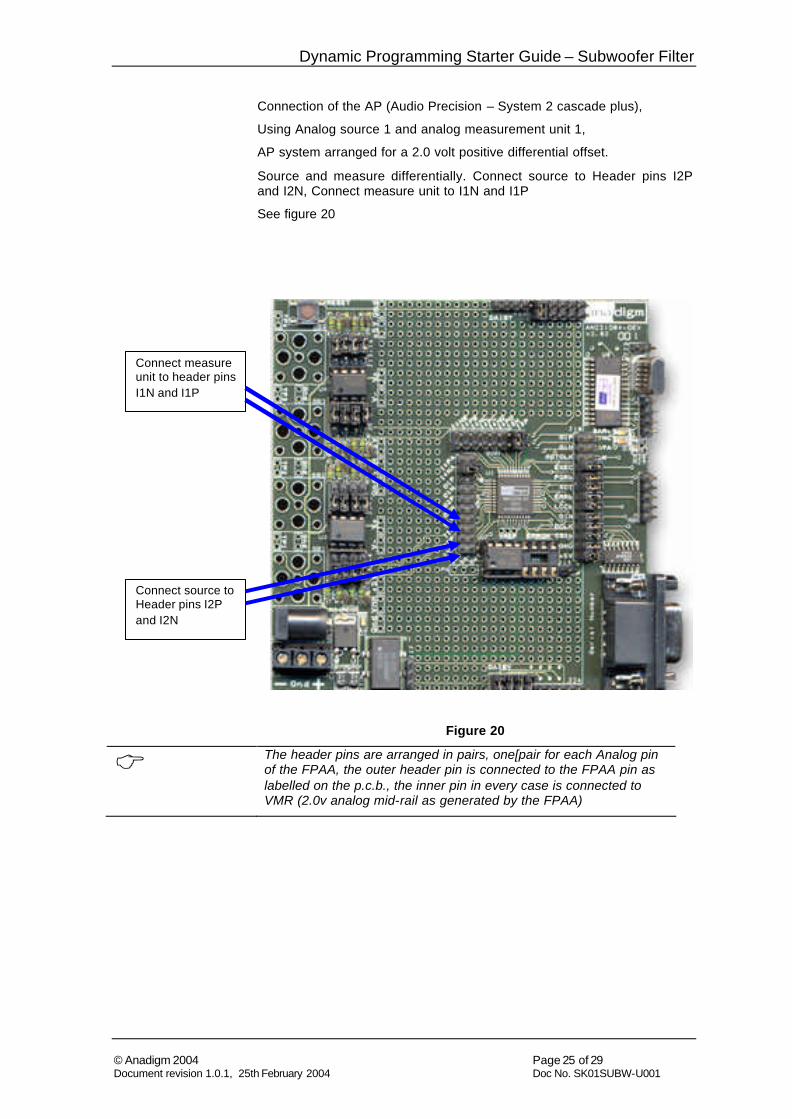
Connection of the AP (Audio Precision – System 2 cascade plus),
Using Analog source 1 and analog measurement unit 1,
AP system arranged for a 2.0 volt positive differential offset.
Source and measure differentially. Connect source to Header pins I2P and I2N, Connect measure unit to I1N and I1P
See figure 20
Figure 20
C The header pins are arranged in pairs, one[pair for each Analog pin of the FPAA, the outer header pin is connected to the FPAA pin as labelled on the p.c.b., the inner pin in every case is connected to VMR (2.0v analog mid-rail as generated by the FPAA)
Connect source to Header pins I2P and I2N
Connect measure unit to header pins I1N and I1P
Dynamic Programming Starter Guide – Subwoofer Filter
© Anadigm 2004 Page 26 of 29 Document revision 1.0.1, 25th February 2004 Doc No. SK01SUBW-U001
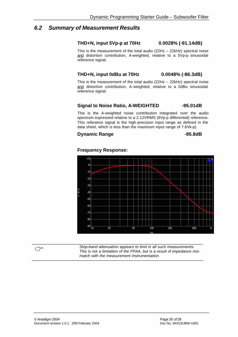
6.2 Summary of Measurement Results
THD+N, input 5Vp-p at 70Hz 0.0028% (-91.14dB)
This is the measurement of the total audio (22Hz – 22kHz) spectral noise and distortion contribution, A-weighted, relative to a 5Vp-p sinusoidal reference signal.
THD+N, input 0dBu at 70Hz 0.0048% (-86.3dB) This is the measurement of the total audio (22Hz – 22kHz) spectral noise and distortion contribution, A-weighted, relative to a 0dBu sinusoidal reference signal.
Signal to Noise Ratio, A-WEIGHTED -95.01dB This is the A-weighted noise contribution integrated over the audio spectrum expressed relative to a 2.12VRMS (6Vp-p differential) reference. This reference signal is the high-precision input range as defined in the data sheet, which is less than the maximum input range of 7.6Vk-p).
Dynamic Range -95.8dB
Frequency Response:
C Stop-band attenuation appears to limit in all such measurements. This is not a limitation of the FPAA, but is a result of impedance mis-match with the measurement instrumentation.
Dynamic Programming Starter Guide – Subwoofer Filter
© Anadigm 2004 Page 27 of 29 Document revision 1.0.1, 25th February 2004 Doc No. SK01SUBW-U001
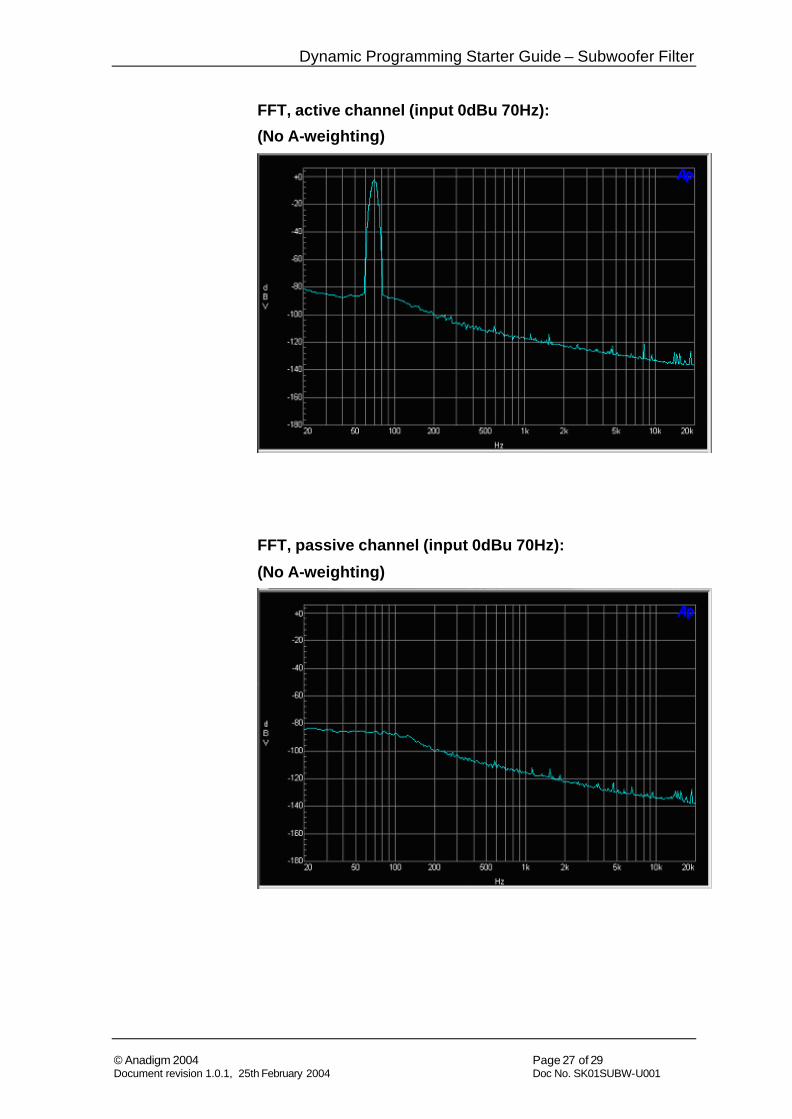
FFT, active channel (input 0dBu 70Hz):
(No A-weighting)
FFT, passive channel (input 0dBu 70Hz): (No A-weighting)
Dynamic Programming Starter Guide – Subwoofer Filter
© Anadigm 2004 Page 28 of 29 Document revision 1.0.1, 25th February 2004 Doc No. SK01SUBW-U001
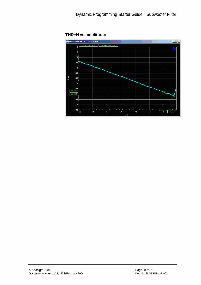
THD+N vs amplitude:
Dynamic Programming Starter Guide – Subwoofer Filter
© Anadigm 2004 Page 29 of 29 Document revision 1.0.1, 25th February 2004 Doc No. SK01SUBW-U001
7 Circuit Development Anadigm now invites the reader to continue to develop this circuit or an alternative circuit to meet specific needs. For example, a compressor: a circuit implementing non-linear closed loop gain or amplitude control. Examples of such circuits will be made available as further Starter Kits.
Additional filter circuits (e.g. Linkwitz Transform EQ) are under investigation internally and will be published in future editions of this starter guide.