dynamic thermostatic radiator valves dynamical234 series dynamic thermostatic radiator valve,...
TRANSCRIPT
Product range
VALVES:
For steel pipes:230 series Dynamic thermostatic radiator valve, angled version sizes 3/8”, 1/2” and 3/4” (*) 231 series Dynamic thermostatic radiator valve, straight version sizes 3/8”, 1/2” and 3/4” (*)234 series Dynamic thermostatic radiator valve, reverse-angled version sizes 3/8”, 1/2”
For copper, simple plastic and multi-layer pipes:232 series Dynamic thermostatic radiator valve, angled version sizes 3/8”, 1/2” radiator x 23 p.1,5 piping233 series Dynamic thermostatic radiator valve, straight version sizes 3/8”, 1/2” radiator x 23 p.1,5 piping237 series Dynamic thermostatic radiator valve, reverse-angled version sizes 3/8”, 1/2” radiator x 23 p.1,5 piping
THERMOSTATIC CONTROL HEADS AND THERMO-ELECTRIC ACTUATORS:
Code 204000 Thermostatic control head with built-in sensor with liquid-filled element adjustment scale 0–5 corresponding to 7–28°CCode 204100 Thermostatic control head with remote sensor liquid-filled element adjustment scale 0–5 corresponding to 7–28°C200 series Thermostatic control head with built-in sensor with liquid-filled element adjustment scale 0–5 corresponding to 7–28°C201 series Thermostatic control head with remote sensor liquid-filled element adjustment scale 0–5 corresponding to 7–28°C202 series Thermostatic control head with built-in sensor with temperature indicator adjustment scale 0–5 corresponding to 7–28°C656. series Thermo-electric actuator
* 3/4” with tailpiece without rubber seals
01330/17 GB
Dynamic thermostatic radiator valvesDYNAMICAL®
230-231-232-233-234-237 series
Technical specifications of valves
MaterialBody: brass EN 12165 CW617N, chrome platedObturator control stem: stainless steelHydraulic seals: EPDMControl knob: ABS (PANTONE 356C)
PerformanceMedium: water, glycol solutionsMax percentage of glycol: 30%Max differential pressure with control fitted 1.5 barMaximum working pressure: 10 barNominal Dp control range: (reg. 1-4) 10–150 kPa (reg. 5-6) 15–150 kPaFlow rate regulation range: 20–120 l/hThermal medium working temperature range: 5 – 95°CFactory pre-setting: position 6
Technical specifications of 200/201/202/204 series thermostatic control heads
Adjustment scale: d–5Adjustment temperature range: 7–28°CFrost protection cut-in: 7°CMax. ambient temperature: 50°CLength of capillary pipe 201 series and code 199100: 2 mRoom temperature indicator 202 series: 16–26°C
Technical specifications of 656. series thermo-electric actuators
Normally closedElectric supply: 230 V (ac) or 24 V (ac)/(dc)Power consumption: 3 WProtection class: IP 44 (in vertical position)Electric supply cable: 80 cm
Adjustment range of/200/201/202/204 series thermostatic control heads
Function
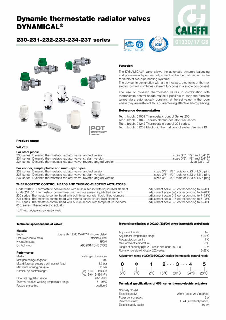
The DYNAMICAL® valve allows the automatic dynamic balancing and pressure-independent adjustment of the thermal medium in the radiators of two-pipe heating systems.The device, in conjunction with a thermostatic, electronic or thermo-electric control, combines different functions in a single component.
The use of dynamic thermostatic valves in combination with thermostatic control heads makes it possible to keep the ambient temperature automatically constant, at the set value, in the room where they are installed, thus guaranteeing effective energy saving.
Reference documentation
Tech. broch. 01009 Thermostatic control Series 200Tech. broch. 01042 Thermo-electric actuator 656. series.Tech. broch. 01242 Thermostatic control 204 series.Tech. broch. 01263 Electronic thermal control system Series 210
ACCREDITED
ISO 9001 FM 21654
0 1❄ 2 ∙ ∙ ∙ ∙ ∙ ∙3 4 5
7°C5°C 12°C 16°C 20°C 24°C 28°C
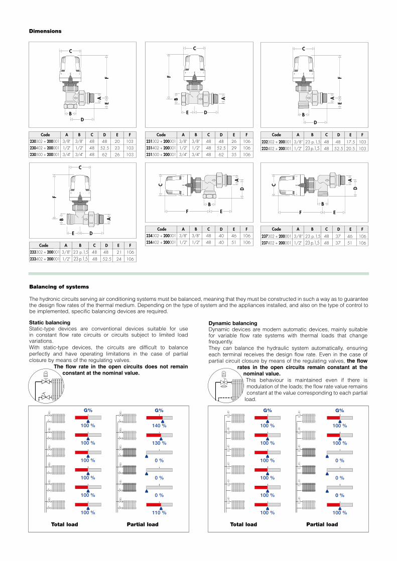
Dimensions
C
B
F
AD
43
··
··
··2
E
C
BF
AD
43
··
··
··2
E
C
A
FB
D
4 3· · · · · · 2
E
C
A
EF
BD
4 3· · · · · · 2
8030 p.1,5 48
4 3· · · · · · 2
8030 p.1,5 48
B
A
C
D
E
33 95
G
F
200001201000
80
80
30 p.1,5
30 p.1,5
48
48
Ø 11
Ø 9.5
158
134
203502
203702
1/2"
Ø13
187
C
A
FB
D
4 3· · · · · · 2
E
C
A
EF
B
D
4 3· · · · · · 2
A
3/8"
1/2"
3/4"
B
3/8"
1/2"
3/4"
C
48
48
48
Code
230302 + 200001
230402 + 200001
230500 + 200001
E
20
23
26
D
48
52.5
62
F
103
103
103
A
3/8"
1/2"
3/4"
B
3/8"
1/2"
3/4"
C
48
48
48
Code
231302 + 200001
231402 + 200001
231500 + 200001
E
26
29
35
D
48
52.5
62
F
106
106
106
A
3/8"
1/2"
B
3/8"
1/2"
C
48
48
Code
234302 + 200001
234402 + 200001
E
46
51
D
40
40
F
106
106
1/2" 23 p.1,5 48233402 + 200001 2452.5 106
HCode
475002
475003
H
11.5
10
A
1/2"
B
23 p.1,5
C
48
Code
232402 + 200001
E
20.5
D
52.5
F
103
3/8" 23 p.1,5 48232302 + 200001 17.5 48 103
A
1/2"
B
23 p.1,5
C
48
Code
237402 + 200001
E
51
D
37
F
106
3/8" 23 p.1,5 48237302 + 200001 46 37 106
A B CCode ED F
3/8" 23 p.1,5 48233302 + 200001 21 48 106
BA C D ECode F G
A
30 p. 1,5
B
74
74
C
48
48
Code
199000
199100
D
3330 p. 1,5
E
95A
30 p. 1,5
B
85C
48
Code
202000
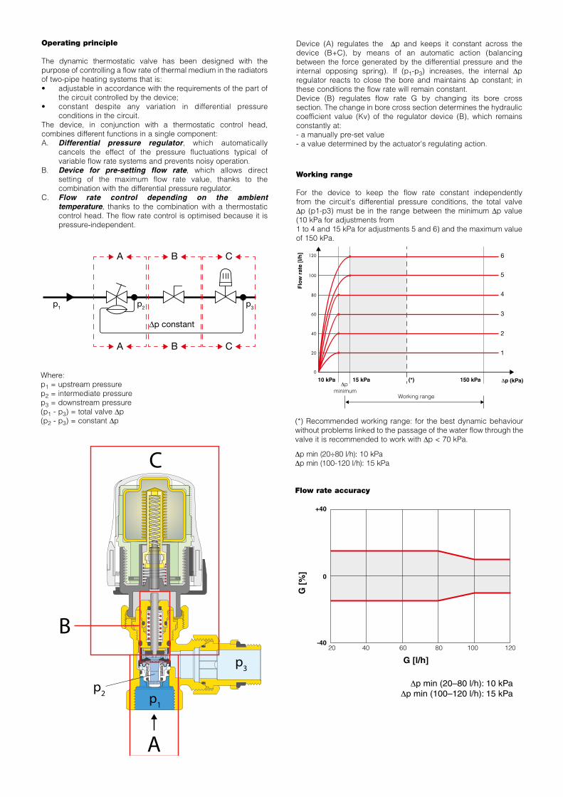
Static balancingStatic-type devices are conventional devices suitable for use in constant flow rate circuits or circuits subject to limited load variations.With static-type devices, the circuits are difficult to balance perfectly and have operating limitations in the case of partial closure by means of the regulating valves. The flow rate in the open circuits does not remain
constant at the nominal value.
Dynamic balancingDynamic devices are modern automatic devices, mainly suitable for variable flow rate systems with thermal loads that change frequently. They can balance the hydraulic system automatically, ensuring each terminal receives the design flow rate. Even in the case of partial circuit closure by means of the regulating valves, the flow
rates in the open circuits remain constant at the nominal value.This behaviour is maintained even if there is modulation of the loads; the flow rate value remains constant at the value corresponding to each partial
load.
Total load Total loadPartial load Partial load
140 %
130 %
0 %
0 %
0 %
110 %
100 %
100 %
100 %
100 %
100 %
100 %
G% G%
100 %
100 %
100 %
100 %
100 %
100 %
100 %
100 %
0 %
0 %
0 %
100 %
G% G%
140 %
130 %
0 %
0 %
0 %
110 %
100 %
100 %
100 %
100 %
100 %
100 %
G% G%
100 %
100 %
100 %
100 %
100 %
100 %
100 %
100 %
0 %
0 %
0 %
100 %
G% G%
Balancing of systems
The hydronic circuits serving air conditioning systems must be balanced, meaning that they must be constructed in such a way as to guarantee the design flow rates of the thermal medium. Depending on the type of system and the appliances installed, and also on the type of control to be implemented, specific balancing devices are required.
140 %
130 %
0 %
0 %
0 %
110 %
100 %
100 %
100 %
100 %
100 %
100 %
G% G%
100 %
100 %
100 %
100 %
100 %
100 %
100 %
100 %
0 %
0 %
0 %
100 %
G% G%
140 %
130 %
0 %
0 %
0 %
110 %
100 %
100 %
100 %
100 %
100 %
100 %
G% G%
100 %
100 %
100 %
100 %
100 %
100 %
100 %
100 %
0 %
0 %
0 %
100 %
G% G%
Operating principle
The dynamic thermostatic valve has been designed with the purpose of controlling a flow rate of thermal medium in the radiators of two-pipe heating systems that is:• adjustable in accordance with the requirements of the part of
the circuit controlled by the device;• constant despite any variation in differential pressure
conditions in the circuit.The device, in conjunction with a thermostatic control head, combines different functions in a single component:A. Differential pressure regulator, which automatically
cancels the effect of the pressure fluctuations typical of variable flow rate systems and prevents noisy operation.
B. Device for pre-setting flow rate, which allows direct setting of the maximum flow rate value, thanks to the combination with the differential pressure regulator.
C. Flow rate control depending on the ambient temperature, thanks to the combination with a thermostatic control head. The flow rate control is optimised because it is pressure-independent.
Device (A) regulates the Dp and keeps it constant across the device (B+C), by means of an automatic action (balancing between the force generated by the differential pressure and the internal opposing spring). If (p1-p3) increases, the internal Dp regulator reacts to close the bore and maintains Dp constant; in these conditions the flow rate will remain constant.Device (B) regulates flow rate G by changing its bore cross section. The change in bore cross section determines the hydraulic coefficient value (Kv) of the regulator device (B), which remains constantly at:- a manually pre-set value- a value determined by the actuator's regulating action.
Working range
For the device to keep the flow rate constant independently from the circuit's differential pressure conditions, the total valve Dp (p1-p3) must be in the range between the minimum Dp value (10 kPa for adjustments from 1 to 4 and 15 kPa for adjustments 5 and 6) and the maximum value of 150 kPa.
Where:p1 = upstream pressurep2 = intermediate pressurep3 = downstream pressure(p1 - p3) = total valve Dp(p2 - p3) = constant Dp
∆p constant
A
p1 p2 p3
A
B
B
C
C
A
B
C
p1
p3
p2
Flo
w r
ate
[l/h
]
0
20
40
60
80
100
120 6
5
4
3
2
1
Δp minimum
G6
G8
G10
Δp (kPa)
Δp (kPa)
G1
25 kPa 30 kPa
Δp minimum
10 kPa 15 kPa 150 kPa(*)
400 kPa
G (m3/h)
Working range
Working range
G [%
]
0
+40
-40
G [l/h]
Δp min (20–80 l/h): 10 kPaΔp min (100–120 l/h): 15 kPa
20 40 60 80 100 120
(*) Recommended working range: for the best dynamic behaviour without problems linked to the passage of the water flow through the valve it is recommended to work with Dp < 70 kPa.
Δp min (20÷80 l/h): 10 kPaΔp min (100-120 l/h): 15 kPa
Flow rate accuracy
System sizing
For correct system sizing, the valves are normally selected by determining the pre-setting value based on the design flow rate on the diagram with thermostatic control head and 2K proportional band.
Stepped adjustement, not continuos.
GN
um. -
Max
imum
flow
rate
[l/h
]
10 15 20 40 60 80 100 120 140 150
∆p [kPa]
0
20
40
60
80
100
120 6
5
4
3
2
1
G2K
- Fl
ow ra
te (2
K) [l
/h]
10 15 20 40 60 80 100 120 140 150
∆p [kPa]
0
20
40
55
8070
90100
120
6
5
4
3
2
1
Hydraulic characteristics
Without thermostatic control head With thermostatic control head and 2K proportional band
Ease of designThe presence of the internal device which is able to regulate the flow rate and stabilise the working Dp allows faster design and balancing operations: no support components are required for calculations and pre-setting is very simple.
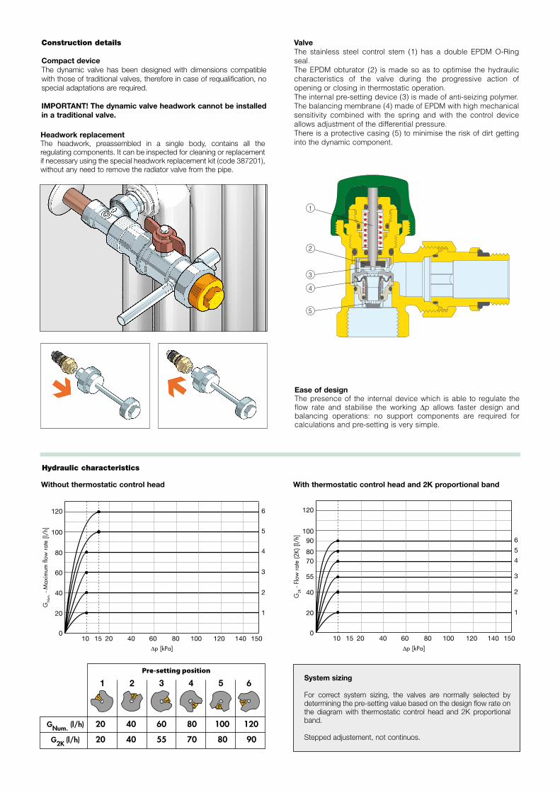
ValveThe stainless steel control stem (1) has a double EPDM O-Ring seal.The EPDM obturator (2) is made so as to optimise the hydraulic characteristics of the valve during the progressive action of opening or closing in thermostatic operation. The internal pre-setting device (3) is made of anti-seizing polymer.The balancing membrane (4) made of EPDM with high mechanical sensitivity combined with the spring and with the control device allows adjustment of the differential pressure.There is a protective casing (5) to minimise the risk of dirt getting into the dynamic component.
1
2
3
4
5
GNum. (l/h)
G2K (l/h)
10080604020 120
8070554020 90
62 3
4 5 6
1
Pre-setting position
Construction details
Compact device The dynamic valve has been designed with dimensions compatible with those of traditional valves, therefore in case of requalification, no special adaptations are required.
IMPORTANT! The dynamic valve headwork cannot be installed in a traditional valve.
Headwork replacement The headwork, preassembled in a single body, contains all the regulating components. It can be inspected for cleaning or replacement if necessary using the special headwork replacement kit (code 387201), without any need to remove the radiator valve from the pipe.
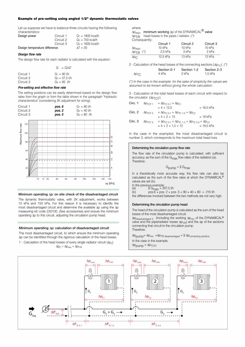
Let us suppose we have to balance three circuits having the following characteristics:Design power Circuit 1 Q1 = 1800 kcal/h Circuit 2 Q2 = 750 kcal/h Circuit 3 Q3 = 1600 kcal/hDesign temperature difference DT = 20
Design flow rate
The design flow rate for each radiator is calculated with the equation:
G = Q/DT
Circuit 1 G1 = 90 l/h Circuit 2 G2 = 37,5 l/h Circuit 3 G3 = 80 l/h
Pre-setting and effective flow rate
The setting positions can be easily determined based on the design flow rates from the graph or from the table shown in the paragraph "Hydraulic characteristics" (considering 2K adjustment for sizing).
Circuit 1 pos. 6 G1 = 90 l/h Circuit 2 pos. 2 G2 = 40 l/hCircuit 3 pos. 5 G3 = 80 l/h
Example of pre-setting using angled 1/2” dynamic thermostatic valves
where: Dpmin minimum working Dp of the DYNAMICAL® valve DpT/R head losses in the pipes / radiator. (*) Consequently: Circuit 1 Circuit 2 Circuit 3 Dpmin 10 kPa 10 kPa 10 kPa DpT/R (*) 2,5 kPa 3 kPa 2 kPa
DpC 12,5 kPa 13 kPa 12 kPa
2 - Calculation of the head losses of the connecting sections (DpTC). (*)
Section 0-1 Section 1-2 Section 2-3 DpTC 4 kPa 2 kPa 1,5 kPa
(*) In the case in the example, for the sake of simplicity the values are assumed to be known without giving the whole calculation.
3 - Calculation of the total head losses of each circuit with respect to the circulator. (DpTOT).
Circ. 1 DpTOT 1 = DpTC 0-1 + DpC1 = 4 + 12,5 = 16,5 kPaCirc. 2 DpTOT 2 = DpTC 0-1 + DpTC 1-2 + DpC2 = 4 + 2 + 13 = 19 kPaCirc. 3 DpTOT 3 = DpTC 0-1 + DpTC 1-2 + DpTC 2-3 + DpC3 = 4 + 2 + 1,5 + 12 = 19,5 kPa
In the case in the exampled, the most disadvantaged circuit is number 3, which corresponds to the maximum total head loss.
Max
imum
flow
rate
10 15 20 40 60 80 100 120 140 150
∆p [kPa]
0
20
40
60
80
100
120
6
5
4
3
2
1
Minimum operating Dp: on site check of the disadvantaged circuit
The dynamic thermostatic valve, with 2K adjustment, works between 10 kPa and 150 kPa. For this reason it is necessary to identify the most disadvantaged circuit and determine the available Dp using the Dp measuring kit code 230100. (See accessories) and ensure the minimum operating Dp to this circuit, adjusting the circulation pump head.
Minimum operating Dp: calculation of disadvantaged circuit
The most disadvantaged circuit, to which ensure the minimum operating Dp can be identified through the rigorous calculation of the head losses.
1 - Calculation of the head losses of every single radiator circuit (DpC)DpC = Dpmin + DpT/R
GTot.
G1
1
Δpmin1
ΔPTOT G2 + G3 G3
ΔPTC 2-3ΔPTC 1-2ΔPTC 0-1
ΔpT/R1
ΔpC1
G2
2
Δpmin2 ΔpT/R2
ΔpC2
G3
3
Δpmin3 ΔpT/R3
ΔpC3
Determining the circulation pump flow rate
The flow rate of the circulation pump is calculated, with sufficient accuracy, as the sum of the Gmax flow rates of the radiators (a).Therefore:
Gpump = S Gmax
In a theoretically more accurate way, the flow rate can also be calculated as the sum of the flow rates at which the DYNAMICAL® valves are set (b).In the previous example:(a) S Gmax = 207,5 l/h(b) pos.6 + pos. 2 + pos. 5 = 90 + 40 + 80 = 210 l/hthe differences involved between the two methods are not very high.
Determining the circulation pump head
The head of the circulation pump is calculated as the sum of the head losses of the most disadvantaged circuit. DpDisadvantaged C (including the working Dpmin of the DYNAMICAL®
valve and the pipe/radiator losses DpT/R) and the Dp of the sections connecting that circuit to the circulation pump.Therefore:
Dppump= Dpmin +DpT/R disadvantaged + S Dpconnecting sections
In the case in the example:Dppump = DpTOT3
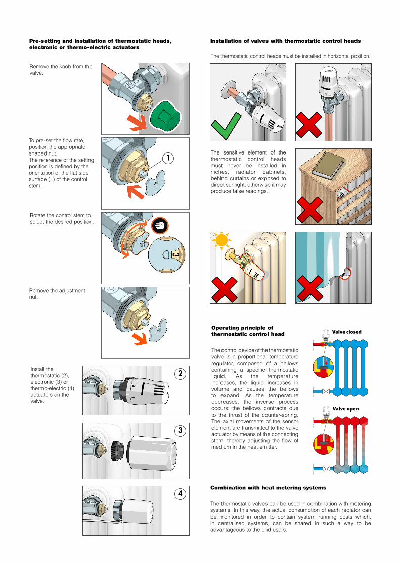
Pre-setting and installation of thermostatic heads, electronic or thermo-electric actuators
Installation of valves with thermostatic control heads
Remove the knob from the valve.
The thermostatic control heads must be installed in horizontal position.
The sensitive element of the thermostatic control heads must never be installed in niches, radiator cabinets, behind curtains or exposed to direct sunlight, otherwise it may produce false readings.
Remove the adjustment nut.
To pre-set the flow rate, position the appropriate shaped nut.The reference of the setting position is defined by the orientation of the flat side surface (1) of the control stem.
Rotate the control stem to select the desired position.
Install the thermostatic (2), electronic (3) or thermo-electric (4) actuators on the valve.
2
1
4
3
Valve closed
Valve open
Operating principle of thermostatic control head
The control device of the thermostatic valve is a proportional temperature regulator, composed of a bellows containing a specific thermostatic liquid. As the temperature increases, the liquid increases in volume and causes the bellows to expand. As the temperature decreases, the inverse process occurs; the bellows contracts due to the thrust of the counter-spring. The axial movements of the sensor element are transmitted to the valve actuator by means of the connecting stem, thereby adjusting the flow of medium in the heat emitter.
Combination with heat metering systems
The thermostatic valves can be used in combination with metering systems. In this way, the actual consumption of each radiator can be monitored in order to contain system running costs which, in centralised systems, can be shared in such a way to be advantageous to the end users.
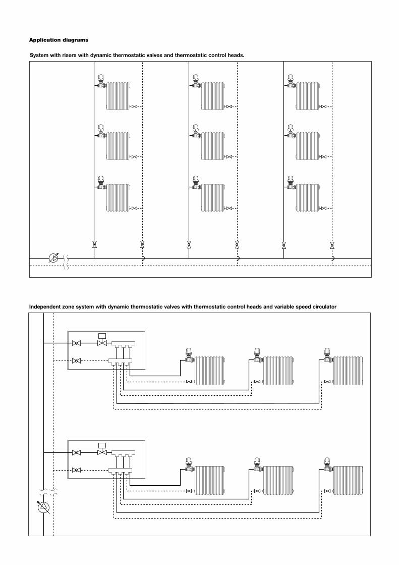
Independent zone system with dynamic thermostatic valves with thermostatic control heads and variable speed circulator
Application diagrams
System with risers with dynamic thermostatic valves and thermostatic control heads.
230 seriesDynamic thermostatic radiator valve fitted for thermostatic control heads, electronic and thermo-electric actuators. Angled connections for steel pipe. Connection to the radiator 3/8” or 1/2” M with tailpiece supplied with EPDM seal, 3/4” with tailpiece without seal. Brass body. Chrome plated. Knob in ABS green PANTONE 356C, for manual control. Stainless steel control stem. Double seal on control stem with EPDM O-Ring. Medium working temperature range 5–95°C. Maximum working pressure 10 bar. PCT - INTERNATIONAL APPLICATION PENDING. 231 series Dynamic thermostatic radiator valve fitted for thermostatic control heads, electronic and thermo-electric actuators. Straight connections for steel pipe. Connection to the radiator 3/8” or 1/2” M with tailpiece supplied with EPDM seal, 3/4” with tailpiece without seal. Brass body. Chrome plated. Green PANTONE 356C ABS knob for manual control. Stainless steel control stem. Double seal on control stem with EPDM O-Ring. Medium working temperature range 5–95°C. Maximum working pressure 10 bar. PCT - INTERNATIONAL APPLICATION PENDING. 232 series Dynamic thermostatic radiator valve fitted for thermostatic control heads, electronic and thermo-electric actuators. Angled connections for copper, plastic and multilayer pipes 23 p.1,5 for pipes from 10 to 18 mm. Connection to radiator 3/8” and 1/2” M with tailpiece equipped with EPDM seal. Brass body. Chrome plated. Knob in ABS green PANTONE 356C, for manual control. Stainless steel control stem. Double seal on control stem with EPDM O-Ring. Medium working temperature range 5–95°C. Maximum working pressure 10 bar. PCT - INTERNATIONAL APPLICATION PENDING.
233 series Dynamic thermostatic radiator valve fitted for thermostatic control heads, electronic and thermo-electric actuators. Straight connections for copper, plastic and multilayer pipes 23 p.1,5 for pipes from 10 to 18 mm. Connection to radiator 3/8” and 1/2” M with tailpiece equipped with EPDM seal. Brass body. Chrome plated. Knob in ABS green PANTONE 356C, for manual control. Stainless steel control stem. Double seal on control stem with EPDM O-Ring. Medium working temperature range 5–95°C. Maximum working pressure 10 bar. PCT - INTERNATIONAL APPLICATION PENDING.
234 seriesReverse-angled dynamic thermostatic radiator valve fitted for thermostatic control heads, electronic and thermo-electric actuators. For steel pipes. Connection to radiator 3/8” and 1/2” M with tailpiece equipped with EPDM seal. Brass body. Chrome plated. Knob in ABS green PANTONE 356C, for manual control. Stainless steel control stem. Double seal on control stem with EPDM O-Ring. Medium working temperature range 5–95°C. Maximum working pressure 10 bar. PCT - INTERNATIONAL APPLICATION PENDING. 237 series Reverse-angled dynamic thermostatic radiator valve fitted for thermostatic control heads, electronic and thermo-electric actuators. For copper, simple plastic and multilayer pipes 23 p.1,5 for pipes from 10 to 18 mm. Connection to radiator 3/8” and 1/2” M with tailpiece equipped with EPDM seal. Brass body. Chrome plated. Knob in ABS green PANTONE 356C, for manual control. Stainless steel control stem. Double seal on control stem with EPDM O-Ring. Medium working temperature range 5–95°C. Maximum working pressure 10 bar. PCT - INTERNATIONAL APPLICATION PENDING.
SPECIFICATION SUMMARIES
We reserve the right to make changes and improvements to the products and related data in this publication, at any time and without prior notice.
Caleffi S.p.A.S.R. 229 n. 25 · 28010 Fontaneto d’Agogna (NO) · ItalyTel. +39 0322 8491 · Fax +39 0322 [email protected] · www.caleffi.com© Copyright 2017 Caleffi
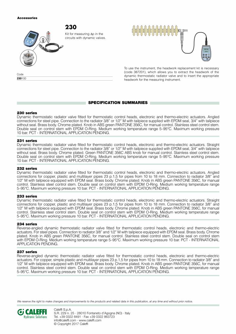
Accessories
230Kit for measuring Δp in the circuits with dynamic valves.
To use the instrument, the headwork replacement kit is necessary (code 387201), which allows you to extract the headwork of the dynamic thermostatic radiator valve and to insert the appropriate headwork for the measuring instrument.
AUTO/OFFESC
CLRDATA
UNIT RELHOLD
ENTER
ZERO
0014000020
Code230100