dynamical system - arxiv · bead on a rotating circular hoop: a simple yet feature-rich dynamical...
TRANSCRIPT

Bead on a rotating circular hoop: a simple yet feature-rich
dynamical system
Shovan Dutta1 and Subhankar Ray2
1 Department of Electronics and Telecommunication Engineering,
Jadavpur University, Calcutta 700 032, India and
2 Department of Physics, Jadavpur University, Calcutta 700 032, India
The motion of a bead on a rotating circular hoop is investigated using elementary
calculus and simple symmetry arguments. The peculiar trajectories of the bead at
different speeds of rotation of the hoop are presented. Phase portraits and nature of
fixed points are studied. Bifurcation is observed with change in the rotational speed
of the hoop. At a critical speed of rotation of the hoop, there appears an interesting
relation between the time period and amplitude of oscillation of the bead. The
study introduces several important aspects of nonlinear dynamics. It is suitable for
students having basic understanding in elementary calculus and classical mechanics.
PACS numbers: 05.45.-a, 45.20.dg, 03.65.Ge, 11.30.Qc
arX
iv:1
112.
4697
v1 [
phys
ics.
clas
s-ph
] 1
3 D
ec 2
011

2
I. INTRODUCTION
A bead moving on a rotating circular hoop is a classic example studied in several text-
books on classical mechanics1–3 and nonlinear dynamics. It exhibits various modes of mo-
tion, including some peculiar ones, such as, oscillations confined to one side of the hoop
and complete revolutions, for appropriate initial conditions. It also shows a wide array of
features of dynamical systems. It is useful for demonstrating different classes of fixed points,
bifurcations, reversibility, symmetry breaking, critical slowing down, trapping regions, ho-
moclinic and heteroclinic orbits and Lyapunov functions. It is also an interesting example of
a constrained system, illustrating the use of Lagrange multipliers for determining constraint
forces.
In this article we investigate in detail, the dynamics of this bead-hoop system. The
number and nature of equilibrium points alter with change in speed of rotation of the hoop.
This results in some extraordinary modes of motion, phase trajectories and bifurcations. At
a critical speed of rotation of the hoop, an interesting relation between the time period and
amplitude of oscillation of the bead is observed.
Our study is based on elementary calculus and simple symmetry arguments. A student
reader with a background of classical mechanics and basic calculus will find the study both
accessible and interesting.
The article is organized as follows. In section II, the physical system is described. The
equation of motion of the system is derived from the Lagrangian. In section III, the effective
potential is analyzed to find the equilibrium positions of the bead for all possible speeds of
rotation of the hoop. The distinct modes of motion of the bead for different initial conditions
are described and numerical plots of its trajectories are presented. The constraint forces are
determined from the method of Lagrange multipliers in section IV. In section V, the nature
of the fixed points of the system are analyzed from symmetry properties of the system. The
phase trajectories and bifurcations are examined. Finally, we conclude with a discussion on
connections to other systems in section VI.

3
II. THE PHYSICAL SYSTEM
A bead of mass m, moves without friction on a circular hoop of radius a. The hoop
rotates about its vertical diameter with a constant angular velocity ω. The position of the
bead on the hoop is given by angle θ, measured from the vertically downward direction (−z
axis), and φ is the angular displacement of the hoop from its initial position on the x-axis (
Figure 1).
Φ
Θ
Ω
x
z
y
FIG. 1. Schematic diagram for bead on the hoop
The kinetic and potential energies of the bead are given by,
T =1
2ma2(θ2 + sin2 θφ2) and V = −mga cos θ , (1)
respectively, where g is the magnitude of the acceleration due to gravity. The Lagrangian
of the system is,
L(θ, θ) =ma2
2(θ2 + ω2 sin2 θ) +mga cos θ , where ω = φ (a constant). (2)
Using the Euler-Lagrange equation, the equation of motion is obtained as,
θ = sin θ(ω2 cos θ − g/a). (3)
Denoting ω2c = g/a, k = ω2/ω2
c and defining τ = ωc t, the equation of motion may be written
in dimensionless form as,
θ′′
= sin θ(k cos θ − 1) , where θ′′
=d2θ
dτ 2. (4)
The symmetry of the system about the vertical axis manifests in the invariance of the equa-
tion of motion when θ is changed to −θ. The system also exhibits time reversal symmetry
as (4) is invariant under the transformation τ → −τ .

4
Let us denote v = θ′
and write (4) as,
vdv
dθ= − sin θ + k sin θ cos θ, (5)
which upon integration yields,
1
2v2 = cos θ − k
4cos 2θ + A, (6)
where A is a constant of integration. We can identify a conserved quantity, ε as,
ε =1
2θ′2 − 1
2k sin2 θ − cos θ . (7)
It may be termed as the effective energy that corresponds to the system described by (4).
However, it is to be noted that, the mechanical energy of the original bead-hoop system
is not conserved due to the work done in preserving the constant angular velocity of the
hoop. Equation (7) provides a natural separation of the effective energy into effective kinetic
energy 12θ′2
and effective potential energy, U(θ), given by,
U(θ) = −1
2k sin2 θ − cos θ . (8)
As U(θ) is an even function of θ, we restrict our attention to θ ∈ [0, π]. θ′2
is completely
determined by θ and ε. The sign of θ′, however, cannot be determined uniquely from (7).
The parameter k grows with increasing angular velocity ω of the hoop and k = 0 implies
that the hoop is stationary.
It is useful to consider the first and second derivatives of U(θ),
U′(θ) =
dU
dθ= − sin θ(k cos θ − 1) , and (9)
U′′(θ) =
d2U
dθ2= −(k cos 2θ − cos θ) . (10)
Comparison of (4) and (9) shows that,
θ′′
= −U ′(θ) = − sin θ(1− k cos θ) . (11)
The effective potential has two extrema at θ = 0 and θ = π, where the first derivative of the
potential vanishes. Evaluating the second derivative at these points, one finds that θ = 0 is
a minimum (U′′(0) > 0) and θ = π is a maximum (U
′′(0) < 0) of the effective potential as
shown in Figure 2. Due to the right-left symmetry of the hoop, one concludes, θ = −π is
also a maximum point of the effective potential. At these points the values of the effective
potential are U(0) = Umin = −1 and U(±π) = Umax = 1.
5
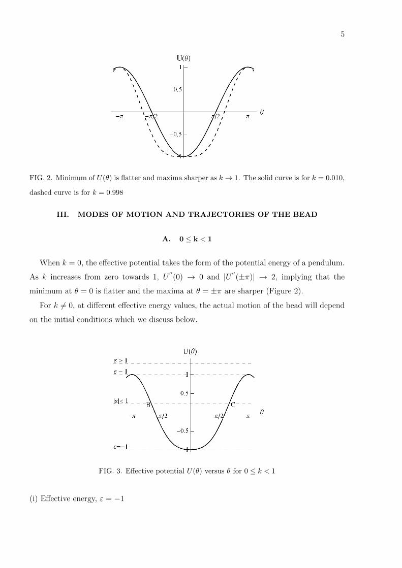
FIG. 2. Minimum of U(θ) is flatter and maxima sharper as k → 1. The solid curve is for k = 0.010,
dashed curve is for k = 0.998
III. MODES OF MOTION AND TRAJECTORIES OF THE BEAD
A. 0 ≤ k < 1
When k = 0, the effective potential takes the form of the potential energy of a pendulum.
As k increases from zero towards 1, U′′(0) → 0 and |U ′′(±π)| → 2, implying that the
minimum at θ = 0 is flatter and the maxima at θ = ±π are sharper (Figure 2).
For k 6= 0, at different effective energy values, the actual motion of the bead will depend
on the initial conditions which we discuss below.
FIG. 3. Effective potential U(θ) versus θ for 0 ≤ k < 1
(i) Effective energy, ε = −1

6
θ′2
= 2(ε − U(θ)) must be positive, hence the lower bound of ε is equal to the minimum
value of U(θ) which is −1 (Figure 3). This corresponds to the initial condition θ(0) = 0 and
θ′(0) = 0. From (11) however, θ
′′= 0 as well, independent of the value of k. Hence, the
bead stays at the bottom of the hoop (θ = 0) for all times.
(ii) −1 < ε < 1
The angular position θ of the bead oscillates between −θ0 and +θ0, corresponding to the
turning points B and C shown in Figure 3. At these points θ′= 0, and the effective potential
equals the effective energy. From (4), θ′′< 0 and this restoring acceleration ensures that θ
FIG. 4. Out of phase oscillation of θ′
and θ′′
for k = 0.75, θ0 = 2π/3
approaches 0. At θ = 0, acceleration θ′′
is zero, whereas the velocity θ′
attains its maximum
magnitude. Hence, the bead slides past the bottom of the hoop and θ decreases further,
becoming negative. When θ < 0, θ′′
becomes positive, and this acceleration reduces the
magnitude of θ′, making it zero at −θ0. θ
′′remains nonzero and positive at −θ0. The
acceleration θ′′
is positive for all negative values of θ. At θ = −θ0, θ′′> 0 and velocity is
momentarily zero. From the next instant, velocity begins to increase as θ′′> 0. Thus θ
′and

7
θ′′
oscillate out of phase with each other as shown in Figure 4. At −θ0, θ′′> 0, θ
′becomes
positive, θ begins to increase. The bead retraces its path reaching θ0 and the process is
repeated. The amplitude of oscillation increases with ε. The time period of the oscillation
of the bead between ±θ0 is given by,
T = 4
∫ θ0
0
d θ√(cos θ − cos θ0)(2− k(cos θ + cos θ0))
. (12)
Figure 5 shows the trajectory of the bead after the elapse of different time intervals, with
k = 3/4 and amplitude θ0 = 2π/3. As the bead goes through half an oscillation (with
amplitude 2π/3 and k = 3/4), the hoop rotates through an angle given by,
∆φ = ω
(√a
g
T
2
)=
√k
2T = 3.539 radians .
-1-0.5
0
0.5
1
-0.5
0
0.5
1
-1
-0.5
0
0.5
-1-0.5
0
0.5
-0.5
0
0.5
1
(a) τ = 28
-1-0.5
00.5
1
-1
-0.5
0
0.51
-1
-0.5
0
0.5
-1-0.5
00.5
1
-1
-0.5
0
0.51
(b) τ = 62.5
-1 -0.5 0 0.5 1-1
-0.5
0
0.5
1
-1-0.5
0
0.5
(c) τ = 62.5, top view
FIG. 5. Trajectory for k=0.75, θ(0) = 2π/3, θ′(0) = 0 at different τ values
(iii) ε = 1
At θ = ±π, the effective potential energy is also +1. Thus the effective kinetic energy and
θ′
is zero. From the expression of acceleration in (4), we find θ′′
= 0 at θ = ±π. This agrees
with the fact that θ = ±π are the position of maximum potential energy. From (7), we
obtain,
θ′2
= 4 cos2 θ
2[1 + k sin2 θ
2] . (13)
The time taken to reach the highest point (θ = π) from an initial point θ0 may be computed
as,
T =1
2
∫ π
θ0
d θ
cos (θ/2)√
1 + k sin2 (θ/2)(14)

8
The integral can be transformed with the substitution u = π − θ, as,
T =1
2
∫ π−θ0
0
d u
sin (u/2)√
1 + k cos2 (u/2)(15)
In the neighbourhood of u = 0, corresponding to θ close to π, the integrand behaves as
(1+k)−1/2
uand hence, the integral diverges. This implies that the bead approaches θ = π
infinitesimally slowly and takes an infinite amount of time to reach the top of the hoop
(Figure 6). By virtue of time-reversal symmetry and the left-right symmetry of the hoop,
00.5
1-0.5
0
-1
-0.5
0
0.5
1
-0.5
0
FIG. 6. Trajectory for k = 0.75, θ(0) = 2π/3 and ε = 1
for θ′(0) < 0, the bead reaches the bottom where θ
′has the maximum magnitude of 2 (from
(7)) and then asymptotically approaches θ = −π at ever-decreasing speed.
(iv) ε > 1
As the maximum value of U(θ) = 1, ε− U(θ) > 0 and hence θ′
is not zero for any θ. Thus
if the bead starts initially with θ′(0) > 0 and at a position θ(0) ∈ (0, π), then θ
′′(0) < 0 and
θ′
starts to decrease. θ′
attains its minimum value when the bead reaches θ = π. At this
position, θ′′
= 0, however, θ′
is not zero and θ continues to increase. Hence the bead moves
past the top of the loop. For θ ∈ (π, 3π2
), θ′′
is positive and θ′increases, becoming maximum
when the bead reaches the bottom of the hoop. Thus θ increases or decreases indefinitely,
depending on the sign of θ′(0) and the bead slides over the entire hoop periodically (Figure
7). For θ′(0) < 0, the same rotation occurs in the opposite sense. The maximum and
minimum values of θ′
can be calculated from the expression of the effective energy. The
time period of rotation is given by,
T = 2
∫ π
0
d θ√(θ′(0))2 − (cos θ − cos θ0)[2− k(cos θ + cos θ0)]
(16)

9
When |θ′(0)| is very large, nearly all the energy of the bead is the kinetic energy of rotation.
Hence the influence of gravity becomes small in comparison, and this rotation may be
considered to be uniform. In this limit, the time period approaches the value 2π/|θ′(0)|.
-1-0.5
00.5
-1
-0.5
00.5
1
-1
-0.5
0
0.5
1
-1-0.5
00.5
-1
-0.5
00.5
1
(a) τ = 20
-1-0.5
00.5
1
-1
-0.5
00.5
1
-1
-0.5
0
0.5
1
-1-0.5
00.5
1
-1
-0.5
00.5
1
(b) τ = 40
-1-0.5
00.5
1
-1
-0.5
00.5
1
-1
-0.5
0
0.5
1
-1-0.5
00.5
1
-1
-0.5
00.5
1
(c) τ = 200
FIG. 7. Trajectory for k=0.01, θ(0) = 2π/3, θ′(0) = 1.4 for different τ .
B. k = 1
U(θ) is maximum at θ = π as before. However, at θ = 0, both U′(0) and U
′′(0) vanish.
On expanding U(θ) about θ = 0, we get,
U(θ) = −1 +θ4
8+ O(θ6) .
For |θ| ≥ 0, in the neighbourhood of θ = 0, U(θ) is always greater than U(0). Hence θ = 0 is
a minimum of the potential. The potential is more flat than for the case k < 1. Depending
on the values of ε, the bead can undergo all the types of motion described in the previous
subsection. However, for oscillatory motion, the period of oscillation for a given amplitude
is larger when k = 1 than when k < 1. This becomes clear if (4) is expanded in the vicinity
of θ = 0,
θ′′
= (θ − θ3
3!+ ...)[k(1− θ2
2!+ ...)− 1]
= −(1− k)θ −(
2k3− 1
6
)θ3 + O(θ5)
When k < 1, θ′′ ∼ O(θ), however, for k = 1, θ
′′ ∼ O(θ3). For small amplitude θ (θ → 0),
θ′′
k=1(∼ O(θ3)) is much smaller than θ′′
k<1(∼ O(θ)). Thus θ′
changes much more slowly in the

10
neighbourhood of θ = 0 for k = 1. Consequently, the period of oscillation T , for the same
amplitude is significantly larger.
TABLE I. Time period of oscillations for different amplitudes at various k values.
T about θ = 0 k = 0 k = 0.5 k = 0.75 k = 1
amplitude π/10 6.32 8.78 12.00 33.71
amplitude = π/20 6.29 8.86 12.41 66.93
amplitude = π/40 6.29 8.88 12.53 133.62
amplitude = π/80 6.28 8.88 12.55 267.12
Table I lists the time periods computed for different amplitudes at various values of k.
The values in the table reveal a very interesting pattern. For small amplitudes, the time
period is essentially independent of amplitude when 0 ≤ k < 1; but for k = 1, the time
period increases inversely as the decrease in amplitude. This is explained as follows. For
0 ≤ k < 1, the effective potential is approximately parabolic in the neighbourhood of θ = 0,
analogous to the simple pendulum. Thus, the small amplitude motion of the bead is simple
harmonic, for which the time period is independent of amplitude. However, this parabolic
approximation does not hold when k = 1, as the second derivative of the effective potential,
U′′(θ), vanishes at θ = 0. Using (12), the time period of oscillation for k = 1 can be
calculated as follows,
T = 4
∫ θ0
0
d θ√(cos θ − cos θ0)(2− cos θ − cos θ0)
. (17)
Expanding the integrand for small θ0 gives,
T = 4
∫ θ0
0
d θ√(θ20−θ2
2!− θ40−θ4
4!+
θ60−θ66!
+ . . . )(θ20+θ2
2!− θ40+θ4
4!+
θ60+θ6
6!+ . . . )
Retaining terms up to eighth order in θ0,
T = 4
∫ θ0
0
d θ√14(θ4
0 − θ4)− 124
(θ60 − θ6) + 1
320(θ8
0 − θ8)
=8
θ20
∫ θ0
0
d θ√1− ( θ
θ0)4 − θ20
6(1− ( θ
θ0)6) +
θ4080
(1− ( θθ0
)8)

11
Defining a new variable y = θ/θ0, this can be expressed as,
T =8
θ0
∫ 1
0
d y√1− y4 − θ20
6(1− y6) +
θ4080
(1− y8)
=8
θ0
∫ 1
0
d y√1− y4
[1− θ2
0
6
1− y6
1− y4+θ4
0
80
1− y8
1− y4
]−1/2
Expanding the quantity within brackets in a binomial series and retaining terms upto fourth
order in θ0,
T =A
θ0
+Bθ0 + Cθ30 +O(θ5
0) (18)
where the constants are given by,
A = 8
∫ 1
0
dy√1− y4
= 10.49 (19)
B =2
3
∫ 1
0
1− y6
(1− y4)3/2dy = 1.04 (20)
C =
∫ 1
0
(1
12
(1− y6)2
(1− y4)5/2− 1
20
1− y8
(1− y4)3/2
)dy = 0.07 (21)
This shows that for small θ0, T ≈ A/θ0, which explains why T doubles when the amplitude
is halved. Equation (18) gives a very good approximation even if θ0 is not close to 0, e.g.,
for θ0 = π/2, the error is only −0.58% (Figure 8). This can be accounted for by noting that
the coefficients of higher order terms in θ0 decrease rapidly. Thus the expansion converges
very fast. As an example, for θ0 = 1, the third term in (18) contributes only about 0.67%
of the first term. Another point to be noted is that the time period of oscillation for k = 0,
increases with amplitude, whereas, for higher values of k (k > 0.3), the time period decreases
initially with amplitude (Fig 9). As Eventually for all k, the time period approaches ∞ as
the amplitude approaches π.
C. k > 1
When k > 1, in addition to θ = 0 and θ = π, a new extremum of the potential appears
at Ω1 = cos−1(1/k). From (10), it may be shown,
U′′(0) = −(k − 1) < 0 , U
′′(π) = −(k + 1) < 0 , U
′′(Ω1) =
(k − 1
k
)> 0 . (22)

12
0.8 1.0 1.2 1.4 1.6 1.8 2.0Θ0
8
9
10
11
12
13
14
T
FIG. 8. Time period vs amplitude: solid curve represents accurate plot given by (17), dashed curve
represents approximate plot given by (18)
FIG. 9. Variation of time period with amplitude at various values of k
θ = π remains a maximum of the effective potential, however, θ = 0 which was a minimum
for k ≤ 1, is now a maximum. The minimum is at θ = Ω1, where,
U(Ω1) = −1
2
(k +
1
k
).
The effective potential is now a double well as shown in Figure 10. Due to left-right symme-
try of the hoop, −Ω1 is also a minimum of the potential. For k > 1, the potential value at
Ω1 is less than −1, and the value decreases monotonically as k increases. So, the minimum
at θ = Ω1 becomes deeper with increase in k. As k increases from 1 towards∞, Ω1 increases

13
from 0 to π/2 in a monotonic manner. The maximum at θ = 0 is less than the maximum
at θ = π.
As in the previous section, the motion of the bead in different effective energy regions can
FIG. 10. Effective potential U(θ) versus θ for k > 1.
be identified as follows.
(i) ε = −1/2(k + 1/k) :
The only two possible positions of the bead are at ±Ω1, where both θ′
and θ′′
are zero.
Here, even though the minima of the effective potential are symmetric; depending on the
initial conditions, one or the other of these minima will be chosen, leading to a breaking of
symmetry4. As the hoop rotates about its vertical axis, the bead simply moves on a circle
of radius a sin Ω1.
(ii) −1/2(k + 1/k) < ε < −1 :
The bead oscillates between θ = ±α to θ = ±β corresponding to the turning points B, C
about Ω1, or B′, C ′ about −Ω1. This is similar to the oscillations encountered for the cases
0 ≤ k < 1 and k = 1, except that, here, the oscillations are confined to one side of the hoop
(with respect to the vertical axis) and are not symmetric about the minima ±Ω1. The bead
swings for longer time below the equilibrium point than above it. As θ′= 0 at α and β, we
may write using (7),
cosα + cos β = 2 cos Ω1 or,
cosα + β
2cos
α− β2
= cos Ω1
Hence, cos α+β2
> cos Ω1 or, Ω1 − α > β − Ω1. Thus the turning point B in Figure 10 is

14
farther from the point of equilibrium Ω1, than the other turning point C. The shape of the
effective potential also confirms this (see Figures 10 and 11). About θ = 0, the potential is
symmetric, whereas, about θ = Ω1, it has a steeper ascent towards π than toward 0. This
asymmetry in the shape of the potential decreases as k assumes larger values (Figure 11).
This is illustrated in Figure 11 where this asymmetry is shown for θ > 0. In Figure 12,
the variation of the potential energy of the bead as it oscillates about Ω1 is shown with
α ≈ Ω1 − 600. R is the ratio of the time spent below the equilibrium position Ω1, to the
time spent above it. The period of oscillation can be computed as,
(a) k = 2, R = 4.83 (b) k = 5, R = 1.58 (c) k = 20, R = 1.15
FIG. 11. Asymmetry in the effective potential about its minimum Ω1 at different k values for
θ > 0.
10 20 30 40 50Τ
-1.20
-1.15
-1.10
-1.05
-1.00
U
(a) k = 2
5 10 15Τ
-2.4
-2.2
-2.0
-1.8
-1.6
-1.4
-1.2
U
(b) k = 5
1 2 3 4 5 6 7Τ
-9
-8
-7
-6
-5
-4
-3
U
(c) k = 20
FIG. 12. Change in the potential energy of the bead with time at different k values.
T =2√k
∫ β
α
dθ√(cosα− cos θ)(cos θ − cos β)
(23)
The trajectory of the bead is confined within a band from θ = α to θ = β, on the surface
of a sphere of radius a (Figure 13).
(iii) ε = −1 :
The motion of the bead is confined within θ = 0 and a certain Ω2, where θ′
is zero and U

15
-1-0.5
00.5
1 -1
-0.5
0
0.5
1
-0.4-0.2
0
-1-0.5
00.5
1
(a) τ = 25
-1
-0.5
0
0.5
1-1
-0.5
0
0.5
1
-0.4
-0.2
0
-1
-0.5
0
0.5
1
(b) τ = 100
FIG. 13. Trajectory for k=4, θ(0) = π/3, θ′(0) = 0
matches ε (see Figure 10). However, the motion is not oscillatory. If the bead were to start
at Ω2, θ′(Ω2) = 0, however, θ
′′(Ω2) < 0, as Ω2 > Ω1. As a result, θ
′becomes negative and
hence θ decreases towards Ω1. At Ω1, θ′′
= 0, whereas θ′
has maximum magnitude but is
still negative.
|θ′max| = |θ′
θ=Ω1| =√k − 1√
k(24)
Therefore θ continues to decrease towards zero. At θ = 0, θ′
= 0 and θ′′
is zero as well.
Depending on its initial position, the bead will eventually reach θ = 0 , either directly, or
after turning at ±Ω2, with ever decreasing speeds. Once at this position, the bead will
remain there until perturbed.The period of oscillation of the bead may be computed by
direct integration as was done for the case of 0 ≤ k < 1 with ε = 1. However, by invoking
the time reversal symmetry of the system, one can show that the bead will take an infinite
amount of time to reach θ = 0. Let us start with the premise that the bead reaches θ = 0
after a finite time τ1. At τ1, θ′= 0, and we may equally say that at τ = τ1, the direction of
θ′
has been reversed. Due to time reversal symmetry, the bead must then retrace its path.
Having reached θ = 0 however, the bead must stay there forever, as θ′
and θ′′
are both zero
at this position. Hence the bead cannot reach θ = 0 in finite time.
(iv) −1 < ε < 1 :
The bead oscillates between θ = ±Λ corresponding to the turning points D and D′ in Figure
10, where θ′
is zero. Here, the bead has enough energy to overcome the local maxima at 0
and cross over to the other side. In a single period of oscillation, |θ′ | attains its maximum
value four times, as the bead crosses both the minima Ω1 and −Ω1 in each half oscillation.

16
The time period can be calculated as,
T = 4
∫ Λ
0
dθ√(cos θ − cos Λ)(2− k(cos θ + cos Λ))
(25)
(v) ε = 1 :
Both θ′and θ
′′are zero at θ = ±π. Hence, if the bead were at an initial position −π < θ < π,
it will eventually reach ±π at ever decreasing speeds. The speed, |θ′ | will be maximum at
±Ω1 and will have a local minimum at θ = 0.
(vi) ε > 1 :
θ′
is never zero as ε is greater than U(θ) for all θ. Thus θ increases or decreases indefinitely,
depending on the sign of θ′. The bead will whirl around the entire hoop, in the same
direction, past its initial position, periodically. The speed of the bead will increase and
decrease periodically, with a local minimum at θ = 0, global minimum at ±π and maximum
at ±Ω1. The trajectory will be similar to the ones shown in Figure 7.
IV. ENERGY AND CONSTRAINT FORCES
From (1) the total energy of the bead is,
E =1
2ma2
[θ2 + ω2 sin2 θ − 2g
acos θ
]. (26)
Recalling the expression for the first integral of motion in (7), we may write,
E = mga · ε+ma2ω2 sin2 θ . (27)
The rate of change of energy is given by,
dE
dt= ma2ω2θ sin 2θ , (28)
E is an even function of θ. This implies that the net change in energy over a path that takes
the bead from θ to −θ or back to θ, is zero, although θ may not be zero along the path.
This accounts for the different oscillatory motions of the bead about 0 described in section
III.
The constraint forces exerted by the hoop may be calculated using the method of La-
grange’s undetermined multipliers. Introducing two Lagrange multipliers, λ and µ, the

17
Lagrangian of the system may be written as,
L =m
2
[r2 + r2(θ2 + sin2 θφ2)
]+mgr cos θ + λ(r − a) + µ(φ− ωt) , (29)
with the constraint equations
r = a and φ = ωt . (30)
Using the Euler-Lagrange equation, the equations of motion for r, φ and θ are,
r = r[θ2 + φ2 sin2 θ
]+λ
m+ g cos θ ,
d
dt(mr2φ sin2 θ) = µ ,
d
dt(r2θ) = r2φ2 sin θ cos θ − gr sin θ .
Substitution of the constraint equations in the above yield,
λ = −ma[θ2 + ω2 sin2 θ
]−mg cos θ ,
µ = ma2ωθ sin 2θ .
λ and µ are the constraint force and torque along the radial and azimuthal directions
respectively1. As the hoop is assumed to be frictionless, it can only exert forces in a plane
perpendicular to it. Hence, the θ component of the constraint force must be zero. This
can be verified by the Newtonian approach. Let Fθ denote the constraint force along the θ
direction. Balancing the forces along θ direction we get
Fθ −mg sin θ = ma(θ − ω2 sin θ cos θ
), or,
Fθ = ma[θ +
g
asin θ − ω2 sin θ cos θ
].
The factor within the brackets is zero as per (3), hence Fθ = 0.
Therefore, the rate of work done by the constraint forces is,
P = Fφ(aω sin θ) = µω = ma2ω2θ sin 2θ . (31)
which is equal to the rate of change of energy of the bead.
V. PHASE PORTRAITS AND BIFURCATIONS
We now study the nature of fixed points and bifurcations, and portray the phase space
trajectories of the bead-hoop system. By defining a new variable θ1 = θ′, (4) may be

18
transformed to a set of two first order equations as,
θ′= θ1 , and θ
′
1 = − sin θ(1− k cos θ) . (32)
The system described by (4) is conservative as there exists a first integral of motion which
was computed in section II. This conserved quantity represents an energy surface in the
phase plane. The system motion takes place on this surface at constant height. That is, the
effective energy remains a constant on the trajectories of the system. Therefore, any isolated
minimum or maximum of this energy surface is a center and there cannot be any attracting
fixed points or limit cycles3. The system is also reversible, as under the transformations,
(i) t→ −t, θ → −θ , and (ii) t→ −t, θ1 → −θ1 (33)
the governing equations (32) remain invariant. This means that if (θ(t), θ1(t)) is a solution,
so are (−θ(−t), θ1(−t)) and (θ(−t),−θ1(−t)). The reversibility of the system does not admit
any repelling fixed points. This can be argued as follows. Let us assume that a repelling
fixed point does exist. If this is not at the origin, then by virtue of reversibility of the
system, there must exist an attracting fixed point, located at the reflection of the repelling
fixed point about θ or θ1 axis. This however, is not possible as the system is conservative.
Were the origin to be a repeller, then trajectories infinitesimally close to the origin will
move away from it in all directions. Reversibility requires that for every outward bound
trajectory close to the origin in the first quadrant, there exists a trajectory moving towards
the origin in the fourth quadrant. This is in contradiction to the assumption that the origin
is a repeller. Hence, the fixed points of the bead-hoop system are either centers or saddles.
Equations (32) show that for all values of k, the fixed points lie on the θ axis, and in the
first quadrant, all trajectories move right, as θ′> 0.
When 0 ≤ k ≤ 1, there are two fixed points for θ ∈ [0, π]. When k > 1, an additional
fixed point appears at θ = cos−1(1/k) We first investigate the fixed points and their nature
by linear stability analysis. The effect of nonlinear terms is considered subsequently. A
general form of (32) may be written as,
θ′= f(θ, θ1) , θ
′
1 = g(θ, θ1) .

19
A Taylor expansion about a fixed point (θ∗, θ∗1) yields,
ξ′= f(θ∗, θ∗1) + ξ
∂f
∂θ
∣∣∣θ∗,θ∗1
+ η∂f
∂θ1
∣∣∣θ∗,θ∗1
+O(ξ2, η2, ξη) + . . . (34)
η′= g(θ∗, θ∗1) + ξ
∂g
∂θ
∣∣∣θ∗,θ∗1
+ η∂g
∂θ1
∣∣∣θ∗,θ∗1
+O(ξ2, η2, ξη) + . . . (35)
where, ξ = θ − θ∗ and η = θ1 − θ∗1. For small perturbations about the fixed point (θ∗, θ∗1),
quadratic and higher terms in ξ and η may be neglected. The equations governing ξ and η
are given by, ξ′η′
=
∂f∂θ
∂f∂θ1
∂g∂θ
∂g∂θ1
θ∗,θ∗1
. (36)
The matrix on the rhs is the Jacobian matrix at the fixed point (θ∗, θ∗1).
The Jacobian matrix at the fixed point (0, 0) is,
J(0) =
0 1
k − 1 0
. (37)
As k − 1 < 0, the eigenvalues λ = ±i√
1− k are purely imaginary. Thus (0, 0) is a linear
center with angular frequency of revolution given by ω ≈√
1− k. On expanding ε in the
neighbourhood of the origin,
2ε = θ21 + (1− k)θ2 − 1 + O(θ4) , (38)
it is clear that (0, 0) is a minimum of the effective energy. We therefore conclude that (0, 0)
is a non-linear center as well.
Thus, the trajectories close to the origin are elliptical with eccentricity e =√k. The
trajectories start as circles when k = 0, and become elongated in the θ direction as k
increases. For (π, 0), the Jacobian matrix is,
J(π) =
0 1
k + 1 0
. (39)
The eigenvalues of this matrix are real with opposite signs, λ = ±√k + 1. Hence, (π, 0) is
a saddle with eigenvectors given by, v = (1 λ)T . Therefore, (1√k + 1)T is the unstable
manifold with λ =√k + 1 and (1 −
√k + 1)T is the stable manifold with λ = −
√k + 1.
They have equal and opposite slopes, whose value increases from 1 to√
2 as k increases from
0 to 1.

20
The phase trajectories for k = 0.75 and k = 1.0 are shown in Figure 14. One can iden-
tify heteroclinic orbit or saddle connection, which is a trajectory connecting two saddles.
A trajectory starting infinitesimally close to θ = −π with θ1 = 0, crosses the θ1 axis at√2(ε+ 1). By reversibility, this trajectory must reach θ = π, thus forming a heteroclinic
orbit. It may be noted here that θ = π and θ = −π correspond to the same position on
the hoop. The θ1 − θ plane is like the curved surface of a cylinder, with the −π and π
edges joined. The heteroclinic orbits in Figure 14 are thus homoclinic orbits on the cylinder
starting and ending on the saddle at (π, 0). The closed orbits around the center at origin
(a) k = 3/4 (b) k = 1
FIG. 14. Phase portraits for different k values
represent periodic oscillations about θ = 0, for −1 < ε < 1, traditionally called librations.
The saddle connection or heteroclinic orbit represents the delicate motion of the bead where
it starts near the top of the hoop, swings past the bottom of the hoop and slows to a halt
as it approaches the top of the hoop again. The trajectories above the saddle connection
correspond to the whirling motion or complete revolution of the bead around the hoop.
When k = 1, the Jacobian at (0, 0) becomes,
J(0) =
0 1
0 0
. (40)
Consequently, both the eigenvalues vanish. This does not give us much information, so we
expand the effective energy, ε, in the neighbourhood of the origin,
ε =θ2
1
2+θ4
8− 1 + O(θ6) . (41)

21
The point (0, 0) remains a minimum of the energy surface and hence is still a center, though
very weak. The weakness of the center is brought out by the elongated shape of the orbits
in the phase plane (Figure 14). Close to θ = 0, the decay of θ is very slow. This lethargic
decay is termed ‘critical slowing down’ and sometimes signifies the onset of bifurcation3.
When k > 1, a new fixed point appears at (Ω1, 0). As we noted in section III, the minima
of U(θ) and hence the minima of the energy surface occur at ±Ω1. Hence from our previous
reasoning, (Ω1, 0) is a center. This can be further verified by forming the Jacobian at (Ω1, 0),
J(Ω1) =
0 1
−(k − 1/k) 0
. (42)
J(Ω1) has purely imaginary eigenvalues λ = ±i√k − 1/k. Thus, (Ω1, 0) is a center, with
angular frequency of libration ω ≈√k − 1/k. Let k = 1 + δ. Then (1 + δ)−1 = cos Ω1.
Expanding both sides for small δ and equating the dominant terms, one finds that Ω1 ∼
O(√δ). Thus, Ω1 increases much more rapidly than δ does.
On the other hand, at (0, 0),
J(0) =
0 1
k − 1 0
(43)
now has real eigenvalues λ = ±√k − 1. Therefore, the origin has transformed into a saddle
having (1√k − 1)T as the unstable manifold and (1 −
√k − 1)T as the stable manifold.
They become steeper as k increases. The fixed point at (π, 0) continues to be a saddle as
before.
A trajectory starting at θ → 0+ and θ1 = 0 cuts the θ axes exactly at θ = Ω2. By
reversibility, we conclude that this forms a homoclinic orbit, enclosing the center at (Ω1, 0).
The heteroclinic orbits remain as before. We get closed orbits in the region of the phase-
plane bounded by the homoclinic and the heteroclinic orbits (Figure 15). By expanding
the effective energy about (Ω1, 0), we find that the orbits near the center are approximate
ellipses described by,
θ21 +
(k − 1
k
)(θ − Ω1)2 = 2ε+
(k − 1
k
)+ O((θ − Ω1)3) (44)
with eccentricity e ≈√|k − 1/k − 1|. These features are shown in the phase portraits in
Figure 15. The physical interpretation of the trajectories is as follows : the fixed point (Ω1, 0)

22
(a) k = 1.1 (b) k = 1.1(central part) (c) k = 4
FIG. 15. Phase portraits for k > 1 showing homoclinic orbits.
is the stable equilibrium position. The small orbits around it represent periodic oscillations
or librations. One can identify homoclinic orbits which begin and end at the same fixed
point, the saddle at (0, 0). This corresponds to the motion of the bead where it slows to a
halt at θ = 0. The closed orbits surrounding these correspond to oscillations about θ = 0
with amplitude greater than Ω2 of Figure 10 in section III. The heteroclinic orbits indicate
the delicate motion where the bead slows to a halt at the top of the hoop. The trajectories
outside it represent periodic whirling or complete revolutions of the bead around the hoop.
These inferences are consistent with the motion of the bead as discussed in section III using
graphical and differential equation analysis.
A change in the number and nature of fixed points of a dynamical system, as one of its
parameters is varied is called bifurcation. When k > 1, the fixed point at (0, 0) changes from
a center to a saddle. Two new centers emerge on both sides of (0, 0) at ± cos−1(1/k), moving
away from the origin as k increases further. Therefore, the system undergoes a supercritical
pitchfork bifurcation at the origin as k is varied through 13. Also, |J(0)| = 0 for k = 1.
So, it can be called a zero eigenvalue bifurcation. It is also referred to as a symmetry-
breaking bifurcation. The bifurcation diagram in Figure 16, encompasses both positive and
negative values of k. For the bead-hoop system that we have studied, negative values of k
have no physical meaning. However, there are systems with governing equations similar to
(32), where negative values of k are allowed. For example, a charged particle moving on a
vertically rotating circular wire, with a uniform magnetic field B0 in the downward vertical
direction, has the same governing equations as (32), but with the parameter k given by,
k =ω2
(g/a)− qaωB0
mg(45)
This allows negative values of k ≥ −ω2L/ω
2c , where ωL is the Larmor frequency. For this

23
FIG. 16. The bifurcation diagram for both positive and negative k. Pitchfork bifurcation takes
place at A and B. B and B′ represent the same point.
system, negative k values become relevant. In Figure 16, the solid lines denote center and
the dashed lines denote saddle. As k is made more negative than -1, (±π, 0) changes from
a saddle to a center and two symmetrical saddle points fork out towards θ = ± cos−1(1/k)
(pitchfork / symmetry-breaking bifurcation). If we imagine the diagram to be on a cylin-
drical surface with the top and bottom borders joined end to end, then the figure is very
symmetrical (Figure 16).
VI. CONNECTIONS WITH OTHER SYSTEMS
The system we have studied has interesting connections and similarities with a variety of
other physical systems. As mentioned previously, the same set of equations are obtained for
a charged particle moving on a vertically rotating circular wire, in the presence of a uniform
magnetic field directed vertically downward. However, the parameter k can take negative
values as well. The phase portraits, nature of fixed points and bifurcations can thus be
analyzed in a similar manner.
The system exhibits spontaneous symmetry breaking at k = 1 (ω = ωc), quite similar
to a Landau second-order phase transition4–7. The critical angular velocity of the hoop, ωc,
is analogous to the critical temperature Tc and the equilibrium position of the bead to the
order parameter in a Landau system.

24
Another example is the Duffing oscillator described by the equation,
x+ x+ εx3 = 0 . (46)
Expanding (4), for 0 ≤ k ≤ 1, in the neighbourhood of θ = 0 we get,
θ′′
+ (1− k)θ +
(2k
3− 1
6
)θ3 = O(θ5) . (47)
If we define u =√
1− k τ , then the above equation may be written as,
d2θ
du2+ θ +
4k − 1
6(1− k)θ3 = O(θ5) , for 0 ≤ k < 1. (48)
Neglecting terms of order 5 and higher in θ, the equation reduces to the Duffing oscillator
equation (46). Thus the nature of fixed points and bifurcations studied for the bead-hoop
system in the small amplitude limit, with 0 ≤ k < 1, hold for the Duffing oscillator as
well. The Duffing equation (46) describes the undamped motion of a unit mass attached
to a nonlinear spring with restoring force F (x) = −x− εx2. The Duffing equation is also a
conservative system. The coefficient ε, of the nonlinear term is related to the parameter k
of the bead-hoop system as ε = (4k − 1)/(6(1− k)). As k is varied from 0 to 1, ε increases
from −1/6 to ∞. For this range of ε, the Duffing oscillator does indeed have a nonlinear
center at the origin3.
A variation of our system is the hoop rotating about a horizontal axis. This system can
operate as a one-dimensional ponderomotive particle trap8.
The rigid pendulum can be considered a special case of our system with k = 0, and
many problems in various branches of physics, such as, the theory of solitons, the problem
of superradiation in quantum optics, and Josephson effects in weak superconductivity can
be reduced to the differential equation describing the motion of a pendulum9.
Let us now discuss briefly the case when the hoop is not maintained at constant rotation,
i,e., φ is not a constant. Initially, the hoop is given some non-zero φ and the bead-hoop
system is left to itself. The total energy of the system is conserved, but both θ and φ vary
with time. From the Lagrangian of the system, one can arrive at the following,
φ =k1
M +m sin2 θ, (49)
θ′′
= − sin θ[1− a1 cos θ
(1 + b sin2 θ)2
], (50)

25
where M and m denote the masses of the hoop and the bead respectively, and a1 =
k21a/(M
2g), b = m/M . When b 1, i.e., m M , φ ≈ k1M
= ω, a constant. In this
limit, the hoop has very large inertia compared to the bead, and therefore a high tendency
to resist any change in its energy.
a1 =
(k1
M
)2a
g=ω2
ω2c
,
Hence, θ′′
= − sin θ
(1− ω2a
gcos θ
).
which is the same as (4).
CONCLUSION
The diverse modes of motion of a bead moving without friction, on a vertically rotating
circular hoop have been explored using a simple theoretic approach based on symmetry
arguments and elementary calculus. This simple system exhibits several features of nonlin-
ear dynamics and hence this study can serve as a good background for investigating more
complicated nonlinear systems.
REFERENCES
1 Goldstein H 1980-07 Classical Mechanics (Addison-Wesley, Cambridge, MA)
2 Jordan D W and Smith P 1999 Nonlinear Ordinary Differential Equations : An Introduction to
Dynamical Systems (Oxford University Press, New York)
3 Strogatz S 2001 Nonlinear Dynamics And Chaos: Applications To Physics, Biology, Chemistry,
And Engineering (Addison-Wesley, Reading, MA)
4 Sivardiere J 1983 A simple mechanical model exhibiting a spontaneous symmetry breaking Am.
J. Phys. 51 1016.
5 Landau L and Lifschitz E M 1959 Statistical Physics (Pergamon, London)
6 Fletcher G 1997 A mechanical analogue of first- and second-order phase transitions Am. J. Phys.
65 74.

26
7 Mancuso Richard V 1999 A working mechanical model for first- and second-order phase transi-
tions and the cusp catastrophe Am. J. Phys. 68 271.
8 Johnson A K and Rabchuk J A 2009 A bead on a hoop rotating about a horizontal axis : A
one-dimensional ponderomotive trap Am. J. Phys. 77 1039
9 Butikov E I 1999 The rigid pendulum -an antique but evergreen physical model Eur. J. Phys.
20 429