dynamics of civil structures under seismic...
TRANSCRIPT

1
DYNAMICS OF CIVIL STRUCTURES UNDER SEISMIC EXCITATION
Reyolando M.L.R.F. Brasil 1
1 Escola Politécnica da Universidade de São Paulo, São Paulo, Brazil, [email protected]
Abstract: It is well known that earthquakes in Brazil are in little number and of small intensity. Nevertheless it is important for the Brazilian structural engineer to be able to participate in projects in Latin American countries of the Pacific Coast where the seismic problem is of great importance. In this lecture we review the basic ideas of seismic analysis as well as the National Codes of some of these countries. Keywords: seismic motions, National Codes, Latin American countries
1. INTRODUCTION
In this section, we present the minimum elements for the dynamic analysis of structures excited by seismic motions. It is common knowledge that earthquakes recorded in Brazil are of very light intensity. Nevertheless it is important for the Brazilian Structural engineer to be able to participate in projects in Latin American countries of the Pacific Coast where the seismic problem is of great importance.
We also have in Brazil, once in a while, problems of seismic motions excited by blasts needed to commercially explore minerals, near buildings..
The objective of the design of buildings resistant to earthquakes is mainly minimizing damages and preserve human life, even for the most severe cases. It is desired that the structures will:
1. resist to light earthquakes with no damage at all; 2. resist to moderate earthquakes with minimum
structural damage and certain non structural damages; 3. not collapse under severe earthquakes . In special cases such as structures essential to safety and
public welfare in emergencies, such as hospitals, firemen stations etc. must be designed in such way to keep on functional during and after an earthquake
The seismic forces to be considered in a building design are proportional to its weight and factors functions of:
a) importance of the structure; b) seismic activity at project location ; c) soil characteristics at location; d) strength and ductility characteristics of the structure; e) vibration period of the structure or considered mode About the importance of the construction, we have
Group A – very important such as hospital electric centrals, firemen stations, telecommunications central, transport terminals, etc
Group B – industry, commerce, living courts, hotels Group C – no importance. About the seismic activity in the region, it is necessary to
have a map that divide the country in zones of severity of seismic activity starting with zones of low activity, zone A and finishing with the maximum activity zone, zone D. These maps will be found in the National Codes such as USA, México, Colombia, etc. We now also have a Brazilian National Code.
The ground at the construction site is also classified as to its stiffness starting with type I, the most rigid, up to type III, for very soft soils.
Very important are the characteristics of the structure, that is, the material, if they are framed, if they are towers or walls, etc
As it is often the case, a structure capable to resist earthquakes without damage is too expensive. It is expected only that it will not collapse and cause human life loss. Thus it is important to classify the ductility of the structure, that is capacity to undergo large plastic displacements without collapse. As an example, a steel structure will dissipate more energy than a concrete one.
All these aspects must be accounted for in a seismic design.
As to the analysis method, we have as options:
• simplified method, for low rise structures (such as 13m)
• Static method for medium rise structure (such as 13 to 60m)
• Dynamic modal method, for all structures, • Step-by-step time history integration
2. DYNAMIC MODAL SPECTRAL METHOD
2.1 Mathematical model
In this section we discuss the dynamic modal spectral method that is commonly used in commercial FEM software.
If we consider not having any other loads, the equation of motion of a 1-degree-of-freedom structural model excited by ground motion is
suMtPKuuCuM −==++ )( (1)
Proceedings of the 9th Brazilian Conference on Dynamics Control and their Applications Serra Negra, SP - ISSN 2178-3667 1264
Seismic Engineering in Latin America ReyolandoM.L.R.F. Brasil.
2
where M is the suspended mass, u the displacement, C de damping constant, K the stiffness constant.
Thus, it is just like we would have applied to the suspended mass a force whose intensity is the mass multiplied by the ground acceleration.
Dividing the equation by the mass, we have:
suuuu −=++ 22 ωξω (2)
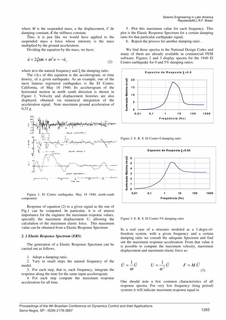
where ω is the natural frequency and ξ the damping ratio. The r.h.s of this equation is the accelerogram, or time
history, of a given earthquake. As an example, one of the most famous registered earthquakes is the El Centro, California, of May 18 1940. Its accelerogram of the horizontal motion in north south direction is shown in Figure 1. Velocity and displacement histories are also displayed, obtained via numerical integration of the acceleration signal. Note maximum ground acceleration of 0,32 g.
Figura 1: El Centro earthquake, May 18 1940, north-south
component
Response of equation (2) to a given signal as the one of
Fig.1 can be computed. In particular, it is of utmost importance for the engineer the maximum response values, specially the maximum displacement U, allowing the calculation of the maximum elastic force. This maximum value can be obtained from a Elastic Response Spectrum
2. 2 Elastic Response Spectrum (ERS) The generation of a Elastic Response Spectrum can be
carried out as follows. 1. Adopt a damping ratio. 2. Vary in small steps the natural frequency of the
model. 3. For each step, that is, each frequency, integrate the
response along the time for the same input accelerogram 4. For each step compute the maximum response
acceleration for all time.
5. Plot this maximum value for each frequency. This plot is the Elastic Response Spectrum for a certain damping ratio for that particular earthquake signal.
6. Repeat the process for another damping ratio . We find those spectra in the National Design Codes and
many of them are already available in commercial FEM software. Figures 2 and 3 display spectra for the 1940 El Centro earthquake for 0 and 5% damping ratios.
Figure 2: E. R. S. El Centro 0 damping ratio
Figure 3: E. R. S. El Centro 5% damping ratio
In a real case of a structure modeled as a 1-degre-of-freedom system, with a given frequency and a certain damping ratio we consult the adequate Spectrum and find out the maximum response acceleration. From that value it is possible to compute the maximum velocity, maximum displacement and maximum elastic force as:
UMFUUUU ===2
11
ωω (3)
One should note a few common characteristics of all response spectra. For very low frequency (long period) systems it will indicate maximum response equal to
E s p e c tro d e R e s p o s ta ξξξξ = 0 .0
0
5
1 0
1 5
2 0
0 ,0 1 0 ,1 1 1 0 1 0 0 1 0 0 0
F re q ü ê n c ia (H z )
Acele
ração
Máxim
a (
m/s
2)
Espectro de Resposta ξξξξ =0.05
0
1
2
3
4
5
6
0,01 0,1 1 10 100 1000
Freqüência (Hz )
Ac
ele
raç
ão
Má
xim
a (
m/s
2)
Proceedings of the 9th Brazilian Conference on Dynamics Control and their Applications Serra Negra, SP - ISSN 2178-3667 1265

3
maximum ground acceleration One such system has large masses and little stiffness. When the ground moves relatively fast the mass will not be able to follow it.As a consequence, the spring will displace the same amount as the ground. In the other hand high frequency (short period) systems have stiff spring and small mass. So when the ground moves the mass will be forced to follow in the same acceleration and the spring will not deform. We verify it by consulting the spectra
Exemple 1. Consider a water tower with total mass 10
ton at the top of a concrete column, fck=25 MPa, square section a=20 cm, height L=3m. Compute the maximum horizontal displacement excited by the 1940 El Centro earthquake. Adopt 5% damping ratio.
We will model this structure as a 1-degree-of-freedom system, namely the horizontal displacement.
The elastic modulus of the concrete, according to Brazilian Code NBR 6118/2003, is
MPafE ckc 280005600 ==
The moment of inertia of the square section is
444
103
4
12mx
aI
−==
The stiffness of a cantilever column is:
mNx
L
EIK /815,414814
135
10563 6
3===
The fundamental frequency of the structure is:
Hzfx
x
M
K025,1
10135
10564
62 ===ω
Consulting the Elastic Response Spectrum for 5% damping ratio we obtain the maximum
acceleration2/3 smU = and maximum displacement:
cmUU 23,71
2==
ω
The maximum shear force is 29,99 kN, leading to a maximum base bending moment 89,97 kNm. Base axial force is 98,10 kN.
2.3 Models with several degrees of freedom
Next we analyze models with several degrees of freedom, but always with lumped mass matrices, that is, diagonal matrices. This is the case of the usual shear-building model for tall buildings, and commercial FEM software.
Let us present the work sequence to perform the dynamic analysis of a n degree of freedom structure via Modal Superposition, excited by ground motion.
Step 1: Equations of motion
Write the equations of motion for the u physical coordinates:
su MpKuuCuM −==++ (4)
Step 2: Determine its frequencies and vibration modes.
Solve
[ ] 0uMK =−2ω
(5)
To obtain rω (r =1 to n) and the modal matrix ΦΦΦΦ .
Step 3: determine modal masses and modal loading
nrpmM iri
n
i
r
T
rr ,1/,2
1
=== =
φφφφφφφφφ M
ir
n
i
is
T
rr muP φ=
−==1
pφφφφ (6)
Proceedings of the 9th Brazilian Conference on Dynamics Control and their Applications Serra Negra, SP - ISSN 2178-3667 1266

Seismic Engineering in Latin America ReyolandoM.L.R.F. Brasil.
4
Step 4: write the uncoupled equations of motion for each mode
rrrrrrrr MPyyy /2 2 =++ ωωξ (7)
For seismic excitation:
=−=++
2
122
iri
n
i
iri
srrrrrr
m
m
uyyy
φ
φ
ωωξ
(8)
Step 5: modal response
Here we apply what we know about dynamic analysis of a 1-degree-of-freedom system. Each mode equation is solved via analytical or numerical methods. In the seismic excitation case, we can also use the Elastic Response Spectrum. The maximum displacement of each mode can be computed as a function of the maximum acceleration:
=
==n
i
iri
n
i
iri
r
r
r
m
m
UU
1
2
1
2
1
φ
φ
ω (9)
Step 6: determine the maximum response in the physical coordinates of the problem
As the maxima are not reached at the same time for all modes we use the square root of squares sum rule:
=
=k
r
rUU1
2 (10)
were k is the number of modes used in the solution. In many cases only the first mode is necessary.
Figure 4
1,5t
2,0t u3
u s
u1
x
y
u2
y
1,0t
3m
3m
3m
x
K
2K
ω3=46,10 ω2=31,05
1,00
-2,57
2,47
Modo 3
-0,676
-0,601
1,00
Modo 2
1,00
0,644
0,300
Modo 1
ω1=14,52
Proceedings of the 9th Brazilian Conference on Dynamics Control and their Applications Serra Negra, SP - ISSN 2178-3667 1267

5
Figure 5
Exemple 2.
Let us consider the model of Fig. 4, presented in [1], a 3 store building excited by seismic motion us = us(t). We adopt the shear building) model. Data: material elastic modulus E = 1,0GPa; upper column section 30 x 30cm.
The necessary matrices are
ton
=
0,200
05,10
000,1
M
mkN /
0,50,20
0,20,30,1
00,10,1
600
−
−−
−
=K
and the frequencies are
srad /
0995,46
0477,31
5217,14
=ω
Corresponding to the modal matrix:
−
−−=
47,2676,0300,0
57,2601,0644,0
000,1000,1000,1
ΦΦΦΦ
The columns of this matrix are the modes as displayed in Fig. 5
Next we present the necessary calculations for each mode
.
First mode
1º modo
ωωωω1 ωωωω1² f1 (Hz) Acel. Máx. C1 Umáx
14,5 210,25 2,307747 4,9214 1,423891 0,03333
mi uj1 mi * uji mi * uji² uj1 * Umáx
1 1 1 1 0,03333
1,5 0,644 0,966 0,622104 0,021464
2 0,3 0,6 0,18 0,009999
2,566 1,802104
Proceedings of the 9th Brazilian Conference on Dynamics Control and their Applications Serra Negra, SP - ISSN 2178-3667 1268
Seismic Engineering in Latin America ReyolandoM.L.R.F. Brasil.
6
Second Mode
2º modo
ωωωω2 ωωωω2² f2 (Hz) Acel. Máx. C2 Umáx
31,1 967,21 4,949719 4,8145 -0,510434 -0,002540
mi uj1 mi * uji mi * uji² uj1 * Umáx
1 1 1 1 -0,002540
1,5 -0,601 -0,9015 0,541802 0,001527
2 -0,676 -1,3520 0,913952 0,001717
-1,2535 2,455754
Third mode
3º modo
ωωωω3 ωωωω3² f3 (Hz) Acel. Máx. C3 Umáx
46,1 2125,21 7,337043 4,2593 0,090224 0,000181
mi uj1 mi * uji mi * uji² uj1 * Umáx
1 1 1 1 0,000181
1,5 -2,57 -3,855 9,90735 -0,000460
2 2,47 4,94 12,2018 0,000447
2,085 23,10915
Os deslocamentos máximos finais são:
u máx metros
u1 0,03343
u2 0,02152
u3 0,01016
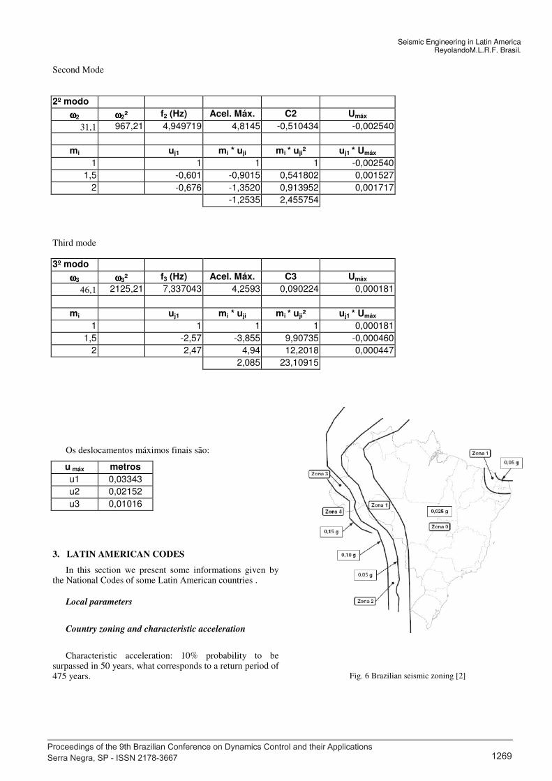
3. LATIN AMERICAN CODES
In this section we present some informations given by the National Codes of some Latin American countries .
Local parameters
Country zoning and characteristic acceleration
Characteristic acceleration: 10% probability to be surpassed in 50 years, what corresponds to a return period of 475 years.
Fig. 6 Brazilian seismic zoning [2]
Proceedings of the 9th Brazilian Conference on Dynamics Control and their Applications Serra Negra, SP - ISSN 2178-3667 1269

7
Fig. 7 Chilean seismic zoning [3]
Proceedings of the 9th Brazilian Conference on Dynamics Control and their Applications Serra Negra, SP - ISSN 2178-3667 1270

Seismic Engineering in Latin America ReyolandoM.L.R.F. Brasil.
8
Fig.9 Chilean seismic zoning [3]
Fig 10: Colombian Seismic zoning [4]
Fig. 11: Peruvian seismic zoning [5]
Proceedings of the 9th Brazilian Conference on Dynamics Control and their Applications Serra Negra, SP - ISSN 2178-3667 1271

9
According to the zone of the construction it is defined the design characteristic acceleration. In the Brazilian and Colombian Codes, these values are given directly by the zoning map. In some other codes, the values are given in tables. Exemples are the Peru[5] and Chile[3] codes.
e Chile
Local parameters
Soil classes
Another effect of the construction localization is the dynamic amplification due to the soil. To this purpose the soils are classified according to their stiffness related to the vibration period and a coefficient S for each class of soil. Exemples: Peruvian code [5]
and Colombian [4], for soils with decreasing stiffness.
Utilization Category (Construction importance)
The importance coefficient is a characteristic of the construction. In the Peruvian code [5] we have the U (utilization coefficient):
In the Colombian Code [4], for constructions of decreasing importance, from the essential ones as hospitals and firemen stations (group IV) to the normal ones (group I), we have importance coefficients called I.
Response reduction coeficients
Next, we take into account the capacity of the structure to dissipate energy and its stiffness. The largest it is the largest is the response reduction coefficient R, a relation between
Proceedings of the 9th Brazilian Conference on Dynamics Control and their Applications Serra Negra, SP - ISSN 2178-3667 1272

Seismic Engineering in Latin America ReyolandoM.L.R.F. Brasil.
10
the elastic and plastic behavior of the structure. It is very large the number of such coefficients in the several Codes. For exemple, lets take the Peruvian Code[5]:
4. DESIGN ELASTIC RESPONSE SPECTRA
Brazil[2]
Peru[5]
onde
Colômbia [4]
5. SEISMIC ANALYSIS VIA THE EQUIVALENT HORIZONTAL FORCES METHOD
Peru [5]
Shear force at the base of the structure:
where
The fundamental period of the structure may be estimated as
Horizontal forces distribution along the height
gR
ZUSCSa =
5,25,2 ≤
= C
T
TC
p
PR
ZUSCV =
5,25,2 ≤
= C
T
TC
p 1,0≥R
C
T
n
C
hT =
60,45,35=TC
V
hP
hPF
n
j
jj
iii
=
=
1
Proceedings of the 9th Brazilian Conference on Dynamics Control and their Applications Serra Negra, SP - ISSN 2178-3667 1273

11
6. CONCLUSION
In this lecture we resumed some elements of practical seismic analysis of structures as prescribed by some construction codes of Latin American countries.
ACKNOWLEDGMENTS
The author acknowledges financial help by CNPq, a Brazilian research funding agency.
REFERENCES
[1] R.W. Clough, J. Penzien, Dynamiccs of Structures, Mc Graw Hill, New York, 1994..
[2] ABNT, Projeto de estruturas resistentes a sismo-Procedimento, projeto 02:122:15-001:2006, Rio de Janeiro, 2006.
[3] Norma Chilena Oficial - Diseño sísmico de estruturas e instalaciones industriales, NCh2369.Of2003, Santiago, 2003.
[4] AIS – Normas Colombianas de Diseño y Construccion Sismo Resistente, NSR-98, Bogotá, 1998.
[5] National Building Code, Technical Standard of Building, E.030, Earthquake resistant design, Lima, 2003
Proceedings of the 9th Brazilian Conference on Dynamics Control and their Applications Serra Negra, SP - ISSN 2178-3667 1274