dynamics of ocean structures prof. dr. srinivasan...
TRANSCRIPT

Dynamics of Ocean Structures Prof. Dr. Srinivasan Chandrasekaran
Department of Ocean Engineering Indian Institute of Technology, Madras
Module - 1 Lecture - 7
Wave Forces, Current
(Refer Slide Time: 00:20)
We will have the seventh lecture on dynamics of ocean structures. Let us quickly see
what we have discussed in the last lecture. We discussed about different types of
offshore structures. We also discussed about different types of coastal structures. We
also discussed about the structural action of these kinds of structures under the given
environmental loads. We very briefly discussed about the dynamic characteristics, which
are important of these kinds of structures. For example, the mass of the structural system
may be a matrix, it may be single value, the stiffness then the damping, which can arise
from material as well as from the hydrodynamic loading, etcetera.
Then in the last lecture we discussed about different kinds of forces. We started with the
wind force and we said that if we want to estimate wind force or the effect of wind force
on a given structural system, the system should behave in a cylinder manner. That is the
height of the structural system or the member with respect to the least lateral dimension

of the structure should exceed 5. So, the dynamic action will be invoked in the structural
system. Therefore, we must do dynamic analysis.
(Refer Slide Time: 01:50)
Now, essentially dynamic analysis need not be done, even though the force may be a
function of time. Even though F can be a function of time, still you may not do a
dynamic analysis, you can do a quasi static analysis or simply a statistical response. It is
important that the structural system, where the load is applied should also invoke the
dynamic characteristic in the behavior. So, we discussed about the wind force. Today, we
will talk about wave forces. We will talk about forces from current. We will talk about
forces from earthquake loads. We talk about forces from marine growth, etcetera. Of
course, ice loads.
So, all these comprise, including the wind force, as what we call the environmental
loads, which act on the offshore structure. So, interestingly we have understood that,
even though the force can be a function of time, depending upon the structural system
characteristic, you may do dynamic analysis or you may not do a dynamic analysis. That
was the brief summary what we had till the last lecture. In the present lecture, we will
talk about now the wave forces.

(Refer Slide Time: 03:21)
Wave forces on offshore structures or wave loading on offshore structure is one of the
most important of all the environmental loads. Determining these forces require the
solution of two separate, but interrelated problems. Let see what are they. The first stage
is computation of sea state.
(Refer Slide Time: 03:45)
So, wave force estimate has got two important stages. One, you must identify the sea
state. The stage is to identify the sea state. You must use a specific profile of the sea state
or you must use a specific theory to simulate the sea state and based on that, you must
derive the water particle kinematics. The moment I say water particle kinematics, I am
interested in knowing the horizontal water particle velocity, the vertical water particle
velocity, the horizontal water particle acceleration, the vertical water particle
acceleration.
Once I know this, I must then be able to estimate the forces on the member. The second
stage is to estimate the wave forces on individual members and then on the total
structure. So, it has got two components. I want to know their forces on individual
member and subsequently, I also want to know the total force on the entire structure. So,
if you identically compare this with the same algorithm what we had in the wind force,
there also we first estimated the velocity. From the wind velocity, we estimated the
pressure acting at a specific point; found out the coefficients responses for the terrain
quantifications etcetera; estimated the force at every specific point and based on that, we
either found out the effect of the forces moment on the member or the force acting on the
member as such, if I know the projected area of the member. Similarly, here the same
algorithm, I will talk about the water particle kinematics first and then I will talk about
the force estimation on these members. So, there are two approaches to quantify the sea
state, which are very important level of estimating the wave forces.
(Refer Slide Time: 05:56)
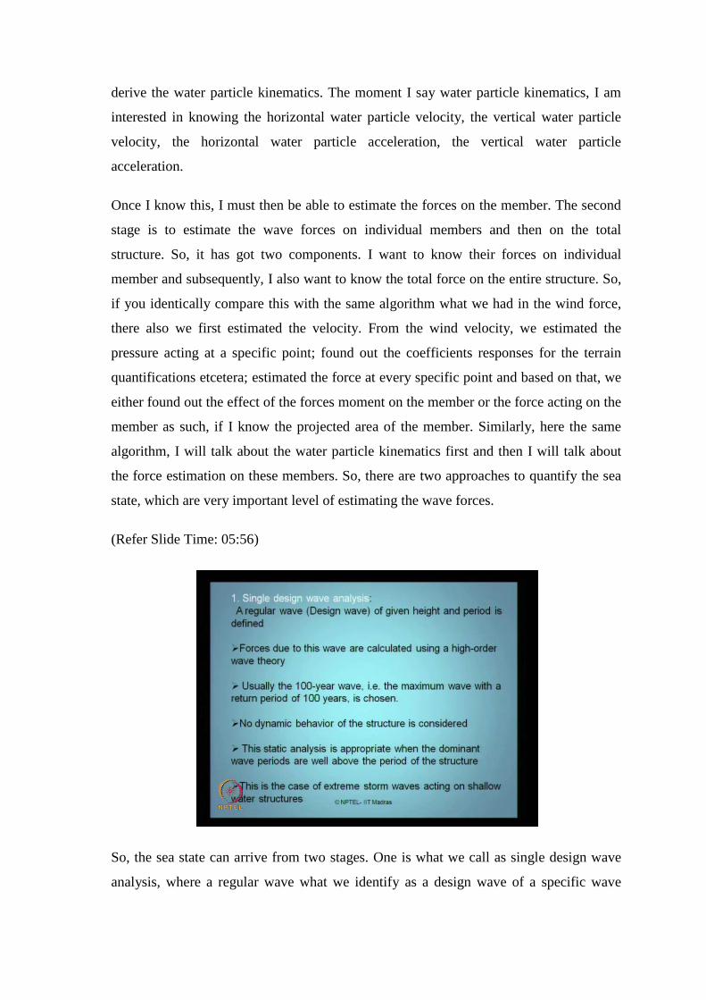
So, the sea state can arrive from two stages. One is what we call as single design wave
analysis, where a regular wave what we identify as a design wave of a specific wave

height and the wave period is defined. So, you define a specific wave, whose wave
height and wave period are given to you. Forces due to this wave will be calculated using
higher order wave theory. You will use a higher wave theory and estimate the forces
based on this given wave height and wave period. That is, for the given sea state,
estimate the forces using higher order wave theory. Usually, we consider 100 year wave,
that is, a maximum wave with return period of 100 years. So, that could be your design
wave or single design wave, which we will consider for the analysis.
Now, when you do that kind of analysis, where you are talking for the maximum wave
within a span of 100 years, then dynamic response is not considered. You do not look at
the dynamic behavior of the structure, whereas in wind, you are talking about the
dynamic behavioral structure. But in this case, since you are estimating a single design
wave whose wave height and wave period was considered to be the maximum in the past
100 years, do not look for the dynamic behavior.
So, this becomes a static analysis and it is appropriately equivalent to the dominant wave
period for all period of the structure and the structure will be designed, so that, the period
of the structure will be well above or well below depending upon what kind of structure
is that, depending upon the wave period. So, this is the case of extreme strong wave
acting on a shallow water structure. This is one approach what people have to qualify the
given sea state based on which you will estimate the water particle kinematics. The
second approach what people have in the literature is random wave analysis.

(Refer Slide Time: 07:40)
So, here what they do is, they talk about the statistical analysis on the base of wave
scattered diagram and the wave scattered diagram is obtained for a specific sea state,
where the platform will be installed. So, what we call, location specific wave scattered
diagram. You pick up this diagram and do a statistical analysis on the data from the wave
scattered diagram.
So, you pick up an approximate wave spectra to define the performance of the analysis in
frequency domain. Then appropriate wave spectra is used to generate what we call
random waves, if we are looking for dynamic analysis of extreme wave loading in deep
water structures, which is one of the important criteria. So, it is very essential that we
look for a random wave analysis. Then you have to do a dynamic analysis when you are
talking about compliant structures. Why I say as compliant because the moment I go to
deep water structures, my structure will have relative motion with respect to the water
particle or visible to the wave which is approaching the structure.
So, with statistical methods, most probable wave force, maximum, occurring at that life
time will be calculated. Now, it is very interesting that to calculate the maximum wave
force, which is going to happen in the given life time of the structure, you use a linear
wave theory. Now, there is a diversion here. Either use a linear wave theory to estimate
the water particle kinematics or you can use higher order wave theories also. We will
quickly see what are these theories. Very quickly because we are not going to focus on

how to estimate the force and the structure. My worry is how to do a dynamic analysis,
provided if f of t is known to me. If I know the forcing function, then I must know how
to do a dynamic analysis. But to understand how to estimate forces, we must have an
idea that where are we facing the source to obtain the forces. As I just now said, when
we talk about either single design wave or a random wave analysis, in both the cases, it is
interesting that I must identify what I call a sea surface elevation, which we discussed in
the last lecture as well. We just call it as eta. So, I must design or I must define the sea
surface elevation eta, based on which, I will then compute the water particle
accelerations in velocities, both in horizontal and vertical. Of course, this is horizontal
and this is vertical.
(Refer Slide Time: 10:23)
So, there are some assumptions based on these theories. Wave theories describe the wave
kinematics, that is, water particle velocity in acceleration on the basis of potential theory.
Waves are assumed to be long crested waves. They can be described a two dimensional
flow and characterized by the following parameters; wave height, wave period, water
depth, which is small d, capital D denotes the dimension or the diameter of the member,
wave number, circular frequency omega and cyclic frequency f. So, these are some of the
parameters, based on which I characterize the sea surface elevation or my sea state.

(Refer Slide Time: 11:02)
Once I know this, I have got different common theories which we all aware when talk
about wave hydro dynamic course; linear airy theory, Stokes fifth order, solitary wave
theory, Cnoidal theory, Dean’s stream function theory and numerical theory by
Chappelear. So, we are not going to discuss all these theories. But for understanding, I
will just quickly discuss linear wave theory and Stokes fifth order theory. Very briefly
give you some tutorial, so to make you to understand how to estimate wave forces on the
members based these on theories. So, the wave parameters are given here. Water depth is
small d, wave height is capital H and we know what is a crest and what is trough and we
also talk about wave celerity in meter per second.
(Refer Slide Time: 11:46)
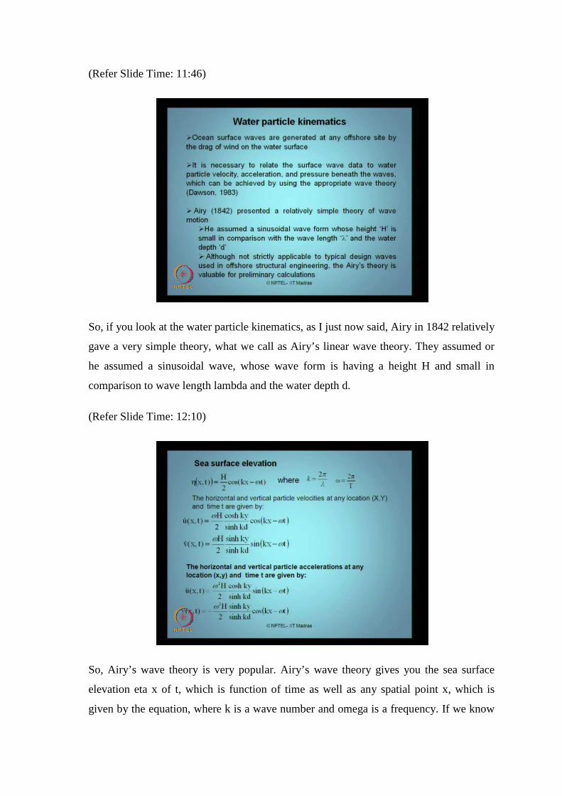
So, if you look at the water particle kinematics, as I just now said, Airy in 1842 relatively
gave a very simple theory, what we call as Airy’s linear wave theory. They assumed or
he assumed a sinusoidal wave, whose wave form is having a height H and small in
comparison to wave length lambda and the water depth d.
(Refer Slide Time: 12:10)
So, Airy’s wave theory is very popular. Airy’s wave theory gives you the sea surface
elevation eta x of t, which is function of time as well as any spatial point x, which is
given by the equation, where k is a wave number and omega is a frequency. If we know

eta x of t, from this you can easily estimate u dot and v dot, which are horizontal water
particle velocity and vertical water particle velocity available in the literature. You need
not have to copy this. These are all standard literature. Any hydrodynamics text book
will help you to estimate what are these equations. You may not have to worry about the
equations of this. Once I know, I can differentiate this and get the accelerations also. So,
I have got u double dot and v double dot n.
Now here, the only important thing is, what we must realize is, it is a function of x,
which is spatial point. So, function of t, which is the time as well as function of y, which
is a dimension measured along the water depth. So, it is a three dimensional function. A
time is a variant, x and y are the points of your interest, where you want to. I can give a
very quick example how this can be estimated.
(Refer Slide Time: 13:28)
For example, let me say I have a cylinder. I have a cylindrical member, a single member.
The cylindrical member is hypothetically fixed to the sea floor. This is my mean sea
level and of course, I will indicate this as my water depth d. This member may be hollow
having some thickness t, but I am bothered about the outer diameter, which is d and the
wave is specified with a specific height and the specific wave length etcetera. So, if I
take anywhere as my origin, let say for example, I take this outer end as my origin. So, I
will define x comma y based on the point here and let t can be any instantaneous value 0

or may be 0.1 seconds, any value you want. So, you can find the variation of the force at
any given time t, for any specific point x and y.
For example, I want to know the force here. So, I must know the value of y, which I call
as y 1. I must know the value of x, which will remain as 0 because this is the origin on
the same line and again pick up any t of any instant or you can get a time history of the
velocity and acceleration variation on this point on the cylinder using this theory. So, I
will able to estimate F 1 F 2 F 3 F n etcetera, at any point of x y at any time t, using this
eta x of t u dot u double dot v dot and v double dot. Is that clear, right?
(Refer Slide Time: 15:17)
So, there are hitch backs with this theory. Velocity potential described by this does not
satisfy the Laplace equation, but it satisfies the dynamic free surface boundary condition.
Therefore, in many physical situations, linear theory, even by stretching modifications,
there are many modifications given by this theory by Hogben, Wheeler and Chakravarti.
These three researchers subsequently modified linear theory, Airy’s theory.

(Refer Slide Time: 15:50)
Hogben, Wheeler and Chakravarti, three individual researchers at different times
modified this theory. These modifications are addressed in the literature as stretching
modifications. We should agree that Airy’s theory speaks about the force only till the m s
r. It has talk about how to estimate the forces beyond the m s r. So, Hogben and Wheeler
stretched this above till H by 2 as well. So, what we call as stretching modification. So,
they have modified the eta surface elevation given by Airy’s and of course, they have
given suggestions for u, u double dot and v dot and v double dot. So, there is a small
modification, which you will get in terms of its force estimate, when you use Airy’s
theory or when you use stretching modification. But the difficulty in the literature is,
even after the stretching modification, it is found that the theory is not adequate to
describe the water particle kinematics completely. So, then why Airy’s theory is being
used? It is good for estimating preliminary values of the forces on the member. Then
what was the solution? Solution said, people, you should move on to higher order wave
theories.

(Refer Slide Time: 17:13)
One such higher order wave theory is given by Stokes. Lord Stokes gave it in 1880,
which is called third order; subsequently fifth order wave theory. So, Stokes theory
expanded the wave in a series form and determines the coefficients of individual terms to
satisfy the appropriate hydrodynamic behavior for finite amplitude waves. Then the
extension on this theory was suggested in 1960 by Skjelbreia and Hendrickson, which is
available in the literature. Now, there is a problem here. Because of the slowness of
convergence in the series for shallow water, these theories considered to be valid only in
the regime, where d by lambda; lambda is a wave length should be greater than 0.1. So,
you must check that your d is the water depth and lambda is the wave length for a given
wave. If this function is greater than 0.1, this theory will work better. So, if we look at
how Stokes fifth order deviated Airy’s theory quickly in terms of water particle
kinematics, I will come to that slide here.

(Refer Slide Time: 18:16)
The e tags of p, using Stokes fifth order theory, why it is fifth order because you will see
that the series here starts from 1 to 5. So, I am adding 5 terms in the series. That is why
this theory is called fifth order wave theory. So, it is nothing but summation of this,
where you have constants F n F 1 F 2 F 3 F 4 and F 5, because n runs from 1 to 5. All
these values are available in the literature. You can refer Dawson 1983 and H Patel 1989
to have all these coefficients. Also, my own paper on ocean engineering journal also
gives you all these coefficients in single shot. The references are only available in the
website of NPTEL under this course. So, you can look at Dawson’s paper or book or you
can look at Patel’s book. All these, both the books as well as papers will give you
coefficients of all these values in detail. So, what we are interested here is not to discuss
those coefficients.

(Refer Slide Time: 19:19)
Once I get my sea surface elevation in x of t, then I can find again u dot and v dot, again
as a series of 5 terms, n sums from 1 to 5. Similarly, accelerations again summed up
from 1 to 5, where R n’s, S n’s n etcetera G n’s are all available as constants given in the
literature. I am not talking about them here, whereas, c s in this equation is the wave
speed, which is given by an expression as you see here, where again the constants c 1 c 2
etcetera are there. So therefore, Stokes fifth order wave theory is essentially an empirical
base device relationship, which is applicable for deep waters, where d y lambda is more
than 0.1.
So, we quickly saw two theories. One is a simple simplified linear theory, which can be
applied to estimate the water particle kinematics and the corresponding accelerations and
velocities. Subsequently, you can also use high order wave theory to estimate again u dot
v dot u double dot v double dot, if you are interested in going for more accuracy in the
calculations. So, with the example of these two theories, we already know how to
estimate the first concept in the wave force, which is defining the sea state and
estimating the kinematics.

(Refer Slide Time: 20:40)
Coming back to how to estimate the forces in the member or in the structure, we study
quickly about wave structure interaction, structures which are exposed to waves
experience substantial forces, which will be subsequently higher than that of the wind
loading. It has been seen in the literature that we compare the magnitude of forces caused
by wind against waves, wave action is more severe than wind action on structures, right.
So, forces result from dynamic pressure variation and the water particle motion, two
different cases are available in the literature, which are distinctly different. One is large
volume body and other is slender hydro dynamically transparent body.
If we talk about large volume body, then they are called hydrodynamic compact
structures. The influence of wave field on the structure will be by diffraction and
reflection. When the wave hits the structure to diffract as well as part of the wave
particles will reflect from the body. Forces on these bodies have to be determined by
numerical calculation, based on what we call diffraction theory. If you talk about slender
hydro dynamic transparent bodies, they have no significant influence on the wave field,
because they are transparent to hydrodynamic wave field. Forces to be calculated in a
straight forward manner given by Morison equation. Morison equation has only one
limitation. The D by L value should lie within a limit of 0.2, where d, the diameter of the
member, it is a capital D here, where L of course, is the wave length.

So, if a member satisfies this criterion, whether diameter by the wave length is within
0.2, I can use Morison equation to estimate the forces. So, I am moving to the second
part here. The first part said how to identify the sea state. We have discussed two
theories. Simple linear Airy’s wave theory given by stretching modifications. There are
some limitations in this theory. People never accepted this theory for higher order perfect
calculations. But for preliminary values, this theory is still valid. People went further
down the step and saying, I am going to use higher order theories. Stokes fifth order
theory is recommended. So, using both the theories, I can estimate the kinematics of
water particle in horizontal and vertical axis.
Once I know this, I can quick up a member, which is hydro dynamically transparent and
I can find out the wave forces on the member. You may be worried that, why we are not
talking about large volume bodies in the course. As I said, if it is a gravity based
structure, it can be a large volume body, where we estimate forces based on diffraction
theory. But mostly, all our structures, which are ocean structures on offshore platforms,
are slender in nature. So, they are hydro dynamically transparent systems. We will talk
about using Morison equation in these kinds of systems.
(Refer Slide Time: 23:20)
So, for example, look at steel jacket structure. They are hydro dynamically transparent.
So, the steel jacket structure has the members fixed at the bottom. So, there is no relative
movement of the structural member with respect to that of the waves. So, it is fixed at the

bottom. Therefore, I can easily find out the forces from this expression, where f is the
wave force per unit length on the cylinder, whereas u u dot, I mean, u dot, u double dot,
C d C m are all standard functions, which are available in the literature. Where one is
called drag coefficient C d and other is called inertia coefficient C m. rho of course,
density of sea water, D, capital D is a diameter of the member and of course, u dot and u
double dots are velocities and accelerations in horizontal axis of the member. So, you
can easily find out the force, if it is fixed like in case of steel jackets structures.
(Refer Slide Time: 24:16)
In case of compliant structures, for example, like TLP’s, we already know compliance
stands for the word movement is a relative motion. Therefore, the structure also moves
either in the wave direction or the direction opposite to the wave propagation. So, x dot
here is a structural velocity. So, I will try to find out the relative motion between the
structure or the member and the wave, therefore the velocity terms are modified as u dot
minus x dot. And there is a product here, u dot minus x dot and there is an absolute value
of u dot minus x dot. There are two reasons why this term, which is drag associated term
is important. This force has got two terms. One is called the drag term, because C d term
is appearing there. C d stands for drag coefficient. Other term is C m is called inertia
coefficient or inertia force.
So, if you look at the drag term, there is a product of u dot minus x dot multiply by u dot
minus x absolute value. This product makes the drag term non-linear. That is why we

call non-linear drag. This term makes the drag term non-linear number one. Number two,
the absolute sign of u dot minus x dot preserves the direction of the force.
For example, if I do not have this absolute value, you will see this product, if x dot is
more than u dot or x dot is an opposite direction of u dot, the multiply will make it
always positive. But then I will not be able to prevent or let say preserve the
directionality of the force. So, I am putting absolute value in one of them, so that, the
directionality of the force is also protected in the calculation. So, this term is very
important for us because of two aspects. This introduces non-linearity in the force. Two,
this gives me a relative understanding of, in what direction net forces apply. Is it in
positive x or negative x? Is that clear?
So, I can easily estimate the force in the member, at any point I want on a given member,
because to estimate the force, I need two things. I want the velocity horizontal or vertical
and I also want the acceleration horizontal or vertical because you see, here in this force
term, two things are required. One is u dot and other u double dot also. I want both,
velocity and acceleration.
So, I qualify this from specific theory, may be Airy’s theory or may be Stoke‘s fifth
order theory. Once I get this, I find the force in a member at any point of my interest as F
1 F 2 F 3 etcetera. I can sum them up all to get the member force in the entire structure,
as I did for wind forces also. So, this is how I estimate the forces in the member
counteracted, because of wave actions. Any doubt? Any difficulty here? This is one of
the important environmental loading, which will come on the offshore structure. There is
a tutorial based on this at the end of this lecture. I will give you that. So, you should be
able to solve them.
So, anyway, in this lecture, we are not focusing or the course itself, we are not focusing
on how to estimate these forces in detail. But when I move on to the second module on
this lecture, I will show you some examples using coding, how the forces have been
estimated. I can even pass on the mat lab coding to you. You can work out the forces
yourself. But I will not be able to solve the problem explaining you how to work out
force on every point of y 1 y 2 y 3. That is not required. You can do the exercise at your
own level. Yeah, that is interesting part. I will come to that, when I have to do what we
call modify Morison equation. That will come as an added mass term. It is a very

interesting question. Why we are not considering the relative acceleration? That is fine.
That is called added mass term. We will talk about, because I am talking about the added
mass term because m x double dot will be the inertia force exerted by the structure. m x
double dot will be the inertia force exerted by the structure. I will handle the term
separately in my analysis. It is there. It is very much valid. It is there, but I will handle it
separately.
(Refer Slide Time: 28:27)
I think, I can skip this because most of this is important only in theoretical point of view.
We have already said Morison’s equation force is non-linear etcetera.

(Refer Slide Time: 28:36)
In addition, we have got also called lift force and slamming forces, F L and F S, whereas,
C L and C S are called lift and slamming coefficients. The lift force is generally
perpendicular to the member axis and it is related to the vortex shedding frequency,
whereas, slamming force acts on the underside of horizontal member near the mean
water level and are impulsive and more or less vertical. Not necessarily vertical, nearly
vertical. So, that is about the lift forces and slamming forces. So, we talked about the
wave forces. Wave force on horizontal vertical direction from the water body plus lift
and slamming forces as well, if you know the equations here.
(Refer Slide Time: 29:28)
We will talk about buoyant force. We already know when the body is partially
submerged, because of the displaced volume of the body, I get a buoyancy force. We all
understand this buoyant force. It is very simple to compute. A buoyant force acting
around the structure, it acts at a point which is called centra buoyancy for a given whole
structure or a single cylinder, depends upon the submerged volume or the displaced
volume of the member in water.
(Refer Slide Time: 29:43)
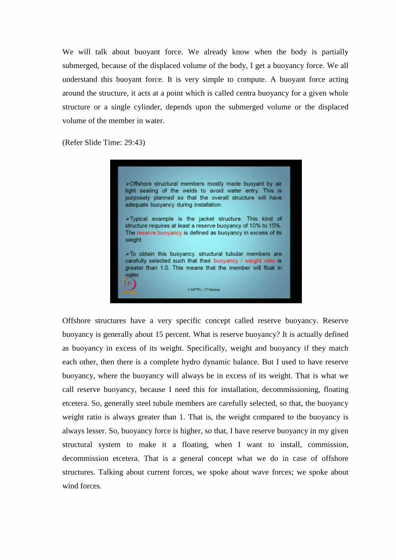
Offshore structures have a very specific concept called reserve buoyancy. Reserve
buoyancy is generally about 15 percent. What is reserve buoyancy? It is actually defined
as buoyancy in excess of its weight. Specifically, weight and buoyancy if they match
each other, then there is a complete hydro dynamic balance. But I used to have reserve
buoyancy, where the buoyancy will always be in excess of its weight. That is what we
call reserve buoyancy, because I need this for installation, decommissioning, floating
etcetera. So, generally steel tubule members are carefully selected, so that, the buoyancy
weight ratio is always greater than 1. That is, the weight compared to the buoyancy is
always lesser. So, buoyancy force is higher, so that, I have reserve buoyancy in my given
structural system to make it a floating, when I want to install, commission,
decommission etcetera. That is a general concept what we do in case of offshore
structures. Talking about current forces, we spoke about wave forces; we spoke about
wind forces.

(Refer Slide Time: 31:02)
We also saw slamming and lift forces. We did talk about the current forces, the tidal,
circulation and storm generated currents exert additional forces on the member. When
insufficient field measurements are available, then current velocities may be directly
taken from international course. One example is, appendix A of DNV code. In offshore
platform design, general effects of current are superimposed on waves. That is a very
important concept.
(Refer Slide Time: 31:29)

What I do here is, if we look at the Morison equation force, let say half rho C d dia u dot
minus x dot plus u dot of c. I will just superimpose the current on the water body velocity
itself. That is why I modify this. So, in offshore structures, this is only a drag component.
Similarly, we have the inertia component also. So, I superimpose the current velocity
directly on waves and find out additional force. I add them vectorially. That is how I will
take the influence of current on my structural system.
(Refer Slide Time: 32:09)
Look at the additional forces acting on the structure, one important additional force
coming on the structure in offshore structure is earthquake load. Offshore structures in
seismic regions are typically designed for two levels of earthquakes. One is called
strength level and other is called ductility level. For strength level earthquakes, they are
defined as reasonably likelihood of not being exceeded during the platform life. The
mean recurrence interval of these earthquakes is about 500 years. The structure is
expected to design elastically for this kind of force.
For ductility level earthquakes, is defined as close to the maximum credible earthquake.
What m c e in the analysis, the structure is designed for inelastic response and have
adequate reserve strength to avoid collapse. It means, one methodology of estimating
earthquake force talks about elastic response, which is nothing but the strength level. The
other method talks about the inelastic response, which talks about the ductility level and I
think we can quickly understand, if we look at the stress stain curve.

(Refer Slide Time: 33:23)
The stress strain curve of steel, which is one of the favorite materials for construction of
offshore structures is a strain axis. This is stress axis is a typically stress strain curve of
steel, which is being used for offshore construction purposes. Look at my strain value at
ultimate. To strain value at yield, I call this strain at yield value. The strain at ultimate.
The strain at ultimate; the strain at yield is what we call ductility ratio. For steel, can be
as high as 6.
So, steel has got an enormous capacity of strain at ultimate, compared to strain at yield, 6
times. So, this area is very large. So, one can look for Ducticle level design also in
earthquake loading for offshore structures. This is what we use in case of plastic design
of structures. We are not going to talk about in detail now. So, we are interested in how
to estimate the forces, not the design.
Now I wonder, that when we talk about analysis, why we are talking about design? Is
there any relationship between analysis and design? First of all, what is analysis and
what is design. Quickly. What is analysis and what is design? I mean, it is a very
fundamental question. That is, in case of analysis or design? So, when you talk about
analysis, as you said, analysis is a part which explains me how to estimate forces coming
on the structural system. Not only the forces, but also the responses. For example, what
is a deflection, what is a bending moment? All these are analysis; what is the stress level,
what are stain level. Then what is design?

Based on these calculated values for a given force, based on the given response of a
structural system, based on the material characteristic of the member, we also find out
the cross section dimensions of the member. Now interestingly, if we do not know the
cross section dimension of the member, you cannot do the analysis. Because, to find
stress, you need area. To find area, you note the diameter. Now, diameter obtaining is a
design part. So, analysis and design are inherently coupled to each other. You cannot
separate them. Is that clear?
So, what we generally do is, we preliminarily assume a dimension of the member; do the
analysis; always check the analysis and design for the safety of the member. So, analysis
and design are together. We cannot separate them because if you do not know the design
concepts or design criteria of the member, you cannot analyze it at all. So, that is why in
case of design and analysis. In case of dynamic analysis, we talk about design also
partly, but anyway the ductility level and strength level are leading forward to a plastic
design of structures like this. So, we will not talk about that in this course. But still there
is a clue that this will help us to talk about plastic design of structures in case of offshore
structural systems.
(Refer Slide Time: 36:48)
Look at the Ice and snow loads. It is very simple. Ice is the primary problem in arctic
region, because ice of huge blocks can come and hit the structure. They can cause impact
loads. So, the impact loads caused by large block of ice, can be easily obtained from an

equation F i C i f c n A, where a is exposed area of the structure, whereas f c is a
compressive strength of ice and C i is the coefficient accounting for shape, rate of load
application and other factors. Generally, the value lies between 0.3 to 0.7. So, I can find
out force at any point i, which is f i caused because of impact load coming from the ice
formation on a given offshore platform.
So, this can be statistically estimated as a horizontal ice force, F i from the simple
expression, which is very much valid in case of arctic regions. So, it is very interesting
for us to know that, ice can approach the platforms at a very velocity equal to about 1
meter per second also. It has very high velocity, right. It can come and hit the structure.
Therefore, ice loads are substantially high. So, we must account for them.
(Refer Slide Time: 38:04)
Interestingly, there can be loads caused because of delta t, that is temperature or thermal
variation. As we understand along the depth of an offshore structural system or in a sea,
there is a tremendous variation of temperature. This will influence, because the member
is common. The member is running from the m s l till the depth of the structure r of
ocean. But the temperature here and temperature here are different. So, the member can
be subjected to additional loads passed by this thermal variation. So, they are ultimately
given for a specific data available in North Sea in BS6235 for example. One can
calculate the additional stresses caused by this thermal variation on the members.

(Refer Slide Time: 38:47)
Interestingly, marine growth is a very important problem as far as offshore structure is
concerned. Marine growth is nothing but accumulation of biological organism around the
surface of the member. To increase the diameter of the member, there are very severe
problems related to marine growth. The diameter of the member is increased. So, marine
growth has problems.
(Refer Slide Time: 39:15)
It increases the diameter of the member, because around the member, there can be
substantial growth of marine. So, the diameter of the member is now increased, D mu.

So, diameter has gone high. The moment the diameter goes high, force due to Morison
equation goes high because force is a function of dia, half rho C D dia. There is a
function of diameter here.
The diameter increases, force will increase. That is first problem. Second problem, as the
diameter goes high, it adds the mass to the structure and my inertia forces will increase.
The third problem with marine growth, it also changes C D and C M values, which are
the coefficients used in equation because if the surface becomes smooth, C D is different.
The surface becomes rough, C D is different. Here, the roughness on the surface
increases, the C D. We have just now saw C D. If C D is increased, force on the member
automatically increases.
The fourth problem, it will not allow the structure to be inspected. You cannot inspect
the region of the structural system for any failure because marine growth will cover the
structure; cannot inspect it. So, these are couple of very serious problems associated in
terms of its maintenance as well as in terms of its design and analysis, as far as marine
growth is concerned. How it is actually done? It is done by equating the compensation in
terms of increasing the thickness of the member, the design itself. That is how it is
compensated in the design. The marine growth can increase the diameter up to about 0.3
meters also. It can be 300 mm. So, as thick as that.
(Refer Slide Time: 41:23)

There can be also additional loads because of tides. Tide affects the wave and current
loads very seriously, through the variation of the level in the sea surface. Tides can be of
two types, astronomical and storm surges. Astronomical tides caused essentially from the
gravitation pull of moon, whereas, storm surges are caused by combined action of wind
and barometric pressure. The combination of these two is what we called storm tide.
(Refer Slide Time: 41:52)
Now interestingly, this leaves, storm surges can be as high as 3 meters even. It is very
high. Astronomical tides depend on the geographical location and the phase value of the
moon actually.

(Refer Slide Time: 42:06)
So, this is a very interesting part. Depending upon the storm surge and astronomical
tides, the mean water level, the mean water level as you see here, gets redefined. So,
what is the problem when this mean water level gets redefined to still water level R to
HAT, that is high astronomical tide. The problem is, as this mean water level, which is to
be considered in the analysis, goes higher, the immersed volume of the cylinder gets
increased. The immersed volume changes buoyancy of the material or the member. The
buoyancy force is increased. When the buoyancy force increases structures like TLP
SPA, where they are moved to the sea bed, then the force on the teeth was gets changed.
It means, astronomical and storm surges include additional forces on the members like
this.
So, actually they redefine the mean water level. Just now, we saw Airy’s theory cannot
be applied, if you want to extend this or stress this beyond the mean water level. Of
course, there are stretching modifications suggested by different researchers. But still, it
is not accurate. So, the mean water level added to storm surge and astronomical tide
ranges will vary and will alter the force on the members indirectly by improving the
submerged volume of the member.

(Refer Slide Time: 43:39)
So, that is the effect of tidal forces on the members. Interestingly, sea floor movement
can also happen. That also causes displaced type of forces on the member. This is very
serious when you talk about fixed platforms or gravity based structures. Now, why this is
not important for floating structures or structures which are compliant in nature?
Because, the structure of compliant in nature does not rest on the sea bed. They are only
anchored to the sea bed. Therefore, influence of sea floor movements on this kind of
structures will be less influential. It will be very less, whereas in jacket structures,
whereas in the case of a pile supported or pile rested structures, they will be severe.
(Refer Slide Time: 44:15)

So, these are the different kinds of forces what we saw. In the next lecture, we will talk
about the characterization in dynamic analysis. We will move to single degree of
freedoms. I have got tutorial sheets for you. So, quickly copy down these questions and
these are self-answered. You should be able to answer them on your own. How will you
estimate wind force on offshore deck? Discuss briefly different analytical concepts
available for estimating wave forces on offshore structures. Draw a neat sketch to
explain different wave parameters considered to estimate the wave forces on members.
Explain briefly what you understand by wave structure interaction. How can you
estimate the maximum force on a given offshore structure?
What you understand by a maximum force on a given offshore structure? You have got a
member, may be fixed or compliant. The direction of movement of the member may not
be in the same alignment as that of the wave. Wave may not approach the member
always at the access of the member. It can be even directional also. Therefore, the
component, the phase component phi plays a very important role and we know, the sin
and cosine components, which are u dot and v dot on a given member may not occur
simultaneously. They are out of phase by 90 degrees. So, at a given point of time, one
must have an idea, what is a maximum wave force coming on the member. Is that clear?
How will you estimate that? That is what I want to know from you.
There is a empirical equation given for this. It is available in one of my books, which I
wrote, which I gave you as a reference; myself and Bhattacharyya. So, look at that book.
We have an equation. It is a closed form for estimating the maximum wave force on the
member. What do you understand by the buoyancy force? How will you estimate it?
Why current forces are important in offshore structures? Write a brief note on earthquake
forces, snow or ice loads and accidental loads which are caused on offshore structures.
What is significance of marine growth and how it is important for dynamic analysis in
offshore structures?
So, the clue here is, as far as the diameter is increased, force increases; in my dynamic
analysis, f of t enhances. The diameter increases, mass increases. In dynamic analysis,
inertia component of the force increases. So, it is important for me, why marine growth
is necessary to be accounted in the dynamic analysis of offshore structures. That is the
first tutorial in this lecture, which you like to answer for self-assessment.

(Refer Slide Time: 46:54)
The second tutorial will be on problems. So, I have a pile diameter D. What I will do is, I
will take a print out of this and pass on to all of you. So, you need not have to write
them. You can try it to solve them. Remember very clearly, none of the questions in the
examination will be based on this. Do not try to think that you will answer them and try
to bring it here; copy it. Not going to help you at all. I will not ask you even a single
question what I have given in the tutorial at all to you. I will ask questions based on this,
but it is slightly in different perspective.
I will print this and give it you, because I see lot of faces which are getting worried,
because they are not able to write faster. I will copy this and give it you. So, I have got
three problems. A pile diameter D of 0.75; C D C M are given; C water density is given;
wave height and wave period, 6 minute, 10 seconds are given. I want to compute the
maximum wave force in the movement on a base of the pile.

(Refer Slide Time: 47:45)
The second example is, depending up on the figure here, I have a problem. Members 1 2
3 4; notes 1 2 3 4 5 6; 30 meter depth. It is to be 30 meters because it is 25 written there.
It is 30 meters, 15 and 15 and the length of the member is 15 meter. I want you to
estimate force on all the members.
(Refer Slide Time: 48:04)
The third problem is again same as jacket structure. I want to estimate the force on the
member 1 2, which is inclined using Stokes fifth order, as well as Airy’s theory. That is
the estimate which is given to you. You must be able to solve this tutorial with the help

of the lecture support what I have. Reference materials are available in the website of
NPTEL under this course. So, if you have any difficulty, we will have few minutes to
answer, otherwise we will close the lecture.
So, we have discussed in detail about the types of offshore platforms, their structural
action, the coastal structures, their structural action, the necessity, the requirement of
constructing these structures, and the water depths where they are constructed, basically
the historical development of offshore structures, right from shallow waters to super
deeper ultra-deep waters. We also saw something about new generation offshore
structural systems. Why they are constructed and how they evolved etcetera. We also
briefly understood what are the different types of environmental loads coming on
offshore structures. We have enough tutorials for self-learning. You should be able to
accommodate yourself on understanding these concepts thoroughly before you come for
the next lecture, where we will talk about dynamic characterization of structures and we
will talk about single degree of freedom in another 10 more lectures.
So, any doubts you have here? Otherwise we will stop. So, examination for quiz 1, the
date is fixed. But I want to slightly alter it. I do not want to miss the class for the quiz 1
on Monday, because it is going to fall on Monday, 27th February, if I am not wrong. It is
Monday. It is not morning. So, I do not want to have the quiz at morning here. I will run
the class. So, you can give me a date parallel to that on a Saturday. We will have a quiz
on a Saturday, parallel to the date. Either prior to that or just after that. We will have an
exam on Saturday. So, we do the exam in the department itself. But as far as the class is
concerned, I do not want to waste the time slot of the class. We will have the class.
So, you can decide and tell me when do you want to have the quiz 1. It is tentatively 27th
of February, if I am not wrong. I will check up. That is on a Monday. But I want to either
have it on 25th or following Saturday. It is no problem for us. 27 is Wednesday. Then
may be, so it is on a Monday, a slot. So, you can check up that. I do not have the
calendar right now with me. You can check up that. So, there are no more questions?
Then I have the attendance sheet back.
Thank you.