dynamo: a tool for modeling integrated air defense systems · dynamo: a tool for modeling...
TRANSCRIPT

Dynamo: A Tool for Modeling Integrated Air Defense Systems
David L Hall1Pamela Sexton2
Mike Warren1
James Zmyslo1
1The Pennsylvania State UniversityApplied Research Laboratory
P. O. Box 30State College, Pa 16801-0030
2Joint Warfare Analysis Center18385 Frontage Road
Dahlgren, VA 22448-5500
Abstract
A continuing challenge for multisensor data fusion systems is the problem of estimating theaccuracy or performance of the system. This is especially difficult for dynamic adaptablesystems such as modern integrated air defense systems (IADS). These systems utilizemultiple sensors (e.g., radar, identification-friend-foe (IFF) systems) to observe airborne targetsto develop accurate tracks and to identify the observed targets. Modern IADS have thecapability to dynamically reconfigure themselves to account for fault conditions such as thefailure of individual sensors or communications links. As a result it is difficult to compute theaccuracy of the IADS in situations in which there is dynamic reconfiguration. This paperdescribes a software system implemented to model IADS. The system, called Dynamo,accurately models the communications links and routing for integrated air defense systems.Dynamo accounts for sensor performance, effects of terrain, and dynamic reconfiguration of theIADS to fault conditions. Near term efforts will focus on modeling the target tracking andidentification processes. Planned future capabilities include the ability to accountcommunications delays, data formats, and associated data processing.
Approved for public release; distribution is unlimited.

REPORT DOCUMENTATION PAGE Form Approved OMB No.0704-0188
Public reporting burder for this collection of information is estibated to average 1 hour per response, including the time for reviewing instructions, searching existing data sources, gathering and maintaining the data needed, and completingand reviewing this collection of information. Send comments regarding this burden estimate or any other aspect of this collection of information, including suggestions for reducing this burder to Department of Defense, WashingtonHeadquarters Services, Directorate for Information Operations and Reports (0704-0188), 1215 Jefferson Davis Highway, Suite 1204, Arlington, VA 22202-4302. Respondents should be aware that notwithstanding any other provision oflaw, no person shall be subject to any penalty for failing to comply with a collection of information if it does not display a currently valid OMB control number. PLEASE DO NOT RETURN YOUR FORM TO THE ABOVE ADDRESS.
1. REPORT DATE (DD-MM-YYYY)01-01-2001
2. REPORT TYPEConference Proceedings
3. DATES COVERED (FROM - TO)xx-xx-2000 to xx-xx-2000
4. TITLE AND SUBTITLEDynamo: A Tool for Modeling Integrated Air Defense SystemsUnclassified
5a. CONTRACT NUMBER5b. GRANT NUMBER5c. PROGRAM ELEMENT NUMBER
6. AUTHOR(S)Hall, David L. ;Sexton, Pamela ;Warren, Mike ;Zmyslo, James ;
5d. PROJECT NUMBER5e. TASK NUMBER5f. WORK UNIT NUMBER
7. PERFORMING ORGANIZATION NAME AND ADDRESSThe Pennsylvania State UniversityApplied Research LaboratoryP.O. Box 30State College, PA16801-0030
8. PERFORMING ORGANIZATION REPORTNUMBER
9. SPONSORING/MONITORING AGENCY NAME AND ADDRESSDirector, CECOM RDECNight Vision and Electronic Sensors Directorate Security Team10221 Burbeck RoadFt. Belvoir, VA22060-5806
10. SPONSOR/MONITOR'S ACRONYM(S)11. SPONSOR/MONITOR'S REPORTNUMBER(S)
12. DISTRIBUTION/AVAILABILITY STATEMENTAPUBLIC RELEASE,13. SUPPLEMENTARY NOTESSee Also ADM201258, 2000 MSS Proceedings on CD-ROM, January 2001.14. ABSTRACTA continuing challenge for multisensor data fusion systems is the problem of estimating the accuracy or performance of the system. This isespecially difficult for dynamic adaptable systems such as modern integrated air defense systems (IADS). These systems utilize multiplesensors (e.g., radar, identification-friend-foe (IFF) systems) to observe airborne targets to develop accurate tracks and to identify the observedtargets. Modern IADS have the capability to dynamically reconfigure themselves to account for fault conditions such as the failure ofindividual sensors or communications links. As a result it is difficult to compute the accuracy of the IADS in situations in which there isdynamic reconfiguration. This paper describes a software system implemented to model IADS. The system, called Dynamo, accurately modelsthe communications links and routing for integrated air defense systems. Dynamo accounts for sensor performance, effects of terrain, anddynamic reconfiguration of the IADS to fault conditions. Near term efforts will focus on modeling the target tracking and identificationprocesses. Planned future capabilities include the ability to account communications delays, data formats, and associated data processing.15. SUBJECT TERMS16. SECURITY CLASSIFICATION OF: 17. LIMITATION
OF ABSTRACTPublic Release
18.NUMBEROF PAGES13
19. NAME OF RESPONSIBLE PERSONFenster, [email protected]
a. REPORTUnclassified
b. ABSTRACTUnclassified
c. THIS PAGEUnclassified
19b. TELEPHONE NUMBERInternational Area CodeArea Code Telephone Number703767-9007DSN427-9007
Standard Form 298 (Rev. 8-98)Prescribed by ANSI Std Z39.18

1.0 Introduction
A continuing challenge for multisensor data fusion systems is the accurate prediction of systemperformance. Typically, fusion systems involve multiple, non-commensurate sensors. Inparticular, integrated air defense systems (IADS) involve the use of radar and identification-friend-foe-neutral (IFF) sensors to improve the ability to detect, locate, track, characterize andidentify objects such as aircraft and unmanned airborne vehicles (UAVs). Several authorsincluding, Hall (1992), Waltz and Llinas (1990) and Hall and Llinas (1997) provide informationon data fusion systems. Hall and Linn (1991) performed a survey of data fusion systems.
The concept of an integrated air defense system is illustrated in Figure 1. A battlefield situation(involving aircraft, weapon systems, emitters, etc) is shown on the left-hand side of the figure.Multiple sensors at multiple locations observe the situation and pass information to multiplenodes in the IADS. The sensors include radar, electronic support measures (ESM), humanobservers, and other sensors. Data from these sensors are passed to subordinate units in theIADS. At these units, initial processing is performed to begin target tracking and identification.Such processing may be performed by a combination of automated algorithms as well as byhuman “visual” correlation and identification. Typically, track level information is sent to higherlevel nodes in the IADS (e.g., to sub-sector commanders) who in turn perform track-level fusionand identification. Finally, information is sent to a command post for final processing andultimately command level decisions for targeting, etc. The command and control (C2) networkprovides feedback to the sensors and intermediate nodes in the IADS. The concept shown inFigure 1 is merely schematic. IADS may contain tens to hundreds of nodes. Each node mayhave varying degrees of processing capability and autonomy. The nodes are linked viacommunications networks, again with varying levels of bandwidth and capability for rerouting(i.e., in an actual IADS, the nodes could have multiple connections to other nodes, unlike theconfiguration shown in Figure 1).
In Figure 1, the IADS system acts as a highly non-linear filter and information compressionengine that transforms data about the real situation (denoted by the vector, x(t)), to arepresentation of the situation (denoted by the vector, d(t)). Here, d(t) is a generalized vectorthat represents all of the target tracks, assigned identities, and raw data fused by the IADS. Ingeneral, we are interested in how well the representation, d(t), matches the real-world situation,x(t). For air combat situations it is also important to understand the time delays between x(t)and d(t). If the observed aircraft are highly maneuverable, then significant delays could inducea temporal hysteresis effect that would significantly reduce the value of the representation, d(t)(viz., we knew where the targets were, but not where they are now). In fact, if there aresignificant time delays in the IADS process, these delays could result in miss-correlations thatwould further erode the accuracy of the representation, d(t).
There are several motivations for trying to predict how well a data fusion system will perform.First, such predictions support tradeoff studies related to the selection of sensors, choice of datafusion algorithms, and the optimization of system resources such as computing andcommunications bandwidth. Second, these predictions support the analysis of how a systemwould perform in realistic environments. Third, these predictions provide a basis for cost-benefittradeoffs. Finally, these predictions support the analysis of the vulnerability of a data fusionsystem (e. g., to the failure of communication links, failure of a sensor node, etc.). Waltz andLlinas (1990) provide a discussion of the evaluation of data fusion systems and discuss theconcept of measures of performance (MOP) and measures of effectiveness (MOE). Theydevelop a hierarchy of MOP and MOE to link sensor performance (e.g., probability of detection,

probability of false alarm) with the performance of data fusion algorithms, and ultimately to theaccomplishment of a mission.
Extensive research has been published on the topic of performance prediction. Wolf et al(1991) discusses the use of Monte Carlo simulation for analysis of multiple-hypothesis trackingalgorithms, and the development of MOP. Jaffee et al (1991) describes the evaluation ofcorrelation and tracking algorithms for electronic intelligence (ELINT). Drury (1991) describesthe evaluation of the NATO Iceland Air Defense System. Schweiter and Stromquist (1990)analyzed the sensitivity of tracker/correlation algorithms for multi-target ocean surveillance.Broida et al (1989) presents analytical techniques to estimate the performance of multiplesensor tracking and fire support systems. Belkin (1988) develops predictive models for track-to-track fusion systems and he also presents an analytic model for the effect of false alarms insurveillance tracking systems (Belkin (1987)). Hall (1992) describes the covariance erroranalysis method for predicting the performance of a data fusion system. Finally, Blackman(1987) presents extensive probabilistic models for target tracking using radar systems.
All of these methods, however, are based on the assumption of a rather static datafusion/observation system. Increasingly, modern data fusion systems are utilizing intelligentsensor management systems to adapt to specific observational conditions (see Denton, et al(1993) and S. Musick (1996)). Modern Integrated Air Defense Systems for example have theability to reconfigure themselves as a function of mission, the threat environment, and reactionto failure of sensors and communications links. In essence, these systems act as acollaboration of semi-autonomous agents that make local decisions to react to external and
Figure 1: Concept of an Integrated Air Defense System

internal conditions. The performance of such systems is very dynamic. In order to accuratelymodel such systems it is necessary to account for effects of sensor performance, thecommunications infrastructure, fusion processing algorithms, and how the system reacts to faultor failure conditions.
2.0 Dynamo: A Performance Analysis Tool
This paper describes a software system called Dynamo designed to model an integrated airdefense system. The system accounts for the full communications infrastructure, performanceof sensor nodes, performance of the fusion algorithms, and the dynamic reconfiguration of thesystem to account for failure conditions.
Software Architecture
The basic architecture for Dynamo is shown in Figure 2. Dynamo was implemented usingC/C++ and Java (http://www.javaaplets.com). The large-scale commercial package OPNET(http://www.opnet.com) is used to perform the network communication modeling. In addition,a department of defense (DoD) geographical information system called JMTK (Joint MappingToolkit) is used for map displays and overlays. The combination of C/C++ and Java allowsDynamo to be executed on a wide variety of computers and operating system environments.These include Windows NT environments and UNIX-based environments. A key element of theimplementation was the development of Java interfaces to the OPNET and JMTK tools.
Figure 2: Dynamo Software Architecture
OPNET AnimationViewer User
JMTK MapServer
TIMSFile
TEXT EDITOR
Dynamo ObjectModel Code
OPNET SimulationEngine
DynamoExpression
Package
GENERATOR
Java Virtual Machine
Java Native Interface
OPNET EMA
AnimationHistory
SimulationLog
ModelNetwork
ModelNotes
MapDatabase

Key elements of Dynamo include the following.
� OPNET Simulation Engine: The heart of Dynamo is the OPNET SimulationEngine. This simulation engine uses the contents of a network model to populate theIADS nodes and links used in the simulation. Dynamo network models incorporatecustom C language code to provide accurate models of the IADS communicationsnetwork. The models include dynamic packet routing, event scheduling, andreconfiguration processing. Reconfigurations are modeled as reactions to faultconditions (e.g., failure of a communications link) using a formal logic, which allowsspecification of the doctrine, associated with reconfiguration actions.
� Generator: This Java-based user interface manages the Dynamo OPNET networkmodel file. This component is responsible for creating and modifying Dynamo networkmodels, running OPNET simulations on those models, and running the OPNETanimation viewer to view the results of the simulation. Generator was implemented inJava because it is more portable than native code. Java contains an extensive set ofinterfaces for future expansion including database, Remote Method Invocation (RMI),and CORBA interfaces.
� Java Virtual Machine (JVM): JVM is a Java class file interpreter.
� Java Native Interface: This acts as a Java bridge between the JVM interpreter andnative code libraries.
� OPNET External Model Access (EMA): The OPNET native code library is used tomanage the OPNET models outside the regular OPNET Graphical User Interface.
� JMTK Map Server: JMTK is a DoD networked client/server-mapping package.JMTK provides access to external map databases (e.g., terrain data, geo-politicalinformation). It also provides a wide variety of geographical information functions suchas map drawings, zoom, and related functions.
� OPNET Animation Viewer: An animation viewer is used to read the animationhistory files. These are rendered into a graphical network representation for usethroughout the course of a simulation.
� OPNET Network Models: At the time of a simulation, all network objects arecontained in an OPNET network model. In general this model contains thegeographical position of nodes, simplex links, and duplex link definitions. Informationabout each node’s attributes, hierarchical relationships, and characteristics is capturedin the network models.
Model Selection and Specification
The basic function of Dynamo is to allow the creation of an IADS model and the evaluation ofthe IADS performance against hypothesized scenarios. The Dynamo user begins by using thegenerator function to create the IADS model. This is done using a graphics user interface (GUI)shown in Figure 3. The user specifies the IADS nodes and interconnectivity using a drag anddrop, point and click type of operation. The generator GUI supports functions such as:

� New model generation
� Edit of existing models
� Importing external database information
� Creation of temporal scenarios
� Creation of IADS nodes and networks
� Running a simulation
The user can create an IADS node, specify the node characteristics, and link the created nodeto one or more existing nodes. The specification of an IADS node involves specifying thenode’s geographic location (including altitude), establishing the node’s condition, and describingthe node functions. These functions can include data creation (e.g., a sensor node), datatransmission and routing, and data processing. The latter includes track processing, and theability to perform target assessment.
Having specified an IADS node, the user can link the node to one or more other nodes.Specifying a node source and destination for each link performs this. A very generalcommunications model can be specified. Network node elements include the following.
Figure 3: Generator Main Window

� Source information: A node specified as a source generates packet data at regularintervals. The user will ultimately be able to specify the format, characteristics, andeven the contents of the packet data.
� Sink information: A node specified as an information sink effectively ingests ordestroys packet information (an example would be a processing node). The sinkdestroys the packets that have been successfully delivered to their destination orcannot be forwarded because a communications link or route has experienced a failurecondition.
� Point-to-point transmitters and receivers: These elements connect networknodes to other network nodes. Each network node has sixteen point-to-pointtransmitter/receiver pairs. Each simplex link uses either a transmitter or a receiver.Each duplex link uses one of each. Simplex and duplex links may be connected to thesame node.
� Addresser (Addr): This element receives packets that are generated by the source.If any other network node (through a subordination link) has requested data, the addrprocessor addresses a copy of the packet and forwards it to the router for transmission.Otherwise it forwards the packet to the sink for destruction.
� Router: The router element accepts incoming packets, calculates the next hop inthe packet’s route, and forwards the packet to the appropriate transmitter.
Scenario Specification
Having created an IADS network model, the user can evaluate the performance of the IADSsystem against hypothetical scenarios. These scenarios are created using a natural languageinterface that supports a narrative type of description of actions and conditions experienced bythe IADS system. The scenario description specifies a sequence of operational conditions andpolitical conditions experienced by the IADS. In addition, the user can specify the reactions ofthe IADS to these political and operational conditions.
Political conditions include doctrinally or politically determined circumstances that change thecommand structure of the IADS, the level at which decisions are made, manning,communications priorities, and the operation of alternative sites. There are two classes ofpolitical events, (1) external events and (2) internal events. These are summarized below.
� External political conditions: These conditions are called defense conditions orDEFCONS in U. S. DoD terminology. External political changes exist for all nodes inthe system, regardless of their operation. A DEFCON change results in changesthroughout the IADS network.
� Internal political conditions: Internal political conditions are called readinessstates. A readiness state may be applied to a specific site or group of sites, usually bya local commander. These affect local operations rather than theater or globaloperations. Readiness states may also be set as a result of a specific DEFCON.
Operational conditions are the familiar conditions that result from: (1) the maintenance orphysical status of the nodes or inter-nodal links, and (2) the hierarchical relationships

determined by the DEFCONs, readiness states, and physical states. These are summarizedbelow.
� Physical states: The physical states of the node (and nodal links) are modeled assimple Boolean on/off condition states. These functions include the ability to transmitinformation, and the ability to process, assess, or assign tracks. In some cases thecapability may physically exist, but some event prevents that event from occurring. Forexample, a node may have the physical capability to assess and assign tracks;however, a lack of communications may prevent it from exercising those capabilities.
� Hierarchical relationships: Hierarchical relationships are organizational in nature.Hierarchical changes involve re-subordination, generally in response to DEFCONchanges or changes in readiness states. However, physical states in adjacent nodesand links can also cause changes in the organizational hierarchy.
The Dynamo model provides the capability to model all of these conditions and responses.Subordination and routing relationships are defined in models via a routing table. Routing andre-subordination tables change dynamically with changes in the network. The response of theIADS and IADS nodes to these conditions can be defined in a very general way using the rule-based knowledge representation scheme incorporated into Dynamo.
Scenario Execution and Performance Evaluation
Having specified a model for the IADS, and hypothesized a scenario of internal and externalevents, the user is prepared to run simulations to evaluate the IADS performance. The Dynamosimulation life cycle, represented in Figure 4, is event driven based on a pre-specified simulationscript. All processing is initiated from a wait state in response to a simulation event (specified inthe script).
The basic steps in a simulation life cycle are the simulation start, instantiation of a scheduledevent (specified by the simulation script), modeling the network changes in response to theevent, and the simulation end. These are summarized below.
� Simulation start: On simulation startup, the network model file is read and thesimulation event schedule, network database, and transition tables are initialized.
� Scheduled event: When the pre-specified amount of simulation time has elapsed,actions in the simulation event schedule are fired and evaluated. The results of theaction may modify the contents of object attributes in the network database.
� Network change: When the attributes of network objects change, the Dynamosimulation initiates a re-configuration cycle. During this cycle, each rule in the currenttransition table is evaluated. If the rule is satisfied, each action in the transition rule isevaluated. The results of evaluating those actions may further change network objectattributes.
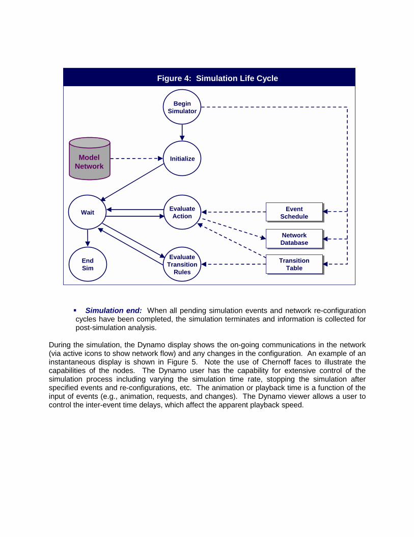
� Simulation end: When all pending simulation events and network re-configurationcycles have been completed, the simulation terminates and information is collected forpost-simulation analysis.
During the simulation, the Dynamo display shows the on-going communications in the network(via active icons to show network flow) and any changes in the configuration. An example of aninstantaneous display is shown in Figure 5. Note the use of Chernoff faces to illustrate thecapabilities of the nodes. The Dynamo user has the capability for extensive control of thesimulation process including varying the simulation time rate, stopping the simulation afterspecified events and re-configurations, etc. The animation or playback time is a function of theinput of events (e.g., animation, requests, and changes). The Dynamo viewer allows a user tocontrol the inter-event time delays, which affect the apparent playback speed.
Figure 4: Simulation Life Cycle
EventSchedule
ModelNetwork
BeginSimulator
Initialize
EvaluateAction
EvaluateTransition
Rules
NetworkDatabase
TransitionTable
EndSim
Wait

3.0 Sensor and Fusion Process Modeling
We have previously described the dynamic model used for the IADS communications network.However, it is still necessary to model the sensor performance and the performance of the datafusion processing. Both of these types of models can be incorporated into the Dynamocommunications network model by treating the sensor performance and the fusion algorithmsas transfer functions associated with the IADS nodes.
The current focus for Dynamo is to model the performance of radar and the effects of terrain onsignal propagation. Extensive research has been performed to develop analytic models ofradar performance. Farina and Pardini (1980) provide a survey of techniques. Dynamo uses avariation of the radar equation and Sterling’s expressions for modeling the probability ofdetection for a specified target at a specified sensor-to-target range. In addition, the effects ofterrain on the signal propagation are modeled. Figure 6 shows an example of the detectioncontours for radar in terrain as a function of target altitude. Additional sensor performancemodels are currently being implemented.
Figure 5: Example of an Instantaneous Dynamo Display

Models for the track-to-track data fusion are currently being implemented in a separatecomputer program named BORG (Bounded Operational Re-Grouping). The models are basedon the covariance error analysis approach described by Hall (1992). A key issue in theuncertainty modeling will involve the representation of the effects of delays in thecommunications network. These delays translate into increases in the uncertainty of the statevector (as it is propagated forward in time by the equation of motion) and potential biases.Effects related to miss-correlation induced by the combination of time delays and targetmaneuvering are still under investigation. Other effects include issues such as the correlationbetween tracks generated by multiple nodes in the IADS for the same target. This modelingeffort represents work still in progress.
4.0 Summary
This paper has described a dynamic simulation capability to accurately predict the performanceof integrated air defense systems. The Dynamo model allows a user to specify an IADS and toexecute simulations using a scripted set of political and environmental events. The modelprovides a means to predict the performance of the IADS communications network, the sensors,and the data fusion processing. Dynamo accounts for potential failure conditions in the IADScommunications system and nodes, and models the dynamics of the IADS reconfigurations inresponse to these conditions. This tool kit should be useful in determining how well an IADScan detect, characterize, track, and identify tactical entities such as aircraft and UAVs. Inaddition, the tool kit can be used for analyzing the vulnerabilities of an IADS to failureconditions.
Figure 6: Example of Terrain Effects on Radar Detection

5.0 References
D. L. Hall, Mathematical Techniques in Multi-Sensor Data Fusion, Artech House, Inc., Norwood,MA, 1992.
E. Waltz and J. Llinas, Multisensor Data Fusion, Artech House, Inc., Norwood, MA, 1990.
D. L. Hall and J. Llinas, “An introduction to multisensor data fusion”, Proceedings of the IEEE,vol. 85, No. 1, January 1997.
D. L. Hall and R. Linn, “A survey of data fusion systems”, Proceedings of the SPIE Conferenceon Data Structures and Target Classification, April 1991, Vol. 1490, Orlando, Florida, pp. 13-36.
R. Jaffee, S. Thode, J. A. Gauss, and F. A. Perry, “Evaluation of correlation and trackingalgorithms for transition from research and development to production”, DFS-91 Proceedings ofthe 1991 Joint Service Data Fusion Symposium, 7-11 October 1991, pp. 483-501.
T. O. Wolff, and D. Fixsen, “Standards, metrics, benchmarks, and Monte-Carlo: evaluatingmulti-sensor fusion systems”, DFS-91 Proceedings of the 1991 Joint Service Data FusionSymposium, 7-11 October 199, pp. 393-446.
J. L. Drury, “Evaluating automatic track-to-track correlation (ATTC) algorithm performance in astressful track data fusion/dissemination environment”, DFS-91, Proceedings of the 1991 JointService Data Fusion Symposium, 7-11 October 1991, pp. 524-536.
G. A. Schweiter and W. R. Stromquist, “The effect of sensor quality on tracker/correlatorperformance”, DFS-90 Proceedings of the 1990 Joint Service Data Fusion Symposium, 15-18May 1980, pp. 198-222.
T. R. Broida, L. R. Dean, T. T. Nguyen, R. A. Ribas, “Performance prediction and structuredbranching for multiple sensor tracking systems”, DFS-89, Proceedings of the 1989 Tri-ServiceData Fusion Symposium, Laurel, MD, pp. 195-202.
B. Belkin, G. A. Schweiter, and R. A. Wenocur, “Predictive models of false alarms”, DFS-88,Proceedings of the 1988 Tri-Service Data Fusion Symposium, Vol. 1, 17-19 May, 1998, JohnsHopkins University Applied Physics Laboratory, Laurel, MD, pp. 340-346.
B. Belkin and R. Wenocur, “An analytic model for the effect of false reports on surveillancetracking”, DFS-87, Proceedings of the 1987 Tri-Service Data Fusion Symposium, Vol. 1, 9-11June 1987, Johns Hopkins Applied Physics Laboratory, Laurel, MD, pp. 635-640.
S. Blackman, Multi-target Tracking with Radar Applications, Artech House, Inc., Norwood, MA,1987.
R. V. Denton, E. I. Alcaraz, J. P. Knopow, J. Llinas, and K. J. Hintz, “Towards modern sensormanagement systems”, DFS-93 Proceedings of the Sixth Joint Services Data FusionSymposium, Vol. 1, 14-18 June, 1993, pp. 659-678.

S. Music, “Comparison of sensor management strategies for detection and classification,”Proceedings of the 9th National Symposium on Sensor Fusion, Vol. 1, 12-14 March 1996, ERIM,Ann Arbor, MI, pp. 367-394.
http://www.javaapplets.com/frmain.htm
http://www.opnet.com
A. Farina and S. Pardini, “Survey of radar data-processing techniques in air-traffic-control andsurveillance systems”, IEE Proceedings, Vol. 7, No. 3, June 1980, pp. 189-202.