dynapac ca 251 maintenance - stephenson...
TRANSCRIPT
Box 504, SE-371 23 Karlskrona, SwedenTelephone +46 455 30 60 00
Telefax +46 455 30 60 30
DYNAPACCA 251
M251-1EN1
MAINTENANCE


1CA 251 M251-1EN1
Vibratory rollerCA 251
MaintenanceM251-1EN1, November 1999
Diesel engine:Cummins 6BT 5.9
These instructions apply from:CA 251 PIN (S/N) *58313611*CA 251A PIN (S/N) *58313688*
We reserve the right to change specifications without notice.Printed in Sweden.
KEEP THIS
MANUAL
AVAILABLE F
OR
FUTURE USE
The CA 25-family consists of rollers CA 251, Std, D, PD and CA 251A.These rollers are designed for the compaction of roads, airfields, dams and similarconstructions. The CA 251A compacts asphalt, roller concrete, base courses and
sub-base courses efficiently and with high capacity.
Separate information is available on request concerning accessories and extra equipment.
2 CA 251 M251-1EN1
CONTENTS
PageLubricants, symbols .............................................................................................. 3Specifications .................................................................................................... 4, 5Maintenance points ............................................................................................... 6Maintenance measures ..................................................................................... 7, 8Every 10 hours of operation (daily) ............................................ 7, 9, 10, 11, 12, 13Every 50 hours of operation (weekly) ..................................................7, 14, 15, 16Every 250 hours of operation (monthly) ......................................... 8, 17, 18, 19, 20Every 500 hours of operation (every three months)...................................8, 20, 21Every 1000 hours of operation (every six months) .............................. 8, 22, 23, 24Every 2000 hours of operation (yearly) ................................................8, 25, 26, 27Long-term parking ............................................................................................... 28Special instructions ............................................................................................. 29Electrical system................................................................................................. 30
Safety instructions – Personal safety.
Special caution – Machine or component damage.
Read the entire manual before starting any service work.
Ensure that ventilation (extraction) is adequate if the engine is run indoors.
It is essential that the machine is cared for in a proper manner to ensure satisfactory ope-ration. Keep the machine clean to facilitate quick and timely detection of any leakage, loosebolts and loose connections.
Make a habit each day, before starting up, of checking the roller to detect any leakage ordamage. Also check the ground underneath the roller, where it is most often easier todetect any leakage.
TAKE CARE OF THE ENVIRONMENTDo not leave behind any oil, fuel or other substances that are detrimental to theenvironment.
This manual contains instructions for periodic measures that should normally be carried outby the operator.
The manufacturer’s instructions noted in the engine manual also apply. This isplaced under a separate flap in the product folder for the roller.
WARNING SYMBOLS
GENERAL

3CA 251 M251-1EN1
LUBRICANTS AND SYMBOLS
Always use high-quality lubricants in theamounts recommended. Too much grease or oilcan cause overheating and subsequentincreased wear.
ENGINE OIL, Shell Rimula SAE 15W/40 or equivalent.ambient temperature -10°C - +50°C API Service CD/SE, CD/SF
HYDRAULIC FLUID,ambient temperature -10°C - +40°C Shell Tellus Oil TX68 or equivalent.ambient temperature higher than +40°CShell Tellus Oil T100 or equivalent.
TRANSMISSION OIL,ambient temperature-15°C - +40°C Shell Spirax SAE 80W/90, HD API, GL-5ambient temperature higher than+40°C Shell Spirax HD85W/140 or equivalent.
DRUM-CASSETTE OIL,All temperatures Synthetic oil MOBIL SHC 629.
DRUM OIL, (CA 251A)All temperatures Shell Spirax SAE 80W/90, HD API, GL-5
GREASE Shell Calithia EPT2 or equivalent.Shell Malleus GL95 or equivalent for thearticulation.
FUEL See engine manual.
COOLANT Shell Anti Freeze 402 or equivalent.50/50 mixture with water Anti-freeze down to about -35ºC.
Engine, oil level Air filter
Engine, oil filter Battery
Hydraulic reservoir, level Tyre pressure
Hydraulic fluid, filter Sprinkler
Transmission, oil level Sprinkler water
Lubricating oil Coolant, level
Fuel filter Recycling
Other lubricants are required for driving inextremely high or low ambient temperatures.See chapter “Special instructions”, or consultSvedala.
50/50

4 CA 251 M251-1EN1
SPECIFICATIONS
Std D PD A
Weight EN500-1, standard equipped roller, kg (lbs) 9 550 9 750 11 150 10 000(21,054) (21,495) (24,581) (22,046)
Length, standard equipped roller, mm (in) 5 380 5 380 5 450 5 532(11,861) (11,861) (11,861) (11,861)
Width, standard equipped roller, mm (in) 2 373 2 373 2 373 2 373(5,232) (5,232) (5,232) (5,232)
Height, standard equipped roller, mm (in) 2 175 2 175 2 230 2 175(4,795) (4,795) (4,916) (4,795)
Height, “ with ROPS, mm (in) 2 895 2 895 2 945 2 895(6,382) (6,382) (6,492) (6,382)
Height, “ with cab, mm (in) 2 800 2 800 2 850 2 800(6,173) (6,173) (6,283) (6,173)
Weight and sizes CA 251
Fluid volumes Litre (gal or qts)
Rear axle:• Differential ...................................12 l (12.7 qts)• Planetary gearing ........................1,7 l/side (1.8 qts/side)Pump drive/transfer gearbox .........1,5 l (1.6 qts)Drum drive/Drum gear (D,PD).......2,8 l (3.0 qts)Cassette, vibration generator ........A 27 l/side (7.1 gal), 2,7 l/side (2.8 qts) cassetteHydraulic reservoir ........................90 l (23.8 gal)Fluid in hydraulic system ...............Std, A 26 l (6.9 gal), D, PD 25 l (6.6 gal)Lubricating oil, diesel engine ..........16 l (4.2 gal)Coolant, diesel engine ...................27 l (7.1 gal)Fuel tank ........................................265 l (70 gal)Water tank(A) ................................480 l (127 gal)Emulsion tank(A) ...........................10 l (10.6 qts)
Electrical system
Battery ............................. 12 V, 160/170 AhAlternator ......................... 12 V, 95/105 AFuses .............................. 8 A
Compaction data CA 251
Std D PD A
Static linear load ...................... kg/cm (pli) 23,8 (133.3) 24,7 (138.3) - 26,1 (146.2)Amplitude (High) ...................... mm (in) 1,75 (0.07) 1,75 (0.07) 1,63 (0.06) 0,8 (0.031)Amplitude (Low) ....................... mm (in) 0,85 (0.033) 0,85 (0.033) 0,79 (0.031) 0,4 (0.015)Frequency (High ampl.) ........... Hz (vpm) 30 (1,800) 30 (1,800) 30 (1,800) 45 (2,700)Frequency (Low ampl.) ........... Hz (vpm) 33 (1,980) 33 (1,980) 33 (1,980) 45 (2,700)Centrifugal force (High ampl.) ..... kN (lb) 203 (45,675) 203 (45,675) 249 (56,025) 187 (42,075)Centrifugal force (Low ampl.) ..... kN (lb) 119 (26,775) 119 (26,775) 146 (32,850) 94 (21,150)
Tyres CA 251 CA 251A
Tyre size 23.1x26 8 ply 16.9x30 6 plyTyre pressure 110-150 kPa (1,1-1,5 kp/cm2) 110 kPa (1,1 kp/cm2)
As extra equipment the tyres can be filled with liquid (extra weight up to 600 kg(1,323 lbs)). In connection with service remember the extra weight that this entails.

5CA 251 M251-1EN1
The ROPS bolts are always to be torque-tightened dry.Bolt size: M24Strength class: 8,8Tightening torque: 640 Nm
ROPS
Tightening torque Tightening torque in Nm (lbf.ft) for oiled bolts tightenedwith a torque wrench.
Hydraulic systemOpening pressure (MPa)
Drive system 35Supply system 2Vibration system 35Steering system 14Brake release 1,5
Measured acoustic pressure level, LpA, on hardbase and vibration switched OFF:
Cummins: LpA: 92 dB(A)Cummins with cab: LpA: 84 dB(A)
Noise level – Operator’s station(ISO 6394)
Measurements taken with vibration ON and on foam-rubber mat (Limit value 0.5 m/s2):
Machine Operator’s O perator’s platformvibration level seat (m/s 2)* floor (m/s 2)**
CA 251Std./D 0,39 0,31+ ROPS 0,29 0,33+ cab 0,21 0,17+ ROPS and cab 0,16 0,21
CA 251A 0,05 0,09+ ROPS 0,04 0,04
* Sum of acceleration in the operator’s seat.** Maximum acceleration in floor in z-axis.
Whole body vibration– Operator’s station (ISO 2631)
(Hand/arm - steering wheel and F/Rlever vibration is less than the limitvalue, 2.5 m/s2.)
Measured acoustic power level, LpA, on hard baseand vibration switched OFF:
Cummins: LwA: 112 dB(A)
Acoustic power level –Surroundings(SS 4591010)
M STRENGTH CATEGORY
thread 8.8 (Grade 5) 10.9 (Grade 8)
M4 2,5 (1.8) 3,4 (2.5)M5 4,9 (3.6) 7,0 (5.2)M6 8,4 (6.2) 12 (8.9)M8 21 (15.5) 28 (20.7)M10 40 (29.5) 56 (41.3)M12 70 (51.6) 98 (72.3)M16 169 (124.7) 240 (177)M20 330 (243.4) 470 (346.7)M24 570 (420.4) 800 (590.1)M30 1130 (833.5) 1580 (1165.4)M36 1960 (1445.7) 2800 (2065.3)
6 CA 251 M251-1EN1
MAINTENANCE SCHEDULE
Read the entire manual before starting any service work. It isessential that the machine is cared for in a proper manner toensure satisfactory operation.
Keep the machine clean to facilitate quick and timelydetection of any leakage, loose bolts and loose connections.Make a habit each day, before starting up, of checking theroller and on the ground underneath it to detect any leakageor damage.
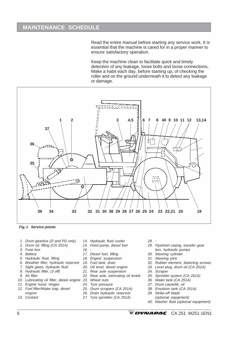
Fig. 1 Service points
1. Drum gearbox (D and PD only)2. Drum oil, filling (CA 251A)3. Fuse box4. Battery5. Hydraulic fluid, filling6. Breather filter, hydraulic reservoir7. Sight glass, hydraulic fluid8. Hydraulic filter, (3 off)9. Air filter
10. Lubricating oil filter, diesel engine11. Engine hood, hinges12. Fuel filter/Water trap, diesel
engine13. Coolant
14. Hydraulic fluid cooler15. Feed pump, diesel fuel16. -17. Diesel fuel, filling18. Engine suspension19. Fuel tank, drain20. Oil level, diesel engine21. Rear axle suspension22. Rear axle, lubricating oil levels23. Wheel nuts24. Tyre pressure25. Drum scrapers (CA 251A)26. Drain hydraulic reservoir27. Tyre sprinkler (CA 251A)
28. -29. Flywheel casing, transfer gear
box, hydraulic pumps30. Steering cylinder31. Steering joint32. Rubber element, fastening screws33. Level plug, drum oil (CA 251A)34. Scraper35. Sprinkler system (CA 251A)36. Water tank (CA 251A)37. Drum cassette, oil38. Emulsion tank (CA 251A)39. Strike-off blade
(optional equipment)40. Washer fluid (optional equipment)
1 2 3 4,5 6 7 8 40 9 10 11 12 13,14
39 34 33 32 31 30 38 29 28 27 26 25 24 23 22,21 20 19
36
35
37
15
1617
18

7CA 251 M251-1EN1
The periodic measures are to be carried out primarily inconformance with the stated hours of operation,secondarily for the periods daily, weekly, etc.
Remove all dirt before filling, when checkingoils and fuel, and when lubricating with oil orgrease.
The manufacturer’s instructions noted in theengine manual also apply.
MAINTENANCE MEASURES
Items in fig. 1 Measure See page Comments
Before starting up20 Check oil level in the engine See engine instruction manual.13 Check coolant level 9
Test the brakes 925,34 Check the scraper setting 10
40 Check/top up with washer fluid 1227,35 Inspect the sprinkler system (CA 251A) 13
After the day’s operation7 Check the hydraulic reservoir level 11
17 Refuel 1238 Fill the emulsion tank (CA 251A) 1236 Fill the water tank (CA 251A) 13
Every 10 hours of operation (daily)
Items in fig. 1 Measure See page Comments
9 Clean the filter element in the air cleaneror replace the main filter 14Check that hoses and connections are tight
24 Check the tyre pressure 144 Check the battery 15
31 Grease the steering joints 1630 Grease the steering cylinder brackets 1639 Grease the strike-off blade mechanism 16
Every 50 hours of operation (weekly)
After the first 50 hours of operation change all theoil filters and oil, except the hydraulic fluid.

8 CA 251 M251-1EN1
MAINTENANCE MEASURES
Items in fig. 1 Measure See page Comments
20 Change the engine oil See engine instruction manual.10 Change the engine oil filter See engine instruction manual.22 Check the oil level in the rear
axle/planetary gearing 1733,37 Check oil level in the drum/cassettes 17, 18
29 Check the oil level in the transfer gearbox 181 Check the oil level in the drum gearbox
(D and PD only) 1818,21 Inspect bolted joints 19
31 Inspect the rubber elements 20
Every 250 hours of operation (monthly)
Every 500 hours of operation (every three months)
Items in fig. 1 Measure See page Comments
8 Change the hydraulic filter 20Change the pre-fuel filter 21
11 Lubricate controls and pivoted joints 2114,28 Clean the outside of the hydraulic cooler 21
Replace fuel filter See engine instruction manual.
Every 1000 hours of operation (every six months)
Items in fig. 1 Measure See page Comments
26 Drain condensation from the hydraulic reservoir 226 Replace breather filter on the hydraulic reservoir 22
19 Drain condensation from the fuel tank 229 Replace main filter in the air cleaner 23
Check belt tension of the fan and alternator See engine instruction manual.Check engine valve clearance See engine instruction manual.
22 Change oil in the rear axle planetary gearing 2322 Change oil the rear axle differential 24
Items in fig. 1 Measure See page Comments
26 Change the hydraulic fluid 2529 Change oil in the transfer gearbox 25
2,37 Change oil in the drum/cassettes 25, 261 Change oil in the drum gearbox (D and PD only) 26
36 Clean the water tank (CA 251A) 2738 Clean the emulsion tank 27
Every 2000 hours of operation (yearly)

9CA 251 M251-1EN1
Brakes – Check
EVERY 10 HOURS OF OPERATION (DAILY)
11 24
10
Fig. 2 Radiator1. Filler cap
Check operation of the brakes as follows:
Drive the roller slowly forward.
Press down the reserve brake (11). The brake warninglamp (10) shall light and the roller shall stop.
After checking the brakes, put the forward/reverselever (24) in neutral before resetting the reserve brake.
Pull out the reserve brake knob.Fig. 4 Instrument panel
10. Brake warning lamp11. Emergency stop knob24. Forward/Reverse lever
Take great care if the radiator cap must beopened while the engine is hot. Danger ofbeing burned.
Steps or equivalent are to be used whenchecking the radiator.
Fill with coolant comprised of 50% water and 50% anti-freezing agent. See page 3 in these instructions andthe engine manual.
Change the coolant and flush the systemevery other year. Ensure that air has freepassage through the radiator.
Coolant level, check– Filling
Air circulation – Check
Fig. 3 Cooling air grille
1
Ensure that the engine has unimpeded circulation ofcooling air through the protective grille to the engine.

10 CA 251 M251-1EN1
EVERY 10 HOURS OF OPERATION (DAILY)
Scrapers (CA 251)– Checking, adjusting
2
1
Adjust the distance as follows:
Loosen all four screws, while holding the nut on theinside.
Set the scraper about 20 mm (0.79 in) from the drum.
Tighten the fastening screws.
Remember that the drum moves when themachine turns. If adjustments are made closerthan the recommended value the scrapersmay be damaged and cause increased wearof the drum.
Fig. 5 Scraper1. Fastening screws2. Scraper
Drum:
Check that the scrapers are intact, and adjust thedistance as follows:
Loosen all the fastening screws.
Set the scraper against the drum.
Tighten the fastening screws.
Tyres:
Check that the scrapers are intact, and adjust thedistance as follows:
The scraper blade (4) should lie against the tyre with a20-mm pre-tensioning of the spring (3). The pre-tensioning is to be set with the scraper tensioner (2).
For transport driving, release the scraper from the tyreand tension with the cotter (1).
Fig. 6 Scraper1. Fastening screws2. Scraper
2
3
4
Fig. 7 Tyre scraper1. Cotter2. Scraper tensioner3. Spring4. Scraper
1
1 2
Scrapers (CA 251A)– Checking, adjusting

11CA 251 M251-1EN1
EVERY 10 HOURS OF OPERATION (DAILY)
1
Place the roller on level ground and check that the oillevel is between the max. and min. marks in the sightglass (1).
Top up with hydraulic fluid according to the lubricantspecification if the level is too low.
Fig. 8 Hydraulic reservoir1. Sight glass
Hydraulic reservoir– Checking the fluid level
Diesel engine– Checking the oil level
Fig. 10 Engine compartment1. Oil dipstick
Place the roller on a level base. The engineis to be switched off and the parking brakeapplied for all checking and adjustmentson the roller unless stated otherwise.
Beware of hot parts of the engine and hotradiator when taking out the oil dipstick.Danger of being burned.
The dipstick is on the right-hand side of the engine.
Pull the dipstick (1) up and check that the oil level isbetween the upper and lower marks. See the enginemanual for further details.
1
Hydraulic reservoir – Filling
Fig. 9 Battery box1. Suction hose2. Protective plug3. Pump arm
Remove the cover on the right side under theoperator’s seat.
Take out the suction hose (1).
Clean the hose and screw off the protective plug (2).
Insert the hose into a barrel of fresh hydraulic fluid.
Attach the pump arm (3), and pump until the reservoir isfull according to the marks on the sight glass. Hydraulicfluid is pumped to the reservoir through a filter, soalways fill with fluid in this way.
3
1
2

12 CA 251 M251-1EN1
EVERY 10 HOURS OF OPERATION (DAILY)
Refuel every day at the end of work. Top up to thelower edge of the filler pipe. Use diesel fuel inaccordance with the engine manufacturer’sspecifications.
Stop the diesel engine. Short (press) thefiller gun against a non-insulated part ofthe roller before refuelling, and against thefiller pipe (1) while refuelling is in progress.
CA 251 holds 265 litre (70 gal) fuel.
Fuel tank – Refuelling
Check the level and fill the emulsion tank as required.The emulsion fluid is only for lubricating the tyres. Thepump and filter are located inside the cover at thebottom of the tank.
Remember the risk of freezing during thewinter. Empty the tank, pump and leads.
Emulsion tank (CA 251A)– Filling
2
1
Fig. 13 Left side of frame1. Emulsion tank2. Place for pump and filter
Fig. 12 Fuel tank1. Filler pipe
1
Washing fluid– Checking/Filling (Cab)
Fig. 11 Engine compartment1. Washer bottle
Open the right-hand cover of the engine compartmentand fill the washer fluid bottle (1).
Remember the risk of freezing during thewinter. Empty the tank, pump and leads.
1

13CA 251 M251-1EN1
EVERY 10 HOURS OF OPERATION (DAILY)
1 2 3 4
Dismantle the clogged nozzle. Blow the nozzle andstrainer clean with compressed air, or fit replacementparts, and clean the clogged parts at a later opportun-ity.
Wear protective goggles when workingwith compressed air.
Sprinkler system (CA 251A)Checking – Cleaning
Nozzle (CA 251A)Dismantling – Cleaning
Fill with clean water through the tank filter.
Ensure that the sprinkler nozzles (1) are not clogged.Clean them and the water filter if necessary.
1
2
Fig. 14 Water tank1. Nozzle2. Pump system
Fig. 15 Nozzle1. Sleeve2. Nozzle3. Seal4. Strainer
Take off the cover on the front frame beam and removethe screws.
The sprinkler system has two water pumps and filter.When cleaning, close the stop cock (3) and loosen thefilter housing (2). Clean the insert and the filter housingwith water.
Listen or put your hand on the water pump to checkthat it is working.
1 2 3
Fig. 16 Pump system1. Water pump2. Water filter3. Stop cock
Pump system (CA 251A)Checking – Cleaning

14 CA 251 M251-1EN1
Use compressed air at a maximum pressure of 0.7MPa (7 kp/cm2).
Blow up and down the paper pleats on the inside of thefilter element. Hold the nozzle at least 10 mm (0.39 in)from the paper pleats so as to avoid tearing the paper.
Change the main filter at the latest after 5cleanings.
Wear protective goggles when workingwith compressed air.
When the tyres are filled with liquid the air pressurevalve (1) must be set at “12 o’clock” when pumping.Check the tyre pressure with a pressure gauge.Min. tyre pressure = 110 kPa (1.1 kp/ cm2).Max. tyre pressure = 150 kPa (1.5 kp/cm2)Tyre pressure CA 251A: 110 kPa (1.1 kp/cm2)Check both tyres.
When changing the tyres it is important thatboth tyres have the same rolling radius (max.difference about 15 mm (0.59 in)). The no-spinequipment may otherwise be damaged.
Check tightening torque of the wheel nuts (2) at 550Nm (406 lbf.ft). Check both wheels and all nuts (appliesonly for a new machine or newly fitted wheel).
Replace or clean the main filter of the aircleaner when the warning lamp on the instru-ment panel lights at full engine revs.
Loosen the clamp (4) and take out the dust trap (3).
Loosen the wing nut at the centre of the filter and takeout the inner cover (5). Clean the dust trap with a cleanrag.
Loosen the wing nut and pull out the main filter (6).
Wipe the inside of the filter housing (1) and the inputtube with a clean rag.
Ensure that connections and hoses between the filterhousing and engine are intact and tight.
Clean the emptying slit (7) of the dust trap.
Replace the secondary filter (2) with a newone after every third replacement or thirdcleaning of the main filter. The secondary filtercannot be cleaned.
Air cleaner – Cleaningthe main filter element
EVERY 50 HOURS OF OPERATION (WEEKLY)
6 5 4 3
21
7
Fig. 17 Air cleaner1. Filter housing2. Secondary filter3. Dust trap4. Clamp5. Inner cover6. Primary filter7. Emptying slit
Tyres – Tyre pressureWheel nuts – Tightening
Fig. 19 Wheels1. Air valve2. Wheel nuts
1
Fig. 18 Main filter
Cleaning withcompressed air
2

15CA 251 M251-1EN1
Battery – Checking theelectrolyte level
EVERY 50 HOURS OF OPERATION (WEEKLY)
Never use an open flame when checking theelectrolyte level. Explosive gas is generatedwhen the alternator is charging.
Turn the knob (1).
Pull out the battery shelf.
Wipe the top of the battery dry.
Wear safety goggles. The battery containsacid. Rinse with water if splashed withelectrolyte.
Take off the cell caps and ensure that electrolyte isabout 10 mm (0.39 in) above the plates. Check thelevel of all cells. Top up with distilled water to the rightlevel if the level is low. If the air temperature is belowfreezing point the engine should be run for a whilebefore topping up with distilled water. There isotherwise a danger that the electrolyte will freeze.
Ensure that the ventilation holes in the cell cover arenot clogged. Then put the cover back on.
The cable shoes should be clean and well tightened.Clean corroded cable shoes and grease them withacid-free Vaseline.
Ensure always that the battery box isclosed and locked while driving.
When disconnecting the battery, alwaysdisconnect the negative cable first. Whenconnecting the battery, always connect thepositive cable first.
Get rid of discarded batteries in a proper way.Batteries contains lead which is detrimental tothe environment.
Before doing any electric welding on themachine, disconnect the battery earthcable and then all electrical connections tothe alternator.
Fig. 20 Battery shelf1. Knob
1
1
Fig. 21 Battery shelf1. Battery
Battery cell
Fig. 22 Electrolyte level in battery1. Cell cap2. Electrolyte level3. Plate
1
2
3
10 mm(0.39 in)

16 CA 251 M251-1EN1
Strike-off blade – Lubrication
Fig. 25 Strike-off blade1. Grease nipples
Always lower the blade when leaving/parking the machine.
Lower the blade.
Wipe the grease nipples on both sides of the machine.
Grease each nipple (1) with four strokes of the greasegun. Ensure that grease penetrates the bearings. Usegrease according to the lubricant specification on page3.
1
EVERY 50 HOURS OF OPERATION (WEEKLY)
Nobody is to be allowed near the articula-tion joint when the engine is running. Dan-ger of being crushed.
Turn the steering wheel fully to the left to gain access toall five nipples on the right side of the steering system.
Wipe the nipples clean from grease and dirt.
Grease each nipple with five strokes of the grease gun.
Use grease according to the lubricantspecifications.
1
2
Steering joint – Steeringcylinders Lubrication
Fig. 23 Steering joint. Right side1. Grease nipples, steering joint
(3 off)2. Grease nipples, cylinder mount
(2 off)
1
2
Fig. 24 Steering joint, left side1. Grease nipples, steering joint2. Grease nipples, cylinder mount
Steering joint – Lubrication Turn the steering wheel fully to the right to gain accessto the three grease nipples on the left steering cylinder.Allow a little grease to remain on the nipples aftergreasing. This will prevent contamination from enteringthe nipples.
Wipe the nipples clean from grease and dirt.
Grease each nipple with five strokes of the grease gun.Ensure that grease penetrates the bearings.
If grease does not penetrate the bearings itmay be necessary to relieve the articulationjoint with a jack while repeating the greasingprocess.
1
2
1
2

17CA 251 M251-1EN1
EVERY 250 HOURS OF OPERATION (MONTHLY)
2
3 1
Applies to both sides of the drum, ie, two checks.
Place the roller on a level surface so that the level pinis at the top of the frame beam.
Unscrew the level plug (3) (small hexagon) a few turns.If the level is correct oil should now flow from the plug.
Top up with transmission oil as required, see thespecification. Fill through the filler plug (2) (large hexa-gon).
Fig. 28 Right side of drum1. Dipstick2. Filler plug3. Level plug
Drum (CA 251A)– Checking the oil level
Rear axle differential– Checking the oil level
Never work underneath the roller when theengine is running. Park on a level surface.Chock the wheels.
Ensure that the roller is level.
Remove the level plug (1) and check that the oil levelreaches the lower edge of the plug hole. Top up to theright level through the plug (1) if the level is low. Usetransmission oil according to the lubricant specification.
Run the roller on a level surface until the plug (1) in theplanetary gearing is at 9 o’clock.
Remove the level plug and check that the oil levelreaches the lower edge of the plug hole. Top up to theright level through the plug (1) if the level is low. Usetransmission oil. See lubricant specification on page 3.
Check the oil level in the same way in the otherplanetary gearing of the rear wheel.
1
1
Fig. 26 Level check – differential housing1 Level/Filler plug
Rear axle planetary gearing– Checking the oil level
Fig. 27 Level check – differential gearing1 Level/Filler plug
18 CA 251 M251-1EN1
EVERY 250 HOURS OF OPERATION (MONTHLY)
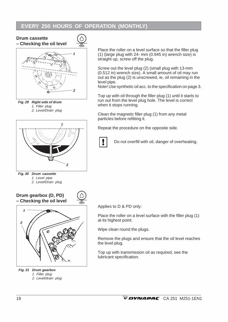
Drum gearbox (D, PD)– Checking the oil level
Applies to D & PD only:
Place the roller on a level surface with the filler plug (1)at its highest point.
Wipe clean round the plugs.
Remove the plugs and ensure that the oil level reachesthe level plug.
Top up with transmission oil as required, see thelubricant specification.
2
1
Fig. 31 Drum gearbox1. Filler plug2. Level/drain plug
Fig. 29 Right side of drum1. Filler plug2. Level/Drain plug
Place the roller on a level surface so that the filler plug(1) (large plug with 24- mm (0.945 in) wrench size) isstraight up, screw off the plug.
Screw out the level plug (2) (small plug with 13-mm(0.512 in) wrench size). A small amount of oil may runout as the plug (2) is unscrewed, ie, oil remaining in thelevel pipe.Note! Use synthetic oil acc. to the specification on page 3.
Top up with oil through the filler plug (1) until it starts torun out from the level plug hole. The level is correctwhen it stops running.
Clean the magnetic filler plug (1) from any metalparticles before refitting it.
Repeat the procedure on the opposite side.
Do not overfill with oil, danger of overheating.
Drum cassette– Checking the oil level
1
2
Fig. 30 Drum cassette1. Level pipe2. Level/Drain plug
1
2
19CA 251 M251-1EN1
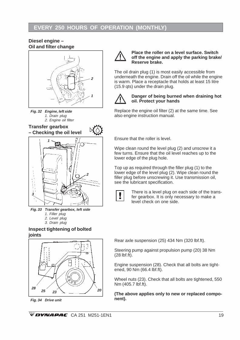
Place the roller on a level surface. Switchoff the engine and apply the parking brake/Reserve brake.
The oil drain plug (1) is most easily accessible fromunderneath the engine. Drain off the oil while the engineis warm. Place a receptacle that holds at least 15 litre(15.9 qts) under the drain plug.
Danger of being burned when draining hotoil. Protect your hands
Replace the engine oil filter (2) at the same time. Seealso engine instruction manual.
EVERY 250 HOURS OF OPERATION (MONTHLY)
1
3
2
Ensure that the roller is level.
Wipe clean round the level plug (2) and unscrew it afew turns. Ensure that the oil level reaches up to thelower edge of the plug hole.
Top up as required through the filler plug (1) to thelower edge of the level plug (2). Wipe clean round thefiller plug before unscrewing it. Use transmission oil,see the lubricant specification.
There is a level plug on each side of the trans-fer gearbox. It is only necessary to make alevel check on one side.
Fig. 33 Transfer gearbox, left side1. Filler plug2. Level plug3. Drain plug
Inspect tightening of boltedjoints
2825 20
Rear axle suspension (25) 434 Nm (320 lbf.ft).
Steering pump against propulsion pump (20) 38 Nm(28 lbf.ft).
Engine suspension (28). Check that all bolts are tight-ened, 90 Nm (66.4 lbf.ft).
Wheel nuts (23). Check that all bolts are tightened, 550Nm (405.7 lbf.ft).
(The above applies only to new or replaced compo-nent).
23
Fig. 34 Drive unit
Transfer gearbox– Checking the oil level
Fig. 32 Engine, left side1. Drain plug2. Engine oil filter
Diesel engine –Oil and filter change
1
2

20 CA 251 M251-1EN1
Loosen the breather filter on top of the reservoir so thatpressure inside is eliminated.
Remove the hydraulic filters (1), (2) and (3) and scrapthem. They are of the expendable type and cannot becleaned.
Ensure that the old gaskets do not remain onthe filter holders. Leakage may otherwiseoccur between the new and the old gaskets.
Thoroughly clean the sealing surfaces of the filterholders.
Apply a thin coat of fresh hydraulic fluid on the newfilter gaskets.
Tighten the filters by hand.
First screw on until the filter seal lies againstthe filter holder. Then screw a further half turn.Do not tighten the filter too hard, it couldotherwise damage the gasket.
Start the engine and ensure that there is no leakage ofhydraulic fluid from the filters.
Ensure that ventilation (extraction) isadequate if the engine is run indoors. (Riskof carbon monoxide poisoning).
Check the fluid level in the sight glass (4) and top up asrequired.
2
3
1 4
Fig. 36 Hydraulic reservoir1. Suction filter, propulsion2. Suction filter, vibr.3. Return filter, cooling circuit4. Sight glass
Hydraulic filter – Replacement
EVERY 500 HOURS OF OPERATION (EVERY THREE MONTHS)
Check all rubber elements (1), replace all of theelements if more than 25% of them on one side of thedrum are cracked deeper than 10–15 mm (0.39–0.59 in).
Use the blade of a knife or pointed object to assistwhen checking.
Ensure that the fastening screws (2) are tightened.
With a calliper gauge, measure the length ofthe rubber element including the mountingplates. See separate workshop instructions ifthe size is more than 76 mm (3 in).
Fig. 35 Drum, vibration side1. Rubber element2. Fastening screws
2
1
Rubber elements and fasteningscrews – Check
Max 76 mm (3 in)
EVERY 250 HOURS OF OPERATION (MONTHLY)

21CA 251 M251-1EN1
Controls and pivoted jointsLubrication
EVERY 500 HOURS OF OPERATION (EVERY THREE MONTHS)
Lubricate the engine hood hinges (1), F/R lever andslide rails of the operator’s seat with grease, othermoving parts and controls with oil. Grease the cab doorhinges. See lubricant specification.
1
Fig. 38 Engine hood2. Hinges
Hydraulic fluid coolerChecking – Cleaning
1
Ensure that the flow of air through the radiator isunobstructed. Clean a dirty radiator with water orcompressed air.
Wear protective goggles when workingwith compressed air.
If possible, blow or flush in the opposite direction to theflow of air. Cover electric components.
Check after cleaning that seals and noise absorbentsare undamaged.
Fig. 39 Engine compartment1. Hydraulic fluid cooler
Pre-fuel filter – Replacement
1
Fig. 37 Engine, left side1. Pre-fuel filter
Release the hose clips and remove the filter. Fit thenew fuel filter and make certain the direction of flow iscorrect. The arrow should point from the tank.

22 CA 251 M251-1EN1
Water and sediment in the fuel tank is drained via thedrain plug in the bottom of the fuel tank.
Take great care when draining. Do not dropthe plug so that all the fuel runs out.
Draining is to be done after the roller has stood stillduring a long period, eg, overnight. The fuel levelshould be as low as possible.
The roller should preferably have stood sloping so thatwater and sediment is concentrated over the drain plug.
Drain as follows:
Hold a suitable receptacle under the plug (1).
Loosen the plug and drain off the water and sedimentuntil only pure fuel flows from the plug. Tighten the plugagain.
EVERY 1000 HOURS OF OPERATION (EVERY SIX MONTHS)
Fuel tank – Draining
Hydraulic reservoir – Draining
Fig. 40 Hydraulic reservoir, underneath1. Drain cock2. Plug
2
1
1
Fig. 41 Hydraulic reservoir1. Breather filter
Fig. 42 Fuel tank1. Drain plug
Screw off the breather filter (1) and discard it. Fit a newone.
Condensation in the hydraulic reservoir is drained viathe drain plug (1). Draining is to be done after the rollerhas stood still during a long period – eg, after standingstill overnight.
Drain as follows:
Hold a suitable receptacle under tap.
Remove the plug (2).
Open the tap (1) and drain off the condensation.
Close the drain tap.
Refit the plug.Hydraulic reservoir– Breather filter
1
23CA 251 M251-1EN1
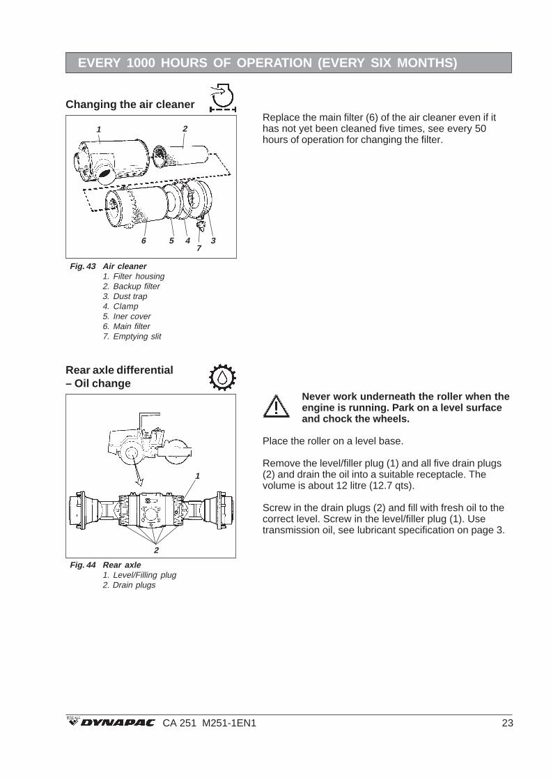
Changing the air cleaner
6 5 4 3
21
7
Fig. 43 Air cleaner1. Filter housing2. Backup filter3. Dust trap4. Clamp5. Iner cover6. Main filter7. Emptying slit
Replace the main filter (6) of the air cleaner even if ithas not yet been cleaned five times, see every 50hours of operation for changing the filter.
EVERY 1000 HOURS OF OPERATION (EVERY SIX MONTHS)
Never work underneath the roller when theengine is running. Park on a level surfaceand chock the wheels.
Place the roller on a level base.
Remove the level/filler plug (1) and all five drain plugs(2) and drain the oil into a suitable receptacle. Thevolume is about 12 litre (12.7 qts).
Screw in the drain plugs (2) and fill with fresh oil to thecorrect level. Screw in the level/filler plug (1). Usetransmission oil, see lubricant specification on page 3.
Fig. 44 Rear axle1. Level/Filling plug2. Drain plugs
Rear axle differential– Oil change
2
1

24 CA 251 M251-1EN1
EVERY 1000 HOURS OF OPERATION (EVERY SIX MONTHS)
1
Fig. 46 Planetary gearing/filling position1. Plug
Place the roller on a level surface with the plug (1) at itslowest position.
Unscrew this plug and drain the oil into a suitablereceptacle. The volume is about 2 litre (4.23 qts). Placethe roller on a level surface with the plug (1) at itslowest position.
Rear axle planetary gearing– Oil change
Fig. 45 Planetary gearing /draining position1. Plug
1
Run the roller so that the plug is at 9 o’clock.
Fill oil through the plug to the lower edge of the hole.
Screw in the plug and repeat the procedure on theother side. Use transmission oil. See lubricantspecification on page 3.

25CA 251 M251-1EN1
EVERY 2000 HOURS OF OPERATION (YEARLY)
Arrange a receptacle to collect the oil. The receptacleshould hold at least 100 litre (26.5 gal).
An empty oil barrel or similar vessel at the side of theroller would be suitable. Allow the fluid to run from thedrain tap (1) through a hose to the oil barrel.
Fill with fresh hydraulic fluid according to instructionsunder the heading “Hydraulic reservoir – checking thelevel”. Change all the hydraulic filters. See under theheading “Hydraulic system – changing the filters”.
Ensure that ventilation (extraction) isadequate if the engine is run indoors. (Riskof carbon monoxide poisoning).
Check the level and top up as required.
Hydraulic reservoir– Changing the fluid
Never work underneath the roller when theengine is running. Park on a level surface.Chock the drum and wheels if necessary.
Unscrew the drain plug (3) and drain off the oil.
Refit the plug.
Remove the level plug (2) and fill with fresh gearbox oilthrough the filler plug (1). Fill slowly so that the oil levelhas time to even out.
Refit the plugs (1) and (2) when the level is correct.
1
3
2
Fig. 48 Transfer gearbox, left side1. Filler plug2. Level plug3. Drain plug
Fig. 47 Hydraulic reservoir, underneath1. Drain cock
1
Transfer gearbox– Oil change
Place the roller on a level surface so that the filler plug(1) (large plug with 24-mm (0.945 in) wrench size) isstraight up. Place a receptacle that will hold 5 litreunder the level/drain plug (2).
Unscrew the filler plug (1). Unscrew the drain plug (2)(large plug with 24-mm (0.945 in) wrench size).
Allow all the oil to run out. Then unscrew the level plug(13-mm (0.512 in) wrench size) from the drain plug (2).Fit the drain plug with level pipe in the cassette. Fill withfresh synthetic oil according to instructions under theheading “Drum cassette – checking the oil level”.
Clean the magnetic filler plug (1) from any metalparticles before refitting it.
Repeat the procedure on the opposite side.
Drum cassette– Oil change
Fig. 49 Right side of drum1. Filler plug2. Level/Drain plug
1
2

26 CA 251 M251-1EN1
EVERY 2000 HOURS OF OPERATION (YEARLY)
Before changing the oil it is important that theroller has been run long enough for the oil tobe warm and easy flowing before being drai-ned. Any contamination will thus also flow outwith the oil. Observe cleanliness andremember that the roller is to be level.
Applies to D & PD only:
Place the roller on a level surface so that the drain/levelplug is straight down.
Wipe clean round the plugs.
Place a receptacle under the drain plug (2) and drain offthe oil. The receptacle is to hold about 5 litre (5.3 qts).
Also remove the filler plug (1).
Run the roller back so that the filler plug is at its highestposition.
Fill with oil until the level reaches the level plug hole.Use transmission oil according to the lubricantspecification.
The plugs are magnetic and any metal particles mustbe wiped off before refitting.
Drum gearbox (D, PD)– Oil change
Fig. 51 Drum gearing/Position whendraining1. Filler plug2. Drain/level plug
1
2
1
2
Fig. 52 Filling the oil1. Filler plug2. Drain/level plug
Fig. 50 Drum position when draining1. Drain plug2. Level plug
2
1
Applies to both sides of the drum, ie, two checks.
Place the roller on a level surface and drive the rolleruntil the drain plug (1) (large hexagon) is straight down.
Unscrew the plug (1) and drain off the oil. Observe thatthe volume of oil is 27 litre (7.1 gal).
Drain off oil from the other side of the roller.
See under every 250 hours of operation, heading“Drum – Checking the oil level”, when the drum is to befilled with oil.
Drum (CA 251A)– Oil change

27CA 251 M251-1EN1
EVERY 2000 HOURS OF OPERATION (YEARLY)
Water tank (CA 251A)– Draining, cleaning
Emulsion tank (CA 251A)– Draining, cleaning
Remember the risk of freezing during thewinter. Empty the tank, pump and leads.
1. Remove the drain plug (1) and allow the water to runout.
2. Clean the inside of the tank with water and a suitabledetergent for plastic surfaces.
3. Refit the plug and check for tightness.
The water tank is made of plastic(polyethylene) which is recyclable.
Fig. 53 Water tank, underneath1. Drain plug
1
Fig. 55 Left side of frame1. Water filter
1
The easiest way to empty the emulsion tank is toscrew off the water filter.
The emulsion tank is made of plastic(polyethylene) which is recyclable.
1 2 3
Fig. 54 Pump system1. Water pump2. Stop cock
Water pump (CA 251A)– Draining
Empty the water tank (1) via the tap (2).

28 CA 251 M251-1EN1
LONG-TERM PARKING
The following instructions should be followedfor long-term parking:
The measures apply for a period of up to 6months.
The items marked * must be restored beforeusing the roller.
Diesel engine
Battery
❊ See manufacturer’s instructions in the engine ma-nual that accompanies the roller.
❊ Remove the battery from the roller, clean it, checkthat the electrolyte level is correct and trickle chargethe battery once a month.
❊ Cover the air cleaner or its opening with plastic ortape. Cover the exhaust opening. This is necessaryto prevent moisture from entering the engine.
Fill the fuel tank to prevent condensation andconsequent corrosion.
Drain off any condensation from the hydraulicreservoir.
❊ Empty the water tank completely, also hoses, filterhousing and the water pump. Also remove all sprink-ler nozzles for the drum and wheels.
Grease the steering-joint bearings and both bearingsof the steering cylinder. Also grease the engine hoodhinges, revs control and the forward/reversemechanism.
Ensure that tyre pressure is at least 150 kPa (1.5kp/cm2), 110 kPa (1.1 kp/cm2) on the CA 251A.
❊ Lower the instrument shield on the steering column.Cover the entire roller with a tarpaulin. The tarpaulinmust be free from the ground. Store the rollerindoors if possible, preferable on premises with aneven temperature.
Fig. 56 Roller protected against theweather
Air cleaner, exhaust pipe
Fuel tank
Hydraulic reservoir
Sprinkler system (CA 251A)
Steering cylinder, hinges, etc.
Tyres
Hoods, tarpaulin
29CA 251 M251-1EN1
SPECIAL INSTRUCTIONS
The temperature limits apply to standard versions ofthe roller.
Rollers that are fitted with additional equipment, suchas noise suppression, etc, may require extra observa-tion in the higher temperature ranges.
A water jet should not be aimed directly at thecap of the fuel tank or hydraulic reservoir. Thisis especially important when using a high-pressure jet.
Put a plastic bag over the filler cap of the fuel tank andsecure with a rubber band. This will prevent water fromentering the venting hole in the filler cap. This couldotherwise cause operational disturbance, eg, cloggedfilter. Do not spray water directly on electriccomponents or the instrument panel.
In the event of fire in the machine, use an ABE-powderfire extinguisher if possible. A BE type carbon dioxidefire extinguisher may also be used.
If the roller is equipped with a protective structure, ie,Roll Over Protective Structure, (ROPS), it must on noaccount be subjected to welding and holes must neverbe drilled in the structure. Never attempt to repair adamaged structure, it must be replaced with a new one.
When using an auxiliary battery to assist starting,always connect the positive terminal of the auxiliarybattery to the positive terminal of the roller battery, andnegative to negative.
Starting aid
Protective structure (ROPS)
Fire fighting
High-pressure washing
Temperature
Higher ambient temperaturemax. +50°C (122°F)
Standard oils and otherrecommended fluids
On leaving the factory the various systems andcomponents are filled with oil or fluid as indicated onpage 3. These can be used in temperatures from -10°C to + 40 °C (14°F to (104°F)). The followingrecommendations apply for operation in higher ambienttemperatures up to a maximum of +50°C (122°F):
The diesel engine can be run at this temperature usingthe normal oil but for other components the followingfluids shall be used:Hydraulic system: Shell Tellus Oil T100, or equivalent.Other components using transmission oil: Shell SpiraxHD 85W/140, or equivalent.

30 CA 251 M251-1EN1
ELECTRICAL SYSTEM
FusesThe machine is equipped with a 12 V electrical systemand an alternator.
Connect the battery to the correct polarity (- toearth). The cable between battery andalternator must not be disconnected when theengine is running.
Before doing any electric welding on themachine. Disconnect the battery earth cableand then all electric terminals to the alternator.
The electrical regulating and control system has 8 Afuses which are located in fuse boxes on the steeringcolumn, see maintenance schedule.
The lower fuse box is only provided on rollers that areequipped with driving lights, direction indicators andrear working lights.
Fig. 58 shows the fuse boxes and rated current offuses in the cab, if fitted. Fuses are of the flat pin type.
Fig. 59 Fuse box in cab (accessories)10A 1. Front working lights10A 2. Rear working lights3A 3. Front washer15A 4. Fan15A 5. Front wiper15A 6. Rear wiper3A 7. Interior lighting, Radio7,5A 8. Air conditioning
9. -10. -
3A 11. Hazard beacon25A 12. Cab heater
Fig. 58 Lower fuse box (accessories)13. Working lights, rear14. Parking lights, left15. Parking lights, right16. Direction indicator, left17. Direction indicator, right18. Dipped headlight, left19. Dipped headlight, right20. Main beam, left21. Main beam, right22. Brake lights, left23. Brake lights, right24. -
Fig. 57 Fuse boxes1. Vibration control2. Instruments3. Horn4. Fuse for stop solenoid, Cummins5. Hazard beacon6. -7. Brake valve8. Gear selector9. Sprinkler (CA 251A)10. -11. -12. Driving lights (optional equipment)
1 2 3 4 5 6 7 8 9 10 11 12
7 8 9 10 11 12
1 2 3 4 5 6
13 14 15 16 17 18 19 20 21 22 23 24