dywi drill hollow bar system - ebs geostructural · dywi® drill hollow bar system ... dywidag soil...
TRANSCRIPT

DYWI® Drill Hollow Bar SystemSoil Nails — Micro Piles — Ground Anchors — Rock Bolts
Reno RetRac Project, Reno, NV

22
Reno ranks among the US cities with the highest quality of life and the best environment for
families. In the past few years the city’s booming economy has also led to a strong increase in rail traffic, in particu-lar in downtown Reno. With the Reno ReTRAC Project (Reno Transportation Rail Access Corridor) the city of Reno wanted to eliminate traffic jams, accidents and emissions at at-grade rail crossings. For this reason, rail traffic was relocated below ground into a 3.3 km long and 10 m deep trough structure along the existing railroad line.
DYWI® Drill System secures Trough Structure for Railroad, Reno, USAThe Reno ReTRAC project in Reno, Nevada, USA
Owner City of Reno, Nevada, NV, USA +++ General Contractor Granite Construction, CA, USA +++ Design Team Leader Parsons, CA, USA +++ Project Management Jacobs Engineering Group, CA, USA +++ Sub Contractor (Shoring Contractor) Schnabel Foundation Co., CA, USADSI Services Supply of more than 8,000 R38 DYWI® Drill Hollow Bars supporting 180,000 SF of soil nail wall
i

33
General Notes ........................................................................................................... 4Technical Data........................................................................................................... 5Drill Bits ..................................................................................................................... 6DYWI® Drill Hollow Bar System - Installation............................................................ 7DYWIDAG Soil Nails .................................................................................................. 8Micro Piles ................................................................................................................. 9Temporary Ground Anchors.................................................................................... 10Rock Bolts & Spiles ................................................................................................. 11DYWI® Drill Hollow Bar System - Installation Accessories ..................................... 12Stressing and Testing ............................................................................................. 13References .............................................................................................................. 14
Contents
Details, dimensions and system designs are subject to change without notice.
Refer to installation manual for further details. www.dsiamerica.com
DYWI® Drill Bar Installation in Reno, NV
44
DYWI® Drill Hollow Bar System
General Notes
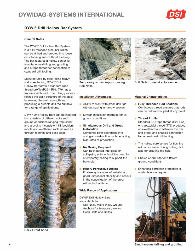
The DYWI® Drill Hollow Bar System is a fully threa ded steel bar which can be drilled and grouted into loose or collapsing soils without a casing. The bar features a hollow center for simultaneous drilling and grouting and a rope thread for connection to standard drill tooling.
Manufactured by cold rolling heavy wall steel tubing, DYWI® Drill Hollow Bar forms a standard rope thread profile (R25 - R51, T76 has a trapezoidal thread). The rolling process refines the grain structure of the steel, increasing the yield strength and producing a durable drill rod suitable for a range of applications.
DYWI® Drill Hollow Bars can be installed into a variety of different soils and ground conditions ranging from sand and gravel to inconsistent fill, boulders, rubble and weathered rock, as well as through foo tings and base slabs.
Installation Advantages
n Ability to work with small drill rigs without casing in narrow spaces
n Similar installation methods for all ground conditions
n Simultaneous Drill and Grout Installation Combines both operations into a single construction cycle, enabling high rates of production.
n No Casing Required Can be installed into loose or collapsing soils without the need for a temporary casing to support the borehole.
n Rotary Percussive Drilling Enables quick rates of installation, good directional stability and assists in the consolidation of the grout within the borehole.
Wide Range of Applications
DYWI® Drill Hollow Bars are suitable for:— Soil Nails, Micro Piles, Ground
Anchors for temporary works, Rock Bolts and Spiles.
temporary works support, using Soil Nails
Soil Nails to resist subsidence
Bar / Grout bond
Material Characteristics
n Fully Threaded Rod Sections Continuous thread ensures that rods can be cut and coupled at any point.
n Thread Profile Standard ISO rope thread (R25-R51) or trapezoidal thread (T76) produces an excellent bond between the bar and grout, and enables connection to conventional drill tooling.
n The hollow core serves for flushing with air or water during drilling, but also for grouting the hole.
n Choice of drill bits for different ground conditions
n Enhanced corrosion protection is available upon request
Simultaneous drilling and grouting

55
Technical Data
DYWI® Drill Hollow Bars for tunnel portal stabilisation
DYWI® Drill Hollow Bars for anchors
Bar Designation R25N R32N R32S R38N R51L
Nominal Outer Diameter [in] / [mm] 1.00 25 1.26 32 1.26 32 1.50 38 2.00 51
Average Inner Diamater [in] / [mm] 0.59 15 0.94 24 0.75 19 0.94 24 1.54 39
Average Cross Section Area [in2] / [mm2] 0.41 262 0.56 362 0.72 466 1.00 648 1.17 754
Ultimate Load [kips] / [kN] 45 200 63 280 81 360 112 500 124 550
Yield Load [kips] / [kN] 34 150 52 230 63 280 90 400 101 450
Average Ultimate Tensile Stress [ksi] / [MPa] 111 763 112 773 112 772 112 771 106 729
Average Yield Stress [ksi] / [MPa] 83 572 92 635 87 600 89 617 86 596
Nominal Weight [lbs/ft] / [kg/m] 1.41 2.10 1.88 2.80 2.49 3.70 3.43 5.10 3.97 5.9
Maximum Drilling Depths [ft] / [m] 39 12 52 16 66 20 79 24 85 26
Bar Designation T40N R51N T76N T76S
Nominal Outer Diameter [in] / [mm] 1.57 40 2.00 51 3.00 76 3.00 76
Average Inner Diamater [in] / [mm] 0.71 18 1.30 33 2.09 53 1.77 45
Average Cross Section Area [in2] / [mm2 ] 1.32 854 1.61 1,036 3.32 2,145 3.88 2,504
Ultimate Load [kips] / [kN] 148 660 180 800 360 1,600 427 1,900
Yield Load [kips] / [kN] 118 525 142 630 270 1,200 337 1,500
Average Ultimate Tensile Stress [ksi] / [MPa] 112 772 112 772 108 745 110 758
Average Yield Stress [ksi] / [MPa] 89 614 88 608 81 559 87 599
Nominal Weight [lbs/ft] / [kg/m] 4.50 6.70 5.44 8.1 11.29 16.8 13.24 19.70
Maximum Drilling Depths [ft] / [m] 92 28 98 30 118 36 118 36
NOTE: Maximum allowable, temporary test load is 100% of the yield load. Average cross section area is based on average internal diameter of the bar. The ultimate and yield load capacity are measured values. The ultimate tensile and yield stress are calculated average values. Mill length is 9“-10“ (3m). Longer lengths can be special order. Drilling depths are indicative only and subject to ground conditions and drilling methods.
DYWI® Drill Hollow Bar Hardware Properties
BarDesignation
Hex Nut Length
H
Coupler Length
B
Coupler Outer Diameter
Ø C
[in] [mm] [in] [mm] [in] [mm]
R25N 2.44 62 5.91 150 1.46 37R32N 2.56 65 6.30 160 1.65 42R32S 2.56 65 6.30 160 1.65 42R38N 3.15 80 7.09 180 2.01 51R51L 3.54 90 7.87 200 2.48 63T40N 2.68 68 6.30 160 2.24 57R51N 3.54 90 7.87 200 2.48 63T76N 3.15 80 8.66 220 3.82 97T76S 3.15 80 8.66 220 3.82 97
66
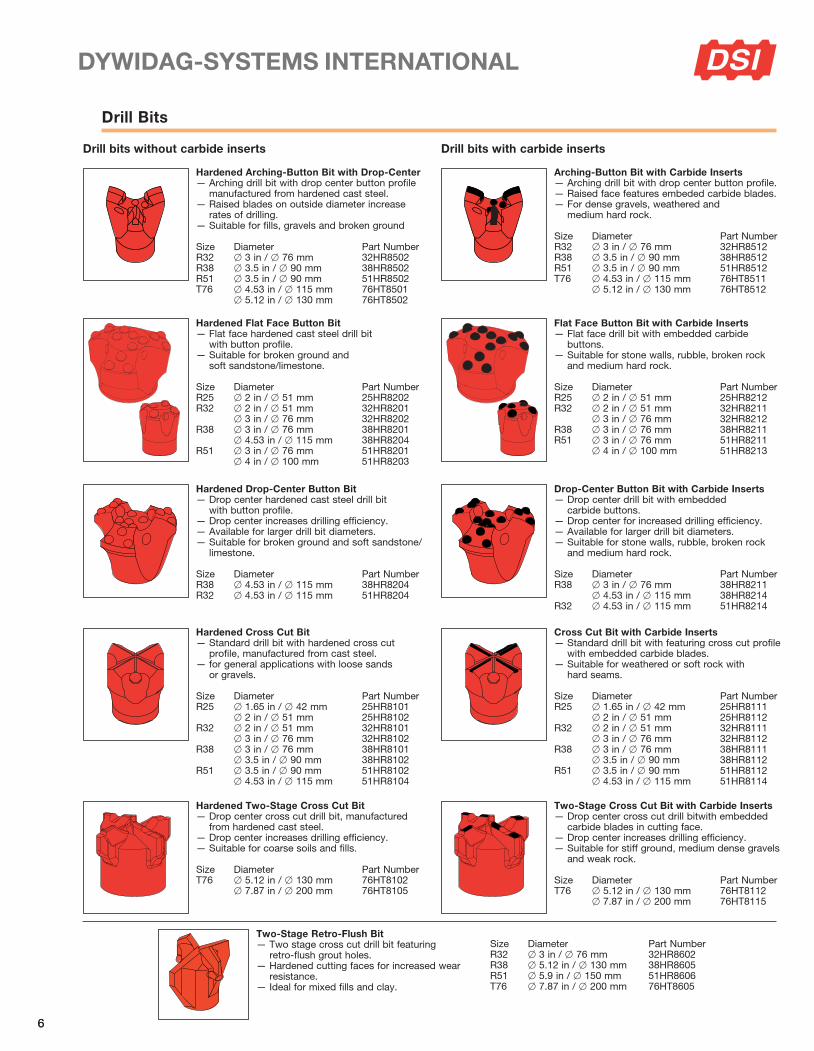
Drill Bits
Hardened Arching-Button Bit with Drop-Center— Arching drill bit with drop center button profile
manufactured from hardened cast steel.— Raised blades on outside diameter increase
rates of drilling.— Suitable for fills, gravels and broken ground
Size Diameter Part NumberR32 x 3 in / x 76 mm 32HR8502R38 x 3.5 in / x 90 mm 38HR8502R51 x 3.5 in / x 90 mm 51HR8502T76 x 4.53 in / x 115 mm 76HT8501 x 5.12 in / x 130 mm 76HT8502
Hardened Cross Cut Bit— Standard drill bit with hardened cross cut
profile, manufactured from cast steel.— for general applications with loose sands
or gravels.
Size Diameter Part NumberR25 x 1.65 in / x 42 mm 25HR8101 x 2 in / x 51 mm 25HR8102R32 x 2 in / x 51 mm 32HR8101 x 3 in / x 76 mm 32HR8102R38 x 3 in / x 76 mm 38HR8101 x 3.5 in / x 90 mm 38HR8102R51 x 3.5 in / x 90 mm 51HR8102 x 4.53 in / x 115 mm 51HR8104
Hardened Two-Stage Cross Cut Bit— Drop center cross cut drill bit, manufactured
from hardened cast steel.— Drop center increases drilling efficiency.— Suitable for coarse soils and fills.
Size Diameter Part NumberT76 x 5.12 in / x 130 mm 76HT8102 x 7.87 in / x 200 mm 76HT8105
Two-Stage Retro-Flush Bit — Two stage cross cut drill bit featuring
retro-flush grout holes.— Hardened cutting faces for increased wear
resistance.— Ideal for mixed fills and clay.
Size Diameter Part NumberR32 x 3 in / x 76 mm 32HR8602R38 x 5.12 in / x 130 mm 38HR8605R51 x 5.9 in / x 150 mm 51HR8606T76 x 7.87 in / x 200 mm 76HT8605
Hardened Drop-Center Button Bit — Drop center hardened cast steel drill bit
with button profile.— Drop center increases drilling efficiency.— Available for larger drill bit diameters.— Suitable for broken ground and soft sandstone/
limestone.
Size Diameter Part NumberR38 x 4.53 in / x 115 mm 38HR8204R32 x 4.53 in / x 115 mm 51HR8204
Hardened Flat Face Button Bit — Flat face hardened cast steel drill bit
with button profile.— Suitable for broken ground and
soft sandstone/limestone.
Size Diameter Part NumberR25 x 2 in / x 51 mm 25HR8202R32 x 2 in / x 51 mm 32HR8201 x 3 in / x 76 mm 32HR8202R38 x 3 in / x 76 mm 38HR8201 x 4.53 in / x 115 mm 38HR8204R51 x 3 in / x 76 mm 51HR8201 x 4 in / x 100 mm 51HR8203
Arching-Button Bit with Carbide Inserts— Arching drill bit with drop center button profile.— Raised face features embeded carbide blades.— For dense gravels, weathered and
medium hard rock.
Size Diameter Part NumberR32 x 3 in / x 76 mm 32HR8512R38 x 3.5 in / x 90 mm 38HR8512R51 x 3.5 in / x 90 mm 51HR8512T76 x 4.53 in / x 115 mm 76HT8511 x 5.12 in / x 130 mm 76HT8512
Cross Cut Bit with Carbide Inserts— Standard drill bit with featuring cross cut profile
with embedded carbide blades.— Suitable for weathered or soft rock with
hard seams.
Size Diameter Part NumberR25 x 1.65 in / x 42 mm 25HR8111 x 2 in / x 51 mm 25HR8112R32 x 2 in / x 51 mm 32HR8111 x 3 in / x 76 mm 32HR8112R38 x 3 in / x 76 mm 38HR8111 x 3.5 in / x 90 mm 38HR8112R51 x 3.5 in / x 90 mm 51HR8112 x 4.53 in / x 115 mm 51HR8114
Two-Stage Cross Cut Bit with Carbide Inserts— Drop center cross cut drill bitwith embedded
carbide blades in cutting face.— Drop center increases drilling efficiency.— Suitable for stiff ground, medium dense gravels
and weak rock.
Size Diameter Part NumberT76 x 5.12 in / x 130 mm 76HT8112 x 7.87 in / x 200 mm 76HT8115
Drop-Center Button Bit with Carbide Inserts— Drop center drill bit with embedded
carbide buttons.— Drop center for increased drilling efficiency.— Available for larger drill bit diameters.— Suitable for stone walls, rubble, broken rock
and medium hard rock.
Size Diameter Part NumberR38 x 3 in / x 76 mm 38HR8211 x 4.53 in / x 115 mm 38HR8214R32 x 4.53 in / x 115 mm 51HR8214
Flat Face Button Bit with Carbide Inserts— Flat face drill bit with embedded carbide
buttons.— Suitable for stone walls, rubble, broken rock
and medium hard rock.
Size Diameter Part NumberR25 x 2 in / x 51 mm 25HR8212R32 x 2 in / x 51 mm 32HR8211 x 3 in / x 76 mm 32HR8212R38 x 3 in / x 76 mm 38HR8211R51 x 3 in / x 76 mm 51HR8211 x 4 in / x 100 mm 51HR8213
Drill bits without carbide inserts Drill bits with carbide inserts

77
DYWI® Drill Hollow Bar System — Installation
DYWI® Drill Hollow Bar System is typically installed using rotary per cussive drilling. This tech ni que enables high rates of in stal lation, good directional stability and also helps to consolidate the grout within the borehole.
Rotation speeds should be sufficient to cut a true borehole (120-150 RPM for soil nails; 100-130 RPM for mini piles), as opposed to displacement of the soil with the drill bit through percussion and heavy feed pressures (driven installation). Drilled boreholes ensure enlarged grout bodies to gether with better permeation of the grout into the surrounding ground.
Feed pressures on the drill rods should be regulated in accordance with the cutting performance of the drill bit.
Simultaneous Drilling and GroutingSuitable for granular soils and fills. This installation method utilises a Grout Swivel (see page 12), grout pump and drilling head (drifter, as shown, top). The technique combines drilling and grouting as a single operation, ensuring that grout is placed over the full length of the borehole. For ground conditions where borehole colla pse is anticipated or where subsequent grout injection down the center of the bar is problematical, simultaneous drilling and grouting is the preferred solu tion.
Grouting pressures should be regulated to maintain circulation at all times (typically up to 100 psi), with a small amount of grout return visible at the mouth of the bore hole. Pressures in excess of 100 psi are generally only required for special ap plications (i.e. anchors in cohesive soils or mining applications).
The choice of grout pump varies between applications, but basic requirements are as follows:
a) thorough mixing of the grout — to avoid blockages at the drill bit
b) delivery of a continuous volume — to ensure consistent grouting
c) maintenance of sufficient pressure
Installation of DYWI® Drill Rock BoltsRotary percussive drilling head (drifter) with rotary injection adaptor for grout injection
Lightweight rotary percussive drilling rig (for restricted access)
88
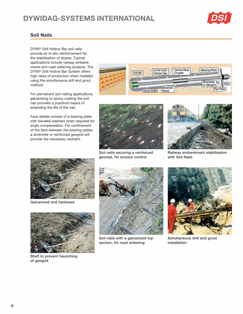
Soil Nails
DYWI® Drill Hollow Bar soil nails provide an in-situ re inforcement for the stabilisation of slopes. Typical applications include railway embank-ments and road widening projects. The DYWI® Drill Hollow Bar System offers high ra tes of production when installed using the simul taneous drill and grout method.
For permanent soil nailing applications, galvanizing or epoxy coating the soil nail provides a practical means of extending the life of the nail.
Face details consist of a bearing plate with beveled washers when required for angle compensation. For confinement of the face between the bearing plates, a shotcrete or reinforced geogrid will provide the necessary restraint.
Soil nails securing a reinforced geomat, for erosion control
Soil nails with a galvanized top section, for road widening
Galvanized end hardware
Shelf to prevent haunching of geogrid
Simultaneous drill and grout installation
Railway embankment stabilisation with Soil Nails

99
Micro Piles
DYWI® Drill Injection Piles consist of a micro pile (or mini pile) bar that can be both drilled and injected with grout during installation. The fully threaded rod sections can be cut and coupled at any point, enabling quick and easy installation in areas of restricted access or limited headroom.
Installation through an existing slab
Underpinning of augered columns
Fully grouted micro pile
Refurbishment of existing column bases
Upgrading of existing foundations
Installation of DYWI® Drill Injection Piles
Installation of DYWI® Drill Injection Piles causes minimal disturbance to surrounding struc tures.The system also enables additional rod sections to be added in-situ, for pile extension in poor ground where the depth of the bearing strata is unknown. Simul taneous drilling and grouting ensures that the grout is continuously placed over the full depth of the micro pile, enabling grout to permeate the surrounding ground and increase skin friction. Rotary percussive installation ensures high rates of production and provides good directional stabi lity if obstructions are encountered.
Applications for DYWI® Drill Injection Piles inclu de but are not limited to: column bases, foundation upgrades, mast stabilisation, refurbishment of old structures, and gantry bases for overhead power lines on electric rail projects.
1010
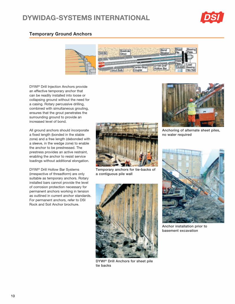
DYWI® Drill Injection Anchors provide an effective temporary anchor that can be readily installed into loose or collapsing ground without the need for a casing. Rotary percussive drilling, combined with simul ta neous grouting, ensures that the grout penetrates the surrounding ground to pro vide an increased level of bond.
All ground anchors should incorporate a fixed length (bonded in the stable zone) and a free length (debonded with a sleeve, in the wedge zone) to enable the anchor to be prestressed. The prestress provides an active restraint, enabling the anchor to resist service loadings without additional elongation.
DYWI® Drill Hollow Bar Systems (irrespective of threadform) are only suitable as temporary anchors. Rotary installed bars cannot provide the level of corrosion protection necessary for permanent anchors working in tension as outlined in current anchor standards. For permanent an chors, refer to DSI Rock and Soil Anchor brochure.
Temporary Ground Anchors
temporary anchors for tie-backs of a contiguous pile wall
anchoring of alternate sheet piles, no waler required
DYWI® Drill anchors for sheet pile tie backs
anchor installation prior to basement excavation

1111
Rock Bolts & Spiles
Rock bolts are passive ties; typically classified as lightly loaded, short installations. DYWI® Drill Hollow Bar System provides a practical rock bolt that is quick and easy to install through fractured or broken ground. The system is available with a range of harder drill bits (Tungsten Carbide: button or chisel) for efficient drilling in stronger material.
Spiles provide a protective canopy, to enable the heading of a tunnel to be advanced without the risk of falling debris. Often used with NATM — New Austrian Tunneling Method — construction.
DYWI® Drill Hollow Bar System Spiles enable drilled installation, reducing localised disruption and providing a conduit for grouting. Subsequent grouting assists in the consolidation of the surrounding ground.
DYWI® Drill Hollow Bar Rock Bolts
tunnel portal stabilization
Spiles for support of tunnel crown
Air or water flush percussive drilling is normally employed for installation, followed by subsequent grout injection through the bore of the bar. Injected grout provides the bond for the DYWI® Drill Hollow Bar and also helps to consolidate fractured ground.
For mining applications, the DYWI® Drill Hollow Bar System is used as self- drilling rock bolt in areas of high stress at pillars, crossheads or abutments. Other applications in clude the use of the self-drilling bar as an in jection conduit for resin, grout or waterproofing agents.
DYWI® Drill Hollow Bar Spiles

1212
DYWI® Drill Hollow Bar System — Installation Accessories
Grout SwivelsGrout Swivels are used for simul-taneous drill and grout installation, to inject grout into the bore of a rotating DYWI® Drill Hollow Bar. The unit comprises of a heat treated shaft (to withstand the impact energy from the hammer drive) and a housing into which the grout is pumped. Inlet ports within the shaft, enable grout to be pumped into the bore of the bar.
A bracket is required (attached to the drifter) to prevent the housing from rotating with the shaft, as well as positioning it at the correct location to enable unrestricted operation of the hammer.
Drill ToolingA range of drill accessories are available, to enable connection between the output drive of the drilling head and the different DYWI® Drill Bar diameters.
Grout Swivel (rig installation)
Simultaneous drill and grout installation
Grout Swivel fitted below drill head
Grout Injection coupler(for subsequent grouting)
Balance Rod Reducing coupler
Reducing coupler(with centre bridge)
Grout Swivel (hand held installation)
air Flush Shank (hand held installation)

1313
Stressing and Testing
Soil Nail TestingSoil nail testing is used to establish the bond stress within the stable zone of a slope. Load generated in the wedge (re tained) zone is usually discounted as it does not contribute to the underlying stability of the nailed slope. As DYWI® Drill Hollow Bar System soil nails are typically fully grouted (the refore fully bonded), it is necessary to either wash back the grout in the wedge zone with a lance, or establish the influen ce of the wedge zone bond on the final load, so that an accurate assessment of the load in the stable zone can be made.
Nail load is measured through a pressure gauge incorporated in the jack circuit, with extension recorded by a dial gauge mounted independently.
Bearing surfaces, for the jack platform, should be perpendicular to the angle of installation and have sufficient bearing area to resist settlement as the nail is tested. An alignment load in the jack will ensure correct orientation of the soil nail prior to measuring its elongation.
Micro Pile TestingA range of tests are used to establish the settlement characteristics of micro piles. Compression testing generally falls into two categories, static or dynamic.
Static testing employs anchor piles or temporary bearing yoke to provide the reaction against which the micropile is loaded; dis placement can then measured against load.
Tensile pile testing in volves loading the micropile with a jack, from a bearing plat form that spans outside the cone of influence. Load is measured through the jack, with extension recorded from an independent reference point.
Temporary Ground Anchor TestingProof testing is employed to demonstrate the anchor performance, prior to exca vation at the front of the face. For temporary anchors, the proof load is generally 133 % to 150 % of the working load. Following proof loading, anchors are locked-off at working load to provide an active restraint to the structure.
testing of DYWIDaG Soil Nail
tensile test on a temporary anchor pile
DYWI® Drill anchor testing
testing of DYWI® Drill Hollow Bars for slope stabilization

1414
Shoring for reconstruction of Little Mountain Reservoir using DYWI® Drill Hollow BarsLittle Mountain Reservoir, GVRD (Greater Vancouver Regional District), Vancouver, BC, Canada
References
Owner GVRD (Greater Vancouver Regional District), Vancouver, BC, Canada +++ Engineer Sandwell Engineering, Vancouver, BC, Canada +++ Geotechnical Engineer Golder Associates Ltd., Vancouver, BC, Canada +++ General Contractor Graham Industrial Services Ltd., Vancouver, BC, Canada +++ Shoring Contractor Southwest Contracting Ltd., Vancouver, BC, CanadaDSI Services Supply of DYWI® Drill Hollow Bars with 3 and 4 m length: 4,500 m R32N, 4,400 m R32S and 1,500 m R38; technical assistance
i
Use of DYWI® Drill Hollow Bars to upgrade Centennial Bridge foundationFairchild Creek Viaduct, Brantford, Ontario, Canada
Client Canadian National Railway, Gormley, ON, Canada +++ General Contractor Geo-Foundations Contractors Inc., Bolton, ON, Canada +++ Consulting Alston Associates, Markham, ON, CanadaDSI Services Supply of metallized DYWI® Drill Hollow Bars type R32N and components for bridge foundation remediation scheme
i
Shoring works with DYWI® Drill Self-Drilling Hollow Bar Soil Nails
Drilling works at pier footings
Slope stabilization with 15 m long DYWI® Drill Self-Drilling Hollow Bar Soil Nails

15
Owner Brantford General Hospital, Brantford, Ontario, Canada +++ General Contractor Bondfield Construction, Concord, Ontario, Canada +++ Consulting Engineers Carruthers & Wallace Limited, Toronto, Ontario, Canada +++ Contractor for foundations HC Matcon Inc., Ayr, Ontario, Canada +++ Engineer for foundations Isherwood Associates Ltd., Mississauga, Ontario, CanadaServices Supply of 40,000 ft DYWI® Drill Hollow Bar Soil Nails for the shotcrete wall
i
Shotcrete wall with DYWI® Drill Hollow Bars
15
Brantford General Hospital, Brantford, Ontario, Canada
References
“Electra”1,020m DYWI® Drill Hollow Bar Anchors secure the old SDGE Station in San Diego
Owner Bosa Development California II, Inc, British Columbia, Canada +++ Contractor Bosa Development California II, Inc, British Columbia, Canada +++ Subcontractor Condon-Johnson & Assoc. Inc., San Diego, CA, USADSI Services Supply of approximately 10,000 ft. T76S DYWI® Drill Bars with accessories such as couplers, nuts and bits
i

0417
7-1U
S/0
7.11
web
cb
Det
ails
, Dim
ensi
ons
and
syst
em d
esig
ns a
re s
ubje
ct t
o ch
ange
with
out
notic
e.A r g e n t i n A
A u s t r A l i A
A u s t r i A
b e l g i u m
b o s n i A A n d h e r z e g o v i n A
b r A z i l
C A n A d A
C h i l e
C h i n A
C o l o m b i A
C o s t A r i C A
C r o A t i A
C z e C h r e p u b l i C
d e n m A r k
e g y p t
e s t o n i A
F i n l A n d
F r A n C e
g e r m A n y
g r e e C e
g u A t e m A l A
h o n d u r A s
h o n g k o n g
i n d o n e s i A
i t A l y
J A p A n
k o r e A
l e b A n o n
l u x e m b o u r g
m A l A y s i A
m e x i C o
n e t h e r l A n d s
n o r w A y
o m A n
p A n A m A
p A r A g u A y
p e r u
p o l A n d
p o r t u g A l
Q A t A r
r u s s i A
s A u d i A r A b i A
s i n g A p o r e
s o u t h A F r i C A
s p A i n
s w e d e n
s w i t z e r l A n d
t A i w A n
t h A i l A n d
t u r k e y
u n i t e d A r A b e m i r A t e s
u n i t e d k i n g d o m
u r u g u A y
u s A
v e n e z u e l A
www.dsiamerica.comwww.dsicanada.ca
DYWIDAG-SystemsInternational USA Inc.
320 Marmon DriveBolingbrook, IL 60440Phone (630) 739-1100Fax (630) 739-5517E-Mail [email protected]
1591 E. Atlantic Blvd #200Pompano Beach, FL 33060Phone (954) 532-1326Fax (954) 532-1330E-Mail [email protected]
5139 South Royal Atlanta DriveTucker, GA 30084Phone (770) 491-3790Fax (770) 938-1219E-Mail [email protected]
2400 Hwy 287 N.Suite 106Mansfield, TX 76063Phone (817) 473-6161Fax (817) 473-1453E-Mail [email protected]
2154 South StreetLong Beach, CA 90805Phone (562) 531-6161Fax (562) 531-3266E-Mail [email protected]
1314 Central Ave SouthSuite 100Kent, WA 98032Phone (253) 859-9995Fax (253) 859-9119E-Mail [email protected]
1263 Newark RoadToughkenamon, PA 19374Phone (610) 268-2221Fax (610) 268-3053E-Mail [email protected]
DYWIDAG-SystemsInternational Canada Ltd.
Eastern Division37 Cardico DriveGormley, ON L0H 1G0Phone (905) 888-8988Fax (905) 888-8987E-Mail [email protected]
Quebec OfficeC.P. 412St. Bruno, Quebec, QC, J3V 5G8Phone (450) 653-0935Fax (450) 653-0977E-Mail [email protected]
Western Division19433 96th AvenueSuite 103Surrey, BC V4N 4C4Phone (604) 888-8818Fax (604) 888-5008E-Mail [email protected]
Calgary Office2816 - 21st Street NE., #204Calgary, Alberta T2E 6Z2Phone (403) 291-4414Fax (403) 250-5221E-Mail [email protected]
Please note: This brochure serves basic information purposes only. Technical data and information provided herein shall be considered non-binding and may be subject to change without notice. We do not assume any liability for losses or damages attributed to the use of this technical data and any improper use of our products. Should you require further information on particular products, please do not hesitate to contact us.